Horizon Hobby XP6102 JR XP6102 FM 6 channel radio system User Manual XP6102 Section 1
Horizon Hobby, LLC JR XP6102 FM 6 channel radio system XP6102 Section 1
XP6102 User Manual
INSTRUCTION MANUAL FOR
AIRPLANE AND HELICOPTER
FPO FPO
FPO
XP6102
6-CHANNEL COMPUTER RADIO SYSTEM
CAN YOU FEEL IT?

xSECTION 1
TABLE OF CONTENTS
2XP6102 - Introduction

TABLE OF CONTENTS x
3XP6102 - Introduction

xTABLE OF CONTENTS
4XP6102 - Introduction

SECTION 1 x
5XP6102 - Introduction

1USING THIS MANUAL
In the beginning of this manual you will
find the specifications for the radio and its
various accessories. In addition,
guidelines for the installation has been
included. Instructions for setting all the
functions and programs of the X-6102 are
also included. These features are discussed
in the same order that they will appear in
your radio, as you will see on the
accompanying pages. An explanation of
the use and purpose of each feature is
provided, followed by a labeled
illustration of its respective LCD display.
In addition, a step-by-step example
clarifies the setup procedure of the
feature.
A blank data sheet has been included at
the end of each section. Once all data has
been input for a particular model, it is
highly recommended that you record it on
a copy of the sheet provided. If you
should experience memory loss or battery
failure or want to make changes to the
current settings, this step will save you a
great deal of time.
CHAPTER 1: USING THIS MANUAL • INTRODUCTION
6XP6102 - Introduction
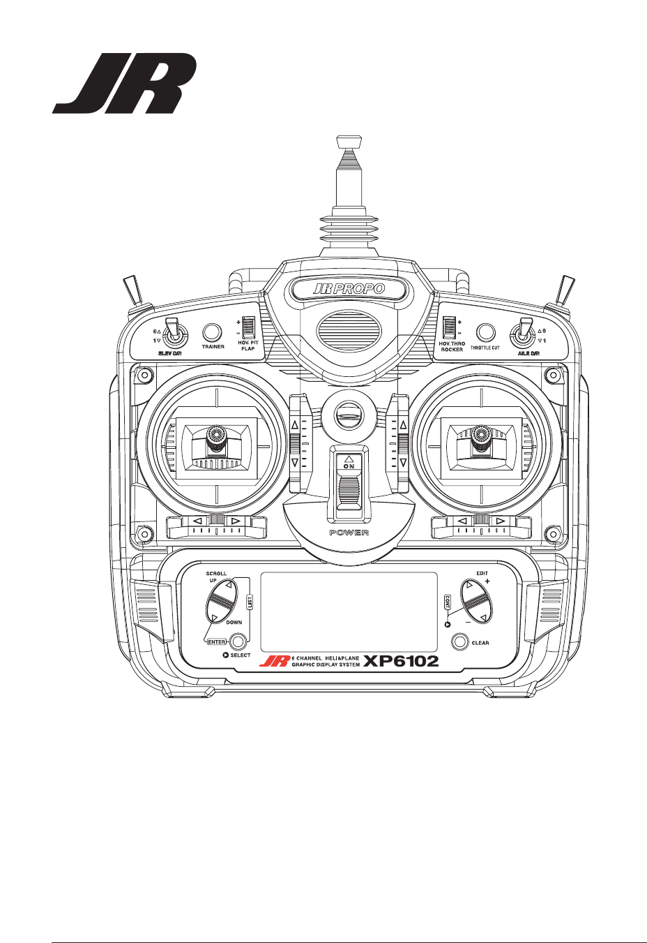
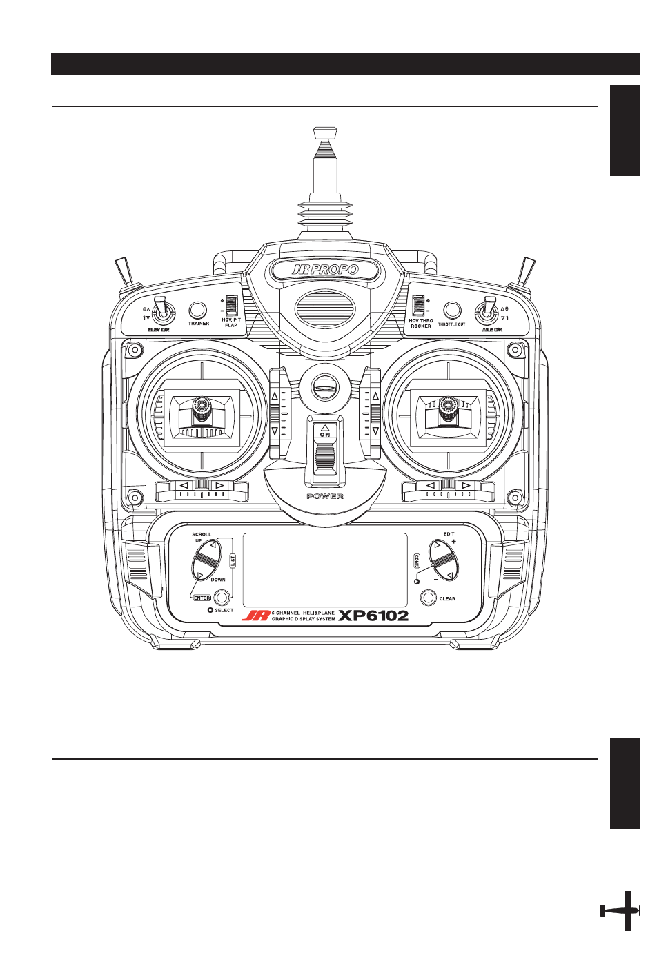
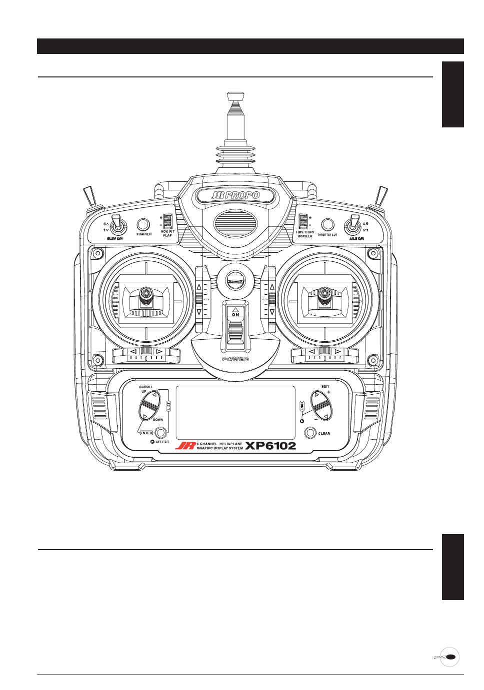
2.1 X-6102 TRANSMITTER
The computer designed, ergonomically
styled transmitter case ensures a
comfortable fit in your hands. The ultra-
precision control sticks offer adjustable
spring tensions and length. The throttle
stick offers a ratchet in Airplane
configuration. 10-model memory storage
allows programming of all parameters of
ten separate helicopters or airplanes; you
can program more than one setup for a
single aircraft, allowing you to instantly
change the flight characteristics.
A five-year lithium backup battery
prevents loss of memory in the event
that the battery discharges completely
or is removed.
CHAPTER 2: FEATURES
2.2 R770 RECEIVER
R770 (PCM Systems)
The R770 is a high-performance PCM or
single-conversion receiver with 10KHz
super narrow band ABC&W circuitry.
A narrow band ceramic filter for high-
signal selectivity assists in rejecting cross
modulations from other common radio
frequencies-e.g. R/C transmitters, local
paging systems. This receiver features
Direct Servo Control (DSC) for control of
surfaces without radio frequency output.
The receiver has low current
consumption.
The R770's Slimline design allows it to fit
into most model applications.
S537 BALL BEARING SERVO 2.3
537 Servo
• Wide spaced ball bearing for precise
movement of your aircraft control
outputs
• A zero deadband amplifier insures
accurate neutral centering
• Low current drain
• Indirect drive feedback potentiometer
gives additional protection from
vibration7
• 3-pole ferrite cored motor
7XP6102 - Introduction
CHAPTER 3: COMPONENT SPECIFICATIONS
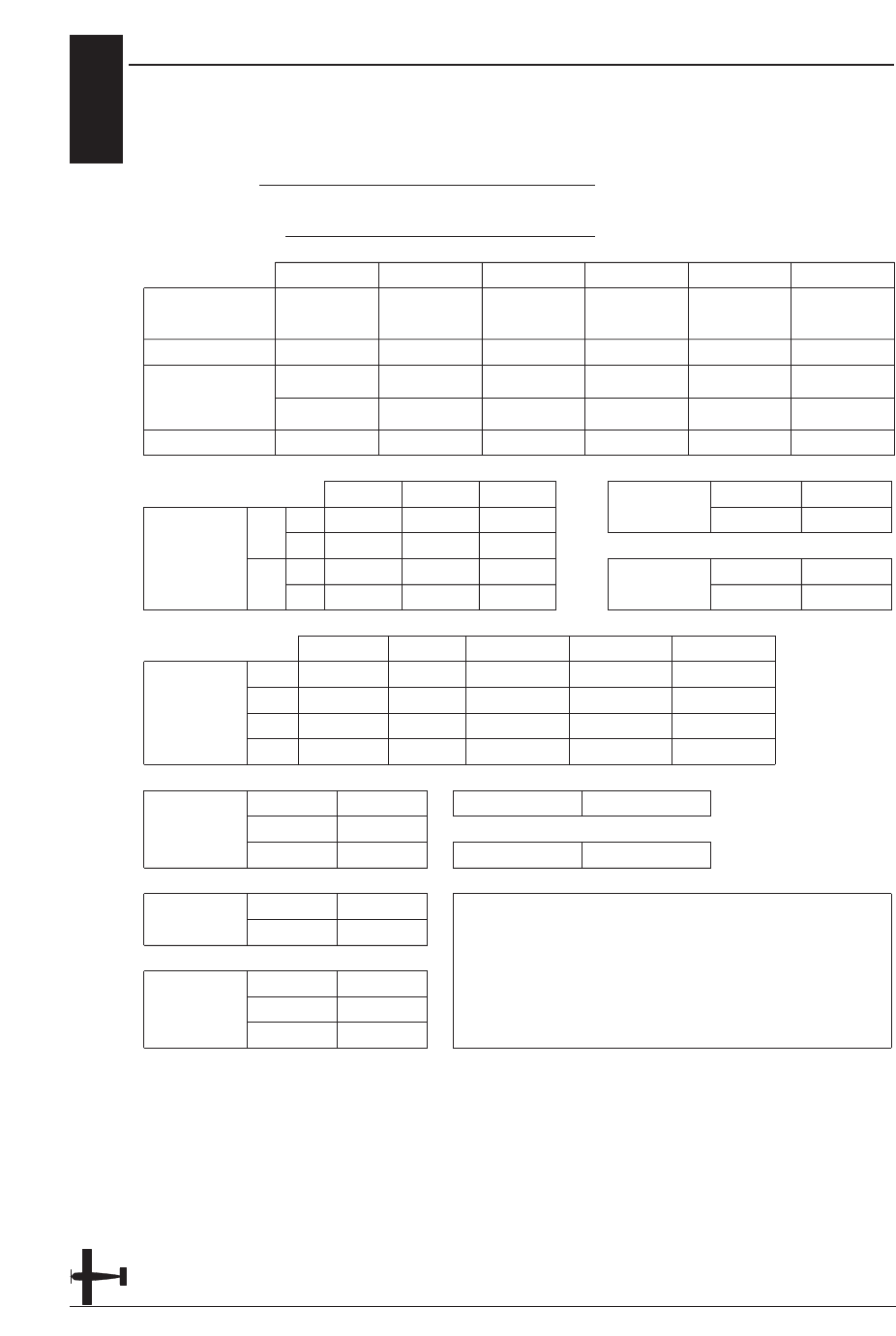
SYSTEM SPECIFICATIONS 3.1
TYPE AIRPLANE HELICOPTER
SYSTEM NAME X-6102A X-6102H
TRANSMITTER BODY NET-K236US Net-K236US
RECEIVER R700 (FM) or R770 (PCM) R700 (FM) or R770 (PCM)
CHARGER NEC-222 NEC-222
AIRBORNE BATTERY 1100mah 1100mah
SERVOS NES-537X4 NES-537X5
ACCESSORIES Standard Switch Standard Switch
12" Aileron Extension 12" Aileron Extension
Charge Jack Charge Jack
Servo Accys Servo Accys
Hex Wrench Hex Wrench
Instruction Manual Instruction Manual
TRANSMITTER SPECIFICATIONS 3.2
TYPE AIRPLANE HELICOPTER
MODEL NUMBER NET-K236US NET-K236US
ENCODER 6–channel computer system 6–channel computer system
RF MODULE 72MHz 72MHz
MODULATION PCM (s) or PPM PCM (s) or PPM
OUTPUT POWER Approximately 750mw Approximately 750mw
CURRENT DRAIN 200mA (70mA with DSC) 200mA (70mA with DSC)
POWER SOURCE 1.2Vx Ni-Cd (9.6V) 600mAh 1.2Vx Ni-Cd (9.6V) 600mAh
OUTPUT PULSE 1000–2000 (1500 Neutral) 1000–2000 (1500 Neutral)
3.3 SERVO SPECIFICATIONS
TYPE 537
TORQUE (ounce inch) 43 oz/in
SPEED (sec/60°) .25 60°
WEIGHT 1.58
SIZE (in) (L x W x H) 1.52 x 0.73 x 1.32
BB Single
MOTOR 3-Pole Ferrite
8XP6102 - Introduction
3.4 RECEIVER SPECIFICATIONS
TYPE FM PCM
MODEL NUMBER R700 R770
TYPE 7 Channel / FM-ABC&W / Micro 7 Channel / FM-ABC&W / Micro
FREQUENCY 72MHz 72MHz
SENSITIVITY (Microseconds) 5 uS minimum 5 uS minimum
SELECTIVELY 8KHz / 5 dB 8KHz / 5 dB
WEIGHT (oz) 1.5 1.5
RECEIVER ANTENNA 39“ for all aircraft frequencies 39“ for all aircraft frequencies
3.5 CHARGER SPECIFICATIONS
TYPE AIRCRAFT HELICOPTER
MODEL NUMBER NEC-222 NEC-222
INPUT VOLTAGE AC 100–120V AC 100–120V
OUTPUT CURRENT 50mAh TX/120mAh RX 50mAh TX/120mAh RX
CHARGING TIME 15 Hours 15 Hours
3.6 AIRBORNE BATTERY PACK
TYPE AIRCRAFT HELICOPTER
MODEL NUMBER B1100 B1100
VOLTAGE 4.8 V 4.8 V
SIZE (in) (W x L x H) 2.24 x 0.63 x 1.70 2.24 x 0.63 x 1.70
WEIGHT (oz) 4.9 4.9
CHAPTER 4: BATTERY CHARGING
TRANSMITTER/RECEIVER 4.1
Note: It is imperative that you fully
charge both the transmitter and the
receiver battery packs prior to each
trip to the field. To do so, leave the
charger and batteries hooked up
overnight (16 hours). The first charge
should be approximately 20–24 hours
in order to fully charge both battery
packs to peak capacity.
The charger supplied with this system is
designed to recharge your batteries at a
rate of 50mAh for the transmitter and
120mAh for the receiver battery pack.
Transmitter Only
The center pin on all JR Remote Control
Systems is negative. Therefore, the center
pin on all JR chargers is negative, not
positive. This is different from many other
manufacturers' chargers and radio
systems. Beware of improper connections
based on "color-coded" wire leads, as they
do not apply in this instance. You must
make sure that the center pin of your JR
transmitter is always connected to the
negative voltage for correct polarity
hookup.
Important: Please note that the charging
polarity of the transmitter and
receiver are different.
9XP6102 - Introduction
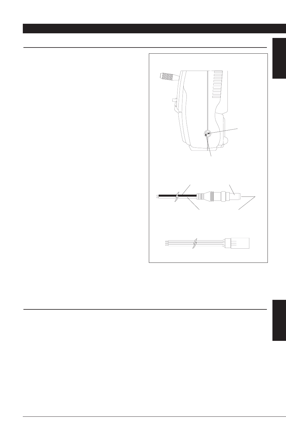
CENTER
PIN IS
NEGATIVE
OUTSIDE IS POSITIVE
RIGHT SIDE OF TRANSMITTER
RED–POSITIVE / BROWN–NEGATIVE / ORANGE–SIGNAL
RED TO NEGATIVE
BLACK TO POSITIVE
CHARGER PIGTAIL FOR TRANSMITTER
CHARGER PIGTAIL FOR RECEIVER
CHARGER 4.2
The pilot lamps should always be on
during the charging operation. If not,
check to make sure that both the
transmitter and receiver are switched off.
Do not use the charger for equipment
other than JR. The charging plug polarity
may not be the same. Equipment damage
can result.
Do not use other manufacturers' after-
market accessories that plug into the
transmitter's charging jack. If you do, any
damage that results will not be covered by
warranty. If you are unsure of
compatibility issues with your radio, seek
expert advice to avoid possible damage.
During the charging operation, the
charger's temperature is slightly elevated.
This is normal.

4.3 ADVANCED DIGITAL TRIMS
The XP6102's digital trims also feature the
Direct Access display function. While at
the Normal display screen, if a trim lever
is moved, the screen will automatically
change to display the numeric value, as
well as the graphic position for the trim
being adjusted. The XP6102's Aileron,
Elevator, Throttle and Rudder trim levers
feature an audible center trim beep. This is
helpful in determining the trim levers
center position during flight.
Please also note that unlike conventional
mechanical trim levers, when the X-6102
transmitter is in the off position, no
changes can be made to the trim values
during transportation.
10 XP6102 - Introduction
CHAPTER 1: SOFTWARE FUNCTIONS - AIRPLANE
CONTROL IDENTIFICATION AND LOCATION 1.1
9XP6102 - Airplane Manual
FPO FPO
FPO
CHANNEL ASSIGNMENT/THROTTLE ALT 1.2
Channel TX Function Airplane Function
1THRO Throttle Channel
2AILE Aileron Channel
3ELEV Elevator Channel
4RUDD Rudder Channel
5GEAR Gear Channel
6AUX 1 Auxiliary 1
Channel (Flap)
Throttle ALT
The Throttle ALT function makes the
throttle stick trim active only when the
throttle stick is at less than half throttle.
This gives easy, accurate idle adjustments
without affecting the high throttle
position.
S
E
C
T
I
O
N
II
•
A
I
R
C
R
A
F
T

xSECTION 1
10 XP6102 - Airplane Manual
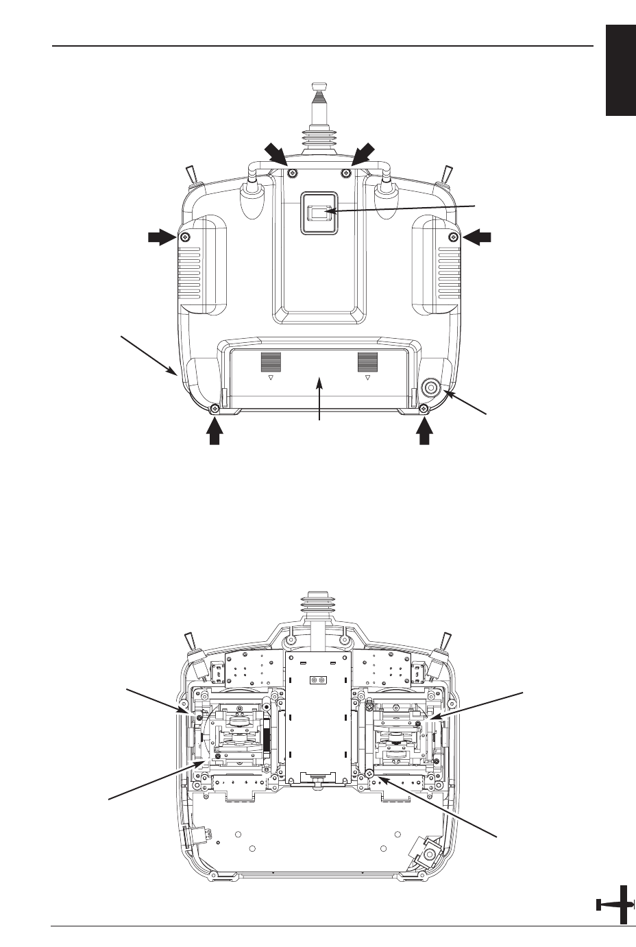
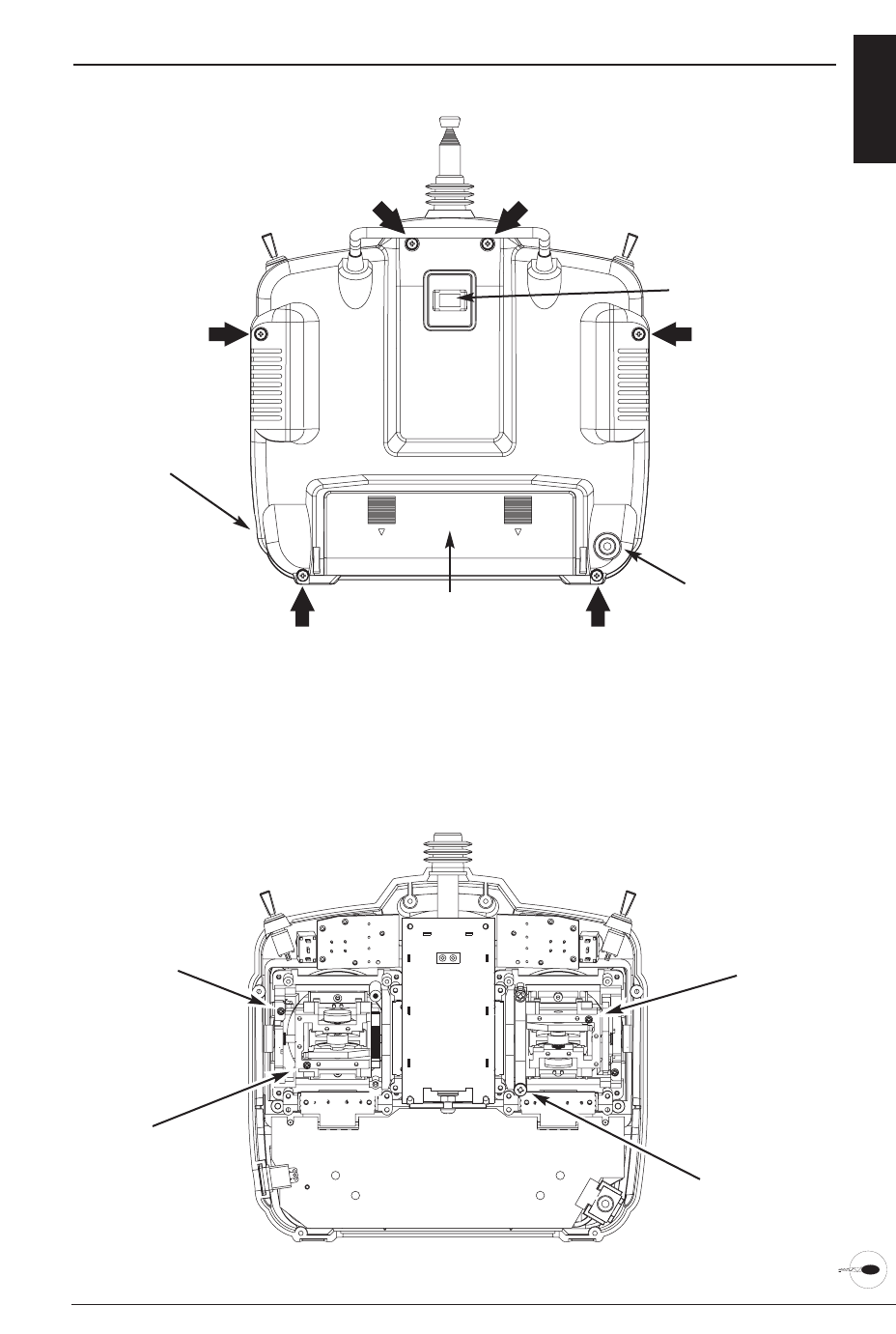
TRANSMITTER REAR x
11XP6102 - Airplane Manual
TRANSMITTER CRYSTAL
DSC/TRAINER JACK
CHARGING JACK
FOR NI-CD BATTERY
ONLY (8N-600)
BATTERY COVER
CAUTION: THE BATTERY CONNECTOR
IS KEYED SO THAT IT CAN ONLY BE PLUGGED
IN ONE DIRECTION. DO NOT FORCE.
Transmitter Crystal Replacement Notice
The Federal Communications Commission (FFC) requires that
changes in transmitter frequency must be performed only by
an authorized service technician (Horizon Service Center). Any
transmitter frequency change made by non-certified
technician may result in a violation of the FCC rules.
RUDDER TENSION
SCREW
THROTTLE TENSION
SCREW
ELEVATOR TENSION
SCREW
AILERON TENSION
SCREW
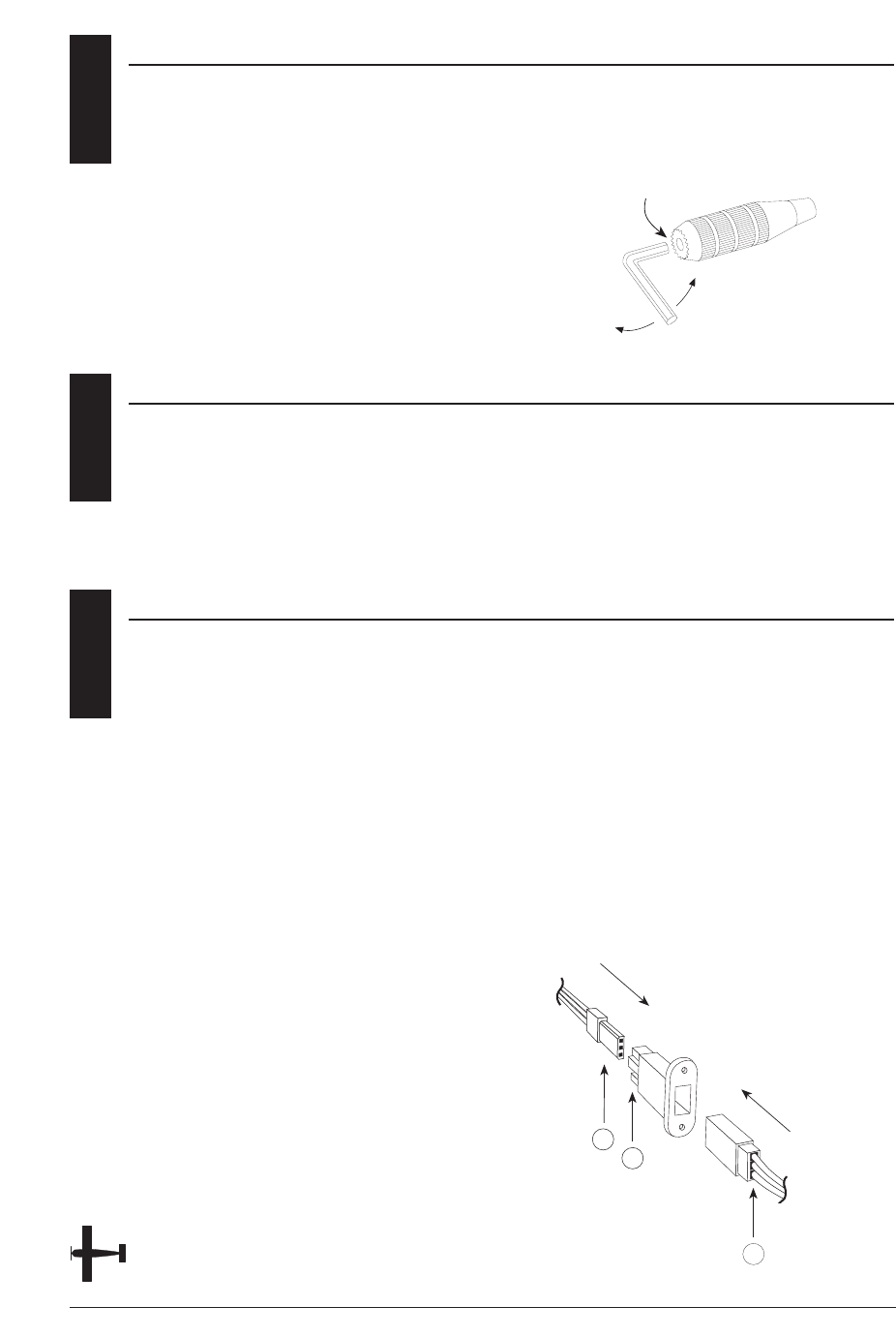
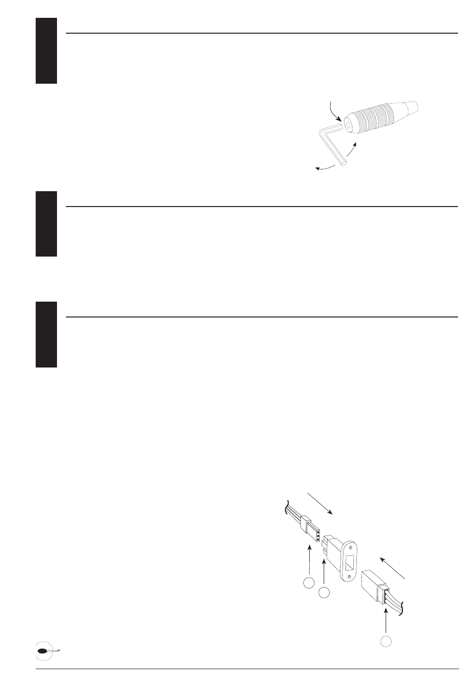
1.4 CONTROL STICK LENGTH ADJUSTMENT
To adjust the stick length, use the
2mm Allen wrench (supplied with your
XP6102 transmitter) to unlock the set
screw. Turn the wrench counterclockwise
to loosen the screw. Then, turn the
stick clockwise to shorten or
counterclockwise to lengthen. After the
control stick length has been adjusted
to suit your flying style, tighten the
2mm set screw. If you desire longer sticks,
JR offers a stick (JRPA047) that is
12 XP6102 - Airplane Manual
1.5 CONTROL STICK TENSION ADJUSTMENT
Remove the Ni-Cd battery and six
transmitter back screws as shown on the
previous page. Remove the transmitter
back, being careful not to cause damage
to any components.
Adjust each screw for desired tension
(counter-clockwise to loosen stick feel;
clockwise to tighten stick feel). When
adjusting the throttle ratchet tension,
make sure that the adjusting screw
does not touch the PC board after
adjustment is complete.
LOOSEN
TIGHTEN
SET SCREW
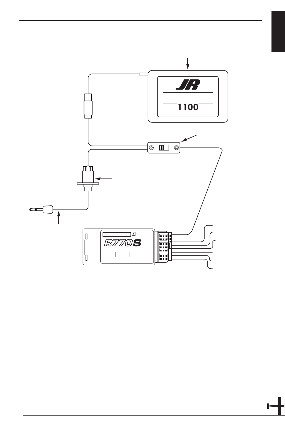
1.6 DIRECT SERVO CONTROL (DSC)
For proper DSC hook-up and operation:
1. Leave the transmitter power switch in
the Off position. The transmitter will not
transmit any radio frequency (RF) in this
position.
2. Plug the (supplied) DSC cord into the
DSC port in the rear of the transmitter.
3. The encoder section of the transmitter
will now be operational and the LCD
display will be lit.
4. Plug the other end of the DSC Cord
into the receiver charge receptacle. Turn
the switch harness to the On position.
Note: When you install the charging
jack, be sure to hook the charging
jack receptacle securely into the
switch harness charge cord.
Why you should use the DSC function:
1. The DSC enables you to check the
control surfaces of your aircraft without
drawing the fully operational 200mAh
from your transmitter battery pack.
Instead, you will only draw
approximately 70mAh when using the
DSC function.
2. The DSC function allows you to make
final adjustments to your airplane
without transmitting any radio signals.
Therefore, if another pilot is flying on
your frequency, you can still adjust your
aircraft and not interfere with the other
pilot’s aircraft.
Note: Under no circumstances should
you attempt to fly your aircraft with
the DSC cord plugged in! This
function is for bench-checking your
airplane only.
approximately one inch longer than
standard. This stick, crafted from bar
stock aluminum, is available at your
local JR dealer.
A
B
C
A—Charge Cord/DSC Receptacle
B—Switch Harness Lead
C—Charger/DSC Cord

NECK STRAP ATTACHMENT 1.7
An eyelet is provided on the face of the
XP6102 transmitter that allows you to
connect a Neck Strap (JRPA023). This
hook has been positioned so that your
transmitter has the best possible balance
when you use the neck strap.
13XP6102 - Airplane Manual
BASE LOADED ANTENNA 1.8
An optional base-loaded antenna is
available for use with the XP6102
transmitter. It is considerably shorter than
the standard antenna. However, the base
loaded antenna cannot be collapsed for
storage in side of the transmitter. You must
also use an adapter (JRPA156) to attach
the antenna to your XP6102. The Base
Loaded Antenna (JRPA155) is made of a
flexible coil and is covered with a soft
plastic material. Your range will not be
affected when using the base loaded
antenna.
FREQUENCY NOTES/AIRCRAFT ONLY FREQUENCIES 1.9
The XP6102 transmitter employs a plug-in
crystal for the transmitter that is glued in
place at the time of shipment. Per FCC
regulation, the transmitter crystal should
only be changed by a certified technician.
Changing of the transmitter crystal by a
non-authorized technician could result in
a violation of FCC rules.
The XP6102 can transmit in either Pulse
Code Modulation (PCM) or Pulse Position
Modulation (PPM, commonly referred to
as FM).
Be certain to observe the following
guidelines:
1. Do not operate your transmitter when
another transmitter is using the same
frequency, regardless of whether the
second transmitter is PCM, PPM (FM) or
AM. You can never operate two
transmitters on the same frequency
simultaneously without causing
interference.
2. For operation of your X-378 with
additional receivers, you should refer to
the receiver compatibility chart. The chart
is located in the Modulation Selection
Section of this manual.
Aircraft-Only Frequencies
JR Transmitters and receivers are available
in 72MHz frequencies in the United
States for use with model aircraft.
Employing 72MHz frequencies does not
require a special operator’s license from
the Federal Communications Commission
(FCC).
* A chart for all available frequencies is
located on page xxx of this manual.
2.1 INSTALLATION REQUIREMENTS
It is extremely important that your radio
system be correctly installed in your
model. Here are a few suggestions
installing your JR equipment:
1. Wrap the receiver in protective foam
rubber that is no less than 3/8 inch thick.
Secure the foam to the receiver with #64
rubber bands. This protects the receiver
in the event of a crash or a very hard
landing.
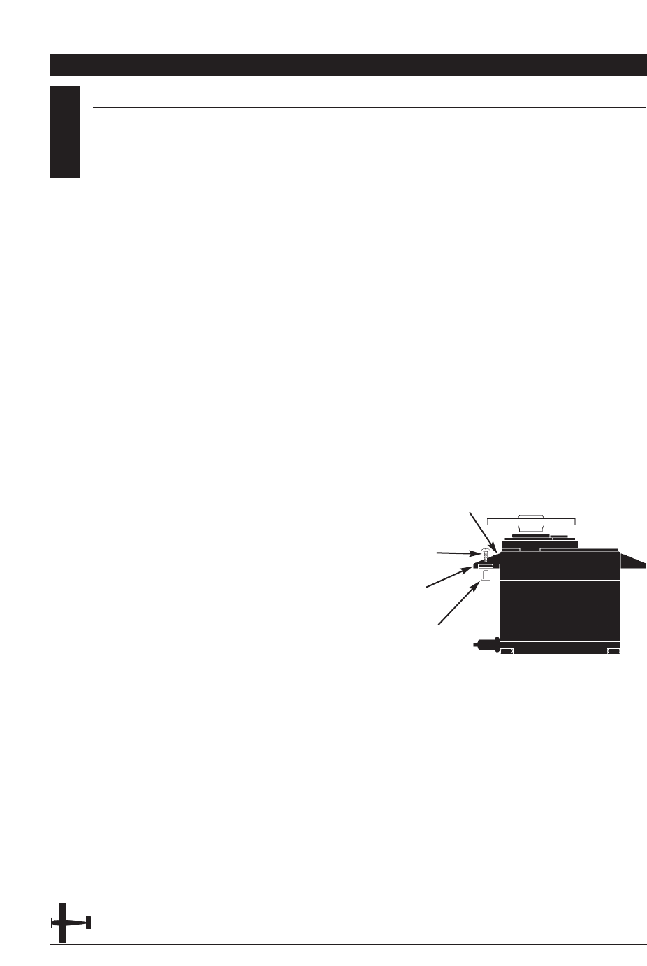
2. The servos should be mounted using
rubber grommets and brass eyelets to
isolate them from vibration. Do not over-
tighten the mounting screws; this will
negate the vibration absorption effect of
the rubber grommets. The following
diagram will assist you in properly
mounting your servo.
The brass eyelets are pushed from the
bottom up in the rubber grommets.
When the servo screw is tightened
securely, it provides the proper security
as well as the proper vibration isolation
for your servo.
3. The servos must be able to move freely
over their entire range of travel. Make
sure that the control linkages do not
bind or impede the movement of any of
the servos.
4. Mount all switches away from the
engine exhaust and away from any high
vibration areas. Make sure the switch
operates freely and is able to operate
over its full travel.
5. Mount the receiver antenna firmly to
the airplane to ensure that it will not
become entangled in the propeller or
control surfaces.
CHAPTER 2: CONNECTIONS • AIRPLANE
14 XP6102 - Airplane Manual
Servo Mounting Tab
Screw
Rubber Grommet
Brass Eyelet
CONNECTIONS 2.2
15XP6102 - Airplane Manual
ON
OFF
AUX2
AUX1
GEAR
RUDD
ELEV
AILE
THRO
BATT
NEW ABC&W SYSTEM
7 CHANNEL SPCM RECEIVER
JAPAN REMOTE CONTROL CO., LTD
MADE IN MALAYSIA
72 MHz
SYSTEM
EXTRA
JAPAN REMOTE CONTROL CO., LTD
MAH CE
AUXILIARY 1
GEAR
THROTTLE
AILERON
ELEVATOR
RUDDER
BATTERY
CHARGECORD OR
D.S.C. RECEPTACLE
(JRPS024)
CHARGECORD OR D.S.C.
D.S.C. - (JRPA132)
CHARGER - (JRPC221)
DELUXE SWITCH HARNESS
(JRPS024)
RECEIVER BATTERY 4N-1100
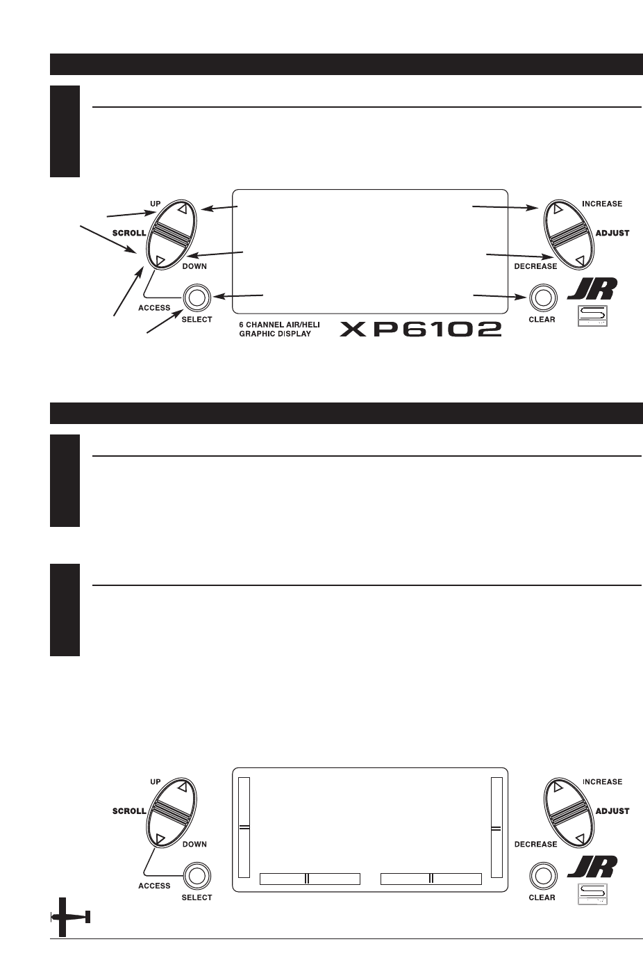
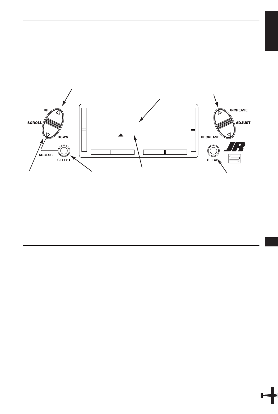
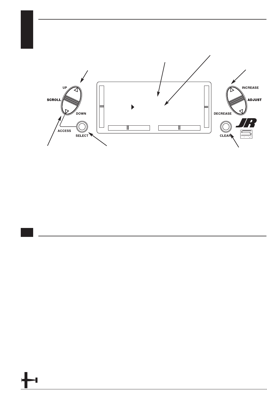
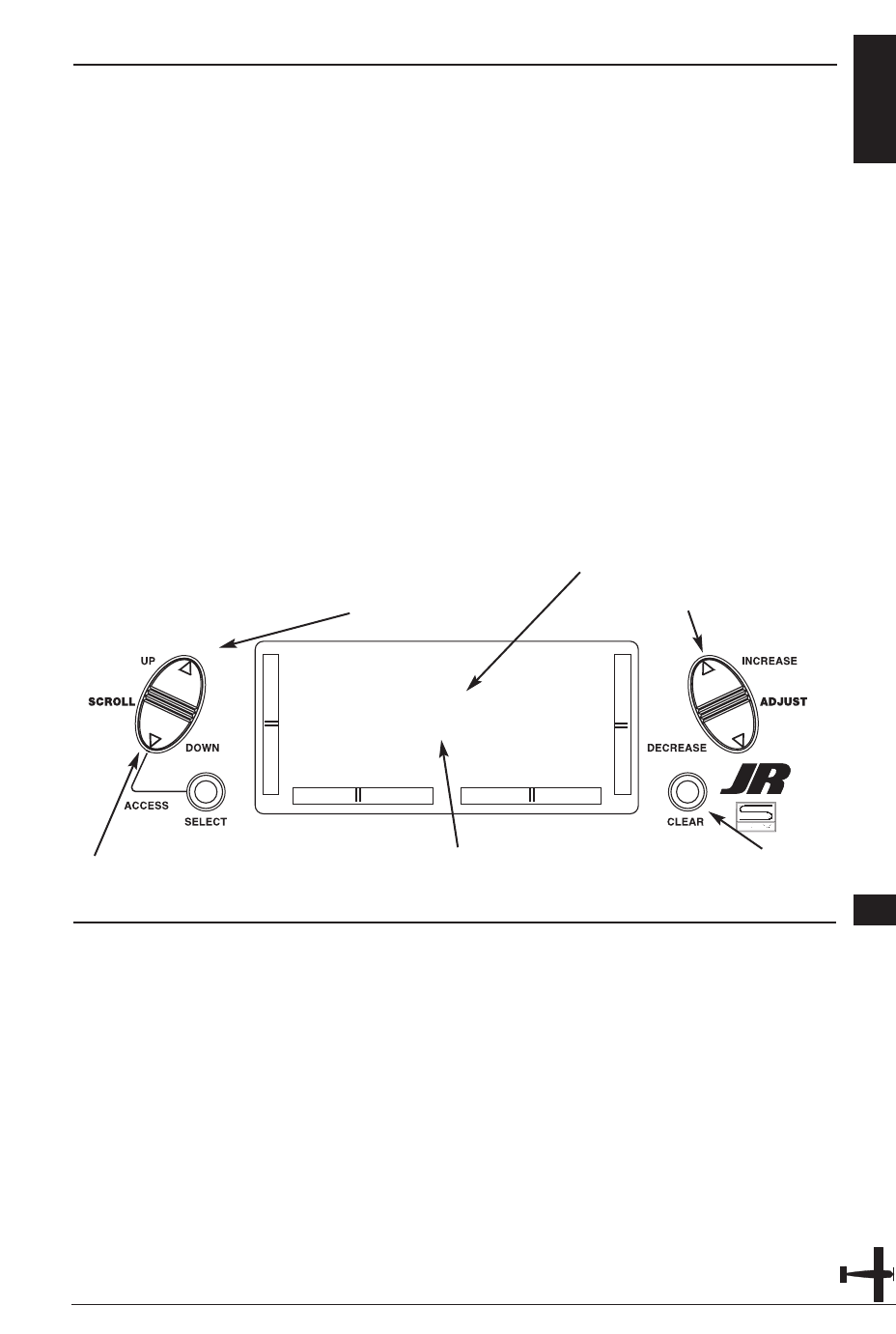
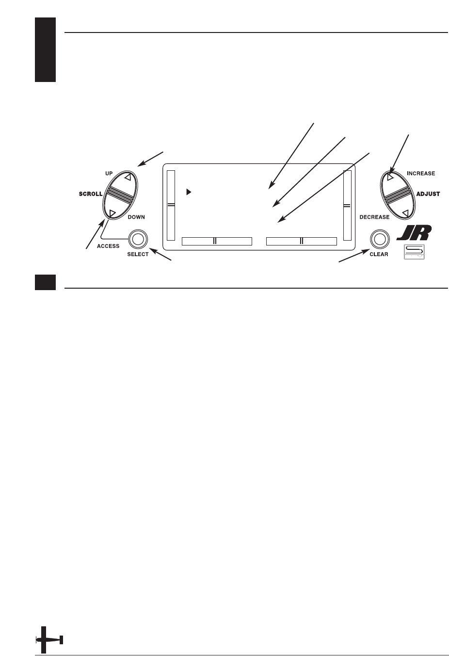
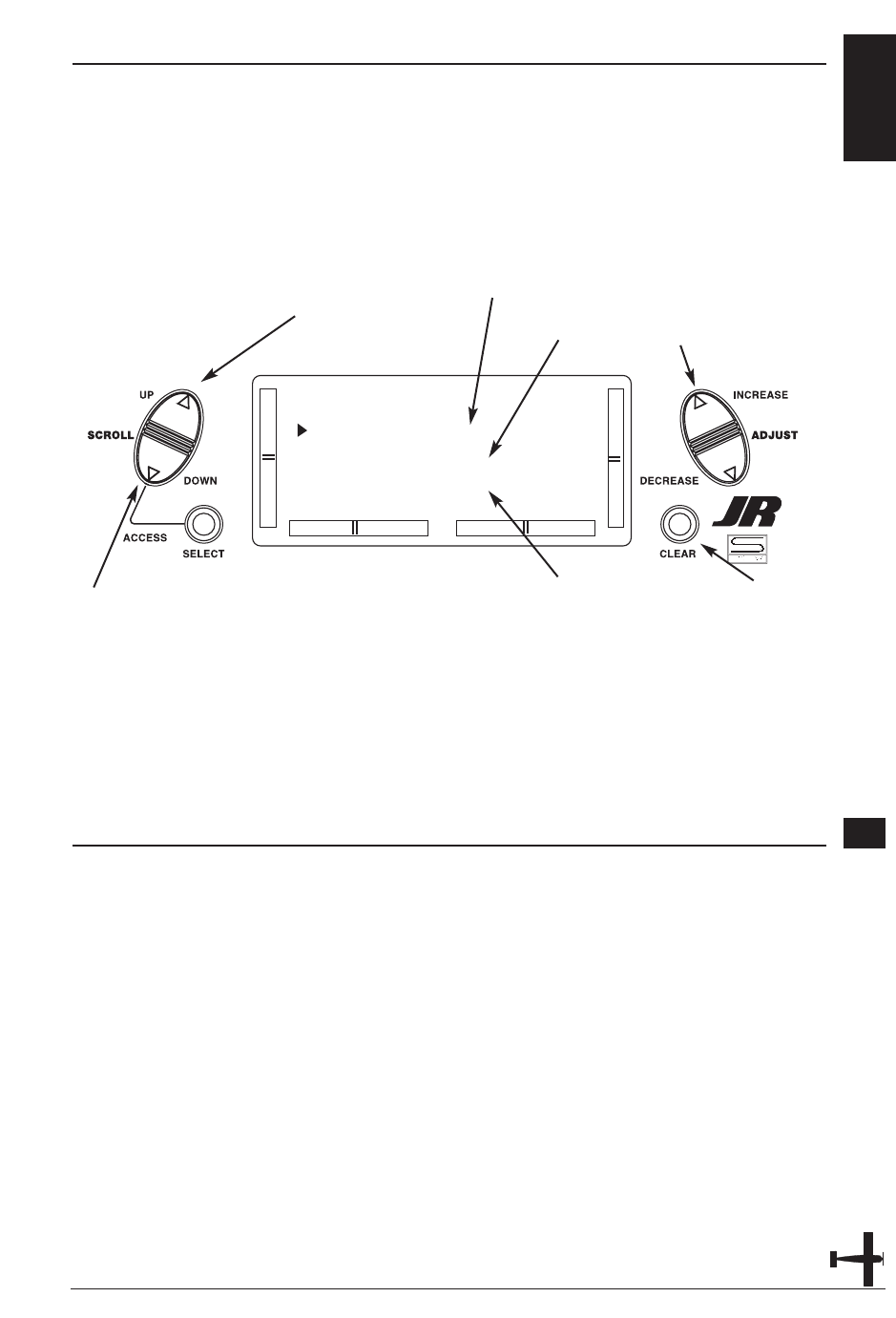
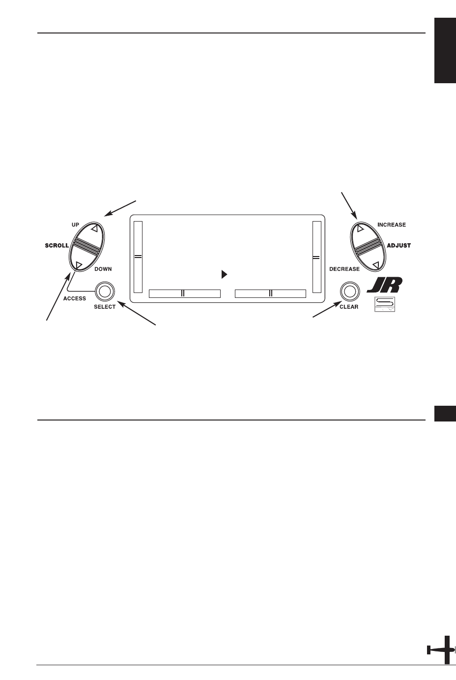
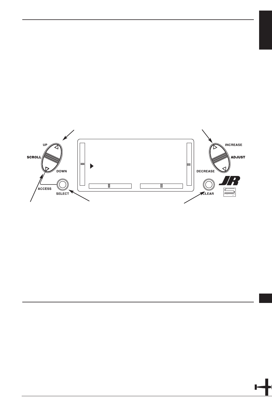
3KEY INPUT AND DISPLAY
The Function Selection keys are used to
move up and down through the
functions.The Channel key is used to
advance the channel or function selected.
The Increase and Decrease keys are used
to make changes in the selected functions.
CHAPTER 3: INPUT MODE AND FUNCTION • AIRPLANE
16 XP6102 - Airplane Manual
4.1 BATTERY ALARM AND DISPLAY
When the transmitter voltage drops
below 9.0 volts DC, the display flashes
“BATT LOW” and an alarm sounds.
If you are flying when this occurs, land
immediately.
CHAPTER 4: ALARM AND ERROR DISPLAY • AIRPLANE
4.2 BACKUP ERROR DISPLAY
All preprogrammed data is protected by a
five-year lithium battery that guards
against main transmitter battery failure.
Should the lithium battery fail, the display
will indicate BACK ERROR. If this occurs,
it will be necessary to replace the lithium
battery and reprogram all data. All
transmitter programs will return to the
factory default settings, and the data you
have input will be lost. When it becomes
necessary to replace the lithium back-up
battery, contact JR Horizon Service
Center. Due to the possibility of extensive
damage caused by improper removal or
replacement, only JR Horizon Service
Center is authorized to make this change.
BACK ERROR
Up
Down
Select
Increase
Decrease
Clear/Store
Press both keys to
enter or exit the
function mode.
Function Keys
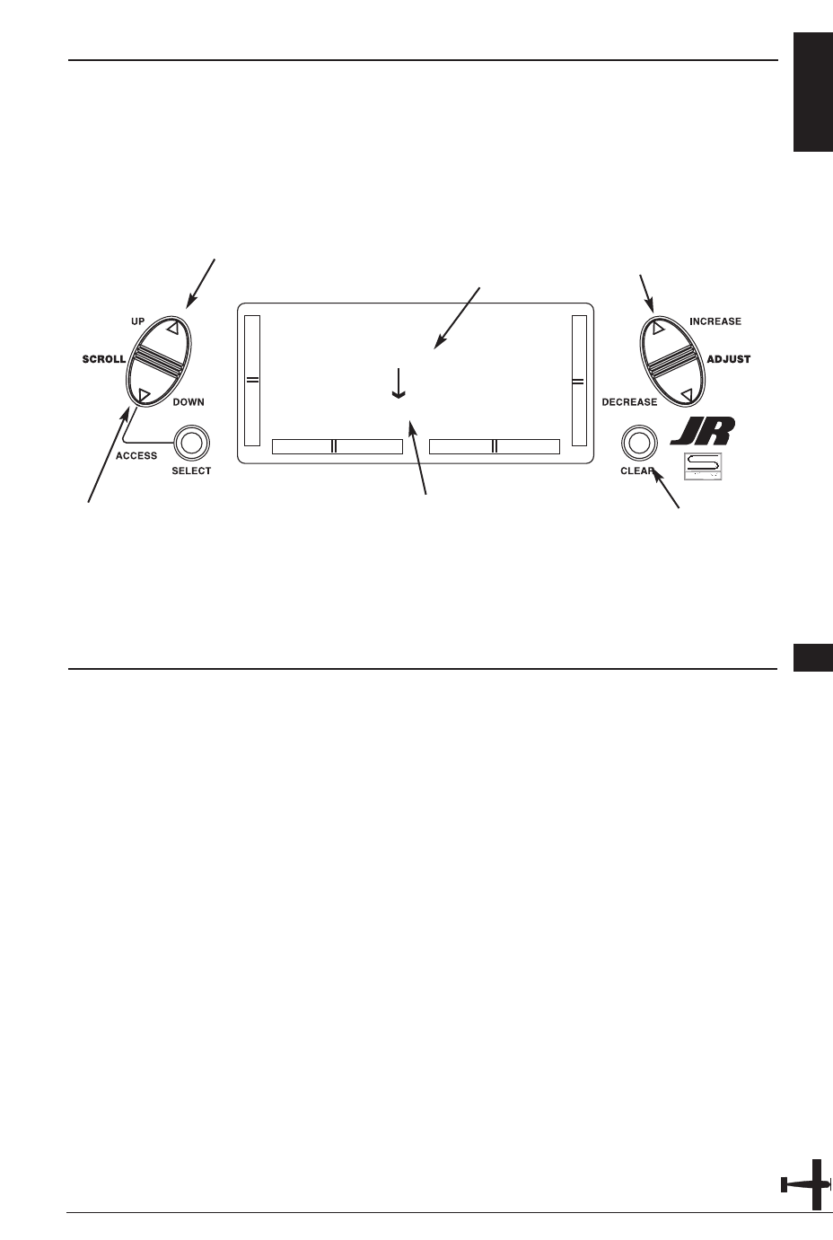
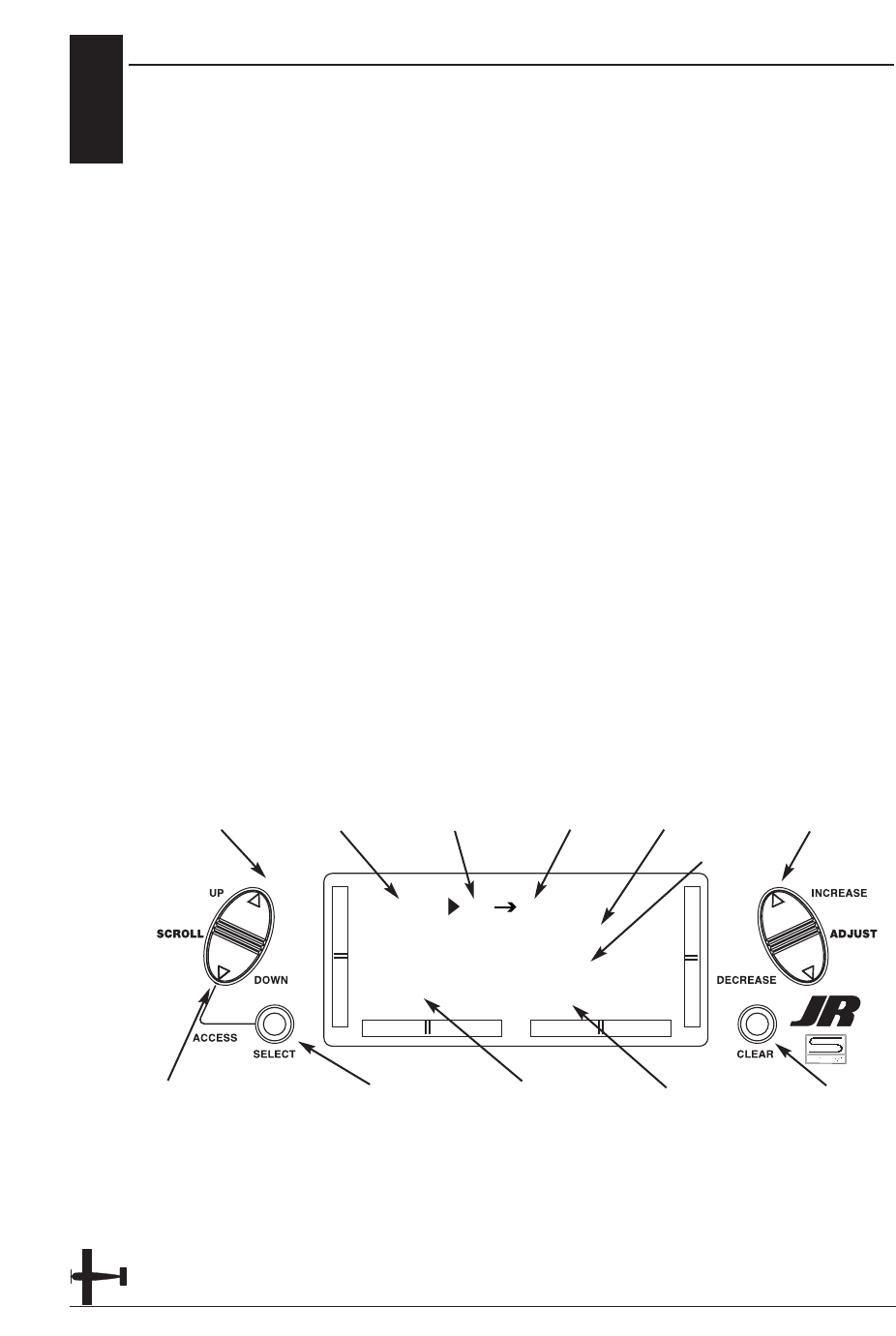
CHAPTER 5: SYSTEM MODE • AIRPLANE
NORMAL MODE 5.1
When the power switch is in the On
position, the display will read as follows:
17XP6102 - Airplane Manual
[MODEL SEL]
#4 PLANE SPCM
ALPHA 40
TOTAL T 0:05:27
To enter and exit the System mode, press
simultaneously then turn on the power switch.
To enter and exit the Function model, turn on
the power switch, then press simultaneously.
Elevator Trim
Aileron Trim
Rudder Trim
Throttle Trim Modulation Type
Model Type
Model Number
Transmitter
"On Time"
Model Name
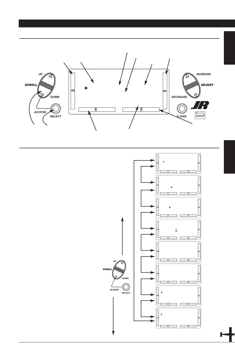
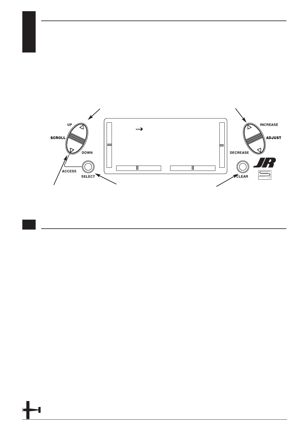
SYSTEM MODE 5.2
To enter the System mode, press the
Down and Select keys simultaneously,
then turn the power switch to the on
position. The display will show the last
active program. Pressing either the Up or
Down key then scrolls through the
functions one by one, according to the
system mode flowchart shown to the right.
Once the appropriate function is
displayed, changes can be made by
pressing the (+) or (-) keys.
System Mode Flowchart
Information pertaining to each function is
explained on the page listed next to the
function name. Functions will appear in
the same order they are shown on
this chart.
Accessing the System Mode
1. Press the Down and Select keys
simultaneously.
2. Move the power switch to the On
(upper) position.
3. Use either the Up or Down key to
scroll through the menu and access the
applicable function.
[MODEL SEL]
#4 PLANE SPCM
ALPHA .40
TOTAL T 0:05:27
[MODEL NAME]
#5 PLANE SPCM
ALPHA 40
[MODEL TYPE]
#5 ALPHA 40
AIRPLANE
DATA RESET
[MODEL COPY]
#5 ALPHA 40
#6 PLANE SPCM
[MODULATION]
#5 ALPHA 40
SPCM
[TRAINER]
#5 ALPHA 40
NORMAL
[SWITCH SEL]
D/R INDIVID
GEAR RIGHT SW
FLAP FLAP LVR
[WING TYPE]
FLAPERON OFF
ELEVON OFF
V-TAIL OFF
Model
Selection
pg 18
Model
Name
Entry
pg 19
Model
Type
pg 20
Model
Copy
pg 21
Modu-
lation
pg 22
Trainer
pg 23
Switch
Select
pg 24
Wing
Type
pg 25
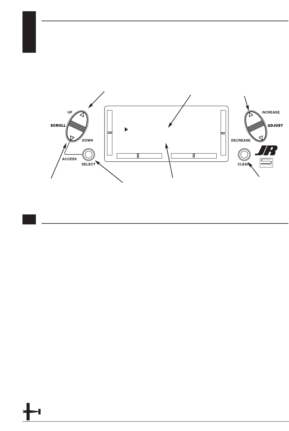
5.3 MODEL SELECTION
The XP6102 system offers memory for ten
completely separate models. Therefore,
it is possible to have a mixture of
helicopter and airplane setups retained
in memory. It is also recommended that
the Model Name Entry function be used
in conjunction with each model setup.
Another very useful function of the Model
Selection function is the ability to set
one aircraft up several different ways.
This is helpful when multi-task
performance is desired.
18 XP6102 - Airplane Manual
[MODEL SEL]
#4 PLANE SPCM
ALPHA 40
TOTAL T 0:05:27
Model Name (if programmed)
Model Number and Type
Toggle between Model
and Timer
Clear Timer (when selected)
Go to Model Name menu
Go to Wing Type menu
Change model selection
Accessing the Model Select Function
1. While pressing the Down and Select
keys, switch the transmitter to the On
position to enter the Model Select mode.
2. Model Select will be displayed on the
upper left portion of the LCD. If not,
press the Up or Down key until MODEL
SEL is displayed.
3. Pressing the (+) or (-) key will select
among each of the ten models available.
Notice that as each model is selected, its
name appears in the LCD.
4. Once the desired model is displayed on
the left, pressing the Down and Channel
keys simultaneously will exit the Model
Selection function and establish the
model displayed as the new current
model.
5. Press the Select key to select the timer
function to clear the Total Timer. Press
the Clear key to clear the Total timer.
6. Press the Down key to access the
WING TYPE function.
7. Press the Up key to access the MODEL
NAME function.
8. Press the Down and Select keys
simultaneously to exit the MODEL SEL
function.
MODEL NAME ENTRY 5.4
The XP6102 allows an 8-digit name to be
input for each of the ten models available.
The current model will be displayed in the
Normal display.
19XP6102 - Airplane Manual
Accessing the Model Name Entry Function
1. While pressing the Down and Select
keys, switch the transmitter to the On
(upper) position to enter the Model
Setup mode.
2. press the Up or Down key until
MODEL NAME is displayed.
2. Press either the Up or Down key to
select the first character for the model
name.
4. Press the Select key to advance the
character selection to the next character.
5. Repeat this procedure until all eight
characters have been selected.
6. Press the Down key to access the
MODEL SEL function.
7. Press the Up key to access the MODEL
TYPE Selection function.
8. Press the Down and Select keys
simultaneously to exit the MODEL
NAME function.
[MODEL NAME]
#5 PLANE SPCM
ALPHA 40
Model name being
programmed
Model Number and Type
Select character Reset selected
character to blank
space
Go to Model Type menu
Go to Model Select menu
Change selected
character
5.5 MODEL TYPE SELECTION
The XP6102 is capable of performing
as a helicopter or airplane radio with
full functions for each.
20 XP6102 - Airplane Manual
Accessing the Type Selection Function
1. While pressing the Down and Select
keys, switch the transmitter to the On
position to enter the Model Setup mode.
2. Press either the Up or Down keys until
MODEL TYPE is displayed in the left
portion of the LCD.
3. Pressing either the (+) or (-) key will
change the type of model.
4. Press the Select key to move the cursor
to the Data Reset position.
5. Press the Clear key to reset the memory
to the factory defaults.
6. Press the Down key to access the
MODEL NAME function.
5. Press the Up key to access the MODEL
COPY function.
6. Press the Down and Select keys
simultaneously to exit the MODEL TYPE
function.
[MODEL TYPE]
#5 ALPHA 40
AIRPLANE
DATA RESET
Model Type function
Model Number and Name
Toggle between Model
Type and Data Reset Reset Data (when selected)
Go to Model Copy menu
Go to Model Name menu
Change model
type selection
21XP6102 - Airplane Manual
MODEL COPY FUNCTION 5.6
The Copy Selection function enables you
to copy all of the settings of the current
model to another model within the same
transmitter. This is very useful when setting
up one aircraft several different ways or
when trying an alternative setup of your
current model.
Accessing the Model Copy Function
1. While pressing the Down and Select
keys, move the transmitter’s power
switch to the On position.
2. Press either the Up or Down key until
MODEL COPY appears on the top left
of the LCD.
3. The upper number that appears is the
current model. This is important to note
as only the current model will be the
copied. Press the (+) or (-) keys to select
the desired program (lower number) to
copy the current model to.
4. Next, press the Clear key. The current
model will then be copied to the
selected model.
Note: Always make sure that the
accepting model is either free of
input or one which you no longer
want to retain in your transmitter’s
memory. Once the copying process
has been completed, the information
of the accepting model is lost and the
current model is input as the new
data.
5. Press the Up key to access the
MODULATION function.
6. Press the Down key to access the
MODEL TYPE function.
7. Press the Down and Select keys
simultaneously to exit the MODEL
COPY function.
[MODEL COPY]
#5 ALPHA 40
#6 PLANE SPCM
Model number to
be copied to
Model number and name
to be copied
Perform copy
function
Go to Modulation menu
Go to Model Type menu
Change model to
copy to
22 XP6102 - Airplane Manual
5.7 MODULATION SELECTION
The Modulation Selection function
enables your XP6102 to transmit to a
variety of JR receivers. You can select from
either S-PCM or from linear PPM (Pulse
Position Modulation [FM]).
Accessing the Modulation Function
1. Move the power switch to the On
position while pressing the Down and
Select key to access the System mode.
2. Press either the Up or Down key until
MODULATION appears at the top of the
LCD.
3. Press either the (+) or (-) keys to change
the modulation type.
4. Pressing the Clear key will also reset
the modulation selection to the factory
preset S-PCM.
5. Press the Down key to access the
MODEL COPY function.
6. Press the Up key to access the
TRAINER function.
7. To exit the MODULATION function,
press the Down and Select keys
simultaneously.
Note: In the normal display, the selected
modulation type will appear in the
upper right of the LCD.
[MODULATION]
#5 ALPHA 40
SPCM
Modulation
Model Number and Name
Select S-PCM
Go to Trainer menu
Go to Model Copy menu
Toggle between
PPM and S-PCM
23XP6102 - Airplane Manual
TRAINER FUNCTION 5.8
The XP6102 offers a programmable trainer
function with three trainer options:
Normal mode - In this mode the
transmitter acts as a conventional buddy-
box system. The transmitter can be used as
a slave or as a master: however in this
mode, the reversing switches and trims
must be adjusted so the slave transmitter
matches the master transmitter. In normal
mode, when the trainer switch is
activated, the student has control of all
functions and switches.
Pilot Link - When pilot link mode is used
with the master transmitter, it allows the
slave transmitter to be adjusted to factory
defaults. The slave transmitter can simply
be programmed in a model memory not
being used and reset to factory defaults,
thus preventing the need to synchronize
the trims and reversing switches on the
slave transmitter.
Also, when Pilot Link is used, the student
only has control of the 4 basic channels
(throttle, aileron, elevator, rudder) while
the trainer (master) retains control of all
other functions like gear, dual rate,
programmed mixes, etc. This allows a
pilot to have a test flight on a more
complex airplane without having to
remember complex switch positions.
Pilot Link + Slave - This mode is used
only when the XP6102 is being used as a
slave transmitter and the other Master
transmitter has a Pilot Link program
active. By selecting Pilot Link + Slave the
transmitter is automatically in the correct
programming mode to work as a slave in
conjunction with another Pilot Link
equipped transmitter.
Accessing the Trainer Function
1. Move the power switch to the On
position while pressing the Down and
Select keys to access the System mode.
2. Press either the Up or Down key until
TRAINER appears at the top of the LCD.
3. Press either the (+) or (-) keys to change
the Trainer Type type.
4. Pressing the Clear key will return the
trainer function to the "normal" setting.
5. Press the Down key to access the
MODULATION function.
6. Press the Up key to access the SWITCH
SEL function.
7. To exit the TRAINER function, press the
Down and Select keys simultaneously.
Note: The slave transmitter must always
be in PPM modulation to operate.
Pilot Link + Slave automatically selects
PPM modulation when activated.
With other transmitters it will be
necessary to be in PPM mode for the
XP6102 to operate properly as a slave.
[TRAINER]
#5 ALPHA 40
NORMAL
Trainer mode selected
Model number and name
Return to Normal mode
Go to Switch Select menu
Go to Modulation menu
Change trainer
mode
5.9 SWITCH SELECT
The XP6102 allows the several options to
be programmed for the dual rate, gear and
flap switches.
Aileron and elevator dual rates can be
programmed to be individually selected
via it's own switch (Individ) or the aileron,
elevator and rudder functions can be
combined to operate from one of 4
switches.
The gear channel can be programmed to
operate on one of 4 switched or rockers
or it can be inhibited, helpful for some
types of mixing. Plus the flap channel can
be programmed to operate from switches
or levers.
24 XP6102 - Airplane Manual
[SWITCH SEL]
D/R INDIVID
GEAR LEFT SW
FLAP RIGHT SW
Gear indicator
Dual Rate indicator
Reset selection to default
Go to Wing Type menu
Go to
Trainer menu
Switch selection
Accessing the Modulation Function
Dual Rates
D/R INDIVID (default) - In this mode
the aileron and elevator rates are
independently selected using the
ELEV D/R and AILE D/R switches.
Note: In this mode the rudder D/R is
always in the 0 position and is not
selectable. This is the default setting.
COM AILE - In this mode the aileron,
elevator and rudder dual rates are
combined on the AILE D/R switch.
COM ELEV - In this mode the aileron,
elevator and rudder dual rates are
combined on the ELEV D/R switch.
COM R-SW - In this mode the aileron,
elevator and rudder dual rates are
combined on the upper right (flap) switch.
COM L-SW - In this mode the aileron,
elevator and rudder dual rates are
combined on the upper left (gear) switch.
Gear Channel
LEFT SW (default) - The gear channel
operates from the left upper (gear) switch.
AILE D/R - The gear channel operates
from the aileron dual rate switch.
ROCKER - The gear channel operates
from the right rocker switch and offers
three positions.
INHIBIT - The gear channel is inhibited
and is centered making it useful as a slave
channel for mixing.
RIGHT SW - The gear channel operates
from the right upper (flap) switch.
Flap Channel
RIGHT SW (default) - The flap
channel operates from the right upper
(flap) switch.
LEFT SW - The flap channel operates from
the left upper (gear) switch.
ELEV D/R - The flap channel operates
from the elevator dual rate switch.
FLAP LVR - The flap channel operates
from the left flap lever and is proportional.
Flap indicator
Select function
WING TYPE SELECTION 5.10
There are three different wing types to
choose from; select the one that will best
suit your R/C aircraft. Flaperon, Elevon
and V-Tail are available selections for
Wing Type and will be covered in the
following pages.
25XP6102 - Airplane Manual
[WING TYPE]
FLAPERON OFF
ELEVON OFF
V-TAIL OFF
V-Tail indicator
Flaperon indicator
Return to Default mode
Go to Model Select menu
Go to Switch Select menu
Turn selected
type on or off
Elevon indicator
Definition of Wing Types
Normal- This is used with aircraft with
one servo operating both ailerons. This
mode is the default setting and is active
when the Flaperon, Elevon and V-Tail
modes are off.
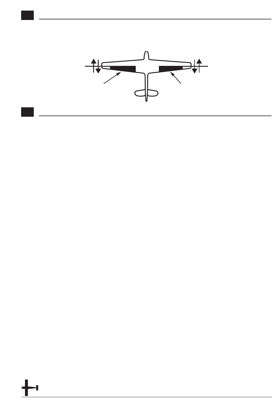
Flaperon- This mode is used when two
servos are used to operated the ailerons.
Flaperons allow each aileron to be
independently adjusted. In addition, they
can be programmed to move in the same
direction for use as flaps or spoilers
Elevon- This mode is used for some types
of delta wing aircraft where the control
surfaces function as both ailerons and
elevators.
V-Tail- Used for V-tailed airplanes.
Note: Some function will be unavailable
when certain functions are active.
With Flaperon active, Elevon will be
unavailable. With Elevon active, both
Flaperon and V-Tail will be
unavailable. Finally, with V-Tail
active, Elevon will be unavailable.
26 XP6102 - Airplane Manual
Flaperon Wing Type Selection
Flaperons allow you to use the existing
ailerons as flaps. The ailerons can be
raised or lowered in unison as flaps, yet
still remain fully operational as the
ailerons of your R/C airplane.
Accessing and Utilizing the Flaperon Wing Type Selection
1. While the Down and Select buttons are
pressed, move the power switch to the
On position to access the System mode.
2. Press either the Up or Down keys until
WING TYPE appears in the upper area
of the LCD.
3. Press either the (+) or (-) key to change
the Flaperon (FLPR) Wing Type
Selection.
Note: For Flaperon, one servo must be
used for each aileron control surface.
4. Plug the left wing aileron servo into the
Auxiliary 1 (AUX 1) port of your JR
receiver. Connect the right aileron servo
into the aileron port (AILE) of your
receiver.
5. Check to make sure that the wing
servos move in the proper direction. For
a right turn, the right aileron should raise
while the left aileron lowers
simultaneously. For a left turn, the
opposite is true; the left aileron should
rise while the right aileron drops. If your
servos are not moving in the direction
just described, use the Servo Reversing
function to reverse the travel direction of
the servo(s) that are moving improperly.
Refer to the Servo Reversing section for
information on how to reverse the travel
direction.
Note: Each servo's travel direction is
adjusted individually through the
Servo Reversing function.
Once the servos achieve their proper
travel direction, adjust their travel volume,
dual rates, sub-trim and aileron
differential.
Note: The applicable channel's left or
right travel adjustment may be made
individually by accessing the Travel
Adjust function. Refer to the Travel
Adjust section of this manual for
more information. The fine
adjustments of your aileron controls
should be made in the Dual-Rate
function. Refer to the Dual-Rate
section for information on how to do
so. You can also adjust the neutral
point of your aileron servos
individually through the use of the
Sub-Trim function. Refer to the Sub-
Trim section of this manual for more
information.
6. The flap lever located on the left face of
the transmitter controls the aileron
movements as flaps.
Note: Differential is offered for the
Flaperon function of your XP6102.
For more information, please refer to
the Differential section of this
manual.
8. Press the Down key to access the
SWITCH SEL function.
9. Press the Up key to access the MODEL
SEL function.
10. Exit the WING TYPE function by
pressing the Down and Select keys
simultaneously.
Connect this servo
to the aileron port
of the receiver
Connect this servo
to the AUX1 port
of the receiver
27XP6102 - Airplane Manual
Elevon Type Selection
Elevon Wing Mixing is available as on
option with your XP6102. This style of
aircraft also employs two wing servos.
However, there is not an elevator present.
Instead, at an elevator stick input, the two
wing servos function in conjunction with
one another to change the pitch
movement of the aircraft. Also, when an
aileron control is given, the two wing
servos move in opposition to one another
to function as ailerons.
Accessing and Utilizing the Elevon Type Selection
1. While the Down and Select keys are
pressed, move the power switch to the
On position to access the System mode.
2. Press either the Up or Down key until
WING TYPE appears on the LCD.
3. Press the Select key to select the Elevon
function.
4. Press either the (+) or (-) key to change
the Elevon Wing Type function.
Note: The Elevon function requires one
servo for each elevon, i.e. a separate
servo for each wing half.
5. Plug the left elevon servo to the aileron
(AILE) of your JR receiver. Connect the
right elevon servo into the elevator
(ELEV) port of your receiver.
6.Check to make sure the servos move in
the proper direction. When an input is
given from the elevator stick, they
should move in unison to achieve the
proper up/down elevator command. If
your servos do not move as described
above, use the Servo Reversing function
to reverse the travel direction.
Note: Each servo's direction is adjusted
individually through the Servo
Reversing function. For more
information, refer to the Servo
Reversing section in this manual.
7. Once the servos direction has been
set, adjust their travel direction, travel
volume, dual rates, sub-trim and
aileron differential.
Note: The applicable channel's left or
right, up or down travel adjustments
can be made individually. Refer to
the Travel Adjust section in this
manual for more information.
8. Relative to the note above, each servo's
travel volume is automatically reduced
to 75% of the operating range. This is to
ensure that the servo does not operate
beyond its capabilities. Failure to
observe extreme caution when adjusting
the value for the elevon servos may
result in damage to the servos by over
traveling.
Note: Fine adjustments of the elevons
should be made in the Dual-Rate
function. For more information, refer
to the Dual-Rate section in this
manual. You can also adjust the
neutral point of your elevon servos
individually using the Sub-Trim
function as described in the Sub-Trim
section of this manual. Differential is
offered for the elevon function of
your XP6102. For more information,
refer to the Differential Aileron
Mixing section of this manual.
9. Press the Down key to access the
SWITCH SEL function.
10. Press the Up key to access the
MODEL SEL function.
11. To exit the WING TYPE function, press
the Down and Select keys
simultaneously.
Connect this servo
to the elevator port
of the receiver
Connect this servo
to the aileron port
of the receiver

28 XP6102 - Airplane Manual
V-Tail Type Selection
Section in progress
Accessing and Utilizing the V-Tail Type Selection
1. While the Down and Select keys are
pressed, move the power switch to the
On position to access the System mode.
2. Press either the Up or Down key until
WING TYPE appears on the LCD.
3. Press the Select key to select the Elevon
function.
4. Press either the (+) or (-) key to change
the V-Tail Wing Type function.
Note: The V-Tail function...
5. Plug the servo...
6.Check to make sure the servos move in
the proper direction. When an input is
given from the elevator stick, they
should move in unison to achieve the
proper up/down elevator command. If
your servos do not move as described
above, use the Servo Reversing function
to reverse the travel direction.
Note: Each servo's direction is adjusted
individually through the Servo
Reversing function. For more
information, refer to the Servo
Reversing section in this manual.
7. Once the servos direction has been
set, adjust their travel direction, travel
volume, dual rates, sub-trim and
aileron differential.
Note: The applicable channel's left or
right, up or down travel adjustments
can be made individually. Refer to
the Travel Adjust section in this
manual for more information.
8. Relative to the note above, each servo's
travel volume is automatically reduced
to 75% of the operating range. This is to
ensure that the servo does not operate
beyond its capabilities. Failure to
observe extreme caution when adjusting
the value for the elevon servos may
result in damage to the servos by over
traveling.
Note: Fine adjustments of the elevons
should be made in the Dual-Rate
function. For more information, refer
to the Dual-Rate section in this
manual. You can also adjust the
neutral point of your elevon servos
individually using the Sub-Trim
function as described in the Sub-Trim
section of this manual. Differential is
offered for the elevon function of
your XP6102. For more information,
refer to the Differential Aileron
Mixing section of this manual.
9. Press the Down key to access the
SWITCH SEL function.
10. Press the Up key to access the
MODEL SEL function.
11. To exit the WING TYPE function, press
the Down and Select keys
simultaneously.
Connect this servo
to the rudder port
of the receiver
Connect this servo
to the elevator port
of the receiver
29XP6102 - Airplane Manual
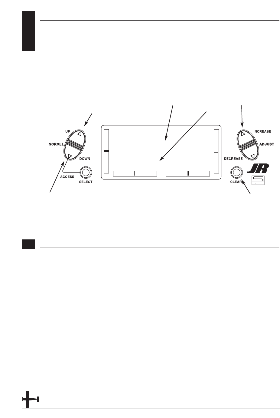
CHAPTER 6: FUNCTIONS (FUNCTION MODE ) • AIRPLANE
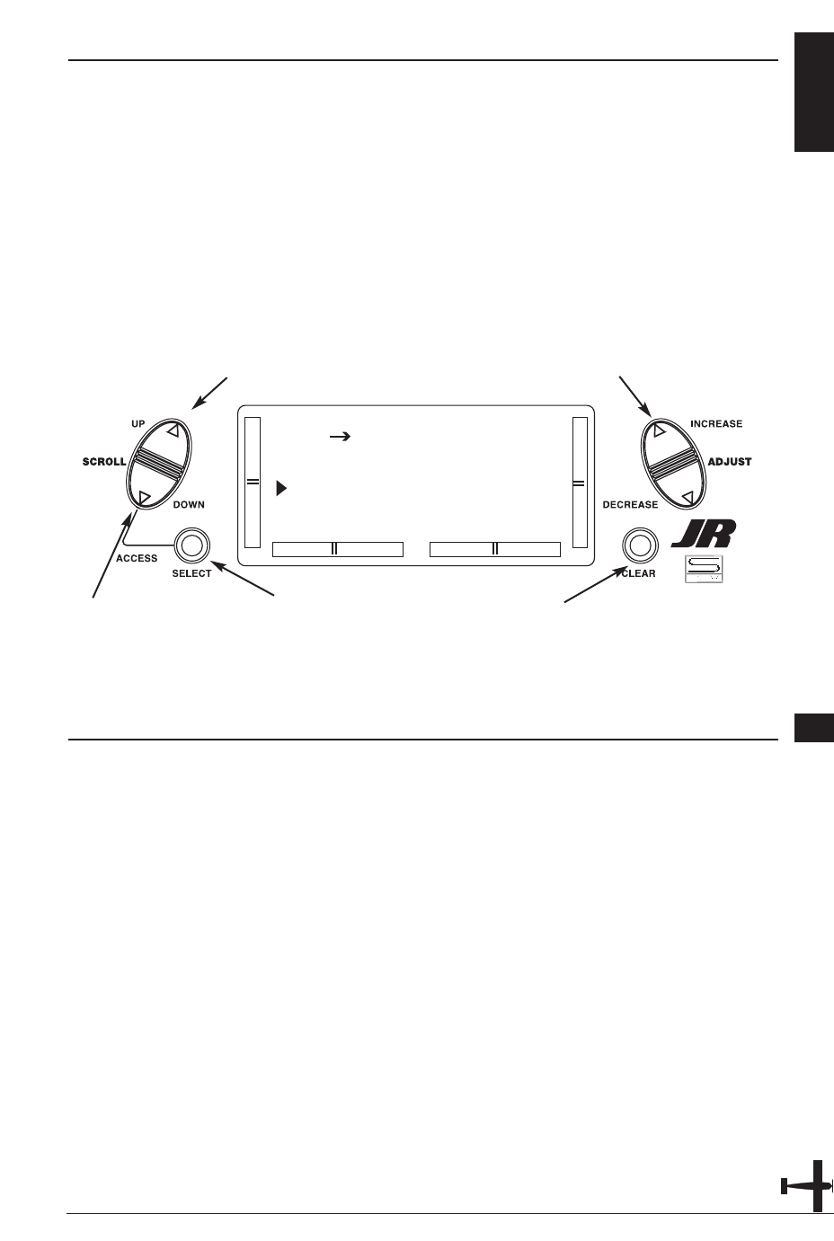
FUNCTION MODE 6.1
To enter the Function mode, switch the
transmitter power switch to the On
position. Press the Down and Select keys
simultaneously, and the display will
show the last active program. Pressing
either the Up or Down key then scrolls
through the functions one by one,
according to the Function Mode
Flowchart shown on the right. Once the
appropriate function is displayed, changes
can be made by pressing the (+) or (-)
Accessing the Mode Function
1. Move the power switch to the On
position.
2. Press the Down and Select keys
simultaneously.
[D/R & EXP]
AILE POS 0
EXP LIN
D/R 100%
Dual Rate and Expo pg 30
[TRAVEL ADJ]
THRO AILE
H100% L100%
L100% R100%
Travel Adjustment pg 33
[THRO CUT]
INHIBIT
Throttle Cut pg 36
[FAIL SAFE]
TH HLD AI HLD
EL HLD RU HLD
GE HLD FL HLD
Fail Safe pg 40
[REVERSING SW]
THR:N AIL:N
ELE:N RUD:N
GEA:N FLA:N
Reversing Switches pg 31
[ELE F MX] ON
E-DN 0%
E-UP 0%
SW ALWAYS ON
Ele➔F Mix pg 34
[FLAP SYSTEM]
FLAP DN100%
ELEV 0%
Flap System pg 37
1
3
5
2
4
6
Servo Travel Screen pg 41
[SUB TRIM]
TH 0 AI 0
EL 0 RU 0
GE 0 FL 0
Sub Trim pg 32
[AIL RUD MIX]
ON
VAL 0%
SW ALWAYS ON
Ail➔Rud Mix pg 35
[MX1] THR THR
ON OFFSET 0
0% 0%
SW ALWAYS ON
Programmable Mix 1-4 pg 38
3. Use either the Up or Down to scroll
through the menu and access the
applicable function.
keys. To select another channel of a
particular function, press the Select key.
The Function mode is the most often used
system to input data.
Function Mode Flowchart
Information pertaining to each function is
explained on the page listed next to the
function name. Functions will appear in
the same order they are shown on this
chart.
Navigate forward
through menus
Navigate backwards
through menus
6.2 DUAL RATES AND EXPONENTIAL
Dual rates are available for the aileron,
elevator and rudder channels of your R/C
aircraft. There is also an automatic dual
rate setting to link your aileron, elevator,
and rudder dual rates to the flight model
switch. This automatic Dual-Rate function
is discussed in a separate section that
follows. Dual rates may be defined as the
ability to vary the travel or throw rate of a
servo from a switch. Due to the differing
travel rates, you will find that the
sensitivity of the control either increases
or decreases accordingly. A higher rate, or
travel, yields a higher overall sensitivity.
You may find it easier to think
of the Dual-Rate function as double-rates
or half-rates.The Dual-Rate function works
in conjunction with the Exponential
function to allow you to precisely tailor
your control throws. You may want to
consult the section defining exponential
for further information.
30 XP6102 - Airplane Manual
Accessing the Dual Rate and Exponential Function
1. Place the transmitter power switch in
the on position.
2. Access the Function mode by pressing
the Down and Select keys
simultaneously.
3. Press either the Up or Down key until
D/R & EXP appears in the upper left
corner of the LCD.
4. Press the Channel key until the desired
channel (aileron, elevator, rudder or
automatic dual rates) appears.
5. Select the switch position for which you
want to adjust the rate. The number to
the upper right of the current rate value
on the display indicates the current
position of the Dual-Rate switch for the
channel that you have selected. Either a
0 or a 1 will be shown, corresponding to
the position of the switch. To select the
opposite switch position, move the
appropriate Dual-Rate switch to the
opposite position. The number that
appears above the current rate value
reflects the change.
6. Adjust the rate for the channel and the
switch position just selected. To
decrease the throw rate, press the (-) key.
To increase the throw rate, press the (+)
key. As stated previously, the adjustable
rate is from 0-125% for each switch
position and channel.
7. Press the Up arrow key to access the
REVERSING SW menu.
8. Press the Down arrow key to access the
SERVO TRAVEL SCREEN.
9. Press the Down arrow and Select keys
simultaneously to exit the function
mode.
The amount of travel is adjustable from
0-125% in 1% increments. The factory
setting, or default value, for both the
0 and 1 switch positions is 100%.
Either switch position may be selected as
the low or high rate by placing the switch
in the desired position and adjusting
the value accordingly.
[D/R & EXP]
AILE POS 0
EXP LIN
D/R 100%
Go to Reversing SW menu
Go to Servo Travel Screen Select channel, EXP or D/R
Change channel or value
Reset selection to default

SERVO REVERSING 6.3
The Reverse Switch function is an
electronic means of reversing the throw
of a given channel (servo). All six channels
of the XP6102 offer reversible servo
direction. This will ease setup during
the servo installation into your aircraft.
31XP6102 - Airplane Manual
Accessing the Servo Reversing Function
1. Place the transmitter switch in the on
position.
2. Access the Function mode by pressing
the Down and Select keys
simultaneously.
3. Press either the Up or Down key until
the REVERSING SW appears in the
upper portion of the LCD.
4. Using your transmitter’s control sticks,
switches and potentiometers, move the
control surfaces of your aircraft. Note
the travel direction of each of the
corresponding control surfaces.
5. After you have determined which
channel(s) need to have the throw
directions reversed, use the Select key to
call up the appropriate channel.
6. Press either the (+) or (-) keys to change
the travel direction of the servo. Pressing
the Clear key returns the travel direction
to Normal.
7. You can observe the change in the
travel direction by moving the
appropriate control at this time.
8. Access the D/R & EXP function by
pressing the Down key.
9. Access the SUB TRIM function by
pressing the Up key.
10. Exit the Servo Reversing function by
pressing the Down and Select keys
[REVERSING SW]
THR:N AIL:N
ELE:N RUD:N
GEA:N FLA:N
Go to Sub Trim menu
Go to D/R & Exp menu
Change servo direction
Reset direction to normal
Select channel to reverse
6.4 SUB TRIM
The Sub Trim Adjustment function allows
you to electronically fine-tune the
centering of your servos. Individually
adjustable for all six channels with a
range of ±125% (+/-30 degrees servo
travel).
The sub trim functions provides precise
servo arm neutral positioning if rotating
the servo arm will not allow the desired
servo arm position.
32 XP6102 - Airplane Manual
Accessing the Sub Trim Function
1. Place the transmitter power switch in
the On position.
2. To Access the Function mode, press the
Down and Select keys simultaneously.
3. Press either the Up or Down key until
SUB TRIM appears in the upper middle
portion of the LCD.
4. Press the Select key until the desired
channel appears.
5. Press the (+) or (-) key to establish the
desired amount and direction of Sub-
Trim.
Caution: Do not use excessive sub-trim
adjustments since it is possible to
overrun your servo’s maximum Sub
Trim. Remember that it is a trim
convenience function. It is not
intended to take the place of the
proper mechanical trim adjustments
that are necessary on any R/C model.
6. Access the REVERSING SW function by
pressing the Down key.
7. Access the TRAVEL ADJ function by
pressing the Up key.
8. Exit the SUB TRIM function by pressing
the Down and Select keys
simultaneously.
[SUB TRIM]
TH 0 AI 0
EL 0 RU 0
GE 0 FL 0
Go to Travel Adj menu
Go to reversing SW menu Select channel
Change value
Reset selection to default
TRAVEL ADJUST 6.5
The purpose of Travel Adjust is to offer
you precise servo control deflection in
either direction of servo operation. The
XP6102 offers travel adjust for all six
channels. The Travel Adjust range is from
0-150% (0 degrees to 60 degrees) from
neutral, or center, and it can be adjusted
for each direction individually. The factory
default (Data Reset) value is 100% for
each direction of servo travel.
33XP6102 - Airplane Manual
Accessing the Travel Adjust Function
1. Place the transmitter power switch in
the On position.
2. Access the Function mode by pressing
the Down and Select keys
simultaneously.
3. Press either the Up or Down key until
TRAVEL ADJ appears in the upper
portion of the LCD.
4. Press the Select key until the desired
channel is highlighted.
5. Move the appropriate control stick
(lever, switch, etc) to the right or left of
center to the direction of travel you want
to adjust. An arrow to the left of the
travel adjust value will reflect the current
position to be adjusted.
6. After the control stick or switch is
placed in the direction of travel to be
adjusted, press the (+) or (-) key until the
proper amount of servo travel is shown
on the LCD. Press the (+) key to increase
the amount of servo travel. Press the (-)
key to decrease the amount of servo
travel.
7. Follow the same procedure for the
remaining channels.
8. Access the SUB TRIM function by
pressing the Down key.
9. Access the ELE ➔F MX function by
pressing the Up key.
10. Exit the TRAVEL ADJ function by
pressing the Down and Select keys
[TRAVEL ADJ]
THRO AILE
H100% L100%
L100% R100%
Go to Ele➔ F MX menu
Go to Sub Trim menu
Change value
Reset value to normal
Select channel to adjust
6.6 ELEVATOR TO FLAP MIXING
When this system is active and a value of
flaps is input, the flaps will be deflected
each time the elevator stick is used. The
actual flap movement is adjustable for
both up and down elevator. The most
frequently used application is up
elevator/down flaps and down elevator/up
flaps. When used in this manner, the
aircraft pitches much more quickly than
normal. The upper-most position of the
Flap Mixing switch activates the Elevator-
to-Flap Mixing circuitry.
34 XP6102 - Airplane Manual
Accessing the Elevator to Flap Function
1. Place the transmitter power switch in
the On position.
2. Access the Function mode. To do so,
press the Down and Select keys
simultaneously.
Press either the Up or Down key until
ELE ➔F MX appears in the upper
portion of your LCD.
3. Move the elevator stick in the direction
you want to mix with flaps.
Note: The position indicator will reflect
this change by highlighting the up or
down arrow.
5. Press the (+) or (-) key to increase or
decrease the amount of flaps to be
mixed. If you want to reverse the flap
travel, press the Clear key, bringing the
mixing value to the factory default (0%),
and increase the value using the
opposite key (+) or (-) from the key
originally selected.
6. Once you have adjusted the first
mixing position (up or down), place the
elevator stick in the opposite direction
and follow Step 5 above to adjust the
second elevator mixing value.
7. Access the switch position by pressing
the Select key. Use the (+) or (-) keys to
select from the one of six switches, or
from always on.
8. Access the TRAVEL ADJ function by
pressing the Down key.
9. Access the AIL ➔RUD MIX Mixing
function by pressing the Up key.
10. Exit the ELE ➔F MX function by
pressing the Down and Channel keys
simultaneously.
[ELE F MX] ON
E-DN 0%
E-UP 0%
SW ALWAYS ON
Go to Go to Ail ➔ Rud Mix menu
Go to Travel Adj menu Change selection
Change value/Select switch
Reset selection to default
AILERON TO RUDDER MIXING 6.7
This form of mixing is designed so that
when input to the aileron stick is given,
the rudder servo will also move,
eliminating the need to coordinate these
controls manually.
When adjusting, if an opposite mixing
direction of the rudder servo is required,
simply press the (+) or (-) keys to change
the mixing value from a (+) to (-) or a
(-) to a (+). This will reverse the mixing
direction of the rudder from its original
direction. The switch used to activate this
mix can also be selected as explained
below. The factory default is always on
with a value of 0%.
35XP6102 - Airplane Manual
Accessing the Aileron to Rudder Mixing Function
1. Place the transmitter power switch in
the On position.
2. Access the Function mode. To do so,
press the Down and Select keys
simultaneously. Press either the Up or
Down key until AIL ➔RUD MIX
appears in the center portion of your
LCD.
3. Press the (+) or (-) key to increase or
decrease the amount of rudder to be
mixed with aileron. If you want to
reverse the Rudder Mix direction, press
the Clear key, bringing the mixing value
to the factory default (0%), and increase
the value using the opposite key (+) or (-
) from the key originally selected.
4. Press the Select key to access the
switch assignment function.
5. Press the (+) or (-) key to select the
desired switch/function to activate the
Aileron-to-Rudder Mixing function.
6. Access the ELE ➔FLP MX mixing
function by pressing the Down key.
7. Access the THRO CUT function by
pressing the Up key.
8. Exit the AIL ➔RUD MIX function by
pressing the Down and Select keys
simultaneously.
[AIL RUD MIX]
ON
VAL 0%
SW ALWAYS ON
Go to Ele ➔ Flp Mx menu
Go to Throttle Cut menu
Change selection
Change value/Select switch
Reset selection to default
6.8 THROTTLE CUT SWITCH
This is the function to assign Throttle Cut
switch to the push button located on
upper right front of the transmitter. The
Throttle Cut function is designed to return
the throttle trim to the lowest position
instantly and keep this position while the
button is pressed. This feature is used to
“cut” or stop the engine without changing
the position of digital throttle trim.
36 XP6102 - Airplane Manual
Accessing the Throttle Cut Function
1. Place the transmitter power switch in
the On position.
2. Access the Function mode. To do so,
press the Down and Select keys
simultaneously. Press either the Up or
Down key until THRO CUT appears in
the upper portion of the LCD screen.
3. Use the (+) and (-) keys to change the
value of the Throttle cut function.
Note: Pressing the Clear key will Inhibit
the Throttle Cut, turning it off until it
has been reactivated.
4. Access the FLAP SYSTEM mixing
function by pressing the Down key.
5. Access the AIL ➔RUD MIX function
by pressing the Up key.
6. Exit the THRO CUT function by
pressing the Down and Select keys
simultaneously.
[THRO CUT]
INHIBIT
Go to Ail ➔ Rud Mix menu
Go to Flap System menu Change value
Set function to Inhibit
FLAP SYSTEM 6.9
The Flap System function automatically
couples the elevator to the flaps.
37XP6102 - Airplane Manual
Accessing the Flap System Function
1. Place the transmitter switch in the On
position.
2. Press the Down and Select keys
simultaneously to enter the Function
mode.
3 .Press either the Up or Down key until
FLAP SYSTEM appears in the top of the
LCD.
5. Press the Select key to select the
desired channels to be adjusted.
6. Use the (+) or (-) keys to set the desired
landing mode surface positions.
4. Access the THRO CUT mixing function
by pressing the Down key.
5. Access the MIX 1 function by pressing
the Up key.
6. Exit the FLAP SYSTEM function by
pressing the Down and Select keys
simultaneously.
[FLAP SYSTEM]
FLAP DN100%
ELEV 0%
Go to Thro Cut menu
Go to MX1 menu
Change selection
Change value
Reset selection to default
6.10 PROGRAMMABLE MIXING (1-6)
The XP6102 offers four programmable
mixes to be used for any number of
different purposes. This function allows
mixing any one channel to any other
channel. This mix can remain on at all
times or be switched on and off in flight
using a number of different switches.
Mix numbers 1-3 are of the standard
variety, in that the digital trim for the
master channel only affect the master
channel, and not the slave channel. Mix
number 4 is of the "Trim Include" variety.
This mix is used any time the mix requires
the slave channels trim position to be
varied when the master channels digital
trim position is varied. An example for this
type of mix would be when dual elevator
or dual aileron servos are used and
connected to two separate channels of the
system, rather than using a single channel
with a Y-harness.
Each channel of this radio is identified by
an abbreviated name. The chart below
indicates the channel and its
corresponding abbreviation. The channel
name appearing first is known as the
"master channel" or the channel to which
you want to mix. The second number is
known as the "slave channel" or the
channel that is being mixed into the
master channel. For example, AIL ➔ RUD
would indicate aileron-to-rudder mixing.
Each time the aileron stick is moved, the
aileron will deflect, and the rudder will
automatically move in the direction and
to the value input.
Mixing is proportional, so small inputs of
the master channel will produce small
outputs of the slave channel. Each
programmable mix has a mixing "offset."
The purpose of the mixing offset is to re-
define the neutral position of the slave
channel.
38 XP6102 - Airplane Manual
[MX1] THR THR
ON OFFSET 0
0% 0%
SW ALWAYS ON
Go to Flap System menu
Go to Flap System menu Change selected value
Reset selection to default
Master Channel Slave ChannelMix number
Switch selection Switch condition
Mix percentages
Offset value
Change highlighted selection
THR: Throttle
AIL: Aileron
ELE: Elevator
RUD: Rudder
GEA: Gear
FLA: Flap

39XP6102 - Airplane Manual
Accessing the Programmable Mixing Function
1. Place the transmitter switch in the On
position.
2. Press the Down and Select keys
simultaneously to enter the Function
mode.
3. Press either the Up or Down key until
MIX 1 appears in the LCD.
Selecting the Master and Slave Mixing
Channels
4. Press the (+) or (-) keys to select the
master channel.
5. Press the Select key to move the cursor
to the slave channel position.
6. Press the (+) or (-) keys to select the
slave channel.
7. Press the Select key once. The display
will continue to show the current mixing
channels at the top of the LCD, but now
an arrow will indicate the current stick
position (master) to be adjusted.
Setting the Mixing Values
8. While holding the master stick in the
direction you want to mix, press the (+)
or (-) keys to increase or decrease the
mixing value for the slave channel. The
value in the LCD will change to display
the current mix value selected. Next,
hold the master stick to the other side to
adjust the mix for the other direction.
Setting the Mixing Switch Activation
9. Press the Channel key once again. The
LCD with "ALWAYS ON" indicates the
current switch that this mix is currently
selected to always be active (ON).
Mixing Operation and Switches
Each mixing program can be turned on
and off by a lever or switch. The levers
and switches that can be selected for
program mixing are tabulated at the right
with their abbreviations appearing on the
display and their corresponding positions.
The mix switch options are:
ALWAYS ON
RIGHT FWD
RIGHT REA
LEFT FWD
LEFT REA
AILE D/R
ELEV D/R
Setting the Mixing Channel Offset
1. Press the Select key until offset is
highlighted. The display will show the
current mixing channels at the top of the
LCD, with the word "OFFSET" in the
center of the LCD. The value to the right
is the mixing Offset neutral point,
currently 0.
2. A new value for the offset can be
selected using the (+) or (-) keys. This is
the new neutral point for the slave
channel (Point that the mix is activated).
Press the Clear key to reset the value
back to 0.
3. Press the Down and Select keys
simultaneously to exit the Programmable
Mix function.
With a little practice, programmable
mixing will become easier to
understand. Mixing is only limited
by your imagination.
FAIL SAFE
The Fail-Safe/Hold function is available
only when you use the XP6102 transmitter
in PCM modulations. This function is
designed to help minimize damage to
your aircraft during a loss of signal to the
receiver. The servos either assume the fail-
safe presets or hold their last good signal
position.
As noted earlier, if you are in the PPM
modulation, the Fail-Safe/Hold function
is not applicable. Therefore, the Fail-
Safe/Hold function will not appear on
your LCD screen menu while in the
PPM mode. Refer to the Modulation
Selection section for more information
pertaining to the broadcast signal of
your XP6102 transmitter.
40 XP6102 - Airplane Manual
Accessing the Fail Safe Function
1. Place the transmitter power switch in
the On position.
2. Access the Function mode. To do so,
press the Down and Select keys
simultaneously. Press either the Up or
Down key until FAIL SAFE appears in
the upper portion of the LCD screen.
3. Use the Select key to highlight the
servo function to set.
4. Use the (+) or (-) keys to toggle
between servo hold or setting the servo
position.
5. When using the servo setting position,
move the corresponding control stick to
the position where you want the servo if
the radio enters into the fail safe mode.
Press the Clear key to have the
transmitter memorize the stick position.
6. Repeat steps 4 and 5 until all six
controls have been set.
7. Access the SERVO TRAVEL screen by
pressing the Up key.
8. Access the MIXING FUNCTIONS
function by pressing the Up key.
9. Exit the FAIL SAFE function by pressing
the Down and Select keys
simultaneously.
[FAIL SAFE]
TH HLD AI HLD
EL HLD RU HLD
GE HLD FL HLD
Go to Programmable
Mixing menu
Go to Servo Travel Screen Change from servo
hold to stick selection
Invoke stick selection
Change highlighted selection
6.11
SERVO TRAVEL SCREEN
The Servo Travel Screen is used to verify
the stick movements of the transmitter. It can also be used to verify the mixing
functions have been performed correctly
without the need to turn on the aircraft.
41XP6102 - Airplane Manual
Accessing the Servo Travel Screen
1. Place the transmitter power switch in
the On position.
2. Access the Function mode. To do so,
press the Down and Select keys
simultaneously. Press either the Up or
Down key until the SERVO TRAVEL
screen appears.
3. Move the sticks. The the indicators
correspond to the following:
Indicator 1: Throttle
Indicator 2: Aileron
Indicator 3: Elevator
Indicator 4: Rudder
Indicator 5: Gear
Indicator 6: Flap
4. Access the D/R & EXP screen by
pressing the Up key.
5. Access the FAIL SAFE function by
pressing the Up key.
6. Exit the SERVO TRAVEL screen function
by pressing the Down and Select keys
simultaneously.
1
3
5
2
4
6
Go to Fail Safe menu
Go to D/R & Exp menu
6.12
XP6102 DATA SHEET
42 XP6102 - Airplane Manual
REVERSE SW
THRO
TRAVEL ADJUST
FAIL SAFE (PCM)
SUB TRIM
H %
L %
NORM
•
REV
AILE
L %
R %
NORM
•
REV
ELEV
U %
D %
NORM
•
REV
RUDD
L %
R %
NORM
•
REV
GEAR
+ %
– %
NORM
•
REV
FLAP
U %
D %
NORM
•
REV
AILE
DUAL RATE
•
EXPO
%
%
%
%
ELEV
%
%
%
%
RUDD
%
%
%
%
D/R
EXP
%
%
UP
DOWN
D/R
EXP
0
1
ELEV – FLAP
MIX
%RATE
SW
AILE – RUDD
MIX
%ELEV
FLAP
FLAP
SYSTEM
D/R
GEAR
FLAP
SWITCH
SELECT
FLAPERON
ELEVON
V-TAIL
WING
TYPE
CHANNEL
PROGRAM
MIX
SW +POS
%
%
%
%
–POS OFFSET
%
%
%
%
MIX 1
MIX 2
MIX 3
MIX 4
–
–
–
–
THROTTLE CUT
MODULATION
NOTES:
PPM • SPCM
XP6102 DATA SHEET – ACRO
MODEL NUMBER
MODEL NAME
6.13
Feel free to make photocopies of the data sheet for use with all your models.
CHAPTER 1: SOFTWARE FUNCTIONS - HELICOPTER
CONTROL IDENTIFICATION AND LOCATION 1.1
43XP6102 - Helicopter Manual
FPO FPO
FPO
CHANNEL ASSIGNMENT/THROTTLE ALT 1.2
Channel TX Function Airplane Function
1THRO Throttle Channel
2AILE Aileron Channel
3ELEV Elevator Channel
4RUDD Rudder Channel
5GEAR Gear Channel
6AUX 1 Auxiliary 1
Channel (Pitch)
Throttle ALT
The Throttle ALT function makes the
throttle stick trim active only when the
throttle stick is at less than half throttle.
This gives easy, accurate idle adjustments
without affecting the high throttle
position.
S
E
C
T
I
O
N
III
•
H
E
L
I
C
O
P
T
E
R

xSECTION 1
44 XP6102 - Helicopter Manual
45XP6102 - Helicopter Manual
TRANSMITTER REAR x
TRANSMITTER CRYSTAL
DSC/TRAINER JACK
CHARGING JACK
FOR NI-CD BATTERY
ONLY (8N-600)
BATTERY COVER
CAUTION: THE BATTERY CONNECTOR
IS KEYED SO THAT IT CAN ONLY BE PLUGGED
IN ONE DIRECTION. DO NOT FORCE.
Transmitter Crystal Replacement Notice
The Federal Communications Commission (FFC) requires that
changes in transmitter frequency must be performed only by
an authorized service technician (Horizon Service Center). Any
transmitter frequency change made by non-certified
technician may result in a violation of the FCC rules.
RUDDER TENSION
SCREW
THROTTLE TENSION
SCREW
ELEVATOR TENSION
SCREW
AILERON TENSION
SCREW
46 XP6102 - Helicopter Manual
1.4 CONTROL STICK LENGTH ADJUSTMENT
To adjust the stick length, use the
2mm Allen wrench (supplied with your
XP6102 transmitter) to unlock the set
screw. Turn the wrench counterclockwise
to loosen the screw. Then, turn the
stick clockwise to shorten or
counterclockwise to lengthen. After the
control stick length has been adjusted
to suit your flying style, tighten the
2mm set screw. If you desire longer sticks,
JR offers a stick (JRPA047) that is
1.5 CONTROL STICK TENSION ADJUSTMENT
Remove the Ni-Cd battery and six
transmitter back screws as shown on the
previous page. Remove the transmitter
back, being careful not to cause damage
to any components.
Adjust each screw for desired tension
(counter-clockwise to loosen stick feel;
clockwise to tighten stick feel). When
adjusting the throttle ratchet tension,
make sure that the adjusting screw
does not touch the PC board after
adjustment is complete.
LOOSEN
TIGHTEN
SET SCREW
1.6 DIRECT SERVO CONTROL (DSC)
For proper DSC hook-up and operation:
1. Leave the transmitter power switch in
the Off position. The transmitter will not
transmit any radio frequency (RF) in this
position.
2. Plug the (supplied) DSC cord into the
DSC port in the rear of the transmitter.
3. The encoder section of the transmitter
will now be operational and the LCD
display will be lit.
4. Plug the other end of the DSC Cord
into the receiver charge receptacle. Turn
the switch harness to the On position.
Note: When you install the charging
jack, be sure to hook the charging
jack receptacle securely into the
switch harness charge cord.
Why you should use the DSC function:
1. The DSC enables you to check the
control surfaces of your aircraft without
drawing the fully operational 200mAh
from your transmitter battery pack.
Instead, you will only draw
approximately 70mAh when using the
DSC function.
2. The DSC function allows you to make
final adjustments to your airplane
without transmitting any radio signals.
Therefore, if another pilot is flying on
your frequency, you can still adjust your
aircraft and not interfere with the other
pilot’s aircraft.
Note: Under no circumstances should
you attempt to fly your aircraft with
the DSC cord plugged in! This
function is for bench-checking your
airplane only.
approximately one inch longer than
standard. This stick, crafted from bar
stock aluminum, is available at your
local JR dealer.
A
B
C
A—Charge Cord/DSC Receptacle
B—Switch Harness Lead
C—Charger/DSC Cord

47XP6102 - Helicopter Manual
NECK STRAP ATTACHMENT 1.7
An eyelet is provided on the face of the
XP6102 transmitter that allows you to
connect a Neck Strap (JRPA023). This
hook has been positioned so that your
transmitter has the best possible balance
when you use the neck strap.
BASE LOADED ANTENNA 1.8
An optional base-loaded antenna is
available for use with the XP6102
transmitter. It is considerably shorter than
the standard antenna. However, the base
loaded antenna cannot be collapsed for
storage in side of the transmitter. You must
also use an adapter (JRPA156) to attach
the antenna to your XP6102. The Base
Loaded Antenna (JRPA155) is made of a
flexible coil and is covered with a soft
plastic material. Your range will not be
affected when using the base loaded
antenna.
FREQUENCY NOTES/AIRCRAFT ONLY FREQUENCIES 1.9
The XP6102 transmitter employs a plug-in
crystal for the transmitter that is glued in
place at the time of shipment. Per FCC
regulation, the transmitter crystal should
only be changed by a certified technician.
Changing of the transmitter crystal by a
non-authorized technician could result in
a violation of FCC rules.
The XP6102 can transmit in either Pulse
Code Modulation (PCM) or Pulse Position
Modulation (PPM, commonly referred to
as FM).
Be certain to observe the following
guidelines:
1. Do not operate your transmitter when
another transmitter is using the same
frequency, regardless of whether the
second transmitter is PCM, PPM (FM) or
AM. You can never operate two
transmitters on the same frequency
simultaneously without causing
interference.
2. For operation of your X-378 with
additional receivers, you should refer to
the receiver compatibility chart. The chart
is located in the Modulation Selection
Section of this manual.
Aircraft-Only Frequencies
JR Transmitters and receivers are available
in 72MHz frequencies in the United
States for use with model aircraft.
Employing 72MHz frequencies does not
require a special operator’s license from
the Federal Communications Commission
(FCC).
* A chart for all available frequencies is
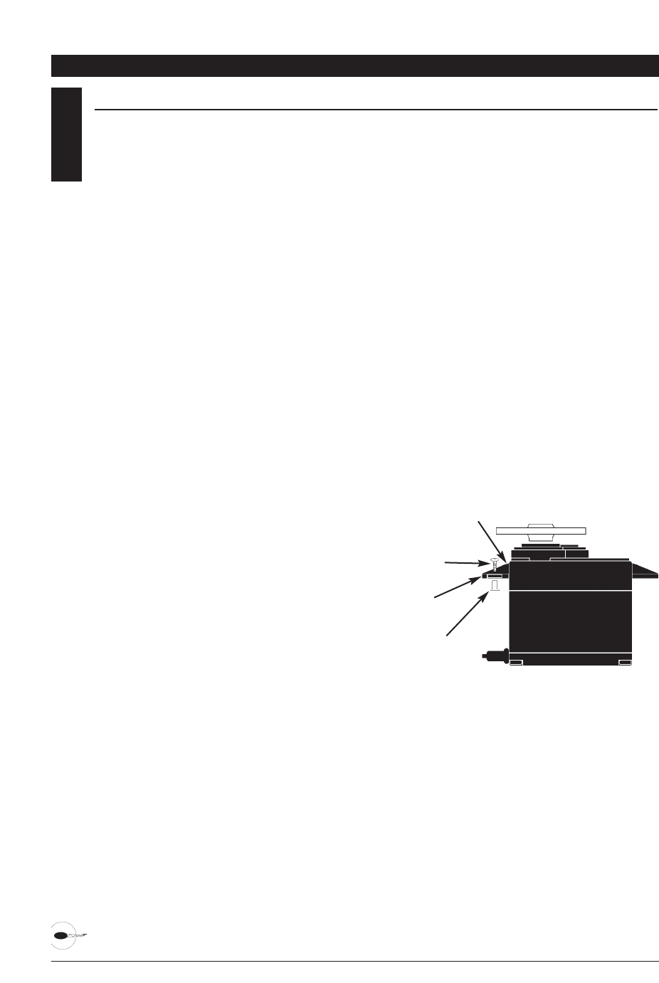
48 XP6102 - Helicopter Manual
2.1 INSTALLATION REQUIREMENTS
It is extremely important that your radio
system be correctly installed in your
model. Here are a few suggestions
installing your JR equipment:
1. Wrap the receiver in protective foam
rubber that is no less than 3/8 inch thick.
Secure the foam to the receiver with #64
rubber bands. This protects the receiver
in the event of a crash or a very hard
landing.
2. The servos should be mounted using
rubber grommets and brass eyelets to
isolate them from vibration. Do not over-
tighten the mounting screws; this will
negate the vibration absorption effect of
the rubber grommets. The following
diagram will assist you in properly
mounting your servo.
The brass eyelets are pushed from the
bottom up in the rubber grommets.
When the servo screw is tightened
securely, it provides the proper security
as well as the proper vibration isolation
for your servo.
3. The servos must be able to move freely
over their entire range of travel. Make
sure that the control linkages do not
bind or impede the movement of any of
the servos.
4. Mount all switches away from the
engine exhaust and away from any high
vibration areas. Make sure the switch
operates freely and is able to operate
over its full travel.
5. Mount the receiver antenna firmly to
the airplane to ensure that it will not
become entangled in the propeller or
control surfaces.
CHAPTER 2: CONNECTIONS • HELICOPTER
Servo Mounting Tab
Screw
Rubber Grommet
Brass Eyelet
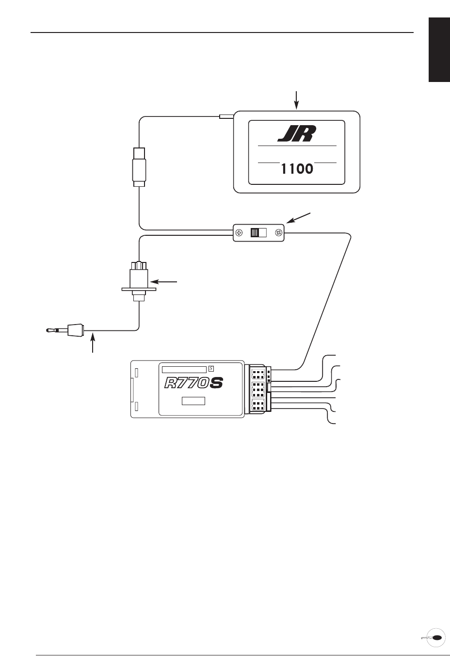
49XP6102 - Helicopter Manual
CONNECTIONS 2.2
ON
OFF
AUX2
AUX1
GEAR
RUDD
ELEV
AILE
THRO
BATT
NEW ABC&W SYSTEM
7 CHANNEL SPCM RECEIVER
JAPAN REMOTE CONTROL CO., LTD
MADE IN MALAYSIA
72 MHz
SYSTEM
EXTRA
JAPAN REMOTE CONTROL CO., LTD
MAH CE
AUXILIARY 1/PITCH
GEAR/GYRO
THROTTLE
AILERON
ELEVATOR
RUDDER
BATTERY
CHARGECORD OR
D.S.C. RECEPTACLE
(JRPS024)
CHARGECORD OR D.S.C.
D.S.C. - (JRPA132)
CHARGER - (JRPC221)
DELUXE SWITCH HARNESS
(JRPS024)
RECEIVER BATTERY 4N-1100
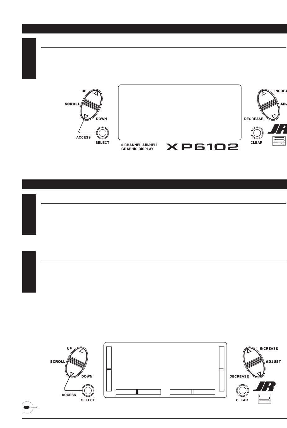
50 XP6102 - Helicopter Manual
3KEY INPUT AND DISPLAY
The Function Selection keys are used to
move up and down through the
functions.The Channel key is used to
advance the channel or function selected.
The Increase and Decrease keys are used
to make changes in the selected functions.
CHAPTER 3: INPUT MODE AND FUNCTION • HELICOPTER
4.1 BATTERY ALARM AND DISPLAY
When the transmitter voltage drops
below 9.0 volts DC, the display flashes
“BATT LOW” and an alarm sounds.
If you are flying when this occurs, land
immediately.
CHAPTER 4: ALARM AND ERROR DISPLAY • AIRPLANE
4.2 BACKUP ERROR DISPLAY
All preprogrammed data is protected by a
five-year lithium battery that guards
against main transmitter battery failure.
Should the lithium battery fail, the display
will indicate BACK ERROR. If this occurs,
it will be necessary to replace the lithium
battery and reprogram all data. All
transmitter programs will return to the
factory default settings, and the data you
have input will be lost. When it becomes
necessary to replace the lithium back-up
battery, contact JR Horizon Service
Center. Due to the possibility of extensive
damage caused by improper removal or
replacement, only JR Horizon Service
Center is authorized to make this change.
BACK ERROR
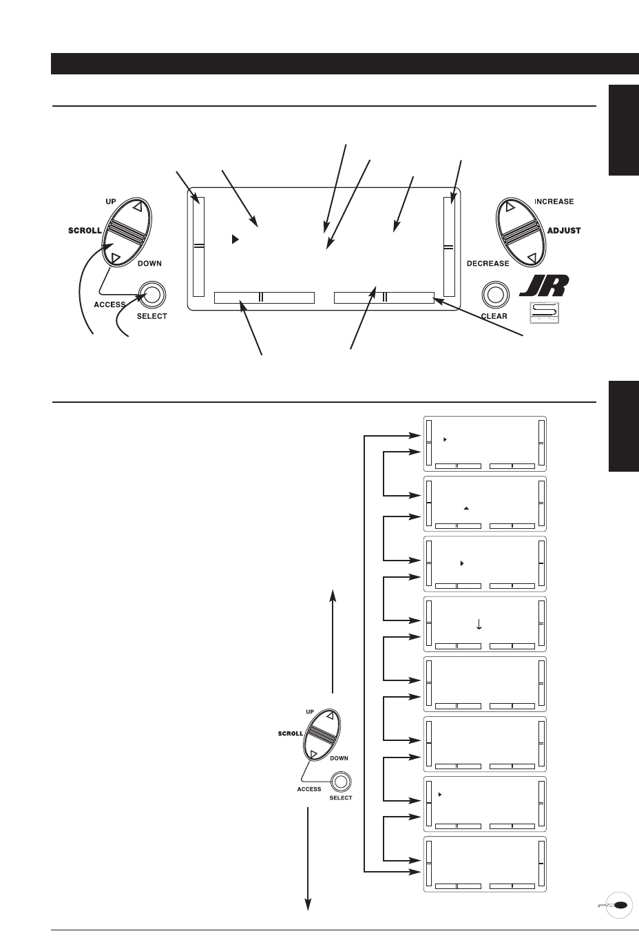
51XP6102 - Helicopter Manual
CHAPTER 5: SYSTEM MODE • HELICOPTER
NORMAL MODE 5.1
When the power switch is in the On
position, the display will read as follows:
[MODEL SEL]
#5 HELI SPCM
VENTURE
TOTAL T 0:22:42
To enter and exit the System mode, press
simultaneously then turn on the power switch.
To enter and exit the Function model, turn on
the power switch, then press simultaneously.
Elevator Trim
Aileron Trim
Rudder Trim
Throttle Trim Modulation Type
Model Type
Model Number
Transmitter
"On Time"
Model Name
SYSTEM MODE 5.2
To enter the System mode, press the
Down and Channel keys simultaneously,
then turn the power switch to the on
position. The display will show the last
active program. Pressing either the Up or
Down key then scrolls through the
functions one by one, according to the
system mode flowchart shown to the right.
Once the appropriate function is
displayed, changes can be made by
pressing the (+) or (-) keys.
System Mode Flowchart
Information pertaining to each function is
explained on the page listed next to the
function name. Functions will appear in
the same order they are shown on
this chart.
Accessing the System Mode
1. Press the Down and Channel keys
simultaneously.
2. Move the power switch to the On
(upper) position.
3. Use either the Up or Down key to
scroll through the menu and access the
applicable function.
[MODEL SEL]
#5 HELI SPCM
VENTURE
TOTAL T 0:22:42
[MODEL NAME]
#5 HELI SPCM
VENTURE
[MODEL TYPE]
#3 VENTURE
HELICOPTER
DATA RESET
[MODEL COPY]
#3 VENTURE
#2 HELI SPCM
[MODULATION]
#5 VENTURE
SPCM
[TRAINER]
#3 VENTURE
NORMAL
[SWITCH SEL]
D/R INDIVID
GEAR LEFT SW
FL-M LEFT SW
[SWASH TYPE]
NORMAL
1SERVO
Model
Selection
pg 52
Model
Name
Entry
pg 53
Model
Type
pg 54
Model
Copy
pg 55
Modu-
lation
pg 56
Trainer
pg 57
Switch
Select
pg 58
Swash
Type
pg 59
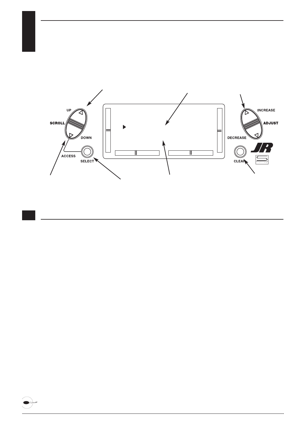
52 XP6102 - Helicopter Manual
5.3 MODEL SELECTION
The XP6102 system offers memory for ten
completely separate models. Therefore,
it is possible to have a mixture of
helicopter and airplane setups retained
in memory. It is also recommended that
the Model Name Entry function be used
in conjunction with each model setup.
Another very useful function of the Model
Selection function is the ability to set
one aircraft up several different ways.
This is helpful when multi-task
performance is desired.
[MODEL SEL]
#5 HELI SPCM
VENTURE
TOTAL T 0:22:42
Model Name (if programmed)
Model Number and Type
Toggle between Model
and Timer
Clear Timer (when selected)
Go to Model Name menu
Go to Swashplate Type menu
Change model selection
Accessing the Model Select Function
1. While pressing the Down and Select
keys, switch the transmitter to the On
position to enter the Model Select mode.
2. Model Select will be displayed on the
upper left portion of the LCD. If not,
press the Up or Down key until MODEL
SEL is displayed.
3. Pressing the (+) or (-) key will select
among each of the ten models available.
Notice that as each model is selected, its
name appears in the LCD.
4. Once the desired model is displayed on
the left, pressing the Down and Channel
keys simultaneously will exit the Model
Selection function and establish the
model displayed as the new current
model.
5. Press the Select key to select the timer
function to clear the Total Timer. Press
the Clear key to clear the Total timer.
6. Press the Down key to access the
SWASH TYPE function.
7. Press the Up key to access the MODEL
NAME function.
8. Press the Down and Select keys
simultaneously to exit the MODEL SEL
function.
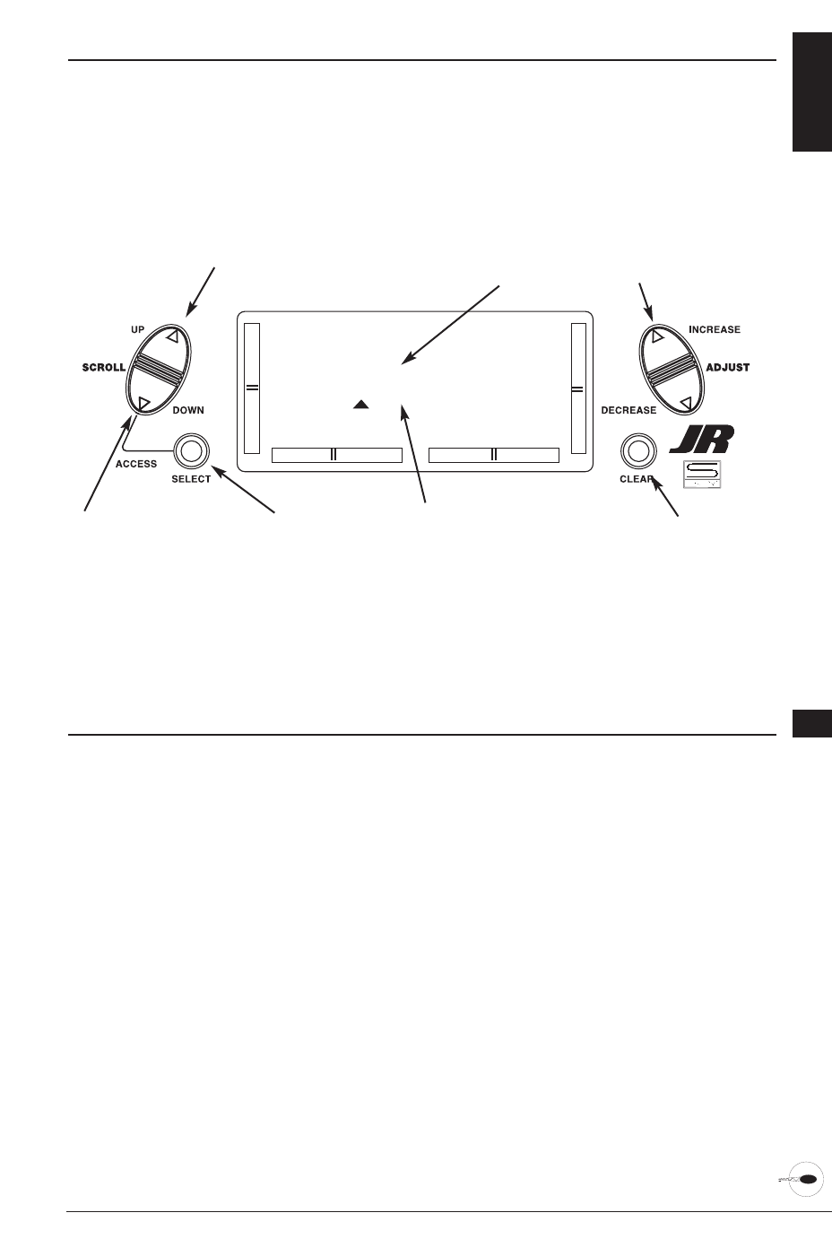
53XP6102 - Helicopter Manual
MODEL NAME ENTRY 5.4
The XP6102 allows an 8-digit name to be
input for each of the ten models available.
The current model will be displayed in the
Normal display.
Accessing the Model Name Entry Function
1. While pressing the Down and Select
keys, switch the transmitter to the On
(upper) position to enter the Model
Setup mode.
2. press the Up or Down key until
MODEL NAME is displayed.
2. Press either the Up or Down key to
select the first character for the model
name.
4. Press the Select key to advance the
character selection to the next character.
5. Repeat this procedure until all eight
characters have been selected.
6. Press the Down key to access the
MODEL SEL function.
7. Press the Up key to access the MODEL
TYPE Selection function.
8. Press the Down and Select keys
simultaneously to exit the MODEL
NAME function.
[MODEL NAME]
#5 HELI SPCM
VENTURE
Model name being
programmed
Model Number and Type
Select character Reset selected
character to blank
space
Go to Model Type menu
Go to Model Select menu
Change selected
character
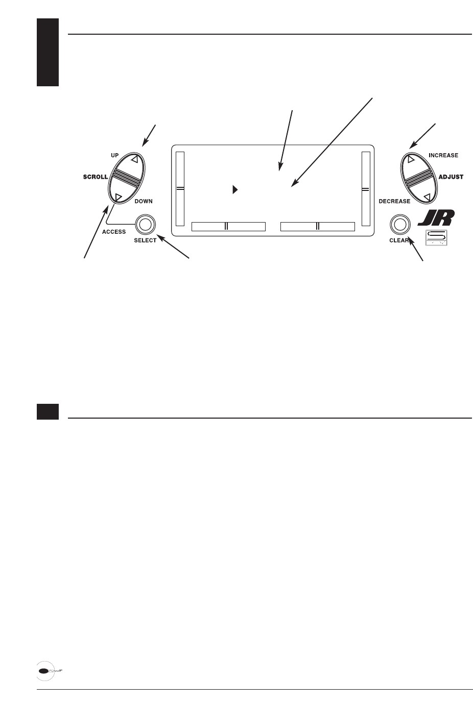
54 XP6102 - Helicopter Manual
5.5 MODEL TYPE SELECTION
The XP6102 is capable of performing
as a helicopter or airplane radio with
full functions for each.
Accessing the Type Selection Function
1. While pressing the Down and Select
keys, switch the transmitter to the On
position to enter the Model Setup mode.
2. Press either the Up or Down keys until
MODEL TYPE is displayed in the left
portion of the LCD.
3. Pressing either the (+) or (-) key will
change the type of model.
4. Press the Select key to move the cursor
to the Data Reset position.
5. Press the Clear key to reset the memory
to the factory defaults.
6. Press the Down key to access the
MODEL NAME function.
5. Press the Up key to access the MODEL
COPY function.
6. Press the Down and Select keys
simultaneously to exit the MODEL TYPE
function.
[MODEL TYPE]
#3 VENTURE
HELICOPTER
DATA RESET
Model Type function
Model Number and Name
Toggle between Model
Type and Data Reset Reset Data (when selected)
Go to Model Copy menu
Go to Model Name menu
Change model
type selection
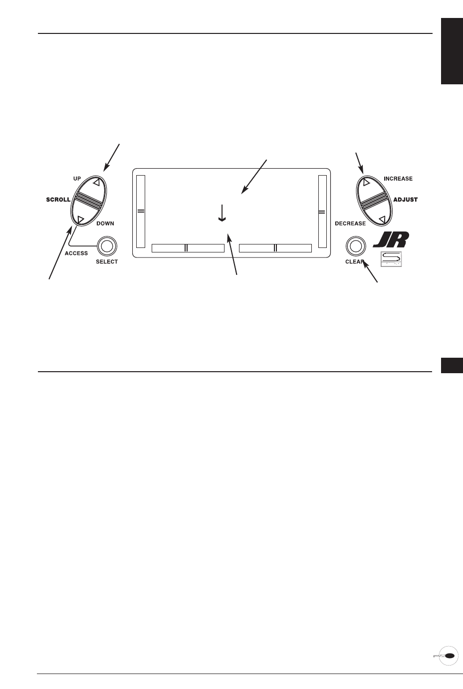
55XP6102 - Helicopter Manual
MODEL COPY FUNCTION 5.6
The Copy Selection function enables you
to copy all of the settings of the current
model to another model within the same
transmitter. This is very useful when setting
up one aircraft several different ways or
when trying an alternative setup of your
current model.
Accessing the Model Copy Function
1. While pressing the Down and Select
keys, move the transmitter’s power
switch to the On position.
2. Press either the Up or Down key until
MODEL COPY appears on the top left
of the LCD.
3. The upper number that appears is the
current model. This is important to note
as only the current model will be the
copied. Press the (+) or (-) keys to select
the desired program (lower number) to
copy the current model to.
4. Next, press the Clear key. The current
model will then be copied to the
selected model.
Note: Always make sure that the
accepting model is either free of
input or one which you no longer
want to retain in your transmitter’s
memory. Once the copying process
has been completed, the information
of the accepting model is lost and the
current model is input as the new
data.
5. Press the Up key to access the
MODULATION function.
6. Press the Down key to access the
MODEL TYPE function.
7. Press the Down and Select keys
simultaneously to exit the MODEL
COPY function.
[MODEL COPY]
#3 VENTURE
#2 HELI SPCM
Model number to
be copied to
Model number and name
to be copied
Perform copy
function
Go to Modulation menu
Go to Model Type menu
Change model to
copy to
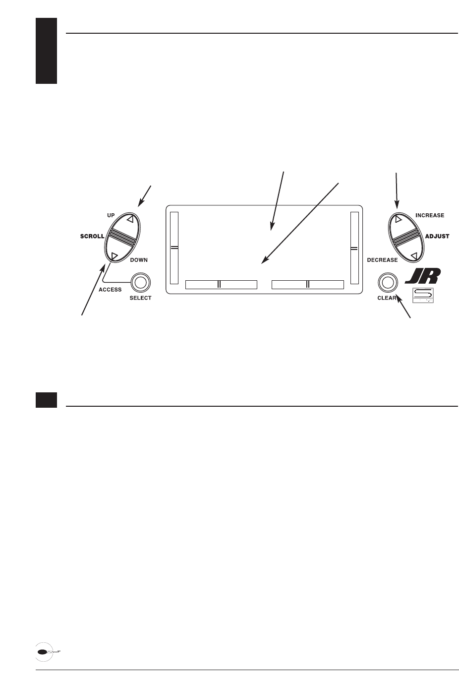
56 XP6102 - Helicopter Manual
5.7 MODULATION SELECTION
The Modulation Selection function
enables your XP6102 to transmit to a
variety of JR receivers. You can select from
either S-PCM or from linear PPM (Pulse
Position Modulation [FM]).
Accessing the Modulation Function
1. Move the power switch to the On
position while pressing the Down and
Select key to access the System mode.
2. Press either the Up or Down key until
MODULATION appears at the top of the
LCD.
3. Press either the (+) or (-) keys to change
the modulation type.
4. Pressing the Clear key will also reset
the modulation selection to the factory
preset S-PCM.
5. Press the Down key to access the
MODEL COPY function.
6. Press the Up key to access the
TRAINER function.
7. To exit the MODULATION function,
press the Down and Select keys
simultaneously.
Note: In the normal display, the selected
modulation type will appear in the
upper right of the LCD.
[MODULATION]
#5 VENTURE
SPCM
Modulation
Model Number and Name
Select S-PCM
Go to Trainer menu
Go to Model Copy menu
Toggle between
PPM and S-PCM
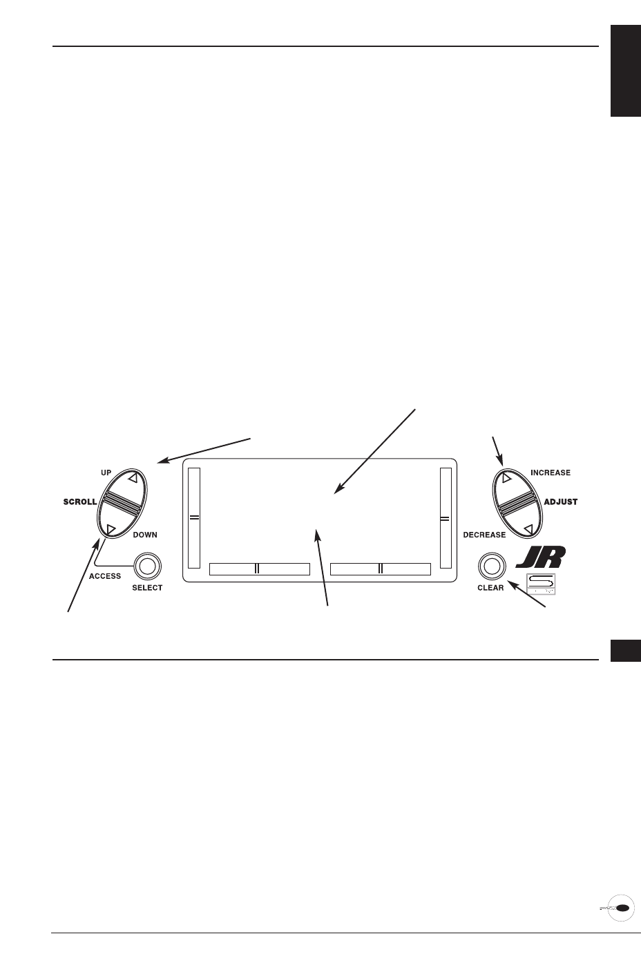
57XP6102 - Helicopter Manual
TRAINER FUNCTION 5.8
The XP6102 offers a programmable trainer
function with three trainer options:
Normal mode - In this mode the
transmitter acts as a conventional buddy-
box system. The transmitter can be used as
a slave or as a master: however in this
mode, the reversing switches and trims
must be adjusted so the slave transmitter
matches the master transmitter. In normal
mode, when the trainer switch is
activated, the student has control of all
functions and switches.
Pilot Link - When pilot link mode is used
with the master transmitter, it allows the
slave transmitter to be adjusted to factory
defaults. The slave transmitter can simply
be programmed in a model memory not
being used and reset to factory defaults,
thus preventing the need to synchronize
the trims and reversing switches on the
slave transmitter.
Also, when Pilot Link is used, the student
only has control of the 4 basic channels
(throttle, aileron, elevator, rudder) while
the trainer (master) retains control of all
other functions like gear, dual rate,
programmed mixes, etc. This allows a
pilot to have a test flight on a more
complex airplane without having to
remember complex switch positions.
Pilot Link + Slave - This mode is used
only when the XP6102 is being used as a
slave transmitter and the other Master
transmitter has a Pilot Link program
active. By selecting Pilot Link + Slave the
transmitter is automatically in the correct
programming mode to work as a slave in
conjunction with another Pilot Link
equipped transmitter.
Accessing the Trainer Function
1. Move the power switch to the On
position while pressing the Down and
Select keys to access the System mode.
2. Press either the Up or Down key until
TRAINER appears at the top of the LCD.
3. Press either the (+) or (-) keys to change
the Trainer Type type.
4. Pressing the Clear key will return the
trainer function to the "normal" setting.
5. Press the Down key to access the
MODULATION function.
6. Press the Up key to access the SWITCH
SEL function.
7. To exit the TRAINER function, press the
Down and Select keys simultaneously.
Note: The slave transmitter must always
be in PPM modulation to operate.
Pilot Link + Slave automatically selects
PPM modulation when activated.
With other transmitters it will be
necessary to be in PPM mode for the
XP6102 to operate properly as a slave.
[TRAINER]
#3 VENTURE
NORMAL
Trainer mode selected
Model number and name
Return to Normal mode
Go to Switch Select menu
Go to Modulation menu
Change trainer
mode
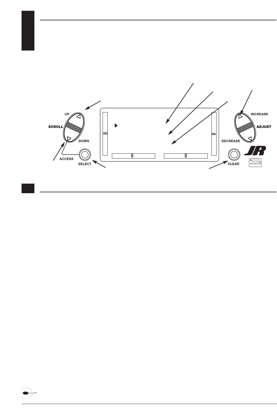
58 XP6102 - Helicopter Manual
5.9 SWITCH SELECT
The XP6102 allows the several options to
be programmed for the dual rate, gear and
flap switches.
Aileron and elevator dual rates can be
programmed to be individually selected
via it's own switch (Individ) or the aileron,
elevator and rudder functions can be
combined to operate from one of 4
switches.
The gear channel can be programmed to
operate on one of 4 switched or rockers
or it can be inhibited, helpful for some
types of mixing. Plus the flap channel can
be programmed to operate from switches
or levers.
[SWITCH SEL]
D/R INDIVID
GEAR LEFT SW
FL-M LEFT SW
Gear indicator
Dual Rate indicator
Reset selection to default
Go to Swashplate Type menu
Go to
Trainer menu
Switch selection
Accessing the Modulation Function
Dual Rates
D/R INDIVID (default) - In this mode
the aileron and elevator rates are
independently selected using the
ELEV D/R and AILE D/R switches.
Note: In this mode the rudder D/R is
always in the 0 position and is not
selectable. This is the default setting.
COM AILE - In this mode the aileron,
elevator and rudder dual rates are
combined on the AILE D/R switch.
COM ELEV - In this mode the aileron,
elevator and rudder dual rates are
combined on the ELEV D/R switch.
COM R-SW - In this mode the aileron,
elevator and rudder dual rates are
combined on the upper right (flap) switch.
COM L-SW - In this mode the aileron,
elevator and rudder dual rates are
combined on the upper left (gear) switch.
Gear Channel
LEFT SW (default) - The gear channel
operates from the left upper (gear) switch.
AILE D/R - The gear channel operates
from the aileron dual rate switch.
ELEV D/R - The gear channel operates
from the elevator dual rate switch.
INHIBIT - The gear channel is inhibited
and is centered making it useful as a slave
channel for mixing.
RIGHT SW - The gear channel operates
from the right upper (flap) switch.
Flight Mode
LEFT SW - The flight mode operates from
the left upper (gear) switch.
AILE D/R - The flight mode operates from
the aileron dual rate switch.
ELEV D/R - The flight mode operates from
the elevator dual rate switch.
RIGHT SW (default) - The flight mode
channel operates from the right
upper switch.
Flight mode indicator
Select function
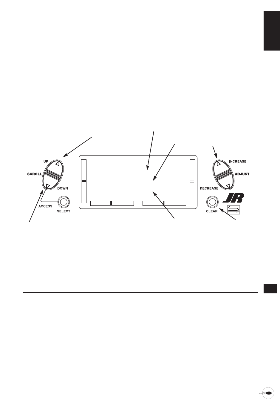
59XP6102 - Helicopter Manual
SWASHPLATE TYPE SELECTION 5.10
The Swashplate Mixing function enables
the XP6102 system to operate many
different types of swashplate control
systems, including 3 versions of CCPM.
The Swashplate options are:
1 Servo: Non-CCPM, standard mixing
type helicopter.
2 Servo/180° CCPM
3 Servo/120° CCPM (JR style, most
popular)
3 Servo/90° CCPM
[SWASH TYPE]
NORMAL
1SERVO
V-Tail indicator
Flaperon indicator
Return to Default mode
Go to Model Select menu
Go to Switch Select menu
Turn selected
type on or off
Elevon indicator
Definition of Swashplate Types
1. While pressing the Down and Select
keys, switch the transmitter to the ON
position to enter the system mode.
2. Press either the Up or Down key until
SWASH TYPE is displayed in the upper
center portion of the LCD.
3. Press the (+) or (-) keys to change the
Swashplate type.
4. Pressing the Clear key will reset the
Swashplate Type to the Normal
position.7. To access the AUX2 Switch
function, press the Down key.
5. Press the Up key to access the MODEL
SELECT function.
6. Press the Down key to access the
SWITCH SELECT function.
7. Exit the SWASH TYPE function by
pressing the Down and Select keys
simultaneously.

60 XP6102 - Helicopter Manual
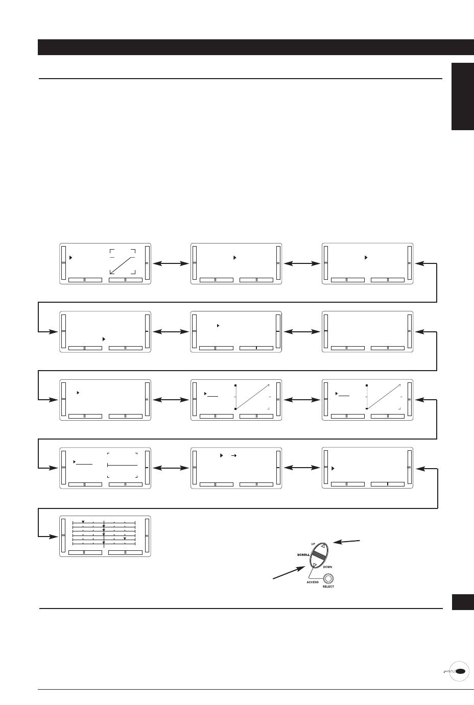
61XP6102 - Helicopter Manual
CHAPTER 6: FUNCTIONS (FUNCTION MODE ) • HELICOPTER
FUNCTION MODE 6.1
To enter the Function mode, switch the
transmitter power switch to the On
position. Press the Down and Select keys
simultaneously, and the display will
show the last active program. Pressing
either the Up or Down key then scrolls
through the functions one by one,
according to the Function Mode
Flowchart shown on the right. Once the
appropriate function is displayed, changes
can be made by pressing the (+) or (-)
Accessing the Mode Function
1. Move the power switch to the On
position.
2. Press the Down and Select keys
simultaneously.
[D/R & EXP]
AILE POS 0
EXP LIN
D/R 100%
Dual Rate and Expo pg 62
[TRAVEL ADJ]
THRO AILE
H100% L100%
L100% R100%
Travel Adjustment pg 65
[THROTTLE HOLD]
POS O OFF
SW RIGHT
Throttle Hold pg 69
[REVO MX]
NORMAL
UP 0%
DN 0%
Revo MX pg 75
[REVERSING SW]
THR:N AIL:N
ELE:N RUD:N
GEA:N FLA:N
Reversing Switches pg 63
[120o CCPM] REV
AILE 60% N
ELEV 60% N
PIT 60% N
CCPM Swashplate Mixing pg 66
[THRO]
NORM
I 1
O 1
Throttle Curve pg 70
[MX1] THR THR
ON OFFSET 0
0% 0%
SW ALWAYS ON
Programmable Mix 1&2 pg 77
[SUB TRIM]
TH 0 AI 0
EL 0 RU 0
GE 0 FL 0
Sub Trim pg 64
[THRO CUT]
INHIBIT
Throttle Cut pg 68
[PITCH]
NORM
I 1
O 1
Pitch Curve pg 73
3. Use either the Up or Down to scroll
through the menu and access the
applicable function.
keys. To select another channel of a
particular function, press the Select key.
The Function mode is the most often used
system to input data.
Function Mode Flowchart
Information pertaining to each function is
explained on the page listed next to the
function name. Functions will appear in
the same order they are shown on this
chart.
Navigate forward
through menus
Navigate backwards
through menus
[FAIL SAFE]
TH HLD AI HLD
EL HLD RU HLD
GE HLD FL HLD
Fail Safe pg 80
1
3
5
2
4
6
Servo Travel Screen pg 81
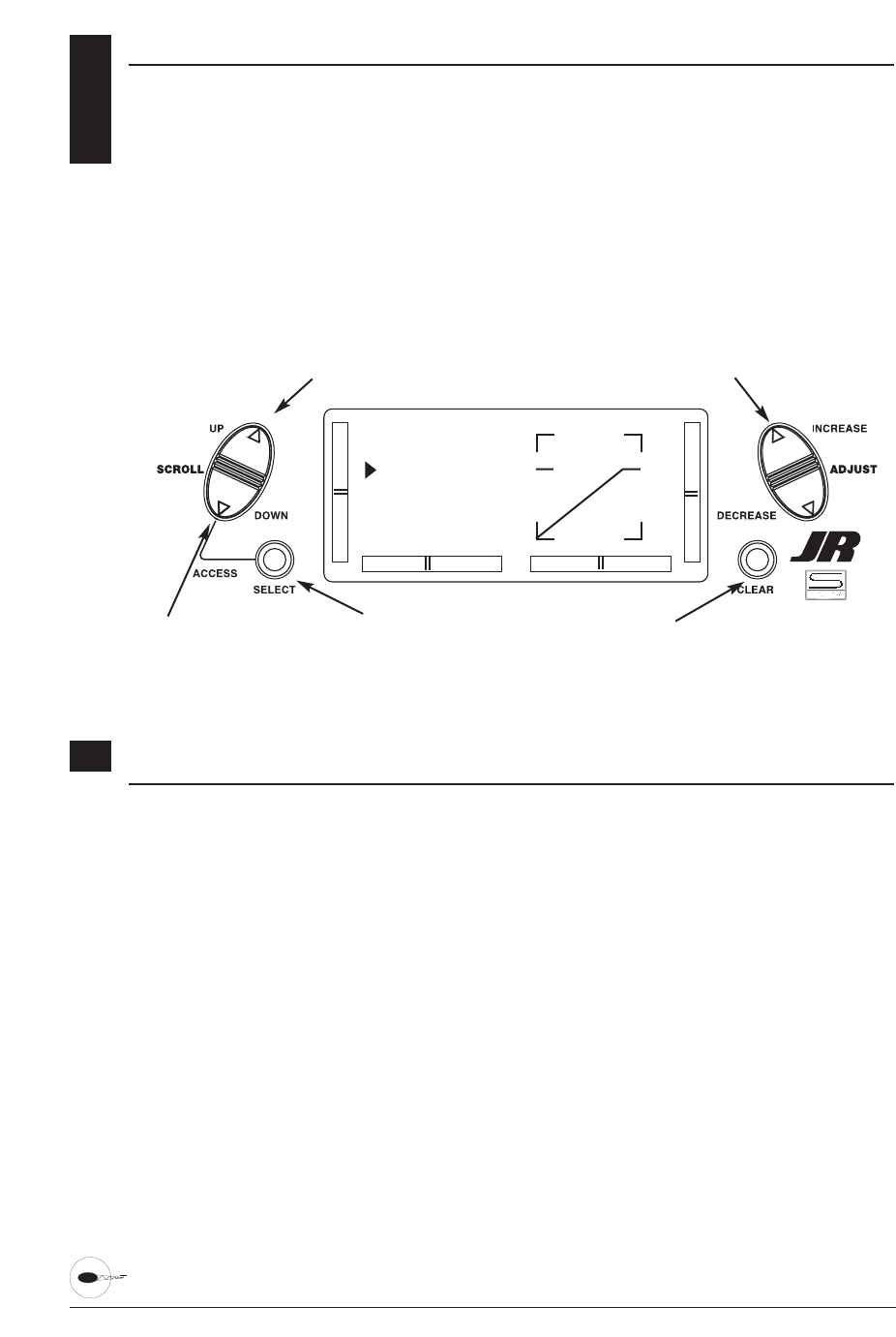
6.2 DUAL RATES AND EXPONENTIAL
Dual rates are available for the aileron,
elevator and rudder channels of your R/C
aircraft. There is also an automatic dual
rate setting to link your aileron, elevator,
and rudder dual rates to the flight model
switch. This automatic Dual-Rate function
is discussed in a separate section that
follows. Dual rates may be defined as the
ability to vary the travel or throw rate of a
servo from a switch. Due to the differing
travel rates, you will find that the
sensitivity of the control either increases
or decreases accordingly. A higher rate, or
travel, yields a higher overall sensitivity.
You may find it easier to think
of the Dual-Rate function as double-rates
or half-rates.The Dual-Rate function works
in conjunction with the Exponential
function to allow you to precisely tailor
your control throws. You may want to
consult the section defining exponential
for further information.
62 XP6102 - Helicopter Manual
Accessing the Dual Rate and Exponential Function
1. Place the transmitter power switch in
the on position.
2. Access the Function mode by pressing
the Down and Select keys
simultaneously.
3. Press either the Up or Down key until
D/R & EXP appears in the upper left
corner of the LCD.
4. Press the Channel key until the desired
channel (aileron, elevator, rudder or
automatic dual rates) appears.
5. Select the switch position for which you
want to adjust the rate. The number to
the upper right of the current rate value
on the display indicates the current
position of the Dual-Rate switch for the
channel that you have selected. Either a
0 or a 1 will be shown, corresponding to
the position of the switch. To select the
opposite switch position, move the
appropriate Dual-Rate switch to the
opposite position. The number that
appears above the current rate value
reflects the change.
6. Adjust the rate for the channel and the
switch position that you have just
selected. To decrease the throw rate,
press the (-) key. To increase the throw
rate, press the (+) key. As stated
previously, the adjustable rate is from 0-
125% for each switch position and
channel.
7. Press the Up arrow key to access the
REVERSING SW menu.
8. Press the Down arrow key to access the
SERVO TRAVEL SCREEN.
9. Press the Down arrow and Select keys
simultaneously to exit the function
mode.
The amount of travel is adjustable from
0-125% in 1% increments. The factory
setting, or default value, for both the
0 and 1 switch positions is 100%.
Either switch position may be selected as
the low or high rate by placing the switch
in the desired position and adjusting
the value accordingly.
[D/R & EXP]
AILE POS 0
EXP LIN
D/R 100%
Go to Reversing SW menu
Go to Servo Travel Screen Select channel, EXP or D/R
Change channel or value
Reset selection to default
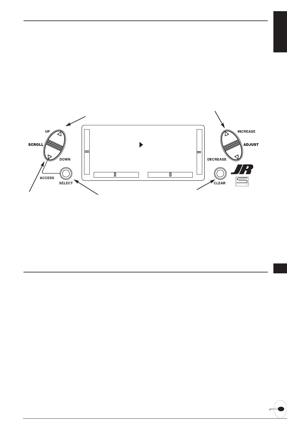
SERVO REVERSING 6.3
The Reverse Switch function is an
electronic means of reversing the throw
of a given channel (servo). All six channels
of the XP6102 offer reversible servo
direction. This will ease setup during
the servo installation into your aircraft.
63XP6102 - Helicopter Manual
Accessing the Servo Reversing Function
1. Place the transmitter switch in the on
position.
2. Access the Function mode by pressing
the Down and Select keys
simultaneously.
3. Press either the Up or Down key until
the REVERSING SW appears in the
upper portion of the LCD.
4. Using your transmitter’s control sticks,
switches and potentiometers, move the
control surfaces of your aircraft. Note
the travel direction of each of the
corresponding control surfaces.
5. After determining which channel(s)
need to have the throw directions
reversed, use the Select key to call up
the appropriate channel.
6. Press either the (+) or (-) keys to change
the travel direction of the servo. Pressing
the Clear key returns the travel direction
to Normal.
7. You can observe the change in the
travel direction by moving the
appropriate control at this time.
8. Access the D/R & EXP function by
pressing the Down key.
9. Access the SUB TRIM function by
pressing the Up key.
10. Exit the Servo Reversing function by
pressing the Down and Select keys
simultaneously.
[REVERSING SW]
THR:N AIL:N
ELE:N RUD:N
GEA:N FLA:N
Go to Sub Trim menu
Go to D/R & Exp menu
Change servo direction
Reset direction to normal
Select channel to reverse
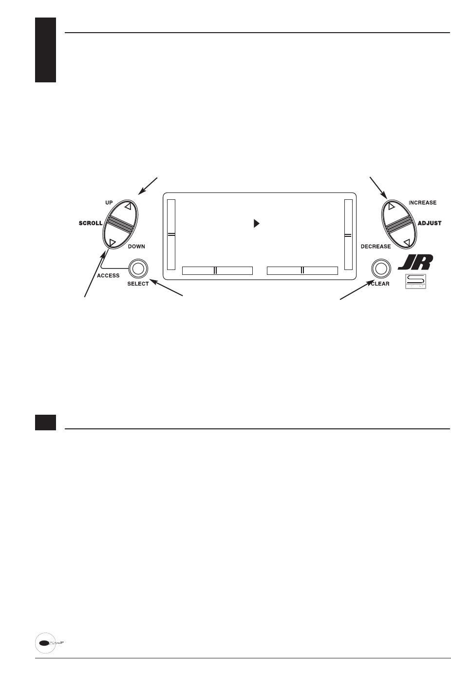
6.4 SUB TRIM
The Sub Trim Adjustment function allows
you to electronically fine-tune the
centering of your servos. Individually
adjustable for all six channels with a
range of ±125% (+/-30 degrees servo
travel).
The sub trim functions provides precise
servo arm neutral positioning if rotating
the servo arm will not allow the desired
servo arm position.
64 XP6102 - Helicopter Manual
Accessing the Sub Trim Function
1. Place the transmitter power switch in
the On position.
2. To Access the Function mode, press the
Down and Select keys simultaneously.
3. Press either the Up or Down key until
SUB TRIM appears in the upper middle
portion of the LCD.
4. Press the Select key until the desired
channel appears.
5. Press the (+) or (-) key to establish the
desired amount and direction of Sub-
Trim.
Caution: Do not use excessive sub-trim
adjustments since it is possible to
overrun your servo’s maximum Sub
Trim. Remember that it is a trim
convenience function. It is not
intended to take the place of the
proper mechanical trim adjustments
that are necessary on any R/C model.
6. Access the REVERSING SW function by
pressing the Down key.
7. Access the TRAVEL ADJ function by
pressing the Up key.
8. Exit the SUB TRIM function by pressing
the Down and Select keys
simultaneously.
[SUB TRIM]
TH 0 AI 0
EL 0 RU 0
GE 0 FL 0
Go to Travel Adj menu
Go to Reversing SW menu Select channel
Change value
Reset selection to default

TRAVEL ADJUST 6.5
The purpose of Travel Adjust is to offer
you precise servo control deflection in
either direction of servo operation. The
XP6102 offers travel adjust for all six
channels. The Travel Adjust range is from
0-150% (0 degrees to 60 degrees) from
neutral, or center, and it can be adjusted
for each direction individually. The factory
default (Data Reset) value is 100% for
each direction of servo travel.
65XP6102 - Helicopter Manual
Accessing the Travel Adjust Function
1. Place the transmitter power switch in
the On position.
2. Access the Function mode by pressing
the Down and Select keys
simultaneously.
3. Press either the Up or Down key until
TRAVEL ADJ appears in the upper
portion of the LCD.
4. Press the Select key until the desired
channel is highlighted.
5. Move the appropriate control stick
(lever, switch, etc) to the right or left of
center to the direction of travel you want
to adjust. An arrow to the left of the
travel adjust value will reflect the current
position to be adjusted.
6. After the control stick or switch is
placed in the direction of travel to be
adjusted, press the (+) or (-) key until the
proper amount of servo travel is shown
on the LCD. Press the (+) key to increase
the amount of servo travel. Press the (-)
key to decrease the amount of servo
travel.
7. Follow the same procedure for the
remaining channels.
8. Access the SUB TRIM function by
pressing the Down key.
9. Access the THROTTLE CUT function by
pressing the Up key.
10. Exit the TRAVEL ADJ function by
pressing the Down and Select keys
simultaneously.
[TRAVEL ADJ]
THRO AILE
H100% L100%
L100% R100%
Go to Throttle cut menu
Go to Sub Trim menu
Change value
Reset value to normal
Select channel to adjust
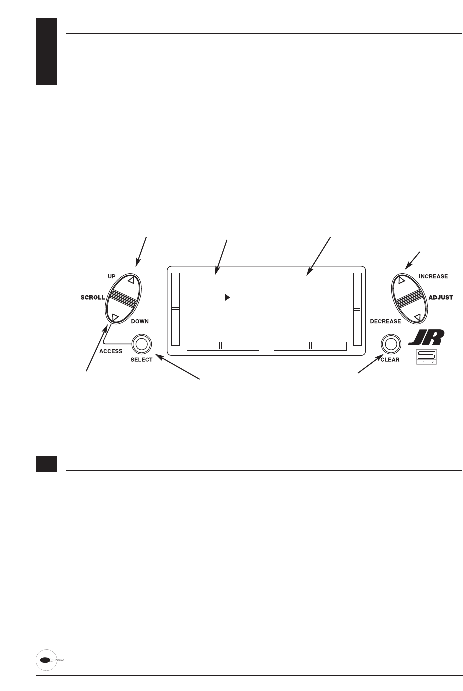
6.6 CCPM SWASHPLATE MIXING
Note: The CCPM Swashplate Mixing
screen is only displayed when
Swashplate types 2Serv, 3Serv or
4Serv CCPM are selected in the
Swashplate type Selection in System
Mode.
The CCPM Swashplate Mixing
Function(Cyclic Collective Pitch Mixing)
of the XP6102 is designed to be used in
model helicopters that utilize 2-
servo(180°), 3-servo(120°) and 3-
servo(90°) type swashplate control system.
The desired swashplate mixing type must
first be selected at the Swash Type
Selection in System Mode.
If The Swashplate Type option has not
been selected, proceed to Throttle Cut
section.
66 XP6102 - Helicopter Manual
Accessing the Swashplate Type
1. Place the transmitter power switch in
the ON position.
2. Access the Function Mode by pressing
the Down and Select keys
simultaneously.
3. Press either the Up or Down key until
90° CCPM, 120° CCPM or 180° CCPM
appears in the middle left
portion of the LCD.
Note: The swash plate type selection
is selected in the System mode on
Page. 58.
4. Press the Select key until the desired
function is highlighted.
5. Press the (+) or (-) Keys to Increase or
Decrease the CCPM Values.
6. Follow the same procedure for the
remaining channels.
8. Access the TRAVEL ADJ function by
pressing the Down key.
9. Access the THROTTLE CUT function by
pressing the Up key.
10. Exit the CCPM SETUP screen by
pressing the Down and Select keys
simultaneously.
[120o CCPM] REV
AILE 60% N
ELEV 60% N
PIT 60% N
Go to the Throttle Cut menu
Go to the Travel Adjustment menu
Indicates the CCPM type selected Indicates servo reversing
Change highlighted function Return highlighted value to default
Increase/decrease value
or
change reversing value
Screen showing 120° CCPM Swashplate selection

67XP6102 - Helicopter Manual
CCPM Swashplate Mixing (continued)
CCPM is a type of pitch mixing where the
two or three servos are connected directly
to the swashplate of the helicopter and
physically move both together and
independently for all changes in
pitch/cyclic. Please refer to the diagram
below.
1). One servo (Standard Mechanical
Mixing)
The most common form of Swashplate
Mixing. This type uses each of the three
servo to move the swashplate individually
for pitch, Aileron, and Elevator changes. If
one servo (NORM) is selected in the
System Mode (Factory Default), the
Swashplate Type Function will not appear
on the LCD screen in this section.
2). Two servo (180-degrees)
Two servos are used to move the
swashplate, and are spaced at 180degrees
apart. This is not a very common control
system configuration.
3). Three servo (120-degrees)
Three servos are used to move the
swashplate, and are spaced at 120degrees
apart. This is the most common form of
CCPM, and is found in JR and other
brands of Helicopters.
4). Three servo (90-degrees)
Three servos are used to move the
swashplate, and are spaced at 90degrees
apart. This is also not a very common
control system configuration.
CCPM Servo Connection/
Channel Numbers
2 servo (180°)
Ch2 = Aileron
Ch2 = Elevator
Ch6 = Pitch
3 servo (120°)
Ch2 = Aileron
Ch3 = Elevator
Ch6 = Pitch
3 servo (90°)
Ch2 = Aileron
Ch6 = Pitch
2 Servo/ 180° CCPM 3 Servo/120° CCPM
(JR style, most popular) 3 Servo/90° CCPM
Ch6Ch2
Ch3
Ch2 Ch6
Ch3
Ch2 Ch6
CCPM Servo Variations
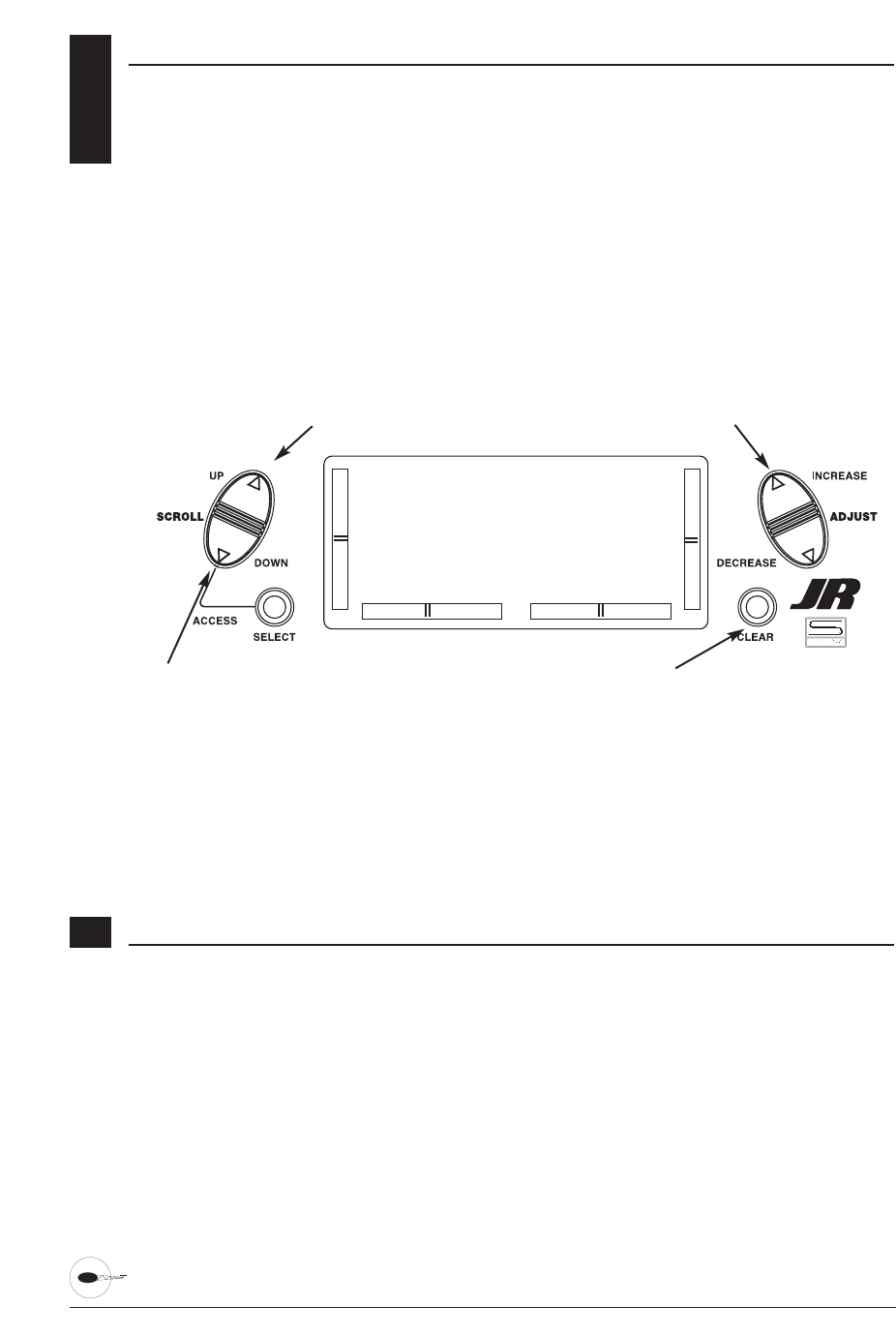
68 XP6102 - Helicopter Manual
6.7 THROTTLE CUT SWITCH
This is the function to assign Throttle Cut
switch to the push button located on
upper right front of the transmitter. The
Throttle Cut function is designed to return
the throttle trim to the lowest position
instantly and keep this position while the
button is pressed. This feature is used to
“cut” or stop the engine without changing
the position of digital throttle trim.
Accessing the Throttle Cut Function
1. Place the transmitter power switch in
the On position.
2. Access the Function mode. To do so,
press the Down and Select keys
simultaneously. Press either the Up or
Down key until THRO CUT appears in
the upper portion of the LCD screen.
3. Use the (+) and (-) keys to change the
value of the Throttle cut function.
Note: Pressing the Clear key will Inhibit
the Throttle Cut, turning it off until it
has been reactivated.
4. Access the TRAVEL ADJ mixing
function by pressing the Down key.
5. Access the THROTTLE HOLD function
by pressing the Up key.
6. Exit the THRO CUT function by
pressing the Down and Select keys
simultaneously.
[THRO CUT]
INHIBIT
Go to Travel Adjust menu
Go to throttle Hold menu Change value
Set function to Inhibit
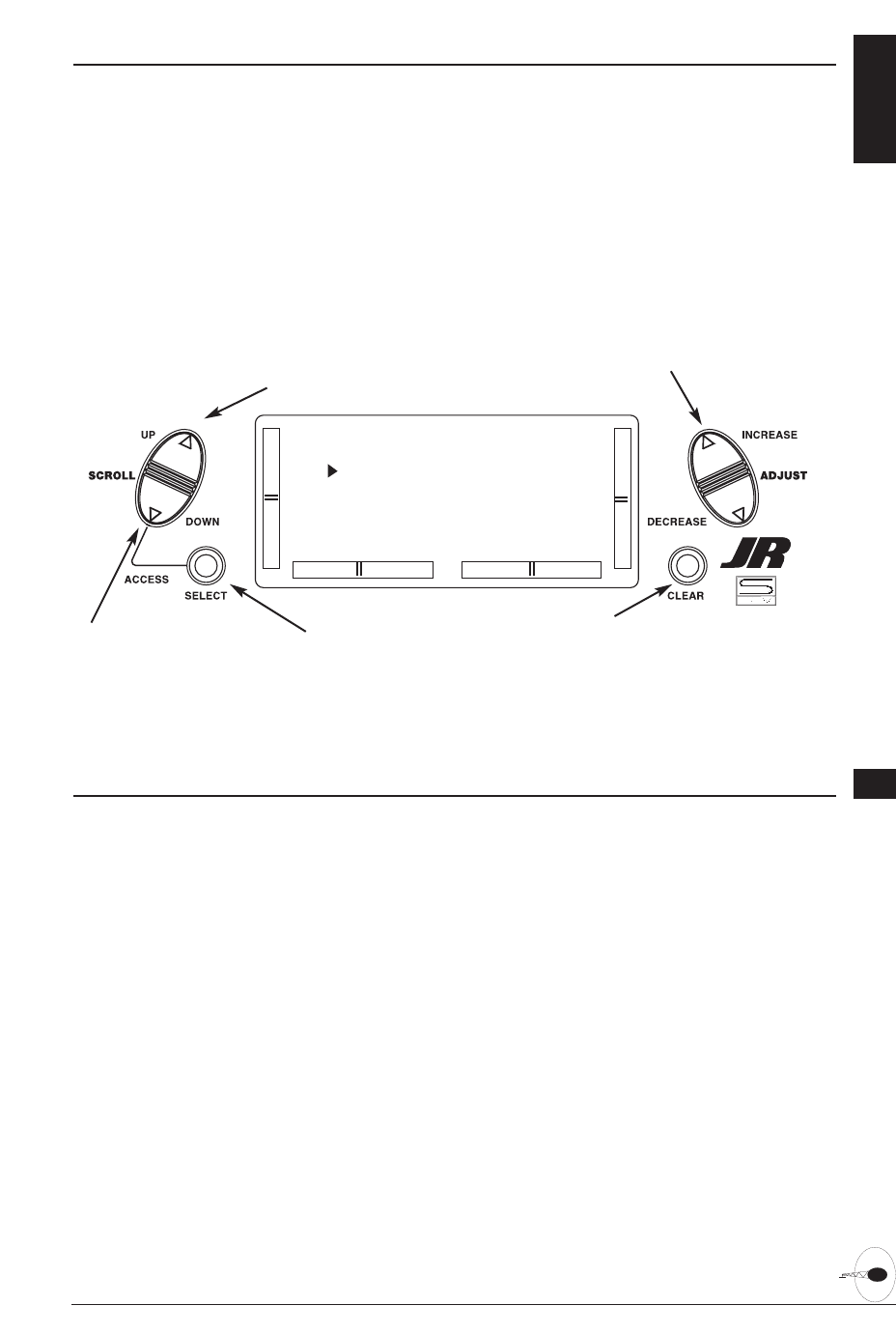
THROTTLE HOLD 6.8
The Throttle Hold function is designed to
hold the throttle servo in a specific
position during an autorotation. This is
very useful for practicing autorotation
landings. The throttle hold switch can be
programmed to one of the four toggle
switches. Throttle hold will always be
"On" in the forward switch position and
"Off" in the rear position.
69XP6102 - Helicopter Manual
Accessing the Throttle Hold Function
1. Place the transmitter switch in the On
position.
2. Press the Down and Select keys
simultaneously to enter the Function
mode.
3. Press either the Up or Down key until
THROTTLE HOLD appears across the
top of the LCD.
4. The factory setting for the throttle hold
is inhibit. Pressing either the (+) or (-)
key will activate Throttle Hold and
display the current throttle hold value.
5. Using the (+) or (-) key, adjust the
throttle hold value to deliver the proper
engine idle rpm for your helicopter. The
adjustable range is (-20%-+50%). Once
you establish the proper idle value for
your engine, you can use this value for
throttle hold as well. To shut the engine
off for autorotation, a negative or zero
value should be input.
Note: When the throttle hold is
activated, and the switch is on, the
indicator on the LCD will change
from Off to On. In addition, the
throttle trim indicator will be
inhibited.
6. Access the THROTTLE CURVE function
by pressing the Up key.
7. Access the THROTTLE CUT function by
pressing the Down key.
8. To exit the THROTTLE HOLD function,
press the Down and Select keys
simultaneously.
[THROTTLE HOLD]
POS O OFF
SW RIGHT
Go to Throttle Curve menu
Go to Throttle Cut menu
Change value/Switch selection
Reset POS value to O
or
Inhibit function
Select function to change

6.9 THROTTLE CURVES
The XP6102 offers two (2) separate throttle
curves with five adjustable points per
curve. This function allows you to
customize the throttle curve and pitch
curve together to maximize engine
performance at a particular pitch setting.
Once the throttle curves are established,
each can be activated in flight using the
two (2) position flight mode switch.
The flight mode switch offers two
selectable ranges: Normal and Stunt. The
Normal position should be used as the
hover throttle curve. The Stunt position
should be used for aerobatic maneuvers
and forward flight.
Note: The throttle trim and hovering
throttle levers are only operable when
the flight mode switch is in the
normal position. Thus, in normal
function it will have no effect. Also,
adjusting the hovering throttle lever
and throttle trim has no effect on the
input values of the throttle curve.
Each of the five points of the throttle curve
are independently adjustable from 0-
100%. These five points correspond to the
position of the throttle stick. The
illustration below shows the normal
throttle curve setting for the dead slow
position with throttle trim at default.
70 XP6102 - Helicopter Manual
The throttle trim lever position will affect
the low-point position as shown when in
the Normal mode Throttle Curve.
[THRO]
NORM
I 1
O 1
Go to Throttle Cut menu
Go to Pitch Curve menu
Change value/Switch selection
Reset value to 0
or
Set function to Inhibit
Press to access the P-LOW,
P-1, P-MID, P-3 and P-HIGH
curve points.
Stick Position
Servo position after
curve is applied Note: This screen is available
when not entering curve values
Throttle Stick
Throttle Trim
Operating Range
Hovering Throttle
Operating Range
Output Value
100%
50%
0%
P-LOW P-1 P-MID P-3 P-HIGH
The transmitter is factory preset to the
throttle curve as indicated by the solid
line in the figure at right. Individual
middle points can be increased or
decreased to suit your specific needs.
Throttle curve graph
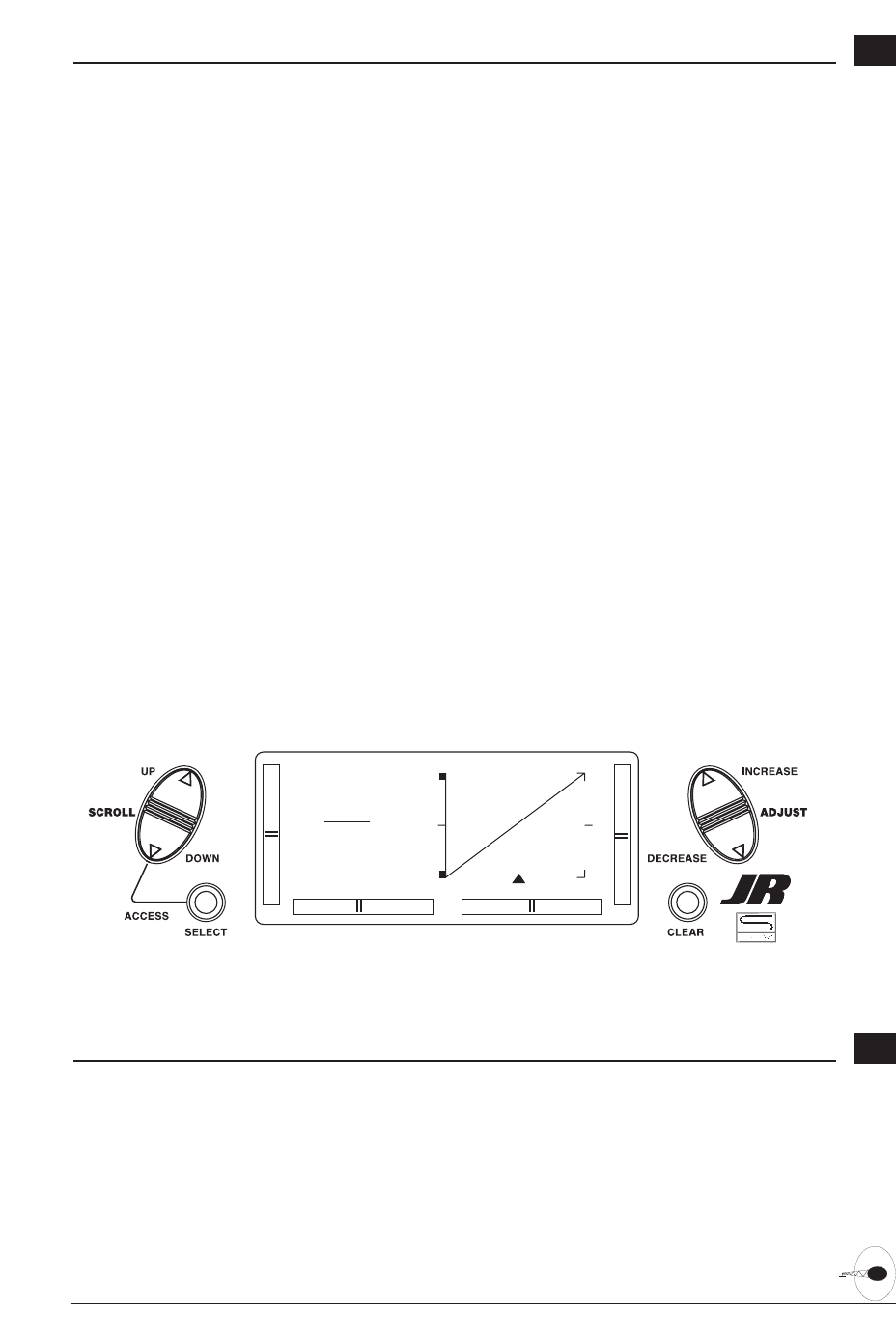
71XP6102 - Helicopter Manual
Accessing the Throttle Curve Function
1. Place the transmitter switch in the On
position.
2. Press the Down and Select keys
simultaneously to enter the Function
Mode.
3. Press either the Up or Down key until
THRO appears in the upper portion of
the LCD.
Note: Use NORM for hover curves and
STUNT for aerobatics. We will
concentrate on the hovering curve
during this example.
4. Press the Select key to select the point
of the curve you want to change.
5. Press either the (+) or (-) key to change
the value of the current curve point. The
range of each point is 0-100% in .5%
intervals.
Note: In each curve, the factory setting
indicates INH for points 1 and 3.
These values are 25% and 75%
respectively if no value changes are
made to any other points. If any of
the other points have been changed
while these points were inhibited, the
inhibited points will also change to
plot a smooth curve. If you want to
keep this from happening, press the
Select key until the display indicates
P-1 or P-3 at the upper right portion
of the LCD. Press either the (+) or (-)
key to activate the points 1 (25%) or
3 (75%). The values for each of these
curves can then be fully adjusted by
pressing either the (+) or (-) key.
6. To set curves for STUNT mode, press
the Select to highlight the NORM
function, then press the (+) or (-) key to
select the STUNT function. Repeat Steps
4 and 5 to complete the procedure.
7. Access the PITCH CURVE function by
pressing the Up key.
8. Access the THROTTLE HOLD function
by pressing the Down key.
9. Exit the THROTTLE CURVE function by
pressing the Down and Select keys
simultaneously.
Throttle Time Settings
The throttle trim lever is only active when
the flight mode switch is in the normal
position. The throttle trim is used to
increase or decrease the engine power
when the flight mode switch is in the
Normal mode. The throttle trim lever has
no effect on positions 1 or throttle hold.
Note: Making changes to the throttle
trim lever does not change the input
values for any of the points on the
throttle curve; it merely makes
adjustments to the engine idle
speed position.
[THRO]
NORM
P-3
INH
Screen showing setting the Mid-Point of the Normal Throttle Curve
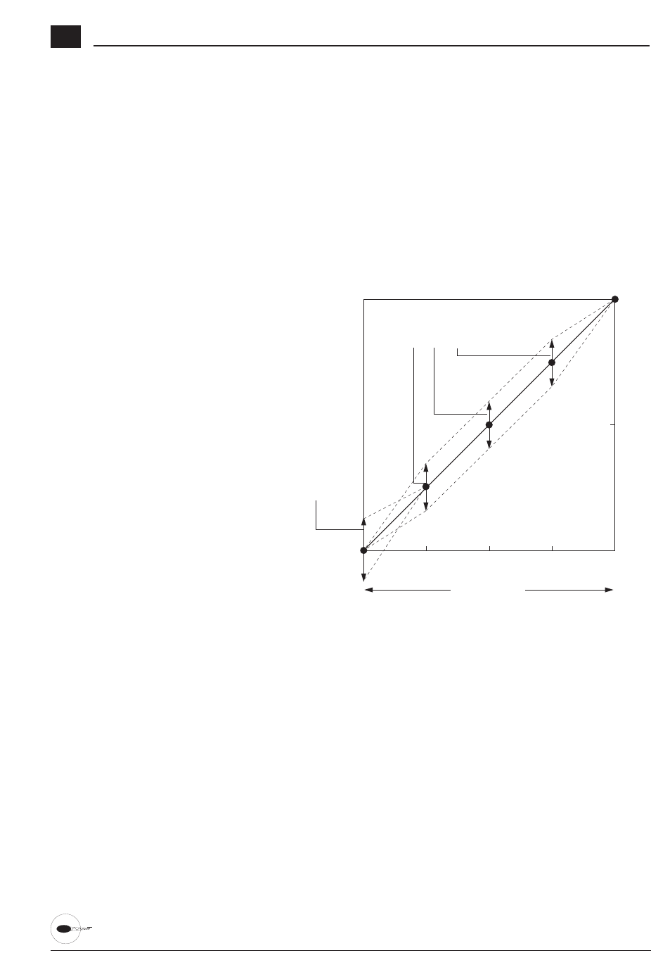
72 XP6102 - Helicopter Manual
Hovering Throttle Lever Settings
The Hovering Throttle lever increases or
decreases the engine output power for the
middle three points set for the throttle
curve. As shown in the figure below, use
of the hovering throttle lever shifts the
curve upward or downward parallel with
Throttle Stick
Throttle Trim
Operating Range
Hovering Throttle Knob
Operating Range (Parallel)
Output Value
100%
50%
0%
P-LOW P-1 P-MID P-3 P-HIGH
The throttle trim range will affect the
throttle curve as shown.
The adjustable range of output using the
hovering throttle lever is approximately
+/-9%.
Note: The Hovering Throttle has no
effect on flight mode switch
position 1.
the original curve. Therefore, operation of
the hovering throttle knob does not cause
any change to the original settings of the
throttle curve.
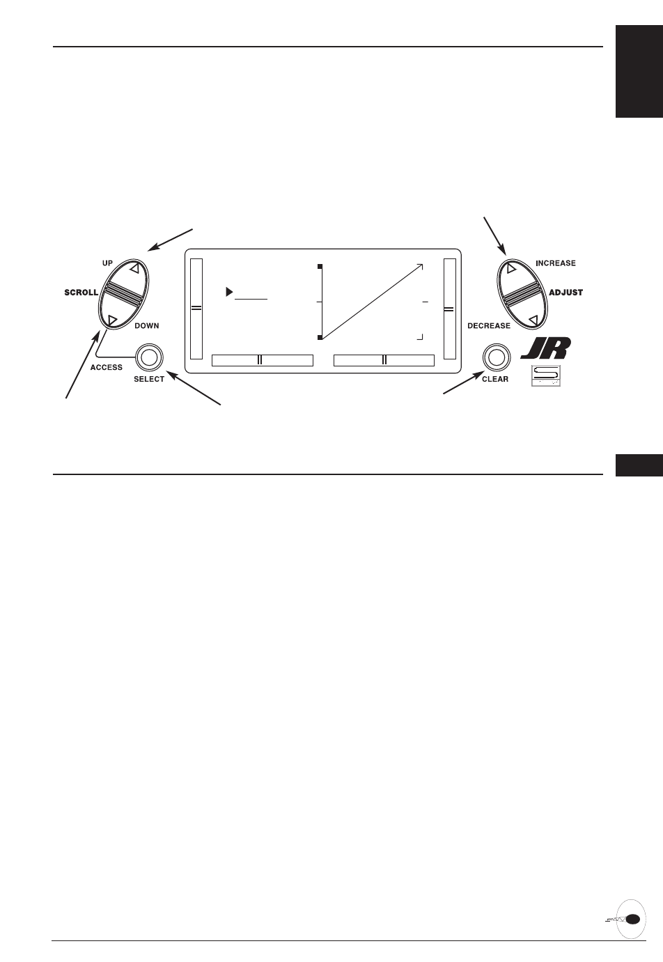
PITCH CURVES 6.10
Adjustment of the pitch curve is very
similar to the throttle curve adjustment
described in the preceding section. A
thorough understanding of the Throttle
Curve Section will make pitch curve
adjustment easier to understand. There are
three independent types of pitch curves
available: Normal, Stunt, and Hold. Each
pitch curve contains five adjustable points:
LOW, 1, MID, 3 and HIGH.
Note: The pitch curve for the Throttle
Hold function can only be set if this
system is activated.
73XP6102 - Helicopter Manual
Accessing the Pitch Curve Function
1. Place the transmitter switch in the On
position.
2. Press the Down and Select keys
simultaneously to enter the Function
mode.
3. Press either the Up or Down key until
PITCH appears in the top of the LCD.
Note: Use NORMAL for hover curves
and STUNT for stunt curves. We will
concentrate on the hovering curve
during this example.
4. Press the Select key to select the point
of the curve you want to change.
5. Press either the (+) or (-) key to change
the value of the current curve point. The
range of each point is 0-100% in .5%
intervals.
Note: In each curve, the factory setting
INH indicates Inhibited for points 1
and 3. These values are 25% and
75% respectively, if no value changes
are made to any other points. If any
of the other points have been
changed while these points were
inhibited, the inhibited points will
change to plot a smooth curve. If you
want to keep this from happening,
press the Select key to display the
positions 1 and 3, then press the (+)
or (-) key to activate each point.
6. To set curves for STUNT mode, press
the Select to highlight the NORM
function, then press the (+) or (-) key to
select the STUNT function. Repeat Steps
4 and 5 to complete the procedure.
7. To set the curves for the Throttle Hold
mode ‘’H’’, press the Up key once again
until ‘’H’’ is displayed, and repeat steps
4 and 5.
8. Access the REVO MX function by
pressing the Up key.
9. Access the THROTTLE CURVE function
by pressing the Down key.
10. Exit the PITCH CURVE function by
pressing the Down and Select keys
simultaneously.
[PITCH]
NORM
I 1
O 1
Go to Throttle Curve menu
Go to Throttle Cut menu
Change value/Switch selection
Reset POS value to O
or
Inhibit function
Select function to change
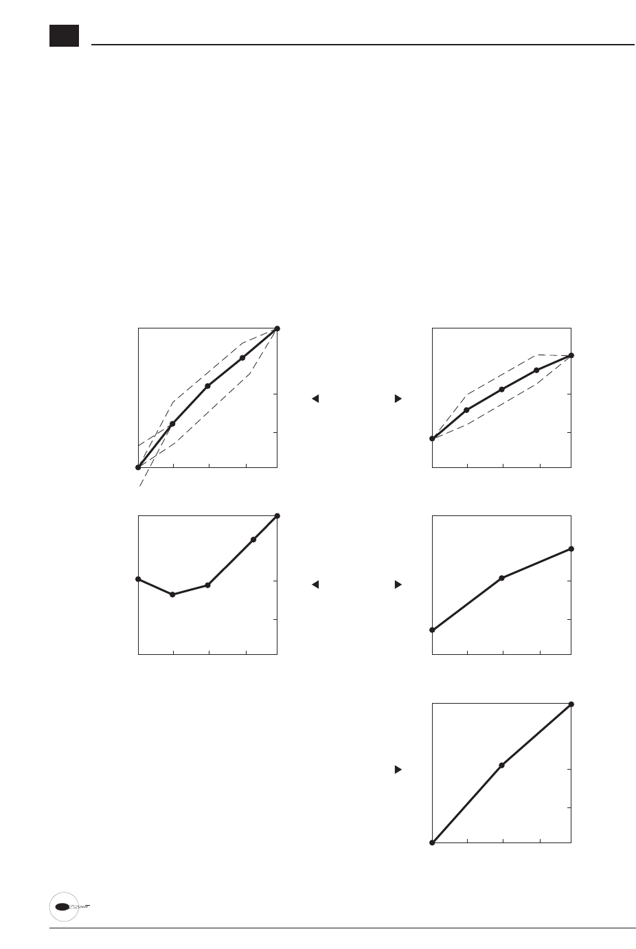
74 XP6102 - Helicopter Manual
Hovering Pitch Lever
The Hovering Pitch lever operates in the
same manner as the Hovering Throttle
lever. It is only operable while the flight
mode switch is in the NORMAL position,
and its function is to shift the middle
portion of the curve upward or
downward.
Example of Throttle Curve and Pitch
Curve Settings
An example of throttle curve and pitch
curve settings for aerobatic specifications
is shown below in the form of graphs.
Details of the curves will differ depending
on the helicopter specifications. In these
examples, the throttle open-close stroke
and autorotation pitch stroke are set 0 to
100 to ease your understanding of other
curves.
0%
50%
100%
123H
Pitch
0%
50%
100%
123H
Pitch
0%
50%
100%
123H
Pitch
0%
50%
100%
123H
Throttle
0%
50%
100%
123H
Throttle
Normal
Hover
Stunt 1
Aerobatics
Throttle
Hold
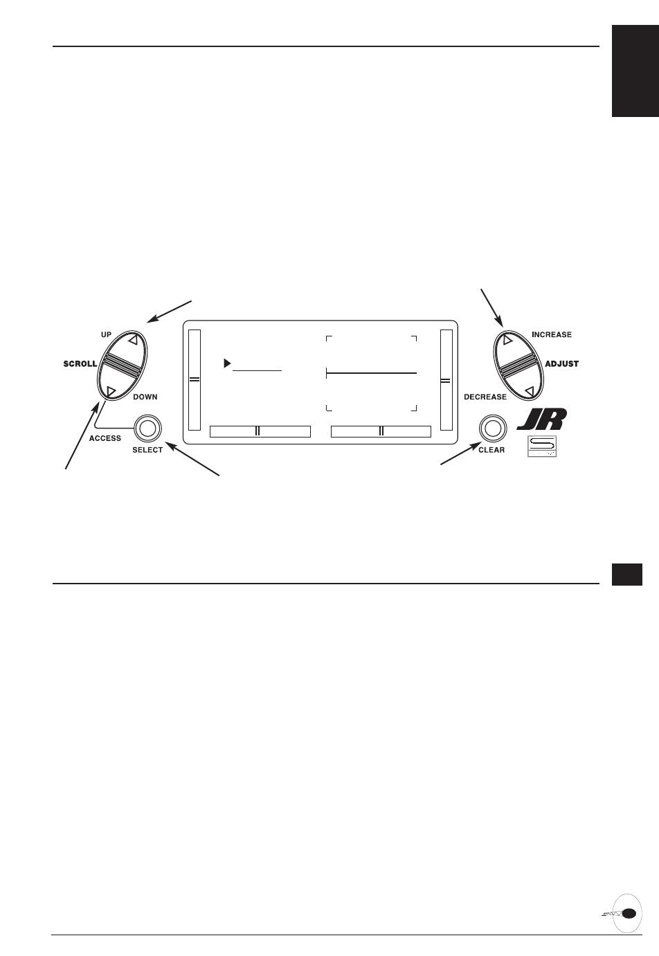
REVOLUTION MIXING (HEADING LOCK GYROS ONLY)
The Revolution Mixing function mixes tail
rotor with the Throttle and Pitch Curve
functions to counteract torque from the
main rotor blades. When set up correctly,
the helicopter should climb and descend
without a tendency to yaw in either
direction. Because torque reaction varies
with different power settings, it is
necessary to vary the tail rotor pitch at the
same time. The XP6102 offers two
separate revolution mixing programs, with
independent up and down mixing for
each - one for Flight mode position
Normal and the other for Stunt. The up
mixing adjusts the tail rotor compensation
for the mid to high throttle setting and the
down, mixing adjusts the tail rotor
compensation for the mid to low throttle
setting.
75XP6102 - Helicopter Manual
Accessing the Revolution Mixing Function
1. Place the transmitter switch in the On
position.
2. Press the Down and Select keys
simultaneously to enter the Function
Mode.
3. Press the Up or Down keys until
REVO MX appears at the top of the LCD.
4. Pressing the Select key will highlight
either the Up mix, Down mix, or the
flight mode switch position. When the
flight mode switch is in the displayed
position and the throttle stick is in the
displayed position, the flight mode will
be underlined.
5. Press the (+) key to increase the right
tail compensation or press the (-) key to
increase the left compensation. Press the
Clear key to reset to 0%.
6. This setup procedure can be used for
revolution mixing for either flight mode
switch position Normal or Stunt. The
Stunt position should be used for
forward and/or inverted compensation.
7. Access the PITCH CURVE function by
pressing the Down key.
8. Access the MX1 function by pressing
the Up key.
9. Exit the REVO MX function by pressing
the Down and Select keys
simultaneously.
[REVO MX]
NORMAL
UP 0%
DN 0%
Go to Programmable Mixing menu
Go to Pitch curve menu
Change value/Switch selection
Reset selection to default
highlight function to change
6.11

76 XP6102 - Helicopter Manual
Setting Up Revolution Mixing
Set up the helicopter so that it will hover
with the tail rotor trim centered. Establish
the helicopter into a stable hover, then
steadily increase the throttle to initiate a
steady climb. The body of the helicopter
will move in the opposite direction to the
main rotor rotation. Increase the U, or Up,
setting until the helicopter climbs with no
tendency to turn. At a safe altitude, close
the throttle; the helicopter will descend
and the body will turn in the same
direction as the main rotor rotation.
Increase the D, or down, mix until the
helicopter descends with no tendency to
turn. Throttle stick movements should be
slow, and the initial acceleration and
deceleration swings should be ignored.
The Acceleration Mixing function is
provided to compensate for the main rotor
acceleration (and deceleration) torque.
The magnitude and duration of the signal
to the tail rotor depends Upon the rate of
the throttle changes. Thus, quick, jerky
throttle inputs will yield more noticeable
tail compensation.
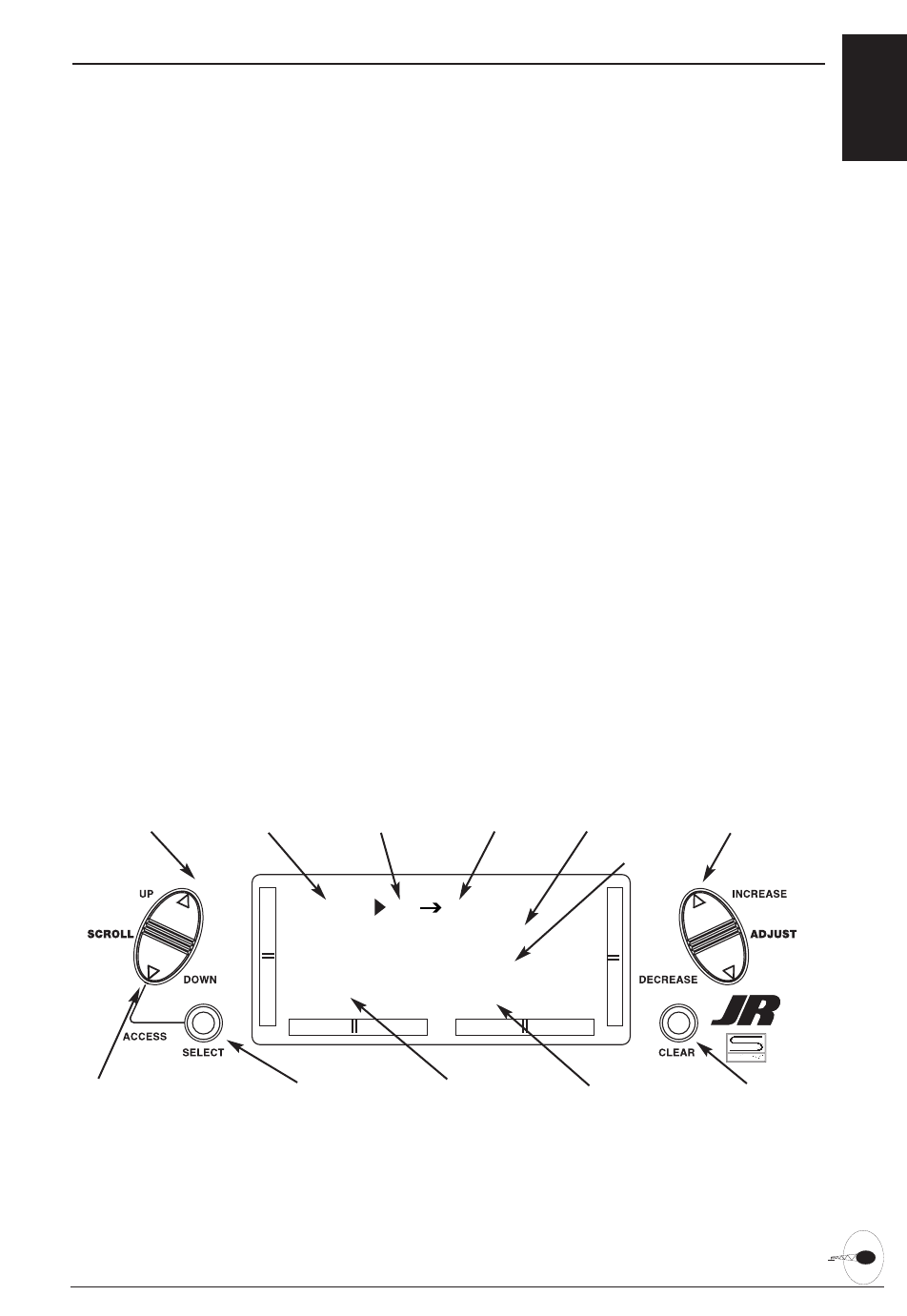
PROGRAMMABLE MIXING
The XP6102 offers two programmable
mixes to be used for any number of
different purposes. This function allows
mixing any one channel to any other
channel. This mix can remain on at all
times or be switched on and off in flight
using a number of different switches.
Mix number 1 is of the standard variety, in
that the digital trim for the master channel
only affect the master channel, and not
the slave channel. Mix number 2 is of the
"Trim Include" variety. This mix is used
any time the mix requires the slave
channels trim position to be varied when
the master channels digital trim position is
varied. An example for this type of mix
would be when dual elevator or dual
aileron servos are used and connected to
two separate channels of the system,
rather than using a single channel with a
Y-harness.
Each channel of this radio is identified by
an abbreviated name. The chart below
indicates the channel and its
corresponding abbreviation. The channel
name appearing first is known as the
"master channel" or the channel to which
you want to mix. The second number is
known as the "slave channel" or the
channel that is being mixed into the
master channel. For example, AIL ➔ RUD
would indicate aileron-to-rudder mixing.
Each time the aileron stick is moved, the
aileron will deflect, and the rudder will
automatically move in the direction and to
the value input.
Mixing is proportional, so small inputs of
the master channel will produce small
outputs of the slave channel. Each
programmable mix has a mixing "offset."
The purpose of the mixing offset is to re-
define the neutral position of the slave
channel.
77XP6102 - Helicopter Manual
[MX1] THR THR
ON OFFSET 0
0% 0%
SW ALWAYS ON
Go to Flap System menu
Go to Flap System menu Change selected value
Reset selection to default
Master Channel Slave ChannelMix number
Switch selection Switch condition
Mix percentages
Offset value
Change highlighted selection
THR: Throttle
AIL: Aileron
ELE: Elevator
RUD: Rudder
GEA: Gear
PIT: Pitch
6.12

78 XP6102 - Helicopter Manual
Accessing the Programmable Mixing Function
1. Place the transmitter switch in the On
position.
2. Press the Down and Select keys
simultaneously to enter the Function
mode.
3. Press either the Up or Down key until
MIX 1 appears in the LCD.
Selecting the Master and Slave Mixing
Channels
4. Press the (+) or (-) keys to select the
master channel.
5. Press the Select key to move the cursor
to the slave channel position.
6. Press the (+) or (-) keys to select the
slave channel.
7. Press the Select key once. The display
will continue to show the current mixing
channels at the top of the LCD, but now
an arrow will indicate the current stick
position (master) to be adjusted.
Setting the Mixing Values
8. While holding the master stick in the
direction you want to mix, press the (+)
or (-) keys to increase or decrease the
mixing value for the slave channel. The
value in the LCD will change to display
the current mix value selected. Next,
hold the master stick to the other side to
adjust the mix for the other direction.
Setting the Mixing Switch Activation
9. Press the Channel key once again. The
LCD with "ALWAYS ON" indicates the
current switch that this mix is currently
selected to always be active (ON).
Mixing Operation and Switches
Each mixing program can be turned on
and off by a lever or switch. The levers
and switches that can be selected for
program mixing are tabulated at the right
with their abbreviations appearing on the
display and their corresponding positions.
The mix switch options are:
ALWAYS ON
RIGHT FWD
RIGHT REA
LEFT FWD
LEFT REA
AILE D/R
ELEV D/R
Setting the Mixing Channel Offset
1. Press the Select key until offset is
highlighted. The display will show the
current mixing channels at the top of the
LCD, with the word "OFFSET" in the
center of the LCD. The value to the right
is the mixing Offset neutral point,
currently 0.
2. A new value for the offset can be
selected using the (+) or (-) keys. This is
the new neutral point for the slave
channel (Point that the mix is activated).
Press the Clear key to reset the value
back to 0.
3. Press the Down and Select keys
simultaneously to exit the
Programmable Mix function.
With a little practice, programmable
mixing will become easier to
understand. Mixing is only limited
by your imagination.

79XP6102 - Helicopter Manual
Programmable Mixing Offsets
Any stick position of the master channel
can be determined as the basic center
point of mixing. The basic point is the
position of the master channel stick,
control switch, or knob where you set the
mix value and the direction of mixing.
To set the basic point of mixing, hold the
master channel in the desired position and
press the Clear key. The display will
indicate offset value from neutral;
however, mixing value at the determined
position would indicate zero.
When properly adjusted, your heli should
track across the sky at full speed with no
correction needed. The X-378 has three
programmable mixes that can free mix
any two channels. Following are some
examples of where this free mixing is
used.
Pitch-to-Elevator Mixing
At full throttle, fast forward flight, most
helicopters pitch either up or down. The
XP6102 has active digital trims in each
flight mode to correct this. However, at
intermediate speeds (e.g., 5/8 throttle) this
pitching tendency is reduced.
Many top pilots use a combination of
elevator stunt trim and Pitch-to-Elevator
Mixing. Mix pitch (channel 6) to Elevator
(channel 3) and select switch position 1, 2
so that the mixing is turned on in Flight
mode 1 and 2.
Then, hover your helicopter. Using
forward cyclic only, push your heli into
forward flight, but don’t change the pitch
or throttle settings. After transitioning into
forward flight, notice the direction the
nose pitches. Correct this with stunt trim
elevator until no pitching occurs at this
throttle pitch setting.
Finally, fly your helicopter at full
throttle/pitch in fast forward flight. If the
nose pitches up, feed in down pitch to
elevator mixing until straight flight is
achieved. When properly adjusted, the
heli will fly straight and level, hands off,
at all throttle pitch settings.
Rudder-to-Throttle Mixing
During 540 stall turns and fast pirouettes,
the tail rotor absorbs power and the main
rotor rpm decays. This can be
compensated for by mixing rudder-to-
throttle so that when rudder is applied, the
throttle is advanced. It usually takes about
15% right mixing and 10% left mixing.
Please note that when using any
programmable mix coupled to the throttle
channel of the X-378, it will be necessary
to increase the high throttle travel position
of the channel to the maximum 150% to
prevent over-traveling of the throttle by
the addition of the programmable mix.
Rudder-to-Throttle Mixing
When doing a roll or at anytime hard-over
cyclic is used, the main rotor’s rpm can
decay due to increased loads. A way
around this is to mix aileron to throttle so
that when the aileron is displaced, throttle
is added. Use about 10-30 % in both
directions.
Please note that when using any
programmable mix coupled to the throttle
channel of the XP6102, it will be
necessary to increase the high throttle
travel position of the channel to the
maximum 150% to prevent over-traveling
of the throttle by the addition of the
programmable mix.
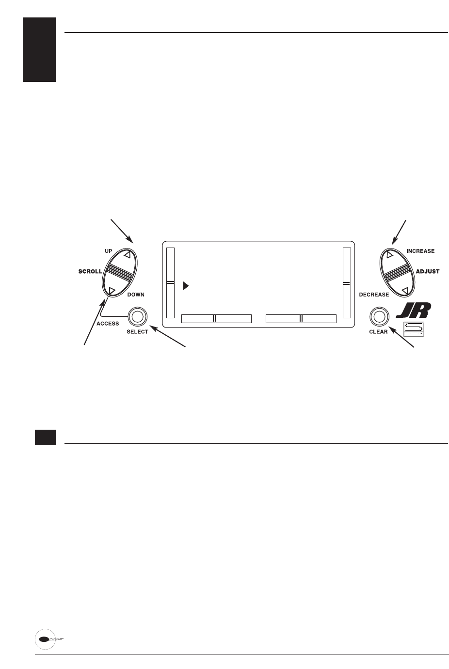
80 XP6102 - Helicopter Manual
FAIL SAFE
The Fail-Safe/Hold function is available
only when you use the XP6102 transmitter
in PCM modulations. This function is
designed to help minimize damage to
your aircraft during a loss of signal to the
receiver. The servos either assume the fail-
safe presets or hold their last good signal
position.
As noted earlier, if you are in the PPM
modulation, the Fail-Safe/Hold function
is not applicable. Therefore, the Fail-
Safe/Hold function will not appear on
your LCD screen menu while in the
PPM mode. Refer to the Modulation
Selection section for more information
pertaining to the broadcast signal of
your XP6102 transmitter.
Accessing the Fail Safe Function
1. Place the transmitter power switch in
the On position.
2. Access the Function mode. To do so,
press the Down and Select keys
simultaneously. Press either the Up or
Down key until FAIL SAFE appears in
the upper portion of the LCD screen.
3. Use the Select key to highlight the
servo function to set.
4. Use the (+) or (-) keys to toggle
between servo hold or setting the servo
position.
5. When using the servo setting position,
move the corresponding control stick to
the position where you want the servo if
the radio enters into the fail safe mode.
Press the Clear key to have the
transmitter memorize the stick position.
6. Repeat steps 4 and 5 until all six
controls have been set.
7. Access the SERVO TRAVEL screen by
pressing the Up key.
8. Access the MIXING FUNCTIONS
function by pressing the Up key.
9. Exit the FAIL SAFE function by pressing
the Down and Select keys
simultaneously.
[FAIL SAFE]
TH HLD AI HLD
EL HLD RU HLD
GE HLD FL HLD
Go to Programmable
Mixing menu
Go to Servo Travel Screen Change from servo
hold to stick selection
Invoke stick selection
Change highlighted selection
6.13
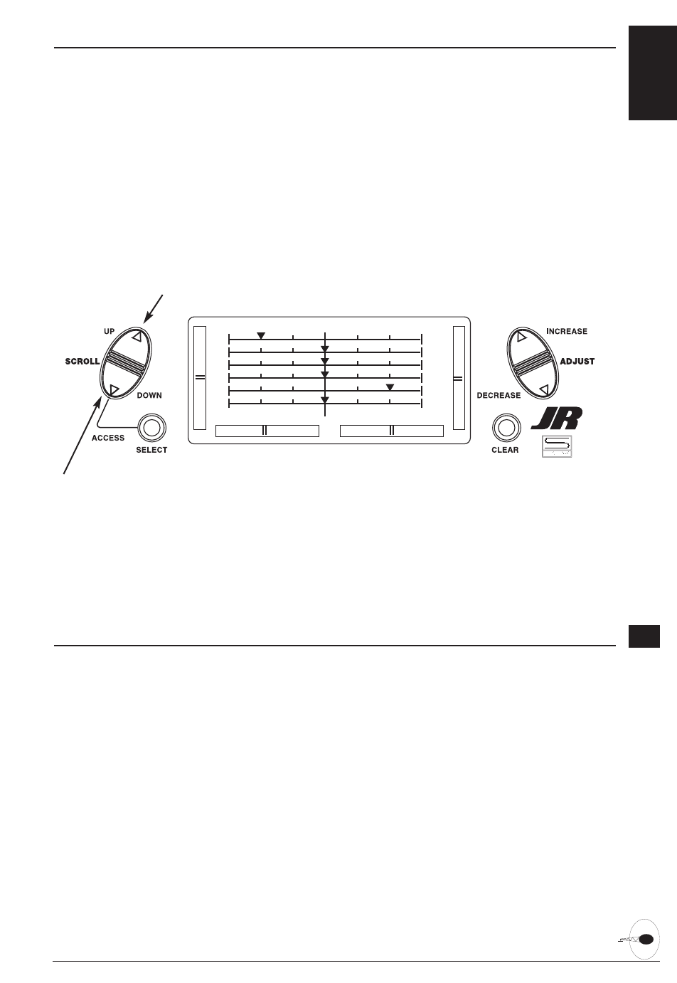
81XP6102 - Helicopter Manual
SERVO TRAVEL SCREEN
The Servo Travel Screen is used to verify
the stick movements of the transmitter. It can also be used to verify the mixing
functions have been performed correctly
without the need to turn on the aircraft.
Accessing the Servo Travel Screen
1. Place the transmitter power switch in
the On position.
2. Access the Function mode. To do so,
press the Down and Select keys
simultaneously. Press either the Up or
Down key until the SERVO TRAVEL
screen appears.
3. Move the sticks. The the indicators
correspond to the following:
Indicator 1: Throttle
Indicator 2: Aileron
Indicator 3: Elevator
Indicator 4: Rudder
Indicator 5: Gear
Indicator 6: Pitch
4. Access the D/R & EXP screen by
pressing the Up key.
5. Access the FAIL SAFE function by
pressing the Up key.
6. Exit the SERVO TRAVEL screen function
by pressing the Down and Select keys
simultaneously.
1
3
5
2
4
6
Go to Fail Safe menu
Go to D/R & Exp menu
6.14
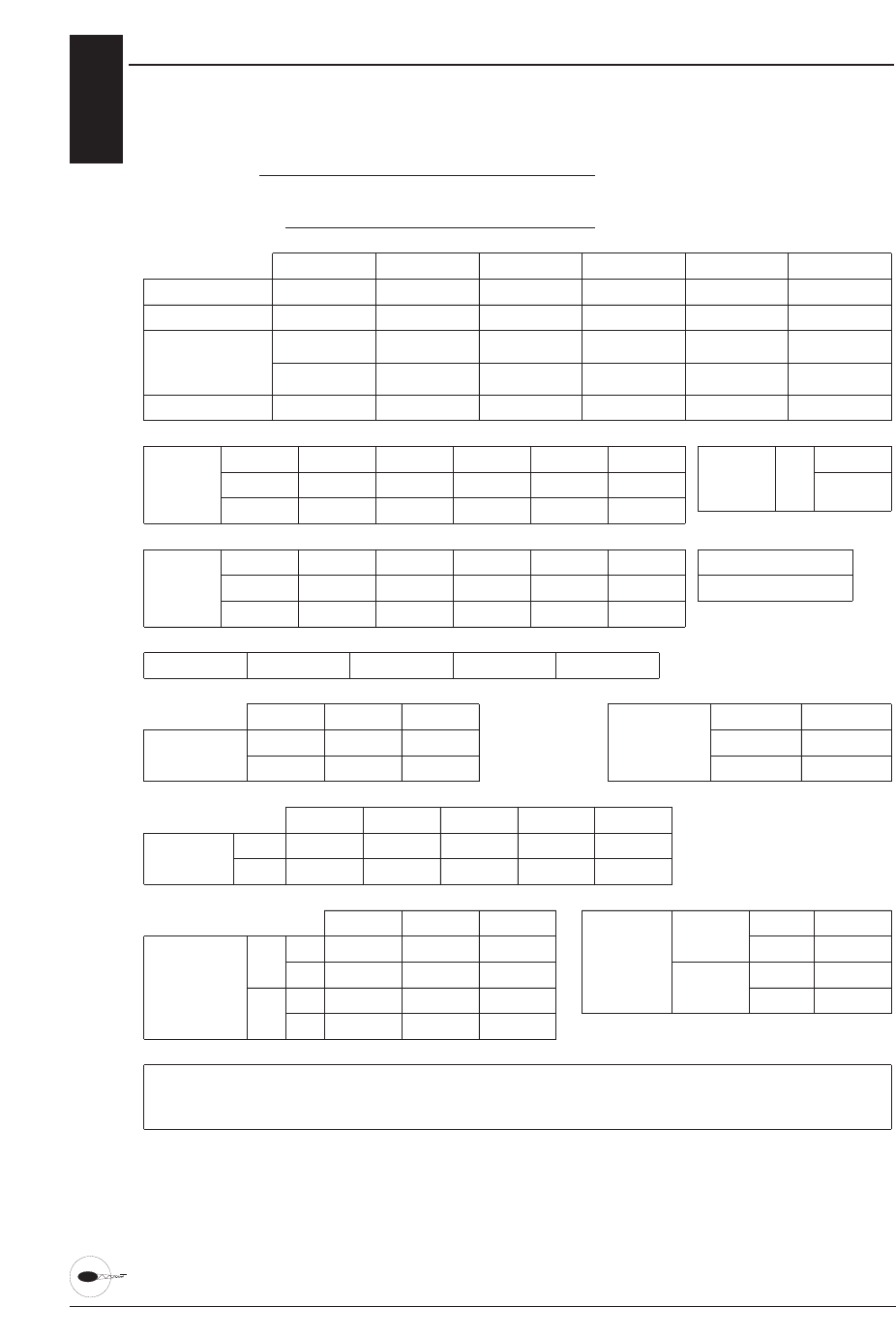
82 XP6102 - Helicopter Manual
XP6102 DATA SHEET
REVERSE SW
THRO
TRAVEL ADJUST
FAIL SAFE (PCM)
SUB TRIM
H %
L %
AILE
L %
R %
ELEV
U %
D %
RUDD
L %
R %
GEAR
+ %
– %
PITCH
H %
L %
AILE
DUAL RATE
•
EXPO
%
%
%
%
ELEV
%
%
%
%
RUDD
%
%
%
%
D/R
EXP
D/R
EXP
0
1
D/R
GEAR
FL-M
SWITCH
SELECT
CHANNEL
PROGRAM
MIX
SW +POS
%
%
–POS OFFSET
%
%
MIX 1
MIX 2
–
–
THROTTLE
HOLD
MODULATION
NOTES:
PPM • SPCM
XP6102 DATA SHEET – HELI
MODEL NUMBER
MODEL NAME
ON
•
OFF
POSITION
%
%
%
%
UP
DOWN
UP
DOWN
REVO MIX
NORMAL
STUNT
AILE ELEV PITCH
REV R•N
%
REV R•N
%
REV R•N
%
SWASH
MIX
SWASH TYPE NORMAL 90° CCPM 120° CCPM 180° CCPM
R • N R • N R • N R • N R • NR • N
THROTTLE
CURVE NORMAL
STUNT
P-LOW P-1 P-MID P-3 P-HIGH
PITCH
CURVE NORMAL
STUNT
P-LOW P-1 P-MID P-3 P-HIGH
6.13
Feel free to make photocopies of the data sheet for use with all your models.

SERVO PRECAUTIONS x
• Do not lubricate servo gears or motors.
• Do not overload retract servos during
retracted or extended conditions. Make
sure they are able to travel their full
deflection. Overloading or stalling a
servo can cause excessive current drain.
• Make sure all servos move freely
through their rotations and no linkages
hang up or bind. A binding control
linkage can cause a servo to draw
excessive current. A stalled servo can
drain a battery pack in a matter of
minutes.
• Correct any control surface "buzz" or
"flutter" as soon as it is noticed in flight,
as this condition can destroy the
feedback potentiometer in the servo. It
may be extremely dangerous to ignore
such "buzz" or "flutter."
• Use the supplied rubber grommets and
brass servo eyelets when mounting your
servos. Do not over-tighten the servo
mounting screws, as this negates the
dampening effect of the rubber
grommets.
• Ensure the servo horn is securely
fastened to the servo. Use only the JR
servo arm screws provided; the size is
different from other manufacturers.
• Discontinue to use servo arms when
they become "yellowed" or discolored.
Such servo arms may be brittle and can
snap at any time, possibly causing the
aircraft to crash.
•Check all related mounting screws and
linkages frequently. Aircraft often vibrate,
causing linkages and screws to loosen.
83XP6102 - Manual
S
E
C
T
I
O
N
IV
•
I
M
P
O
R
T
A
N
T
I
N
F
O
R
M
A
T
I
O
N
GENERAL NOTES x
Radio controlled models are a great
source of pleasure. Unfortunately, they
can also pose a potential hazard if not
operated and maintained properly. It is
imperative to install your radio control
system correctly. Additionally, your level
of piloting competency must be high
enough to ensure that you are able to
control your aircraft under all conditions.
If you are a newcomer to radio controlled
flying, please seek help from an
experienced pilot or your local hobby
shop.
Safety Do's and Don'ts for Pilots
• Ensure your batteries have been
properly charged prior to initial flight.
• Keep track of the time the system is
turned on so you will know how long
you can safely operate your system.
• Perform a ground range check prior to
the initial flight of the day. See the
"Daily Flight Checks Section" for
information.
• Check all control surfaces prior to each
takeoff.
• Use frequency flags.
• Do not fly your model near spectators,
parking areas or any other area that
could result in injury to people or
damage of property.
• Do not fly during adverse weather
conditions. Poor visibility can cause
disorientation and loss of control of your
aircraft. Strong winds can cause similar
problems.
• Do not fly unless your frequency is
clear.
Warning: Only one transmitter at a time
can operate on a given frequency. If
you turn on your transmitter while
someone else is operating a model on
your frequency, both pilots will lose
control of their models. Only one
person can use a given frequency at a
time. It does not matter if it is AM,
FM or PCM—only one frequency at a
time.
• Do not point the transmitter antenna
directly toward the model. The radiation
pattern from the tip of the antenna is
inherently low.
• Do not take chances. If at any time
during flight you observe any erratic or
abnormal operation, and immediately
and do not resume flight until the cause
of the problem has been ascertained and
corrected. Safety can never be taken
lightly.

xFEDERAL AVIATION ADMINISTRATION
1. Purpose
This advisory outlines safety standards for
operations of model aircraft. We
encourage voluntary compliance with
these standards.
2. Background
Attention has been drawn to the increase
in model aircraft operation. There is a
need for added caution when operating
free flight and radio controlled craft in
order to avoid creating a noise nuisance
or a potential hazard to full-scale aircraft
and persons and/or property on the
surface.
3. Operating Standards
Modelers generally are concerned with
safety and exercise good judgment when
flying model aircraft. However, in the
interest of safer skies, we encourage
operators of radio controlled and free
flight models to comply with the following
standards:
a. Exercise vigilance in locating full-
scale aircraft (get help if possible) so
as not to create a collision hazard.
b. Select an operating site at sufficient
distance from populated areas so you
do not create a noise problem or a
potential hazard.
c. Do not fly higher than 400 feet
above the surface.
d. Always operate more than three
miles from the boundary of an airport
unless you are given permission to be
closer by the appropriate air traffic
control facility in the case of an
airport for which a control zone has
been designated or by the airport
manager in the case of other airports.
e. Do not hesitate to ask for
assistance in complying with these
guidelines at the airport traffic control
tower or air route traffic control
center nearest the site of your
proposed operation.
Information Provided By:
Director, Air Traffic Service Federal
Aviation Administration, Washington, D.C.
84 XP6102 - Manual
xDAILY FLIGHT CHECKS
1. Check the battery voltage on both the
transmitter and the receiver battery
packs. Do not fly below 9.0V on the
transmitter or below 4.7V on the
receiver. To do so can crash your aircraft.
Note: When you check these batteries,
ensure that you have the polarities
correct on your expanded scale
voltmeter.
2. Check all hardware (linkages, screws,
nuts, and bolts) prior to each day's flight.
Be sure that binding does not occur and
that all parts are is properly secured.
3. Ensure that all surfaces are moving in
the proper manner.
4. Perform a ground range check before
each day's flying session. The range
check should be as follows:
• Do not extend the transmitter antenna at
this time. Turn the transmitter "on."
• Turn the model "on."
• Slowly walk away from the model while
moving the control surfaces. The aircraft
should function properly at a distance of
60-75 feet.
5. Prior to starting your aircraft, turn off
your transmitter, then turn it back on. Do
this each time you start your aircraft. If
any critical switches are on without your
knowledge, the transmitter alarm will
warn you at this time.
6. Check that all trim levers are in the
proper location.
7. All servo pigtails and switch harness
plugs should be secured in the receiver.
Make sure that the switch harness moves
freely in both directions.

FREQUENCY CHART x
72 MHz r equir es no special license to operate.
85XP6102 - Manual
Ch.No. Frequency
11 72.010
12 72.030
13 72.050
14 72.070
15 72.090
16 72.110
17 72.130
18 72.150
19 72.170
20 72.190
21 72.210
22 72.230
23 72.250
24 72.270
25 72.290
26 72.310
27 72.330
28 72.350
29 72.370
30 72.390
31 72.410
32 72.430
33 72.450
34 72.470
35 72.490
Low Band 72 MHz
Ch.No. Frequency
36 72.510
37 72.530
38 72.550
39 72.570
40 72.590
41 72.610
42 72.630
43 72.650
44 72.670
45 72.690
46 72.710
47 72.730
48 72.750
49 72.770
50 72.790
51 72.810
52 72.830
53 72.850
54 72.870
55 72.890
56 72.910
57 72.930
58 72.950
59 72.970
60 72.990
High Band 72 MHz
Transmitter Crystal Replacement Notice:
The Federal Communications Commission
(FCC) requires that changes in transmitter
frequency must be performed only by an
authorized service technician (Horizon
Service Center).
Any transmitter frequency changes made
by a non-certified technician may result in
a violation of FCC rules.
Channels 12–14 are not available through
JR.

xWARRANTY INFORMATION
Important: Be sure to keep your original
dated sales receipt, as you will be
required to provide proof-of -
purchase date for the equipment to
be serviced under warranty.
Warranty Coverage
Your new JR Remote Control Radio
System is warranted to the original
purchaser against manufacturer defects in
material and workmanship for an
unprecedented 3 years from the date of
purchase. During this period, Horizon
Service Center will repair or replace, at
our discretion, any component that is
found to be factory defective at no cost to
the purchaser. This warranty is limited to
the original purchaser of the unit and is
not transferable.
This warranty does not apply to any unit
that has been improperly installed,
mishandled, abused or damaged in a
crash, or to any unit that has been
repaired or altered by any unauthorized
agencies. Under no circumstances will the
buyer be entitled to consequential or
incidental damages. This limited warranty
gives you specific legal rights; you also
have other rights, which may vary from
state to state. As with all fine electronic
equipment, do not subject your radio
system to extreme temperatures, humidity
or moisture. Do not leave it in direct
sunlight for long periods of time.
Repair Service Directions
In the event that your JR radio needs
service, please follow the instructions
listed below.
1. Check all on/off switches to be sure
they are off. This will speed the repair
process of checking battery condition.
2. Return your system components only
(transmitter, receiver, servos, etc.). Do
not return your system installed in a
model aircraft, car, boat, etc.
3. Preferably, use the original
carton/packaging (molded foam
container), or equivalent, to ship your
system. Do not use the system carton
itself as a shipping carton, you should
package the system carton within a
sturdy shipping container using
additional packing material to safeguard
against damage during transit. Include
complete name and address information
inside the carton, as well as clearly
writing it on the outer label/return
address area.
4. Include detailed information explaining
your operation of the system and
problem(s) encountered. Provide an
itemized list of equipment enclosed and
identify any particular area/function,
which may better assist our technicians
in addressing your concerns. Within
your letter, advise us of the payment
method you prefer to use. Horizon
Service Center accepts VISA or
MasterCard. Please include your card
number and expiration date. Date your
correspondence, and be sure your
complete name and address appear on
this enclosure.
5. Include your name, mailing address,
and a phone number where you can be
reached during the business day.
Warranty Repairs
To receive warranty service, you must
include a copy of your original dated sales
receipt to verify your proof-of-purchase
date. Providing that warranty conditions
have been met, your radio will be
repaired without charge.
Normal Non-Warranty Repairs
Should your repair cost exceed 50% of
the retail purchase cost, you will be
provided with an estimate advising you of
your options.
Mail your system to:
Horizon Service Center
4105 Fieldstone Road
Champaign, IL 61822
Phone: (217) 355-9511
86 XP6102 - Manual

NOTES: x
87XP6102 - Manual

#6209
© 2003, Horizon Hobby, Inc.
4105 Fieldstone Road
Champaign, Illinois 61822
(877) 504-0233
www.horizonhobby.com