Horizon Hobby XP662 JR XP662 6 Channel FM Radio System User Manual XP662 Manual
Horizon Hobby, LLC JR XP662 6 Channel FM Radio System XP662 Manual
UserManual.wiki
>
Horizon Hobby
>
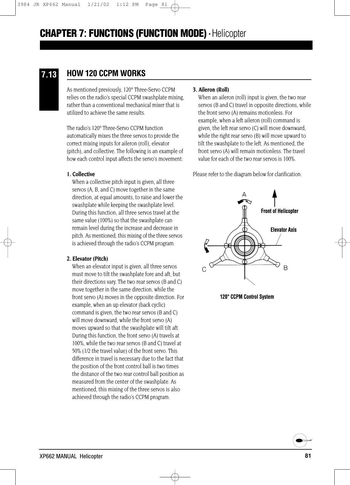
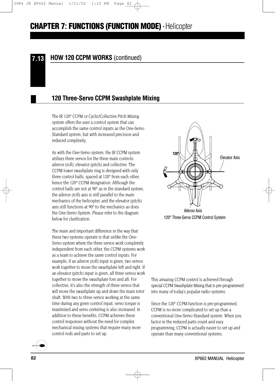
XP662 User Manual
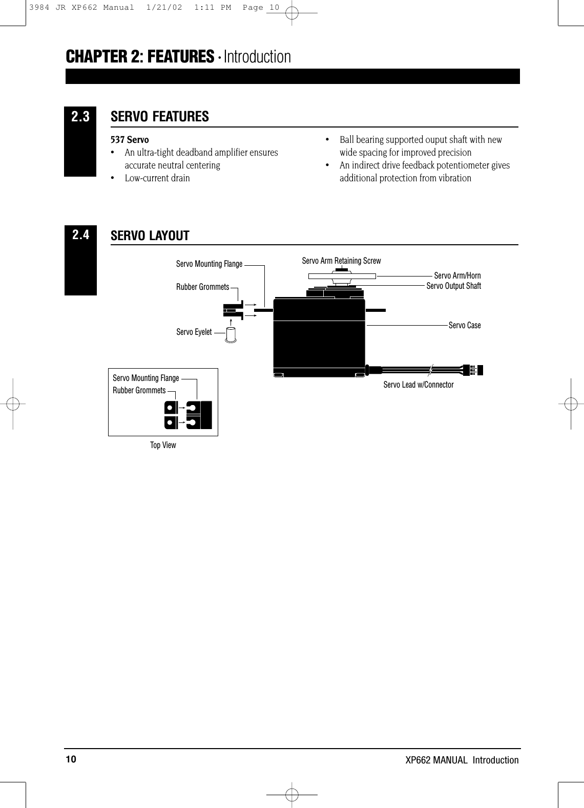
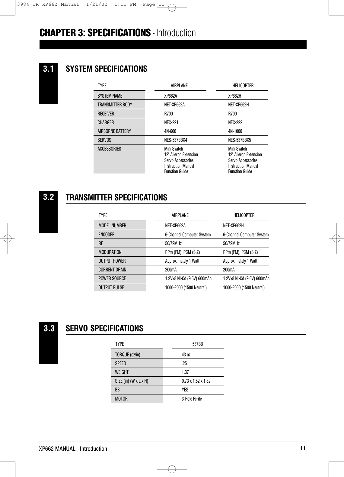
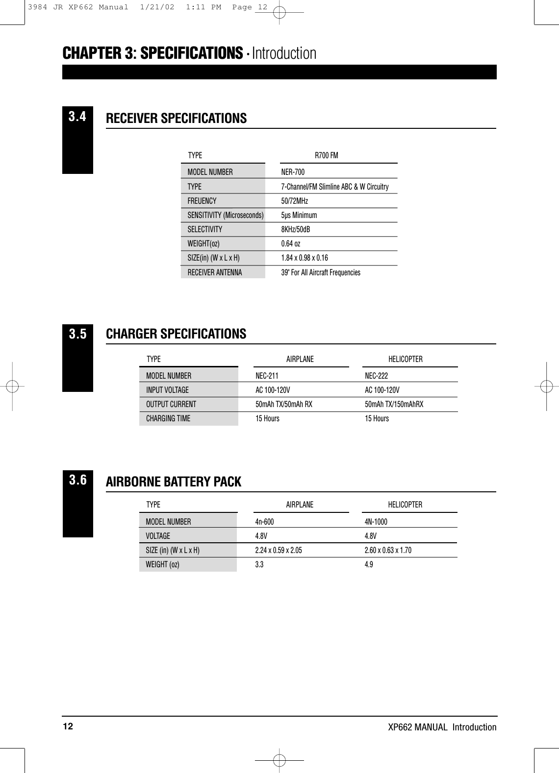
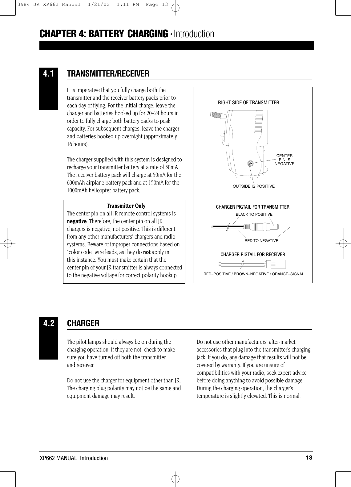
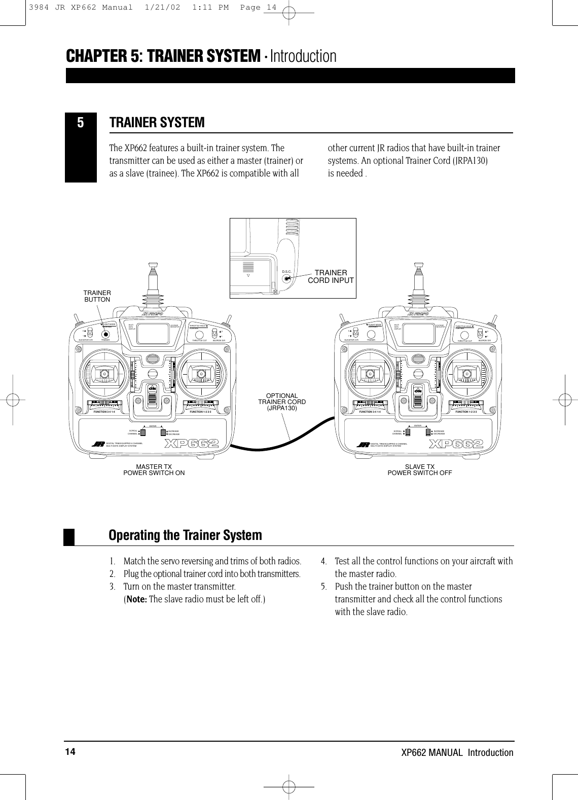
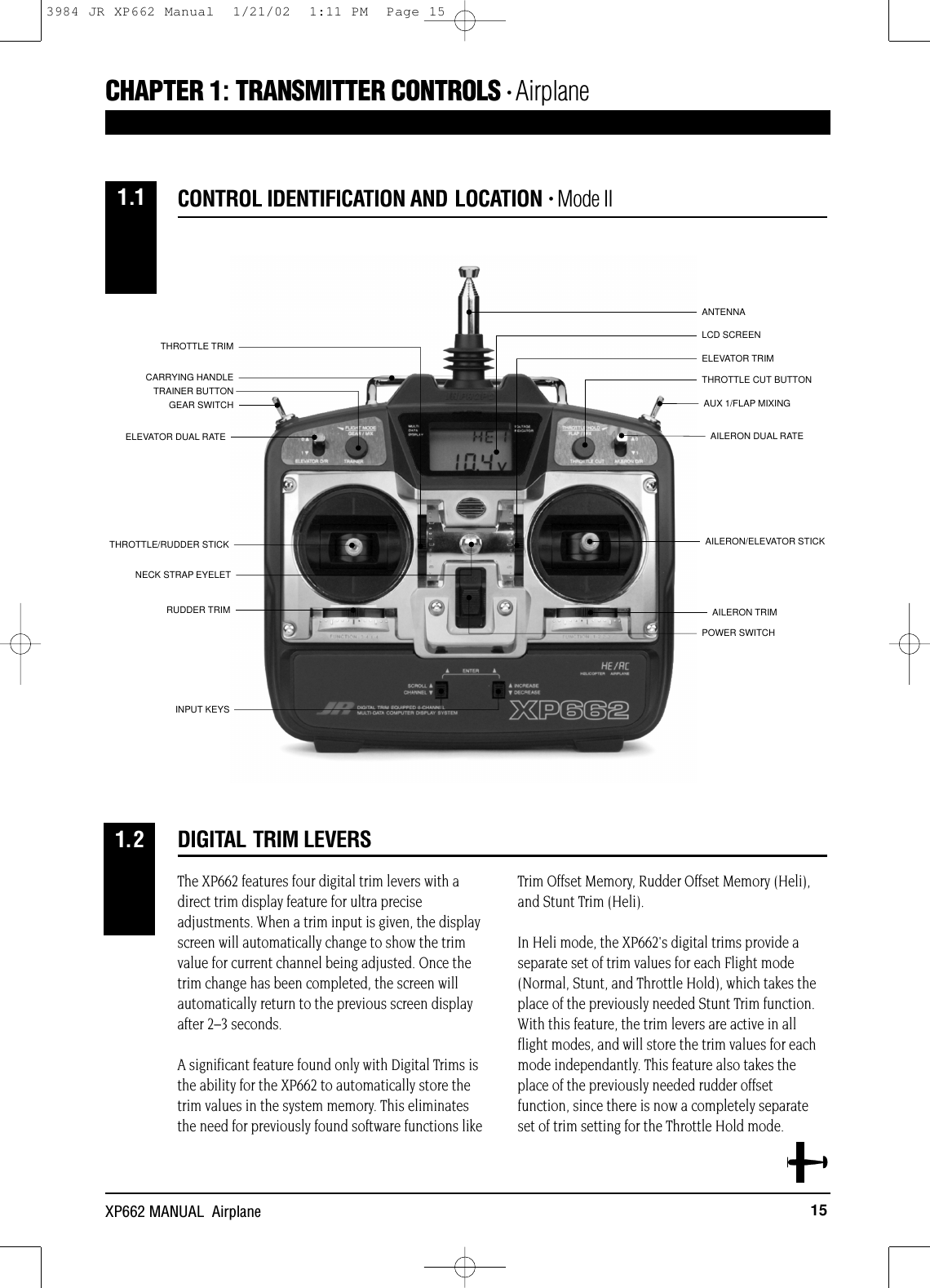
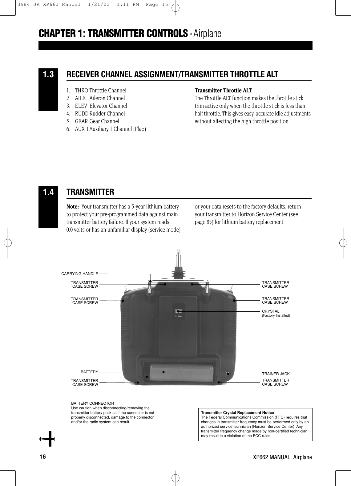
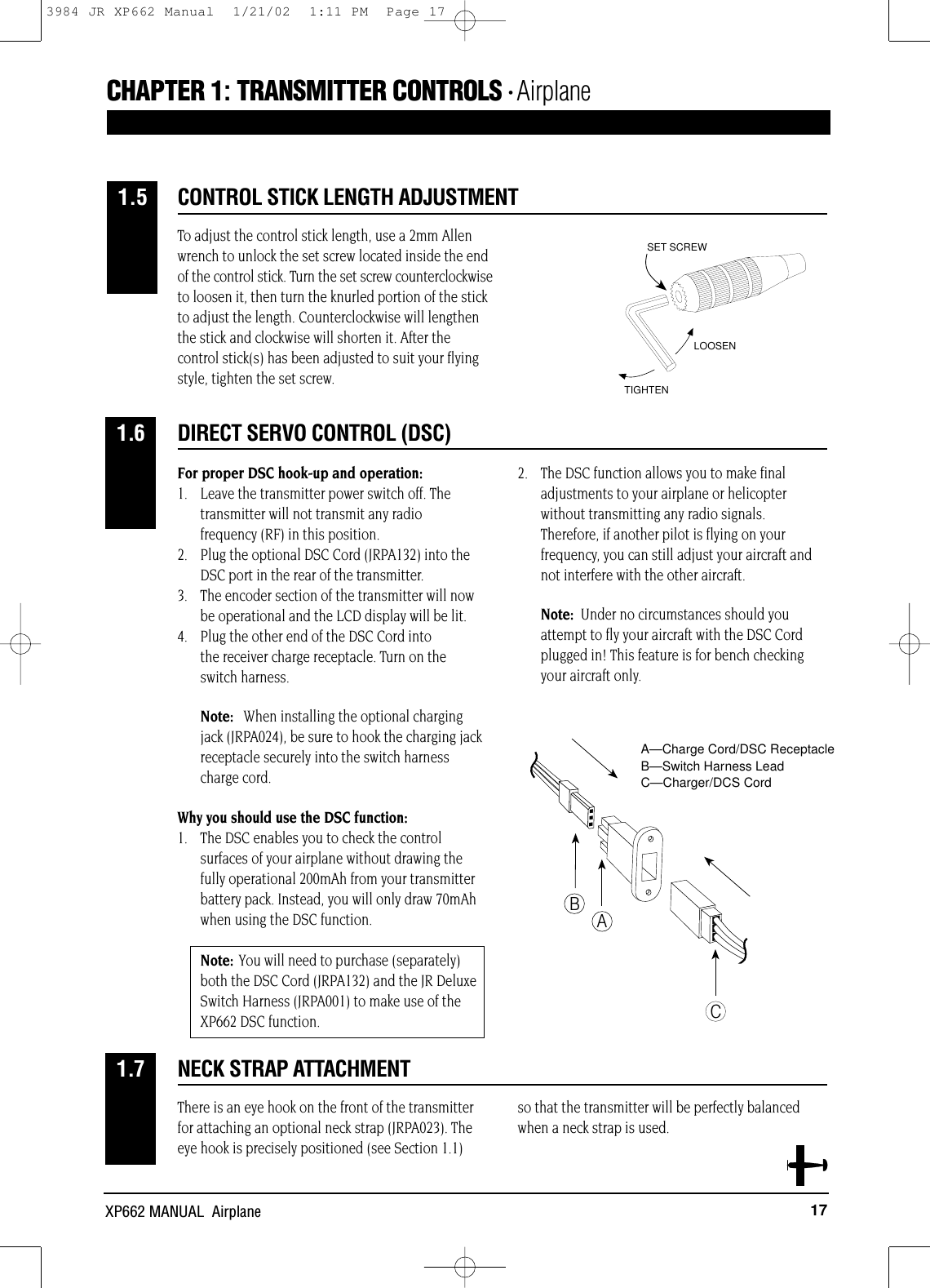
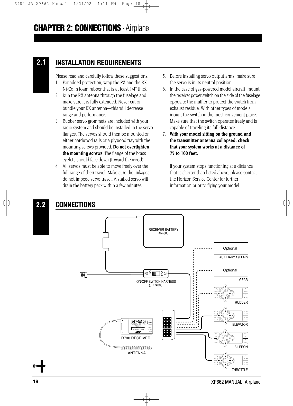
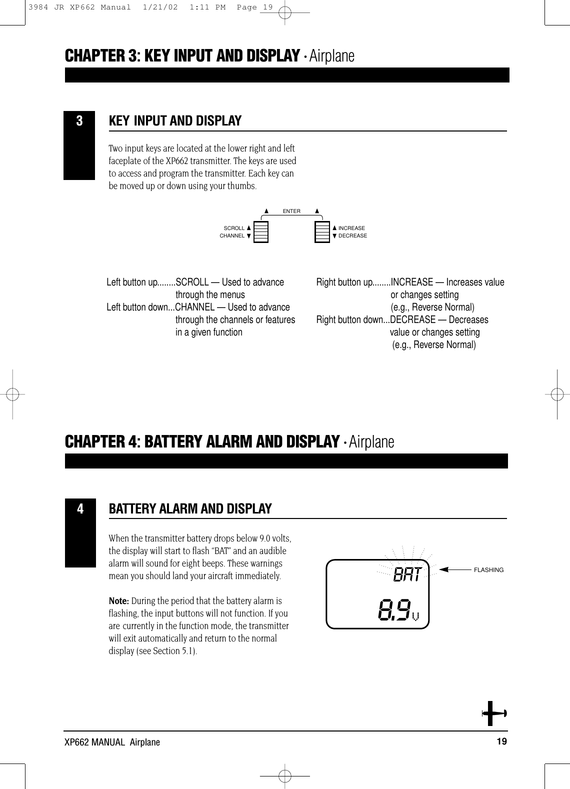
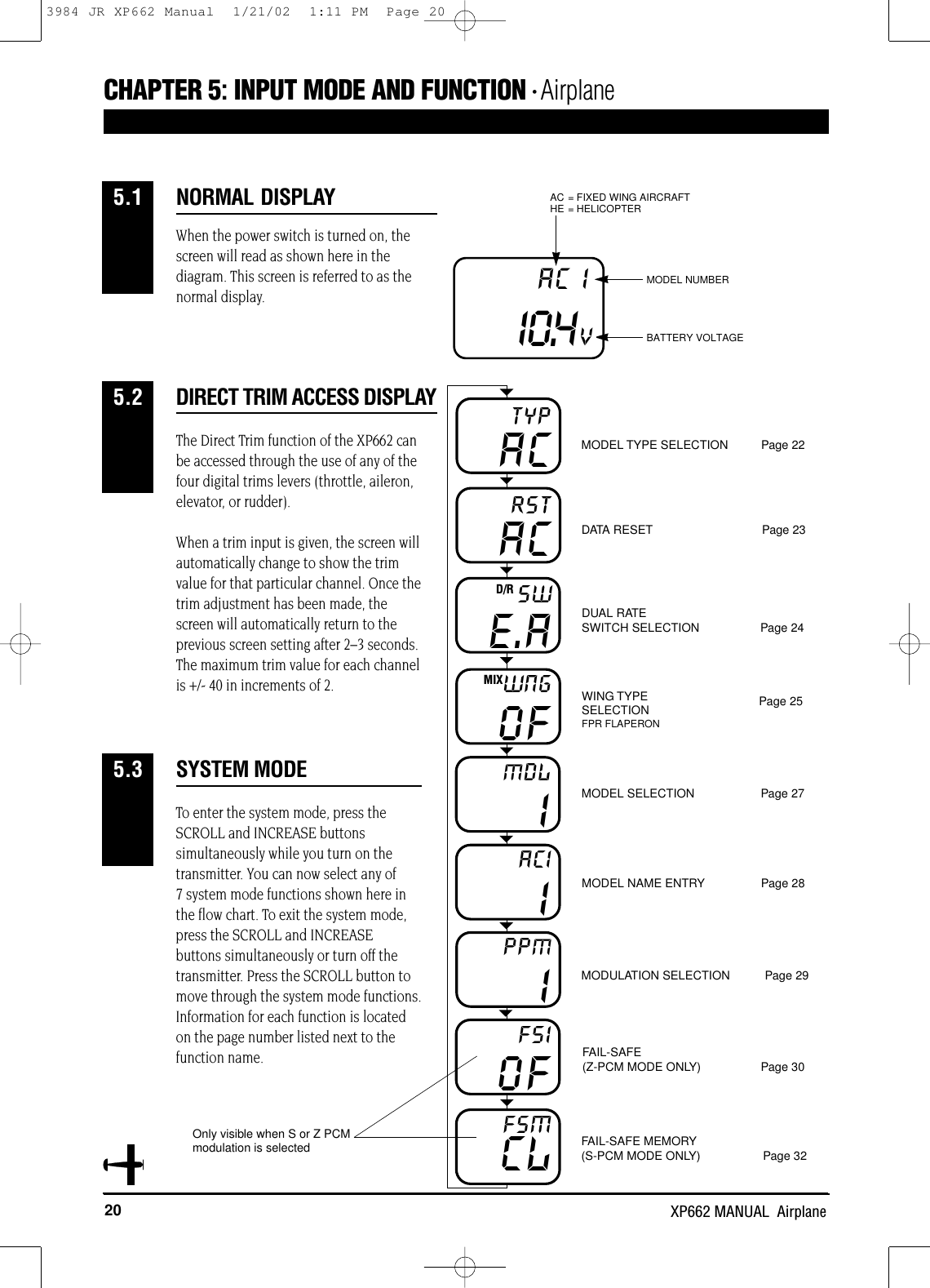
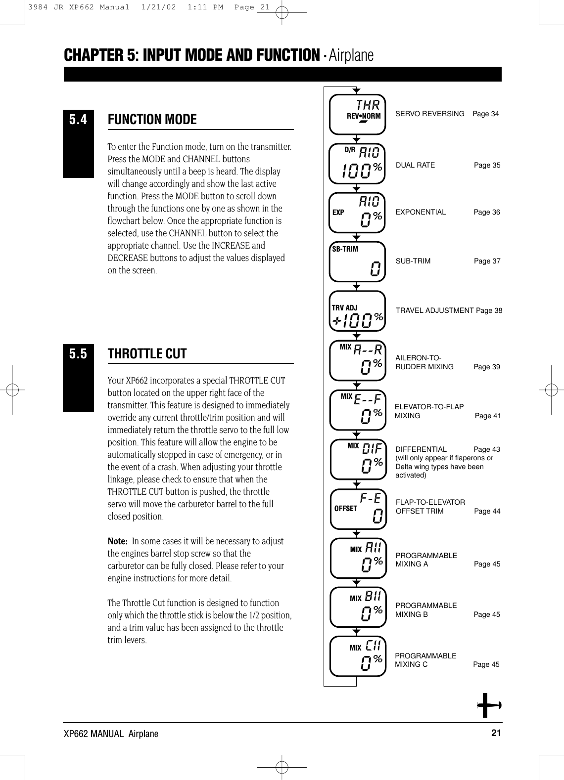
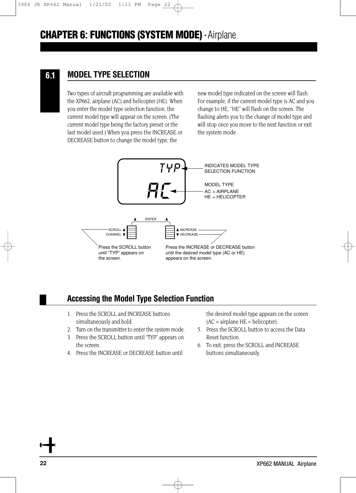
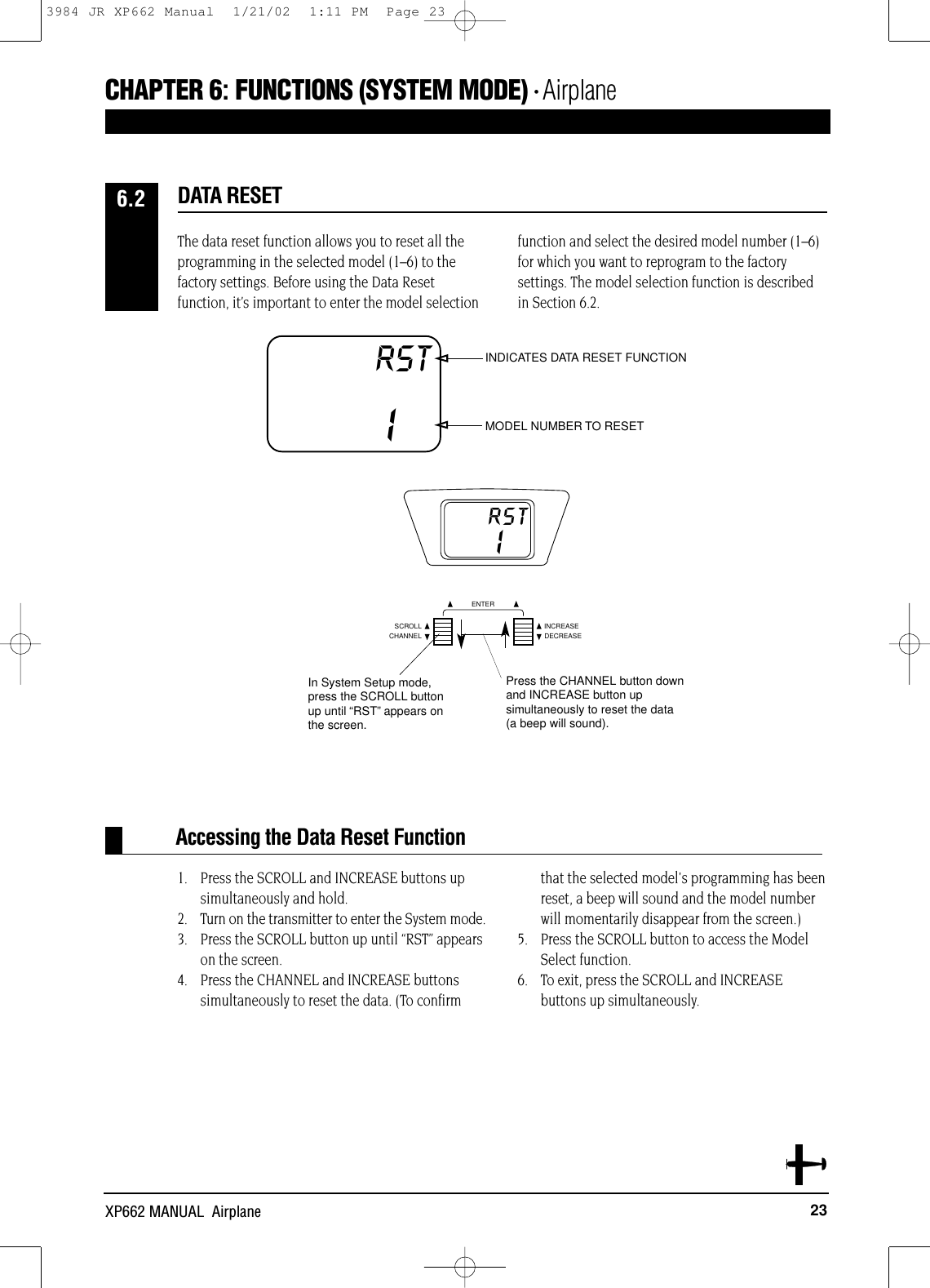
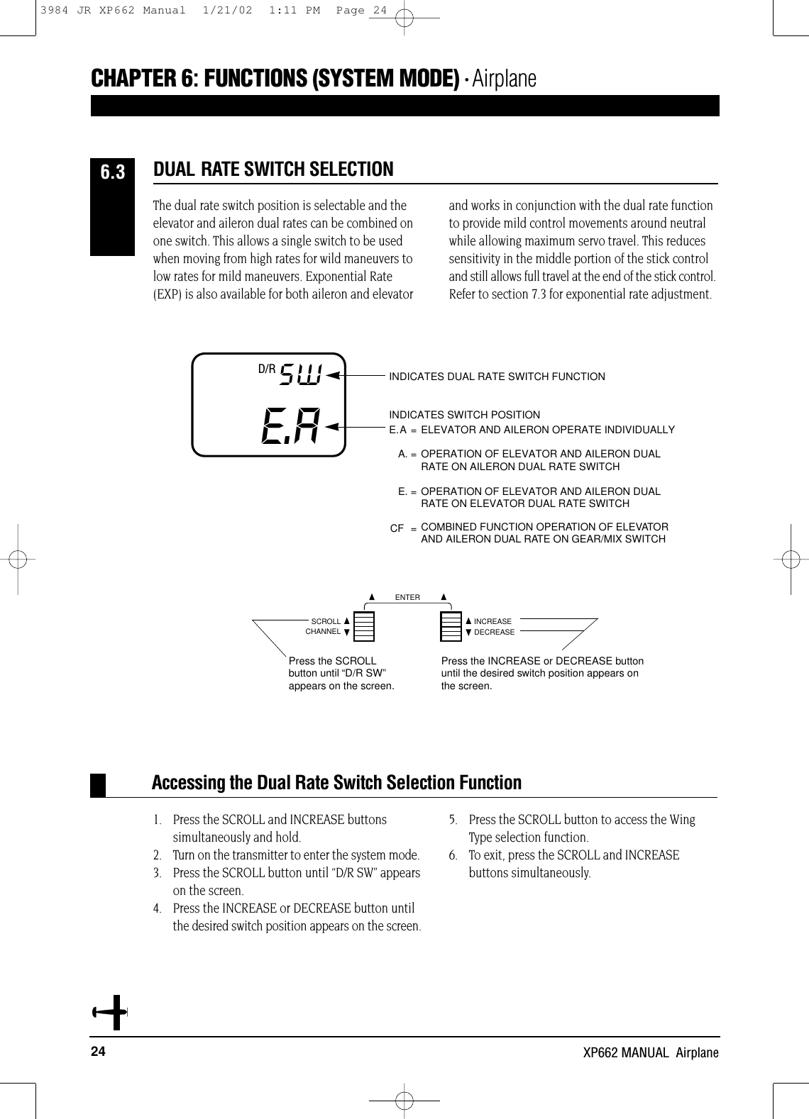
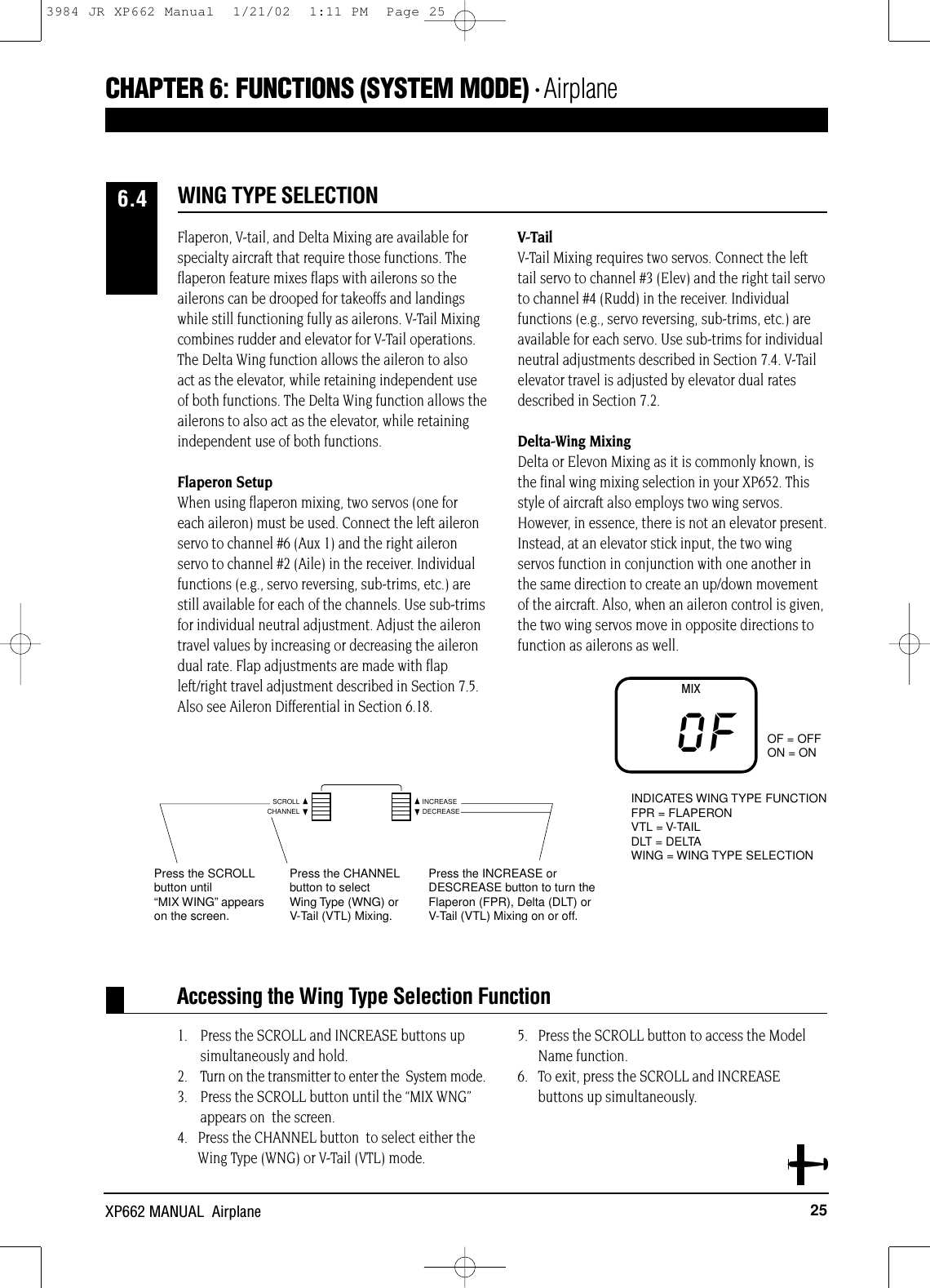
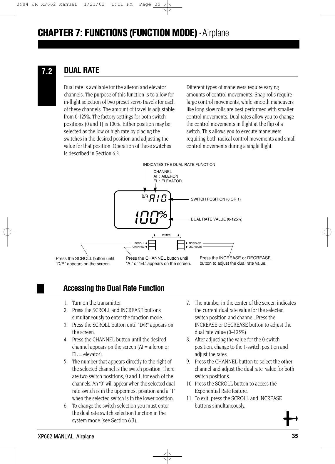
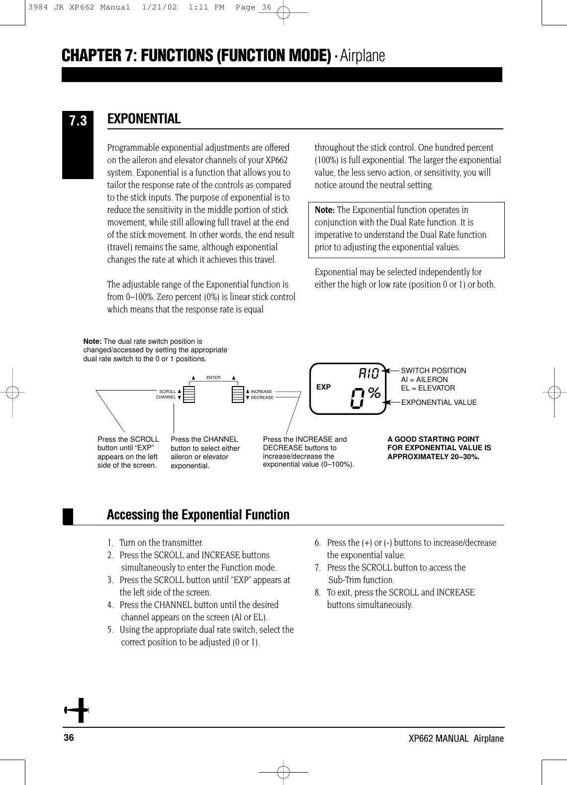
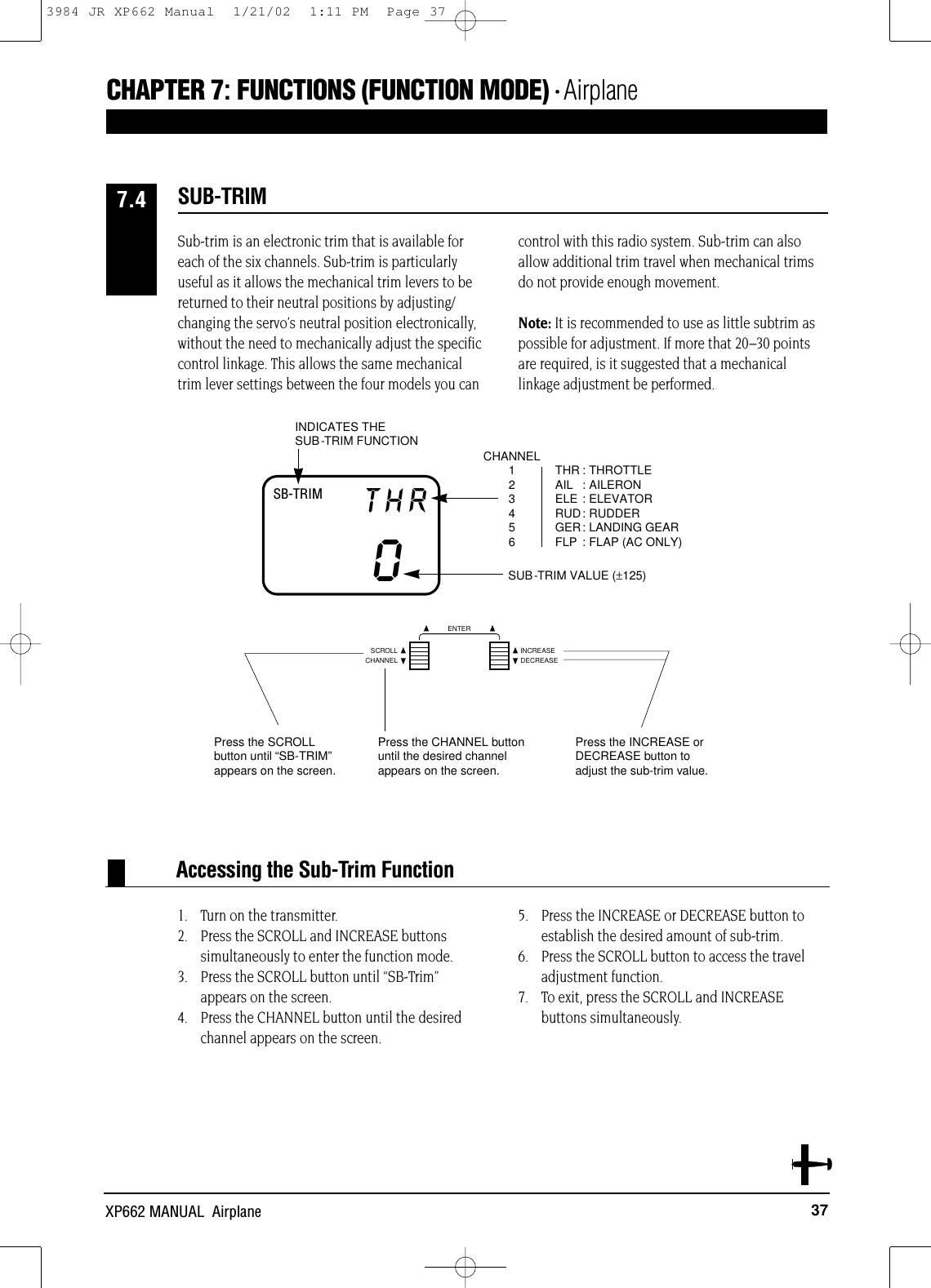
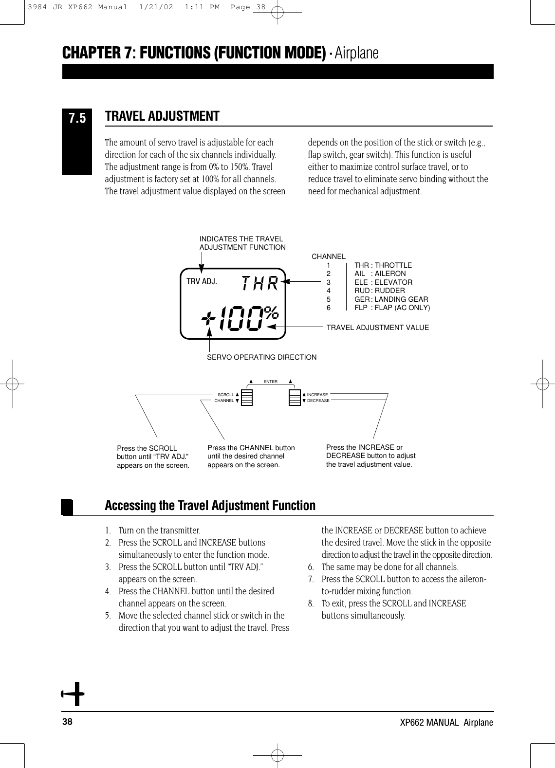
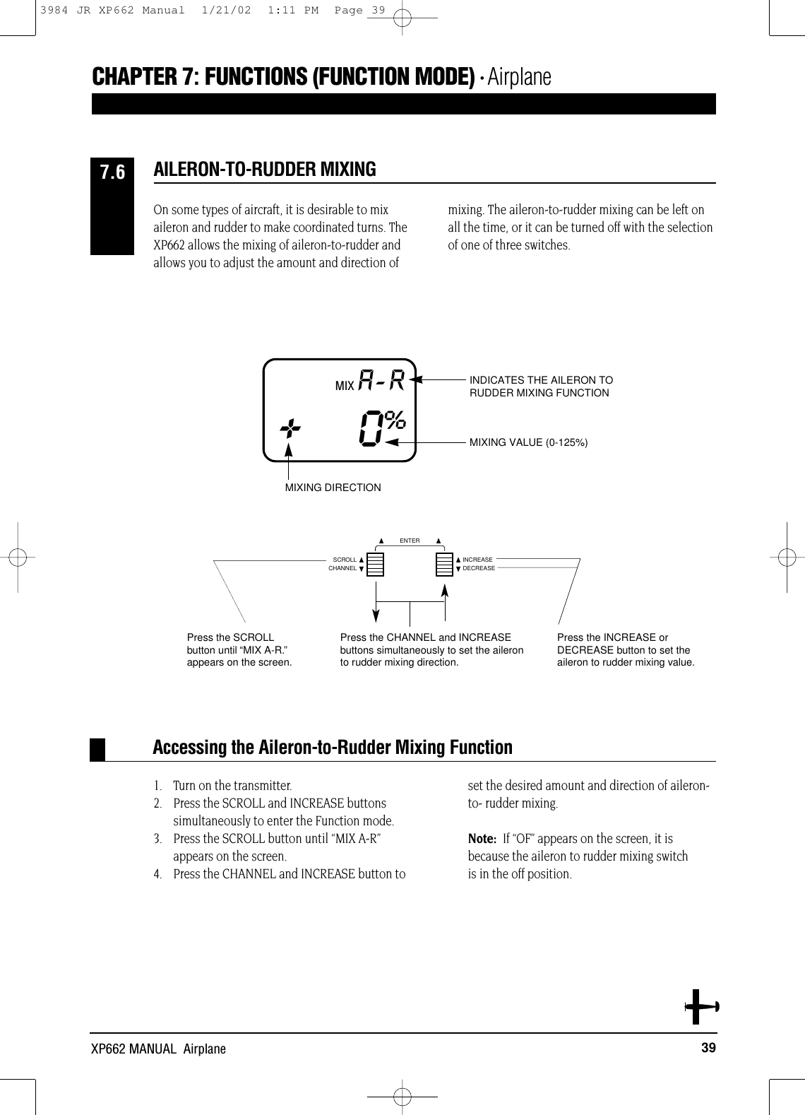
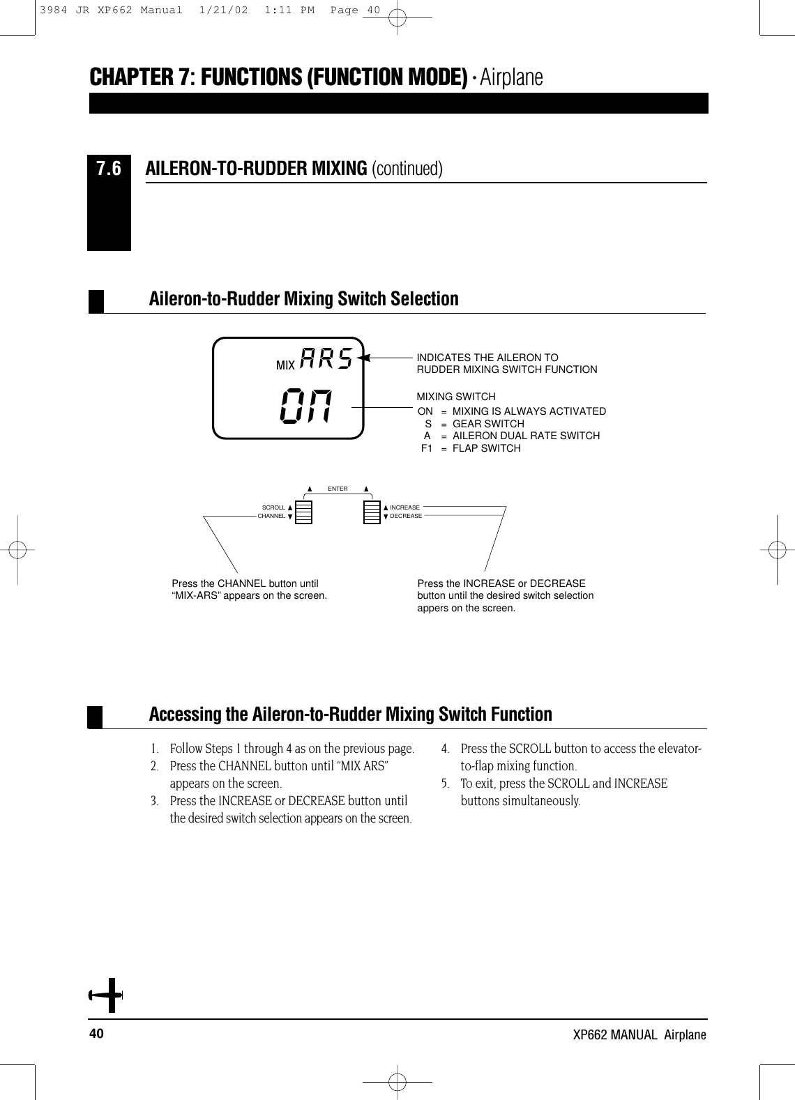
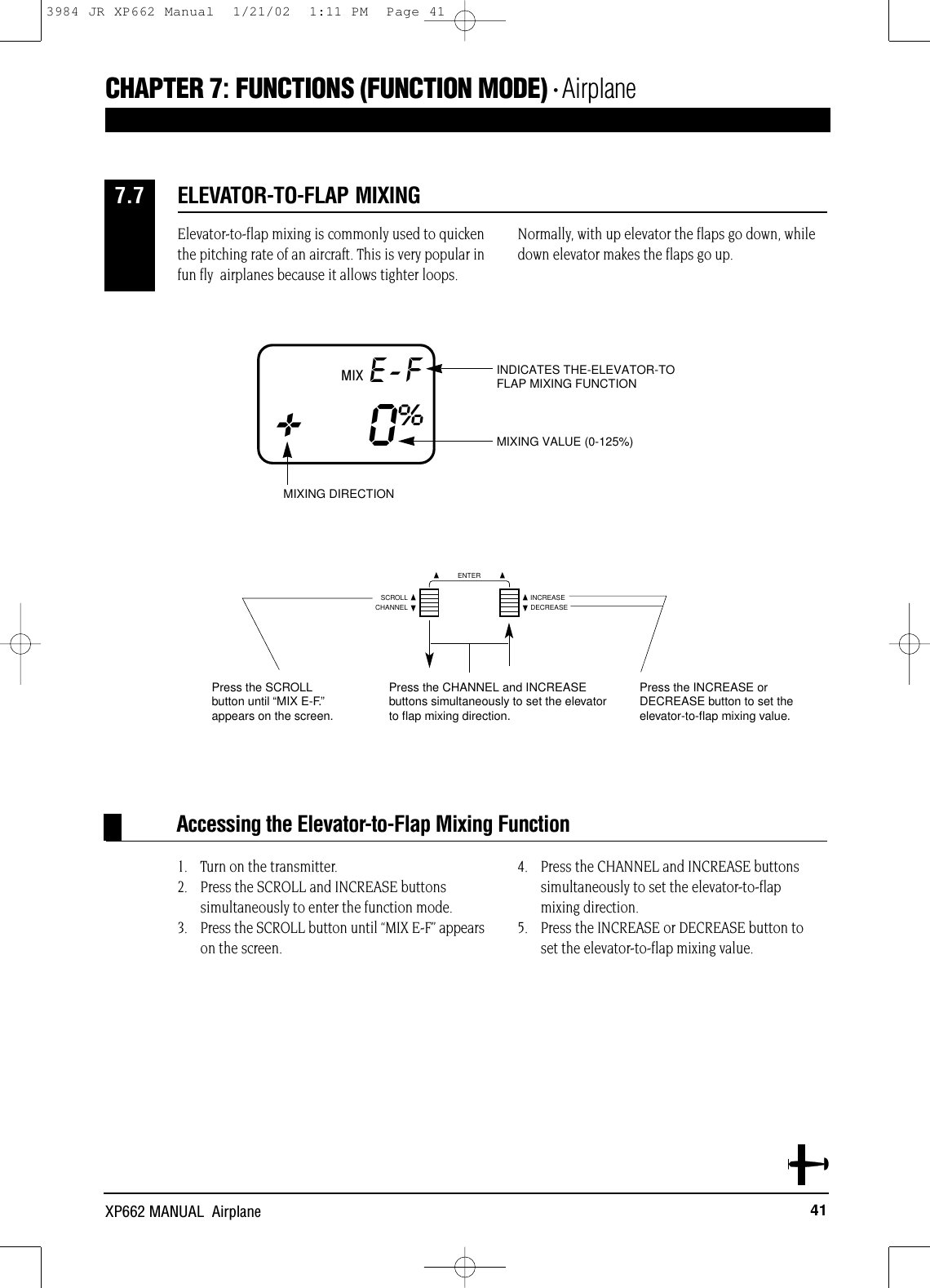
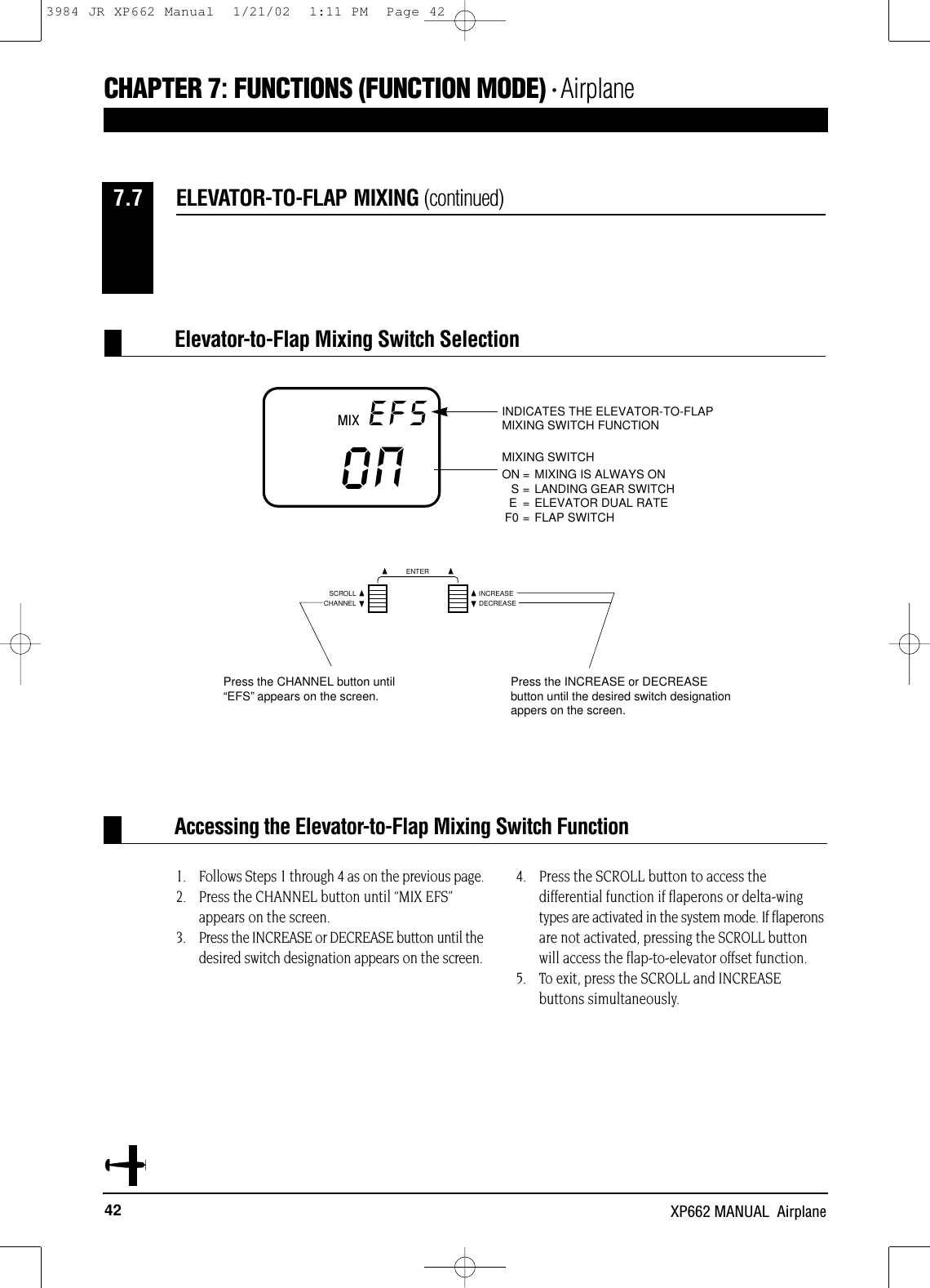
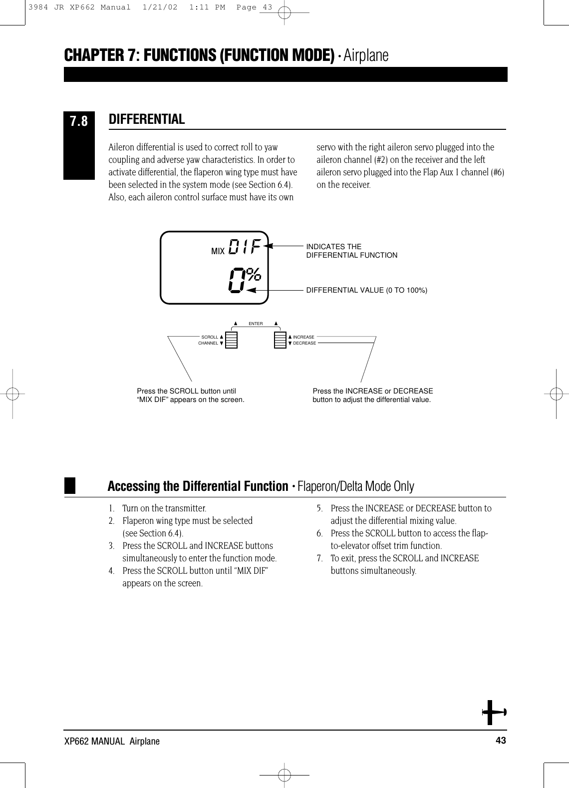
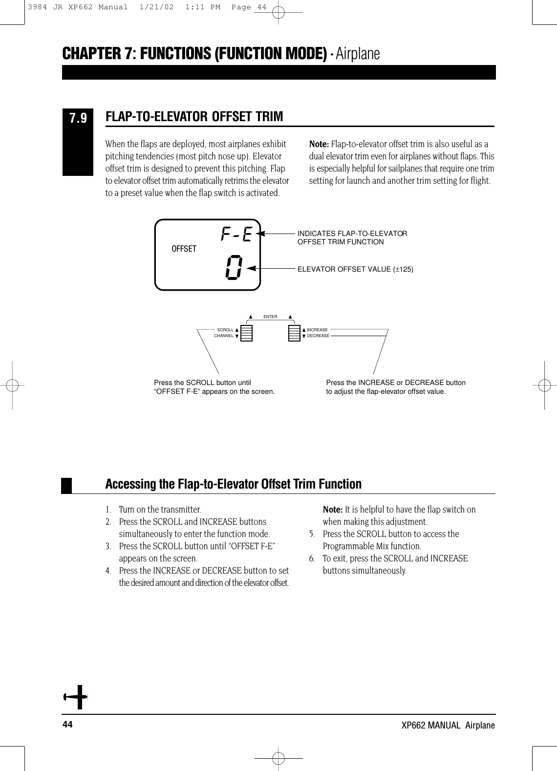
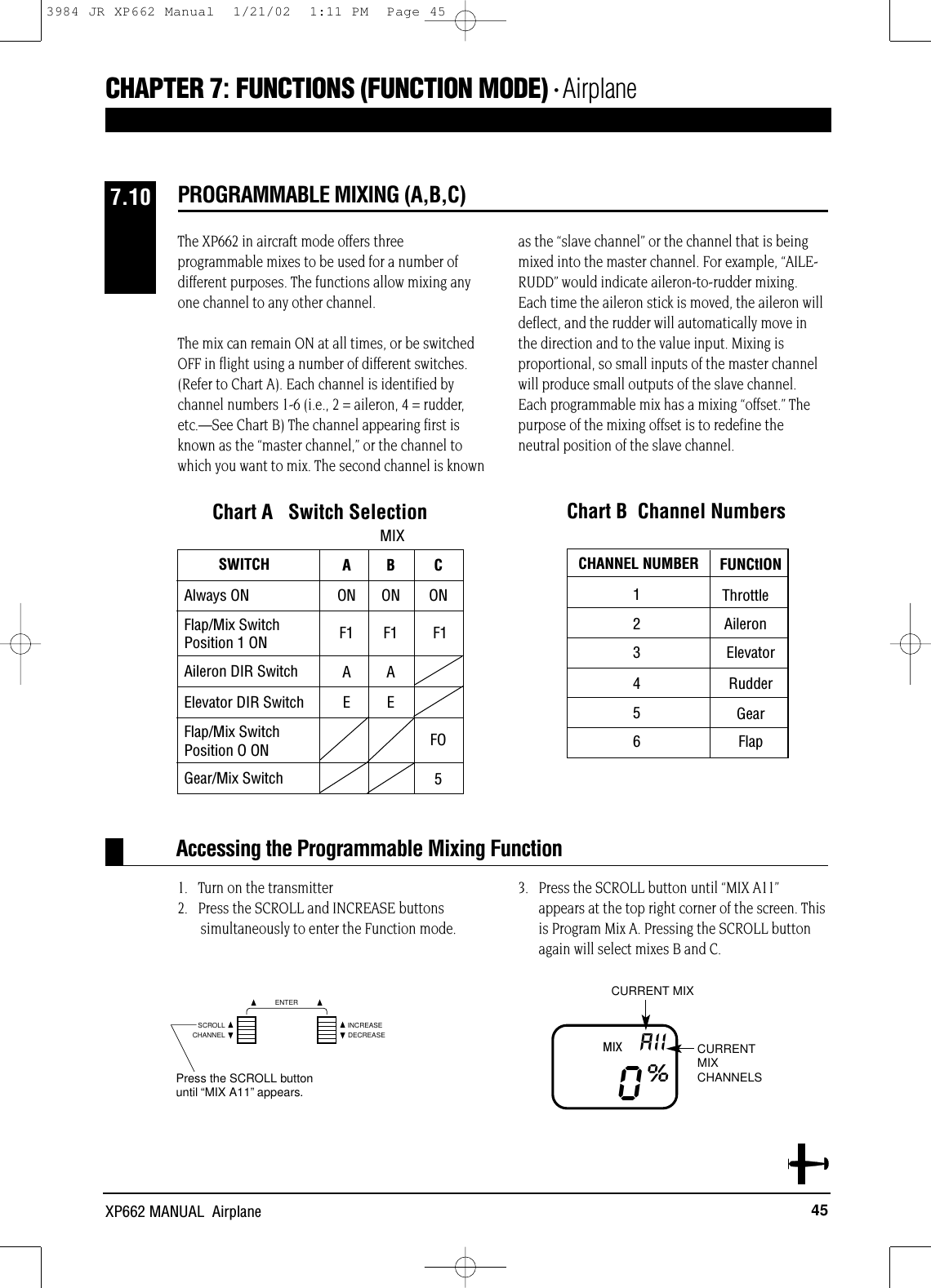
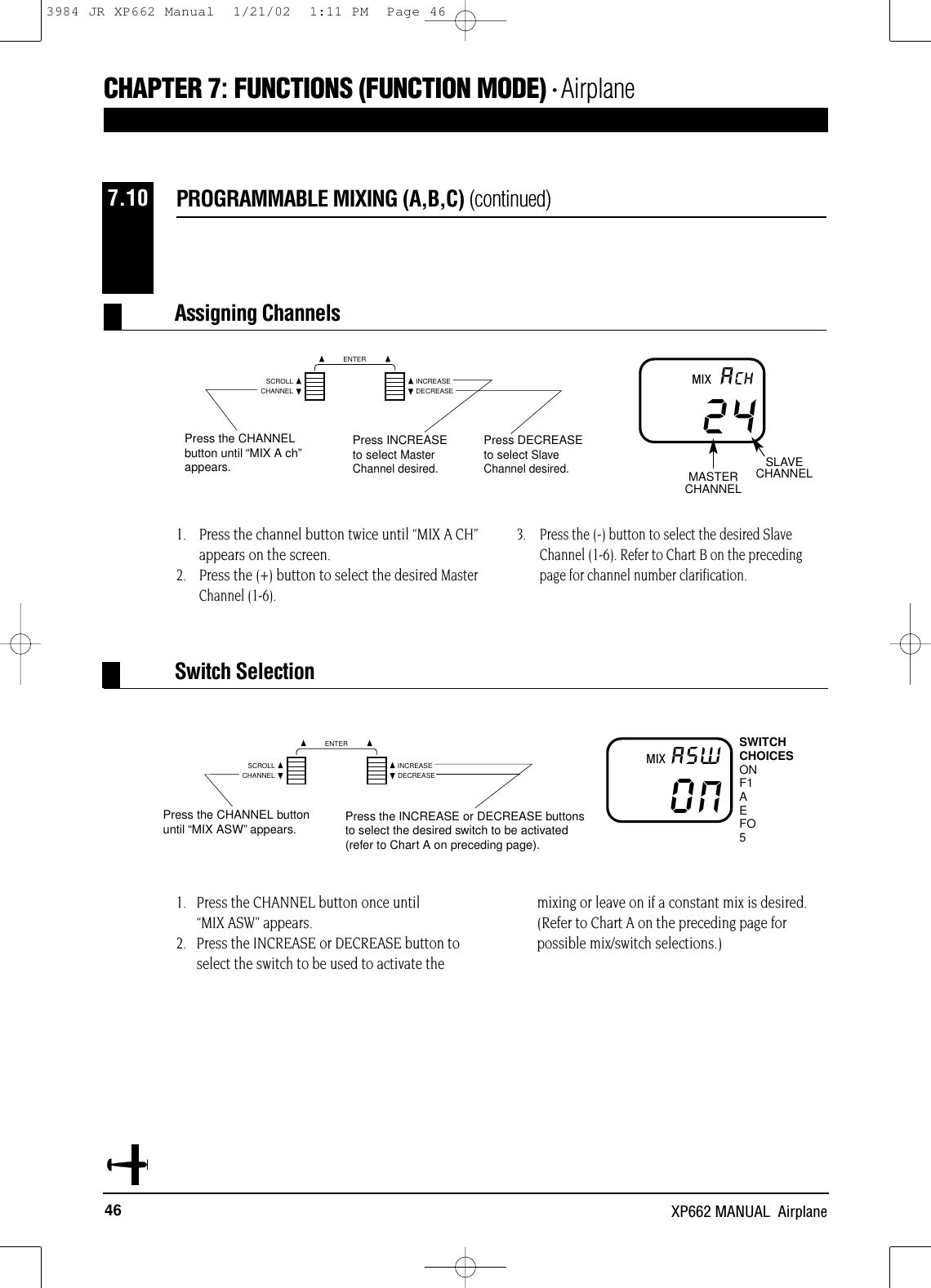
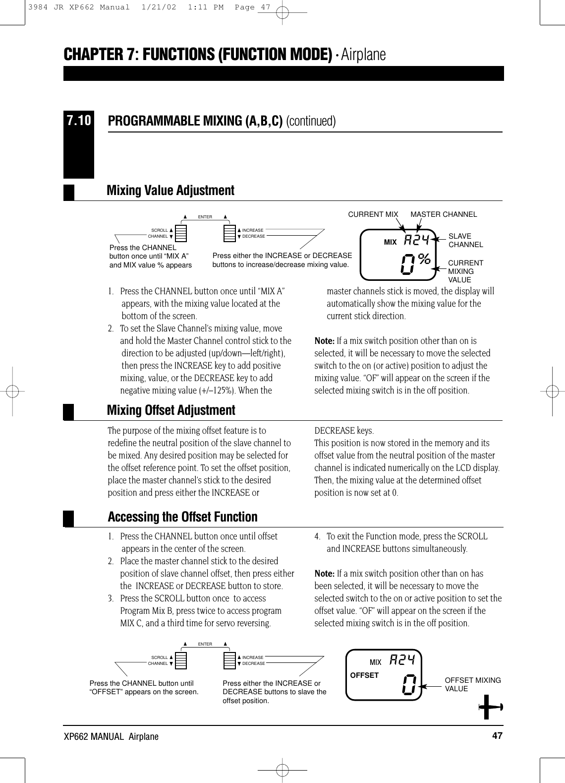
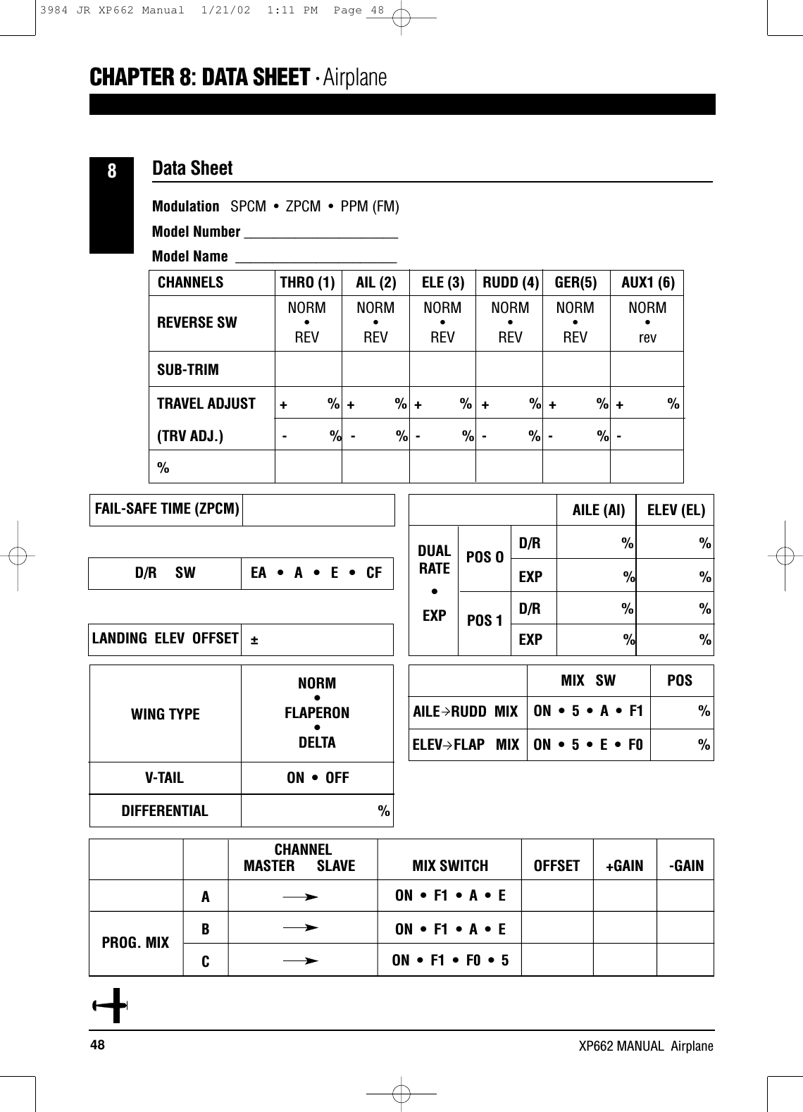
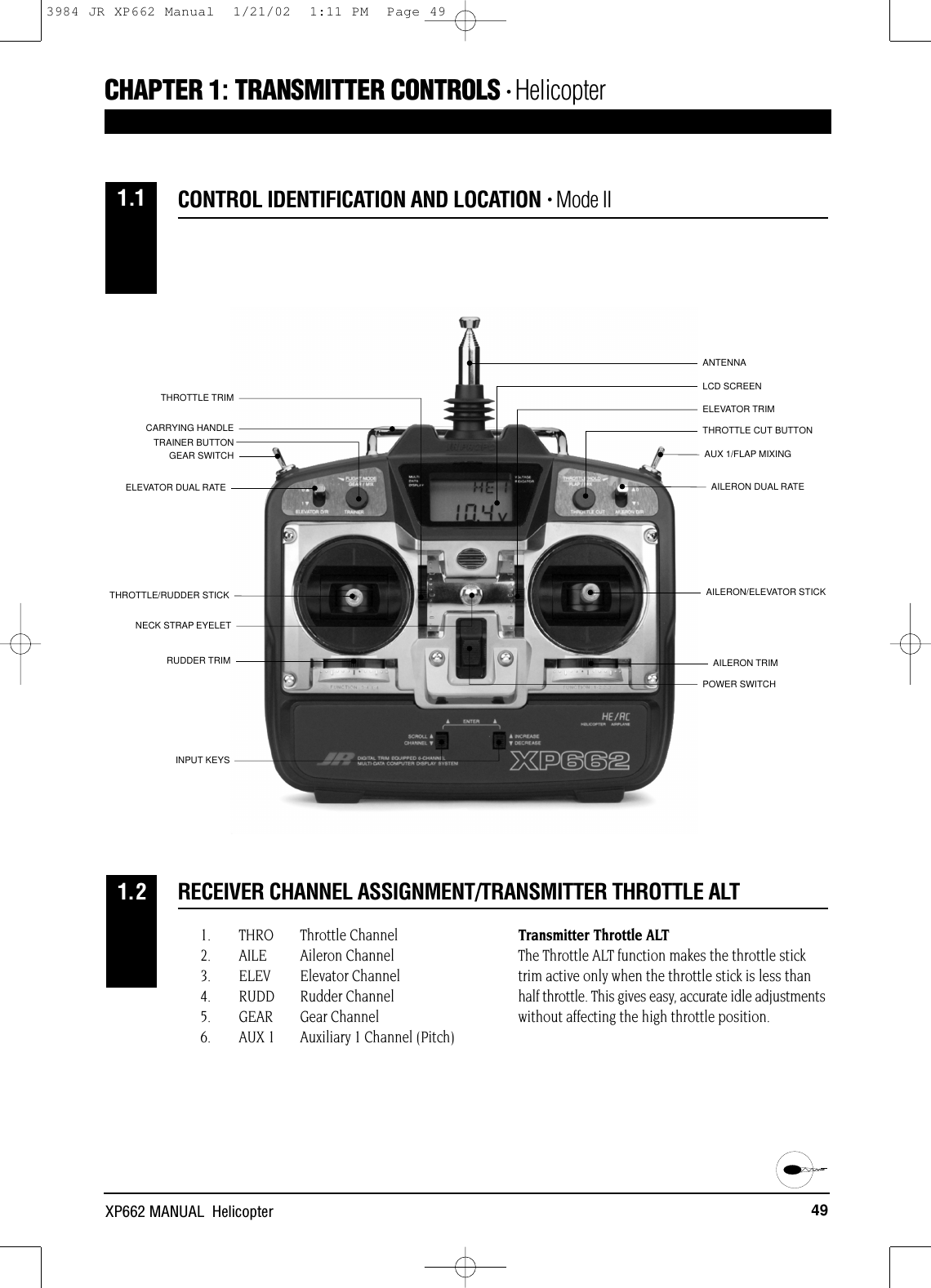
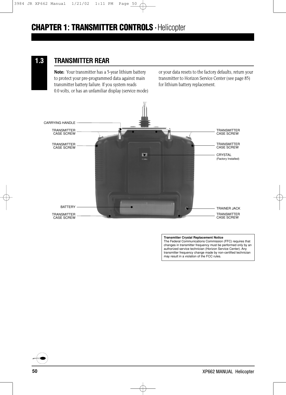
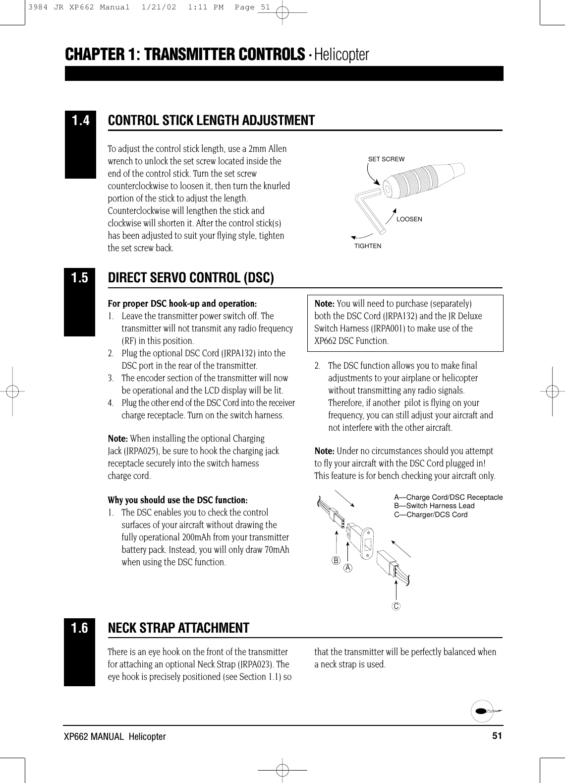
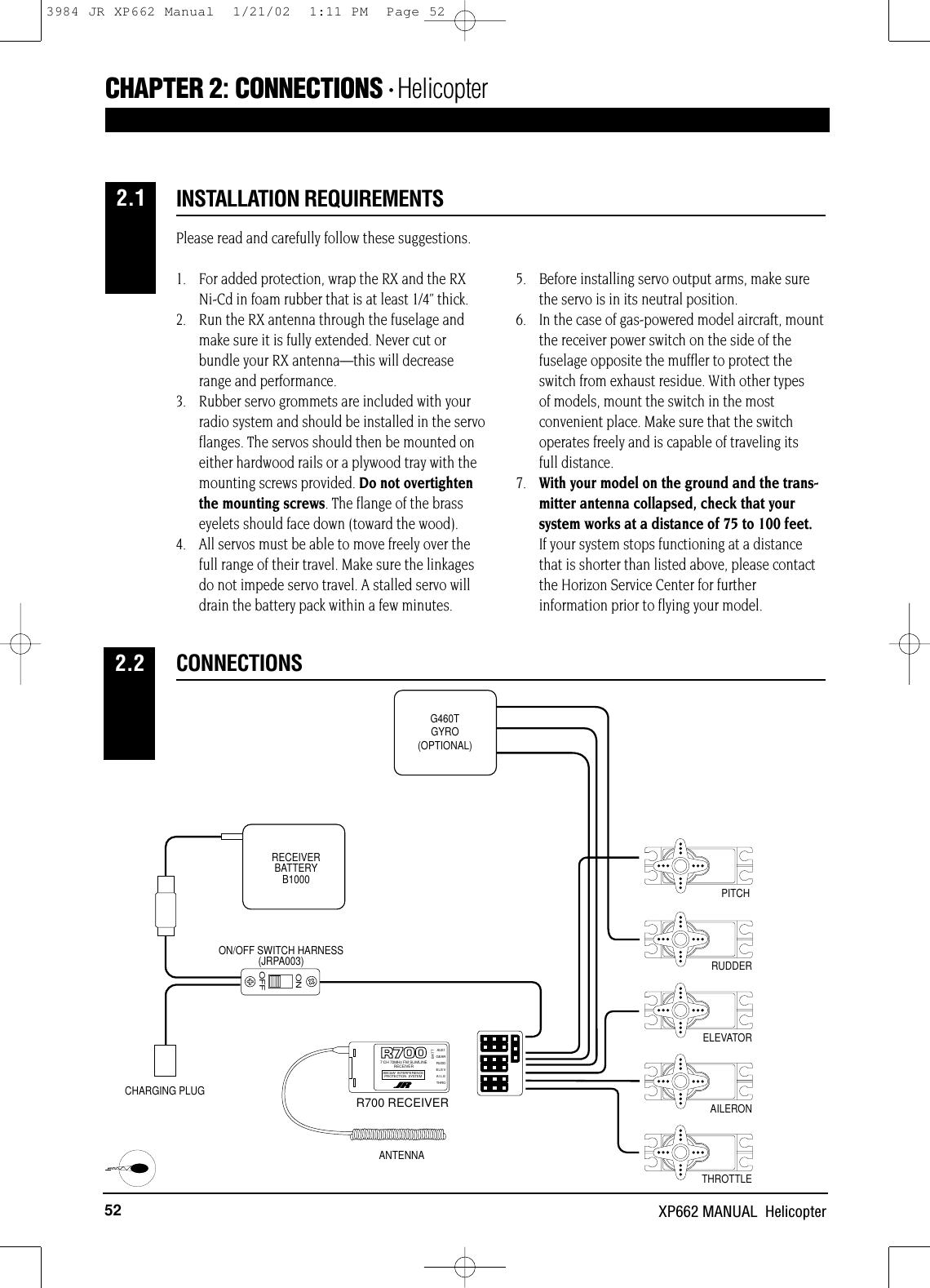
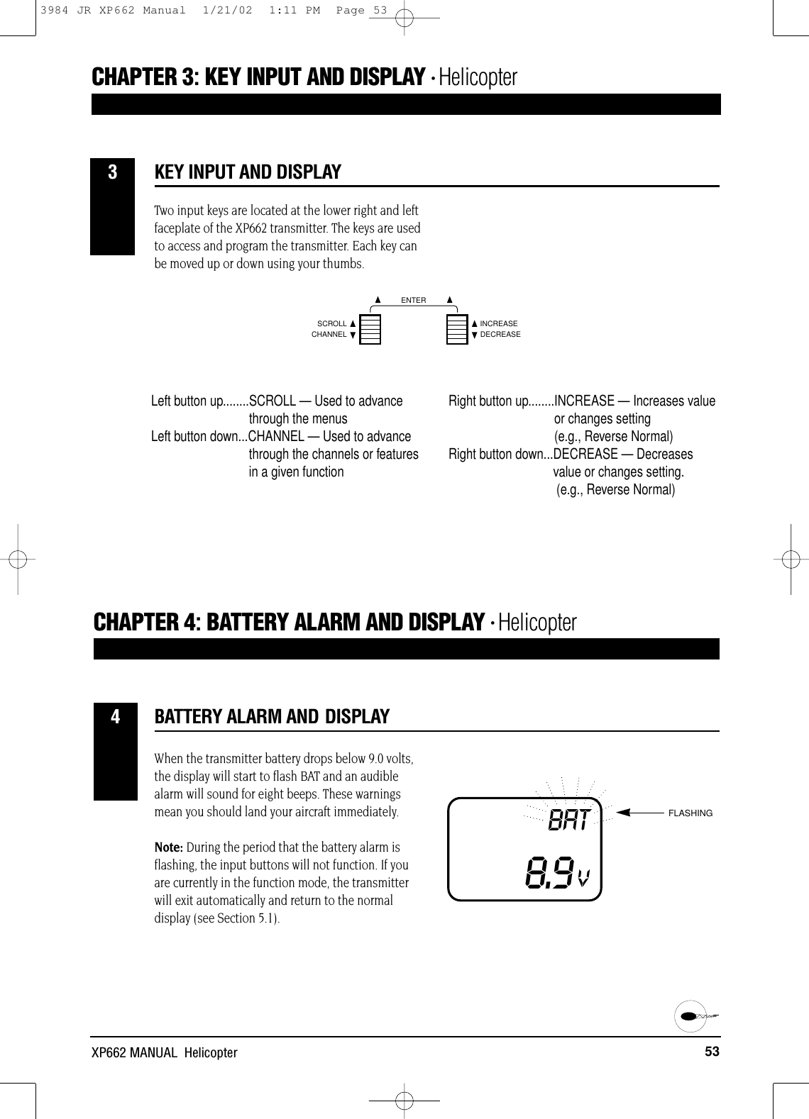
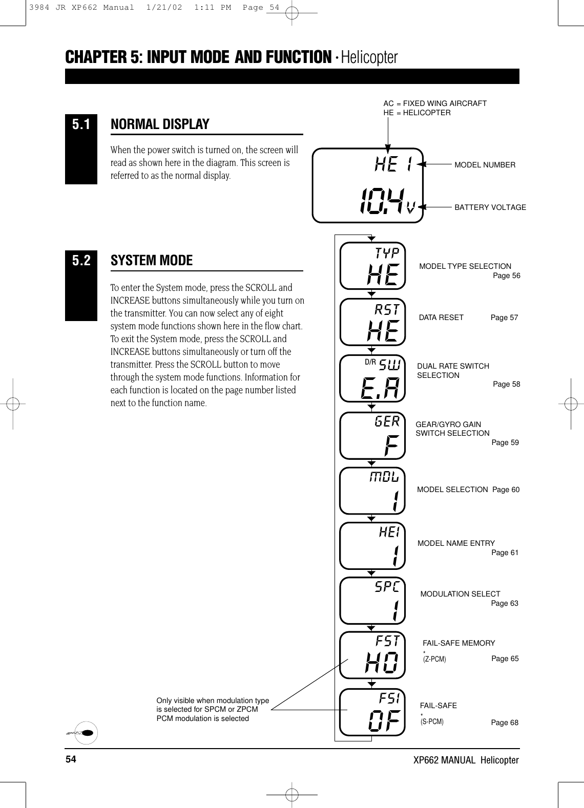
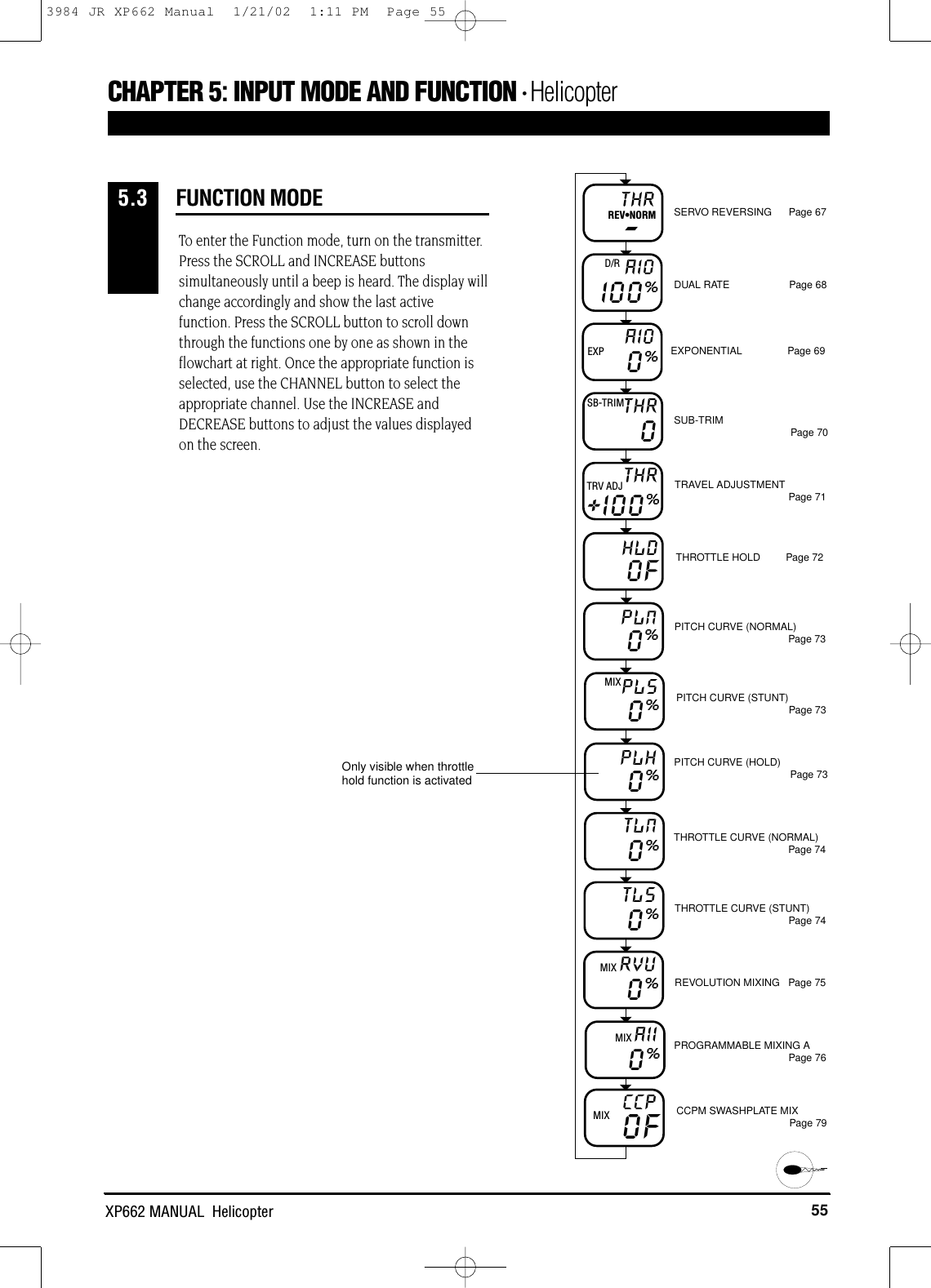
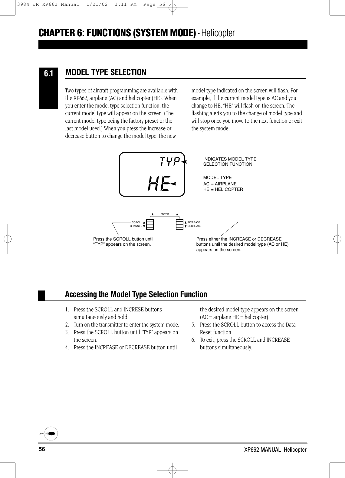
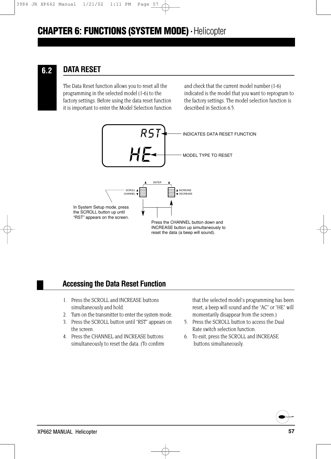
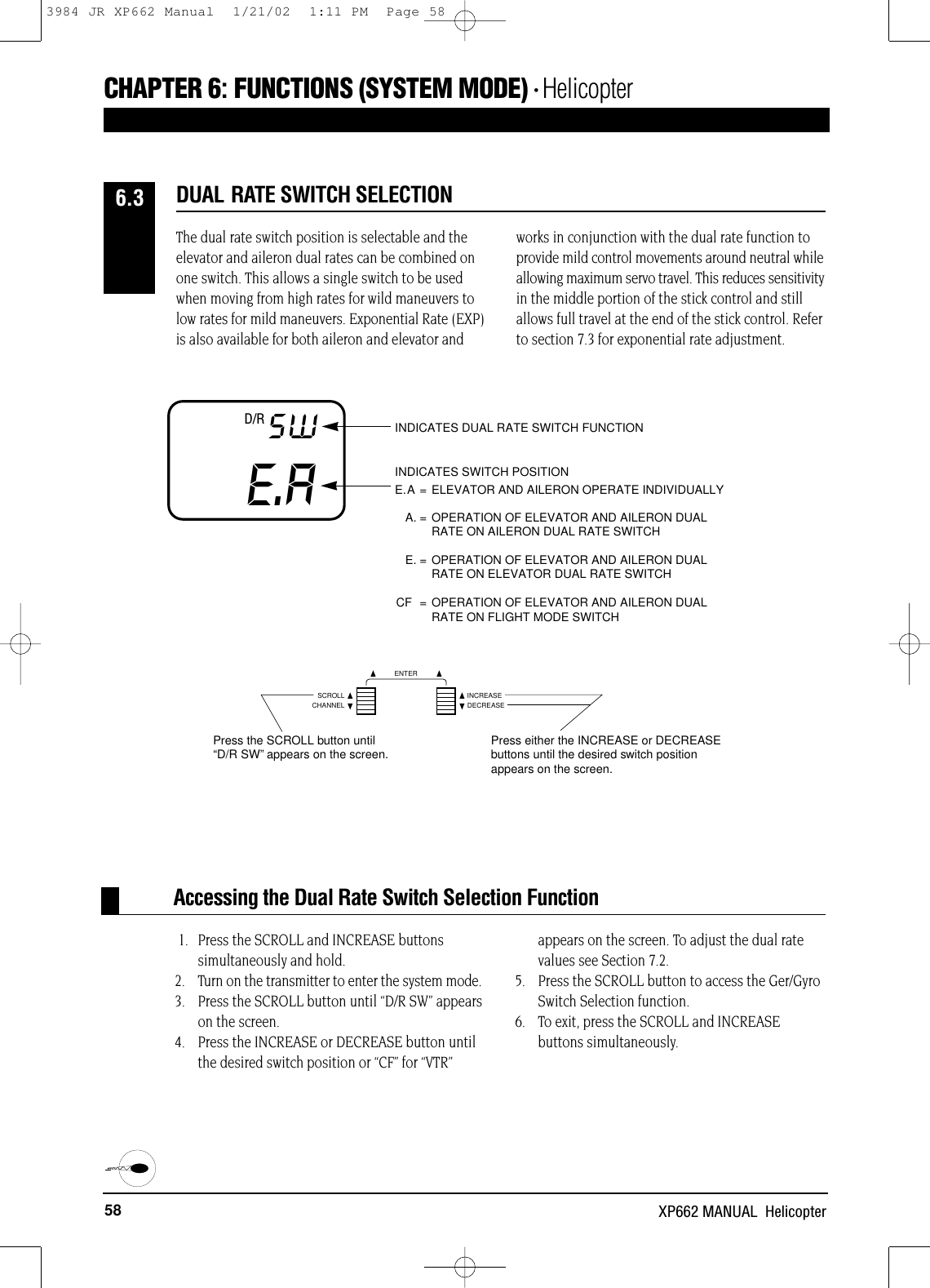
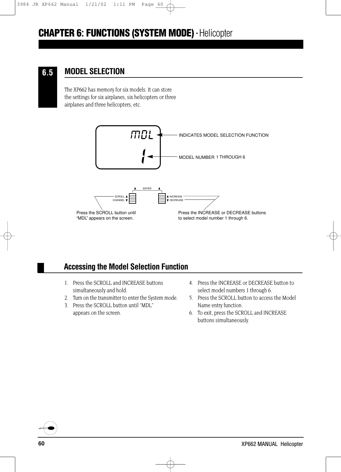
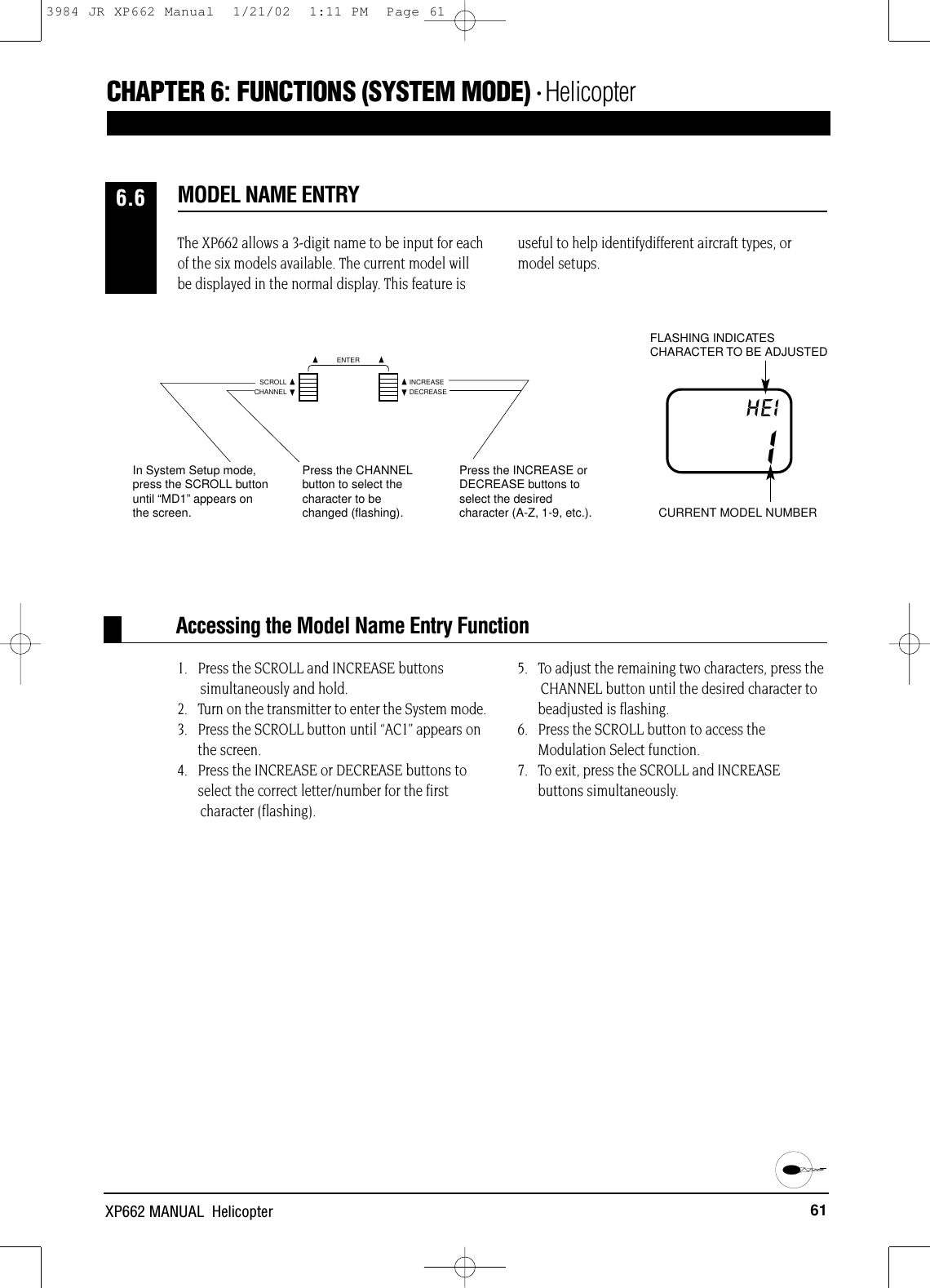
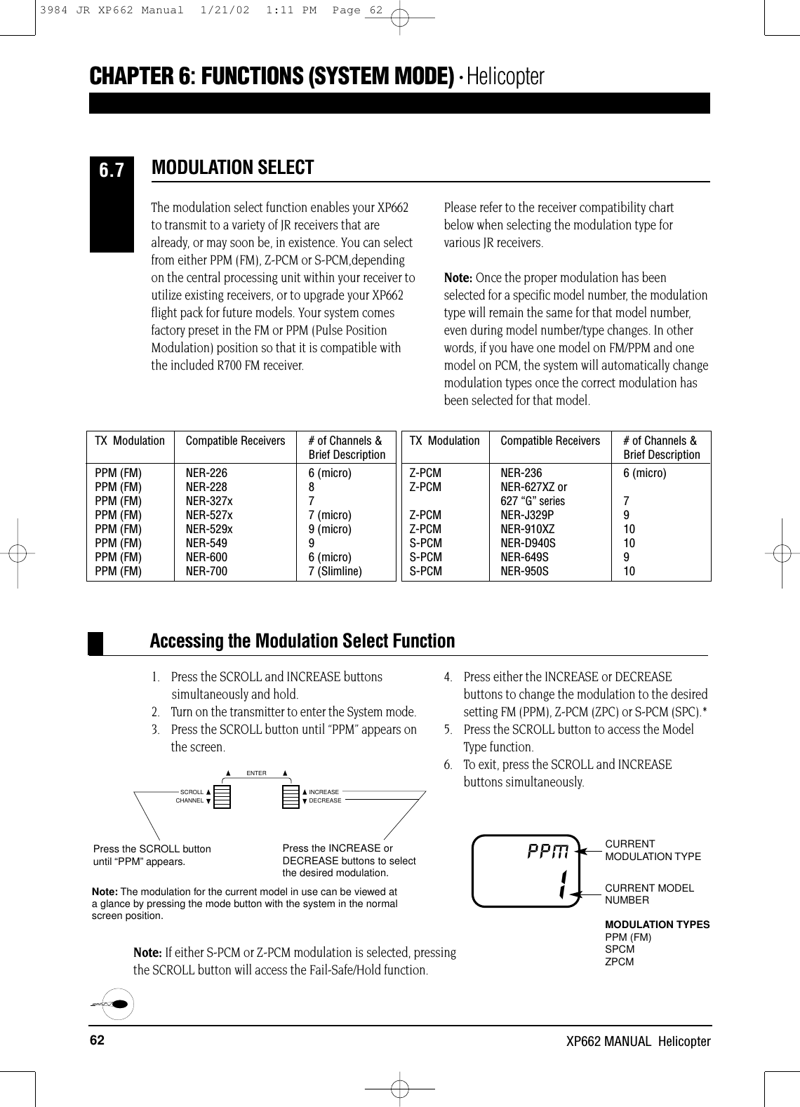
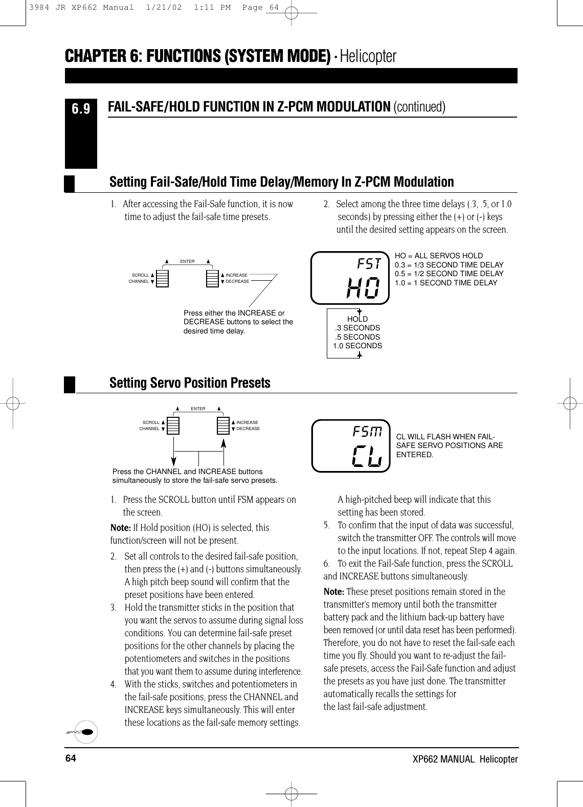
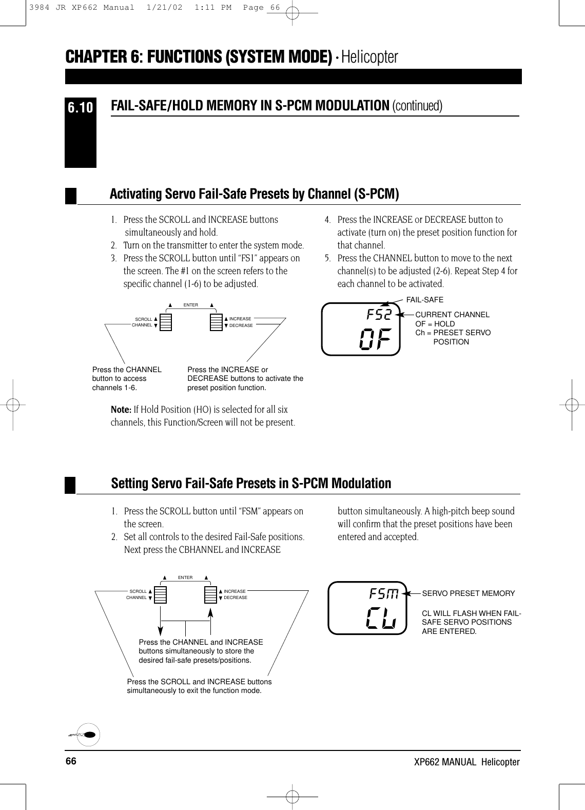
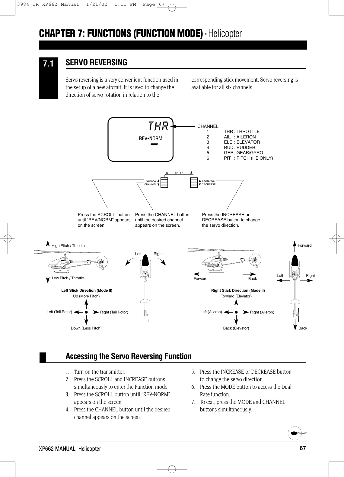
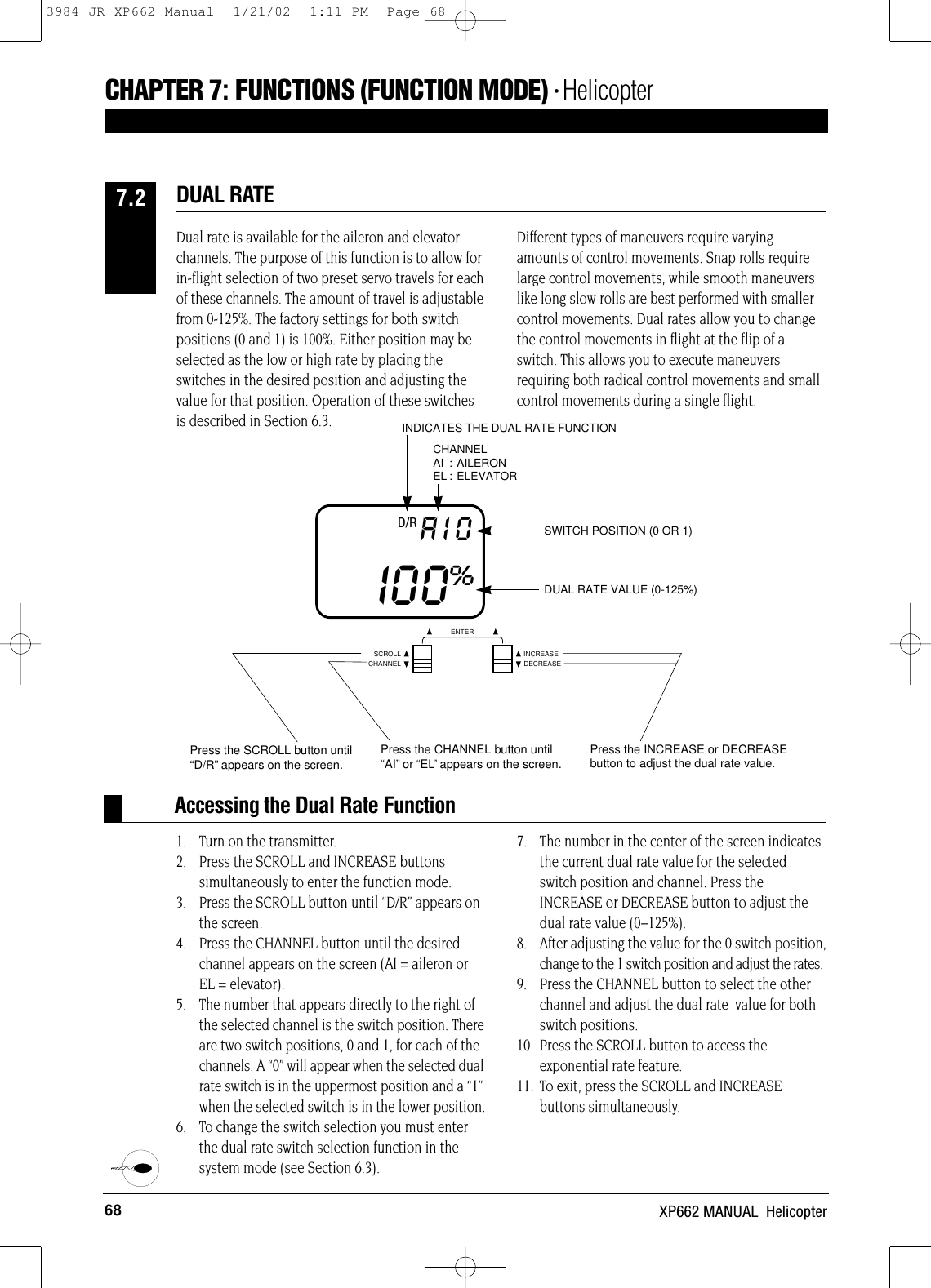
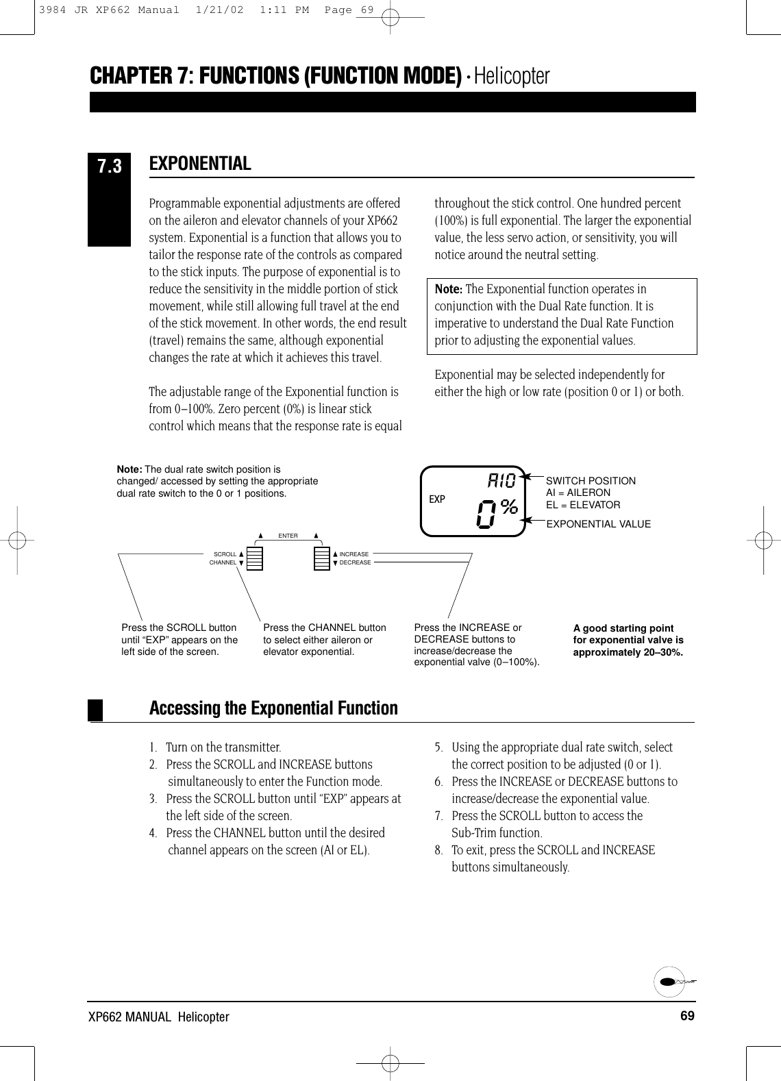
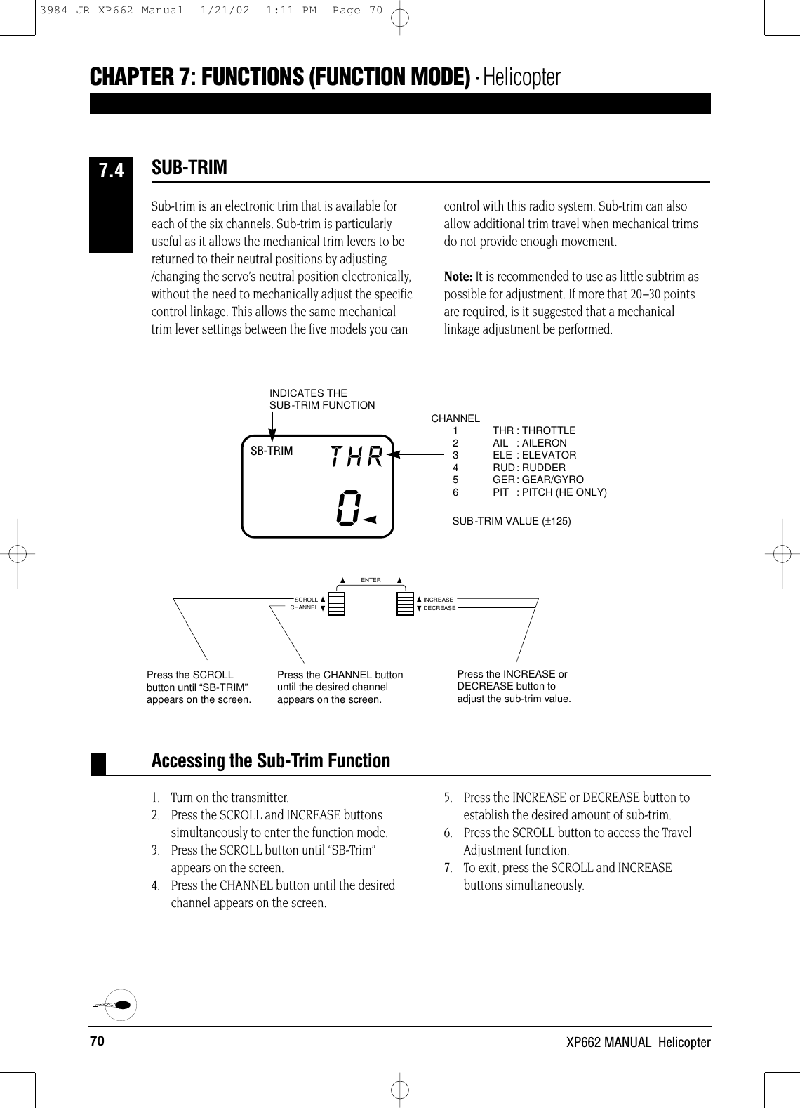
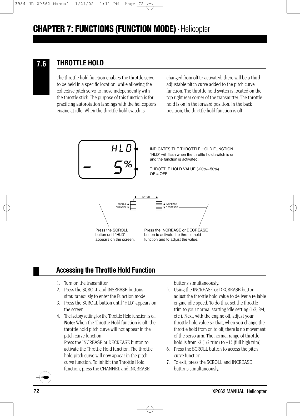
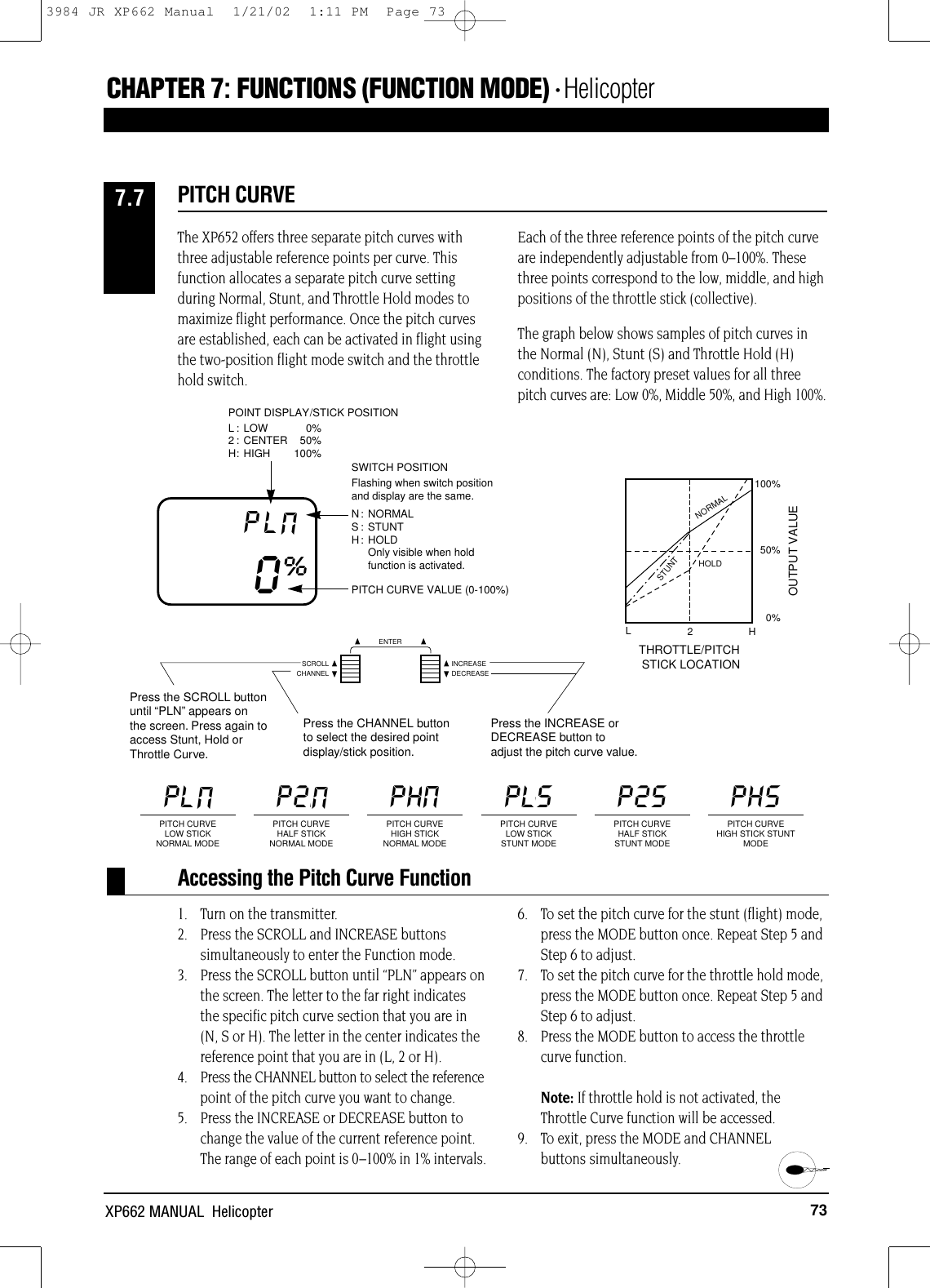
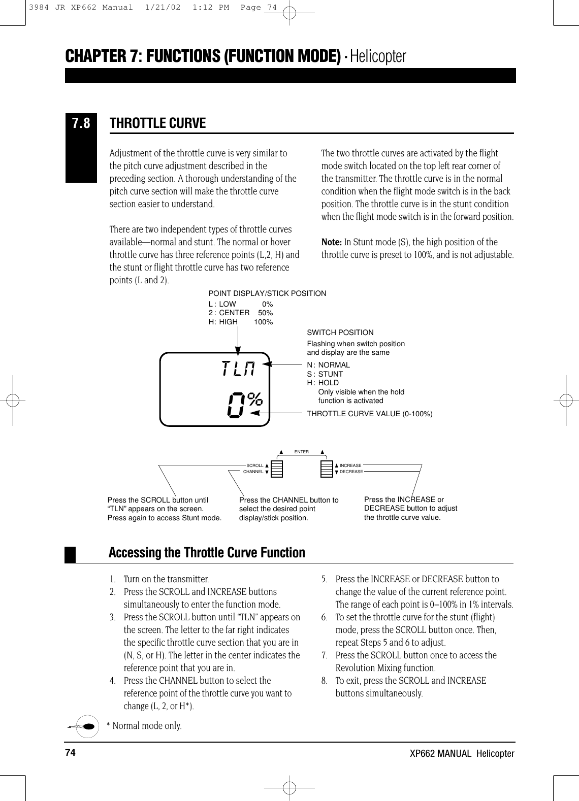
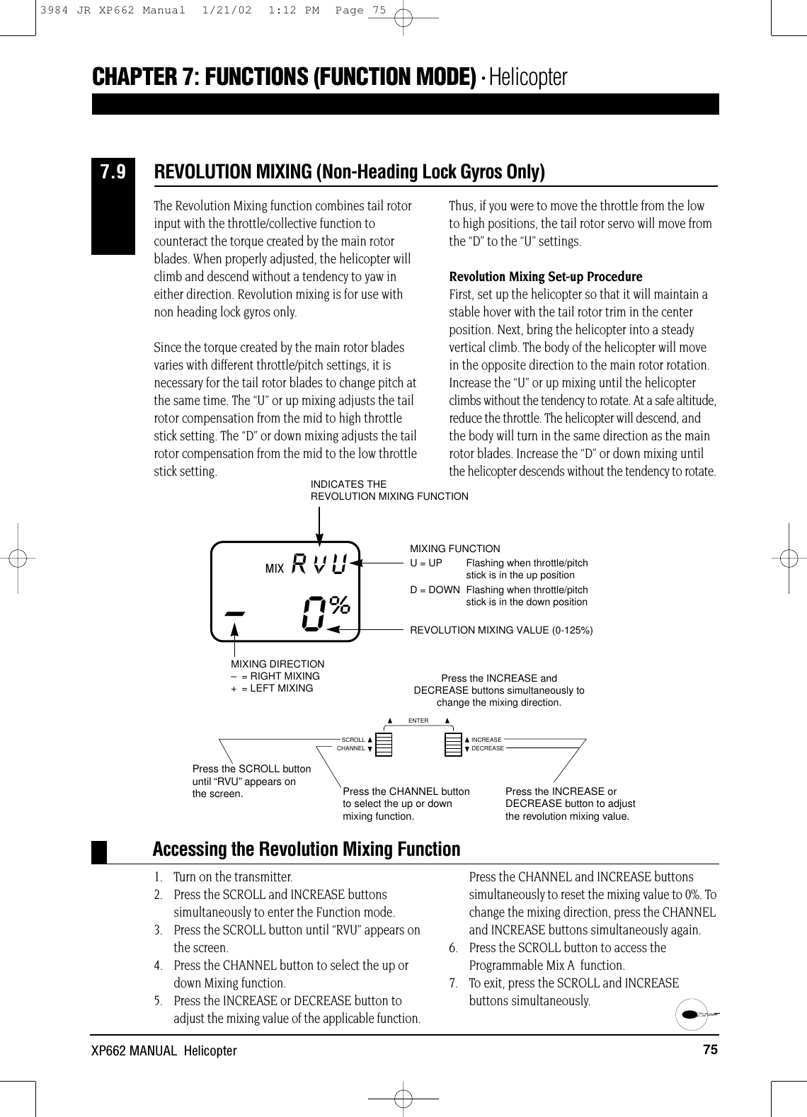
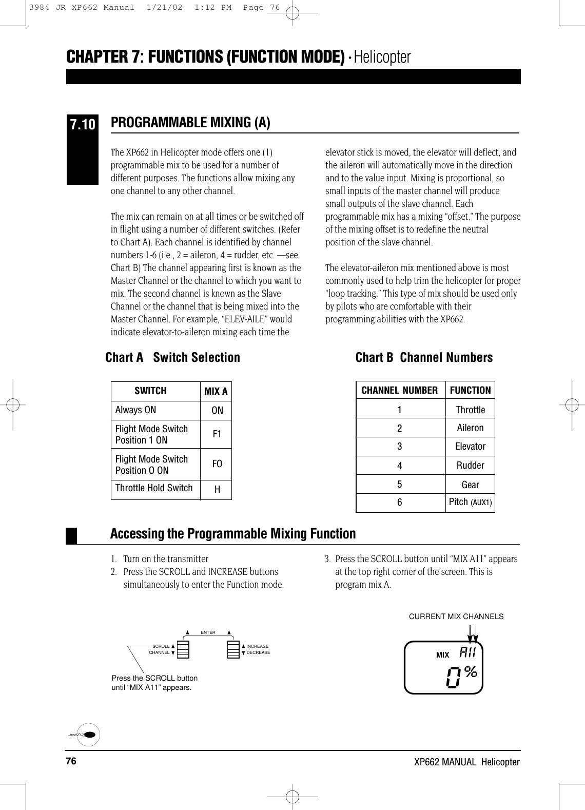
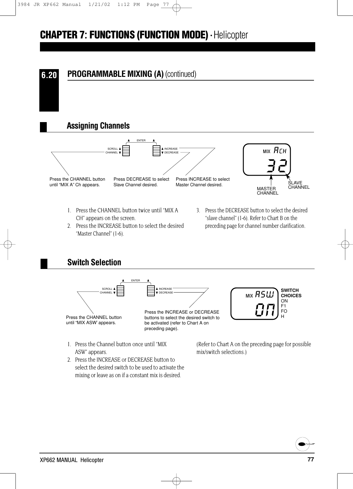
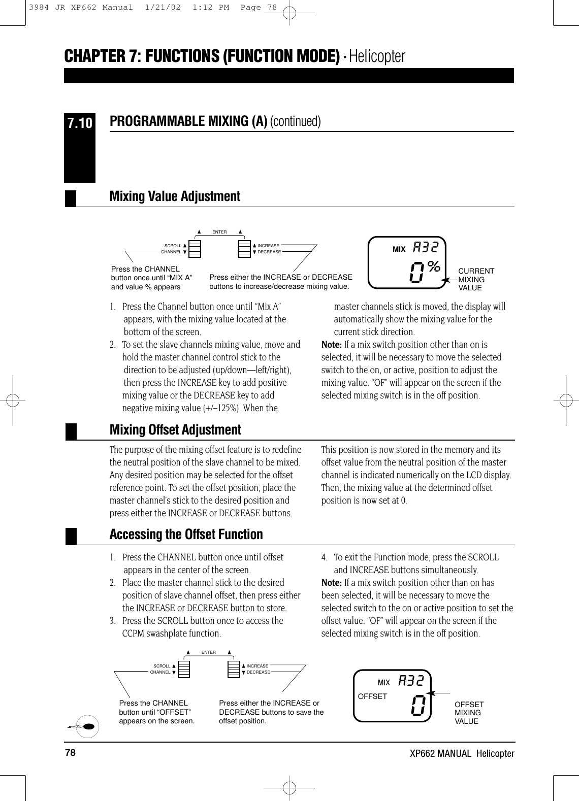
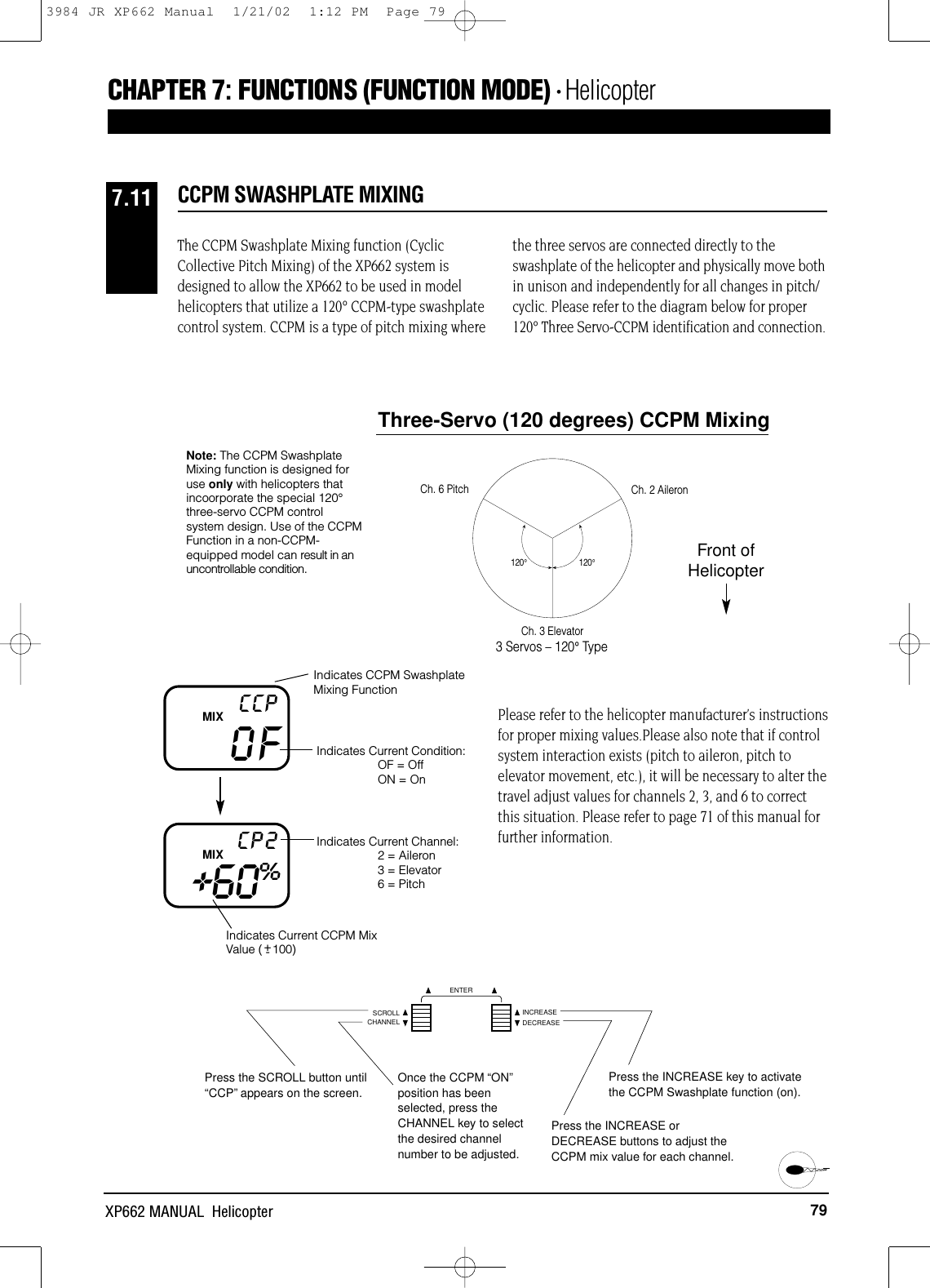
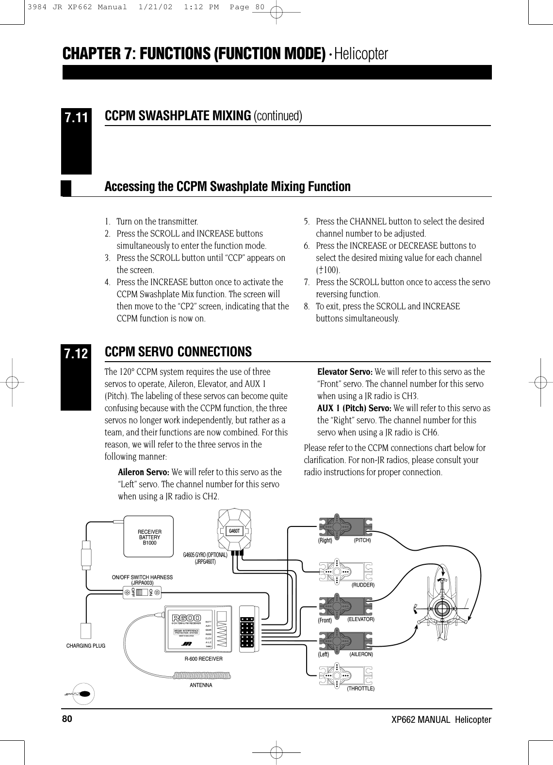
XP662 Manual
Navigation menu
Upload a User Manual
Namespaces
Wiki Guide
HTML
PDF
Info
Views
User Manual
Discussion / Help
Navigation