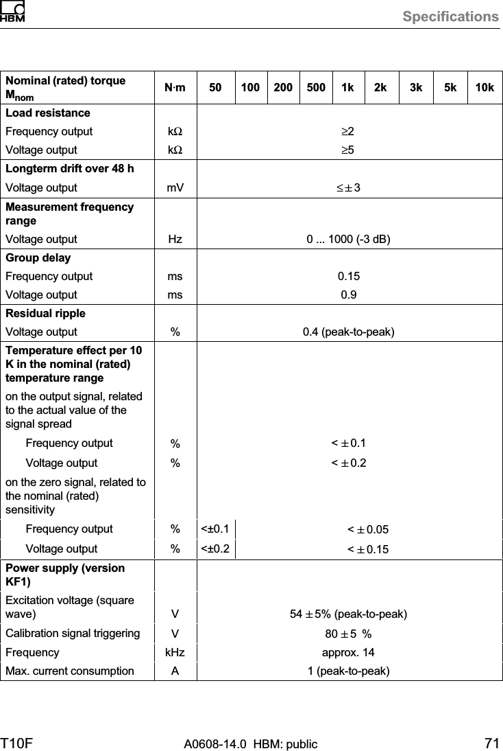
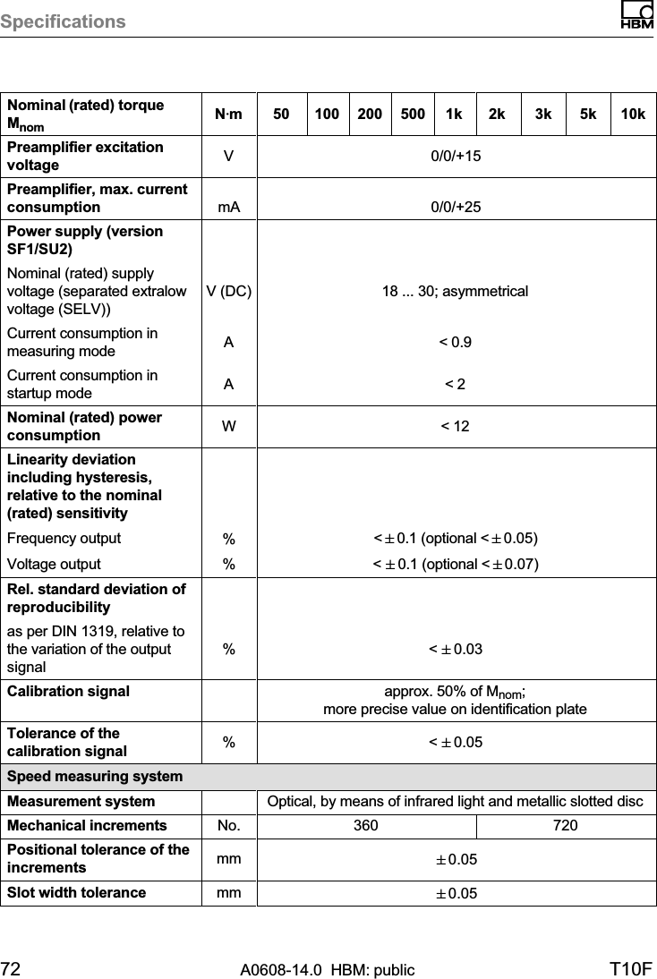
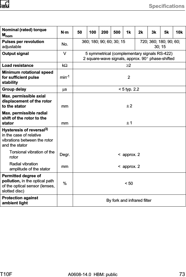
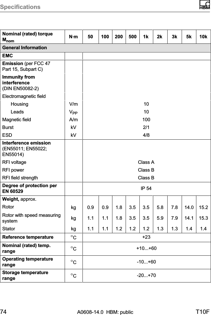
Hottinger Bruel and Kjaer T10S2TOS6 T10-S2TOS6 Torquemeter User Manual A0608 T10F

Hottinger Baldwin Messtechnik GmbH T10-S2TOS6 Torquemeter A0608 T10F

User Manual

Mounting InstructionsEnglishT10F
Hottinger Baldwin Messtechnik GmbHIm Tiefen See 45D-64239 DarmstadtTel. +49 6151 803-0Fax +49 6151 803-9100info@hbm.comwww.hbm.comMat.: 7-2001.1510DVS: A0608-14.0 HBM: public02.2015E Hottinger Baldwin Messtechnik GmbH.Subject to modifications.All product descriptions are for general information only.They are not to be understood as a guarantee of quality ordurability.
T10F A0608-14.0  HBM: public 3English1 Safety instructions 6........................................2 Markings used 11............................................2.1 The markings used in this document 11..........................2.2 Symbols on the product 12.....................................3 Torque flange versions 13....................................4 Application 14...............................................5 Structure and mode of operation 15...........................6 Mechanical installation 17....................................6.1 Conditions on site 19..........................................6.2 Installation orientation 19......................................6.3 Installation options 20.........................................6.3.1 Installation without dismantling the antenna ring 21................6.3.2 Installation with subsequent stator mounting 22...................6.3.3 Installation example with couplings 23...........................6.3.4 Installation example with joint shaft 23...........................6.4 Mounting the rotor 24..........................................6.5 Mounting the stator 28.........................................6.6 Installing the clamp fixture 31...................................6.7 Fitting the slotted disc (speed measuring system) 33..............6.8 Aligning the stator (speed measuring system) 34..................7 Electrical connection 37......................................7.1 General information 37........................................7.1.1 FCC and IC compliant installation for US and Canada installation only 38.....................................7.2 Shielding design 39...........................................7.3 Option 2, code KF1 41........................................7.3.1 Adaptation to the cable length 41...............................
4A0608-14.0  HBM: public T10F7.4 Option 2, code SF1/SU2 43....................................7.5 Supply voltage 46.............................................8 Calibration 48...............................................8.1 Calibration option 2, code KF1 49...............................8.2 Calibration option 2, code SF1/SU2 49...........................9 Settings 50..................................................9.1 Torque output signal, code KF1 51..............................9.2 Torque output signal, code SF1/SU2 51.........................9.3 Setting up the zero point 51....................................9.4 Functional testing 52..........................................9.4.1 Power transmission 52........................................9.4.2 Aligning the speed module 53..................................9.5 Setting the pulse count 55.....................................9.6 Vibration suppression (hysteresis) 56............................9.7 Form of speed output signal 56.................................9.8 Type of speed output signal 58.................................10 Loading capacity 59.........................................10.1 Measuring dynamic torque 59..................................11 Maintenance 61..............................................11.1 Speed module maintenance 61.................................12 Dimensions 62..............................................12.1 Rotor dimensions 62..........................................12.2 Stator dimensions 64..........................................12.3 Mounting dimensions 66.......................................
T10F A0608-14.0  HBM: public 513 Order numbers, accessories 68...............................14 Specifications 70............................................15 Supplementary technical information 78......................15.1 Output signals 78.............................................15.1.1 Output MD torque (connector 1) 78..............................15.1.2 Output N: Speed (connector 2) 79...............................15.1.3 Connector 2, double frequency, stat. direction of rotation signal 80..15.2 Axial and radial run‐out tolerances 81............................15.3 Additional mechanical data 82..................................
Safety instructions6A0608-14.0  HBM: public T10F1 Safety instructionsFCC Compliance & Advisory StatementImportantAny changes or modification not expressly approved bythe party responsible for compliance could void the user'sauthority to operate the device. Where specified additional components or accessories elsewhere defined tobe used with the installation of the product, they must beused in order to ensure compliance with FCC regulations.This device complies with Part 15 of the FCC Rules.Operation is subject to the following two conditions: (1)this device may not cause harmful interference, and (2)this device must accept any interference received, including interference that may cause undesired operation.The FCC identifier or the unique identifier, as appropriate, must be displayed on the device.Model Measuring range FCC ID ICT10S2TO650 Nm, 100 Nm, 200 Nm2ADAT-T10S2TOS6 12438A-T10S2TOS6500 Nm, 1 kNm2 kNm, 3 kNm5 kNm10 kNmThe FCC ID number in dependence of measuring range.
Safety instructionsT10F A0608-14.0  HBM: public 7Fig. 1.1 Location of the label on the stator of the deviceThe preferred position of the FCC label is on the typeplate. If this is not possible for reasons of space, thelabel can be found on the rear of the stator housing.Model: 2ADAT-T10S2TOS6FCC ID: 2ADAT-T10S2TOS6IC: 12438AT10S2TOS6This device complies with part 15 of the FCC Rules. Operation issubject to the following two conditions: (1) This device may notcause harmful interference, and (2) this device must accept anyinterference received, including interference that may cause undesired operation.Fig. 1.2 Label example with FCC ID and IC numberIndustry Canada ICThis device complies with Industry Canada standardRSS210.This device complies with Industry Canada license-exempt RSS standard(s). Operation is subject to the following two conditions: (1) this device may not cause interference, and (2) this device must accept any interference,including interference that may cause undesired operation of the device.
Safety instructions8A0608-14.0  HBM: public T10FCet appareil est conforme aux normes d'exemption delicence RSS d'Industry Canada. Son fonctionnement estsoumis aux deux conditions suivantes : (1) cet appareilne doit pas causer d'interférence et (2) cet appareil doitaccepter toute interférence, notamment les interférencesqui peuvent affecter son fonctionnement.ImportantUsage/Installation in the USA and Canada requires anEMI suppressor. Please refer to chapter 7.1.1, page 38.Designated useThe T10F torque flange is used exclusively for torqueand rotation speed measurement tasks, and directlyassociated control and regulatory tasks. Use for anyadditional purpose shall be deemed to be not asintended.In the interests of safety, the transducer should only beoperated as described in the Operating Manual. It is alsoessential to comply with the legal and safetyrequirements for the application concerned during use.The same applies to the use of accessories.The transducer is not a safety element within themeaning of its designated use. Proper and safe operationof this transducer requires proper transportation, correctstorage, assembly and mounting, and careful operation.General dangers of failing to follow the safetyinstructionsThe transducer corresponds to the state of the art and isfailsafe. The transducer can give rise to remainingdangers if it is inappropriately installed and operated byuntrained personnel.
Safety instructionsT10F A0608-14.0  HBM: public 9Everyone involved with mounting, starting up,maintaining, or repairing the transducer must have readand understood the Operating Manual and in particularthe technical safety instructions.Residual dangersThe scope of supply and performance of the transducercovers only a small area of torque measurementtechnology. In addition, equipment planners, installersand operators should plan, implement and respond to thesafety engineering considerations of torquemeasurement technology in such a way as to minimizeremaining dangers. On‐site regulations must be compliedwith at all times. Reference must be made to remainingdangers connected with torque measurementtechnology. Conversions and modificationsThe transducer must not be modified from the design orsafety engineering point of view except with our expressagreement. Any modification shall exclude all liability onour part for any damage resulting therefrom.Qualified personnelThe transducer must only be installed and used byqualified personnel, strictly in accordance with thespecifications and with safety requirements andregulations. It is also essential to comply with the legaland safety requirements for the application concernedduring use. The same applies to the use of accessories.Qualified personnel means persons entrusted with siting,mounting, starting up and operating the product whopossess the appropriate qualifications for their function.
Safety instructions10 A0608-14.0  HBM: public T10FAccident preventionAccording to the prevailing accident preventionregulations, once the torque flange has been mounted, acovering agent or cladding has to be fitted as follows:SThe cover or cladding must not be free to rotate.SThe cover or cladding should avoid squeezing orshearing and provide protection against parts thatmight come loose.SCovers and cladding must be positioned at a suitabledistance or be arranged so that there is no access toany moving parts within.SCovers and cladding must also be attached if themoving parts of the torque flange are installed outsidepeoples' movement and operating range.The only permitted exceptions to the above requirementsare if the various parts and assemblies of the machineare already fully protected by the design of the machineor by existing safety precautions.WarrantyIn the case of complaints, a warranty can only be given ifthe torque flange is returned in the original packaging.
Markings usedT10F A0608-14.0  HBM: public 112 Markings used2.1 The markings used in this documentImportant instructions for your safety are specificallyidentified. It is essential to follow these instructions inorder to prevent accidents and damage to property.Symbol SignificanceWARNING This marking warns of a potentially dangeroussituation in which failure to comply with safetyrequirements can result in death or serious physicalinjury.CAUTION This marking warns of a potentially dangeroussituation in which failure to comply with safetyrequirements can result in slight or moderate physicalinjury.Notice This marking draws your attention to a situation inwhich failure to comply with safety requirements canlead to damage to property.ImportantThis marking draws your attention to importantinformation about the product or about handling theproduct.TipThis marking indicates application tips or otherinformation that is useful to you.InformationThis marking draws your attention to informationabout the product or about handling the product.EmphasisSee…. Italics are used to emphasize and highlight text andreferences to other chapters and external documents.
Markings used12 A0608-14.0  HBM: public T10F2.2 Symbols on the productCE markThe CE mark enables the manufacturer to guarantee thatthe product complies with the requirements of the relevant EC directives (the declaration of conformity is available at http://www.hbm.com/HBMdoc).Label exampleLabel example with Model number, FCC ID and IC number. Location on the stator of the device.Statutory waste disposal markIn accordance with national and local environmentalprotection and material recovery and recyclingregulations, old devices that can no longer be used mustbe disposed of separately and not with normal householdgarbage.If you need more information about waste disposal,please contact your local authorities or the dealer fromwhom you purchased the product.Model: 2ADAT-T10S2TOS6FCC ID: 2ADAT-T10S2TOS6IC: 12438AT10S2TOS6This device complies with part 15 of theFCC Rules. Operation is subject to thefollowing two conditions: (1) This devicemay not cause harmful interference, and(2) this device must accept any interference received, including interference thatmay cause undesired operation.
Torque flange versionsT10F A0608-14.0  HBM: public 133 Torque flange versionsIn the case of option 2 “Electrical configuration", theT10F torque flange exists in versions KF1, SF1 and SU2.The difference between these versions lies in theelectrical inputs and outputs on the stator, the rotors arethe same for all the versions of a measuring range.Alternatively, versions SF1 and SU2 can be equippedwith a speed measuring system.SF1MeasuredquantityTypeEnergy supplyOutput signalCan be connectedto HBMmeasurementelectronicsExcitation voltage54 VPP/14 kHz;square‐waveTorqueKF1ConnectioncableFrequencyFrequencyV1 ... V4Excitation voltagegenerator in HBMelectronicsT10FSU2Supply voltage 18 V to 30 V DCSeparated extra‐low voltage (SELV circuit)Excitation voltage generator in the torque flangeV5, V6, W1, W2Frequency andvoltageTorque and speed (option)Fig. 3.1 T10F versionsYou can find out which version you have from the statoridentification plate. The version is specified in the“T10F-..." number there.Example: T10F-001R-SU2-S-0-V1-Y (see also page 68).
Application14 A0608-14.0  HBM: public T10F4 ApplicationThe T10F torque flanges record static and dynamictorque on stationary or rotating shafts and determine thespeed, specifying the direction of rotation. Test beds canbe extremely compact because of their extremely shortconstruction. They therefore offer a very wide range ofapplications.In addition to conventional test‐bench engineering(engine, roll and transmission test benches), newsolutions are possible for torque measurements partlyintegrated in the machines. Here, you benefit in full fromthe T10F torque flange special characteristics:SExtremely compact construction with themeasurement flange bodySHigh permissible dynamic loadSHigh permissible lateral forces and bending momentsSVery high torsional stiffnessSNo bearings, no slip ringsDesigned to work without bearings, and with contactlessexcitation voltage and measured value transmission, themeasurement flanges are maintenance‐free. Thus thereare no friction or bearings heating effects.The torque flanges are supplied for nominal (rated)torques from 50 N⋅m to 10 kN⋅m. Depending on thenominal (rated) torque, maximum speeds of up to 15 000min-1 are permissible.T10F torque flanges are reliably protected againstelectromagnetic interference. They have been tested withregard to EMC according to the relevant Europeanstandards, and carry the CE mark.
Structure and mode of operationT10F A0608-14.0  HBM: public 155 Structure and mode of operationTorque flanges consist of two separate parts: the rotorand the stator. The rotor comprises the measuring bodyand the signal transmission elements.Strain gauges (SGs) are mounted on the measuringbody. The rotor electronics for transmitting the bridgeexcitation voltage and the measurement signal arelocated centrally in the flange. The transmitter coils forcontactless transmission of excitation voltage andmeasurement signal are located on the measuring body'souter circumference. The signals are sent and receivedby a separable antenna ring. The antenna ring ismounted on a housing that includes the electronicsystem for voltage adaptation and signal conditioning.Connectors for the torque signal, the voltage supply andthe speed signal (option) are located on the stator. Theantenna ring should be mounted more or lessconcentrically around the rotor (see chapter 6).In the case of the speed measuring system option, thespeed sensor is mounted on the stator, the customerattaches the associated slotted disc on the rotor. Thespeed measurement works optically with the infraredtransmitted light barrier principle.
Structure and mode of operation16 A0608-14.0  HBM: public T10FStatorAntenna segmentsRotorFan‐type lockwashersSpeed sensor (option)MeasuringbodyAdapter flange(without slotted disc)HousingFig. 5.1 Mechanical structure, exploded view
Mechanical installationT10F A0608-14.0  HBM: public 176 Mechanical installationWARNINGHandle the torque flange carefully! The transducer couldsuffer permanent damage from mechanical shock(dropping), chemical effects (e.g. acids, solvents) orthermal effects (hot air, steam).With alternating loads, you should cement the rotorconnection screws into the mating thread with a screwlocking device (medium strength) to exclude prestressingloss due to screw slackening.An appropriate shaft flange enables the T10F torqueflanges to be mounted directly. It is also possible tomount a joint shaft or relevant compensating elementdirectly on the rotor (using an intermediate flange whenrequired). Under no circumstances must the permissiblelimits specified for bending moments, lateral andlongitudinal forces be exceeded. Due to the T10F torqueflanges' high torsional stiffness, dynamic changes on theshaft train are minimized.ImportantThe effect on critical bending speeds and naturaltorsional vibrations must be checked to avoid overloadingthe measurement flanges due to the resonance stepup.
Mechanical installation18 A0608-14.0  HBM: public T10FImportantEven if the unit is installed correctly, the zero pointadjustment made at the factory can shift byapprox. ±150 Hz. If this value is exceeded, we adviseyou to check the mounting conditions.ImportantFor correct operation, comply with the mountingdimensions (see page 66).
Mechanical installationT10F A0608-14.0  HBM: public 196.1 Conditions on siteT10F torque flanges are protected to IP54 according toEN 60529. The measuring hubs must be protectedagainst coarse dirt particles, dust, oil, solvents andhumidity. During operation, the prevailing safetyregulations for the security of personnel must beobserved (see chapter 1 „Safety instructions“, page 6).There is wide ranging compensation for the effects oftemperature on the output and zero signals of the T10Ftorque flange (see chapter 14 “Specifications”, page 70).This compensation is carried out at static temperatures inextensive furnace processes. This guarantees that thecircumstances can be reproduced and the properties ofthe transducer can be reconstructed at any time.If there are no static temperature ratios, for example,because of the temperature differences between themeasuring body and the flange, the values given in thespecifications can be exceeded. So, for accuratemeasurements, static temperature conditions must thenbe obtained by cooling or heating depending on theapplication. As an alternative, check thermal decouplingby means of heat radiating elements such as multi‐disccouplings.6.2 Installation orientationThe measurement flange can be mounted in anyposition. With clockwise torque, the output frequency is10 kHz to 15 kHz. With HBM amplifiers or with the“voltage output" option, a positive output signal (0 V ...+10 V) is present.In the case of the speed measuring system, an arrow isattached to the head of the sensor to clearly define the
Mechanical installation20 A0608-14.0  HBM: public T10Fdirection of rotation. If the measurement flange moves inthe direction of the arrow, connected HBM measuringamplifiers deliver a positive output signal (0 V ... +10 V).6.3 Installation optionsIn principle, there are two possibilities for torque flangemounting: with the antenna ring complete or dismantled.We recommend mounting as described in chapter 6.3.1.“Installation without dismantling the antenna ring” Ifinstallation in accordance with chapter 6.3.1 is notpossible, (e.g. in the case of subsequent statorreplacement or mounting with a speed measuringsystem), you will have to dismantle the antenna ring. It isessential in this case to comply with the notes onassembling the antenna segments (see chapter 6.5“Mounting the stator” on page 28 and chapter 6.7“Fitting the slotted disc (speed measuring system)” onpage 33).
Mechanical installationT10F A0608-14.0  HBM: public 216.3.1 Installation without dismantling the antennaring1. Install rotor 2. Install stator3. Finish installation of shaft trainCustomer mountingSupport supplied by customerClamp fixture4. Mount the clamp fixture where required
Mechanical installation22 A0608-14.0  HBM: public T10F6.3.2 Installation with subsequent stator mounting2. Install shaft train3. Remove one antenna segment5. Align stator and finish installation4. Install antenna segment around shaft trainSupport supplied by customerClamp fixture6. Mount the clamp fixture where requiredCustomer mounting..
Mechanical installationT10F A0608-14.0  HBM: public 236.3.3 Installation example with couplingsFig. 6.1 Installation example with coupling6.3.4 Installation example with joint shaftFig. 6.2 Installation example with joint shaft
Mechanical installation24 A0608-14.0  HBM: public T10F6.4 Mounting the rotorImportantFor correct operation, comply with the mountingdimensions (particularly the area free of metal, seepage 66).Additional installation notes for the speed measuringsystem can be found in chapter 6.7, page 33.ImportantUsually the rotor identification plate is no longer visibleafter installation. This is why we include with the rotoradditional stickers with the important ratings, which youcan attach to the stator or any other relevant test‐benchcomponents. You can then refer to them whenever thereis anything you wish to know, such as the calibrationsignal.1. Prior to installation, clean the plane surfaces of themeasurement flanges and counter flanges. For safetorque transfer, the surfaces must be clean and freefrom grease. Use a piece of cloth or paper soaked insolvent. When cleaning, make sure that you do notdamage the transmitter coils.
Mechanical installationT10F A0608-14.0  HBM: public 256x or 8x (Z) DIN EN ISO 4762hexagonsocket screws (10.9/12.9) 8x fastening screws (10.9/12.9); notemaximum screw‐in depth Y!Measuring bodyFig. 6.3 Screwed rotor joint2. For the bolted rotor connection, use eight DIN ENISO 4762 property class 10.9 hexagon socket screws(measuring range 10 kNVm: 12.9) of a suitable length(dependent on the connection geometry, seeFig. 6.4).We recommend, particularly for 50 N⋅, 100 N⋅m and200 N⋅m, fillisterhead screws DIN EN ISO 4762...,blackened, smoothheaded, oiled, mtot 0.125 permittedsize and shape variance in accordance withDIN ISO 4759, Part 1, product class A.
Mechanical installation26 A0608-14.0  HBM: public T10FWARNINGThe screw heads (Z), see Fig. 6.4, must not touch theadapter flange.With alternating load: Use a screw locking device(e.g. LOCTITE no. 242) to glue the screws into thecounter thread to exclude prestressing loss due to screwslackening.3. Before the final tightening of the screws, rotate thetorque flange on the centering device until all screwheads are positioned approximately centrally in thethrough‐holes of the connection element. The screwheads must not touch the walls of the through‐holes inthe adapter flange!4. Fasten all screws with the specified tightening torque(see Fig. 6.4).5. For further mounting of the shaft train, there are eighttapped holes on the adapter flange. Also use screwsof property class 10.9 (or 12.9) and fasten with thetorque specified in Fig. 6.4.ImportantWith alternating loads, use a screw locking device tocement the connecting screws into place! Guard againstcontamination from varnish fragments.The maximum screw‐in depth as per Fig. 6.4 must becomplied with! Otherwise, significant measurement errorsmay result from torque shunts or the transducer may bedamaged.
Mechanical installationT10F A0608-14.0  HBM: public 27Nominal(rated)torque(NVm)Fasteningscrews(Z)1)FasteningscrewsProperty classMax. screw‐in depth(Y) of screws in theadapter flange(mm)Prescribedtighteningtorque(NVm)50 M6 10.9 7.52) 14100200 M8 11 34500 M12 18 1151 k M12 18 1152 k M14 18 1853 k M14 26 1855 k M18 33.5 40010 k M18 12.93) 33.5 4701) DIN EN ISO 4762; black/oiled/mtot = 0.1252) 14 mm for speed module option; use 6 mm longer screws because of the intermediate flange.3) If property class 12.9 screws are not available, class 10.9 screws can also be used (tighteningtorque 400 N⋅m). The permissible limit torque then reduces to 120% related to Mnom.Fig. 6.4 Fastening screws
Mechanical installation28 A0608-14.0  HBM: public T10F6.5 Mounting the statorOn delivery, the stator has already been installed and isready for operation. The antenna segments can beseparated from the stator, for example, for maintenanceor to facilitate stator mounting. To stop you modifying thecenter alignment of the segment rings opposite the baseof the stator, we recommend that you separate only oneantenna segment from the stator.If your application does not require the stator to bedismantled, proceed as described in points 2., 6., 7.and 8.Version with speed measuring systemAs the speed sensor includes the slotted disc, it is notpossible to move the stator axially over thepre‐assembled rotor (exception: Measuring ranges50 N⋅m, 100 N⋅m and 200 N⋅m). In this case, you should also comply with chapter 6.7“Fitting the slotted disc (speed measuring system)”,page 33.ImportantCheck the screw connections of the antenna segments(see Fig. 6.5) both after initial installation and then atregular intervals for correct fit and tighten them ifnecessary.
Mechanical installationT10F A0608-14.0  HBM: public 29Fan‐type lock washerFig. 6.5 Screw fittings of the antenna segments1. Loosen and remove the screw fittings (M5) on oneantenna segment. Make sure that the fan‐type lockwashers are not lost!2. Use an appropriate base plate to install the statorhousing in the shaft train so that there is sufficientpossibility for horizontal and vertical adjustments. Donot fully tighten the screws yet.3. Now reinstall the antenna segment removed underpoint 1. on the stator with two hexagon‐socket screwsand the fan‐type lock washers. Make sure that noneof the fan‐type lock washers necessary for a definedcontact resistance are missing (see Fig. 6.5)! Do notyet tighten the screws.
Mechanical installation30 A0608-14.0  HBM: public T10F4. Install the two antenna segments' upper connectingscrew so that the antenna ring is closed. Also payattention to the fantype lock washers.5. Now fasten all the bolted antenna‐segmentconnections with a tightening torque of 5 N⋅m.6. Align the antenna and rotor so that the antennaencloses the rotor coaxially. Please comply with thepermissible alignment tolerances stated in thespecifications.7. Now fully tighten the bolted stator housing connection.8. Make sure that the gap in the lower antenna segmentarea is free of electrically conductive foreign bodies.GapImportantTo guarantee that they function perfectly, the fan‐typelock washers (A5, 3-FST DIN 6798 ZN/galvanized) mustbe replaced after the bolted antenna connection hasbeen loosened three times.
Mechanical installationT10F A0608-14.0  HBM: public 316.6 Installing the clamp fixtureDepending on the operating conditions, oscillations maybe induced in the antenna ring. This effect is dependenton:Sthe speedSthe antenna diameter (depends in turn on themeasuring range)Sthe design of the machine baseTo avoid vibrations, a clamp fixture is enclosed with thetorque flange enabling the antenna ring to be supported.Support supplied by customerClamp fixtureAntenna ringFig. 6.6 Supporting the antenna ringMounting sequence1. Loosen and remove the upper antenna segmentscrew fitting.2. Fasten the clamp fixture with the enclosed screwfitting as shown in Fig. 6.7. It is essential to use thenew fan‐type locking washers!
Mechanical installation32 A0608-14.0  HBM: public T10F3. Clamp a suitable support element (we recommend athreaded rod ∅ 3…6mm) between the upper andlower parts of the clamp fixture and tighten theclamping screws.Supportsupplied by thecustomer, e.g.threaded rodClamp fixtureFan‐type lockwashersAntenna segmentsFig. 6.7 Installing the clamp fixtureImportantUse, e.g. plastic as the material. Do not use metallicmaterial as this can affect the function of the antenna(signal transmission).
Mechanical installationT10F A0608-14.0  HBM: public 336.7 Fitting the slotted disc(speed measuring system)To prevent damage to the optical speed measuringsystems' slotted disc during transportation, it is notmounted on the rotor. Before installing the rotor in theshaft train, you must attach it to the adapter flange (orintermediate flange). The associated speed sensor isalready mounted on the stator.The requisite screws, a suitable screwdriver and thescrew locking device are included in the list ofcomponents supplied.Screw for fastening theslotted disc with slotted discturned in the cutting planeSlotted discIntermediate flange (50 N⋅m and 100 N⋅m only)Fig. 6.8 Installing the slotted discImportantAt all stages of the mounting operation, be careful not todamage the slotted disc!
Mechanical installation34 A0608-14.0  HBM: public T10FMounting sequence1. Push the slotted disc onto the adapter flange (oradditional flange) and align the screw holes.2. Apply some screw locking device to the screw threadand tighten the screws (tightening torque < 15 N⋅cm).6.8 Aligning the stator(speed measuring system)The stator can be mounted in any position (for example,“upside down" installation is possible). For perfectmeasuring mode, the slotted disc of the speed measuringsystem must rotate at a defined position in the sensorpickup.Axial alignmentThere is a mark (orientation line) in the sensor pickup foraxial alignment (orientation line). When installed, theslotted disc should be exactly above this orientation line.Divergence of up to "2 mm is permissible in measuringmode (total of static and dynamic shift).
Mechanical installationT10F A0608-14.0  HBM: public 35Alignment lineSlotted discFig. 6.9 Position of the slotted disc in the speed sensorImportantTo attach the stator, we recommend the use of M6screws with plain washers (width of oblong hole, 9 mm).This size of screw guarantees the necessary travel foralignment.Radial alignmentThe rotor axis and the optical axis of the speed sensormust be along a line at right angles to the stator platform.A conical machined angle (or a colored mark) in thecenter of the adapter flange and a vertical marker line onthe sensor head serve as aids to orientation.
Mechanical installation36 A0608-14.0  HBM: public T10FCentering point foraligning the rotorMarkingSensor headFig. 6.10 Alignment marks on rotor and stator
Electrical connectionT10F A0608-14.0  HBM: public 377 Electrical connection7.1 General informationTo make the electrical connection between the torquetransducer and the amplifier, we recommend usingshielded, low‐capacitance measurement cables fromHBM.With cable extensions, make sure that there is a properconnection with minimum contact resistance and goodinsulation. All plug connections or swivel nuts nuts mustbe fully tightened.Do not route the measurement cables parallel to powerlines and control circuits. If this cannot be avoided (incable pits, for example), maintain a minimum distance of50 cm and also draw the measurement cable into a steeltube.Avoid transformers, motors, contactors, thyristor controlsand similar stray‐field sources.ImportantTransducer connection cables from HBM with attachedconnectors are identified in accordance with theirintended purpose (Md or n). When cables are shortened,inserted into cable ducts or installed in control cabinets,this identification can get lost or become concealed. Ifthis is the case, it is essential for the cables to bere‐labeled!
Electrical connection38 A0608-14.0  HBM: public T10F7.1.1 FCC and IC compliant installation for US andCanada installation onlyUse of EMI suppressorTo suppress high frequencies a EMI suppressor on thepower cable has to be used. Use at least 3 loops of thecable.Fastening must be done in an area not subject tomechanical loads (i.e. no unwanted vibrations, etc.) usingcable ties fit for the specific application.EMI suppressorCable tiesMounting fixture3 LoopsFig. 7.1 Installation example EMI suppressorInformationConsider longer cable of approximately 40 cm due to theinstallation of the EMI suppressor.
Electrical connectionT10F A0608-14.0  HBM: public 39500 mmFig. 7.2 Max. distance of EMI suppressor to connectorIf the EMI suppressor has to be removed for any purpose(e.g. for maintenance), it must be replaced on the cable.Use only EMI suppressor of the correct type.Type: Vitroperm RModel No.: T60006-22063W517Size: external diameter x internal diameter x height =63 x 50 x 25The installation requires a EMI suppressor to be added tothe cable. Additional fixture should be used to preventstress on the connector due to extra weight of the cable.ImportantThe use of the EMI suppressor on the power cable(plug 1 or plug 3) is mandatory to  ensure compliancewith FCC regulations.7.2 Shielding designThe cable shield is connected in accordance with theGreenline concept. This encloses the measurementsystem (without the rotor) in a Faraday cage. It isimportant that the shield is laid flat on the housing groundat both ends of the cable. Any electromagneticinterference active here does not affect the measurement
Electrical connection40 A0608-14.0  HBM: public T10Fsignal. Special electronic coding methods are used toprotect the transmission path and the rotor fromelectromagnetic interference.In the case of interference due to potential differences(compensating currents), operating voltage zero andhousing ground must be disconnected on the amplifierand a potential equalization line established between thestator housing and the amplifier housing (copperconductor, 10 mm2 wire cross-section).If potential differences arise between the rotor and thestator on the machine, perhaps due to uncheckedleakage, and this causes interference, it can usually beovercome by connecting the rotor directly to ground, forinstance by a wire loop. The stator should be fullygrounded in the same way.
Electrical connectionT10F A0608-14.0  HBM: public 417.3 Option 2, code KF1The stator housing has a 7‐pin (Binder 723) deviceconnector, to which you link the connection cable forvoltage supply and torque signal.6157243Binder 723Top viewConn.BinderPinAssignment WirecolorMS3106conn.Pin1Supply voltage zero wh A2No function bk B3Pre‐amplifier supply voltage(+15 V)bu C4Torque measurement signal(12 VPP; 5...15 kHz)rd D5No function6Rotor excitation voltage(54 V/80 VPP; approx.15 kHz)gn F7Rotor excitation voltage (0 V) gy GShielding connected tohousing ground7.3.1 Adaptation to the cable lengthThe transmission method between the rotor and thestator determines the function of the torque flange, whichis dependent on:Sthe installation situation (for example, covering, areafree of metal parts)Sthe length of the cableSthe tolerances of the excitation voltage supply
Electrical connection42 A0608-14.0  HBM: public T10FTo allow for adaptation to various conditions, there arethree switches in the stator housing, which can beaccessed by removing the stator cover.SwitchesFig. 7.3 Switches in the stator housingSwitchpositionExample applications1a) Older amplifiersb) For when the calibration signal is unintentionallyinitiated with very short cables2Normal position (factory setting)3For cable lengths in excess of approx. 20 mPlease ensure that after changing to switch position 3,the calibration signal is not initiated.
Electrical connectionT10F A0608-14.0  HBM: public 43Possible faults and their elimination:Fault: No signal at the output, amplifier indicates overflow.Cause: Too little power, T10F disconnects.Remedy: Switch position 3.Fault: The calibration signal has been triggered by mistake.Remedy: Switch position 1.7.4 Option 2, code SF1/SU2On the stator housing, there are two 7‐pin deviceconnectors (Binder 723) and in the case of the speedmodule option, there is also an 8‐pin device connector,assigned in accordance with the selected option.The supply voltage and the calibration signal ofconnectors 1 and 3 are direct‐coupled via multifuses(automatically resetting fuses).Assignment for connector 1Voltage supply and frequency output signal.
Electrical connection44 A0608-14.0  HBM: public T10F6157243Binder 723Top viewBinderconn.PinAssignment WirecolorSub‐Dconn.Pin1Torque measurement signal(frequency output; 5 V1; 0 V)wh 132Supply voltage 0 V; bk 53Supply voltage 18 V ... 30 V bu 64Torque measurement signal(frequency output; 5 V1/12) V)rd 125Measurement signal 0 V;symmetricalgy 86Calibration signal trigger 5 V -30 Vgn 147Calibration signal 0 V; gy 8Shielding connected to housingground1) Factory setting; complementary signals RS-422ImportantThe torque flanges of option 3, code SF1/SU2 are onlyintended for operation with a DC supply voltage. Theymust not be connected to older HBM amplifiers withsquare‐wave excitation. This could lead to thedestruction of the connection board resistances or othererrors in the measuring amplifiers (the torque flange, onthe other hand, is protected and once the properconnections have been re‐established, is ready foroperation again).
Electrical connectionT10F A0608-14.0  HBM: public 45Assignment connector 2Speed measuring system61572438Binder 723Top viewConn.BinderPinAssignment WirecolorSub‐Dconn.Pin1Speed measurement signal (pulsestring, 5 V1; 0°)rd 122No function - -3Speed measurement signal (pulse string, 5 V1; phase‐shiftedby 90°)2gy 154No function - -5No function - -6Speed measurement signal (pulsestring, 5 V1; 0°)wh 137Speed measurement signal (pulse string, 5 V1; phase‐shiftedby 90°)2gn 148Supply voltage zero bk 8Shielding connected to housingground1) RS-422 complementary signals2) When switching to double frequency, static direction of rotation signal.
Electrical connection46 A0608-14.0  HBM: public T10FAssignment connector 3Voltage supply and voltage output signal.6157243Binder 723Top viewConn.Binder PinAssignment1Torque measurement signal (voltage output; 0 V     )2Supply voltage 0 V;3Supply voltage 18 V ... 30 V DC4Torque measurement signal (voltage output;"10 V)5No function6Calibration signal trigger 5 V - 30 V7Calibration signal 0 V;Shielding connected to housing ground7.5 Supply voltageThe transducer must be operated with a separatedextra‐low voltage (18...30 V DC supply voltage), whichusually supplies one or more consumers within a testbench.Should the equipment be operated on a DC voltagenetwork1), additional precautions must be taken todischarge excess voltages.The notes in this chapter relate to the standaloneoperation of the T10F without HBM system solutions.1) Distribution system for electrical energy with greater physical expansion (over several testbenches, for example) that may possibly also supply consumers with high nominal (rated)currents.
Electrical connectionT10F A0608-14.0  HBM: public 47The supply voltage is electrically isolated from signaloutputs and calibration signal‐inputs. Connect aseparated extra‐low voltage of 18 V ... 30 V to pin 3 (+)and pin 2 ( ) of connector 1 or 3. We recommend thatyou use HBM cable KAB 8/00-2/2/2 and relevant Bindersockets, that at nominal (rated) voltage (24 V) can be upto 50 m long and in the nominal (rated) voltage range,20m long (see chapter 13 “Order numbers, accessories”,page 68). If the permissible cable length is exceeded, you can feedthe supply voltage in parallel over two connection cables(connectors 1 and 3). This enables you to double thepermissible length. Alternatively an on‐site power packshould be installed.If you feed the supply voltage through an unshieldedcable, the cable must be twisted (interferencesuppression). We also recommend that a ferrite elementshould be located close to the connector plug on thecable, and that the stator should be grounded.ImportantAt the instant of power‐up, a current of up to 2 A mayflow, which could switch off power packs with electroniccurrent limiters.
Calibration48 A0608-14.0  HBM: public T10F8 CalibrationThe T10F torque flange delivers an electrical calibrationsignal that can be switched at the amplifier end formeasurement chains with HBM components. Themeasurement flange generates a calibration signal ofabout 50 % of the nominal (rated) torque. The precisevalue is specified on the type plate. Adjust the amplifieroutput signal to the calibration signal supplied by theconnected torque flange to adapt the amplifier to themeasurement flange.To obtain stable conditions, the calibration signal shouldonly be activated once the transducer has been warmingup for 15 minutes.The framework conditions for comparability (e.g.installation situation) must be implemented in order toreproduce the measured values in the test certificate.ImportantThe measurement flange should not be under load whenthe calibration signal is being measured, since thecalibration signal is mixed additively.ImportantTo maintain measurement accuracy, the calibration signal should be connected for no more than 5 minutes. Asimilar period is then needed as a cooling phase beforetriggering the calibration signal again.
CalibrationT10F A0608-14.0  HBM: public 498.1 Calibration option 2, code KF1Increasing the excitation voltage from 54VPP to 80VPP(pins 6 and 7, connector 1), triggers the calibrationsignal.8.2 Calibration option 2, code SF1/SU2Applying a separated extra‐low voltage of 5 V to pin 6 (+)and 7 ( ) on connector 1 or 3 triggers the calibrationsignal.The nominal (rated) voltage for triggering the calibrationsignal is 5 V (triggered when U>2.7 V). The triggervoltage is electrically isolated from the supply voltage andthe measurement voltage. The maximum permissiblevoltage is 30 V. When voltages are less than 0.7 V, themeasurement flange is in measuring mode. Currentconsumption at nominal (rated) voltage is approx. 2mAand at maximum voltage is approx. 22mA.ImportantIn the case of HBM system solutions, the measuringamplifier triggers the calibration signal.
Settings50 A0608-14.0  HBM: public T10F9 SettingsImportantYou will find a table containing all the relevant switchpositions on the back of the stator cover. Changes to thefactory settings should be noted or entered here using awaterproof felt‐tip pen.Impulse/UmdrehungPulses/revolution 720360 180 90 60 30 15Einstellungen / Settings   OPTION 5Mnom100 N⋅mto 3 kN⋅mMnom5 kN⋅mto 10 kN⋅mHystereseHysteresisein/on aus/offCH1CH2FrequenzAusgangsspannungFrequency outputvoltageON DIP1 2 3 4 5 6WERKSEINSTELLUNGFactory settingsEigene EinstellungenCustomized settingsCH1CH22xf0+-Fig. 9.1 Sticker with switch positions; optical speedmeasuring system
SettingsT10F A0608-14.0  HBM: public 519.1 Torque output signal, code KF1The factory setting for the frequency output voltage is 12V (asymmetrical). The frequency signal is on pin 4opposite pin 1. It is not possible to change over.9.2 Torque output signal, code SF1/SU2The factory setting for the frequency output voltage is 5 V(symmetrical, complementary RS-422 signals). Thefrequency signal is on pin 4 opposite pin 1. You canchange the output voltage to 12 V (asymmetrical). To dothis, change switches S1 and S2 to position 1 (and pin 1→ ).12 Vasymmetrical5 VsymmetricalPos.1Pos.2 S1S2Fig. 9.2 Switch for changing the frequency output voltage9.3 Setting up the zero pointIn the case of the torque flange with the voltage outputoption (SU2), you can access two potentiometers byremoving the stator cover. You can use the zero pointpotentiometer to correct zero point deviations caused by
Settings52 A0608-14.0  HBM: public T10Fthe installation. The balancing range is a minimum of"400 mV at nominal (rated) gain. The end pointpotentiometer is used for compensation at the factoryand is capped with varnish so that it cannot be turnedunintentionally.ImportantTurning the end point potentiometer changes the factorycalibration of the voltage output.Zero pointEnd pointFig. 9.3 Setting the voltage output zero point9.4 Functional testing9.4.1 Power transmissionIf you suspect that the transmission system is notworking properly, you can remove the stator cover andtest for correct functioning. If the LED is on, the rotor andstator are properly aligned and there is no interferencewith the transmission of measurement signals. When the
SettingsT10F A0608-14.0  HBM: public 53calibration signal is triggered, the LED shines morebrightly.Control LEDFig. 9.4 Power transmission function test9.4.2 Aligning the speed moduleWhen required, you can test the correct functioning ofthe speed measuring system.1. Remove the cover of the stator housing.2. Turn the rotor by at least 2 min-1.If both the control LEDs come on while you are turningthe rotor, the speed measuring system is properlyaligned and fully operational.
Settings54 A0608-14.0  HBM: public T10FGreen control LEDsFig. 9.5 Control LEDs of the speed measuring systemImportantWhen closing the cover of the stator housing, make surethat the internal connection cables are positioned in thegrooves provided and are not trapped.
SettingsT10F A0608-14.0  HBM: public 559.5 Setting the pulse countThe number of pulses per revolution of the rotor in thespeed module option can be adjusted by means of DIPswitches S1...S4.Switches S1 ... S4Fig. 9.6 Switches for setting the pulse countSetting the pulse count1. Remove the stator cover.2. Use switches S1 ... S4 as per Tab. 7.1 to set therequired pulse count.Pulses/revolution1) 360 180 90 60 30 15 720Rated torque50 N⋅m...1 kN⋅mS1S4Rated torque2 N⋅m...10 kN⋅mS1S41) Factory setting with option 4Fig. 9.7 Switch settings for the pulse count( ¢ switch lever)
Settings56 A0608-14.0  HBM: public T10F9.6 Vibration suppression (hysteresis)Low rotation speeds and higher relative vibrationsbetween the rotor and the stator can cause disturbancesignals that reverse the direction of rotation. Electronicsuppression (hysteresis) to eliminate these disturbancesis connected at the factory. Disturbances caused by theradial stator vibration amplitude and by the torsionalvibration of the rotor are suppressed.On OffS5Switch S5HysteresisFig. 9.8 Switch for switching off hysteresis9.7 Form of speed output signalIn the factory setting, two 90_ phase‐offset speed signals(5 V symmetrical, complementary RS-422 signals) areavailable at the speed output (connector 2). You candouble the pulse count set in each case by movingswitch S6 to the “On" position. Pin 3 then outputs thedirection of rotation as a static direction of rotation signal(pin 3 = +5 V, pin 7 = 0 V compared to pin 8), if the shaftturns in the direction of the arrow). At a speed of 0 min-1,the direction of rotation signal has the last measuredvalue.
SettingsT10F A0608-14.0  HBM: public 57Direction ofrotation arrowFig. 9.9 Direction of rotation arrow on the head of the sensorOn OffS6Switch S6Doubling the pulsesFig. 9.10 Switch for doubling the pulses
Settings58 A0608-14.0  HBM: public T10F9.8 Type of speed output signalYou can use switch S7 to change the symmetrical 5 Voutput signal (factory setting) to an asymmetrical signalof 0 V ... 5 V.Switch S7asymmetricalsymmetricalPos.1Pos.2Fig. 9.11 Switch S7; symmetrical/asymmetrical output signal
Loading capacityT10F A0608-14.0  HBM: public 5910 Loading capacityNominal torque can be exceeded statically up to the limittorque. If the nominal torque is exceeded, additionalirregular loading is not permissible. This includeslongitudinal forces, lateral forces and bending moments.Limit values can be found in chapter 14 “Specifications”,on page 70.10.1 Measuring dynamic torqueThe torque flanges can be used to measure static anddynamic torques. The following rule applies to themeasurement of dynamic torque:SThe T10F calibration made for static measurements isalso valid for dynamic torque measurements.SThe natural frequency f0 for the mechanicalmeasuring system depends on the moments of inertiaJ1 and J2 of the connected rotating masses and theT10F torsional stiffness.Use the equation below to approximately determine thenatural frequency f0 of the mechanical measuringarrangement:f0+12p· cT·ǒ1J1)1J2ǓǸf0=  natural frequency in HzJ1, J2= mass moment of inertia in kg⋅m2cT= torsional stiffness in N⋅m/radSThe oscillation width (peak‐to‐peak) can be max. 160% (for nominal (rated) torques 50 N@m=320 %, 10kN@m=120%) of the nominal (rated) torquedesignated for the T10F, even under alternating load.The vibration bandwidth must fall within the loading
Loading capacity60 A0608-14.0  HBM: public T10Fbandwidth specified by -Mnom and +Mnom (at 50 N@m:-2@Mnom ... +2@Mnom). The same also applies totransient resonance points.+Mnom100 %-Mnom 100 %0Nominal (rated) torque Mnom as a %160 %(320 %, 120 %) Mnomvibration bandwidthFig. 10.1 Permissible dynamic loading
MaintenanceT10F A0608-14.0  HBM: public 6111 MaintenanceTorque measurement flanges are maintenance‐free.11.1 Speed module maintenanceDuring operation and depending on the ambientconditions, the slotted disc of the rotor and theassociated stator sensor optics can get dusty. This willbecome noticeable when the polarity of the displaychanges. Should this occur, the sensor and the slotteddisc must be cleaned.1. Use compressed air (up to 6 bar) to clean the slotteddisc.2. Carefully clean the optical system of the sensor with adry cotton bud or one soaked with pure spirit. Do notuse any other solvent!Fig. 11.1 Cleaning points on the speed sensor
Dimensions62 A0608-14.0  HBM: public T10F12 Dimensions12.1 Rotor dimensions8 x Øds8 x YxsYXN32.5b3ØdFØdzaØdziØdAb2b40.3ØdzØdLØdBb2*Flange with installed slotted disc for speed measurementScrew for fastening theslotted disc with slotteddisc turned in the cuttingplaneSlotted discIntermediate flange onlywith 50 N⋅m, 100 N⋅mMeasuringbody Adapter flangexs = measuringplane (center ofthe applicationpoint)View XView ZCustomer installation andfastening of the slottedscrewCentering point foraligning the speedmeasuring systemView Yb1*b1Dimensions without tolerancesas per DIN ISO 2768-mK
DimensionsT10F A0608-14.0  HBM: public 63MeasuringrangeDimensions (in mm; 1 mm = 0.03937 inches)b1b1* b2b2* b3b4ØdAØdBØdFØdLØdZØdzag5ØdziH6ØdsY Xs50 N⋅m 15.5 17.5 25 31.5 7.5 29.5 117 87 100 11 131 75 75 6.4 M6 13100 N⋅m 15.5 17.5 25 31.5 7.5 29.5 117 87 100 11 131 75 75 6.4 M6 13200 N⋅m 17.5 17.5 30.5 30.5 11 29.5 137 105 121 14 151 90 90 8.4 M8 14500 N⋅m 20.5 20.5 40.5 40.5 18 33 173 133 156 20 187 110 110 13 M12 15.51 kN⋅m20.5 20.5 40.5 40.5 18 33 173 133 156 20 187 110 110 13 M12 15.52 kN⋅m22.5 22.5 42.5 42.5 18 35 207 165 191 24 221 140 140 15 M14 16.53 kN⋅m27.0 22.5 55 55 26 35 207 165 191 24 221 140 140 15 M14 18.85 kN⋅m28.5 28.5 64 64 33.5 41 254 206 238 30 269 174 174 19 M18 19.510 kN⋅m 33.5 28.5 69 69 33.5 41 254 206 238 30 269 174 174 19 M18 22.5
Dimensions64 A0608-14.0  HBM: public T10F12.2 Stator dimensions100H3 max.H2h∅20max. ∅4∅d∅D**l**5022H125Side view Yapprox. 3Clamp fixturenot mountedas standard! Side view XStandardscrewfittingConnector3***Connector 1Top view*Space for connection cable with connector** Only for speed measuring system option*** Does not apply to version KF1101909Accuracy of the cast base sizesas per DIN 1688-GTA 14/5bYX210 +2150 +27752.529.583.552.5Connector 2**approx. 100*
DimensionsT10F A0608-14.0  HBM: public 65MeasuringrangeDimensions (in mm; 1 mm = 0.03937 inches)bjdjD H1 H2 H3 h l50 N⋅m 15.5 125 155 235 239 253 157.5 31.5100 N⋅m 15.5 125 155 235 239 253 157.5 31.5200 N⋅m 17.5 145 175 255 259 273 167.5 31.5500 N⋅m 20.5 181 211 291 295 309 185.5 33.51 kN⋅m20.5 181 211 291 295 309 185.5 33.52 kN⋅m22.5 215 245 325 329 343 202.5 34.53 kN⋅m22.5 215 245 325 329 343 202.5 34.55 kN⋅m28.5 262 292 373 377 391 226.5 37.510 kN⋅m 28.5 262 292 373 377 391 226.5 37.5
Dimensions66 A0608-14.0  HBM: public T10F12.3 Mounting dimensionsAdapterflangeStatoridentificationplateMeasuring bodyRotoridentificationplateb2aaax
DimensionsT10F A0608-14.0  HBM: public 67Mounting dimensionsMeasuringrangeDim. "m"(mm)Area free of metal parts1)(mm)a x50 N⋅m 16.25 20 29.5100 N⋅m200 N⋅m 21.75 20 29500 N⋅m 30.25 20 29.51 kN⋅m 30.25 20 29.52 kN⋅m 31.25 25 293 kN⋅m 43.75 25 295 kN⋅m 49.75 35 29.510 kN⋅m54.75 35 29.51) Support with metal rod is permissible with the recommendeddimensions
Order numbers, accessories68 A0608-14.0  HBM: public T10F13 Order numbers, accessoriesOrder number:Ordering example:YSF 1 0500QCode Option 2: Electrical configurationSF1 Output signal 10 kHz "5 kHz,supply voltage 18 ... 30 V DCSU2 Output signal 10 kHz "5 kHz and "10 V,supply voltage 18 - 30 V DCCode Option 6: Mounted couplingsMODULFLEX4)NWithout couplingWith couplingCode Option 3: Linearity deviationincluding hysteresisS< ±0.1G< ±0.051SCode Option 5: Connection cableV1 Torque connection cable for KF1,423 free ends, 6mV2*) Torque connection cable for KF1,423 free ends, max. 80 mV3 Torque connection cable for KF1,423 MS3106PEMV, 6mV4*) Torque connection cable for KF1,423 MS3106PEMV, max. 80 mV0 Without connection cableCode Option 4: Speed measuring system 2)1360  Pulses/revolution2180  Pulses/revolution390  Pulses/revolution460  Pulses/revolution530  Pulses/revolution615  Pulses/revolution7720  Pulses/revolution 3)0Without the speed measuring systemV5m5)KF1 Output signal 10 kHz "5 kHz, excitation voltage 14 kHz / 54 V; square waveV5 Torque connection cable forSF1/SU2, 423 DSub 15P, 6mV6*) Torque conn. cable for SF1/SU2,423 D-Sub 15P, max. 50 mW1 Torque and speed, one cable each,423 D‐Sub 15P, 6mW2*) Torque and speed, one cable each,423 D‐Sub 15P, max. 50 mm5)YK−T10F −K−T10F −Code Option 1: Measuring range100Q 100 N⋅m200Q 200 N⋅m500Q 500 N⋅m001R 1 kN⋅m002R 2 kN⋅m003R 3 kN⋅m005R 5 kN⋅m050Q 50 N⋅m010R 10 kN⋅m1) For voltage output <±0.072) For option 2, code SF1, SU2 only3) Only with option 1, code 002R,003R, 005R, 010R4) Specifications, see data sheet B0120‐x.x5) With selections V2, V4, V6 and W2, pleasespecify required length of cable.
Order numbers, accessoriesT10F A0608-14.0  HBM: public 69Accessories, to be ordered separatelyOrder No.Cable socket 423G-7S, 7‐pin, straight cable entry, for torque output(connectors 1, 3)3-3101.0247Cable socket 423W-7S, 7‐pin, 90° cable entry, for torque output(connectors 1, 3)3-3312.0281Cable socket 423G-8S, 8‐pin, straight cable entry, for speed output(connector 2),3-3312.0120Cable socket 423W-8S, 8‐pin, 90° cable entry, for speed output(connector 2)3-3312.0282Kab8/00-2/2/2 by the meter 4-3301.0071
Specifications70 A0608-14.0  HBM: public T10F14 SpecificationsType T10FAccuracy class 0.1Torque measuring systemNominal (rated) torqueMnomNVm 50 100 200 500 1k 2k 3k 5k 10kNominal (rated) sensitivity(nominal (rated) signal rangebetween torque = zero andnominal (rated) torque)Frequency output kHz 5Voltage output V 10Sensitivity tolerance(deviation of actual outputquantity at Mnom fromnominal (rated) signal range)Frequency output %"0.1Voltage output %"0.2Output signal at torque =zeroFrequency output kHz 10Voltage output V 0Nominal output signalFrequency outputat positive nominal (rated)torque kHz 15 (5 V symmetrical1)/12 V asymmetrical2))at negative nominal (rated)torque kHz 5 (5 V symmetrical1)/12 V asymmetrical2))Voltage outputat positive nominal (rated)torque V +10at negative nominal (rated)torque V ‐10
SpecificationsT10F A0608-14.0  HBM: public 71Nominal (rated) torqueMnom10k5k3k2k1k50020010050NVmLoad resistanceFrequency output kΩ ≥2Voltage output kΩ ≥5Longterm drift over 48 hVoltage output mV ≤"3Measurement frequencyrangeVoltage output Hz 0 ... 1000 (-3 dB)Group delayFrequency output ms 0.15Voltage output ms 0.9Residual rippleVoltage output %0.4 (peak‐to‐peak)Temperature effect per 10K in the nominal (rated)temperature rangeon the output signal, relatedto the actual value of thesignal spreadFrequency output %<"0.1Voltage output %< "0.2on the zero signal, related tothe nominal (rated)sensitivityFrequency output % <±0.1 <"0.05Voltage output % <±0.2 < "0.15Power supply (versionKF1)Excitation voltage (squarewave) V 54"5% (peak‐to‐peak)Calibration signal triggering V80"5 %Frequency kHz approx. 14Max. current consumption A1 (peak‐to‐peak)
Specifications72 A0608-14.0  HBM: public T10FNominal (rated) torqueMnom10k5k3k2k1k50020010050NVmPreamplifier excitationvoltage V 0/0/+15Preamplifier, max. currentconsumption mA 0/0/+25Power supply (versionSF1/SU2)Nominal (rated) supplyvoltage (separated extralowvoltage (SELV))V (DC) 18 ... 30; asymmetricalCurrent consumption inmeasuring mode A< 0.9Current consumption instartup mode A< 2Nominal (rated) powerconsumption W< 12Linearity deviationincluding hysteresis,relative to the nominal(rated) sensitivityFrequency output %<"0.1 (optional <"0.05)Voltage output %<"0.1 (optional <"0.07)Rel. standard deviation ofreproducibilityas per DIN 1319, relative tothe variation of the outputsignal%<"0.03Calibration signal approx. 50% of Mnom;more precise value on identification plateTolerance of thecalibration signal %< "0.05Speed measuring systemMeasurement system Optical, by means of infrared light and metallic slotted discMechanical increments No. 360 720Positional tolerance of theincrements mm "0.05Slot width tolerance mm "0.05
SpecificationsT10F A0608-14.0  HBM: public 73Nominal (rated) torqueMnom10k5k3k2k1k50020010050NVmPulses per revolution adjustable No. 360; 180; 90; 60; 30; 15 720; 360; 180; 90; 60;30; 15Output signal V5 symmetrical (complementary signals RS-422)2 square‐wave signals, approx. 90_ phase‐shiftedLoad resistance kΩ ≥2Minimum rotational speedfor sufficient pulsestabilitymin-1 2Group delay µs< 5 typ. 2.2Max. permissible axialdisplacement of the rotorto the stator mm "2Max. permissible radialshift of the rotor to thestator mm "1Hysteresis of reversal3)in the case of relativevibrations between the rotorand the statorTorsional vibration of therotor Degr. <  approx. 2Radial vibrationamplitude of the stator mm <  approx. 2Permitted degree ofpollution, in the optical pathof the optical sensor (lenses,slotted disc)%< 50Protection againstambient light By fork and infrared filter
Specifications74 A0608-14.0  HBM: public T10FNominal (rated) torqueMnom10k5k3k2k1k50020010050NVmGeneral InformationEMCEmission (per FCC 47Part 15, Subpart C)Immunity frominterference(DIN EN50082-2)Electromagnetic fieldHousing V/m 10Leads VPP 10Magnetic field A/m 100Burst kV 2/1ESD kV 4/8Interference emission(EN55011; EN55022;EN55014)RFI voltage Class ARFI power Class BRFI field strength Class BDegree of protection perEN 60529 IP 54Weight, approx.Rotor kg 0.9 0.9 1.8 3.5 3.5 5.8 7.8 14.0 15.2Rotor with speed measuringsystem kg 1.1 1.1 1.8 3.5 3.5 5.9 7.9 14.1 15.3Stator kg 1.1 1.1 1.2 1.2 1.2 1.3 1.3 1.4 1.4Reference temperature °C+23Nominal (rated) temp.range °C+10...+60Operating temperaturerange °C‐10...+60Storage temperaturerange °C‐20...+70
SpecificationsT10F A0608-14.0  HBM: public 75Nominal (rated) torqueMnom10k5k3k2k1k50020010050NVmImpact resistance, testseverity level according toDIN IEC 68; Part 227; IEC682271987Number n 1000Duration ms 3Acceleration (half sine) m/s2650Vibration resistance, testseverity level perDIN IEC 68, Part 2-6:IEC 68‐2‐6‐1982Frequency range Hz 5...65Duration h 1.5Acceleration (amplitude) m/s250Nominal speed (x1000) min-1 15 15 15 12 12 10 10 8 8Load limits4)Limit torque, related toMnom % 400 200 160Breaking torque, related toMnom % >800 >400>300Longitudinal limit force kN 2 2 4 7 7 12 14 22 31Lateral limit force kN 1 1 3 6 8 15 18 30 40Bending limit moment N⋅m 70 70 140 500 500 1000 1600 2500 4000Oscillation width perDIN 50 100 (peaktopeak)5) kN⋅m 0.16 0.16 0.32 0.8 1.6 3.2 4.8 8.0 12.01) RS-422 complementary signals; factory settings version SF1/SU22) Factory settings version KF1 (changeover not possible)3) Can be switched off4) Each type of irregular stress (bending moment, lateral or longitudinal force, exceeding nominal(rated) torque) can only be permitted up to its specified static load limit provided none of the otherscan occur at the same time. If this condition is not met, the limit values must be reduced. If 30% ofthe bending limit moment and lateral limit force occur at the same time, only 40% of thelongitudinal limit force is permissible and the nominal (rated) torque must not be exceeded. Thepermissible bending moments, longitudinal forces and lateral forces can affect the measurementresult by approx. 1 % of the nominal (rated) torque.5) It is permissible to exceed the nominal (rated) torque by 100% with T10F/50 N⋅m, but the nominaltorque may not be exceeded with T10F/100 N⋅m up to 10 kN⋅m.
Specifications76 A0608-14.0  HBM: public T10FMechanical values 50 NVm ... 500 NVmNominal (rated) torque Mnom NVm 50 100 200 500Torsional stiffness cTkN⋅m/ rad 160 160 430 1000Torsion angle Mnom Degree 0.018 0.036 0.027 0.028Maximum deflection at longitudinal forcelimit mm < 0.03Additional max. radial run‐out deviation atlateral limit force mm < 0.01 < 0.02Additional plane/parallel deviation atbending moment limit mm < 0.2Balance quality level per DIN ISO 1940 G 6.3Max. limits for relative rotor vibrationdisplacement (peaktopeak)6)Undulations in area of connection flange, basedon ISO 7919-3Normal operation (continuous operation) µms(p*p) +9000nǸ(nin min*1)Start and stop operation/resonance ranges(temporary) µms(p*p) +13200nǸ(nin min*1)Mass moment of inertia of the rotorIV (around axis of rotation) x 10-3 kg⋅m21.3 1.3 3.4 13.2IV with speed system x 10-3 kg⋅m21.7 1.7 3.5 13.2Proportional mass moment of inertia (measuring body side) % 51 51 44 39Proportional mass moment of inertiawith speed measuring system (measuringbody side)% 40 40 43 39Max. permissible static eccentricity of therotor (radially)7) mm "2Perm. axial displacement between rotor and stator7) mm "2"36) The influence of radial run‐out deviations, eccentricity, defects of form, notches, marks, localresidual magnetism, structural variations or material anomalies needs to be taken into accountand isolated from the actual wave oscillation.7) Refer to limited values for speed measuring system
SpecificationsT10F A0608-14.0  HBM: public 77Mechanical values 1 kNVm ... 10 kNVmNominal (rated) torque Mnom NVm1 k 2 k 3 k 5 k 10 kTorsional stiffness cTkN⋅m/ rad 1800 3300 5100 9900 15000Torsion angle Mnom Degree 0.032 0.034 0.034 0.029 0.038Maximum deflection at longitudinalforce limit mm < 0.03Additional max. radial run‐outdeviation at lateral limit force mm < 0.02 < 0.03Additional plane/parallel deviation atbending moment limit mm < 0.2Balance quality level per DIN ISO 1940 G 6.3Max. limits for relative rotor vibrationdisplacement (peaktopeak)8)Undulations in area of connection flange,based on ISO 7919-3Normal operation (continuousoperation) µms(p*p) +9000nǸ(nin min*1)Start and stop operation/resonanceranges (temporary) µm s(p*p) +13200nǸ(nin min*1)Mass moment of inertia of the rotorIV (around axis of rotation) x 10-3 kg⋅m213.2 29.6 41 110 120IV with speed system x 10-3 kg⋅m213.2 29.6 41 110 120Proportional mass moment of inertia(measuring body side) % 39 38 33 31 33Proportional mass moment of inertiawith speed measuring system(measuring body side)% 39 38 33 31 33Max. permissible static eccentricity ofthe rotor (radially)9) mm "2Perm. axial displacement between rotor and housing9) mm "38) The influence of radial run‐out deviations, eccentricity, defects of form, notches, marks, localresidual magnetism, structural variations or material anomalies needs to be taken into accountand isolated from the actual wave oscillation.9) Refer to limited values for speed measuring system
Specifications78 A0608-14.0  HBM: public T10F15 Supplementary technical information15.1 Output signals15.1.1 Output MD torque (connector 1)1450 V0 V5 V5 V10 Vpp Connector 10 V12 V14Connector 1Symmetrical output signals (factory settings)Asymmetrical output signalDifferential inputs5 VsymmetricalPos.2 S1S2Pos.112 VasymmetricalS1S20 V
SpecificationsT10F A0608-14.0  HBM: public 7915.1.2 Output N: Speed (connector 2)5 V10 VPPSymmetrical output signals (factory settings)Asymmetrical output signals0V5VConnector 20 V0 V5 VConnector 2Differentialinputs7386142573864251Switch S7symmetricalPos.2Switch S7asymmetricalPos.10 V5 V0 V0 V5 V0 V10VPP5 V
Specifications80 A0608-14.0  HBM: public T10F15.1.3 Connector 2, double frequency, stat. directionof rotation signal5 V5 V 0 VConnector 2738614255 V0 V0 V0 V0 V5 VDirection ofrotation indirection of thearrowDirection ofrotation againstdirection of thearrow10 Vcc10 Vcc
SpecificationsT10F A0608-14.0  HBM: public 8115.2 Axial and radial run‐out tolerancesInternal centeringOutside diameterAAxial runoutBRadial run-out ABRadial run-out ABAdapter flangeMeasuring bodyHardness 46 ... 54 HRCSurface quality of the run−outand concentric surfaces (A, Band AB)0.8ABMeasuring range Axial runout tolerance(mm)Radial run‐out tolerance(mm)50 N⋅m 0.02 0.02100 N⋅m 0.02 0.02200 N⋅m 0.02 0.02500 N⋅m 0.02 0.021 kN⋅m 0.02 0.022 kN⋅m 0.04 0.043 kN⋅m 0.04 0.045 kN⋅m 0.04 0.0410 kN⋅m0.04 0.04
Specifications82 A0608-14.0  HBM: public T10F15.3 Additional mechanical dataNominal (rated) torqueMnomNVm 50 100 200 500 1 k 2 k 3 k 5 k 10 kMechanical valuesStiffness in the axialdirection cakN/mm 90 90 190 410 430 500 900 1200 2100Stiffness in the radialdirection cr kN/mm 200 200 280 430 440 750 820 1000 1430Stiffness during thebending momentaround a radial axis cbkN⋅m/deg. 0.9 0.9 2.7 8.8 9.1 18.3 37.5 69.0 142kN⋅m/rad 51 51 155 510 520 1050 2150 3950 8000
SpecificationsT10F A0608-14.0  HBM: public 83
www.hbm.comHBM Test and MeasurementTel. +49 6151 803-0Fax +49 6151 803-9100info@hbm.commeasure and predict with confidenceA0608-14.0  7-2001.1510  HBM: public

Navigation menu