Hottinger Bruel and Kjaer T10S2TOS6 T10-S2TOS6 Torquemeter User Manual A0608 T10F
Hottinger Baldwin Messtechnik GmbH T10-S2TOS6 Torquemeter A0608 T10F
User Manual
Mounting Instructions
English
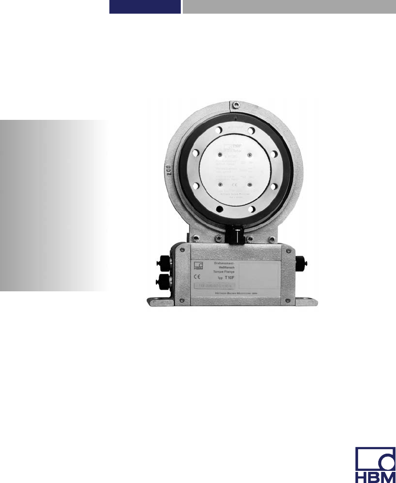
T10F
Hottinger Baldwin Messtechnik GmbH
Im Tiefen See 45
D-64239 Darmstadt
Tel. +49 6151 803-0
Fax +49 6151 803-9100
info@hbm.com
www.hbm.com
Mat.: 7-2001.1510
DVS: A0608-14.0 HBM: public
02.2015
E Hottinger Baldwin Messtechnik GmbH.
Subject to modifications.
All product descriptions are for general information only.
They are not to be understood as a guarantee of quality or
durability.

T10F A0608-14.0 HBM: public 3
English
1 Safety instructions 6........................................
2 Markings used 11............................................
2.1 The markings used in this document 11..........................
2.2 Symbols on the product 12.....................................
3 Torque flange versions 13....................................
4 Application 14...............................................
5 Structure and mode of operation 15...........................
6 Mechanical installation 17....................................
6.1 Conditions on site 19..........................................
6.2 Installation orientation 19......................................
6.3 Installation options 20.........................................
6.3.1 Installation without dismantling the antenna ring 21................
6.3.2 Installation with subsequent stator mounting 22...................
6.3.3 Installation example with couplings 23...........................
6.3.4 Installation example with joint shaft 23...........................
6.4 Mounting the rotor 24..........................................
6.5 Mounting the stator 28.........................................
6.6 Installing the clamp fixture 31...................................
6.7 Fitting the slotted disc (speed measuring system) 33..............
6.8 Aligning the stator (speed measuring system) 34..................
7 Electrical connection 37......................................
7.1 General information 37........................................
7.1.1 FCC and IC compliant installation for US and
Canada installation only 38.....................................
7.2 Shielding design 39...........................................
7.3 Option 2, code KF1 41........................................
7.3.1 Adaptation to the cable length 41...............................

4A0608-14.0 HBM: public T10F
7.4 Option 2, code SF1/SU2 43....................................
7.5 Supply voltage 46.............................................
8 Calibration 48...............................................
8.1 Calibration option 2, code KF1 49...............................
8.2 Calibration option 2, code SF1/SU2 49...........................
9 Settings 50..................................................
9.1 Torque output signal, code KF1 51..............................
9.2 Torque output signal, code SF1/SU2 51.........................
9.3 Setting up the zero point 51....................................
9.4 Functional testing 52..........................................
9.4.1 Power transmission 52........................................
9.4.2 Aligning the speed module 53..................................
9.5 Setting the pulse count 55.....................................
9.6 Vibration suppression (hysteresis) 56............................
9.7 Form of speed output signal 56.................................
9.8 Type of speed output signal 58.................................
10 Loading capacity 59.........................................
10.1 Measuring dynamic torque 59..................................
11 Maintenance 61..............................................
11.1 Speed module maintenance 61.................................
12 Dimensions 62..............................................
12.1 Rotor dimensions 62..........................................
12.2 Stator dimensions 64..........................................
12.3 Mounting dimensions 66.......................................

T10F A0608-14.0 HBM: public 5
13 Order numbers, accessories 68...............................
14 Specifications 70............................................
15 Supplementary technical information 78......................
15.1 Output signals 78.............................................
15.1.1 Output MD torque (connector 1) 78..............................
15.1.2 Output N: Speed (connector 2) 79...............................
15.1.3 Connector 2, double frequency, stat. direction of rotation signal 80..
15.2 Axial and radial run‐out tolerances 81............................
15.3 Additional mechanical data 82..................................

Safety instructions
6A0608-14.0 HBM: public T10F
1 Safety instructions
FCC Compliance & Advisory Statement
Important
Any changes or modification not expressly approved by
the party responsible for compliance could void the user's
authority to operate the device. Where specified addi
tional components or accessories elsewhere defined to
be used with the installation of the product, they must be
used in order to ensure compliance with FCC regulations.
This device complies with Part 15 of the FCC Rules.
Operation is subject to the following two conditions: (1)
this device may not cause harmful interference, and (2)
this device must accept any interference received, includ
ing interference that may cause undesired operation.
The FCC identifier or the unique identifier, as appropri
ate, must be displayed on the device.
Model Measuring range FCC ID IC
T10S2TO6
50 Nm, 100 Nm, 200 Nm
2ADAT-T10S2TOS6 12438A-T10S2TOS6
500 Nm, 1 kNm
2 kNm, 3 kNm
5 kNm
10 kNm
The FCC ID number in dependence of measuring range.
Safety instructions
T10F A0608-14.0 HBM: public 7
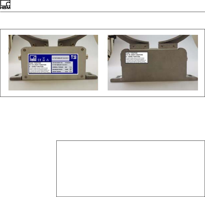
Fig. 1.1 Location of the label on the stator of the device
The preferred position of the FCC label is on the type
plate. If this is not possible for reasons of space, the
label can be found on the rear of the stator housing.
Model: 2ADAT-T10S2TOS6
FCC ID: 2ADAT-T10S2TOS6
IC: 12438AT10S2TOS6
This device complies with part 15 of the FCC Rules. Operation is
subject to the following two conditions: (1) This device may not
cause harmful interference, and (2) this device must accept any
interference received, including interference that may cause unde
sired operation.
Fig. 1.2 Label example with FCC ID and IC number
Industry Canada IC
This device complies with Industry Canada standard
RSS210.
This device complies with Industry Canada license-ex
empt RSS standard(s). Operation is subject to the follow
ing two conditions: (1) this device may not cause interfer
ence, and (2) this device must accept any interference,
including interference that may cause undesired opera
tion of the device.

Safety instructions
8A0608-14.0 HBM: public T10F
Cet appareil est conforme aux normes d'exemption de
licence RSS d'Industry Canada. Son fonctionnement est
soumis aux deux conditions suivantes : (1) cet appareil
ne doit pas causer d'interférence et (2) cet appareil doit
accepter toute interférence, notamment les interférences
qui peuvent affecter son fonctionnement.
Important
Usage/Installation in the USA and Canada requires an
EMI suppressor. Please refer to chapter 7.1.1, page 38.
Designated use
The T10F torque flange is used exclusively for torque
and rotation speed measurement tasks, and directly
associated control and regulatory tasks. Use for any
additional purpose shall be deemed to be not as
intended.
In the interests of safety, the transducer should only be
operated as described in the Operating Manual. It is also
essential to comply with the legal and safety
requirements for the application concerned during use.
The same applies to the use of accessories.
The transducer is not a safety element within the
meaning of its designated use. Proper and safe operation
of this transducer requires proper transportation, correct
storage, assembly and mounting, and careful operation.
General dangers of failing to follow the safety
instructions
The transducer corresponds to the state of the art and is
failsafe. The transducer can give rise to remaining
dangers if it is inappropriately installed and operated by
untrained personnel.

Safety instructions
T10F A0608-14.0 HBM: public 9
Everyone involved with mounting, starting up,
maintaining, or repairing the transducer must have read
and understood the Operating Manual and in particular
the technical safety instructions.
Residual dangers
The scope of supply and performance of the transducer
covers only a small area of torque measurement
technology. In addition, equipment planners, installers
and operators should plan, implement and respond to the
safety engineering considerations of torque
measurement technology in such a way as to minimize
remaining dangers. On‐site regulations must be complied
with at all times. Reference must be made to remaining
dangers connected with torque measurement
technology.
Conversions and modifications
The transducer must not be modified from the design or
safety engineering point of view except with our express
agreement. Any modification shall exclude all liability on
our part for any damage resulting therefrom.
Qualified personnel
The transducer must only be installed and used by
qualified personnel, strictly in accordance with the
specifications and with safety requirements and
regulations. It is also essential to comply with the legal
and safety requirements for the application concerned
during use. The same applies to the use of accessories.
Qualified personnel means persons entrusted with siting,
mounting, starting up and operating the product who
possess the appropriate qualifications for their function.

Safety instructions
10 A0608-14.0 HBM: public T10F
Accident prevention
According to the prevailing accident prevention
regulations, once the torque flange has been mounted, a
covering agent or cladding has to be fitted as follows:
SThe cover or cladding must not be free to rotate.
SThe cover or cladding should avoid squeezing or
shearing and provide protection against parts that
might come loose.
SCovers and cladding must be positioned at a suitable
distance or be arranged so that there is no access to
any moving parts within.
SCovers and cladding must also be attached if the
moving parts of the torque flange are installed outside
peoples' movement and operating range.
The only permitted exceptions to the above requirements
are if the various parts and assemblies of the machine
are already fully protected by the design of the machine
or by existing safety precautions.
Warranty
In the case of complaints, a warranty can only be given if
the torque flange is returned in the original packaging.
Markings used
T10F A0608-14.0 HBM: public 11
2 Markings used
2.1 The markings used in this document
Important instructions for your safety are specifically
identified. It is essential to follow these instructions in
order to prevent accidents and damage to property.
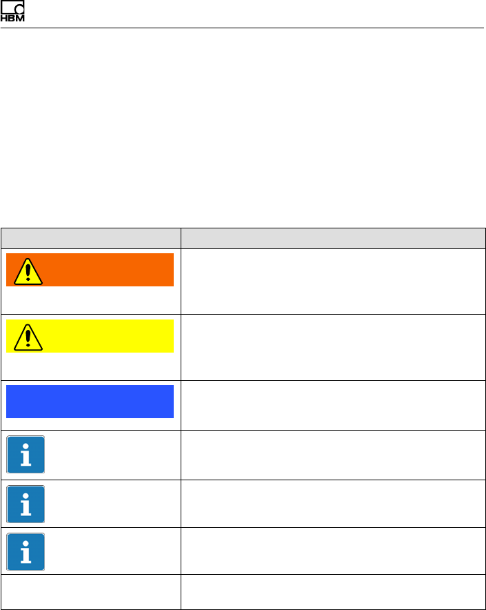
Symbol Significance
WARNING This marking warns of a potentially dangerous
situation in which failure to comply with safety
requirements can result in death or serious physical
injury.
CAUTION This marking warns of a potentially dangerous
situation in which failure to comply with safety
requirements can result in slight or moderate physical
injury.
Notice This marking draws your attention to a situation in
which failure to comply with safety requirements can
lead to damage to property.
Important
This marking draws your attention to important
information about the product or about handling the
product.
Tip
This marking indicates application tips or other
information that is useful to you.
Information
This marking draws your attention to information
about the product or about handling the product.
Emphasis
See….
Italics are used to emphasize and highlight text and
references to other chapters and external documents.
Markings used
12 A0608-14.0 HBM: public T10F
2.2 Symbols on the product
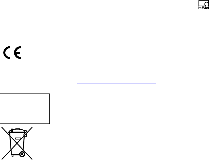
CE mark
The CE mark enables the manufacturer to guarantee that
the product complies with the requirements of the rele
vant EC directives (the declaration of conformity is avail
able at http://www.hbm.com/HBMdoc).
Label example
Label example with Model number, FCC ID and IC num
ber. Location on the stator of the device.
Statutory waste disposal mark
In accordance with national and local environmental
protection and material recovery and recycling
regulations, old devices that can no longer be used must
be disposed of separately and not with normal household
garbage.
If you need more information about waste disposal,
please contact your local authorities or the dealer from
whom you purchased the product.
Model: 2ADAT-T10S2TOS6
FCC ID: 2ADAT-T10S2TOS6
IC: 12438AT10S2TOS6
This device complies with part 15 of the
FCC Rules. Operation is subject to the
following two conditions: (1) This device
may not cause harmful interference, and
(2) this device must accept any interfer
ence received, including interference that
may cause undesired operation.
Torque flange versions
T10F A0608-14.0 HBM: public 13
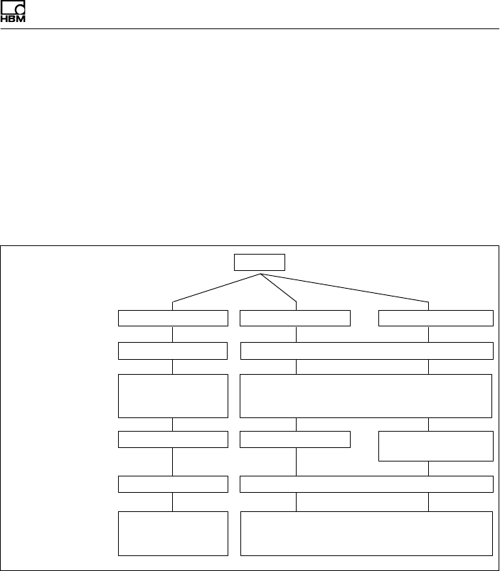
3 Torque flange versions
In the case of option 2 “Electrical configuration", the
T10F torque flange exists in versions KF1, SF1 and SU2.
The difference between these versions lies in the
electrical inputs and outputs on the stator, the rotors are
the same for all the versions of a measuring range.
Alternatively, versions SF1 and SU2 can be equipped
with a speed measuring system.
SF1
Measured
quantity
Type
Energy supply
Output signal
Can be connected
to HBM
measurement
electronics
Excitation voltage
54 VPP/14 kHz;
square‐wave
Torque
KF1
Connection
cable
FrequencyFrequency
V1 ... V4
Excitation voltage
generator in HBM
electronics
T10F
SU2
Supply voltage 18 V to 30 V DC
Separated extra‐low voltage (SELV circuit)
Excitation voltage generator in the torque flange
V5, V6, W1, W2
Frequency and
voltage
Torque and speed (option)
Fig. 3.1 T10F versions
You can find out which version you have from the stator
identification plate. The version is specified in the
“T10F-..." number there.
Example: T10F-001R-SU2-S-0-V1-Y (see also page 68).

Application
14 A0608-14.0 HBM: public T10F
4 Application
The T10F torque flanges record static and dynamic
torque on stationary or rotating shafts and determine the
speed, specifying the direction of rotation. Test beds can
be extremely compact because of their extremely short
construction. They therefore offer a very wide range of
applications.
In addition to conventional test‐bench engineering
(engine, roll and transmission test benches), new
solutions are possible for torque measurements partly
integrated in the machines. Here, you benefit in full from
the T10F torque flange special characteristics:
SExtremely compact construction with the
measurement flange body
SHigh permissible dynamic load
SHigh permissible lateral forces and bending moments
SVery high torsional stiffness
SNo bearings, no slip rings
Designed to work without bearings, and with contactless
excitation voltage and measured value transmission, the
measurement flanges are maintenance‐free. Thus there
are no friction or bearings heating effects.
The torque flanges are supplied for nominal (rated)
torques from 50 N⋅m to 10 kN⋅m. Depending on the
nominal (rated) torque, maximum speeds of up to 15 000
min-1 are permissible.
T10F torque flanges are reliably protected against
electromagnetic interference. They have been tested with
regard to EMC according to the relevant European
standards, and carry the CE mark.

Structure and mode of operation
T10F A0608-14.0 HBM: public 15
5 Structure and mode of operation
Torque flanges consist of two separate parts: the rotor
and the stator. The rotor comprises the measuring body
and the signal transmission elements.
Strain gauges (SGs) are mounted on the measuring
body. The rotor electronics for transmitting the bridge
excitation voltage and the measurement signal are
located centrally in the flange. The transmitter coils for
contactless transmission of excitation voltage and
measurement signal are located on the measuring body's
outer circumference. The signals are sent and received
by a separable antenna ring. The antenna ring is
mounted on a housing that includes the electronic
system for voltage adaptation and signal conditioning.
Connectors for the torque signal, the voltage supply and
the speed signal (option) are located on the stator. The
antenna ring should be mounted more or less
concentrically around the rotor (see chapter 6).
In the case of the speed measuring system option, the
speed sensor is mounted on the stator, the customer
attaches the associated slotted disc on the rotor. The
speed measurement works optically with the infrared
transmitted light barrier principle.
Structure and mode of operation
16 A0608-14.0 HBM: public T10F
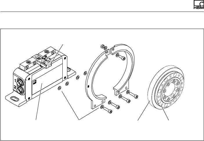
Stator
Antenna segments
Rotor
Fan‐type lock
washers
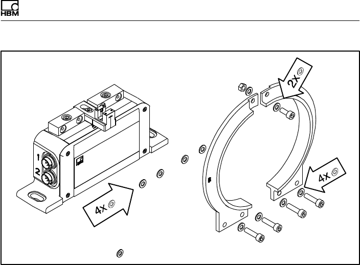
Speed sensor (option)
Measuring
body
Adapter flange
(without slotted disc)
Housing
Fig. 5.1 Mechanical structure, exploded view

Mechanical installation
T10F A0608-14.0 HBM: public 17
6 Mechanical installation
WARNING
Handle the torque flange carefully! The transducer could
suffer permanent damage from mechanical shock
(dropping), chemical effects (e.g. acids, solvents) or
thermal effects (hot air, steam).
With alternating loads, you should cement the rotor
connection screws into the mating thread with a screw
locking device (medium strength) to exclude prestressing
loss due to screw slackening.
An appropriate shaft flange enables the T10F torque
flanges to be mounted directly. It is also possible to
mount a joint shaft or relevant compensating element
directly on the rotor (using an intermediate flange when
required). Under no circumstances must the permissible
limits specified for bending moments, lateral and
longitudinal forces be exceeded. Due to the T10F torque
flanges' high torsional stiffness, dynamic changes on the
shaft train are minimized.
Important
The effect on critical bending speeds and natural
torsional vibrations must be checked to avoid overloading
the measurement flanges due to the resonance stepup.

Mechanical installation
18 A0608-14.0 HBM: public T10F
Important
Even if the unit is installed correctly, the zero point
adjustment made at the factory can shift by
approx. ±150 Hz. If this value is exceeded, we advise
you to check the mounting conditions.
Important
For correct operation, comply with the mounting
dimensions (see page 66).

Mechanical installation
T10F A0608-14.0 HBM: public 19
6.1 Conditions on site
T10F torque flanges are protected to IP54 according to
EN 60529. The measuring hubs must be protected
against coarse dirt particles, dust, oil, solvents and
humidity. During operation, the prevailing safety
regulations for the security of personnel must be
observed (see chapter 1 „Safety instructions“, page 6).
There is wide ranging compensation for the effects of
temperature on the output and zero signals of the T10F
torque flange (see chapter 14 “Specifications”, page 70).
This compensation is carried out at static temperatures in
extensive furnace processes. This guarantees that the
circumstances can be reproduced and the properties of
the transducer can be reconstructed at any time.
If there are no static temperature ratios, for example,
because of the temperature differences between the
measuring body and the flange, the values given in the
specifications can be exceeded. So, for accurate
measurements, static temperature conditions must then
be obtained by cooling or heating depending on the
application. As an alternative, check thermal decoupling
by means of heat radiating elements such as multi‐disc
couplings.
6.2 Installation orientation
The measurement flange can be mounted in any
position. With clockwise torque, the output frequency is
10 kHz to 15 kHz. With HBM amplifiers or with the
“voltage output" option, a positive output signal (0 V ...
+10 V) is present.
In the case of the speed measuring system, an arrow is
attached to the head of the sensor to clearly define the

Mechanical installation
20 A0608-14.0 HBM: public T10F
direction of rotation. If the measurement flange moves in
the direction of the arrow, connected HBM measuring
amplifiers deliver a positive output signal (0 V ... +10 V).
6.3 Installation options
In principle, there are two possibilities for torque flange
mounting: with the antenna ring complete or dismantled.
We recommend mounting as described in chapter 6.3.1.
“Installation without dismantling the antenna ring” If
installation in accordance with chapter 6.3.1 is not
possible, (e.g. in the case of subsequent stator
replacement or mounting with a speed measuring
system), you will have to dismantle the antenna ring. It is
essential in this case to comply with the notes on
assembling the antenna segments (see chapter 6.5
“Mounting the stator” on page 28 and chapter 6.7
“Fitting the slotted disc (speed measuring system)” on
page 33).
Mechanical installation
T10F A0608-14.0 HBM: public 21
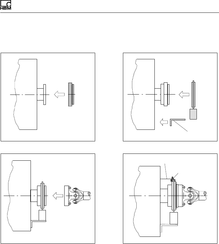
6.3.1 Installation without dismantling the antenna
ring
1. Install rotor 2. Install stator
3. Finish installation of shaft train
Customer mounting
Support supplied by customer
Clamp fixture
4. Mount the clamp fixture where required
Mechanical installation
22 A0608-14.0 HBM: public T10F
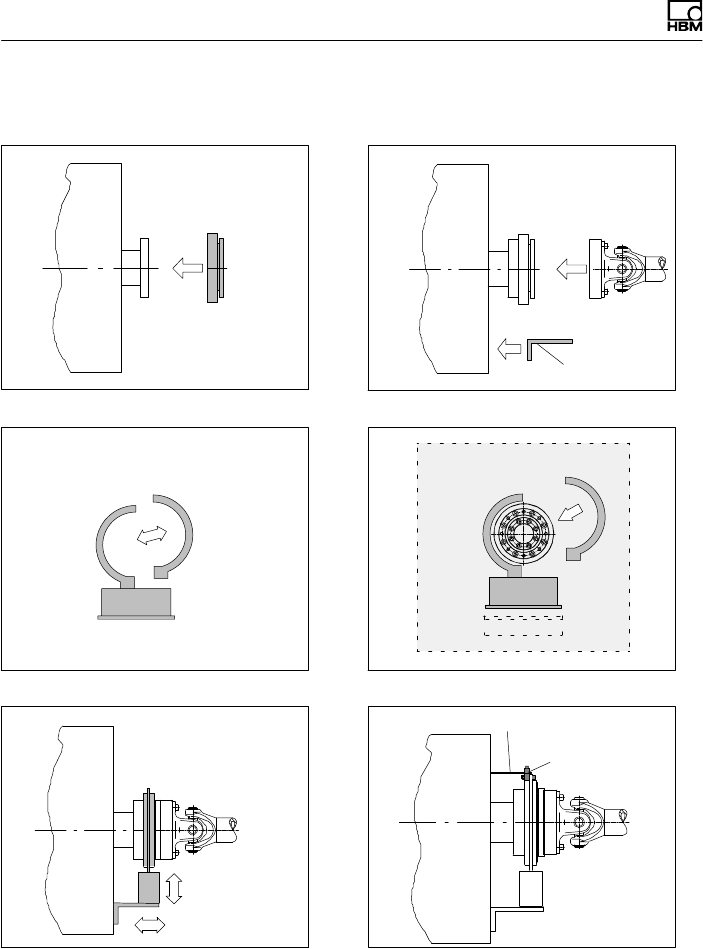
6.3.2 Installation with subsequent stator mounting
2. Install shaft train
3. Remove one antenna segment
5. Align stator and finish installation
4. Install antenna segment around shaft train
Support supplied by customer
Clamp fixture
6. Mount the clamp fixture where required
Customer mounting
.
.
Mechanical installation
T10F A0608-14.0 HBM: public 23
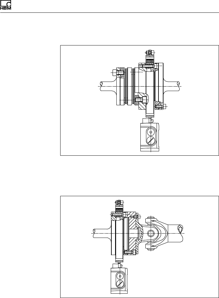
6.3.3 Installation example with couplings
Fig. 6.1 Installation example with coupling
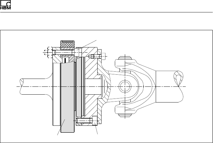
6.3.4 Installation example with joint shaft
Fig. 6.2 Installation example with joint shaft

Mechanical installation
24 A0608-14.0 HBM: public T10F
6.4 Mounting the rotor
Important
For correct operation, comply with the mounting
dimensions (particularly the area free of metal, see
page 66).
Additional installation notes for the speed measuring
system can be found in chapter 6.7, page 33.
Important
Usually the rotor identification plate is no longer visible
after installation. This is why we include with the rotor
additional stickers with the important ratings, which you
can attach to the stator or any other relevant test‐bench
components. You can then refer to them whenever there
is anything you wish to know, such as the calibration
signal.
1. Prior to installation, clean the plane surfaces of the
measurement flanges and counter flanges. For safe
torque transfer, the surfaces must be clean and free
from grease. Use a piece of cloth or paper soaked in
solvent. When cleaning, make sure that you do not
damage the transmitter coils.
Mechanical installation
T10F A0608-14.0 HBM: public 25
6x or 8x (Z) DIN EN ISO 4762
hexagonsocket screws (10.9/12.9)
8x fastening screws (10.9/12.9); note
maximum screw‐in depth Y!
Measuring body
Fig. 6.3 Screwed rotor joint
2. For the bolted rotor connection, use eight DIN EN
ISO 4762 property class 10.9 hexagon socket screws
(measuring range 10 kNVm: 12.9) of a suitable length
(dependent on the connection geometry, see
Fig. 6.4).
We recommend, particularly for 50 N⋅, 100 N⋅m and
200 N⋅m, fillisterhead screws DIN EN ISO 4762...,
blackened, smoothheaded, oiled, mtot 0.125 permitted
size and shape variance in accordance with
DIN ISO 4759, Part 1, product class A.
Mechanical installation
26 A0608-14.0 HBM: public T10F
WARNING
The screw heads (Z), see Fig. 6.4, must not touch the
adapter flange.
With alternating load: Use a screw locking device
(e.g. LOCTITE no. 242) to glue the screws into the
counter thread to exclude prestressing loss due to screw
slackening.
3. Before the final tightening of the screws, rotate the
torque flange on the centering device until all screw
heads are positioned approximately centrally in the
through‐holes of the connection element. The screw
heads must not touch the walls of the through‐holes in
the adapter flange!
4. Fasten all screws with the specified tightening torque
(see Fig. 6.4).
5. For further mounting of the shaft train, there are eight
tapped holes on the adapter flange. Also use screws
of property class 10.9 (or 12.9) and fasten with the
torque specified in Fig. 6.4.
Important
With alternating loads, use a screw locking device to
cement the connecting screws into place! Guard against
contamination from varnish fragments.
The maximum screw‐in depth as per Fig. 6.4 must be
complied with! Otherwise, significant measurement errors
may result from torque shunts or the transducer may be
damaged.

Mechanical installation
T10F A0608-14.0 HBM: public 27
Nominal
(rated)
torque
(NVm)
Fastening
screws
(Z)1)
Fastening
screws
Property class
Max. screw‐in depth
(Y) of screws in the
adapter flange
(mm)
Prescribed
tightening
torque
(NVm)
50 M6 10.9 7.52) 14
100
200 M8 11 34
500 M12 18 115
1 k M12 18 115
2 k M14 18 185
3 k M14 26 185
5 k M18 33.5 400
10 k M18 12.93) 33.5 470
1) DIN EN ISO 4762; black/oiled/mtot = 0.125
2) 14 mm for speed module option; use 6 mm longer screws because of the intermediate flange.
3) If property class 12.9 screws are not available, class 10.9 screws can also be used (tightening
torque 400 N⋅m). The permissible limit torque then reduces to 120% related to Mnom.
Fig. 6.4 Fastening screws

Mechanical installation
28 A0608-14.0 HBM: public T10F
6.5 Mounting the stator
On delivery, the stator has already been installed and is
ready for operation. The antenna segments can be
separated from the stator, for example, for maintenance
or to facilitate stator mounting. To stop you modifying the
center alignment of the segment rings opposite the base
of the stator, we recommend that you separate only one
antenna segment from the stator.
If your application does not require the stator to be
dismantled, proceed as described in points 2., 6., 7.
and 8.
Version with speed measuring system
As the speed sensor includes the slotted disc, it is not
possible to move the stator axially over the
pre‐assembled rotor (exception: Measuring ranges
50 N⋅m, 100 N⋅m and 200 N⋅m).
In this case, you should also comply with chapter 6.7
“Fitting the slotted disc (speed measuring system)”,
page 33.
Important
Check the screw connections of the antenna segments
(see Fig. 6.5) both after initial installation and then at
regular intervals for correct fit and tighten them if
necessary.
Mechanical installation
T10F A0608-14.0 HBM: public 29
Fan‐type lock washer
Fig. 6.5 Screw fittings of the antenna segments
1. Loosen and remove the screw fittings (M5) on one
antenna segment. Make sure that the fan‐type lock
washers are not lost!
2. Use an appropriate base plate to install the stator
housing in the shaft train so that there is sufficient
possibility for horizontal and vertical adjustments. Do
not fully tighten the screws yet.
3. Now reinstall the antenna segment removed under
point 1. on the stator with two hexagon‐socket screws
and the fan‐type lock washers. Make sure that none
of the fan‐type lock washers necessary for a defined
contact resistance are missing (see Fig. 6.5)! Do not
yet tighten the screws.
Mechanical installation
30 A0608-14.0 HBM: public T10F
4. Install the two antenna segments' upper connecting
screw so that the antenna ring is closed. Also pay
attention to the fantype lock washers.
5. Now fasten all the bolted antenna‐segment
connections with a tightening torque of 5 N⋅m.
6. Align the antenna and rotor so that the antenna
encloses the rotor coaxially. Please comply with the
permissible alignment tolerances stated in the
specifications.
7. Now fully tighten the bolted stator housing connection.
8. Make sure that the gap in the lower antenna segment
area is free of electrically conductive foreign bodies.
Gap
Important
To guarantee that they function perfectly, the fan‐type
lock washers (A5, 3-FST DIN 6798 ZN/galvanized) must
be replaced after the bolted antenna connection has
been loosened three times.
Mechanical installation
T10F A0608-14.0 HBM: public 31
6.6 Installing the clamp fixture
Depending on the operating conditions, oscillations may
be induced in the antenna ring. This effect is dependent
on:
Sthe speed
Sthe antenna diameter (depends in turn on the
measuring range)
Sthe design of the machine base
To avoid vibrations, a clamp fixture is enclosed with the
torque flange enabling the antenna ring to be supported.
Support supplied by customer
Clamp fixture
Antenna ring
Fig. 6.6 Supporting the antenna ring
Mounting sequence
1. Loosen and remove the upper antenna segment
screw fitting.
2. Fasten the clamp fixture with the enclosed screw
fitting as shown in Fig. 6.7. It is essential to use the
new fan‐type locking washers!
Mechanical installation
32 A0608-14.0 HBM: public T10F
3. Clamp a suitable support element (we recommend a
threaded rod ∅ 3…6mm) between the upper and
lower parts of the clamp fixture and tighten the
clamping screws.
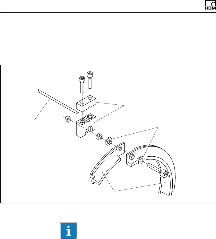
Support
supplied by the
customer, e.g.
threaded rod
Clamp fixture
Fan‐type lock
washers
Antenna segments
Fig. 6.7 Installing the clamp fixture
Important
Use, e.g. plastic as the material. Do not use metallic
material as this can affect the function of the antenna
(signal transmission).
Mechanical installation
T10F A0608-14.0 HBM: public 33
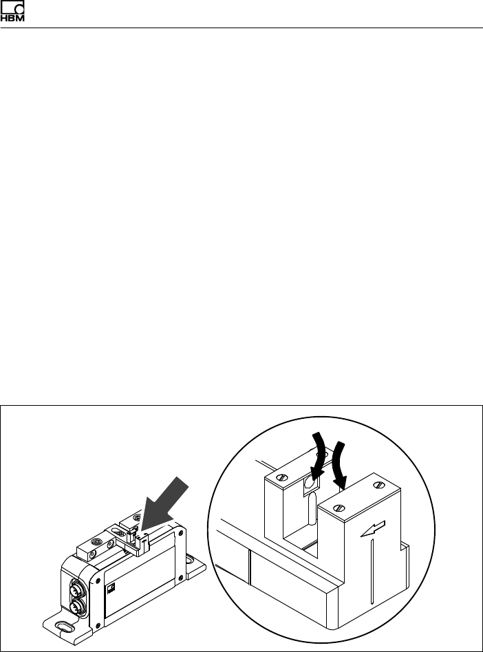
6.7 Fitting the slotted disc
(speed measuring system)
To prevent damage to the optical speed measuring
systems' slotted disc during transportation, it is not
mounted on the rotor. Before installing the rotor in the
shaft train, you must attach it to the adapter flange (or
intermediate flange). The associated speed sensor is
already mounted on the stator.
The requisite screws, a suitable screwdriver and the
screw locking device are included in the list of
components supplied.
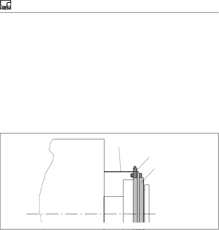
Screw for fastening the
slotted disc with slotted disc
turned in the cutting plane
Slotted disc
Intermediate flange
(50 N⋅m and 100 N⋅m only)
Fig. 6.8 Installing the slotted disc
Important
At all stages of the mounting operation, be careful not to
damage the slotted disc!

Mechanical installation
34 A0608-14.0 HBM: public T10F
Mounting sequence
1. Push the slotted disc onto the adapter flange (or
additional flange) and align the screw holes.
2. Apply some screw locking device to the screw thread
and tighten the screws (tightening torque < 15 N⋅cm).
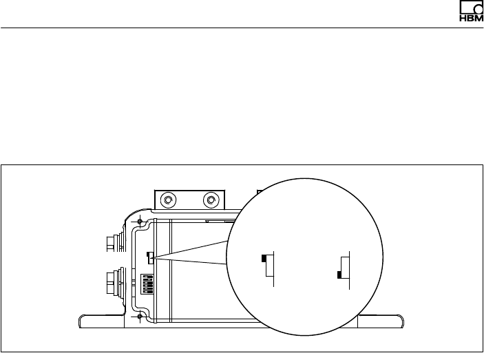
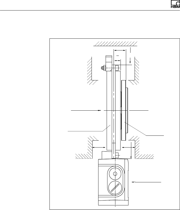
6.8 Aligning the stator
(speed measuring system)
The stator can be mounted in any position (for example,
“upside down" installation is possible). For perfect
measuring mode, the slotted disc of the speed measuring
system must rotate at a defined position in the sensor
pickup.
Axial alignment
There is a mark (orientation line) in the sensor pickup for
axial alignment (orientation line). When installed, the
slotted disc should be exactly above this orientation line.
Divergence of up to "2 mm is permissible in measuring
mode (total of static and dynamic shift).
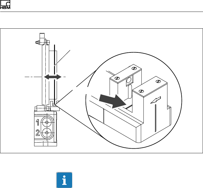
Mechanical installation
T10F A0608-14.0 HBM: public 35
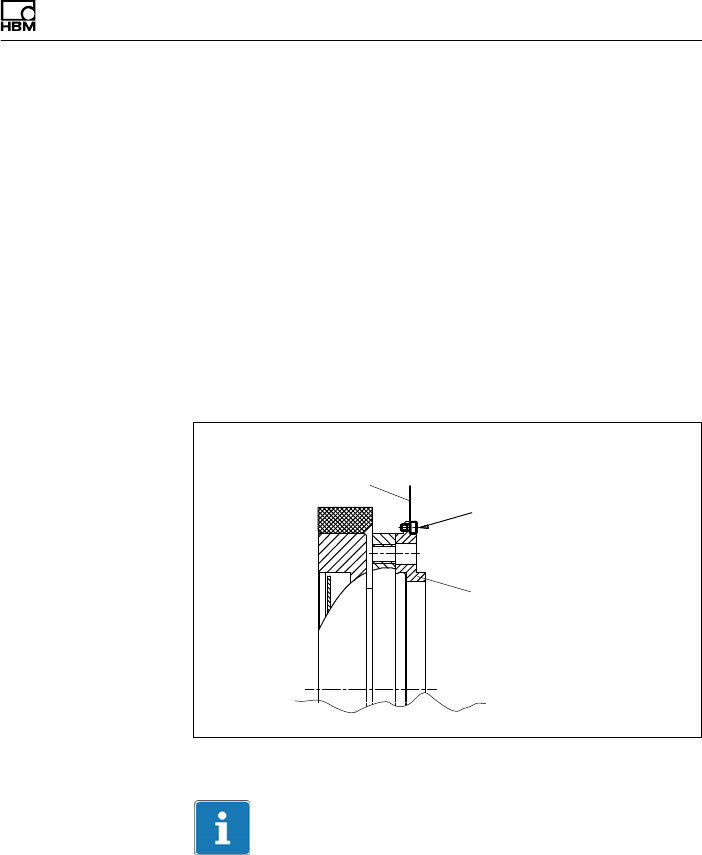
Alignment line
Slotted disc
Fig. 6.9 Position of the slotted disc in the speed sensor
Important
To attach the stator, we recommend the use of M6
screws with plain washers (width of oblong hole, 9 mm).
This size of screw guarantees the necessary travel for
alignment.
Radial alignment
The rotor axis and the optical axis of the speed sensor
must be along a line at right angles to the stator platform.
A conical machined angle (or a colored mark) in the
center of the adapter flange and a vertical marker line on
the sensor head serve as aids to orientation.
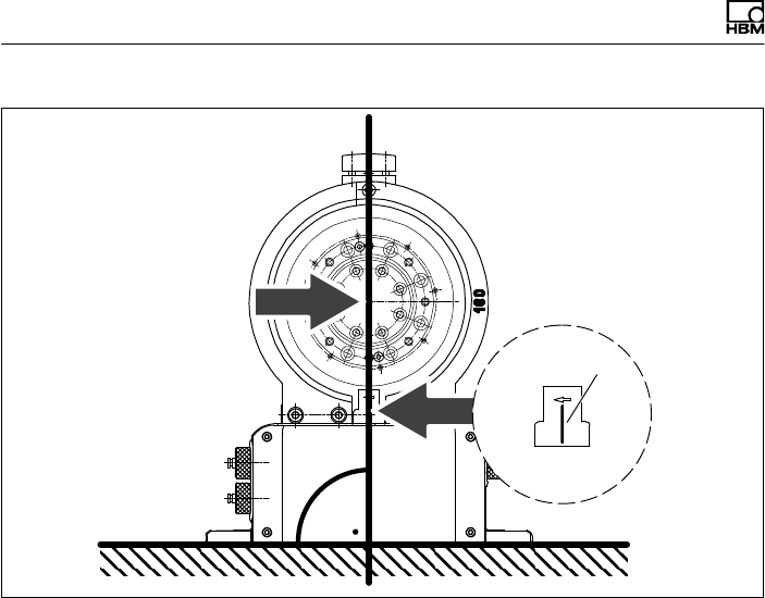
Mechanical installation
36 A0608-14.0 HBM: public T10F
Centering point for
aligning the rotor
Marking
Sensor head
Fig. 6.10 Alignment marks on rotor and stator

Electrical connection
T10F A0608-14.0 HBM: public 37
7 Electrical connection
7.1 General information
To make the electrical connection between the torque
transducer and the amplifier, we recommend using
shielded, low‐capacitance measurement cables from
HBM.
With cable extensions, make sure that there is a proper
connection with minimum contact resistance and good
insulation. All plug connections or swivel nuts nuts must
be fully tightened.
Do not route the measurement cables parallel to power
lines and control circuits. If this cannot be avoided (in
cable pits, for example), maintain a minimum distance of
50 cm and also draw the measurement cable into a steel
tube.
Avoid transformers, motors, contactors, thyristor controls
and similar stray‐field sources.
Important
Transducer connection cables from HBM with attached
connectors are identified in accordance with their
intended purpose (Md or n). When cables are shortened,
inserted into cable ducts or installed in control cabinets,
this identification can get lost or become concealed. If
this is the case, it is essential for the cables to be
re‐labeled!
Electrical connection
38 A0608-14.0 HBM: public T10F
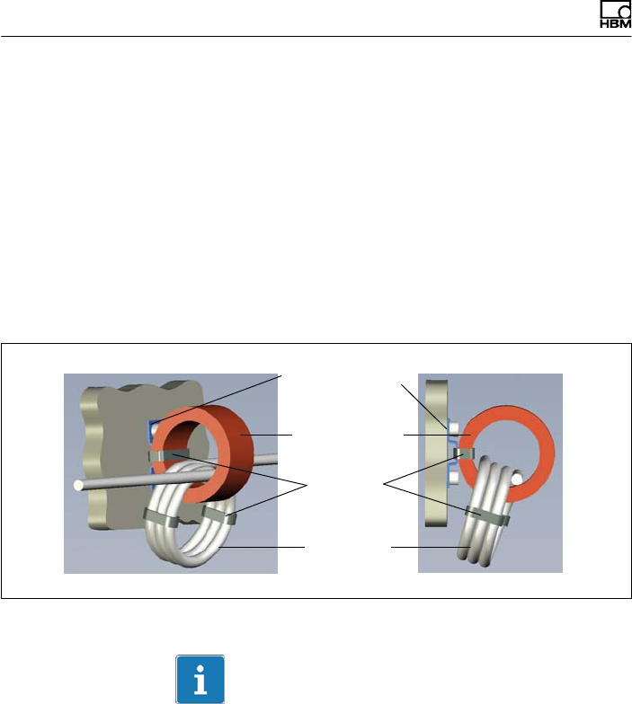
7.1.1 FCC and IC compliant installation for US and
Canada installation only
Use of EMI suppressor
To suppress high frequencies a EMI suppressor on the
power cable has to be used. Use at least 3 loops of the
cable.
Fastening must be done in an area not subject to
mechanical loads (i.e. no unwanted vibrations, etc.) using
cable ties fit for the specific application.
EMI suppressor
Cable ties
Mounting fixture
3 Loops
Fig. 7.1 Installation example EMI suppressor
Information
Consider longer cable of approximately 40 cm due to the
installation of the EMI suppressor.
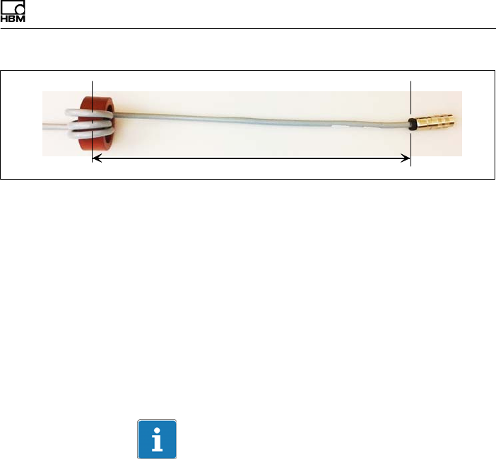
Electrical connection
T10F A0608-14.0 HBM: public 39
500 mm
Fig. 7.2 Max. distance of EMI suppressor to connector
If the EMI suppressor has to be removed for any purpose
(e.g. for maintenance), it must be replaced on the cable.
Use only EMI suppressor of the correct type.
Type: Vitroperm R
Model No.: T60006-22063W517
Size: external diameter x internal diameter x height =
63 x 50 x 25
The installation requires a EMI suppressor to be added to
the cable. Additional fixture should be used to prevent
stress on the connector due to extra weight of the cable.
Important
The use of the EMI suppressor on the power cable
(plug 1 or plug 3) is mandatory to ensure compliance
with FCC regulations.
7.2 Shielding design
The cable shield is connected in accordance with the
Greenline concept. This encloses the measurement
system (without the rotor) in a Faraday cage. It is
important that the shield is laid flat on the housing ground
at both ends of the cable. Any electromagnetic
interference active here does not affect the measurement

Electrical connection
40 A0608-14.0 HBM: public T10F
signal. Special electronic coding methods are used to
protect the transmission path and the rotor from
electromagnetic interference.
In the case of interference due to potential differences
(compensating currents), operating voltage zero and
housing ground must be disconnected on the amplifier
and a potential equalization line established between the
stator housing and the amplifier housing (copper
conductor, 10 mm2 wire cross-section).
If potential differences arise between the rotor and the
stator on the machine, perhaps due to unchecked
leakage, and this causes interference, it can usually be
overcome by connecting the rotor directly to ground, for
instance by a wire loop. The stator should be fully
grounded in the same way.
Electrical connection
T10F A0608-14.0 HBM: public 41
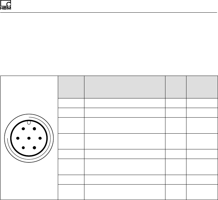
7.3 Option 2, code KF1
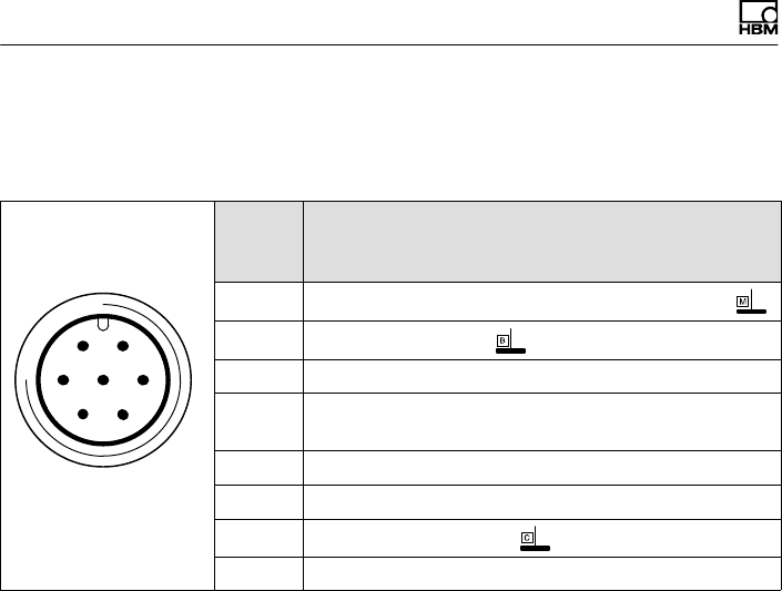
The stator housing has a 7‐pin (Binder 723) device
connector, to which you link the connection cable for
voltage supply and torque signal.
61
572
43
Binder 723
Top view
Conn.
Binder
Pin
Assignment Wire
color
MS3106
conn.
Pin
1Supply voltage zero wh A
2No function bk B
3Pre‐amplifier supply voltage
(+15 V)
bu C
4Torque measurement signal
(12 VPP; 5...15 kHz)
rd D
5No function
6Rotor excitation voltage
(54 V/80 VPP; approx.15 kHz)
gn F
7Rotor excitation voltage (0 V) gy G
Shielding connected to
housing ground
7.3.1 Adaptation to the cable length
The transmission method between the rotor and the
stator determines the function of the torque flange, which
is dependent on:
Sthe installation situation (for example, covering, area
free of metal parts)
Sthe length of the cable
Sthe tolerances of the excitation voltage supply
Electrical connection
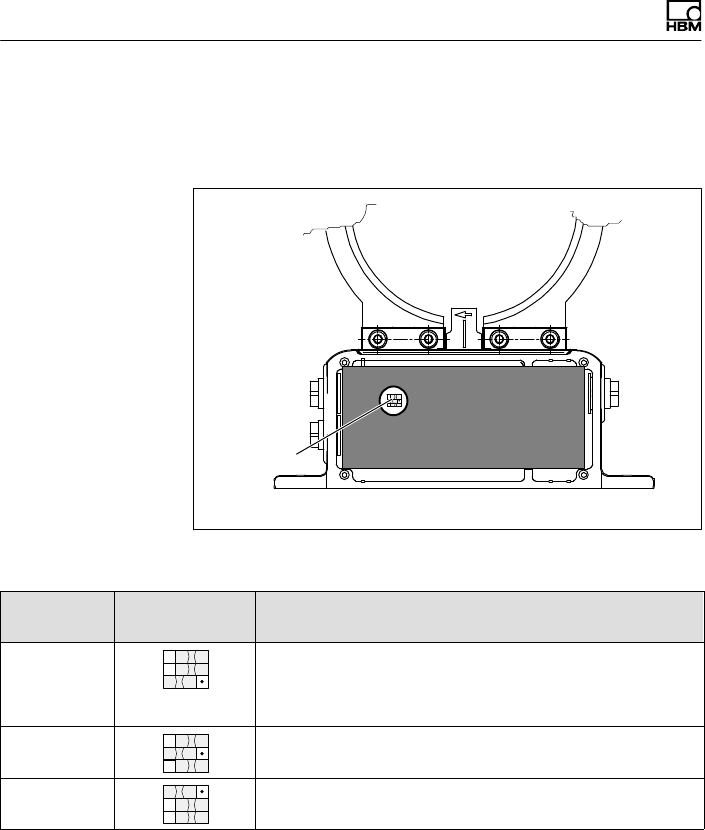
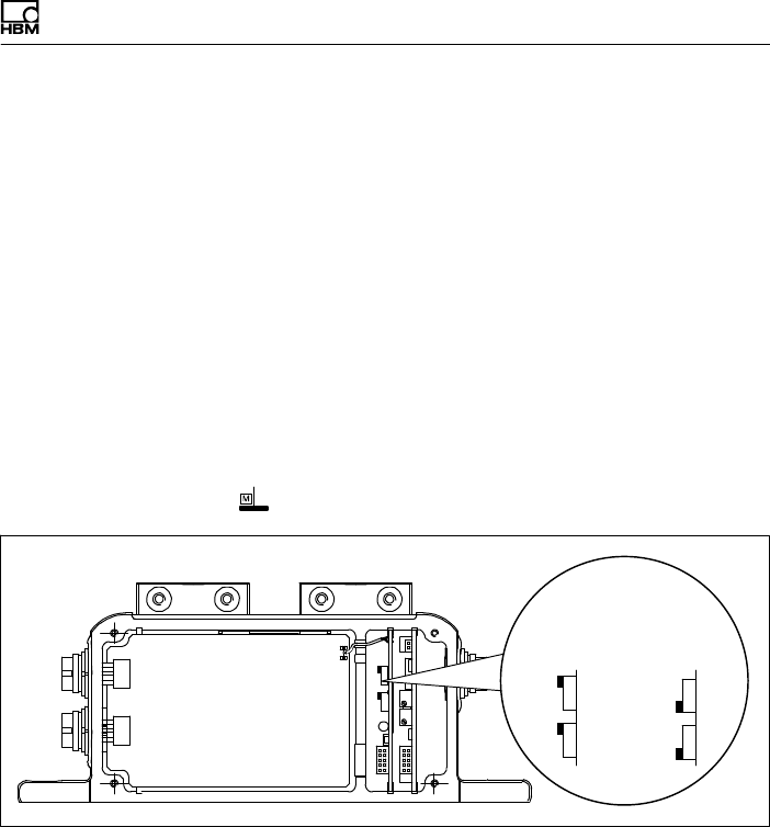
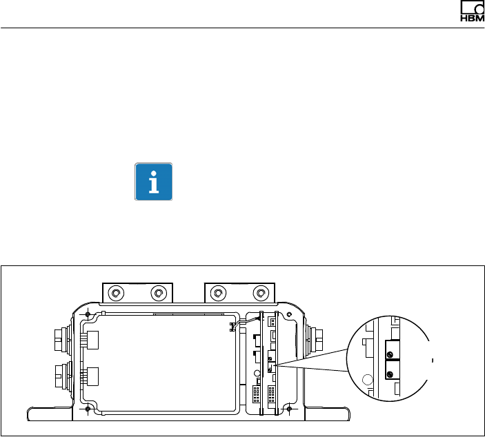
42 A0608-14.0 HBM: public T10F
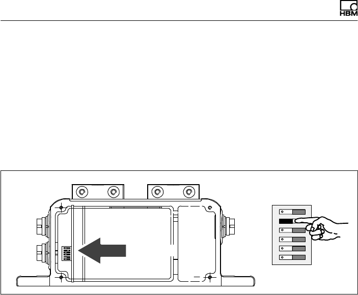
To allow for adaptation to various conditions, there are
three switches in the stator housing, which can be
accessed by removing the stator cover.
Switches
Fig. 7.3 Switches in the stator housing
Switch
position
Example applications
1a) Older amplifiers
b) For when the calibration signal is unintentionally
initiated with very short cables
2Normal position (factory setting)
3For cable lengths in excess of approx. 20 m
Please ensure that after changing to switch position 3,
the calibration signal is not initiated.

Electrical connection
T10F A0608-14.0 HBM: public 43
Possible faults and their elimination:
Fault: No signal at the output, amplifier indicates overflow.
Cause: Too little power, T10F disconnects.
Remedy: Switch position 3.
Fault: The calibration signal has been triggered by mistake.
Remedy: Switch position 1.
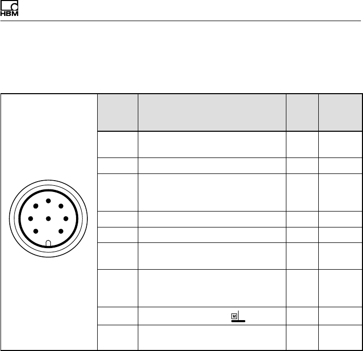
7.4 Option 2, code SF1/SU2
On the stator housing, there are two 7‐pin device
connectors (Binder 723) and in the case of the speed
module option, there is also an 8‐pin device connector,
assigned in accordance with the selected option.
The supply voltage and the calibration signal of
connectors 1 and 3 are direct‐coupled via multifuses
(automatically resetting fuses).
Assignment for connector 1
Voltage supply and frequency output signal.
Electrical connection
44 A0608-14.0 HBM: public T10F
61
572
43
Binder 723
Top view
Binder
conn.
Pin
Assignment Wire
color
Sub‐D
conn.
Pin
1Torque measurement signal
(frequency output; 5 V1; 0 V)
wh 13
2Supply voltage 0 V; bk 5
3Supply voltage 18 V ... 30 V bu 6
4Torque measurement signal
(frequency output; 5 V1/12) V)
rd 12
5Measurement signal 0 V;
symmetrical
gy 8
6Calibration signal trigger 5 V -
30 V
gn 14
7Calibration signal 0 V; gy 8
Shielding connected to housing
ground
1) Factory setting; complementary signals RS-422
Important
The torque flanges of option 3, code SF1/SU2 are only
intended for operation with a DC supply voltage. They
must not be connected to older HBM amplifiers with
square‐wave excitation. This could lead to the
destruction of the connection board resistances or other
errors in the measuring amplifiers (the torque flange, on
the other hand, is protected and once the proper
connections have been re‐established, is ready for
operation again).
Electrical connection
T10F A0608-14.0 HBM: public 45
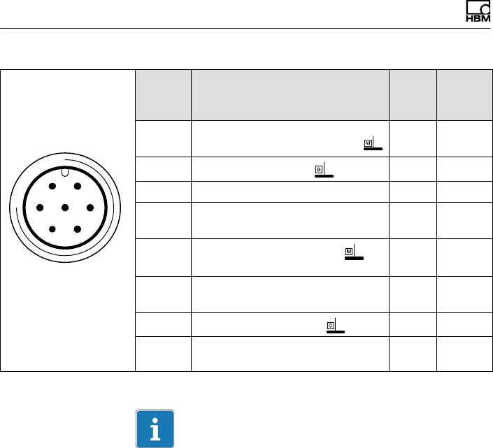
Assignment connector 2
Speed measuring system
6
1
5
7
2
4
38
Binder 723
Top view
Conn.
Binder
Pin
Assignment Wire
color
Sub‐D
conn.
Pin
1Speed measurement signal (pulse
string, 5 V1; 0°)
rd 12
2No function - -
3Speed measurement signal
(pulse string, 5 V1; phase‐shifted
by 90°)2
gy 15
4No function - -
5No function - -
6Speed measurement signal (pulse
string, 5 V1; 0°)
wh 13
7Speed measurement signal
(pulse string, 5 V1; phase‐shifted
by 90°)2
gn 14
8Supply voltage zero bk 8
Shielding connected to housing
ground
1) RS-422 complementary signals
2) When switching to double frequency, static direction of rotation signal.
Electrical connection
46 A0608-14.0 HBM: public T10F
Assignment connector 3
Voltage supply and voltage output signal.
61
572
43
Binder 723
Top view
Conn.
Binder
Pin
Assignment
1Torque measurement signal (voltage output; 0 V )
2Supply voltage 0 V;
3Supply voltage 18 V ... 30 V DC
4Torque measurement signal (voltage output;
"10 V)
5No function
6Calibration signal trigger 5 V - 30 V
7Calibration signal 0 V;
Shielding connected to housing ground
7.5 Supply voltage
The transducer must be operated with a separated
extra‐low voltage (18...30 V DC supply voltage), which
usually supplies one or more consumers within a test
bench.
Should the equipment be operated on a DC voltage
network1), additional precautions must be taken to
discharge excess voltages.
The notes in this chapter relate to the standalone
operation of the T10F without HBM system solutions.
1) Distribution system for electrical energy with greater physical expansion (over several test
benches, for example) that may possibly also supply consumers with high nominal (rated)
currents.
Electrical connection
T10F A0608-14.0 HBM: public 47
The supply voltage is electrically isolated from signal
outputs and calibration signal‐inputs. Connect a
separated extra‐low voltage of 18 V ... 30 V to pin 3 (+)
and pin 2 ( ) of connector 1 or 3. We recommend that
you use HBM cable KAB 8/00-2/2/2 and relevant Binder
sockets, that at nominal (rated) voltage (24 V) can be up
to 50 m long and in the nominal (rated) voltage range,
20m long (see chapter 13 “Order numbers, accessories”,
page 68).
If the permissible cable length is exceeded, you can feed
the supply voltage in parallel over two connection cables
(connectors 1 and 3). This enables you to double the
permissible length. Alternatively an on‐site power pack
should be installed.
If you feed the supply voltage through an unshielded
cable, the cable must be twisted (interference
suppression). We also recommend that a ferrite element
should be located close to the connector plug on the
cable, and that the stator should be grounded.
Important
At the instant of power‐up, a current of up to 2 A may
flow, which could switch off power packs with electronic
current limiters.

Calibration
48 A0608-14.0 HBM: public T10F
8 Calibration
The T10F torque flange delivers an electrical calibration
signal that can be switched at the amplifier end for
measurement chains with HBM components. The
measurement flange generates a calibration signal of
about 50 % of the nominal (rated) torque. The precise
value is specified on the type plate. Adjust the amplifier
output signal to the calibration signal supplied by the
connected torque flange to adapt the amplifier to the
measurement flange.
To obtain stable conditions, the calibration signal should
only be activated once the transducer has been warming
up for 15 minutes.
The framework conditions for comparability (e.g.
installation situation) must be implemented in order to
reproduce the measured values in the test certificate.
Important
The measurement flange should not be under load when
the calibration signal is being measured, since the
calibration signal is mixed additively.
Important
To maintain measurement accuracy, the calibration sig
nal should be connected for no more than 5 minutes. A
similar period is then needed as a cooling phase before
triggering the calibration signal again.

Calibration
T10F A0608-14.0 HBM: public 49
8.1 Calibration option 2, code KF1
Increasing the excitation voltage from 54VPP to 80VPP
(pins 6 and 7, connector 1), triggers the calibration
signal.
8.2 Calibration option 2, code SF1/SU2
Applying a separated extra‐low voltage of 5 V to pin 6 (+)
and 7 ( ) on connector 1 or 3 triggers the calibration
signal.
The nominal (rated) voltage for triggering the calibration
signal is 5 V (triggered when U>2.7 V). The trigger
voltage is electrically isolated from the supply voltage and
the measurement voltage. The maximum permissible
voltage is 30 V. When voltages are less than 0.7 V, the
measurement flange is in measuring mode. Current
consumption at nominal (rated) voltage is approx. 2mA
and at maximum voltage is approx. 22mA.
Important
In the case of HBM system solutions, the measuring
amplifier triggers the calibration signal.
Settings
50 A0608-14.0 HBM: public T10F
9 Settings
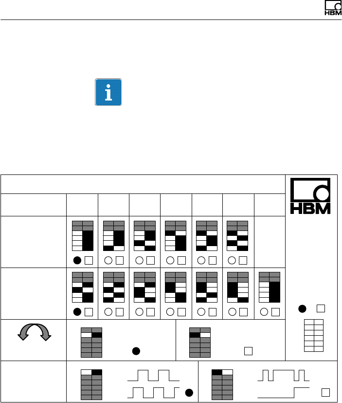
Important
You will find a table containing all the relevant switch
positions on the back of the stator cover. Changes to the
factory settings should be noted or entered here using a
waterproof felt‐tip pen.
Impulse/Umdrehung
Pulses/revolution 720
360 180 90 60 30 15
Einstellungen / Settings OPTION 5
Mnom
100 N⋅m
to 3 kN⋅m
Mnom
5 kN⋅m
to 10 kN⋅m
Hysterese
Hysteresis
ein/on aus/off
CH1
CH2
Frequenz
Ausgangsspannung
Frequency output
voltage
ON DIP
1 2 3 4 5 6
WERKSEINSTELLUNG
Factory settings
Eigene Einstellungen
Customized settings
CH1
CH2
2xf
0
+-
Fig. 9.1 Sticker with switch positions; optical speed
measuring system
Settings
T10F A0608-14.0 HBM: public 51
9.1 Torque output signal, code KF1
The factory setting for the frequency output voltage is 12
V (asymmetrical). The frequency signal is on pin 4
opposite pin 1. It is not possible to change over.
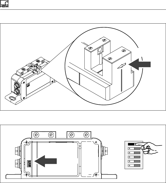
9.2 Torque output signal, code SF1/SU2
The factory setting for the frequency output voltage is 5 V
(symmetrical, complementary RS-422 signals). The
frequency signal is on pin 4 opposite pin 1. You can
change the output voltage to 12 V (asymmetrical). To do
this, change switches S1 and S2 to position 1 (and pin 1
→ ).
12 V
asymmetrical
5 V
symmetrical
Pos.1
Pos.2 S1
S2
Fig. 9.2 Switch for changing the frequency output voltage
9.3 Setting up the zero point
In the case of the torque flange with the voltage output
option (SU2), you can access two potentiometers by
removing the stator cover. You can use the zero point
potentiometer to correct zero point deviations caused by
Settings
52 A0608-14.0 HBM: public T10F
the installation. The balancing range is a minimum of
"400 mV at nominal (rated) gain. The end point
potentiometer is used for compensation at the factory
and is capped with varnish so that it cannot be turned
unintentionally.
Important
Turning the end point potentiometer changes the factory
calibration of the voltage output.
Zero point
End point
Fig. 9.3 Setting the voltage output zero point
9.4 Functional testing
9.4.1 Power transmission
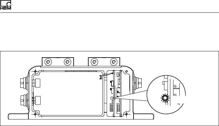
If you suspect that the transmission system is not
working properly, you can remove the stator cover and
test for correct functioning. If the LED is on, the rotor and
stator are properly aligned and there is no interference
with the transmission of measurement signals. When the
Settings
T10F A0608-14.0 HBM: public 53
calibration signal is triggered, the LED shines more
brightly.
Control LED
Fig. 9.4 Power transmission function test
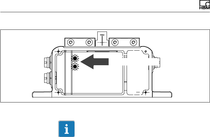
9.4.2 Aligning the speed module
When required, you can test the correct functioning of
the speed measuring system.
1. Remove the cover of the stator housing.
2. Turn the rotor by at least 2 min-1.
If both the control LEDs come on while you are turning
the rotor, the speed measuring system is properly
aligned and fully operational.
Settings
54 A0608-14.0 HBM: public T10F
Green control LEDs
Fig. 9.5 Control LEDs of the speed measuring system
Important
When closing the cover of the stator housing, make sure
that the internal connection cables are positioned in the
grooves provided and are not trapped.
Settings
T10F A0608-14.0 HBM: public 55
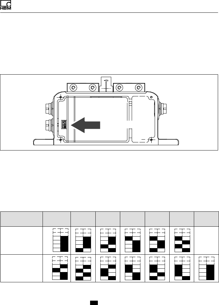
9.5 Setting the pulse count
The number of pulses per revolution of the rotor in the
speed module option can be adjusted by means of DIP
switches S1...S4.
Switches S1 ... S4
Fig. 9.6 Switches for setting the pulse count
Setting the pulse count
1. Remove the stator cover.
2. Use switches S1 ... S4 as per Tab. 7.1 to set the
required pulse count.
Pulses/
revolution1) 360 180 90 60 30 15 720
Rated torque
50 N⋅m...1 kN⋅m
S1
S4
Rated torque
2 N⋅m...10 kN⋅m
S1
S4
1) Factory setting with option 4
Fig. 9.7 Switch settings for the pulse count
( ¢ switch lever)
Settings
56 A0608-14.0 HBM: public T10F
9.6 Vibration suppression (hysteresis)
Low rotation speeds and higher relative vibrations
between the rotor and the stator can cause disturbance
signals that reverse the direction of rotation. Electronic
suppression (hysteresis) to eliminate these disturbances
is connected at the factory. Disturbances caused by the
radial stator vibration amplitude and by the torsional
vibration of the rotor are suppressed.
On Off
S5
Switch S5
Hysteresis
Fig. 9.8 Switch for switching off hysteresis
9.7 Form of speed output signal
In the factory setting, two 90_ phase‐offset speed signals
(5 V symmetrical, complementary RS-422 signals) are
available at the speed output (connector 2). You can
double the pulse count set in each case by moving
switch S6 to the “On" position. Pin 3 then outputs the
direction of rotation as a static direction of rotation signal
(pin 3 = +5 V, pin 7 = 0 V compared to pin 8), if the shaft
turns in the direction of the arrow). At a speed of 0 min-1,
the direction of rotation signal has the last measured
value.
Settings
T10F A0608-14.0 HBM: public 57
Direction of
rotation arrow
Fig. 9.9 Direction of rotation arrow on the head of the sensor
On Off
S6
Switch S6
Doubling the pulses
Fig. 9.10 Switch for doubling the pulses
Settings
58 A0608-14.0 HBM: public T10F
9.8 Type of speed output signal
You can use switch S7 to change the symmetrical 5 V
output signal (factory setting) to an asymmetrical signal
of 0 V ... 5 V.
Switch S7
asymmetricalsymmetrical
Pos.1
Pos.2
Fig. 9.11 Switch S7; symmetrical/asymmetrical output signal

Loading capacity
T10F A0608-14.0 HBM: public 59
10 Loading capacity
Nominal torque can be exceeded statically up to the limit
torque. If the nominal torque is exceeded, additional
irregular loading is not permissible. This includes
longitudinal forces, lateral forces and bending moments.
Limit values can be found in chapter 14 “Specifications”,
on page 70.
10.1 Measuring dynamic torque
The torque flanges can be used to measure static and
dynamic torques. The following rule applies to the
measurement of dynamic torque:
SThe T10F calibration made for static measurements is
also valid for dynamic torque measurements.
SThe natural frequency f0 for the mechanical
measuring system depends on the moments of inertia
J1 and J2 of the connected rotating masses and the
T10F torsional stiffness.
Use the equation below to approximately determine the
natural frequency f0 of the mechanical measuring
arrangement:
f0+1
2p· c
T·ǒ1
J1
)1
J2Ǔ
Ǹf0= natural frequency in Hz
J1, J2= mass moment of inertia in kg⋅m2
cT= torsional stiffness in N⋅m/rad
SThe oscillation width (peak‐to‐peak) can be max. 160
% (for nominal (rated) torques 50 N@m=320 %, 10
kN@m=120%) of the nominal (rated) torque
designated for the T10F, even under alternating load.
The vibration bandwidth must fall within the loading
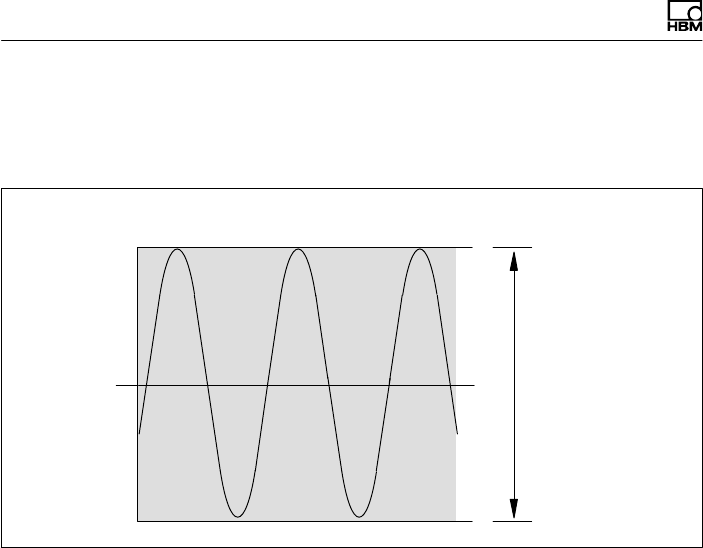
Loading capacity
60 A0608-14.0 HBM: public T10F
bandwidth specified by -Mnom and +Mnom (at 50 N@m:
-2@Mnom ... +2@Mnom). The same also applies to
transient resonance points.
+Mnom100 %
-Mnom 100 %
0
Nominal (rated) torque Mnom as a %
160 %
(320 %, 120 %) Mnom
vibration bandwidth
Fig. 10.1 Permissible dynamic loading
Maintenance
T10F A0608-14.0 HBM: public 61
11 Maintenance
Torque measurement flanges are maintenance‐free.
11.1 Speed module maintenance
During operation and depending on the ambient
conditions, the slotted disc of the rotor and the
associated stator sensor optics can get dusty. This will
become noticeable when the polarity of the display
changes. Should this occur, the sensor and the slotted
disc must be cleaned.
1. Use compressed air (up to 6 bar) to clean the slotted
disc.
2. Carefully clean the optical system of the sensor with a
dry cotton bud or one soaked with pure spirit. Do not
use any other solvent!
Fig. 11.1 Cleaning points on the speed sensor
Dimensions
62 A0608-14.0 HBM: public T10F
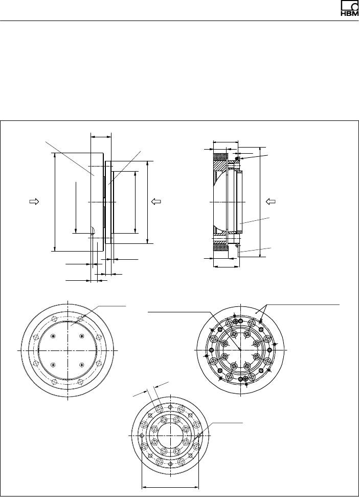
12 Dimensions
12.1 Rotor dimensions
8 x Øds
8 x Y
xs
YXN
3
2.5
b3
ØdF
Ødza
Ødzi
ØdA
b2b4
0.3
Ødz
ØdL
ØdB
b2*
Flange with installed slotted disc for speed measurement
Screw for fastening the
slotted disc with slotted
disc turned in the cutting
plane
Slotted disc
Intermediate flange only
with 50 N⋅m, 100 N⋅m
Measuring
body Adapter flange
xs = measuring
plane (center of
the application
point)
View X
View Z
Customer installation and
fastening of the slotted
screw
Centering point for
aligning the speed
measuring system
View Y
b1*
b1
Dimensions without tolerances
as per DIN ISO 2768-mK

Dimensions
T10F A0608-14.0 HBM: public 63
Measur
ing
range
Dimensions (in mm; 1 mm = 0.03937 inches)
b1b1* b2b2* b3b4Ø
dA
Ø
dB
Ø
dF
Ø
dL
Ø
dZ
Ødza
g5
Ødzi
H6
ØdsY Xs
50 N⋅m 15.5 17.5 25 31.5 7.5 29.5 117 87 100 11 131 75 75 6.4 M6 13
100 N⋅m 15.5 17.5 25 31.5 7.5 29.5 117 87 100 11 131 75 75 6.4 M6 13
200 N⋅m 17.5 17.5 30.5 30.5 11 29.5 137 105 121 14 151 90 90 8.4 M8 14
500 N⋅m 20.5 20.5 40.5 40.5 18 33 173 133 156 20 187 110 110 13 M12 15.5
1 kN⋅m20.5 20.5 40.5 40.5 18 33 173 133 156 20 187 110 110 13 M12 15.5
2 kN⋅m22.5 22.5 42.5 42.5 18 35 207 165 191 24 221 140 140 15 M14 16.5
3 kN⋅m27.0 22.5 55 55 26 35 207 165 191 24 221 140 140 15 M14 18.8
5 kN⋅m28.5 28.5 64 64 33.5 41 254 206 238 30 269 174 174 19 M18 19.5
10 kN⋅m 33.5 28.5 69 69 33.5 41 254 206 238 30 269 174 174 19 M18 22.5
Dimensions
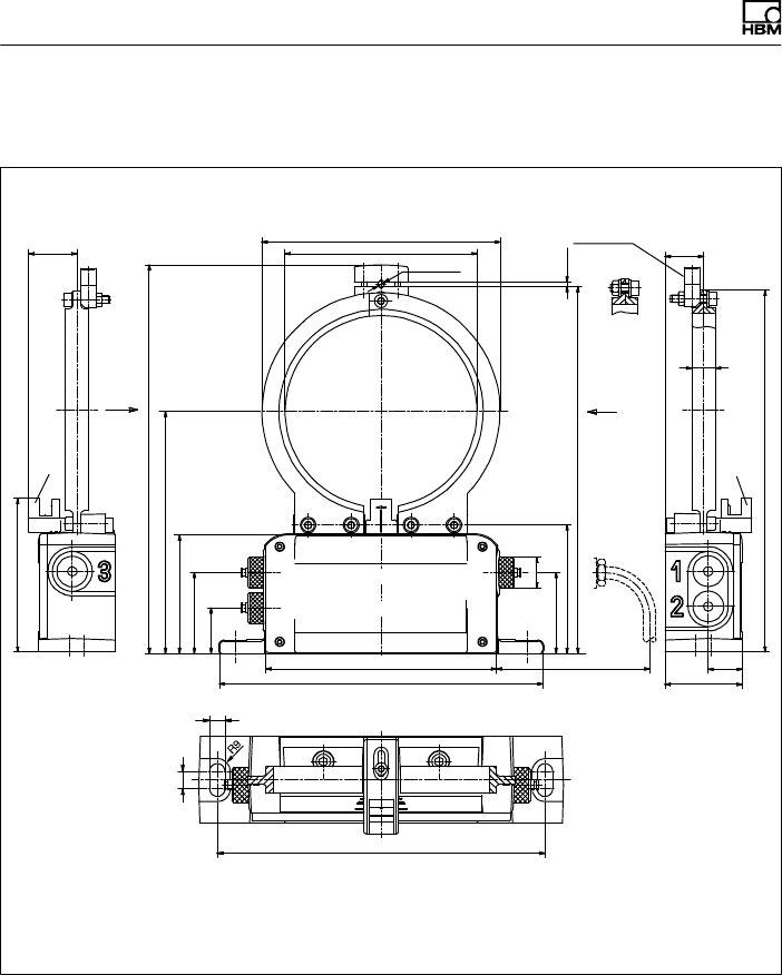
64 A0608-14.0 HBM: public T10F
12.2 Stator dimensions
100
H3 max.
H2
h
∅20
max. ∅4
∅d∅D
**
l
**
50
22
H1
25
Side view Y
approx. 3
Clamp fixture
not mounted
as standard! Side view X
Standard
screw
fitting
Connector
3***
Connector 1
Top view
*Space for connection cable with connector
** Only for speed measuring system option
*** Does not apply to version KF1
10
190
9
Accuracy of the cast base sizes
as per DIN 1688-GTA 14/5
b
Y
X
210 +2
150 +2
77
52.5
29.5
83.5
52.5
Connector 2**
approx. 100*

Dimensions
T10F A0608-14.0 HBM: public 65
Measuring
range
Dimensions (in mm; 1 mm = 0.03937 inches)
bjdjD H1 H2 H3 h l
50 N⋅m 15.5 125 155 235 239 253 157.5 31.5
100 N⋅m 15.5 125 155 235 239 253 157.5 31.5
200 N⋅m 17.5 145 175 255 259 273 167.5 31.5
500 N⋅m 20.5 181 211 291 295 309 185.5 33.5
1 kN⋅m20.5 181 211 291 295 309 185.5 33.5
2 kN⋅m22.5 215 245 325 329 343 202.5 34.5
3 kN⋅m22.5 215 245 325 329 343 202.5 34.5
5 kN⋅m28.5 262 292 373 377 391 226.5 37.5
10 kN⋅m 28.5 262 292 373 377 391 226.5 37.5
Dimensions
66 A0608-14.0 HBM: public T10F
12.3 Mounting dimensions
Adapter
flange
Stator
identification
plate
Measuring body
Rotor
identification
plate
b
2
aa
a
x

Dimensions
T10F A0608-14.0 HBM: public 67
Mounting dimensions
Measuring
range
Dim. "m"
(mm)
Area free of metal parts1)
(mm)
a x
50 N⋅m 16.25 20 29.5
100 N⋅m
200 N⋅m 21.75 20 29
500 N⋅m 30.25 20 29.5
1 kN⋅m 30.25 20 29.5
2 kN⋅m 31.25 25 29
3 kN⋅m 43.75 25 29
5 kN⋅m 49.75 35 29.5
10 kN⋅m54.75 35 29.5
1) Support with metal rod is permissible with the recommended
dimensions
Order numbers, accessories
68 A0608-14.0 HBM: public T10F
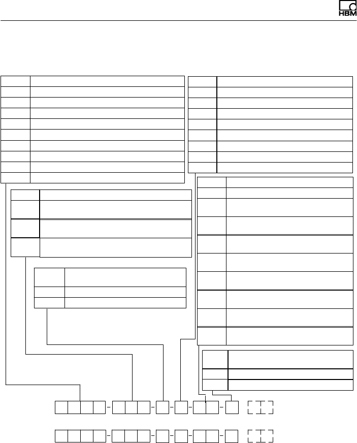
13 Order numbers, accessories
Order number:
Ordering example:
YSF 1 0500Q
Code Option 2: Electrical configuration
SF1 Output signal 10 kHz "5 kHz,
supply voltage 18 ... 30 V DC
SU2 Output signal 10 kHz "5 kHz and "10 V,
supply voltage 18 - 30 V DC
Code Option 6: Mounted couplings
MODULFLEX4)
NWithout coupling
With coupling
Code Option 3: Linearity deviation
including hysteresis
S< ±0.1
G< ±0.051
S
Code Option 5: Connection cable
V1 Torque connection cable for KF1,
423 free ends, 6m
V2*) Torque connection cable for KF1,
423 free ends, max. 80 m
V3 Torque connection cable for KF1,
423 MS3106PEMV, 6m
V4*) Torque connection cable for KF1,
423 MS3106PEMV, max. 80 m
V0 Without connection cable
Code Option 4: Speed measuring system 2)
1360 Pulses/revolution
2180 Pulses/revolution
390 Pulses/revolution
460 Pulses/revolution
530 Pulses/revolution
615 Pulses/revolution
7720 Pulses/revolution 3)
0Without the speed measuring system
V5
m5)
KF1 Output signal 10 kHz "5 kHz,
excitation voltage 14 kHz / 54 V; square wave
V5 Torque connection cable for
SF1/SU2, 423 DSub 15P, 6m
V6*) Torque conn. cable for SF1/SU2,
423 D-Sub 15P, max. 50 m
W1 Torque and speed, one cable each,
423 D‐Sub 15P, 6m
W2*) Torque and speed, one cable each,
423 D‐Sub 15P, max. 50 m
m5)
Y
K−T10F −
K−T10F −
Code Option 1: Measuring range
100Q 100 N⋅m
200Q 200 N⋅m
500Q 500 N⋅m
001R 1 kN⋅m
002R 2 kN⋅m
003R 3 kN⋅m
005R 5 kN⋅m
050Q 50 N⋅m
010R 10 kN⋅m
1) For voltage output <±0.07
2) For option 2, code SF1, SU2 only
3) Only with option 1, code 002R,
003R, 005R, 010R
4) Specifications, see data sheet B0120‐x.x
5) With selections V2, V4, V6 and W2, please
specify required length of cable.

Order numbers, accessories
T10F A0608-14.0 HBM: public 69
Accessories, to be ordered separately
Order No.
Cable socket 423G-7S, 7‐pin, straight cable entry, for torque output
(connectors 1, 3)
3-3101.0247
Cable socket 423W-7S, 7‐pin, 90° cable entry, for torque output
(connectors 1, 3)
3-3312.0281
Cable socket 423G-8S, 8‐pin, straight cable entry, for speed output
(connector 2),
3-3312.0120
Cable socket 423W-8S, 8‐pin, 90° cable entry, for speed output
(connector 2)
3-3312.0282
Kab8/00-2/2/2 by the meter 4-3301.0071

Specifications
70 A0608-14.0 HBM: public T10F
14 Specifications
Type T10F
Accuracy class 0.1
Torque measuring system
Nominal (rated) torque
Mnom
NVm 50 100 200 500 1k 2k 3k 5k 10k
Nominal (rated) sensitivity
(nominal (rated) signal range
between torque = zero and
nominal (rated) torque)
Frequency output kHz 5
Voltage output V 10
Sensitivity tolerance
(deviation of actual output
quantity at Mnom from
nominal (rated) signal range)
Frequency output %"0.1
Voltage output %"0.2
Output signal at torque =
zero
Frequency output kHz 10
Voltage output V 0
Nominal output signal
Frequency output
at positive nominal (rated)
torque kHz 15 (5 V symmetrical1)/12 V asymmetrical2))
at negative nominal (rated)
torque kHz 5 (5 V symmetrical1)/12 V asymmetrical2))
Voltage output
at positive nominal (rated)
torque V +10
at negative nominal (rated)
torque V ‐10

Specifications
T10F A0608-14.0 HBM: public 71
Nominal (rated) torque
Mnom
10k5k3k2k1k50020010050NVm
Load resistance
Frequency output kΩ ≥2
Voltage output kΩ ≥5
Longterm drift over 48 h
Voltage output mV ≤"3
Measurement frequency
range
Voltage output Hz 0 ... 1000 (-3 dB)
Group delay
Frequency output ms 0.15
Voltage output ms 0.9
Residual ripple
Voltage output %0.4 (peak‐to‐peak)
Temperature effect per 10
K in the nominal (rated)
temperature range
on the output signal, related
to the actual value of the
signal spread
Frequency output %<"0.1
Voltage output %< "0.2
on the zero signal, related to
the nominal (rated)
sensitivity
Frequency output % <±0.1 <"0.05
Voltage output % <±0.2 < "0.15
Power supply (version
KF1)
Excitation voltage (square
wave) V 54"5% (peak‐to‐peak)
Calibration signal triggering V80"5 %
Frequency kHz approx. 14
Max. current consumption A1 (peak‐to‐peak)

Specifications
72 A0608-14.0 HBM: public T10F
Nominal (rated) torque
Mnom
10k5k3k2k1k50020010050NVm
Preamplifier excitation
voltage V 0/0/+15
Preamplifier, max. current
consumption mA 0/0/+25
Power supply (version
SF1/SU2)
Nominal (rated) supply
voltage (separated extralow
voltage (SELV))
V (DC) 18 ... 30; asymmetrical
Current consumption in
measuring mode A< 0.9
Current consumption in
startup mode A< 2
Nominal (rated) power
consumption W< 12
Linearity deviation
including hysteresis,
relative to the nominal
(rated) sensitivity
Frequency output %<"0.1 (optional <"0.05)
Voltage output %<"0.1 (optional <"0.07)
Rel. standard deviation of
reproducibility
as per DIN 1319, relative to
the variation of the output
signal
%<"0.03
Calibration signal approx. 50% of Mnom;
more precise value on identification plate
Tolerance of the
calibration signal %< "0.05
Speed measuring system
Measurement system Optical, by means of infrared light and metallic slotted disc
Mechanical increments No. 360 720
Positional tolerance of the
increments mm "0.05
Slot width tolerance mm "0.05

Specifications
T10F A0608-14.0 HBM: public 73
Nominal (rated) torque
Mnom
10k5k3k2k1k50020010050NVm
Pulses per revolution
adjustable No. 360; 180; 90; 60; 30; 15 720; 360; 180; 90; 60;
30; 15
Output signal V5 symmetrical (complementary signals RS-422)
2 square‐wave signals, approx. 90_ phase‐shifted
Load resistance kΩ ≥2
Minimum rotational speed
for sufficient pulse
stability
min-1 2
Group delay µs< 5 typ. 2.2
Max. permissible axial
displacement of the rotor
to the stator mm "2
Max. permissible radial
shift of the rotor to the
stator mm "1
Hysteresis of reversal3)
in the case of relative
vibrations between the rotor
and the stator
Torsional vibration of the
rotor Degr. < approx. 2
Radial vibration
amplitude of the stator mm < approx. 2
Permitted degree of
pollution, in the optical path
of the optical sensor (lenses,
slotted disc)
%< 50
Protection against
ambient light By fork and infrared filter

Specifications
74 A0608-14.0 HBM: public T10F
Nominal (rated) torque
Mnom
10k5k3k2k1k50020010050NVm
General Information
EMC
Emission (per FCC 47
Part 15, Subpart C)
Immunity from
interference
(DIN EN50082-2)
Electromagnetic field
Housing V/m 10
Leads VPP 10
Magnetic field A/m 100
Burst kV 2/1
ESD kV 4/8
Interference emission
(EN55011; EN55022;
EN55014)
RFI voltage Class A
RFI power Class B
RFI field strength Class B
Degree of protection per
EN 60529 IP 54
Weight, approx.
Rotor kg 0.9 0.9 1.8 3.5 3.5 5.8 7.8 14.0 15.2
Rotor with speed measuring
system kg 1.1 1.1 1.8 3.5 3.5 5.9 7.9 14.1 15.3
Stator kg 1.1 1.1 1.2 1.2 1.2 1.3 1.3 1.4 1.4
Reference temperature °C+23
Nominal (rated) temp.
range °C+10...+60
Operating temperature
range °C‐10...+60
Storage temperature
range °C‐20...+70

Specifications
T10F A0608-14.0 HBM: public 75
Nominal (rated) torque
Mnom
10k5k3k2k1k50020010050NVm
Impact resistance, test
severity level according to
DIN IEC 68; Part 227; IEC
682271987
Number n 1000
Duration ms 3
Acceleration (half sine) m/s2650
Vibration resistance, test
severity level per
DIN IEC 68, Part 2-6:
IEC 68‐2‐6‐1982
Frequency range Hz 5...65
Duration h 1.5
Acceleration (amplitude) m/s250
Nominal speed (x1000) min-1 15 15 15 12 12 10 10 8 8
Load limits4)
Limit torque, related to
Mnom % 400 200 160
Breaking torque, related to
Mnom % >800 >400
>30
0
Longitudinal limit force kN 2 2 4 7 7 12 14 22 31
Lateral limit force kN 1 1 3 6 8 15 18 30 40
Bending limit moment N⋅m 70 70 140 500 500 1000 1600 2500 4000
Oscillation width per
DIN 50 100 (peaktopeak)5) kN⋅m 0.16 0.16 0.32 0.8 1.6 3.2 4.8 8.0 12.0
1) RS-422 complementary signals; factory settings version SF1/SU2
2) Factory settings version KF1 (changeover not possible)
3) Can be switched off
4) Each type of irregular stress (bending moment, lateral or longitudinal force, exceeding nominal
(rated) torque) can only be permitted up to its specified static load limit provided none of the others
can occur at the same time. If this condition is not met, the limit values must be reduced. If 30% of
the bending limit moment and lateral limit force occur at the same time, only 40% of the
longitudinal limit force is permissible and the nominal (rated) torque must not be exceeded. The
permissible bending moments, longitudinal forces and lateral forces can affect the measurement
result by approx. 1 % of the nominal (rated) torque.
5) It is permissible to exceed the nominal (rated) torque by 100% with T10F/50 N⋅m, but the nominal
torque may not be exceeded with T10F/100 N⋅m up to 10 kN⋅m.

Specifications
76 A0608-14.0 HBM: public T10F
Mechanical values 50 NVm ... 500 NVm
Nominal (rated) torque Mnom NVm 50 100 200 500
Torsional stiffness cTkN⋅m/ rad 160 160 430 1000
Torsion angle Mnom Degree 0.018 0.036 0.027 0.028
Maximum deflection at longitudinal force
limit mm < 0.03
Additional max. radial run‐out deviation at
lateral limit force mm < 0.01 < 0.02
Additional plane/parallel deviation at
bending moment limit mm < 0.2
Balance quality level per DIN ISO 1940 G 6.3
Max. limits for relative rotor vibration
displacement (peaktopeak)6)
Undulations in area of connection flange, based
on ISO 7919-3
Normal operation (continuous operation) µms(p*p) +9000
n
Ǹ(nin min*1)
Start and stop operation/resonance ranges
(temporary) µms(p*p) +13200
n
Ǹ(nin min*1)
Mass moment of inertia of the rotor
IV (around axis of rotation) x 10-3 kg⋅m21.3 1.3 3.4 13.2
IV with speed system x 10-3 kg⋅m21.7 1.7 3.5 13.2
Proportional mass moment of inertia
(measuring body side) % 51 51 44 39
Proportional mass moment of inertia
with speed measuring system (measuring
body side)
% 40 40 43 39
Max. permissible static eccentricity of the
rotor (radially)7) mm "2
Perm. axial displacement
between rotor and stator7) mm "2"3
6) The influence of radial run‐out deviations, eccentricity, defects of form, notches, marks, local
residual magnetism, structural variations or material anomalies needs to be taken into account
and isolated from the actual wave oscillation.
7) Refer to limited values for speed measuring system

Specifications
T10F A0608-14.0 HBM: public 77
Mechanical values 1 kNVm ... 10 kNVm
Nominal (rated) torque Mnom NVm1 k 2 k 3 k 5 k 10 k
Torsional stiffness cTkN⋅m/ rad 1800 3300 5100 9900 15000
Torsion angle Mnom Degree 0.032 0.034 0.034 0.029 0.038
Maximum deflection at longitudinal
force limit mm < 0.03
Additional max. radial run‐out
deviation at lateral limit force mm < 0.02 < 0.03
Additional plane/parallel deviation at
bending moment limit mm < 0.2
Balance quality level per DIN ISO 1940 G 6.3
Max. limits for relative rotor vibration
displacement (peaktopeak)8)
Undulations in area of connection flange,
based on ISO 7919-3
Normal operation (continuous
operation) µms(p*p) +9000
n
Ǹ(nin min*1)
Start and stop operation/resonance
ranges (temporary) µm s(p*p) +13200
n
Ǹ(nin min*1)
Mass moment of inertia of the rotor
IV (around axis of rotation) x 10-3 kg⋅m213.2 29.6 41 110 120
IV with speed system x 10-3 kg⋅m213.2 29.6 41 110 120
Proportional mass moment of inertia
(measuring body side) % 39 38 33 31 33
Proportional mass moment of inertia
with speed measuring system
(measuring body side)
% 39 38 33 31 33
Max. permissible static eccentricity of
the rotor (radially)9) mm "2
Perm. axial displacement
between rotor and housing9) mm "3
8) The influence of radial run‐out deviations, eccentricity, defects of form, notches, marks, local
residual magnetism, structural variations or material anomalies needs to be taken into account
and isolated from the actual wave oscillation.
9) Refer to limited values for speed measuring system
Specifications
78 A0608-14.0 HBM: public T10F
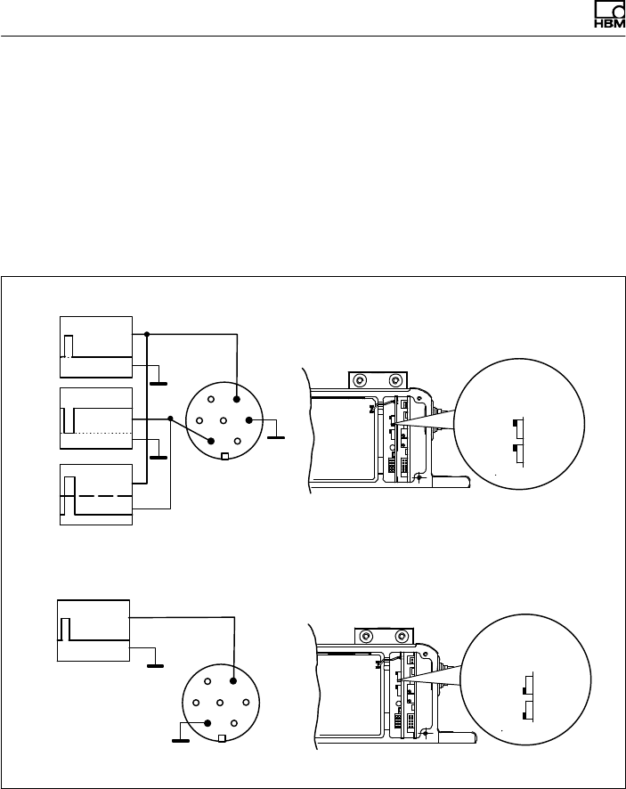
15 Supplementary technical information
15.1 Output signals
15.1.1 Output MD torque (connector 1)
1
4
5
0 V
0 V
5 V
5 V
10 Vpp Connector 1
0 V
12 V
1
4
Connector 1
Symmetrical output signals (factory settings)
Asymmetrical output signal
Differential inputs
5 V
symmetrical
Pos.2 S1
S2
Pos.1
12 V
asymmetrical
S1
S2
0 V
Specifications
T10F A0608-14.0 HBM: public 79
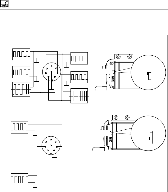
15.1.2 Output N: Speed (connector 2)
5 V
10 VPP
Symmetrical output signals (factory settings)
Asymmetrical output signals
0V
5V
Connector 2
0 V
0 V
5 V
Connector 2
Differential
inputs
7
38
6
1
4
2
5
7
38
6
4
2
5
1
Switch S7
symmetrical
Pos.2
Switch S7
asymmetrical
Pos.1
0 V
5 V
0 V
0 V
5 V
0 V
10VPP
5 V
Specifications
80 A0608-14.0 HBM: public T10F
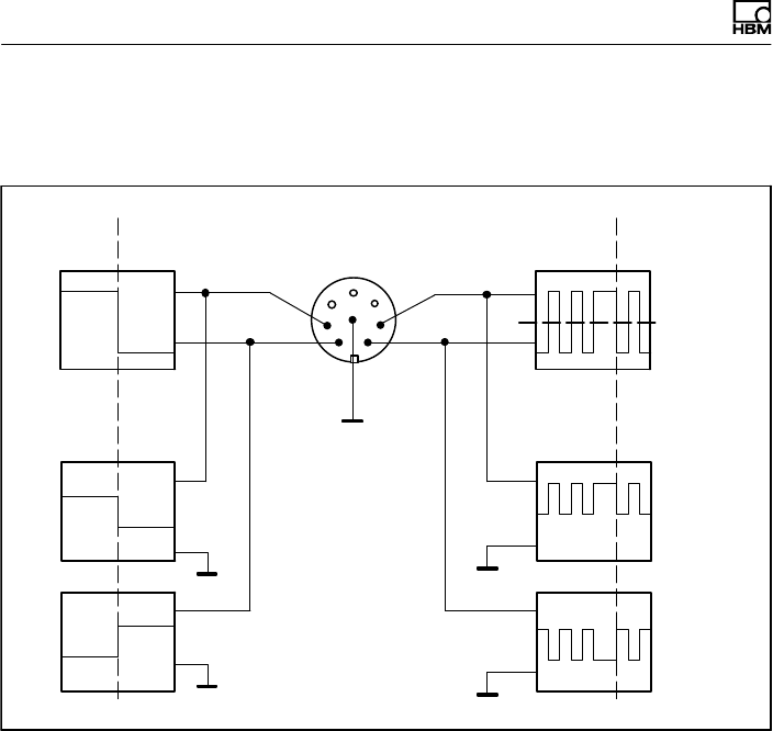
15.1.3 Connector 2, double frequency, stat. direction
of rotation signal
5 V
5 V 0 V
Connector 2
7
38
6
1
4
2
5
5 V
0 V
0 V
0 V
0 V
5 V
Direction of
rotation in
direction of the
arrow
Direction of
rotation against
direction of the
arrow
10 Vcc
10 Vcc
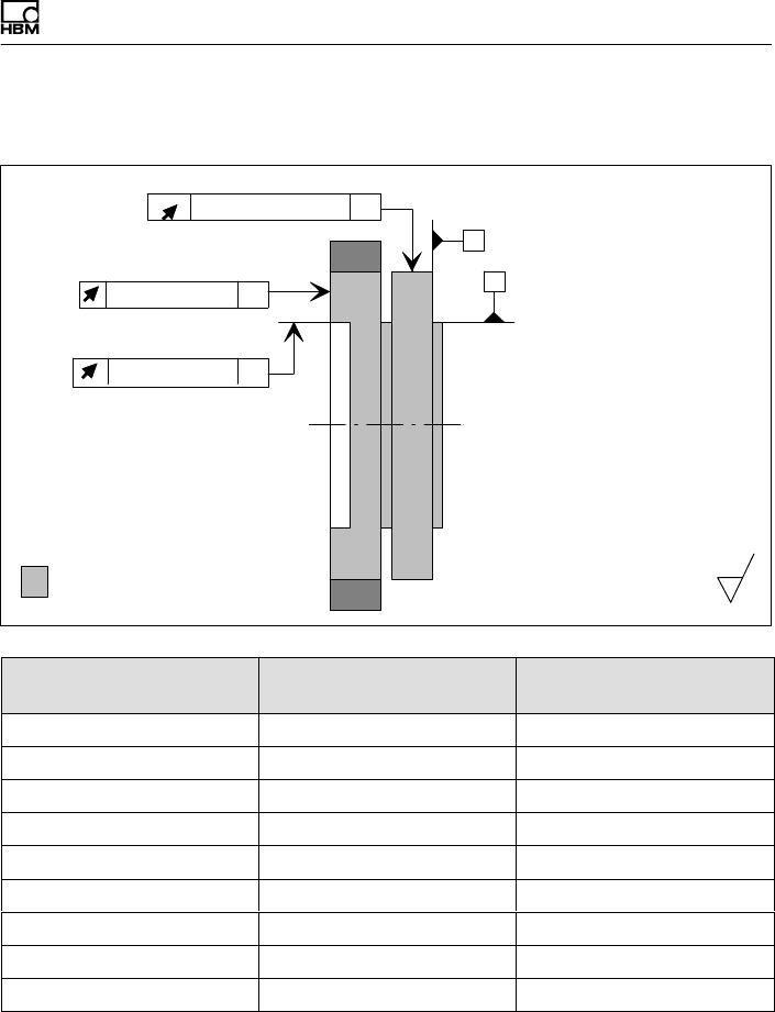
Specifications
T10F A0608-14.0 HBM: public 81
15.2 Axial and radial run‐out tolerances
Internal centering
Outside diameter
A
Axial runout
B
Radial run-out AB
Radial run-out AB
Adapter flange
Measuring body
Hardness 46 ... 54 HRC
Surface quality of the run−out
and concentric surfaces (A, B
and AB)
0.8
AB
Measuring range Axial runout tolerance
(mm)
Radial run‐out tolerance
(mm)
50 N⋅m 0.02 0.02
100 N⋅m 0.02 0.02
200 N⋅m 0.02 0.02
500 N⋅m 0.02 0.02
1 kN⋅m 0.02 0.02
2 kN⋅m 0.04 0.04
3 kN⋅m 0.04 0.04
5 kN⋅m 0.04 0.04
10 kN⋅m0.04 0.04

Specifications
82 A0608-14.0 HBM: public T10F
15.3 Additional mechanical data
Nominal (rated) torque
Mnom
NVm 50 100 200 500 1 k 2 k 3 k 5 k 10 k
Mechanical values
Stiffness in the axial
direction ca
kN/mm 90 90 190 410 430 500 900 1200 2100
Stiffness in the radial
direction cr kN/mm 200 200 280 430 440 750 820 1000 1430
Stiffness during the
bending moment
around a radial axis cb
kN⋅m/
deg. 0.9 0.9 2.7 8.8 9.1 18.3 37.5 69.0 142
kN⋅m/
rad 51 51 155 510 520 1050 2150 3950 8000

Specifications
T10F A0608-14.0 HBM: public 83

www.hbm.com
HBM Test and Measurement
Tel. +49 6151 803-0
Fax +49 6151 803-9100
info@hbm.com
measure and predict with confidence
A0608-14.0 7-2001.1510 HBM: public