Hottinger Bruel and Kjaer T12S4 T12-S4 Torquemeter User Manual A1979 100
Hottinger Baldwin Messtechnik GmbH T12-S4 Torquemeter A1979 100
User Manual
A1979−10.0 en
Digital
Torque Transducer
T12
Mounting Instructions

3
T12
A1979−10.0 en HBM
Contents Page
Contents
Safety instructions 5..............................................
1 Markings used 9...............................................
1.1 Symbols on the transducer and / or Stator 9...................
1.2 The markings used in this document 10........................
2 Scope of supply 11.............................................
3 Operation 11...................................................
4 Application 12..................................................
5 Signal flow 13..................................................
6 Structure and mode of operation 14..............................
7 Mechanical installation 16.......................................
7.1 Important precautions during installation 16....................
7.2 Conditions on site 17........................................
7.3 Mounting position 17........................................
7.4 Installing the slotted disc (rotational speed measuring system
only) 18...................................................
7.5 Installing the rotor 19........................................
7.6 Fitting the protection against contact (option) 21................
7.7 Installing the stator 27.......................................
7.7.1 Preparing with the mounting kit (included among the items
supplied) 28..........................................
7.7.2 Aligning the stator 30..................................
7.7.3 Stator installation over the protection against contact
(option) 32...........................................
7.8 Optical rotational speed/angle of rotation measuring system
(option) 33.................................................
7.8.1 Axial alignment 33....................................
7.8.2 Radial alignment 34...................................
8 LED status display 36...........................................
8.1 Measuring mode operation 36................................
8.2 Rotor clearance setting mode operation 36.....................
8.3 Rotational speed measuring system setting mode operation 36...
9 Electrical connection 37.........................................
9.1 General information 37......................................
9.2 Shielding design 39.........................................

T12
4
A1979−10.0 enHBM
9.3 Connector pin assignment 39................................
9.4 Supply voltage 43..........................................
10 Shunt signal 45.................................................
11 Load-carrying capacity 46.......................................
12 TEDS 47.......................................................
13 Maintenance 54.................................................
14 Waste disposal and environmental protection 55..................
15 Specifications 56...............................................
15.1 Nominal (rated) torque 100 Nm to 1 kNm56...................
15.2 Nominal (rated) torque 2 kNm to 10 kNm63...................
16 Dimensions 70.................................................
16.1 Rotor 100 Nm to 200 Nm70................................
16.2 Rotor 500 Nm to 10 kNm71................................
16.3 Stator 100 Nm to 200 Nm with rot.speed meas. system 72......
16.4 Stator 100 Nm to 200 Nm with rot. speed meas. system 73.....
16.5 Stator 100 Nm to 10 kNm with rot. speed meas. system 74.....
16.6 Stator 100 Nm to 200 Nm with prot. against contact 75.........
16.7 Stator 100 Nm to 200 Nm with prot. against contact 76.........
16.8 Stator 500 Nm to 1 kNm with prot. against contact 77..........
16.9 Stator 2 kNm to 10 kNm with prot. against contact 78...........
16.9.1 Protection against contact plates 100 Nm to 200 Nm79...
16.9.2 Protection against contact plates 500 Nm to 10 kNm79...
16.10 Mounting dimensions 80.....................................
17 Supplementary technical information 81..........................
18 Condition at the time of delivery 82...............................
19 Ordering numbers 87...........................................
20 Accessories 88.................................................

5
T12
A1979−10.0 en HBM
Safety instructions
FCC Compliance & Advisory Statement for Option 7, Code U
This device complies with Part 15 of the FCC Rules. Operation is subject to
the following two conditions: (1) this device may not cause harmful interfer-
ence, and (2) this device must accept any interference received, including in-
terference that may cause undesired operation.
The FCC identifier or the unique identifier, as appropriate, must be displayed
on the device.
Model FCC ID IC
T12, 100 Nm, 200 Nm 2ADAT−T12S2 12438A−T12S2
T12, 500 Nm, 1 kNm 2ADAT−T12S3 12438A−T12S3
T12, 2 kNm, 3 kNm 2ADAT−T12S4 12438A−T12S4
T12, 5 kNm 2ADAT−T12S5 12438A−T12S5
T12, 10 kNm 2ADAT−T12S6 12438A−T12S6
The FCC ID number in dependence of measuring range: label example only
on the Stator FCC ID and IC number range.
Label example with FCC ID and IC number. Location on the stator of the
device.
FCC ID: 2ADAT-T12S2
IC: 12438AT12S2
This device complies with part 15 of the FCC Rules. Operation is subject to the following
two conditions: (1) This device may not cause harmful interference, and (2) this device
must accept any interference received, including interference that may cause undesired
operation.
Fig 1.1: Example of the label
Industry Canada for Option 7, Code U
IC: 12483A−T12S2
This device complies with Industry Canada standard RSS210.
This device complies with Industry Canada license−exempt RSS standard(s).
Operation is subject to the following two conditions: (1) this device may not
cause interference, and (2) this device must accept any interference, including
interference that may cause undesired operation of the device.
Cet appareil est conforme aux norme RSS210 d’Industrie Canada.

T12
6
A1979−10.0 enHBM
Cet appareil est conforme aux normes d’exemption de licence RSS d’Industry
Canada. Son fonctionnement est soumis aux deux conditions suivantes : (1)
cet appareil ne doit pas causer d’interférence et (2) cet appareil doit accepter
toute interférence, notamment les interférences qui peuvent affecter son
fonctionnement.
NOTE
Any changes or modification not expressly approved by the party responsible
for compliance could void the user’s authority to operate the device. Where
specified additional components or accessories elsewhere defined to be used
with the installation of the product, they must be used in order to ensure com-
pliance with FCC regulations.
Appropriate use
The T12 torque flange is used exclusively for torque, angle of rotation and
power measurement tasks within the load limits stipulated in the
specifications. Any other use is not appropriate.
Stator operation is only permitted when the rotor is installed.
The torque flange may only be installed by qualified personnel in compliance
with the specifications and with the safety requirements and regulations of
these mounting instructions. It is also essential to observe the applicable legal
and safety regulations for the application concerned. The same applies to the
use of accessories.
The torque flange is not intended for use as a safety component. Please also
refer to the “Additional safety precautions” section. Proper and safe operation
requires proper transportation, correct storage, siting and mounting, and
careful operation.
Load carrying capacity limits
The data in the technical data sheets must be complied with when using the
torque flange. In particular, the respective maximum loads specified must
never be exceeded. For example, the values stated in the specifications must
not be exceeded for
limit torque,
longitudinal limit force, lateral limit force or limit bending moment,
torque oscillation width,
breaking torque,
temperature limits,
the limits of the electrical load-carrying capacity.

7
T12
A1979−10.0 en HBM
Use as a machine element
The torque flange can be used as a machine element. When used in this
manner, it must be noted that, to favor greater sensitivity, the transducer is not
designed with the safety factors usual in mechanical engineering. Please refer
here to the section “Load carrying capacity limits” and to the specifications.
Accident prevention
According to the prevailing accident prevention regulations, once the
transducers have been mounted, a covering agent or cladding has to be fitted
as follows:
The covering agent or cladding must not be free to rotate.
The covering agent or cladding should prevent squeezing or shearing and
provide protection against parts that might come loose.
Covering agents and cladding must be positioned at a suitable distance or
be so arranged that there is no access to any moving parts within.
Covering agents and cladding must still be attached, even if the moving
parts of the torque flange are installed outside people’s movement and
working range.
The only permitted exceptions to the above requirements are if the torque
flange is already fully protected by the design of the machine or by existing
safety precautions.
Additional safety precautions
The torque flange cannot (as a passive transducer) implement any
(safety-relevant) cutoffs. This requires additional components and
constructive measures, for which the installer and operator of the plant is
responsible. The electronics conditioning the measurement signal should be
designed so that measurement signal failure does not subsequently cause
damage.
The scope of supply and performance of the transducer covers only a small
area of torque measurement technology. In addition, equipment planners,
installers and operators should plan, implement and respond to safety
engineering considerations in such a way as to minimize residual dangers.
Pertinent national and local regulations must be complied with.
General dangers of failing to follow the safety instructions
The torque flange corresponds to the state of the art and is reliable.
Transducers can give rise to residual dangers if they are incorrectly operated
or inappropriately mounted, installed and operated by untrained personnel.
Every person involved with siting, starting-up, operating or repairing a torque
flange must have read and understood the mounting instructions and in
particular the technical safety instructions. The transducers can be damaged

T12
8
A1979−10.0 enHBM
or destroyed by non-designated use of the transducer or by non-compliance
with the mounting and operating instructions, these safety instructions or any
other applicable safety regulations (BG safety and accident prevention
regulations), when using the transducers. Transducers can break, particularly
in the case of overloading. The breakage of a transducer can also cause
damage to property or injury to persons in the vicinity of the transducer.
If the torque flange is not used according to the designated use, or if the
safety instructions or specifications in the mounting and operating instructions
are ignored, it is also possible that the transducer may fail or malfunction, with
the result that persons or property may be adversely affected (due to the
torques acting on or being monitored by the torque flange).
Conversions and modifications
The transducer must not be modified from the design or safety engineering
point of view except with our express agreement. Any modification shall
exclude all liability on our part for any damage resulting therefrom.
Selling on
If the torque flange is sold on, these mounting instructions must be included
with the torque flange.
Qualified personnel
Qualified personnel means persons entrusted with siting, mounting, starting
up and operating the product, who possess the appropriate qualifications for
their function.
This includes people who meet at least one of the three following
requirements:
−Knowledge of the safety concepts of automation technology is a
requirement and as project personnel, you must be familiar with these
concepts.
−As automation plant operating personnel, you have been instructed how to
handle the machinery. You are familiar with the operation of the equipment
and technologies described in this documentation.
−As system startup engineers or service engineers, you have successfully
completed the training to qualify you to repair the automation systems. You
are also authorized to ground and label circuits and equipment and place
them in operation in accordance with safety engineering standards.
9
T12
A1979−10.0 en HBM
1 Markings used
1.1 Symbols on the transducer and / or Stator
Symbol:
Meaning: Read and note the data in this manual
Symbol:
Meaning: CE mark
The CE mark enables the manufacturer to guarantee that the product
complies with the requirements of the relevant EC directives (the Declaration
of Conformity can be found on the HBM website at www.hbm.com under
HBMdoc).
Lable example with FCC ID and IC number. Location on the stator of the
device.
FCC ID: 2ADAT-T12S2
IC: 12438AT12S2
This device complies with part 15 of the FCC Rules. Operation is subject to the following
two conditions: (1) This device may not cause harmful interference, and (2) this device
must accept any interference received, including interference that may cause undesired
operation.
Symbol:
Meaning: Statutory waste disposal mark
The electrical and electronic devices that bear this symbol are subject to the
European waste electrical and electronic equipment directive 2002/96/EC.
The symbol indicates that, in accordance with national and local
environmental protection and material recovery and recycling regulations, old
devices that can no longer be used must be disposed of separately and not
with normal household garbage, see also Chapter 14, page 55.
T12
10
A1979−10.0 enHBM
1.2 The markings used in this document
Important instructions for your safety are specifically identified. It is essential
to follow these instructions in order to prevent accidents and damage to
property.
Symbol Significance
WARNING
This marking warns of a potentially
dangerous situation in which failure to
comply with safety requirements can result
in death or serious physical injury.
CAUTION
This marking warns of a potentially
dangerous situation in which failure to
comply with safety requirements can result
in slight or moderate physical injury.
NOTE
This marking draws your attention to a
situation in which failure to comply with
safety requirements can lead to damage to
property.
Important
This marking draws your attention to
important information about the product or
about handling the product.
Tip This marking indicates application tips or
other information that is useful to you.
This marking draws your attention to
information about the product or about
handling the product.
Emphasis Italics are used to emphasize and highlight
texts.

11
T12
A1979−10.0 en HBM
2 Scope of supply
Digital torque transducer (rotor and stator)
T12 mounting instructions
T12 system CD
Mounting kit
Manufacturing certificate
Tape wound core (toroidal core) only with Option 9, Code U
Tape wound core (toroidal core) only with Option 9, Code U
Optional:
−A rotational speed measuring system, comprising an optical rotational
speed sensor and a rotational speed kit (slotted disc, screwdriver,
threadlocker, screws)
−Protection against contact
−A mounted coupling
3 Operation
The supplied T12 system CD contains the “T12 Assistant” control software.
You can use this software to:
monitor the correct installation of the torque transducer
set the signal conditioning (zero balance, filters, scaling)
protect your settings or load the factory settings
display and evaluate the measured values
Instructions for installing the T12 Assistant on your PC can be found in the
“T12 Assistant Control Software” Quick Start Guide (pdf file on the T12
System CD and included in the “Setup Toolkit for T12” accessory).
Instructions for operating the T12 Assistant can be found in the program’s
online Help, which is called with function key F1 or via the menu bar.
Instructions for connecting to fieldbus systems can be found in the “T12 CAN
Bus/PROFIBUS” operating manual (pdf file on the T12 system CD).

T12
12
A1979−10.0 enHBM
4 Application
The T12 digital torque transducer acquires static and dynamic torque at
stationary or rotating shafts, determines the rotational speed or angle of
rotation while specifying the direction of rotation, and calculates the power. It
is designed for:
highly dynamic torque measurements when testing the power and
functionality of engines and compound sets
high-resolution rotational speed and angle of rotation measurements
fast, dynamic power measurements on engine and transmission test rigs
and roll test stands
Designed to work without bearings and with contactless digital signal
transmission, the torque measuring system is maintenance-free.
The torque transducer is supplied for nominal (rated) torques of 100 Nm to
10 kNm. Depending on the nominal (rated) torque, maximum rotational
speeds of up to 18 000 rpm are permissible.
The T12 torque transducer is reliably protected against electromagnetic
interference. It has been tested according to harmonized European standards
and complies with US and Canadian standards. The product carries the CE
mark and / or FCC label.
13
T12
A1979−10.0 en HBM
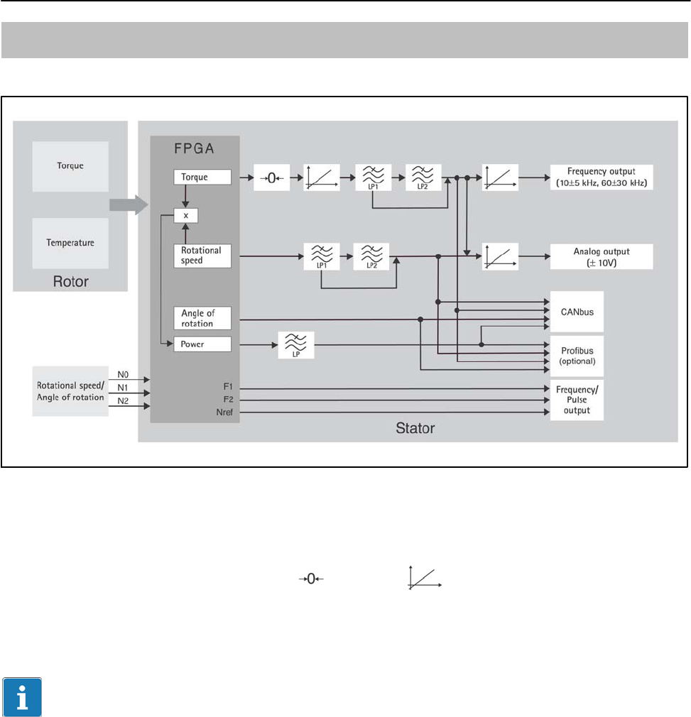
5 Signal flow
Low pass LP1: 0.05 Hz to 4000 Hz
Low pass LP2: 0.05 Hz to 100 Hz
Low pass LP: 0.1 Hz to 80 Hz
Fig. 4.1: Signal flow diagram
The torque and the temperature signal are already digitized in the rotor and
transmission is noise-free.
The torque signal can be zeroed , scaled (2-point scaling) and
filtered via two low passes (LP1 and LP2). A further scaling of the frequency
output and the analog output is then possible.
Important
Scaling at position (see Fig. 4.1) changes the internal calibration of the
torque transducer.
The rotational speed signal can be filtered and also scaled for analog output.
The angle of rotation signal, the power signal (low-pass filter LP) and the
temperature signal are only available on fieldbuses.
The torque signal and the rotational speed signal can be filtered via two low
passes connected in series, with filter outputs also being available separately.
The scaled, unfiltered torque signal is used to calculate power. The resultant,
highly-dynamically calculated power signal is filtered via a further low pass.

T12
14
A1979−10.0 enHBM
For settings over 100 Hz (torque low-pass filter 1 only), phase delay
compensation is run for the angle of rotation signal. This ensures that torque
and angle of rotation values that are measured simultaneously are also output
simultaneously.
Two pulse strings, offset by 90, are also available as RS422-compatible
signals for rotational speed and angle of rotation.
6 Structure and mode of operation
The torque transducer comprises two separate parts: the rotor and the stator.
Strain gages (SGs) are installed on the rotor for torque calculation.
Carrier-frequency technology (19.2 kHz carrier frequency) is used for the SG
evaluation. The rotor temperature is acquired at two measuring points and
averaged.
The electronics for transmitting the bridge excitation voltage and the
measurement signal are located centrally in the rotor. The coils for the
contactless transmission of excitation voltage and measurement signal are
located on the outer circumference of rotor side A. The signals are sent and
received by a transmitter head. The transmitter head is mounted on the stator,
which houses the electronics for voltage adaptation and signal conditioning.
Connector plugs for inputs and outputs (for pin assignment, see Chapter 9.3)
are located on the stator. The transmitter head encloses the rotor over a
segment of about 120 and should be mounted concentrically around the rotor
(see Chapter 7).
In the case of the rotational speed measuring system option, the rotational
speed sensor is mounted on the stator and the customer attaches the
associated slotted disc on the rotor. Rotational speed measurement is optical,
using the infrared transmitted light principle.
15
T12
A1979−10.0 en HBM
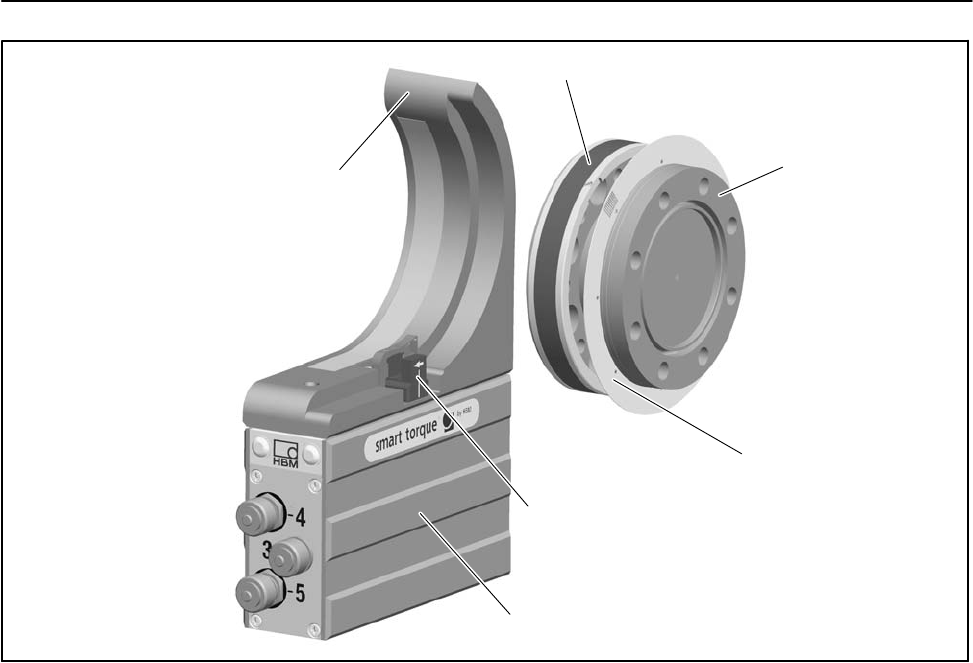
Transmitter head
Rotor
Housing
Rotational speed sensor (option)
Side A
Side B
Stator
Slotted disc (option)
Fig. 5.1: Mechanical structure, exploded view

T12
16
A1979−10.0 enHBM
7 Mechanical installation
7.1 Important precautions during installation
NOTE
A torque flange is a precision measuring element and therefore needs careful
handling. Dropping or knocking the transducer may cause permanent
damage. Make sure that the transducer cannot be overloaded, including while
it is being mounted.
Handle the transducer with care.
Check the effect of bending moments, critical rotational speeds and natural
torsional vibrations, to prevent the transducer being overloaded by
resonance sharpness.
Make sure that the transducer cannot be overloaded.
WARNING
There is a danger of the transducer breaking if it is overloaded. This can
cause danger for the operating personnel of the system in which the
transducer is installed.
Implement appropriate safety measures to avoid overloads and to protect
against resulting dangers.
Use a threadlocker (medium strength, e.g. LOCTITE) to glue the screws
into the counter thread to exclude prestressing loss due to screw
slackening, in the event of alternating loads.
Comply with the mounting dimensions to enable correct operation.
An appropriate shaft flange enables the T12 torque flange to be mounted
directly. It is also possible to mount a joint shaft or relevant compensating
element directly on the rotor (using an intermediate flange when required).
Under no circumstances should the permissible limits specified for bending
moments, lateral and longitudinal forces be exceeded. Due to the T12 torque
flange’s high torsional stiffness, dynamic shaft train changes are kept to a
minimum.

17
T12
A1979−10.0 en HBM
Important
Even if the unit is installed correctly, the zero point adjustment made at the
factory can shift by up to approx. 3% of the sensitivity. If this value is
exceeded, we advise you to check the mounting conditions. If the residual
zero offset when the unit is removed is greater than 1% of the sensitivity,
please send the transducer back to the Darmstadt factory for testing.
7.2 Conditions on site
The T12 torque transducer is protected to IP54 according to EN 60529.
Protect the transducer from coarse dirt, dust, oil, solvents and moisture.
During operation, the prevailing safety regulations for the security of
personnel must be observed (see “Safety instructions”).
There is wide ranging compensation for the effects of temperature on the
output and zero signals of the T12 torque transducer (see specifications on
page 56). This compensation is carried out at static temperatures. This
guarantees that the circumstances can be reproduced and the properties of
the transducer can be reconstructed at any time.
If there are no static temperature ratios, for example, because of the
temperature differences between flange A and flange B, the values given in
the specifications can be exceeded. Then for accurate measurements, you
must ensure static temperature ratios by cooling or heating, depending on the
application. As an alternative, check thermal decoupling, by means of heat
radiating elements such as multiple disc couplings.
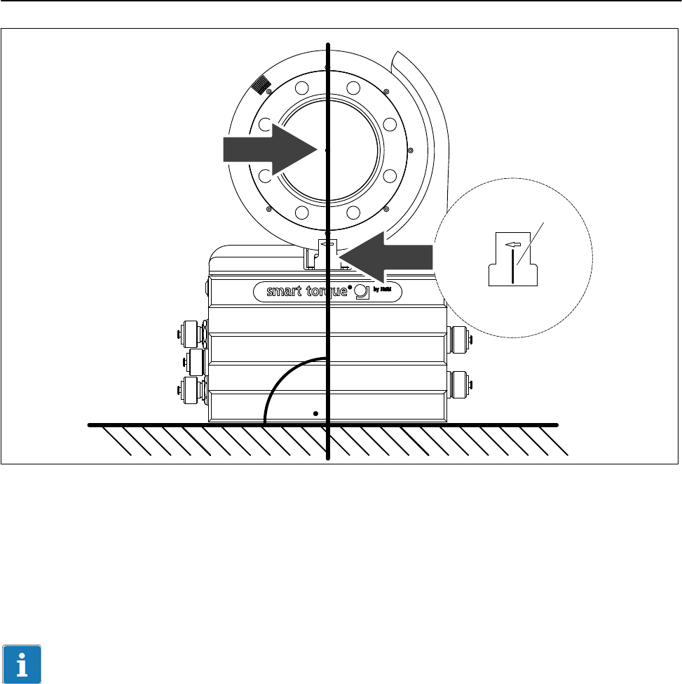
7.3 Mounting position
The transducer can be mounted in any position. With clockwise torque, the
output frequency is 10 to 15 kHz (Option 4, code DF1/DU2: 60 kHz to
90 kHz). In conjunction with HBM amplifiers or when using the voltage output,
a positive output signal (0 V to +10 V) is present.
With counterclockwise torque, the output frequency is 5 kHz to 10 kHz (Option
4, code DF1/DU2: 30 kHz to 60 kHz).
In the case of the rotational speed measuring system, an arrow is attached to
the head of the sensor to clearly define the direction of rotation. When the
transducer rotates in the direction of the arrow, a positive rotational speed
signal is output.
T12
18
A1979−10.0 enHBM
7.4 Installing the slotted disc (rotational speed measuring
system only)
To prevent damage to the rotational speed measuring system’s slotted disc
during transportation, it is not mounted on the rotor. The customer must attach
it to the mounting ring before installing the rotor in the shaft train. The
mounting ring and the associated rotational speed sensor are already
mounted at the factory.
The requisite screws, a suitable screwdriver and the threadlocker are included
among the components supplied.
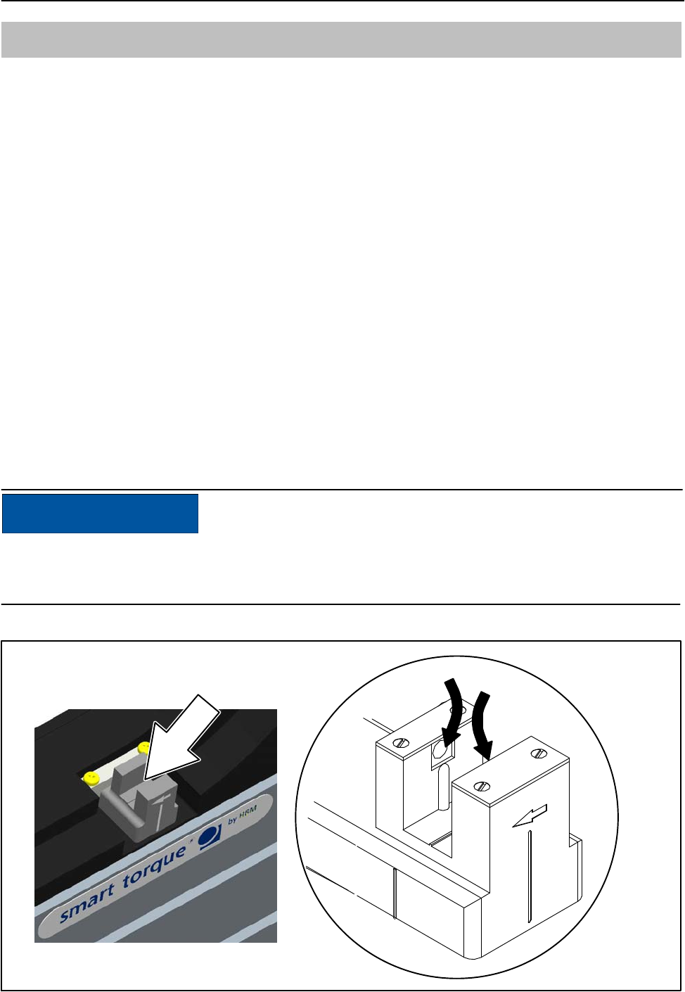
Slotted disc
Fastening screw Mounting ring
Fig. 6.1: Installing the slotted disc
Important
When carrying out the installation, be careful not to damage the slotted disc!
Installation sequence
1. Push the slotted disc onto the mounting ring and align the screw holes.
2. Apply some of the threadlocker to the screw thread and tighten the screws
(tightening torque < 0.15 Nm).
19
T12
A1979−10.0 en HBM
7.5 Installing the rotor
Tip
Usually the rotor type plate is no longer visible after installation. This is why
we include with the rotor additional stickers with the important characteristics,
which you can attach to the stator or any other relevant test-bench
components. You can then refer to them whenever there is anything you wish
to know, such as the shunt signal. To explicitly assign the data, the
identification number and the size are engraved on the rotor flange, where
they can be seen from outside.
NOTE
Make sure during installation that you do not damage the measuring zone
marked in Fig. 6.2 by using it to support tools, or knocking tools against it
when tightening screws, for example. This can damage the transducer and
produce measurement errors, or even destroy the transducer.
Fastening screw
Flange B Identification number and measuring range
Measuring zone
Fig. 6.2: Screw connections, flange B
T12
20
A1979−10.0 enHBM
1. Prior to installation, clean the plane faces of the transducer flange and the
counter flange.
For safe torque transfer, the faces must be clean and free from grease.
Use a piece of cloth or paper soaked in solvent. When cleaning, make sure
that you do not damage the transmitter coils.
2. For the flange B screw connection, use hexagon socket screws DIN EN
ISO 4762 of property class 10.9 (measuring ranges 3 kN@m to 10 kN@m:
12.9) of the appropriate length (depending on the connection geometry, see
Table 6.1).
We recommend fillister-head screws DIN EN ISO 4762, blackened,
smooth-headed, permitted size and shape variance as per DIN ISO 4759,
Part 1, product class A.
3. First tighten all the screws crosswise with 80% of the prescribed tightening
torque (Table 6.1), then tighten again crosswise, with the full tightening
torque.
4. There are relevant tapped holes on flange A for continuing the shaft train
mounting. Again use screws of property class 10.9 (measuring ranges
3kNm to 10 kNVm: 12.9), and tighten them with the prescribed moment as
specified in Table 6.1.
Fastening screw Z
Flange A
Fastening screw Z
Fig. 6.3: Screw connections, flange A

21
T12
A1979−10.0 en HBM
Important
Use a threadlocker (medium strength, e.g. LOCTITE) to glue the screws into
the counter thread to exclude prestressing loss due to screw slackening, in
the event of alternating loads.
NOTE
Comply with the maximum thread reach as per Table 6.1. Otherwise
significant measurement errors may result from torque shunt, or the
transducer may be damaged.
Measuring range Fastening screws Prescribed tightening
moment
NVm Z1) Property class NVm
100 / 200 M8
10.9
34
500 M10 67
1 k M10 67
2 k M12 115
3 k M12
12.9
135
5 k M14 220
10 k M16 340
Table 6.1: Fastening screws
1) DIN EN ISO 4762; black/oiled/mtot = 0.125
Important
Dry screw connections can result in different friction factors (see VDI 2230, for
example). This means a change to the required tightening moments.
The required tightening moments can also change if you use screws with a
surface or property class other than that specified in Table 6.1, as this affects
the friction factor.
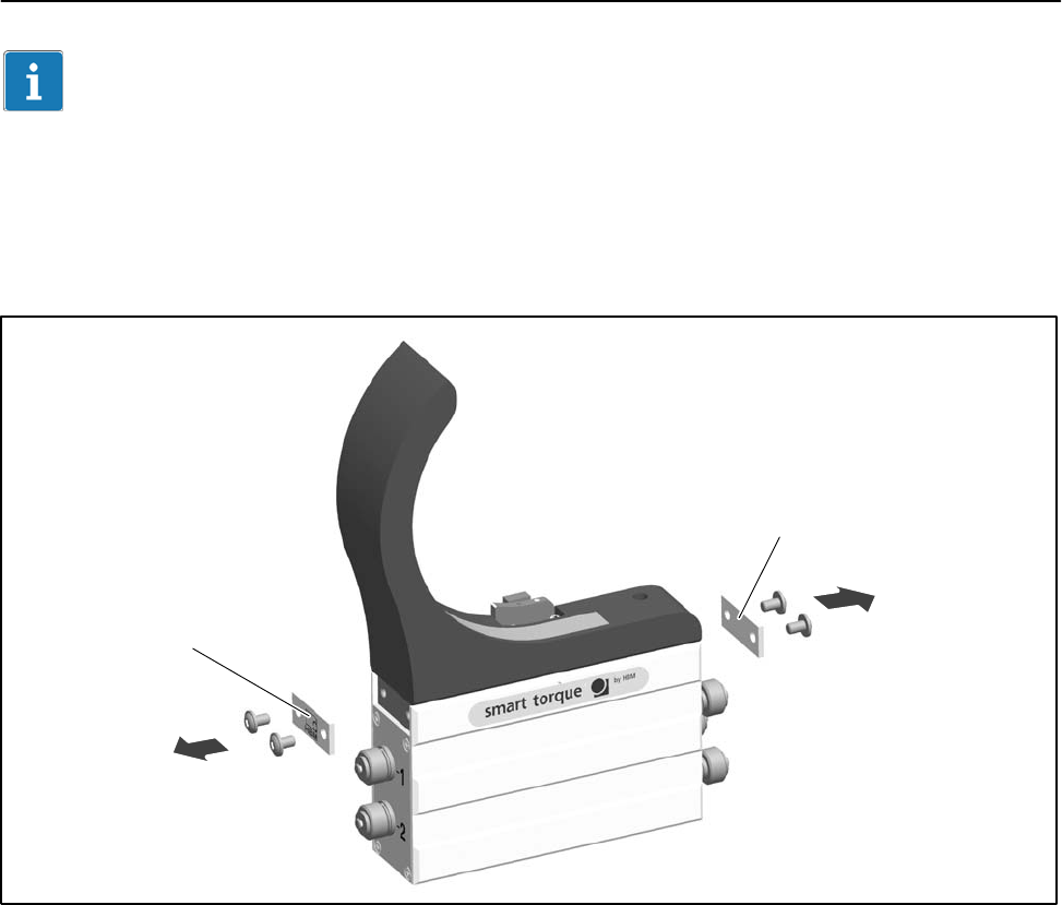
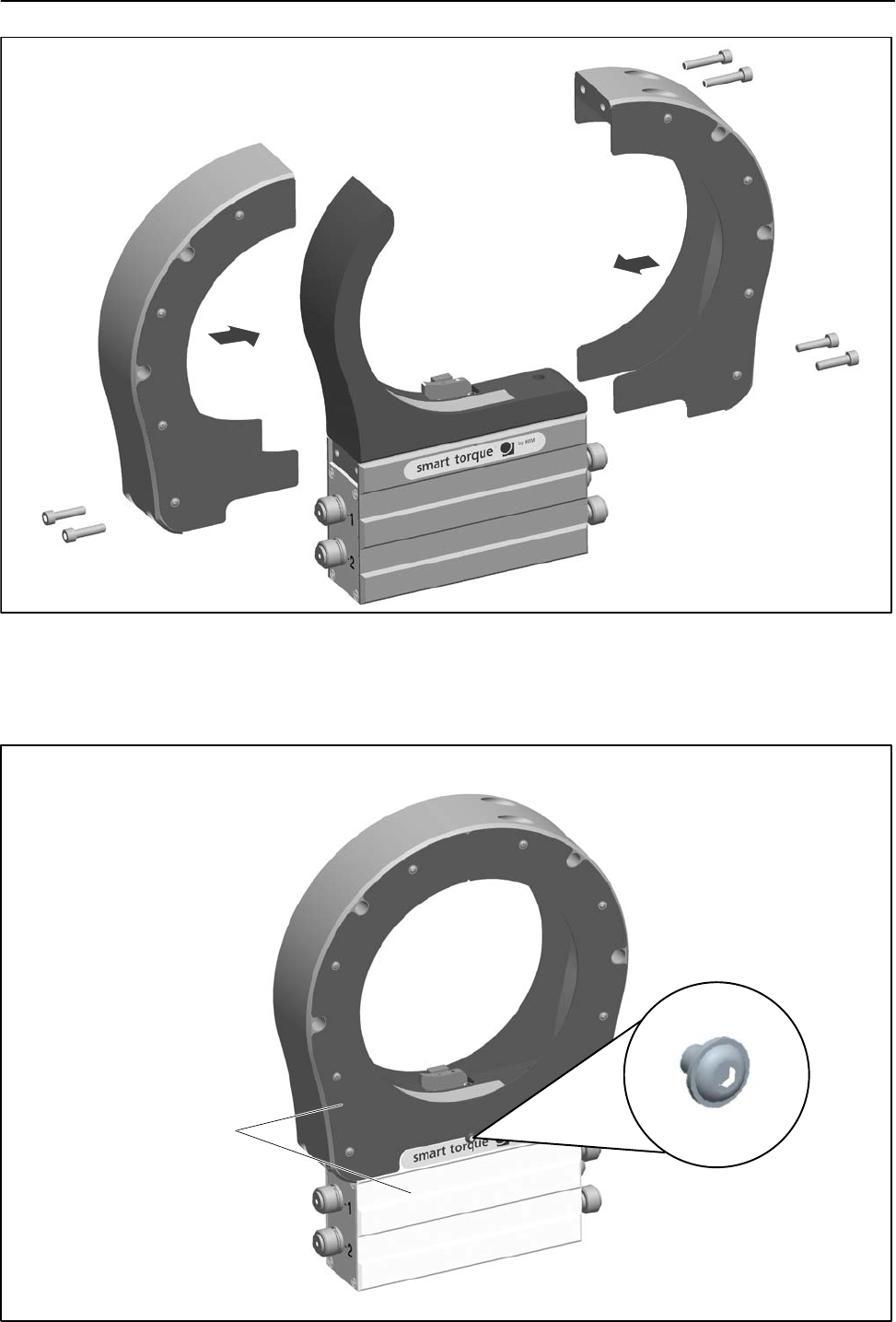
7.6 Fitting the protection against contact (option)
The protection against contact comprises two side parts and four cover plates.
It is screwed onto the stator housing.
T12
22
A1979−10.0 enHBM
Important
Use a threadlocker (medium strength, e.g. LOCTITE) to glue the connecting
screws into the counter thread.
1. Remove the side cover plates on the stator housing (see Fig. 6.4.)
Cover plate
Cover plate
Fig. 6.4: Cover plates on the stator housing
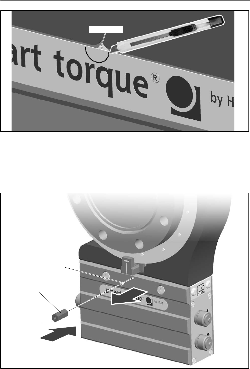
2. Only for measuring ranges 500 N@m to 3 kN@m and subsequently
ordered protection against contact: some of the tapped holes for the
locking screws are covered by attached film. Make a semicircular cutout in
the film here, with a minimum radius of 6 mm (use a cutter, as shown in
Fig. 6.5, for example).
Now remove the threaded pins from the tapped holes on both sides of the
stator.
23
T12
A1979−10.0 en HBM
Threaded pin
Fig. 6.5: Cut out the film
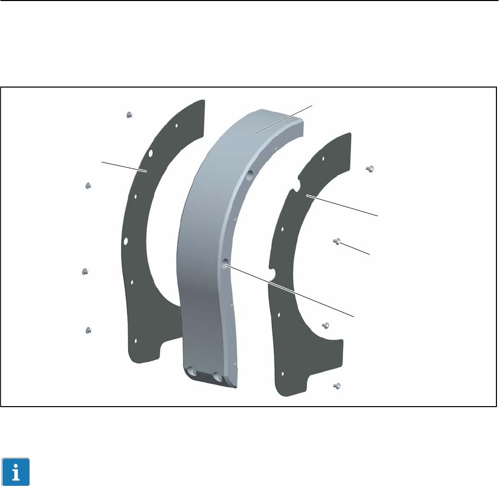
3. For 5 kN@m and 10 kN@m measuring ranges only: remove the threaded
pins from the tapped holes on both sides of the stator. Screw the spacing
bolt into the tapped hole on the side of the rotational speed sensor (see
Fig. 6.6).
Spacing bolt
Threaded pin
1
2
Fig. 6.6: Fit the spacing bolt (for 5 kN@m and 10 kN@m only)
T12
24
A1979−10.0 enHBM
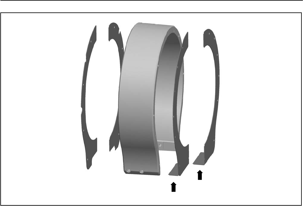
4. Screw the cover plate onto the side parts (screws with hexagon socket 2
a.f.; tightening torque MA = 1 N@m). Note that the cover plate with cutouts
must be fitted onto the side with countersunk holes! (see Fig. 6.7).
Cover plate with cutouts
Side part
2 a.f.
Countersunk hole
Cover plate with holes
Fig. 6.7: Fit the cover plates
Important
With the 5 kN@m and 10 kN@m measuring ranges, the cover plates of the
rotational speed sensor side must be angled at the bottom and fitted as
shown in Fig. 6.8.
25
T12
A1979−10.0 en HBM
Fig. 6.8: Angled cover plates (5 kN@m and 10 kN@m measuring ranges)
5. Attach each of the side parts to the stator housing with two M6x25 hexagon
socket screws (5 a.f.). Hand-tighten the screws.
6. Screw the side parts together at the top, by hand (two M6x30 hexagon
socket screws; 5 a.f.).
T12
26
A1979−10.0 enHBM
M6 x 30
M6 x 25
M6 x 25
Fig. 6.9: Fit the protection against contact halves
7. Align the protection against contact in such a way that its end face is
parallel to the stator housing.
Parallel surfaces
Locking screw (on
both sides)
Fig. 6.10: Check for parallelism
27
T12
A1979−10.0 en HBM
8. Now tighten all the screws with a tightening torque MA of 14 N@m.
9. Screw in the cover plate locking screws and tighten them at 2 N@m.
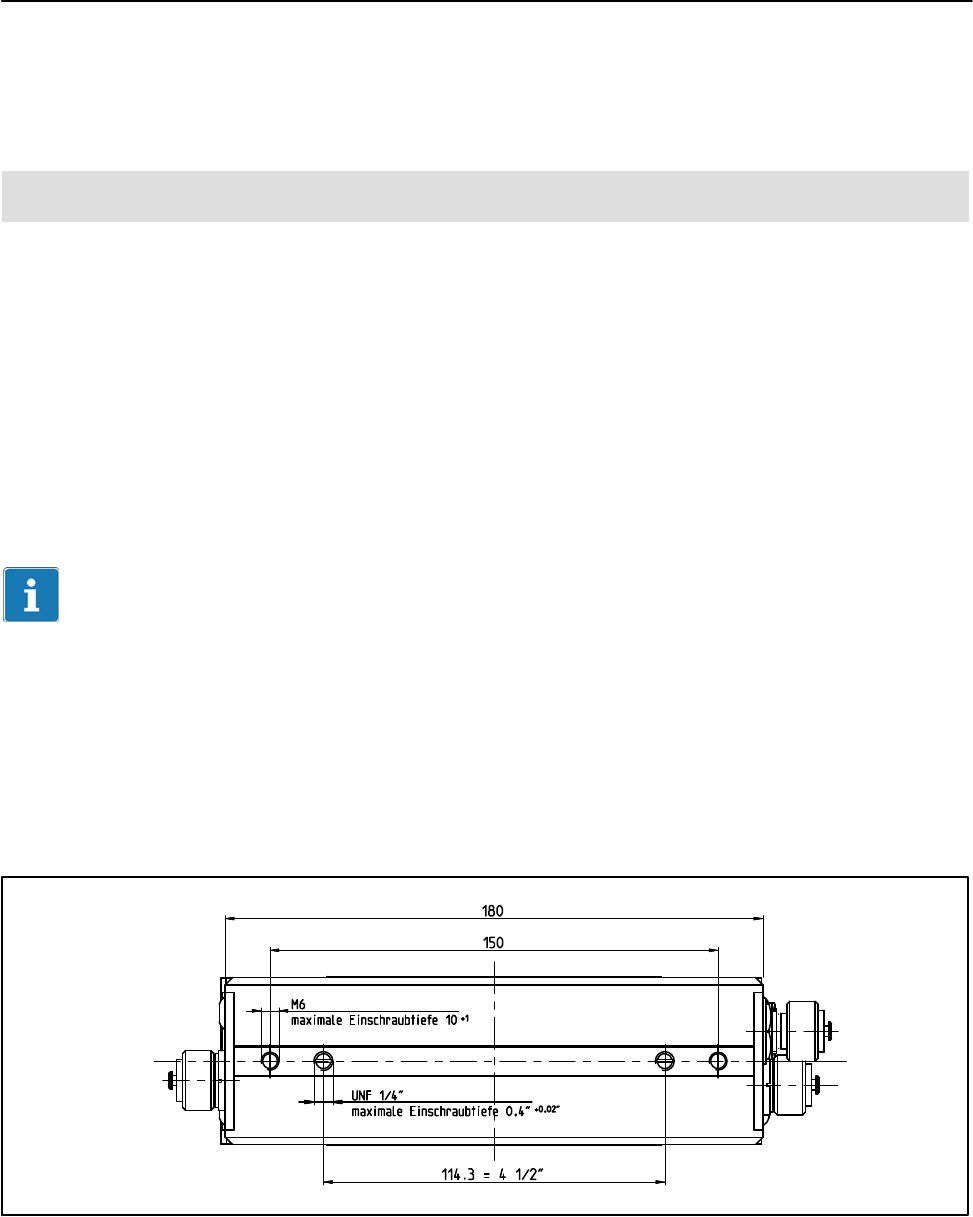
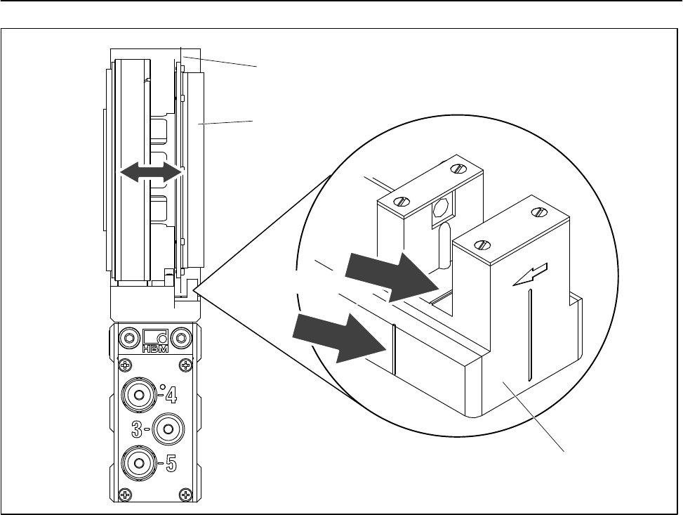
7.7 Installing the stator
On delivery, the stator has already been installed and is ready for operation.
There are four tapped holes on the base of the stator housing for mounting
the stator. Externally, two with a metric M6 thread, internally, two with a UNF
1/4” thread (closed with a plastic threaded pin).
We recommend using two metric thread DIN EN ISO 4762 fillister-head
screws with hexagon sockets of property class 10.9 of the appropriate length
(depending on the connection geometry – not included among the
components supplied; tightening torque = 14 N@m).
Tip
To allow the stator to be aligned to the rotor, make sure that repositioning is
possible (e.g. oblong holes).
The stator can be mounted radially in any position (an “upside down”
installation is possible, for example). You can also install the stator over the
protection against contact (option), see Chapter 7.7.3 .
Fig. 6.11: Mounting holes in the stator housing (viewed from below)
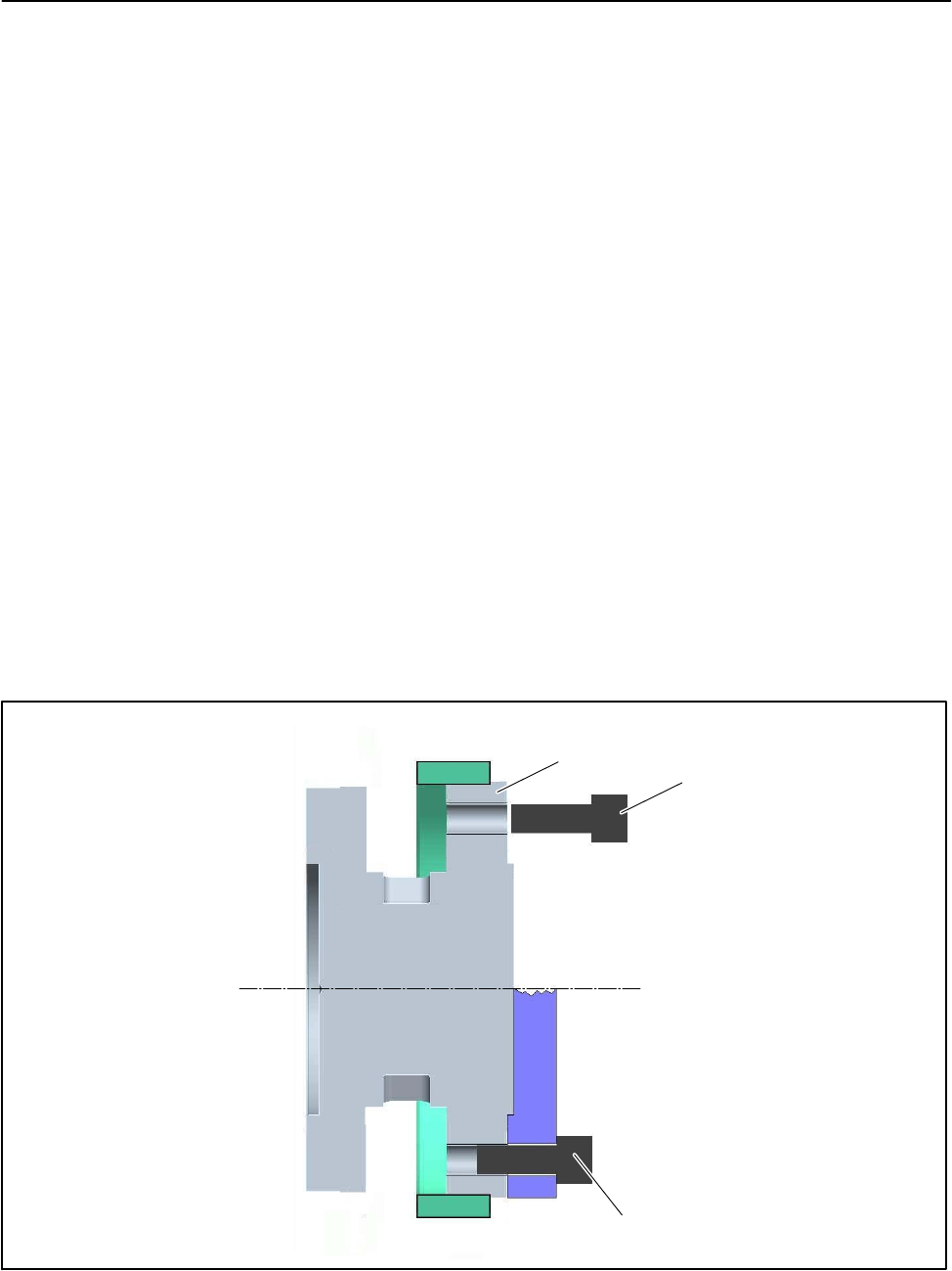
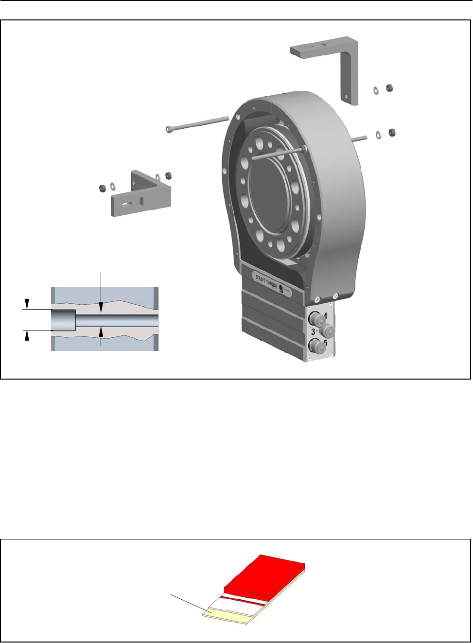
With the T12/5 kN@m and T12/10 kN@m torque transducers, we recommend
additionally supporting the stator at the protection against contact. Fig. 6.12
shows an example of how to attach an angle bracket with a bolt (A) or with a
threaded rod (B). Note that in this case, the cover plates cannot be fitted.
T12
28
A1979−10.0 enHBM
A
B
11
6.6
Section through the countersunk hole in the protection against contact
Fig. 6.12: Supporting the stator with an angle bracket (5 kN@m and 10 kN@m)
7.7.1 Preparing with the mounting kit (included among the items
supplied)
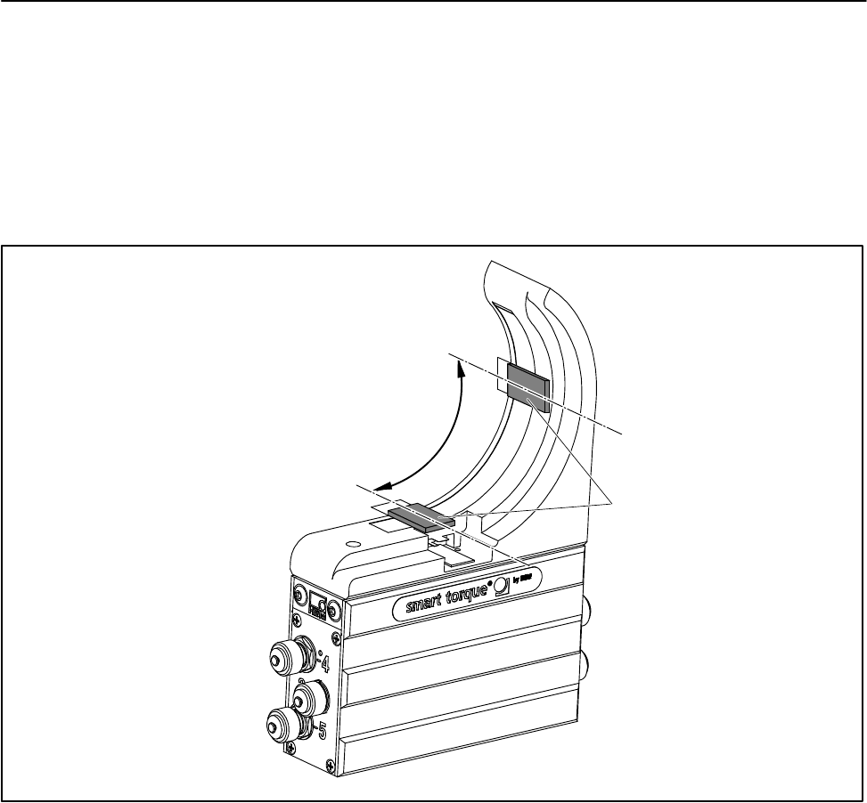
The supplied mounting kit contains self-adhesive spacers, to make it easier
for you to align the stator to the rotor.
Use the spacers to align the rotor and the stator radially and axially.
Remove the
protective film
Fig. 6.13: Mounting kit spacer
29
T12
A1979−10.0 en HBM
Radial alignment with spacers
The spacers should preferably be attached to the transmitter head, offset by
90, as shown in Fig. 6.14. If your stator is equipped with a rotational speed
measuring system, you must either shorten the spacers to an appropriate
length or attach them slightly offset, next to the rotational speed measuring
system.
90
Spacers
Fig. 6.14: Radial position of the spacers
Axial alignment with spacers
The red line on the spacers is used for axial alignment. Align the spacer in
such a way that the outer edge of the transmitter head is in line with the red
line (see Fig. 6.15).
T12
30
A1979−10.0 enHBM
Outer edge of
transmitter head
Red line
Fig. 6.15: Axial position of the spacers
Now remove the protective film and attach the spacers to the transmitter
head, as described.
Important
Remove the spacers after installation.
7.7.2 Aligning the stator
1. Position the stator on an appropriate mounting base in the shaft train, so
that there are sufficient opportunities for horizontal and vertical adjustments
to be made.
2. Should there be any misalignment in height, compensate for this by
inserting adjusting washers.
3. Only tighten the fastening screws by hand, initially.
4. Use the spacers to radially align the stator to the rotor.
5. Use the spacers to axially align the stator to the rotor. The rotor should be
in line with the edge of the red spacer, see Fig. 6.16.
31
T12
A1979−10.0 en HBM
Spacer
Transmitter rotor
Alignment line
Fig. 6.16: Axial alignment to the rotor
6. Connect the power line (plug 1 or plug 3). Notice the LED to the right of
plug 4. The stator is correctly aligned, when the LED successively
flashes red for about 10 seconds
flashes yellow for about 10 seconds
then stays permanently green (CAN Bus) or yellow or green
(PROFIBUS).
When data are being exchanged via the CAN Bus or the PROFIBUS, the LED
flashes green.
You can also use the T12 Assistant to check for the correct alignment. The
LED must stay green in the “Rotor clearance setting mode”.
7. Now fully tighten the fastening screws (tightening torque 14 N@m).
8. Remove the spacers, by first removing the adhesive strip and then the red
plastic strip.
9. Make sure that the air gap between the rotor and stator is free from
electrically conductive and other foreign matter.
T12
32
A1979−10.0 enHBM
7.7.3 Stator installation over the protection against contact (option)
You can also axially flange the stator over the protection against contact
(material: aluminum). Holes are provided in the side parts of the protection
against contact for this purpose. For this mounting, we recommend M6
fillister-head screws with hexagon sockets in accordance with
DIN EN ISO 4762; black/oiled/mtot=0.125, of the appropriate length.
Fig. 6.17: Mounting holes in the protection against contact
Customer adaptation
11
6.6
b2
b8
Measuring range Dimensions in mm (1 mm = 0.03937 inches)
b2b8
100 Nm to kNVm 56 43
5kNm 78 65
10 kNm 86 73
Table 6.2: Mounting hole dimensions
33
T12
A1979−10.0 en HBM
Fig. 6.18: Face-mounting on the engine shielding
7.8 Optical rotational speed/angle of rotation measuring
system (option)
As the stator with the optical rotational speed sensor only partially encloses
the slotted disc, if there is sufficient space available for installation, you can
subsequently move the stator tangentially over the ready-mounted rotor.
For perfect measuring mode, the slotted disc of the rotational speed
measuring system must rotate at a defined position in the sensor pickup.
7.8.1 Axial alignment
There is a mark (orientation line) in the sensor pickup for axial alignment.
When installed, the slotted disc should be exactly above this orientation line.
Divergence of up to "2 mm is permissible in measuring mode (total static
and dynamic displacement).
T12
34
A1979−10.0 enHBM
Alignment lines
Slotted disc
Sensor pickup
Flange B
Fig. 6.19: Position of the slotted disc in the rotational speed sensor
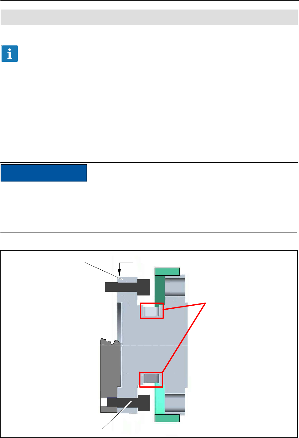
7.8.2 Radial alignment
The rotor axis and the optical axis of the rotational speed sensor must be
along a line at right angles to the stator platform. A conical machined angle (or
a colored mark) in the center of flange B and a vertical marker line on the
sensor pickup serve as aids to orientation.
35
T12
A1979−10.0 en HBM
Centering point for
aligning the rotor
Marking
Fig. 6.20: Alignment marks on rotor and stator
Connect the power line (plug 1).
Switch the LED display mode of the T12 Assistant to “optical rotational speed
system” setting mode and turn the rotor. Notice the LED to the right of plug 4;
this must stay green if the setting is correct (also see Chapter 8.3).
Important
Angle of rotation measurement is not suitable for static and quasi-static
applications!

T12
36
A1979−10.0 enHBM
8 LED status display
The LED in the stator housing (next to device plug 4) has three display
modes: standard (measuring mode), rotor clearance setting mode and setting
mode for the optical rotational speed system.
8.1 Measuring mode operation
LED color Significance
Flashing green (fast) SDO transfer taking place
Flashing green CAN device has operational status
Green For PROFIBUS option only: Data exchange taking place1)
Flashing yellow (slow) Rotor communication taking place
Yellow For PROFIBUS option only: Searching for the baud rate, or
parameterization or configuration taking place, or no data exchange
taking place1)
Flashing red Overflow for measured value (amplifier input, measured value ovfl.),
frequency or analog output
Red Error situation
1) When PROFIBUS option exists: Messages to the PROFIBUS take precedence over messages to the CAN Bus.
8.2 Rotor clearance setting mode operation
LED color Significance
Green Rotor-stator alignment is OK
Yellow Rotor-stator alignment is borderline
Red Rotor-stator alignment is not OK
8.3 Rotational speed measuring system setting mode
operation
LED color Significance
Green The position of the two sensors is OK, the signals (F1/F2) are 90 or
270 phase-shifted and can be correctly evaluated
Yellow The phase relation of the two sensor signals is not optimum, there is a
variation of 10 to 30
Red The phase relation of the two sensor signals is not correct, there is a
variation of more than 30
For more information on setting mode, look in the T12 Assistant online Help.

37
T12
A1979−10.0 en HBM
9 Electrical connection
9.1 General information
Detailed instructions for connecting the T12 to the CAN Bus or the
PROFIBUS can be found in the “T12 CAN Bus/PROFIBUS” interface
description (in pdf format) on the T12 system CD.
To make the electrical connection between the torque transducer and the
measuring amplifier, we recommend using shielded, low-capacitance
measurement cables from HBM.
With extension cables, make sure that there is a proper connection with
minimum contact resistance and good insulation. All plug connections or
swivel nuts nuts must be fully tightened.
Do not route the measurement cables parallel to power lines and control
circuits. If this cannot be avoided (in cable pits, for example), maintain a
minimum distance of 50 cm and also draw the measurement cable into a steel
tube.
Avoid transformers, motors, contactors, thyristor controls and similar
stray-field sources.
Consider longer cable of approximately 40cm due to the installation of the
wounded core (toroidal core).
Important
Transducer connection cables from HBM with plugs attached are identified in
accordance with their intended purpose (Md or n). When cables are
shortened, inserted into cable ducts or installed in control cabinets, this
identification can get lost or become concealed. If this is the case, it is
essential for the cables to be re-labeled!
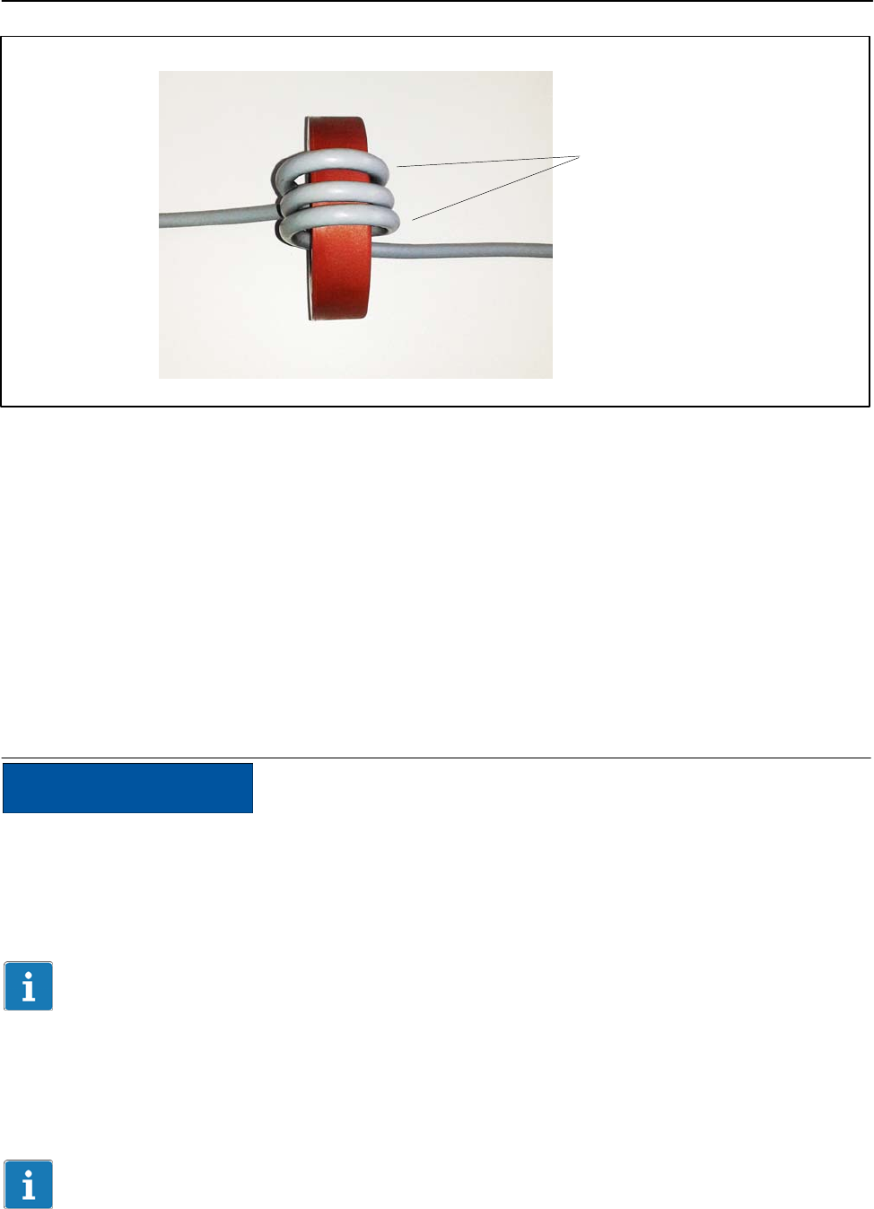
Tape wound core (toroidal core):
To suppress high frequencies a tape wound core (toroidal core) on the power
cable has to be used. Use at least 3 loops of the cable.
T12
38
A1979−10.0 enHBM
3 loops
Fig. 6.21: Installation Example
If the core has to be removed for any purpose (e.g. for maintenance), it must
be replaced on the cable. Use only wounded core (toroidal core) of the correct
type.
Type: Vitroperm R
Model No.: T60006−22063W517
Size: external diameter x internal diameter x height = 63 x 50 x 25
The core should be placed as close as possible to the connector. However,
prevent stress on the connector due to the extra weight of the cable.
NOTE
For US stator Version Option 9, Code U the use of a tape wound core (tor-
oidal core) on the power cable (plug 1 or plug3) is mandatory to ensure com-
pliance with FCC regulations.
Important
For US Version Option 9, Code U the use of a tape wound core (toroidal core)
on the signal cable is mandatory to ensure compliance with FCC regulations.
The cables and plugs for connectors 1, 2 and 3 are compatible with the
T10FS torque flange.
39
T12
A1979−10.0 en HBM
9.2 Shielding design
The cable shield is connected in accordance with the Greenline concept. This
encloses the measurement system (without the rotor) in a Faraday cage. It is
important that the shield is laid flat on the housing ground at both ends of the
cable. Any electromagnetic interference active here does not affect the
measurement signal. Special electronic coding methods are used to protect
the purely digital signal transmission between the transmitter head and the
rotor from electromagnetic interference.
In the case of interference due to potential differences (compensating
currents), supply voltage zero and housing ground must be disconnected on
the amplifier and a potential equalization line established between the stator
housing and the amplifier housing (copper conductor, 10 mm2 wire
crosssection).
Should differences in potential between the machine rotor and stator cause
interference, because of unchecked leakage, for example, this can usually be
overcome by connecting the rotor definitively to ground, by a wire loop, for
example. The stator should be fully grounded in the same way.
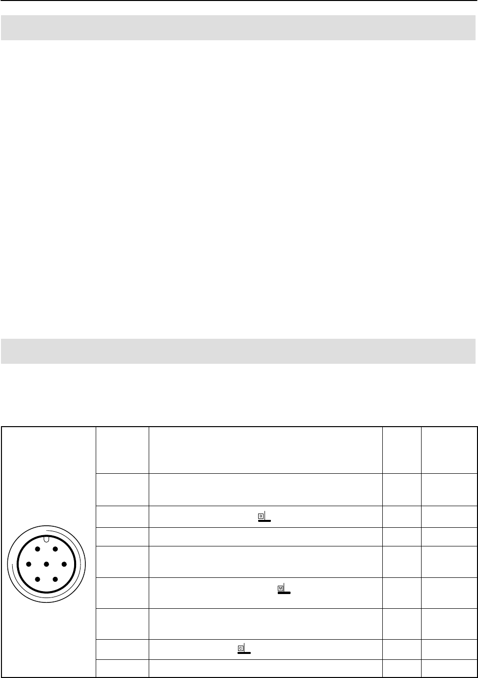
9.3 Connector pin assignment
Assignment for plug 1:
Supply voltage and frequency output signal.
61
572
43
Binder 423
device plug
Top view
Plug
pin
Assignment Color
code
D-Sub-
plug
pin
1Torque measurement signal (frequency output;
5 V1)/0) wh 13
2 Supply voltage 0 V; bk 5
3Supply voltage 18 V 30 V bu 6
4Torque measurement signal (frequency output;
5 V1)V) rd 12
5Measurement signal 0 V;
symmetrical
gy 8
6Shunt signal trigger 5 V 30 V and TEDS for
torque
gn 14
7Shunt signal 0 V; gy 8
Shielding connected to housing ground
1) RS−422 complementary signals; with cable lengths exceeding 10 m, we recommend
using a termination resistor R=120 ohms between the wires (wh) and (rd).
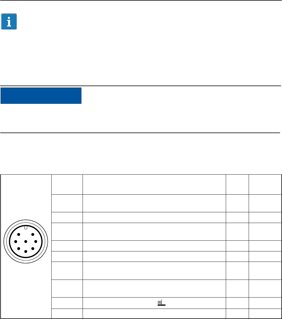
T12
40
A1979−10.0 enHBM
Important
If plug 1 is used to power the device a tape wound core (toroidal core) is nec-
cessary to suppresse high frequencies in order to ensure compliance with
FCC regulations
NOTE
Torque transducers are only intended for operation with a DC supply voltage
(separated extra-low voltage), see page 43.
Assignment for plug 2:
Rotational speed measuring system
Binder 423
device plug
Top view
7
3
4
6
2
5
18
Plug
pin
Assignment Color
code
Sub-D
plug pin
1Rotational speed measurement signal
(pulse string, 5 V1); 0)
rd 12
2Not in use bu 2
3Rotational speed measurement signal
(pulse string, 5 V1); phase-shifted 90) gy 15
4Not in use bk 3
5TEDS for rotational speed vt 9
6Rotational speed measurement signal (pulse
string, 5 V1); 0)
wh 13
7Rotational speed measurement signal
(pulse string, 5 V1); phase-shifted 90)gn 14
8Measurement signal 0 V bk2) 8
Shielding connected to housing ground
1) RS−422 complementary signals; with cable lengths exceeding 10 m, we recommend
using R=120 ohms termination resistors between wires (rd) and (wh), as well as (gy)
and (gn).
2) Color code brown (br) for Kab 163 and Kab 164.
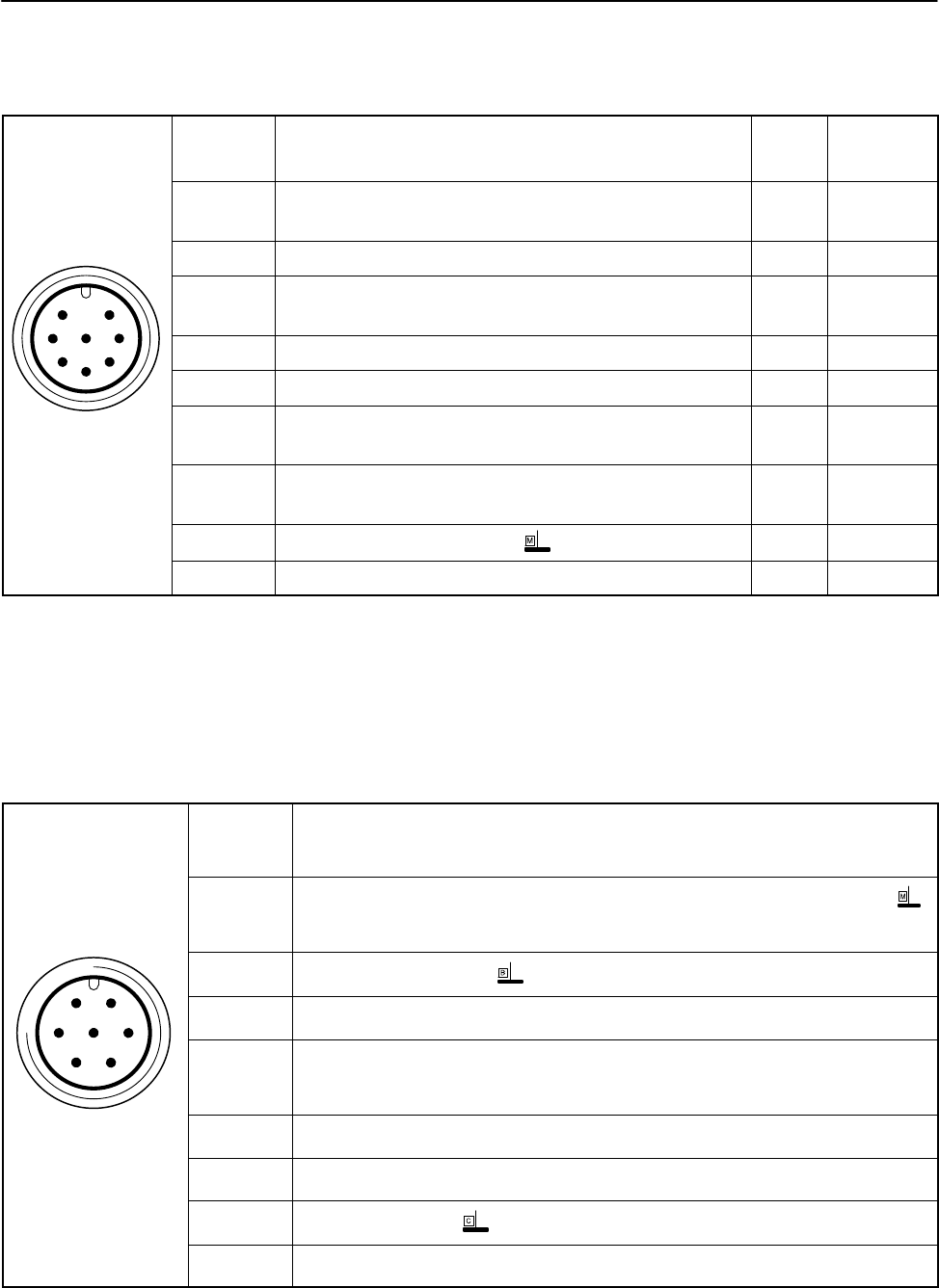
41
T12
A1979−10.0 en HBM
Assignment for plug 2:
Rotational speed measuring system with reference signal
Binder 423
device plug
Top view
7
3
4
6
2
5
18
Plug
pin
Assignment Color
code
Sub-D
plug pin
1Rotational speed measurement signal (pulse
string, 5 V1); 0)
rd 12
2Reference signal (1 pulse/rev., 5 V1))bu 2
3Rotational speed measurement signal
(pulse string, 5 V); phase-shifted 90) gy 15
4Reference signal (1 pulse/rev., 5 V1)) bk 3
5TEDS for rotational speed vt 9
6Rotational speed measurement signal (pulse
string, 5 V1); 0)
wh 13
7Rotational speed measurement signal
(pulse string, 5 V); phase-shifted 90)gn 14
8Measurement signal 0 V bk2) 8
Shielding connected to housing ground
1) RS−422 complementary signals; with cable lengths exceeding 10 m, we recommend
using R=120 ohms termination resistors between wires (rd) and (wh), (bu and (bk), (gy)
and (gn).
2) Color code brown (br) for Kab 163 and Kab 164.
Assignment for plug 3:
Supply voltage and voltage output signal.
61
572
43
Binder 423
device plug
Top view
Plug
pin
Assignment
1Torque/rotational speed measurement signal (voltage output; 0 V )
or rotational speed measurement signal (0 V)
2Supply voltage 0 V;
3Supply voltage 18 V to 30 V DC
4Torque measurement signal (voltage output; "10 V)
or rotational speed measurement signal ("10 V)
5Not in use
6Shunt signal trigger 5 V to 30 V and TEDS for torque
7Shunt signal 0 V;
Shielding connected to housing ground

T12
42
A1979−10.0 enHBM
Important
If plug 3 is used to power the device a tape wound core (toroidal core) is nec-
cessary to suppresse high frequencies in order to ensure compliance with
FCC regulations.
NOTE
Do not use cable KAB149 to connect the voltage output signal at AP01i to
ML01B of the MGCplus system!
This cable is only suitable for connecting the frequency output signal.
The analog output is designed as a monitoring output. The power
transmission of the torque transducer can cause interference on the
connected cable of up to 40 mV at 13.56 MHz. This interference can be
suppressed by connecting a 100 nF capacitor in parallel, directly at the
connected measuring instrument.
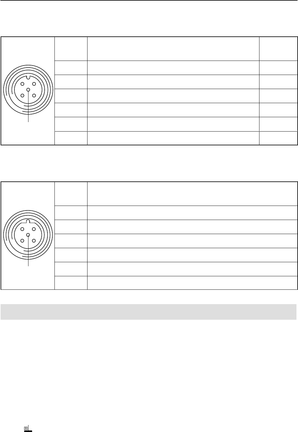
Assignment for plug 4:
Standard CAN Bus; A-coded, black washer
Top view
12
43
5
Binder 713
(M12x1)
Plug
pin
Assignment Color
code
1 Shield −
2Not in use −
3CAN ground −
4CAN HIGH-dominant high wh
5CAN LOW-dominant low bu
Shielding connected to housing ground
43
T12
A1979−10.0 en HBM
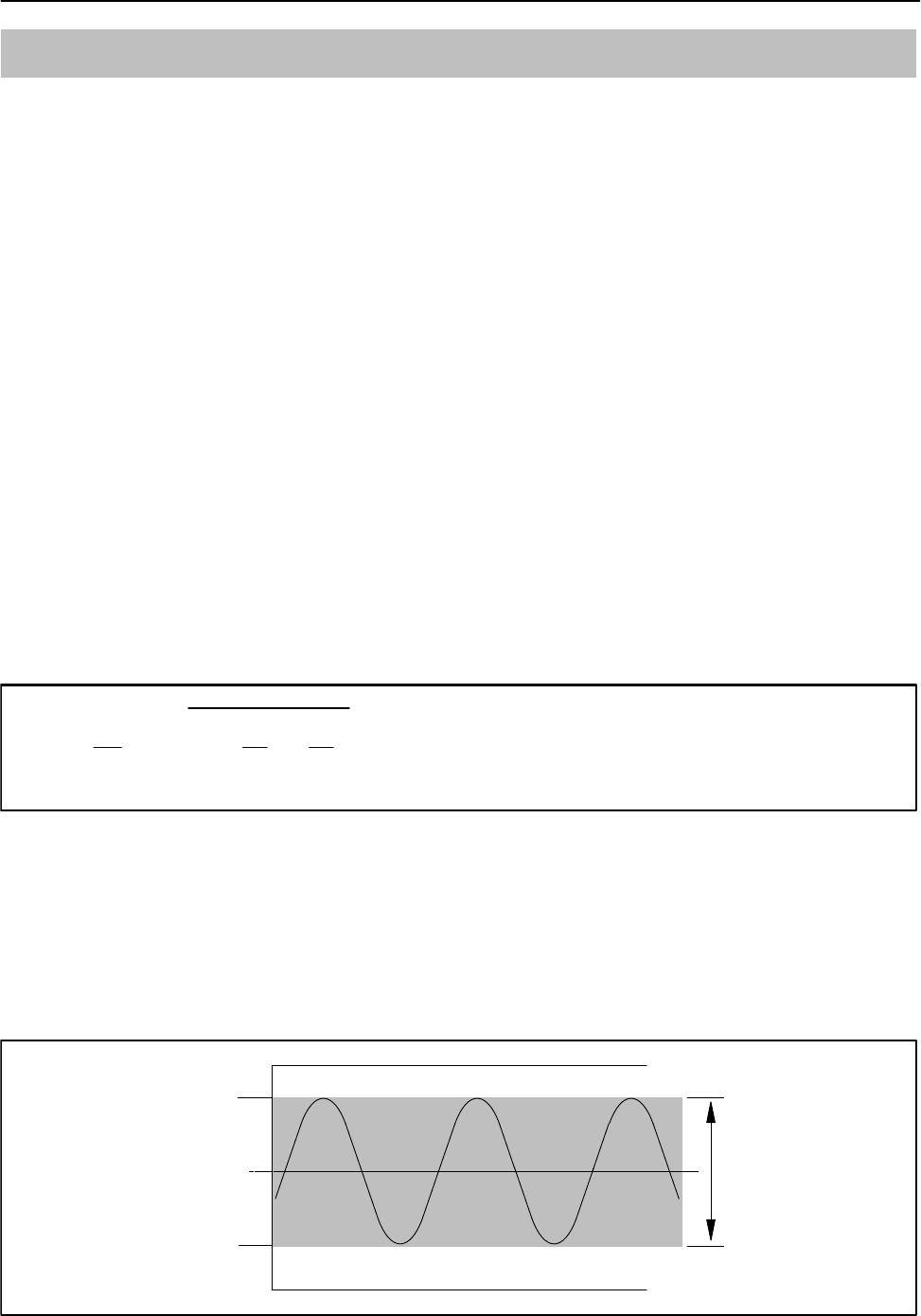
Assignment for plug 5:
CAN Bus; second device plug; A-coded, black washer
Top view
12
43
5
Binder 713
(M12x1)
Plug
pin
Assignment Color
code
1 Shield −
2Not in use −
3CAN ground −
4CAN HIGH-dominant high wh
5CAN LOW-dominant low bu
Shielding connected to housing ground
Assignment for plug 5:
PROFIBUS (option); B-coded, violet washer
Top view
12
43
5
Binder 715
(M12x1)
Plug
pin
Assignment
15 V (typ. 50 mA)
2PROFIBUS A
3PROFIBUS ground
4PROFIBUS B
5Shield
Shielding connected to housing ground
9.4 Supply voltage
The transducer must be operated with a separated extra-low voltage (nominal
(rated) supply voltage 18 to 30 VDC). You can supply one or more torque
flanges within a test bench at the same time. Should the device be operated
on a DC voltage network1), additional precautions must be taken to discharge
excess voltages.
The notes in this section relate to the self-contained operation of the T12
without HBM system solutions.
The supply voltage is electrically isolated from signal outputs and shunt signal
inputs. Connect a separated extra-low voltage of 18 V to 30 V to pin 3 (+) and
pin 2 ( ) of plug 1 or 3. We recommend that you use HBM cable
KAB 8/00−2/2/2 and the relevant Binder sockets, that at nominal (rated)

T12
44
A1979−10.0 enHBM
voltage (24 V) can be up to 50 m long and in the nominal (rated) voltage
range, 20 m long (see Accessories, page 88).
If the permissible cable length is exceeded, you can feed the supply voltage in
parallel over two connection cables (plugs 1 and 3). This enables you to
double the permissible length. Alternatively, install an on-site power supply.
If you feed the supply voltage through an unshielded cable, the cable must be
twisted (interference suppression). We also recommend that a ferrite element
should be located close to the connector plug on the cable, and that the stator
should be grounded.
Important
The instant you switch on, a current of up to 4 A may flow and this may switch
off power supplies with electronic current limiters.
1) Distribution system for electrical energy with greater physical expansion (over several test benches, for
example) that may possibly also supply consumers with high nominal (rated) currents.

45
T12
A1979−10.0 en HBM
10 Shunt signal
The T12 torque transducer supplies a shunt signal, at either 50% or 10% of
the nominal (rated) torque, as selected. Activate this function via the T12
Assistant or the shunt signal trigger on plug 1 or plug 3 (see Section 9.3). The
last shunt selected in the T12 Assistant is then triggered.
The internal signal conditioning may cause a delay in triggering of about 5
seconds.
To obtain stable conditions, we recommend activating the shunt signal only
once the transducer has been warming up for 15 minutes.
The framework conditions for reproducibility (e.g. the mounting conditions)
must be established in order to reproduce the measured values in the
manufacturing certificate.
Important
The transducer should not be under load when the shunt signal is being
measured, as the signal is applied additively.
After about 5 minutes, the shunt signal is automatically deactivated.
T12
46
A1979−10.0 enHBM
11 Load-carrying capacity
Nominal (rated) torque can be exceeded statically up to the limit torque. If the
nominal (rated) torque is exceeded, additional irregular loading is not
permissible. This includes longitudinal forces, lateral forces and bending
moments. Limit values can be found in the “Specifications” chapter (Chapter
15, page 56).
Measuring dynamic torque
The torque transducer is suitable for measuring static and dynamic torques.
The following apply to the measurement of dynamic torque:
The T12 calibration run for static measurements is also valid for dynamic
torque measurements.
The natural frequency f0 of the mechanical measuring system depends on
the moments of inertia J1 and J2 of the connected rotating masses and the
T12’s torsional stiffness.
Use the equation below to approximately determine the natural frequency f0 of
the mechanical measuring system:
f0+1
2p·c
T·ǒ1
J1)1
J2Ǔ
Ǹf0= natural frequency in Hz
J1, J2= mass moment of inertia in kgm2
cT= torsional stiffness in Nm/rad
The maximum oscillation width is 200% (measuring range 3 kN@m to 10
kN@m: 160%) of the typical nominal (rated) torque for the T12 (see
“Specifications”, page 56) The oscillation width must lie between the
maximum upper and lower torques of the defined loading range. The same
also applies to transient resonance points.
0
Upper maximum
torque 100%
Lower maximum
torque 100%
Oscillation width
200% Mnom
(3 kNm to
10 kNm: 160%)
Fig. 10.1: Permissible dynamic loading

47
T12
A1979−10.0 en HBM
12 TEDS
TEDS (Transducer Electronic Data Sheet) allows you to store the transducer
data (characteristic values) in a chip, that can be read out by a connected
measuring instrument.
There are two TEDS blocks in the T12 digital torque transducer:
TEDS 1 (torque): a choice of voltage sensor or frequency sensor/pulse
sensor
TEDS 2 (rotational speed/angle of rotation): frequency sensor/pulse sensor
The data are written automatically into the TEDS blocks by the T12 Assistant,
when the parameters are stored. The same menu is used to select whether
the device should be presented as a voltage sensor or as a frequency sensor
or as a frequency or pulse sensor. A template is also stored, which provides
the conversion factors for the different physical units.
The T12 is a transducer, that is to say, the T12 does not read the TEDS
blocks, it only writes them. (We therefore strongly advise against editing the
values with the HBM TEDS Editor, for example!)
You can read the data of the TEDS block with the TEDS Editor.
Important
To ensure that the data of the TEDS blocks correspond to the properties of
the T12 torque transducer, you must not overwrite the information from the
measuring amplifier.
For more information on TEDS, look in the T12 Assistant online Help.
Content of the TEDS memory as defined in IEEE 1451.4
The information in the TEDS memory is organized into areas, which
are prestructured to store defined groups of data in table form.
Only the entered values are stored in the TEDS memory itself. The amplifier
firmware assigns the interpretation of the respective numerical values. This
places a very low demand on the TEDS memory. The memory content is
divided into three areas:
Area 1:
An internationally unique TEDS identification number (cannot be changed).

T12
48
A1979−10.0 enHBM
Area 2:
The base area (basic TEDS), to the configuration defined in standard
IEEE1451.4. The transducer type, the manufacturer and the transducer serial
number are contained here.
Example:
TEDS content of a T12/1 kN@m transducer
TEDS
Manufacturer HBM (31)
Model T12 (15)
Version letter A
Version number 2 first position of stator ident no.
Serial number 7 first position of stator ident no.
Area 3:
Data specified by the manufacturer and the user are contained in this area.
Typical values for an HBM T12/1 kN@m torque transducer are shown in the
“Value” column of the table below.
Torque
HBM has already written the “Frequency/Pulse Sensor” and “High Level
Voltage Output Sensor” templates for the torque measurand.

49
T12
A1979−10.0 en HBM
Template: Frequency/Pulse Sensor
Parameter Value Unit Require
d user
rights
Explanation
Transducer Electrical
Signal Type
Pulse
Sensor
ID
Minimum Torque 0.000 N@m CAL The physical measurand and
unit are defined when the
template is created, after which
they cannot be changed.
Maximum Torque 1000 N@m CAL
Pulse Measurement Type Frequency
Minimum Electrical
Value
10000 Hz CAL The difference between these
values is the nominal (rated)
sensitivity.
Maximum Electrical Value 15000 Hz CAL
Mapping Method Linear
Discrete Signal Type Bipolar ID
Discrete Signal Amplitude 4 V
Discrete Signal
Configuration
Single
Transducer Response
Time
0 secon
ds
Excitation Level nom 24 V
Excitation Level min 18 V
Excitation Level max 30 V
Excitation Type DC
Excitation Current draw 0.5 A
Calibration Date 1-Nov-2006 CAL Date of the last calibration or
creation of the manufacturing
certificate (if no calibration
carried out), or of the storage of
the TEDS data (if only nominal
(rated) values from the data
sheet were used).
Format: day-month-year.
Abbreviations for the months:
Jan, Feb, Mar, Apr, May, Jun,
Jul, Aug, Sep, Oct, Nov, Dec.
Calibration Initials HBM or PTB CAL Initials of the calibrator or
calibration laboratory
concerned.
Calibration Period
(Days)
0 days CAL Time before recalibration,
calculated from the date
specified under Calibration
Date.
Measurement location ID 0 USR Identification number for the
measuring point.
Can be assigned according to
the application. Possible
values: a number from 0 to
2047.

T12
50
A1979−10.0 enHBM
Template: High Level Voltage Sensor
Parameter Value Unit Required
user
rights
Explanation
Minimum Torque 0.000 N@m CAL The physical measurand and
unit are defined when the
template is created, after which
they cannot be changed.
Maximum Torque 1000 N@m CAL
Minimum Electrical Value 0 V CAL The difference between these
values is the nominal (rated)
sensitivity.
Maximum Electrical Value 10 V CAL
Discrete Signal Type Bipolar ID
Discrete Signal Amplitude 5 V
Discrete Signal Single
Transducer Response
Time
0
Excitation Level nom 24 V
Excitation Level min 18 V
Excitation Level max 30 V
Excitation Type DC
Excitation Current draw 0.5 A
Calibration Date 1-Nov-2006 CAL Date of the last calibration or
creation of the manufacturing
certificate (if no calibration
carried out), or of the storage of
the TEDS data (if only nominal
(rated) values from the data
sheet were used).
Format: day-month-year.
Abbreviations for the months:
Jan, Feb, Mar, Apr, May, Jun,
Jul, Aug, Sep, Oct, Nov, Dec.
Calibration Initials HBM or
PTB
CAL Initials of the calibrator or
calibration laboratory
concerned.
Calibration Period (Days) 0 days CAL Time before recalibration,
calculated from the date
specified under Calibration
Date.
Measurement Location ID 0 USR Identification number for the
measuring point. Can be
assigned according to the
application. Possible values: a
number from 0 to 2047.

51
T12
A1979−10.0 en HBM
Rotational speed/angle of rotation
HBM has already written the “Frequency/Pulse Sensor” template for the
rotational speed measurand.
Template: Frequency/Pulse Sensor
Parameter Value Unit Required
user
rights
Explanation
Transducer Electrical
Signal Type
Pulse
Sensor
ID
Minimum Frequency 0.000 Hz CAL The physical measurand and
unit are defined when the
template is created, after which
they cannot be changed.
Maximum Frequency 108.000 k Hz CAL
Pulse Measurement Type Frequency
Minimum Electrical Value 0 Hz CAL
Maximum Electrical Value 108.000 k Hz CAL
Mapping Method Linear
Discrete Signal Type Bipolar ID
Discrete Signal Amplitude 4 V
Discrete Signal
Configuration
Double
phase plus
zero index
Transducer Response
Time
0 seco
nds
Excitation Level nom 24 V
Excitation Level min 18 V
Excitation Level max 30 V
Excitation Type DC
Excitation Current draw 0.5 A
Calibration Date 1-Nov-2006 CAL Date of the last calibration or
creation of the manufacturing
certificate (if no calibration
carried out), or of the storage of
the TEDS data (if only nominal
(rated) values from the data
sheet were used).
Format: day-month-year.
Abbreviations for the months:
Jan, Feb, Mar, Apr, May, Jun,
Jul, Aug, Sep, Oct, Nov, Dec.
Calibration Initials HBM or
PTB
CAL Initials of the calibrator or
calibration laboratory
concerned.
Calibration Period
(Days)
0 days CAL Time before recalibration,
calculated from the date
specified under Calibration
Date.

T12
52
A1979−10.0 enHBM
Template: Frequency/Pulse Sensor
Parameter Value Unit Required
user
rights
Explanation
Measurement location ID 0 USR Identification number for the
measuring point. Can be
assigned according to the
application. Possible values: a
number from 0 to 2047.
Transducer Electrical
Signal Type
Pulse
Sensor
ID
Minimum Frequency 0.000E+000 degr
ees
CAL The physical measurand and
unit are defined when the
template is created, after which
they cannot be changed.
Maximum Frequency 3.6E+002 degr
ees
CAL
Pulse Measurement Type Count
Minimum Electrical Value 0.0 Imp CAL The difference between these
values is the nominal (rated)
sensitivity.
Maximum Electrical Value 360 Imp CAL
Mapping Method Linear
Discrete Signal Type Bipolar ID
Discrete Signal Amplitude 4 V
Discrete Signal
Configuration
Double
phase plus
zero index
Transducer Response
Time
0 seco
nds
Excitation Level nom 24 V
Excitation Level min 18 V
Excitation Level max 30 V
Excitation Type DC
Excitation Current draw 0.5 A
Calibration Date 1-Nov-2006 CAL Date of the last calibration or
creation of the manufacturing
certificate (if no calibration
carried out), or of the storage of
the TEDS data (if only nominal
(rated) values from the data
sheet were used).
Format: day-month-year.
Abbreviations for the months:
Jan, Feb, Mar, Apr, May, Jun,
Jul, Aug, Sep, Oct, Nov, Dec.

53
T12
A1979−10.0 en HBM
Template: Frequency/Pulse Sensor
Parameter Value Unit Required
user
rights
Explanation
Calibration Initials HBM or
PTB
CAL Initials of the calibrator or
calibration laboratory
concerned.
Calibration Period
(Days)
0 days CAL Time before recalibration,
calculated from the date
specified under Calibration
Date.
Measurement location ID 0 USR Identification number for the
measuring point.
Can be assigned according to
the application. Possible
values: a number from 0 to
2047.
T12
54
A1979−10.0 enHBM
13 Maintenance
The T12 torque transducer without a rotational speed measuring system is
maintenance-free.
Cleaning the rotational speed measuring system
During operation and depending on the ambient conditions, the slotted disc of
the rotor and the associated optical system of the stator sensor can get dirty.
This becomes noticeable, for example:
in transducers with a reference pulse, when an increment error is displayed
in the “Rotational speed signal” status in the T12 Assistant.
in transducers without a reference pulse, when there are cyclic intrusions
into the rotational speed signal.
Remedy:
1. Use compressed air (up to 6 bar) to clean the slotted disc.
2. Carefully clean the optical system of the sensor with a dry cotton bud or
one soaked with pure spirit.
NOTE
Do not use any other solvent to clean the optical system of the sensor! It
could alter the optical properties (make plastic cloudy).
Fig. 12.1: Cleaning points on the rotational speed sensor

55
T12
A1979−10.0 en HBM
14 Waste disposal and environmental protection
All electrical and electronic products must be disposed of as hazardous
waste. The correct disposal of old equipment prevents ecological damage and
health hazards.
Symbol:
Meaning: Statutory waste disposal mark
The electrical and electronic devices that bear this symbol are subject to the
European waste electrical and electronic equipment directive 2002/96/EC.
The symbol indicates that, in accordance with national and local
environmental protection and material recovery and recycling regulations, old
devices that can no longer be used must be disposed of separately and not
with normal household garbage.
As waste disposal regulations may differ from country to country, we ask that
you contact your supplier to determine what type of disposal or recycling is
legally applicable in your country.
Packaging
The original packaging of HBM devices is made from recyclable material and
can be sent for recycling. Store the packaging for at least the duration of the
warranty. In the case of complaints, the torque flange must be returned in the
original packaging.
For ecological reasons, empty packaging should not be returned to us.

T12
56
A1979−10.0 enHBM
15 Specifications
15.1 Nominal (rated) torque 100 NVm to 1 kNVm
Type T12
Accuracy class 0.03
Torque measuring system
Nominal (rated) torque Mnom
Nm 100 200 500
kNm 1
Nominal (rated) rotational speed nnom
Option 3, code L 1) rpm 15 000 12 000
Option 3, code H 1) rpm 18 000 16 000
Non-linearity including hysteresis, related to
nominal (rated) sensitivity
Fieldbuses, frequency output 10 kHz/60 kHz
For a max. torque in the range:
between 0% of Mnom and 20% of Mnom
> 20% of Mnom and 60% of Mnom
> 60% of Mnom and 100% of Mnom
%
%
%
<"0.006 (optional <"0.004)
<"0.013 (optional <"0.007)
<"0.02 (optional <"0.01)
Voltage output
For a max. torque in the range:
between 0% of Mnom and 20% of Mnom
> 20% of Mnom and 60% of Mnom
> 60% of Mnom and 100% of Mnom
%
%
%
<"0.015
<"0.035
<"0.05
Relative standard deviation of repeatability per
DIN 1319, related to the variation of the output
signal
Fieldbuses/frequency output %"0.01
Voltage output %"0.03
Temperature effect per 10 K in the nominal
(rated) temperature range
on the output signal, related to the actual
value of the signal span
Fieldbuses/frequency output %"0.03
Voltage output %"0.1
on the zero signal, related to the nominal
(rated) sensitivity
Fieldbuses/frequency output %"0.02 (optional "0.01)
Voltage output %"0.1
Nominal (rated) sensitivity (span between
torque = zero and nominal (rated) torque)
Frequency output 10 kHz/60 kHz kHz 5/30
Voltage output V 10
Sensitivity tolerance (deviation of the actual
output quantity at Mnom from the nominal (rated)
sensitivity)
Frequency output %"0.05
Voltage output %"0.1
1) See page 87.

57
T12
A1979−10.0 en HBM
Nominal (rated) torque Mnom
Nm 100 200 500
kNm 1
Output signal at torque = zero
Frequency output 10 kHz/60 kHz kHz 10/60
Voltage output V 0
Nominal (rated) output signal
Frequency output
with positive nominal (rated) torque
10 kHz/60 kHz kHz 15/90 (5 V symmetrical 2))
with negative nominal (rated) torque
10 kHz/60 kHz kHz 5/30 (5 V symmetrical 2))
Voltage output
with positive nominal (rated) torque V +10
with negative nominal (rated) torque V−10
Scaling range
Frequency output/voltage output %10 to 1000 (of Mnom)
Resolution
Frequency output 10 kHz/60 kHz Hz 0.03/0.25
Voltage output mV 0.33
Residual ripple
Voltage output mV 3
Maximum modulation range 3)
Frequency output 10 kHz/60 kHz kHz 4 to 16/24 to 96
Voltage output V−10.2 to +10.2
Load resistance
Frequency output k 2
Voltage output k 10
Long-term drift over 48 h
Voltage output mV "3
Measurement frequency range
Frequency output/voltage output −1dB Hz 0 to 4000
Frequency output/voltage output −3dB Hz 0 to 6000
Low-pass filter LP1 Hz 0.05 to 4000 (fourth-order Bessel,
−1 dB); factory setting 1000 Hz
Low-pass filter LP2 Hz 0.05 to 100 (fourth-order Bessel,
−1 dB); factory setting 1 Hz
Group delay (low pass LP1: 4 kHz)
Frequency output 10 kHz/60 kHz s 320/250
Voltage output s 500
Energy supply
Nominal (rated) supply voltage (DC)
(separated extra-low voltage) V18 to 30
Current consumption in measuring mode A< 1 (typ. 0.5)
Current consumption in startup mode A< 4
Nominal (rated) power consumption W < 18
Maximum cable length m 50
Shunt signal 50% of Mnom or 10% of Mnom
Tolerance of the shunt signal, related to Mnom %"0.05
2) RS−422 complementary signals, note termination resistance.
3) Output signal range in which there is a repeatable correlation between torque and output signal.

T12
58
A1979−10.0 enHBM
Nominal (rated) torque Mnom
Nm 100 200 500
kNm 1
Rotational speed/angle of rotation measuring system
Optical, using infrared light and a metallic slotted disc
Mechanical increments number 360
Positional tolerance of the increments mm "0.05
Tolerance of the slot width mm "0.05
Pulses per revolution (adjustable) number 360; 180; 90; 60; 45; 30
Pulse frequency at nominal (rated) rotational
speed nnom
Option 3, code L 4) kHz 90 72
Option 3, code H 4) kHz 108 96
Minimum rotational speed for sufficient pulse
quality rpm 2
Group delay s< 5 (typ. 2.2)
Hysteresis of direction of rotation reversal
in the case of relative vibrations between rotor
and stator
Torsional vibration of the rotor degree
s< approx. 2
Radial vibrations of the stator mm < approx. 2
Permitted degree of contamination, in the
optical path of the sensor pickup (lenses, slotted
disc) % < 50
Effect of turbulence on the zero point,
related to the nominal (rated) torque
Option 3, code L 4) %< 0.05 < 0.03 < 0.03 < 0.02
Option 3, code H 4) %< 0.08 < 0.04 < 0.03 < 0.02
Output signal for frequency/pulse output V5 5) symmetrical; two square-wave
signals, approx. 90_ out-of-phase
Load resistance k2
Rotational speed
Fieldbuses
Resolution rpm 0.1
System accuracy (with torsional vibrations of
max. 3% of the current rotational speed at 2x
rotational frequency) ppm 150
Max. rotational speed variation at nominal
(rated) rotational speed (100 Hz filter) rpm 1.5
Voltage output
Measuring range V"10
Resolution mV 0.33
Scaling range %10 to 1000
Overload limits V"10.2
Load resistance k> 10
Linearity error %< 0.03
Nominal (rated) power consumption W < 18
Maximum cable length m 50
4) See page 87.
5) RS−422 complementary signals, note termination resistances.

59
T12
A1979−10.0 en HBM
Nominal (rated) torque Mnom
Nm 100 200 500
kNm 1
Temperature effect per 10 K in the nominal
(rated) temperature range
on the output signal, related to the actual value
of the signal span %< 0.03
on the zero signal %< 0.03
Residual ripple mV < 3
Angle of rotation
Accuracy degrees 1 (typ. 0.1)
Resolution degrees 0.01
Correction of runtime deviation between
torque LP1 and the angle of rotation for filter
frequencies Hz 4000; 2000; 1000; 500; 200; 100
Measuring range degrees 0 to 360 (single-turn) to "1440
(multi-turn)
Performance
Measurement frequency range Hz 80 (−1 dB)
Resolution W 1
Full scale value WPmax +Mnom @nnom @p
30
[Mnom] in Nm
[nnom] in rpm
Temperature effect per 10 K in the nominal
(rated) temperature range on the power signal,
related to the full scale value %"0.05@n/nnom
Non-linearity including hysteresis, related to
the full scale value %"0.02@n/nnom
Sensitivity tolerance (deviation of the actual
measurement signal span of the power signal
related to the full scale value) %"0.05
Temperature signal of the rotor
Accuracy K 1
Measurement frequency range Hz 5 (−1 dB)
Resolution K 0.1
Physical unit −C
Data rate
Meas.
values/
s
40

T12
60
A1979−10.0 enHBM
Fieldbuses
CAN Bus
Protocol −CAN 2.0B, CAL/CANopen-compatible
Data rate
Meas.
values/
s
max. 4800 (PDO)
Hardware bus link as per ISO 11898
Baud rate kBit/s 1000 500 250 125 100
Maximum line length m 25 100 250 500 600
Connector −5-pin, M12x1, A-coding per CANopen
DR−303−1 V1.3, electrically isolated from
power supply and measurement ground
PROFIBUS DP
Protocol −PROFIBUS DP Slave, per DIN 19245-3
Baud rate MBaud max. 12
PROFIBUS Ident Number −096C (hex)
Input data , max. bytes 152
Output data, max. bytes 40
Diagnostic data bytes 18 (2@4-byte module diagnosis)
Connector −5-pin, M12x1, B-coding, electrically
isolated from power supply and
measurement ground
Update rate 6)
Meas.
values/
s
Configuration entries v 2 4800
v 4 2400
v 8 1200
v 12 600
v 16 300
u 16 150
Limit value switches (on fieldbuses only)
Number −4 for torque, 4 for rotational speed
Reference level −Torque low pass 1 or low pass 2
Rotational speed low pass1 or low pass 2
Hysteresis %0 to 100
Adjustment accuracy digits 1
Response time (LP1 = 4000 Hz) ms typ. 3
TEDS (Transducer Electronic Data Sheet)
Number −2
TEDS 1 (torque) −A choice of voltage sensor or frequency
sensor
TEDS 2 (rotational speed/angle of
rotation) −Frequency/pulse sensor
6) When CAN PDOs are activated simultaneously, the update rate on the PROFIBUS is reduced.

61
T12
A1979−10.0 en HBM
Nominal (rated) torque Mnom
Nm 100 200 500
kNm 1
General information
EMC
Emission (per FCC 47 Part 15, Subpart C) −
Emission (per EN61326−1, Table 3)
RFI voltage −Class A
RFI power −Class A
RFI field strength −Class A
Immunity from interference (EN61326−1,
Table A.1)
Electromagnetic field (AM) V/m 10
Magnetic field A/m 30
Electrostatic discharge (ESD)
Contact discharge kV 4
Air discharge kV 8
Fast transients (burst) kV 1
Impulse voltages (surge) kV 1
Conducted interference (AM) V 3
Degree of protection per EN 60529 IP 54
Reference temperature C 23
Nominal (rated) temperature range C+10 to +60
Operating temperature range C−10 to +60
Storage temperature range C−20 to +70
Impact resistance, test severity level
according to DIN IEC 68; Part 227; IEC
682271987
Number n 1000
Duration ms 3
Acceleration (half sine) m/s2650
Vibration in 3 directions according to
EN 60068−2−6: IEC 68-2-6-1982
Frequency range Hz 5 to 65
Duration h 1.5
Acceleration (amplitude) m/s250
Load limits7)
Limit torque, (static) "% of
Mnom 200
Breaking torque, (static) "% of
Mnom > 400
Longitudinal limit force (static) "kN 5 10 16 19
Longitudinal limit force (dynamic) amplitude kN 2.5 5 8 8.5
Lateral limit force (static) "kN 1 2 4 5
Lateral limit force (dynamic) amplitude kN 0.5 1 2 2.5
Limit bending moment (static) "Nm 50 100 200 220
Limit bending moment (dynamic) amplitude Nm 25 50 100 110
Oscillation width per DIN 50100
(peak-to-peak) 8) Nm 200 400 1000 2000
7) Each type of irregular stress (bending moment, lateral or longitudinal force, exceeding nominal (rated) torque)
can only be permitted up to its specified limit provided none of the others can occur at the same time. If this
condition is not met, the limit values must be reduced. If 30% of the limit bending moment and lateral limit
force occur at the same time, only 40% of the longitudinal limit force is permissible and the nominal (rated)
torque must not be exceeded. The effects of permissible bending moments, longitudinal and lateral forces on
the measurement result are v"0.3% of the nominal (rated) torque.
8) The nominal (rated) torque must not be exceeded.

T12
62
A1979−10.0 enHBM
Nominal (rated) torque Mnom
Nm 100 200 500
kNm 1
Mechanical values
Torsional stiffness cTkNm/
rad 230 270 540 900
Torsion angle at Mnom degree
s0.048 0.043 0.055 0.066
Stiffness in the axial direction cakN/mm 420 800 740 760
Stiffness in the radial direction crkN/mm 130 290 550 810
Stiffness during the bending moment
round a radial axis cb
kNm/
degree
s3.8 7 11.5 12
Maximum deflection at longitudinal limit
force mm < 0.02 < 0.03
Additional max. radial deviation at lateral
limit force mm < 0.02
Additional plumb/parallel deviation at limit
bending moment (at j dB)mm < 0.03 < 0.05
Balance quality level per DIN ISO 1940 G 2.5
Max. limits for relative shaft vibration
(peak-to-peak)9)
Undulations in the connection flange area,
based on ISO 7919−3
m
s(p*p) +9000
n
Ǹ
s(p*p) +13200
n
Ǹ
Normal operation (continuous operation)
Start and stop operation, resonance ranges (temp.
)
(n in rpm)
Mass moment of inertia of the rotor
IV (around rotary axis) kgm20.0023 0.0033 0.0059
IV with optical rotational speed measuring
system kgm20.0025 0.0035 0.0062
Proportional mass moment of inertia for
the transmitter side
without rotational speed measuring system % 58 56
with optical rotational speed measuring
system % 56 54
Max. permissible static eccentricity of the
rotor (radially) to the center point of the stator
without rotational speed measuring system mm "2
with rotational speed measuring system mm "1
Max. permissible axial displacement of
the rotor to the stator mm "2
Weight, approx. Rotor kg 1.1 1.8 2.4
Stator kg 2.3
9) The influence of radial deviations, impact, defects of form, notches, marks, local residual magnetism,
structural variations or material anomalies on the vibrational measurements needs to be taken into
account and isolated from the actual undulation.

63
T12
A1979−10.0 en HBM
15.2 Nominal (rated) torque 2 kNVm to 10 kNVm
Type T12
Accuracy class 0.03
Torque measuring system
Nominal (rated) torque Mnom kNm 2 3 5 10
Nominal (rated) rotational speed nnom
Option 3, code L 1) rpm 12 000 10 000
Option 3, code H 1) rpm 16 000 14 000 12 000
Non-linearity including hysteresis, related to
nominal (rated) sensitivity
Fieldbuses, frequency output 10 kHz/60 kHz
For a max. torque in the range:
between 0% of Mnom and 20% of Mnom
> 20% of Mnom and 60% of Mnom
> 60% of Mnom and 100% of Mnom
%
%
%
<"0.006 (optional <"0.004)
<"0.013 (optional <"0.007)
<"0.02 (optional <"0.01)
Voltage output
For a max. torque in the range:
between 0% of Mnom and 20% of Mnom
> 20% of Mnom and 60% of Mnom
> 60% of Mnom and 100% of Mnom
%
%
%
<"0.015
<"0.035
<"0.05
Relative standard deviation of repeatability per
DIN 1319, related to the variation of the output
signal
Fieldbuses/frequency output %"0.01
Voltage output %"0.03
Temperature effect per 10 K in the nominal
(rated) temperature range
on the output signal, related to the actual
value of the signal span
Fieldbuses/frequency output %"0.03
Voltage output %"0.1
on the zero signal, related to the nominal
(rated) sensitivity
Fieldbuses/frequency output %"0.02 (optional "0.01)
Voltage output %"0.1
Nominal (rated) sensitivity (span between
torque = zero and nominal (rated) torque)
Frequency output 10 kHz/60 kHz kHz 5/30
Voltage output V 10
Sensitivity tolerance (deviation of the actual
output quantity at Mnom from the nominal (rated)
sensitivity)
Frequency output %"0.05
Voltage output %"0.1
1) See page 87.

T12
64
A1979−10.0 enHBM
Nominal (rated) torque Mnom kNm 2 3 5 10
Output signal at torque = zero
Frequency output 10 kHz/60 kHz kHz 10/60
Voltage output V 0
Nominal (rated) output signal
Frequency output
with positive nominal (rated) torque
10 kHz/60 kHz kHz 15/90 (5 V symmetrical 2))
with negative nominal (rated) torque
10 kHz/60 kHz kHz 5/30 (5 V symmetrical 2))
Voltage output
with positive nominal (rated) torque V +10
with negative nominal (rated) torque V−10
Scaling range
Frequency output/voltage output %10 to 1000 (of Mnom)
Resolution
Frequency output 10 kHz/60 kHz Hz 0.03/0.25
Voltage output mV 0.33
Residual ripple
Voltage output mV 3
Maximum modulation range 3)
Frequency output 10 kHz/60 kHz kHz 4 to 16/24 0 96
Voltage output V−10.2 to +10.2
Load resistance
Frequency output k 2
Voltage output k 10
Long-term drift over 48 h
Voltage output mV "3
Measurement frequency range
Frequency output/voltage output −1dB Hz 0 to 4000
Frequency output/voltage output −3dB Hz 0 to 6000
Low-pass filter LP1 Hz 0.05 to 4000 (fourth-order Bessel,
−1 dB); factory setting 1000 Hz
Low-pass filter LP2 Hz 0.05 to 100 (fourth-order Bessel,
−1 dB); factory setting 1 Hz
Group delay (low-pass LP1: 4 kHz)
Frequency output 10 kHz/60 kHz s 320/250
Voltage output s 500
Energy supply
Nominal (rated) supply voltage (DC)
(separated extra-low voltage) V18 to 30
Current consumption in measuring mode A< 1 (typ. 0.5)
Current consumption in startup mode A< 4
Nominal (rated) power consumption W < 18
Maximum cable length m 50
Shunt signal 50% of Mnom or 10% of Mnom
Tolerance of the shunt signal, related to Mnom %"0.05
2) RS−422 complementary signals, note termination resistance.
3) Output signal range in which there is a repeatable correlation between torque and output signal.

65
T12
A1979−10.0 en HBM
Nominal (rated) torque Mnom kNm 2 3 5 10
Rotational speed/angle of rotation measuring system
Optical, using infrared light and a metallic slotted disc
Mechanical increments numbe
r360 720
Positional tolerance of the increments mm "0.05
Tolerance of the slot width mm "0.05
Pulses per revolution (adjustable) numbe
r
360; 180; 90;
60; 45; 30
720; 360; 180;
120; 90; 60
Pulse frequency at nominal (rated) rotational
speed nnom
Option 3, code L 4) kHz 72 120
Option 3, code H 4) kHz 96 168
Minimum rotational speed for sufficient pulse
quality rpm 2
Group delay s< 5 (typ. 2.2)
Hysteresis of direction of rotation reversal
in the case of relative vibrations between rotor and
stator
Torsional vibration of the rotor degree
s< approx. 2
Radial vibrations of the stator mm < approx. 2
Permitted degree of contamination, in the
optical path of the sensor pickup (lenses, slotted
disc) % < 50
Effect of turbulence on the zero point,
related to the nominal (rated) torque
Option 3, code L 4) %< 0.02 < 0.01
Option 3, code H 4) %< 0.02 < 0.01
Output signal for frequency/pulse output V5 5) symmetrical; two square-wave
signals, approx. 90_ out-of-phase
Load resistance k2
Rotational speed
Fieldbuses
Resolution rpm 0.1
System accuracy (with torsional vibrations of
max. 3% of the current rotational speed at 2x
rotational frequency) ppm 150
Max. rotational speed variation at nominal
(rated) rotational speed (100 Hz filter) rpm 1.5
Voltage output
Measuring range V"10
Resolution mV 0.33
Scaling range %10 to 1000
Overload limits V"10.2
Load resistance k> 10
Linearity error %< 0.03
Nominal (rated) power consumption W < 18
Maximum cable length m 50
4) See page 87.
5) RS−422 complementary signals, note termination resistances.

T12
66
A1979−10.0 enHBM
Nominal (rated) torque Mnom kNm 2 3 5 10
Temperature effect per 10 K in the nominal
(rated) temperature range
on the output signal, related to the actual value
of the signal span %< 0.03
on the zero signal %< 0.03
Residual ripple mV < 3
Angle of rotation
Accuracy degree
s1 (typ. 0.1)
Resolution degree
s0.01
Correction of runtime deviation between
torque LP1 and the angle of rotation for filter
frequencies Hz 4000; 2000; 1000; 500; 200; 100
Measuring range degree
s
0 to 360 (single-turn) to "1440
(multi-turn)
Performance
Measurement frequency range Hz 80 (−1 dB)
Resolution W 1
Full scale value WPmax +Mnom @nnom @p
30
[Mnom] in Nm
[nnom] in rpm
Temperature effect per 10 K in the nominal
(rated) temperature range on the power signal,
related to the full scale value %"0.05@n/nnom
Non-linearity including hysteresis, related to
the full scale value %"0.02@n/nnom
Sensitivity tolerance (deviation of the actual
measurement signal span of the power signal
related to the full scale value) %"0.05
Temperature signal of the rotor
Accuracy K 1
Measurement frequency range Hz 5 (−1 dB)
Resolution K 0.1
Physical unit −C
Data rate
Meas.
values/
s
40

67
T12
A1979−10.0 en HBM
Fieldbuses
CAN Bus
Protocol −CAN 2.0B, CAL/CANopen−compatible
Data rate
Meas.
values/
s
max. 4800 (PDO)
Hardware bus link as per ISO 11898
Baud rate kBit/s 1000 500 250 125 100
Maximum line length m 25 100 250 500 600
Connector −5-pin, M12x1, A-coding per CANopen
DR−303−1 V1.3, electrically isolated from
power supply and measurement ground
PROFIBUS DP
Protocol −PROFIBUS DP Slave, per DIN 19245-3
Baud rate MBaud max. 12
PROFIBUS Ident Number −096C (hex)
Input data , max. bytes 152
Output data, max. bytes 40
Diagnostic data bytes 18 (2@4−byte module diagnosis)
Connector −5-pin, M12x1, B-coding, electrically
isolated from power supply and
measurement ground
Update rate 6)
Meas.
values/
s
Configuration entries v 2 4800
v 4 2400
v 8 1200
v 12 600
v 16 300
u 16 150
Limit value switches (on fieldbuses only)
Number −4 for torque, 4 for rotational speed
Reference level −Torque low pass 1 or low pass 2
Rotational speed low pass1 or low pass 2
Hysteresis %0 to 100
Adjustment accuracy digits 1
Response time (LP1 = 4000 Hz) ms typ. 3
TEDS (Transducer Electronic Data Sheet)
Number −2
TEDS 1 (torque) −A choice of voltage sensor or frequency
sensor
TEDS 2 (rotational speed/angle of
rotation) −Frequency/pulse sensor
6) When CAN PDOs are activated simultaneously, the update rate on the PROFIBUS is reduced.

T12
68
A1979−10.0 enHBM
Nominal (rated) torque Mnom kNm 2 3 5 10
General information
EMC
Emission (per EN61326−1, Table 3)
RFI voltage −Class A
RFI power −Class A
RFI field strength −Class A
Immunity from interference (EN61326−1,
Table A.1)
Electromagnetic field (AM) V/m 10
Magnetic field A/m 30
Electrostatic discharge (ESD)
Contact discharge kV 4
Air discharge kV 8
Fast transients (burst) kV 1
Impulse voltages (surge) kV 1
Conducted interference (AM) V 3
Degree of protection per EN 60529 IP 54
Reference temperature C 23
Nominal (rated) temperature range C+10 to +60
Operating temperature range C−10 to +60
Storage temperature range C−20 to +70
Impact resistance, test severity level
according to DIN IEC 68; Part 227; IEC
682271987
Number n 1000
Duration ms 3
Acceleration (half sine) m/s2650
Vibration in 3 directions according to
EN 60068−2−6: IEC 68-2-6-1982
Frequency range Hz 5 to 65
Duration h 1.5
Acceleration (amplitude) m/s250 50
Load limits7)
Limit torque, (static) "% of
Mnom 200 160
Breaking torque, (static) "% of
Mnom > 400 > 320
Longitudinal limit force (static) "kN 39 42 80 120
Longitudinal limit force (dynamic) amplitude kN 19.5 21 40 60
Lateral limit force (static) "kN 9 10 12 18
Lateral limit force (dynamic) amplitude kN 4.5 5 6 9
Limit bending moment (static) "Nm 560 600 800 1200
Limit bending moment (dynamic) amplitude Nm 280 300 400 600
Oscillation width per DIN 50100
(peak-to-peak) 8) Nm 4000 4800 8000 16000
7) Each type of irregular stress (bending moment, lateral or longitudinal force, exceeding nominal (rated)
torque) can only be permitted up to its specified limit provided none of the others can occur at the same
time. If this condition is not met, the limit values must be reduced. If 30% of the limit bending moment and
lateral limit force occur at the same time, only 40% of the longitudinal limit force is permissible and the
nominal (rated) torque must not be exceeded. The effects of permissible bending moments, longitudinal
and lateral forces on the measurement result are v"0.3% of the nominal (rated) torque.
8) The nominal (rated) torque must not be exceeded.

69
T12
A1979−10.0 en HBM
Nominal (rated) torque Mnom kNm 2 3 5 10
Mechanical values
Torsional stiffness cTkNm/
rad 2300 2600 4600 7900
Torsion angle at Mnom degrees 0.049 0.066 0.06 0.07
Stiffness in the axial direction cakN/mm 950 1000 950 1600
Stiffness in the radial direction crkN/mm 1300 1500 1650 2450
Stiffness during the bending moment
round a radial axis cb
kNm/
degrees 21.7 22.4 43 74
Maximum deflection at longitudinal limit
force mm < 0.05 < 0.1
Additional max. radial deviation at lateral
limit force mm < 0.02
Additional plumb/parallel deviation at
limit bending moment (at j dB)mm < 0.07
Balance quality level per DIN ISO 1940 G 2.5
Max. limits for relative shaft vibration
(peak-to-peak) 9)
Undulations in the connection flange area,
based on ISO 7919−3
m
s(p*p) +9000
n
Ǹ
s(p*p) +13200
n
Ǹ
Normal operation (continuous operation)
Start and stop operation, resonance ranges (temp.
)
(n in rpm)
Mass moment of inertia of the rotor
IV (around rotary axis) kgm20.0192 0.037 0.097
IV with optical rotational speed measuring
system kgm20.0196 0.038 0.0995
Proportional mass moment of inertia for
the transmitter side
without rotational speed measuring
system % 54 53
with optical rotational speed measuring
system % 53 52
Max. permissible static eccentricity of the
rotor (radially) to the center point of the
stator
without rotational speed measuring
system mm "2
with rotational speed measuring system mm "1
Max. permissible axial displacement of
the rotor to the stator mm "2
Weight, approx.
Rotor kg 4.9 8.3 14.6
Stator kg 2.4 2.5 2.6
9) The influence of radial deviations, impact, defects of form, notches, marks, local residual magnetism,
structural variations or material anomalies on the vibrational measurements needs to be taken into
account and isolated from the actual undulation.
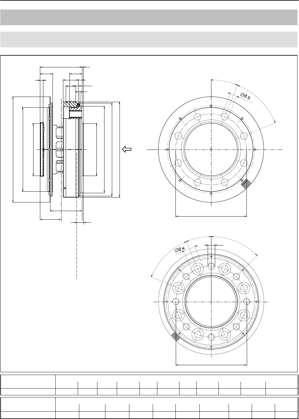
T12
70
A1979−10.0 enHBM
16 Dimensions
16.1 Rotor 100 NVm to 200 NVm
dz
dc
dzi
dza
dF
dG
dA
dB
dB
A
View A
6xY
b2c
b3
b1
b3
b5
b4
b6
xS
Dimensions without tolerances, per DIN ISO 2768−mK
5
2
Plane of temperature
measurement
d
b7
xS = measuring plane
(center of the installation point)
6x60
30
60
6x60
30
60
6x60
Measuring range Dimensions in mm (1 mm = 0.03937 inches)
b1b2b3b4b5b6b7c d xSY
100 Nm/200 Nm 22 60 18 4 4 47.15 14 2 12.5 30 M8
Measuring range Dimensions in mm (1 mm = 0.03937 inches)
dAdBdCdFdGdKdSC12 dZdza g5 dzi H6
100 Nm/200 Nm115.5 84 99 101 110 14 8.2 131 57 57
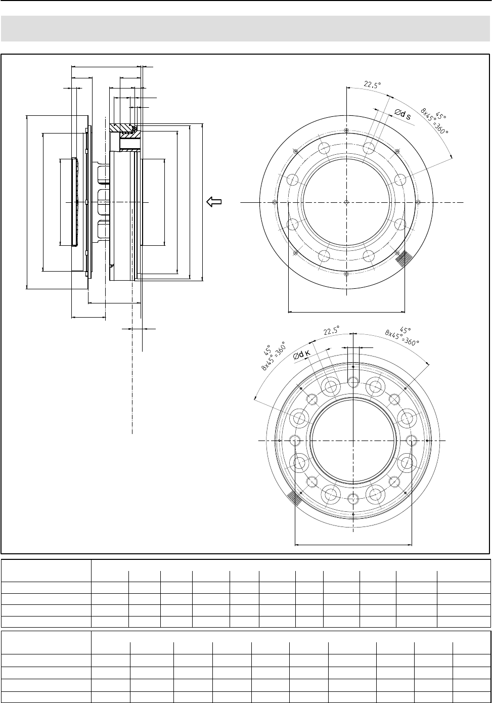
71
T12
A1979−10.0 en HBM
16.2 Rotor 500 NVm to 10 kNVm
dz
dc
dzi
dza
dF
dG
dA
dB
dB
A
View A
8xY
b2c
b3
b1
b3
b5b4
b6
xs
Dimensions without tolerances, per DIN ISO 2768−mK
5
b72
Plane of temperature
measurement
d
xs = measuring plane
(center of the
installation point)
Measuring range Dimensions in mm (1 mm = 0.03937 inches)
b1b2b3b4b5b6b7c d xSY
500 Nm/1 kNm 22 60 18 4 4 45.7 14 2 8 30 M10
2 kNm/3 kNm 23 64 20 5 4 47.7 14 2.5 8 32 M12
5 kNm 24.8 84 26 3.3 3 62.7 17.5 2.8 8 42 M14
10 kNm 24.8 92 30 3.3 4 66.7 17.5 3.5 10 46 M16
Measuring range Dimensions in mm (1 mm = 0.03937 inches)
dAdBdCdFdGdKdSC12 dZdza g5 dzi H6
500 Nm/1 kNm136.5 101.5 120 124 133 17 10 151 75 75
2 kNm/3 kNm172.5 130 155 160 169 19 12 187 90 90
5 kNm200.5 155.5 179 188 197 22 14.2 221 110 110
10 kNm242.5 196 221 230 239 26 17 269 140 140
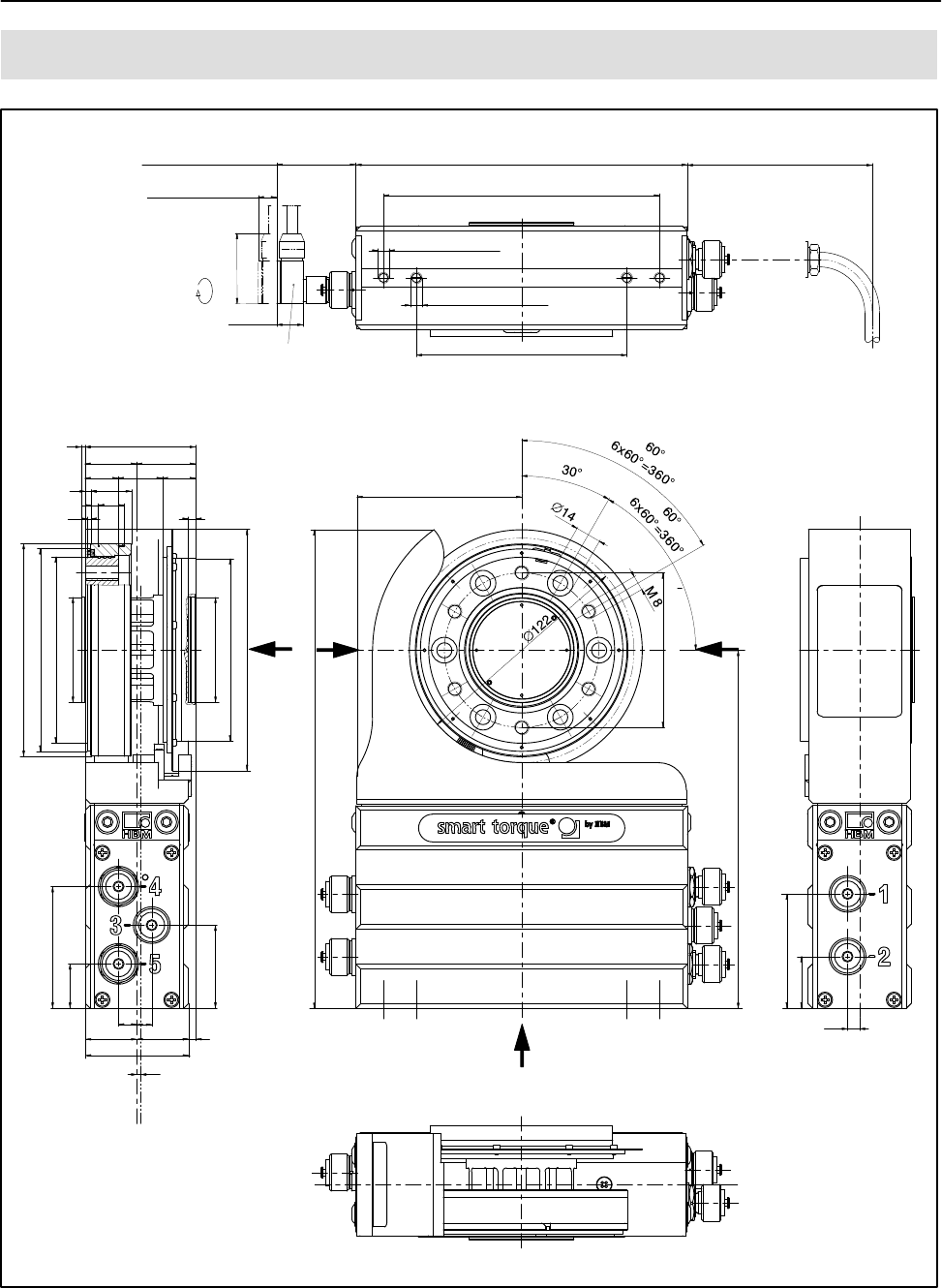
T12
72
A1979−10.0 enHBM
16.3 Stator 100 Nm to 200 Nm with rot.speed meas. system
28
10
115.5
14
22
18
32
approx. V20
ACCESSORIES !
Cable socket 7-pin and
8-pin 90 cable routing
min. 43
Reserved additional space for
connected state min. 10
Reserved additional
space for mounting
and dismounting
Cable socket
adjustable in 4
angular positions
approx. 54
180
150
M6
max. thread reach 10+1
UNF 1/4max.
thread reach 0.4+0.02
114.3 = 4 1/2
approx. 100
Reserved additional space for
connection cable with plug
602
(28)
24 (18)
3
24
4
110
101
57 g5
57 H6
99
131
45
66
24
8
(28) 4
2
56
89.5
260
194.5
84
6.5
62
28
XY
Z
View Z
Side view X
Side view Y
Top view
A
Dimensions in mm (1 mm = 0.03937 inches)
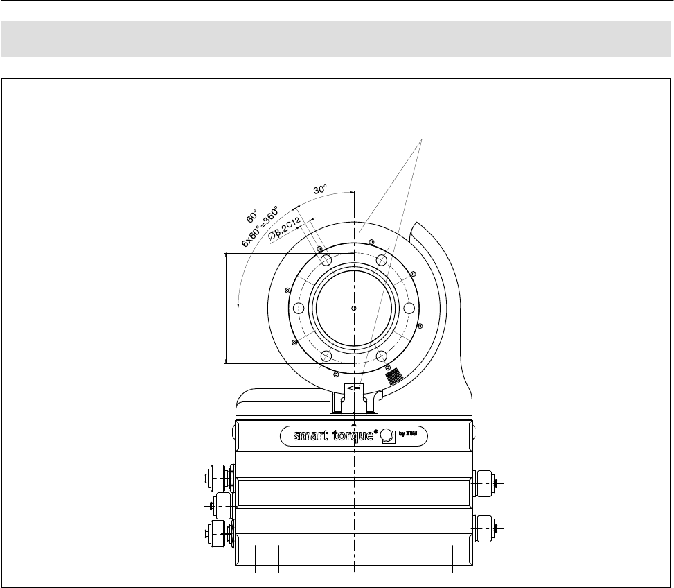
73
T12
A1979−10.0 en HBM
16.4 Stator 100 Nm to 200 Nm with rot. speed meas. system
For rotational speed
measuring system and
rotational speed
measuring system with
reference marker only
84
View A
Dimensions in mm (1 mm = 0.03937 inches)
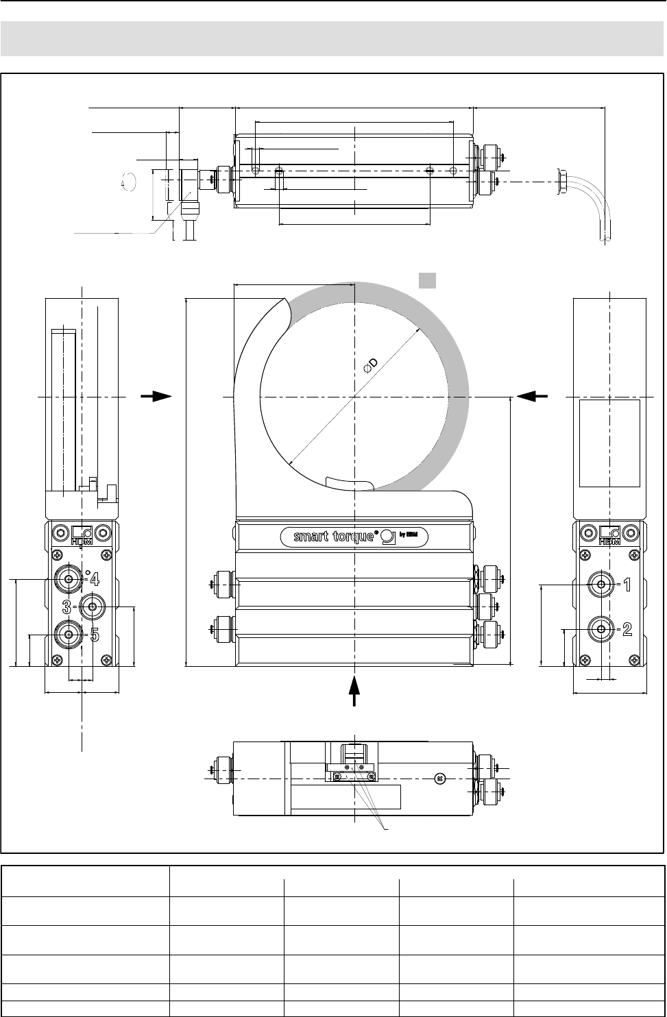
T12
74
A1979−10.0 enHBM
16.5 Stator 100 Nm to 10 kNm with rot. speed meas. system
b
H1
H2
180
150
66
24
45
28 (28)
10 8
28
56
6.5
For rotational speed measuring system and rotational
speed measuring system with reference marker only
approx. 100
min. 43
Reserved additional
space for connected state min. 10*)
Reserved additional space for
mounting and dismounting
approx. 20
approx.
54
Cable socket adjustable
in 4 angular positions
Accessories
Cable socket 7-pin and 8-pin
90 cable routing
Reserved additional
space for connection
cable with plug
114.3 = 4 1/2”
UNF 1/4”
Maximum thread reach 0.4” +0.02”
M6
Maximum thread reach 10 +1
Dimensions without tolerances, per DIN ISO 2768−mK
Side view Y Side view X
Top view
View Z
Y
X
Z
Air gap area:
Radially = 10 mm
Axially = b2 (see page 70)
62
Stator
mid−point
*) At 5 kNm and 10 kNm: min. 14 mm
Dimensions in mm (1 mm = 0.03937 inches)
Measuring range Dimensions in mm (1 mm = 0.03937 inches)
(NVm) bD H1 H2
100 81 122 260 194.5
200
500 91.5 143 280 204.5
1 k
2 k 109.5 179 310 222.5
3 k
5 k 123.5 207 333 239.5
10 k 144.5 249 369 263.5
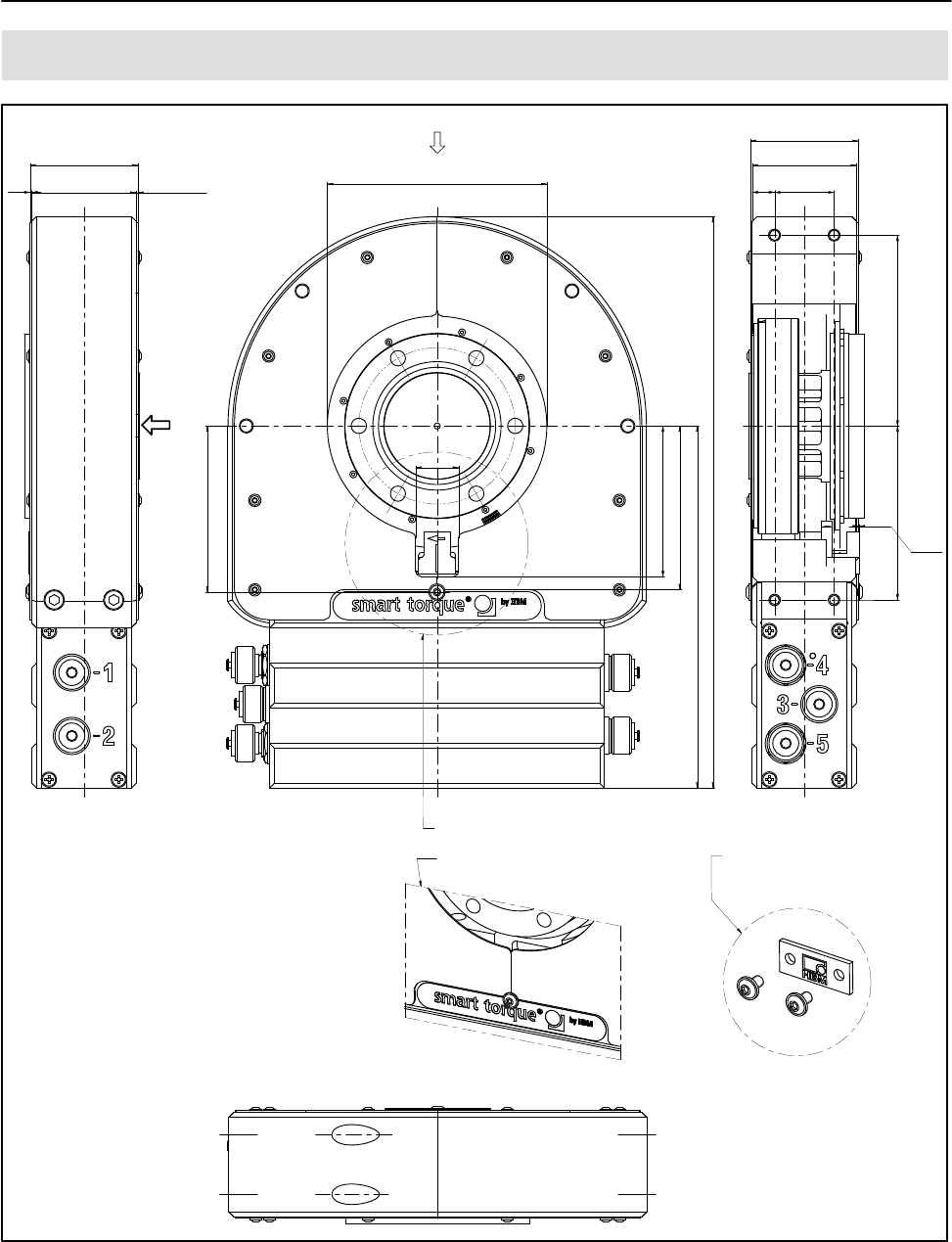
75
T12
A1979−10.0 en HBM
16.6 Stator 100 Nm to 200 Nm with prot. against contact
Cutaway dimension (in rotational speed
measuring system only) and without
cutaway in the standard version (without
rotational speed measuring system)
Part of the standard version!
The components on both sides
must be removed to mount the
protective housing.
Rotational speed
sensor [projection]
[Housing]
1
[Covering agent]
1
[Covering agent]
58
[Protection against contact cpl.]
56
[Housing]
58
[Protection against contact cpl.]
56
3212
102.5
93.5
0.55
View without housing half
118
307
88
194.5
89.3
[Locking screw]
81
23
B
A
View A
Dimensions in mm (1 mm = 0.03937 inches)
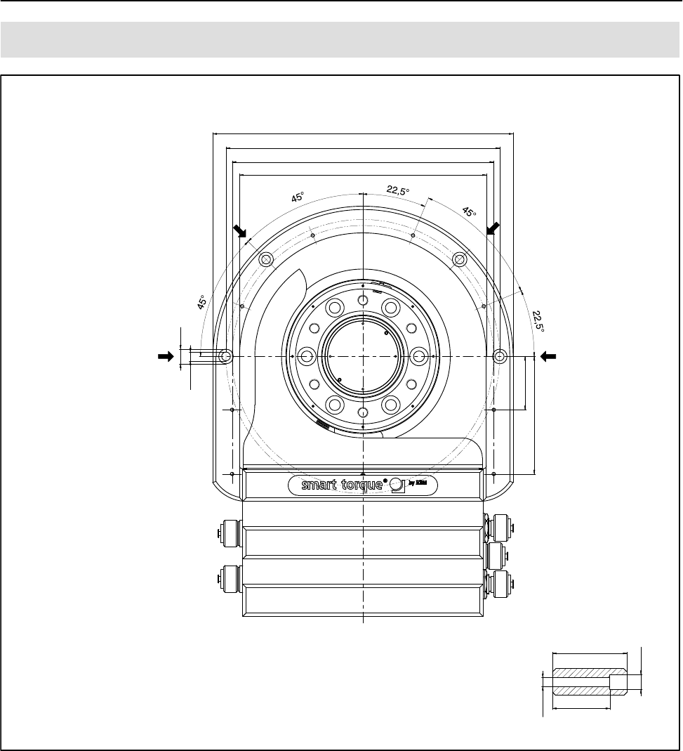
T12
76
A1979−10.0 enHBM
16.7 Stator 100 Nm to 200 Nm with prot. against contact
6.6
11
225+2
205
196
185−2
40
88
View without covering agent
(11)
(6.6)
56
[Housing]
43
Connecting hole with countersinking
Z
ZZ
Z
Connection holes Z
View B
Dimensions in mm (1 mm = 0.03937 inches)
77
T12
A1979−10.0 en HBM
16.8 Stator 500 Nm to 1 kNm with prot. against contact
A
View A
Connection holes Z
(Protection
against contact)
View without cover plate
Protection
against contact
Connecting hole with countersinking
(56)
43
6.6
(Protection against contact, cpl.)
View without
protection against
contact half
(Cover plate)
58
11
(Cover plate)
56 139
(56)
(58)
11
12 32
103.5 102.5
204.5
317
98
11
99.3
(Locking screw)
Z
Z
Z
Z
223+2
205
187−2
11
6.6
196
40
90
98
Dimensions in mm (1 mm = 0.03937 inches)
T12
78
A1979−10.0 enHBM
16.9 Stator 2 kNm to 10 kNm with prot. against contact
Connection holes Z
View A
A
Z
Z
Z
Z
(Housing)
View without protection against contact half
View without cover plate
Protection against
contact
Connecting hole with countersinking
(Cover plate) (Cover plate) d1
b2
b3b3
b1
b4
b2
b5
H1
H2
H3
H4 H5
d2
d3
d4
b2
b1
b8
11
6.6
(6.6)
(11)
b6b7
H6
d5
H7
b9
(Locking screw)
Measuring range Dimensions in mm (1 mm = 0.03937 inches)
b1b2b3b4b5b6b7b8b9H1H2H3H4H6H5H7
2 kNm/3 kNm 58 56 1 2 4 12 32 43 97.5 116 222.5 353 121.5 107 120.5 117.3
5 kNm 80 78 1 2 2 12 32 65 99 133 239.5 384 138.5 120 134.5 134.3
10 kNm 88 86 1 2 2 12 32 73 99 157 263.5 429 162.5 145 155.5 158.3
Measuring range Dimensions in mm (1 mm = 0.03937 inches)
d1d2d3d4d5
2 kNm/3 kNm 175 259+2 241 232 223−2
5 kNm 203 289+2 269 260 249−2
10 kNm 245 331+2 311 302 291−2
79
T12
A1979−10.0 en HBM
16.9.1 Protection against contact plates 100 Nm to 200 Nm
M3 screw head
M4 screw head
[Locking screw]
1:4
External = 7
Height = 2
External = 9
Height = 2.5
Dimensions in mm (1 mm = 0.03937 inches)
16.9.2 Protection against contact plates 500 Nm to 10 kNm
Spacing bolts for 5 kN@m
and 10 kN@m only
Screw head
(locking screw)
External = 9
Height = 2.5
External = 7
Height = 2
Screw head
Dimensions in mm (1 mm = 0.03937 inches)
b
Rotor
mid-point
Stator
mid-point
c
a
(Tolerance "1 mm)
Reserved add. space for fieldbus connection
cables:
approx. 140 mm, from plug connection tag
T12
80
A1979−10.0 enHBM
16.10 Mounting dimensions
Mounting dimensions
Measuring
range
Mounting dimension (mm)
a b c
100 Nm4 0 2
200 Nm
500 Nm2 2 0
1 kNm
2 kNm5 3 1
3 kNm
5 kNm 25 3 11
10 kNm 33 3 15
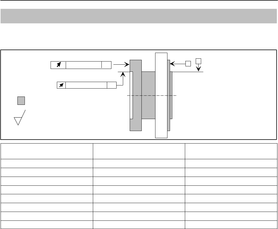
81
T12
A1979−10.0 en HBM
17 Supplementary technical information
Axial and radial run-out tolerances
Internal
centering
A
Axial run-out AB B
Hardness 46 to 54 HRC
Surface quality of the axial and radial
run-out tolerances (A, B and AB)
0.8
Radial run-out AB
Measuring range (NVm) Axial run-out tolerance (mm) Radial run-out tolerance
(mm)
100 0.01 0.01
200 0.01 0.01
500 0.01 0.01
1 k 0.01 0.01
2 k 0.02 0.02
3 k 0.02 0.02
5 k 0.025 0.025
10 k 0.025 0.025

T12
82
A1979−10.0 enHBM
18 Condition at the time of delivery
Parameter factory settings are marked with an asterisk (*). Underlined
parameters are not overwritten by returning to the factory settings.
SYSTEM
Default settings
Project name My Project
Language Deutsch; English
Define pass code (1 – 9999) 0
Pass code active? Yes*; No
Reactivate pass code Reactivate pass code
LED display mode Standard (measuring mode)
Rotor clearance setting mode
Opt. rotational speed measuring system setting
mode
Fieldbus interfaces
CANopen
CAN address 110
CAN baud rate 100 kB; 125 kB; 250 kB; 500 kB; 1000 kB*
LSS manufacturer number 285
LSS product number 1025
LSS revision number 4294967040
LSS serial number 4294967040
PDO measuring rate divider 1; 2*; 4; 8; 16; 32; 64
Signal PDO 1 (transmit, max.
4.8 kHz)
Off
Torque low pass 1*
Torque + rotational speed low pass 1
Torque low pass 1 + angle of rotation
Signal PDO 2 (transmit, max.
1.2 kHz)
Off
Torque low pass 2*
Torque + rotational speed low pass 2
Signal PDO 3 (transmit, max.
0.6 kHz)
Off*
Power + rotor temperature
Signal PDO 4 (transmit, max.
0.6 kHz)
Off*
Status for torque, rotational speed/angle of
rotation
Write calibration information
Torque calibration date
(dd.mm.yyyy)
30.11.06
Torque calibration initials RH
Torque calibration cycle 0
Measuring point number 0
Calibration date for rotational
speed/angle of rotation output
(dd.mm.yyyy)
30.11.06

83
T12
A1979−10.0 en HBM
Calibration initials for rotational
speed/angle of rotation output
KM
Calibration cycle for rotational
speed/angle of rotation output
0
Measuring point number 0
Voltage calibration date
(dd.mm.yyyy)
30.11.06
Voltage calibration initials HM
Voltage calibration cycle 0
Measuring point number 0
Pass code input
Enter pass code (1 – 9999) 0
TRANSDUCER PARAMETERIZATION
Torque
Measuring point designation MyTorqueMeasPnt
Measuring point number 0
Unit Nm*; kNm; ozfin; ozfft; lbfin; lbfft
Decimal point .; .0; .00; .000*; .0000; .00000
Sign Positive*; negative
Low pass filter 1
(nominal (rated) value)
0.05 Hz; 0.1 Hz; 0.2 Hz; 0.5 Hz; 1 Hz; 2 Hz; 5 Hz;
10 Hz; 20 Hz; 50 Hz; 100 Hz; 200 Hz; 500 Hz;
1 kHz*; 2 kHz; 4 kHz
Low pass filter 2
(nominal (rated) value)
0.05 Hz; 0.1 Hz; 0.2 Hz; 0.5 Hz; 1 Hz*; 2 Hz; 5 Hz;
10 Hz; 20 Hz; 50 Hz; 100 Hz
Measure point 1 Measure point 1
Actual value of physical point 1 0.000*
Setpoint (value) of physical point 1 0.000*
Measure point 2 Measure point 2
Actual value of physical point 2 100.000*
Setpoint (value) of physical point 2 100.000*
2-point scaling Active; deactivated*
Rotational speed
Unit 1/min*; rpm; 1/s; rad/s
Decimal point .; .0; .00; .000*
Sign Positive*; negative
Low-pass filter 1
(nominal (rated) value)
0.05 Hz; 0.1 Hz; 0.2 Hz; 0.5 Hz; 1 Hz; 2 Hz; 5 Hz;
10 Hz; 20 Hz; 50 Hz; 100 Hz; 200 Hz; 500 Hz; 1
kHz*; 2 kHz; 4 kHz
Low-pass filter 2
(nominal (rated) value)
0.05 Hz; 0.1 Hz; 0.2 Hz; 0.5 Hz; 1 Hz*; 2 Hz; 5 Hz;
10 Hz; 20 Hz; 50 Hz; 100 Hz
Angle of rotation
Unit Degree*; rad
Decimal point .; .0*; .00
Signal for zero balance Rotational speed sensor* (with reference signal);
Command* (without reference signal)

T12
84
A1979−10.0 enHBM
Rotational speed/angle of rotation output
Measuring point designation MySpeedMeasPnt
Measuring point number 0
Mechanical increments 360*/720*
Signals F1/ F2 Frequency*
Pulse (pos. edge)/direction of rotation
Pulse (pos./neg. edge)/direction of rotation
Pulse (4 edges)/direction of rotation
Output pulse division 1*; 2; 4; 6; 8; 12
Increments per revolution 360*/720*
Hysteresis for reversing the
direction of rotation
On*; Off
Frequency output
Signal Torque low pass 1*
Torque low pass 2
Mode 10 +/− 5 kHz*
60 +/− 30 kHz*
Setpoint (value) of physical point 1 0.000* (dep. on nominal (rated) measuring range)
Setpoint (value) of physical point 2 1000.000* (dep. on nominal (rated) measuring range)
Frequency of point 1 10.000000* (dep. on electrical configuration)
Frequency of point 2 15.000000* (dep. on electrical configuration)
Analog output
Signal Torque low pass 1*
Torque low pass 2
Rotational speed low pass 1
Rotational speed low pass 2
Measuring point number 0
Mode 10 V*
Setpoint (value) of physical point 1 0.000*
Setpoint (value) of physical point 2 1000.000*
Voltage of point 1 0.0000*
Voltage of point 2 10.0000*
Power
Unit W; kW*; MW; hp
Decimal point .; .0; .00; .000*
Low pass filter (−1 dB) 0.1 Hz; 1 Hz*; 10 Hz; 100 Hz
SIGNAL CONDITIONING
Torque
Shunt On; Off*
Shunt signal (of nominal (rated)
value)
10%; 50%*
Zero signal compensation Zero signal compensation
Zero value 0.000*

85
T12
A1979−10.0 en HBM
Angle of rotation
Measuring range 0 to n x 360 degrees, pos. direction of rotation*
0 to n x 360 degrees, neg. direction of rotation
0 to −n x 360 degrees, pos. direction of rotation
0 to −n x 360 degrees, neg. direction of rotation
−n x 360 to n x 360 degrees, pos. direction of
rotation
−n x 360 to n x 360 degrees, neg. direction of
rotation
Number of revolutions n 1*; 2; 3; 4
ADDITIONAL FUNCTIONS
Limit values
Limit value 1
Monitoring On; Off*On; Off*
Signal Torque low pass 1*
Torque low pass 2
Rotational speed low
pass 1*
Rotational speed low
pass 2
Switching direction Overshoot*
Undershoot
Overshoot*
Undershoot
Level 10.000*10.0*
Hysteresis 0.500*0.5*
Limit value 2
Monitoring On; Off*On; Off*
Signal Torque low pass 1*
Torque low pass 2
Rotational speed low
pass 1*
Rotational speed low
pass 2
Switching direction Overshoot*
Undershoot
Overshoot*
Undershoot
Level 10.000*10.0*
Hysteresis 0.500*0.5*
Limit value 3
Monitoring On; Off*On; Off*
Signal Torque low pass 1*
Torque low pass 2
Rotational speed low
pass 1*
Rotational speed low
pass 2
Switching direction Overshoot
Undershoot*
Overshoot
Undershoot*
Level −10.000*−10.0*
Hysteresis 0.500*0.5*
Limit value 4
Monitoring On; Off*On; Off*
Signal Torque low pass 1*
Torque low pass 2
Rotational speed low
pass 1*
Rotational speed low
pass 2

T12
86
A1979−10.0 enHBM
Switching direction Overshoot
Undershoot*
Overshoot
Undershoot*
Level −10.000*−10.0*
Hysteresis 0.500*0.5*
SAVE/LOAD PARAMETERS
Load from transducer
Choose parameter set 1*; 2; 3; 4; factory settings
Save to transducer
Choose parameter set 1; 2; 3; 4
TEDS template for torque HBM Frequency Sensor*
High Level Voltage Output
Rotational speed/angle of rotation
output
HBM Frequency Sensor*
HBM Pulse Sensor
87
T12
A1979−10.0 en HBM
19 Ordering numbers
LDependent on meas. range up to 15 000 rpm
Order no.:
K-T12 −
Ordering example:
K-T12 −SF 1C
500Q
Code Option 1: measuring range
S002R 2 kNm
S003R 3 kNm
Code Option 7: protection against contact
Without protection against contact
Code Option 2: accuracy
S Standard
G
"
Greater accuracy1)
Lin. t"0.01% and TK0 t"0.01%/10 K
L
Code Option 6: rotational speed measuring system
1With optical rotational speed measuring system;
360 or 720 pulses/revolution
With optical rotational speed measuring system;
360 or 720 pulses/revolution and reference signal
NWithout rotational speed measuring system
Code Option 5: bus connection
PCANopen and Profibus DPV1
CCANopen (2 device plugs)
1
N
S
Code Option 3: nominal (rated) rotational speed
HDependent on meas.range up to 18 000 rpm
S001R 1 kNm
S500Q 500 Nm
Code Option 4: electrical configuration
DF1 Output signal 60 kHz "30 kHz
DU2 Output signal 60 kHz "30 kHz and
"10 V
SF1 Output signal 10 kHz "5 kHz
SU2 Output signal 10 kHz "5 kHz and
"10 V
With protection against contactY
N
Code Option 8: MODULFLEX) coupling2)
Without couplingN
With fitted coupling
N
A
Y
11) For voltage output: lin. t"0.05% ;
TK0 t"0.1%/10 K
2) For Option 3, code L only; see
data sheet B1957-xx de for
specifications.
S
Code Option 9: Customized modification
No customized modificationN
N
S005R 5 kNm
S010R 10 kNm
S200Q 200 Nm
S100Q 100 Nm

T12
88
A1979−10.0 enHBM
20 Accessories
Article Order no.
Connection cable, set
Torque
Torque connection cable, Binder 423 7pin-D-Sub 15-pin, 6 m 1−KAB149−6
Torque connection cable, Binder 423 free ends, 6 m 1−KAB153−6
Rotational speed
Torque connection cable, Binder 423 8-pin-D-Sub 15-pin, 6 m 1−KAB150−6
Rotational speed connection cable, Binder 423 8-pin free ends, 6 m 1−KAB154−6
Rotational speed connection cable, reference signal, Binder 423
8-pin-D-Sub 15-pin, 6 m
1−KAB163−6
Rotational speed connection cable, reference signal, Binder 423 8-pin
free ends, 6 m
1−KAB164−6
CAN Bus
CAN Bus M12 connection cable, A-coded, D-Sub 9-pin, switchable
termination resistor, 6 m
1−KAB161−6
Plugs/sockets
Torque
423G−7S, 7-pin cable socket, straight cable entry, for torque output
(plug 1, plug 3)
3−3101.0247
423W−7S, 7-pin cable socket, 90 cable entry, for torque output (plug 1,
plug 3)
3−3312.0281
Rotational speed
423G−8S, 8-pin cable socket, straight cable entry, for rotational speed
output (plug 2)
3−3312.0120
423W−8S, 8-pin cable socket, 90cable entry, for rotational speed
output (plug 2)
3−3312.0282
CAN Bus
TERMINATOR M12/termination resistor, M12, A-coded, 5-pin, plug 1−CANHEAD−TERM
Termination resistor, CAN Bus M12, A-coded, 5-pin, socket 1−CAN−AB−M12
T-SPLITTER M12/T-piece M12, A-coded, 5-pin 1−CANHEAD−M12−T
Cable plug/socket/CAN Bus M12, cable socket 5-pin M12, A-coded,
cable plug 5-pin M12, A-coded
1−CANHEAD−M12
PROFIBUS
Connection cable, Y-splitter, M12 socket, B-coded; M12 plug, B-coded;
M12 socket, B-coded, 2 m
1−KAB167-2
Cable plug/socket/PROFIBUS M12, cable socket 5-pin M12, B-coded,
cable plug 5-pin M12, B-coded
1−PROFI−M12
Termination resistor PROFIBUS M12, B-coded, 5-pin 1−PROFI−AB−M12
T-piece PROFIBUS M12,B-coded, 5-pin 1−PROFI−VT−M12
Connection cable, by the meter
Kab8/00−2/2/2 4−3301.0071
Kab8/00−2/2/2/1/1 4−3301.0183
DeviceNet cable 4−3301.0180
Other
Setup toolkit for T12 (System CD T12, PCAN-USB adapter, CAN Bus
connection cable, 6 m)
1−T12−SETUP−USB

89
T12
A1979−10.0 en HBM

T12
90
A1979−10.0 enHBM

A1979−10.0 en 7−2002.1979
Hottinger Baldwin Messtechnik GmbH
Im Tiefen See 45 S 64293 Darmstadt S Germany
Tel. +49 6151 803−0 S Fax: +49 6151 803−9100
Email: info@hbm.com S www.hbm.com
measure and predict with confidence
E Hottinger Baldwin Messtechnik GmbH.
Subject to modifications.
All details describe our products in general form only.
They are not to be understood as a guarantee of quality or durability.