Hottinger Bruel and Kjaer T40S0TOS1 T40 Torquemeter User Manual Mounting instructions T40HS en V1
Hottinger Baldwin Messtechnik GmbH T40 Torquemeter Mounting instructions T40HS en V1
UserManual.wiki
>
Hottinger Bruel and Kjaer
>
T40S0TOS1 User Manual
User Manual
Navigation menu
Upload a User Manual
Namespaces
Wiki Guide
HTML
PDF
Info
Views
User Manual
Discussion / Help
Navigation
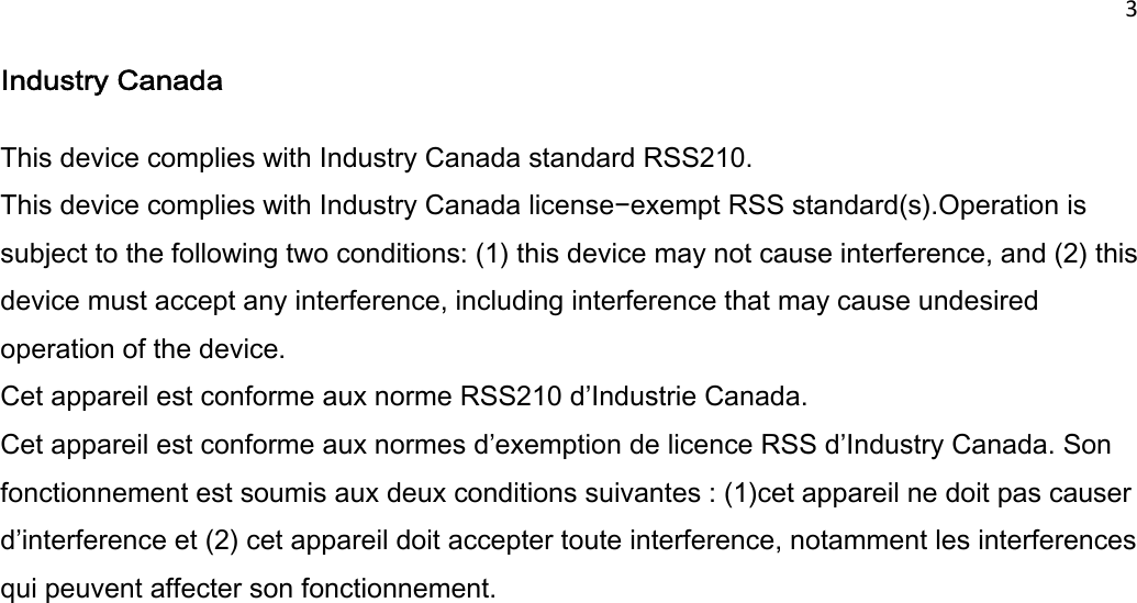
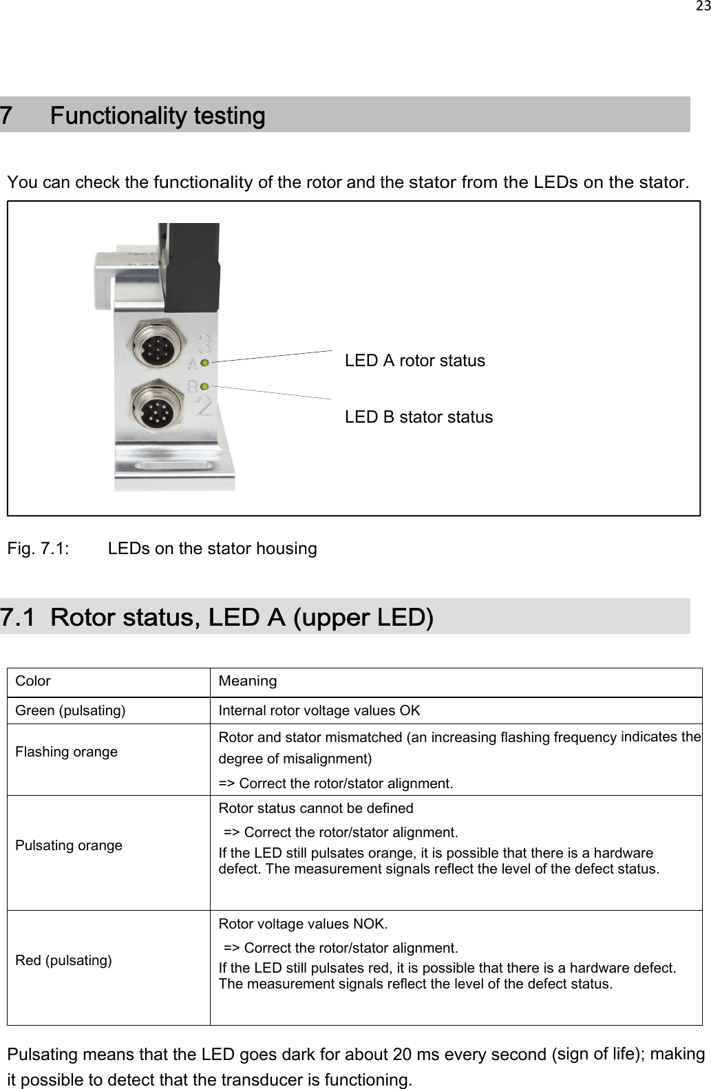
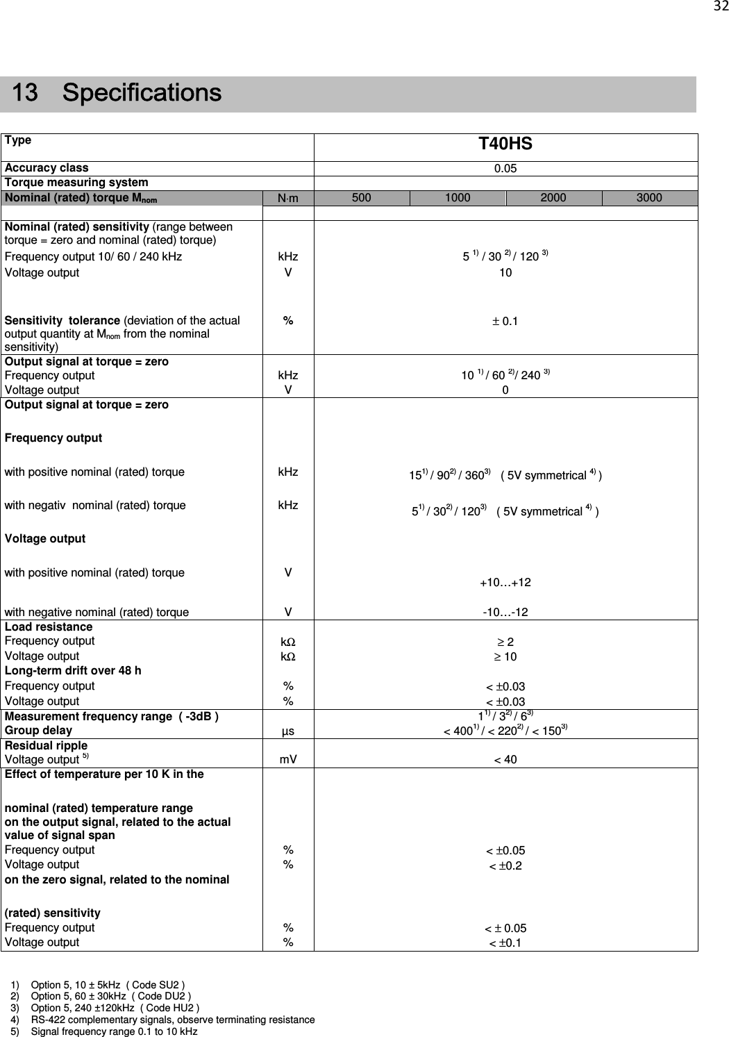
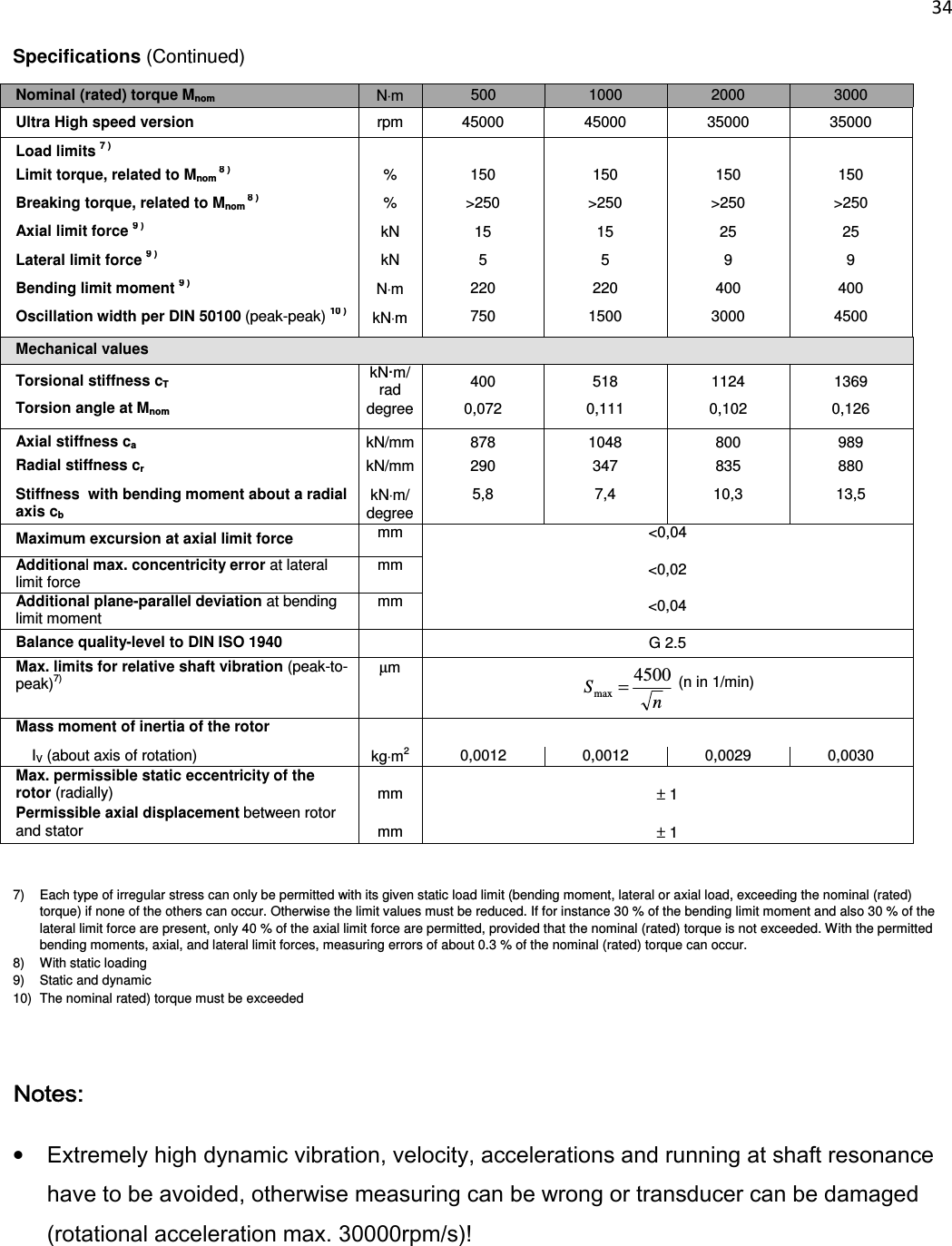
![33 Specifications (Continued) Nominal (rated) torque Mnom N⋅m 500 1000 2000 3000 Max. modulation range6) Frequency output kHz 2.5 … 17.51) / 15 … 1052) / 60 … 4203) Voltage output V -12 -12 Power supply Nominal supply voltage (protective low voltage) V 18 ... 30; asymmetric Current consumption in measuring mode A < 1 (typ.0.5) Current consumption in start-up mode A < 4 (50 µs) Nominal (rated) power consumption W < 10 Maximum cable length m 50 Non-Linearity including hysteresis, relativ to the nominal (rated) sensitivity Frequency output % < ±0.05 Voltage output % < ±0.05 Relativ standard deviation of repeatability per DIN1319, relativ to the vari. of output signal Frequency output % < ±0.03 Voltage output % < ±0.03 Shunt signal approx. 50 % of Mnom; value given to the identification plate Tolerance of calibration signal related to Mnom % < ±0.05 General data EMC Emission (per EN 61326-1, EN 61326-2-3) Radiated emmissions (according to EN 55011) - Interference immunity (per EN61326-2-3) Electromagnetic field AM Magnetic field V/m A/m Electrostatic discharge (ESD) Contact discharge kV Air discharge Rapid transients (burst) Impulse voltages (surge) Conducted interference (AM) kV kV kV V Degree of protection according to EN 60529 IP 54 Weight, Rotor approx. kg 0,83 0,85 1,51 1,55 Stator approx. kg 1,1 1,1 1,1 1,1 Reference temperature °C [°F] +23 [+73,4] Nominal temperature range °C [°F] +10...+70 [+50...+158] Service temperature range °C [°F] -10...+70 [+14...+158] Storage temperature range °C [°F] -20...+85 [-4...+185] 6) Output signal range with a repeatable interrelationship between torque and output signal.](https://usermanual.wiki/Hottinger-Bruel-and-Kjaer/T40S0TOS1/User-Guide-2840747-Page-37.png)