Hottinger Bruel and Kjaer T40S10TOS11 T40-S10TOS11 Torquemeter User Manual A3276 T40FM
Hottinger Baldwin Messtechnik GmbH T40-S10TOS11 Torquemeter A3276 T40FM
User Manual
Mounting Instructions | Montageanleitung
English Deutsch
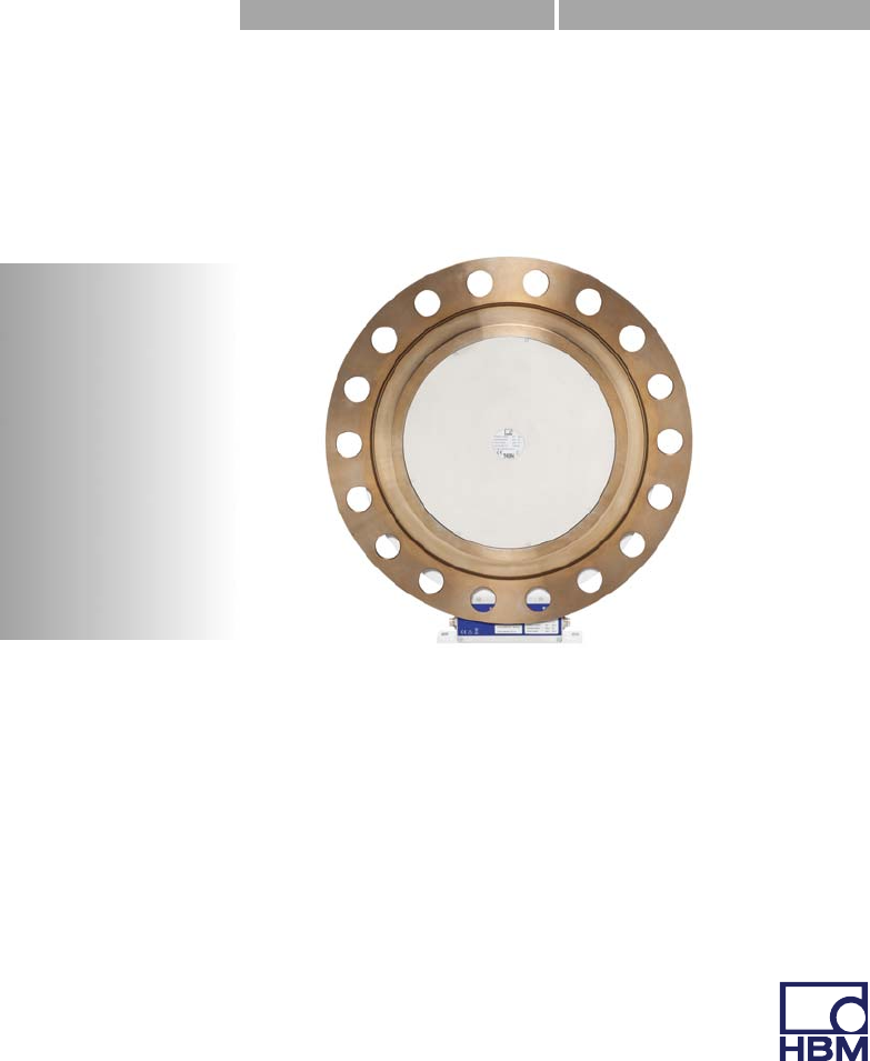
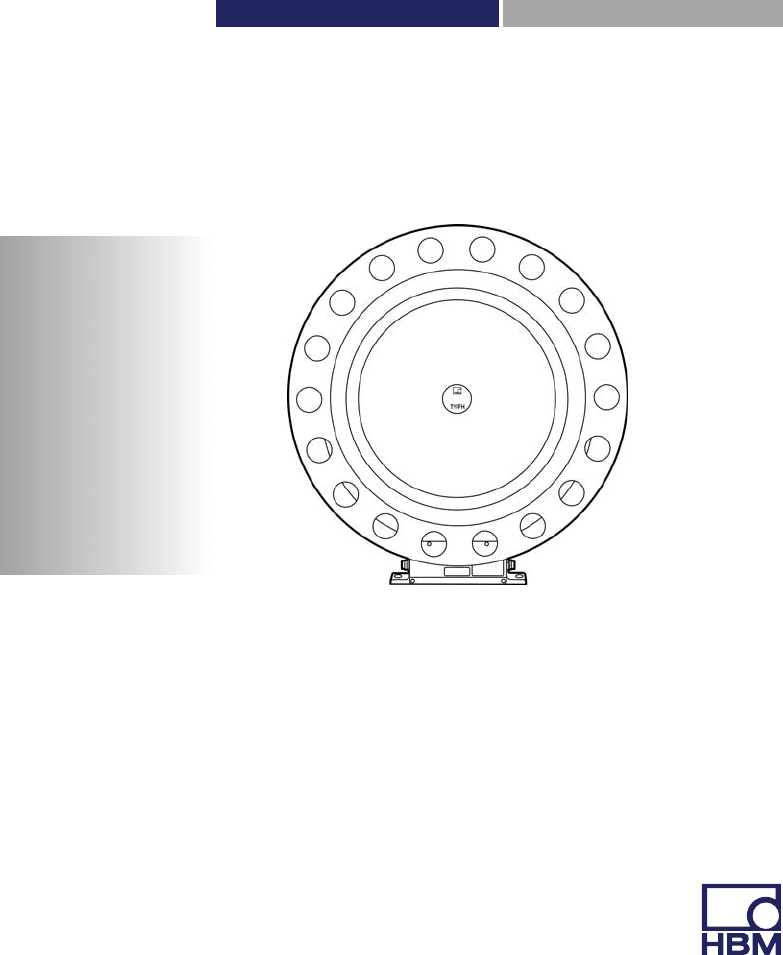
T40FH
Hottinger Baldwin Messtechnik GmbH
Im Tiefen See 45
D-64239 Darmstadt
Tel. +49 6151 803-0
Fax +49 6151 803-9100
info@hbm.com
www.hbm.com
Mat.: 7-2002.4429
DVS: A4429-1.0 HBM: public
02.2016
E Hottinger Baldwin Messtechnik GmbH.
Subject to modifications.
All product descriptions are for general information only.
They are not to be understood as a guarantee of quality or
durability.
Änderungen vorbehalten.
Alle Angaben beschreiben unsere Produkte in allgemeiner
Form. Sie stellen keine Beschaffenheits- oder Haltbarkeits
garantie dar.
Mounting Instructions | Montageanleitung
English Deutsch
T40FH

2A4429-1.0 HBM: public T40FH
English
1 Safety instructions 4........................................
2 Markings used 11............................................
2.1 Symbols on the transducer 11..................................
2.2 The markings used in this document 12..........................
3 Application 13...............................................
4 Structure and mode of operation 14...........................
5 Mechanical installation 16....................................
5.1 Important precautions during installation 16......................
5.2 Conditions on site 17..........................................
5.3 Mounting position 18..........................................
5.4 Installation options 18.........................................
5.4.1 Installation with antenna ring removed 19........................
5.5 Preparing for the rotor mounting 20.............................
5.6 Mounting the rotor 24..........................................
5.7 Installing the stator 27.........................................
5.8 Rotational speed measuring system 32..........................
6 Electrical connection 35......................................
6.1 General information 35........................................
6.2 EMC protection 35............................................
6.3 Connector pin assignment Option 4, Code SU2, DU2, HU2 37....
6.4 Connector pin assignment Option 3, Code PNJ 42................
6.5 Supply voltage (SU2, DU2, HU2) 42.............................
6.6 Supply voltage (Option 3, Code PNJ) 43.........................
7 TEDS transducer identification (Option 3, Code PNJ) 44.......
7.1 Hierarchy of user rights 44.....................................
7.1.1 Standard rights (USR level) 44.................................
7.1.2 Calibration rights (CAL level) 44................................

T40FH A4429-1.0 HBM: public 3
7.1.3 Administrator rights (ID level) 45................................
7.2 Contents of the TEDS memory as defined in IEEE 1451.4 45.......
8 Shunt signal 50..............................................
9 Functionality testing 51......................................
9.1 Rotor status, LED A (upper LED) 52.............................
9.2 Stator status, LED B (lower LED) 52............................
10 Load-carrying capacity 54....................................
11 Maintenance 56..............................................
12 Waste disposal and environmental protection 57..............
13 Dimensions 58..............................................
13.1 T40FH torque transducer with rotational speed measuring system,
Option 4, Code SU2, DU2, HU2 58.............................
13.1.1 T40FH 100kNm - 150kNm 58.................................
13.1.2 T40FH 200kNm - 300kNm 59.................................
13.2 T40FH torque transducer (non-rotating),
Option 4, Code PNJ 60.......................................
13.2.1 T40FH 100 kNm - 150 kNm 60.................................
13.2.2 T40FH 200kNm - 300kNm 61.................................
14 Ordering numbers, accessories 62............................
15 Specifications 64............................................
16 Supplementary technical information 72......................
Safety instructions
4A4429-1.0 HBM: public T40FH
1 Safety instructions
FCC conformity and notice
Information
FCC option only available on request.
Important
Any change or modification not expressly approved in
writing by the party responsible for conformity could void
the user's authority to operate this equipment. Where
indicated, additional components or accessories whose
use is prescribed elsewhere during installation of the
product must be used to ensure compliance with the FCC
Rules.
This device complies with Part 15 of the FCC Rules.
Operation is subject to the following two conditions: (1)
This device may not cause harmful interference and (2)
this device must accept any interference received, includ
ing interference that may cause undesired operation.
The FCC ID, that is to say, the unique identifier, must be
visible on the device.
Model Measuring ranges FCC ID IC
T40S10 100 kNm, 130
kNm, 150 kNm 2ADAT−T40S10TOS11 12438A−T40S10TOS11
T40S11 200 kNm, 250
kNm, 300 kNm
Safety instructions
T40FH A4429-1.0 HBM: public 5
Example of a label with FCC ID and IC number.
Identification
plate
Fig. 1.1 Position of the label on the device stator
Model: T40S10
FCC ID: 2ADAT-T40S10TOS11
IC: 12438AT40S10TOS11
This device complies with part 15 of the FCC Rules. Operation is
subject to the following two conditions: (1) This device may not
cause harmful interference, and (2) this device must accept any
interference received, including interference that may cause un
desired operation.
Fig. 1.2 Example of a label

Safety instructions
6A4429-1.0 HBM: public T40FH
This device complies with Industry Canada standard
RSS210.
This device complies with Industry Canada license‐ex
empt RSS standard(s).Operation is subject to the follow
ing two conditions: (1) This device may not cause harmful
interference, and (2) this device must accept any interfer
ence received, including interference that may cause un
desired operation.
Cet appareil est conforme aux norme RSS210 d’Industrie
Canada.
Cet appareil est conforme aux normes d’exemption de
licence RSS d’Industry Canada. Son fonctionnement est
soumis aux deux conditions suivantes : (1) cet appareil
ne doit pas causer d’interférence et (2) cet appareil doit
accepter toute interférence, notamment les interférences
qui peuvent affecter son fonctionnement.
Appropriate use
The T40FH torque flange is used exclusively for torque,
angle of rotation and power measurement tasks within
the load limits stipulated in the specifications. Any other
use is not appropriate.
Stator operation is only permitted when the rotor is
installed.
The torque flange may only be installed by qualified per
sonnel in compliance with the specifications and with the
safety requirements and regulations of these mounting
instructions. It is also essential to observe the applicable
legal and safety regulations for the application con
cerned. The same applies to the use of accessories.
The torque flange is not intended for use as a safety
component. Please also refer to the "Additional safety
precautions" section. Proper and safe operation requires

Safety instructions
T40FH A4429-1.0 HBM: public 7
proper transportation, correct storage, siting and mount
ing, and careful operation.
Load-carrying capacity limits
The data in the technical data sheets must be complied
with when using the torque flange. The respective speci
fied maximum loads in particular must never be
exceeded. The values stated in the technical data sheets,
forexample, must not be exceeded for
SLimit torque,
SLongitudinal limit force, lateral limit force or bending
limit moment,
STorque oscillation width,
SBreaking torque,
STemperature limits,
SLimits of the electrical load-carrying capacity.
Use as a machine element
The torque flange can be used as a machine element.
When used in this manner, it must be noted that, to favor
greater sensitivity, the transducer is not designed with the
safety factors usual in mechanical engineering. Please
refer here to the section "Load-carrying capacity limits",
and to the specifications.
Accident prevention
According to the prevailing accident prevention regula
tions, once the transducers have been mounted, a cover
ing agent or cladding has to be fitted as follows:
SThe covering agent or cladding must not be free to
rotate.

Safety instructions
8A4429-1.0 HBM: public T40FH
SThe covering agent or cladding should prevent
squeezing or shearing and provide protection against
parts that might come loose.
SCovering agents and cladding must be positioned at a
suitable distance or be so arranged that there is no
access to any moving parts within.
SCovering agents and cladding must still be attached
even if the moving parts of the torque flange are
installed outside peoples' movement and working
range.
The only permitted exceptions to the above requirements
are if the torque flange is already fully protected by the
design of the machine or by existing safety precautions.
Additional safety precautions
The torque flange cannot (as a passive transducer)
implement any (safety-relevant) cutoffs. This requires
additional components and constructive measures, for
which the installer and operator of the plant is responsi
ble. The electronics conditioning the measurement signal
should be designed so that measurement signal failure
does not subsequently cause damage.
The scope of supply and performance of the transducer
covers only a small area of torque measurement technol
ogy. In addition, equipment planners, installers and oper
ators should plan, implement and respond to safety engi
neering considerations in such a way as to minimize
residual dangers. Pertinent national and local regulations
must be complied with.

Safety instructions
T40FH A4429-1.0 HBM: public 9
General dangers of failing to follow the safety
instructions
The torque flange corresponds to the state of the art and
is failsafe. Transducers can give rise to residual dangers
if they are incorrectly operated or inappropriately
mounted, installed and operated by untrained personnel.
Every person involved with siting, starting-up, operating
or repairing a torque flange must have read and under
stood the mounting instructions and in particular the tech
nical safety instructions. The transducers can be dam
aged or destroyed by non-designated use of the
transducer or by non-compliance with the mounting and
operating instructions, these safety instructions or any
other applicable safety regulations (BG safety and acci
dent prevention regulations) when using the transducers.
Transducers can break, particularly in the case of over
loading. The breakage of a transducer can also cause
damage to property or injury to persons in the vicinity of
the transducer.
If the torque flange is not used according to the desig
nated use, or if the safety instructions or specifications in
the mounting and operating instructions are ignored, it is
also possible that the transducer may fail or malfunction,
with the result that persons or property may be affected
(due to the torques acting on or being monitored by the
torque flange).
Conversions and modifications
The design or safety engineering of the transducer must
not be modified without our express permission. Any
modification shall exclude all liability on our part for any
damage resulting therefrom.

Safety instructions
10 A4429-1.0 HBM: public T40FH
Selling on
If the torque flange is sold on, these mounting instruc
tions must be included with the torque flange.
Qualified personnel
Qualified personnel are persons entrusted with the setup,
mounting, startup and operation of the product, who have
the appropriate qualifications for their function.
This includes people who meet at least one of the three
following requirements:
1. Knowledge of the safety concepts of automation tech
nology is a requirement and as project personnel, you
must be familiar with these concepts.
2. As automation plant operating personnel, you have
been instructed how to handle the machinery. You are
familiar with the operation of the equipment and tech
nologies described in this documentation.
3. As commissioning engineers or service engineers,
you have successfully completed the training to repair
the automation systems. You are also authorized to
operate, ground and label circuits and equipment in
accordance with safety engineering standards.
Markings used
T40FH A4429-1.0 HBM: public 11
2 Markings used
2.1 Symbols on the transducer
Read and note the data in this manual
CE mark
The CE mark enables the manufacturer to guarantee that
the product complies with the requirements of the rele
vant EC directives (the Declaration of Conformity can be
found on the HBM website www.hbm.com under
HBMdoc).
Example of a label
Example of a label with FCC ID and IC number. Position
of the label on the device stator.
Statutory waste disposal mark
The electrical and electronic devices that bear this sym
bol are subject to the European waste electrical and elec
tronic equipment directive 2002/96/EC. The symbol indi
cates that, in accordance with national and local
environmental protection and material recovery and recy
cling regulations, old devices that can no longer be used
must be disposed of separately and not with normal
household garbage, see also Chapter 12, Page 57.
Model: T40S10
FCC ID: 2ADAT-T40S10TOS11
IC: 12438AT40S10TOS11
This device complies with part 15 of the
FCC Rules. Operation is subject to the fol
lowing two conditions: (1) This device may
not cause harmful interference, and (2)
this device must accept any interference
received, including interference that may
cause undesired operation.
Markings used
12 A4429-1.0 HBM: public T40FH
2.2 The markings used in this document
Important instructions for your safety are specifically iden
tified. It is essential to follow these instructions in order to
prevent accidents and damage to property.
Symbol Significance
WARNING This marking warns of a potentially dangerous situa
tion in which failure to comply with safety require
ments can result in death or serious physical injury.
CAUTION This marking warns of a potentially dangerous situa
tion in which failure to comply with safety require
ments can result in slight or moderate physical injury.
Notice This marking draws your attention to a situation in
which failure to comply with safety requirements can
lead to damage to property.
Important
This marking draws your attention to important infor
mation about the product or about handling the prod
uct.
Tip
This marking indicates application tips or other infor
mation that is useful to you.
Information
This marking draws your attention to information
about the product or about handling the product.
Emphasis
See …
Italics are used to emphasize and highlight text and
identify references to sections, diagrams, or external
documents and files.

Application
T40FH A4429-1.0 HBM: public 13
3 Application
The T40FH torque flange measures static and dynamic
torques on stationary and rotating shafts. Test beds can
be extremely compact because of the compact design of
the transducer. This offers a very wide range of applica
tions.
The T40FH torque flange is reliably protected against
electromagnetic interference. It has been tested in accor
dance with harmonized European standards and/or com
plies with US and Canadian standards. The CE mark
and/or the FCC label are attached to the product.

Structure and mode of operation
14 A4429-1.0 HBM: public T40FH
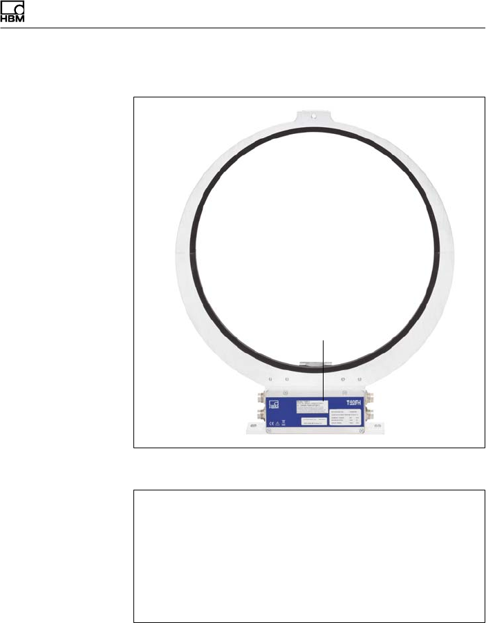
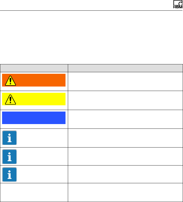
4 Structure and mode of operation
The torque flange consist of two separate parts: the rotor
and the stator. The rotor comprises the measuring body
and the signal transmission elements.
Strain gages (SGs) are installed on the measuring body.
The rotor electronics for transmitting the bridge excitation
voltage and the measurement signal are located centrally
in the flange. The transmitter coils for contactless trans
mission of excitation voltage and measurement signal are
located on the measuring body's outer circumference.
The signals are sent and received by a separable
antenna ring. The antenna ring is mounted on a housing
that includes the electronic system for voltage adaptation
and signal conditioning.
Connector plugs for the torque and rotational speed sig
nals, the voltage supply and the digital output are located
on the stator. The antenna segments (ring) should be
mounted concentrically around the rotor (see Chapter 5).
Structure and mode of operation
T40FH A4429-1.0 HBM: public 15
Antenna seg
ments
Rotor
Connector
plugs
Stator housing
Type plate
Connector plugs
Fig. 4.1 Mechanical construction
The rotational speed sensor is mounted on the stator in
Option 5 with a rotational speed measuring system. Rota
tional speed is measured magnetically by a magnetic
field dependent resistor and a ring gear attached to the
rotor.

Mechanical installation
16 A4429-1.0 HBM: public T40FH
5 Mechanical installation
5.1 Important precautions during
installation
Notice
A torque flange is a precision measurement element and
therefore needs careful handling. Dropping or knocking
the transducer may cause permanent damage. Make
sure that the transducer cannot be overloaded, including
while it is being mounted.
SHandle the transducer with care.
SCheck the effect of bending moments, critical rota
tional speeds and natural torsional vibrations, to pre
vent the transducer being overloaded by resonance
sharpness.
SMake sure that the transducer cannot be overloaded.
WARNING
There is a danger of the transducer breaking if it is over
loaded. This can cause danger for the operating person
nel of the system in which the transducer is installed.
Implement appropriate safety measures to avoid over
loads and to protect against resulting dangers.
SUse a threadlocker (medium strength, e.g. LOCTITE)
to glue the screws into the counter thread to exclude

Mechanical installation
T40FH A4429-1.0 HBM: public 17
prestressing loss due to screw slackening, in the
event of alternating loads.
SComply with the mounting dimensions to enable cor
rect operation.
An appropriate shaft flange enables the T40FH torque
flange to be mounted directly. It is also possible to mount
a joint shaft or relevant compensating element directly on
the rotor (using an intermediate flange when required).
Under no circumstances should the permissible limits
specified for bending moments, lateral and longitudinal
forces be exceeded. Due to the T40FH torque flange's
high torsional stiffness, dynamic shaft train changes are
kept to a minimum.
Important
Even if the unit is installed correctly, the zero point adjust
ment made at the factory can shift by up to approx. 0.5%
of the characteristic value. If this value is exceeded, we
advise you to check the mounting conditions. If the resid
ual zero drift when the unit is removed is greater than 1%
of the characteristic value, please send the transducer
back to the Darmstadt factory for testing.
5.2 Conditions on site
The T40FH torque flange must be protected against
coarse dirt particles, dust, oil, solvents and moisture.
There is wide ranging compensation for the effects of
temperature on the output and zero signals of the trans
ducer (see Chapter 15 “Specifications"). If there are no
static temperature ratios, for example, because of the
temperature differences between the measuring body

Mechanical installation
18 A4429-1.0 HBM: public T40FH
and the flange, the values given in the specifications can
be exceeded. In this case, ensure static temperature
ratios by cooling or heating, depending on the applica
tion. As an alternative, check if thermal decoupling is pos
sible, e.g. by means of heat radiating elements such as
multiple-disc couplings.
5.3 Mounting position
The torque flange can be mounted in any position.
With clockwise torque, the output frequency for Option 5,
code DU2 is 60 … 90 kHz (Option 5, Code SU2: 10 …
15kHz; Option HU2: 240 … 360kHz). In conjunction with
HBM amplifiers or when using the voltage output, a posi
tive output signal (0 V …+10 V) is present. In the case
of the rotational speed measuring system, an arrow is
attached to the stator housing to clearly identify the direc
tion of rotation: If the measurement flange moves in the
direction of the arrow, connected HBM measuring ampli
fiers deliver a positive output signal.
With the non-rotating version, there is a positive output
signal in mV/V for clockwise torque.
5.4 Installation options
As its diameter is less than the flange diameter of the
rotor, the antenna ring must be dismantled for mounting.
If access to the rotor in its installed state is difficult, we
recommend mounting the antenna ring beforehand. It is
essential in this case to comply with the notes on assem
bling the antenna segments (see Section 5.7).

Mechanical installation
T40FH A4429-1.0 HBM: public 19
5.4.1 Installation with antenna ring removed
Customer
mounting
1 Install the rotor
3 Remove one antenna segment
5 Align and fully assemble the stator
2 Fit the stator mounting
4 Fit the antenna segment around the shaft
train
6 Fit the clamp fixture
Support supplied by customer
Clamp fixture
Mechanical installation
20 A4429-1.0 HBM: public T40FH
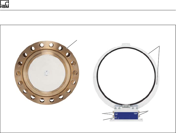
5.5 Preparing for the rotor mounting
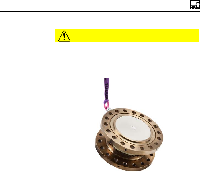
CAUTION
The rotor is heavy (as much as 142 kg, depending on the
measuring range)! Use a crane or other suitable lifting
equipment to lift it out of its packaging and install it.
When working with the crane, be sure to meet relevant
safety requirements and wear safety boots.
1. Remove the top layer of foam packaging.
Fig. 5.1 T40FH packaging
2. Fasten two equal-length ropes with sufficient load-car
rying capacity to the eyebolts (each of the two ropes
must be able to bear the full weight of the rotor) and

Mechanical installation
T40FH A4429-1.0 HBM: public 21
hoist the rotor out of its packaging with the crane (see
Fig. 5.2).
Fig. 5.2 Hoisting the rotor out of its packaging
3. Place the rotor on a clean and stable base.
4. Remove one of the eyebolts.
5. Carefully lift the rotor until it hangs free.
6. Carefully tilt the rotor by lowering it over the flange
edge until it rests horizontally on both outer flange sur
faces (see Fig. 5.3).
Mechanical installation
22 A4429-1.0 HBM: public T40FH
CAUTION
Crush hazard. Keep your hands and feet a safe distance
away from the rotor.
Fig. 5.3 Tilting the rotor
7. Secure the rotor with wedges to stop it from rolling
away.
8. Screw the second eyebolt back into the tapped holes
in the outer flange surface.
9. Fasten the rotor to the hook of the crane with two
equal-length ropes. The rotor is now prepared for hori
zontal installation (see Fig. 5.4).
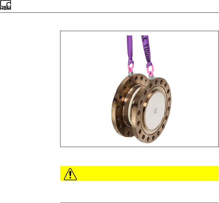
Mechanical installation
T40FH A4429-1.0 HBM: public 23
Fig. 5.4 Fastening for horizontal installation
CAUTION
You must remove the eyebolts after mounting! Keep
them safe for later use.

Mechanical installation
24 A4429-1.0 HBM: public T40FH
5.6 Mounting the rotor
Tip
Usually the rotor type plate is no longer visible after
installation. This is why we include with the rotor addi
tional stickers with the important characteristics, which
you can attach to the stator or any other relevant test-
bench components. You can then refer to them whenever
there is anything you wish to know, such as the shunt
signal. To explicitly assign the data, the identification
number and the size are engraved on the rotor flange,
where they can be seen from outside.
Notice
Make sure during installation that you do not damage the
measuring zone marked in Fig. 5.5 by using it to support
tools or knocking tools against it when tightening screws,
for example. This can damage the transducer and pro
duce measurement errors, or even destroy the trans
ducer.
1. Prior to installation, clean the plane faces of the trans
ducer flange and the counter flange.
For safe torque transfer, the surfaces must be clean
and free from grease. Use a piece of cloth or paper
soaked in solvent. When cleaning, make sure that you
do not damage the transmitter winding.

Mechanical installation
T40FH A4429-1.0 HBM: public 25
Hexagon socket screw (Z) DIN EN ISO 4762 (12.9)
Hexagon socket screw
(Z) DIN EN ISO 4762
(12.9)
Measuring
zone
Fig. 5.5 Bolted rotor connection
2. For connection of the flange, (see Fig. 5.5) use DIN
EN ISO 4762 property class 12.9 hexagon socket
screws of a suitable length (dependent on the
connection geometry, see Tab. 5.1 on Page 26).
We recommend DIN EN ISO4762 socket head cap
screws, blackened, smoothheaded, permitted size
and shape variance as per DIN ISO4759, Part 1,
product class A.
3. Fasten all screws with the specified torque (Tab. 5.1
on Page 26).
4. Now remove the ring bolts and mounting ring(s).
Important
Keep them in a safe place for future dismounting.
Mechanical installation
26 A4429-1.0 HBM: public T40FH
Important
Use a threadlocker (medium strength, e.g. LOCTITE) to
glue the screws into the counter thread to exclude pre
stressing loss due to screw slackening, in the event of
alternating loads.
Notice
Comply with the maximum thread reach as per Tab. 5.1,
Page 26. Otherwise significant measurement errors may
result from a torque shunt, or the transducer may be
damaged.
Measure
ment
range
Fastening screws Number of
screws per
flange
Prescribed
tightening moment
kNVm Z1) Property class NVm
100
150
150
M30
12.9
16 2450
200
250
300
M36 18 4250
1) DIN EN ISO 4762; black/oiled/mtot=0.125
Tab. 5.1 Fastening screws

Mechanical installation
T40FH A4429-1.0 HBM: public 27
Important
Dry screw connections can result in different and higher
friction factors (see VDI 2230, for example). This means
a change to the required tightening torques.
The required tightening torques can also change if you
use screws with a surface or property class other than
that specified in Tab. 5.1, as this affects the coefficient of
friction.
5.7 Installing the stator
On delivery, the stator has already been installed and is
ready for operation. The upper antenna segment can be
separated from the stator, for example, for maintenance
or to facilitate stator installation.
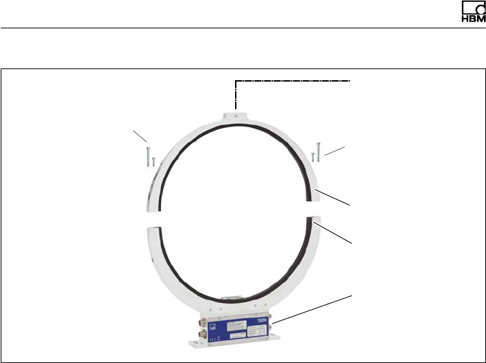
Mechanical installation
28 A4429-1.0 HBM: public T40FH
Ø 6.5 mm hole for fixing
the antenna segment
Stator housing
upper
Antenna segment
screws with washers
(M4+M5)
lower
Antenna segments
Antenna segment
screws with washers
(M4+M5)
Fig. 5.6 Bolted connection of the antenna segments on the
stator
1. Undo and remove both the bolted connections
(M4+M5) on the upper antenna segment.
There are fan-type lock washers (M4+M5) between
the antenna segments: make sure that they do not get
lost.
2. Use an appropriate mounting base to install the stator
housing in the shaft train, so that there is sufficient
opportunity for horizontal and vertical adjustments. Do
not fully tighten the screws yet.
3. Now use four hexagon socket screws to mount the
upper antenna segment removed in Point 1 on the
lower antenna segment.

Mechanical installation
T40FH A4429-1.0 HBM: public 29
Make sure that the fan-type lock washers are inserted
between the antenna segments (these ensure that
there is a defined contact resistance)!
Important
To guarantee that they function perfectly, the fan-type
lock washers (A5, 3-FST DIN 6798 ZN/galvanized) must
be replaced after the bolted antenna connection has
been loosened three times.
4. Now tighten all the bolted antenna segment connec
tions with a tightening torque of 5 N⋅m.
5. Then align the antenna to the rotor in such a way that
the antenna encloses the rotor more or less coaxially
and the antenna wire in the axial direction has the
same position as the center of the transmitter winding
on the rotor.
To make alignment easier, the outer edge of the stator
antenna segment and the outer edge of the stator
winding carrier should be on the same line (in align
ment). Conform to the permissible alignment toler
ances stated in the specifications.
6. Now fully tighten the bolted stator housing connection.
Prevention of axial stator oscillation
Depending on the operating conditions, stator oscillation
may be induced. This effect is dependent on:
Sthe rotational speed,
Sthe antenna diameter (depends in turn on the measur
ing range),
Sthe construction of the machine base.
Mechanical installation
30 A4429-1.0 HBM: public T40FH
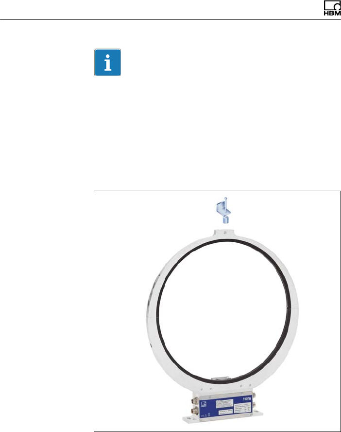
Important
To avoid axial oscillation, a clamp fixture is enclosed with
the torque transducer to enable the antenna ring to be
supported. There is a hole, 6.5 mm in diameter, on the
upper antenna segment to receive the clamping device
(see Fig. 5.7).
The cable plug (not included in the scope of supply) also
requires support in this case; a construction example is
shown in Fig. 5.9.
Fig. 5.7 Construction example for supporting the antenna
ring
Mechanical installation
T40FH A4429-1.0 HBM: public 31
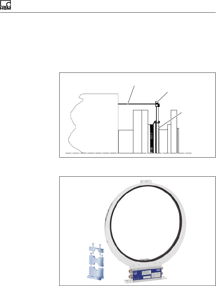
7. Fasten the clamp fixture with the enclosed bolted con
nection, as shown in Fig. 5.8. Clamp a suitable sup
port element (we recommend a Ø 3-6 mm threaded
rod) between the upper and lower parts of the clamp
fixture and tighten the clamping screws.
Support supplied by customer
Clamp fixture
Antenna ring
Fig. 5.8 Supporting the antenna ring
Fig. 5.9 Construction example for plug clamps (for two
plugs)

Mechanical installation
32 A4429-1.0 HBM: public T40FH
5.8 Rotational speed measuring system
The rotor is delivered as standard with a ring gear for the
rotational speed measuring system. The option is avail
able to fit the stator with a sensor head to scan the
mechanical increments (ring gear).
Sensor head for
measuring rotational
speed (optional)
Ring gear
Fig. 5.10 Torque transducer with rotational speed
measurement (optional)
Important
The rotational speed measuring system uses a magnetic
measuring principle. In applications where high magnetic
field strengths can occur, e.g. eddy-current brakes, imple
ment suitable measures to ensure that the maximum per
missible magnetic field strength cannot be exceeded (see
Chapter 15 "Specifications", Page 64).

Mechanical installation
T40FH A4429-1.0 HBM: public 33
Stator alignment (rotational speed measuring
system)
For measuring mode to operate perfectly, the speed sen
sor must be placed at a defined position to the rotor ring
gear. When the radial and axial alignment of the stator is
accurate for torque measurement, the alignment of the
rotational speed measuring system is also correct.
Axial alignment:
At the factory, the sensor head of the rotational speed
measuring system must be adjusted so that when the
axial alignment of the stator is exact (antenna ring posi
tioned precisely above the rotor winding carrier), the sen
sor is in the correct position to the rotor ring gear.
Mechanical installation
34 A4429-1.0 HBM: public T40FH
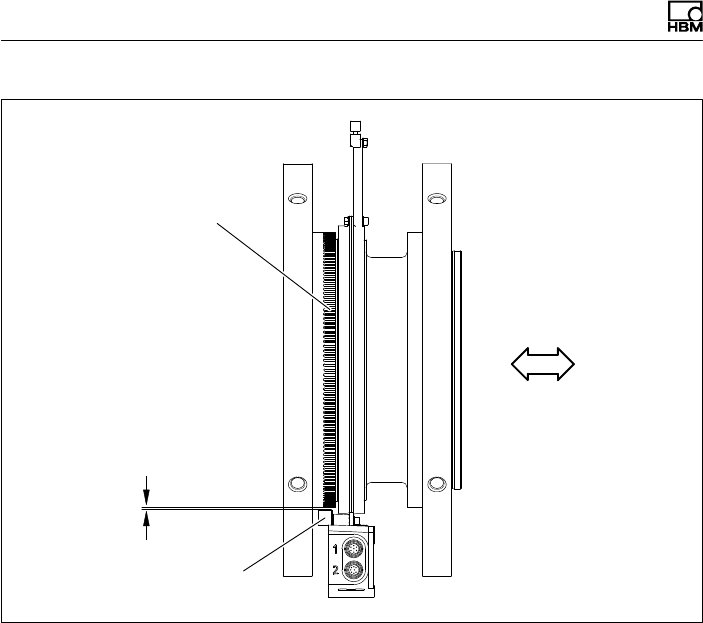
Ring gear
Speed sensor
Radial
distance
Axial alignment
Fig. 5.11 Side view
Radial alignment:
The rotor axis and the axis of the speed sensor must be
along a line at right angles to the stator platform. The
nominal radial distance is crucial for radial alignment (see
Fig. 5.11). The optimum distance is 2.5 mm and is
achieved when the rotor and the stator are in precise
radial alignment.
Electrical connection
T40FH A4429-1.0 HBM: public 35
6 Electrical connection
6.1 General information
SWith extension cables, make sure that there is a
proper connection with minimum contact resistance
and good insulation.
SAll plug connections or swivel nuts must be fully tight
ened.
Important
Transducer connection cables from HBM with attached
connectors are marked in accordance with their intended
purpose (Md or n). When cables are shortened, inserted
into cable ducts or installed in control cabinets, this mark
ing can be lost or hidden. So the cables must be marked
beforehand, just in case.
6.2 EMC protection
Important
Transducers are EMC-tested in accordance with EC
directives and identified by CE certification. However, you
must connect the shield of the connection cable on the
shielding electronics enclosure in order to achieve EMC
protection for the measuring chain.

Electrical connection
36 A4429-1.0 HBM: public T40FH
Special electronic coding methods are used to protect the
purely digital signal transmission between the transmitter
head and the rotor from electromagnetic interference.
The cable shield is connected with the transducer hous
ing. This encloses the measurement system (without the
rotor) in a Faraday cage when the shield is laid flat at
both ends of the cable. With other connection techniques,
an EMC-proof shield should be applied in the wire area
and this shielding should also be laid flat (also see HBM
Greenline Information, brochure i1577).
Electrical and magnetic fields often induce interference
voltages in the measuring circuit. Therefore:
SUse shielded, low-capacitance measurement cables
only (HBM cables fulfill both conditions).
SOnly use plugs that meet EMC guidelines.
SDo not route the measurement cables parallel to
power lines and control circuits. If this is not possible,
protect the measurement cable witha steel conduit,
for example.
SAvoid stray fields from transformers, motors and con
tact switches.
SDo not ground the transducer, amplifier and indicator
more than once.
SConnect all the devices in the measuring chain to the
same protective conductor.
SIn the case of interference due to potential differences
(compensating currents), supply voltage zero and
housing ground must be disconnected on the amplifier
and a potential equalization line established between
the stator housing and the amplifier housing (copper
conductor, minimum 10 mm2 wire crosssection).

Electrical connection
T40FH A4429-1.0 HBM: public 37
SShould differences in potential occur between the
machine rotor and stator because of unchecked leak
age, for example, this can usually be overcome by
connecting the rotor definitively to ground, e.g. with a
wire loop. The stator must be connected to the same
(ground) potential.
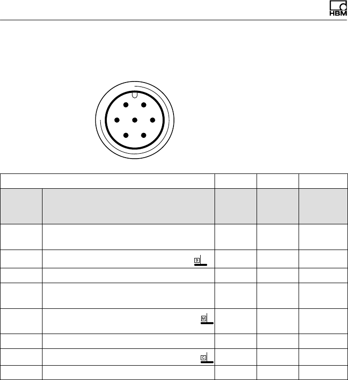
6.3 Connector pin assignment Option 4,
Code SU2, DU2, HU2
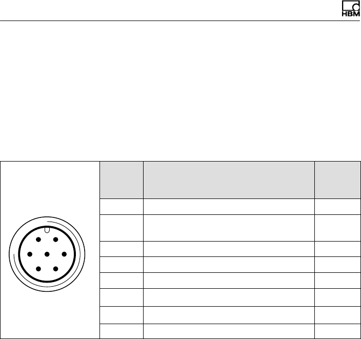
The stator housing has two 7-pin connectors, an 8-pin
connector and a 16-pin connector.
The supply voltage and shunt signal connections of con
nectors 1 and 3 are each electrically interconnected, but
are protected against compensating currents by diodes.
There is also a self-resetting fuse (multifuse) to protect
the supply voltage connections against overload by the
stator.
Electrical connection
38 A4429-1.0 HBM: public T40FH
Assignment for connector 1 - supply voltage and
frequency output signal
61
572
43
Device plug
Top view
KAB153 KAB149 KAB1781)
Con
nector
pin
Assignment Color
code
D‐SUB
connec
tor pin
HD‐SUB
connector
pin
1Torque measurement signal
(frequency output; 5 V2,3)wh 13 5
2Supply voltage 0 V bk 5 -
3Supply voltage 18 V …30 V bu 6 -
4Torque measurement signal
(frequency output; 5 V2,3)rd 12 10
5Measurement signal 0 V; symmet
rical gy 8 6
6Shunt signal trigger 5 V … 30 V gn 14 15
7Shunt signal 0 V gy 8
Shield connected to housing ground
1) Bridge between 4 + 9
2) RS-422 complementary signals; with cable lengths exceeding 10 m, we recommend using a
termination resistor R = 120 ohms between the (wh) and (rd) wires.
3) RS‐422: Pin 1 corresponds to A, Pin 4 corresponds to B.
Electrical connection
T40FH A4429-1.0 HBM: public 39
Notice
Torque flanges are only intended for operation with a DC
supply voltage. They must not be connected to older
HBM amplifiers with square-wave excitation. This could
destroy the connection board resistors or cause other
faults in the amplifiers.
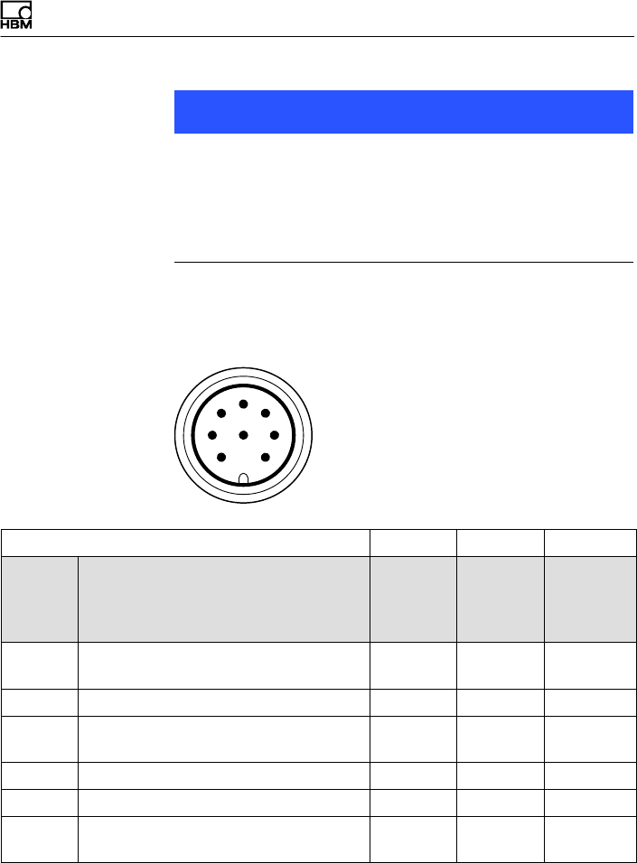
Assignment for connector 2 - rotational speed
measuring system
6
1
5
7
2
4
38
Device plug
Top view
KAB154 KAB150 KAB1791)
Con
nector
pin
Assignment Color
code
D-SUB
connec
tor
pin
HD-SUB
connec
tor
pin
1Speed measurement signal 2) (pulse
string, 5V; 0°)rd 12 10
2Not in use bu - -
3Speed measurement signal 2 (pulse
string, 5 V; 90° phase shifted) gy 15 8
4Not in use bk - -
5Not in use vt - -
6Speed measurement signal 2)
(pulse string, 5V; 0°)wh 13 5
Electrical connection
40 A4429-1.0 HBM: public T40FH
HD-SUB
connec
tor
pin
D-SUB
connec
tor
pin
Color
code
AssignmentCon
nector
pin
7Speed measurement signal 2(pulse
string, 5 V; 90° phase shifted) gn 14 7
8Supply voltage zero bk/bu 3) 8 6
Shield connected to housing ground
1) Bridge between 4 + 9
2) RS-422 complementary signals; with cable lengths exceeding 10 m, we recommend using a
termination resistor of R = 120 ohms.
3) For KAB163 / KAB164 color code brown (bn)
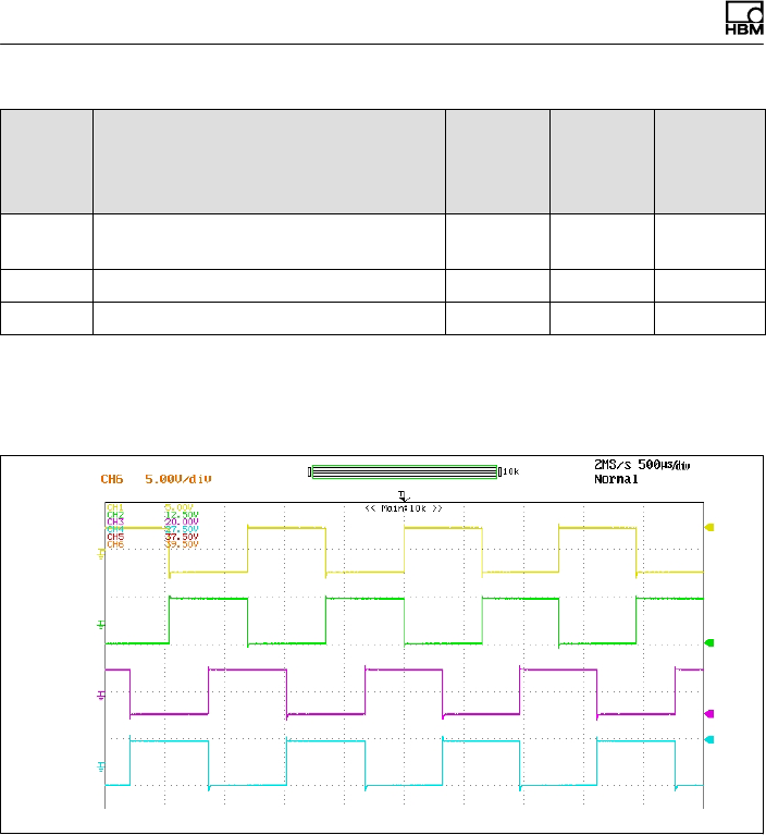
Pin 1
Pin 6
Pin 3
Pin 7
Fig. 6.1 Speed signals at connector 2 (rotational speed in
the direction of the arrow)
Electrical connection
T40FH A4429-1.0 HBM: public 41
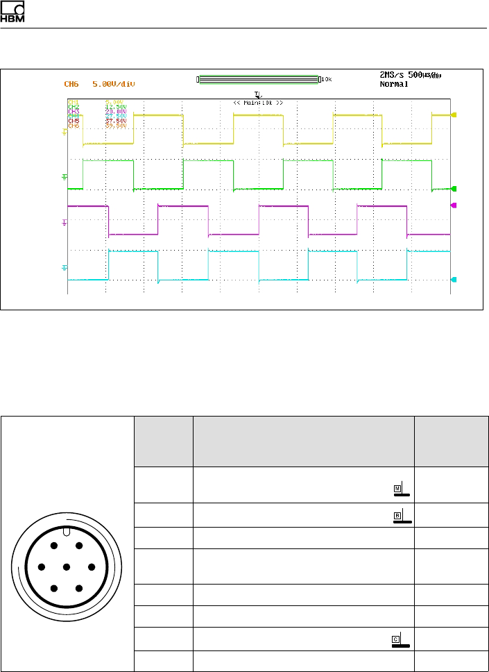
Pin 1
Pin 6
Pin 3
Pin 7
Fig. 6.2 Speed signals at connector 2 (rotational speed
against the direction of the arrow)
Assignment for connector 3 - supply voltage and
frequency output signal
61
572
43
Device plug
Top view
Con
nector
pin
Assignment Color
code
1Torque measurement signal
(voltage output; ±10 V) wh
2Supply voltage 0 V; bk
3Supply voltage 18 V …30 V bu
4Torque measurement signal (voltage
output; ±10 V) rd
5Not in use gy
6Shunt signal trigger 5 V … 30 V gn
7Shunt signal 0 V; gy
Shield connected to housing ground
Electrical connection
42 A4429-1.0 HBM: public T40FH
Assignment for connector 4
TMC - only for connection to the Torque Interface Mod
ules of the TIM family within HBM.
6.4 Connector pin assignment Option 3,
Code PNJ
61
572
43
Binder 723
Top view
Con
nector
pin
Assignment Color
code
1Measurement signal (+) UAwh
2Bridge excitation voltage (-) UB and
TEDS
bk
3Bridge excitation voltage (+) UBbu
4Measurement signal (-) UArd
5Not in use -
6Sense lead (+) gn
7Sense lead (-) and TEDS gy
Shield connected to housing ground
6.5 Supply voltage (SU2, DU2, HU2)
The transducer must be operated with a safety extra-low
voltage (nominal (rated) supply voltage 18 … 30 VDC).
You can supply one or more torque flanges within a test
bench. Should the device be operated on a DC voltage
network1), additional precautions must be taken to dis
charge excess voltages.
1) Distribution system for electrical energy with greater physical expansion (over several test
benches, for example) that may possibly also supply consumers with high nominal (rated)
currents.
Electrical connection
T40FH A4429-1.0 HBM: public 43
The information in this Chapter relates to the standalone
operation of the T40FH without HBM system solutions.
The supply voltage is electrically isolated from the signal
outputs and shunt signal inputs. Connect a safety extra-
low voltage of 18 V … 30 V to pin 3 (+) and pin 2 ( ) of
connectors 1 or 3. We recommend that you use HBM
cable KAB 8/00 -2/2/2 and appropriate sockets (see
accessories, Page 62). The cable can be up to 50 m long
for voltages ≥24 V, otherwise it can be up to 20 m long.
If the permissible cable length is exceeded, you can feed
the supply voltage in parallel over two connection cables
(connectors 1 and 3). This enables you to double the per
missible length. Alternatively, install an on-site power
supply.
Important
The instant you switch on, a current of up to 4 A may
flow and this can switch off power packs with electronic
current limiters.
6.6 Supply voltage (Option 3, Code PNJ)
A pre-wired 6-wire transducer connection cable with free
ends is available as an accessory.
Extension cables should be shielded and low capaci
tance. HBM provides specific cables for this purpose, the
1-KAB0304A-10 (pre-wired) and the KAB8/00-2/2/2 (by
the meter).
The pin assignment can be found in the table in section
6.4.
For the pin assignments at the amplifier end, please refer
to the relevant amplifier documentation.

Electrical connection
44 A4429-1.0 HBM: public T40FH
7 TEDS transducer identification
(Option 3, Code PNJ)
TEDS stands for "Transducer Electronic Data Sheet". An
electronic data sheet can be stored in the transducer as
defined in the IEEE1451.4 standard, making it possible
for the amplifier to be set up automatically. A suitably
equipped amplifier reads out the transducer characteris
tics (electronic data sheet), translates them into its own
settings and measurement can then start.
The digital identification system is available at plug con
nection PIN 7 to PIN 2. The HBM TEDS Editor is used to
store the data. This is a component of the HBM
"MGCplus Setup Assistant" software. You can use the
Editor to manage different user rights, thus protecting the
essential transducer data from being overwritten by mis
take.
7.1 Hierarchy of user rights
7.1.1 Standard rights (USR level)
This level concerns rights which the user of the trans
ducer needs in order to change the entries which depend
on the conditions of use.
7.1.2 Calibration rights (CAL level)
This level concerns rights which are needed by a calibra
tion laboratory, for instance, if the sensitivity in the TEDS
memory needs to be changed.

Electrical connection
T40FH A4429-1.0 HBM: public 45
7.1.3 Administrator rights (ID level)
Administrator rights in relation to TEDS are intended for
the sensor manufacturer.
Different user rights are needed in order to amend the
various entries in the templates, and these rights may
differ from one entry to the next within a template.
7.2 Contents of the TEDS memory as
defined in IEEE 1451.4
The information in the TEDS memory is organized into
areas, which are prestructured to store defined groups of
data in table form.
Only the entered values are stored in the TEDS memory
itself. The amplifier firmware assigns the interpretation of
the respective numerical values. This places a very low
demand on the TEDS memory. The memory content is
divided into three areas:
Area 1
An internationally unique TEDS identification number
(cannot be changed).
Area 2
The base area (basic TEDS), to the configuration defined
in standard IEEE 1451.4. The transducer type, the manu
facturer and the transducer serial number are contained
here.

Electrical connection
46 A4429-1.0 HBM: public T40FH
Example:
TEDS content with the identity number for the T40FH/150
kN@m sensor with serial no. 123456, made in November
2005
TEDS transducer identification
Manufacturer HBM
Model T40FH
Version letter
Version number
Serial number 123456
Area 3
Data specified by the manufacturer and the user are con
tained in this area.
For the T40FH torque flange, HBM has already described
the Bridge Sensor and Channel name templates.
Additional templates, such as the Signal Conditioning
template, can also be described by the user.
Template: Bridge Sensor
Parameter Value1)Unit Required
user
rights
Explanation
Transducer Elec
trical Signal Type
Bridge
Sensor
ID
Minimum Torque 0.000 N@m CAL The physical measurand
and unit are defined
when the template is cre
ated, after which they
cannot be changed.
Maximum Torque 150000 N@m CAL

Electrical connection
T40FH A4429-1.0 HBM: public 47
Template: Bridge Sensor
ExplanationRequired
user
rights
UnitValue1)
Parameter
Minimum Electri
cal
Value
0.0000m V/V CAL The difference between
these values is the sensi
tivity according to the
HBM manufacturing cer
tificate or from the cali
bration.
Maximum Electri
cal Value
1.8245m V/V CAL
Mapping Method Linear This entry cannot be
changed
Bridge type Full ID The bridge type. "Full" for
a full bridge.
Impedance of
each bridge ele
ment
1550+-100 ohm ID Input resistance accord
ing to the HBM data
sheet
Response time 1.0000000u s ID Of no significance to
HBM transducers
Excitation Level
(Nominal)
5.0 V ID Nominal (rated) excita
tion voltage according to
the HBM data sheet
Excitation Level
(Minimum)
2.5 V ID Lower limit for the oper
ating range of the excita
tion voltage according to
the HBM data sheet.
Excitation Level
(Maximum)
12.0 V ID Upper limit for the oper
ating range of the excita
tion voltage according to
the HBM data sheet.

Electrical connection
48 A4429-1.0 HBM: public T40FH
Template: Bridge Sensor
ExplanationRequired
user
rights
UnitValue1)
Parameter
Calibration Date 1-Nov-2005 CAL Date of the last calibra
tion or creation of the test
certificate (if no calibra
tion carried out), or of the
storage of the TEDS data
(if only nominal (rated)
values from the data
sheet were used).
Format: day-month-year.
Abbreviations for the
months: Jan, Feb, Mar,
Apr, May, Jun, Jul, Aug,
Sep, Oct, Nov, Dec.
Calibration Initials HBM CAL Initials of the calibrator or
calibration laboratory
concerned.
Calibration Period
(Days)
730 days CAL Time before recalibra
tion, calculated from the
date specified under Cal
ibration Date.
Measurement
location ID
0 USR Identification number for
the measuring point.
Can be assigned accord
ing to the application.
Possible values: a num
ber from 0 to 2047. If this
is not enough, the HBM
Channel Comment tem
plate can also be used
for this purpose.
1) Typical values for an HBM T40FH/150 kN@m torque flange

Electrical connection
T40FH A4429-1.0 HBM: public 49
Template: HBM Channel Name
Channel name T40FH/150 kNm
When creating the Bridge Sensor template, the manufac
turer defines the physical measured quantity and the
physical unit.
The available unit for the particular measured quantity is
specified in the IEEE Standard. For the measured quan
tity of torque, the unit is "N@m".
At the time of creating the template it is also necessary to
choose between the options "Full Precision", "mV/V" and
"uV/V" for the accuracy of the characteristic transducer
curve mapped in TEDS.
The factory setting is "Full Precision", in order to be able
to use full digital resolution. This choice is also recom
mended to users who program the TEDS memory them
selves.
Shunt signal
50 A4429-1.0 HBM: public T40FH
8 Shunt signal
The T40FH torque flange delivers an electrical shunt sig
nal that can be activated from the amplifier for measuring
chains with HBM components. The transducer generates
a shunt signal of about 50% of the nominal (rated)
torque; the precise value is specified on the type plate.
After activation, adjust the amplifier output signal to the
shunt signal supplied by the connected transducer, to
adapt the amplifier to the transducer.
Information
The transducer should not be under load when the shunt
signal is being measured, as the shunt signal is mixed
additively.
Triggering the shunt signal
Applying a safety extra-low voltage of 5 … 30 V to pins 6
(+) and 7 ( ) at connector 1 or 3, triggers the shunt sig
nal.
The nominal (rated) voltage for triggering the shunt signal
is 5V (triggering at U > 2.5V), but when voltages are less
than 0.7V, the transducer is in measuring mode. The
maximum permissible voltage is 30V, current consump
tion at nominal (rated) voltage is approx. 2 mA and at
maximum voltage, approx. 18 mA. The trigger voltage for
the shunt signal is electrically isolated from the supply
voltage and the measuring voltage.
Tip
The shunt signal can be triggered by the amplifier or via
the operating software in HBM system solutions.
Functionality testing
T40FH A4429-1.0 HBM: public 51
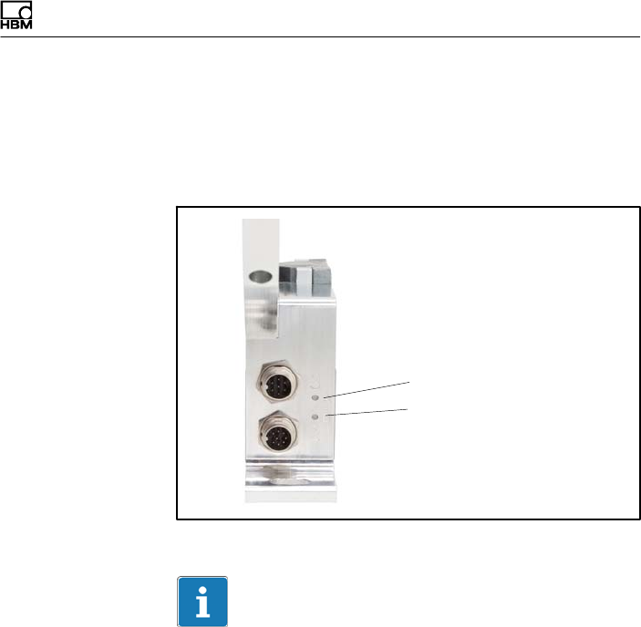
9 Functionality testing
You can check the functionality of the rotor and the stator
from the LEDs on the stator.
LED A, rotor status
LED B, stator status
Fig. 9.1 LEDs on the stator housing
Important
Once the supply voltage is applied, the torque transducer
needs up to a further 4 seconds to be ready for operation.

Functionality testing
52 A4429-1.0 HBM: public T40FH
9.1 Rotor status, LED A (upper LED)
Color Significance
Green (pulsating) Internal rotor voltage values o.k.
Flashing orange Rotor and stator mismatched (an increasing flashing fre
quency indicates the degree of misalignment)
=> Correct the rotor/stator alignment.
Pulsating orange Rotor status cannot be defined
=> Correct the rotor/stator alignment.
If the LED still pulsates orange, it is possible that there is a
hardware defect. The measurement signals reflect the level of
the fault.
Red (pulsating) Rotor voltage values not o.k.
=> Correct the rotor/stator alignment.
If the LED still pulsates red, it is possible that there is a hard
ware defect. The measurement signals reflect the level of the
fault.
Pulsating means that the LED goes dark for about 20 ms
every second (sign of life), making it possible to detect
that the transducer is functioning.
9.2 Stator status, LED B (lower LED)
Color Significance
Green
(permanently lit)
Measurement signal transmission and internal stator voltages
o.k.
Green, intermittently
orange.
Numerous synchro
nization errors:
permanently orange
Orange if y5 measured values in succession are transmitted
incorrectly, until the end of incorrect transmission. The mea
surement signals reflect the level of the fault for the duration
of the transmission error + for approx. another 3.3 ms.

Functionality testing
T40FH A4429-1.0 HBM: public 53
SignificanceColor
Orange
(permanently lit)
Permanently disrupted transmission, the measurement sig
nals reflect the level of the fault. (fout = 0 Hz, Uout = defect
level).
=> Correct the rotor/stator alignment.
Red
(permanently lit)
Internal stator defect, the measurement signals reflect the
level of the fault (fout = 0 Hz, Uout = defect level).

Load-carrying capacity
54 A4429-1.0 HBM: public T40FH
10 Load-carrying capacity
Nominal (rated) torque can be exceeded statically up to
the torque limit. If the nominal torque is exceeded, addi
tional irregular loading is not permissible. This includes
longitudinal forces, lateral forces and bending moments.
Limit values can be found in Chapter "" on Page 64.
Measuring dynamic torque
The torque flange can be used to measure static and
dynamic torques. The following apply to the measure
ment of dynamic torque:
SThe T40FH calibration performed for static measure
ments is also valid for dynamic torque measurements.
SThe natural frequency f0 of the mechanical measuring
arrangement depends on the moments of inertia J1
and J2 of the connected rotating masses and the tor
sional stiffness of the T40FH.
Use the equation below to approximately determine the
natural frequency f0 of the mechanical measuring
arrangement:
f0+1
2p· cT·ǒ1
J1
)1
J2Ǔ
Ǹf0= natural frequency in Hz
J1, J2= mass moment of inertia in kg⋅m2
cT= torsional stiffness in N⋅m/rad
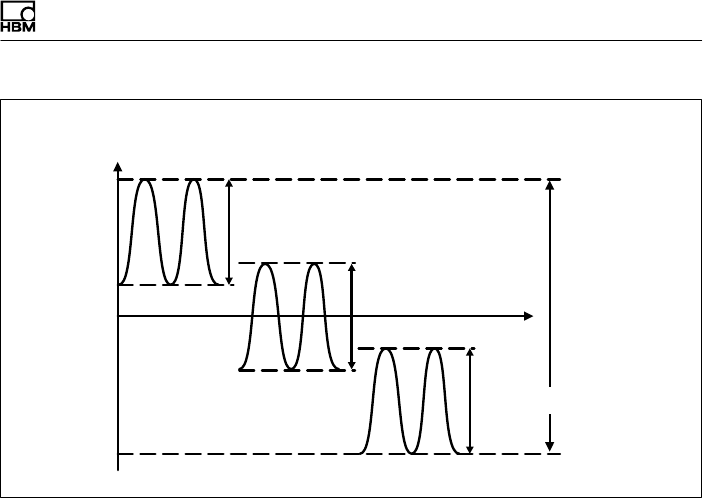
SThe permissible mechanical vibration bandwidth
(peak-to-peak) can also be found in the specifications.
Load-carrying capacity
T40FH A4429-1.0 HBM: public 55
0
+ Mnom
200% oscillation
bandwidth
- Mnom
Nominal (rated) torque Mnom as
a %
Time t
Oscillation bandwidth
Oscillation bandwidth
Oscillation bandwidth
Fig. 10.1 Permissible dynamic loading

Maintenance
56 A4429-1.0 HBM: public T40FH
11 Maintenance
T40FH torque flanges are maintenance free.

Waste disposal and environmental protection
T40FH A4429-1.0 HBM: public 57
12 Waste disposal and environmental protection
All electrical and electronic products must be disposed of
as hazardous waste. The correct disposal of old equip
ment prevents ecological damage and health hazards.
Statutory waste disposal mark
The electrical and electronic devices that bear this sym
bol are subject to the European waste electrical and elec
tronic equipment directive 2002/96/EC. The symbol indi
cates that, in accordance with national and local
environmental protection and material recovery and recy
cling regulations, old devices that can no longer be used
must be disposed of separately and not with normal
household garbage.
As waste disposal regulations may differ from country to
country, we ask that you contact your supplier to deter
mine what type of disposal or recycling is legally applica
ble in your country.
Packaging
The original packaging of HBM devices is made from
recyclable material and can be sent for recycling. Store
the packaging for at least the duration of the warranty. In
the case of complaints, the torque flange must be
returned in the original packaging.
For ecological reasons, empty packaging should not be
returned to us.
Dimensions
58 A4429-1.0 HBM: public T40FH
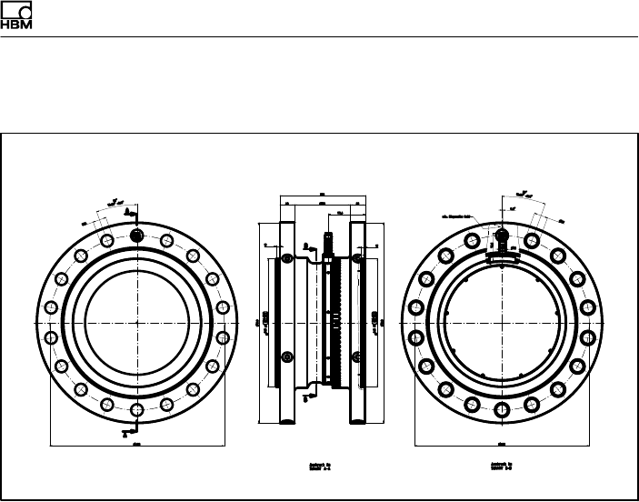
13 Dimensions
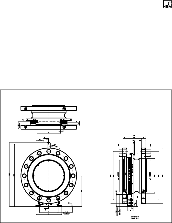
13.1 T40FH torque transducer with
rotational speed measuring system,
Option 4, Code SU2, DU2, HU2
13.1.1 T40FH 100kNm - 150kNm
Dimensions in mm (1 mm = 0.03937 inches)
Dimensions
T40FH A4429-1.0 HBM: public 59
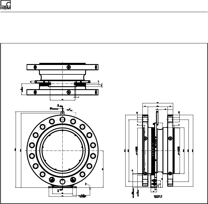
13.1.2 T40FH 200kNm - 300kNm
Dimensions in mm (1 mm = 0.03937 inches)
Dimensions
60 A4429-1.0 HBM: public T40FH
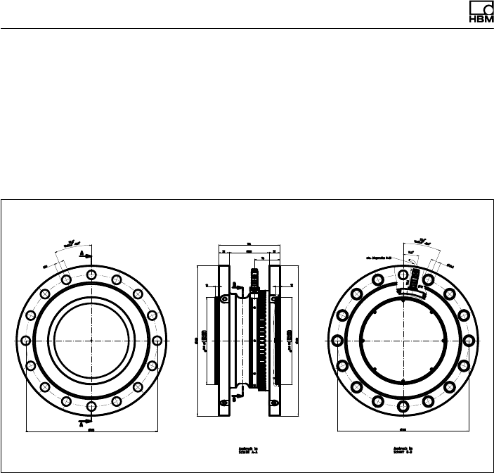
13.2 T40FH torque transducer
(non-rotating),
Option 4, Code PNJ
13.2.1 T40FH 100 kNm - 150 kNm
Dimensions in mm (1 mm = 0.03937 inches)
Dimensions
T40FH A4429-1.0 HBM: public 61
13.2.2 T40FH 200kNm - 300kNm
Dimensions in mm (1 mm = 0.03937 inches)
= PREFERRED TYPES
Ordering numbers, accessories
62 A4429-1.0 HBM: public T40FH
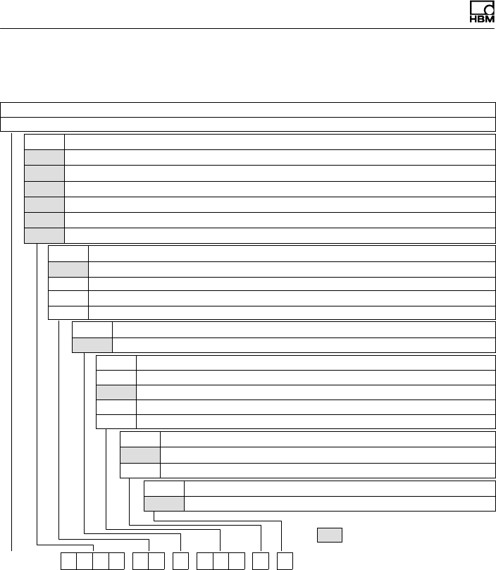
14 Ordering numbers, accessories
Ordering number
K-T40FH [only with Option 2 = MF/ST]
Code Option 1: Measuring range to
100R 100 kN·m [only with Option 2 = MF/RO]
130R 130 kN·m [only with Option 2 = MF/RO]
150R 150 kN·m [only with Option 2 = MF/RO]
200R 200 kN·m [only with Option 2 = MF/RO]
250R 250 kN·m [only with Option 2 = MF/RO]
300R 300 kN·m [only with Option 2 = MF/RO]
Code Option 2: Components
MF Complete measurement flange
RO Rotor
ST Stator
NNot rotating
Code Option 3: Accuracy
SStandard (linearity deviation including hysteresis ≤±0.1%)
Code Option 4: Electrical configuration [only with Option 2 = MF/ST]
SU2 Out. sign. 10 kHz ±5 kHz and ±10 V, Supp. volt. 18…30V DC
DU2 Out. sign. 60 kHz ±30 kHz and ±10 V, Supp. volt. 18…30V DC
HU2 Out. sign. 240 kHz ±120 kHz and ±10 V, Supp. volt. 18…30V DC
PNJ mV/V
Code Option 5: Rotational speed measuring system
0Without rotational speed measuring system
1Magnetic rotational speed measuring system
Code Option 6: Customized modification
SNo customer modification
K-T40FH - 1 0 0 R - M F - S - D U 2 - 0 - S
Ordering numbers, accessories
T40FH A4429-1.0 HBM: public 63
Accessories, to be ordered separately
Article Ordering
number
Connection cable for torque output
Torque connection cable, 423 - D‐Sub 15P, 6m 1-KAB149-6
Torque connection cable, 423 - free ends, 6m 1-KAB153-6
Connection cable for rotational speed output
Rotational speed connection cable, 423 - D-Sub 15P, 6m 1-KAB150-6
Rotational speed connection cable, 423 - free ends, 6m 1-KAB154-6
Rotational speed with reference signal connection cable, 423 8-pin -
D-Sub 15P, 6m
1-KAB163-6
Rotational speed with reference signal connection cable, 423 8-pin -
free ends, 6m
1-KAB164-6
TMC connection cable
TIM40/TMC connection cable, 6m 1-KAB174-6
Cable sockets
423G-7S, 7-pin (straight) 3-3101.0247
423W-7S, 7-pin (angle) 3-3312.0281
423G-8S, 8-pin (straight) 3-3312.0120
423W-8S, 8-pin (angle) 3-3312.0282
Connection cable, by the meter (min. order quantity: 10 m, price per meter)
Kab8/00-2/2/2 4-3301.0071

Specifications
64 A4429-1.0 HBM: public T40FH
15 Specifications
Accuracy class 0.1
Torque measuring system (rotating)
Nominal (rated) torque Mnom kNm 100 125 150 200 250 300
Nominal (rated) rotational speed rpm 3000 2000
Linearity deviation including
hysteresis,
related to nominal (rated) sensitivity
Frequency output
For a max. torque in the range:
between 0% of Mnom and 20% of
Mnom
% ≤±0.03
> 20% of Mnom and 60% of Mnom % ≤±0.065
> 60% of Mnom and 100% of Mnom % ≤±0.1
Voltage output
For a max. torque in the range:
between 0% of Mnom and 20% of
Mnom
% ≤±0.03
> 20% of Mnom and 60% of Mnom % ≤±0.065
> 60% of Mnom and 100% of Mnom % ≤±0.1
Rel. standard deviation of repeata
bility,
per DIN1319, related to the variation
of the output signal
Frequency output % ≤±0.02
Voltage output % ≤±0.02
Temperature effect per 10 K in the
nominal (rated) temperature range
on the output signal, related to the
actual value of the signal span
Frequency output % ≤±0.1

Specifications
T40FH A4429-1.0 HBM: public 65
Nominal (rated) torque Mnom 300250200150125100kNm
Voltage output % ≤±0.1
on the zero signal, related to nominal
(rated) sensitivity
Frequency output % ≤±0.07
Voltage output % ≤±0.07
Nominal (rated) sensitivity
(spread between torque = zero and
nominal (rated) torque)
Frequency output 10kHz / 60kHz /
240kHz
kHz 5/30/120
Voltage output V 10
Sensitivity tolerance
(deviation of the actual output quantity
at Mnom from the nominal (rated) sen
sitivity)
Frequency output % ±0.1
Voltage output % ±0.1
Output signal at torque = zero
Frequency output kHz 10/60/240
Voltage output V 0
Nominal (rated) output signal
Frequency output
at positive nominal (rated) torque kHz 15 1) / 90 2) / 360 3)
(5 V balanced 4))
at negative nominal (rated) torque kHz 5 1) / 30 2) / 120 3)
(5 V balanced 4))
Voltage output
at positive nominal (rated) torque V +10
at negative nominal (rated) torque V -10

Specifications
66 A4429-1.0 HBM: public T40FH
Nominal (rated) torque Mnom 300250200150125100kNm
Load resistance
Frequency output kΩ≥2
Voltage output kΩ≥10
Longterm drift over 48h at refer
ence temperature
Frequency output % ≤±0.03
Voltage output % ≤±0.03
Measurement frequency range,
-3 dB
kHz 11) / 32) / 63)
Group delay μst4001) / t2202) / t1503)
Residual ripple
Voltage output 5) mV t40
Maximum modulation range 6)
Frequency output kHz 2.5 … 17.5 1) / 15 … 105 2) /
60 … 420 3)
Voltage output V-12 … +12
Energy supply
Nominal (rated) supply voltage (DC
safety extra low voltage)
V18 … 30
Current consumption in measuring
mode
A< 1
Current consumption in startup mode A< 4 (typically 2) 50 μs
Nominal (rated) power consumption W< 10
Maximum cable length m 50
Shunt signal approx. 50 % of Mnom
Tolerance of the shunt signal,
related to Mnom
% <±0.05
Nominal (rated) trigger voltage V 5
Trigger voltage limit V 36
Shunt signal ON Vmin. >2.5

Specifications
T40FH A4429-1.0 HBM: public 67
Nominal (rated) torque Mnom 300250200150125100kNm
Shunt signal OFF Vmax. <0.7
Torque measuring system (non-rotating)
Accuracy class 0.1
Nominal (rated) sensitivity (nominal
(rated) signal range between torque =
zero and nominal (rated) torque)
mV/V 0.63…..1.1 (the sensitivity is
specified on the type plate)
Linearity deviation including hys
teresis, related to the nominal
(rated) sensitivity (voltage output)
For a max. torque in range:
between 0% of Mnom and 20% of
Mnom
%≤± 0.03
> 20% of Mnom and 60% of Mnom %≤± 0.065
> 60% of Mnom and 100% of Mnom %≤± 0.1
Temperature effect per 10 K in the
nominal (rated) temperature range
on the output signal, related to the
actual value of the signal span
%≤± 0.1
on the zero signal, related to nominal
(rated) sensitivity
%≤± 0.07
Relative standard deviation of
reproducibility (variability) per DIN
1319, related to the variation of the
output signal.
%≤± 0.02
Input resistance at reference
temperature
Ω1560 ± 100
Output resistance at reference
temperature
Ω1400 ± 100
Reference excitation voltage V 5
Operating range of the excitation voltage 2.5 ... 12
Transducer identification TEDS as per IEEE 1451.4

Specifications
68 A4429-1.0 HBM: public T40FH
Nominal (rated) torque Mnom 300250200150125100kNm
Rotational speed measuring system
Rotational speed measuring system Magnetic scanning and ring gear
Output signals 2 square wave signals 90° phase
shifted, 5V TTL/RS-422
Number of pulses per revolution
(number of teeth)
72 86
Output signal level High V ≥3.5
Output signal level Low V ≤0.8
Maximum permissible output fre
quency
kHz 25
Radial nominal distance between
sensor head and teeth
mm 2.5
Radial working range mm 1.5 – 3.5
Permissible axial displacement mm ±2
Permissible magnetic field strength
for signal deviations
kA/m <0.1
General information
EMC
Emission (as per FCC 47, Part 15,
Subsection C) 7)
Emission
(as per EN61326‐1, Section 7)
RFI field strength Class B
Immunity to interference (EN
61326-1, Table 2)
Electromagnetic field (AM) V/m 10
Magnetic field A/m 100
Electrostatic discharge (ESD)
Contact discharge kV 4
Air discharge kV 8
Fast transients (burst) kV 1

Specifications
T40FH A4429-1.0 HBM: public 69
Nominal (rated) torque Mnom 300250200150125100kNm
Impulse voltages (surge) kV 1
Conducted interference (AM) V 10
Degree of protection per EN60529 IP 54
Reference temperature °C23
Nominal temperature range °C+10 … +70
Operating temperature range 8) °C-20 … +85
Storage temperature range °C-40 … +85
Mechanical shock per
EN60068‐2‐279)
Number n 1000
Duration ms 3
Acceleration (half sine) m/s2650
Vibrational stress in three direc
tions per EN60068-2-6 9)
Frequency range Hz 10 … 2000
Duration h 2.5
Acceleration (amplitude) m/s2100
Load limits 10)
Torque limit, related to Mnom11) kNm 200 400
Breaking torque, related to Mnom11) kNm >300 >600
Axial limit force 12) kN 230 290
Lateral limit force 12) kN 110 240
Bending moment limit 12) N⋅m 22 35
Oscillation width per DIN 50100
(peaktopeak) 13) kNm 200 400
Upper maximum torque kNm 150 300
Lower maximum torque kNm -150 -300

Specifications
70 A4429-1.0 HBM: public T40FH
Nominal (rated) torque Mnom 300250200150125100kNm
Mechanical values
Size BG1 BG2
Torsional stiffness cTkN⋅m/rad 119310 228090
Torsion angle at Mnom degrees 0.072 0.075
Stiffness in the axial direction cakN/mm 1855 3900
Stiffness in the radial direction crkN/mm 3340 4910
Stiffness during the bending
moment round a radial axis cb
kN⋅m/rad 25495 65900
kN⋅m/
degrees
445 1150
Maximum deflection at axial limit
force
mm <0.1
Additional maximum radial devia
tion at lateral limit force
mm <0.1
Additional maximum deviation from
plane parallelism at bending
moment limit
mm <0.5
Balance quality level per
DIN ISO 1940
G 6.3
Max. limits for relative shaft vibra
tion14) (peak-to-peak)
Undulations in the connection flange
area, based on ISO7919‐3
Normal operation (continuous
operation)
μm s(p*p)+9000
n
Ǹ(n in rpm)
Start and stop operation/reso
nance ranges (temporary)
μm s(p*p)+13200
n
Ǹ(n in rpm)
Mass moment of inertia of rotor Jv
(around the rotary axis; does not take
flange bolts into account)
kg⋅m22.0 5.15
Proportional mass moment of iner
tia for the transmitter side (side of
the flange with external centering)
% of Iv45 47

Specifications
T40FH A4429-1.0 HBM: public 71
Nominal (rated) torque Mnom 300250200150125100kNm
Max. permissible static eccentricity
of the rotor (radially) to the center
point of the stator
without the speed module mm ±2
with rotational speed module mm ±1
Permissible axial displacement15)
between rotor and stator
mm ±2
Weight
Rotor kg 78 142
Stator kg 2.1 2.3
1) Option 5, 10 ±5 kHz (code SU2)
2) Option 5, 60 ±30 kHz (code DU2)
3) Option 5, 240 ±120 kHz (code HU2)
4) RS-422 complementary signals, note line termination.
5) Signal frequency range 0.1 to 10kHz
6) Output signal range in which there is a repeatable correlation between torque and output signal.
7) Only for rotating version
8) Heat conductance via the stator base plate necessary over 70°C. The temperature of the base
plate must not exceed 85°C.
9) The antenna ring and connector plug must be fixed.
10) Each type of irregular stress (bending moment, lateral or longitudinal force, exceeding nominal
(rated) torque), can only be permitted up to its specified load limit, provided none of the others
can occur at the same time. If this condition is not met, the limit values must be reduced. If 30%
of the bending moment limit and the lateral limit force occur at the same time, only 40% of the
axial limit force is permissible and the nominal (rated) torque must not be exceeded. The effects
of permissible bending moments, axial and lateral forces on the measurement result are v±1%
of the nominal (rated) torque. The load limits only apply for the nominal (rated) temperature
range. At temperatures <10°C, the load limits must be reduced by approx. 30% (strength
reduction).
11) With static load.
12) Static and dynamic.
13) The nominal (rated) torque must not be exceeded.
14) The influence of radial run-out deviations, eccentricity, defects of form, notches, marks, local
residual magnetism, structural inhomogeneity or material anomalies needs to be taken into
account and isolated from the actual undulation.
15) Above the nominal (rated) temperature range: ±1.5mm.
Supplementary technical information
72 A4429-1.0 HBM: public T40FH
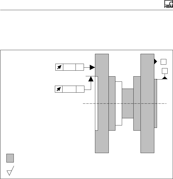
16 Supplementary technical information
Axial and radial run-out tolerances
Internal centering
A
002 AB
B
002 AB
Flange A Flange B
Hardness 46 ... 54
HRC
Surface quality of the axial and radial run-out tolerances (A, B and AB)
0.8
To ensure that the torque flange retains its characteristics
once it is installed, we recommend that the customer also
chooses the specified form and position tolerances, sur
face quality and hardness for the connections provided.
Mounting Instructions | Montageanleitung
English Deutsch
T40FH

2A4429-1.0 HBM: public T40FH
Deutsch
1 Sicherheitshinweise 4......................................
2 Verwendete Kennzeichnungen 12.............................
2.1 Auf dem Aufnehmer angebrachte Symbole 12....................
2.2 In dieser Anleitung verwendete Kennzeichnungen 13..............
3 Anwendung 14..............................................
4 Aufbau und Wirkungsweise 15...............................
5 Mechanischer Einbau 17.....................................
5.1 Wichtige Vorkehrungen beim Einbau 17.........................
5.2 Bedingungen am Einbauort 18..................................
5.3 Einbaulage 19................................................
5.4 Einbaumöglichkeiten 20.......................................
5.4.1 Einbau mit demontiertem Antennenring 21.......................
5.5 Rotormontage vorbereiten 22...................................
5.6 Montage des Rotors 26........................................
5.7 Montage des Stators 29.......................................
5.8 Drehzahlmesssystem 35.......................................
6 Elektrischer Anschluss 38....................................
6.1 Allgemeine Hinweise 38.......................................
6.2 EMV‐Schutz 38...............................................
6.3 Steckerbelegung Option 4, Code SU2, DU2, HU2 40..............
6.4 Steckerbelegung Option 3, Code PNJ 45.........................
6.5 Versorgungsspannung (SU2, DU2, HU2) 45......................
6.6 Versorgungsspannung (Option 3, Code PNJ) 46..................
7 Aufnehmer‐Identifikation TEDS (Option 3, Code PNJ) 47.......
7.1 Hierarchie der Nutzerrechte 47.................................
7.1.1 Standardrechte (Stufe USR) 47.................................
7.1.2 Kalibrierrechte (Stufe CAL) 48..................................

T40FH A4429-1.0 HBM: public 3
7.1.3 Administratorrechte (Stufe ID) 48...............................
7.2 Inhalt des TEDS‐Speicher nach IEEE 1451.4 48..................
8 Shuntsignal 54..............................................
9 Funktionsprüfung 56........................................
9.1 Rotorstatus, LED A (obere LED) 57.............................
9.2 Statorstatus, LED B (untere LED) 57............................
10 Belastbarkeit 59.............................................
11 Wartung 61..................................................
12 Entsorgung und Umweltschutz 62............................
13 Abmessungen 63............................................
13.1 T40FH Drehmomentaufnehmer mit Drehzahlmesssystem,
Option 4, Code SU2, DU2, HU2 63..............................
13.1.1 T40FH 100kNm - 150kNm 63.................................
13.1.2 T40FH 200kNm - 300kNm 64.................................
13.2 T40FH Drehmomentaufnehmer (nicht drehend),
Option 4, Code PNJ 65........................................
13.2.1 T40FH 100 kNm - 150 kNm 65.................................
13.2.2 T40FH 200kNm - 300kNm 66.................................
14 Bestellnummern, Zubehör 67.................................
15 Technische Daten 69.........................................
16 Ergänzende technische Informationen 77.....................
Sicherheitshinweise
4A4429-1.0 HBM: public T40FH
1 Sicherheitshinweise
FCC-Konformität und Hinweis
Information
FCC-Option ausschließlich auf Anfrage verfügbar.
Wichtig
Durch Änderungen, die nicht ausdrücklich schriftlich von
der für die Konformität zuständigen Person genehmigt
wurden, könnte die Berechtigung zum Betrieb des Geräts
verfallen. Sofern angegeben, müssen zusätzliche
Komponenten oder Zubehörteile, deren Verwendung bei
der Installation des Produkts an anderer Stelle vorgege
ben ist, verwendet werden, um die Einhaltung der FCC-
Vorschriften zu gewährleisten.
Dieses Gerät entspricht Teil 15 der FCC-Vorschriften.
Der Betrieb unterliegt den beiden nachstehenden
Bedingungen: (1) Dieses Gerät darf keine schädlichen
Störungen verursachen und (2) dieses Gerät muss Stö
rungen akzeptieren können, auch solche, die ein
unerwünschtes Betriebsverhalten zur Folge haben
können.
Die FCC-Kennung bzw. die eindeutige Kennung muss
am Gerät sichtbar sein.
Modell Messbereiche FCC ID IC
T40S10 100 kNm, 130 kNm,
150 kNm 2ADAT−T40S10TOS11 12438A−T40S10TOS11
T40S11 200 kNm, 250 kNm,
300 kNm

Sicherheitshinweise
T40FH A4429-1.0 HBM: public 5
Beispiel eines Labels mit FCC-ID und IC-Nummer.
Schild
Abb. 1.1 Position des Labels am Stator des Geräts
Model: T40S10
FCC ID: 2ADAT-T40S10TOS11
IC: 12438AT40S10TOS11
This device complies with part 15 of the FCC Rules. Operation is
subject to the following two conditions: (1) This device may not
cause harmful interference, and (2) this device must accept any
interference received, including interference that may cause
undesired operation.
Abb. 1.2 Beispiel eines Labels

Sicherheitshinweise
6A4429-1.0 HBM: public T40FH
Dieses Gerät entspricht der Industry-Canada-Norm
RSS210.
Dieses Gerät entspricht der bzw. den RSS-Normen von
Industry Canada für nicht genehmigungspflichtige
Geräte. Der Betrieb unterliegt den beiden nachstehenden
Bedingungen: (1) Dieses Gerät darf keine Störungen ver
ursachen und (2) dieses Gerät muss Störungen akzep
tieren können, auch solche, die ein unerwünschtes
Betriebsverhalten des Geräts zur Folge haben können.
This device complies with Industry Canada standard
RSS210.
This device complies with Industry Canada
license‐exempt RSS standard(s).Operation is subject to
the following two conditions: (1) this device may not
cause interference, and (2) this device must accept any
interference, including interference that may cause unde
sired operation of the device.
Cet appareil est conforme aux norme RSS210 d’Industrie
Canada.
Cet appareil est conforme aux normes d’exemption de
licence RSS d’Industry Canada. Son fonctionnement est
soumis aux deux conditions suivantes : (1)cet appareil ne
doit pas causer d’interférence et (2) cet appareil doit
accepter toute interférence, notamment les interférences
qui peuvent affecter son fonctionnement.
Bestimmungsgemäße Verwendung
Der Drehmoment‐Messflansch T40FH ist für Dreh
moment‐, Drehwinkel‐ und Leistungs‐Messaufgaben im
Rahmen der durch die technischen Daten spezifizierten
Belastungsgrenzen konzipiert. Jeder andere Gebrauch ist
nicht bestimmungsgemäß.

Sicherheitshinweise
T40FH A4429-1.0 HBM: public 7
Der Betrieb des Stators ist nur mit montiertem Rotor
zulässig.
Der Drehmoment‐Messflansch darf nur von qualifiziertem
Personal ausschließlich entsprechend der technischen
Daten unter Beachtung der Sicherheitsbestimmungen
und Vorschriften dieser Montageanleitung eingesetzt
werden. Zusätzlich sind die für den jeweiligen
Anwendungsfall geltenden Rechts‐ und Sicherheitsvor
schriften zu beachten. Sinngemäß gilt dies auch bei der
Verwendung von Zubehör.
Der Drehmoment‐Messflansch ist nicht zum Einsatz als
Sicherheitsbauteil bestimmt. Bitte beachten Sie hierzu
den Abschnitt „Zusätzliche Sicherheitsvorkehrungen“.
Der einwandfreie und sichere Betrieb setzt sachgemäßen
Transport, fachgerechte Lagerung, Aufstellung und
Montage sowie sorgfältige Bedienung voraus.
Belastbarkeitsgrenzen
Beim Einsatz des Drehmoment‐Messflanschs sind die
Angaben in den technischen Datenblättern unbedingt zu
beachten. Insbesondere dürfen die jeweils angegebenen
Maximalbelastungen keinesfalls überschritten werden.
Nicht überschritten werden dürfen z.B. die in den
technischen Daten angegebenen Werte für
SGrenzdrehmoment,
SGrenzlängskraft, Grenzquerkraft oder Grenz
biegemoment,
SSchwingbreite des Drehmoments,
SBruchdrehmoment,
STemperaturgrenzen,
Sdie Grenzen der elektrischen Belastbarkeit.

Sicherheitshinweise
8A4429-1.0 HBM: public T40FH
Einsatz als Maschinenelemente
Der Drehmoment‐Messflansch kann als Maschinen
elemente eingesetzt werden. Bei dieser Verwendung ist
zu beachten, dass der Aufnehmer zu Gunsten einer
hohen Messempfindlichkeit nicht mit den im
Maschinenbau üblichen Sicherheitsfaktoren konstruiert
wurde. Beachten Sie hierzu den Abschnitt „Belast
barkeitsgrenzen“ und die technischen Daten.
Unfallverhütung
Entsprechend den einschlägigen Unfallverhütungsvor
schriften der Berufsgenossenschaften ist nach der Mon
tage des Aufnehmers vom Betreiber eine Abdeckung
oder Verkleidung wie folgt anzubringen:
SAbdeckung oder Verkleidung dürfen nicht mitrotieren.
SAbdeckung oder Verkleidung sollen sowohl Quetsch‐
und Scherstellen vermeiden als auch vor evtl. sich
lösenden Teilen schützen.
SAbdeckungen und Verkleidungen müssen weit genug
von den bewegten Teilen entfernt oder so beschaffen
sein, dass man nicht hindurchgreifen kann.
SAbdeckungen und Verkleidungen müssen auch ange
bracht sein, wenn die bewegten Teile des Dreh
moment‐Messflanschs außerhalb des Verkehrs‐ und
Arbeitsbereiches von Personen installiert sind.
Von den vorstehenden Forderungen darf nur abgewichen
werden, wenn der Drehmoment‐Messflansch schon
durch den Aufbau der Maschine oder bereits vorhandene
Schutzvorkehrungen ausreichend gesichert ist.
Zusätzliche Sicherheitsvorkehrungen
Der Drehmoment‐Messflansch kann (als passiver
Aufnehmer) keine (sicherheitsrelevanten) Abschaltungen

Sicherheitshinweise
T40FH A4429-1.0 HBM: public 9
vornehmen. Dafür bedarf es weiterer Komponenten und
konstruktiver Vorkehrungen, für die der Errichter und
Betreiber der Anlage Sorge zu tragen hat. Die das Mess
signal verarbeitende Elektronik ist so zu gestalten, dass
bei Ausfall des Messsignals keine Folgeschäden
auftreten können.
Der Leistungs‐ und Lieferumfang des Aufnehmers deckt
nur einen Teilbereich der Drehmoment‐Messtechnik ab.
Sicherheitstechnische Belange sind vom Anlagenplaner/
Ausrüster/Betreiber so zu planen, zu realisieren und zu
verantworten, dass Restgefahren minimiert werden. Die
jeweils existierenden nationalen und örtlichen
Vorschriften sind zu beachten.
Allgemeine Gefahren bei Nichtbeachten der
Sicherheitshinweise
Der Drehmoment‐Messflansch entspricht dem Stand der
Technik und ist betriebssicher. Von dem Aufnehmer
können Gefahren ausgehen, wenn er von ungeschultem
Personal oder unsachgemäß montiert, aufgestellt, einge
setzt und bedient wird. Jede Person, die mit Aufstellung,
Inbetriebnahme, Betrieb oder Reparatur eines Dreh
moment‐Messflanschs beauftragt ist, muss die
Montageanleitung und insbesondere die sicherheits
technischen Hinweise gelesen und verstanden haben.
Bei nicht bestimmungsgemäßem Gebrauch des Aufneh
mers, bei Nichtbeachtung der Montage‐ und Bedienungs
anleitung, dieser Sicherheitshinweise oder sonstiger
einschlägiger Sicherheitsvorschriften (Unfallverhütungs
vorschriften der BG) beim Umgang mit dem Aufnehmer,
kann der Aufnehmer beschädigt oder zerstört werden.
Insbesondere bei Überlastungen kann es zum Bruch des
Aufnehmers kommen. Durch den Bruch können darüber
hinaus Sachen oder Personen in der Umgebung des Auf
nehmers zu Schaden kommen.

Sicherheitshinweise
10 A4429-1.0 HBM: public T40FH
Wird der Drehmoment‐Messflansch nicht seiner Bestim
mung gemäß eingesetzt oder werden die Sicherheitshin
weise oder die Vorgaben der Montage‐ oder Bedienungs
anleitung außer Acht gelassen, kann es ferner zum
Ausfall oder zu Fehlfunktionen des Aufnehmers kommen,
mit der Folge, dass (durch auf den Drehmoment‐Mess
flansch einwirkende oder durch diesen überwachte Dreh
momente) Menschen oder Sachen zu Schaden kommen
können.
Umbauten und Veränderungen
Der Aufnehmer darf ohne unsere ausdrückliche Zustim
mung weder konstruktiv noch sicherheitstechnisch
verändert werden. Jede Veränderung schließt eine Haf
tung unsererseits für daraus resultierende Schäden aus.
Veräußerung
Bei einer Veräußerung des Drehmoment‐Messflanschs
ist diese Montageanleitung dem Drehmoment‐Mess
flansch beizulegen.
Qualifiziertes Personal
Qualifiziertes Personal sind Personen, die mit Aufstel
lung, Montage, Inbetriebsetzung und Betrieb des Pro
duktes vertraut sind und die über die ihrer Tätigkeit ent
sprechende Qualifikationen verfügen.
Dazu zählen Personen, die mindestens eine der drei
folgenden Voraussetzungen erfüllen:
1. Ihnen sind die Sicherheitskonzepte der Automa
tisierungstechnik bekannt und Sie sind als Projektper
sonal damit vertraut.
2. Sie sind Bedienungspersonal der Automatisierungs
anlagen und im Umgang mit den Anlagen
unterwiesen. Sie sind mit der Bedienung der in dieser

Sicherheitshinweise
T40FH A4429-1.0 HBM: public 11
Dokumentation beschriebenen Geräte und Technolo
gien vertraut.
3. Sie sind Inbetriebnehmer oder für den Service einge
setzt und haben eine Ausbildung absolviert, die Sie
zur Reparatur der Automatisierungsanlagen befähigt.
Außerdem haben Sie eine Berechtigung, Stromkreise
und Geräte gemäß den Normen der Sicherheits
technik in Betrieb zu nehmen, zu erden und zu kenn
zeichnen.
Verwendete Kennzeichnungen
12 A4429-1.0 HBM: public T40FH
2 Verwendete Kennzeichnungen
2.1 Auf dem Aufnehmer angebrachte
Symbole
Angaben in dieser Anleitung nachlesen und
berücksichtigen
CE‐Kennzeichnung
Mit der CE‐Kennzeichnung garantiert der Hersteller, dass
sein Produkt den Anforderungen der relevanten EG‐
Richtlinien entspricht (die Konformitätserklärung finden
Sie auf der Website von HBM www.hbm.com unter HBM
doc).
Beispiel eines Labels
Beispiel eines Labels mit FCC-ID und IC-Nummer.
Position des Labels am Stator des Geräts.
Gesetzlich vorgeschriebene Kennzeichnung zur
Entsorgung
Elektrische und elektronische Geräte, die dieses Symbol
tragen, unterliegen der europäischen Richtlinie
2002/96/EG über elektrische und elektronische Altgeräte.
Das Symbol weist darauf hin, dass nicht mehr ge
brauchsfähige Altgeräte gemäß den europäischen Vor
schriften für Umweltschutz und Rohstoffrückgewinnung
getrennt von regulärem Hausmüll zu entsorgen sind,
siehe auch Kapitel 12, Seite 62.
Model: T40S10
FCC ID: 2ADAT-T40S10TOS11
IC: 12438AT40S10TOS11
This device complies with part 15 of the
FCC Rules. Operation is subject to the fol
lowing two conditions: (1) This device may
not cause harmful interference, and (2)
this device must accept any interference
received, including interference that may
cause undesired operation.
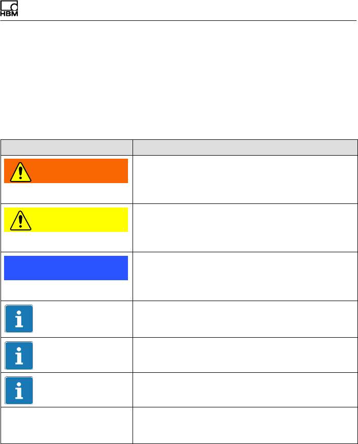
Verwendete Kennzeichnungen
T40FH A4429-1.0 HBM: public 13
2.2 In dieser Anleitung verwendete
Kennzeichnungen
Wichtige Hinweise für Ihre Sicherheit sind besonders ge
kennzeichnet. Beachten Sie diese Hinweise unbedingt,
um Unfälle und Sachschäden zu vermeiden.
Symbol Bedeutung
WARNUNG Diese Kennzeichnung weist auf eine mögliche
gefährliche Situation hin, die – wenn die Sicherheits
bestimmungen nicht beachtet werden – Tod oder
schwere Körperverletzung zur Folge haben kann.
VORSICHT Diese Kennzeichnung weist auf eine mögliche
gefährliche Situation hin, die – wenn die Sicherheits
bestimmungen nicht beachtet werden – leichte oder
mittlere Körperverletzung zur Folge haben kann.
Hinweis Diese Kennzeichnung weist auf eine Situation hin,
die – wenn die Sicherheitsbestimmungen nicht
beachtet werden – Sachschäden zur Folge haben
kann.
Wichtig
Diese Kennzeichnung weist auf wichtige Informa
tionen zum Produkt oder zur Handhabung des Pro
duktes hin.
Tipp
Diese Kennzeichnung weist auf Anwendungstipps
oder andere für Sie nützliche Informationen hin.
Information
Diese Kennzeichnung weist auf Informationen zum
Produkt oder zur Handhabung des Produktes hin.
Hervorhebung
Siehe …
Kursive Schrift kennzeichnet Hervorhebungen im
Text und kennzeichnet Verweise auf Kapitel, Bilder
oder externe Dokumente und Dateien.

Anwendung
14 A4429-1.0 HBM: public T40FH
3 Anwendung
Der Drehmoment‐Messflansch T40FH erfasst statische
und dynamische Drehmomente an ruhenden oder rotie
renden Wellen. Der Aufnehmer ermöglicht durch seine
kurze Bauweise äußerst kompakte Prüfaufbauten.
Dadurch ergeben sich vielfältige Anwendungen.
Der Drehmomentflansch T40FH verfügt über einen
zuverlässigen Schutz vor elektromagnetischen Stö
rungen. Er wurde gemäß harmonisierten europäischen
Normen getestet und/oder entspricht US-amerikanischen
und kanadischen Normen. Am Produkt befindet sich das
CE-Kennzeichen und/oder das FCC-Label.

Aufbau und Wirkungsweise
T40FH A4429-1.0 HBM: public 15
4 Aufbau und Wirkungsweise
Der Drehmoment‐Messflansch besteht aus zwei getrenn
ten Teilen, dem Rotor und dem Stator. Der Rotor setzt
sich zusammen aus dem Messkörper und den Signal‐
Übertragungselementen.
Auf dem Messkörper sind Dehnungsmessstreifen (DMS)
installiert. Die Rotorelektronik für die Brückenspeisespan
nungs‐ und Messsignalübertragung ist zentrisch im
Flansch angeordnet. Der Messkörper trägt am äußeren
Umfang die Übertragerspulen für die berührungslose
Übertragung von Speisespannung und Messsignal. Die
Signale werden von einem teilbaren Antennenring gesen
det bzw. empfangen. Der Antennenring ist auf einem Ge
häuse befestigt, in dem die Elektronik für die Spannungs
anpassung sowie die Signalaufbereitung untergebracht
sind.
Am Stator befinden sich Anschlussstecker für das Dreh
moment‐ und das Drehzahlsignal, die Spannungsversor
gung und den digitalen Ausgang. Die Antennensegmente
(der Antennenring) müssen konzentrisch um den Rotor
montiert werden (siehe Kapitel 5).
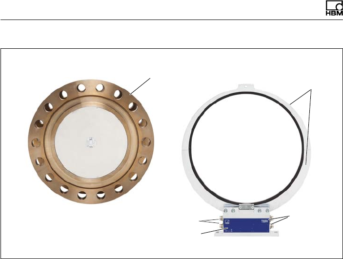
Aufbau und Wirkungsweise
16 A4429-1.0 HBM: public T40FH
Antennen
segmente
Rotor
Anschluss
stecker
Statorgehäuse
Typenschild
Anschlussstecker
Abb. 4.1 Mechanischer Aufbau
Bei der Option 5 mit Drehzahlmesssystem ist auf dem
Stator der Drehzahlsensor montiert. Die Drehzahl
messung erfolgt magnetisch mittels Feldplattensensor
und einem am Rotor angebrachten Zahnkranz.

Mechanischer Einbau
T40FH A4429-1.0 HBM: public 17
5 Mechanischer Einbau
5.1 Wichtige Vorkehrungen beim Einbau
Hinweis
Ein Drehmoment‐Messflansch ist ein Präzisions‐Mess
element und verlangt daher eine umsichtige Hand
habung. Stöße oder Stürze können zu permanenten
Schäden am Aufnehmer führen. Sorgen Sie dafür, dass
auch bei der Montage keine Überlastung des Aufneh
mers auftreten kann.
SBehandeln Sie den Aufnehmer schonend.
SPrüfen Sie den Einfluss von Biegemomenten, kri
tischen Drehzahlen und Torsionseigenschwingungen,
um eine Überlastung des Aufnehmers durch Reso
nanzüberhöhungen zu vermeiden.
SStellen Sie sicher, dass der Aufnehmer nicht
überlastet werden kann.
WARNUNG
Bei einer Überlastung des Aufnehmers besteht die
Gefahr, dass der Aufnehmer bricht. Dadurch können
Gefahren für das Bedienpersonal der Anlage auftreten, in
die der Aufnehmer eingebaut ist.
Treffen Sie geeignete Sicherungsmaßnahmen zur
Vermeidung einer Überlastung und zur Sicherung gegen
sich daraus ergebende Gefahren.
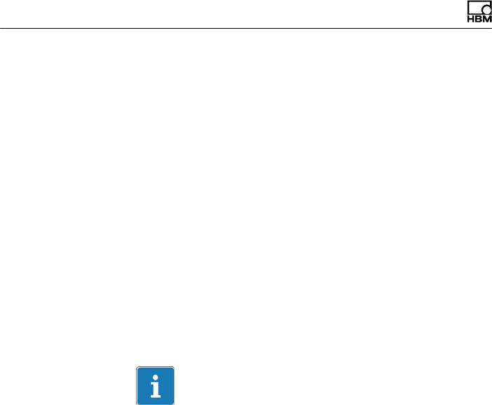
Mechanischer Einbau
18 A4429-1.0 HBM: public T40FH
SKleben Sie die Verbindungsschrauben mit einer
Schraubensicherung (mittelfest, z.B. von LOCTITE) in
das Gegengewinde ein, um einen Vorspannverlust
durch Lockern auszuschließen, falls Wechsellasten zu
erwarten sind.
SHalten Sie die Montagemaße unbedingt ein, um einen
einwandfreien Betrieb zu ermöglichen.
Der Drehmoment‐Messflansch T40FH kann über einen
entsprechenden Wellenflansch direkt montiert werden.
Am Rotor ist auch die direkte Montage einer Gelenkwelle
oder entsprechender Ausgleichselemente (bei Bedarf
über Zwischenflansch) möglich. Die zulässigen Grenzen
für Biegemomente, Quer‐ und Längskräfte dürfen jedoch
in keinem Fall überschritten werden. Durch die hohe
Drehsteifigkeit des Aufnehmers T40FH werden dynami
sche Veränderungen des Wellenstrangs gering gehalten.
Wichtig
Auch bei korrektem Einbau kann sich der im Werk ab
geglichene Nullpunkt bis zu ca. 0,5% vom Kennwert ver
schieben. Wird dieser Wert überschritten, empfehlen wir,
die Einbausituation zu prüfen. Ist der bleibende Null
punktversatz im ausgebauten Zustand größer als 1%
vom Kennwert, senden Sie den Aufnehmer bitte zur Prü
fung ins Werk Darmstadt.
5.2 Bedingungen am Einbauort
Der Drehmoment‐Messflansch T40FH muss vor grobem
Schmutz, Staub, Öl, Lösungsmitteln und Feuchtigkeit
geschützt werden.

Mechanischer Einbau
T40FH A4429-1.0 HBM: public 19
Der Aufnehmer ist in weiten Grenzen gegen Temperatu
reinflüsse auf das Ausgangs‐ und Nullsignal kompensiert
(siehe Kapitel 15 „Technische Daten“). Liegen keine sta
tionären Temperaturverhältnisse vor, z.B. durch Tempe
raturunterschiede zwischen Messkörper und Flansch,
können die in den technischen Daten spezifizierten Werte
überschritten werden. Sorgen Sie in diesen Fällen je
nach Anwendungsfall durch Kühlung oder Heizung für
stationäre Temperaturverhältnisse. Prüfen Sie alternativ,
ob eine Temperaturentkopplung möglich ist, z.B. durch
Wärme abstrahlende Elemente wie Lamellenkupplungen.
5.3 Einbaulage
Die Einbaulage des Drehmoment‐Messflanschs ist belie
big.
Bei Rechtsdrehmoment (im Uhrzeigersinn) beträgt die
Ausgangsfrequenz bei Option 5, Code DU2 60 … 90 kHz
(Option 5, Code SU2: 10 … 15kHz; Option HU2: 240 …
360kHz). In Verbindung mit Messverstärkern von HBM
oder bei Nutzung des Spannungsausgangs steht ein po
sitives Ausgangssignal (0 V …+10 V) an. Beim Dreh
zahl‐Messsystem ist zum eindeutigen Bestimmen der
Drehrichtung auf dem Statorgehäuse ein Pfeil ange
bracht: Dreht der Messflansch in Pfeilrichtung, liefern
angeschlossene HBM‐Messverstärker ein positives Aus
gangssignal.
Bei der nichtdrehenden Ausführung ist bei Rechtsdreh
moment das Ausgangssignal in mV/V positiv.

Mechanischer Einbau
20 A4429-1.0 HBM: public T40FH
5.4 Einbaumöglichkeiten
Da der Durchmesser kleiner ist als der Flanschducr
hmesser des Rototrs, muss der Antennenring beid er
Montage zerlegt werden. Bei schlechten Zugangsmög
lichkeiten zum Rotor im eingebauten Zustand, empfehlen
wir, den Antennenring bereits vorher zu zerlegen. Beach
ten Sie hierbei unbedingt die Hinweise zum Zusamm
menbau der Antennensegmente (siehe Kapitel 5.7).
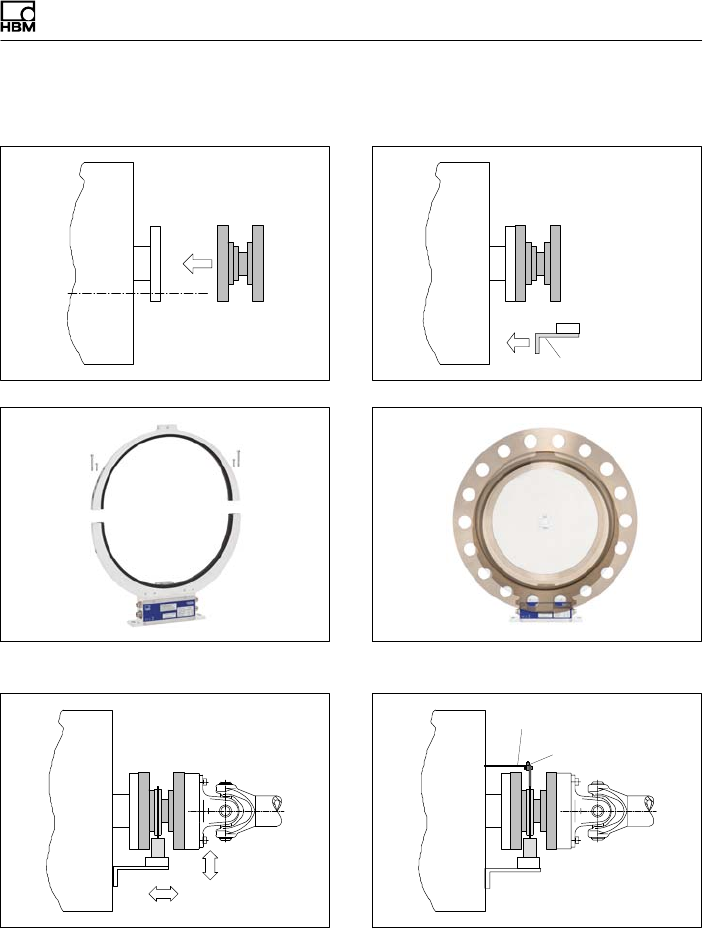
Mechanischer Einbau
T40FH A4429-1.0 HBM: public 21
5.4.1 Einbau mit demontiertem Antennenring
Kundenseitige
Befestigung
1. Rotor installieren
3. Ein Antennensegment demontieren
5. Stator ausrichten und fertig montieren
2. Statorbefestigung montieren
4. Antennensegment um den Wellenstrang
montieren
6. Klemmstück montieren
Kundenseitige Abstützung
Klemmstück
Mechanischer Einbau
22 A4429-1.0 HBM: public T40FH
5.5 Rotormontage vorbereiten
VORSICHT
Der Rotor ist schwer (je nach Messbereich bis zu
142 kg)! Verwenden Sie zum Heben aus der Verpackung
und zur Montage einen Kran oder andere geeignete He
bevorrichtungen.
Beachten Sie beim Arbeiten mit dem Kran die entspre
chenden Sicherheitsvorschriften und tragen Sie Sicher
heitsschuhe.
1. Entfernen Sie die obere Schaumstofflage der Verpak
kung.
Abb. 5.1 Verpackung des T40FH
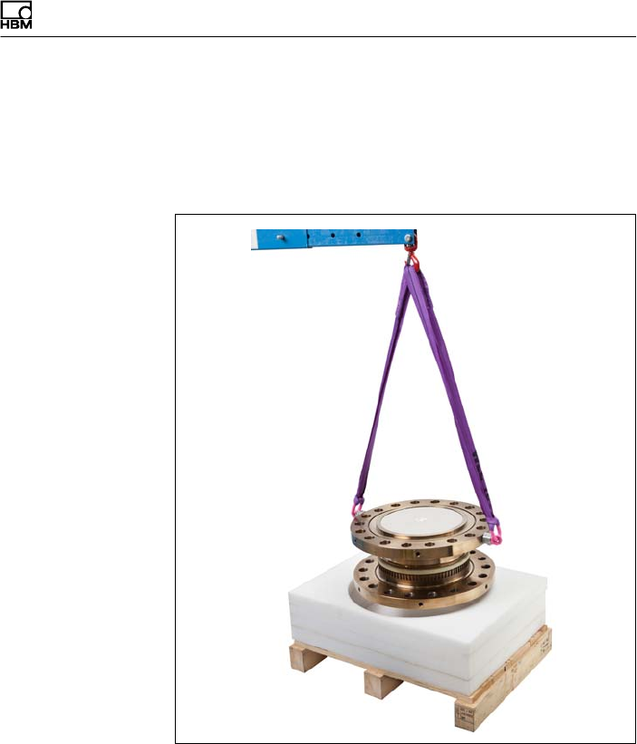
Mechanischer Einbau
T40FH A4429-1.0 HBM: public 23
2. Befestigen Sie an den Hebeösen zwei gleich lange
Seile mit ausreichender Tragfähigkeit (jedes der zwei
Seile muss das volle Rotorgewicht tragen können)
und heben Sie den Rotor mit einem Kran aus der Ver
packung (siehe Abb. 5.2).
Abb. 5.2 Rotor aus der Verpackung heben
3. Stellen Sie den Rotor auf einer sauberen, stabilen
Unterlage ab.
4. Entfernen Sie eine Hebeöse.
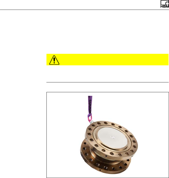
Mechanischer Einbau
24 A4429-1.0 HBM: public T40FH
5. Heben Sie den Rotor vorsichtig an, bis er frei hängt.
6. Kippen Sie den Rotor vorsichtig beim Ablassen über
die Flanschkante, bis er auf beiden Flanschaußenflä
chen waagerecht steht (siehe Abb. 5.3).
VORSICHT
Quetschgefahr. Halten Sie mit Händen und Füßen genü
gend Abstand zum Rotor.
Abb. 5.3 Rotor kippen
7. Sichern Sie den Rotor mit Keilen gegen Wegrollen.
8. Schrauben Sie die zweite Hebeöse wieder in die Ge
windebohrungen in der Flanschaußenfläche ein.
9. Befestigen Sie den Rotor mit zwei gleich langen Sei
len am Kranhaken. Der Rotor ist nun für einen hori
zontalen Einbau vorbereitet (siehe Abb. 5.4).

Mechanischer Einbau
T40FH A4429-1.0 HBM: public 25
Abb. 5.4 Befestigung zum horizontalen Einbau
VORSICHT
Die Hebeösen müssen Sie nach der Montage entfernen!
Bewahren Sie diese wiederfindbar auf.
Mechanischer Einbau
26 A4429-1.0 HBM: public T40FH
5.6 Montage des Rotors
Tipp
Nach der Montage ist in der Regel das Rotor‐Typenschild
verdeckt. Deshalb liegen dem Rotor zusätzliche Klebe
schilder mit den wichtigen Kenndaten bei, die Sie auf den
Stator oder andere relevante Prüfstandskomponenten
aufkleben können. Sie können dann jederzeit die für Sie
interessanten Daten ablesen, z.B. das Shuntsignal. Für
die eindeutige Zuordnung der Daten ist am Rotorflansch
von außen sichtbar eine Identifikationsnummer und die
Baugröße eingraviert.
Hinweis
Achten Sie darauf, dass während der Montage die in
Abb. 5.5 markierte Messzone nicht beschädigt wird, z.B.
durch Abstützen oder Anschlagen von Werkzeugen beim
Anziehen der Schrauben. Dies kann den Aufnehmer
beschädigen und damit zu Fehlmessungen führen oder
sogar zerstören.
1. Reinigen Sie vor dem Einbau die Flanschplanflächen
des Aufnehmers und der Gegenflansche.
Die Flächen müssen für eine sichere Drehmoment
übertragung sauber und fettfrei sein. Benutzen Sie mit
Lösungsmittel angefeuchtete Lappen oder Papier.
Achten Sie beim Reinigen darauf, dass die Über
tragerwicklung nicht beschädigt wird.
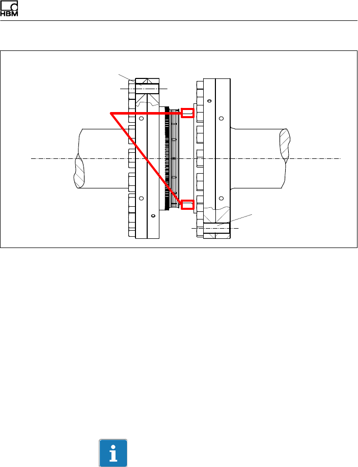
Mechanischer Einbau
T40FH A4429-1.0 HBM: public 27
Innensechskantschraube (Z) DIN EN ISO 4762 (12.9)
Innensechskant
schraube (Z) DIN EN
ISO 4762 (12.9)
Messzone
Abb. 5.5 Verschraubung des Rotors
2. Verwenden Sie für die Verschraubung des Flanschs
(siehe Abb. 5.5) Innensechskantschrauben DIN EN
ISO 4762 der Festigkeitsklasse 12.9 in geeigneter
Länge (abhängig von der Anschlussgeometrie, siehe
Tab. 5.1 auf Seite 28).
Wir empfehlen Zylinderschrauben DIN EN ISO4762,
geschwärzt, glatter Kopf, zulässige Maß‐ und Formab
weichung nach DIN ISO4759, Teil1, Produktklasse A.
3. Ziehen Sie alle Schrauben mit dem vorgeschriebenen
Drehmoment an (Tab. 5.1 auf Seite 28).
4. Entfernen Sie nun die Transport‐ und Montageöse(n).
Wichtig
Bewahren Sie die Transport‐ und Montageösen für eine
spätere Demontage gut auf.
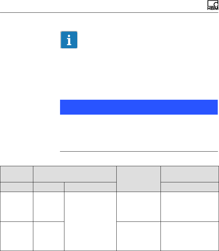
Mechanischer Einbau
28 A4429-1.0 HBM: public T40FH
Wichtig
Kleben Sie die Verbindungsschrauben mit einer Schrau
bensicherung (mittelfest, z.B. von LOCTITE) in das Ge
gengewinde ein, um einen Vorspannverlust durch
Lockern auszuschließen, falls Wechsellasten zu erwarten
sind.
Hinweis
Halten Sie die maximale Einschraubtiefe nach Tab. 5.1,
Seite 28 unbedingt ein. Andernfalls kann es zu erhebli
chen Messfehlern durch Drehmomentnebenschluss oder
zur Beschädigung des Aufnehmers kommen.
Mess
bereich
Befestigungsschrauben Anzahl der
Schrauben
pro Flansch
Vorgeschriebenes
Anzugsmoment
kNVm Z16) Festigkeitsklasse NVm
100
150
150
M30
12.9
16 2450
200
250
300
M36 18 4250
16) DIN EN ISO4762; schwarz/geölt/mges=0,125
Tab. 5.1 Befestigungsschrauben

Mechanischer Einbau
T40FH A4429-1.0 HBM: public 29
Wichtig
Trockene Schraubenverbindungen können abweichende,
höhere Reibfaktoren zur Folge haben (siehe z.B.
VDI 2230). Dadurch ändern sich die erforderlichen
Anzugsmomente.
Die erforderlichen Anzugsmomente können sich auch
ändern, falls Sie Schrauben mit anderer Oberfläche oder
anderer Festigkeitsklasse als in Tab. 5.1 angegeben
verwenden, da dies den Reibfaktor beeinflusst.
5.7 Montage des Stators
Im Anlieferungszustand ist der Stator betriebsfertig mon
tiert. Sie können das obere Antennensegment vom Stator
trennen, zum Beispiel bei Wartungsarbeiten, oder um
eine leichtere Montage des Stators zu ermöglichen.

Mechanischer Einbau
30 A4429-1.0 HBM: public T40FH
Bohrung Ø 6,5 mm zur
Fixierung des
Antennensegments
Statorgehäuse
oben
Antennensegment‐
Schrauben mit
Unterlegscheiben
(M4+M5)
unten
Antennensegmente
Antennensegment‐
Schrauben mit
Unterlegscheiben
(M4+M5)
Abb. 5.6 Verschraubung der Antennensegmente am Stator
1. Lösen und entfernen Sie die beiden Verschraubungen
(M4+M5) am oberen Antennensegment.
Zwischen den Antennensegmenten sind Fächerschei
ben (M4+M5) angeordnet: Achten Sie darauf, dass
diese nicht verloren gehen.
2. Montieren Sie das Statorgehäuse auf einer geeigne
ten Grundplatte im Wellenstrang, sodass ausrei
chende Einstellmöglichkeiten in horizontaler und
vertikaler Richtung vorhanden sind. Ziehen Sie die
Schrauben aber noch nicht fest.
3. Montieren Sie nun das unter Punkt 1. entfernte obere
Antennensegment mit den vier Innensechskant
schrauben auf das untere Antennensegment.

Mechanischer Einbau
T40FH A4429-1.0 HBM: public 31
Achten Sie darauf, dass zwischen den Antennenseg
menten die Fächerscheiben eingelegt sind (diese
sorgen für einen definierten Übergangswiderstand)!
Wichtig
Um eine einwandfreie Funktion zu gewährleisten,
müssen die Fächerscheiben (A5,3‐FST DIN 6798 ZN/ver
zinkt) nach dreimaligem Lösen der Antennen‐Verschrau
bung erneuert werden.
4. Ziehen Sie nun alle Verschraubungen der Antennen
segmente mit einem Anzugsmoment von 5N⋅m an.
5. Richten sie dann die Antenne zum Rotor so aus, dass
die Antenne den Rotor etwa koaxial umschließt und
der Antennendraht in axialer Richtung die gleiche
Position wie die Mitte der Übertragerwicklung auf dem
Rotor aufweist.
Um die Ausrichtung zu erleichtern, sollten die
Außenkante des Stator‐Antennensegments und die
Außenkante des Stator‐Wicklungsträgers auf einer
Linie liegen (fluchten). Beachten Sie die in den techni
schen Daten angegebenen zulässigen Ausrichtungs
toleranzen.
6. Ziehen Sie jetzt die Verschraubung des Statorgehäu
ses fest an.
Vermeidung von Axialschwingungen des Stators
Je nach Betriebsbedingungen kann es vorkommen, dass
der Stator zum Schwingen angeregt wird. Dieser Effekt
ist abhängig von:
Sder Drehzahl,

Mechanischer Einbau
32 A4429-1.0 HBM: public T40FH
Sdem Antennendurchmesser (abhängig vom Mess
bereich),
Sder Konstruktion des Maschinenbettes.
Wichtig
Um Axialschwingungen zu vermeiden, ist dem Dreh
momentaufnehmer ein Klemmstück beigelegt, mit dem
der Antennenring abgestützt werden kann. Hierzu befin
det sich am oberen Antennensegment Bohrung mit
einem Durchmesser von 6,5 mm, die zur Aufnahme der
Klemmeinrichtung dient (siehe Abb. 5.7).
Gleichzeitig ist in diesem Fall eine Abstützung der Kabel
stecker (nicht im Lieferumfang enthalten) erforderlich, ein
Konstruktionsbeispiel zeigt Abb. 5.9.
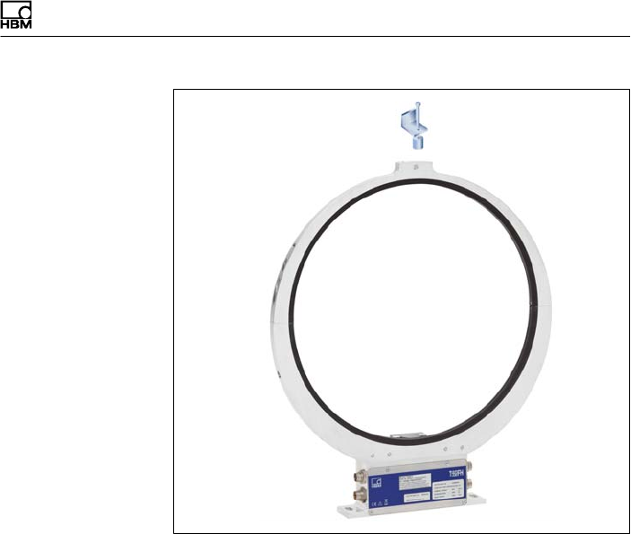
Mechanischer Einbau
T40FH A4429-1.0 HBM: public 33
Abb. 5.7 Konstruktionsbeispiel für die Abstützung des
Antennenrings
7. Befestigen Sie das klemmstück mit der beigelegten
Verschraubung nach Abb. 5.8. Klemmen Sie ein
geeignetes Abstützelement (z.B. einen Gewindestab
Ø 3 - 6 mm) zwischen Ober- und Unterteil des
Klemmstücks und ziehen Sie die Klemmschrauben
an.
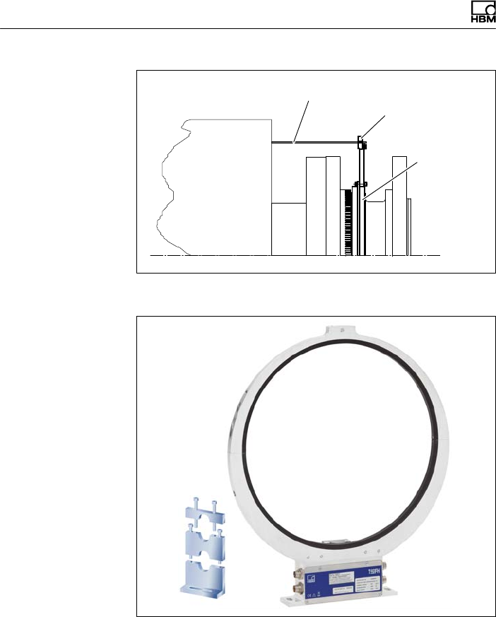
Mechanischer Einbau
34 A4429-1.0 HBM: public T40FH
Kundenseitige Abstützung
Klemmstück
Antennenring
Abb. 5.8 Abstützen des Antennenrings
Abb. 5.9 Konstruktionsbeispiel für Steckerklemmen (für zwei
Stecker)
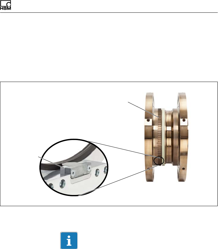
Mechanischer Einbau
T40FH A4429-1.0 HBM: public 35
5.8 Drehzahlmesssystem
Der Rotor wird bereits standardmäßig mit einem Zahn
kranz für das Drehzahlmesssystem geliefert. Optional ist
der Stator mit einem Sensorkopf für die Abtastung der
mechanischen Inkremente (Zahnkranz) ausgestattet.
Sensorkopf
für Drehzahl
messung
(optional)
Zahnkranz
Abb. 5.10 Drehmomentaufnehmer mit Drehzahlmessung
(optional)
Wichtig
Das Drehzahlmesssystem verwendet ein magnetisches
Messprinzip. Treffen Sie bei Anwendungen, bei denen
hohe magnetische Feldstärken auftreten können, z.B.
bei Wirbelstrombremsen, geeignete Maßnahmen, damit
die maximal zulässige magnetische Feldstärke nicht
überschritten wird (siehe Kapitel 15 „Technische Daten“,
Seite 69).

Mechanischer Einbau
36 A4429-1.0 HBM: public T40FH
Ausrichtung Stator (Drehzahlmesssystem)
Für den einwandfreien Messbetrieb muss der Drehzahl
sensor an einer definierten Stelle zum Zahnkranz des
Rotors positioniert werden. Bei exakter radialer und
axialer Ausrichtung des Stators zur Drehmoment
messung ist auch das Drehzahlmesssystem richtig aus
gerichtet.
Axiale Ausrichtung:
Werksseitig ist der Sensorkopf des Drehzahlmess
systems so justiert, dass sich bei exakt axial ausgerichte
tem Stator (Antennenring liegt genau über der Über
tragerwicklung des Rotors) der Drehzahlsensor sich in
der richtigen Position zum Zahnkranz des Rotors
befindet.
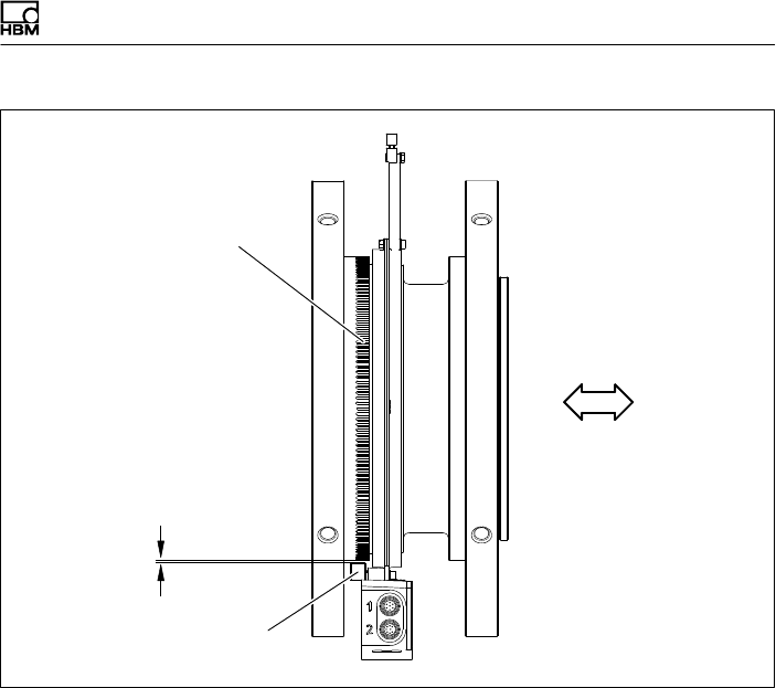
Mechanischer Einbau
T40FH A4429-1.0 HBM: public 37
Zahnkranz
Drehzahlsensor
Radialer
Abstand
Axiale Ausrichtung
Abb. 5.11 Seitenansicht
Radiale Ausrichtung:
Rotorachse und Achse des Drehzahlsensors müssen in
einer Linie rechtwinklig zur Statorplattform stehen. Für
die radiale Ausrichtung ist der radiale Nennabstand maß
gebend (siehe Abb. 5.11). Der optimale Abstand beträgt
2,5 mm und wird erreicht, wenn Rotor und Stator exakt
radial zueinander ausgerichtet sind.
Elektrischer Anschluss
38 A4429-1.0 HBM: public T40FH
6 Elektrischer Anschluss
6.1 Allgemeine Hinweise
SAchten Sie bei Kabelverlängerungen auf eine ein
wandfreie Verbindung mit geringstem Übergangs
widerstand und guter Isolation.
SAlle Kabel‐Steckverbindungen oder Überwurfmuttern
müssen fest angezogen werden.
Wichtig
Aufnehmer‐Anschlusskabel von HBM mit montierten Ste
ckern sind ihrem Verwendungszweck entsprechend ge
kennzeichnet (Md oder n). Beim Kürzen der Kabel,
Einziehen in Kabelkanälen oder Verlegen in Schalt
schränken kann diese Kennzeichnung verloren gehen
oder verdeckt sein. Kennzeichnen Sie daher die Kabel in
diesen Fällen vor der Verlegung.
6.2 EMV‐Schutz
Wichtig
Die Aufnehmer sind gemäß EG‐Richtlinien EMV‐geprüft
und mit einer CE‐Zertifizierung gekennzeichnet. Sie müs
sen jedoch den Schirm des Anschlusskabels am
schirmenden Gehäuse der Elektronik anschließen, um
den EMV‐Schutz der Messkette zu erreichen.

Elektrischer Anschluss
T40FH A4429-1.0 HBM: public 39
Die Signalübertragung zwischen Übertragerkopf und Ro
tor erfolgt rein digital und ist durch spezielle elektronische
Kodierungsverfahren gegen elektromagnetische Be
einflussungen geschützt.
Der Kabelschirm wird mit dem Aufnehmergehäuse ver
bunden. Dadurch ist das Messsystem (ohne Rotor) von
einem Faradayschen Käfig umschlossen, wenn die Schir
mung an beiden Kabelenden flächig aufgelegt wird. Se
hen Sie bei anderen Anschlusstechniken im Litzenbe
reich eine EMVfeste Abschirmung vor, bei der ebenfalls
die Schirmung flächig aufgelegt ist (siehe auch
HBMGreenlineInformation, Druckschrift i1577).
Elektrische und magnetische Felder verursachen oft eine
Einkopplung von Störspannungen in den Messkreis.
Deshalb:
SVerwenden Sie nur abgeschirmte, kapazitätsarme
Messkabel (HBM‐Kabel erfüllen diese Bedingungen).
SVerwenden Sie ausschließlich Stecker, die den
EMVRichtlinien entsprechen.
SLegen Sie die Messkabel nicht parallel zu Starkstrom‐
und Steuerleitungen. Falls das nicht möglich ist,
schützen Sie das Messkabel, z.B. durch Stahlpanzer
rohre.
SMeiden Sie Streufelder von Trafos, Motoren und
Schützen.
SErden Sie Aufnehmer, Verstärker und Anzeigegerät
nicht mehrfach.
SSchließen Sie alle Geräte der Messkette an den glei
chen Schutzleiter an.
SFalls Störungen durch Potenzialunterschiede (Aus
gleichsströme) auftreten, trennen Sie am Messver
stärker die Verbindungen zwischen Versorgungs
spannungsnull und Gehäusemasse und legen Sie

Elektrischer Anschluss
40 A4429-1.0 HBM: public T40FH
eine Potenzialausgleichsleitung zwischen Statorge
häuse und Messverstärkergehäuse (Kupferleitung,
mindestens 10mm2 Leitungsquerschnitt).
SSollten Potenzialunterschiede zwischen Rotor und
Stator der Maschine auftreten, z.B. durch unkon
trolliertes Ableiten, hilft meist das eindeutige Erden
des Rotors z.B. mittels Schleifer. Der Stator muss auf
das gleiche (Erd‐)Potenzial gelegt werden.
6.3 Steckerbelegung Option 4, Code SU2,
DU2, HU2
Am Statorgehäuse befinden sich zwei 7‐polige Stecker,
ein 8‐poliger und ein 16‐poliger Stecker.
Die Anschlüsse der Versorgungsspannung und des
Shuntsignals der Stecker 1 und 3 sind jeweils mitein
ander galvanisch verbunden aber mit Dioden gegen Aus
gleichsströme geschützt. Die Anschlüsse der Versor
gungsspannung sind zusätzlich mit einer
selbstrückstellenden Sicherung (Multifuse) gegen
Überlast durch den Stator geschützt.
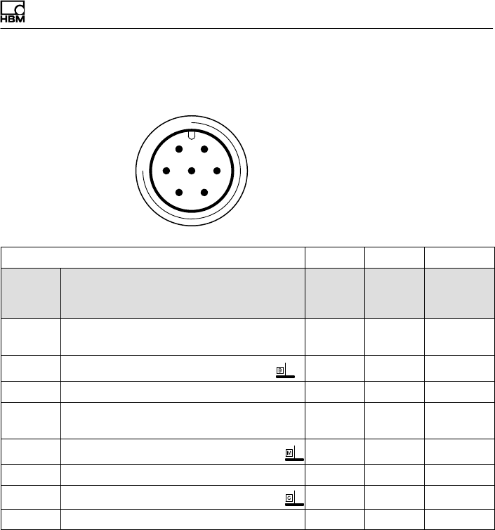
Elektrischer Anschluss
T40FH A4429-1.0 HBM: public 41
Belegung Stecker 1 - Versorgungsspannung und
Frequenz‐Ausgangssignal
61
572
43
Gerätestecker
Draufsicht
KAB153 KAB149 KAB1781)
Stecker
Pin
Belegung Ader
farbe
D‐SUB‐
Stecker
Pin
HD‐SUB‐
Stecker
Pin
1Messsignal Drehmoment
(Frequenzausgang; 5 V2,3)ws 13 5
2Versorgungsspannung 0 V sw 5 -
3Versorgungsspannung 18 V …30 V bl 6 -
4Messsignal Drehmoment
(Frequenzausgang; 5 V2,3)rt 12 10
5Messsignal 0 V; symmetrisch gr 8 6
6Shuntsignal‐Auslösung 5 V … 30 V gn 14 15
7Shuntsignal 0 V gr 8
Schirm an Gehäusemasse
1) Brücke zwischen 4 +9
2) Komplementäre Signale RS‐422; ab 10m Kabellänge empfehlen wir einen Abschlusswiderstand
mit R = 120Ohm zwischen den Adern (ws) und (rt).
3) RS‐422: Pin 1 entspricht A, Pin 4 entspricht B.
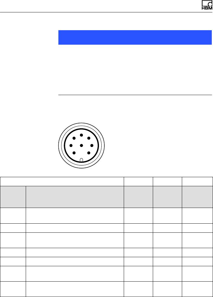
Elektrischer Anschluss
42 A4429-1.0 HBM: public T40FH
Hinweis
Die Drehmoment‐Messflansche sind nur für den Betrieb
mit DC‐Versorgungsspannung vorgesehen. Sie dürfen
nicht an ältere HBM‐Messverstärker mit Rechteck‐Spei
sung angeschlossen werden. Hier könnte es zur Zerstö
rung von Widerständen der Anschlussplatte bzw.
anderen Fehlern in den Messverstärkern kommen.
Belegung Stecker 2 - Drehzahl-Messsystem
6
1
5
7
2
4
38
Gerätestecker
Draufsicht
KAB154 KAB150 KAB1791)
Stecker
Pin
Belegung Ader
farbe
D-SUB-
Stecker
Pin
HD-SUB-
Stecker
Pin
1Messsignal Drehzahl 2) (Impulsfolge,
5V; 0°)rt 12 10
2Nicht belegt bl - -
3Messsignal Drehzahl 2 (Impulsfolge,
5V; um 90° phasenverschoben) gr 15 8
4Nicht belegt sw - -
5Nicht belegt vi - -
6Messsignal Drehzahl 2)
(Impulsfolge, 5V; 0°)ws 13 5
7Messsignal Drehzahl 2) (Impulsfolge,
5V; um 90° phasenverschoben) gn 14 7
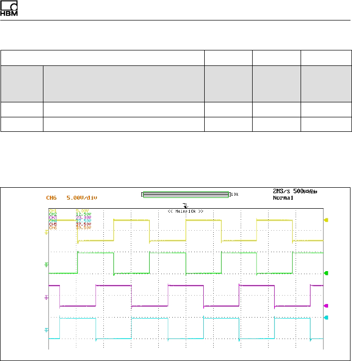
Elektrischer Anschluss
T40FH A4429-1.0 HBM: public 43
KAB1791)
KAB150KAB154
HD-SUB-
Stecker
Pin
D-SUB-
Stecker
Pin
Ader
farbe
BelegungStecker
Pin
8 Betriebsspannungsnull sw/bl 3) 8 6
Schirm an Gehäusemasse
1) Brücke zwischen 4 + 9
2) Komplementäre Signale RS‐422; ab 10m Kabellänge empfehlen wir einen Abschlusswiderstand
mit R = 120Ohm.
3) Bei KAB163 / KAB164 Aderfarbe braun (bn)
Pin 1
Pin 6
Pin 3
Pin 7
Abb. 6.1 Drehzahlsignale an Stecker 2 (Drehzahl in
Pfeilrichtung)
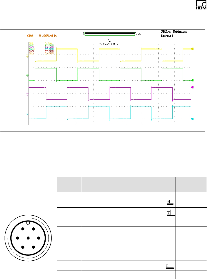
Elektrischer Anschluss
44 A4429-1.0 HBM: public T40FH
Pin 1
Pin 6
Pin 3
Pin 7
Abb. 6.2 Drehzahlsignale an Stecker 2 (Drehzahl gegen
Pfeilrichtung)
Belegung Stecker 3 - Spannungsversorgung und
Spannungs-Ausgangssignal
61
572
43
Gerätestecker
Draufsicht
Stecker
Pin
Belegung Aderfarbe
1Messsignal Drehmoment
(Spannungsausgang; ±10 V) ws
2Versorgungsspannung 0 V; sw
3Versorgungsspannung 18 V …30 V bl
4Messsignal Drehmoment
(Spannungsausgang ±10 V) rt
5Nicht belegt gr
6Shuntsignal‐Auslösung 5 V …30 V gn
7Shuntsignal 0 V; gr
Schirm an Gehäusemasse
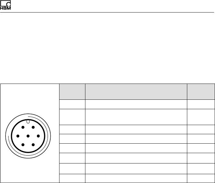
Elektrischer Anschluss
T40FH A4429-1.0 HBM: public 45
Belegung Stecker 4
TMC - nur für HBM‐interne Verbindung zu den Torque-In
terface-Modulen der TIM-Familie.
6.4 Steckerbelegung Option 3, Code PNJ
61
572
43
Binder 723
Draufsicht
Stecker
Pin
Belegung Ader
farbe
1Messsignal (+) UAws
2Brückenspeisespannung (-) UB und
TEDS
sw
3Brückenspeisespannung (+) UBbl
4Messsignal (-) UArt
5Nicht belegt -
6Fühlerleitung (+) gn
7Fühlerleitung (-) und TEDS gr
Schirm an Gehäusemasse
6.5 Versorgungsspannung
(SU2, DU2, HU2)
Der Aufnehmer wird mit einer Schutzkleinspannung
(Nenn‐Versorgungsspannung 18 … 30VDC) betrieben.
Sie können einen oder mehrere Drehmoment‐Messflan
sche innerhalb eines Prüfstandes gleichzeitig versorgen.
Treffen Sie zusätzliche Vorkehrungen für die Ableitung
von Überspannungen, falls Sie das Gerät an einem
Gleichspannungsnetz1) betreiben möchten.
Die Hinweise dieses Kapitels beziehen sich auf den aut
arken Betrieb des T40FH ohne HBM‐Systemlösungen.
1) Verteilsystem für elektrische Energie mit einer größeren räumlichen Ausdehnung (z. B. über
mehrere Prüfstände) das eventuell auch Verbraucher mit großen Nennströmen versorgt.
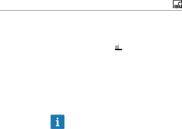
Elektrischer Anschluss
46 A4429-1.0 HBM: public T40FH
Die Versorgungsspannung ist von den Signalausgängen
und den Shuntsignal‐Eingängen galvanisch getrennt.
Schließen Sie eine Schutzkleinspannung von 18V …
30V an Pin 3 (+) und Pin 2 ( ) der Stecker 1 oder 3 an.
Wir empfehlen, das HBM‐Kabel KAB 8/00‐2/2/2 und ent
sprechende Buchsen zu verwenden (siehe Zubehör,
Seite 67). Das Kabel darf bei Spannungen ≥24V bis zu
50m, ansonsten bis zu 20m lang sein.
Wird die zulässige Kabellänge überschritten, können Sie
die Versorgungsspannung über zwei Anschlusskabel
(Stecker 1 und 3) parallel zuführen. Damit erreichen Sie
eine Verdoppelung der zulässigen Länge. Installieren Sie
andernfalls ein Netzteil vor Ort.
Wichtig
Im Einschaltmoment kann ein Strom von bis zu 4 A
fließen und damit Netzteile mit elektronischer
Strombegrenzung ausschalten.
6.6 Versorgungsspannung (Option 3,
Code PNJ)
Als Zubehör ist ein konfektioniertes 6‐adriges Aufnehmer‐
Anschlusskabel mit freien Enden erhältlich.
Verlängerungskabel sollten geschirmt und kapazitätsarm
sein. HBM bietet hierfür speziell die Kabel
1-KAB0304A-10 (konfektioniert) und KAB8/00‐2/2/2
(Meterware) an.
Die Anschlussbelegung entnehmen Sie bitte der Tabelle
im Kapitel 6.4.
Die Anschlussbelegungen verstärkerseitig entnehmen
Sie bitte den Unterlagen des jeweiligen Verstärkers.

Elektrischer Anschluss
T40FH A4429-1.0 HBM: public 47
7 Aufnehmer‐Identifikation TEDS
(Option 3, Code PNJ)
TEDS steht für “Transducer Electronic Data Sheet”. Im
Aufnehmer kann ein elektronisches Datenblatt nach der
Norm IEEE1451.4 gespeichert werden, welches das au
tomatische Einstellen des Messverstärkers ermöglicht.
Ein entsprechend ausgestatteter Messverstärker liest die
Kenndaten des Aufnehmers aus, übersetzt diese in ei
gene Einstellungen und die Messung kann gestartet wer
den.
Am Steckeranschluss PIN 7 gegen PIN 2 steht das digi
tales Identifikationssystem zur Verfügung. Zum Einspei
chern der Daten dient der TEDS‐Editor von HBM. Dieser
ist Bestandteil der HBM‐Software “MGCplus‐Setup‐Assi
stent”. Mit dem Editor können Sie verschiedene Benut
zerrechte verwalten und so die grundlegenden Aufneh
merdaten gegen versehentliches Überschreiben
schützen.
7.1 Hierarchie der Nutzerrechte
7.1.1 Standardrechte (Stufe USR)
Diese Stufe betrifft Rechte, die der Anwender des Auf
nehmers braucht, um Einträge zu ändern, die vom Ein
satzfall abhängen.

Elektrischer Anschluss
48 A4429-1.0 HBM: public T40FH
7.1.2 Kalibrierrechte (Stufe CAL)
Diese Stufe betrifft Rechte, die z. B. ein Kalibrierlabor
benötigt, wenn der Kennwert im TEDS‐Speicher geändert
werden soll.
7.1.3 Administratorrechte (Stufe ID)
Administratorrechte in Bezug auf TEDS sind für den Sen
sorhersteller vorgesehen.
Zum Ändern der unterschiedlichen Einträge in den Tem
plates sind unterschiedliche Nutzerrechte erforderlich, die
sich auch von Eintrag zu Eintrag innerhalb eines Templa
tes unterscheiden können.
7.2 Inhalt des TEDS‐Speicher nach
IEEE 1451.4
Die Informationen im TEDS‐Speicher sind in Bereiche
organisiert, in denen die Ablage bestimmter Gruppen von
Daten in Tabellenform vorstrukturiert ist.
Im TEDS‐Speicher selbst sind nur die eingetragenen
Werte gespeichert. Die Zuordnung, wie der jeweilige Zah
lenwert zu interpretieren ist, erfolgt durch die Firmware
des Messverstärkers. Dadurch ist der Speicherbedarf im
TEDS‐Speicher sehr gering. Der Speicherinhalt ist in 3
Bereiche unterteilt:
Bereich 1
Eine weltweit eindeutige TEDS‐Identifikationsnummer
(nicht änderbar).

Elektrischer Anschluss
T40FH A4429-1.0 HBM: public 49
Bereich 2
Der Basisbereich (Basic TEDS) dessen Aufbau durch die
Norm IEEE 1451.4 definiert ist. Hier stehen Aufnehmer
typ, Hersteller und Seriennummer des Aufnehmers.
Beispiel:
Inhalt TEDS mit der Identitätsnummer für den Sensor
T40FH/150 kN@m mit der Serien‐Nr. 123456, hergestellt
im November 2005
TEDS
Manufacturer HBM
Model T40FH
Version letter
Version number
Serial number 123456
Bereich 3
In diesem Bereich stehen Daten, die der Hersteller bzw.
Anwender festlegt.
Für den Drehmoment‐Messflansch T40FH hat HBM be
reits das Template Bridge Sensor und das Template
Channel name beschrieben.
Weitere Templates wie z. B. das Template Signal Condi
tioning können vom
Anwender zusätzlich beschrieben werden.

Elektrischer Anschluss
50 A4429-1.0 HBM: public T40FH
Template: Bridge Sensor
Parameter Wert1)Ein
heit
Erforderl.
Nutzer
rechte
Erklärung
Transducer Elec
trical Signal Type
Bridge
Sensor
ID
Minimum Torque 0.000 N@m CAL Physikalische Mess
größe und Einheit wer
den beim Anlegen des
Templates definiert und
sind dann nicht mehr än
derbar.
Maximum Torque 150000 N@m CAL
Minimum Electri
cal
Value
0.0000m V/V CAL Differenz dieser Werte ist
der Kennwert laut HBM
Prüfprotokoll oder aus
Kalibrierung
Maximum Electri
cal Value
1.8245m V/V CAL
Mapping Method Linear Dieser Eintrag kann nicht
geändert werden
Bridge type Full ID Brückentyp. “Full” für
Vollbrücke.
Impedance of
each bridge ele
ment
1550+-100 Ohm ID Eingangswiderstand laut
HBM‐Datenblatt
Response Time 1.0000000u s ID Für HBM‐Aufnehmer be
deutungslos
Excitation Level
(Nominal)
5.0 V ID Nennspeisespannung
laut HBM‐Datenblatt
Excitation Level
(Minimum)
2.5 V ID Untergrenze des Ge
brauchsbereichs der
Speisespannung laut
HBM‐Datenblatt

Elektrischer Anschluss
T40FH A4429-1.0 HBM: public 51
Template: Bridge Sensor
ErklärungErforderl.
Nutzer
rechte
Ein
heit
Wert1)
Parameter
Excitation Level
(Maximum)
12.0 V ID Obergrenze des Ge
brauchsbereichs der
Speisespannung laut
HBM‐Datenblatt
Calibration Date 1-Nov-2005 CAL Datum der letzten Kali
brierung bzw. Erstellung
des Prüfprotokolls (wenn
keine Kalibrierung durch
geführt), bzw. der Ein
speicherung der TEDS‐
Daten (wenn lediglich
Datenblatt‐Nennwerte
verwendet wurden).
Format: Tag-Monat-Jahr.
Kürzel für die Monate:
Jan, Feb, Mrz, Apr, Mai,
Jun, Jul, Aug, Sep, Okt,
Nov, Dez.
Calibration Initials HBM CAL Initialen des Kalibrierers
bzw. der durchführenden
Stelle der Kalibrierung.
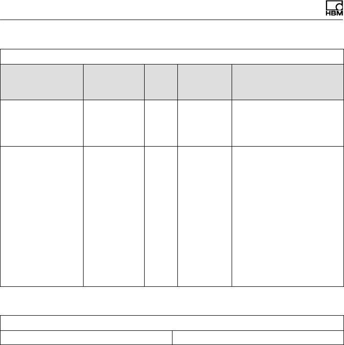
Elektrischer Anschluss
52 A4429-1.0 HBM: public T40FH
Template: Bridge Sensor
ErklärungErforderl.
Nutzer
rechte
Ein
heit
Wert1)
Parameter
Calibration Period
(Days)
730 days CAL Frist für die Rekalibrie
rung, zu rechnen ab dem
unter Calibration Date
angegebenem Datum.
Measurement lo
cation ID
0 USR Identifikationsnummer für
die Messstelle.
Kann anwendungsab
hängig vergeben werden.
Mögliche Werte: eine
Zahl von 0 bis 2047.
Wenn das nicht aus
reicht, kann für diesen
Zweck auch das HBM‐
Template
Channel Comment ein
gesetzt werden.
1) Beispielhafte Werte für einen HBM‐Drehmoment‐Messflansch T40FH/150 kN@m
Template: HBM Channel Name
Channel name T40FH/150 kNm
Beim Anlegen des Templates Bridge Sensor durch den
Hersteller werden physikalische Messgröße und physika
lische Einheit festgelegt.
Die verfügbare Einheit ist in der IEEE-Norm für die jewei
lige Messgröße festgelegt. Dies ist für die Messgröße
Drehmoment die Einheit “N@m”.
Weiter ist bereits beim Anlegen zwischen den Varianten
”Full precision”, ”mV/V” und ”uV/V” für die Genauigkeit
der in TEDS abgebildeten Aufnehmerkennlinie zu wäh
len.

Elektrischer Anschluss
T40FH A4429-1.0 HBM: public 53
Werkseinstellung ist ”Full Precision” um die volle digitale
Auflösung nutzen zu können. Diese Wahl empfehlen wir
auch Anwendern, die den TEDS‐Speicher selbst pro
grammieren.
Shuntsignal
54 A4429-1.0 HBM: public T40FH
8 Shuntsignal
Der Drehmoment‐Messflansch T40FH liefert ein
elektrisches Shuntsignal, das bei Messketten mit HBM‐
Komponenten vom Verstärker aus aktiviert werden kann.
Der Aufnehmer erzeugt ein Shuntsignal von ca. 50 % des
Nenndrehmoments, der genaue Wert ist auf dem Typen
schild vermerkt. Stellen Sie nach der Aktivierung das Ver
stärkerausgangssignal auf das Shuntsignal des ange
schlossenen Aufnehmers ein, ist der Messverstärker an
den Aufnehmer angepasst.
Information
Beim Messen des Shuntsignals sollte der Aufnehmer un
belastet sein, da das Shuntsignal additiv aufgeschaltet
wird.
Auslösen des Shuntsignals
Durch Anlegen einer Schutzkleinspannung von 5 … 30V
an Pin 6 (+) und 7 ( ) am Stecker 1 oder 3 wird das
Shuntsignal ausgelöst.
Die Nennspannung für das Auslösen des Shuntsignals
beträgt 5V (Auslösen bei U > 2,5V), bei Spannungen
kleiner 0,7V ist der Aufnehmer im Messbetrieb. Die ma
ximal zulässige Spannung beträgt 30V, bei Nenn
spannung beträgt die Stromaufnahme ca. 2mA, bei Ma
ximalspannung ca. 18mA. Spannung für das Auslösen
des Shuntsignals ist galvanisch von der Versorgungs‐
und der Messspannung getrennt.

Shuntsignal
T40FH A4429-1.0 HBM: public 55
Tipp
Bei HBM‐Systemlösungen kann das Shuntsignal vom
Messverstärker bzw. über die Bedien‐Software ausgelöst
werden.
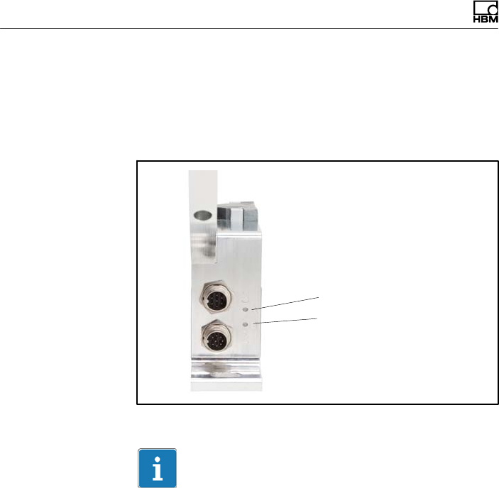
Funktionsprüfung
56 A4429-1.0 HBM: public T40FH
9 Funktionsprüfung
Durch LEDs am Stator kann die Funktion von Rotor und
Stator überprüft werden.
LED A Rotorstatus
LED B Statorstatus
Abb. 9.1 LEDs am Statorgehäuse
Wichtig
Der Drehmomentaufnehmer benötigt nach Anlegen der
Versorgungsspannung noch bis zu 4 Sekunden, bevor er
betriebsbereit ist.

Funktionsprüfung
T40FH A4429-1.0 HBM: public 57
9.1 Rotorstatus, LED A (obere LED)
Farbe Bedeutung
Grün (pulsierend) Interne Rotor‐Spannungswerte o.k.
Orange blinkend Fehljustierung von Rotor und Stator (zunehmende Blinkfre
quenz zeigt den Grad der Dejustierung an)
=> Ausrichtung Rotor-Stator korrigieren
Orange pulsierend Rotorzustand nicht bestimmbar
=> Ausrichtung Rotor-Stator korrigieren
Falls die LED daraufhin immer noch orange pulsiert, liegt
möglicherweise ein Hardwaredefekt vor. Die Messignale neh
men den Pegel des Fehlerzustands an.
Rot (pulsierend) Rotor‐Spannungswerte nicht in Ordnung.
=> Ausrichtung Rotor-Stator korrigieren
Falls die LED daraufhin immer noch rot pulsiert, liegt mögli
cherweise ein Hardwaredefekt vor. Die Messsignale nehmen
den Pegel des Fehlerzustands an.
Pulsierend bedeutet, die LED wird pro Sekunde für ca.
20ms dunkel geschaltet (Lebendsignal); damit ist das
Funktionieren des Aufnehmers erkennbar.
9.2 Statorstatus, LED B (untere LED)
Farbe Bedeutung
Grün
(dauerhaft leuchtend)
Messsignal‐Übertragung und interne Stator‐Spannungen o.k.
Grün, zeitweise
orange.
Bei vielen Synchroni
sationsfehlern:
dauerhaft orange
Bei fehlerhafter Übertragung von y5 Messwerten in Folge bis
zum Ende der fehlerhaften Übertragung orange. Die Messsi
gnale nehmen für die Dauer des Übertragungsfehlers + ca.
weitere 3,3ms den Pegel des Fehlerzustands an.

Funktionsprüfung
58 A4429-1.0 HBM: public T40FH
BedeutungFarbe
Orange
(dauerhaft leuchtend)
Dauerhaft gestörte Übertragung, die Messignale nehmen den
Pegel des Fehlerzustands an. (fout = 0 Hz, Uout = Fehlerle
vel).
=> Ausrichtung Rotor-Stator korrigieren.
Rot
(dauerhaft leuchtend)
Interner Statorfehler, die Messsignale nehmen den Pegel des
Fehlerzustands an (fout = 0 Hz, Uout = Fehlerlevel).

Belastbarkeit
T40FH A4429-1.0 HBM: public 59
10 Belastbarkeit
Das Nenndrehmoment darf statisch bis zum Grenzdreh
moment überschritten werden. Wird das Nenndreh
moment überschritten, sind weitere irreguläre Belas
tungen nicht zulässig. Hierzu zählen Längskräfte,
Querkräfte und Biegemomente. Die Grenzwerte finden
Sie im Kapitel 15 „Technische Daten“ auf Seite 69.
Messen dynamischer Drehmomente
Der Drehmoment‐Messflansch eignet sich zum Messen
statischer und dynamischer Drehmomente. Beim Messen
dynamischer Drehmomente ist zu beachten:
SDie für statische Messungen durchgeführte
Kalibrierung des T40FH gilt auch für dynamische
Drehmomentmessungen.
SDie Eigenfrequenz f0 der mechanischen Messanord
nung hängt von den Trägheitsmomenten J1 und J2 der
angeschlossenen Drehmassen sowie der Drehsteifig
keit des T40FH ab.
Die Eigenfrequenz f0 der mechanischen Messanordnung
lässt sich aus folgender Gleichung überschlägig
bestimmen:
f0+1
2p· cT·ǒ1
J1
)1
J2Ǔ
Ǹf0= Eigenfrequenz in Hz
J1, J2= Massenträgheitsmoment in kg⋅m2
cT= Drehsteifigkeit in N⋅m/rad
SDie zulässige mechanische Schwingbreite (Spitze-
Spitze) finden Sie ebenfalls in den technischen Daten.
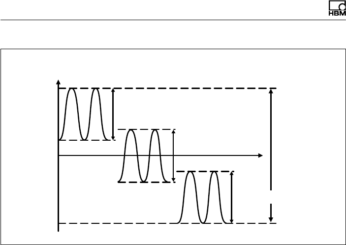
Belastbarkeit
60 A4429-1.0 HBM: public T40FH
0
+ Mnom
200 % Schwing
breite
- Mnom
Nenndrehmoment Mnom in %
Zeit t
Schwingbreite
Schwingbreite
Schwingbreite
Abb. 10.1 Zulässige dynamische Belastung

Wartung
T40FH A4429-1.0 HBM: public 61
11 Wartung
Die Drehmoment‐Messflansche T40FH sind wartungsfrei.
Entsorgung und Umweltschutz
62 A4429-1.0 HBM: public T40FH
12 Entsorgung und Umweltschutz
Alle elektrischen und elektronischen Produkte müssen
als Sondermüll entsorgt werden. Die ordnungsgemäße
Entsorgung von Altgeräten beugt Umweltschäden und
Gesundheitsgefahren vor.
Gesetzlich vorgeschriebene Kennzeichnung zur
Entsorgung
Elektrische und elektronische Geräte, die dieses Symbol
tragen, unterliegen der europäischen Richtlinie
2002/96/EG über elektrische und elektronische Altgeräte.
Das Symbol weist darauf hin, dass nicht mehr ge
brauchsfähige Altgeräte gemäß den europäischen Vor
schriften für Umweltschutz und Rohstoffrückgewinnung
getrennt von regulärem Hausmüll zu entsorgen sind.
Da die Entsorgungsvorschriften von Land zu Land unter
schiedlich sind, bitten wir Sie, im Bedarfsfall Ihren Liefe
ranten anzusprechen, welche Art von Entsorgung oder
Recycling in Ihrem Land vorgeschrieben ist.
Verpackungen
Die Originalverpackung der HBM‐Geräte besteht aus re
cyclebarem Material und kann der Wiederverwertung
zugeführt werden. Bewahren Sie die Verpackung jedoch
mindestens für den Zeitraum der Gewährleistung auf. Bei
Reklamationen muss der Drehmoment‐Messflansch in
der Originalverpackung zurückgesandt werden.
Aus ökologischen Gründen sollte auf den Rücktransport
der leeren Verpackungen an uns verzichtet werden.
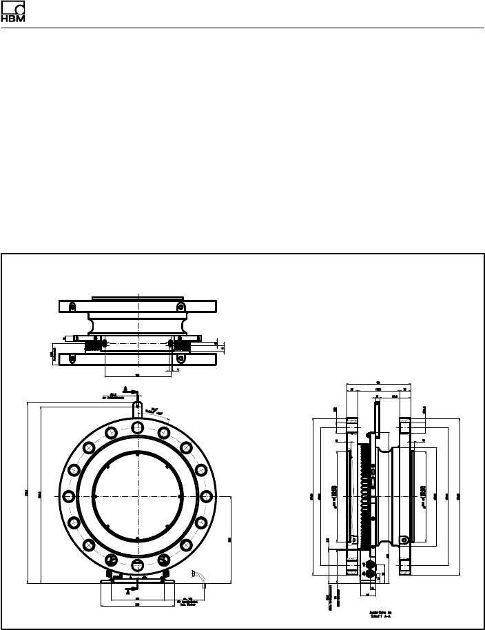
Abmessungen
T40FH A4429-1.0 HBM: public 63
13 Abmessungen
13.1 T40FH Drehmomentaufnehmer mit
Drehzahlmesssystem,
Option 4, Code SU2, DU2, HU2
13.1.1 T40FH 100kNm - 150kNm
Abmessungen in mm
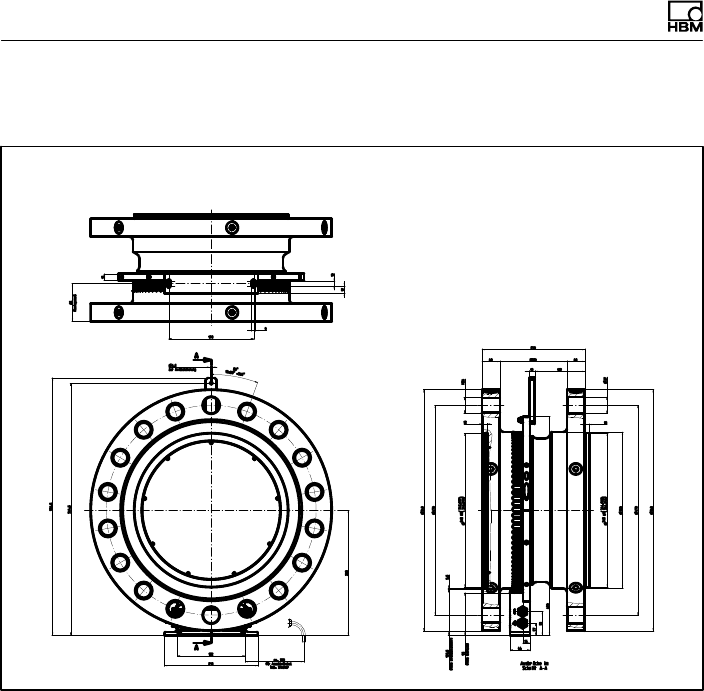
Abmessungen
64 A4429-1.0 HBM: public T40FH
13.1.2 T40FH 200kNm - 300kNm
Abmessungen in mm
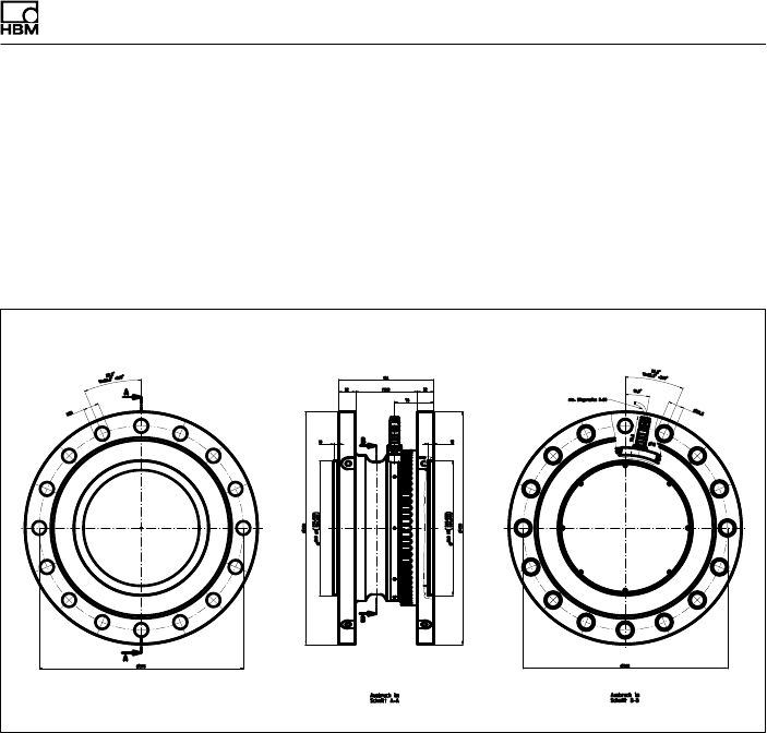
Abmessungen
T40FH A4429-1.0 HBM: public 65
13.2 T40FH Drehmomentaufnehmer
(nicht drehend),
Option 4, Code PNJ
13.2.1 T40FH 100 kNm - 150 kNm
Abmessungen in mm
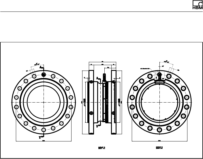
Abmessungen
66 A4429-1.0 HBM: public T40FH
13.2.2 T40FH 200kNm - 300kNm
Abmessungen in mm
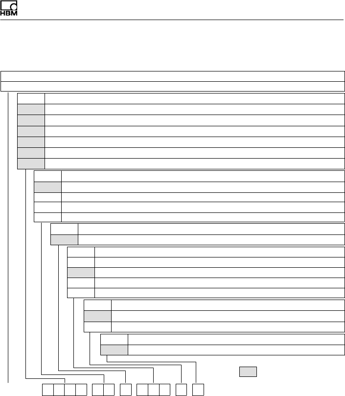
= VORZUGSTYPEN
Bestellnummern, Zubehör
T40FH A4429-1.0 HBM: public 67
14 Bestellnummern, Zubehör
Bestell‐Nr.
K-T40FH [nur mit Option 2 = MF/ST]
Code Option 1: Messbereich bis
100R 100 kN·m [nur mit Option 2 = MF/RO]
130R 130 kN·m [nur mit Option 2 = MF/RO]
150R 150 kN·m [nur mit Option 2 = MF/RO]
200R 200 kN·m [nur mit Option 2 = MF/RO]
250R 250 kN·m [nur mit Option 2 = MF/RO]
300R 300 kN·m [nur mit Option 2 = MF/RO]
Code Option 2: Komponente
MF Messflansch komplett
RO Rotor
ST Stator
NNicht rotierend
Code Option 3: Genauigkeit
SStandard (Linaritätsabweichung einschl. Hysterese ≤±0,1%)
Code Option 4: Elektrische Konfiguration [nur mit Option 2 = MF/ST]
SU2 Ausg.sign. 10 kHz ±5 kHz und ±10 V, Versorg.sp. 18…30V DC
DU2 Ausg.sign. 60 kHz ±30 kHz und ±10 V, Versorg.sp. 18…30V DC
HU2 Ausg.sign. 240 kHz ±120 kHz u. ±10 V, Versorg.sp. 18…30V DC
PNJ mV/V
Code Option 5: Drehzahlmesssystem
0Ohne Drehzahlmesssystem
1Magnetisches Drehzahlmesssystem
Code Option 6: Kundenspezifische Modifikation
SKeine kundenspezifische Modifikation
K-T40FH - 1 0 0 R - M F - S - D U 2 - 0 - S

Bestellnummern, Zubehör
68 A4429-1.0 HBM: public T40FH
Zubehör, zusätzlich zu beziehen
Artikel Bestell‐Nr.
Anschlusskabel für Drehmoment‐Ausgang
Anschlusskabel Drehmoment, 423 - D‐Sub 15P, 6m 1-KAB149-6
Anschlusskabel Drehmoment, 423 - freie Enden, 6m 1-KAB153-6
Anschlusskabel für Drehzahl‐Ausgang
Anschlusskabel Drehzahl, 423 - D‐Sub 15P, 6m 1-KAB150-6
Anschlusskabel Drehzahl, 423 - freie Enden, 6m 1-KAB154-6
Anschlusskabel Drehzahl mit Referenzimpuls, 423 8‐polig - D‐Sub
15P, 6m
1-KAB163-6
Anschlusskabel Drehzahl mit Referenzimpuls, 423 8‐polig - freie En
den, 6m
1-KAB164-6
Anschlusskabel TMC
Anschlusskabel TIM40/TMC, 6m 1-KAB174-6
Kabelbuchsen
423G-7S, 7‐polig (gerade) 3-3101.0247
423W-7S, 7‐polig (Winkel) 3-3312.0281
423G-8S, 8‐polig (gerade) 3-3312.0120
423W-8S, 8‐polig (Winkel) 3-3312.0282
Anschlusskabel, Meterware (Mindestbestellmenge: 10 m, Preis pro Meter)
Kab8/00-2/2/2 4-3301.0071

Technische Daten
T40FH A4429-1.0 HBM: public 69
15 Technische Daten
Genauigkeitsklasse 0.1
Drehmoment‐Messsystem (drehend)
Nenndrehmoment Mnom kNm 100 125 150 200 250 300
Nenndrehzahl min-1 3000 2000
Linearitätsabweichung einschließ
lich Hysterese,
bezogen auf den Nennkennwert
Frequenzausgang
Für ein max. Drehmoment im Bereich:
Zwischen 0% v. Mnom und 20% v.
Mnom
% ≤±0,03
> 20% v. Mnom und 60% v. Mnom % ≤±0,065
> 60% v. Mnom und 100% v. Mnom % ≤±0,1
Spannungsausgang
Für ein max. Drehmoment im Bereich:
Zwischen 0% v. Mnom und 20% v.
Mnom
% ≤±0,03
> 20% v. Mnom und 60% v. Mnom % ≤±0,065
> 60% v. Mnom und 100% v. Mnom % ≤±0,1
Rel. Standardabweichung der
Wiederholbarkeit,
nach DIN1319, bezogen auf die
Ausgangssignaländerung
Frequenzausgang % ≤±0,02
Spannungsausgang % ≤±0,02
Temperatureinfluss pro 10 K im
Nenntemperaturbereich
auf das Ausgangssignal, bezogen auf
den Istwert der Signalspanne
Frequenzausgang % ≤±0,1
Spannungsausgang % ≤±0,1

Technische Daten
70 A4429-1.0 HBM: public T40FH
Nenndrehmoment Mnom 300250200150125100kNm
auf das Nullsignal, bezogen auf den
Nennkennwert
Frequenzausgang % ≤±0,07
Spannungsausgang % ≤±0,07
Nennkennwert
(Spanne zwischen Dreh
moment = Null und Nenndrehmoment)
Frequenzausgang 10kHz / 60kHz /
240kHz
kHz 5/30/120
Spannungsausgang V 10
Kennwerttoleranz
(Abweichung der tatsächlichen Aus
gangsgröße bei Mnom vom Nennkenn
wert)
Frequenzausgang % ±0,1
Spannungsausgang % ±0,1
Ausgangssignal bei
Drehmoment = Null
Frequenzausgang kHz 10/60/240
Spannungsausgang V 0
Nennausgangssignal
Frequenzausgang
bei positivem Nenndrehmoment kHz 15 1) / 90 2) / 360 3)
(5 V symmetrisch 4))
bei negativem Nenndrehmoment kHz 5 1) / 30 2) / 120 3)
(5 V symmetrisch 4))
Spannungsausgang
bei positivem Nenndrehmoment V +10
bei negativem Nenndrehmoment V -10
Lastwiderstand
Frequenzausgang kΩ≥2
Spannungsausgang kΩ ≥10

Technische Daten
T40FH A4429-1.0 HBM: public 71
Nenndrehmoment Mnom 300250200150125100kNm
Langzeitdrift über 48h bei Refe
renztemperatur
Frequenzausgang % ≤±0,03
Spannungsausgang % ≤±0,03
Messfrequenzbereich, -3dB kHz 11) / 32) / 63)
Gruppenlaufzeit μst4001) / t2202) / t1503)
Restwelligkeit
Spannungsausgang 5) mV t40
Maximaler Aussteuerbereich 6)
Frequenzausgang kHz 2,5 … 17,5 1) / 15 … 105 2) /
60 … 420 3)
Spannungsausgang V -12 … +12
Energieversorgung
Nennversorgungsspannung
(Schutzkleinspannung DC)
V18 … 30
Stromaufnahme im Messbetrieb A< 1
Stromaufnahme im Anlaufbetrieb A< 4 (typ. 2) 50 μs
Nennaufnahmeleistung W < 10
Maximale Kabellänge m 50
Shuntsignal ca. 50 % von Mnom
Toleranz des Shuntsignals, bezo
gen auf Mnom
% <±0,05
Nennauslösespannung V 5
Grenzauslösespannung V 36
Shuntsignal ein Vmin. >2,5
Shuntsignal aus Vmax. <0,7
Drehmoment-Messsystem (nicht drehend)
Genauigkeitsklasse 0.1

Technische Daten
72 A4429-1.0 HBM: public T40FH
Nenndrehmoment Mnom 300250200150125100kNm
Nennkennwert (Nennsignalspanne
zwischen Drehmoment = Null und
Nenndrehmoment)
mV/V 0,63…..1,1 (Der Kennwert ist auf
dem Typenschild angegeben)
Linearitätsabweichung einschl.
Hysterese, bezogen auf den Nenn
kennwert (Spannungsausgang)
Für ein max. Drehmoment im Bereich:
Zwischen 0% v. Mnom und
20% v. Mnom
%≤± 0,03
> 20% v. Mnom und 60% v. Mnom %≤± 0,065
> 60% v. Mnom und 100% v. Mnom %≤± 0,1
Temperatureinfluss pro 10 K im
Nenntemperaturbereich
auf das Ausgangssignal, bezogen auf
den Istwert der Signalspanne
%<± 0,1
auf das Nullsignal, bezogen auf den
Nennkennwert
%≤± 0,07
Relative Standardabweichung der
Reproduzierbarkeit (Veränderlich
keit) nach DIN 1319, bezogen auf die
Ausgangssignaländerung.
%≤± 0,02
Eingangswiderstand bei Referenz
temperatur
Ω1560 ± 100
Ausgangswiderstand bei Referenz
temperatur
Ω1400 ± 100
Referenzspeisespannung V 5
Gebrauchsbereich der Speisespannung 2,5 … 12
Aufnehmer-Identifikation TEDS nach IEEE 1451.4
Drehzahl‐Messsystem
Messsystem Drehzahl Magnetische Abtastung und
Zahnkranz
Ausgangssignale 2 Rechtecksignale um 90° pha
senverschoben, 5V TTL/RS-422

Technische Daten
T40FH A4429-1.0 HBM: public 73
Nenndrehmoment Mnom 300250200150125100kNm
Anzahl der Impulse pro Umdrehung
(Zähnezahl)
72 86
Ausgangssignalpegel High V ≥3,5
Ausgangssignalpegel Low V ≤0,8
Maximal zulässige Ausgangs
frequenz
kHz 25
Radialer Nennabstand zwischen
Sensorkopf und den Zähnen
mm 2,5
Radialer Arbeitsbereich mm 1,5 – 3,5
Zulässiger axialer Verschiebeweg mm ±2
Zulässige magnetische Feldstärke
für Signalabweichungen
kA/m <0,1
Allgemeine Angaben
EMV
Emission (nach FCC 47, Teil 15,
Unterabteilung C)7)
Emission
(nach EN61326‐1, Abschnitt 7)
Funkstörfeldstärke Klasse B
Störfestigkeit (EN61326‐1, Tab. 2)
Elektromagnetisches Feld (AM) V/m 10
Magnetisches Feld A/m 100
Elektrostatische Entladungen (ESD)
Kontaktentladung kV 4
Luftentladung kV 8
Schnelle Transienten (Burst) kV 1
Stoßspannungen (Surge) kV 1
Leitungsgebundene Störungen (AM) V 10
Schutzart nach EN60529 IP 54
Referenztemperatur °C23

Technische Daten
74 A4429-1.0 HBM: public T40FH
Nenndrehmoment Mnom 300250200150125100kNm
Nenntemperaturbereich °C+10 … +70
Gebrauchstemperaturbereich 8) °C-20 … +85
Lagerungstemperaturbereich °C-40 … +85
Mechanischer Schock nach
EN60068‐2‐279)
Anzahl n 1000
Dauer ms 3
Beschleunigung (Halbsinus) m/s2650
Schwingbeanspruchung in drei
Richtungen nach EN60068‐2‐6 9)
Frequenzbereich Hz 10 … 2000
Dauer h 2,5
Beschleunigung (Amplitude) m/s2100
Belastungsgrenzen 10)
Grenzdrehmoment, bez. auf Mnom11) kNm 200 400
Bruchdrehmoment, bez. auf Mnom11) kNm >300 >600
Grenzlängskraft 12) kN 230 290
Grenzquerkraft 12) kN 110 240
Grenzbiegemoment 12) N⋅m 22 35
Schwingbreite nach DIN50100
(Spitze/Spitze) 13) kNm 200 400
Oberes maximales Drehmoment kNm 150 300
Unteres maximales Drehmoment kNm -150 -300
Mechanische Werte
Baugröße BG1 BG2
Drehsteifigkeit cTkN⋅m/rad 119310 228090
Verdrehwinkel bei Mnom Grad 0,072 0,075
Steifigkeit in axialer Richtung cakN/mm 1855 3900
Steifigkeit in radialer Richtung crkN/mm 3340 4910

Technische Daten
T40FH A4429-1.0 HBM: public 75
Nenndrehmoment Mnom 300250200150125100kNm
Steifigkeit bei Biegemoment um
eine radiale Achse cb
kN⋅m/rad 25495 65900
kN⋅m/
Grad
445 1150
Maximale Auslenkung bei
Grenzlängskraft
mm 0,1
Zusätzlicher maximaler
Rundlauffehler bei Grenzquerkraft
mm 0,1
Zusätzliche maximale Plan
parallelitätsabweichung bei
Grenzbiegemoment
mm 0,5
Auswucht‐Gütestufe nach
DIN ISO 1940
G 6,3
Zul. max. Schwingweg des
Rotors14) (Spitze-Spitze)
Wellenschwingungen im Bereich der
Anschlussflansche in Anlehnung an
ISO7919‐3
Normalbetrieb (Dauerbetrieb) μm s(p*p)+9000
n
Ǹ(n in min-1)
Start‐ und Stoppbetrieb/Resonanz
bereiche (temporär)
μm s(p*p)+13200
n
Ǹ(n in min-1)
Massenträgheitsmoment des
Rotors Iv
(um Drehachse ohne Berücksichti
gung der Flanschschrauben)
kg⋅m22,0 5,15
Anteiliges Massenträgheitsmoment
für Übertragerseite (Seite des
Flanschs mit Außenzentrierung)
% v. Iv45 47
Zulässige max. statische
Exzentrizität des Rotors (radial) zum
Statormittelpunkt
ohne Drehzahlmodul mm ±2
mit Drehzahlmodul mm ±1

Technische Daten
76 A4429-1.0 HBM: public T40FH
Nenndrehmoment Mnom 300250200150125100kNm
Zulässiger axialer Verschiebeweg15)
zwischen Rotor und Stator
mm ±2
Gewicht
Rotor kg 78 142
Stator kg 2,1 2,3
1) Option 5, 10 ±5 kHz (Code SU2)
2) Option 5, 60 ±30 kHz (Code DU2)
3) Option 5, 240 ±120 kHz (Code HU2)
4) Komplementäre Signale RS‐422, Abschlusswiderstand beachten.
5) Signalfrequenzbereich 0,1 bis 10kHz
6) Ausgangssignalbereich, in dem ein wiederholbarer Zusammenhang zwischen Drehmoment und
Ausgangssignal besteht.
7) Gilt nur für rotierende Ausführung
8) Ab 70°C ist eine Wärmeableitung über die Bodenplatte des Stators erforderlich. Die Temperatur
der Bodenplatte darf 85°C nicht überschreiten.
9) Fixierung von Antennenring und Anschlussstecker erforderlich.
10) Jede irreguläre Beanspruchung (Biegemoment, Quer‐ oder Längskraft, Überschreiten des
Nenndrehmoments) ist bis zu der angegebenen Belastungsgrenze nur dann zulässig, solange
keine der jeweils anderen von ihnen auftreten kann. Andernfalls sind die Grenzwerte zu
reduzieren. Wenn je 30 % des Grenzbiegemoments und der Grenzquerkraft vorkommen, sind
nur noch 40 % der Grenzlängskraft zulässig, wobei das Nenndrehmoment nicht überschritten
werden darf. Die Auswirkungen der zulässigen Biegemomente, Längs‐ und Querkräfte auf das
Messergebnis sind v±0,3% (50Nm: ≤±0,6%) des Nenndrehmomentes. Die Belastungsgrenzen
gelten nur für den Nenntemperaturbereich. Bei Temperaturen <10_C sind die
Belastungsgrenzen um ca. 30% zu reduzieren (Zähigkeitsreduzierung).
11) Bei statischer Belastung.
12) Statisch und dynamisch.
13) Das Nenndrehmoment darf nicht überschritten werden.
14) Beeinflussung der Schwingungsmessungen durch Rundlauffehler, Schlag, Formfehler, Kerben,
Riefen, örtlichen Restmagnetismus, Gefügeunterschiede oder Werkstoffanomalien sind zu
berücksichtigen und von der eigentlichen Wellenschwingung zu trennen.
15) Oberhalb des Nenntemperaturbereiches: ±1,5mm.
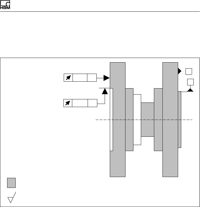
Ergänzende technische Informationen
T40FH A4429-1.0 HBM: public 77
16 Ergänzende technische Informationen
Plan‐ und Rundlauftoleranzen
Innenzentrierung
A
0,02 AB
B
0,02 AB
Flansch A Flansch B
Härte 46 ... 54 HRC
Oberflächengüte der Plan‐ und Rundlaufflächen (A, B und AB)
0,8
Um die Eigenschaften des Drehmoment‐Messflanschs im
eingebauten Zustand zu erhalten, empfehlen wir, die
angegebenen Form‐ und Lagetoleranzen, die Ober
flächengüte und Härte auch für die kundenseitigen An
schlüsse zu wählen.

www.hbm.com
HBM Test and Measurement
Tel. +49 6151 803-0
Fax +49 6151 803-9100
info@hbm.com
measure and predict with confidence
A4429-1.0 7-2002.4429 HBM: public