Hottinger Bruel and Kjaer T40S2TOS6 T40-S2TOS6 Torquemeter User Manual A3452 T40B
Hottinger Baldwin Messtechnik GmbH T40-S2TOS6 Torquemeter A3452 T40B
User Manual
Mounting Instructions | Montageanleitung
English Deutsch
T40B
Hottinger Baldwin Messtechnik GmbH
Im Tiefen See 45
D-64239 Darmstadt
Tel. +49 6151 803-0
Fax +49 6151 803-9100
Email: info@hbm.com
Internet: www.hbm.com
Mat.: 7-2002.3452
DVS: A3452-10.0
11.2014
E Hottinger Baldwin Messtechnik GmbH.
Subject to modifications.
All product descriptions are for general information only.
They are not to be understood as a guarantee of quality or
durability.
Änderungen vorbehalten.
Alle Angaben beschreiben unsere Produkte in allgemeiner
Form. Sie stellen keine Beschaffenheits- oder Haltbarkeits
garantie im Sinne des §443 BGB dar.

Mounting Instructions | Montageanleitung
English Deutsch
T40B

2 A3452-10.0 T40B
English
1 Safety instructions 4........................................
2 Markings used 12............................................
2.1 Symbols on the transducer 12..................................
2.2 The markings used in this document 12..........................
3 Application 14...............................................
4 Structure and mode of operation 15...........................
5 Mechanical installation 21....................................
5.1 Important precautions during installation 21......................
5.2 Conditions on site 22..........................................
5.3 Installation orientation 23......................................
5.4 Installation options 23.........................................
5.4.1 Installation without dismantling the antenna ring, Option 7, Code U with
antenna shielding cover 24.....................................
5.4.2 Installation with subsequent stator mounting, Option 7, Code S 25...
5.5 Installing the rotor 26..........................................
5.6 Installing the stator 29.........................................
5.7 Rotational speed measuring system, reference signal (optional) 37..
6 Electrical connection 39......................................
6.1 General information 39........................................
6.2 EMC protection 39............................................
6.3 Connector pin assignment 41...................................
6.4 Supply voltage 47.............................................
7 Shunt signal 49..............................................
8 Functionality testing 50......................................
8.1 Rotor status, LED A (upper LED) 51.............................
8.2 Stator status, LED B (lower LED) 52............................

T40B A3452-10.0 3
9 Load‐carrying capacity 53....................................
10 Maintenance 54..............................................
11 Waste disposal and environmental protection 55..............
12 Ordering numbers, accessories 56............................
13 Specifications 58............................................
13.1 Nominal (rated) torque 50N·m to 500N·m 58....................
13.2 Nominal (rated) torque 1kN·m to 10kN·m 66.....................
14 Supplementary technical information 76......................
Safety instructions
4 A3452-10.0 T40B
1 Safety instructions
FCC Compliance & Advisory Statement for Option 7,
Code U
Important
Any changes or modification not expressly approved in
writing by by the party responsible for compliance could
void the user’s authority to operate the device. Where
specified additional components or accessories else
where defined to be used with the installation of the prod
uct, they must be used in order to ensure compliance
with FCC regulations.
This device complies with Part 15 of the FCC Rules.
Operation is subject to the following two conditions: (1)
this device may not cause harmful interference, and (2)
this device must accept any interference received, includ
ing interference that may cause undesired operation.
The FCC identifier or the unique identifier, as appropri
ate, must be displayed on the device.
Model Measuring range FCC ID IC
T40S2TOS6
50 Nm, 100 Nm,
200 Nm
2ADAT−T40S2TOS6 12438A−T40S2TOS6
500 Nm, 1 kNm
2 kNm, 3 kNm
5 kNm
10 kNm
Safety instructions
T40B A3452-10.0 5
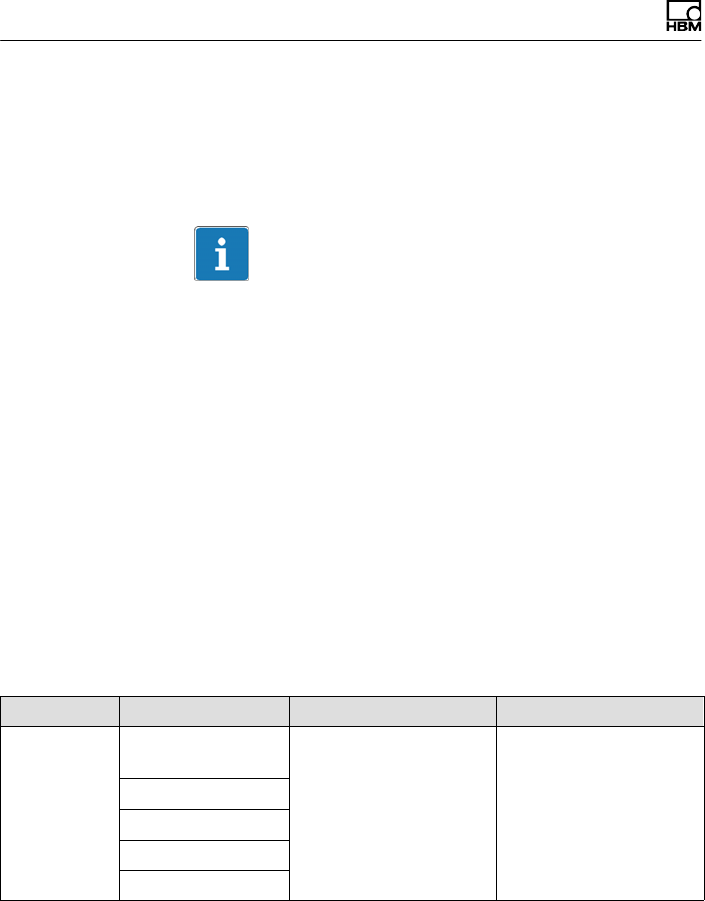
Label example with FCC ID and IC number.
Model: T40S2TOS6
FCC ID: 2ADAT-T40S2TOS6
IC: 12438AT40S2TOS6
This device complies with part 15 of the FCC Rules. Opera
tion is subject to the following two conditions: (1) This device
may not cause harmful interference, and (2) this device must
accept any interference received, including interference that
may cause undesired operation.
Label
Fig. 1.1 Location of the label on the stator of the device
Model: T40S2TOS6
FCC ID: 2ADAT-T40S2TOS6
IC: 12438AT40S2TOS6
This device complies with part 15 of the FCC Rules. Operation is
subject to the following two conditions: (1) This device may not
cause harmful interference, and (2) this device must accept any
interference received, including interference that may cause
undesired operation.
Fig. 1.2 Example of the label

Safety instructions
6 A3452-10.0 T40B
Industry Canada for Option 7, Code U
Darmstadt, 2014-11-13
This product has not yet received IC (Industry Canada)
approval. The certification process for this product is still
under way. HBM currently expects that IC approval will
be granted by the end of December 2014.
Your local HBM contact looks forward to answer any
questions you may have regarding IC approval.
Darmstadt, le 13 novembre 2014
Ce produit n'a pas encore obtenu l'approbation IC (Indus
trie Canada). Le produit est encore en processus de
certification. Actuellement, HBM suppose que l'appro
bation IC sera accordée jusqu'à fin décembre 2014.
Si vous avez des questions au sujet de l'approbation IC,
veuillez vous adresser à votre représentation HBM sur
place.
This device complies with Industry Canada standard
RSS210.
This device complies with Industry Canada
license−exempt RSS standard(s).Operation is subject to
the following two conditions: (1) this device may not
cause interference, and (2) this device must accept any
interference, including interference that may cause unde
sired operation of the device.
Cet appareil est conforme aux norme RSS210 d’Industrie
Canada.
Cet appareil est conforme aux normes d’exemption de
licence RSS d’Industry Canada. Son fonctionnement est
soumis aux deux conditions suivantes : (1)cet appareil ne
doit pas causer d’interférence et (2) cet appareil doit

Safety instructions
T40B A3452-10.0 7
accepter toute interférence, notamment les interférences
qui peuvent affecter son fonctionnement.
Appropriate use
The T40B torque flange is used exclusively for torque,
angle of rotation and power measurement tasks within
the load limits stipulated in the specifications. Any other
use is not appropriate.
Stator operation is only permitted when the rotor is
installed.
The torque flange may only be installed by qualified per
sonnel in compliance with the specifications and with the
safety requirements and regulations of these mounting
instructions. It is also essential to observe the applicable
legal and safety regulations for the application con
cerned. The same applies to the use of accessories.
The torque flange is not intended for use as a safety
component. Please also refer to the “Additional safety
precautions" section. Proper and safe operation requires
proper transportation, correct storage, siting and mount
ing, and careful operation.
Load carrying capacity limits
The data in the technical data sheets must be complied
with when using the torque flange. In particular, the
respective maximum loads specified must never be
exceeded. For example, the values stated in the specifi
cations must not be exceeded for
Slimit torque,
Slongitudinal limit force, lateral limit force or limit bend
ing moment,
Storque oscillation width,

Safety instructions
8 A3452-10.0 T40B
Sbreaking torque,
Stemperature limits,
Sthe limits of the electrical load‐carrying capacity.
Use as a machine element
The torque flange can be used as a machine element.
When used in this manner, it must be noted that, to favor
greater sensitivity, the transducer is not designed with
the safety factors usual in mechanical engineering.
Please refer here to the section “Load carrying capacity
limits" and to the specifications.
Accident prevention
According to the prevailing accident prevention regula
tions, once the transducers have been mounted, a cover
ing agent or cladding has to be fitted as follows:
SThe covering agent or cladding must not be free to
rotate.
SThe covering agent or cladding should prevent
squeezing or shearing and provide protection against
parts that might come loose.
SCovering agents and cladding must be positioned at a
suitable distance or be so arranged that there is no
access to any moving parts within.
SCovering agents and cladding must still be attached
even if the moving parts of the torque flange are
installed outside people's movement and working
range.
The only permitted exceptions to the above requirements
are if the torque flange is already fully protected by the
design of the machine or by existing safety precautions.

Safety instructions
T40B A3452-10.0 9
Additional safety precautions
The torque flange cannot (as a passive transducer)
implement any (safety‐relevant) cutoffs. This requires
additional components and constructive measures, for
which the installer and operator of the plant is responsi
ble. The electronics conditioning the measurement signal
should be designed so that measurement signal failure
does not subsequently cause damage.
The scope of supply and performance of the transducer
covers only a small area of torque measurement technol
ogy. In addition, equipment planners, installers and oper
ators should plan, implement and respond to safety engi
neering considerations in such a way as to minimize
residual dangers. Pertinent national and local regulations
must be complied with.
General dangers of failing to follow the safety
instructions
The torque flange corresponds to the state of the art and
is reliable. Transducers can give rise to residual dangers
if they are incorrectly operated or inappropriately
mounted, installed and operated by untrained personnel.
Every person involved with siting, starting‐up, operating
or repairing a torque flange must have read and under
stood the mounting instructions and in particular the tech
nical safety instructions. The transducers can be dam
aged or destroyed by non‐designated use of the
transducer or by non‐compliance with the mounting and
operating instructions, these safety instructions or any
other applicable safety regulations (BG safety and acci
dent prevention regulations), when using the transducers.
Transducers can break, particularly in the case of over
loading. The breakage of a transducer can also cause
damage to property or injury to persons in the vicinity of
the transducer.

Safety instructions
10 A3452-10.0 T40B
If the torque flange is not used according to the desig
nated use, or if the safety instructions or specifications in
the mounting and operating instructions are ignored, it is
also possible that the transducer may fail or malfunction,
with the result that persons or property may be adversely
affected (due to the torques acting on or being monitored
by the torque flange).
Conversions and modifications
The transducer must not be modified from the design or
safety engineering point of view except with our express
agreement. Any modification shall exclude all liability on
our part for any damage resulting therefrom.
Selling on
If the torque flange is sold on, these mounting instruc
tions must be included with the torque flange.
Qualified personnel
Qualified personnel means persons entrusted with siting,
mounting, starting up and operating the product, who
possess the appropriate qualifications for their function.
This includes people who meet at least one of the three
following requirements:
1. Knowledge of the safety concepts of automation tech
nology is a requirement and as project personnel, you
must be familiar with these concepts.
2. As automation plant operating personnel, you have
been instructed how to handle the machinery. You are
familiar with the operation of the equipment and tech
nologies described in this documentation.
3. As system startup engineers or service engineers,
you have successfully completed the training to qual

Safety instructions
T40B A3452-10.0 11
ify you to repair the automation systems. You are also
authorized to ground and label circuits and equipment
and place them in operation in accordance with safety
engineering standards.
Markings used
12 A3452-10.0 T40B
2 Markings used
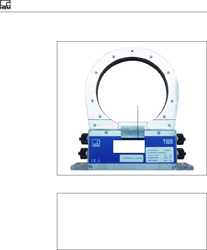
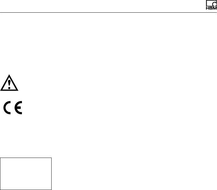
2.1 Symbols on the transducer
Read and note the data in this manual
CE mark
The CE mark enables the manufacturer to guarantee that
the product complies with the requirements of the rele
vant EC directives (the Declaration of Conformity can be
found on the HBM website at www.hbm.com under
HBMdoc).
Label example
Label example with FCC ID and IC number, Option 7
Code U. Location of the label on the stator device.
2.2 The markings used in this document
Important instructions for your safety are specifically
identified. It is essential to follow these instructions in
order to prevent accidents and damage to property.
Model: T40S2TOS6
FCC ID: 2ADAT-T40S2TOS6
IC: 12438AT40S2TOS6
This device complies with part 15 of the
FCC Rules. Operation is subject to the
following two conditions: (1) This device
may not cause harmful interference, and
(2) this device must accept any interfer
ence received, including interference
that may cause undesired operation.
Markings used
T40B A3452-10.0 13
Symbol Significance
WARNING This marking warns of a potentially dangerous
situation in which failure to comply with safety
requirements can result in death or serious physical
injury.
CAUTION This marking warns of a potentially dangerous
situation in which failure to comply with safety
requirements can result in slight or moderate physical
injury.
Note This marking draws your attention to a situation in
which failure to comply with safety requirements can
lead to damage to property.
Important
This marking draws your attention to important
information about the product or about handling the
product.
Tip
This marking indicates application tips or other
information that is useful to you.
Information
This marking draws your attention to information
about the product or about handling the product.
Emphasis
See….
Italics are used to emphasize and highlight text and
references to other chapters and external documents.

Application
14 A3452-10.0 T40B
3 Application
The T40B torque flange measures static and dynamic
torques on stationary and rotating shafts. Test beds can
be extremely compact because of the compact design of
the transducer. This offers a very wide range of applica
tions.
The T40B torque flange is reliably protected against elec
tromagnetic interference. It has been tested according to
harmonized European standards and/or complies with
US and Canadian standards. The product carries the
CE mark and/or FCC label.

Structure and mode of operation
T40B A3452-10.0 15
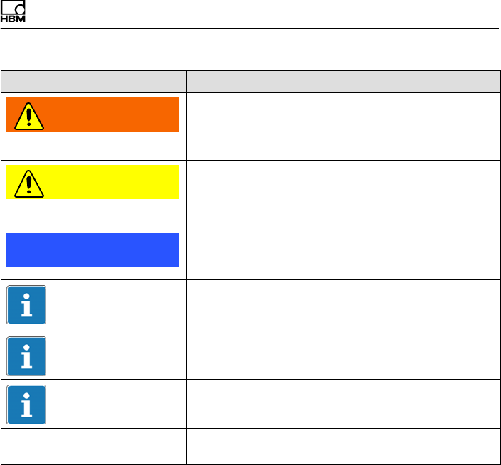
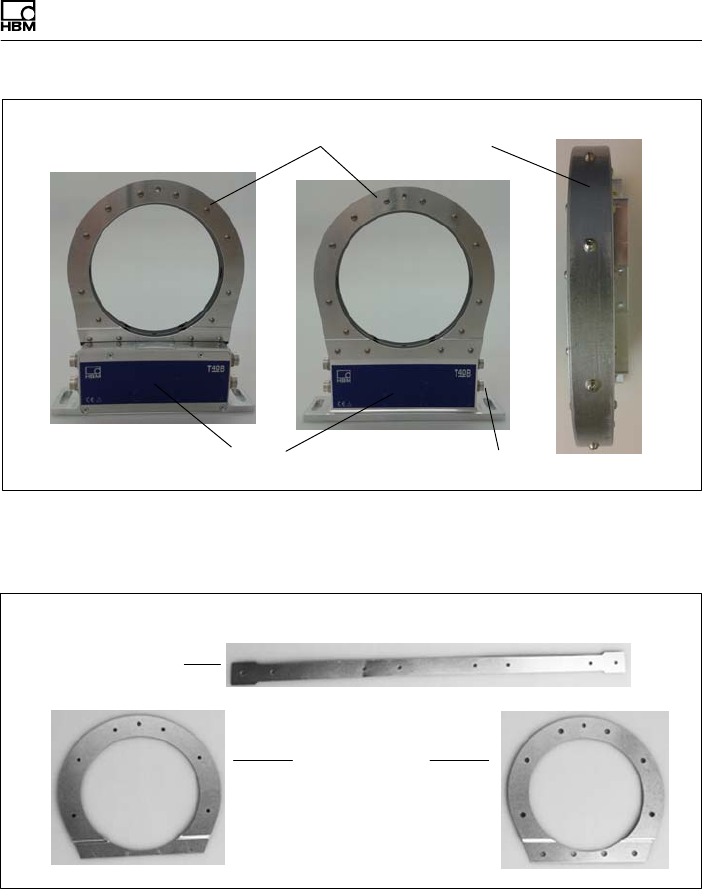
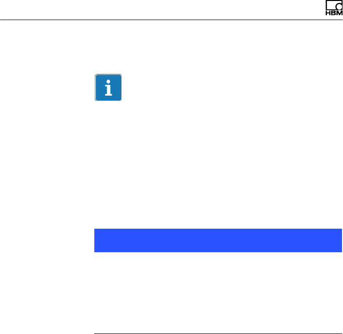
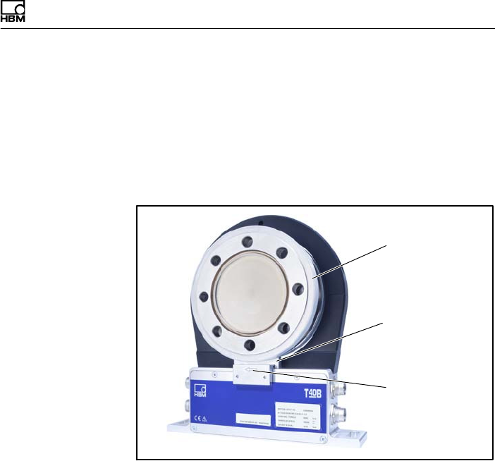
4 Structure and mode of operation
The torque flange consists of two separate parts: the
rotor and the stator. The rotor comprises the measuring
body and the signal transmission elements.
Strain gages (SGs) are installed on the measuring body.
The rotor electronics for transmitting the bridge excitation
voltage and the measurement signal are located centrally
in the flange. The transmitter coils for contactless trans
mission of excitation voltage and measurement signal are
located on the measuring body's outer circumference.
The signals are sent and received by a separable
antenna ring. Separable antenna ring not for Option 7,
Code U. The antenna ring is mounted on a housing that
contains the electronics for voltage adaptation and the
signal conditioning.
Connector plugs for the torque and rotational speed sig
nals, the voltage supply and digital output, are located on
the stator. The antenna segments (the antenna ring)
must be mounted concentrically around the rotor (see
chapter 5).
Structure and mode of operation
16 A3452-10.0 T40B
Antenna
segments
Rotor
Connect
or plugs
Stator
housing
Type plate
Connect
or plugs
Fig. 4.1 Mechanical construction without a rotational speed
measuring system, Option 7, Code S
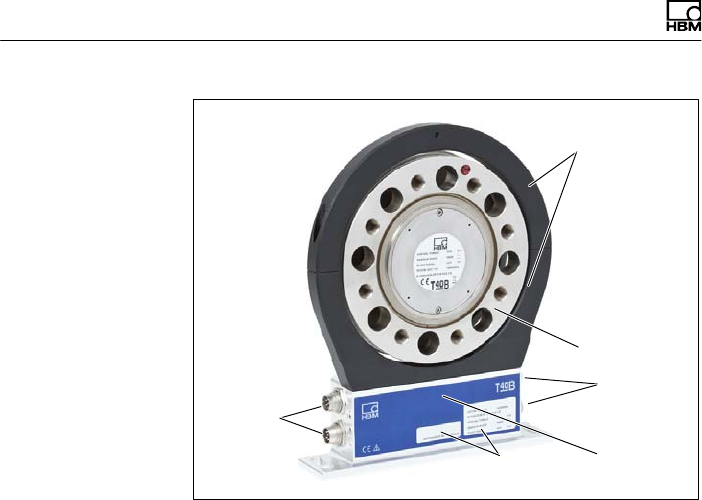
The rotational speed sensor is mounted on the stator in
Option 6 with a rotational speed measuring system. The
rotational speed is measured magnetically via an AMR
sensor and a magnetic ring. The magnetic ring for mea
suring the rotational speed is welded to the flange.
Structure and mode of operation
T40B A3452-10.0 17
Antenna segments
Rotor
Connector
plugs
Stator housing
Type plate
Connector plugs
Sensor head for measuring
rotational speed
Magnetic ring for rotational
speed measurement
Fig. 4.2 Mechanical construction with a rotational speed
measuring system, Option 7, Code S
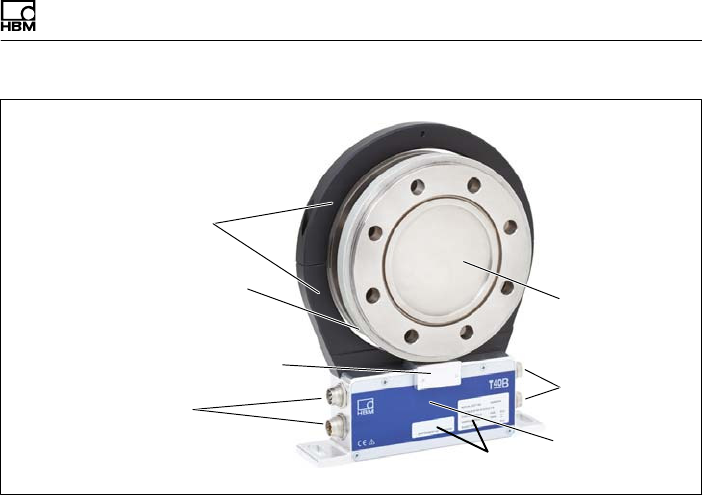
In the version with a rotational speed measuring system,
the transducer can also be fitted with a sensor head for a
reference signal (zero index) for measuring the angle of
rotation. The magnet to be used for this is located on the
inner surface of the flange. The sensor head for sampling
the reference signal is located in the bracket above the
rotational speed sensor.
Structure and mode of operation
18 A3452-10.0 T40B
Antenna segments
Rotor
Connector
plugs
Stator housing
Type plate
Connector plugs
Sensor head for
measuring
rotational speed
Magnetic ring for rotational
speed measurement
Sensor head for the
reference signal
Fig. 4.3 Mechanical construction with rotational speed
measuring system and sensor for the reference
signal (zero index), Option 7, Code S
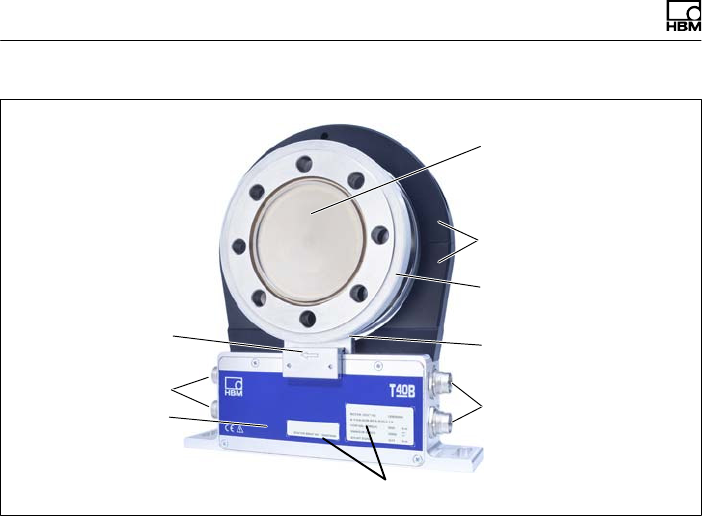
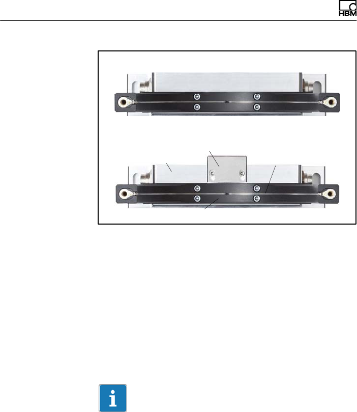
Structure and mode of operation
T40B A3452-10.0 19
Stator housing
Antenna segments with mounted shielding plates
Connector plugs
Fig. 4.4 Mechanical construction of Stator with mounted
shielding plates without rotational speed Option 7,
Code U
Dismounted shielding plates
Axial shielding
plates
Radial shielding
plate
Fig. 4.5 Individual shielding plates, Option 7, Code U
Structure and mode of operation
20 A3452-10.0 T40B
Information
Mechanical construction with rotational speed measuring
System is the same as in Fig. 4.2 with additional shield
ing plate of antenna ring see Fig. 4.4.
Important
The use of the shielding plates are important to ensure
compliance with FCCregulations. If the shielding plates
has to be removed for any purpose (e.g. in-stallation or
maintenance), they must be replaced in the original posi
tion be-fore the product is used.

Mechanical installation
T40B A3452-10.0 21
5 Mechanical installation
5.1 Important precautions during
installation
Note
A torque flange is a precision measuring element and
therefore needs careful handling. Dropping or knocking
the transducer may cause permanent damage. Make
sure that the transducer cannot be overloaded, including
while it is being mounted.
SHandle the transducer with care.
SCheck the effect of bending moments, critical rota
tional speeds and natural torsional vibrations, to pre
vent the transducer being overloaded by resonance
sharpness.
SMake sure that the transducer cannot be overloaded.
WARNING
There is a danger of the transducer breaking if it is over
loaded. This can cause danger for the operating person
nel of the system in which the transducer is installed.
Implement appropriate safety measures to avoid over
loads and to protect against resulting dangers.
SUse a threadlocker (medium strength, e.g. LOCTITE)
to glue the screws into the counter thread to exclude

Mechanical installation
22 A3452-10.0 T40B
prestressing loss due to screw slackening, in the
event of alternating loads.
SComply with the mounting dimensions to enable cor
rect operation.
An appropriate shaft flange enables the T40B torque
flange to be mounted directly. It is also possible to mount
a joint shaft or relevant compensating element directly on
the rotor (using an intermediate flange when required).
Under no circumstances should the permissible limits
specified for bending moments, lateral and longitudinal
forces be exceeded. Due to the T40B torque flange's
high torsional stiffness, dynamic shaft train changes are
kept to a minimum.
Important
Even if the unit is installed correctly, the zero point
adjustment made at the factory can shift by up to
approx. 2% of the sensitivity. If this value is exceeded,
we advise you to check the mounting conditions. If the
residual zero offset when the unit is removed is greater
than 1% of the sensitivity, please send the transducer
back to the Darmstadt factory for testing.
5.2 Conditions on site
The T40B torque flange must be protected against
coarse dirt particles, dust, oil, solvents and moisture.
There is wide ranging compensation for the effects of
temperature on the output and zero signals of the trans
ducer (see “Specifications" section). If there are no static
temperature ratios, for example, because of the tempera
ture differences between the measuring body and the

Mechanical installation
T40B A3452-10.0 23
flange, the values given in the specifications can be
exceeded. In this case, ensure static temperature ratios
by cooling or heating, depending on the application. As
an alternative, check if thermal decoupling is possible,
e.g. by means of heat radiating elements such as multi
ple disc couplings.
5.3 Installation orientation
The torque flange can be installed with any orientation.
With clockwise torque, the output frequency is 60 to
90 kHz for Option 5, Code DU2 (Option 5, Code SU2: 10
to 15 kHz; Option HU2: 240 to 360kHz). In conjunction
with HBM amplifiers or when using the voltage output, a
positive output signal (0 V to +10 V) is present. In the
case of the rotational speed measuring system, an arrow
is attached to the stator housing to clearly define the
direction of rotation: if the measurement flange turns in
the direction of the arrow, connected HBM measuring
amplifiers deliver a positive output signal.
5.4 Installation options
There are basically two options for mounting the torque
flange: with or without dismantling the antenna ring. We
recommend mounting as described in Chapter 5.4.1. If
mounting in accordance with Chapter 5.4.1 is not possi
ble, (e.g. in the case of subsequent stator replacement),
you will have to dismantle the antenna ring (only possible
for Option 7, Code S). It is essential in this case to com
ply with the notes on assembling the antenna segments
(see Chapter 5.4.2).
Mechanical installation
24 A3452-10.0 T40B
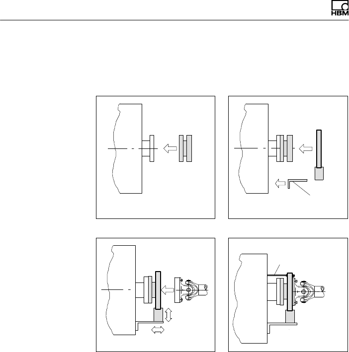
5.4.1 Installation without dismantling the antenna
ring, Option 7, Code U with antenna shielding
cover
Mounting supplied
by customer
1. Install rotor 2. Install stator
3. Finish shaft train installation 4. Fit support
Support supplied
by customer
Mechanical installation
T40B A3452-10.0 25
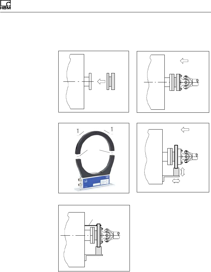
5.4.2 Installation with subsequent stator mounting,
Option 7, Code S
Fan‐type
lock
washers
Washers
1. Install rotor 2. Install shaft train
3. Dismantle antenna segment 4. Install antenna segment
Support supplied
by customer
5. Fit support
Mechanical installation
26 A3452-10.0 T40B
5.5 Installing the rotor
Tip
Usually the rotor type plate is no longer visible after
installation. This is why we include with the rotor addi
tional stickers with the important characteristics, which
you can attach to the stator or any other relevant
test‐bench components. You can then refer to them
whenever there is anything you wish to know, such as
the shunt signal. To explicitly assign the data, the identifi
cation number and the size are engraved on the rotor
flange, where they can be seen from outside.
Note
Make sure during installation that you do not damage the
measuring zone marked in Fig. 5.1 by using it to support
tools, or knocking tools against it when tightening screws,
for example. This can damage the transducer and pro
duce measurement errors, or even destroy the trans
ducer.
Mechanical installation
T40B A3452-10.0 27
without rotational speed
measuring system
with rotational
speed measuring
system
Flange plane faces
Transmitter winding Rotational speed measuring system
Measuring
zone
Fig. 5.1 Bolted rotor connection
1. Prior to installation, clean the plane faces of the trans
ducer flange and the counter flange.
For safe torque transfer, the faces must be clean and
free from grease. Use a piece of cloth or paper
soaked in solvent. When cleaning, make sure that you
do not damage the transmitter winding or the rota
tional speed measuring system.
2. For the bolted rotor connection (see Fig. 5.1), use six
or eight DIN EN ISO 4762 hexagon socket screws of
the property class stated in Tab. 5.1, in a suitable
length (dependent on the connection geometry, see
Tab. 5.1 on page 29).
We recommend DIN EN ISO 4762 socket head cap
screws, blackened, smooth‐headed, permitted size
and shape variance in accordance with DIN
ISO 4759, Part 1, product class A.

Mechanical installation
28 A3452-10.0 T40B
3. Fasten all screws with the specified torque (Tab. 5.1
on page 29).
4. There are six or eight tapped holes on the rotor for
continuing the shaft train mounting. Again use screws
of property class 10.9 or 12.9 and tighten them with
the prescribed torque, as specified in Tab. 5.1.
Important
Use a threadlocker (medium strength, e.g. LOCTITE) to
glue the screws into the counter thread to exclude pre
stressing loss due to screw slackening, in the event of
alternating loads.
Note
Comply with the maximum thread reach as per Tab. 5.1.
Otherwise significant measurement errors may result
from torque shunt, or the transducer may be damaged.
Measuring range Fastening screws Prescribed tightening
moment
NVmZ 1Property class NVm
50 M8 10.9 34
100 M8 10.9 34
200 M8 10.9 34
500 M10 10.9 67
1 k M10 10.9 67
2 k M12 10.9 115
3 k M12 12.9 135

Mechanical installation
T40B A3452-10.0 29
Prescribed tightening
moment
Fastening screwsMeasuring range
NVmProperty classZ 1
NVm
5 k M14 12.9 220
10 k M16 12.9 340
1) DIN EN ISO 4762; black/oiled/mtot = 0.125
Tab. 5.1 Fastening screws
Important
Dry screw connections can result in different and higher
friction factors (see VDI 2230, for example). This means
a change to the required tightening moments. The
required tightening moments can also change if you use
screws with a surface or property class other than that
specified in Tab. 5.1, as this affects the friction factor.
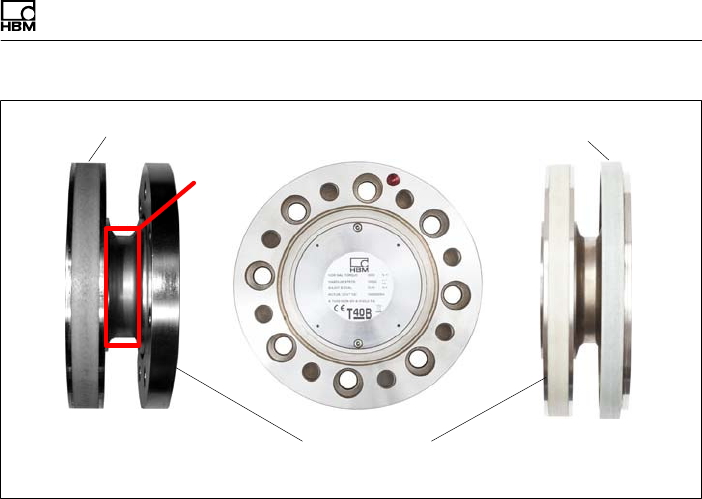
5.6 Installing the stator
On delivery, the stator has already been installed and is
ready for operation. The upper antenna segment can be
separated from the stator, for example, for maintenance
or to facilitate stator mounting, only for Option 7, Code S.
If your application does not require the stator to be dis
mantled, proceed as described in points 2., 5., and 6 for
Option 7, Code S.
Mechanical installation
30 A3452-10.0 T40B
Fan‐type
lock
washers
Hole for fixing the
antenna segment,
diameter 4.2 or
5.2mm,
depending on
maximum capacity
Stator housing
top
Antenna
segment
screws with
washers (M5)
bottom
Antenna
segments
Fig. 5.2 Bolted connection of the antenna segments on the
stator, Option 7, Code S
Stator housing
Antenna segments with mounted shielding plates
Connector plugs
Fig. 5.3 Mechanical construction of Stator with mounted
shielding plates without rotational speed Option 7,
Code U
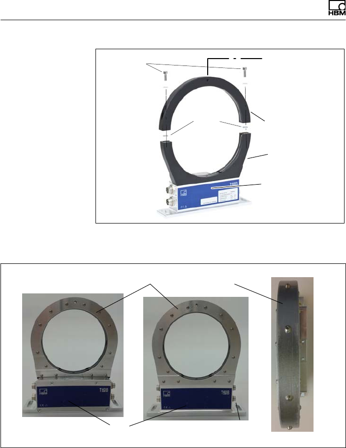
Mechanical installation
T40B A3452-10.0 31
Dismounted shielding plates
Axial shielding
plates
Radial shielding
plate
Fig. 5.4 Individual shielding plates, Option 7, Code U
Important
The use of the shielding plates are important to ensure
compliance with FCC regulations. If the shielding plates
has to be removed for any purpose (e.g. installation or
maintenance), they must be replaced in the original posi
tion before the product is used.
Important
If the shielding plates has to be removed for installation
or maintenance, tighten the screws to fix the shielding
plates with a tightening torque of 0.6 Nm
Mechanical installation
32 A3452-10.0 T40B
Stator housing
lower antenna segment
Antenna wire
T40B without a rotational speed measuring system
T40B with a rotational speed measuring system
Sensor head for measuring rotational speed
Fig. 5.5 Stator housing and lower antenna segment with
antenna wire, Option 7, Code S
1. Undo and remove the bolted connections (M5) on the
upper antenna segment.
There are fan‐type lock washers between the antenna
segments: make sure that they do not get lost.
2. Use an appropriate mounting base to install the stator
housing in the shaft train, so that there is sufficient
opportunity for horizontal and vertical adjustments. Do
not fully tighten the screws yet.
Tip
If your transducer has a sensor for the reference signal,
you should only fit the upper antenna segment after
step 5.

Mechanical installation
T40B A3452-10.0 33
3. Now use two hexagon socket screws to mount the
upper antenna segment removed in Point 1 on the
lower antenna segment.
Make sure that the two fan‐type lock washers are
inserted between the antenna segments (these
ensure that there is a defined contact resistance)!
Important
To make sure that they function perfectly, the fan‐type
lock washers (A5.3-FST DIN 6798 ZN/galvanized) must
be replaced after the bolted antenna connection has
been loosened three times.
4. Now tighten all the bolted antenna segment connec
tions with a tightening torque of 5 N⋅m.
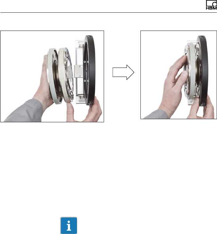
5. Rotational speed measurement without a sensor for
the reference signal (zero index):
Align the antenna to the rotor in such a way that the
antenna encloses the rotor more or less coaxially and
the antenna wire in the axial direction shows the same
position as the center of the transmitter winding on
the rotor.
To make this alignment easier, the antenna segment
and the transmitter winding on flange B have the
same width. Please comply with the permissible align
ment tolerances stated in the specifications.
Mechanical installation
34 A3452-10.0 T40B
Fig. 5.6 Alignment of the rotor with the stator (without a
reference signal sensor), Option 7, Code S and U
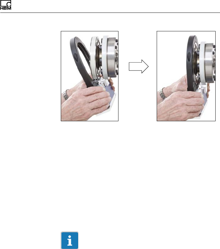
Rotational speed measurement with a sensor for the
reference signal (zero index):
Tilt the stator slightly (see Fig. 5.7, left), so that the
bracket with the sensor head for the reference signal
(zero index) is between the two flanges. Now tip the
stator over the rotor until the antenna ring completely
covers the flange with the transmitter winding (see
Fig. 5.7, right).
Information
If the stator base is already securely installed, you must
remove the upper antenna segment (see steps 1, 3 and
4). Otherwise proceed with the installation as shown in
the photos.
Mechanical installation
T40B A3452-10.0 35
Fig. 5.7 Alignment of the rotor with the stator (with a
reference signal sensor), Option 7, Code S and U
6. Now fully tighten the bolted stator housing connection.
Prevention of axial stator oscillation
Depending on the operating conditions, the stator may be
induced to oscillate. This effect is dependent on:
Sthe rotational speed,
Sthe antenna diameter (depends in turn on the measur
ing range),
Sthe design of the machine base.
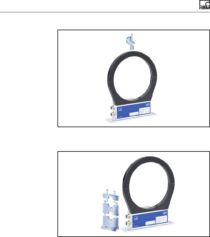
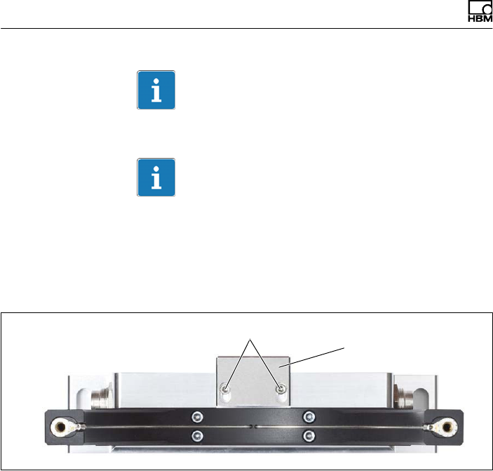
Important
To prevent this axial oscillation, the antenna ring requires
additional support by the customer. There is a socket
(with an M5 internal thread) on the upper antenna seg
ment, which can be used for a suitable clamping device
(see Fig. 5.8). If this is the case, the cable plug also
needs some support, as shown in the construction exam
ple in Fig. 5.9.
Mechanical installation
36 A3452-10.0 T40B
Fig. 5.8 Construction example for supporting the antenna
ring, Option 7, Code S and U
Fig. 5.9 Construction example for plug clamps (for two
plugs), Option 7, Code S and U
Mechanical installation
T40B A3452-10.0 37
5.7 Rotational speed measuring system,
reference signal (optional)
The optional rotational speed measuring system (also
with the additional reference signal and zero index
option) is integrated into the transducer at the factory, so
no installation is required.
Sensor head
for measuring
rotational
speed
Magnetic ring
for rotational
speed
measurement
Sensor head
for the
reference
signal
Fig. 5.10 Torque transducer with rotational speed
measurement and reference signal, Option 7,
Code S and U
Rotational speed measuring system sensor head
alignment
If the stator is accurately aligned for torque measure
ment, the rotational speed measuring system and the
sensor for the reference signal (zero index) are also cor
rectly aligned. So the two Allen screws on the sensor
head (Fig. 5.11) must not be loosened.
Mechanical installation
38 A3452-10.0 T40B
Important
You must not change the position of the sensor head.
Important
This is a magnetic rotational speed measuring system.
In applications where magnetic strengths are expected to
be high (such as an eddycurrent brake), suitable action
must be taken to ensure that the max. magnetic field
strength stated in the specification is not exceeded.
Never loosen the screws! Sensor head for
measuring rotational
speed
Fig. 5.11 Torque transducer with sensor head for rotational
speed measurement, Option 7, Code S and U
Electrical connection
T40B A3452-10.0 39
6 Electrical connection
6.1 General information
SWith extension cables, make sure that there is a
proper connection with minimum contact resistance
and good insulation.
SAll cable connectors or swivel nuts must be fully tight
ened.
Important
Transducer connection cables from HBM with plugs
attached are identified in accordance with their intended
purpose (Md or n). When cables are shortened, inserted
into cable ducts or installed in control cabinets, this iden
tification can get lost or become concealed. So the
cables must be marked beforehand, just in case.
6.2 EMC protection
Important
The transducers are EMC‐tested in accordance with EC
directives and identified by CE certification. However,
you must connect the shield of the connection cable on
the shielding electronics enclosure in order to achieve
EMC protection for the measuring chain.
Special electronic coding methods are used to protect
the purely digital signal transmission between the trans

Electrical connection
40 A3452-10.0 T40B
mitter head and the rotor from electromagnetic interfer
ence.
The cable shield is connected with the transducer hous
ing. This encloses the measurement system (without the
rotor) in a Faraday cage when the shield is laid flat at
both ends of the cable. With other connection tech
niques, an EMCproof shield should be applied in the
wire area, and this shielding should also be connected
extensively (also see HBM Greenline Information,
brochure i1577).
Electrical and magnetic fields often induce interference
voltages in the measuring circuit. Therefore:
SUse shielded, low‐capacitance measurement cables
only (HBM cables fulfill both conditions).
SOnly use plugs that meet EMC guidelines.
SDo not route the measurement cables parallel to
power lines and control circuits. If this is not possible,
protect the measurement cable with e.g. steel con
duit.
SAvoid stray fields from transformers, motors and con
tact switches.
SDo not ground the transducer, amplifier and indicator
more than once.
SConnect all devices in the measuring chain to the
same protective earth conductor.
SIn the case of interference due to potential differences
(compensating currents), the connections between
supply voltage zero and housing ground must be bro
ken at the amplifier and a potential equalization line
established between the stator housing and the ampli
fier housing (copper conductor, at least 10 mm2 wire
cross‐section).

Electrical connection
T40B A3452-10.0 41
SShould differences in potential occur between the
machine rotor and stator because of unchecked leak
age, for example, this can usually be overcome by
connecting the rotor definitively to ground, e.g. with a
wire loop. The stator must be connected to the same
(ground) potential.
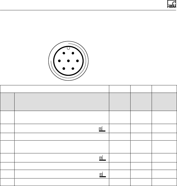
6.3 Connector pin assignment
The stator housing has two 7‐pin plugs, an 8‐pin plug and
a 16‐pin plug.
The supply voltage connections and shunt signal connec
tions of plugs 1 and 3 are each electrically intercon
nected, but are protected against compensating currents
by diodes. There is also a self‐resetting fuse (multifuse)
to protect the supply connections against overload by the
stator.
Note
Torque flanges are only intended for operation with a DC
supply voltage. They must not be connected to older
HBM amplifiers with square‐wave excitation. This could
destroy the connection board resistors or cause other
faults in the amplifiers.
Electrical connection
42 A3452-10.0 T40B
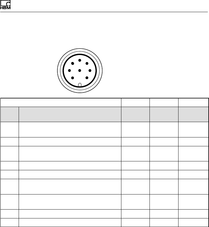
Assignment for plug 1 - Supply voltage and
frequency output signal
61
572
43
Device plug
Top view
KAB153 KAB149 KAB1781)
Plug
pin
Assignment Color
code
D‐SUB‐
plug
pin
HD‐SUB‐
plug
pin
1Torque measurement signal (frequency
output; 5 V2,3)wh 13 5
2Supply voltage 0 V; bk 5 -
3Supply voltage 18 V to 30 V bu 6 -
4Torque measurement signal (frequency
output; 5 V2,3)rd 12 10
5Measurement signal 0 V; symmetrical gy 8 6
6Shunt signal trigger 5 V to 30 V gn 14 15
7Shunt signal 0 V gy 8 -
Shielding connected to housing ground
1) Bridge between 4 + 9
2) RS-422 complementary signals; with cable lengths exceeding 10 m, we recommend using a
termination resistor R = 120 ohms between the (wh) and (rd) wires.
3) RS‐422: pin 1 corresponds to A, pin 4 corresponds to B.
Electrical connection
T40B A3452-10.0 43
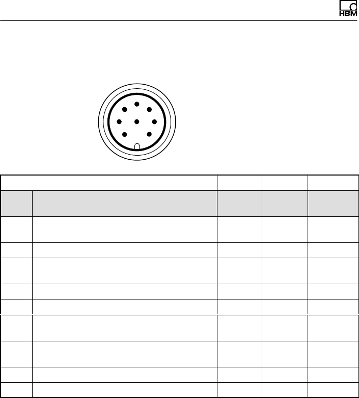
Assignment for plug 2 - Rotational speed
measurement system
6
1
5
7
2
4
38
Device plug
Top view
KAB154 KAB150 KAB1791)
Plug
pin
Assignment Color
code
D-SUB-
plug pin
HD-SUB-
plug pin
1Rotational speed measurement signal2)
(pulse string, 5 V; 0°)rd 12 10
2Not in use bl - -
3Rotational speed measurement signal2)
(pulse string, 5 V; 90°phase shifted) gy 15 8
4Not in use bl - -
5Not in use vi - -
6Rotational speed measurement signal2)
(pulse string, 5 V; 0°)wh 13 5
7Rotational speed measurement signal 2
(pulse string, 5 V; 90°phase shifted) gn 14 7
8Operating voltage zero bk/bl 3) 8 6
Shielding connected to housing ground
1) Bridge between 4 + 9
2) RS-422 complementary signals; with cable lengths exceeding 10 m, we recommend using a
termination resistor of R = 120 ohms.
3) KAB163/KAB164: color code brown (bn)
Electrical connection
44 A3452-10.0 T40B
Assignment for plug 2 - Rotational speed
measurement system with reference signal
Device plug
Top view
6
1
5
7
2
4
38
KAB164 KAB163 KAB1811)
Plug
pin
Assignment Color
code
D-SUB-
plug pin
HD-SUB-
plug pin
1Rotational speed measurement signal 2)
(pulse string, 5 V) rd 12 10
2Reference signal (1 pulse/revolution, 5 V) 2) bl 2 3
3Rotational speed measurement signal 2)
(pulse string, 5 V; 90°phase shifted) gy 15 8
4Reference signal (1 pulse/revolution, 5 V) 2) bl 3 2
5Not in use vi - -
6Rotational speed measurement signal 2)
(pulse string, 5 V; 0°)wh 13 5
7Rotational speed measurement signal 2)
(pulse string, 5 V; 90°phase shifted) gn 14 7
8Operating voltage zero bl 3) 8 6
Shielding connected to housing ground
1) Bridge between 4 + 9
2) RS-422 complementary signals; with cable lengths exceeding 10 m, we recommend using a
termination resistor of R = 120 ohms.
3) KAB163/KAB164: color code brown (bn)
Electrical connection
T40B A3452-10.0 45
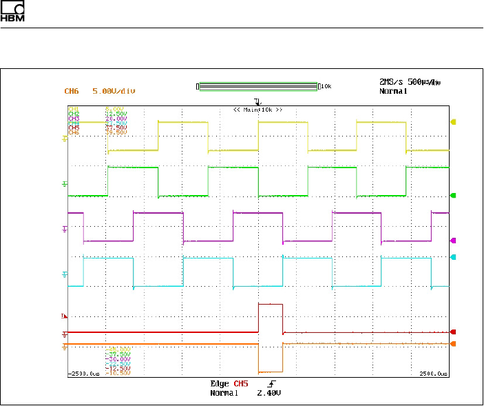
Pin 1
Pin 6
Pin 3
Pin 7
Pin 2
Pin 4
Fig. 6.1 Rotational speed signals at plug 2 (rotational speed
in the direction of the arrow)

Electrical connection
46 A3452-10.0 T40B
Pin 1
Pin 6
Pin 3
Pin 7
Pin 2
Pin 4
Fig. 6.2 Rotational speed signals at plug 2 (rotational speed
against the direction of the arrow)
Electrical connection
T40B A3452-10.0 47
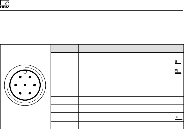
Assignment for plug 3 - Supply voltage and voltage
output signal
61
572
43
Device plug
Top view
Plug pin Assignment
1Torque measurement signal
(voltage output; 0 V)
2Supply voltage 0 V;
3Supply voltage 18 V to 30 V DC
4Torque measurement signal (voltage output;
±10 V)
5Not in use
6Shunt signal trigger 5 V to 30 V
7Shunt signal 0 V;
Shielding connected to housing ground
Assignment for plug 4
TMC - only for connection to the TIM 40/TIM-EC Torque
Interface Module within HBM.
6.4 Supply voltage
The transducer must be operated with a separated
extra‐low voltage (nominal (rated) supply voltage 18 to
30 VDC). You can supply one or more torque flanges
within a test bench at the same time. Should the device
be operated on a DC voltage network1), additional pre
cautions must be taken to discharge excess voltages.
1) Distribution system for electrical energy with greater physical expansion (over several test
benches, for example) that may possibly also supply consumers with high nominal (rated) cur
rents.
Electrical connection
48 A3452-10.0 T40B
The information in this section relates to the self‐con
tained operation of the T40B, without HBM system solu
tions.
The supply voltage is electrically isolated from signal out
puts and shunt signal inputs. Connect a separated
extra‐low voltage of 18 V to 30 V to pin 3 (+) and pin 2
() of plugs 1 or 3. We recommend that you use HBM
cable KAB 8/00-2/2/2 and the appropriate sockets (see
Accessories). The cable can be up to 50 m long for volt
ages ≥24 V, otherwise it can be up to 20 m long.
If the permissible cable length is exceeded, you can feed
the supply voltage in parallel over two connection cables
(plugs 1 and 3). This enables you to double the permissi
ble length. Alternatively, install an on‐site power supply.
Important
The instant you switch on, a current of up to 4 A may
flow and this may switch off power supplies with elec
tronic current limiters.
Shunt signal
T40B A3452-10.0 49
7 Shunt signal
The T40B torque flange delivers an electrical shunt signal
that can be activated from the amplifier in measuring
chains with HBM components. The transducer generates
a shunt signal of about 50% of the nominal (rated)
torque; the precise value is specified on the type plate.
After activation, adjust the amplifier output signal to the
shunt signal supplied by the connected transducer to
adapt the amplifier to the transducer.
Information
The transducer should not be under load when the shunt
signal is being measured, as the shunt signal is mixed
additively.
Triggering the shunt signal
Applying a separated extra‐low voltage of 5 to 30 V to
pins 6 (+) and 7 ( ) at plug 1 or 3, triggers the shunt
signal.
The nominal (rated) voltage for triggering the shunt signal
is 5 V (triggering at U > 2.5 V), but when voltages are
less than 0.7 V, the transducer is in measuring mode.
The maximum permissible voltage is 30 V, current con
sumption at nominal (rated) voltage is approx. 2 mA and
at maximum voltage, approx. 18 mA. The voltage for trig
gering the shunt signal is electrically isolated from the
supply and measuring voltage.
Tip
The shunt signal can be triggered by the amplifier or via
the operating software in HBM system solutions.
Functionality testing
50 A3452-10.0 T40B
8 Functionality testing
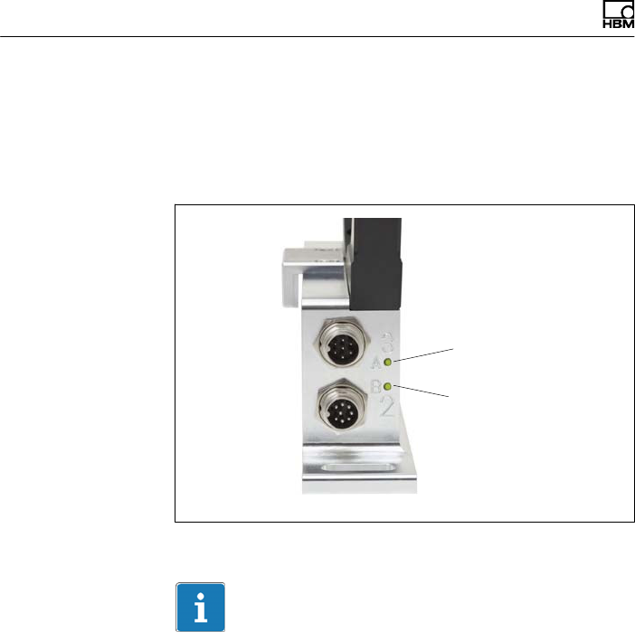
You can check the functionality of the rotor and the stator
from the LEDs on the stator.
LED A, rotor status
LED B, stator status
Fig. 8.1 LEDs on the stator housing
Important
Once the supply voltage is applied, the torque transducer
needs up to a further 4 seconds to be ready for opera
tion.

Functionality testing
T40B A3452-10.0 51
8.1 Rotor status, LED A (upper LED)
Color Significance
Green (pulsating) Internal rotor voltage values ok
Flashing orange
Rotor and stator mismatched (an increasing flashing
frequency indicates the degree of misalignment)
=> Correct the rotor/stator alignment
Pulsating orange
Rotor status cannot be defined
=> Correct the rotor/stator alignment
If the LED still pulsates orange, it is possible that there is a
hardware defect. The measurement signals reflect the level
of the fault.
Red (pulsating)
Rotor voltage values not ok.
=> Correct the rotor/stator alignment
If the LED still pulsates red, it is possible that there is a
hardware defect. The measurement signals reflect the level
of the fault.
Pulsating means that the LED goes dark for about 20 ms
every second (sign of life), making it possible to detect
that the transducer is functioning.

Functionality testing
52 A3452-10.0 T40B
8.2 Stator status, LED B (lower LED)
Color Significance
Green
(permanently lit)
Measurement signal transmission and internal stator
voltages ok
Green, intermittently
orange.
Numerous
synchronization
defects:
permanently orange
Orange until end of defective transmission if y5 incorrect
measured values are transmitted in succession. The
measurement signals reflect the level of the fault for the
duration of the transmission defect + for approx. another 3.3
ms.
Orange
(permanently lit)
Permanently disrupted transmission, the measurement
signals reflect the level of the fault. (fout = 0 Hz, Uout = defect
level).
=> Correct the rotor/stator alignment.
Red
(permanently lit)
Internal stator defect, the measurement signals reflect the
level of the fault (fout = 0 Hz, Uout = defect level).

Load‐carrying capacity
T40B A3452-10.0 53
9 Load‐carrying capacity
Nominal (rated) torque can be exceeded statically up to
the limit torque. If the nominal (rated) torque is exceeded,
additional irregular loading is not permissible. This
includes longitudinal forces, lateral forces and bending
moments. Limit values can be found in Chapter 13
“Specifications”, page 58.
Measuring dynamic torque
The torque flange can be used to measure static and
dynamic torque. The following apply to the measurement
of dynamic torque:
SThe T40B calibration performed for static
measurements is also valid for dynamic torque
measurements.
SThe natural frequency f0 of the mechanical measuring
arrangement depends on the moments of inertia J1
and J2 of the connected rotating masses and the
torsional stiffness of the T40B.
Use the equation below to approximately determine the
natural frequency f0 of the mechanical measuring
arrangement:
f0+1
2p· c
T·ǒ1
J1
)1
J2Ǔ
Ǹf0= natural frequency in Hz
J1, J2= mass moment of inertia in kgVm2
cT= torsional stiffness in NVm/rad
SThe permissible mechanical oscillation width
(peak‐to‐peak) can also be found in the specifications.
Maintenance
54 A3452-10.0 T40B
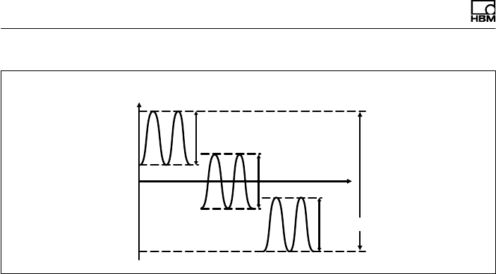
0
+Mnom
200% oscillation width
-Mnom
Nominal (rated) torque Mnom as a %
Time t
Oscillation width
Oscillation width
Oscillation width
Fig. 9.1 Permissible dynamic loading
10 Maintenance
T40B torque flanges are maintenance‐free.

Waste disposal and environmental protection
T40B A3452-10.0 55
11 Waste disposal and environmental protection
All electrical and electronic products must be disposed of
as hazardous waste. The correct disposal of old equip
ment prevents ecological damage and health hazards.
Statutory waste disposal mark
The electrical and electronic devices that bear this sym
bol are subject to the European waste electrical and elec
tronic equipment directive 2002/96/EC. The symbol indi
cates that, in accordance with national and local
environmental protection and material recovery and recy
cling regulations, old devices that can no longer be used
must be disposed of separately and not with normal
household garbage.
As waste disposal regulations may differ from country to
country, we ask that you contact your supplier to deter
mine what type of disposal or recycling is legally applica
ble in your country.
Packaging
The original packaging of HBM devices is made from
recyclable material and can be sent for recycling. Store
the packaging for at least the duration of the warranty. In
the case of complaints, the torque flange must be
returned in the original packaging.
For ecological reasons, empty packaging should not be
returned to us.
= PREFERENCE Types
Ordering numbers, accessories
56 A3452-10.0 T40B
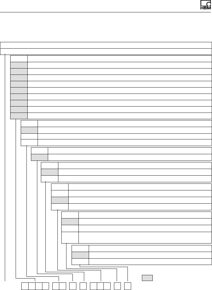
12 Ordering numbers, accessories
Order no.
K-T40B [only with Option 2 = MF / ST]
Code Option 1: Measuring range up to
050Q 50 N·m [only with Option 2 = MF / RO]
100Q 100 N·m [only with Option 2 = MF / RO]
200Q 200 N·m [only with Option 2 = MF / RO]
500Q 500 N·m [only with Option 2 = MF / RO]
001R 1 kN·m [only with Option 2 = MF / RO]
002R 2 kN·m [only with Option 2 = MF / RO]
003R 3 kN·m [only with Option 2 = MF / RO]
005R 4 kN·m [only with Option 2 = MF / RO]
010R 5 kN·m [only with Option 2 = MF / RO]
Code Option 2: Component
MF Measurement flange, complete
RO Rotor
ST Stator
Code Option 3: Accuracy
SStandard
Code Option 4: Nominal (rated) rotational speed
MStandard rotational speed
HHigh rotational speed
Code Option 5: Electrical configuration [only with Option 2 = MF / RO]
SU2 10 kHz ±5 kHz and ±10 V output signal, 18…30V DC supply volt.
DU2 60 kHz ±30 kHz and ±10 V output signal, 18…30V DC supply volt.
HU2 240 kHz ±120 kHz and ±10 V output sign., 18…30V DC sup. volt.
Code Option 6: Rotational speed measuring system
0Without rotational speed measuring system
1Magnetic rot. speed meas. system: 1024 pulses/revolution
AMagnetic rot. speed meas. system (1024 pulses/revolution)
and reference
Code Option 7: Customized modification
SNo customer-specific modification
UUS and Canada version
K-T40B - 0 0 1 R - M F - S - M - D U 2 - 0 - S

Ordering numbers, accessories
T40B A3452-10.0 57
Accessories, to be ordered separately
Article Order no.
Connection cable, set
Torque connection cable, Binder 423 - 15‐pin D‐Sub, 6 m 1-KAB149-6
Torque connection cable, Binder 423 - 7‐pin, free ends, 6 m 1-KAB153-6
Rotational speed connection cable, Binder 423 - 15‐pin D‐Sub, 6 m 1-KAB150-6
Rotational speed connection cable, Binder 423 - 8‐pin, free ends, 6 m 1-KAB154-6
Rotational speed connection cable, reference signal, Binder 423 -
15‐pin D‐Sub, 6 m
1-KAB163-6
Rotational speed connection cable, reference signal, Binder 423 -
8‐pin, free ends, 6 m
1-KAB164-6
TMC connection cable, Binder 423 - 16‐pin, free ends, 6 m 1-KAB174-6
Cable sockets
423G-7S, 7‐pin (straight) 3-3101.0247
423W-7S, 7‐pin (angular) 3-3312.0281
423G-8S, 8‐pin (straight) 3-3312.0120
423W-8S, 8‐pin (angular) 3-3312.0282
Connection cable, by the meter (min. order quantity: 10 m, price per meter)
Kab8/00-2/2/2 4-3301.0071
Specifications
58 A3452-10.0 T40B
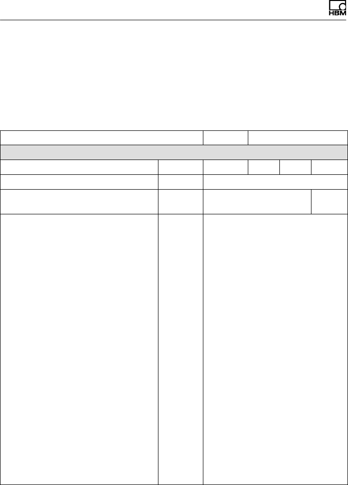
13 Specifications
13.1 Nominal (rated) torque 50N·m to
500N·m
Accuracy class 0.1 0.05
Torque measuring system
Nominal (rated) torque Mnom NVm 50 100 200 500
Nominal (rated) rotational speed rpm 20 000
Nominal (rated) rotational speed,
optional
rpm 24 000 22 000
Non‐linearity including hysteresis,
related to the nominal (rated)
sensitivity
Frequency output
For a max. torque in the range:
between 0% of Mnom and 20% of
Mnom
% <"0.01
> 20% of Mnom and 60% of Mnom % <"0.02
> 60% of Mnom and 100% of Mnom % <"0.03
Voltage output
For a max. torque in the range:
between 0% of Mnom and 20% of
Mnom
% <"0.01
> 20% of Mnom and 60% of Mnom % <"0.02
> 60% of Mnom and 100% of Mnom % <"0.03
Relative standard deviation of
repeatability
per DIN 1319, related to the variation
of the output signal
Frequency output % <"0.03
Voltage output % <"0.03

Specifications
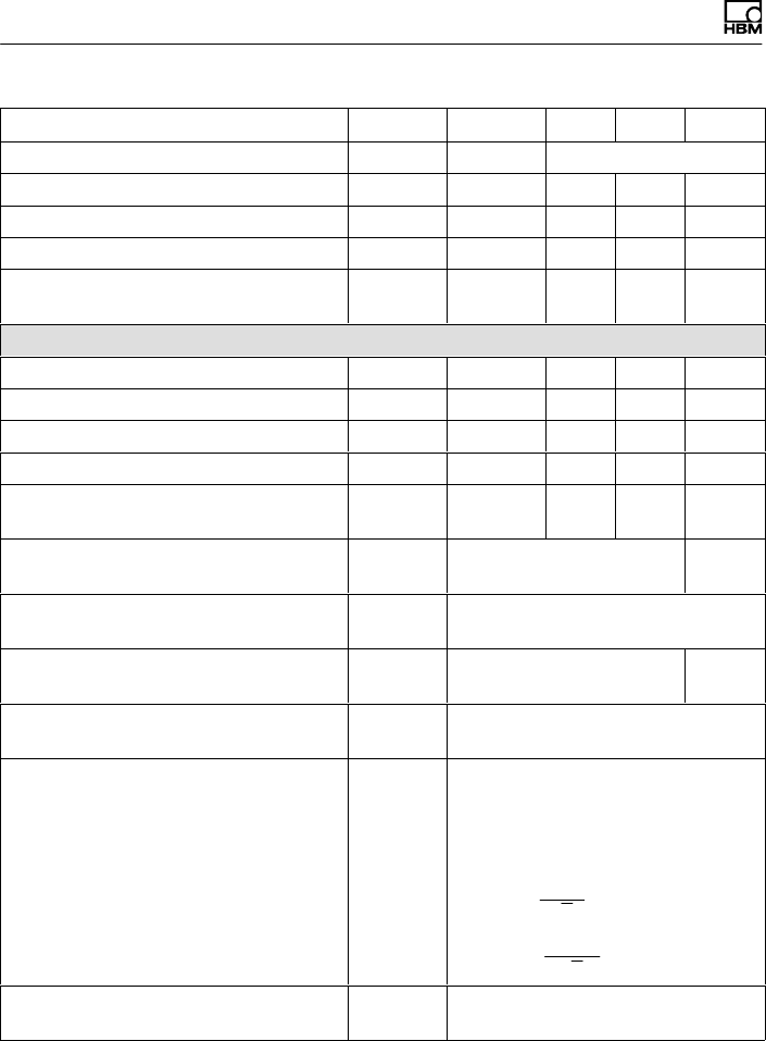
T40B A3452-10.0 59
Nominal (rated) torque Mnom 50020010050NVm
Temperature effect per 10 K in the
nominal (rated) temperature range
on the output signal, related to the
actual value of the signal span
Frequency output %"0.1 "0.05
Voltage output %"0.4 "0.2
on the zero signal, related to the
nominal (rated) sensitivity
Frequency output %"0.1 "0.05
Voltage output %"0.2 "0.1
Nominal (rated) sensitivity
(span between torque = zero and
nominal (rated) torque)
Frequency output 10kHz / 60kHz /
240kHz
kHz 5/30/120
Voltage output V 10
Sensitivity tolerance
(deviation of the actual output quantity
at Mnom from the nominal (rated)
sensitivity)
Frequency output %"0.1
Voltage output %"0.1
Output signal at torque = zero
Frequency output kHz 10/60/240
Voltage output V 0
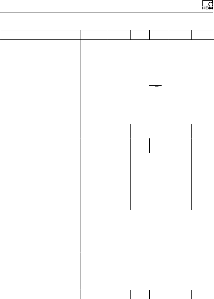
Nominal (rated) output signal
Frequency output
with positive nominal (rated)
torque
kHz 15 1) / 90 2) / 360 3) (5 V symmetri
cal 4))
with negative nominal (rated)
torque
kHz 5 1) / 30 2) / 120 3)
(5 V symmetrical 4))
Voltage output

Specifications
60 A3452-10.0 T40B
Nominal (rated) torque Mnom 50020010050NVm
with positive nominal (rated)
torque
V +10
with negative nominal (rated)
torque
V -10
Load resistance
Frequency output kΩ ≥ 2
Voltage output kΩ ≥ 10
Long‐term drift over 48 h at
reference temperature
Frequency output %t"0.06 t"0.03
Voltage output %t"0.06 t"0.03
Measurement frequency range,
-3 dB
kHz 11) / 32) / 63)
Group delay µst4001) / t2202) / t1503)
Residual ripple
Voltage output 5) mV t40
Maximum modulation range 6)
Frequency output kHz 2.5 to 17.5 1) / 15 to 105 2) / 60 to
420 3)
Voltage output V-12 to +12
Energy supply
Nominal (rated) supply voltage
(separated extra‐low DC voltage)
V18 to 30
Current consumption in measuring
mode
A< 1
Current consumption in startup mode A< 4 (typ. 2) 50 µs
Nominal (rated) power consumption W< 10
Maximum cable length m 50
Shunt signal approx. 50% of Mnom
Tolerance of the shunt signal,
related to Mnom
% <"0.05

Specifications
T40B A3452-10.0 61
Nominal (rated) torque Mnom 50020010050NVm
Nominal (rated) trigger voltage V 5
Trigger voltage limit V 36
Shunt signal ON Vmin. >2.5
Shunt signal OFF Vmax. <0.7
Rotational speed measuring system
Measurement system Magnetic, via AMR sensor
(Anisotropic Resistive Effect) and
magnetized plastic ring with
embedded steel ring
Magnetic poles 72 86
Maximum position deviation of the
poles
50 angular seconds
Output signal V5 V symmetrical (RS-422);
2 square‐wave signals approx. 90°
phase shifted
Pulses per revolution 1024
Minimum rotational speed for
sufficient pulse stability
rpm 0
Pulse tolerance 7) degrees <"0.05
Maximum permissible output
frequency
kHz 420
Group delay µs <150
Radial nominal (rated) distance
between sensor head and magnetic
ring (mechanical distance)
mm 1.6
Working distance range between
sensor head and magnetic ring
mm 0.4 to 2.5
Max. permissible axial
displacement of the rotor to the
stator 8)
mm "1.5
Hysteresis of reversal in the case
of relative vibrations between rotor
and stator

Specifications
62 A3452-10.0 T40B
Nominal (rated) torque Mnom 50020010050NVm
Torsional vibration of the rotor degrees <approx. 0.2
Horizontal stator vibration
displacement
mm <approx. 0.5
Magnetic load limit
Remanent flux density mT >100
Coercive field strength kA/m >100
Permissible magnetic field strength
for signal deviations
kA/m <0.1
Load resistance 9) kΩ≥2
Reference signal measuring system (0 index)
Measurement system Magnetic, with Hall sensor and
magnet
Output signal V5 V symmetrical (RS‐422)
Pulses per revolution 1
Minimum rotational speed for
sufficient pulse stability
rpm 2
Pulse width, approx. degrees 0.088
Pulse tolerance 7degrees <"0.05
Group delay µs <150
Axial nominal (rated) distance
between sensor head and magnetic
ring (mechanical distance)
mm 2.0
Working distance range between
sensor head and magnetic ring
mm 0.4 to 2.5
Max. permissible axial
displacement of the rotor to the
stator 8
mm "1.5
General information
EMC
Emission
(per FCC 47 Part 15, Subpart C) 10)
-

Specifications
T40B A3452-10.0 63
Nominal (rated) torque Mnom 50020010050NVm
Emission
(per EN 61326-1, Section 7)
RFI field strength 11) -Class B
Immunity from interference (EN
61326-1, Table 2)
Electromagnetic field (AM) V/m 10
Magnetic field A/m 100
Electrostatic discharge (ESD)
Contact discharge kV 4
Air discharge kV 8
Fast transients (burst) kV 1
Impulse voltages (surge) kV 1
Conducted interference (AM) V 10
Degree of protection per EN60529 IP 54
Reference temperature °C23
Nominal (rated) temperature range °C+10 to +70
Operating temperature range 12) °C-20 to +85
Storage temperature range °C-40 to +85
Mechanical shock per
EN 60068-2-2713)
Number n 1000
Duration ms 3
Acceleration (half sine) m/s2650
Vibrational stress in three
directions per EN60068-2-6 13)
Frequency range Hz 10 to 2000
Duration h 2.5
Acceleration (amplitude) m/s2200
Load limits 14)
Limit torque, related to Mnom 15) % 400 200
Specifications
64 A3452-10.0 T40B
Nominal (rated) torque Mnom 50020010050NVm
Breaking torque, related to Mnom 15) % 800 > 400
Longitudinal limit force 16) kN 5 5 10 13
Lateral limit force 16) kN 1 1 2 4
Limit bending moment 16) N⋅m 50 50 100 200
Oscillation width per DIN 50100
(peak‐to‐peak) 17)
N⋅m 200 200 400 1000
Mechanical values
Torsional stiffness cTkN⋅m/rad 180 180 360 745
Torsion angle at Mnom degrees 0.016 0.032 0.032 0.038
Stiffness in the axial direction cakN/mm 285 285 540 450
Stiffness in the radial direction crkN/mm 160 160 315 560
Stiffness during the bending
moment round a radial axis cb
kN⋅m/deg. 1.9 1.9 3.6 4.2
Maximum deflection at longitudinal
limit force
mm <0.04 <0.05
Additional max. radial deviation at
lateral limit force
mm <0.02
Additional plumb/parallel deviation
at limit bending moment (at j dB)
mm <0.06 <0.11
Balance quality level per
DIN ISO 1940
G 2.5
Max. limits for relative shaft
vibration (peak‐to‐peak)18)
Undulations in connection flange
area, based on ISO 7919-3
Normal operation (continuous
operation)
µms(p*p) +9000
n
Ǹ(n in rpm)
Start and stop operation/resonance
ranges (temporary)
µms(p*p) +13200
n
Ǹ(n in rpm)
Mass moment of inertia of the
rotor Jv

Specifications
T40B A3452-10.0 65
Nominal (rated) torque Mnom 50020010050NVm
without rotational speed measuring
system
kg⋅m20.0010 0.0010 0.0017 0.0039
with magn. rotational speed
measuring system
kg⋅m20.0015 0.0015 0.0022 0.0048
Proportional mass moment of
inertia for the transmitter side (side
of the flange with external
centering)
without rotational speed measuring
system
% of Jv68 68 62 59
with magn. rotational speed
measuring system
% of Jv44 44 48 48
Max. permissible static eccentricity
of the rotor (radially) to the center
point of the stator
without rotational speed measuring
system
mm "2
Permissible axial displacement
between rotor and stator 19)
without rotational speed measuring
system
mm "2
Weight
Rotor without rotational speed
measuring system
kg 0.7 0.7 1.1 1.9
Rotor with magn. rotational speed
measuring system
kg 0.8 0.8 1.3 2.1
Stator kg 1.1 1.1 1.1 1.1
1) Option 5, 10"5 kHz (code SU2)
2) Option 5, 60"30 kHz (code DU2)
3) Option 5, 240"120 kHz (code HU2)
4) RS-422 complementary signals, note termination resistance.
5) Signal frequency range 0.1 to 10 kHz
6) Output signal range in which there is a repeatable correlation between torque and output signal.
7) At nominal (rated) conditions.
8) The data refers only to a central axial alignment. Deviations lead to a change in pulse tolerance.

Specifications
66 A3452-10.0 T40B
9) Note the required termination resistances as per RS-422.
10) Option 7, Code U
11) Option 7, Code S
12) Heat conductance via the stator base plate necessary over 70°C. The temperature of the base
plate must not exceed 85°C.
13) The antenna ring and connector plug must be fixed.
14) Each type of irregular stress (bending moment, lateral or longitudinal force, exceeding nominal
(rated) torque), can only be permitted up to its specified load limit, provided none of the others can
occur at the same time. If this condition is not met, the limit values must be reduced. If 30% of the
limit bending moment and lateral limit force occur at the same time, only 40% of the longitudinal
limit force is permissible and the nominal (rated) torque must not be exceeded. The effects of
permissible bending moments, longitudinal and lateral forces on the measurement result are
≤±0.3% (50Nm: ≤±0.6%) of the nominal (rated) torque. The load limits only apply for the nominal
(rated) temperature range. At temperatures <10_C, the load limits must be reduced by approx.
30% (strength reduction).
15) With a static loading.
16) Static and dynamic.
17) The nominal (rated) torque must not be exceeded.
18) The influence of radial run‐out deviations, impact, defects of form, notches, marks, local residual
magnetism, structural variations or material anomalies on the vibrational measurements needs to
be taken into account and isolated from the actual undulation.
19) Above the nominal (rated) temperature range: ±1.5mm.
13.2 Nominal (rated) torque 1kN·m to
10kN·m
Accuracy class 0.05
Torque measuring system
Nominal (rated) torque Mnom kNVm 1 2 3 5 10
Nominal (rated) rotational
speed
rpm 20 000 15 000 12 000 10 000
Nominal (rated) rotational
speed, optional
rpm 22 000 16 000 14 000 12 000
Non‐linearity including
hysteresis, related to the
nominal (rated) sensitivity
Frequency output
For a max. torque in the range:

Specifications
T40B A3452-10.0 67
Nominal (rated) torque Mnom 105321kNVm
between 0% of Mnom and
20% of Mnom
% <"0.01
> 20% of Mnom and 60% of
Mnom
% <"0.02
> 60% of Mnom and 100%
of Mnom
% <"0.03
Voltage output
For a max. torque in the range:
between 0% of Mnom and
20% of Mnom
% <"0.01
> 20% of Mnom and 60% of
Mnom
<"0.02
> 60% of Mnom and 100%
of Mnom
<"0.03
Relative standard deviation
of repeatability per DIN 1319,
related to the variation of the
output signal
Frequency output % <"0.03
Voltage output % <"0.03
Temperature effect per 10 K
in the nominal (rated)
temperature range
on the output signal, related to
the actual value of the signal
span
Frequency output %"0.05
Voltage output %"0.2
on the zero signal, related to
the nominal (rated) sensitivity
Frequency output %"0.05
Voltage output %"0.1

Specifications
68 A3452-10.0 T40B
Nominal (rated) torque Mnom 105321kNVm
Nominal (rated) sensitivity
(span between torque = zero
and nominal (rated) torque)
Frequency output 10kHz /
60kHz / 240kHz
kHz 5/30/120
Voltage output V 10
Sensitivity tolerance
(deviation of the actual output
quantity at Mnom from the
nominal (rated) sensitivity)
Frequency output %"0.1
Voltage output %"0.1
Output signal at torque=zero
Frequency output kHz 10/60/240
Voltage output V 0
Nominal (rated) output signal
Frequency output
with positive nominal
(rated) torque
kHz 15 20) / 90 21) / 360 22)
(5 V symmetrical23))
with negative nominal
(rated) torque
kHz 5 20) / 30 21) / 120 22) (5 V symmetrical4))
Voltage output
with positive nominal
(rated) torque
V +10
with negative nominal
(rated) torque
V 10
Load resistance
Frequency output kΩ ≥ 2
Voltage output kΩ ≥ 10
Long‐term drift over 48 h at
reference temperature
Frequency output %t"0.03

Specifications
T40B A3452-10.0 69
Nominal (rated) torque Mnom 105321kNVm
Voltage output %t"0.03
Measurement frequency
range, -3 dB
kHz 1 20) / 3 21) / 6 22)
Group delay µst400 20) / t220 21) / t150 22)
Residual ripple
Voltage output 24) mV t40
Maximum modulation
range 25)
Frequency output kHz 2.5 to 17.5 20) / 15 to 105 21) /
60 to 420 22))
Voltage output V-12 to +12
Energy supply
Nominal (rated) supply voltage
(separated extra‐low DC
voltage)
V18 to 30
Current consumption in
measuring mode
A< 1
Current consumption in startup
mode
A< 4 (typ. 2) 50 µs
Nominal (rated) power
consumption
W< 10
Maximum cable length m 50
Shunt signal approx. 50% of Mnom
Tolerance of the shunt
signal, related to Mnom
% <"0.05
Nominal (rated) trigger voltage V 5
Trigger voltage limit V 36
Shunt signal ON Vmin. >2.5
Shunt signal OFF Vmax. <0.7

Specifications
70 A3452-10.0 T40B
Nominal (rated) torque Mnom 105321kNVm
Rotational speed measuring system
Measurement system Magnetic, via AMR sensor (Anisotropic
Resistive Effect) and magnetized plastic
ring with embedded steel ring
Magnetic poles 86 108 126 156
Maximum position deviation
of the poles
50 angular seconds
Output signal V5 V symmetrical (RS-422);
2 square‐wave signals approx. 90° phase
shifted
Pulses per revolution 1024
Minimum rotational speed
for sufficient pulse stability
rpm 0
Pulse tolerance 26) degrees <"0.05
Maximum permissible output
frequency
kHz 420
Group delay µs <150
Radial nominal (rated)
distance between sensor
head and magnetic ring
(mechanical distance)
mm 1.6
Working distance range
between sensor head and
magnetic ring
mm 0.4 to 2.5
Max. permissible axial
displacement of the rotor to
the stator 27)
mm "1.5
Hysteresis of direction of
rotation reversal in the case
of relative vibrations
between rotor and stator
Torsional vibration of the rotor degrees <approx. 0.2
Horizontal stator vibration
displacement
mm <approx. 0.5

Specifications
T40B A3452-10.0 71
Nominal (rated) torque Mnom 105321kNVm
Magnetic load limit
Remanent flux density mT >100
Coercive field strength kA/m >100
Permissible magnetic field
strength for signal
deviations
kA/m <0.1
Load resistance 28) kΩ≥2
Reference signal measuring system (0 index)
Measurement system Magnetic, with Hall sensor and magnet
Output signal V5 V symmetrical (RS‐422)
Pulses per revolution 1
Minimum rotational speed
for sufficient pulse stability
rpm 2
Pulse width, approx. degrees 0.088
Pulse tolerance 26) degrees <"0.05
Group delay µs <150
Axial nominal (rated)
distance between sensor
head and magnetic ring
(mechanical distance)
mm 2.0
Working distance range
between sensor head and
magnetic ring
mm 0.4 to 2.5
Max. permissible axial
displacement of the rotor to
the stator 27)
mm "1.5
General information
EMC
Emission (per FCC PartC15,
Subpart C) 29)
Emission (per EN 61326-1,
Section 7)

Specifications
72 A3452-10.0 T40B
Nominal (rated) torque Mnom 105321kNVm
RFI field strength 30) -Class B
Immunity from interference
(EN 61326-1, Table 2)
Electromagnetic field (AM) V/m 10
Magnetic field A/m 100
Electrostatic discharge (ESD)
Contact discharge kV 4
Air discharge kV 8
Fast transients (burst) kV 1
Impulse voltages (surge) kV 1
Conducted interference (AM) V 10
Degree of protection per
EN60529
IP 54
Reference temperature °C23
Nominal (rated) temperature
range °C+10 to +70
Operating temperature
range31)°C-20 to +85
Storage temperature range °C-40 to +85-40 to +85
Mechanical shock per
EN60068-2-2732)
Number n 1000
Duration ms 3
Acceleration (half sine) m/s2650
Vibrational stress in 3 direc
tions per EN60068-2-632)
Frequency range Hz 10 to 2000
Duration h 2.5
Acceleration (amplitude) m/s2200
Load limits 33

Specifications
T40B A3452-10.0 73
Nominal (rated) torque Mnom 105321kNVm
Limit torque, related to
Mnom34
% 200 160
Breaking torque, related to
Mnom34
%> 400 > 320
Longitudinal limit force35) kN 19 30 35 60 80
Lateral limit force35) kN 5 9 10 12 18
Limit bending moment 35) N⋅m 220 560 600 800 1200
Oscillation width per
DIN 50100 (peak‐to‐peak) 36)
N⋅m 2000 4000 4800 8000 16000
Mechanical values
Torsional stiffness cTkN⋅m/
rad
1165 2515 3210 5565 14335
Torsion angle at Mnom degrees 0.049 0.046 0.054 0.051 0.040
Stiffness in the axial
direction ca
kN/mm 580 540 570 760 960
Stiffness in the radial
direction cr
kN/mm 860 1365 1680 2080 2940
Stiffness during the bending
moment round a radial
axis cb
kN⋅m/deg. 5.9 9 9.3 20.2 45.5
Maximum deflection at
longitudinal limit force
mm < 0.05 < 0.06 < 0.08 < 0.09
Additional max. radial
deviation at lateral limit force
mm < 0.02
Additional plumb/parallel
deviation at limit bending
moment (at j dB)
mm < 0.09 < 0.18 < 0.19 < 0.14 < 0.12
Balance quality level per
DIN ISO 1940
G 2.5
Specifications
74 A3452-10.0 T40B
Nominal (rated) torque Mnom 105321kNVm
Max. limits for relative shaft
vibration (peak‐to‐peak)37)
Undulations in connection
flange area, based on
ISO 7919-3
Normal operation (continuous
operation)
µms(p*p) +9000
n
Ǹ(n in rpm)
Start and stop operation/
resonance ranges (temporary)
µms(p*p) +13200
n
Ǹ(n in rpm)
Mass moment of inertia of
the rotor Jv
without rotational speed
measuring system
kg⋅m20.0039 0.0128 0.0292 0.0771
with magn. rotational speed
measuring system
kg⋅m20.0048 0.0145 0.0146 0.0333 0.0872
Proportional mass moment
of inertia for the transmitter
side (side of the flange with
external centering)
without rotational speed
measuring system
% of Jv59 54 53 54
with magn. rotational speed
measuring system
% of Jv48 48 47 48
Max. permissible static
eccentricity
of the rotor (radially) to the
center point of the stator
without rotational speed
measuring system
mm "2
Permissible axial
displacement
between rotor and stator 38)
without rotational speed
measuring system
mm "2
Weight

Specifications
T40B A3452-10.0 75
Nominal (rated) torque Mnom 105321kNVm
Rotor without rotational speed
measuring system
kg 1.9 3.8 3.9 6.5 10.9
Rotor with magn. rotational
speed measuring system
kg 2.1 4.1 4.1 6.9 11.7
Stator kg 1.1 1.1 1.1 1.2 1.3
20) Option 5, 10"5 kHz (code SU2)
21) Option 5, 60"30 kHz (code DU2)
22) Option 5, 240"120 kHz (code HU2)
23) RS-422 complementary signals, note termination resistance.
24) Signal frequency range 0.1 to 10 kHz
25) Output signal range in which there is a repeatable correlation between torque and output signal.
26) At nominal (rated) conditions.
27) The data refers only to a central axial alignment. Deviations lead to a change in pulse tolerance.
28) Note the required termination resistances as per RS-422.
29) Option 7, Code U
30) Option 7, Code S
31) Heat conductance via the stator base plate necessary over 70°C. The temperature of the base
plate must not exceed 85°C.
32) The antenna ring and connector plug must be fixed.
33) Each type of irregular stress (bending moment, lateral or longitudinal force, exceeding nominal
(rated) torque), can only be permitted up to its specified load limit, provided none of the others can
occur at the same time. If this condition is not met, the limit values must be reduced. If 30% of the
limit bending moment and lateral limit force occur at the same time, only 40% of the longitudinal
limit force is permissible and the nominal (rated) torque must not be exceeded. The effects of
permissible bending moments, longitudinal and lateral forces on the measurement result are
v"0.3% of the nominal (rated) torque. The load limits only apply for the nominal (rated)
temperature range. At temperatures <10_C, the load limits must be reduced by approx. 30%
(strength reduction).
34) With a static loading.
35) Static and dynamic.
36) The nominal (rated) torque must not be exceeded.
37) The influence of radial deviations, impact, defects of form, notches, marks, local residual
magnetism, structural variations or material anomalies on the vibrational measurements needs to
be taken into account and isolated from the actual undulation.
38) Above the nominal (rated) temperature range: ±1.5mm.
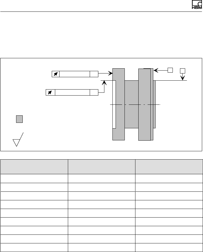
Supplementary technical information
76 A3452-10.0 T40B
14 Supplementary technical information
Axial and radial run‐out tolerances
Internal centering
A
Axial run‐out AB B
Hardness 46 to 54 HRC
Surface quality of the axial and radial
run‐out tolerances (A, B and AB)
0.8
Radial run‐out AB
Measuring range (NVm) Axial run‐out tolerance
(mm)
Radial run‐out tolerance
(mm)
50 0.01 0.01
100 0.01 0.01
200 0.01 0.01
500 0.01 0.01
1 k 0.01 0.01
2 k 0.02 0.02
3 k 0.02 0.02
5 k 0.02 0.02
10 k 0.02 0.02
To ensure that the torque flange retains its properties
once it is installed, we recommend that the customer also
chooses the specified form and position tolerances, sur
face quality and hardness for the connections provided.

Mounting Instructions | Montageanleitung
English Deutsch
T40B

2 A3452-10.0 T40B
Deutsch
1 Sicherheitshinweise 5......................................
2 Verwendete Kennzeichnungen 13.............................
2.1 Auf dem Aufnehmer angebrachte Symbole 13....................
2.2 In dieser Anleitung verwendete Kennzeichnungen 13..............
3 Anwendung 15..............................................
4 Aufbau und Wirkungsweise 16...............................
5 Mechanischer Einbau 22.....................................
5.1 Wichtige Vorkehrungen beim Einbau 22.........................
5.2 Bedingungen am Einbauort 23..................................
5.3 Einbaulage 24................................................
5.4 Einbaumöglichkeiten 24.......................................
5.4.1 Einbau mit nicht demontiertem Antennenring, Option 7, Code U mit
Antennen-Abschirmungsabdeckung 25..........................
5.4.2 Einbau mit nachträglicher Montage des Stators, Option 7, Code S 26
5.5 Montage des Rotors 27........................................
5.6 Montage des Stators 31.......................................
5.7 Drehzahlmesssystem, Referenzimpuls (optional) 39...............
6 Elektrischer Anschluss 41....................................
6.1 Allgemeine Hinweise 41.......................................
6.2 EMV‐Schutz 41...............................................
6.3 Steckerbelegung 43...........................................
6.4 Versorgungsspannung 49......................................
7 Shuntsignal 51..............................................
8 Funktionsprüfung 53........................................
8.1 Rotorstatus, LED A (obere LED) 54.............................
8.2 Statorstatus, LED B (untere LED) 54............................

T40B A3452-10.0 3
9 Belastbarkeit 56.............................................
10 Wartung 57..................................................
11 Entsorgung und Umweltschutz 58............................
12 Bestellnummern, Zubehör 59.................................
13 Technische Daten 61.........................................
13.1 Nenndrehmoment 50N·m bis 500N·m 61........................
13.2 Nenndrehmoment 1kN·m bis 10kN·m 70........................
14 Ergänzende technische Informationen 80.....................
15 Dimensions | Abmessungen 81...............................
15.1 T40B without rotational speed measurement |
T40B ohne Drehzahlmessung 81...............................
15.1.1 T40B 50Nm - 100Nm, Option 7, Code S 81.....................
15.1.2 T40B 50 Nm, 100 Nm, Option 7, Code U 83......................
15.1.3 T40B 200Nm, Option 7, Code S 85.............................
15.1.4 T40B 200 Nm, Option 7, Code U 87.............................
15.1.5 T40B 500Nm - 1kNm, Option 7, Code S 89.....................
15.1.6 T40B 500 Nm - 1 kNm, Option 7, Code U 91.....................
15.1.7 T40B 2kNm - 3kNm, Option 7, Code S 93.......................
15.1.8 T40B 2 kNm - 3 kNm, Option 7, Code U 95......................
15.1.9 T40B 5kNm, Option 7, Code S 97..............................
15.1.10 T40B 5 kNm, Option 7, Code U 99..............................
15.1.11 T40B 10kNm, Option 7, Code S 101.............................
15.1.12 T40B 10 kNm, Option 7, Code U 103.............................
15.2 T40B with rot. speed measurement and reference signal | mit
Drehzahlmessung und Referenzimpuls 105........................
15.2.1 T40B 50Nm - 100Nm, Option 7, Code S 105.....................
15.2.2 T40B 50 kNm - 100 Nm, Option 7, Code U 107....................
15.2.3 T40B 200Nm, Option 7, Code S 109.............................

4 A3452-10.0 T40B
15.2.4 T40B 200 Nm, Option 7, Code U 111.............................
15.2.5 T40B 500Nm - 1kNm, Option 7, Code S 113.....................
15.2.6 T40B 500 Nm - 1 kNm, Option 7, Code U 115.....................
15.2.7 T40B 2kNm - 3kNm, Option 7, Code S 117.......................
15.2.8 T40B 2 kNm - 3 kNm, Option 7, Code U 119......................
15.2.9 T40B 5kNm, Option 7, Code S 121..............................
15.2.10 T40B 5 kNm, Option 7, Code U 123..............................
15.2.11 T40B 10kNm, Option 7, Code S 125.............................
15.2.12 T40B 10 kNm, Option 7, Code U 127.............................
Sicherheitshinweise
T40B A3452-10.0 5
1 Sicherheitshinweise
FCC-Konformität und Hinweis für Option 7, Code U
Wichtig
Durch Änderungen, die nicht ausdrücklich schriftlich von
der für die Konformität zuständigen Person genehmigt
wurden, könnte die Berechtigung zum Betrieb des Geräts
verfallen. Sofern angegeben, müssen zusätzliche
Komponenten oder Zubehörteile, deren Verwendung bei
der Installation des Produkts an anderer Stelle vorgege
ben ist, verwendet werden, um die Einhaltung der FCC-
Vorschriften zu gewährleisten.
Dieses Gerät entspricht Teil 15 der FCC-Vorschriften.
Der Betrieb unterliegt den beiden nachstehenden
Bedingungen: (1) Dieses Gerät darf keine schädlichen
Störungen verursachen und (2) dieses Gerät muss Stö
rungen akzeptieren können, auch solche, die ein
unerwünschtes Betriebsverhalten zur Folge haben
können.
Die FCC-Kennung bzw. die eindeutige Kennung muss
am Gerät sichtbar sein.
Modell Messbereiche FCC ID IC
T40S2TOS6
50 Nm, 100 Nm,
200 Nm
2ADAT−T40S2TOS6 12438A−T40S2TOS6
500 Nm, 1 kNm
2 kNm, 3 kNm
5 kNm
10 kNm
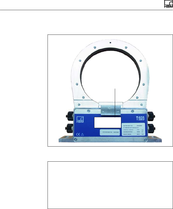
Sicherheitshinweise
6 A3452-10.0 T40B
Beispiel eines Schildes mit FCC-ID und IC-Nummer.
Model: T40S2TOS6
FCC ID: 2ADAT-T40S2TOS6
IC: 12438AT40S2TOS6
This device complies with part 15 of the FCC Rules. Opera
tion is subject to the following two conditions: (1) This device
may not cause harmful interference, and (2) this device must
accept any interference received, including interference that
may cause undesired operation.
Schild
Abb. 1.1 Position des Schildes am Stator des Geräts
Model: T40S2TOS6
FCC ID: 2ADAT-T40S2TOS6
IC: 12438AT40S2TOS6
This device complies with part 15 of the FCC Rules. Operation is
subject to the following two conditions: (1) This device may not
cause harmful interference, and (2) this device must accept any
interference received, including interference that may cause
undesired operation.
Abb. 1.2 Beispiel eines Schildes

Sicherheitshinweise
T40B A3452-10.0 7
Industry Canada für Option 7, Code U
Darmstadt, 13.11.2014
Dieses Produkt hat die IC-Freigabe ((Industry Canada
Approval) noch nicht erreicht. Der Zertifizierungsprozess
läuft zur Zeit noch. HBM erwartet das Zertifikat bis Ende
Dezember 2014.
Ihr lokaler HBM-Ansprechpartner wird Ihre möglichen
Fragen bezüglich der IC Zertifizierung gerne beant
worten.
Darmstadt, 2014-11-13
This product has not yet received IC (Industry Canada)
approval. The certification process for this product is still
under way. HBM currently expects that IC approval will
be granted by the end of December 2014.
Your local HBM contact looks forward to answer any
questions you may have regarding IC approval.
Darmstadt, le 13 novembre 2014
Ce produit n'a pas encore obtenu l'approbation IC (Indus
trie Canada). Le produit est encore en processus de
certification. Actuellement, HBM suppose que l'appro
bation IC sera accordée jusqu'à fin décembre 2014.
Si vous avez des questions au sujet de l'approbation IC,
veuillez vous adresser à votre représentation HBM sur
place.
Dieses Gerät entspricht der Industry-Canada-Norm
RSS210.
Dieses Gerät entspricht der bzw. den RSS-Normen von
Industry Canada für nicht genehmigungspflichtige
Geräte. Der Betrieb unterliegt den beiden nachstehenden
Bedingungen: (1) Dieses Gerät darf keine Störungen ver
ursachen und (2) dieses Gerät muss Störungen akzep

Sicherheitshinweise
8 A3452-10.0 T40B
tieren können, auch solche, die ein unerwünschtes
Betriebsverhalten des Geräts zur Folge haben können.
This device complies with Industry Canada standard
RSS210.
This device complies with Industry Canada
license‐exempt RSS standard(s).Operation is subject to
the following two conditions: (1) this device may not
cause interference, and (2) this device must accept any
interference, including interference that may cause unde
sired operation of the device.
Cet appareil est conforme aux norme RSS210 d’Industrie
Canada.
Cet appareil est conforme aux normes d’exemption de
licence RSS d’Industry Canada. Son fonctionnement est
soumis aux deux conditions suivantes : (1)cet appareil ne
doit pas causer d’interférence et (2) cet appareil doit
accepter toute interférence, notamment les interférences
qui peuvent affecter son fonctionnement.
Bestimmungsgemäße Verwendung
Der Drehmoment‐Messflansch T40B ist für Dreh
moment‐, Drehwinkel‐ und Leistungs‐Messaufgaben im
Rahmen der durch die technischen Daten spezifizierten
Belastungsgrenzen konzipiert. Jeder andere Gebrauch
ist nicht bestimmungsgemäß.
Der Betrieb des Stators ist nur mit montiertem Rotor
zulässig.
Der Drehmoment‐Messflansch darf nur von qualifiziertem
Personal ausschließlich entsprechend der technischen
Daten unter Beachtung der Sicherheitsbestimmungen
und Vorschriften dieser Montageanleitung eingesetzt
werden. Zusätzlich sind die für den jeweiligen Anwen
dungsfall geltenden Rechts‐ und Sicherheitsvorschriften

Sicherheitshinweise
T40B A3452-10.0 9
zu beachten. Sinngemäß gilt dies auch bei Verwendung
von Zubehör.
Der Drehmoment‐Messflansch ist nicht zum Einsatz als
Sicherheitsbauteil bestimmt. Bitte beachten Sie hierzu
den Abschnitt „Zusätzliche Sicherheitsvorkehrungen“.
Der einwandfreie und sichere Betrieb setzt sachgemäßen
Transport, fachgerechte Lagerung, Aufstellung und
Montage sowie sorgfältige Bedienung voraus.
Belastbarkeitsgrenzen
Beim Einsatz des Drehmoment‐Messflanschs sind die
Angaben in den technischen Datenblättern unbedingt zu
beachten. Insbesondere dürfen die jeweils angegebenen
Maximalbelastungen keinesfalls überschritten werden.
Nicht überschritten werden dürfen z.B. die in den
technischen Daten angegebenen Werte für
SGrenzdrehmoment,
SGrenzlängskraft, Grenzquerkraft oder Grenz
biegemoment,
SSchwingbreite des Drehmoments,
SBruchdrehmoment,
STemperaturgrenzen,
Sdie Grenzen der elektrischen Belastbarkeit.
Einsatz als Maschinenelemente
Der Drehmoment‐Messflansch kann als Maschinen
element eingesetzt werden. Bei dieser Verwendung ist zu
beachten, dass der Aufnehmer zu Gunsten einer hohen
Messempfindlichkeit nicht mit den im Maschinenbau übli
chen Sicherheitsfaktoren konstruiert wurde. Beachten
Sie hierzu den Abschnitt „Belastbarkeitsgrenzen“ und die
technischen Daten.

Sicherheitshinweise
10 A3452-10.0 T40B
Unfallverhütung
Entsprechend den einschlägigen Unfallverhütungsvor
schriften der Berufsgenossenschaften ist nach der
Montage des Aufnehmers vom Betreiber eine Abdeckung
oder Verkleidung wie folgt anzubringen:
SAbdeckung oder Verkleidung dürfen nicht mitrotieren.
SAbdeckung oder Verkleidung sollen sowohl Quetsch‐
und Scherstellen vermeiden als auch vor evtl. sich
lösenden Teilen schützen.
SAbdeckungen und Verkleidungen müssen weit genug
von den bewegten Teilen entfernt oder so beschaffen
sein, dass man nicht hindurchgreifen kann.
SAbdeckungen und Verkleidungen müssen auch ange
bracht sein, wenn die bewegten Teile des Dreh
moment‐Messflanschs außerhalb des Verkehrs‐ und
Arbeitsbereiches von Personen installiert sind.
Von den vorstehenden Forderungen darf nur abgewichen
werden, wenn der Drehmoment‐Messflansch schon
durch den Aufbau der Maschine oder bereits vorhandene
Schutzvorkehrungen ausreichend gesichert ist.
Zusätzliche Sicherheitsvorkehrungen
Der Drehmoment‐Messflansch kann (als passiver Auf
nehmer) keine (sicherheitsrelevanten) Abschaltungen
vornehmen. Dafür bedarf es weiterer Komponenten und
konstruktiver Vorkehrungen, für die der Errichter und
Betreiber der Anlage Sorge zu tragen hat. Die das Mess
signal verarbeitende Elektronik ist so zu gestalten, dass
bei Ausfall des Messsignals keine Folgeschäden auftre
ten können.
Der Leistungs‐ und Lieferumfang des Aufnehmers deckt
nur einen Teilbereich der Drehmoment‐Messtechnik ab.
Sicherheitstechnische Belange sind vom Anlagenplaner/

Sicherheitshinweise
T40B A3452-10.0 11
Ausrüster/Betreiber so zu planen, zu realisieren und zu
verantworten, dass Restgefahren minimiert werden. Die
jeweils existierenden nationalen und örtlichen Vorschrif
ten sind zu beachten.
Allgemeine Gefahren bei Nichtbeachten der
Sicherheitshinweise
Der Drehmoment‐Messflansch entspricht dem Stand der
Technik und ist betriebssicher. Von dem Aufnehmer
können Gefahren ausgehen, wenn er von ungeschultem
Personal oder unsachgemäß montiert, aufgestellt, einge
setzt und bedient werden. Jede Person, die mit Aufstel
lung, Inbetriebnahme, Betrieb oder Reparatur eines
Drehmoment‐Messflanschs beauftragt ist, muss die
Montageanleitung und insbesondere die sicherheits
technischen Hinweise gelesen und verstanden haben.
Bei nicht bestimmungsgemäßem Gebrauch des Aufneh
mers, bei Nichtbeachtung der Montage‐ und Bedienungs
anleitung, dieser Sicherheitshinweise oder sonstiger ein
schlägiger Sicherheitsvorschriften
(Unfallverhütungsvorschriften der BG) beim Umgang mit
dem Aufnehmer, kann der Aufnehmer beschädigt oder
zerstört werden. Insbesondere bei Überlastungen kann
es zum Bruch des Aufnehmers kommen. Durch den
Bruch können darüber hinaus Sachen oder Personen in
der Umgebung des Aufnehmers zu Schaden kommen.
Wird der Drehmoment‐Messflansch nicht seiner Bestim
mung gemäß eingesetzt oder werden die Sicherheitshin
weise oder die Vorgaben der Montage‐ oder Bedienungs
anleitung außer Acht gelassen, kann es ferner zum
Ausfall oder zu Fehlfunktionen des Aufnehmers kommen,
mit der Folge, dass (durch auf den Drehmoment‐Mess
flansch einwirkende oder durch diesen überwachte Dreh
momente) Menschen oder Sachen zu Schaden kommen
können.

Sicherheitshinweise
12 A3452-10.0 T40B
Umbauten und Veränderungen
Der Aufnehmer darf ohne unsere ausdrückliche Zustim
mung weder konstruktiv noch sicherheitstechnisch
verändert werden. Jede Veränderung schließt eine Haf
tung unsererseits für daraus resultierende Schäden aus.
Veräußerung
Bei einer Veräußerung des Drehmoment‐Messflanschs
ist diese Montageanleitung dem Drehmoment‐Mess
flansch beizulegen.
Qualifiziertes Personal
Qualifiziertes Personal sind Personen, die mit Aufstel
lung, Montage, Inbetriebsetzung und Betrieb des Pro
duktes vertraut sind und die über die ihrer Tätigkeit ent
sprechende Qualifikationen verfügen.
Dazu zählen Personen, die mindestens eine der drei
folgenden Voraussetzungen erfüllen:
1. Ihnen sind die Sicherheitskonzepte der Automa
tisierungstechnik bekannt und Sie sind als Projektper
sonal damit vertraut.
2. Sie sind Bedienungspersonal der Automatisierungs
anlagen und im Umgang mit den Anlagen
unterwiesen. Sie sind mit der Bedienung der in dieser
Dokumentation beschriebenen Geräte und Technolo
gien vertraut.
3. Sie sind Inbetriebnehmer oder für den Service einge
setzt und haben eine Ausbildung absolviert, die Sie
zur Reparatur der Automatisierungsanlagen befähigt.
Außerdem haben Sie eine Berechtigung, Stromkreise
und Geräte gemäß den Normen der Sicherheits
technik in Betrieb zu nehmen, zu erden und zu kenn
zeichnen.
Verwendete Kennzeichnungen
T40B A3452-10.0 13
2 Verwendete Kennzeichnungen
2.1 Auf dem Aufnehmer angebrachte
Symbole
Angaben in dieser Anleitung nachlesen und
berücksichtigen
CE‐Kennzeichnung
Mit der CE‐Kennzeichnung garantiert der Hersteller, dass
sein Produkt den Anforderungen der relevanten EG‐
Richtlinien entspricht (die Konformitätserklärung finden
Sie auf www.hbm.com unter HBMdoc).
Beispiel eines Schildes
Beispiel eines Schildes mit FCC-ID und IC-Nummer,
Option 7, Code U. Position des Schildes am Stator des
Geräts.
2.2 In dieser Anleitung verwendete
Kennzeichnungen
Wichtige Hinweise für Ihre Sicherheit sind besonders ge
kennzeichnet. Beachten Sie diese Hinweise unbedingt,
um Unfälle und Sachschäden zu vermeiden.
Model: T40S2TOS6
FCC ID: 2ADAT-T40S2TOS6
IC: 12438AT40S2TOS6
This device complies with part 15 of the
FCC Rules. Operation is subject to the
following two conditions: (1) This device
may not cause harmful interference, and
(2) this device must accept any interfer
ence received, including interference that
may cause undesired operation.
Verwendete Kennzeichnungen
14 A3452-10.0 T40B
Symbol Bedeutung
WARNUNG Diese Kennzeichnung weist auf eine mögliche
gefährliche Situation hin, die – wenn die Sicherheits
bestimmungen nicht beachtet werden – Tod oder
schwere Körperverletzung zur Folge haben kann.
VORSICHT Diese Kennzeichnung weist auf eine mögliche
gefährliche Situation hin, die – wenn die Sicherheits
bestimmungen nicht beachtet werden – leichte oder
mittlere Körperverletzung zur Folge haben kann.
Hinweis Diese Kennzeichnung weist auf eine Situation hin,
die – wenn die Sicherheitsbestimmungen nicht
beachtet werden – Sachschäden zur Folge haben
kann.
Wichtig
Diese Kennzeichnung weist auf wichtige Informa
tionen zum Produkt oder zur Handhabung des Pro
duktes hin.
Tipp
Diese Kennzeichnung weist auf Anwendungstipps
oder andere für Sie nützliche Informationen hin.
Information
Diese Kennzeichnung weist auf Informationen zum
Produkt oder zur Handhabung des Produktes hin.
Hervorhebung
Siehe …
Kursive Schrift kennzeichnet Hervorhebungen im
Text und kennzeichnet Verweise auf Kapitel, Bilder
oder externe Dokumente und Dateien.

Anwendung
T40B A3452-10.0 15
3 Anwendung
Der Drehmoment‐Messflansch T40B erfasst statische
und dynamische Drehmomente an ruhenden oder rotie
renden Wellen. Der Aufnehmer ermöglicht durch seine
kurze Bauweise äußerst kompakte Prüfaufbauten.
Dadurch ergeben sich vielfältige Anwendungen.
Der Drehmomentflansch T40B verfügt über einen
zuverlässigen Schutz vor elektromagnetischen Stö
rungen. Er wurde gemäß harmonisierten europäischen
Normen getestet und/oder entspricht US-amerikanischen
und kanadischen Normen. Am Produkt befindet sich das
CE-Kennzeichen und/oder das FCC-Schild.

Aufbau und Wirkungsweise
16 A3452-10.0 T40B
4 Aufbau und Wirkungsweise
Der Drehmoment‐Messflansch besteht aus zwei getrenn
ten Teilen, dem Rotor und dem Stator. Der Rotor setzt
sich zusammen aus dem Messkörper und den Signal‐
Übertragungselementen.
Auf dem Messkörper sind Dehnungsmessstreifen (DMS)
installiert. Die Rotorelektronik für die Brückenspeisespan
nungs‐ und Messsignalübertragung ist zentrisch im
Flansch angeordnet. Der Messkörper trägt am äußeren
Umfang die Übertragerspulen für die berührungslose
Übertragung von Speisespannung und Messsignal. Die
Signale werden von einem teilbaren Antennenring gesen
det bzw. empfangen. Abnehmbarer Antennenring nicht
für Option 7, Code U. Der Antennenring ist auf einem
Gehäuse befestigt, in dem die Elektronik für die Span
nungsanpassung sowie die Signalaufbereitung unterge
bracht sind.
Am Stator befinden sich Anschlussstecker für das Dreh
moment‐ und das Drehzahlsignal, die Spannungsversor
gung und den digitalen Ausgang. Die Antennensegmente
(der Antennenring) müssen konzentrisch um den Rotor
montiert werden (siehe Kapitel 5).
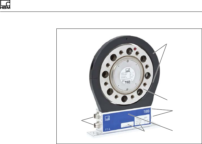
Aufbau und Wirkungsweise
T40B A3452-10.0 17
Antennen
segmente
Rotor
Anschluss
stecker
Stator
gehäuse
Typenschild
Anschluss
stecker
Abb. 4.1 Mechanischer Aufbau ohne Drehzahlmesssystem,
Option 7, Code S
Bei der Option 6 mit Drehzahlmesssystem ist auf dem
Stator der Drehzahlsensor montiert. Die Drehzahl
messung erfolgt magnetisch mittels AMR‐Sensor und
Magnetring. Der Magnetring für die Drehzahlerfassung ist
auf dem Flansch aufgeschweißt.
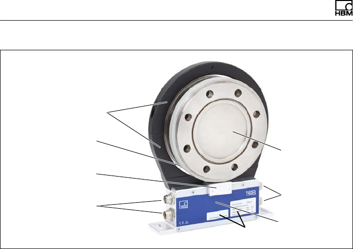
Aufbau und Wirkungsweise
18 A3452-10.0 T40B
Antennensegmente
Rotor
Anschlussstecker
Statorgehäuse
Typenschild
Anschlussstecker
Sensorkopf für
Drehzahlmessung
Magnetring für
Drehzahlmessung
Abb. 4.2 Mechanischer Aufbau mit Drehzahlmesssystem,
Option 7, Code S
Bei der Ausführung mit Drehzahlmesssystem kann der
Aufnehmer zusätzlich mit einem Sensorkopf für einen
Referenzimpuls (Null‐Index) zur Drehwinkelmessung
versehen werden. Hierbei befindet sich der dazu
verwendete Magnet auf der Innenseite des Flansches.
Der Sensorkopf zur Abtastung des Referenzimpulses
befindet sich in dem Bügel oberhalb des Drehzahl
sensors.
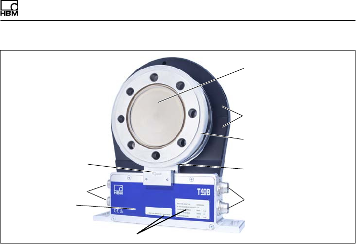
Aufbau und Wirkungsweise
T40B A3452-10.0 19
Antennensegmente
Rotor
Anschlussstecker
Statorgehäuse
Typenschild
Anschlussstecker
Sensorkopf für
Drehzahlmessung
Magnetring für
Drehzahlmessung
Sensorkopf für
Referenzimpuls
Abb. 4.3 Mechanischer Aufbau mit Drehzahlmesssystem und
Sensor für Referenzimpuls (Null‐Index), Option 7,
Code S
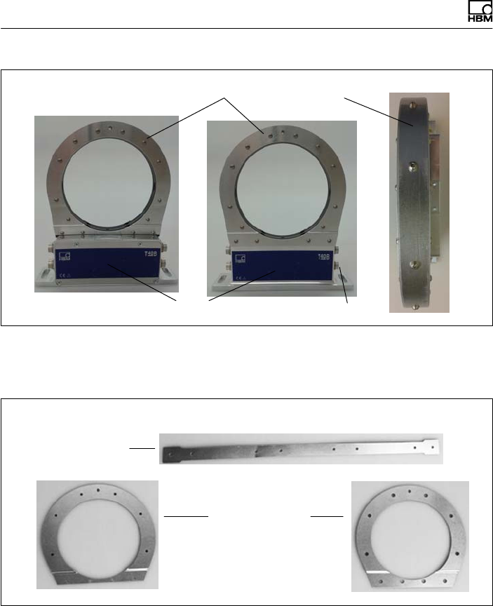
Aufbau und Wirkungsweise
20 A3452-10.0 T40B
Statorgehäuse
Antennensegmente mit montierten Abschirmungsplatten
Anschlüsse
Abb. 4.4 Mechanischer Aufbau des Stators mit montierten
Abschirmungsplatten ohne Drehzahlmesssystem,
Option 7, Code U
Abmontierte Abschirmungsplatten
Axiale Abschirmungs
platten
Radiale
Abschirmungsplatte
Abb. 4.5 Einzelne Abschmirmungsplatten, Option 7, Code U

Aufbau und Wirkungsweise
T40B A3452-10.0 21
Information
Der mechanische Aufbau mit Drehzahlmesssystem ist
mit Abb. 4.2 identisch und verfügt über eine zusätzliche
Abschirmungsplatte für den Antennenring, siehe
Abb. 4.4.
Wichtig
Um die Einhaltung der FCC-Vorschriften zu gewährleis
ten, müssen die Abschirmungsplatten unbedingt
verwendet werden. Müssen die Abschirmungsplatten zu
irgendeinem Zweck entfernt werden (z. B. zur Installation
oder Wartung), müssen sie in der ursprünglichen Position
wieder angebracht werden, bevor das Gerät in Betrieb
genommen wird.

Mechanischer Einbau
22 A3452-10.0 T40B
5 Mechanischer Einbau
5.1 Wichtige Vorkehrungen beim Einbau
Hinweis
Ein Drehmoment‐Messflansch ist ein Präzisions‐Mess
element und verlangt daher eine umsichtige Hand
habung. Stöße oder Stürze können zu permanenten
Schäden am Aufnehmer führen. Sorgen Sie dafür, dass
auch bei der Montage keine Überlastung des Aufneh
mers auftreten kann.
SBehandeln Sie den Aufnehmer schonend.
SPrüfen Sie den Einfluss von Biegemomenten, kri
tischen Drehzahlen und Torsionseigenschwingungen,
um eine Überlastung des Aufnehmers durch Reso
nanzüberhöhungen zu vermeiden.
SStellen Sie sicher, dass der Aufnehmer nicht
überlastet werden kann.
WARNUNG
Bei einer Überlastung des Aufnehmers besteht die
Gefahr, dass der Aufnehmer bricht. Dadurch können
Gefahren für das Bedienpersonal der Anlage auftreten, in
die der Aufnehmer eingebaut ist.
Treffen Sie geeignete Sicherungsmaßnahmen zur
Vermeidung einer Überlastung und zur Sicherung gegen
sich daraus ergebende Gefahren.

Mechanischer Einbau
T40B A3452-10.0 23
SKleben Sie die Verbindungsschrauben mit einer
Schraubensicherung (mittelfest, z.B. von LOCTITE)
in das Gegengewinde ein, um einen Vorspannverlust
durch Lockern auszuschließen, falls Wechsellasten zu
erwarten sind.
SHalten Sie die Montagemaße unbedingt ein, um einen
einwandfreien Betrieb zu ermöglichen.
Der Drehmoment‐Messflansch T40B kann über einen
entsprechenden Wellenflansch direkt montiert werden.
Am Rotor ist auch die direkte Montage einer Gelenkwelle
oder entsprechender Ausgleichselemente (bei Bedarf
über Zwischenflansch) möglich. Die zulässigen Grenzen
für Biegemomente, Quer‐ und Längskräfte dürfen jedoch
in keinem Fall überschritten werden. Durch die hohe
Drehsteifigkeit des Aufnehmers T40B werden dynami
sche Veränderungen des Wellenstrangs gering gehalten.
Wichtig
Auch bei korrektem Einbau kann sich der im Werk ab
geglichene Nullpunkt bis zu ca. 2% vom Kennwert ver
schieben. Wird dieser Wert überschritten, empfehlen wir,
die Einbausituation zu prüfen. Ist der bleibende Null
punktversatz im ausgebauten Zustand größer als 1%
vom Kennwert, senden Sie den Aufnehmer bitte zur Prü
fung ins Werk Darmstadt.
5.2 Bedingungen am Einbauort
Der Drehmoment‐Messflansch T40B muss vor grobem
Schmutz, Staub, Öl, Lösungsmitteln und Feuchtigkeit
geschützt werden.

Mechanischer Einbau
24 A3452-10.0 T40B
Der Aufnehmer ist in weiten Grenzen gegen Temperatu
reinflüsse auf das Ausgangs‐ und Nullsignal kompensiert
(siehe Kapitel „Technische Daten“). Liegen keine statio
nären Temperaturverhältnisse vor, z.B. durch Tempera
turunterschiede zwischen Messkörper und Flansch, kön
nen die in den technischen Daten spezifizierten Werte
überschritten werden. Sorgen Sie in diesen Fällen je
nach Anwendungsfall durch Kühlung oder Heizung für
stationäre Temperaturverhältnisse. Prüfen Sie alternativ,
ob eine Temperaturentkopplung möglich ist, z.B. durch
Wärme abstrahlende Elemente wie Lamellenkupplungen.
5.3 Einbaulage
Die Einbaulage des Drehmoment‐Messflanschs ist belie
big.
Bei Rechtsdrehmoment (im Uhrzeigersinn) beträgt die
Ausgangsfrequenz bei Option 5, Code DU2 60 … 90 kHz
(Option 5, Code SU2: 10 … 15kHz; Option HU2: 240 …
360kHz). In Verbindung mit Messverstärkern von HBM
oder bei Nutzung des Spannungsausgangs steht ein po
sitives Ausgangssignal (0 V …+10 V) an. Beim Dreh
zahl‐Messsystem ist zum eindeutigen Bestimmen der
Drehrichtung auf dem Statorgehäuse ein Pfeil ange
bracht: Dreht der Messflansch in Pfeilrichtung, liefern
angeschlossene HBM‐Messverstärker ein positives Aus
gangssignal.
5.4 Einbaumöglichkeiten
Prinzipiell haben Sie zwei Möglichkeiten, den Dreh
moment‐Messflansch zu montieren: mit oder ohne Zerle
gen des Antennenringes. Wir empfehlen die Montage
nach Kapitel 5.4.1. Ist eine Montage nach Kapitel 5.4.1
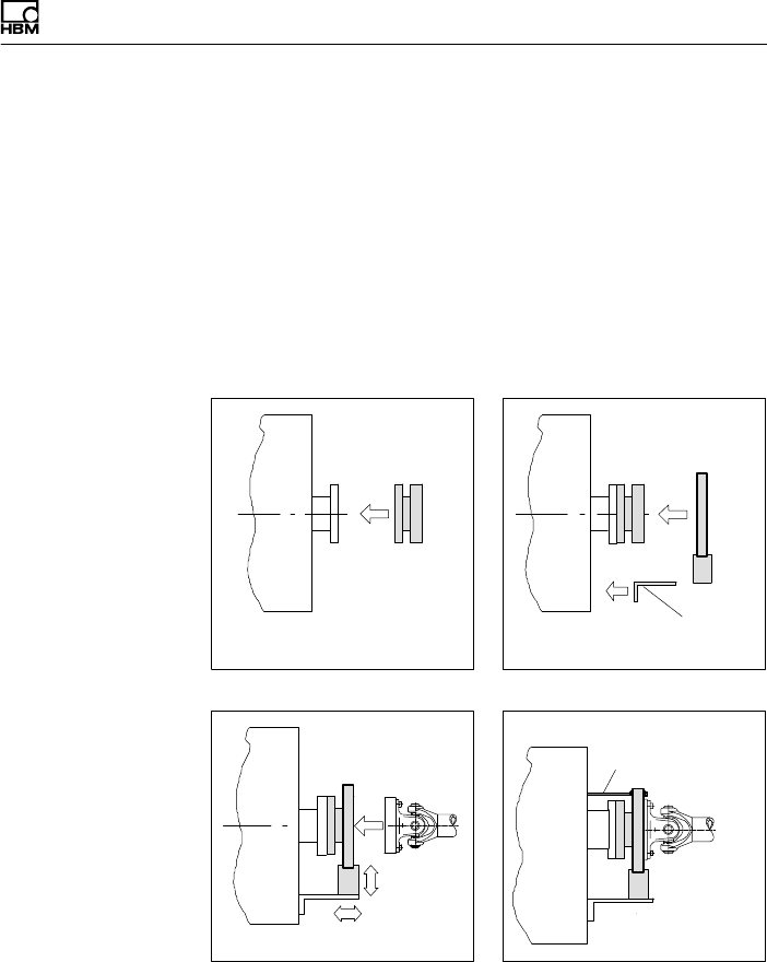
Mechanischer Einbau
T40B A3452-10.0 25
nicht möglich (z.B. bei nachträglichem Wechsel des Sta
tors), müssen Sie den Antennenring zerlegen (nur mög
lich für Option 7, Code S). Beachten Sie hierbei unbe
dingt die Hinweise zum Zusammenbau der
Antennensegmente (siehe Kapitel 5.4.2).
5.4.1 Einbau mit nicht demontiertem Antennenring,
Option 7, Code U mit
Antennen-Abschirmungsabdeckung
Kundenseitige
Befestigung
1. Rotor montieren 2. Stator montieren
3. Wellenstrang fertigmontieren 4. Abstützung montieren
Kundenseitige
Abstützung
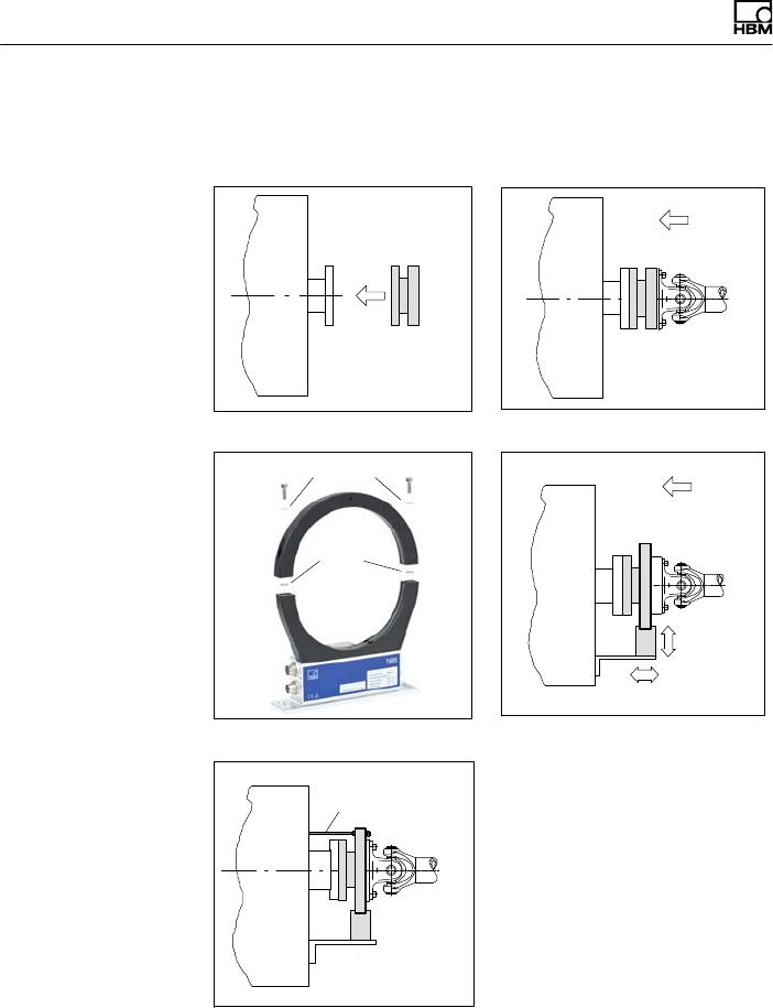
Mechanischer Einbau
26 A3452-10.0 T40B
5.4.2 Einbau mit nachträglicher Montage des
Stators, Option 7, Code S
Fächer
scheiben
Unterlegscheiben
1. Rotor montieren 2. Wellenstrang montieren
3. Antennensegment demontieren 4. Antennensegment montieren
Kundenseitige
Abstützung
5. Abstützung montieren
Mechanischer Einbau
T40B A3452-10.0 27
5.5 Montage des Rotors
Tipp
Nach der Montage ist in der Regel das Rotor‐Typenschild
verdeckt. Deshalb liegen dem Rotor zusätzliche Klebe
schilder mit den wichtigen Kenndaten bei, die Sie auf den
Stator oder andere relevante Prüfstandskomponenten
aufkleben können. Sie können dann jederzeit die für Sie
interessanten Daten ablesen, z.B. das Shuntsignal. Für
die eindeutige Zuordnung der Daten ist am Rotorflansch
von außen sichtbar eine Identifikationsnummer und die
Baugröße eingraviert.
Hinweis
Achten Sie darauf, dass während der Montage die in
Abb. 5.1 markierte Messzone nicht beschädigt wird, z.B.
durch Abstützen oder Anschlagen von Werkzeugen beim
Anziehen der Schrauben. Dies kann den Aufnehmer
beschädigen und damit zu Fehlmessungen führen oder
sogar zerstören.
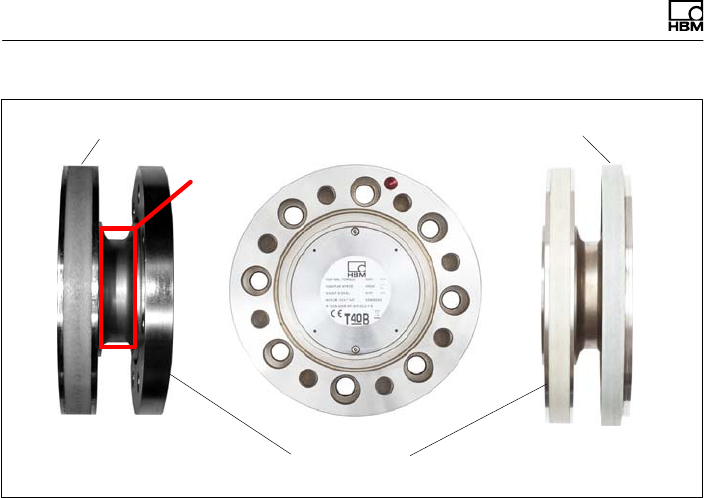
Mechanischer Einbau
28 A3452-10.0 T40B
ohne Drehzahl
messsystem mit Drehzahl
messsystem
Flanschplanflächen
Übertragerwicklung Drehzahlmesssystem
Messzone
Abb. 5.1 Verschraubung des Rotors
1. Reinigen Sie vor dem Einbau die Flanschplanflächen
des Aufnehmers und der Gegenflansche.
Die Flächen müssen für eine sichere Drehmoment
übertragung sauber und fettfrei sein. Benutzen Sie mit
Lösungsmittel angefeuchtete Lappen oder Papier.
Achten Sie beim Reinigen darauf, dass die Über
tragerwicklung oder das Drehzahlmesssystem nicht
beschädigt werden.
2. Verwenden Sie für die Verschraubung des Rotors
(siehe Abb. 5.1) sechs bzw. acht
Innensechskantschrauben DIN EN ISO 4762 der
Festigkeitsklasse nach Tab. 5.1 in geeigneter Länge
(abhängig von der Anschlussgeometrie, siehe
Tab. 5.1 auf Seite 30).
Wir empfehlen Zylinderschrauben DIN EN ISO4762,
geschwärzt, glatter Kopf, zulässige Maß‐ und For
Mechanischer Einbau
T40B A3452-10.0 29
mabweichung nach DIN ISO4759, Teil1, Produkt
klasse A.
3. Ziehen Sie alle Schrauben mit dem vorgeschriebenen
Drehmoment an (Tab. 5.1 auf Seite 30).
4. Am Rotor befinden sich zur weiteren Montage des
Wellenstranges sechs bzw. acht Gewindebohrungen.
Verwenden Sie ebenfalls Schrauben der Festigkeits
klasse 10.9 bzw. 12.9 und ziehen Sie diese mit dem
vorgeschriebenen Moment nach Tab. 5.1 an.
Wichtig
Kleben Sie die Verbindungsschrauben mit einer Schrau
bensicherung (mittelfest, z.B. von LOCTITE) in das Ge
gengewinde ein, um einen Vorspannverlust durch
Lockern auszuschließen, falls Wechsellasten zu erwarten
sind.
Hinweis
Halten Sie die maximale Einschraubtiefe nach Tab. 5.1
unbedingt ein. Andernfalls kann es zu erheblichen Mess
fehlern durch Drehmomentnebenschluss oder zur
Beschädigung des Aufnehmers kommen.
Mechanischer Einbau
30 A3452-10.0 T40B
Messbereich Befestigungsschrauben Vorgeschriebenes
Anzugsmoment
NVmZ 1Festigkeitsklasse NVm
50 M8
10.9
34
100 M8
200 M8
500 M10 67
1k M10 67
2k M12 115
3k M12
12.9
135
5k M14 220
10k M16 340
1) DIN EN ISO4762; schwarz/geölt/mges=0,125
Tab. 5.1 Befestigungsschrauben
Wichtig
Trockene Schraubenverbindungen können abweichende,
höhere Reibfaktoren zur Folge haben (siehe z.B.
VDI 2230). Dadurch ändern sich die erforderlichen
Anzugsmomente.
Die erforderlichen Anzugsmomente können sich auch
ändern, falls Sie Schrauben mit anderer Oberfläche oder
anderer Festigkeitsklasse als in Tab. 5.1 angegeben
verwenden, da dies den Reibfaktor beeinflusst.
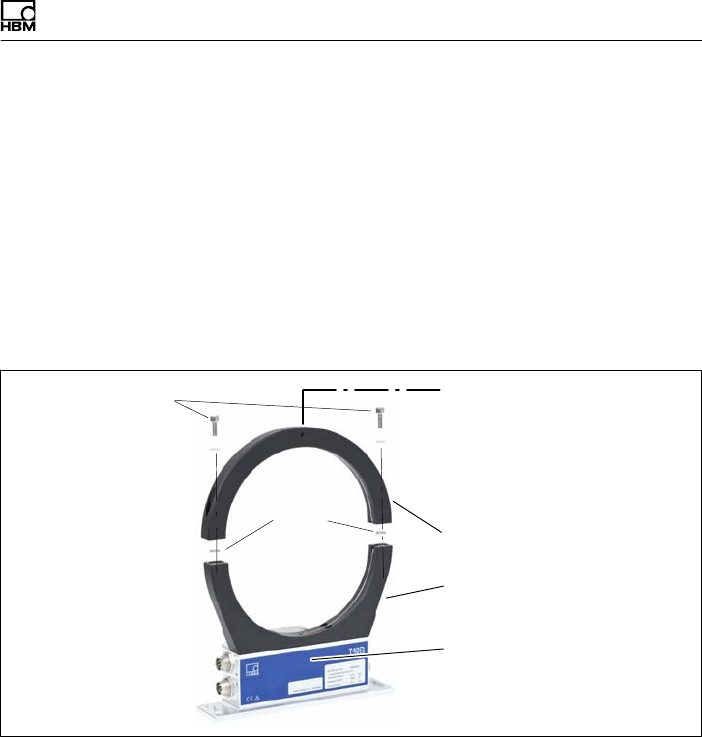
Mechanischer Einbau
T40B A3452-10.0 31
5.6 Montage des Stators
Im Anlieferungszustand ist der Stator betriebsfertig mon
tiert. Sie können das obere Antennensegment vom Sta
tor trennen, zum Beispiel bei Wartungsarbeiten, oder um
eine leichtere Montage des Stators zu ermöglichen, nur
für Option 7, Code S.
Ist in Ihrem Fall ein Zerlegen des Stators nicht nötig, ver
fahren Sie nach den Punkten 2., 5., und 6 für Option 7,
Code U.
Fächer
scheiben
Bohrung zur Fixierung des
Antennensegmentes,
Durchmesser 4,2 bzw. 5,2mm,
abhängig von der Nennlast
Statorgehäuse
oben
Antennensegment‐
Schrauben mit
Unterlegscheiben (M5)
unten
Antennensegmente
Abb. 5.2 Verschraubung der Antennensegmente am Stator,
Option 7, Code S
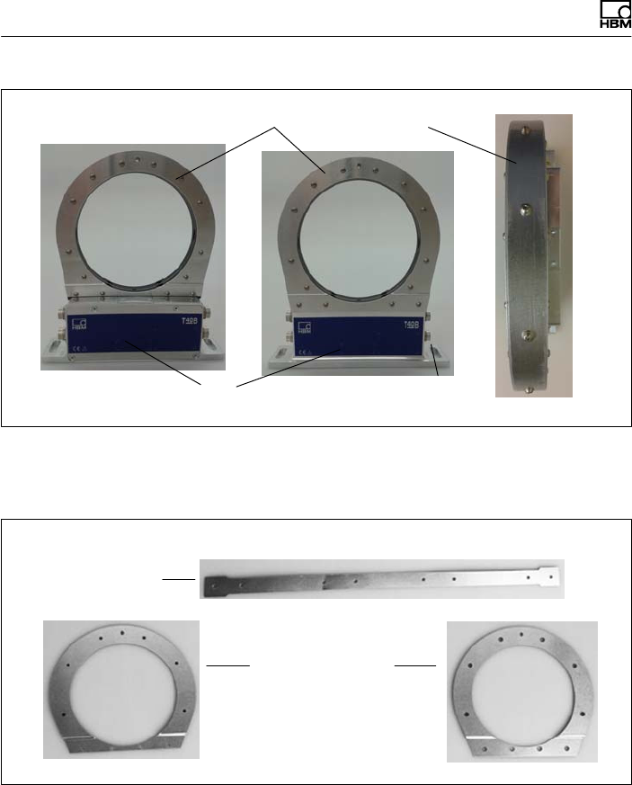
Mechanischer Einbau
32 A3452-10.0 T40B
Statorgehäuse
Antennensegmente mit montierten Abschirmungsplatten
Anschlüsse
Abb. 5.3 Mechanischer Aufbau des Stators mit montierten
Abschirmungsplatten ohne Drehzahlmesssystem,
Option 7, Code U
Abmontierte Abschirmungsplatten
Axiale
Abschirmungsplatten
Radiale
Abschirmungsplatte
Abb. 5.4 Einzelne Abschirmungsplatten, Option 7, Code U
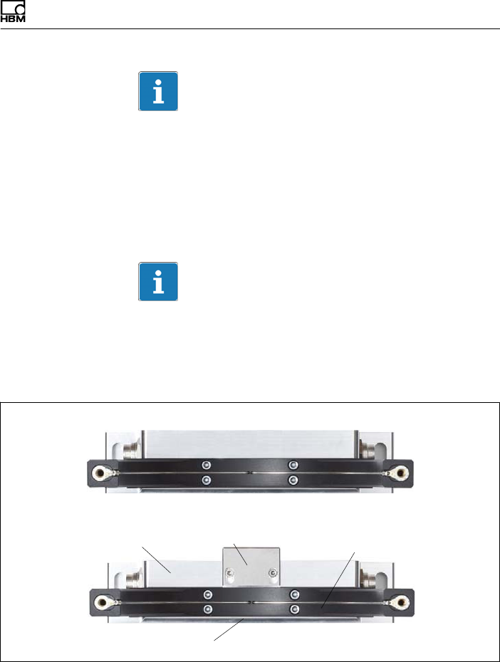
Mechanischer Einbau
T40B A3452-10.0 33
Wichtig
Um die Einhaltung der FCC-Vorschriften zu gewährleis
ten, müssen die Abschirmungsplatten unbedingt
verwendet werden. Müssen die Abschirmungsplatten zu
irgendeinem Zweck entfernt werden (z. B. zur Installation
oder Wartung), müssen sie in der ursprünglichen Position
wieder angebracht werden, bevor das Gerät in Betrieb
genommen wird.
Wichtig
Wenn die Abschirmungsplatten zu Installations- oder
Wartungszwecken entfernt werden müssen, müssen die
Schrauben bei der anschließenden Montage mit einem
Anzugsmoment von 0,6 Nm festgezogen werden.
Statorgehäuse
unteres Antennensegment
Antennendraht
T40B ohne Drehzahlmesssystem
T40B mit Drehzahlmesssystem
Sensorkopf für Drehzahlmessung
Abb. 5.5 Statorgehäuse und unteres Antennensegment mit
Antennendraht, Option 7, Code S
Mechanischer Einbau
34 A3452-10.0 T40B
1. Lösen und entfernen Sie die Verschraubungen (M5)
am oberen Antennensegment.
Zwischen den Antennensegmenten sind Fächerschei
ben angeordnet: Achten Sie darauf, dass diese nicht
verloren gehen.
2. Montieren Sie das Statorgehäuse auf einer geeigne
ten Grundplatte im Wellenstrang, sodass ausrei
chende Einstellmöglichkeiten in horizontaler und verti
kaler Richtung vorhanden sind. Ziehen Sie die
Schrauben aber noch nicht fest.
Tipp
Falls Ihr Aufnehmer einen Sensor für den Referenz
impuls besitzt, sollten Sie das obere Antennensegment
erst nach Schritt 5 montieren.
3. Montieren Sie nun das unter Punkt 1. entfernte obere
Antennensegment mit zwei Innensechskantschrauben
auf das untere Antennensegment.
Achten Sie darauf, dass zwischen den Antennenseg
menten die beiden Fächerscheiben eingelegt sind
(diese sorgen für einen definierten Übergangswider
stand)!
Wichtig
Um eine einwandfreie Funktion zu gewährleisten,
müssen die Fächerscheiben (A5,3‐FST DIN 6798 ZN/
verzinkt) nach dreimaligem Lösen der
Antennen‐Verschraubung erneuert werden.
4. Ziehen Sie nun alle Verschraubungen der Antennen
segmente mit einem Anzugsmoment von 5N⋅m an.
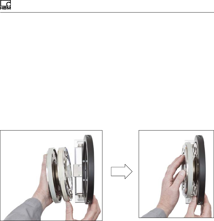
Mechanischer Einbau
T40B A3452-10.0 35
5. Drehzahlmessung ohne Sensor für Referenzimpuls
(Null‐Index):
Richten Sie die Antenne zum Rotor so aus, dass die
Antenne den Rotor etwa koaxial umschließt und der
Antennendraht in axialer Richtung die gleiche Position
wie die Mitte der Übertragerwicklung auf dem Rotor
aufweist.
Um die Ausrichtung zu erleichtern, haben das Anten
nensegment und der Wicklungsträger am Flansch B
die gleiche Breite. Beachten Sie bitte die in den tech
nischen Daten angegebenen zulässigen Ausrich
tungstoleranzen.
Abb. 5.6 Ausrichten des Rotors mit dem Stator (ohne
Referenzimpuls‐Sensor), Option 7, Code S und U
Drehzahlmessung mit Sensor für Referenzimpuls
(Null‐Index):
Halten Sie den Stator leicht schräg (siehe Abb. 5.7
links), sodass sich der Bügel mit dem Sensorkopf für
den Referenzimpuls (Null‐Index) zwischen den beiden
Flanschen befindet. Kippen Sie nun den Stator so
weit über den Rotor, bis der Antennenring den
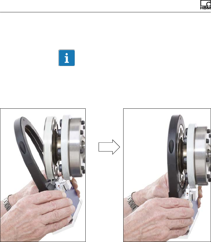
Mechanischer Einbau
36 A3452-10.0 T40B
Flansch mit der Übertragerwicklung vollständig
überdeckt (siehe Abb. 5.7 rechts).
Information
Falls der Statorfuß bereits fest installiert ist, müssen Sie
das obere Antennensegment entfernen (siehe Schritte 1,
3 und 4). Andernfalls können Sie die Montage wie in den
Bildern gezeigt vornehmen.
Abb. 5.7 Ausrichten des Rotors mit dem Stator (mit
Referenzimpuls‐Sensor), Option 7, Code S und U
6. Ziehen Sie jetzt die Verschraubung des Statorgehäu
ses fest an.

Mechanischer Einbau
T40B A3452-10.0 37
Vermeidung von Axialschwingungen des Stators
Je nach Betriebsbedingungen kann es vorkommen, dass
der Stator zum Schwingen angeregt wird. Dieser Effekt
ist abhängig von:
Sder Drehzahl,
Sdem Antennendurchmesser (abhängig vom Messbe
reich),
Sder Konstruktion des Maschinenbettes.
Wichtig
Um Axialschwingungen zu vermeiden, muss der Anten
nenring kundenseitig abgestützt werden. Hierzu befindet
sich am oberen Antennensegment eine Buchse (mit M5
Innengewinde), die zur Aufnahme einer entsprechenden
Klemmeinrichtung dienen kann (siehe Abb. 5.8).
Gleichzeitig ist in diesem Fall eine Abstützung der Kabel
stecker erforderlich, ein Konstruktionsbeispiel zeigt
Abb. 5.9.
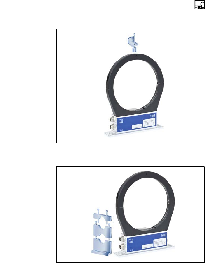
Mechanischer Einbau
38 A3452-10.0 T40B
Abb. 5.8 Konstruktionsbeispiel für die Abstützung des
Antennenrings, Option 7, Code S und U
Abb. 5.9 Konstruktionsbeispiel für Steckerklemmen (für zwei
Stecker), Option 7, Code S und U
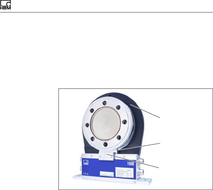
Mechanischer Einbau
T40B A3452-10.0 39
5.7 Drehzahlmesssystem, Referenzimpuls
(optional)
Das optionale Drehzahlmesssystem (auch mit der
zusätzlichen Option Referenzimpuls bzw. Null‐Index) ist
werksseitig bereits in den Aufnehmer integriert, es ist
keine Montage nötig.
Sensorkopf für
Drehzahlmessung
Magnetring für
Drehzahlmessung
Sensorkopf für
Referenzimpuls
Abb. 5.10 Drehmomentaufnehmer mit Drehzahlmessung und
Referenzimpuls, Option 7, Code S und U
Ausrichtung Sensorkopf des Drehzahlmesssystems
Bei exakter Ausrichtung des Stators zur Drehmoment
messung ist auch das Drehzahl‐Messsystem sowie der
Sensor für den Referenzimpuls (Null‐Index) richtig aus
gerichtet. Die beiden Inbus‐Schrauben am Sensorkopf
(Abb. 5.11) dürfen deshalb nicht gelöst werden.
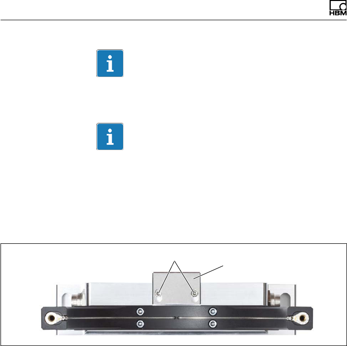
Mechanischer Einbau
40 A3452-10.0 T40B
Wichtig
Sie dürfen die Position des Sensorkopfes nicht
verändern.
Wichtig
Es handelt sich um ein magnetisches Drehzahlmesssys
tem. In Applikationen bei denen mit hohen magnetischen
Feldstärken zu rechnen ist (z.B. Wirbelstrombremse), ist
durch geeignete Maßnahmen dafür zu sorgen, dass die
max. magnetische Feldstärke gemäß Spezifikation nicht
überschritten wird.
Schrauben keinesfalls lösen!
Sensorkopf für
Drehzahlmessung
Abb. 5.11 Drehmomentaufnehmer mit Sensorkopf zur
Drehzahlmessung, Option 7, Code S und U
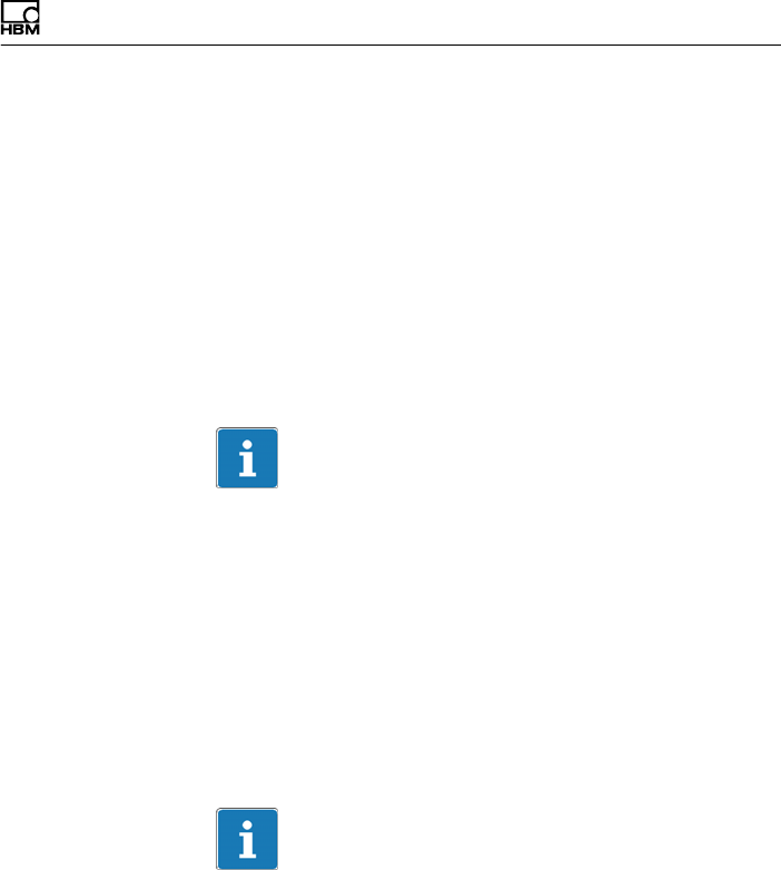
Elektrischer Anschluss
T40B A3452-10.0 41
6 Elektrischer Anschluss
6.1 Allgemeine Hinweise
SAchten Sie bei Kabelverlängerungen auf eine ein
wandfreie Verbindung mit geringstem Übergangs
widerstand und guter Isolation.
SAlle Kabel‐Steckverbindungen oder Überwurfmuttern
müssen fest angezogen werden.
Wichtig
Aufnehmer‐Anschlusskabel von HBM mit montierten
Steckern sind ihrem Verwendungszweck entsprechend
gekennzeichnet (Md oder n). Beim Kürzen der Kabel,
Einziehen in Kabelkanälen oder Verlegen in Schalt
schränken kann diese Kennzeichnung verloren gehen
oder verdeckt sein. Kennzeichnen Sie daher die Kabel in
diesen Fällen vor der Verlegung.
6.2 EMV‐Schutz
Wichtig
Die Aufnehmer sind gemäß EG‐Richtlinien EMV‐geprüft
und mit einer CE‐Zertifizierung gekennzeichnet. Sie
müssen jedoch den Schirm des Anschlusskabels am
schirmenden Gehäuse der Elektronik anschließen, um
den EMV‐Schutz der Messkette zu erreichen.

Elektrischer Anschluss
42 A3452-10.0 T40B
Die Signalübertragung zwischen Übertragerkopf und Ro
tor erfolgt rein digital und ist durch spezielle elektronische
Kodierungsverfahren gegen elektromagnetische Beein
flussungen geschützt.
Der Kabelschirm wird mit dem Aufnehmergehäuse ver
bunden. Dadurch ist das Messsystem (ohne Rotor) von
einem Faradayschen Käfig umschlossen, wenn die Schir
mung an beiden Kabelenden flächig aufgelegt wird.
Sehen Sie bei anderen Anschlusstechniken im Litzenbe
reich eine EMVfeste Abschirmung vor, bei der ebenfalls
die Schirmung flächig aufgelegt ist (siehe auch
HBMGreenlineInformation, Druckschrift i1577).
Elektrische und magnetische Felder verursachen oft eine
Einkopplung von Störspannungen in den Messkreis.
Deshalb:
SVerwenden Sie nur abgeschirmte, kapazitätsarme
Messkabel (HBM‐Kabel erfüllen diese Bedingungen).
SVerwenden Sie ausschließlich Stecker, die den
EMVRichtlinien entsprechen.
SLegen Sie die Messkabel nicht parallel zu Starkstrom‐
und Steuerleitungen. Falls das nicht möglich ist,
schützen Sie das Messkabel, z.B. durch Stahlpanzer
rohre.
SMeiden Sie Streufelder von Trafos, Motoren und
Schützen.
SErden Sie Aufnehmer, Verstärker und Anzeigegerät
nicht mehrfach.
SSchließen Sie alle Geräte der Messkette an den
gleichen Schutzleiter an.
SFalls Störungen durch Potenzialunterschiede (Aus
gleichsströme) auftreten, trennen Sie am Messver
stärker die Verbindungen zwischen Versorgungsspan
nungsnull und Gehäusemasse und legen Sie eine

Elektrischer Anschluss
T40B A3452-10.0 43
Potenzialausgleichsleitung zwischen Statorgehäuse
und Messverstärkergehäuse (Kupferleitung, mindes
tens 10mm2 Leitungsquerschnitt).
SSollten Potenzialunterschiede zwischen Rotor und
Stator der Maschine auftreten, z.B. durch unkontrol
liertes Ableiten, hilft meist das eindeutige Erden des
Rotors z.B. mittels Schleifer. Der Stator muss auf das
gleiche (Erd‐)Potenzial gelegt werden.
6.3 Steckerbelegung
Am Statorgehäuse befinden sich zwei 7‐polige Stecker,
ein 8‐poliger und ein 16‐poliger Stecker.
Die Anschlüsse der Versorgungsspannung und des
Shuntsignals der Stecker 1 und 3 sind jeweils mitein
ander galvanisch verbunden aber mit Dioden gegen Aus
gleichsströme geschützt. Die Anschlüsse der Versor
gungsspannung sind zusätzlich mit einer
selbstrückstellenden Sicherung (Multifuse) gegen
Überlast durch den Stator geschützt.
Hinweis
Die Drehmoment‐Messflansche sind nur für den Betrieb
mit DC‐Versorgungsspannung vorgesehen. Sie dürfen
nicht an ältere HBM‐Messverstärker mit Rechteck‐Spei
sung angeschlossen werden. Hier könnte es zur Zerstö
rung von Widerständen der Anschlussplatte bzw. ande
ren Fehlern in den Messverstärkern kommen.
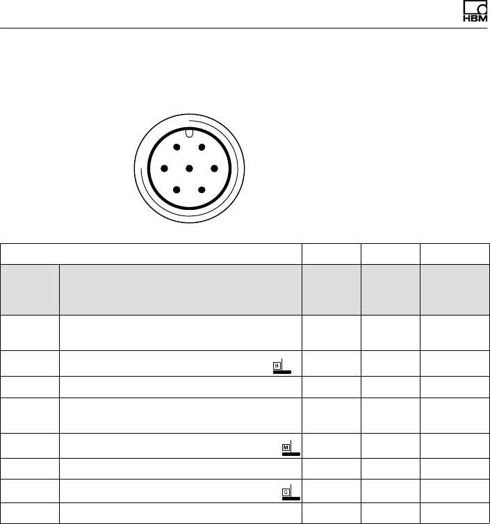
Elektrischer Anschluss
44 A3452-10.0 T40B
Belegung Stecker 1 - Versorgungsspannung und
Frequenz‐Ausgangssignal
61
572
43
Gerätestecker
Draufsicht
KAB153 KAB149 KAB1781)
Stecker
Pin
Belegung Ader
farbe
D‐SUB‐
Stecker
Pin
HD‐SUB‐
Stecker
Pin
1Messsignal Drehmoment
(Frequenzausgang; 5 V2,3)ws 13 5
2Versorgungsspannung 0 V sw 5 -
3Versorgungsspannung 18 V …30 V bl 6 -
4Messsignal Drehmoment
(Frequenzausgang; 5 V2,3)rt 12 10
5Messsignal 0 V; symmetrisch gr 8 6
6Shuntsignal‐Auslösung 5 V … 30 V gn 14 15
7Shuntsignal 0 V gr 8
Schirm an Gehäusemasse
1) Brücke zwischen 4 +9
2) Komplementäre Signale RS‐422; ab 10m Kabellänge empfehlen wir einen Abschlusswiderstand
mit R = 120Ohm zwischen den Adern (ws) und (rt).
3) RS‐422: Pin 1 entspricht A, Pin 4 entspricht B.
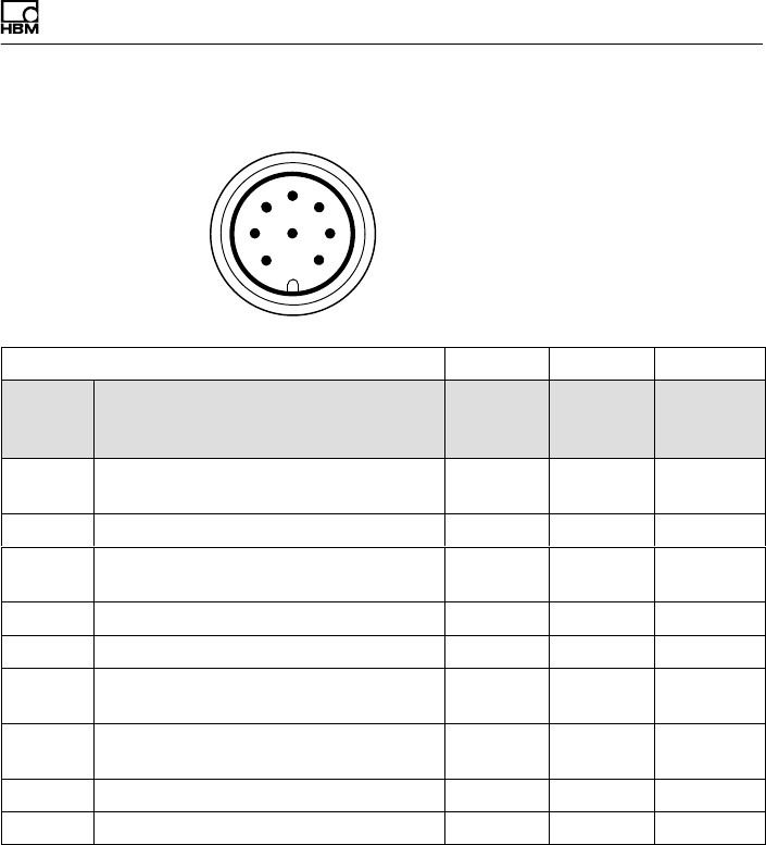
Elektrischer Anschluss
T40B A3452-10.0 45
Belegung Stecker 2 - Drehzahl-Messsystem
6
1
5
7
2
4
38
Gerätestecker
Draufsicht
KAB154 KAB150 KAB1791)
Stecker
Pin
Belegung Ader
farbe
D-SUB-
Stecker
Pin
HD-SUB-
Stecker
Pin
1Messsignal Drehzahl 2) (Impulsfolge,
5V; 0°)rt 12 10
2Nicht belegt bl - -
3Messsignal Drehzahl 2 (Impulsfolge,
5V; um 90° phasenverschoben) gr 15 8
4Nicht belegt sw - -
5Nicht belegt vi - -
6Messsignal Drehzahl 2)
(Impulsfolge, 5V; 0°)ws 13 5
7Messsignal Drehzahl 2) (Impulsfolge,
5V; um 90° phasenverschoben) gn 14 7
8 Betriebsspannungsnull sw/bl 3) 8 6
Schirm an Gehäusemasse
1) Brücke zwischen 4 + 9
2) Komplementäre Signale RS‐422; ab 10m Kabellänge empfehlen wir einen Abschlusswiderstand
mit R = 120Ohm.
3) Bei KAB163 / KAB164 Aderfarbe braun (bn)
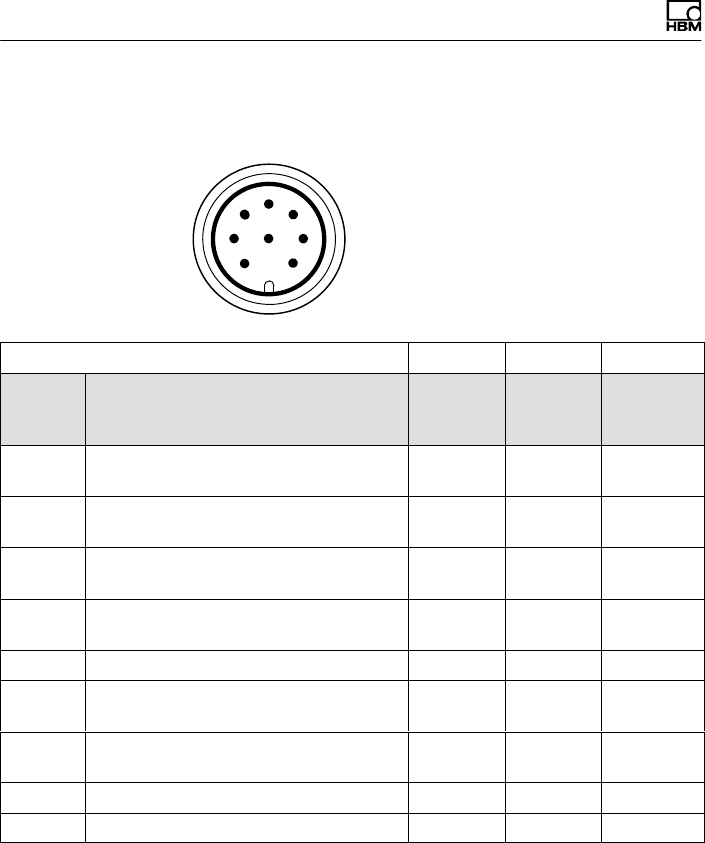
Elektrischer Anschluss
46 A3452-10.0 T40B
Belegung Stecker 2 - Drehzahl‐Messsystem mit
Referenzimpuls
6
1
5
7
2
4
38
Gerätestecker
Draufsicht
KAB164 KAB163 KAB1811)
Stecker
Pin
Belegung Ader
farbe
D-SUB-
Stecker
Pin
HD-SUB-
Stecker
Pin
1Messsignal Drehzahl 2) (Impulsfolge,
5V; 0°)rt 12 10
2Referenzsignal (1 Impuls/Umdrehung,
5V) 2) bl 2 3
3Messsignal Drehzahl 2) (Impulsfolge,
5V; um 90° phasenverschoben) gr 15 8
4Referenzsignal (1 Impuls/Umdrehung,
5V) 2) sw 3 2
5Nicht belegt vi - -
6Messsignal Drehzahl 2) (Impulsfolge,
5V; 0°)ws 13 5
7Messsignal Drehzahl 2) (Impulsfolge,
5V; um 90° phasenverschoben) gn 14 7
8 Betriebsspannungsnull sw 3) 8 6
Schirm an Gehäusemasse
1) Brücke zwischen 4 + 9
2) Komplementäre Signale RS‐422; ab 10m Kabellänge empfehlen wir einen Abschlusswiderstand
mit R = 120Ohm.
3) Bei KAB163 / KAB164 Aderfarbe braun (bn)

Elektrischer Anschluss
T40B A3452-10.0 47
Pin 1
Pin 6
Pin 3
Pin 7
Pin 2
Pin 4
Abb. 6.1 Drehzahlsignale an Stecker 2 (Drehzahl in
Pfeilrichtung)
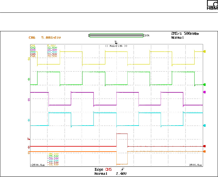
Elektrischer Anschluss
48 A3452-10.0 T40B
Pin 1
Pin 6
Pin 3
Pin 7
Pin 2
Pin 4
Abb. 6.2 Drehzahlsignale an Stecker 2 (Drehzahl gegen
Pfeilrichtung)
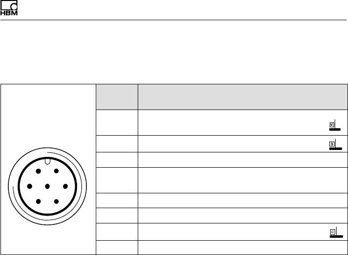
Elektrischer Anschluss
T40B A3452-10.0 49
Belegung Stecker 3 - Versorgungsspannung und
Spannungs‐Ausgangssignal
61
572
43
Gerätestecker
Draufsicht
Stecker
Pin
Belegung
1Messsignal Drehmoment
(Spannungsausgang; 0 V)
2Versorgungsspannung 0 V;
3Versorgungsspannung 18 V … 30 V DC
4Messsignal Drehmoment (Spannungsausgang,
±10 V)
5Nicht belegt
6Shuntsignal‐Auslösung 5 V … 30 V
7Shuntsignal 0 V;
Schirm an Gehäusemasse
Belegung Stecker 4
TMC - nur für HBM‐interne Verbindung zum Torque In
terface Module TIM 40/TIM-EC.
6.4 Versorgungsspannung
Der Aufnehmer wird mit einer Schutzkleinspannung
(Nenn‐Versorgungsspannung 18 … 30VDC) betrieben.
Sie können einen oder mehrere Drehmoment‐Messflan
sche innerhalb eines Prüfstandes gleichzeitig versorgen.
Treffen Sie zusätzliche Vorkehrungen für die Ableitung
von Überspannungen, falls Sie das Gerät an einem
Gleichspannungsnetz1) betreiben möchten.
1) Verteilsystem für elektrische Energie mit einer größeren räumlichen Ausdehnung (z. B. über
mehrere Prüfstände) das eventuell auch Verbraucher mit großen Nennströmen versorgt.
Elektrischer Anschluss
50 A3452-10.0 T40B
Die Hinweise dieses Kapitels beziehen sich auf den aut
arken Betrieb des T40B ohne HBM‐Systemlösungen.
Die Versorgungsspannung ist von den Signalausgängen
und den Shuntsignal‐Eingängen galvanisch getrennt.
Schließen Sie eine Schutzkleinspannung von 18V …
30V an Pin 3 (+) und Pin 2 ( ) der Stecker 1 oder 3 an.
Wir empfehlen, das HBM‐Kabel KAB 8/00‐2/2/2 und ent
sprechende Buchsen zu verwenden (siehe Zubehör).
Das Kabel darf bei Spannungen ≥24V bis zu 50m,
ansonsten bis zu 20m lang sein.
Wird die zulässige Kabellänge überschritten, können Sie
die Versorgungsspannung über zwei Anschlusskabel
(Stecker 1 und 3) parallel zuführen. Damit erreichen Sie
eine Verdoppelung der zulässigen Länge. Installieren Sie
andernfalls ein Netzteil vor Ort.
Wichtig
Im Einschaltmoment kann ein Strom von bis zu 4 A flie
ßen und damit Netzteile mit elektronischer Strombegren
zung ausschalten.
Shuntsignal
T40B A3452-10.0 51
7 Shuntsignal
Der Drehmoment‐Messflansch T40B liefert ein elektri
sches Shuntsignal, das bei Messketten mit HBM‐Kompo
nenten vom Verstärker aus aktiviert werden kann. Der
Aufnehmer erzeugt ein Shuntsignal von ca. 50 % des
Nenndrehmoments, der genaue Wert ist auf dem Typen
schild vermerkt. Stellen Sie nach der Aktivierung das
Verstärkerausgangssignal auf das Shuntsignal des ange
schlossenen Aufnehmers ein, ist der Messverstärker an
den Aufnehmer angepasst.
Information
Beim Messen des Shuntsignals sollte der Aufnehmer
unbelastet sein, da das Shuntsignal additiv aufgeschaltet
wird.
Auslösen des Shuntsignals
Durch Anlegen einer Schutzkleinspannung von 5 … 30V
an Pin 6 (+) und 7 ( ) am Stecker 1 oder 3 wird das
Shuntsignal ausgelöst.
Die Nennspannung für das Auslösen des Shuntsignals
beträgt 5V (Auslösen bei U > 2,5V), bei Spannungen
kleiner 0,7V ist der Aufnehmer im Messbetrieb. Die ma
ximal zulässige Spannung beträgt 30V, bei Nennspan
nung beträgt die Stromaufnahme ca. 2mA, bei Maximal
spannung ca. 18mA. Spannung für das Auslösen des
Shuntsignals ist galvanisch von der Versorgungs‐ und
der Messspannung getrennt.

Shuntsignal
52 A3452-10.0 T40B
Tipp
Bei HBM‐Systemlösungen kann das Shuntsignal vom
Messverstärker bzw. über die Bedien‐Software ausgelöst
werden.
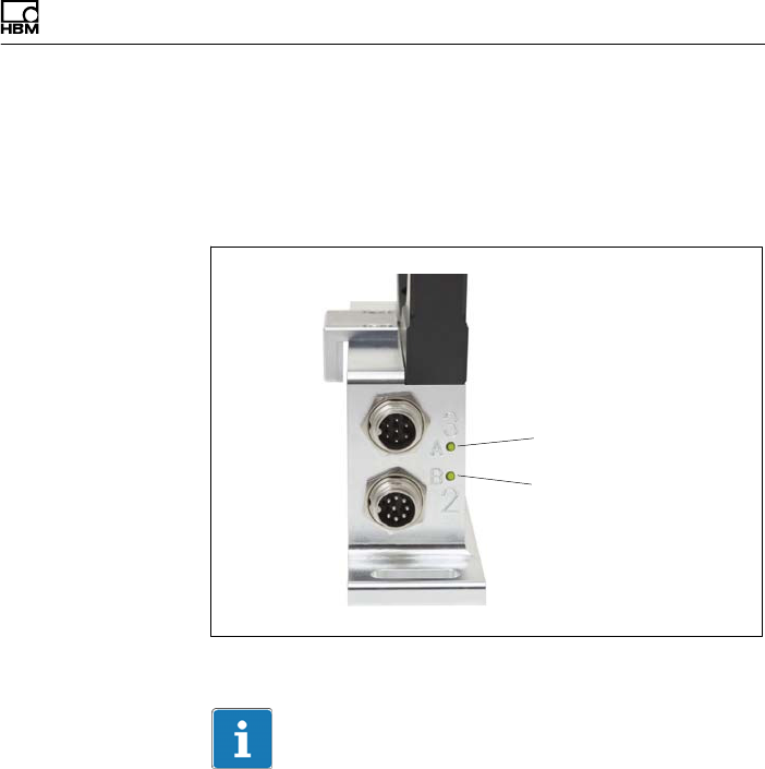
Funktionsprüfung
T40B A3452-10.0 53
8 Funktionsprüfung
Durch LEDs am Stator kann die Funktion von Rotor und
Stator überprüft werden.
LED A Rotorstatus
LED B Statorstatus
Abb. 8.1 LEDs am Statorgehäuse
Wichtig
Der Drehmomentaufnehmer benötigt nach Anlegen der
Versorgungsspannung noch bis zu 4 Sekunden, bevor er
betriebsbereit ist.

Funktionsprüfung
54 A3452-10.0 T40B
8.1 Rotorstatus, LED A (obere LED)
Farbe Bedeutung
Grün (pulsierend) Interne Rotor‐Spannungswerte o.k.
Orange blinkend
Fehljustierung von Rotor und Stator (zunehmende Blinkfre
quenz zeigt den Grad der Dejustierung an)
=> Ausrichtung Rotor-Stator korrigieren
Orange pulsierend
Rotorzustand nicht bestimmbar
=> Ausrichtung Rotor-Stator korrigieren
Falls die LED daraufhin immer noch orange pulsiert, liegt
möglicherweise ein Hardwaredefekt vor. Die Messignale neh
men den Pegel des Fehlerzustands an.
Rot (pulsierend)
Rotor‐Spannungswerte nicht in Ordnung.
=> Ausrichtung Rotor-Stator korrigieren
Falls die LED daraufhin immer noch rot pulsiert, liegt mögli
cherweise ein Hardwaredefekt vor. Die Messsignale nehmen
den Pegel des Fehlerzustands an.
Pulsierend bedeutet, die LED wird pro Sekunde für ca.
20ms dunkel geschaltet (Lebendsignal); damit ist das
Funktionieren des Aufnehmers erkennbar.
8.2 Statorstatus, LED B (untere LED)
Farbe Bedeutung
Grün
(dauerhaft leuchtend) Messsignal‐Übertragung und interne Stator‐Spannungen o.k.
Grün, zeitweise
orange.
Bei vielen Synchroni
sationsfehlern:
dauerhaft orange
Bei fehlerhafter Übertragung von y5 Messwerten in Folge bis
zum Ende der fehlerhaften Übertragung orange. Die Messsi
gnale nehmen für die Dauer des Übertragungsfehlers + ca.
weitere 3,3ms den Pegel des Fehlerzustands an.

Funktionsprüfung
T40B A3452-10.0 55
BedeutungFarbe
Orange
(dauerhaft leuch
tend)
Dauerhaft gestörte Übertragung, die Messignale nehmen
den Pegel des Fehlerzustands an. (fout = 0 Hz, Uout = Feh
lerlevel).
=> Ausrichtung Rotor-Stator korrigieren.
Rot
(dauerhaft leuch
tend)
Interner Statorfehler, die Messsignale nehmen den Pegel
des Fehlerzustands an (fout = 0 Hz, Uout = Fehlerlevel).

Belastbarkeit
56 A3452-10.0 T40B
9 Belastbarkeit
Das Nenndrehmoment darf statisch bis zum Grenzdreh
moment überschritten werden. Wird das Nenndrehmo
ment überschritten, sind weitere irreguläre Belastungen
nicht zulässig. Hierzu zählen Längskräfte, Querkräfte und
Biegemomente. Die Grenzwerte finden Sie im Kapitel 13
„Technische Daten“ auf Seite 61.
Messen dynamischer Drehmomente
Der Drehmoment‐Messflansch eignet sich zum Messen
statischer und dynamischer Drehmomente. Beim Messen
dynamischer Drehmomente ist zu beachten:
SDie für statische Messungen durchgeführte Kalibrie
rung des T40B gilt auch für dynamische Drehmoment
messungen.
SDie Eigenfrequenz f0 der mechanischen Messanord
nung hängt von den Trägheitsmomenten J1 und J2
der angeschlossenen Drehmassen sowie der Dreh
steifigkeit des T40B ab.
Die Eigenfrequenz f0 der mechanischen Messanordnung
lässt sich aus folgender Gleichung überschlägig
bestimmen:
f0+1
2p· cT·ǒ1
J1
)1
J2Ǔ
Ǹf0= Eigenfrequenz in Hz
J1, J2= Massenträgheitsmoment in kgVm2
cT= Drehsteifigkeit in NVm/rad
SDie zulässige mechanische Schwingbreite (Spitze-
Spitze) finden Sie ebenfalls in den technischen Daten.
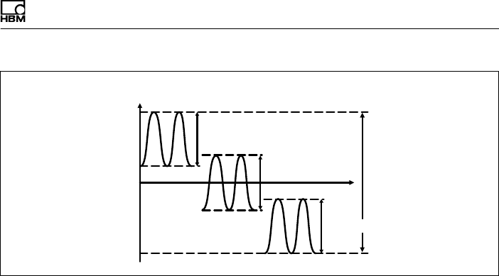
Wartung
T40B A3452-10.0 57
0
+Mnom
200 % Schwingbreite
-Mnom
Nenndrehmoment Mnom in %
Zeit t
Schwingbreite
Schwingbreite
Schwingbreite
Abb. 9.1 Zulässige dynamische Belastung
10 Wartung
Die Drehmoment‐Messflansche T40B sind wartungsfrei.
Entsorgung und Umweltschutz
58 A3452-10.0 T40B
11 Entsorgung und Umweltschutz
Alle elektrischen und elektronischen Produkte müssen
als Sondermüll entsorgt werden. Die ordnungsgemäße
Entsorgung von Altgeräten beugt Umweltschäden und
Gesundheitsgefahren vor.
Gesetzlich vorgeschriebene Kennzeichnung zur
Entsorgung
Elektrische und elektronische Geräte, die dieses Symbol
tragen, unterliegen der europäischen Richtlinie
2002/96/EG über elektrische und elektronische Altgeräte.
Das Symbol weist darauf hin, dass nicht mehr ge
brauchsfähige Altgeräte gemäß den europäischen Vor
schriften für Umweltschutz und Rohstoffrückgewinnung
getrennt von regulärem Hausmüll zu entsorgen sind.
Da die Entsorgungsvorschriften von Land zu Land unter
schiedlich sind, bitten wir Sie, im Bedarfsfall Ihren Liefe
ranten anzusprechen, welche Art von Entsorgung oder
Recycling in Ihrem Land vorgeschrieben ist.
Verpackungen
Die Originalverpackung der HBM‐Geräte besteht aus
recyclebarem Material und kann der Wiederverwertung
zugeführt werden. Bewahren Sie die Verpackung jedoch
mindestens für den Zeitraum der Gewährleistung auf. Bei
Reklamationen muss der Drehmoment‐Messflansch in
der Originalverpackung zurückgesandt werden.
Aus ökologischen Gründen sollte auf den Rücktransport
der leeren Verpackungen an uns verzichtet werden.
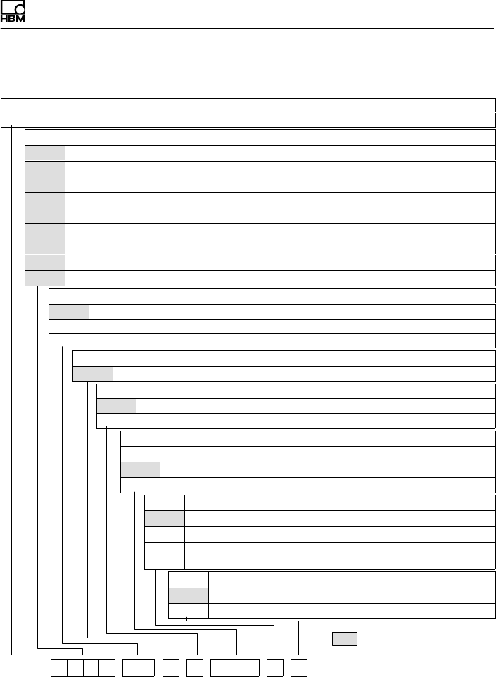
= VORZUGSTYPEN
Entsorgung und Umweltschutz
T40B A3452-10.0 59
12 Bestellnummern, Zubehör
Bestell‐Nr.
K-T40B [nur mit Option 2 = MF / ST]
Code Option 1: Messbereich bis
050Q 50 N·m [nur mit Option 2 = MF / RO]
100Q 100 N·m [nur mit Option 2 = MF / RO]
200Q 200 N·m [nur mit Option 2 = MF / RO]
500Q 500 N·m [nur mit Option 2 = MF / RO]
001R 1 kN·m [nur mit Option 2 = MF / RO]
002R 2 kN·m [nur mit Option 2 = MF / RO]
003R 3 kN·m [nur mit Option 2 = MF / RO]
005R 4 kN·m [nur mit Option 2 = MF / RO]
010R 5 kN·m [nur mit Option 2 = MF / RO]
Code Option 2: Komponente
MF Messflansch komplett
RO Rotor
ST Stator
Code Option 3: Genauigkeit
SStandard
Code Option 4: Nenndrehzahl
MStandard Drehzahl
HHohe Drehzahl
Code Option 5: Elektrische Konfiguration [nur mit Option 2 = MF / RO]
SU2 Ausg.sign. 10 kHz ±5 kHz und ±10 V, Versorg.sp. 18…30V DC
DU2 Ausg.sign. 60 kHz ±30 kHz und ±10 V, Versorg.sp. 18…30V DC
HU2 Ausg.sign. 240 kHz ±120 kHz u. ±10 V, Versorg.sp. 18…30V DC
Code Option 6: Drehzahlmesssystem
0Ohne Drehzahlmesssystem
1Magnetisches Drehzahlmesssystem: 1024 Impulse/Umdreh.
AMagnetisches Drehzahlmesssystem (1024 Impulse/Umdreh.)
und Referenzimpuls
Code Option 7: Kundenspezifische Modifikation
SKeine kundenspezifische Modifikation
UUS- und Canada-Version
K-T40B - 0 0 1 R - M F - S - M - D U 2 - 0 - S

Entsorgung und Umweltschutz
60 A3452-10.0 T40B
Zubehör, zusätzlich zu beziehen
Artikel Bestell‐Nr.
Anschlusskabel, konfektioniert
Anschlusskabel Drehmoment, Binder 423 - 15‐polig D‐Sub, 6m 1-KAB149-6
Anschlusskabel Drehmoment, Binder 423 - 7‐polig, freie Enden, 6m 1-KAB153-6
Anschlusskabel Drehzahl, Binder 423 - 15‐polig D‐Sub, 6m 1-KAB150-6
Anschlusskabel Drehzahl, Binder 423 - 8‐polig, freie Enden, 6m 1-KAB154-6
Anschlusskabel Drehzahl, Referenzimpuls, Binder 423 - 15‐polig
D‐Sub, 6m
1-KAB163-6
Anschlusskabel Drehzahl, Referenzimpuls, Binder 423 - 8‐polig, freie
Enden, 6m
1-KAB164-6
Anschlusskabel TMC, Binder 423 - 16‐polig, freie Enden, 6m 1-KAB174-6
Kabelbuchsen
423G-7S, 7‐polig (gerade) 3-3101.0247
423W-7S, 7‐polig (Winkel) 3-3312.0281
423G-8S, 8‐polig (gerade) 3-3312.0120
423W-8S, 8‐polig (Winkel) 3-3312.0282
Anschlusskabel, Meterware (Mindestbestellmenge: 10 m, Preis pro Meter)
Kab8/00-2/2/2 4-3301.0071
Technische Daten
T40B A3452-10.0 61
13 Technische Daten
13.1 Nenndrehmoment 50N·m bis 500N·m
Genauigkeitsklasse 0,1 0,05
Drehmoment‐Messsystem
Nenndrehmoment Mnom NVm 50 100 200 500
Nenndrehzahl min-1 20000
Nenndrehzahl, optional min-1 24000 22000
Linearitätsabweichung einschließ
lich Hysterese,
bezogen auf den Nennkennwert
Frequenzausgang
Für ein max. Drehmoment im Bereich:
Zwischen 0% v. Mnom und 20% v.
Mnom
% <±0,01
> 20% v. Mnom und 60% v. Mnom % <±0,02
> 60% v. Mnom und 100% v. Mnom % <±0,03
Spannungsausgang
Für ein max. Drehmoment im Bereich:
Zwischen 0% v. Mnom und 20% v.
Mnom
% <±0,01
> 20% v. Mnom und 60% v. Mnom % <±0,02
> 60% v. Mnom und 100% v. Mnom % <±0,03
Rel. Standardabweichung der
Wiederholbarkeit,
nach DIN1319, bezogen auf die
Ausgangssignaländerung
Frequenzausgang % <±0,03
Spannungsausgang % <±0,03

Technische Daten
62 A3452-10.0 T40B
Nenndrehmoment Mnom 50020010050NVm
Temperatureinfluss pro 10 K im
Nenntemperaturbereich
auf das Ausgangssignal, bezogen auf
den Istwert der Signalspanne
Frequenzausgang % ±0,1 ±0,05
Spannungsausgang % ±0,4 ±0,2
auf das Nullsignal, bezogen auf den
Nennkennwert
Frequenzausgang % ±0,1 ±0,05
Spannungsausgang % ±0,2 ±0,1
Nennkennwert
(Spanne zwischen Drehmoment = Null
und Nenndrehmoment)
Frequenzausgang 10kHz / 60kHz /
240kHz
kHz 5/30/120
Spannungsausgang V 10
Kennwerttoleranz
(Abweichung der tatsächlichen Aus
gangsgröße bei Mnom vom Nennkenn
wert)
Frequenzausgang % ±0,1
Spannungsausgang % ±0,1
Ausgangssignal bei
Drehmoment = Null
Frequenzausgang kHz 10/60/240
Spannungsausgang V 0

Technische Daten
T40B A3452-10.0 63
Nenndrehmoment Mnom 50020010050NVm
Nennausgangssignal
Frequenzausgang
bei positivem Nenndrehmoment kHz 15 1) / 90 2) / 360 3)
(5 V symmetrisch 4))
bei negativem Nenndrehmoment kHz 5 1) / 30 2) / 120 3)
(5 V symmetrisch 4))
Spannungsausgang
bei positivem Nenndrehmoment V +10
bei negativem Nenndrehmoment V -10
Lastwiderstand
Frequenzausgang kΩ ≥ 2
Spannungsausgang kΩ ≥ 10
Langzeitdrift über 48h bei Referenz
temperatur
Frequenzausgang % t±0,06 t±0,03
Spannungsausgang % t±0,06 t±0,03
Messfrequenzbereich, -3dB kHz 11) / 32) / 63)
Gruppenlaufzeit µst4001) / t2202) / t1503)
Restwelligkeit
Spannungsausgang 5) mV t40
Maximaler Aussteuerbereich 6)
Frequenzausgang kHz 2,5 … 17,5 1) / 15 … 105 2) /
60 … 420 3)
Spannungsausgang V -12 … +12
Energieversorgung
Nennversorgungsspannung
(Schutzkleinspannung DC)
V18 … 30
Stromaufnahme im Messbetrieb A< 1
Stromaufnahme im Anlaufbetrieb A< 4 (typ. 2) 50 μs
Nennaufnahmeleistung W < 10

Technische Daten
64 A3452-10.0 T40B
Nenndrehmoment Mnom 50020010050NVm
Maximale Kabellänge m 50
Shuntsignal ca. 50 % von Mnom
Toleranz des Shuntsignals, bezo
gen auf Mnom
% <±0,05
Nennauslösespannung V 5
Grenzauslösespannung V 36
Shuntsignal ein Vmin. >2,5
Shuntsignal aus Vmax. <0,7
Drehzahl‐Messsystem
Messsystem Magnetisch, mittels AMR‐Sensor
(Anisotropischer‐Resistiver‐Effekt)
und magnetisiertem Kunststoffring
auf abgedecktem Stahlring
Magnetische Pole 72 86
Maximale Lageabweichung der Pole 50 Winkelsekunden
Ausgangssignal V5V symmetrisch (RS‐422);
2 Rechtecksignale um ca. 90°
phasenverschoben
Impulse pro Umdrehung 1024
Mindestdrehzahl für ausreichende
Impulsstabilität
min-1 0
Impulstoleranz 7) Grad <±0,05
Maximal zulässige
Ausgangsfrequenz
kHz 420
Gruppenlaufzeit µs <150
Radialer Nennabstand zwischen
Sensorkopf und Magnetring
(mechanischer Abstand)
mm 1,6
Arbeitsbereich des Abstands
zwischen Sensorkopf und
Magnetring
mm 0,4 … 2,5

Technische Daten
T40B A3452-10.0 65
Nenndrehmoment Mnom 50020010050NVm
Max. zulässige Axialverschiebung
des Rotors gegenüber dem Stator 8)
mm ±1,5
Hysterese der
Drehrichtungsumkehr bei
Relativschwingungen zwischen
Rotor und Stator
Drehschwingungen des Rotors Grad < ca. 0,2
Horizontale Schwingwege des Stators mm < ca. 0,5
Magnetische Belastungsgrenze
Remanenzflussdichte mT >100
Koerzitivfeldstärke kA/m >100
Zulässige magnetische Feldstärke
für Signalabweichungen
kA/m <0,1
Lastwiderstand 9) kΩ≥2
Referenzimpuls‐Messsystem (0-Index)
Messsystem Magnetisch, mittels Hall‐Sensor
und Magnet
Ausgangssignal V5V symmetrisch (RS‐422)
Impulse pro Umdrehung 1
Mindestdrehzahl für ausreichende
Impulsstabilität
min-1 2
Impulsbreite, ca. Grad 0,088
Impulstoleranz 7) Grad <±0,05
Gruppenlaufzeit µs <150
Axialer Nennabstand zwischen
Sensorkopf und Magnetring
(mechanischer Abstand)
mm 2,0
Arbeitsbereich des Abstands
zwischen Sensorkopf und
Magnetring
mm 0,4 … 2,5

Technische Daten
66 A3452-10.0 T40B
Nenndrehmoment Mnom 50020010050NVm
Max. zulässige Axialverschiebung
des Rotors gegenüber dem Stator 8)
mm ±1,5
Allgemeine Angaben
EMV
Emission (nach FCC 7, Teil 15, Unter
abteilung C) 10)
-
Emission
(nach EN61326‐1, Abschnitt 7)
Funkstörfeldstärke 11)
-
Klasse B
Störfestigkeit (EN61326‐1, Tab. 2)
Elektromagnetisches Feld (AM) V/m 10
Magnetisches Feld A/m 100
Elektrostatische Entladungen (ESD)
Kontaktentladung kV 4
Luftentladung kV 8
Schnelle Transienten (Burst) kV 1
Stoßspannungen (Surge) kV 1
Leitungsgebundene Störungen (AM) V 10
Schutzart nach EN60529 IP 54
Referenztemperatur °C23
Nenntemperaturbereich °C+10 … +70
Gebrauchstemperaturbereich 12) °C-20 … +85
Lagerungstemperaturbereich °C-40 … +85
Mechanischer Schock nach
EN60068‐2‐2713)
Anzahl n 1000
Dauer ms 3
Beschleunigung (Halbsinus) m/s2650
Schwingbeanspruchung in drei
Richtungen nach EN60068‐2‐6 13)

Technische Daten
T40B A3452-10.0 67
Nenndrehmoment Mnom 50020010050NVm
Frequenzbereich Hz 10 … 2000
Dauer h 2,5
Beschleunigung (Amplitude) m/s2200
Belastungsgrenzen 14)
Grenzdrehmoment, bez. auf Mnom 15) % 400 200
Bruchdrehmoment, bez. auf Mnom 15) % 800 > 400
Grenzlängskraft 16) kN 5 5 10 13
Grenzquerkraft 16) kN 1 1 2 4
Grenzbiegemoment 16) N⋅m 50 50 100 200
Schwingbreite nach DIN50100
(Spitze/Spitze) 17)
N⋅m 200 200 400 1000
Mechanische Werte
Drehsteifigkeit cTkN⋅m/rad 180 180 360 745
Verdrehwinkel bei Mnom Grad 0,016 0,032 0,032 0,038
Steifigkeit in axialer Richtung cakN/mm 285 285 540 450
Steifigkeit in radialer Richtung crkN/mm 160 160 315 560
Steifigkeit bei Biegemoment um
eine radiale Achse cb
kN⋅m/
Grad
1,9 1,9 3,6 4,2
Maximale Auslenkung bei Grenz
längskraft
mm <0,04 <0,05
Zusätzlicher max. Rundlauffehler
bei Grenzquerkraft
mm <0,02
Zusätzliche Planparallelitäts
abweichung bei Grenzbiegemoment
(bei j dB)
mm <0,06 <0,11
Auswucht‐Gütestufe nach
DIN ISO 1940
G 2,5
Technische Daten
68 A3452-10.0 T40B
Nenndrehmoment Mnom 50020010050NVm
Zul. max. Schwingweg des Rotors
(Spitze-Spitze) 18)
Wellenschwingungen im Bereich der
Anschlussflansche in Anlehnung an
ISO7919‐3
Normalbetrieb (Dauerbetrieb) µms(p*p) +9000
n
Ǹ(n in min-1)
Start‐ und Stoppbetrieb/Resonanz
bereiche (temporär)
µms(p*p) +13200
n
Ǹ(n in min-1)
Massenträgheitsmoment des
Rotors Jv
ohne Drehzahlmesssystem kg⋅m20,0010 0,0010 0,0017 0,0039
mit magn. Drehzahlmesssystem kg⋅m20,0015 0,0015 0,0022 0,0048
Anteiliges Massenträgheitsmoment
für Übertragerseite (Seite des
Flansches mit Außenzentrierung)
ohne Drehzahlmesssystem % v. Jv68 68 62 59
mit magn. Drehzahlmesssystem % v. Jv44 44 48 48
Zulässige max. statische
Exzentrizität
des Rotors (radial) zum Statormittel
punkt
ohne Drehzahlmesssystem mm ±2
Zulässiger axialer Verschiebeweg
zwischen Rotor und Stator 19)
ohne Drehzahlmesssystem mm ±2

Technische Daten
T40B A3452-10.0 69
Nenndrehmoment Mnom 50020010050NVm
Gewicht
Rotor ohne Drehzahlmesssystem kg 0,7 0,7 1,1 1,9
Rotor mit magn. Drehzahlmesssystem kg 0,8 0,8 1,3 2,1
Stator kg 1,1 1,1 1,1 1,1
1) Option 5, 10 ±5 kHz (Code SU2)
2) Option 5, 60 ±30 kHz (Code DU2)
3) Option 5, 240 ±120 kHz (Code HU2)
4) Komplementäre Signale RS‐422, Abschlusswiderstand beachten.
5) Signalfrequenzbereich 0,1 bis 10kHz
6) Ausgangssignalbereich, in dem ein wiederholbarer Zusammenhang zwischen Drehmoment und
Ausgangssignal besteht.
7) Bei Nennbedingungen.
8) Die Angabe bezieht sich auf eine mittig axiale Ausrichtung. Abweichungen davon führen zu einer
veränderten Impulstoleranz.
9) Beachten Sie die gemäß RS‐422 nötigen Abschlusswiderstände.
10) Option 7, Code U
11) Option 7, Code S
12) Ab 70°C ist eine Wärmeableitung über die Bodenplatte des Stators erforderlich. Die Temperatur
der Bodenplatte darf 85°C nicht überschreiten.
13) Fixierung von Antennenring und Anschlussstecker erforderlich.
14) Jede irreguläre Beanspruchung (Biegemoment, Quer‐ oder Längskraft, Überschreiten des
Nenndrehmoments) ist bis zu der angegebenen Belastungsgrenze nur dann zulässig, solange
keine der jeweils anderen von ihnen auftreten kann. Andernfalls sind die Grenzwerte zu
reduzieren. Wenn je 30 % des Grenzbiegemoments und der Grenzquerkraft vorkommen, sind nur
noch 40 % der Grenzlängskraft zulässig, wobei das Nenndrehmoment nicht überschritten werden
darf. Die Auswirkungen der zulässigen Biegemomente, Längs‐ und Querkräfte auf das
Messergebnis sind v±0,3% (50Nm: ≤±0,6%) des Nenndrehmomentes. Die Belastungsgrenzen
gelten nur für den Nenntemperaturbereich. Bei Temperaturen <10_C sind die Belastungsgrenzen
um ca. 30% zu reduzieren (Zähigkeitsreduzierung).
15) Bei statischer Belastung.
16) Statisch und dynamisch.
17) Das Nenndrehmoment darf nicht überschritten werden.
18) Beeinflussung der Schwingungsmessungen durch Rundlauffehler, Schlag, Formfehler, Kerben,
Riefen, örtlichen Restmagnetismus, Gefügeunterschiede oder Werkstoffanomalien sind zu
berücksichtigen und von der eigentlichen Wellenschwingung zu trennen.
19) Oberhalb des Nenntemperaturbereiches: ±1,5mm.

Technische Daten
70 A3452-10.0 T40B
13.2 Nenndrehmoment 1kN·m bis 10kN·m
Genauigkeitsklasse 0,05
Drehmoment‐Messsystem
Nenndrehmoment Mnom kNVm 1 2 3 5 10
Nenndrehzahl U/min 20000 15000 12000 10000
Nenndrehzahl, optional U/min 22000 16000 14000 12000
Linearitätsabweichung ein
schließlich Hysterese, bezo
gen auf den Nennkennwert
Frequenzausgang
Für ein max. Drehmoment im
Bereich:
Zwischen 0% v. Mnom und
20% v. Mnom
% <±0,01
> 20% v. Mnom und 60% v.
Mnom
% <±0,02
> 60% v. Mnom und 100% v.
Mnom
% <±0,03
Spannungsausgang
Für ein max. Drehmoment im
Bereich:
Zwischen 0% v. Mnom und
20% v. Mnom
% <±0,01
> 20% v. Mnom und 60% v.
Mnom
% <±0,02
> 60% v. Mnom und 100% v.
Mnom
% <±0,03
Rel. Standardabweichung der
Wiederholbarkeit,
nach DIN1319, bezogen auf
die Ausgangssignaländerung
Frequenzausgang % <±0,03
Spannungsausgang % <±0,03

Technische Daten
T40B A3452-10.0 71
Nenndrehmoment Mnom 105321kNVm
Temperatureinfluss pro 10 K
im Nenntemperaturbereich
auf das Ausgangssignal, bezo
gen auf den Istwert der Signal
spanne
Frequenzausgang % ±0,05
Spannungsausgang % ±0,2
auf das Nullsignal, bezogen auf
den Nennkennwert
Frequenzausgang % ±0,05
Spannungsausgang % "0,1
Nennkennwert
(Spanne zwischen Dreh
moment = Null und Nenndreh
moment)
Frequenzausgang 10kHz /
60kHz / 240kHz
kHz 5/30/120
Spannungsausgang V 10
Kennwerttoleranz
(Abweichung der tatsächlichen
Ausgangsgröße bei Mnom vom
Nennkennwert)
Frequenzausgang
Spannungsausgang
%
%
±0,1
±0,1
Ausgangssignal bei
Drehmoment = Null
Frequenzausgang kHz 10/60/240
Spannungsausgang V 0

Technische Daten
72 A3452-10.0 T40B
Nenndrehmoment Mnom 105321kNVm
Nennausgangssignal
Frequenzausgang
bei positivem
Nenndrehmoment
kHz 15 20) / 90 21) / 360 22)
(5 V symmetrisch 23))
bei negativem
Nenndrehmoment
kHz 5 20) / 30 21) / 120 22) (5 V symmetrisch 4))
Spannungsausgang
bei positivem
Nenndrehmoment
V +10
bei negativem
Nenndrehmoment
V -10
Lastwiderstand
Frequenzausgang kΩ ≥ 2
Spannungsausgang kΩ ≥ 10
Langzeitdrift über 48h bei
Referenztemperatur
Frequenzausgang % t±0,03
Spannungsausgang % t±0,03
Messfrequenzbereich, -3dB kHz 1 20) / 3 21) / 6 22)
Gruppenlaufzeit µst400 20) / t220 21) / t150 22)
Restwelligkeit
Spannungsausgang 24) mV t40
Maximaler
Aussteuerbereich 25)
Frequenzausgang kHz 2,5 … 17,5 20) / 15 … 105 21) /
60 … 420 22)
Spannungsausgang V -12 … +12

Technische Daten
T40B A3452-10.0 73
Nenndrehmoment Mnom 105321kNVm
Energieversorgung
Nennversorgungsspannung
(Schutzkleinspannung DC)
V18 … 30
Stromaufnahme im Mess
betrieb
A< 1
Stromaufnahme im Anlauf
betrieb
A< 4 (typ. 2) 50 μs
Nennaufnahmeleistung W < 10
Maximale Kabellänge m 50
Shuntsignal ca. 50 % von Mnom
Toleranz des Shuntsignals,
bezogen auf Mnom
% <±0,05
Nennauslösespannung V 5
Grenzauslösespannung V 36
Shuntsignal ein Vmin. >2,5
Shuntsignal aus Vmax. <0,7
Drehzahl‐Messsystem
Messsystem Magnetisch, mittels AMR‐Sensor (Aniso
tropischer‐Resistiver‐Effekt) und magne
tisiertem Kunststoffring auf abgedecktem
Stahlring
Magnetische Pole 86 108 126 156
Maximale Lageabweichung
der Pole
50 Winkelsekunden
Ausgangssignal V5V symmetrisch (RS‐422);
2 Rechtecksignale um ca. 90° phasen
verschoben
Impulse pro Umdrehung 1024
Mindestdrehzahl für
ausreichende Impulsstabilität
min-1 0
Impulstoleranz 26) Grad <±0,05

Technische Daten
74 A3452-10.0 T40B
Nenndrehmoment Mnom 105321kNVm
Maximal zulässige
Ausgangsfrequenz
kHz 420
Gruppenlaufzeit µs <150
Radialer Nennabstand
zwischen Sensorkopf und
Magnetring (mechanischer
Abstand)
mm 1,6
Arbeitsbereich des Abstands
zwischen Sensorkopf und
Magnetring
mm 0,4 … 2,5
Max. zulässige Axial
verschiebung des Rotors
gegenüber dem Stator 27)
mm "1,5
Hysterese der
Drehrichtungsumkehr bei
Relativschwingungen
zwischen Rotor und Stator
Drehschwingungen des Rotors Grad < ca. 0,2
Horizontale Schwingwege des
Stators
mm < ca. 0,5
Magnetische
Belastungsgrenze
Remanenzflussdichte mT >100
Koerzitivfeldstärke kA/m >100
Zulässige magnetische
Feldstärke für
Signalabweichungen
kA/m <0,1
Lastwiderstand 28) kΩ≥2
Referenzimpuls‐Messsystem (0-Index)
Messsystem Magnetisch, mittels Hall‐Sensor und
Magnet
Ausgangssignal V5V symmetrisch (RS‐422)
Impulse pro Umdrehung 1

Technische Daten
T40B A3452-10.0 75
Nenndrehmoment Mnom 105321kNVm
Mindestdrehzahl für
ausreichende Impulsstabilität
min-1 2
Impulsbreite, ca. Grad 0,088
Impulstoleranz 26) Grad <±0,05
Gruppenlaufzeit µs <150
Axialer Nennabstand
zwischen Sensorkopf und
Magnetring (mechanischer
Abstand)
mm 2,0
Arbeitsbereich des Abstands
zwischen Sensorkopf und
Magnetring
mm 0,4 … 2,5
Max. zulässige Axial
verschiebung des Rotors
gegenüber dem Stator 27)
mm "1,5
Allgemeine Angaben
EMV
Emission (nach FCC 7,
Teil 15, Unterabteilung C) 29)
-
Emission (nach EN61326‐1,
Abschnitt 7)
Funkstörfeldstärke 30) -Klasse B
Störfestigkeit (EN61326‐1,
Tabelle 2)
Elektromagnetisches Feld (AM) V/m 10
Magnetisches Feld A/m 100
Elektrostatische Entladungen
(ESD)
Kontaktentladung kV 4
Luftentladung kV 8
Schnelle Transienten (Burst) kV 1
Stoßspannungen (Surge) kV 1

Technische Daten
76 A3452-10.0 T40B
Nenndrehmoment Mnom 105321kNVm
Leitungsgebundene Störungen
(AM)
V 10
Schutzart nach EN60529 IP 54
Referenztemperatur °C23
Nenntemperaturbereich °C+10 … +70
Gebrauchstemp.bereich 31) °C-20 … +85
Lagerungstemperaturbereich °C-40 … +85
Mechanischer Schock nach
EN60068‐2‐27 32)
Anzahl n 1000
Dauer ms 3
Beschleunigung (Halbsinus) m/s2650
Schwingbeanspruchung in
drei Richtungen nach
EN60068‐2‐6 32)
Frequenzbereich Hz 10 … 2000
Dauer h 2,5
Beschleunigung (Amplitude) m/s2200
Belastungsgrenzen 33)
Grenzdrehmoment, bezogen
auf Mnom 34)
% 200 160
Bruchdrehmoment, bezogen
auf Mnom 34)
%> 400 > 320
Grenzlängskraft 35) kN 19 30 35 60 80
Grenzquerkraft 35) kN 5 9 10 12 18
Grenzbiegemoment 35) N⋅m 220 560 600 800 1200
Schwingbreite nach
DIN50100 (Spitze/Spitze) 36)
N⋅m 2000 4000 4800 8000 16000
Mechanische Werte
Drehsteifigkeit cTkN⋅m/rad 1165 2515 3210 5565 14335

Technische Daten
T40B A3452-10.0 77
Nenndrehmoment Mnom 105321kNVm
Verdrehwinkel bei Mnom Grad 0,049 0,046 0,054 0,051 0,040
Steifigkeit in axialer
Richtung ca
kN/mm 580 540 570 760 960
Steifigkeit in radialer
Richtung cr
kN/mm 860 1365 1680 2080 2940
Steifigkeit bei Biegemoment
um eine radiale Achse cb
kN⋅m/
Grad
5,9 9 9,3 20,2 45,5
Maximale Auslenkung bei
Grenzlängskraft
mm < 0,05 < 0,06 < 0,08 < 0,09
Zusätzlicher max. Rundlauf
fehler bei Grenzquerkraft
mm < 0,02
Zusätzliche Planparallelitäts
abweichung bei Grenzbiege
moment (bei j dB)
mm <0,09 <0,18 <0,19 <0,14 <0,12
Auswucht‐Gütestufe nach
DIN ISO 1940
G 2,5
Zul. max. Schwingweg des
Rotors (Spitze-Spitze) 37)
Wellenschwingungen im
Bereich der Anschlussflansche
in Anlehnung an ISO7919‐3
Normalbetrieb (Dauerbetrieb) µms(p*p) +9000
n
Ǹ(n in min‐1)
Start‐ und Stoppbetrieb/Reso
nanzbereiche (temporär)
µms(p*p) +13200
n
Ǹ(n in min‐1)
Massenträgheitsmoment des
Rotors Jv
ohne Drehzahlmesssystem kg⋅m20,0039 0,0128 0,0292 0,0771
mit magn. Drehzahlmess
system
kg⋅m20,0048 0,0145 0,0146 0,0333 0,0872

Technische Daten
78 A3452-10.0 T40B
Nenndrehmoment Mnom 105321kNVm
Anteiliges Massenträgheits
moment für Übertragerseite
(Seite des Flansches mit
Außenzentrierung)
ohne Drehzahlmesssystem % v. Jv59 54 53 54
mit magn. Drehzahlmesssys
tem
% v. Jv48 48 47 48
Zul. max. stat. Exzentrizität
des Rotors (radial) zum Stator
mittelpunkt
ohne Drehzahlmesssystem mm ±2
Zulässiger axialer
Verschiebeweg
zwischen Rotor und Stator 38)
ohne Drehzahlmesssystem mm ±2
Gewicht
Rotor ohne Drehzahl
messsystem
kg 1,9 3,8 3,9 6,5 10,9

Technische Daten
T40B A3452-10.0 79
Nenndrehmoment Mnom 105321kNVm
Rotor mit magn. Drehzahl
messsystem
kg 2,1 4,1 4,1 6,9 11,7
Stator kg 1,1 1,1 1,1 1,2 1,3
20) Option 5, 10"5 kHz (Code SU2)
21) Option 5, 60"30 kHz (Code DU2)
22) Option 5, 240"120 kHz (Code HU2)
23) Komplementäre Signale RS‐422, Abschlusswiderstand beachten.
24) Signalfrequenzbereich 0,1 bis 10kHz
25) Ausgangssignalbereich, in dem ein wiederholbarer Zusammenhang zwischen Drehmoment und
Ausgangssignal besteht.
26) Bei Nennbedingungen.
27) Die Angabe bezieht sich auf eine mittig axiale Ausrichtung. Abweichungen davon führen zu einer
veränderten Impulstoleranz.
28) Beachten Sie die gemäß RS‐422 nötigen Abschlusswiderstände.
29) Option 7, Code U
30) Option 7, Code S
31) Ab 70°C ist eine Wärmeableitung über die Bodenplatte des Stators erforderlich. Die Temperatur
der Bodenplatte darf 85°C nicht überschreiten.
32) Fixierung von Antennenring und Anschlussstecker erforderlich.
33) Jede irreguläre Beanspruchung (Biegemoment, Quer‐ oder Längskraft, Überschreiten des
Nenndrehmoments) ist bis zu der angegebenen Belastungsgrenze nur dann zulässig, solange
keine der jeweils anderen von ihnen auftreten kann. Andernfalls sind die Grenzwerte zu
reduzieren. Wenn je 30 % des Grenzbiegemoments und der Grenzquerkraft vorkommen, sind nur
noch 40 % der Grenzlängskraft zulässig, wobei das Nenndrehmoment nicht überschritten werden
darf. Die Auswirkungen der zulässigen Biegemomente, Längs‐ und Querkräfte auf das
Messergebnis sind v"0,3% des Nenndrehmomentes. Die Belastungsgrenzen gelten nur für den
Nenntemperaturbereich. Bei Temperaturen <10_C sind die Belastungsgrenzen um ca. 30% zu
reduzieren (Zähigkeitsreduzierung).
34) Bei statischer Belastung.
35) Statisch und dynamisch.
36) Das Nenndrehmoment darf nicht überschritten werden.
37) Beeinflussung der Schwingungsmessungen durch Rundlauffehler, Schlag, Formfehler, Kerben,
Riefen, örtlichen Restmagnetismus, Gefügeunterschiede oder Werkstoffanomalien sind zu
berücksichtigen und von der eigentlichen Wellenschwingung zu trennen.
38) Oberhalb des Nenntemperaturbereiches: ±1,5mm.
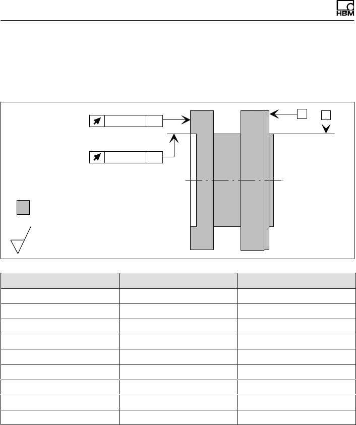
Ergänzende technische Informationen
80 A3452-10.0 T40B
14 Ergänzende technische Informationen
Plan‐ und Rundlauftoleranzen
Innenzentrierung
A
Planlauf AB B
Härte 46 ... 54 HRC
Oberflächengüte der Plan‐ und
Rundlaufflächen (A, B und AB)
0,8
Rundlauf AB
Messbereich (NVm) Planlauftoleranz (mm) Rundlauftoleranz (mm)
50 0,01 0,01
100 0,01 0,01
200 0,01 0,01
500 0,01 0,01
1 k 0,01 0,01
2 k 0,02 0,02
3 k 0,02 0,02
5 k 0,02 0,02
10 k 0,02 0,02
Um die Eigenschaften des Drehmoment‐Messflanschs
im eingebauten Zustand zu erhalten, empfehlen wir die
angegebenen Form‐ und Lagetoleranzen, Oberflächen
güte und Härte auch für die kundenseitigen Anschlüsse
zu wählen.
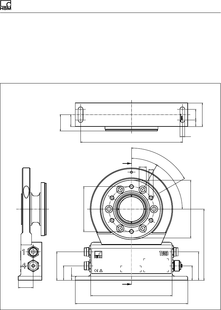
Dimensions | Abmessungen
T40B A3452-10.0 81
15 Dimensions | Abmessungen
15.1 T40B without rotational speed measurement |
T40B ohne Drehzahlmessung
15.1.1 T40B 50Nm - 100Nm, Option 7, Code S
Dimensions in mm (1 mm = 0.03937 inches) | Abmessungen in mm
A
A
(22)
(30,5)
∅84
190
9
12 20
44
28
210
152
27
53
27
53
133
∅108
30°
6x60° = 360°
60°
∅14M8
7,5
60°
Montagemaß
Mounting
dimensions
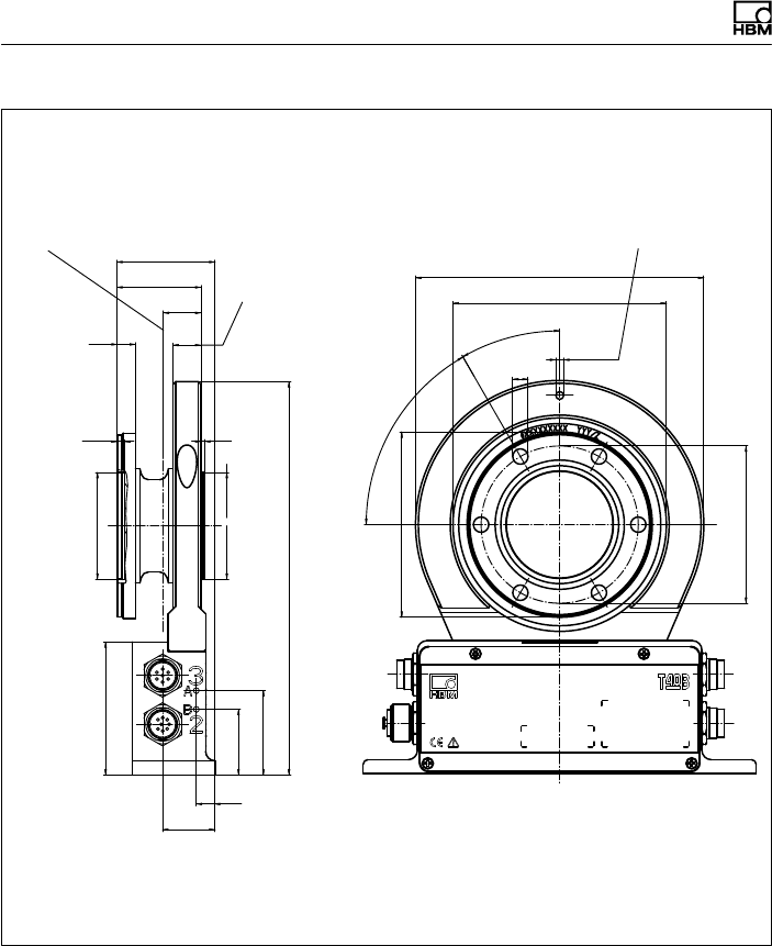
Dimensions | Abmessungen
82 A3452-10.0 T40B
Dimensions in mm (1 mm = 0.03937 inches) | Abmessungen in mm
C12
20
∅84
71
28
35
45
10
210
2
56,990
56,977
∅57 g5 ()
4,2
57,019
57,000
∅57 H6 ()
10
45
15
52,5
∅99
30°
∅8,2
∅4,2
∅114
∅154
6x60° =
360°
60°
Schwerpunkt Zur Axialsicherung
Entspricht Statorring,
wie Messkörperflansch
(Einschraubtiefe)
Ausbruch Innenzentrierung
im Schnitt A-A
Corr. to stator ring and
meas. body flange
(thread reach) For axial locking
Center of gravity
Cutaway of internal centering
in section A-A
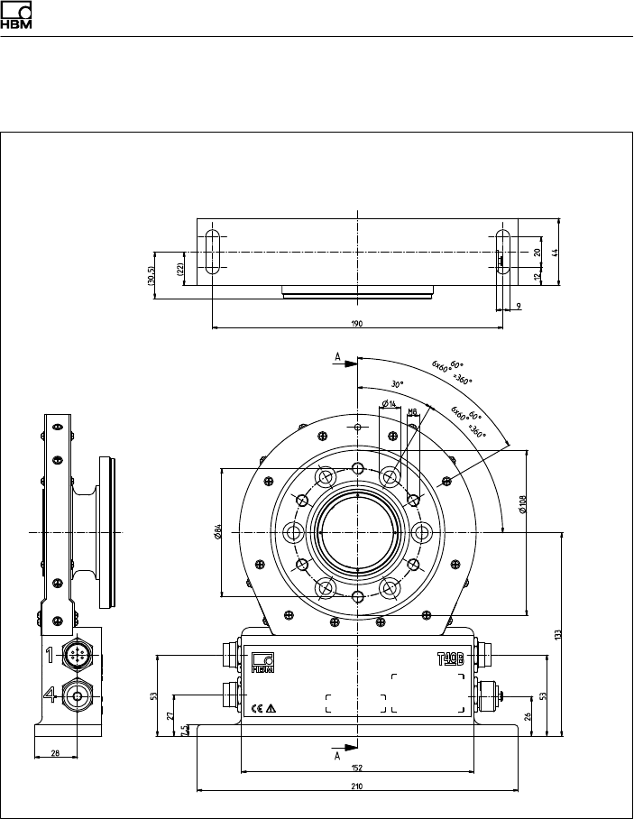
Dimensions | Abmessungen
T40B A3452-10.0 83
15.1.2 T40B 50 Nm, 100 Nm, Option 7, Code U
Dimensions in mm (1 mm = 0.03937 inches) | Abmessungen in mm
Screw head height (Shielding plates) = 2.5 mm |
Schraubenkopfhöhe (Abschirmungsplatten) = 2,5 mm
Montagemaß
Mounting
dimensions
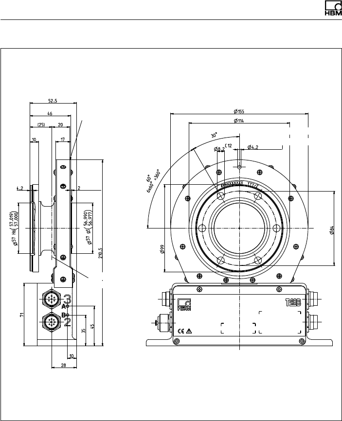
Dimensions | Abmessungen
84 A3452-10.0 T40B
Corr. to stator ring and
meas. body flange see
Option 7, Code S
Dimensions in mm (1 mm = 0.03937 inches) | Abmessungen in mm
Screw head height (Shielding plates) = 2.5 mm |
Schraubenkopfhöhe (Abschirmungsplatten) = 2,5 mm
Ausbruch Innenzentrierung
im Schnitt A-A
Cutaway of internal centering
in section A-A
Entspricht Statorring,
wie Messkörperflansch
siehe Option 7, Code S Zur Axialsicherung
For axial locking
Schwerpunkt
Center of gravity
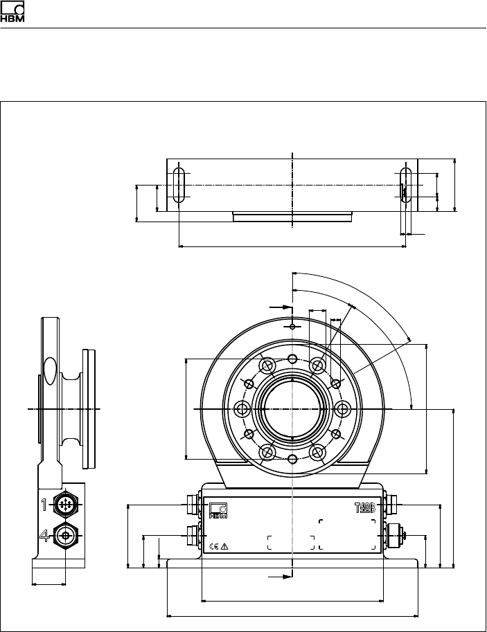
Dimensions | Abmessungen
T40B A3452-10.0 85
15.1.3 T40B 200Nm, Option 7, Code S
Dimensions in mm (1 mm = 0.03937 inches) | Abmessungen in mm
A
A
(22)
Montagemaß
(30,5)
∅84
190
9
20
44
28
210
152
27
53
27
53
133
∅108
30°
6x60° = 360°
60°
∅14M8
7,5
12
60°
Mounting
dimensions
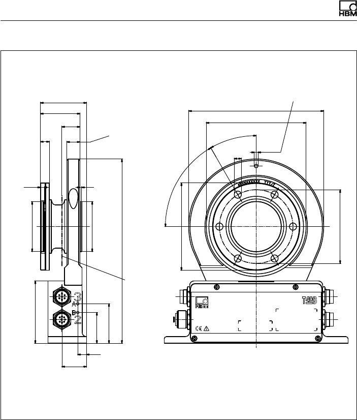
Dimensions | Abmessungen
86 A3452-10.0 T40B
C12
20,6
∅84
71
28
35
45
10
210
2
56,990
56,977
∅57 g5
4,2
57,019
57,000
∅57 H6
10
45
15
52,5
∅99,6
30°
6x60° =
360°
∅8,2 ∅4,2
∅114
∅154
Schwerpunkt
Zur Axialsicherung
Entspricht Statorring,
wie Messkörperflansch
(Einschraubtiefe)
60°
()
()
Ausbruch Innenzentrierung
im Schnitt A-A
Corr. to stator ring and
meas. body flange
(thread reach)
For axial locking
Center of gravity
Cutaway of internal centering
in section A-A
Dimensions in mm (1 mm = 0.03937 inches) | Abmessungen in mm
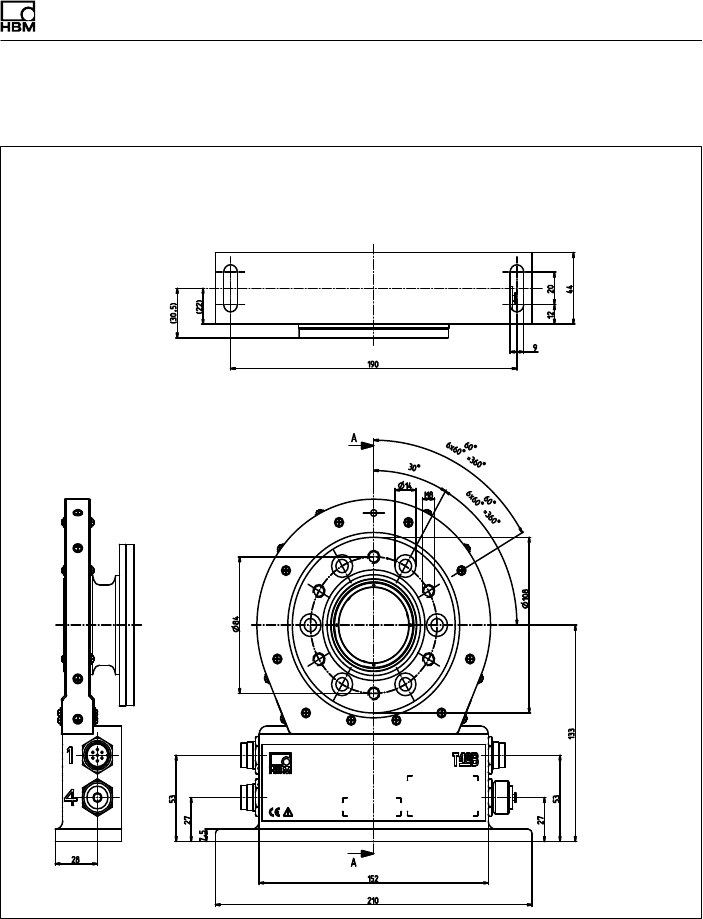
Dimensions | Abmessungen
T40B A3452-10.0 87
15.1.4 T40B 200 Nm, Option 7, Code U
Dimensions in mm (1 mm = 0.03937 inches) | Abmessungen in mm
Screw head height (Shielding plates) = 2.5 mm |
Schraubenkopfhöhe (Abschirmungsplatten) = 2,5 mm
Montagemaß
Mounting
dimensions
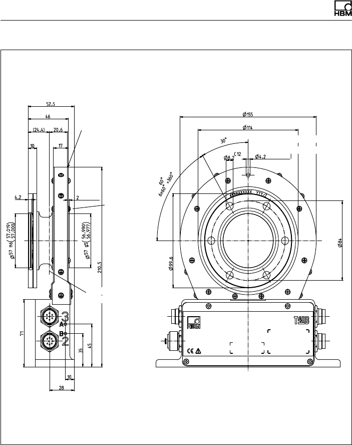
Dimensions | Abmessungen
88 A3452-10.0 T40B
Dimensions in mm (1 mm = 0.03937 inches) | Abmessungen in mm
Screw head height (Shielding plates) = 2.5 mm |
Schraubenkopfhöhe (Abschirmungsplatten) = 2,5 mm
Ausbruch Innenzentrierung
im Schnitt A-A
Cutaway of internal centering
in section A-A
Corr. to stator ring and
meas. body flange see
Option 7, Code S
Entspricht Statorring,
wie Messkörperflansch
siehe Option 7, Code S Zur Axialsicherung
For axial locking
Schwerpunkt
Center of gravity
External
centering
Außen
zentrierung
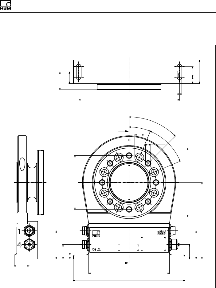
Dimensions | Abmessungen
T40B A3452-10.0 89
15.1.5 T40B 500Nm - 1kNm, Option 7, Code S
A
A
(22)
Montagemaß
(33,5)
∅101,5
190
9
20
44
28
210
152
27
53
27
53
144
∅130
22,5°
45°
8x45° = 360°
45°
∅17
M10
7,5
12
Mounting
dimensions
Dimensions in mm (1 mm = 0.03937 inches) | Abmessungen in mm
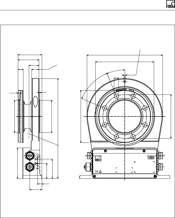
Dimensions | Abmessungen
90 A3452-10.0 T40B
C12
23,3
∅101,5
71
28
35
45
10
232
2
74,990
74,977
∅75 g5
4,2
75,019
75,000
∅75 H6 )
12
49
17
55,5
∅121
22,5°
8x45°=
360°45°
∅10,5 ∅4,2
∅176
∅136
()
Dimensions in mm (1 mm = 0.03937 inches) | Abmessungen in mm
Schwerpunkt
Zur Axialsicherung
Entspricht Statorring, wie Mess
körperflansch
(Einschraubtiefe)
Ausbruch Innenzentrierung
im Schnitt A-A
Corr. to stator ring and meas.
body flange (thread reach) For axial locking
Center of
gravity
Cutaway of internal centering
in section A-A
(
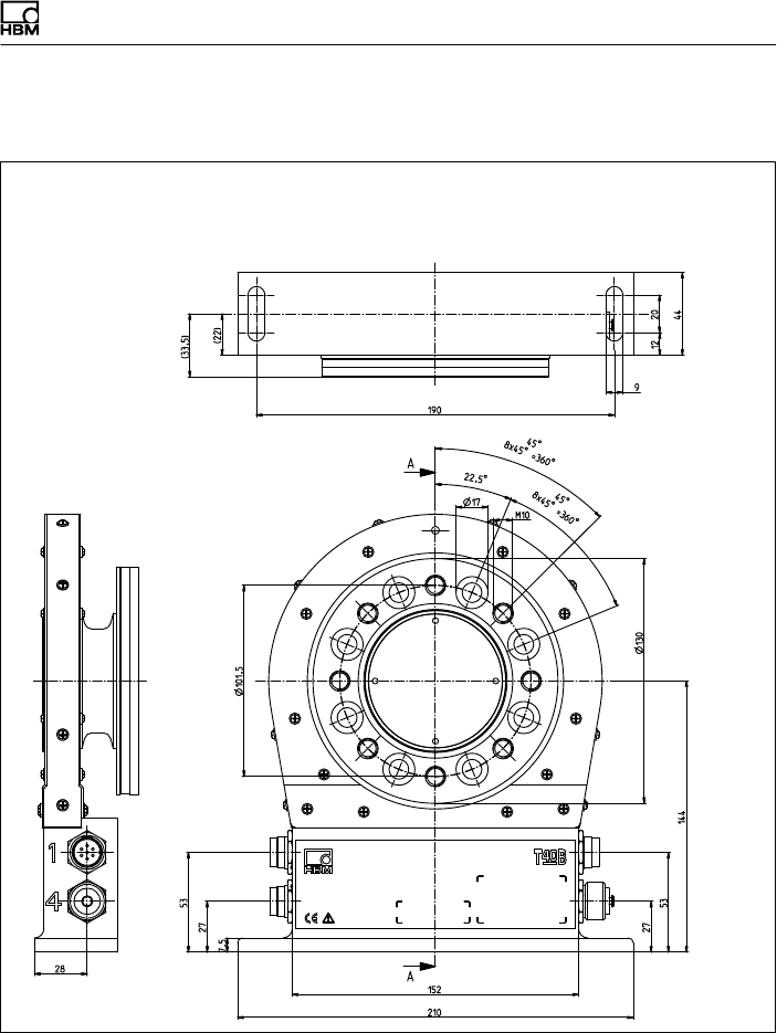
Dimensions | Abmessungen
T40B A3452-10.0 91
15.1.6 T40B 500 Nm - 1 kNm, Option 7, Code U
Dimensions in mm (1 mm = 0.03937 inches) | Abmessungen in mm
Screw head height (Shielding plates) = 2.5 mm |
Schraubenkopfhöhe (Abschirmungsplatten) = 2,5 mm
Montagemaß
Mounting
dimensions
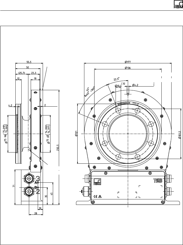
Dimensions | Abmessungen
92 A3452-10.0 T40B
Dimensions in mm (1 mm = 0.03937 inches) | Abmessungen in mm
Screw head height (Shielding plates) = 2.5 mm |
Schraubenkopfhöhe (Abschirmungsplatten) = 2,5 mm
Ausbruch Innenzentrierung
im Schnitt A-A
Cutaway of internal centering
in section A-A
Corr. to stator ring and meas.
body flange see Option 7, Code S
Entspricht Stator
ring, wie Mess
körperflansch
siehe Option 7,
Code S Zur Axialsicherung
For axial locking
Schwerpunkt
Center of gravity
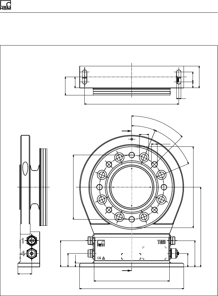
Dimensions | Abmessungen
T40B A3452-10.0 93
15.1.7 T40B 2kNm - 3kNm, Option 7, Code S
A
A
(22)
Montagemaß
(37)
∅130
190
9
20
44
28
210
152
27
53
27
53
161
∅164
22,5°
45°
8x45° = 360°
45°
∅19
M12
7,5
Mounting
dimensions
Dimensions in mm (1 mm = 0.03937 inches) | Abmessungen in mm
12
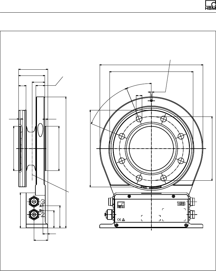
Dimensions | Abmessungen
94 A3452-10.0 T40B
C12
∅130
25,7
71
28
35
45
10
266
2,5
89,988
89,973
∅90 g5
4,2
90,022
90,000
∅90 H6
15
53
18
59
∅156
22,5°
8x45° = 360°45°
∅12 ∅4,2
∅210
∅170
()
()
Dimensions in mm (1 mm = 0.03937 inches) | Abmessungen in mm
Schwerpunkt
Zur Axialsicherung
Entspricht Statorring, wie
Messkörperflansch
(Einschraubtiefe)
Ausbruch Innenzentrierung
im Schnitt A-A
Corr. to stator ring and meas. body
flange (thread reach) For axial locking
Center of
gravity
Cutaway of internal centering
in section A-A
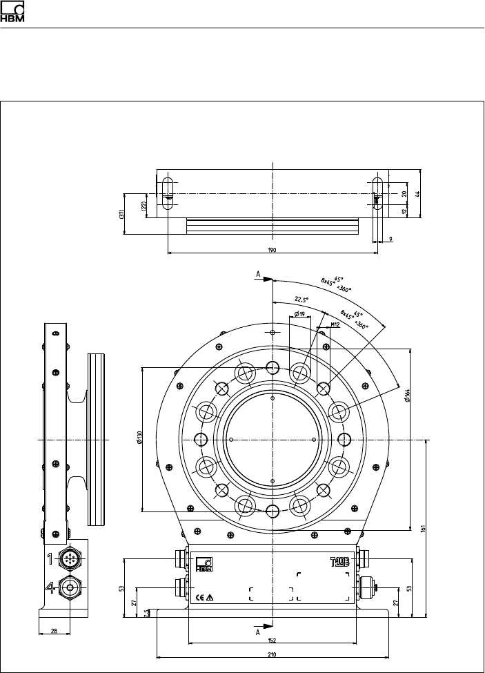
Dimensions | Abmessungen
T40B A3452-10.0 95
15.1.8 T40B 2 kNm - 3 kNm, Option 7, Code U
Dimensions in mm (1 mm = 0.03937 inches) | Abmessungen in mm
Screw head height (Shielding plates) = 2.5 mm |
Schraubenkopfhöhe (Abschirmungsplatten) = 2,5 mm
Montagemaß
Mounting
dimensions
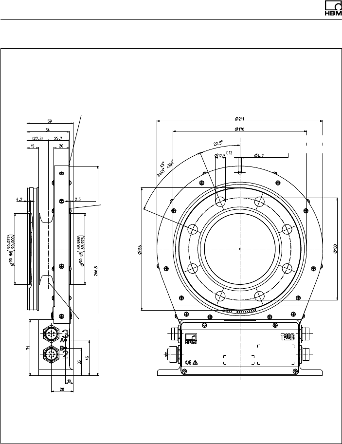
Dimensions | Abmessungen
96 A3452-10.0 T40B
Dimensions in mm (1 mm = 0.03937 inches) | Abmessungen in mm
Screw head height (Shielding plates) = 2.5 mm |
Schraubenkopfhöhe (Abschirmungsplatten) = 2,5 mm
Ausbruch Innenzentrierung
im Schnitt A-A
Cutaway of internal centering
in section A-A
Corr. to stator ring and meas. body
flange see Option 7, Code S
Entspricht Stator
ring, wie Mess
körperflansch
siehe Option 7,
Code S Zur Axialsicherung
For axial locking
Schwerpunkt
Center of gravity
External
centering
Außen
zentrierung
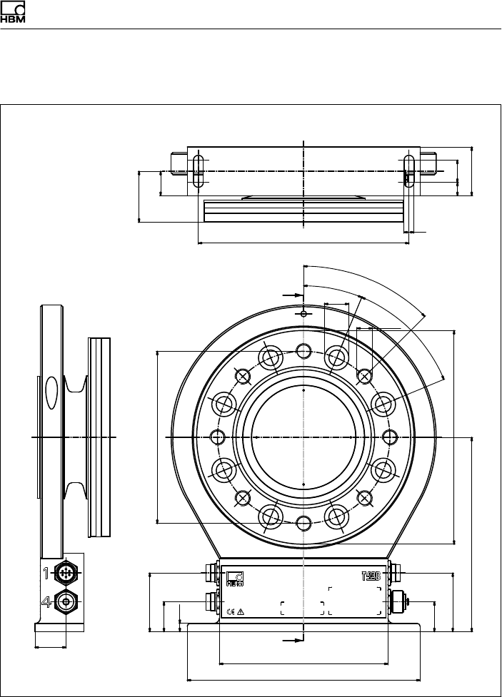
Dimensions | Abmessungen
T40B A3452-10.0 97
15.1.9 T40B 5kNm, Option 7, Code S
A
A
(22)
Montagemaß
(46)
∅155,5
190 9
12 20
44
28
210
152
27
53
27
53
175,5
∅193
22,5°
45°
8x45° = 360°
45°
∅22
M14
7,5
Mounting
dimensions
Dimensions in mm (1 mm = 0.03937 inches) | Abmessungen in mm
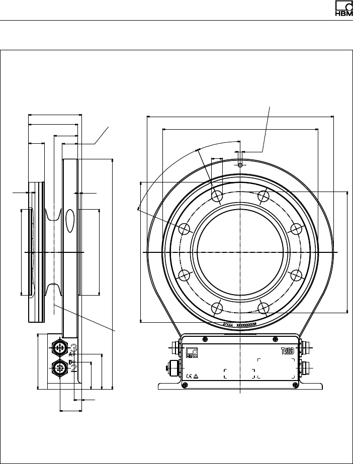
Dimensions | Abmessungen
98 A3452-10.0 T40B
C12
∅155,5
30,5
71
28
35
45
10
295
2,8
109,988
109,973
∅110 g5
4,2
110,022
110,000
∅110 H6
20
63
20
68
∅180
22,5°
8x45° =
360°
45°
∅14,2 ∅5,2
∅239
∅199
()
()
Dimensions in mm (1 mm = 0.03937 inches) | Abmessungen in mm
Schwerpunkt
Zur Axialsicherung
Entspricht Statorring, wie
Messkörperflansch
(Einschraubtiefe)
Ausbruch Innenzentrierung
im Schnitt A-A
Corr. to stator ring and meas.
body flange (thread reach) For axial locking
Center of
gravity
Cutaway of internal centering
in section A-A
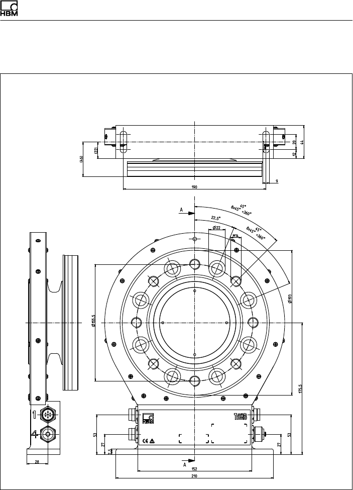
Dimensions | Abmessungen
T40B A3452-10.0 99
15.1.10T40B 5 kNm, Option 7, Code U
Dimensions in mm (1 mm = 0.03937 inches) | Abmessungen in mm
Screw head height (Shielding plates) = 2.5 mm |
Schraubenkopfhöhe (Abschirmungsplatten) = 2,5 mm
Montagemaß
Mounting
dimensions
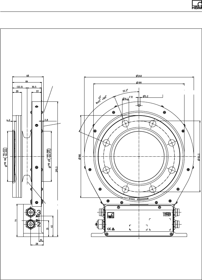
Dimensions | Abmessungen
100 A3452-10.0 T40B
Dimensions in mm (1 mm = 0.03937 inches) | Abmessungen in mm
Screw head height (Shielding plates) = 2.5 mm |
Schraubenkopfhöhe (Abschirmungsplatten) = 2,5 mm
Ausbruch Innenzentrierung
im Schnitt A-A
Cutaway of internal centering
in section A-A
Corr. to stator ring and meas. body flange see
Option 7, Code S
Entspricht Statorring, wie Messkörperflansch
siehe Option 7,
Code S
Zur Axialsicherung
For axial locking
Schwerpunkt
Center of gravity
External
centering
Außen
zentrierung
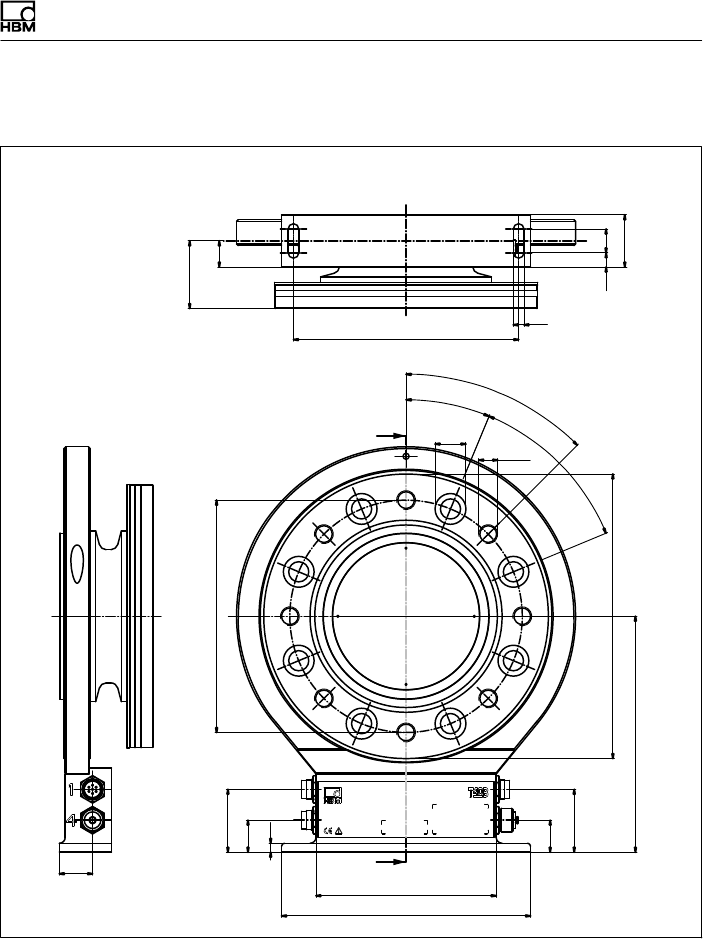
Dimensions | Abmessungen
T40B A3452-10.0 101
15.1.11T40B 10kNm, Option 7, Code S
A
A
(22)
Montagemaß
(57)
∅196
190 9
12 20
44
28
210
152
27
53
27
53
199
∅240
22,5°
45°
8x45° = 360°
45°
∅26 M16
7,5
Mounting
dimensions
Dimensions in mm (1 mm = 0.03937 inches) | Abmessungen in mm
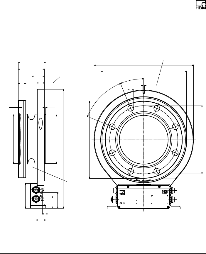
Dimensions | Abmessungen
102 A3452-10.0 T40B
C12
∅196
36
71
28
35
45
10
342
3,5
139,986
139,968
∅140 g5
4,2
140,025
140,000
∅140 H6
22
75
22
79
∅222
22,5°
8x45° =
360°45°
∅17 ∅5,2
∅286
∅246
()
()
Dimensions in mm (1 mm = 0.03937 inches) | Abmessungen in mm
Schwerpunkt
Zur Axialsicherung
Entspricht Statorring, wie
Messkörperflansch
(Einschraubtiefe)
Ausbruch Innenzentrierung
im Schnitt A-A
Corr. to stator ring and meas.
body flange (thread reach) For axial locking
Center of gravity
Cutaway of internal centering
in section A-A
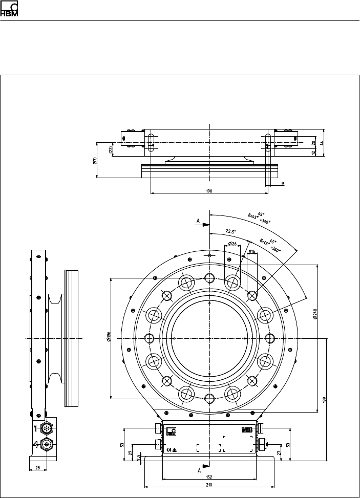
Dimensions | Abmessungen
T40B A3452-10.0 103
15.1.12T40B 10 kNm, Option 7, Code U
Dimensions in mm (1 mm = 0.03937 inches) | Abmessungen in mm
Screw head height (Shielding plates) = 2.5 mm |
Schraubenkopfhöhe (Abschirmungsplatten) = 2,5 mm
Montagemaß
Mounting
dimensions
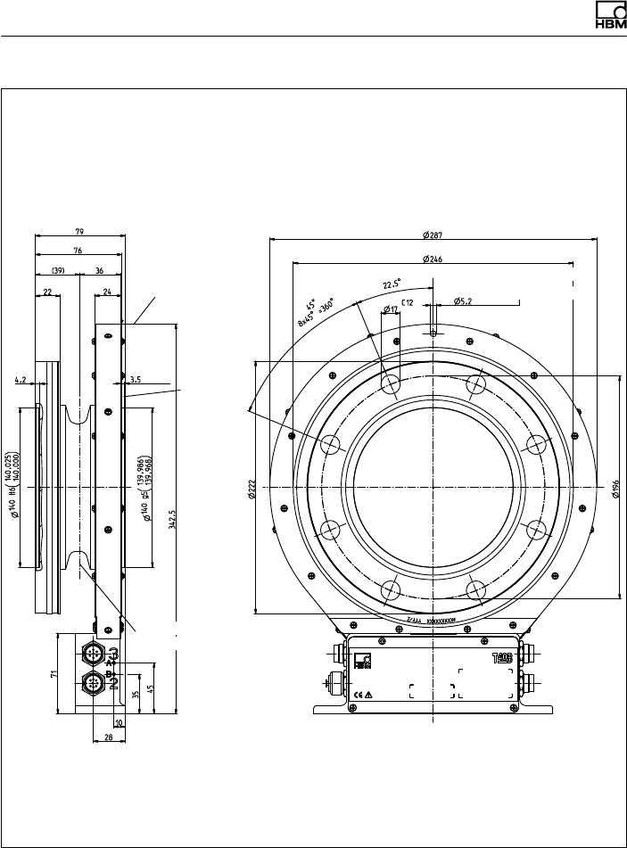
Dimensions | Abmessungen
104 A3452-10.0 T40B
Dimensions in mm (1 mm = 0.03937 inches) | Abmessungen in mm
Screw head height (Shielding plates) = 2.5 mm |
Schraubenkopfhöhe (Abschirmungsplatten) = 2,5 mm
Ausbruch Innenzentrierung
im Schnitt A-A
Cutaway of internal centering
in section A-A
Corr. to stator ring and meas. body flange see
Option 7, Code S
Entspricht Stator
ring, wie Mess
körperflansch
siehe Option 7,
Code S Zur Axialsicherung
For axial locking
Schwerpunkt
Center of gravity
External
centering
Außen
zentrierung
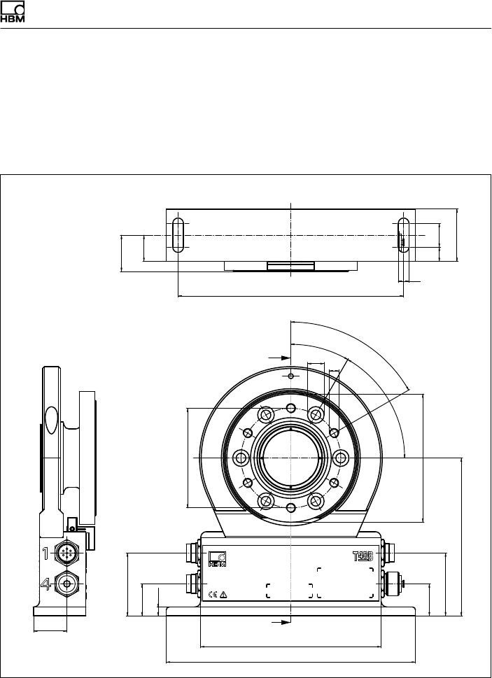
Dimensions | Abmessungen
T40B A3452-10.0 105
15.2 T40B with rot. speed measurement
and reference signal | mit Drehzahl
messung und Referenzimpuls
15.2.1 T40B 50Nm - 100Nm, Option 7, Code S
Dimensions in mm (1 mm = 0.03937 inches) | Abmessungen in mm
A
A
(22)
(30,5)
∅84
12 20
44
9
190
28
210
152
27
53
27
53
133
∅108
30°
6x60° = 360°
60°
∅14M8
7,5
60°
Montagemaß
Mounting
dimensions
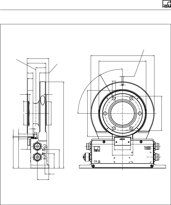
Dimensions | Abmessungen
106 A3452-10.0 T40B
Dimensions in mm (1 mm = 0.03937 inches) | Abmessungen in mm
C12
∅84
24
∅112
∅4,2
30°
∅8,2
10
28
35
45
71
210
2
4,2
56,990
56,977
∅57 g5()
57,019
57,000
∅57 H6()
7,5 40
1,6
(75,4)
15
45
52,5
13
14
∅154
∅114
28
50
12
Schwerpunkt
Entspricht Statorring, wie
Messkörperflansch
(Einschraubtiefe)
Zur Axialsicherung
6x60° =
360°
60°
Ausbruch Innenzentrierung
im Schnitt A-A
Corr. to stator ring and meas.
body flange (thread reach) For axial locking
Center of gravity
Cutaway of internal centering
in section A-A
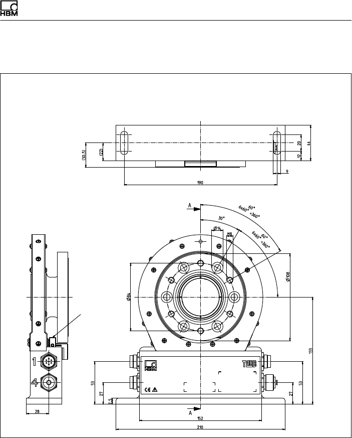
Dimensions | Abmessungen
T40B A3452-10.0 107
15.2.2 T40B 50 kNm - 100 Nm, Option 7, Code U
Dimensions in mm (1 mm = 0.03937 inches) | Abmessungen in mm
Screw head height (Shielding plates) = 2.5 mm |
Schraubenkopfhöhe (Abschirmungsplatten) = 2,5 mm
Montagemaß
Mounting
dimensions
Only
Option 6,
Code A
Nur
Option 6,
Code A
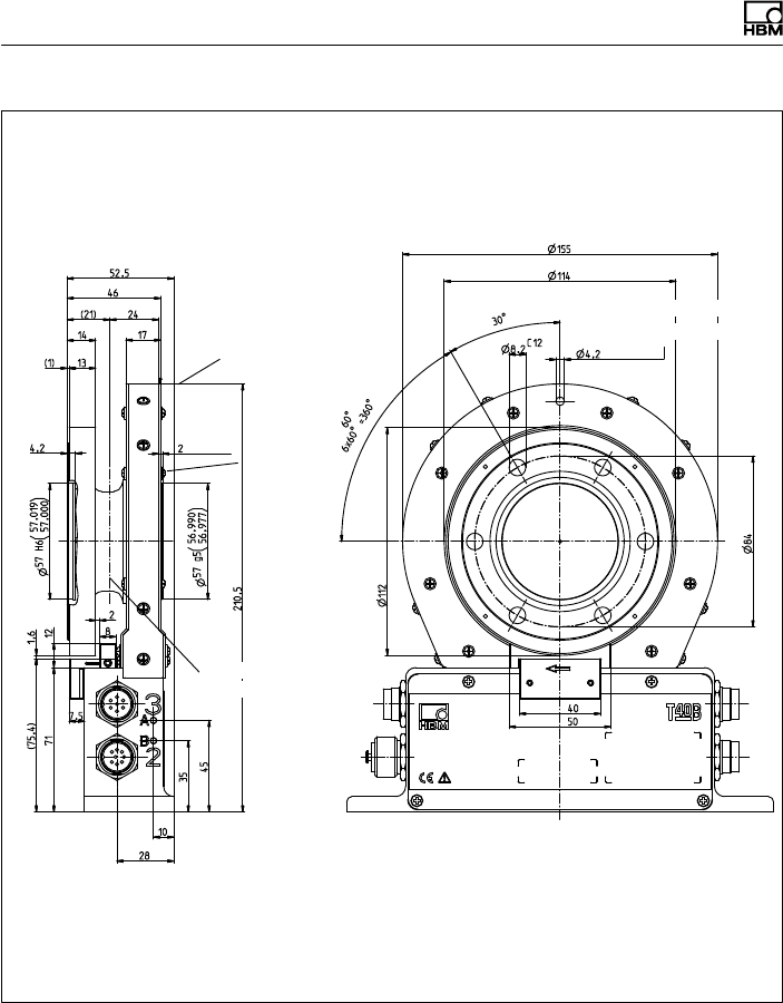
Dimensions | Abmessungen
108 A3452-10.0 T40B
Dimensions in mm (1 mm = 0.03937 inches) | Abmessungen in mm
Screw head height (Shielding plates) = 2.5 mm |
Schraubenkopfhöhe (Abschirmungsplatten) = 2,5 mm
Ausbruch Innenzentrierung
im Schnitt A-A
Cutaway of internal centering
in section A-A
Corr. to stator ring and
meas. body flange see
Option 7, Code S
Entspricht Statorring,
wie Messkörperflansch
siehe Option 7, Code S Zur Axialsicherung
For axial locking
Schwerpunkt
Center of gravity
External
centering
Außen
zentrierung
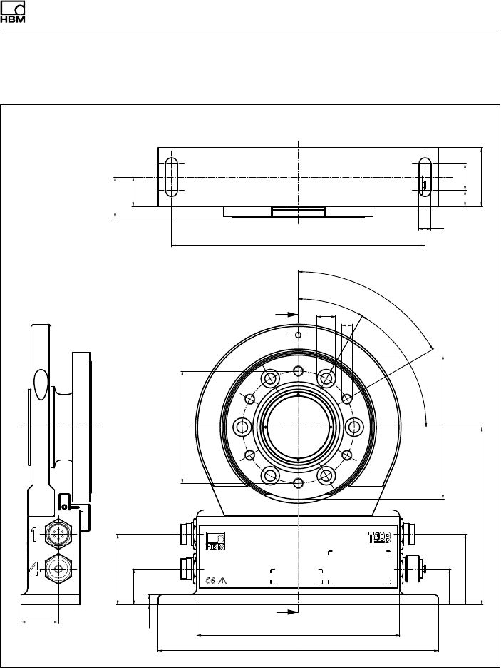
Dimensions | Abmessungen
T40B A3452-10.0 109
15.2.3 T40B 200Nm, Option 7, Code S
A
A
(22)
(30,5)
∅84
12 20
44
9
190
28
210
152
27
53
27
53
133
∅108
30°60°
6 x 60° = 360°
60°
∅14M8
7,5
Mounting
dimensions
Dimensions in mm (1 mm = 0.03937 inches) | Abmessungen in mm
Montagemaß
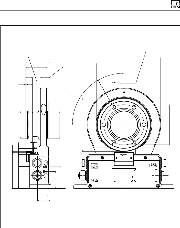
Dimensions | Abmessungen
110 A3452-10.0 T40B
C12
∅84
21,9
∅112
∅4,2
30°
6 x 60° = 360°
60°
∅8,2
10
28
35
45
71
210
2
4,2
56,990
56,977
∅57 g5()
57,019
57,000
∅57 H6 ()
7,5 40
1,6
(75,4)
15
45
52,5
13
14
(1)
∅154
∅114
2
8
50
12
Dimensions in mm (1 mm = 0.03937 inches) | Abmessungen in mm
Schwerpunkt Zur Axialsicherung
Entspricht Statorring, wie
Messkörperflansch
(Einschraubtiefe)
Ausbruch Innenzentrierung
im Schnitt A-A
Corr. to stator ring and meas.
body flange (thread reach) For axial locking
Center of gravity
Cutaway of internal centering
in section A-A
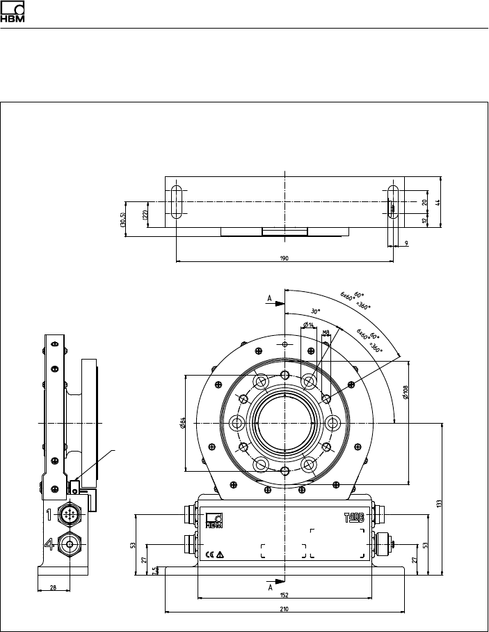
Dimensions | Abmessungen
T40B A3452-10.0 111
15.2.4 T40B 200 Nm, Option 7, Code U
Dimensions in mm (1 mm = 0.03937 inches) | Abmessungen in mm
Screw head height (Shielding plates) = 2.5 mm |
Schraubenkopfhöhe (Abschirmungsplatten) = 2,5 mm
Montagemaß
Mounting
dimensions
Only
Option 6,
Code A
Nur
Option 6,
Code A
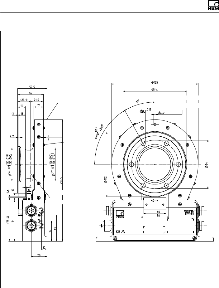
Dimensions | Abmessungen
112 A3452-10.0 T40B
Dimensions in mm (1 mm = 0.03937 inches) | Abmessungen in mm
Screw head height (Shielding plates) = 2.5 mm |
Schraubenkopfhöhe (Abschirmungsplatten) = 2,5 mm
Ausbruch Innenzentrierung
im Schnitt A-A
Cutaway of internal centering
in section A-A
Corr. to stator ring and
meas. body flange see
Option 7, Code S
Entspricht Statorring,
wie Messkörperflansch
siehe Option 7, Code S
Zur Axialsicherung
For axial locking
Schwerpunkt
Center of gravity
External
centering
Außen
zentrierung
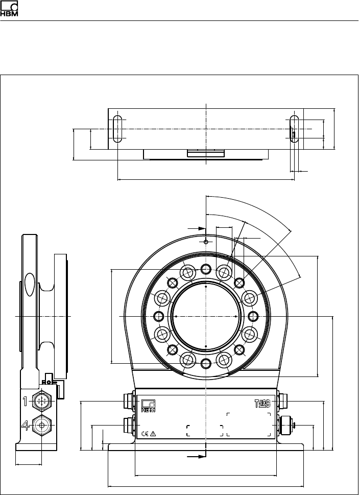
Dimensions | Abmessungen
T40B A3452-10.0 113
15.2.5 T40B 500Nm - 1kNm, Option 7, Code S
(22)
(33,5)
∅101,5
190 9
12 20
44
28
27
53
210
152
27
53
144
∅130
22,5°
∅17
M10
8 x 45° = 360°
45°
7,5
A
A
45°
Mounting
dimensions
Dimensions in mm (1 mm = 0.03937 inches) | Abmessungen in mm
Montagemaß
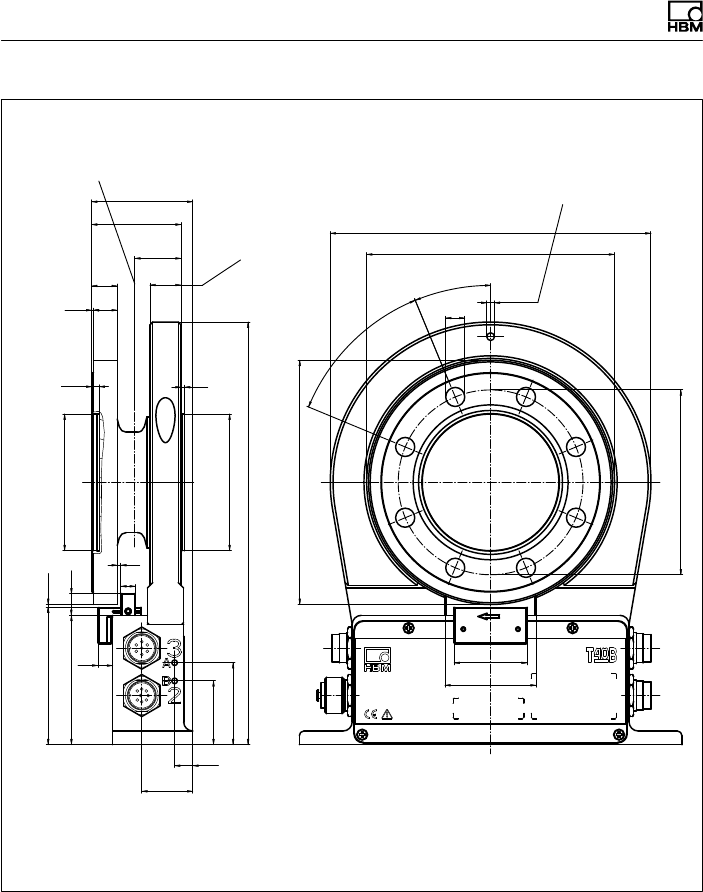
Dimensions | Abmessungen
114 A3452-10.0 T40B
C12
∅101,5
25,3
∅134
40
∅4,2
∅10,5
22,5°
8 x 45° =
360°
45°
10
28
35
45
71
(75,4) 1,6
8
232
2
4,2
74,990
74,977
∅75 g5 ()
75,019
75,000
∅75 H6 ()
(1) 13
14 17
49
55,5
∅176
∅136
50
12
8
2
Dimensions in mm (1 mm = 0.03937 inches) | Abmessungen in mm
Schwerpunkt
Zur Axialsicherung
Entspricht Statorring, wie
Messkörperflansch
(Einschraubtiefe)
Ausbruch Innenzentrierung
im Schnitt A-A
Corr. to stator ring and meas.
body flange (thread reach) For axial locking
Center of gravity
Cutaway of internal centering
in section A-A
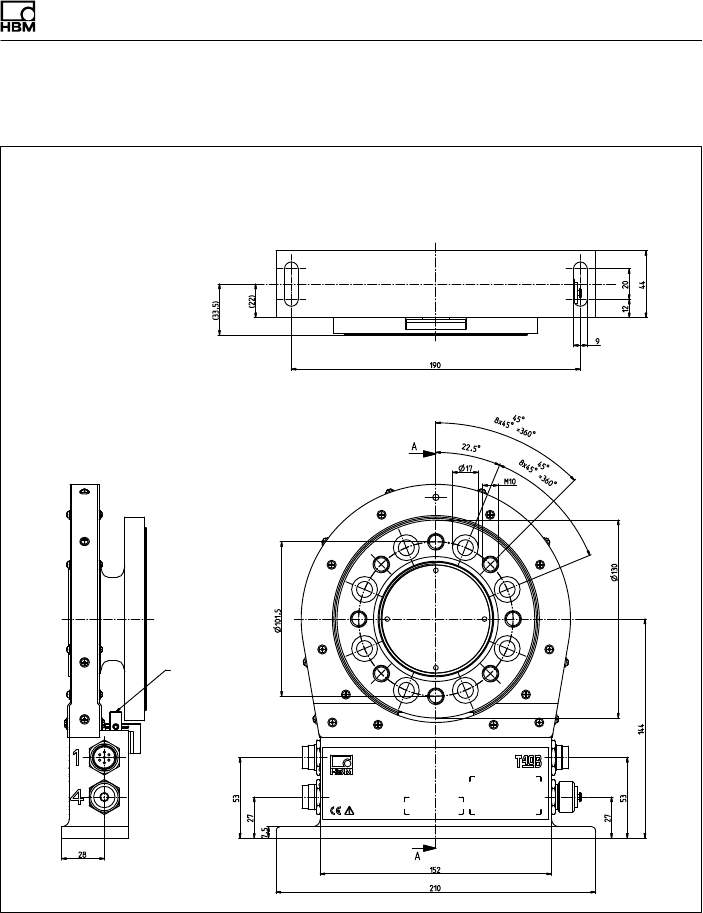
Dimensions | Abmessungen
T40B A3452-10.0 115
15.2.6 T40B 500 Nm - 1 kNm, Option 7, Code U
Dimensions in mm (1 mm = 0.03937 inches) | Abmessungen in mm
Screw head height (Shielding plates) = 2.5 mm |
Schraubenkopfhöhe (Abschirmungsplatten) = 2,5 mm
Montagemaß
Mounting
dimensions
Only
Option 6,
Code A
Nur
Option 6,
Code A
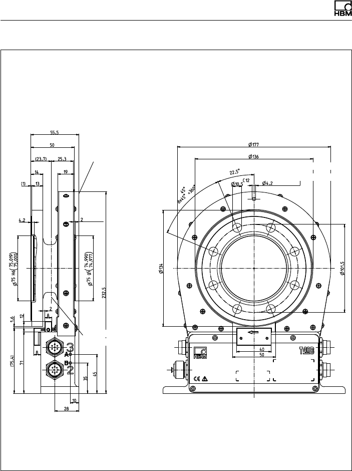
Dimensions | Abmessungen
116 A3452-10.0 T40B
Dimensions in mm (1 mm = 0.03937 inches) | Abmessungen in mm
Screw head height (Shielding plates) = 2.5 mm |
Schraubenkopfhöhe (Abschirmungsplatten) = 2,5 mm
Ausbruch Innenzentrierung
im Schnitt A-A
Cutaway of internal centering
in section A-A
Corr. to stator ring and
meas. body flange see
Option 7, Code S
Entspricht Statorring,
wie Messkörperflansch
siehe Option 7, Code S
Zur Axialsicherung
For axial locking
Schwerpunkt
Center of gravity
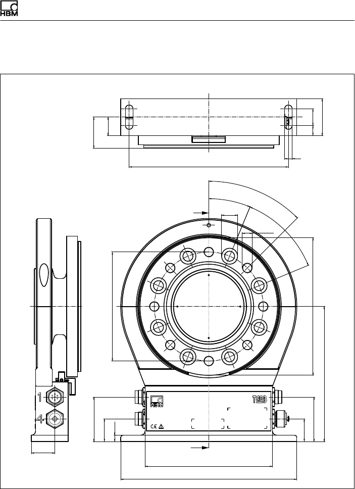
Dimensions | Abmessungen
T40B A3452-10.0 117
15.2.7 T40B 2kNm - 3kNm, Option 7, Code S
(22)
(37)
190 9
12 20
44
Montagemaß
28
∅130
210
152
27
53
27
53
161
∅164
∅19
M12
22,5°
45°
8 x 45° = 360°
45°
7,5
A
A
Mounting
dimensions
Dimensions in mm (1 mm = 0.03937 inches) | Abmessungen in mm
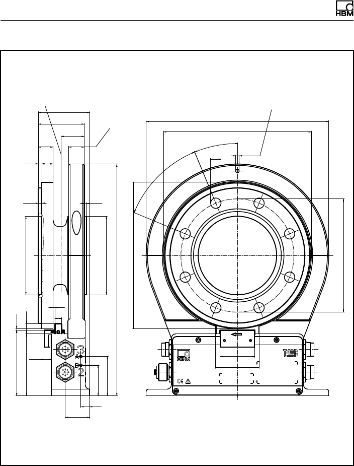
Dimensions | Abmessungen
118 A3452-10.0 T40B
26,8
10
28
35
45
71
8,5
(75,4) 1,6
266
2,5
89,988
89,973
∅90 g5
4,2
( )
(4) 13
17 18
53
59
8
2
12 90,022
90,000
∅90 H6 ()
8 x 45° =
360°
45°C12
∅130
∅168
∅4,2
22,5°
∅12
40
∅210
∅170
50
Dimensions in mm (1 mm = 0.03937 inches) | Abmessungen in mm
Schwerpunkt Zur Axialsicherung
Entspricht Statorring, wie
Messkörperflansch
(Einschraubtiefe)
Ausbruch Innenzentrierung im
Schnitt A-A
Corr. to stator ring and meas.
body flange (thread reach)
For axial locking
Center of gravity
Cutaway of internal centering
in section A-A
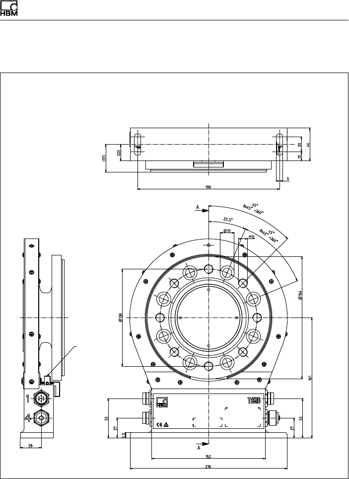
Dimensions | Abmessungen
T40B A3452-10.0 119
15.2.8 T40B 2 kNm - 3 kNm, Option 7, Code U
Dimensions in mm (1 mm = 0.03937 inches) | Abmessungen in mm
Screw head height (Shielding plates) = 2.5 mm |
Schraubenkopfhöhe (Abschirmungsplatten) = 2,5 mm
Montagemaß
Mounting
dimensions
Only
Option 6,
Code A
Nur
Option 6,
Code A
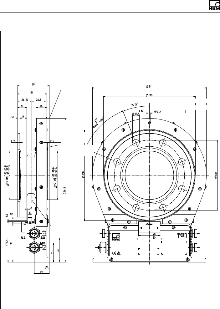
Dimensions | Abmessungen
120 A3452-10.0 T40B
Dimensions in mm (1 mm = 0.03937 inches) | Abmessungen in mm
Screw head height (Shielding plates) = 2.5 mm |
Schraubenkopfhöhe (Abschirmungsplatten) = 2,5 mm
Ausbruch Innenzentrierung
im Schnitt A-A
Cutaway of internal centering
in section A-A
Corr. to stator ring and meas. body flange
see Option 7, Code S
Entspricht Statorring, wie Messkörperflansch
siehe Option 7, Code S
Zur Axialsicherung
For axial locking
Schwerpunkt
Center of gravity
External
centering
Außen
zentrierung
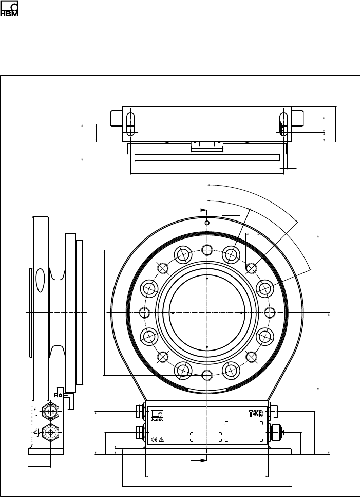
Dimensions | Abmessungen
T40B A3452-10.0 121
15.2.9 T40B 5kNm, Option 7, Code S
28
∅155,5
210
152
27
53
27
53
175,5
∅193
∅22
M14
22,5°
45°
8 x 45° = 360°
45°
7,5
A
A
(22)
(46)
190 9
12 20
44
Montagemaß
Mounting
dimensions
Dimensions in mm (1 mm = 0.03937 inches) | Abmessungen in mm
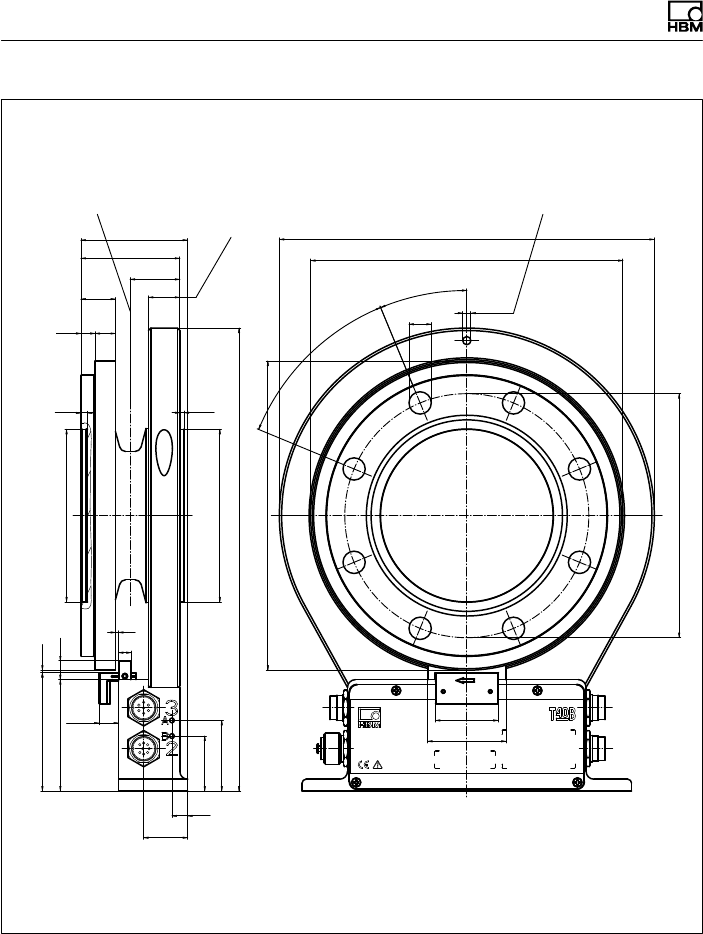
Dimensions | Abmessungen
122 A3452-10.0 T40B
31,6
10
28
35
45
71
12,5
(75,4) 1,6
295
4,2 2,8
109,988
109,973
∅110 g5 ()
(9) 13
22 20
63
68
8
2
12 110,022
110,000
∅110 H6 ()
C12
∅155,5
∅5,2
∅14,2
22,5°
8 x 45° =
360°
45°
40
∅197
∅239
∅199
50
Dimensions in mm (1 mm = 0.03937 inches) | Abmessungen in mm
Schwerpunkt Zur Axialsicherung
Entspricht Statorring, wie Mess
körperflansch (Einschraubtiefe)
Ausbruch Innenzentrierung im
Schnitt A-A
Corr. to stator ring and meas.
body flange (thread reach) For axial locking
Center of gravity
Cutaway of internal centering in
section A-A
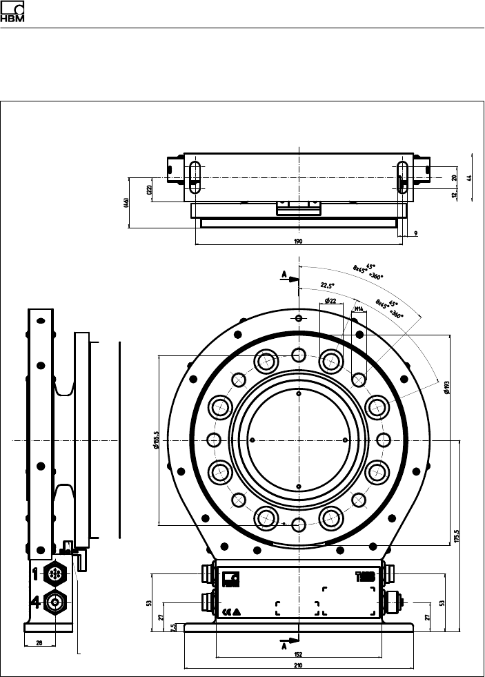
Dimensions | Abmessungen
T40B A3452-10.0 123
15.2.10T40B 5 kNm, Option 7, Code U
Dimensions in mm (1 mm = 0.03937 inches) | Abmessungen in mm
Screw head height (Shielding plates) = 2.5 mm |
Schraubenkopfhöhe (Abschirmungsplatten) = 2,5 mm
Montagemaß
Mounting
dimensions
Only
Option 6,
Code A
Nur
Option 6,
Code A
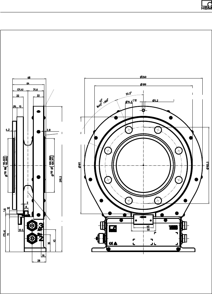
Dimensions | Abmessungen
124 A3452-10.0 T40B
Dimensions in mm (1 mm = 0.03937 inches) | Abmessungen in mm
Screw head height (Shielding plates) = 2.5 mm |
Schraubenkopfhöhe (Abschirmungsplatten) = 2,5 mm
Ausbruch Innenzentrierung
im Schnitt A-A
Cutaway of internal centering
in section A-A
Corr. to stator ring and meas. body flange
see Option 7, Code S
Entspricht Statorring, wie Messkörperflansch
siehe Option 7,
Code S
Zur Axialsicherung
For axial locking
Schwerpunkt
Center of gravity
External
centering
Außen
zentrierung
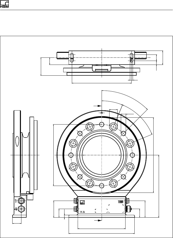
Dimensions | Abmessungen
T40B A3452-10.0 125
15.2.11T40B 10kNm, Option 7, Code S
(22)
(57)
∅196
28
190 9
12
44
20
27
53
27
53
210
152
199
∅26
M16
22,5°
45°
8 x 45° = 360°
45°
∅240
7,5
A
A
Mounting
dimensions
Dimensions in mm (1 mm = 0.03937 inches) | Abmessungen in mm
Montagemaß
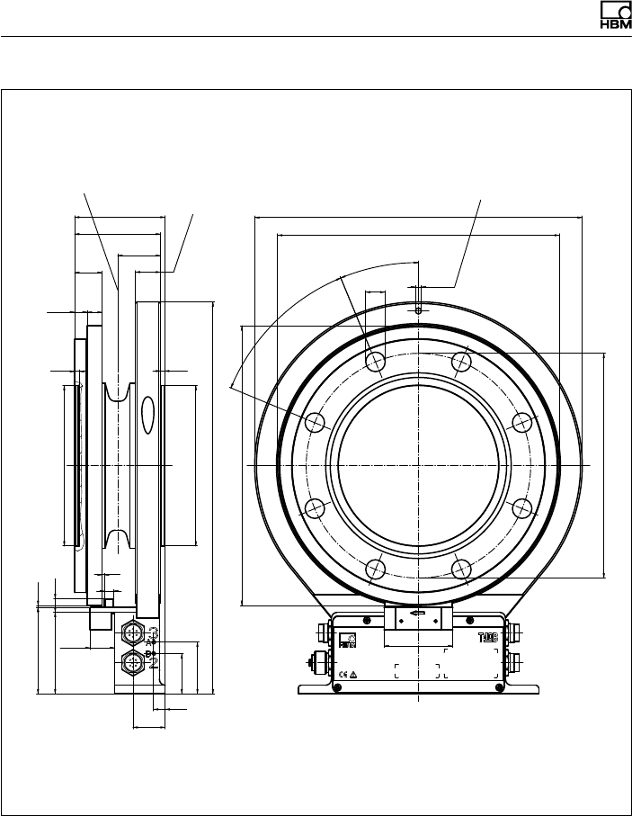
Dimensions | Abmessungen
126 A3452-10.0 T40B
C12
∅196
37,4
60
∅5,2
∅17
22,5°
8 x 45° =
360°
45°
∅244
10
28
35
45
71
(75,4)
21,5
1,6
342
139,986
139,968
∅140 g5 ()
3,5
4,2
(11) 13
24 22
75
79 ∅286
∅246
8
2
12 140,025
140,000
∅140 H6 ()
Dimensions in mm (1 mm = 0.03937 inches) | Abmessungen in mm
Schwerpunkt Zur Axialsicherung
Entspricht Statorring, wie Mess
körperflansch (Einschraubtiefe)
Ausbruch Innenzentrierung
im Schnitt A-A
Corr. to stator ring and meas.
body flange (thread reach) For axial locking
Center of gravity
Cutaway of internal centering
in section A-A
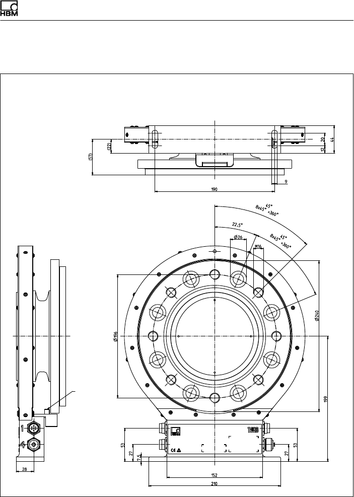
Dimensions | Abmessungen
T40B A3452-10.0 127
15.2.12T40B 10 kNm, Option 7, Code U
Dimensions in mm (1 mm = 0.03937 inches) | Abmessungen in mm
Screw head height (Shielding plates) = 2.5 mm |
Schraubenkopfhöhe (Abschirmungsplatten) = 2,5 mm
Montagemaß
Mounting
dimensions
Only
Option 6,
Code A
Nur
Option 6,
Code A
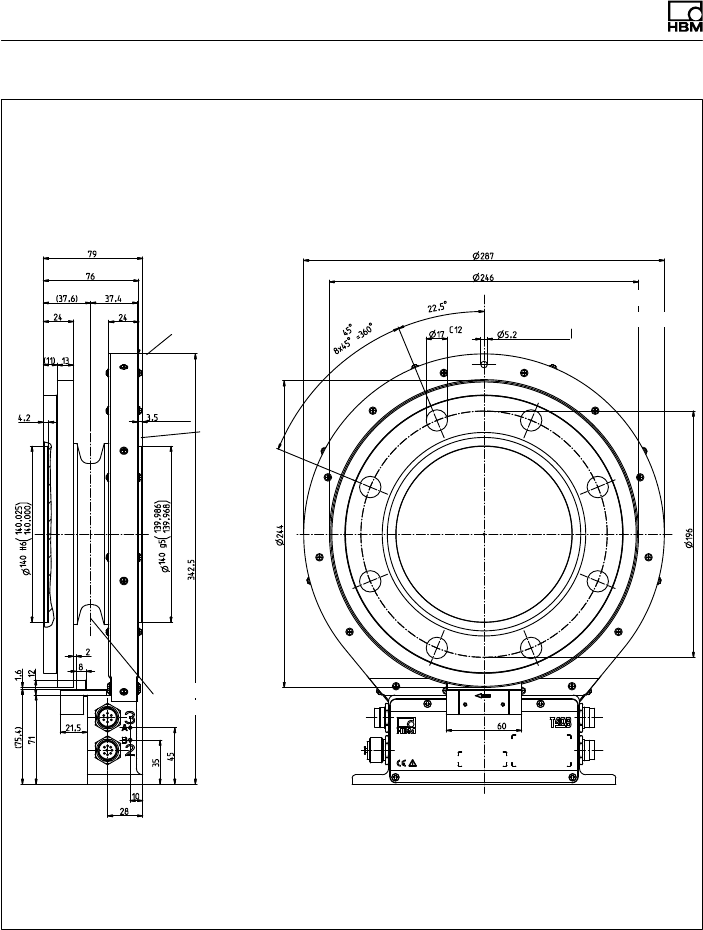
Dimensions | Abmessungen
128 A3452-10.0 T40B
Dimensions in mm (1 mm = 0.03937 inches) | Abmessungen in mm
Screw head height (Shielding plates) = 2.5 mm |
Schraubenkopfhöhe (Abschirmungsplatten) = 2,5 mm
Ausbruch Innenzentrierung
im Schnitt A-A
Cutaway of internal centering
in section A-A
Corr. to stator ring and meas. body flange
see Option 7, Code S
Entspricht Stator
ring, wie Mess
körperflansch
siehe Option 7,
Code S Zur Axialsicherung
For axial locking
Schwerpunkt
Center of gravity
External
centering
Außen
zentrierung

Dimensions | Abmessungen
T40B A3452-10.0 129

www.hbm.com
HBM Test and Measurement
Tel. +49 6151 803-0
Fax +49 6151 803-9100
info@hbm.com
measure and predict with confidence
A3452-10.0