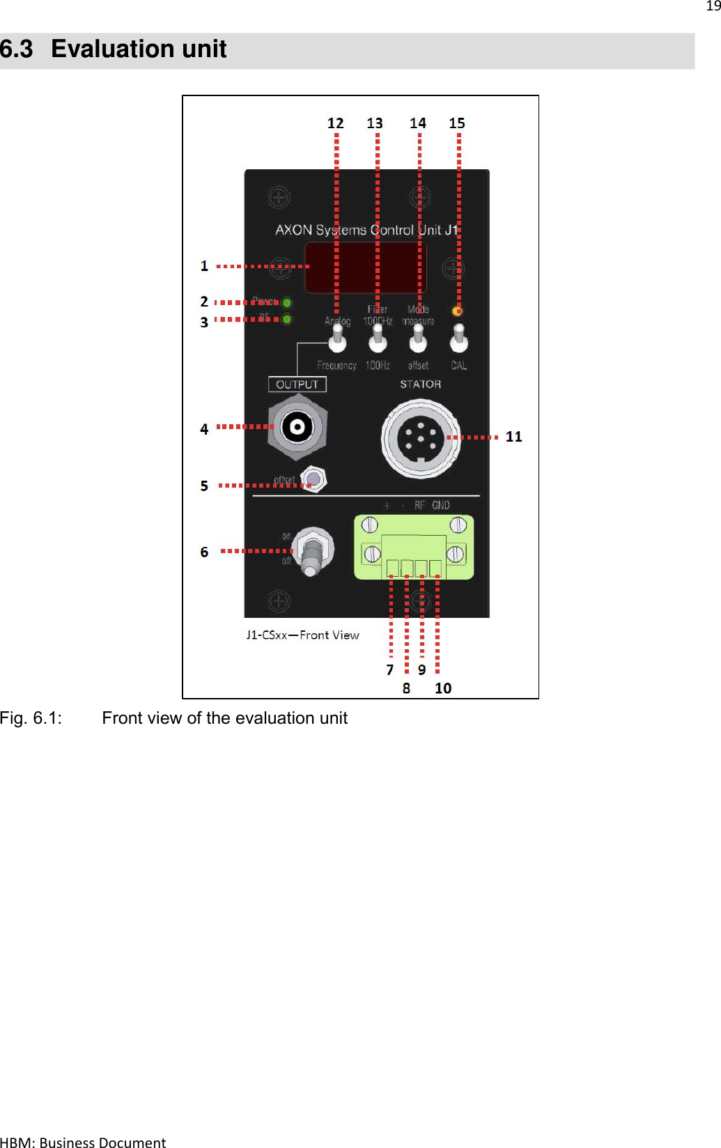
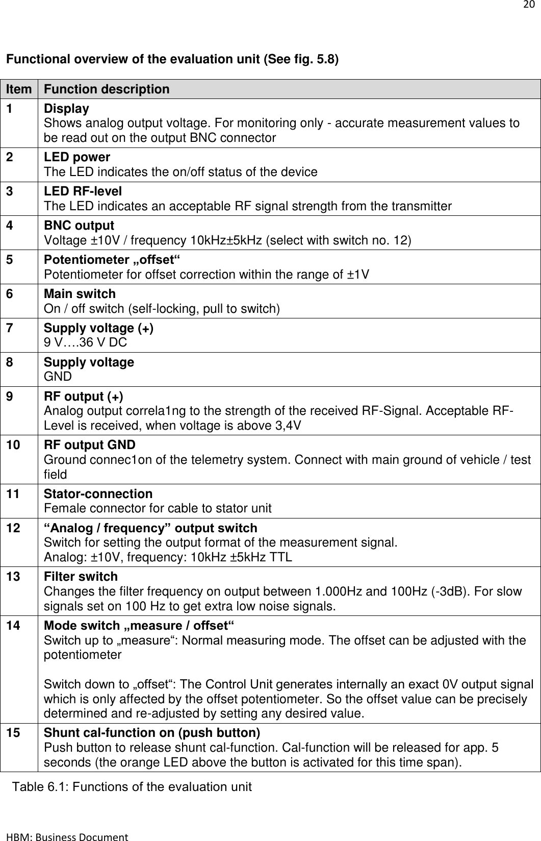
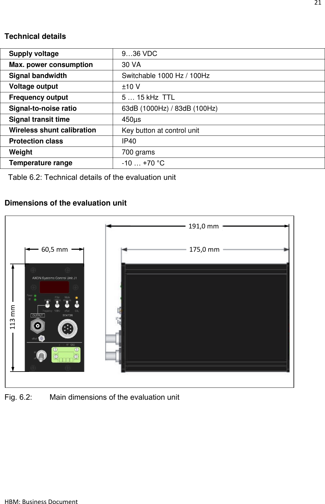
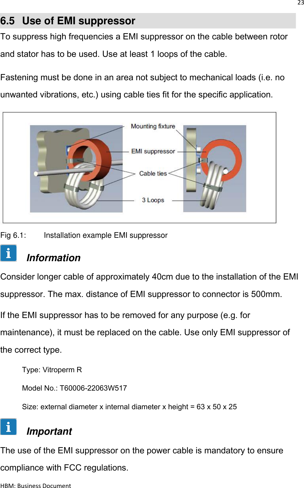
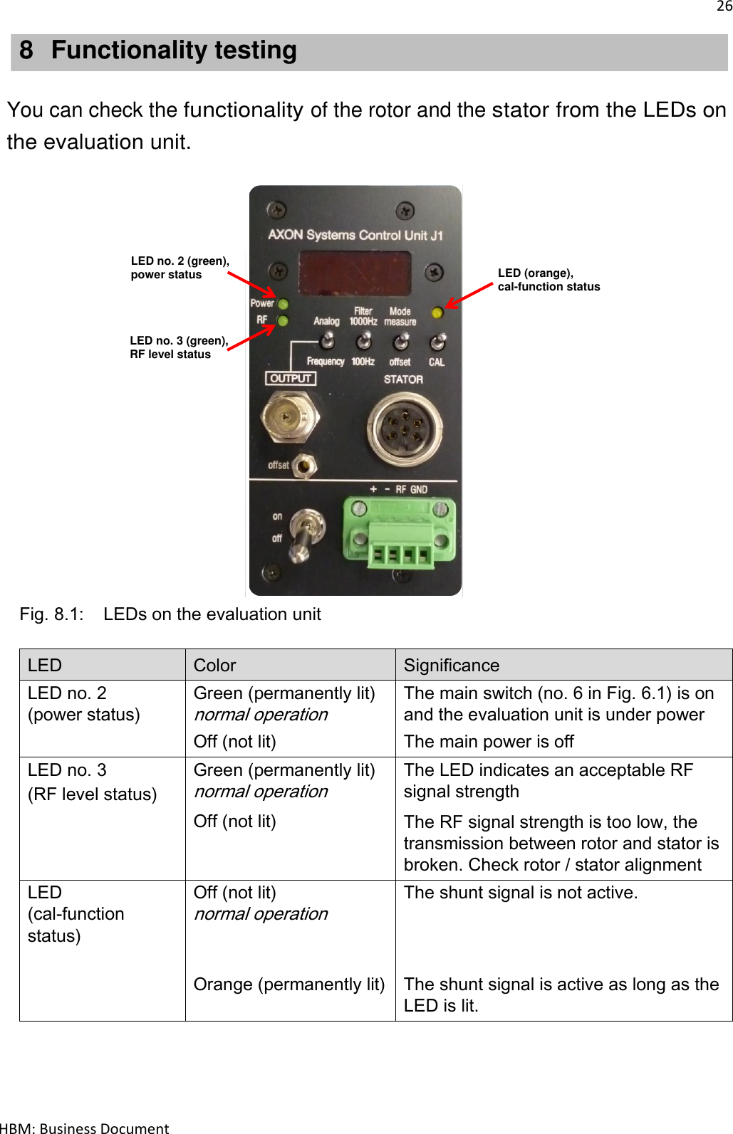
Hottinger Bruel and Kjaer TCAS5 TCA Torquemeter User Manual
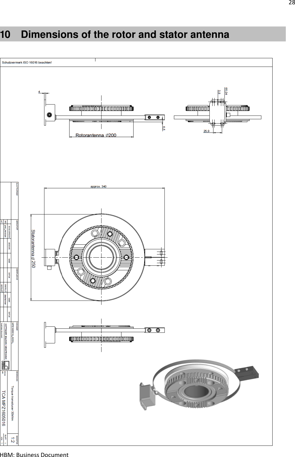
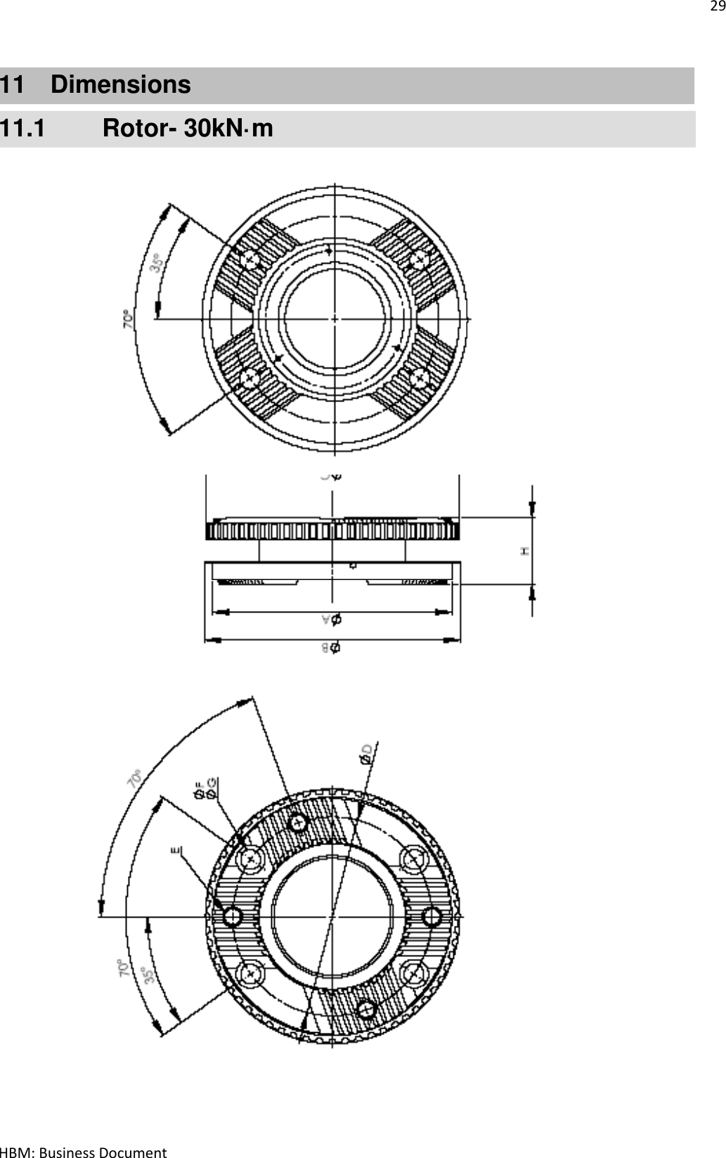
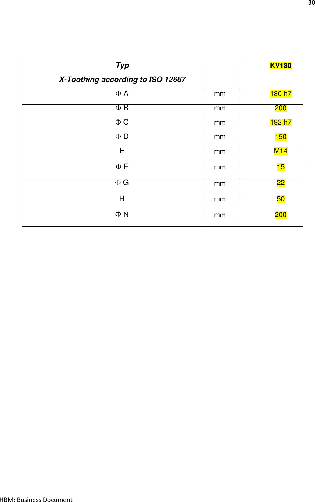
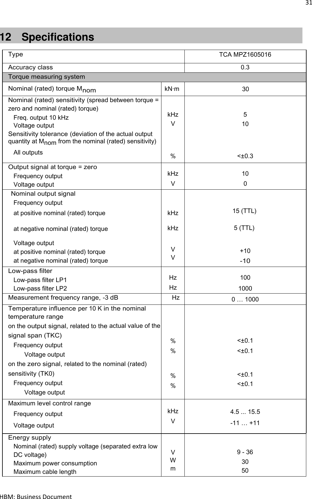
Hottinger Baldwin Messtechnik GmbH TCA Torquemeter
UserManual.wiki
>
Hottinger Bruel and Kjaer
>
TCAS5 User Manual
User Manual
Navigation menu
Upload a User Manual
Namespaces
Wiki Guide
HTML
PDF
Info
Views
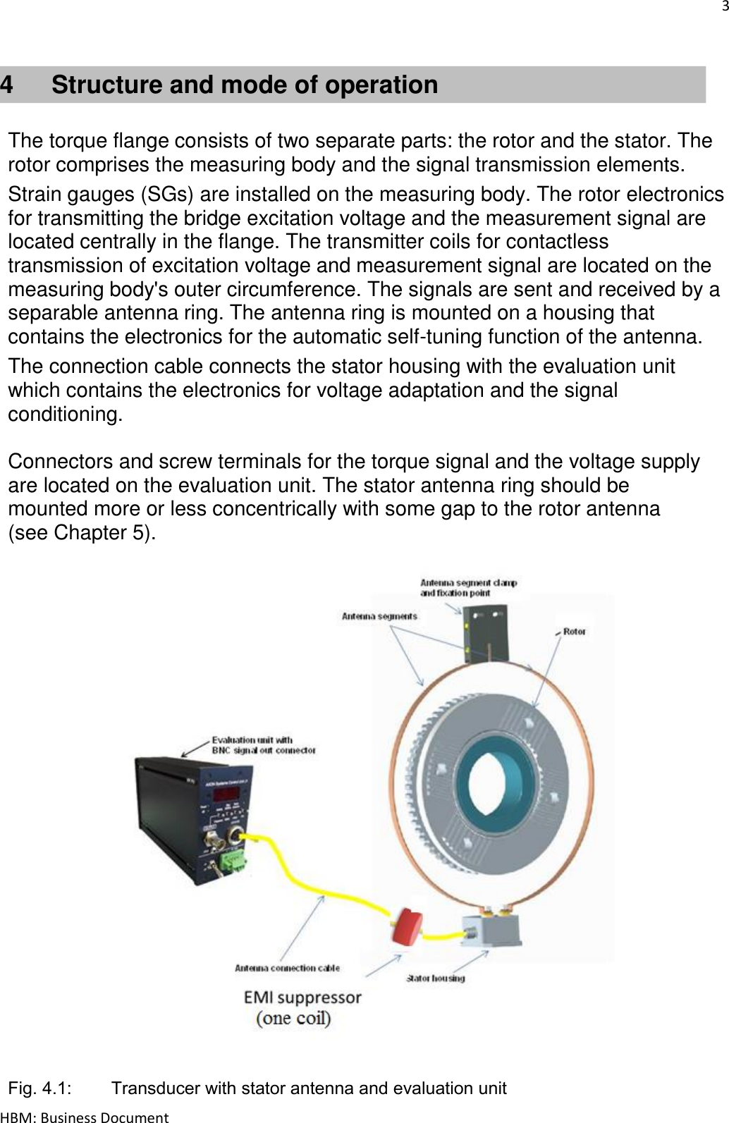
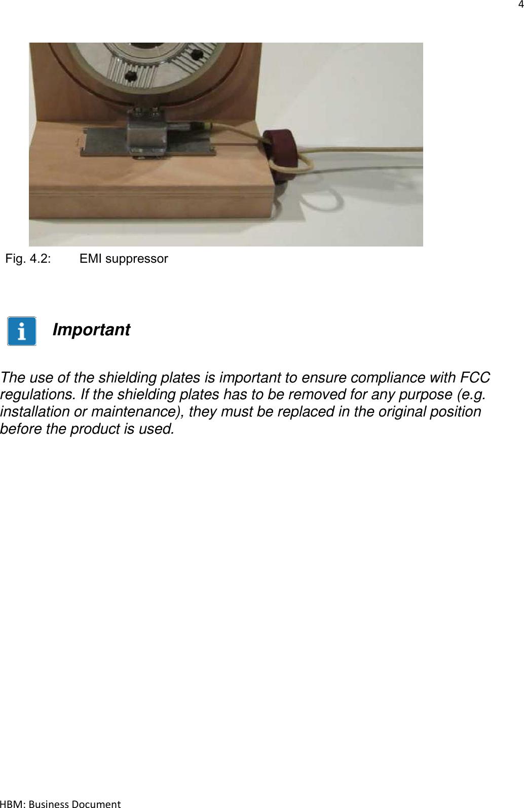
User Manual
Discussion / Help
Navigation