Hp 1105 All In One Desktop Pc Reference Guide Elwood2 AIO IPSM
2015-01-05
: Hp Hp-1105-All-In-One-Desktop-Pc-Reference-Guide-141192 hp-1105-all-in-one-desktop-pc-reference-guide-141192 hp pdf
Open the PDF directly: View PDF ![]() .
.
Page Count: 3
HP Pro 1105 Series
All-in-One Business PC 713370-003 page 1
Illustrated Parts & Service Map
HP Pro 1105 Series All-in-One Business PC
© 2013 Hewlett-Packard Development Company, L.P. The information con-
tained herein is subject to change without notice. HP shall not be liable for
technical or editorial errors or omissions contained herein. Intel, Pentium,
Intel Inside, and the Intel logo are trademarks or registered trademarks of the
Intel Corporation and its subsidiaries in the U.S. and other countries.
Document Number 713370-003. 3rd Edition March 2013.
Key Specifications
Spare Parts
Processor Type AMD Dual Core E1-1200 (1.40 GHz, 1 MB L2 cache)
RAM Type PC3-10600 DDR3, 1333 MHz, non-ECC SDRAM
Maximum RAM Supported 8 GB (2 SODIMM slots)
Display 18.5-inch, HD, anti-glare, non-touch
Expansion Slots (1) Mini PCIe x1, half-height
Graphics Adapter Integrated ATI Radeon HD 7310
Microsoft® DirectX® 11 capable
Chipset AMD A68 FCH
Drive Support (1) 5.25-inch Slimline, (1) 3.5-inch hard drive
I/O Interfaces Side: (2) USB 3.0, (1) microphone in, (1) headphone
out, (1) 6-in-1 card reader
Rear: (4) USB 2.0, (1) Power connector, (1) RJ-45
Ethernet, (1) Stereo audio line out
Operating Systems Windows 8 Professional 64-bit
Windows 8 64-bit
FreeDOS
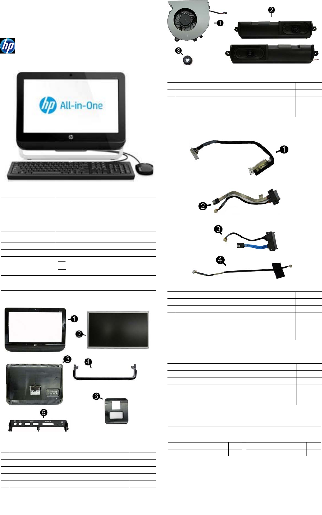
System Unit
1 Front bezel 710542-001
Display panel, 18.5-inch, CCFL, non-ZBD, 200 nits
2 AUO 710538-001
* CMO 710539-001
* LG 710540-001
3 Rear cover (does not include stand) 669985-001
4 Foot assembly 669986-001
5 Side I/O cover assembly, USB 3.0 710543-001
6 Stand 669988-001
* Mylar, for use on stand hinge 669994-001
* Not shown
Miscellaneous Parts
1 Fan (blower) 669981-001
2 Speaker kit, includes left and right speakers 678227-001
3 Rubber grommet for use in the hard drive cage 669991-001
* Mouse, USB, optical 596410-001
* HP Business Digital Headset 642738-001
*Not shown
Cables
1 LVDS cable 669996-001
2 Optical drive cable 669998-002
3 Hard drive cable 669997-001
4 Webcam cable 669995-001
* Antenna 669974-001
* Backlight cable for use with AUO and CMI display panels 710536-001
* Backlight cable for use with LG display panels 710537-001
Mass Storage Devices (not illustrated)
HP SuperMulti DVD Writer Drive (includes bezel) 657958-001
1 TB hard drive 621418-001
750 GB hard drive 632938-001
500 GB hard drive 621421-001
320 GB hard drive 621420-001
250 GB hard drive 621419-001
Keyboards (not illustrated)
Jade, wired, USB
Wireless, OTP (-201 only)
Wireless (-161 only)
655571-xx1
678360-xx1
708630-xx1
Brazilian Portuguese -201 U.S. -001
Latin America Spanish -161
HP Pro 1105 Series
All-in-One Business PC 713370-003 page 2
*not illustrated
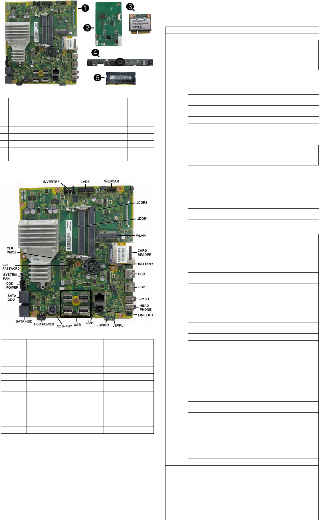
System Board
System Setup and Boot
Access the Setup Utility during computer boot by pressing the F10 key. If you do not
press F10 at the appropriate time, you must restart the computer and again press F10
when the monitor light turns green. NOTE: Not all settings are available for all models.
Boards. memory processors
1 System board with AMD E1-1200 processor, USB 3.0 (includes
heat sink, gasket, processor, replacement thermal material) 703642-001
2 Backlight controller 710541-001
3 Ralink RT3290LE 802.11bgn 1x1 Wi-Fi and Bluetooth 4.0 Combo
Adapter (WLAN module) 701399-001
* Ralink RT5390R 802.11bgn 1x1 Wi-Fi Adapter (WLAN module) 701396-001
4 Webcam module, 720p HD 710544-001
5 4-GB memory module (PC3-12800, SODIMM) 689373-001
* 2-GB memory module (PC3-12800, SODIMM) 689372-001
* 1-GB memory module (PC3-10600, SODIMM) 646808-001
System Board Components
INVERTER Inverter board connector JSPKL1 Left speaker connector
LVDS Display connector JSPKR1 Right speaker connector
WEBCAM Webcam connector LAN1 RJ-45 network connector
JDDR2 Memory slot, channel B USB USB port
JDDR1 Memory slot, channel A DC INPUT AC power connector
WLAN Mini PCIe slot
HDD POWER
Hard drive power connector
CARD
READER Card reader SATA HDD Hard drive data connector
BATTERY RTC battery slot SATA ODD
Optical drive data connector
USB USB ports ODD PWR
Optical drive power connector
JMIC1 Microphone (line in)
connector
SYSTEM FAN
Fan connector
HEAD-
PHONE Headphone (line out)
connector CLR_
PASSWORD Password jumper
LINE OUT Line out connector CLR_CMOS CMOS jumper
Computer Setup Menu
Heading Option/Description
File System Information - Lists the following main system specifications:
• Product name
• SKU number (some models)
• Processor type/speed/stepping
• Cache size (L1/L2/L3)
• Installed memory size/speed/ch
• Integrated MAC Address
• System BIOS
• Chassis serial number
• Asset tracking number
• ME firmware version
• ME management mode
About - Displays copyright notice.
Set Time and Date - Allows you to set system time and date.
Replicated Setup - Allows you to save or restore system configuration to/
from a USB flash drive.
Default Setup - Allows you to save current settings as default or restore
factory settings as default.
Apply Defaults and Exit - Applies the selected default settings and clears
any established passwords.
Ignore Changes and Exit - Exits Computer setup without saving changes.
Save Changes and Exit - Saves changes to system configuration or
default settings and exits Computer Setup.
Storage Device Configuration - Lists all installed BIOS-controlled storage
devices. The following options are available:
• CD-ROM
• Hard Disk
• Default Values
• Translation Mode
• SSD Life Used
• SMART (ATA disks only)
• Diskette
•SATA Defaults
Storage Options - Allows you to set:
• eSATA Port - Set SATA port as eSATA port for use with external drive.
• SATA Emulation - Choose how the SATA controller and devices are
accessed by the OS. SATA Emulation choices are AHCI, RAID, or IDE.
• Removable Media Boot - Enables/disables ability to boot the system
from removable media.
• Max eSATA Speed - Allows you to choose 1.5 Gbps or 3.0 Gpbs as
the maximum eSATA speed. By default, the speed is limited to 1.5
Gbps for maximum reliability.
DPS Self-Test - Execute self-tests on ATA hard drives capable of per-
forming the Drive Protection System (DPS) self-tests.
Boot Order - Specify boot order for UEFI and legacy boot sources. Also
specify hard drive boot order.
• Shortcut to Temporarily Override Boot Order
Security
Setup Password - Set and enable the setup (Admin) password.
Power-On Password - Set and enable power-on password.
Password Options - Allows to you enable/disable:
• Lock Legacy Resources
• Setup Browse Mode
• Password prompt on F9 & F12
• Network Server Mode
Smart Cover - Allows you to lock/unlock the smart cover and set the
cover removal sensor to disable/notify user/setup password.
Device Security - Set Device Available/Device Hidden for: embedded security
device, system audio, network controller, USB controller, serial/parallel ports,
and SATA ports.
USB Security - Set Device Available/Device Hidden for front USB ports,
rear USB ports, internal USB ports, accessory USB ports.
Slot Security - Disable the PCI, PCIe, and Mini Card slots.
Network Boot - Enables/disables boot from OS (NIC models only).
System IDs - Allows you to update asset tag, ownership tag, UUID, key-
board locale setting.
Master Boot Record Security - enables/disables MBR.
System Security - Allows you to set:
• Data Execution Prevention (enable/disable)
• SVM CPU Virtualization (enable/disable).
• Virtualization Technology (VTx) (enable/disable)
• Virtualization Technology/Directed IO (VTd) (enable/disable)
• Trusted Execution Technology (enable/disable)
• Embedded Security Device (enable/disable)
• Reset to Factory Settings (Do not reset/Reset)
• Measure boot variables/devices to PCR1 (enable/disable)
• OS management of Embedded Security Device (enable/disable)
• Reset of Embedded Security Device through OS (enable/disable)
• No PPI provisioning (Windows 8 only; enable/disable)
• Allow PPI policy to be changed by OS (enable/disable)
DriveLock Security - Allows you to assign or modify a master or user
password for hard drives.
Secure Boot Configuration (Windows 8 only)
• Legacy Support (enable/disable)
• Secure Boot (enable/disable).
• Key Management (enable/disable)
• Fast Boot (enable/disable)
Power OS Power Management - Allows you to enable/disable Runtime Power
Management, Idle Power Savings, Unique Sleep State Blink Rates.
Hardware Power Management - Enable/disable SATA power management,
S5 maximum power savings., PCI slots, network controller, USB 3.0 controller
Thermal - Control minimum fan speed.
Advanced Power-On Options - Allows you to set:
• POST mode (QuickBoot, Clear Memory, FullBoot, or FullBoot Every x Days)
• POST messages (enable/disable)
• Press the ESC key for Startup Menu (enable/disable)
• Option ROM Prompt (enable/disable)
• After Power Loss (off/on/previous state)
• POST Delay (none, 5, 10, 15, 20, or 60 seconds)
• Remote Wakeup Boot Source (remote server/local hard drive)
• Factory Recovery Boot Support (enable/disable)
• Bypass F1 Prompt on Configuration Changes (enable/disable)
BIOS Power-On - Set the computer to turn on at a preset time.

HP Pro 1105 Series
All-in-One Business PC 713370-003 page 3
Password Security and CMOS
Establishing a Setup or Power-On password
1. Turn on or restart the computer.
2. As soon as the computer turns on, press the Esc key while “Press the ESC key for
Startup Menu” message is displayed at the bottom of the screen.
3. Press the F10 key to enter Computer Setup.
4. To establish Setup password, select Security > Setup Password and follow the
instructions.
- or -
To establish a Power-On password, select Security > Power-On Password and
follow the instructions on the screen
5. Before exiting, click File > Save Changes and Exit.
Resetting a Setup or Power-On password
1. Turn off the computer and disconnect the power cord from the power outlet.
2. Remove the access panel.
3. On the system board, locate the header labeled CLR PASSWORD.
4. Remove the jumper and place it on pins 1 and 2.
5. Wait for three seconds, and then replace the jumper to its original position (pins 2
and 3).
6. Replace the access panel and reconnect the power cord.
7. Turn on the computer and allow it to start.
Resetting CMOS
1. Turn off the computer and disconnect the power cord from the power outlet.
2. Remove the access panel.
3. On the system board, locate the header labeled CLR CMOS.
4. Remove the jumper and place it on pins 2 and 3.
5. Wait for three seconds, and then replace the jumper to its original position (pins 1
and 2).
6. Replace the access panel and reconnect the power cord.
7. Turn on the computer and allow it to start.
Advanced
(continued)
Bus Options - Allows you to enable/disable PCI SERR# Generation and
PCI VGA palette snooping.
Onboard Devices - Allows you to set resources for or disable on-board
system devices.
Device Options - Allows you to set:
• Printer mode (Bi-Directional, EPP + ECP, Output Only)
• Num Lock State at Power-on (off/on)
• Integrated Video (enable/disable)
• Integrated Graphics (Auto/Disable/Force)
• Internal Speaker (enable/disable)
• NIC PXE Option ROM Download (enable/disable)
• SATA RAID Option ROM Download (enable/disable)
• Multi-Processor (enable/disable)
• Hyper-threading (enable/disable)
• Turbo Mode (enable/disable)
VGA Configuration - Allows you to specify which VGA controller is the
“boot”/primary. Displayed only if add-in video card installed.
AMT Configuration - Allows you to set:
• AMT (enable/disable)
• Unconfigure AMT/ME (enable/disable)
• Hide Unconfigure ME Confirmation Prompt (enable/disable)
• Watchdog Timer (enable/disable)
Common POST Error Messages
Screen
Message Probable Cause Recommended Action
101-Option ROM
Error System ROM or expansion
board option ROM check-
sum.
1. Verify ROM, reflash if required
2. Remove recently added cards to see if
problem remains.
3. Clear CMOS. If message disappears, may
be card problem.
4. Replace system board
103-System Board
Failure DMA or timers 1. Clear CMOS memory.
2. Remove expansion boards.
3. Replace system board.
163-Time & Date
Not Set Invalid time or date in con-
figuration memory.
RTC battery may need to be
replaced.
Reset the date and time under Control Panel
(Computer Setup can also be used). If the
problem persists, replace the RTC battery.
164-Memory Size
Error Memory amount has
changed since the last boot
(memory added/removed).
Press the F1 key to save the memory changes.
164-Memory Size
Error Incorrect memory configura-
tion 1. Run Setup (F10).
2. Make sure memory module(s) installed
properly.
3. If third-party memory added, test using HP-
only memory.
1. Verify proper module type.
201-Memory Size
Error RSM failure 1. Ensure memory modules are correctly
installed.
2. Verify proper module type.
3. Remove and replace faulty module(s).
4. If error persists after replacing modules,
replace system board.
214-DIMM Config-
uration Warning Populated DIMM configura-
tion is not optimized Rearrange DIMMs so that each channel has
the same amount of memory.
219-ECC Memory
Module Detected
ECC Modules not
supported on this
Platform
Recently added memory
module(s) support ECC
memory error correction.
1. If additional memory was recently added,
remove it to see if the problem remains.
2. Check product documentation for memory
support information.
301-, 304-Key-
board error Keyboard failure. 1. Reconnect keyboard with system turned off.
2. Check kybd connection or keys.
3. Check connector for bent or missing pins.
4. Replace keyboard.
5. If 304, possible sys bd problem.
511-CPU Fan not
Detected CPU Fan not Detected. 1. Reseat CPU fan.
2. Reseat fan cable.
3. Replace CPU fan.
1805-Ambient
Temperature Pre-
viously Over Limit
This system was placed in a
low power state to prevent
damage due to excessive
environmental temperature.
Make sure the system meets the HP enclosure
guidelines as listed in the Quick Specs, includ-
ing the following:
1. Clean the air vents on the front, back, or any
other vented side of the computer.
2. Ensure that there is a 10.2 cm (4 in)
clearance on all vented sides of the
computer to permit the required airflow.
3. Ensure that computers are not so near each
other that they are subject to each other's
re-circulated or preheated air.
2200-PMM Alloca-
tion Error during
MEBx Download
2201-MEBx Mod-
ule did not check-
sum correctly
2202-PMM Deallo-
cation Error during
MEBx cleanup
(2200) Memory error during
POST execution of the Man-
agement Engine (ME) BIOS
Extensions option ROM.
(2201) Memory error during
POST execution of the Man-
agement Engine (ME) BIOS
Extensions option ROM.
(2202) Memory error during
POST execution of the Man-
agement Engine (ME) BIOS
Extensions option ROM.
1. Reboot the computer.
2. Unplug the power cord, re-seat the memory
modules, and reboot the computer.
3. If the memory configuration was recently
changed, unplug the computer, restore the
original memory configuration, and reboot
the computer.
4. If the error persists, replace the system
board.
2230-General
error during MEBx
execution
2231-ME error dur-
ing MEBx execu-
tion
2232-AMT error
during MEBx exe-
cution
2233-HECI error
during MEBx exe-
cution
(2230) Error occurred during
MEBx execution which fails
into the “General” grouping.
Status information displayed
along with the error provides
further clarity into the failure.
MEBx handles transference
of information between the
system BIOS and ME firm-
ware.
(2231) Error occurred during
MEBx execution which fails
into “ME” grouping.
(2232) Error occurred during
MEBx execution which fails
into “AMT” grouping.
(2233) Error occurred during
MEBx execution which fails
into “MEI or HECI” grouping.
1. Reboot the computer.
2. If the error persists, update to the latest
BIOS version and ME firmware version.
3. If the error still persists, replace the system
board.
