Hp 500B Microtower Pc Service And Maintain MT IPSM_Fall10
2015-01-05
: Hp Hp-500B-Microtower-Pc-Service-And-Maintain-141241 hp-500b-microtower-pc-service-and-maintain-141241 hp pdf
Open the PDF directly: View PDF ![]() .
.
Page Count: 3
HP 500B, MT 635950-001 page 1
Illustrated Parts & Service Map
HP 500B MT Business PC
© 2010 Hewlett-Packard Development Company, L.P. The information con-
tained herein is subject to change without notice. HP shall not be liable for
technical or editorial errors or omissions contained herein.
Document Number 635950-001. 1st Edition September 2010.
Key Specifications
Spare Parts
Processor Type Intel Celeron, Intel Pentium dual-core
RAM Type DDR3-SDRAM DIMMs, PC3-10600 (1333 MHz)
Maximum RAM Supported 4 GB (2 x 2 GB)
Expansion Slots • 1 full-height PCI 2.3 slot
• 2 full-height PCIe x1 slots
• 1 full-height PCIe x16
Graphics Adapter Intel Graphics Media Accelerator X4500
Chipset Intel G41 Express
Drive Support • (1) 5.25-inch external optical drive bay
• (1) 3.5-inch internal hard disk drive bay
I/O Interfaces (8) USB 2.0 ports: (2) front ports, (4) rear ports, (2) internal
ports on motherboard; (1) RJ-45, (1) VGA, (1) front audio in,
(1) front audio out, (1) rear audio in, (1) rear audio out, (1) rear
microphone
Operating Systems • Windows 7
• Windows Vista
• Windows XP
• FreeDOS
• Novell SUSE Linux
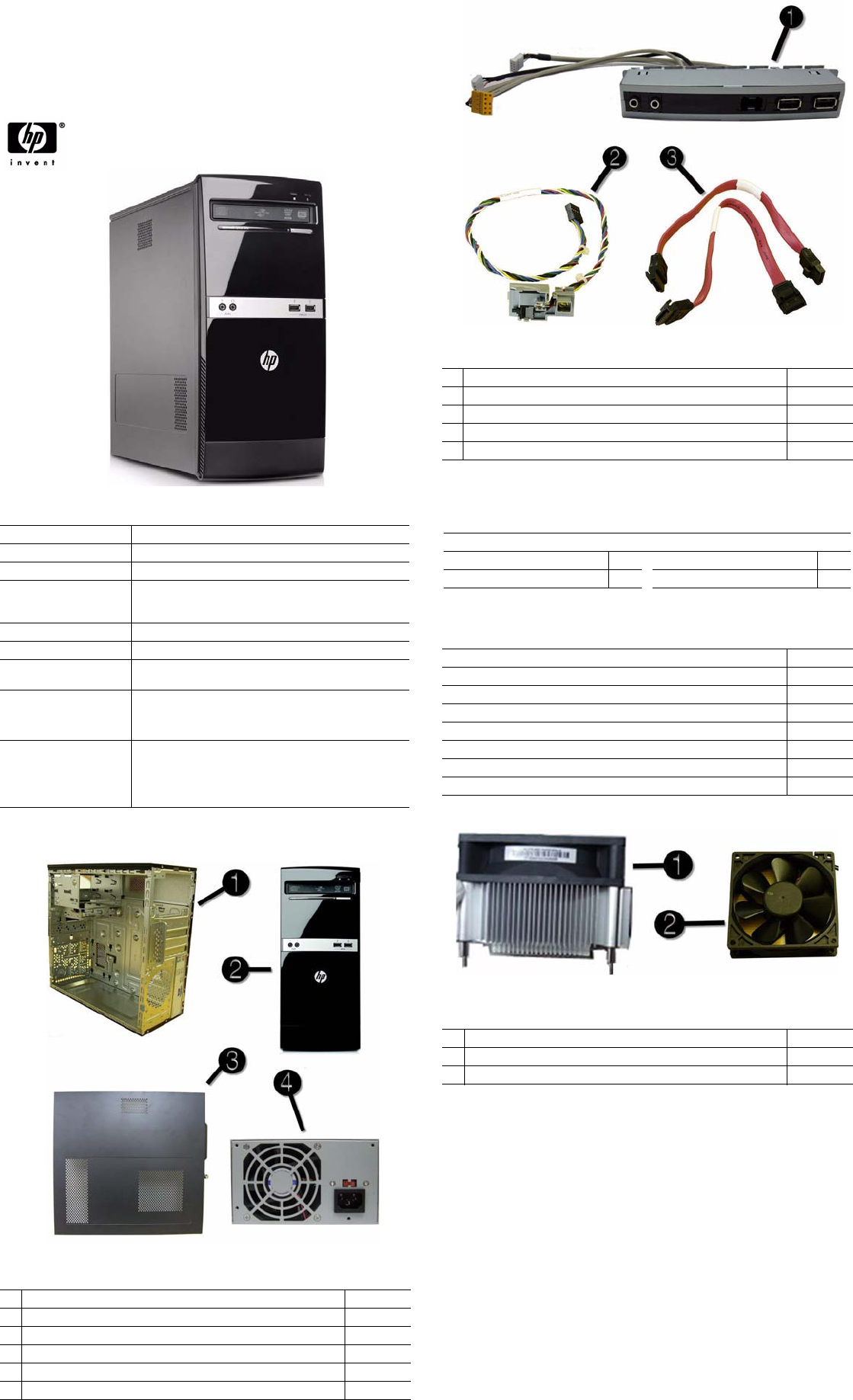
System Unit
1 Chassis Not spared
2 Front bezel without card reader 616792-001
3 Access panel 616791-001
* Thumbscrew for use on access panel 448665-001
4 Power supply, 300W, non-PFC 463318-001
* 5.25-inch bezel blank 586749-001
* Not shown
Cables
1 Front I/O assembly without card reader 586729-001
2 Power switch/LED cable assembly 586724-001
3 SATA HDD cable, 6.5 inch, with latch 448670-001
* PATA to SATA adapter 449283-001
* DMS-59 to dual DVI cable 463024-001
*Not shown
Keyboards (not illustrated)
USB, blue 537924-xxx
French Canadian -121 Latin American Spanish -161
International English -L31 United States -001
Mass Storage Devices (not illustrated)
16X DVD±RW SuperMulti drive with LightScribe 581059-001
16X DVD-ROM drive 581599-001
750 GB hard drive 613205-001
640 GB hard drive 613204-001
500 GB hard drive 586720-001
320 GB hard drive 586969-001
250 GB hard drive 586719-001
160 GB hard drive 586718-001
Miscellaneous Parts
1 Heat sink, Intel class F (includes thermal material) 616411-001
2 Chassis fan 449207-001
* Mouse, optical, carbon 444740-001
*Not shown
HP 500B, MT 635950-001 page 2
System Board
Diagnostic Beep Codes
The Power-On Self-Test (POST) is a series of diagnostic tests that runs automatically when the
computer is powered on. If the POST detects an error, this causes an audible beep code to sound.
The POST beep codes are not necessarily accompanied by an associated, visible error code or
text message.
The following table shows the POST beep codes, their meanings, and the recommended actions
for solving the problem.
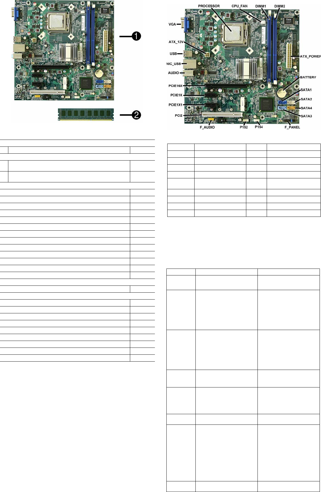
Standard and Optional Boards
System boards with thermal grease, alcohol pad, and CPU socket cover
1 System board 616409-001
Memory modules
2 2 GB, PC3-10600 629026-001
576110-001
2 1 GB, PC3-10600 629025-001
576109-001
Other boards
LSI 56K modem, PCIe 490689-001
HP Wireless 802.11b/g/n WLAN card 538048-001
802.11b/g/n WLAN card, for use in ROW 498307-001
ATI Radeon HD4350 (RV710) PCIe x16 graphics card, 512 MB 586750-001
ATI Radeon HD5450 PCIe graphics card, 1 GB 601155-001
ATI Radeon HD5450 PCIe graphics card, 512 MB 617079-001
GeForce G315, PCIe graphics card, 1 GB 619934-001
GeForce G320, PCIe graphics card, 1 GB 615793-001
GeForce G210, PCIe graphics card, 512 MB 586382-001
Intel Gigabit NIC, includes bracket 490367-001
HP FireWire IEEE 1394 PCI card, FH 515182-001
1394 PCI card, 3 port, FH 441448-001
Antenna, dual band, 802.11 583345-001
Intel Celeron Processors with alcohol pad and thermal grease:
E3400, 1-MB cache, 2.60 GHz 602071-001
Intel Core2 Duo Processors with alcohol pad and thermal grease:
E7600, 3-MB cache, 3.06 GHz 573954-001
E7500, 3-MB cache, 2.93 GHz 531988-001
E6800, 2-MB cache, 3.33 GHz 631758-001
E6700, 2-MB cache, 3.20 GHz 418950-001
E6600, 2-MB cache, 3.06 GHz 602070-001
E6500, 2-MB cache, 2.93 GHz 586748-001
E5700, 2-MB cache, 3.00 GHz 631759-001
E5500, 2-MB cache, 2.80 GHz 613035-001
E5400, 2-MB cache, 2.70 GHz 586743-001
System Board Connectors and Jumpers (position of some untitled
components may vary in location)
PROCESSOR
Processor socket
PCI2
PCI slot
CPU FAN
Fan connector
PCIE1X1
PCIe x1 slot
DIMM1-2
Memory slots
PCIE1X
PCIe x1 slot
ATX_P OWER
24-pin main power connector
PCIE16X
PCIe x16 slot
BATTERY
RTC battery socket
AUDIO
External in/out connectors
SATA0-3
Drive connectors
NIC_USB
Stacked network/USB connec-
tors
F_PANEL
Front I/O connector
USB
Stacked USB connectors
P154
Front I/O connector
AT X _ 1 2V
4-pin CPU power connector
P152
Front I/O connector
VGA
Monitor connector
F_AUDIO
Front audio connector
Diagnostic Beep Codes
Beeps Diagnosis Recommended Action
1 short, 1 long Bad memory or memory configura-
tion error
Check that the memory modules
have been installed correctly and
that proper modules are used.
2 short, 1 long No graphics card installed or graph-
ics card initialization failed.
For systems with a graphics card:
1. Reseat the graphics card. Power
on the system.
2. Replace the graphics card.
3. Replace the system board.
For systems with integrated graph-
ics, replace the system board.
3 short, 1 long CPU configuration error or invalid
CPU detected before graphics card
initialized.
For systems with a graphics card:
1. Reseat the graphics card. Power
on the system.
2. Replace the graphics card.
3. Replace the system board.
For systems with integrated graph-
ics, replace the system board.
1 short, short
pause
No legacy floppy drive or optical
drive found
1. Check cable connections.
2. Run the Setup utility and ensure
the device port is enabled.
2 short, long
sec pause
No floppy diskette or CD found 1. Check the type of drive you are
using and use the correct media
type.
2. Replace the diskette or CD with a
new one.
3 short, long
sec pause
Flashing not ready (missing utility
or BIOS image file, etc.)
Upgrade the BIOS to proper ver-
sion.
4 short, long
sec pause
Flashing operation has failed
(checksum error, corrupted image,
etc.)
1. Verify the correct ROM.
2. Flash the ROM if needed.
3. If an expansion board was
recently added, remove it to see if
the problem remains.
4. Clear CMOS.
5. If the message disappears, there
may be a problem with the
expansion card.
6. Replace the system board.
5 short, long
sec pause
BIOS recovery was successful No action required.

HP 500B, MT 635950-001 page 3
LED Codes
The following table describes the LED states for the HP 500B, Compaq 500B, and 505B MT
Desktop PCs.
Clearing CMOS
The header allows you to clear the RTC RAM in CMOS.
To erase the RTC RAM:
1. Turn off the computer and any external devices, and disconnect power.
2. Remove the access panel.
3. Remove the RTC battery.
4. Locate the CMOS jumper header on the motherboard. It is labeled E18.
5. Remove the jumper from pins 2-3 pins and put it on pins 1-2 to clear CMOS. Keep the cap on
pins 1-2 for 5 to 10 seconds.
6. Replace the jumper on pins 2-3.
7. Reinstall the battery.
8. Replace the access panel, external devices, and reconnect the power cord.
9. Turn on the computer.
10.Hold down the F1 key during boot and enter BIOS setup to re-enter data.
Hewlett-Packard Vision Diagnostics
The Hewlett-Packard Vision Diagnostics utility allows you to view information about the hard-
ware configuration of the computer and perform hardware diagnostic tests on the subsystems of
the computer. The utility simplifies the process of effectively identifying, diagnosing, and iso-
lating hardware issues.
Use HP Vision Diagnostics to determine if all the devices installed on the computer are recog-
nized by the system and functioning properly. Running tests is optional but recommended after
installing or connecting a new device.
To access HP Vision Diagnostics, you must create a Recovery Disc Set then boot to the CD con-
taining the utility. It can also be downloaded from http://www.hp.com and either burned to CD
or installed to a USB flash drive.
1. In Windows Explorer, go to C:\SWSetup\ISOs and burn the file Vision Diagnostics.ISO to a
CD or copy it to a USB flash drive.
2. While the computer is on, insert the CD in the optical drive or USB flash drive in a USB port.
3. Shut down the operating system and turn off the computer.
4. Turn on the computer. The system will boot into HP Vision Diagnostics.
NOTE: If the system does not boot to the CD in the optical drive or to the USB flash drive,
you may need to change the boot order in the Computer Setup (F10) utility.
5. At the boot menu, select either the HP Vision Diagnostics utility to test the various hardware
components in the computer or the HP Memory Test utility to test memory only.
NOTE: The HP Memory Test is a comprehensive memory diagnostic utility that is run as a
stand-alone application, outside of HP Vision Diagnostics.
6. If running HP Vision Diagnostics, select the appropriate language and click Continue.
7. In the End User License Agreement page, select Agree if you agree with the terms. The HP
Vision Diagnostics utility launches with the Survey tab displayed.
Using the Setup Utility
The BIOS Setup Utility is accessed by pressing the F10 button during startup. The BIOS Setup
Utility allows you to:
• Change factory default settings
• Set the system date and time
• Set, view, change, or verify the system configuration, including settings for graphics, audio,
storage, communications, and input devices
• View processor and memory settings
• Modify the boot order of bootable devices, such as hard drives, diskette drives, optical
drives, or USB media
• Run tests on the hard drive
• Establish a supervisor password that controls access to the Setup Utility
Power Button/Power Button LED
The power button is under the BIOS control during POST, in BIOS Setup and after booting to a
non-ACPI OS. The BIOS must respond immediately when the power button is pressed in these
environments. For the ACPI-compliant OS such as Windows, the BIOS must pass the power
button information to the OS via the ACPI table as specified in the ACPI spec.
If a platform offers a dual-color-based power button LED, the BIOS will program the power
button LED to alternate the color between the On (ACPI S0) state and the Stand-by (S3) state. In
doing so, the LED should not blink, but stay constant. Check with the corresponding platform
manager for the default colors in the On and Stand-by states. The color of the power button LED
in the Hibernate state (ACPI S4) is the same as in the S5 state.
To find out if the system's power button LED is dual-color capable, check the SMBIOS Type 11
data structure. If the SMBIOS Type 11 data structure contains the string DLED (NOT case-
sensitive), the system supports the dual-color power button LED and therefore, the BIOS
support as described above is required.
BIOS Updates
HP periodically releases system BIOS updates, which are available from the HP web site. These
updates often contain fixes for known issues in the BIOS.
To find out whether a PC needs a BIOS update, compare the current BIOS version number
against the latest version available for download. To determine the current BIOS version, you
should perform the
following steps:
1. Click Start > Shut Down.
2. Select Restart, and then click OK.
3. When the first screen displays, press F10 to enter Setup. The BIOS revision number is listed
on the main menu.
4. Write down the current BIOS version.
5. Exit Setup by pressing Esc, selecting Ye s , and pressing Enter.
POST Error/Warning Messages
Once the display becomes available, the BIOS should classify all errors detected during POST
into 3 categories and handle them as specified below:
• Critical errors requiring system shutdown (e.g. CPU fan fault):
Clear the screen, display the corresponding error message, pause for a while as specified and
then turn the system off.
• Serious errors requiring user's attention and response (e.g. SMART error during POST):
Display the corresponding error message, wait for the user's input and then proceed as
selected.
• Alerts/warnings requiring user's attention (e.g. CMOS checksum error -> defaults loading):
Display the corresponding message and pause for a while as specified. If the message
includes an option for a keystroke from the user and the user responds with the key input,
proceed as selected. Otherwise, continue the POST process.
When there are multiple errors happened during POST, apply the following guideline:
• If multiple errors include at least one critical error, the system will shut down immediately
after handling the first critical error.
• If multiple errors do not include a critical error, handle all serious errors first, one by one,
and then proceed to alerts/warnings. For example, if the BIOS detected a SMART error
(serious error), a floppy diskette failure (serious error) and a CMOS checksum error (alert/
warning) during POST, the BIOS will handle them as follows:
For SKUs including an OS=MSV or an OS=LX in the SMBIOS Type 11 data,
1.Handle the first serious error, SMART error, as follows:
Display "xxx: Hard disk failure is imminent... Press F10 for Setup, F2 to Continue." If the
user selects F10, proceed to Setup. However, if the user selects F2, the BIOS should
proceed to step 2 below.
2.Handle the second serious error, floppy diskette failure, as follows:
Display "Floppy diskette failure... Press F10 for Setup, F2 to Continue." If the user selects
F10, proceed to Setup. However, if the user selects F2, the BIOS should proceed to step 3
below.
3.Handle the alert/warning message, CMOS checksum error, as follows:
Display "Default BIOS settings have been loaded... Press F10 for Setup, F2 to Continue”.
If the user selects F10, proceed to Setup. However, if the user selects F2, the BIOS should
proceed to step 2 below.
For all other SKUs, use F1 instead of F10 in the above handling.
NOTE: If a device fails to respond while the BIOS tries to configure the device during POST,
the BIOS must not make the system look as if it locked up by having an infinite loop or waiting
for too long. Instead, the BIOS must time out after a reasonable amount of time (the time varies
with the device) and skip to the next process.
NOTE: Unless specified in this document as above, the BIOS should not stop the POST process
with any POST diagnostic screen and/or error message to draw user’s attention. For example,
HP does not consider replacing a hard drive or CPU as an error condition.
LED Codes
LED State LED Status
Power LED indicator System on (normal operation) Steady green
Suspend to RAM. Blinks green every 2 seconds
Computer off LED not on
Drive LED indicator Normal hard drive activity Green drive LED is flashing
