Hp Compaq Pro 4300 All In One Desktop Pc Series Reference Guide Ike IPSM_Win8
2015-01-05
: Hp Hp-Compaq-Pro-4300-All-In-One-Desktop-Pc-Series-Reference-Guide-147683 hp-compaq-pro-4300-all-in-one-desktop-pc-series-reference-guide-147683 hp pdf
Open the PDF directly: View PDF ![]() .
.
Page Count: 3
HP Compaq Pro 4300 AIO 700498-003 page 1
Illustrated Parts & Service Map
HP Compaq Pro 4300 All-in-One Business PC
© 2012, 2013 Hewlett-Packard Development Company, L.P. The infor-
mation contained herein is subject to change without notice. HP shall not
be liable for technical or editorial errors or omissions contained herein.
Intel, Pentium, Intel Inside, and the Intel logo are trademarks or regis-
tered trademarks of the Intel Corporation and its subsidiaries in the U. S.
and other countries.
Document Number 700498-003. 3rd Edition June 2013.
Key Specifications
Spare Parts
System Unit
Cables
Processor Type Intel® Core™ i7, i5, i3, Pentium®, Celeron®
Form Factor All-in one desktop, 20-inch, non-touch screen
RAM Type
PC3-10600 (1333 MHz) Non-ECC SDRAM
Maximum RAM 16 GB (2 slots)
Expansion Slot (1) half height Mini PCIe x1
Power 150W external
Chipset Intel H61 Express
Graphics Adapter Integrated Intel HD Graphics: Basic, 2000, 2500 or 4000
(depends on processor)
Drives (1) optical drive, (1) hard drive
I/O Interfaces Side: (2) USB 2.0 ports, microphone, headphone
Rear: (4) USB 2.0 ports, stereo audio out, RJ-45 Ether-
net, serial RS-232, power connector
Preinstalled Operating
Systems Windows 8
Windows 7
FreeDOS
Mass Storage Devices (do not include bracket; reuse existing bracket)
DVD-ROM drive 608394-001
DVD±RW drive 657958-001
1 TB, 7200 rpm SATA hard drive 613202-001
500 GB, 7200 rpm SATA hard drive 613208-001
250 GB, 7200 rpm SATA hard drive 613206-001
256 GB Solid State Drive (SSD), SATA 6.0, TCG 680020-001
256 GB Solid State Drive (SSD), SATA 2.0 661842-001
128 GB Solid State Drive 665961-001
120 GB Solid State Drive 661841-001
Keyboards (not illustrated)
Wireless
Standard, USB
HP Smart card, USB
Washable*
674314-xx1
674313-xx1
631411-xx4
613125-xx1
Brazilian Portuguese -20x South Korea -KDx
French Canadian -12x Taiwanese -ABx
India -37x Thai -28x
LA Spanish -16x U.S. -00x
People’s Republic of China
-AAx
* -001, -121 only
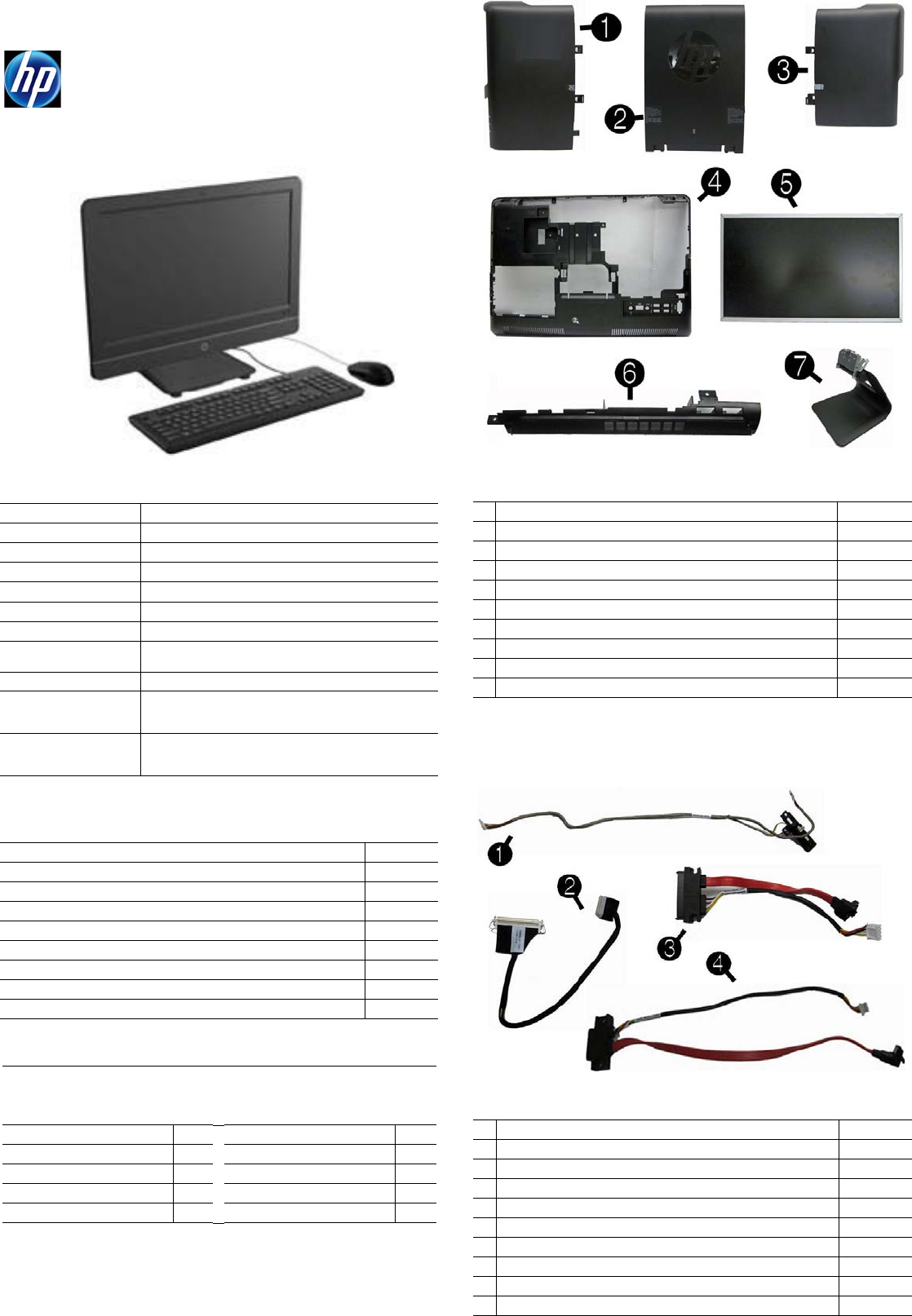
System Unit
1 Drive access panel 697335-001
2 Hinge cover panel 697338-001
3 Memory access panel 697336-001
4 Rear cover 697334-001
5 LCD assembly kit - LG, Samsung, or CMI 697341-001
6 Top panel 697337-001
7 Stand 697314-001
* Front bezel 697333-001
* Power supply, 150W, external 697317-001
* Power supply, 180W, external 697318-001
* Not shown
Cables
1 Side key cable with holder 697326-001
2 LVDS display cable 697322-001
3 Hard drive SATA cable 697325-001
4 Optical drive SATA cable 697324-001
* Converter cable 697321-001
* Webcam cable 697323-001
* Antenna, WLAN 697332-001
* Backlight cable for use with CMI display panels 697327-001
* Backlight cable for use with Samsung display panels 697328-001
* Backlight cable for use with LG display panels 697329-001
*Not shown
HP Compaq Pro 4300 AIO 700498-003 page 2
Boards
Miscellaneous Parts
Password Security and CMOS
Establishing a Setup or Power-On password
1. Turn on or restart the computer.
2. As soon as the computer turns on, press the Esc key while “Press the ESC key for
Startup Menu” message is displayed at the bottom of the screen.
3. Press the F10 key to enter Computer Setup.
4. To establish Setup password, select Security > Setup Password and follow the
instructions.
- or -
To establish a Power-On password, select Security > Power-On Password and
follow the instructions on the screen
5. Before exiting, click File > Save Changes and Exit.
Resetting a Setup or Power-On password
1. Turn off the computer and disconnect the power cord from the power outlet.
2. Remove the access panel.
3. On the system board, locate the header labeled PW.
4. Remove the jumper from the header.
5. Replace the jumper.
6. Replace the access panel and reconnect the power cord.
7. Turn on the computer and allow it to start.
Resetting CMOS
1. Turn off the computer and disconnect the power cord from the power outlet.
2. Remove the access panel.
3. On the system board, locate the header labeled CMOS.
4. Remove the jumper and place it on pins 1 and 2.
5. Wait for three seconds, and then replace the jumper to its original position (pins 2
and 3).
6. Replace the access panel and reconnect the power cord.
7. Turn on the computer and allow it to start.
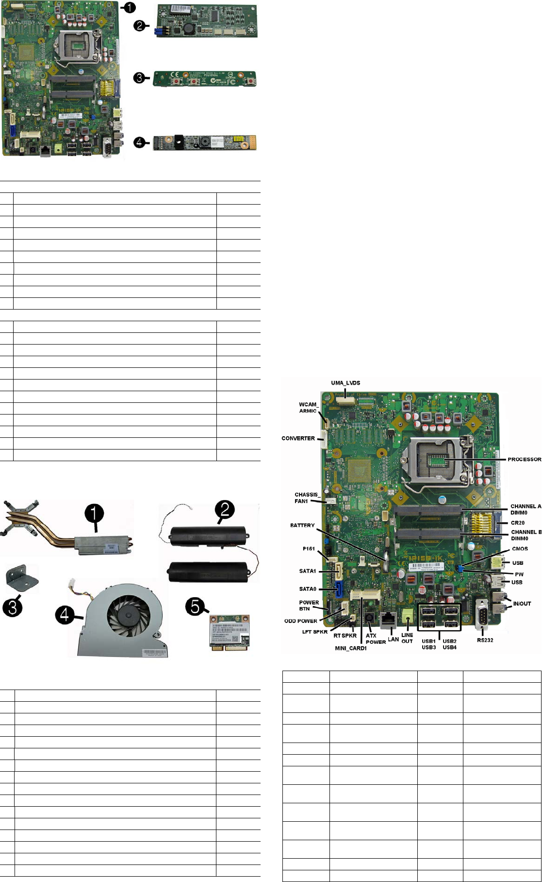
System Board
Boards, Memory, Processors
System boards (include replacement thermal material)
1 System board for use in models without Windows 8 693481-001
* System board for use in models with Windows 8 Standard 693481-501
* System board for use in models with Windows 8 Professional 693481-601
* System board for use in models with NetClone 700014-001
2 Converter board 697319-001
3 Sidekey board 663348-001
4 Webcam, 1.3MP with analog microphone 698187-001
* Memory module, 2 GB (PC3-12800, CL11, SODIMM) 689372-001
* Memory module, 4 GB (PC3-12800, CL11, SODIMM) 689373-001
* Memory module, 8 GB (PC3-12800, CL11, SODIMM) 689374-001
Processors (include replacement thermal grease)
* Intel Core i7 3770s processor, 3.1 GHz 689370-001
* Intel Core i5 3570 processor, 3.4 GHz 688162-001
* Intel Core i5 3475s processor, 2.9 GHz 695078-001
* Intel Core i5 3470s processor, 2.9 GHz 695077-001
* Intel Core i3 2130 processor, 3.4 GHz 665120-001
* Intel Core i3 2120 processor, 3.3 GHz 638629-001
* Intel Pentium Dual-Core G870 processor, 3.1 GHz 691936-001
* Intel Pentium Dual-Core G860 processor, 3.0 GHz 665123-001
* Intel Pentium Dual-Core G640 processor, 2.8 GHz 691935-001
* Intel Celeron G550 processor, 2.6 GHz 691934-001
* Intel Celeron G540 processor, 2.5 GHz 665119-001
* Intel Celeron G460 processor, 1.8 GHz 682410-001
* Not shown
Miscellaneous Parts
1
Heat sink/thermal module (includes replacement thermal material)
697315-001
2 Speaker, right 697330-001
2 Speaker, left 697331-001
3 Optical drive bracket 651600-001
4 CPU blower/fan 697320-001
5 802.11a/b/g/n WLAN PCIe card 652165-001
* Grommet, rubber, hard drive 663357-001
* Optical drive insert (for models without an optical drive) 697339-001
* Web cam cover (for models without a webcam) 697340-001
* Bluetooth 4.0 and 802.11a/b/g/n WLAN combo card 697316-001
* HP keyed cable lock 626729-002
* HP Business Digital Headset 642738-001
* Mouse, laser, USB 674318-001
* Mouse, wireless 674317-001
* Mouse, optical, USB 673416-001
* Mouse, washable 619580-001
*Not shown
System Board Connectors and Jumpers
UMA_LVDS Display panel connector
MINI_CARD1
PCIe X1 slot (WLAN)
PROCESSOR
Processor socket RT SPKR
Right speaker connector
CHANNEL A
DIMM0 Memory socket - Ch A LFT SPKR Left speaker connector
CR20 External 6-in-1 card reader
ODD POWER
Optical drive power
CHANNEL B
DIMM0 Memory socket - Ch B
POWER BTN
Power switch/LED
CMOS CMOS header SATA0 Hard drive data
USB
External USB connectors (2)
SATA1 Optical drive data
PW Password header HDD
POWER Hard drive power
IN/OUT Headphone out/micro-
phone in connectors BATTERY RTC battery slot
RS232 External display connector CHASSIS_
FAN1 Fan connector
USB1-USB4 Internal USB connectors
CONVERTER
Converter power con-
nector
LINE OUT External audio connector WCAM_
ARMIC Camera/microphone
connector
LAN Network connector CHFAN Main fan connector
ATX PWR External power connector
HP Compaq Pro 4300 AIO 700498-003 page 3
System Setup and Boot
Access the Setup Utility during computer boot by pressing the F10 key. If you do not
press F10 at the appropriate time, you must restart the computer and again press F10
when the monitor light turns green. NOTE: Not all settings are available for all models.
Common POST Error Messages
Screen
Message Probable Cause Recommended Action
101-Option ROM
Error System ROM or expansion
board option ROM check-
sum.
1. Verify ROM, reflash if required
2. Remove recently added cards to see if
problem remains.
3. Clear CMOS. If message disappears, may
be card problem.
4. Replace system board
103-System Board
Failure DMA or timers 1. Clear CMOS memory.
2. Remove expansion boards.
3. Replace system board.
163-Time & Date
Not Set Invalid time or date in con-
figuration memory.
RTC battery may need to be
replaced.
Reset the date and time under Control Panel
(Computer Setup can also be used). If the
problem persists, replace the RTC battery.
164-Memory Size
Error Memory amount has
changed since the last boot
(memory added/removed).
Press the F1 key to save the memory changes.
164-Memory Size
Error Incorrect memory configura-
tion 1. Run Setup (F10).
2. Make sure memory module(s) installed
properly.
3. If third-party memory added, test using HP-
only memory.
1. Verify proper module type.
201-Memory Size
Error RSM failure 1. Ensure memory modules are correctly
installed.
2. Verify proper module type.
3. Remove and replace faulty module(s).
4. If error persists after replacing modules,
replace system board.
214-DIMM Config-
uration Warning Populated DIMM configura-
tion is not optimized Rearrange DIMMs so that each channel has
the same amount of memory.
219-ECC Memory
Module Detected
ECC Modules not
supported on this
Platform
Recently added memory
module(s) support ECC
memory error correction.
1. If additional memory was recently added,
remove it to see if the problem remains.
2. Check product documentation for memory
support information.
301-, 304-Key-
board error Keyboard failure. 1. Reconnect keyboard with system turned off.
2. Check kybd connection or keys.
3. Check connector for bent or missing pins.
4. Replace keyboard.
5. If 304, possible sys bd problem.
511-CPU Fan not
Detected CPU Fan not Detected. 1. Reseat CPU fan.
2. Reseat fan cable.
3. Replace CPU fan.
1805-Ambient
Temperature Pre-
viously Over Limit
This system was placed in a
low power state to prevent
damage due to excessive
environmental temperature.
Make sure the system meets the HP enclosure
guidelines as listed in the QuickSpecs, includ-
ing the following:
1. Clean the air vents on the front, back, or any
other vented side of the computer.
2. Ensure that there is a 10.2 cm (4 in)
clearance on all vented sides of the
computer to permit the required airflow.
3. Ensure that computers are not so near each
other that they are subject to each other's
re-circulated or preheated air.
2200-PMM Alloca-
tion Error during
MEBx Download
2201-MEBx Mod-
ule did not check-
sum correctly
2202-PMM Deallo-
cation Error during
MEBx cleanup
(2200) Memory error during
POST execution of the Man-
agement Engine (ME) BIOS
Extensions option ROM.
(2201) Memory error during
POST execution of the Man-
agement Engine (ME) BIOS
Extensions option ROM.
(2202) Memory error during
POST execution of the Man-
agement Engine (ME) BIOS
Extensions option ROM.
1. Reboot the computer.
2. Unplug the power cord, re-seat the memory
modules, and reboot the computer.
3. If the memory configuration was recently
changed, unplug the computer, restore the
original memory configuration, and reboot
the computer.
4. If the error persists, replace the system
board.
Diagnostic LEDs
LED Color LED Activity State/Message
Power White 5 blinks, 1 blink every sec-
ond followed by a 2 second
pause.
Pre-video memory error.
Power White 6 blinks, 1 blink every sec-
ond followed by a 2 second
pause.
Pre-video graphics error.
Power White 7 blinks, 1 blink every sec-
ond followed by a 2 second
pause.
System board failure (ROM).
Power White 8 blinks, 1 blink every sec-
ond followed by a 2 second
pause.
Invalid ROM based on Checksum.
Computer Setup Menu
Heading Option/Description
File System Information - Lists the following main system specifications:
• Product name
• SKU number (some models)
• Processor type/speed/stepping
• Cache size (L1/L2/L3)
• Installed memory size/speed/ch
• Integrated MAC Address
• System BIOS
• Chassis serial number
• Asset tracking number
• ME firmware version
• ME management mode
About - Displays copyright notice.
Set Time and Date - Allows you to set system time and date.
Replicated Setup - Allows you to save or restore system configuration to/
from a USB flash drive.
Default Setup - Allows you to save current settings as default or restore
factory settings as default.
File
(continued)
Apply Defaults and Exit - Applies the selected default settings and clears
any established passwords.
Ignore Changes and Exit - Exits Computer setup without saving changes.
Save Changes and Exit - Saves changes to system configuration or
default settings and exits Computer Setup.
Storage Device Configuration - Lists all installed BIOS-controlled storage
devices. The following options are available:
• CD-ROM
• Hard Disk
• Default Values
• Translation Mode
• SSD Life Used
• SMART (ATA disks only)
• Diskette
•SATA Defaults
Storage Options - Allows you to set:
• eSATA Port - Set SATA port as eSATA port for use with external drive.
• SATA Emulation - Choose how the SATA controller and devices are
accessed by the OS. SATA Emulation choices are AHCI, RAID, or IDE.
• Removable Media Boot - Enables/disables ability to boot the system
from removable media.
• Max eSATA Speed - Allows you to choose 1.5 Gbps or 3.0 Gpbs as
the maximum eSATA speed. By default, the speed is limited to 1.5
Gbps for maximum reliability.
DPS Self-Test - Execute self-tests on ATA hard drives capable of per-
forming the Drive Protection System (DPS) self-tests.
Boot Order - Specify boot order for UEFI and legacy boot sources. Also
specify hard drive boot order.
• Shortcut to Temporarily Override Boot Order
Security
Setup Password - Set and enable the setup (Admin) password.
Power-On Password - Set and enable power-on password.
Password Options - Allows to you enable/disable:
• Lock Legacy Resources
• Setup Browse Mode
• Password prompt on F9 & F12
• Network Server Mode
Smart Cover - Allows you to lock/unlock the smart cover and set the
cover removal sensor to disable/notify user/setup password.
Device Security - Set Device Available/Device Hidden for: embedded security
device, system audio, network controller, USB controller, serial/parallel ports,
and SATA ports.
USB Security - Set Device Available/Device Hidden for front USB ports,
rear USB ports, internal USB ports, accessory USB ports.
Slot Security - Disable the PCI, PCIe, and Mini Card slots.
Network Boot - Enables/disables boot from OS (NIC models only).
System IDs - Allows you to update asset tag, ownership tag, UUID, key-
board locale setting.
Master Boot Record Security - enables/disables MBR.
System Security - Allows you to set:
• Data Execution Prevention (enable/disable)
• SVM CPU Virtualization (enable/disable).
• Virtualization Technology (VTx) (enable/disable)
• Virtualization Technology/Directed IO (VTd) (enable/disable)
• Trusted Execution Technology (enable/disable)
• Embedded Security Device (enable/disable)
• Reset to Factory Settings (Do not reset/Reset)
• Measure boot variables/devices to PCR1 (enable/disable)
• OS management of Embedded Security Device (enable/disable)
• Reset of Embedded Security Device through OS (enable/disable)
• No PPI provisioning (Windows 8 only; enable/disable)
• Allow PPI policy to be changed by OS (enable/disable)
DriveLock Security - Allows you to assign or modify a master or user
password for hard drives.
Secure Boot Configuration (Windows 8 only)
• Legacy Support (enable/disable)
• Secure Boot (enable/disable).
• Key Management (enable/disable)
• Fast Boot (enable/disable)
Power OS Power Management - Allows you to enable/disable Runtime Power
Management, Idle Power Savings, Unique Sleep State Blink Rates.
Hardware Power Management - Enable/disable SATA power management,
S5 maximum power savings., PCI slots, network controller, USB 3.0 controller
Thermal - Control minimum fan speed.
Advanced Power-On Options - Allows you to set:
• POST mode (QuickBoot, Clear Memory, FullBoot, or FullBoot Every x Days)
• POST messages (enable/disable)
• Press the ESC key for Startup Menu (enable/disable)
• Option ROM Prompt (enable/disable)
• After Power Loss (off/on/previous state)
• POST Delay (none, 5, 10, 15, 20, or 60 seconds)
• Remote Wakeup Boot Source (remote server/local hard drive)
• Factory Recovery Boot Support (enable/disable)
• Bypass F1 Prompt on Configuration Changes (enable/disable)
BIOS Power-On - Set the computer to turn on at a preset time.
Bus Options - Allows you to enable/disable PCI SERR# Generation and
PCI VGA palette snooping.
Onboard Devices - Allows you to set resources for or disable on-board
system devices.
Device Options - Allows you to set:
• Printer mode (Bi-Directional, EPP + ECP, Output Only)
• Num Lock State at Power-on (off/on)
• Integrated Video (enable/disable)
• Integrated Graphics (Auto/Disable/Force)
• Internal Speaker (enable/disable)
• NIC PXE Option ROM Download (enable/disable)
• SATA RAID Option ROM Download (enable/disable)
• Multi-Processor (enable/disable)
• Hyper-threading (enable/disable)
• Turbo Mode (enable/disable)
VGA Configuration - Allows you to specify which VGA controller is the
“boot”/primary. Displayed only if add-in video card installed.
AMT Configuration - Allows you to set:
• AMT (enable/disable)
• Unconfigure AMT/ME (enable/disable)
• Hide Unconfigure ME Confirmation Prompt (enable/disable)
• Watchdog Timer (enable/disable)
