Hp E5000 Messaging System For Microsoft Exchange Administrators Guide Administrator
2015-03-28
: Hp Hp-E5000-Messaging-System-For-Microsoft-Exchange-Administrators-Guide-669926 hp-e5000-messaging-system-for-microsoft-exchange-administrators-guide-669926 hp pdf
Open the PDF directly: View PDF ![]() .
.
Page Count: 207 [warning: Documents this large are best viewed by clicking the View PDF Link!]
- E5000 Messaging System for Microsoft Exchange Administrator Guide
- 1 HP E5000 Messaging Systems for Microsoft Exchange
- 2 Preparing to install the messaging system
- 3 Installing the messaging system
- Check the kit contents
- Locate and record the product number, serial number, and SAID number
- Unpack and rack the messaging system hardware
- Install E5000 expansion nodes
- Power on the messaging system
- Configure the EMU and iLO management processors
- Accessing the messaging system
- Adding expansion nodes to an installed messaging system
- Adding hard drives to an installed E5300 system
- 4 Configuring the messaging system software
- 5 Monitoring and troubleshooting the messaging system
- Using notification alerts
- Configuring Event Notifier for proactive email (SMTP) event notification
- Using the E5000 System Manager
- HP System Management Homepage
- Component LEDs
- EMU CLI SHOW commands
- HP Support websites
- HP Insight Remote Support software
- Microsoft Systems Center Operations Manager
- Obtaining the Service Agreement ID (SAID)
- Locating the messaging system warranty entitlement labels
- 6 Updating system software and firmware
- 7 Removing and replacing hardware components
- Customer self repair
- Best practices for replacing components
- Replaceable parts
- Hot, warm, and cold swap components
- Preventing electrostatic discharge
- Verifying component failure
- Verifying proper operation
- Wait times for hard disks
- Removing and replacing the server interposer board
- Removing and replacing the midplane board
- Removing and replacing a SAS cable
- Removing and replacing the SAS I/O module
- Removing and replacing the drive fan module
- Removing and replacing the server fan module
- Removing and replacing the power UID button assembly
- Removing and replacing the power supply
- Removing and replacing the HP StorageWorks Ethernet I/O module
- Removing and replacing the Mezzanine NIC
- Removing and replacing the PCIe module (with card)
- Removing and replacing the Enclosure Manager Unit
- Removing and replacing the server blade backplane
- Removing and replacing the server airflow baffle
- Removing and replacing the front bezel (standard)
- Removing and replacing the front bezel (full)
- Removing and replacing the front LED display board in the rack (standard)
- Removing and replacing the front LED display board (full)
- Removing and replacing a drive drawer
- Removing and replacing the drive drawer hard drive
- Removing and replacing the drive drawer rails (side or bottom)
- Removing and replacing the enclosure rails
- Removing and replacing the rack rails
- Removing and replacing server blade(s)
- Removing and replacing the server blade hard drive
- Removing and replacing the controller and controller server blade components
- 8 Messaging System recovery
- 9 Support and other resources
- A EMU reference
- B Regulatory compliance notices
- Regulatory compliance identification numbers
- Federal Communications Commission notice
- Canadian notice (Avis Canadien)
- European Union notice
- Japanese notices
- Korean notices
- Taiwanese notices
- Laser compliance notices
- Recycling notices
- English recycling notice
- Bulgarian recycling notice
- Czech recycling notice
- Danish recycling notice
- Dutch recycling notice
- Estonian recycling notice
- Finnish recycling notice
- French recycling notice
- German recycling notice
- Greek recycling notice
- Hungarian recycling notice
- Italian recycling notice
- Latvian recycling notice
- Lithuanian recycling notice
- Polish recycling notice
- Portuguese recycling notice
- Romanian recycling notice
- Slovak recycling notice
- Spanish recycling notice
- Swedish recycling notice
- Turkish recycling notice
- Battery replacement notices
- Glossary
- Index

HP
E5000 Messaging System for Microsoft
Exchange Administrator Guide
Abstract
This document explains how to install, configure, and maintain all models of the E5000 Messaging System for Micosoft
Exchange. The intended audience is decision makers, IT support staff, and project managers involved in planning and deploying
Microsoft Exchange Server 2010 solutions. For more information on Exchange 2010 terminology and best practices, go to
http://www.hp.com/solutions/activeanswers/exchange. For the latest version of this guide, go to www.hp.com/support/
manuals. Select Solution appliances in the solutions group, and then select an E5000 product.
HP Part Number: 5697-0691
Published: February 2011
Edition: First

© Copyright 2011 Hewlett-Packard Development Company, L.P.
Confidential computer software. Valid license from HP required for possession, use or copying. Consistent with FAR 12.211 and 12.212, Commercial
Computer Software, Computer Software Documentation, and Technical Data for Commercial Items are licensed to the U.S. Government under
vendor's standard commercial license.
The information contained herein is subject to change without notice. The only warranties for HP products and services are set forth in the express
warranty statements accompanying such products and services. Nothing herein should be construed as constituting an additional warranty. HP shall
not be liable for technical or editorial errors or omissions contained herein.
Acknowledgments
Microsoft®, Windows®, and Windows Server® are registered trademarks of Microsoft Corporation in the United States and other countries.
Revision History
DescriptionSoftware
Version
DateEdition
First release1.0February 2011First

Contents
1 HP E5000 Messaging Systems for Microsoft Exchange....................................7
2 Preparing to install the messaging system.......................................................9
Exchange Server 2010 network requirements................................................................................9
E5000 EMU network connections...............................................................................................9
Planning the E5300 Messaging System network configuration......................................................10
Typical E5300 Messaging System network configuration.........................................................10
E5300 Messaging System connection options........................................................................11
Planning the E5500/E5700 Messaging System network configuration...........................................12
Typical E5500/E5700 Messaging System network configuration..............................................12
E5500/E5700 Messaging System EMU connection options.....................................................13
3 Installing the messaging system..................................................................14
Check the kit contents.............................................................................................................14
Locate and record the product number, serial number, and SAID number.......................................14
Unpack and rack the messaging system hardware......................................................................15
Install E5000 expansion nodes.................................................................................................16
Install the hardware and cabling..........................................................................................16
Power on the messaging system................................................................................................17
Configure the EMU and iLO management processors..................................................................17
Accessing the messaging system...............................................................................................21
Adding expansion nodes to an installed messaging system..........................................................22
Adding hard drives to an installed E5300 system........................................................................23
4 Configuring the messaging system software.................................................24
Configuring server software.....................................................................................................24
Deploying Microsoft Exchange Server 2010...............................................................................30
Using Microsoft Exchange Jetstress and Load Generator..............................................................35
5 Monitoring and troubleshooting the messaging system..................................37
Using notification alerts...........................................................................................................37
Configuring Event Notifier for proactive email (SMTP) event notification.........................................39
Using the E5000 System Manager............................................................................................43
System Summary................................................................................................................44
Hardware Status................................................................................................................44
Exchange Status................................................................................................................45
Firmware..........................................................................................................................46
Reports.............................................................................................................................47
HP System Management Homepage.........................................................................................48
Starting the System Management Homepage application........................................................49
System Management Homepage main page.........................................................................49
Component LEDs....................................................................................................................51
EMU CLI SHOW commands....................................................................................................59
HP Support websites...............................................................................................................60
HP Insight Remote Support software..........................................................................................60
Microsoft Systems Center Operations Manager...........................................................................61
Obtaining the Service Agreement ID (SAID)...............................................................................61
Locating the messaging system warranty entitlement labels...........................................................62
Contents 3
6 Updating system software and firmware......................................................63
Powering off the messaging system............................................................................................63
Determining the current messaging system software version..........................................................63
Updating the messaging system software...................................................................................63
Upgrading a component's firmware version...............................................................................64
7 Removing and replacing hardware components............................................69
Customer self repair................................................................................................................69
Best practices for replacing components....................................................................................69
During replacement of the failed component..........................................................................69
Accessing component replacement videos.............................................................................69
Identifying the spare part....................................................................................................69
Replaceable parts...................................................................................................................70
Hot, warm, and cold swap components.....................................................................................73
Preventing electrostatic discharge..............................................................................................73
Verifying component failure......................................................................................................73
Verifying proper operation.......................................................................................................74
Wait times for hard disks.........................................................................................................74
Removing and replacing the server interposer board...................................................................74
Removing and replacing the midplane board.............................................................................77
Removing and replacing a SAS cable .......................................................................................82
Removing and replacing the SAS I/O module............................................................................83
Removing and replacing the drive fan module............................................................................84
Removing and replacing the server fan module...........................................................................86
Removing and replacing the power UID button assembly.............................................................87
Removing and replacing the power supply.................................................................................90
Removing and replacing the HP StorageWorks Ethernet I/O module.............................................90
Removing and replacing the Mezzanine NIC.............................................................................92
Removing and replacing the PCIe module (with card)..................................................................95
Removing and replacing the Enclosure Manager Unit..................................................................97
Removing and replacing the server blade backplane...................................................................98
Removing and replacing the server airflow baffle......................................................................103
Removing and replacing the front bezel (standard)....................................................................106
Removing and replacing the front bezel (full)............................................................................108
Removing and replacing the front LED display board in the rack (standard)..................................111
Removing and replacing the front LED display board (full)..........................................................114
Removing and replacing a drive drawer..................................................................................118
Removing and replacing the drive drawer hard drive.................................................................124
Removing and replacing the drive drawer rails (side or bottom)..................................................126
Removing and replacing the enclosure rails..............................................................................132
Removing and replacing the rack rails.....................................................................................137
Removing and replacing server blade(s)..................................................................................137
Removing and replacing the server blade hard drive.................................................................138
Removing and replacing the controller and controller server blade components.............................139
Removing and replacing the P1210m cache module.............................................................141
Removing and replacing the capacitor pack........................................................................144
8 Messaging System recovery.....................................................................147
The E5000 System Recovery DVD...........................................................................................147
Restoring the factory image with a DVD or USB flash device.......................................................147
Using a USB flash drive for messaging system recovery..............................................................147
Managing disks after a system restoration................................................................................148
Restoration in non-production environments..........................................................................148
4 Contents
Restoration in production environments................................................................................149
9 Support and other resources....................................................................150
Contacting HP......................................................................................................................150
HP technical support........................................................................................................150
Subscription service..........................................................................................................150
Related information...............................................................................................................150
HP websites....................................................................................................................150
Microsoft websites............................................................................................................151
Typographic conventions.......................................................................................................151
Rack stability........................................................................................................................152
A EMU reference.......................................................................................153
CLI reference........................................................................................................................153
Command line conventions...............................................................................................153
Operational groups..........................................................................................................153
Authentication.................................................................................................................154
Time functions.................................................................................................................157
Inventory and status.........................................................................................................160
Internet control.................................................................................................................169
Server management.........................................................................................................171
Enclosure control..............................................................................................................177
Forensic..........................................................................................................................180
Session...........................................................................................................................183
Manual button functions........................................................................................................185
Activate Button Menu........................................................................................................185
Reboot EM (bE)...............................................................................................................186
Restore Factory Defaults (Fd)..............................................................................................186
Recover Lost Password (Fp)................................................................................................186
Set DHCP IP Address (dH).................................................................................................186
Set Link Local IP Address (LL)..............................................................................................187
Display Current IP Address (IP)...........................................................................................187
Exit Button Menu..............................................................................................................187
B Regulatory compliance notices.................................................................188
Regulatory compliance identification numbers..........................................................................188
Federal Communications Commission notice............................................................................188
FCC rating label..............................................................................................................188
Declaration of Conformity for products marked with the FCC logo, United States only...............189
Modification...................................................................................................................189
Cables...........................................................................................................................189
Canadian notice (Avis Canadien)...........................................................................................189
Class A equipment...........................................................................................................189
Class B equipment...........................................................................................................189
European Union notice..........................................................................................................189
Japanese notices..................................................................................................................190
Japanese VCCI-A notice....................................................................................................190
Japanese VCCI-B notice....................................................................................................190
Japanese VCCI marking...................................................................................................190
Japanese power cord statement.........................................................................................190
Korean notices.....................................................................................................................190
Class A equipment...........................................................................................................190
Class B equipment...........................................................................................................191
Contents 5
Taiwanese notices.................................................................................................................191
BSMI Class A notice.........................................................................................................191
Taiwan battery recycle statement........................................................................................191
Vietnamese notice............................................................................................................191
Laser compliance notices.......................................................................................................192
English laser notice..........................................................................................................192
Dutch laser notice............................................................................................................192
French laser notice...........................................................................................................192
German laser notice.........................................................................................................193
Italian laser notice............................................................................................................193
Japanese laser notice.......................................................................................................193
Spanish laser notice.........................................................................................................194
Recycling notices..................................................................................................................194
English recycling notice....................................................................................................194
Bulgarian recycling notice.................................................................................................195
Czech recycling notice......................................................................................................195
Danish recycling notice.....................................................................................................195
Dutch recycling notice.......................................................................................................195
Estonian recycling notice...................................................................................................196
Finnish recycling notice.....................................................................................................196
French recycling notice.....................................................................................................196
German recycling notice...................................................................................................196
Greek recycling notice......................................................................................................197
Hungarian recycling notice...............................................................................................197
Italian recycling notice......................................................................................................197
Latvian recycling notice.....................................................................................................197
Lithuanian recycling notice................................................................................................198
Polish recycling notice.......................................................................................................198
Portuguese recycling notice...............................................................................................198
Romanian recycling notice................................................................................................198
Slovak recycling notice.....................................................................................................199
Spanish recycling notice...................................................................................................199
Swedish recycling notice...................................................................................................199
Turkish recycling notice.....................................................................................................199
Battery replacement notices...................................................................................................200
Dutch battery notice.........................................................................................................200
French battery notice........................................................................................................200
German battery notice......................................................................................................201
Italian battery notice........................................................................................................201
Japanese battery notice....................................................................................................202
Spanish battery notice......................................................................................................202
Glossary..................................................................................................203
Index.......................................................................................................204
6 Contents
1 HP E5000 Messaging Systems for Microsoft Exchange
The HP E5000 Messaging System for Microsoft Exchange (“messaging system”) is an integrated
hardware-software solution that simplifies the initial deployment of Microsoft Exchange Server
2010. Each messaging system features HP server blades and dense disk storage in a single 3U
enclosure (Figure 1 (page 7)). E5000 expansion nodes are optional or standard depending on
the model. The following models are available:
•HP E5300 Messaging System for Microsoft Exchange
•HP E5500 Messaging System for Microsoft Exchange
•HP E5700 Messaging System for Microsoft Exchange
Messaging system features
The HP E5000 Messaging System provides the following advantages:
•Each system ships from the factory with pre-integrated hardware and pre-loaded software, to
significantly to reduce the time and complexity of deploying Exchange 2010.
•Built on the HP’s converged application platform, which combines two server blades and
dense storage drawer into a single enclosure
•Simplified deployment with pre-sized, tested, and optimized configurations
•Lower overall TCO with reduced footprint and lower energy consumption
•Pre-sized configurations deliver high availability in hours instead of days
•Setup Wizards. Specially developed setup tools provide guided setup assistance, performing
many of the complex and time-consuming tasks needed to configure and deploy a high
availability messaging system. The setup tools make it easy to get both Windows and Exchange
configured and running quickly – and you can use the HP Sizer for more detailed
configurations.
•Automatic database-level recovery from failures.
•HP and Microsoft management integration, including Microsoft Server Manager and System
Center and HP System Insight Manager and Integrated Lights Out (iLO).
For more description of E5000 Messaging system features, go to http://www.hp.com/go/E5000.
Messaging system hardware components
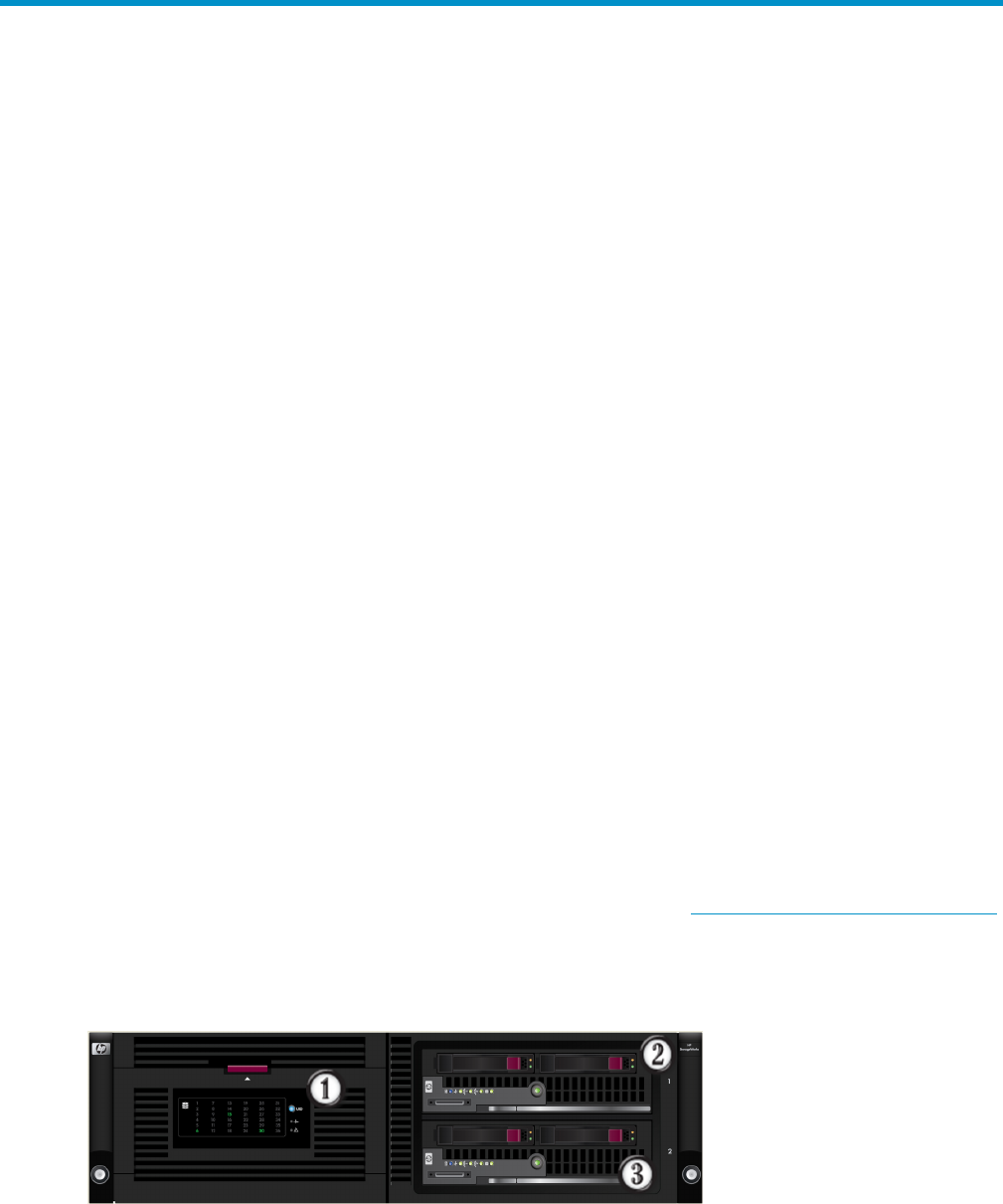
Figure 1 HP E5000 Messaging System – all models
1. Disk drive drawer
2. Server blade 1, Bay 1
3. Server blade 2, Bay 2
7
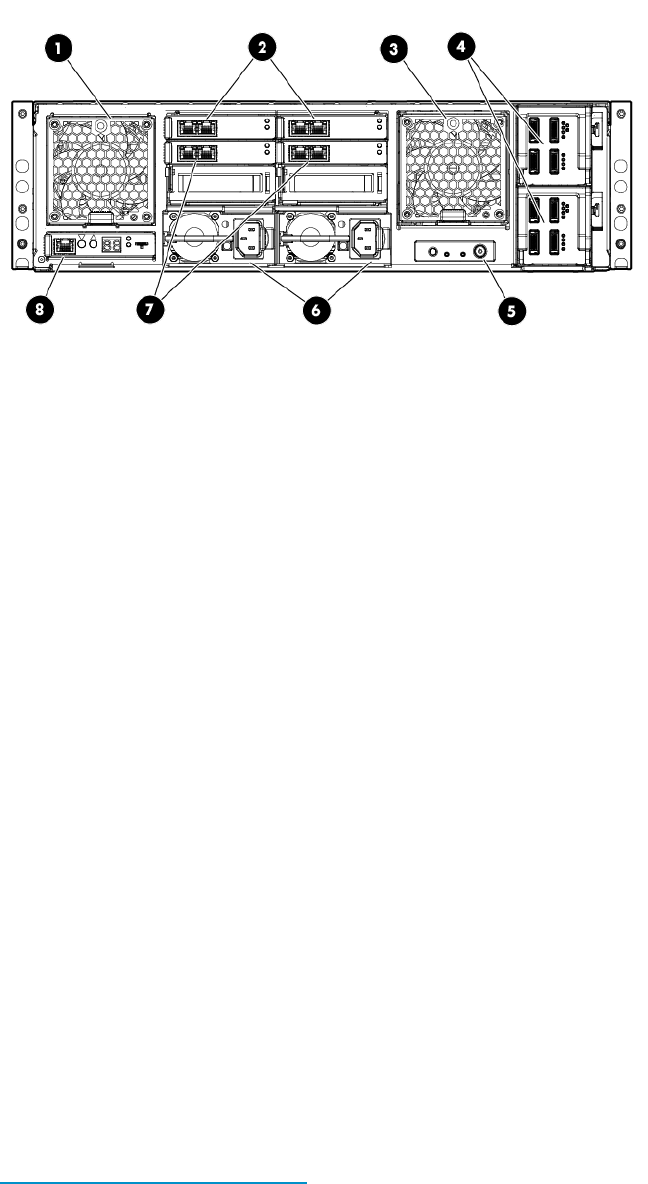
Figure 2 HP E5000 Messaging System rear view
1. System fan
2. HP StorageWorks 2-port Ethernet I/O module (2) (These modules connect to the NIC located on the server blade
motherboard)
3. Drive fan
4. SAS I/O module (2)
5. Power button
6. Power supply (2)
7. HP StorageWorks 2-port Ethernet I/O module (These modules (2) connect to the NIC located on top of the Mezzanine
card on the server blade. Standard on the E5500 and E5700 and can be added as option for the E5300
8. Management port (for iLO and Enclosure Manager Unit)
Messaging system software components
The E5000 Messaging System includes factory integration of the hardware and pre-loading of the
E5000 software image, including Windows Server 2008 R2, which has been pre-installed and
activated. The E5000 system configuration also includes the HP E5000 Configuration Wizard and
E5000 Messaging System Exchange Deployment Tool, which are used to deploy the Exchange
servers and storage in their optimal configurations.
The E5000 Configuration Wizard assists during the initial out of box setup and configuration of
the messaging system. This tool helps to configure each of the customer specific settings needed
to prepare the server.
Exchange 2010 is then installed and configured using the E5000 Messaging System Exchange
Deployment Tool, which has been developed to automate many of the deployment tasks.
To provide ongoing monitoring and facilitate management, the messaging system includes the
E5000 System Manager, which provides a snapshot view of the health and status of the messaging
system as well as tools to manage firmware updates.
For a more complete description of E5000 Messaging System features, see
nl
http://www.hp.com/go/E5000.
8 HP E5000 Messaging Systems for Microsoft Exchange

2 Preparing to install the messaging system
Before you install the messaging system, plan how you will integrate the system into your network
and whether you will use Insight Remote Support (see “HP Insight Remote Support software” (page
60)).
Exchange Server 2010 network requirements
Exchange Server 2010 includes a high-availability feature called Database Availability Group
(DAG), which requires two networks:
•Client/MAPI network provides the following functions:
Server-to-server connectivity between the Client Access Servers (CAS), Hub Transport,
and Mailbox server roles
◦
◦Server-to-server communication with domain controllers, global catalog servers, and name
services like DNS.
◦Management of Exchange client traffic such as Outlook and Outlook Web App
◦Exchange client access to mail on Client Access Servers.
◦Replication, if the replication network is unavailable.
•Replication network provides the cluster heartbeat, Exchange Server 2010 log shipping, and
database seeding or reseeding when available.
IMPORTANT: The Replication and MAPI networks should be isolated from each other, preventing
Client/MAPI and Replication network traffic from being routed between networks.
E5000 EMU network connections
To facilitate manageability and diagnostic services on the messaging system, the server blades
require network connections to the EMU. The EMU provides connections to two management
processors:
•EMU processor
•iLO processor for each server blade
EMU iLO should be connected to the Client/Mapi network or to the dedicated management network
if used. Because many administrators use iLO remote management functions, including virtual
console, HP recommends that you configure the EMU so that administrators have remote network
access to the unit. The EMU and iLO management processors support DHCP and static network
addressing. To simplify initial setup, the processors are configured for static addressing as follows:
•EMU: 10.0.0.10
•Server 1 iLO: 10.0.0.11
•Server 2 iLO: 10.0.0.12
•Subnet: 255.255.255.0
Figure 3 (page 10) shows the network ports on the rear of the messaging system enclosure.
Exchange Server 2010 network requirements 9
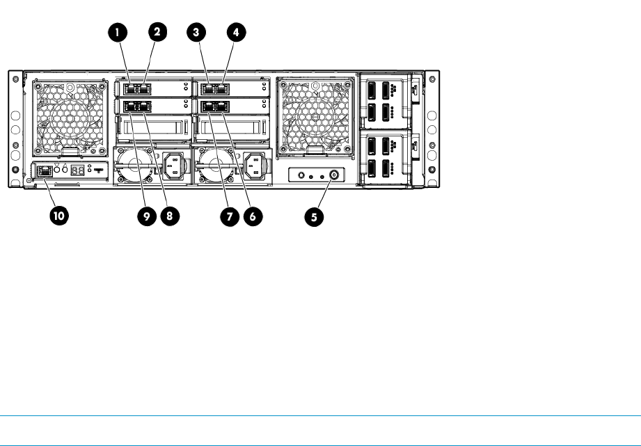
Figure 3 Network ports
6. Server 2, Mezz NIC, port 21. Server 1, NIC, port 1
7. Server 1, Mezz NIC, port 22. Server 2, NIC port 1
8. Server 2, Mezz NIC, port 13. Server 1, NIC port 2
9. Server 1, Mezz NIC, port 14. Server 2, NIC port 2
10. Enclosure Manager NIC. Includes ilO connections for both
servers.
5. E5000 enclosure power button
NOTE: E5300 models do not come standard with Mezz NICs on the servers.
Planning the E5300 Messaging System network configuration
This section describes the recommended E5300 network configuration and EMU connection options.
Typical E5300 Messaging System network configuration
Figure 4 (page 11) shows the recommended E5300 Messaging System network configuration
expected by the E5000 Configuration Wizard described in “Configuring the messaging system
software” (page 24).
10 Preparing to install the messaging system
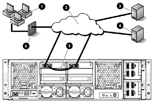
Figure 4 Recommended E5300 Messaging System network configuration
4. Domain controller1. Clients
5. Replication network2. Client/MAPI network
6. Firewall3. File share witness
By default, the E5000 Configuration Wizard sets up the Client/MAPI and Replication networks
as follows:
•Client/MAPI network
Server 1/Port 1 and Server 2/Port 2 network ports connect to this network.◦
◦Labels this network as the MAPI network on each server.
◦The default setting is static, but you can use the E5000 Configuration Wizard to configure
DHCP addressing.
•Replication network
Server 1/Port 2 and Server 2/Port 1 network ports connect to the replication network.◦
◦The E5000 Configuration Wizard automatically sets these static addresses by default
(but also allows you to change them):
–Server 1 – 10.0.0.1
–Server 2 – 10.0.0.2
Use one of the Ethernet cables shipped with the E5000 system to connect the replication ports,
as shown in Figure 4 (page 11).
E5300 Messaging System connection options
Figure 5 (page 12) shows the recommended option for connecting the EMU to the servers (this
configuration is recommended after the initial configuration. For the initial configuration of EMU
and iLO, the EMU port must be connected directly to the administrator's laptop or PC).
Figure 5 (page 12) shows the recommended Replication network configuration option. To use this
option, you need a VLAN switch, and you must ensure that the MAPI and Replication networks
are kept separate.
Planning the E5300 Messaging System network configuration 11
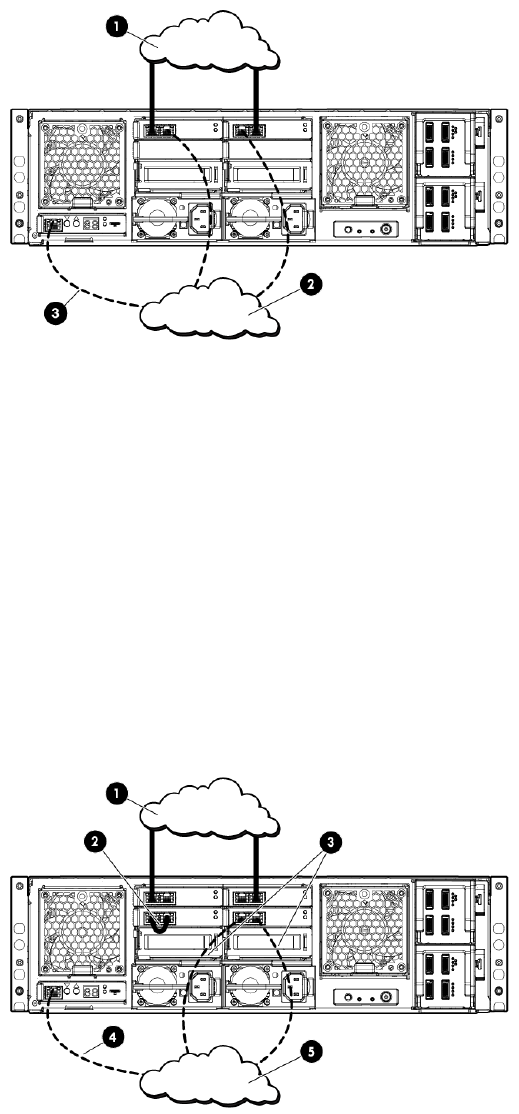
Figure 5 E5300 Messaging System connection options
1. Client/MAPI network
2. Replication network
3. Connection to EMU
Planning the E5500/E5700 Messaging System network configuration
This section describes the typical E5500/E5700 network configuration and EMU connection
options.
Typical E5500/E5700 Messaging System network configuration
Figure 6 (page 12) shows the typical E5500/5700 network configuration expected by the E5000
Configuration Wizard, as described in “Configuring the messaging system software” (page 24).
Figure 6 Management network (recommended)
4. Connection to EMU1. Client/MAPI network
5. Management network2. Replication network
3. Connections to management network
By default, the E5000 Configuration Wizard sets up the Client/MAPI and Replication networks
as follows:
•Client/MAPI network
12 Preparing to install the messaging system
Server1/Port 1 and Server2/Port 2 network ports connect to this network.◦
◦The network is labeled as the MAPI network on each server.
•Replication network
Server 1-Mezz NIC/Port 1 and Server 2-Mezz NIC/Port 1 network ports connect to this
network.
◦
◦The E5000 Configuration Wizard automatically assigns these static addresses:
Server 1 – 10.0.0.1–
–Server 2 – 10.0.0.2
Use one of the Ethernet cables shipped with the messaging system to connect the replication
ports, as shown in Figure 4 (page 11).
E5500/E5700 Messaging System EMU connection options
The E5500 and E5700 enclosures have more NIC ports than the 5300 Messaging System enclosure,
and provide more network connection options. Figure 6 (page 12) shows the recommended
management network configuration. The Mezz B ports may be used to connect to the EMU, and
while this is the intention, this method of connection is not required.
While alternate network ports can be used for network-based backup or teamed with the MAPI
network, they can also be used for EMU connectivity. As with the E5300 Messaging System system,
the Client/MAPI or Replication network can also be used to establish EM network connectivity to
the servers.
Planning the E5500/E5700 Messaging System network configuration 13

3 Installing the messaging system
This chapter explains how to install the messaging system hardware.
Check the kit contents
Remove the contents, making sure you have all the components listed below. If components are
missing, contact HP technical support.
Hardware
•HP E5000 Messaging System base system configuration
•Expansion nodes if deploying an E5700 configuration or if purchased as an upgrade option
for other configurations
•Power cords
•1.2m CAT5 Ethernet cable
•0.5m mini SAS cable and 2m mini SAS cable per expansion node
Media and documentation
•Safety and Disposal Documentation CD
•HP E5000 System Recovery DVD
•End User License Agreement
•Certificate of Authenticity Card
•Storage System Rail Kit
•HP ProLiant Essentials Integrated Lights-Out Advanced Pack
Locate and record the product number, serial number, and SAID number
Before you begin installation, locate and write down the product number of the storage system,
serial number, and support contract service agreement ID (SAID) number.
The product number of the storage system and serial number are located in three places:
•Top of the storage system
•Back of the storage system
•On the storage system shipping box
The SAID number is listed on your service contract agreement (see “Obtaining the Service Agreement
ID (SAID)” (page 61)).
14 Installing the messaging system
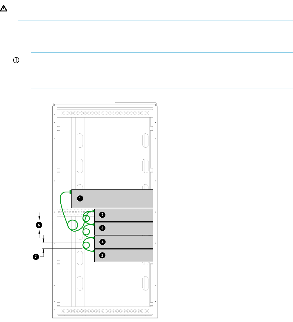
Unpack and rack the messaging system hardware
WARNING! The messaging system enclosure is heavy. Always use at least two people to move
the storage system into the rack.
1. If you ordered the messaging system without the rack, install the rail kit and enclosure by
following the HP Rail Kit Installation Instructions that are included with the rail kit.
If your messaging system is delivered in a rack, proceed to Step 2.
IMPORTANT: Ensure that cabling in the back of the rack system does not interfere with
system operation or maintenance. Bind cables loosely with cable ties and route the excess
out of the way, along the side of the rack, to keep system components and indicators visible
and accessible.
1. Messaging system enclosure
2–5. Expansion nodes (optional)
6, 7. Cable connection, with no bend radius smaller than 5 cm
Unpack and rack the messaging system hardware 15
2. If you purchased an expansion node, rack and cable the expansion node(s) before moving
to the next step.
a. Add expansion nodes to the rack by following the HP StorageWorks 2U Storage System
Rail Kit Installation Instructions, packaged with the rail kit.
b. Cable the expansion nodes to the messaging system chassis. For recommended cabling,
see “Install E5000 expansion nodes” (page 16).
3. Cable the messaging system to your network and attach the power cords. See “HP E5000
Messaging System rear view” (page 8) for connecting ports. For information on network
configurations, see “Preparing to install the messaging system” (page 9).
Install E5000 expansion nodes
IMPORTANT: If you order optional expansion nodes, be sure to rack and cable them to the
messaging system before powering on for initial configuration.
Install the hardware and cabling
To install the hardware and cabling:
1. Cable the additional expansion nodes to your messaging system.
2. Rack the expansion nodes.
For instructions, see the HP Rail Kit Installation Instructions.
3. Cable the additional expansion nodes to your messaging system.
IMPORTANT: Ensure that cabling in the back of the rack system does not interfere with system
operation or maintenance. Bind cables loosely with cable ties and route the excess out of the way,
along the side of the rack, to keep system components and indicators easily visible and accessible.
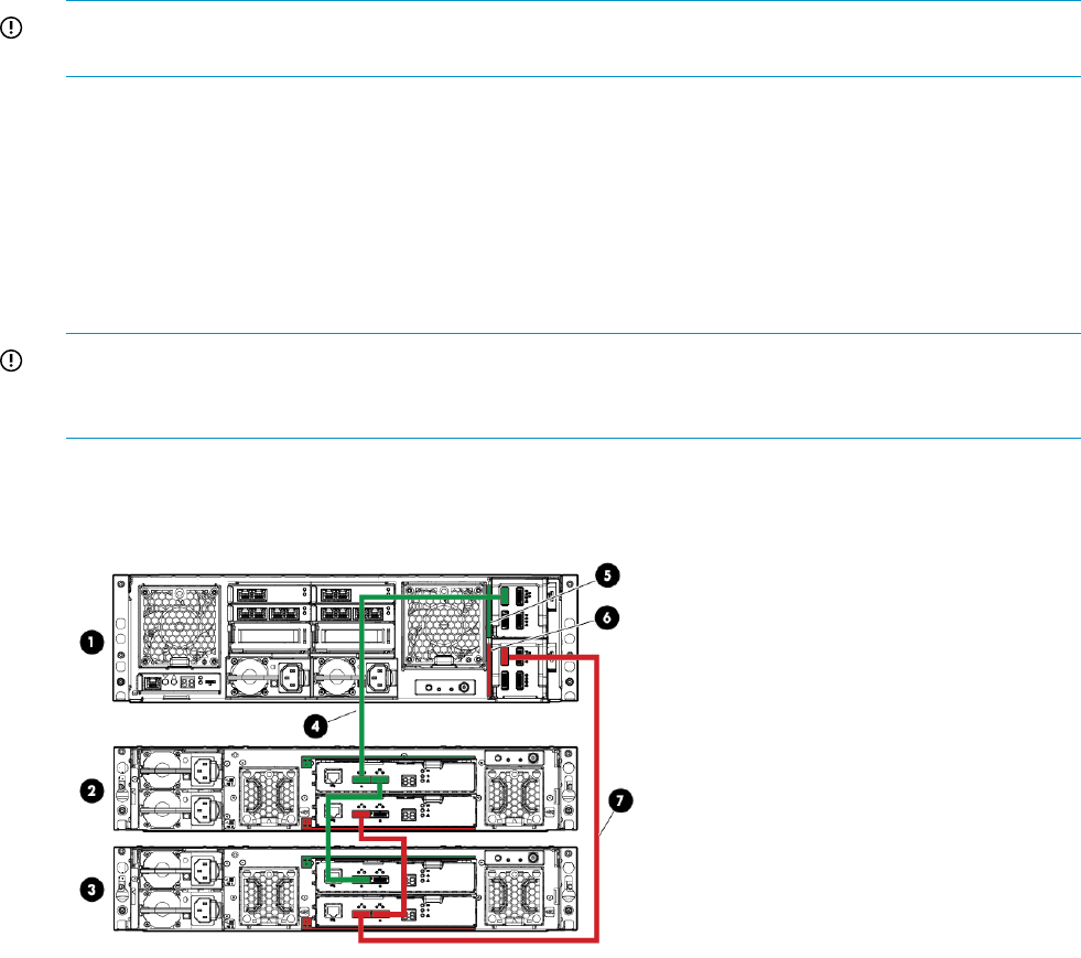
Figure 7 (page 16) shows an E5700 base configuration with two expansion nodes.
Figure 7 E5700 base configuration with 2 expansion nodes
1. Messaging system
2, 3. Expansion nodes
4. SAS cable connecting expansion node 1 (green cable)
5. Green color code for upper SAS I/O module
6. Red color code for lower SAS I/O module
7. SAS cable connecting expansion node 2 (red cable)
16 Installing the messaging system
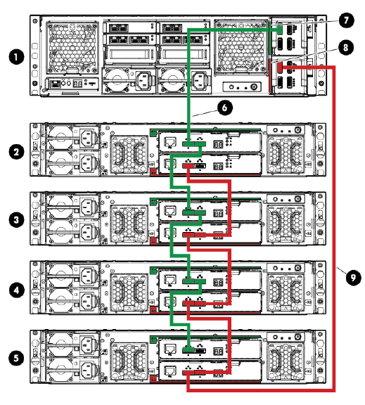
Figure 8 (page 17) shows an E5700 maximum configuration with 4 expansion nodes.
Figure 8 E5700 maximum configuration with 4 expansion nodes
1. Messaging System
2–5. Expansion nodes
6. SAS cable connecting expansion node 1 (green cable)
7. Green color code for upper SAS I/O module
8. Red color code for lower SAS I/O module
9. SAS cable connecting expansion node 2 (red cable)
Power on the messaging system
1. Power on any expansion nodes.
2. Power on the messaging system by pushing the power button on the back of the chassis.
Once the messaging system power is on, power on the server blades if they do not
automatically power on.
Configure the EMU and iLO management processors
Before configuring the management processors, verify the following:
•You have determined whether the network ports on the server are to use DHCP or static
addresses. If the network ports are to use static addresses, you must provide the addresses.
•The server NIC ports are cabled to the appropriate switches/VLANs (see“Planning the E5300
Messaging System network configuration” (page 10)).
•The expansion nodes (if present) are powered up and cabled to the messaging system
enclosure, and the messaging system enclosure system is powered up.
•For this step, the EMU port should not be connected to a switch. You can connect the EMU
port to a switch once the EMU is configured.
Power on the messaging system 17

Configure the EMU and iLO management processors as follows on both servers.
1. Establish physical connectivity to the EMU port.
1. Connect the EMU NIC port directly to a local system or laptop. You can use either a
crossover or a straight through Ethernet cable.
2. Configure the TCP/IP properties:
1. Open Control Panel.
•For computers running Windows Visa or Windows 7, select Network and
Sharing Center.
•For computers running Windows XP, select Network Connections.
2. Select Local Area Connection, and then select Properties.
3. For Windows Vista or Windows 7, select Internet Protocol Version 4 (TCP/IPv4),
and then select Properties.
For Windows XP, select Internet Protocol (TCP/IP), and then select Properties.
4. If Use the following IP address: is selected, record values for the following items and
restore them after completing the EMU and iLO setup:
•IP address
•Subnet mask
•Default gateway
5. Enter the following values:
•IP address: 10.0.0.20
•Subnet mask: 255.255.255.0
3. The EMU and iLO interfaces have been assigned IP addresses during factory setup. You
must either update the factory values with site-specific static IP addresses or, to obtain IP
address automatically, select Obtain an IP address automatically in the TPC/IP Properties
dialog. Before continuing, ping the following IP addresses to test connectivity to the EMU
and the iLO located in each of the servers: 10.0.0.10, 10.0.0.11, and 10.0.0.12.
2. Configure each iLO.
1. Point Internet Explorer at the iLO IP address:
2. Enter the administrator password found on the pull tab on the front of the server blade.
HP recommends that you change the administrator password. Launch Internet Explorer
and enter the URL of the first iLO address: https://10.0.0.11. You will be prompted
to enter the user name and password. The password for the Administrator account is
located on the pull-out tab on the front of the server blade. After you have successfully
18 Installing the messaging system
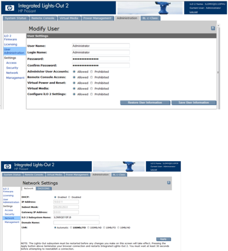
logged into the iLO, you can change the Administrator password and select the
Administration tab under the User Administration section.
3. Under the Administration tab, configure the network as required for your environment.
Select the section labeled Network. You can either enable DHCP or edit the IP address
details and enter site-specific network settings. The following example shows a DHCP
configuration.
4. After completing your changes, click Apply to save your settings.
5. Repeat the process on the other server blade. Launch Internet Explorer and entering the
following URL: https://10.0.0.12.
3. Configure the EMU.
Configure the EMU and iLO management processors 19
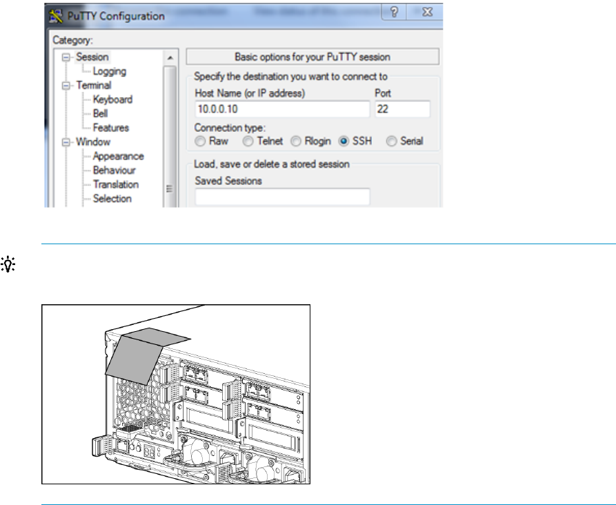
1. Connect to the Enclosure Manager software using an ssh compatible tool like PuTTY. In
the PuTTY session basic options, enter the IP address of the EMU (10.0.0.10), port 22,
and connection type SSH.
TIP: The password is printed on a tear away label attached to the top rear of the
enclosure.
20 Installing the messaging system

2. After you have connected to the EMU, set the following attributes:
•EMU (DNS) name
•rack name
•EMU password
•IP addressing method.
Example 1 Setting attributes
E5000-1-EM> set em name E5000-1-EM
IDP Enclosure Manager name changed to E5000-1-EM.
E5000-1-EM> set rack name CustomerRackName
Changed rack name to "CustomerRackName".
E5000-1-EM> set password
New Password: ********
Confirm : ********
Changed password for the "Administrator" user account.
E5000-1-EM> set ipconfig dhcp
DHCP successfully enabled.
This setting change will take effect immediately.
E5000-1-EM>
NOTE: See “EMU reference” (page 153) for information on using CLI commands.
4. Complete the configuration.
1. Now that both server iLO and the EMU have been properly configured for the network
environment, connect the EMU to the appropriate switch/VLAN/subnet.
2. Log in to the EMU using ssh and the newly assigned EMU name and validate connectivity.
Example 2 Verifying connectivity
E5000-1-EM> show server list all show server list all
Bay iLO Name iLO IP Address Status Power UID
--- ----------------------------- --------------- -------- ------- ---
1 ILOMXQ0110FJ9 16.78.90.51 OK On Off
2 ILOMXQ0110FHU 16.78.90.113 OK Off Off
Totals: 2 server blades installed, 1 powered on.
Accessing the messaging system
For initial configuration of the messaging system, you must have console access for each of the
server blades. You can use either a local I/O diagnostic (SUV) cable or an iLO connection. The
iLO connection is the preferred method because it allows for remote access.
For remote access, open an Internet Explorer window and enter the iLO name or IP address for
the server blade located in Bay1. For more information about IP addressing and subnets, see
“E5000 EMU network connections” (page 9). You log in using the iLO Administrator name and
newly created password for that blade.
For instructions on using iLO, see the Integrated Lights Out user guide available from
nl
Accessing the messaging system 21
http://www.hp.com/go/ilo. On the iLO web page, select iLO Firmware (under iLO Support &
Downloads, on the right), then select Manuals (from menu on the left).
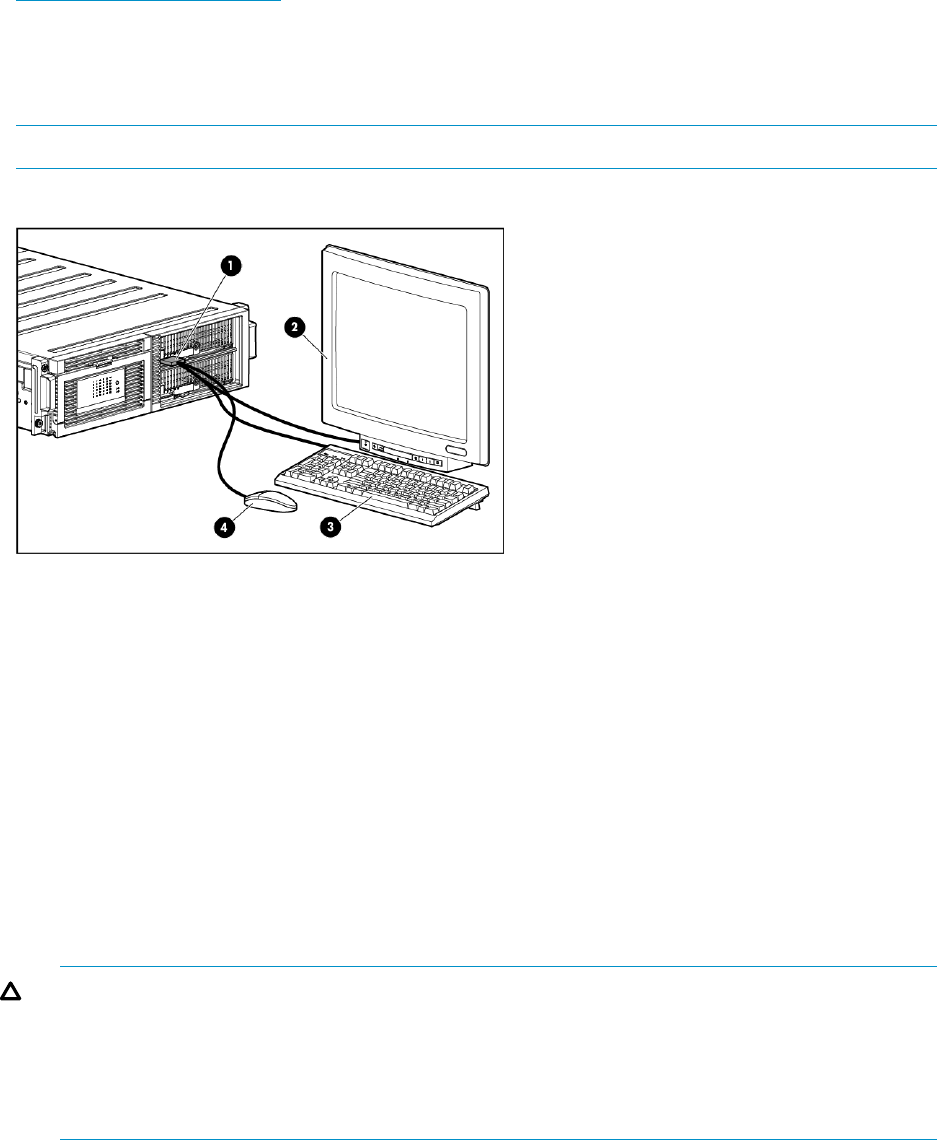
If you are using the direct connect method, connect the supplied SUV cable to the front of the
messaging system server blades in the following sequence: keyboard, mouse, monitor cable, and
monitor power cable.
NOTE: The keyboard, mouse, and monitor are not provided with the messaging system.
Figure 9 Keyboard, mouse, and monitor
1. Messaging system enclosure
2. Monitor
3. Keyboard
4. Mouse
Adding expansion nodes to an installed messaging system
To add expansion nodes to the messaging system:
1. Use the Exchange Management Console or the Exchange Management Shell to failover the
databases from the bay 1 server to the bay 2 server.
2. Power on the expansion node.
3. Reboot the bay 1 server and run the E5000 Configuration Wizard on the bay 1 server from
the All Programs shortcut.
CAUTION: In some cases, when adding new expansion nodes, disks are seen through a
single path. This condition is reported as an error in the diagnostics initially performed by HP
E5000 Configuration Wizard. To fix this problem, power cycle the expansion nodes by
pressing and holding the button on the back of the unit, then pressing and holding the button
once again to power them back on. Then re-run the HP E5000 Configuration Wizard from
the All Programs shortcut.
For instructions, see (page 24).
The messaging system identifies the new storage and creates new LUNs.
4. Exit the Initial Configuration Wizard at the first opportunity.
5. On the bay 2 server, use the Exchange Management Console or the Exchange Management
Shell to manually failover the databases from the bay 2 server to the bay 1 server.
6. Reboot the bay 2 server and manually run the E5000 Configuration Wizard on the bay 2
server.
22 Installing the messaging system
7. Rebalance the databases using the RedistributeActiveDatabases.ps1 script located
(by default) at \Program Files\Microsoft\Exchange Server\V14\scripts. Run
this script within the Exchange Management Console.
8. Within the Microsoft Exchange Management Console, select New Mailbox Database.
a. Name the new database the next item in the sequence (for example, DB10).
b. Select a server.
c. Set the path based on the newly created LUNs.
9. Use Microsoft Exchange Management Console to add a mailbox copy.
Adding hard drives to an installed E5300 system
If you ordered an E5300 system with fewer than the maximum number of hard drives, you can
add drives as follows:
1. Power off the system as described in (page 63).
2. Install the new drives as described in (page 125)
3. Power on the system.
4. Run the E5000 Configuration Wizard on the first server manually from the All Programs
shortcut. The wizard recognizes the new storage and creates new LUNs. Exit the wizard at
the first opportunity.
5. Run the wizard on the second server.
6. Using Microsoft Exchange Management Console, select New mailbox database and name
the new the next item in the sequence. For example, if the previous is DB9, name the new one
DB10.
7. Choose a server and set the path based on the new LUNs.
8. Use Microsoft Exchange Management Console to add a mailbox copy on the other server.
Adding hard drives to an installed E5300 system 23
4 Configuring the messaging system software
This chapter explains how to configure system software using the HP E5000 Configuration Wizard
and how to deploy Microsoft Exchange Server 2010 using the HP E5000 Messaging System
Exchange Deployment Tool.
IMPORTANT: To configure the E5000 messaging system, you must run these tools on each server
blade.
HP recommends that you fully complete the Configuration Wizard and Exchange Deployment Tool
on the Bay 1 server blade before beginning to configure the Bay 2 server blade.
After you have completed the initial configuration, be sure to install any available software updates
as described in “ Updating the messaging system software” (page 63).
Configuring server software
The HP E5000 solution should be powered up and the network ports cabled for your network
configuration, including the EMU port. For configurations that use expansion nodes, such as the
E57000, all storage enclosures should be cabled to the messaging system and powered on.
Complete the following steps, first on server 1, and then on server 2. Do not start on the second
server until you have completed the steps on server 1. When the server is powered up for the first
time, it completes the initial Windows configuration process and then launches the E5000 Messaging
System Configuration Wizard
1. Enter your locale information in the Windows setup dialog and accept the license terms. The
Windows setup completes in approximately 15 minutes and the E5000 Configuration Wizard
starts.
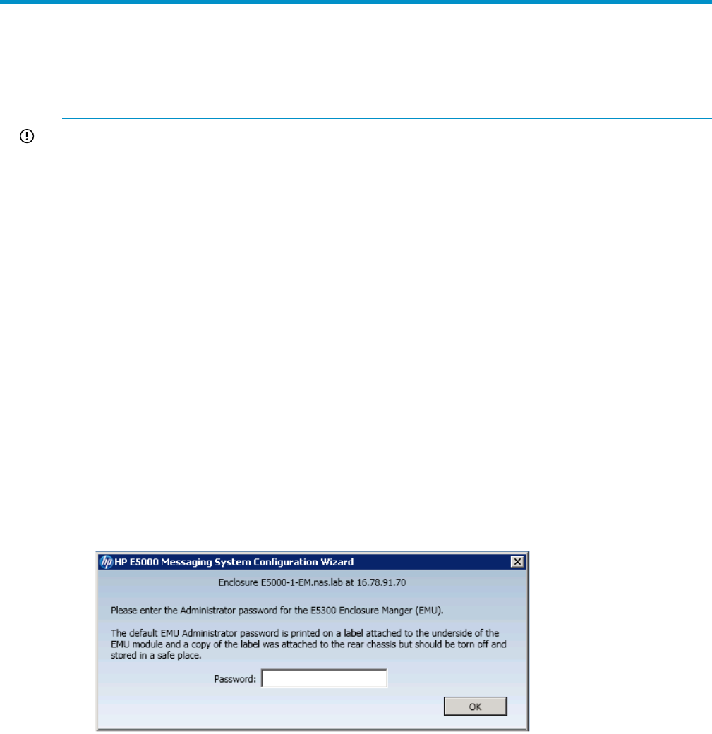
2. Enter the EMU Administrator password as instructed in the E5000 Configuration Wizard
window:
The wizard automatically runs a diagnostics program to ensure that the HP E5000 solution is
correctly configured. An error message appears if there is a configuration error. When the
configuration is correct, the E5000 Configuration Wizard resumes.
3. When the Welcome screen appears, HP recommends that you select the default action, Yes,
I would like to use this wizard for easy system configuration and Microsoft Exchange 2010
setup.
24 Configuring the messaging system software
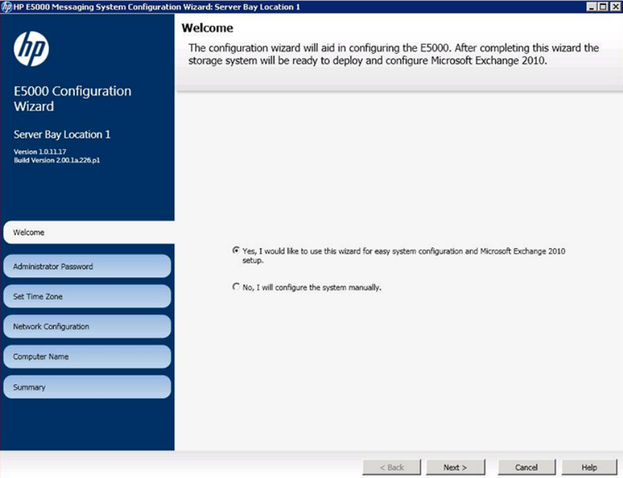
Click Next.
4. Set the time zone and then click Next. The correct local time zone is set when the server joins
a domain.
Configuring server software 25
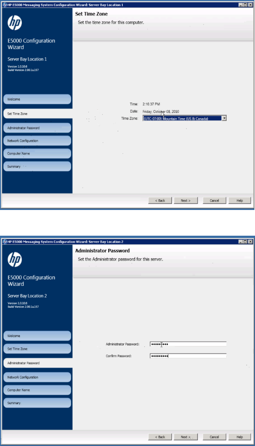
5. Set the Administrator password and then click Next.
26 Configuring the messaging system software
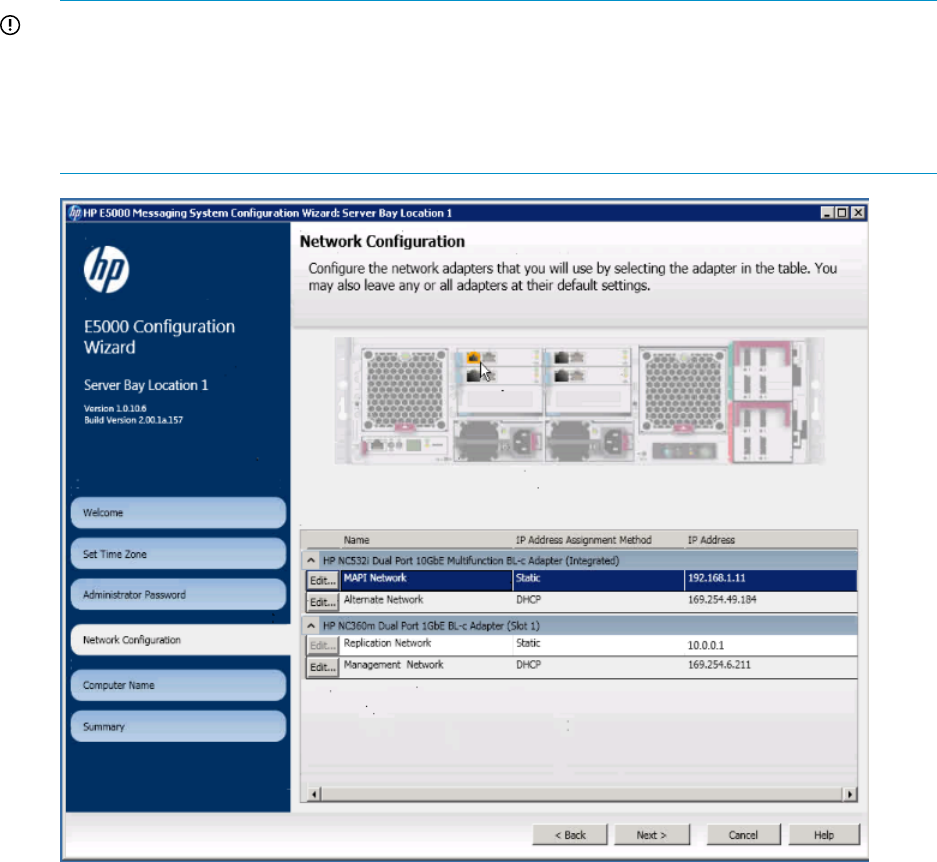
6. Set the network configuration. Review each network port configurations and either accept the
default values or press Edit to change them. Click Next when finished.
IMPORTANT: By default, the Replication network is set to a static network 10.0.0.0/30 with
IP 10.0.0.1 on the first node and 10.0.0.2 on the second. If these addresses conflict with
addresses on your network, please reconfigure them to some other unused static network. The
following figure shows an E5300 configuration, which has 2 networks: Client/Mapi and
Replication. E5500/5700 configurations have 4 networks: Client/Mapi, Replication,
Management, and Alternate (see Figure 6 (page 12)).
Configuring server software 27
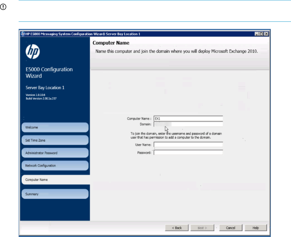
7. Set the computer name and join a domain. Enter the computer name and the name of the
domain that the computer will join. Enter the name and password of a user who has permission
to add the computer to the domain. Click Next when finished.
IMPORTANT: Be sure to record the name of the first server. You need that name when you
configure the second server.
28 Configuring the messaging system software

8. Review the summary report and complete the configuration. The Summary screen lists the
configuration settings you have made.
9. Click Configure to apply the configuration settings or Back to modify them.
When you are ready to accept the settings, click Finish to reboot the server. If you do not want
to reboot at this time, clear the box Reboot after exiting the wizard.
NOTE: The server blades contain redundant storage controllers. When a server reboots,
one of the controllers shuts down. The partner server sees this event as a redundancy loss and
creates a log entry: “drive array controllers are no longer redundant”. You can ignore the
message if it coincides with a reboot you initiated.
Continue with the next procedure, “Deploying Microsoft Exchange Server 2010” (page 30), and
complete the setup on the Bay 1 server before setting up the Bay 2 server.
Configuring server software 29

Deploying Microsoft Exchange Server 2010
Follow this procedure to deploy Microsoft Exchange Server 2010. Complete the deployment of
Microsoft Exchange Server 2010 on the bay 1 server blade before beginning the configuration
of the bay 2 server blade.
IMPORTANT: Before proceeding, ensure that Active Directory has been prepared in accordance
with http://go.microsoft.com/?linkid=9738614. You must also provide a witness server to be
used by the DAG. For details on selecting and configuring a server to be a witness server, see
http://technet.microsoft.com/en-us/library/dd351107.aspx .
1. Log in to the bay 1 server. If you have completed this procedure for the bay 1 server, log in
to the bay 2 server now.
When you log in, the Windows Security screen appears. Log in using the domain administrator
credentials you used to join the server to the domain. The Exchange Deployment Tool launches
automatically and displays the Introduction screen.
HP recommends that you run the tests in the Prerequisites section. For detailed information on
Microsoft prerequisites, visit the links on the page.
After you have run the tests, click Next.
NOTE: You need a properly configured browser, including proxy configuration (if applicable),
to access the links.
2. The End User License Agreement Confirmation screen appears. After reading and accepting
the agreements, click Next.
3. The Exchange Tools screen appears. If you choose to run a Jetstress test, select the type of
Jetstress test. For more information about Jetstress, see (page 35).
30 Configuring the messaging system software
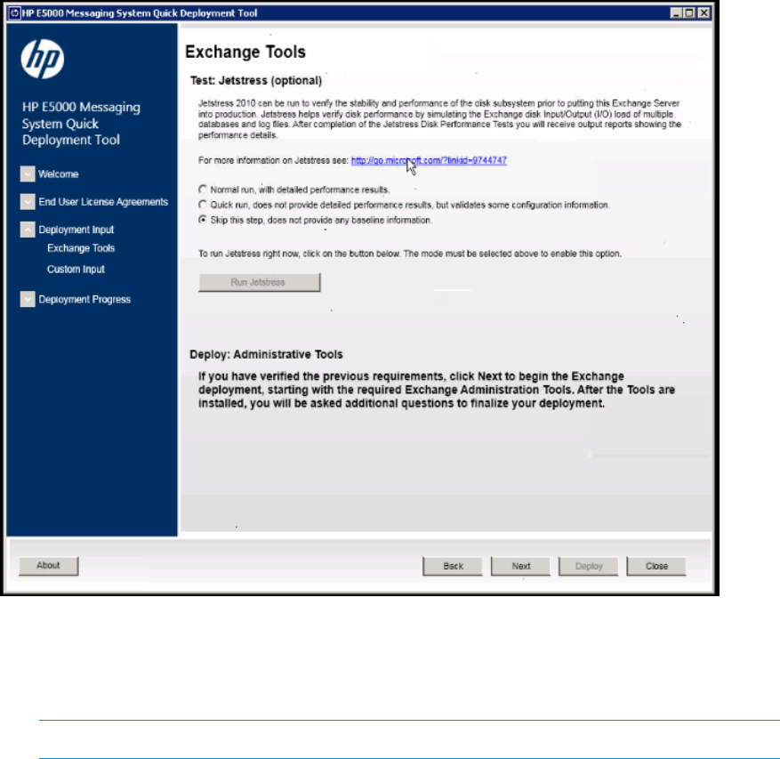
a. A normal run of the Jetstress test provides a baseline benchmark of the system. HP
recommends that you run the test now, but only if you have sufficient time before deploying
the server into production. Click Next to begin deployment of the Exchange Administration
Tools. This should take approximately five minutes.
NOTE: A normal run of the Jetstress test can take 24 hours to complete.
b. A quick run of the Jetstress test does not provide detail performance results but can be
used to validate some of the configuration information .
Choose a quick run if you cannot dedicate the time for a normal Jetstress test. If neither
option is acceptable, you may choose to skip the Jetstress test. Click Next to begin
deployment of the Exchange Administration Tools.
4. After the deployment completes, complete the Custom Input screen.
Deploying Microsoft Exchange Server 2010 31
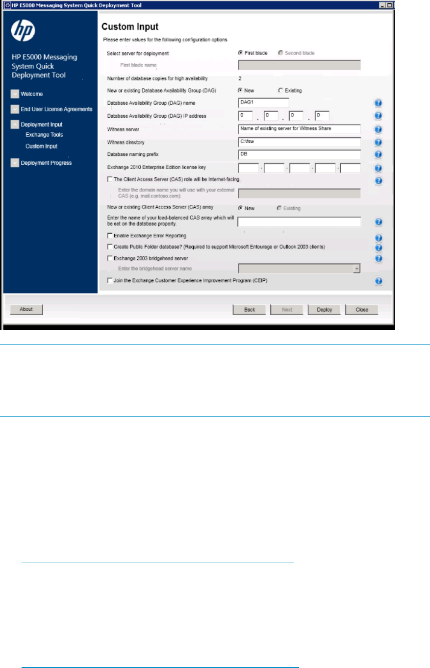
NOTE: When you reach this screen while deploying to the bay 1 server, select First blade.
The Exchange Deployment Tool automatically detects whether any are found in the existing
Exchange organization (when existing is selected). When you reach this screen while deploying
to the bay 2 server, select Second blade, and then enter the name of the bay 1 server (not the
name of the bay 2 server).
Complete each item on this screen as needed for your deployment:
•New or existing Availability Group (DAG) name. The Exchange Deployment Tool
automatically detects if any are found in the existing Exchange organization. Accept the
default name or enter a new name of one already exists.
•Availability Group IP address. Using an IP address of 0.0.0.0 configures the DAG to use
DHCP. You can update the configured IP address later using the Exchange Management
Shell, or additional addresses can be added later using the Set-AvailabilityGroup
PowerShell command.
•Witness Server name. See
nl
http://technet.microsoft.com/en-us/library/dd351107.aspx for information about special
considerations if placing the suggested default Witness Server on a domain controller:
•Witness directory. Specify the local path on the Witness Server.
•name prefix. Use the suggested default or enter a new name. The Exchange Deployment
Tool appends numbers to the name and verifies that the name is unique at the organization
level (an Exchange 2010 requirement).
•Client Access Server (CAS) is Internet facing. For more information, see
nl
http://technet.microsoft.com/en-us/library/dd351198.aspx for more information.
•New or Existing CAS array. Enter a name for New or select from the drop-down for
Existing (if detected).
32 Configuring the messaging system software

•Enter the name of your load-balanced CAS array which is set on the database property.
If no load-balanced CAS array is available, see:
◦http://go.microsoft.com/?linkid=9738617
◦http://go.microsoft.com/?linkid=9738618
•Enable Error Reporting. For more information, see
nl
http://go.microsoft.com/?linkid=9738619
•Create Public Folder database. To connect to Exchange 2010 Microsoft Entourage or
Outlook 2003, clients require a public folder database. The Exchange Deployment Tool
runs Exchange setup to create the public folder database for you. This option is available
only on the first Exchange 2010 Mailbox server being deployed. The public folders on
this system are designed primarily for Free-Busy usage and not large-scale folder replicas
or other applications.
•Exchange 2003 bridgehead server. Use the parameter to specify an Exchange 2003
bridgehead server that is located in the routing group to which you plan to create the
initial routing group connector. A routing group connector is required for mail flow
between Exchange 2010 and Exchange 2003 when these Exchange server versions
coexist in the same organization.
•Customer Experience Improvement Program. See
nl
http://go.microsoft.com/?linkid=9738620.
Click Deploy to start the tools deployment process. This process typically requires about 45
minutes to one hour.
5. The Exchange Deployment Tool displays the Deployment Status screen.
Deploying Microsoft Exchange Server 2010 33
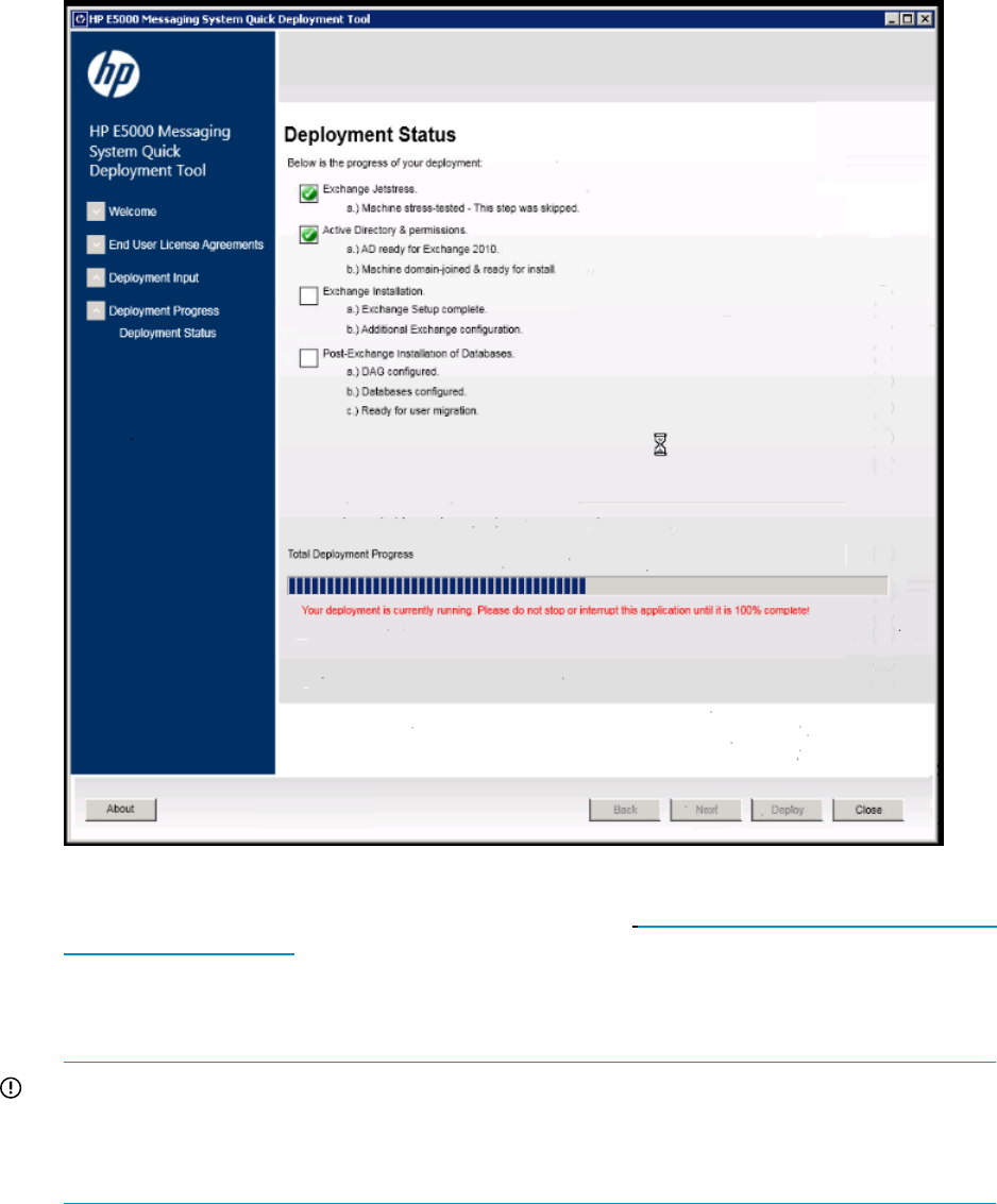
When the process completes, you are prompted to allow the server to reboot. After the reboot,
log in again with Exchange administrator credentials (see http://technet.microsoft.com/en-us/
library/ee681663.aspx) to complete the deployment (the Exchange Deployment Tool reappears
automatically when you log in).
6. After deployment completes, the Exchange Deployment Tool displays a success message and
prompts you to run the Best Practices Analyzer.
IMPORTANT: Complete the E5000 Configuration Wizard and the deployment of Microsoft
Exchange Server 2010 on the bay 2 server now before continuing on.
HP recommends that you do not run the Analyzer until the tools deployment completes on the
second server.
7. Accept the prompt to run the Analyzer. The Best Practices Analyzer screen appears.
34 Configuring the messaging system software
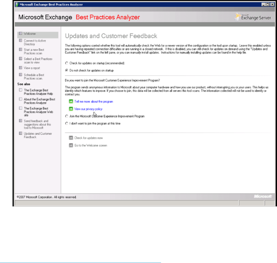
The Exchange Best Practices Analyzer is located in the Toolbox node in the Exchange Management
Console. You can use the Best Practices Analyzer to connect to Directory, start a scan, and perform
other Exchange operations.
For more information about Microsoft Exchange Server 2010 and to download the complete help
file, see Exchange Server 2010 at
nl
http://technet.microsoft.com/en-us/library/bb124558.aspx.
Next steps
The messaging system is now installed and configured in a DAG with the number of database
copies you have specified. At this time, you may choose to configure event notification. For more
information, see “Configuring Event Notifier for proactive email (SMTP) event notification” (page
39).
HP strongly recommends that you also install Insight Remote Support as described in “HP Insight
Remote Support software” (page 60).
Using Microsoft Exchange Jetstress and Load Generator
You can use Microsoft Exchange Jetstress and Load Generator (LoadGen) to generate a simulated
Exchange workload on your system and analyze the effect of that workload on the messaging
system.
Using Microsoft Exchange Jetstress and Load Generator 35

IMPORTANT: You must run these tools in a non-production environment to avoid potential loss
of data and performance degradation.
For more information about these tools, see Tools for Performance and Scalability Evaluation at
http://technet.microsoft.com/en-us/library/dd335108.aspx. If you are testing Jetstress, only the
E5000 servers are required. The servers must not have Exchange loaded when running Jetstress.
When running LoadGen, Exchange server 2010 SP1 is installed on both servers in the E5000
enclosure, and the Client Access Server, Hub Transport Server, and Mailbox Server roles are
installed. Because multiple roles are installed on both servers, and because of the participation of
each server in the Database Availability Group (DAG), you must use an external load balancing
method. Two possible methods are the following:
•Use a hardware load balancer.
•Use Exchange database configuration to balance load across the CAS servers manually.
◦MAPI Traffic: Assuming the users are evenly split between databases, use the
Set-MailboxDatabase cmdlet available from Microsoft at
nl
http://technet.microsoft.com/en-us/library/bb123971.aspx and specify the
rpcclientaccessserver parameter equal to cas1 for half the databases and cas2
for the other half.
◦OWA Traffic: OWA requires persistence, so direct all OWA traffic through the first CAS.
◦Exchange Sync (EAS): Direct all OWA traffic through the second CAS.
◦Other protocols (POP3, IMAP, and so forth): use DNS round-robin to get rudimentary
load balancing.
36 Configuring the messaging system software
5 Monitoring and troubleshooting the messaging system
The messaging system provides several monitoring and troubleshooting options. You can access
troubleshooting alerts and solutions to maintain the health of the messaging system from the
following:
•Notification alerts, which you sign up to receive during the initial configuration of the storage
solution
•HP E5000 System Manager
•System Management Homepage (SMH)
•Hardware component LEDs
•EMU CLI SHOW commands
•HP and Microsoft support websites
•HP Insight Remote Support software
•Microsoft Systems Center Operations Manager (SCOM) and Microsoft websites
•HP SIM. HP SIM 6.3 or later is required for proper messaging system/HP SIM integration.
NOTE: Integration with HP SIM is only supported using the WBEM/WMI interfaces. Do not
attempt to configure HP SIM to use the ProLiant SNMP agents, because the configuration is
untested and unsupported. The ProLiant SNMP agents are enabled on the messaging system
by default and should not be disabled as they are used for internal management functions. If
they are enabled for external client consumption, HP SIM must be configured so it does not
attempt to communicate with these agents.
If you are unable to resolve a messaging system operation issue after using the various options,
contact HP Support. You need to provide your Service Agreement ID (SAID) and your warranty
and entitlement labels. See “Obtaining the Service Agreement ID (SAID)” (page 61) and “Locating
the messaging system warranty entitlement labels” (page 62).
Using notification alerts
When you receive an alert, open the HP E5000 System Manager (described in “Using the E5000
System Manager” (page 43)) to view a high-level description of the issue. You may then choose
to open the System Management Homepage or HP SIM to obtain more detailed information.
IMPORTANT: While the notification alerts report issues as they arise, it is still important to monitor
the messaging system regularly to ensure optimal operation.
For more information on receiving notification alerts, see “Using notification alerts” (page 37).
Examples of error messages
Table 1 (page 37) lists examples of possible error messages and describes the needed action to
resolve the issue.
Table 1 Examples of possible error messages
ResolutionIssueMessage appears
Enter the correct Exchange license key.Entered an incorrect Exchange license
key
Not a valid license
Enter the correct Administrator
password.
Adding the wrong information for a
domain controller
You cannot reach the domain
controller
Using notification alerts 37

Table 1 Examples of possible error messages (continued)
ResolutionIssueMessage appears
You are prompted to enter the
Administrator password during the
initial configuration by the
Configuration Wizard. The messaging
system attempts to locate the domain
and then report the problem when it is
unable to locate the domain you
entered.
You are not allowed to progress
through the Configuration Wizard until
you add the correct witness server
information when prompted.
Adding incorrect information for the
witness server
ID does not exist
Enter the correct network or IP address.Adding invalid network information
for any port
Invalid mask or IP address conflict,
can't specify
Turn on the disks in expansion
enclosures and run the Configuration
Wizard again.
Not powering on the expansion nodes
before booting the system
Diagnostics flag if you have forgotten
to turn on any disks in expansion
enclosures that are cabled to the
messaging system enclosure.
If you have already run the diagnostics,
you must turn on the disks in expansion
enclosures and then re-rrun diagnostics.
If you have already run the complete
Configuration Wizard, you need only
run diagnostics again. When the
window appears that asks you if you
want to run the Configuration Wizard,
select “No Thanks.”
Warning: You will lose your disks and
LUNs if you do not turn on the disks
in expansion enclosures before
beginning the installation process.
Note: Diagnostics does not alert you
to turn on the disks in expansion
enclosures if you have not cabled them
to the messaging system enclosure.
Make sure the cables are connected
correctly and are not loose.
Incorrect cabling of the messaging
system
Single path to disks not correct; Path
error; Check your cabling
Note: This message appears during
diagnostics. If you see the word
“degraded” in the message, use the
SMHP to check the status of the
hardware. If cables become loose after
the initial configuration, the message
appears in the System Manager and
the SMHP, but you must open these
programs to observe the message.
Check to make sure you have entered
the correct IP address, and then check
the cable to make sure the EMU is
connected on the network.
Server blades and EMU attached on
the wrong networks
Cannot be reached
Note: If they are attached to the wrong
network, you lose all information about
the enclosure during the initial
installation. To verify the administrator
password, the Configuration Wizard
attempts to contact the EMU but is
unable to do so. You immediately
receive a message after the Microsoft
Windows OS sets up.
38 Monitoring and troubleshooting the messaging system

Table 1 Examples of possible error messages (continued)
ResolutionIssueMessage appears
Connect the cable in the back of the
enclosure. If the cable is not on, you
must use a MAPI network. For the
E5300, which does not offer replication
networking, you may use a public
network for replication and need to
configure the IP address manually.
Replication and MAPI network not
connected
Lost replication connection
Note: If you lose a network connection
and you’ve set up notification alerts,
you are automatically alerted. If you do
not have notification alerts, open the
System Manager, System Summary tab.
Reboot the server blade that has failed.
Open the System Manager, System
Summary tab to identify the server
blade that does not say “storage.”
Storage array lock upVolumes have failed; Degraded
controller
Microsoft Exchange marks the volumes
as failed, and the mail serving
processor fails over to the other server
blade.
Important: You must manually
rebalance the database server after
rebooting. Microsoft also offers a
redistribution script to assist you.
Periodically check the System Manager
Firmware tab to ensure you are running
the most current firmware.
Firmware not currentUnsupported firmware
Important: Be sure to check the
firmware status after you replace any
component on the messaging system.
Configuring Event Notifier for proactive email (SMTP) event notification
Configure Event Notifier to enable proevent notification to send email notification of system events.
To start the Event Notifier Configuration wizard and provide the required information for your
environment (SMTP, notification recipients, and SNMP):
Configuring Event Notifier for proactive email (SMTP) event notification 39
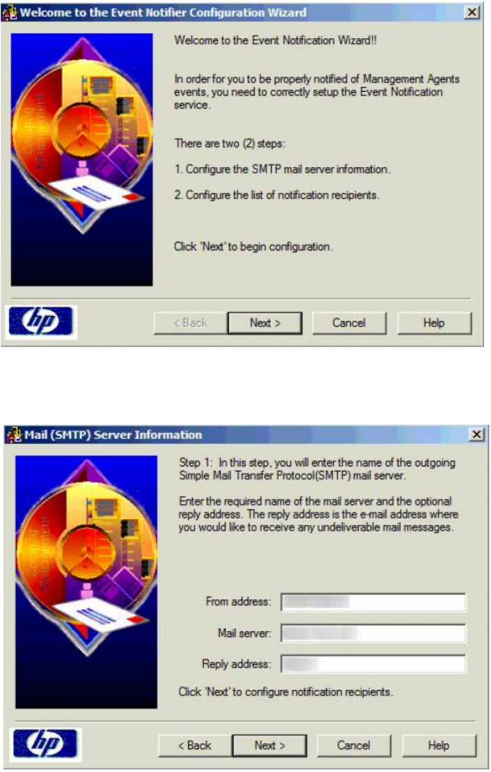
1. Click Start→All Programs→HP Management Agents→Event Notifier Config.
a. On the Welcome window, click Next.
b. Enter your address and mail server information to set up the Mail (SMTP) Server
Information, and then click Next.
c. On the Event Recipients Information screen, click Add to add a notification recipient.
40 Monitoring and troubleshooting the messaging system

d. Add a user name and address to the Notification Recipient Information dialog box, and
then click OK. Repeat this step for each user.
Click Finish after completing the notification list.
Configuring Event Notifier for proactive email (SMTP) event notification 41
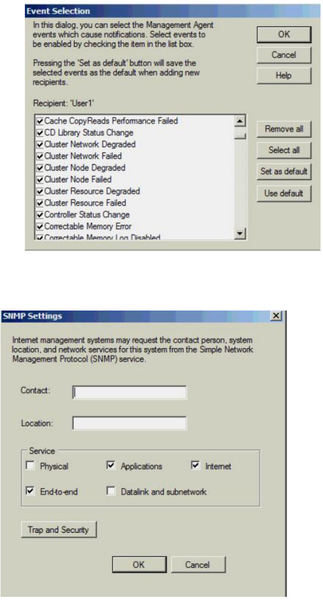
e. Select the events for which you want to be notified, and then click OK. HP recommends
that you select all events.
2. To configure the SNMP settings, provide the contact and location information for the System
Administrator, and then click OK.
42 Monitoring and troubleshooting the messaging system
3. To make SNMP visible externally:
1. Select Start→Administrative Tools→Services.
2. Select SNMP Service.
3. Right click and select Properties to display the SNMP Service properties.
4. Select the Security tab and specify the following items:
•The external hosts that may use the SNMP protocol.
•The SNMP Community string. HP recommends that you use something other than the
typical ‘Public’ string.
IMPORTANT: Configure HP SIM security to prevent the SIM management server from
gaining access to SNMP.
The SNMP trap function in the messaging system is enabled by default. Any SNMP client (on
localhost) listening on default port number 171 can receive traps. You can configure the
destination IP address using the snmp.xml configuration file in the directory \Program Files\
HPWBEM\Tools\snmp.xml.
Using the E5000 System Manager
To use the E5000 System Manager, which has been preinstalled a configured, you must Remote
Desktop into the server blade. Next, you may access the E5000 System Manager by clicking the
icon located in the tray immediately to the right of the Start button. You may also access the
E5000 System Manager by clicking Start→Administrative Tools→Server Manager. Use the System
Summary tab in the E5000 System Manager to monitor the system health status of each server
blade.
The System Summary tab shows the overall, high-level status of the messaging system hardware,
Exchange, and firmware.
To troubleshoot using the E5000 System Manager:
1. Open the HP E5000 System Manager.
2. Open the System Summary tab to review the overall health of the messaging system hardware,
Exchange, and firmware.
If the status icon is green, the system is running properly. A yellow icon is a warning that there
are conditions that might cause a problem. If the icon is red, a problem exists in the messaging
system.
3. Open each tab in the HP E5000 System Manager to assess the status of the messaging system.
4. Follow the instructions provided on the System Manager tabs for any reported issue.
NOTE: The E5000 System Manager provides the status of each server blade that is configured
in the messaging system. Be sure to note the server blade that is being assessed when you open
the E5000 System Manager. Log into each server blade to evaluate its status.
IMPORTANT: The System Manager identifies the server blade and bay location. You must run
the System Manager beginning with server blade 1, although server blade 1 might not be the
active server blade. A message appears informing you that the System Manager is evaluating
server blade 1.
Table 2 (page 44) shows the description for the messaging system status tray check mark color.
Using the E5000 System Manager 43
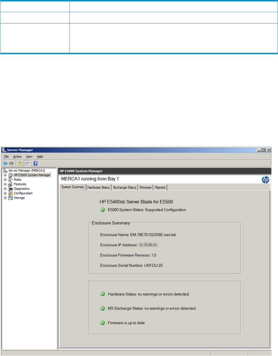
Table 2 System status tray description
DescriptionIcon check mark color
The system is running a supported configuration.Green
The system is running an unsupported configuration. The system tray icon shows a red
error symbol until Microsoft Exchange has been fully installed, or if the system is running
outside the terms of the service and support agreement (for example, the system is running
a server application other than Microsoft Exchange).
Red
System Summary
For each server blade (identified at the top of the System Manager window), the System Summary
tab of the E5000 Messaging System Manager gives information such as the enclosure name, IP
Address, firmware revision, and serial number. The lower part of the System Summary also shows
the status of hardware and Microsoft Exchange, and whether your current firmware revision is up
to date. If a green check mark does not appear beside the configuration status, go to the related
tab for information about the issue.
To review the messaging system status, open the E5000 Messaging System Manager, and then
click the System Summary tab.
Hardware Status
The Hardware Status tab in the System Manager provides the health status for each of the messaging
system components.
44 Monitoring and troubleshooting the messaging system
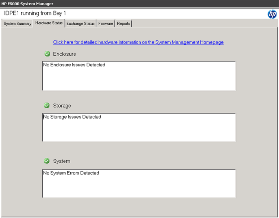
Exchange Status
The Exchange Status tab in the System Manager provides the overall Microsoft Exchange
configuration status (by default). Click any configuration item in the list at the top to see further
refined detail.
Using the E5000 System Manager 45
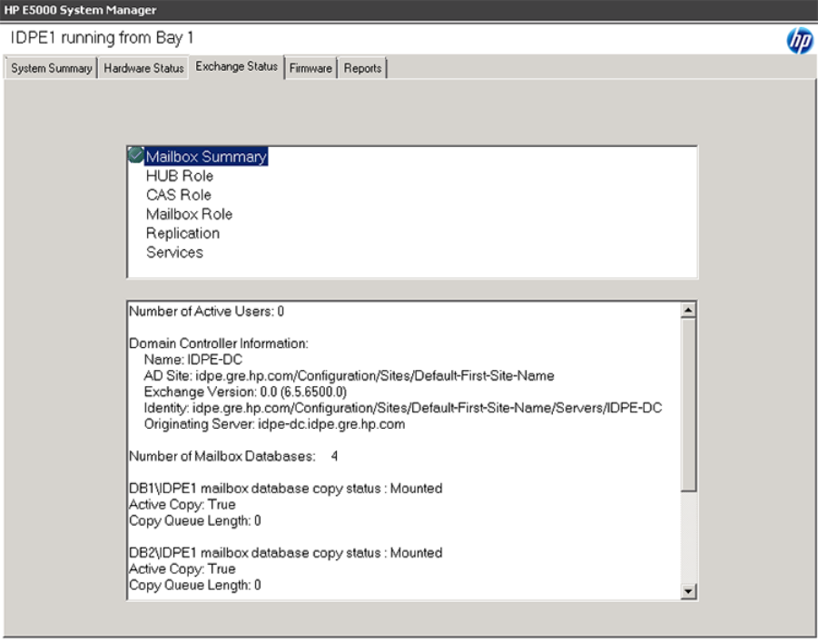
Firmware
The Firmware tab indicates whether the firmware of a component is outdated. To review the
components firmware version status, open the System Manager and click the Firmware tab. If the
specific firmware requires that you reboot after installing the update, a message instructing you to
reboot the messaging system appears. Since the tool does not connect to the Internet to identify
new firmware, you must periodically check the HP support web page and download new firmware
when available.
46 Monitoring and troubleshooting the messaging system
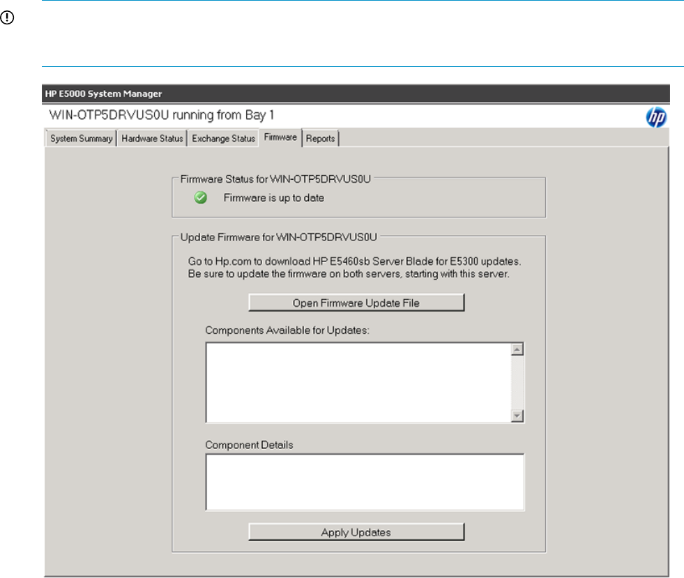
IMPORTANT: If a firmware update requires a reboot, you must reboot your messaging system
manually. For more information about firmware updates, see“Upgrading a component's firmware
version” (page 64) .
Reports
The Reports tab gathers logs for the hardware, software, Microsoft Windows system configuration,
and the Microsoft Exchange diagnostics in one place. These logs are used by HP support engineers
to help diagnose your system, if needed; you do not need to view and interpret the logs yourself.
To run the diagnostic tools, open System Manager and click the Reports tab, and then press the
Generate Support File button. After running the diagnostic tools, the Open Reports Folder button
appears. Click the Open Reports Folder button to view the diagnostic report results. The diagnostic
tools place the reports in one standard directory.
Using the E5000 System Manager 47
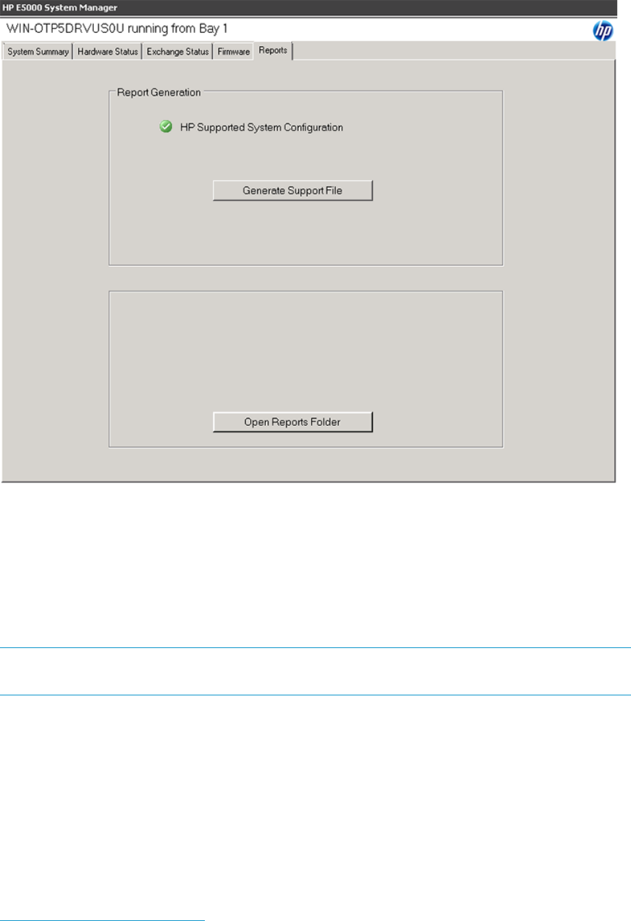
HP System Management Homepage
The HP System Management Homepage (HP SMH) is a web-based interface that consolidates and
simplifies single system management for HP servers. The SMH is the primary tool for identifying
and troubleshooting hardware issues in the messaging system. You may choose this option to drill
down to a suspected hardware problem. Go to the SMH main page and open the Overall System
Health Status and the Component Status Summary sections to review the status of the messaging
system hardware.
NOTE: The functions described in this section apply specifically to components of the messaging
system.
By aggregating the data from HP web-based agents and management utilities, HP SMH provides
a common, easy-to-use interface for displaying the following information:
•Hardware fault and status monitoring
•Performance data
•System thresholds
•Diagnostics
•Software version control for an individual server
The SMH Help menu provides documentation for using, maintaining, and troubleshooting the
application. For more information about the System Management Homepage software, go to
www.hp.com/support/manuals and enter System Management Homepage in the Search box. A
list of documents and advisories is displayed. To view SMH user guides, click the link to search
for matching products, select System Management Homepage Software, and then select Manuals.
48 Monitoring and troubleshooting the messaging system
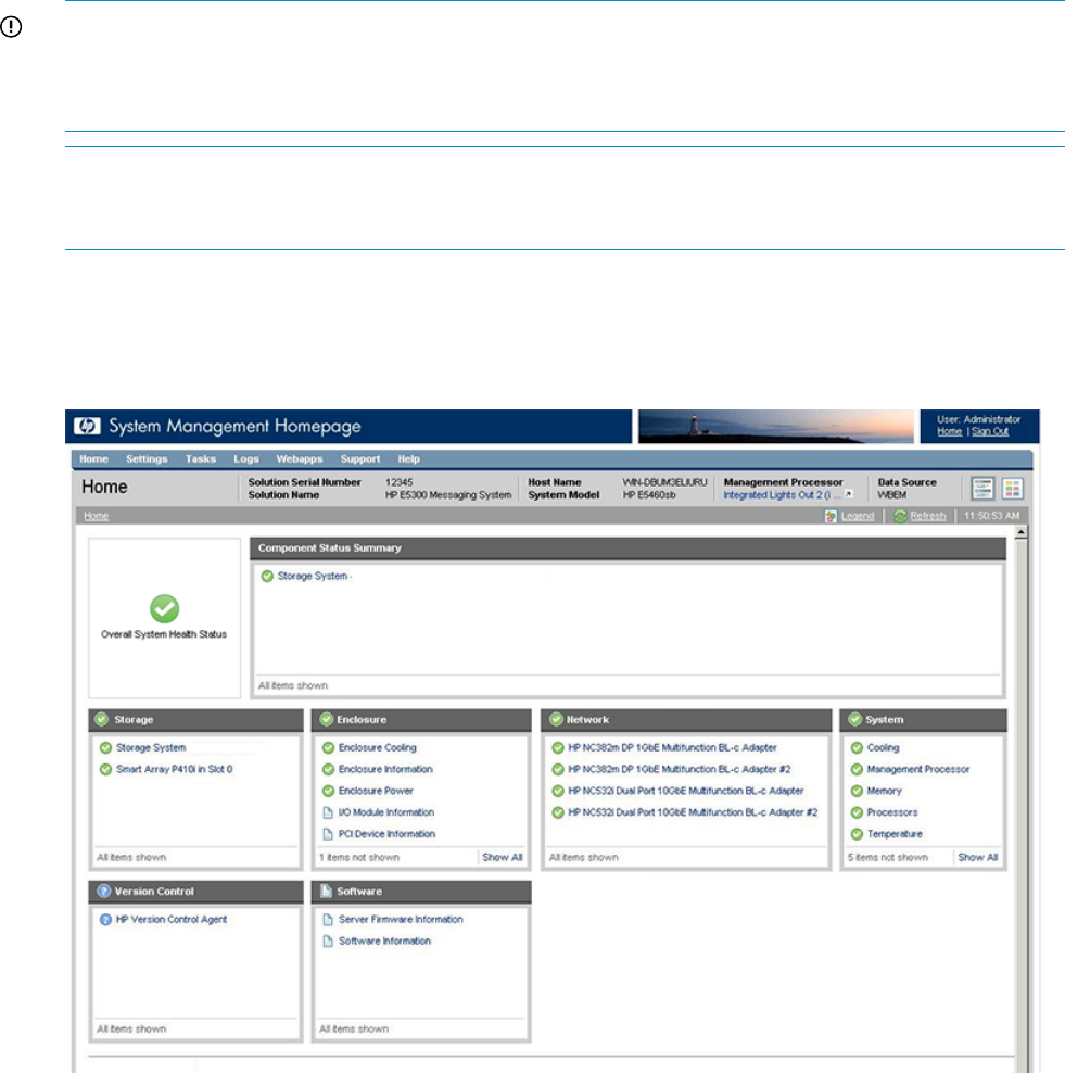
Starting the System Management Homepage application
To start the application, double-click the HP System Management Homepage desktop shortcut or
enter https://hostname:2381/ in Internet Explorer. The hostname can be localhost or
the IP address of the server you want to monitor. To log into SMH, enter the same username and
password you use to log in to the server. Users who have administrative privileges on the server
have the same privileges in the SMH application.
IMPORTANT: You must complete the E5000 Configuration Wizard before using the System
Management Homepage. During the initial stages of the installation, the Administrator user password
is not set. You cannot use the System Management Homepage to manage the messaging system
until you log in.
NOTE: To view the SMH of one server on a different server, you must modify Windows firewall
settings. For instructions, open the Help menu, select Getting Started and then Configuring Firewall
Settings.
System Management Homepage main page
Figure 10 (page 49) shows the SMH main page.
Figure 10 System Management Homepage main page
The page provides system, subsystem, and status views of the server and displays groupings of
systems and their status.
HP System Management Homepage 49
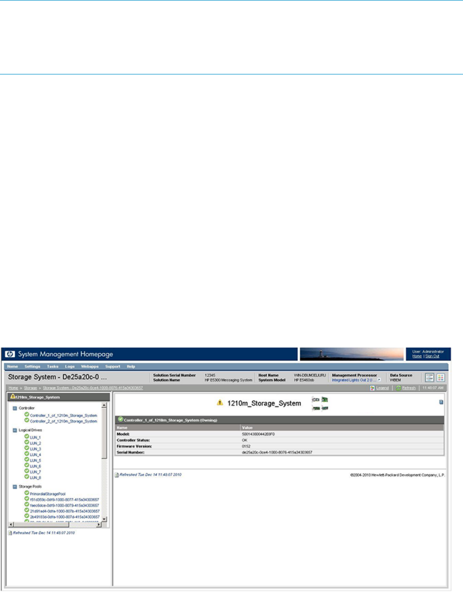
NOTE: When you remove a disk or disconnect a cable, the System Management Homepage
GUI might not display alerts when you click the Refresh button. You can force a hard refresh by
clicking the Home button or by drilling down to the problem area. The default refresh interval is 2
minutes. To change the interval in the Settings menu, select Autorefresh, and then Configure Page
refresh settings. The minimum interval is 5 seconds and the maximum is 30 minutes.
Overall System Health Status
A webapp sets the value of the Overall System Health Status icon by using a predefined heuristic.
If no webapp can determine the status, the worst possible status is displayed in the Component
Status Summary section.
Component Status summary
The Component Status Summary section displays links to all subsystems that have a critical, major,
minor, or warning status. If there are no critical, major, minor or warning items, the Component
Status Summary section displays no items.
Storage
This section displays information about the following components:
•Storage System — Links to the page that displays information about internal and external
storage subsystems.
•Smart array subsystem — Links to the page that displays information about operating system
drives and smart array controllers.
The Storage System page is organized as a left panel and a main page:
The left panel provides links to information about the following items:
•Storage Controller — Select a storage controller to view its type, status, firmware version, and
serial number.
•Logical Drives (Storage Volumes)
A list of logical drives associated with the controller appears in the left panel tree view. Select
one of the logical drive entries to display the status of the drive, fault tolerance (RAID level),
and capacity (volume size). A link to the logical drive storage pool is also displayed.
50 Monitoring and troubleshooting the messaging system

•Storage Pools
A list of storage pools associated with the controller displays in the left panel tree view. Select
one of the pool entries to display its status, capacity, communication status with the controller,
primordial state, and cache properties.
NOTE: If read or write cache is enabled the value displayed is 2; otherwise, the value is 3.
The Storage Pools page also displays a list of disk drives and storage volumes present in the
pool.
Under the Physical Drives tree, the list of expansion nodes is displayed. Under each enclosure,
the list of disk drives present in each expansion node is displayed. When there is no drive in
the enclosure, the display shows Bay Bay number – Empty. Select one of the expansion
nodes or disk drives to see information for that enclosure or drive.
•Disk Drives
This section provides an overview of all disk drives attached to the controller. Each physical
drive is listed as a separate entry in the Storage System submenu. Select any of the physical
drives to display more information about the drive.
Enclosure
This section provides information about the enclosure cooling, IDs, power, Unit Identification LED,
PCIe devices, and I/O modules.
•Because both a system and drive fan are required, the maximum and minimum number of
fans required is “2”. If either fan becomes degraded, the system could shut down quickly.
Because the fans are not mutually redundant, even if the status of a single fan has changed,
the new status is reported immediately in the SMH main page Components Status Summary.
•When the Enclosure Manager IP address is set incorrectly, the enclosure status displayed is
Lost communication. Because the Enclosure Manager has lost communication with the external
network, none of the other items in the Enclosure Information section can be displayed.
Network
This section shows the status of the network connections.
System
This section displays status for various system components.
Version Control
This section provides information about the Version Control Agent.
Software
This section provides information about system firmware and software.
Component LEDs
LEDs indicate the status of hardware components. This section provides images of the component
LED locations and describes the status of LED behaviors. To obtain additional information on some
status indicators, you can use the EMU CLI SHOW commands described in “EMU reference” (page
153).
Component LEDs 51
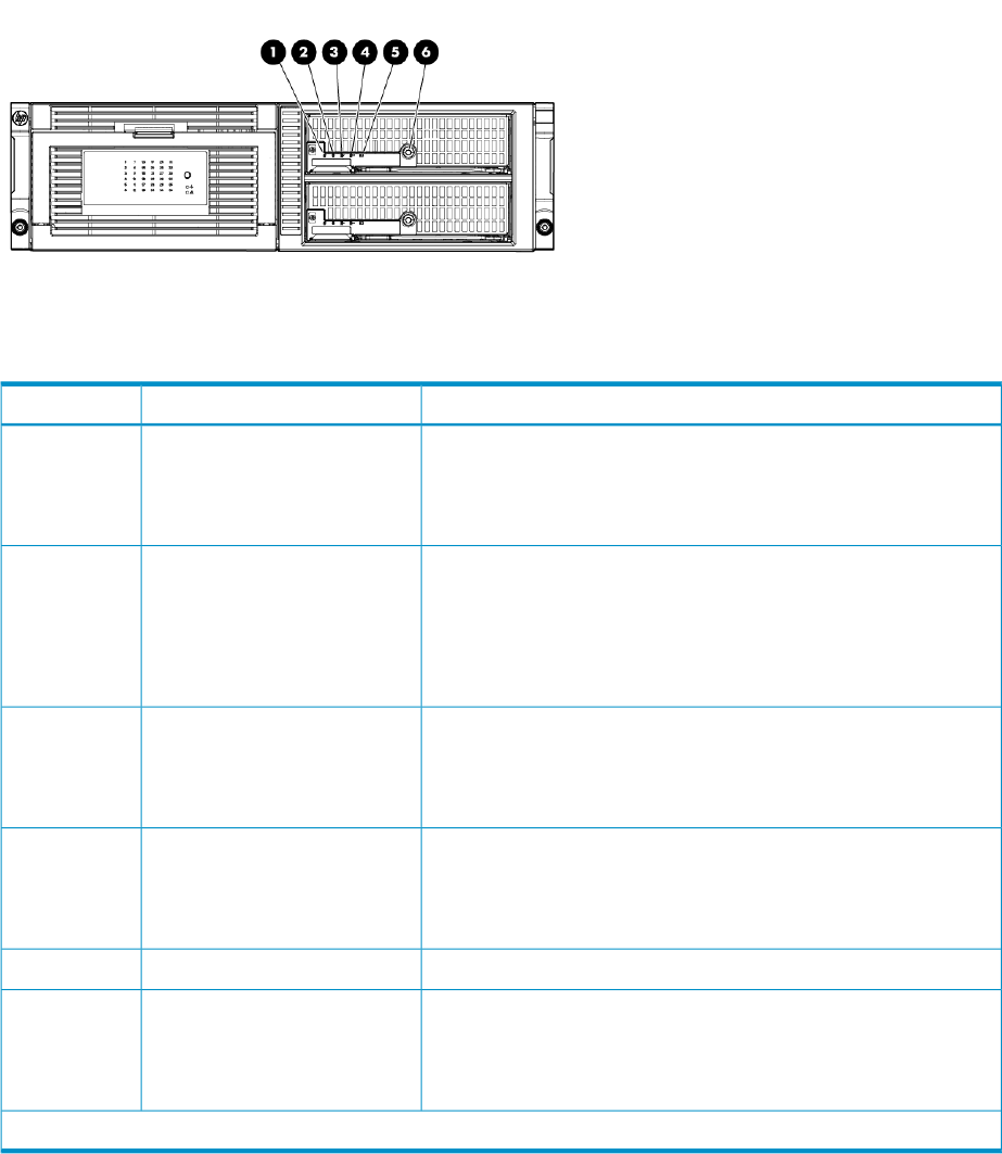
Figure 11 Server blade(s) LEDs
Table 3 Server blade LEDs status
StatusDescriptionItem
Blue = Needs service checkUID LED1
Blue flashing = remote management (remote console in use via iLO)
Off = No remote management
Green = NormalHealth LED2
Flashing = Booting
Amber = Degraded condition
Red = Critical condition
Green = Network linkedNIC 1 LED*3
Green flashing = Network activity
Off = No link or activity
Green = Network linkedFlex-10 NIC 2 LED*4
Green flashing = Network activity
Off = No link or activity
—Reserved5
Green = OnSystem power LED6
Amber = Standby (auxiliary power available)
Off = Off
*Actual NIC numbers depend on several factors, including the operating system installed on the server blade.
52 Monitoring and troubleshooting the messaging system
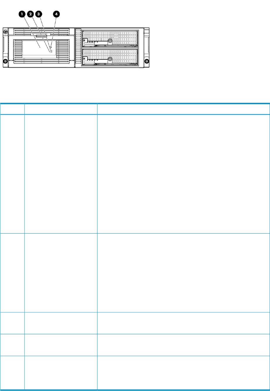
Figure 12 Front LED display board
Table 4 Front LED status descriptions
StatusDescriptionItem
Green = The drive is online, but is not currently active.Hard drive LEDs1
Flashing irregularly green = The drive is and it is operating normally.Normal mode (UID LED is
solid)
Flashing green (1 Hz) = Do not remove the drive. Removing the drive may
terminate the current operation and cause data loss. The drive is rebuilding,
or it is part of an array that is undergoing expansion, logical drive extension,
a stripe size migration, or RAID migration.
Flashing amber/green = Drive is configured and indicating a predictive
failure. The drive may also be undergoing a rebuild, expansion, extension,
or migration.
Flashing amber (1 Hz) = A predictive failure alert has been received for
this drive. Replace the drive as soon as possible.
Amber = Drive failure, link failure, or mismatched configuration.
Off = The drive is offline, a spare, or not configured as part of an array.
Green = The drive has been selected by a management application and it
is operating normally.
Hard drive LEDs1
Flashing amber (1 Hz) = The drive is not selected and is indicating a
predictive failure.
Drive locate mode (UID LED is
flashing)
Flashing amber/green = The drive has been selected by a management
application and is indicating a predictive failure.
Amber = The drive might or might not be selected and is indicating drive
failure, link failure, or mismatched configuration.
Off = The drive is not selected.
Flashing smber if there is a failed component in the system.Chassis fault LED2
OFF if the system is in good health.
Solid green if the system is in good health.Chassis health LED3
OFF if there is a failed component in the system.
This is either blue or off. When on it can be steady or blinking. Used only
for unit identification. To set the LED, use the following CLI command: SET
ENCLOSURE UID { ON | OFF | SLOW | FAST }
Chassis UID LED4
Off = Enclosure is functioning normally.
Component LEDs 53
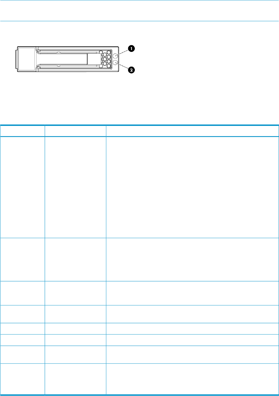
NOTE: All these LEDs are off if the enclosure has power but is turned off (see Table 11 (page
57)). Then only the equivalent Chassis LEDs (2,3,4) on the rear Power Pod shows status.
Figure 13 Hard drive LEDs
1. Fault/UID LED (amber/blue)
2. Online LED (green)
Table 5 SAS hard drive LED combinations
StatusDescriptionItem
Green = Force Off (override drive activity output). Drive is not a member
of any RAID volumes <or> Drive is configured but in a replacement or
failed state for at least one volume that is a member of a RAID volume
<or> Drive is a spare drive that is inor has been activated but has not
been rebuilt.
nl
<and>
nl
Drive is not rebuilding
nl
<and>
nl
Drive is not a member of a volume undergoing capacity expansion or
RAID migration.
Activity/0nline LED1
Solid green = Drive is a member of a RAID volume <and> Drive is not
an inspare drive <and> Drive is not in a replacement or failed state for
any volumes that is a member of a RAID volume <and> Drive is not
currently performing I/O.
Blinking green (@ 4 Hz 50% of duty cycle) = Drive is currently performing
I/O activity <and> Drive is a member of a RAID volume <and> Drive is
not in a replacement or failed state for any volumes that it is a member
of a RAID volume (drive is online) <and> Drive is not rebuilding <and>
Drive is not a member of a volume undergoing capacity expansion or
RAID migration.
Blinking green (@1 Hz 50% duty cycle — override drive activity output)
= Drive rebuilding <or> member of volume undergoing Capacity
Expansion/RAID Migration.
Off = Drive is not failed <and> Drive is not selected (unit identification).Fault/Identification LED
– Bicolor amber/blue
2
Solid blue = Drive is not failed <and> Drive is selected (unit identification).
Solid amber = Drive is failed <and> Drive is not selected.
Blinking amber (@ 1Hz 50% duty cycle) =Drive is in a predictive failure
state <and> Drive is not failed <and> Drive is not selected.
Blinking alternate amber/blue (@ 1Hz 50% duty cycle) =Drive Failed
<or> Drive is in a predictive failure state
nl
<and>
nl
Drive is selected.
54 Monitoring and troubleshooting the messaging system
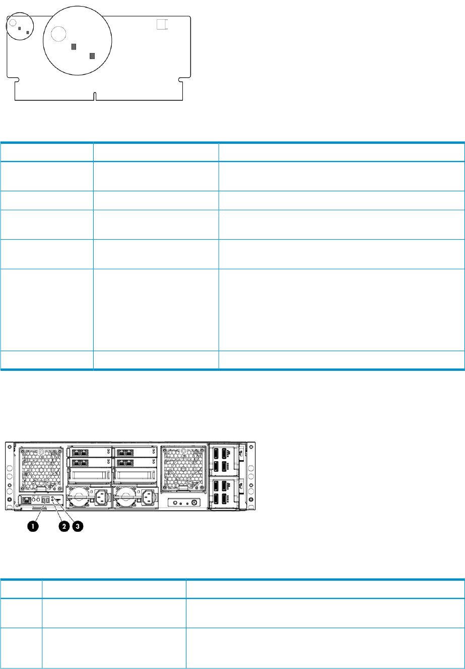
Figure 14 Cache module controller LEDs
Table 6 Cache module ontroller LED status description
StatusDescriptionItem
Green off, amber on = A backup is in progress.Controller LEDsGreen LED upper left;
Amber LED lower right
Green flashing (1 Hz), amber on = A restore is in progress.
Green flashing (1 Hz), amber off = The capacitor pack is
charging.
Green on, amber off = The capacitor pack has completed
charging
Green flashing (2 Hz) alternating with amber; amber flashing
(2 Hz) alternating with green LED = One of the following
condition exists:
nl
– The charging process has timed out.
nl
– The capacitor pack is not connected.
Green on, amber on = The flash code image failed to load.
Green off, amber off = The flash code is corrupt.
Figure 15 Enclosure Manager unit LEDs
Table 7
StatusDescriptionItem
The LED blinks during power-up, but then the display only changes in
response to commands from the Enclosure Manager Display
EM display1
Amber flashing/green LED off = issue. Use the CLI commands SHOW
ENCLOSURE STATUS and SHOW SYSLOG EM to determine possible
fault causes.
EM fault LED2
Component LEDs 55
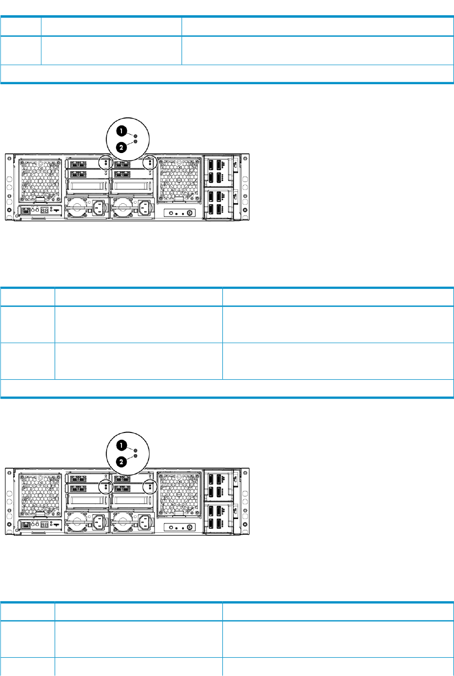
Table 7 (continued)
StatusDescriptionItem
The health LED is only green and is either on (Healthy) or off (Power
off or Faulted).
EM health LED3
LEDs are off when the enclosure is powered off.
Figure 16 HP StorageWorks 2-port 1 Gb Ethernet I/O modules LEDs
Table 8 HP StorageWorks 2-port 1 Gb Ethernet I/O modules LEDs status description
StatusDescriptionItem
Solid green when module health is goodModule health LED1
Off* when module has failed
Solid amber when module has failedModule fault LED2
Off* when module health is good
*LEDs are off when enclosure is powered off.
Figure 17 HP StorageWorks 2-port 1 Gb Ethernet, Mezz A and B I/O modules LEDs
Table 9 HP StorageWorks 2-port 1 Gb Ethernet, Mezz A and B I/O modules LEDs status description
StatusDescriptionItem
Solid green when module health is goodModule health LED1
Off* when module has failed
Solid amber when module has failedModule fault LED2
56 Monitoring and troubleshooting the messaging system
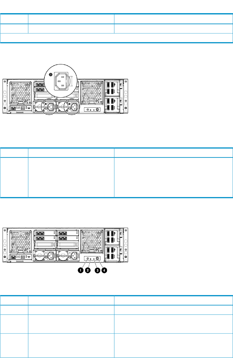
Table 9 HP StorageWorks 2-port 1 Gb Ethernet, Mezz A and B I/O modules LEDs status description
(continued)
StatusDescriptionItem
Off* when module health is good
*LEDs are off when enclosure is powered off.
Figure 18 Power supply LEDs
Table 10 Power supply LED status description
StatusDescriptionItem
Green = Power on and power supply functioning properlyPower supply1
Off = One or more of the following conditions exists: System
powered off, AC power unavailable, Power supply failed,
Power supply exceeded current limit. Use the CLI command
SHOW ENCLOSURE POWERSUPLY STATUS ALL for more
details.
Figure 19 Chassis switches and indicator LEDs
Table 11 Chassis switches and indicator LED status description
StatusDescriptionItem
Solid blue = Requires service check.UID1
Solid green when system health is good.Chassis health2
OFF if a module or component in the system has failed
Flashing amber if a module or component in the system has
failed.
Chassis fault3
OFF if system health is good.
Component LEDs 57
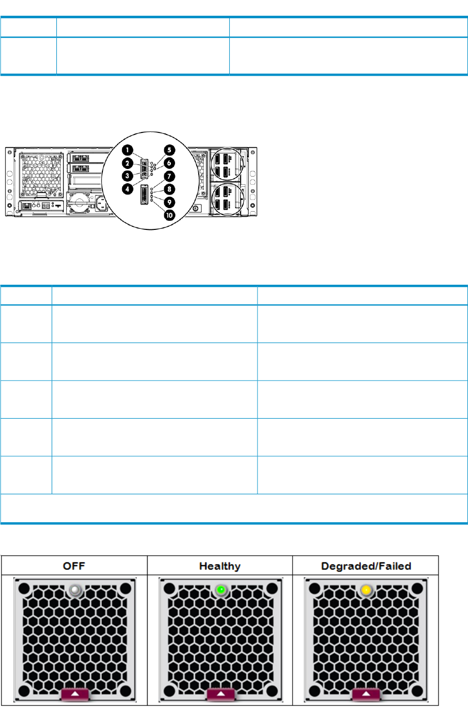
Table 11 Chassis switches and indicator LED status description (continued)
StatusDescriptionItem
Green when enclosure power is ON.Power button/LED4
Amber when enclosure has AC power but is turned off.
Figure 20 SAS I/O modules LEDs
Table 12 SAS I/O module LED status description
StatusDescriptionItem
Green* = HealthySAS Port 11, 2
Amber = Issue
Green* = HealthySAS Port 23, 4
Amber = Issue
Green = HealthyOverall I/O module status5, 6
Amber = Issue
Green* = HealthySAS Port 37, 8
Amber = Issue
Green* = HealthySAS Port 49, 10
Amber = Issue
*If there is anything connected to a connector, the corresponding green LED is on and blinks offwith activity. If there
is nothing connected to a connector, both LEDs are off. The error LED is not currently being used and is always off.
Figure 21 Fan LEDs
58 Monitoring and troubleshooting the messaging system
The two fan modules are physically identical, but their control is not. The Fault/health LED on FAN
1 is a single bi-color LED controlled by the EMU via the Health Monitor – it is either off, steady
green, or flashing amber. The lens of the fan LED is colorless and looks grayish-white when off.
System Fan — Fan 1
Fan 1 LED is driven by the Health Monitor PSoC under direction of the EMP firmware. The fan
microprocessor inside the Fan module cannot sense or control this LED. If the EMU fails, or if the
connection between the EMU and the fan fails, the LED cannot be controlled and thus may not
reflect actual state. Also, because Fan 1 LED has no power unless enclosure power is on, the EMP
cannot indicate Fan status in standby mode.
Unlike the EMU health LED circuit, there is no autonomic hardware circuit controlling the FAN Fault
LED. Assuming the LED is working, it flashes Amber by the EMU if one or two of the 3 fan rotors
is not functioning, or if the microprocessor on the fan module is unresponsive, or if MFG NVRAM
on the module is unreadable.
Drive Fan — Fan 2
The Fault/health LED on FAN 2 is not controlled at all by the EMU – but is controlled by one of
the management processors inside the SAS IO Module. This LED cannot be lit without enclosure
power ON, and its state depends upon signals from one of the SAS IO modules.
To troubleshoot a degraded fan, you can use the EMU CLI commands SHOW ENCLOSURE STATUS
and SHOW ENCLOSURE FAN ALL described in “EMU reference” (page 153).
EMU CLI SHOW commands
Use the EMU CLI SHOW commands described in “EMU reference” (page 153) to obtain additional
information about component status as indicated by the hardware LEDs described in “Component
LEDs” (page 51). To access the CLI, log in to the EMU as Administrator.
The system is shipped with a single enabled user account: Administrator. The password of the
Administrator account is unique, programmed at the factory, and printed on the tear-off label on
the back of the unit and the label on top of the EMU. Logging in to the system requires the Secure
Shell protocol (SSH). Windows systems can use ssh clients such as PuTTy, which can be freely
downloaded.
To log in to the EMU:
1. Note the IP address of the EMU.
2. ssh to the EMU.
3. Log in as Administrator.
Following is a sample login session.
[user@host ~]$ ssh Administrator@10.0.0.10
-----------------------------------------------------------------------------
WARNING: This is a private system. Do not attempt to login unless you are an
authorized user. Any authorized or unauthorized access and use may be moni-
tored and can result in criminal or civil prosecution under applicable law.
-----------------------------------------------------------------------------
User: /src/bin/build@msaonyx
Script: ./parbuild
Directory: /src/quire/QUIRE-IDP-1-0/daily/2010110801/bld/QUIRE-IDP-1-0
FileTag: 110820102003
Date: 2010-11-08T20:03:55
Firmware Output: jsbach
Firmware Version: 0x0100
SVN Version: 2452
Administrator@10.0.0.10's password:
HP IDP System Enclosure Manager
(C) Copyright 2006-2009 Hewlett-Packard Development Company, L.P.
EMU CLI SHOW commands 59

Type 'HELP' to display a list of valid commands.
Type 'HELP <command>' to display detailed information about a specific command.
Type 'HELP HELP' to display more detailed information about the help system.
EM 78E7D1020504>
After logging in, you can set the Administrator password by running the HP-provided tool,
nl
C:\Program Files\HP\HP Configuration Wizard\HPEMConfig.exe.
HP Support websites
Use the “Support and troubleshooting” task at the HP Support & Drivers website
nl
(http://www.hp.com/go/support) to troubleshoot problems with the messaging system. After
entering the messaging system name and designation (for example, E5300 Messaging System)
or component information (for example, SAS I/O module), use the following links for troubleshooting
information:
•Download drivers and software—This area provides drivers and software for your operating
system.
•Troubleshoot a problem—This area provides a listing of customer notices, advisories, and
bulletins applicable for the product or component.
•Manuals—This area provides the latest user documentation applicable to the product or
component. User guides can be a useful source for troubleshooting information. For most
messaging system hardware platforms, the following ProLiant server manuals may be useful
for troubleshooting assistance:
◦HP ProLiant Server User Guide or HP ProLiant Server Maintenance and Service Guide
These guides contain specific troubleshooting information for the server.
◦HP ProLiant Servers Troubleshooting Guide
The guide provides common procedures and solutions for many levels of troubleshooting
with a ProLiant server. For E5000 guides, go to www.hp.com/support/manuals, select
Solutions appliances in the solutions groups, and select an E5000 product.
IMPORTANT: Some troubleshooting procedures found in ProLiant server guides may not apply
to the messaging system. If necessary, check with your HP Support representative for further
assistance.
For software-related components and issues, online help or user guide documentation may offer
troubleshooting assistance. The release notes for the messaging system product line is frequently
updated. The document contains issues and workarounds to a number of categories for the
messaging systems.
Known issues and workarounds for the messaging system products and the service release are
addressed in release notes.
HP Insight Remote Support software
HP strongly recommends that you install HP Insight Remote Support software to comple the installation
or upgrade of your product and to enable enhanced delivery of your HP Warranty, HP Care Pack
Service, or HP contractual support agreement. HP Insight Remote Support supplements your
monitoring, 24x7 to ensure maximum system availability by providing intelligent event diagnosis,
and automatic, secure submission of hardware event notifications to HP, whichinitiates a fast and
accurate resolution, based on the service level of your product. Notifications may be sent to your
authorized HP Channel Partner for on-site service, if configured and available in your country. The
software is available in two variants:
•HP Insight Remote Support Standard: This software supports server and storage devices and
is optimized for environments with 1 to 50 servers. Ideal for customers who can benefit from
60 Monitoring and troubleshooting the messaging system

pronotification, but do not need proservice delivery and integration with a management
platform.
•HP Insight Remote Support Advanced: This software provides comprehensive remote monitoring
and proservice support for nearly all HP servers, storage, network and SAN environments,
plus selected non-HP servers than have a support obligation with HP. It is integrated with HP
Systems Insight Manager. A dedicated server is recommended to host both HP Systems Insight
Manager and HP Insight Remote Support Advanced.
Details for both versions are available at:
http://www.hp.com/go/insightremotesupport
To implement Insight Remote Support for E5000 systems, follow the instructions in release A.05.50
or later of the following guides:
•HP Insight Remote Support Standard Hosting Device Configuration Guide (for standard support)
•HP Insight Remote Support Advanced CMS Configuration and Usage Guide (for advanced
support)
To obtain these guides:
1. Go to the Insight Remote Software website (previously cited).
2. From the Learn More menu, select either Insight Remote Standard or Insight Remote Support
Advanced software.
3. Select Support Documentation.
Be aware of the following specifics for E5000 systems:
•The messaging system is a "managed system" as described in Insight Remote Support guides.
•The E5460sb is equivalent to a ProLiant server and meets all the requirements for a managed
system.
•The messaging system hardware is preconfigured for Insight Remote Support and uses the
WMI (WBEM) provider, not SNMP, to communicate with the CMS.
•Insight Remote Support Software is preinstalled on the E5000 systems.
•For Insight Remote Support Advanced, register the system using the E5000 part number and
serial number (not the blade name).
Confirm and overwrite any pre-populated values with the serial number of the messaging
system. The part number and serial number are located on the pullout tab at the EMU on the
back of the messaging system.
•You will need to register WBEM access credentials in HP SIM.
Microsoft Systems Center Operations Manager
Microsoft Systems Center Operations Manager (SCOM) provides comprehensive monitoring,
performance management, and analysis tools to maintain Windows OS and application platforms.
This solution allows you to monitor Microsoft Windows environments and HP storage products
through a common OpsMgr console. To download HP management packs for Microsoft System
Center Operations Manager, including installation, configuration, and usage documentation, visit
the HP StorageWorks Management Packs for Microsoft Systems Center site at
nl
www.hp.com/go/storageworks/scom2007.
Obtaining the Service Agreement ID (SAID)
Obtain the SAID from your service contract agreement and keep it in a secure location. You must
provide it when you contact HP Support.
Microsoft Systems Center Operations Manager 61
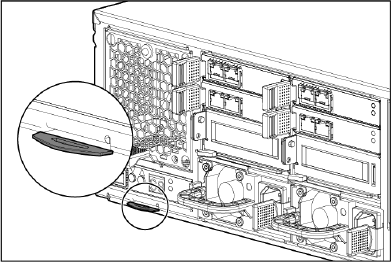
Locating the messaging system warranty entitlement labels
You must locate and identify the serial number and part number for the messaging system
components to obtain service under the warranty. The numbers are listed on the warranty entitlement
label located on the pull-out tab that is positioned below the Enclosure Management module, in
the lower left-hand corner of the back of the enclosure.
Figure 22 Location of warranty entitelment labels
62 Monitoring and troubleshooting the messaging system

6 Updating system software and firmware
This section explains how to update system software and firmware.
Powering off the messaging system
Follow these steps whenever you need to shut down a single server blade or to perform a system
shutdown of the messaging system:
1. Go to the standard Windows path of Start > Shut Down.
2. Shut down blade 2.
3. Shut down blade 1.
4. Power off any disks in expansion enclosures by pressing and holding down the power button
located on the back of each expansion disk.
5. Power off the messaging system enclosure by pressing and holding down the power button
located on the back of the enclosure.
6. Disconnect the power cables (optional).
To power on the server blades and messaging system, reverse the shutdown procedure.
Determining the current messaging system software version
To determine the current software version running on a server blade, follow these steps:
1. Log in to the server blade.
2. Open a command window.
3. Enter the reg query command as shown in the following example:
C:\> reg query HKLM\Software\Wow6432Node\Hewlett-Packard\StorageWorks\QuickRestore /s
HKEY_LOCAL_MACHINE\Software\Wow6432Node\Hewlett-Packard\StorageWorks\QuickRestore
BASE REG_SZ 2.0.1.21
QRVersion REG_SZ 2.00.1a.226
Revision REG_SZ A
ConfigXML REG_SZ 2.0
Updating the messaging system software
HP recommends that you update the messaging system software as part of normal system
maintenance. Regular updates are available at www.hp.com. Updates might also be necessary
when replacing a server blade or other component. To update the software:
1. Go to www.hp.com.
2. Select Support & Drivers.
3. Select Download drivers and software (and firmware).
4. Enter E5000 in the for product box and click the button.
5. Go to the Software→System Management section and select the current version of the HP
E5000 Update download.
6. Copy the file HPE5000Update_x_y_z.exe (where x,y, and zare the current version
numbers) to Server 1 and double-click. Wait for a few seconds for the program to extract.
7. The E5000 Software Update user interface appears, directing you not to reboot during the
update.
8. Press OK to start.
9. The update runs in the background and takes a few minutes to complete.
10. After the update completes, the user interface reports success and lists the installed programs:
Powering off the messaging system 63
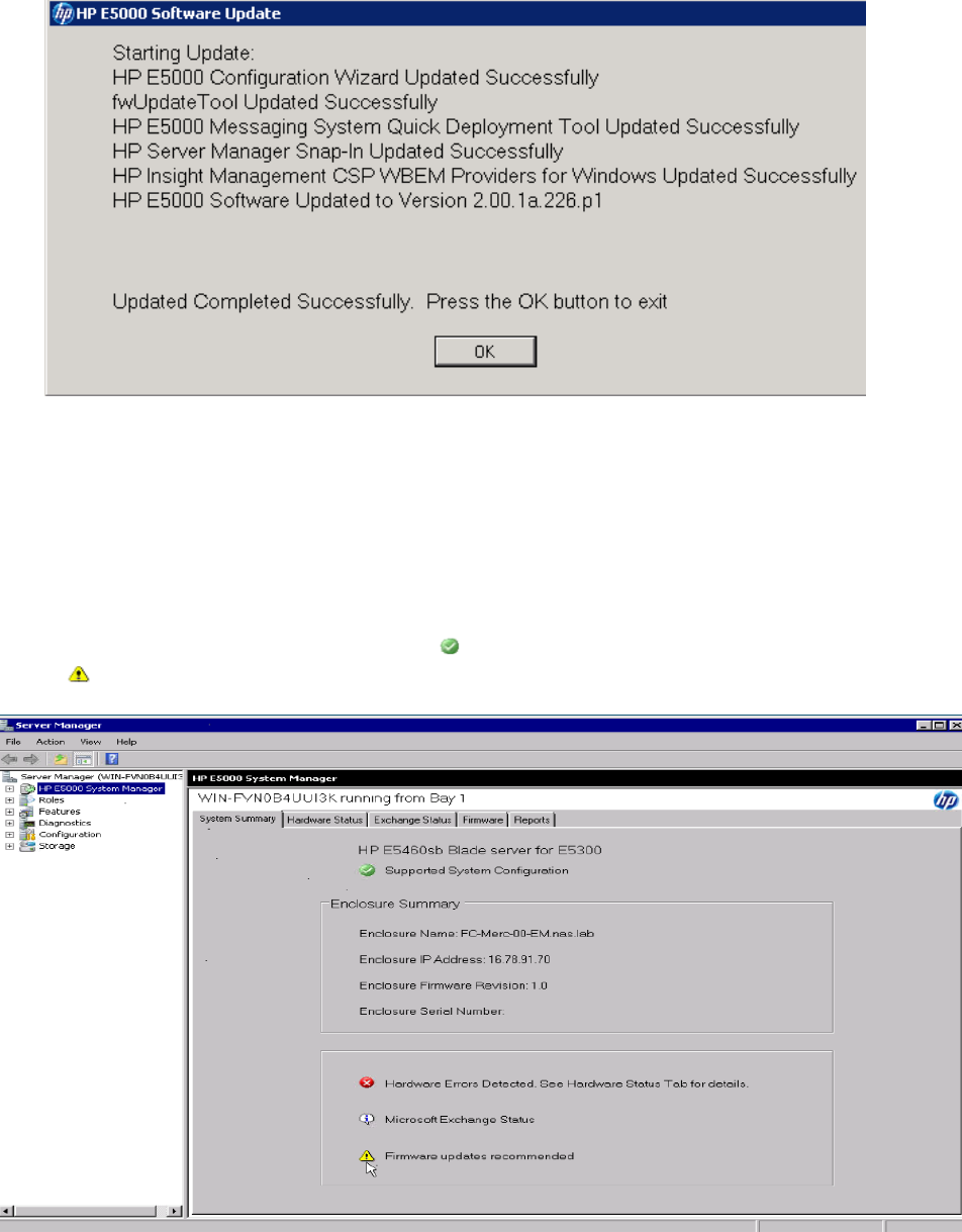
11. Press OK to exit.
12. After Server 1 has completed the update, copy the file HPE5000Update_x_y_z.exe to
Server 2 and repeat the update procedure.
Upgrading a component's firmware version
To determine whether a component requires a firmware upgrade, select the E5000 System Manager
in Microsoft Server Manager. Click the System Summary tab, and inspect the Firmware update
recommended icon status. If the icon is green , no firmware update is needed. If the icon is
yellow , a firmware update is required.
If a firmware update is needed, click the E5000 System Manager Firmware tab to view the
Components Available for Updates window for a list of the components that can be upgraded.
64 Updating system software and firmware
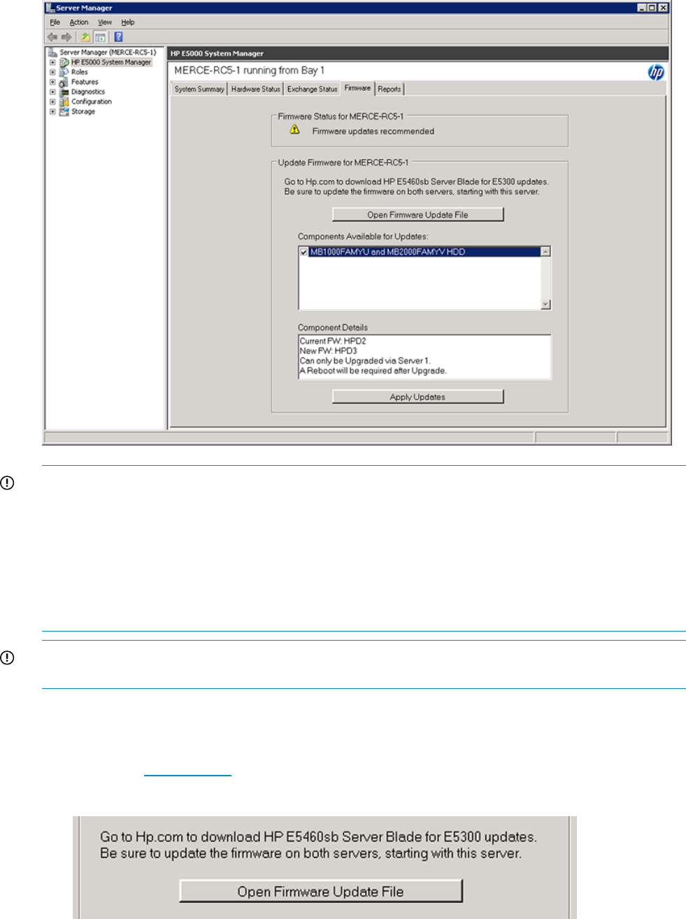
IMPORTANT: You must check for firmware version upgrades on each server blade. Certain
upgrades may only be performed on Server Blade 1, Bay 1, and other component firmware version
upgrades may appear only on Server Blade 2, Bay 2.
IMPORTANT: Firmware upgrades may impact information availability on the server blades during
the upgrade. For instance, you cannot access information on the drives while they are updating.
You need to gracefully shut down the messaging system for availability during the upgrade. If a
component requires an upgrade to multiple shared components, such as the hard drives, followed
by a reboot, the data is unavailable for a longer period of time.
IMPORTANT: You must repeat the steps in this section for each server blade in the messaging
system. Use Server 1, Bay 1 to update all components except for those in Server 2, Bay 2.
To check for component firmware version upgrades:
1. From the System Manager Firmware tab, follow the instructions under Update firmware for
[Server Blade Name]:
a. Go to www.hp.com and enter the product name (for example, E5300 Messaging System).
b. Download the available firmware upgrades to your typical server download location.
2. Click the Open Firmware Update File button.
This action places the downloaded firmware bundle into the appropriate folder on the
messaging system and then automatically refreshes the System Manager.
Upgrading a component's firmware version 65

3. In the Components Available for Upgrades window, select the box next to each component
to be upgraded. The Component Details box displays the firmware version that is currently
running, and the available firmware version.
NOTE: HP recommends that you upgrade one component at a time to ensure each version
updates successfully.
Carefully shut down Server 2, Bay 2 before using Server 1, Bay 1 to update the drives in the
drawer.
4. After selecting the components for update, click Apply Updates. The status reports that an
upgrade is in progress.
66 Updating system software and firmware
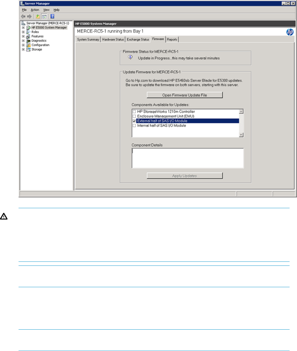
WARNING! When updating both controllers at the same time, you must update the firmware
to sync it with the pared-down controller. This step takes the volumes offline because both
pared-down servers must reboot. When the volumes go down, an auto-clone operation occurs,
which means the firmware of the running controller is flashed onto the booting controller. This
ensures that both controllers are running the same firmware version. If you have iSCSI, be
sure to disconnect before beginning a firmware update.
NOTE: Each firmware upgrade takes a few minutes to complete. If you are upgrading
multiple components, such as hard drives, the upgrade takes more time.
5. Reboot the server blade, if needed.
A message appears in the Component Details window to alert you if a reboot is required after
each component firmware upgrade. After the upgrade completes, the Firmware Status changes
from “Firmware updates recommended” to “A reboot is required.”
NOTE: If a reboot is not required after the component firmware upgrade completes, the
component name no longer appears in the Components Available for Upgrades box.
If a reboot is required, follow these steps after the firmware upgrade completes:
a. Click Start, click the power option flyout, and then select restart.
b. Complete the Windows Shutdown Event Tracker.
c. Click OK.
6. Verify the success of the firmware upgrade by viewing the Firmware Status. You can also
confirm the firmware upgrade success by viewing the System Summary.
Upgrading a component's firmware version 67
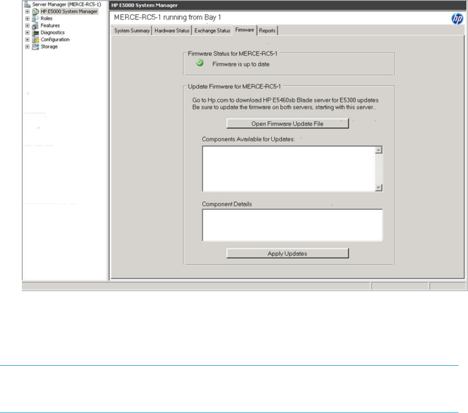
The System Manager automatically notifies you when a firmware upgrade is available for an
component. If a replacement component is running an earlier firmware version, the System Manager
alerts you on the System Summary and Firmware tabs. In this instance, you do not need to download
a firmware upgrade.
NOTE: The firmware upgrade has failed if a component remains in the Components Available
for Updates list after the firmware upgrade and reboot. To identify the next steps needed for
successful firmware upgrade, go to the Reports tab (see “Reports” (page 47)) and run a report.
The possible components that can be identified in the Components Available for Updates include
the following:
•Integrated Lights-Out (iLO)
•HP StorageWorks 1210m Controller
•Systems ROM (I24) for HP E5460sb Server Blade
•Power Management Controller Firmware (c-Class Blades)
•Smart Array P410i Blade HDD Controller
•Enclosure Manager Unit (EMU)
•External half of SAS I/O Module
•Internal half of SAS I/O Module
•HP E5000 expansion node I/O Module
•MBFAM1000YU and MBFAM2000YV HDD
68 Updating system software and firmware
7 Removing and replacing hardware components
This chapter describes procedures for removing and replacing hardware components.
Customer self repair
HP customer self repair (CSR) programs allow you to repair your StorageWorks product. If a CSR
part needs replacing, HP ships the part directly to you so that you can install it at your convenience.
Some parts do not qualify for CSR. Your HP-authorized service provider determines whether a
repair can be accomplished by CSR.
For more information about CSR, contact your local service provider, or see the CSR website:
http://www.hp.com/go/selfrepair
Best practices for replacing components
The following sections provide information to help you successfully replace the hardware components
on your messaging system.
WARNING! To reduce the risk of personal injury or damage to the equipment:
•Be sure that only one component is extended from a rack at a time. A rack may become
unstable if more than one component is extended at the same time.
•Do not extend the hard drive drawers beyond the supporting surface when the unit is not
installed in a rack.
CAUTION: Removing a component significantly changes the air flow within the enclosure. All
components must be installed for the enclosure to cool properly. If a component fails, leave it in
place in the enclosure until a new component is available for installation.
During replacement of the failed component
•HP recommends waiting until periods of low messaging system activity to replace a component.
•When replacing components at the rear of the rack, cabling may obstruct access to the
component. Carefully move any cables out of the way to avoid loosening any connections.
In particular, avoid cable damage that may be caused by:
◦Kinking or bending
◦Disconnecting cables without capping. If uncapped, cable performance may be impaired
by contact with dust, metal, or other surfaces.
◦Placing removed cables on the floor or other surfaces where they may be walked on or
otherwise compressed.
Accessing component replacement videos
HP produced videos of the procedures to assist you in replacing components. To view the videos,
go to the HP Customer Self Repair Services Media Library website and navigate to your product:
http://www.hp.com/go/sml
Identifying the spare part
Parts have a nine-character spare part number on their label. For some spare parts, the part number
is available in the messaging system. Alternatively, the HP call center can assist in identifying the
correct spare part number.
Customer self repair 69
Replaceable parts
This product contains replaceable parts. To identify the replaceable parts, see the individual
component guides listed in Table 14 (page 73).
Parts that are available for CSR are indicated as follows:
•Mandatory CSR — You order the part directly from HP and repair the product yourself. On-site
or return-to-depot repair is not provided under warranty.
•Optional CSR — You can order the part directly from HP and repair the product yourself, or
you can request that HP repair the product. If you request repair from HP, you may be charged
for the repair depending on the product warranty.
•No CSR — The replaceable part is not available for self repair. For assistance, contact an
HP-authorized service provider.
For more information about CSR — contact your local service provider. For North America, see
the CSR website:
http://www.hp.com/go/selfrepair
To determine the warranty service provided for this product, see the warranty information website:
http://www.hp.com/go/storagewarranty
To order a replacement part, contact an HP-authorized service provider or see the HP Parts Store
online: http://www.hp.com/buy/parts
Figure 23 (page 71) shows an exploded view of the messaging system.
70 Removing and replacing hardware components
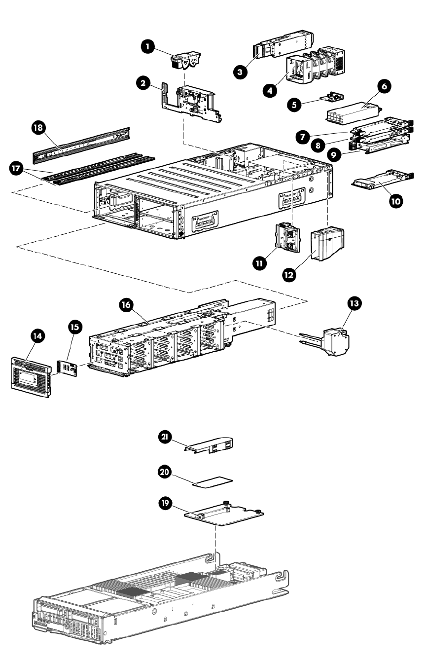

Table 13 Messaging system replaceable parts
Replacement type (Cold,
Warm, Hot)CSR availabilityPart numberReplaceable unit (RU)Item
ColdOptional631117-001Server interposer1
ColdNon631115-001Midplane board2
HotMandatory408765-001.5 M mini SAS cable(Not shown)
HotMandatory408767-001Mini SAS cable 2 M(Not shown)
HotMandatory408768-001Mini SAS cable 4 M(Not shown)
HotMandatory631941-001LFF SAS I/O module3
HotMandatory631109-001Fan modules4
ColdOptional399054-001Power UID button assembly5
HotMandatory631942-001Power supplies6
HotMandatory631110-0012-port 1 Gb Ethernet module7
HotMandatory631110-0012-port 1 Gb Ethernet module8
(E5500/E5700)
HotMandatory631134-001Mezzanine blank8 (E5300 only)
WarmOptional631942-001PCIe module9
HotMandatory631112-001Enclosure Manager module10
ColdNon631116-001Server blade backplane11
ColdNon631129-001Server airflow baffle12
ColdNon631130-001Coil power assembly13
ColdOptional631118-001Drive drawer bezel LFF14
ColdOptional631126-001LFF LED display board15
ColdOptional631128-001LFF drive drawer assembly16
HotMandatory389015-001Hard drive drawer LFF blanks(Not shown)
HotMandatory508011-0011 TB Hard drive(Not shown)
HotMandatory508010-0012 TB Hard drive(Not shown)
ColdNon631131-001Drawer rails bottom17
ColdNon631132-001Drawer rails left18
ColdNon631133-001Mezzanine NIC19
HotOptional629960-001,
629960-002,
629960-003
Right ear bezel on chassis (3,
one for each model)
(Not shown)
WarmOptional615360-0011210m controller19
WarmOptional598414-001Cache module20
WarmMandatory587225-001Supercapacitor21
ColdOptional631133-001Rail kit assembly(Not shown)
For more information on removing and replacing components, see Table 14 (page 73) for a list
of individual component documents.
72 Removing and replacing hardware components
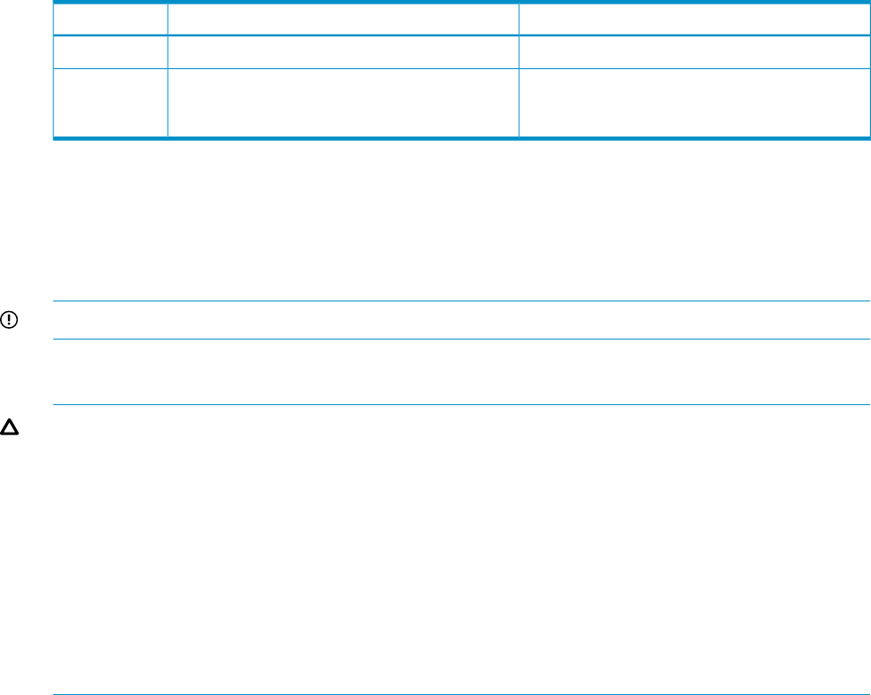
Table 14 Related component documents
GuideComponent nameComponent
BL460c maintenance and service guideE5460sb bladesServer blade
HP StorageWorks D2600/D2700 Disk Enclosure
User Guide
HP E5000 Messaging System 12 TB expansion
ode and HP E5000 Messaging System 24 TB
expansion node
Disks in
expansion
nodes
Hot, warm, and cold swap components
Hot or warm swapping a component means removing and replacing it while the main power is
still on. Cold swapping means removing and replacing the component while the main power is
off. Port (purple) colored handles on components like the fan module indicate the component is
hot-swappable.
IMPORTANT: Remove and replace components quickly without interrupting the process.
Preventing electrostatic discharge
CAUTION: Components can be damaged by electrostatic discharge (ESD). Use proper anti-static
protection.
•Always transport and store CSR replaceable parts in an ESD protective enclosure.
•Do not remove CSR replaceable parts from the ESD-protective enclosure until you are ready
to install it.
•Always use ESD precautions, such as a wrist strap, heel straps on conductive flooring, and
an ESD-protective smock when handling ESD sensitive equipment.
•Avoid touching all connector pins, leads, or circuitry.
•Do not place ESD-generating material such as paper or non anti-static (pink) plastic in an ESD
protective enclosure with ESD sensitive equipment.
Verifying component failure
Use the following methods to verify component failure:
•Analyze any failure messages received. Fault monitoring software from HP provides a
recommended action.
•Navigate to System Manager and check the System Status tab for the enclosure health status.
•Check the component status using the System Manager:
1. Open the System Manager Hardware Status tab to identify a failed component. For more
information, see “Hardware Status” (page 44).
2. To identify the correct enclosure, start the System Management Homepage application
as described in “ Starting the System Management Homepage application” (page 49),
select Unit Identification Device from the Enclosure pane, and then select the On radio
button on the Unit Identification Device screen. This causes the blue UID indicator to blink
on the controller enclosure.
Hot, warm, and cold swap components 73

Verifying proper operation
After replacing a messaging system component, check the following to verify that the component
is operating properly:
•If applicable, verify that the green LED is lit continuously or blinking. If not, try reseating the
component.
•From the System Manager, navigate to the Hardware Status and System Summary tabs to
confirm the component failure alert no longer appears. The status should be (Good).
Wait times for hard disks
If the hard drive is part of a volume, the following wait times apply:
Removal
•Less than 3 seconds for the LED to turn off
Insert
•Less than 1 second for first disk activity
•Less than 15 seconds for the disk to be ready for REBUILD. The LED blinks at 1 Hz.
NOTE: The transition to solid green depends on how long the REBUILD takes (the LEDs
indicate REBUILD).
If the hard drive is not part of a volume, the following wait times apply:
Removal
•No indication appears because the LED is already off
Insert
•Less than 1 second for the first disk activity to appear
•Less than 15 seconds for the disk to be ready to use
Removing and replacing the server interposer board
This section describes how to remove and replace the server interposer board in the messaging
system.
Removing the server interposer board
To remove the server interposer board:
1. Use System Manager to identify the failed component.
2. Verify the failed component by checking for a blinking amber LED on the failed component
(see Table 4 (page 53)).
3. Power off the system:
1. Shut down blade 2 by clicking on Start and then Shut Down while you are connected to
blade 1.
2. Shut down blade 1 by clicking on Start and then Shut Down while you are connected to
blade 2.
3. Power off the expansion nodes, if present, by pressing and holding the power button at
the back.
4. Power off the storage solution by pressing and holding the power button at the back of
the enclosure.
5. Disconnect the power cables.
4. Extend the hard drive drawer:
74 Removing and replacing hardware components
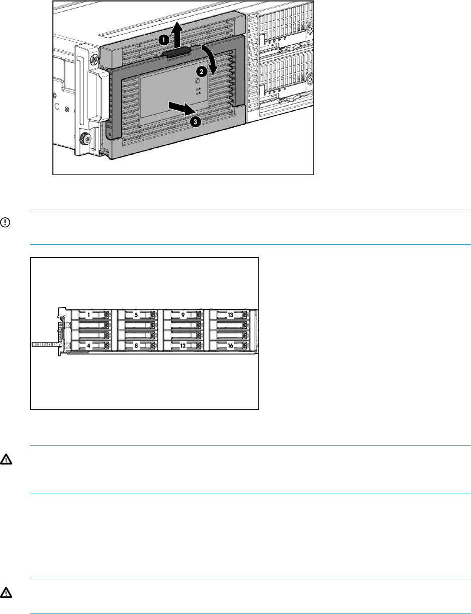
1. Press upward on the release button on the hard drive drawer (1).
2. Pull the drawer handle down 90 degrees (2).
3. Extend the hard drive drawer (3).
5. Label the hard drives.
IMPORTANT: Use the drive labels provided with the replacement server interposer board
when removing the drives to ensure you replace the drives in the correct order.
6. Remove all hard drives.
WARNING! Carefully check the drive labels provided with the replacement board, and then
install the hard drives in the same slots from which you removed them. If the drives are not
installed in the correct slots, the system might fail.
7. Push the hard drive drawer back into the messaging system enclosure.
8. Label each server blade and then remove both server blades.
9. Label the cables and then unplug all cables from the back of the messaging system enclosure.
10. Unscrew the retaining screws from the bezel ears, and then remove the enclosure from the
rack.
WARNING! The messaging system enclosure is heavy, even after removing the hard drives.
Always use at least two people to remove the messaging system from the rack.
11. Remove the top back panel by pressing the panel release button and lifting the latch to slide
the top back panel off.
Removing and replacing the server interposer board 75
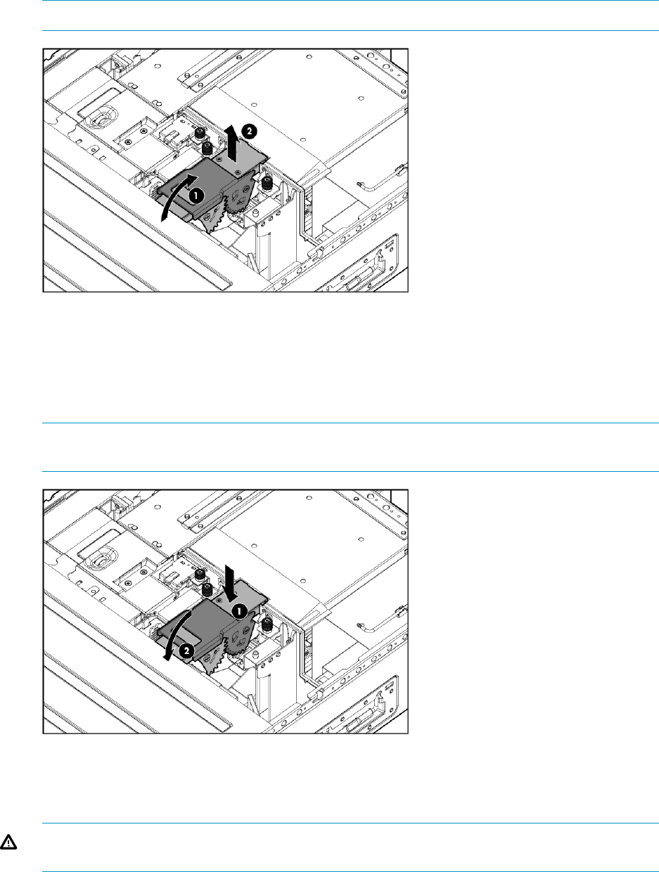
12. Open the release handle (1), and pull up to remove the server interposer board (2).
NOTE: You may need to use significant force to accomplish this task.
Replacing the server interposer board
To replace the server interposer board:
1. With the release handle open, align the server interposer board with the alignment pins (1),
and then close the server interposer release mechanism (2).
NOTE: Remember to move the server backplane power cable out of the way of the alignment
pins.
2. Reinstall the top back panel.
3. Place the enclosure into the rack, and secure the enclosure by tightening the two retaining
screws.
WARNING! The messaging system enclosure is heavy, even after removing the hard drives.
Always use at least two people to replace the messaging system in the rack.
4. Replace both server blades in their original bays.
5. Extend the hard drive drawer:
1. Press upward on the release button on the hard drive drawer (1).
2. Pull the drawer handle down 90 degrees (2).
76 Removing and replacing hardware components

3. Extend the hard drive drawer (3).
6. Replace all hard drives.
IMPORTANT: Install the hard drives in the same slots from which you removed them or the
system might fail. Use the drive labels to ensure you replace the drives in the correct order.
7. Push the hard drive drawer back into the messaging system enclosure.
8. Plug in all cables at the back of the messaging system enclosure, and ensure that all cables
are returned to their original locations.
9. Power on the messaging system by pressing the power button On.
10. Confirm that the messaging system has resumed normal operations.
Removing and replacing the midplane board
This section describes how to remove and replace the midplane board in the messaging system.
Removing the midplane board
To remove the midplane board:
1. Use System Manager to identify the failed component.
2. Verify the failed component by checking for a blinking amber LED on the failed component.
3. Power off the system:
1. Shut down blade 2 by clicking on Start and then Shut Down while you are connected to
blade 1.
2. Shut down blade 1 by clicking on Start and then Shut Down while you are connected to
blade 2.
3. Power off the expansion nodes, if present, by pressing and holding the power button at
the back.
4. Power off the storage solution by pressing and holding the power button at the back of
the enclosure.
5. Disconnect the power cables.
4. Extend the hard drive drawer:
1. Press upward on the release button on the hard drive drawer (1).
2. Pull the drawer handle down 90 degrees (2).
Removing and replacing the midplane board 77
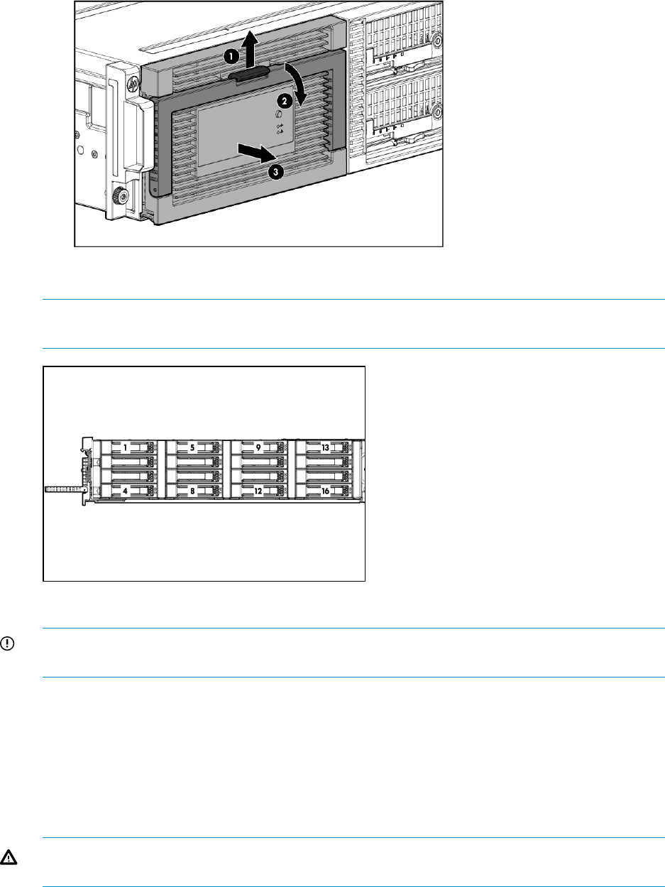
3. Extend the hard drive drawer (3).
5. Label the hard drives.
NOTE: Use the drive labels provided with the replacement midplane board when removing
the drives to ensure you replace the drives in the correct order.
6. Remove all hard drives.
IMPORTANT: Install the hard drives in the same slots from which you removed them or the
system might fail.
7. Push the drive drawer back into the messaging system enclosure.
8. Label each server blade, and then remove both server blades.
9. Label the cables connected to the back of the enclosure so they can be returned to their original
locations.
10. Unplug all cables from the back of the messaging system enclosure.
11. Unscrew the retaining screws from the bezel ears, and then remove the enclosure from the
rack.
WARNING! The messaging system enclosure is heavy, even after removing the hard drives.
Always use at least two people to remove the messaging system from the rack.
12. Remove the top back panel by pressing the panel release button and lifting the latch to slide
the top back panel off.
13. Remove all modules from the back of the enclosure.
78 Removing and replacing hardware components
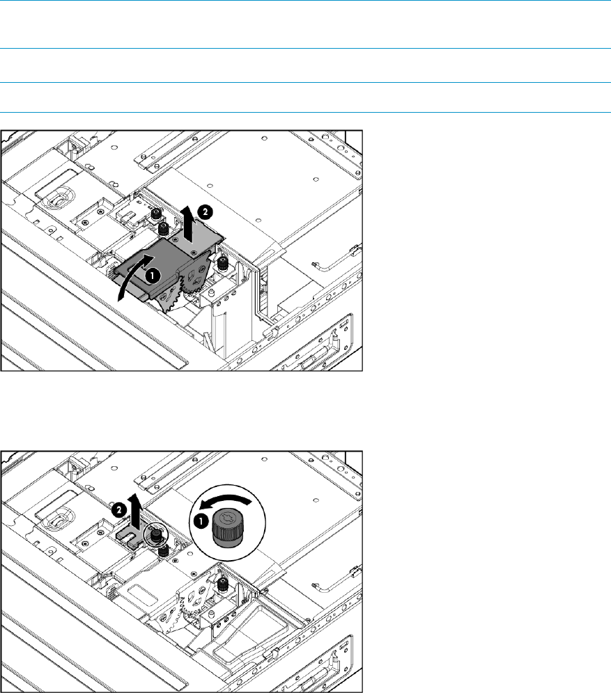
NOTE: Make a note of all module locations so they can be placed back into their original
locations.
14. Open the release handle (1), and pull up to remove the server interposer board (2).
NOTE: This step may require significant force to accomplish.
15. Pull the drawer handle down 90 degrees, and slide out the hard drive drawer.
16. Remove the plug bracket (2) from the coil power plug by removing the thumbscrew (1).
17. Unplug the coil power assembly from the midplane board.
Removing and replacing the midplane board 79

18. Extend the server blades.
19. Remove the server blade airflow baffle from inside the enclosure.
20. Unplug the power cable from the server blade midplane (1), and then unplug the rear UID
PCA from the midplane board (2).
80 Removing and replacing hardware components
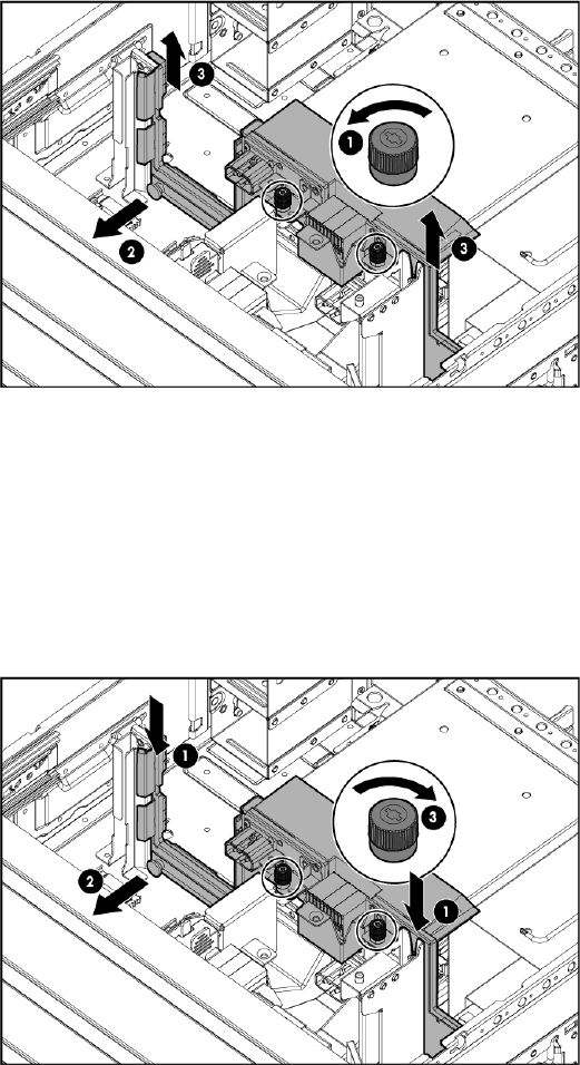
21. Loosen the two thumbscrews holding midplane board in place (1), pull the capacitive locking
pin out of the midplane board (2), and then lift the midplane board out of the enclosure (3).
Replacing the midplane board
To replace the midplane board:
1. Pull the capacitive locking pin out while inserting the midplane board.
2. Install the replacement midplane board by placing the midplane board in the enclosure (1),
push the capacitive locking pin into the midplane board (2), and then tighten the two
thumbscrews holding the midplane board in place (3).
3. Plug the rear UID PCA into the midplane board.
4. Plug the power cable into the server blade midplane.
5. Partially insert the drive drawer.
6. Plug the coil power plug into the midplane board.
7. Reattach the coil power plug bracket.
8. Reinsert the server blade airflow baffles.
9. Reinstall the server interposer board.
10. Push the hard drive drawer back into the enclosure.
11. Replace the top back panel.
12. Reinsert all rear components in the enclosure.
Removing and replacing the midplane board 81
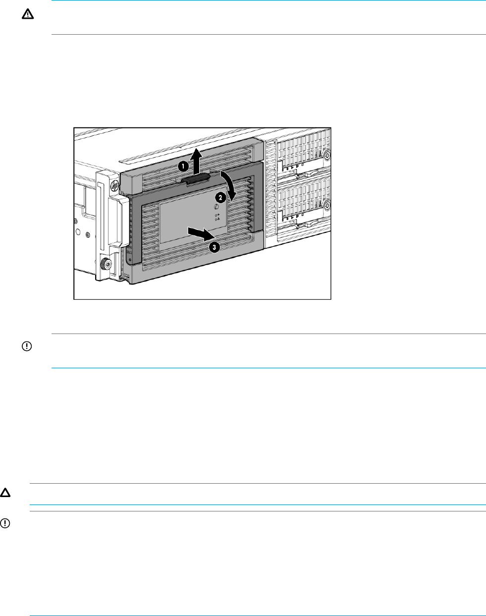
13. Place the enclosure into the rack, and then tighten the two retaining screws.
WARNING! The messaging system enclosure is heavy, even after removing the hard drives.
Always use at least two people to replace the messaging system in the rack.
14. Replace both server blades in their original bays.
15. Extend the hard drive drawer:
1. Press upward on the release button on the hard drive drawer (1).
2. Pull the drawer handle down 90 degrees (2).
3. Extend the hard drive drawer (3).
16. Replace all hard drives.
IMPORTANT: Install the hard drives in the same slots from which you removed them or the
system might fail. Use the drive labels to ensure they are replaced in the correct order.
17. Push the hard drive drawer back into the messaging system enclosure.
18. Plug in all cables at the back of the messaging system enclosure, and ensure that all cables
are returned to their original locations.
19. Power on the system by pressing the power button On.
20. Confirm the messaging system has resumed normal operations.
Removing and replacing a SAS cable
CAUTION: Remove only one cable at a time to prevent downtime.
IMPORTANT: Check the QuickSpecs for the device before you purchase and connect SAS cables
to ensure that the cables do not exceed the maximum supported length. Only specific cable lengths
were tested and approved for use with external expansion nodes.
IMPORTANT: Ensure that cabling in the back of the rack system does not interfere with system
operation or maintenance. Bind cables loosely with cable ties and route the excess out of the way,
along the side of the rack. When cables are tied together and routed down the side of the rack,
system components and indicators are easily visible and accessible.
Removing the SAS cable
To remove the SAS cable:
1. Verify the failed component by checking for a LED status on the failed component.
2. Remove the SAS cable that connects the messaging system SAS I/O module to the switch.
82 Removing and replacing hardware components
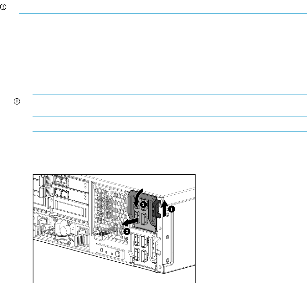
Replacing the SAS cable
To replace the SAS cable:
1. Connect the SAS cable between the messaging system SAS I/O module and the switch.
2. Verify that the replacement SAS cable is working properly by checking the associated LED
status.
3. Confirm that the messaging system has resumed normal operations.
Removing and replacing the SAS I/O module
IMPORTANT: Be sure to unpack the replacement part before you remove the existing component.
This section describes how to remove and replace the SAS I/O module in the messaging system.
Removing the SAS I/O module
To remove the SAS I/O module:
1. Use System Manager to identify the failed component.
2. Verify the failed component by checking for a the blinking amber LED on the failed component.
3. Label the cables so they can be returned to their original locations.
4. Unplug all cables from the SAS I/O module.
IMPORTANT: The SAS I/O cables must be installed in the same slots from which they are
removed or the system might fail.
5. Pull up on the SAS I/O Module release button.
NOTE: You may need to use significant force to accomplish this task.
6. Push down on the SAS I/O module lever (2), and then remove the failed SAS I/O module
(1), (3).
Replacing the SAS I/O module
To replace the SAS I/O module:
Removing and replacing the SAS I/O module 83
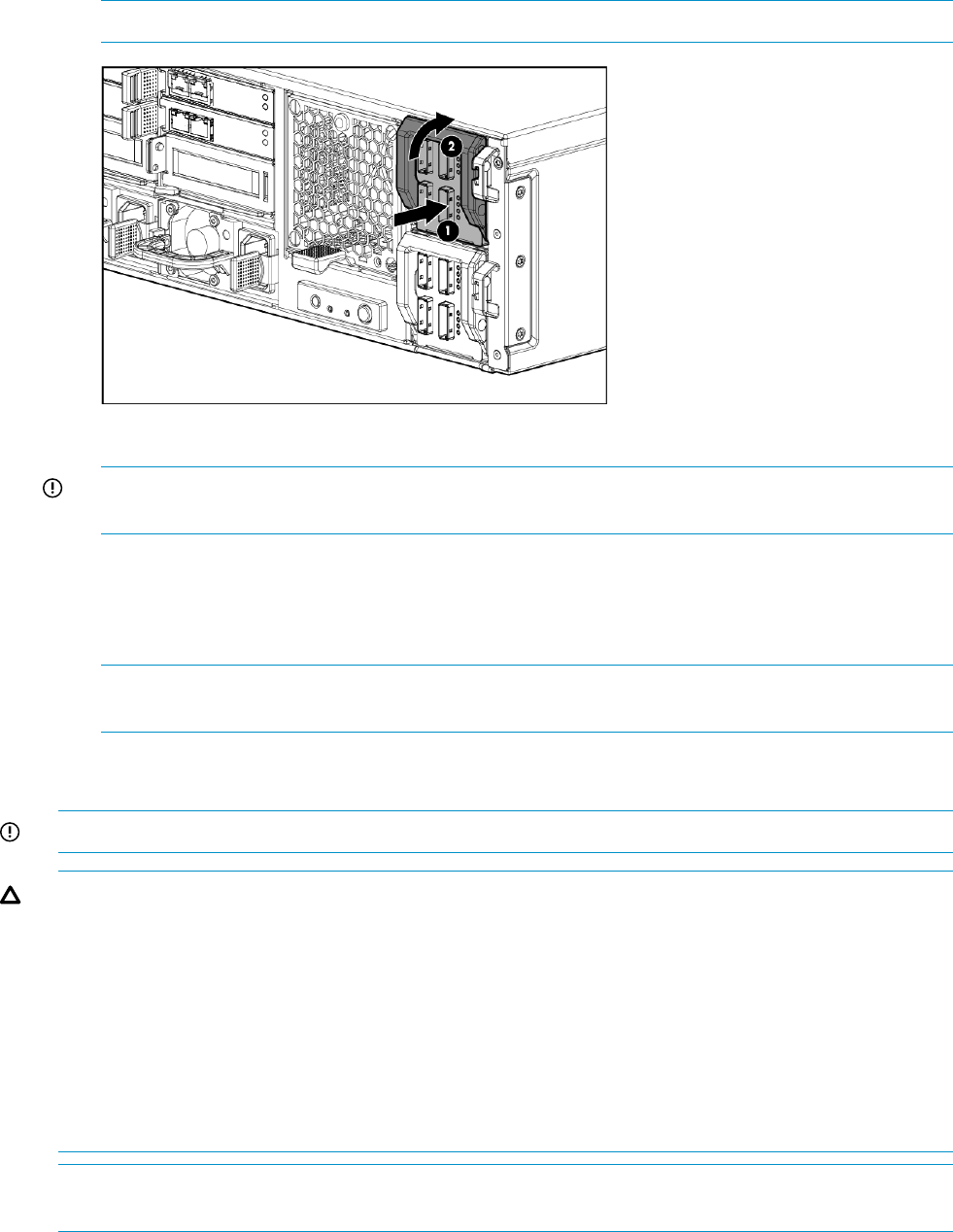
1. Insert the replacement SAS I/O module (1), and then push up on the SAS I/O module lever
(2) until it locks into place.
NOTE: You may need to use significant force to accomplish this task.
2. Plug in all cables to the SAS I/O module.
IMPORTANT: You must install the SAS I/O cables in the same slots from which they are
removed or the system might fail.
3. Verify that the replacement SAS I/O module is working properly by checking the associated
LED status.
4. Confirm the firmware version.
5. Confirm the system has resumed normal operations.
NOTE: The green LED should turn on within 5 seconds after the new module is inserted in
the system, which reflects the necessary time to boot the firmware.
Removing and replacing the drive fan module
IMPORTANT: Be sure to unpack the replacement part before you remove the existing component.
CAUTION: You must replace the server fan module within 3 minutes or you might lose data. The
total time allowance is 3 minutes for replacing the driver module, which includes the removal of
the original server fan module and installation of the replacement fan.
CAUTION: Removing a fan module significantly changes the air flow within the enclosure. Both
fan modules must be installed for the enclosure to cool properly. The fan modules are not redundant
to each other, and each module cools a different half of the enclosure. If a single fan module fails,
leave it in place in the enclosure until a new fan is available to install. The fan modules have some
built-in redundancy to keep operating until a replacement can be made. The remaining fan module
speeds up and allows operation for a limited time, based on operating and environmental
conditions. If a temperature threshold is exceeded, the enclosure automatically shuts down.
NOTE: There are two fan modules in the messaging system: one server fan module and one hard
drive fan module.
This section describes how to remove and replace the drive fan module in the messaging system.
84 Removing and replacing hardware components
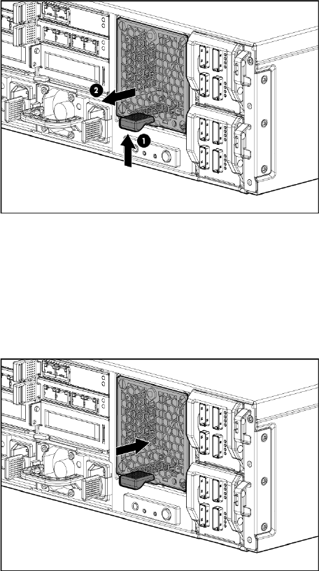
Removing the drive fan module
To remove the drive fan module:
1. Use System Manager to identify the failed component.
2. Verify the failed component by checking for a blinking amber LED on the failed component.
3. Press upward on the drive fan module release lever (1).
4. Remove the drive fan module (2).
Replacing the drive fan module
To replace the drive fan module:
1. Insert the replacement fan module.
2. Verify that the replacement component is working properly by checking the associated LED
status.
Removing and replacing the drive fan module 85
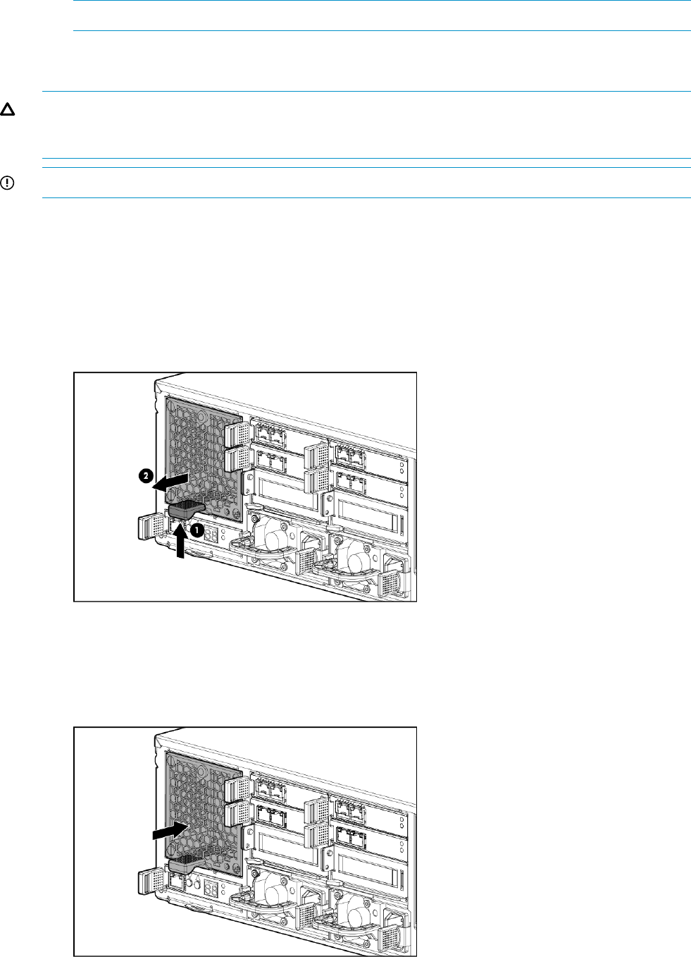
3. Confirm that the messaging system has resumed normal operations.
NOTE: It should take approximately 15 seconds for the LED status to appear.
Removing and replacing the server fan module
CAUTION: You must replace the server fan module within 3 minutes or you might lose data. The
total time allowance is 3 minutes for replacing the driver module, which includes the removal of
the original server fan module and installation of the replacement fan.
IMPORTANT: Be sure to unpack the replacement part before you remove the existing component.
This section describes how to remove and replace the server fan module in the messaging system.
Removing the server fan module
To remove the server fan module:
1. Use System Manager to identify the failed component.
2. Verify the failed component by checking for a blinking amber LED on the failed component.
3. Press the server fan module release lever up (1), and then remove the server fan module (2).
Replacing the server fan module
To replace the server fan module:
1. Insert the replacement fan module.
86 Removing and replacing hardware components
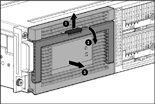
2. Verify that the replacement fan module is working properly by checking the associated LED
status.
3. Confirm that the messaging system has resumed normal operations.
Removing and replacing the power UID button assembly
This section describes how to remove and replace the power UID button assembly in the messaging
system.
Removing the power UID button assembly
To remove the power UID button assembly:
1. Power off the system:
1. Shut down blade 2 by clicking on Start and then Shut Down while you are connected to
blade 1.
2. Shut down blade 1 by clicking on Start and then Shut Down while you are connected to
blade 2.
3. Power off the expansion nodes, if present, by pressing and holding the power button at
the back.
4. Power off the storage solution by pressing and holding the power button at the back of
the enclosure.
5. Disconnect the power cables.
2. Extend the hard drive drawer:
1. Press upward on the release button on the hard drive drawer (1).
2. Pull the drawer handle down 90 degrees (2).
3. Extend the hard drive drawer (3).
3. Label the hard drives.
Removing and replacing the power UID button assembly 87
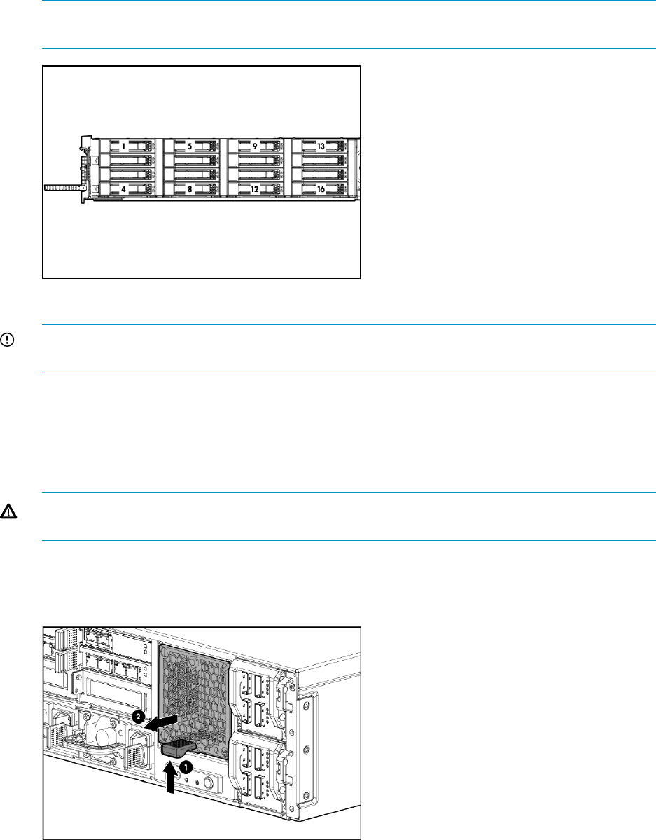
NOTE: Use the drive labels provided with the replacement rear power UID button assembly
when removing the drives to ensure you replace the drives in the correct order.
4. Remove all hard drives.
IMPORTANT: Install the hard drives in the same slots from which you removed them or the
system might fail.
5. Push the drive drawer back into the messaging system enclosure.
6. Label each blade and then remove both server blades.
7. Label the cables and then unplug all cables from the back of the messaging system enclosure.
8. Unscrew the retaining screws from the bezel ears, and then remove the enclosure from the
rack.
WARNING! The messaging system enclosure is heavy, even after removing the hard drives.
Always use at least two people to remove the messaging system from the rack.
9. Remove the top back panel by pressing the panel release button and lifting the latch to slide
the top back panel off.
10. Remove the hard drive fan module.
88 Removing and replacing hardware components
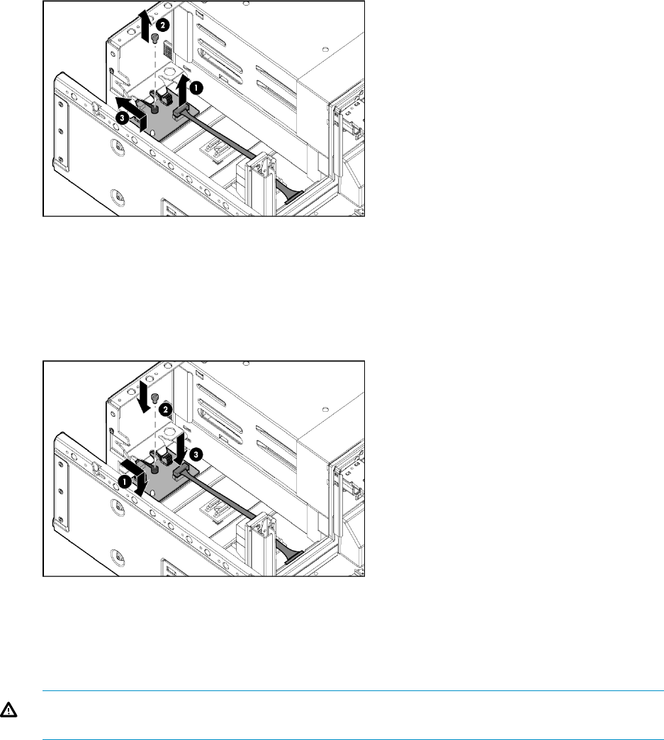
11. Unplug the cable from the power UID button assembly (1) and remove the screw from the
power UID button assembly (2). Then remove the faulty power UID button assembly (3).
Replacing the power UID button assembly
To replace the power UID button assembly:
1. Install the replacement power UID button assembly (1) and replace the screw in the power
UID button assembly (2). Then plug the cable into the power UID button assembly (3).
2. Push the hard drive drawer back in the messaging system enclosure.
3. Replace the hard drive fan module.
4. Replace the top back panel.
5. Place the messaging system into the rack and tighten the two retaining screws.
WARNING! The messaging system enclosure is heavy, even after removing the hard drives.
Always use at least two people to replace the messaging system in the rack.
6. Replace the server blades in their original bays.
7. Extend the hard drive drawer:
1. Press upward on the release button on the hard drive drawer (1).
2. Pull the drawer handle down 90 degrees (2).
Removing and replacing the power UID button assembly 89

3. Extend the hard drive drawer (3).
8. Replace all hard drives.
IMPORTANT: Install the hard drives in the same slots from which you removed them or the
system might fail. Use the drive labels to ensure they are replaced in the correct order.
9. Push the drive drawer back into the messaging system enclosure.
10. Plug in all cables at the back of the messaging system enclosure into their original locations.
11. Power on the messaging system.
12. Confirm that the messaging system has resumed normal operations.
Removing and replacing the power supply
This section describes how to remove and replace the power supply in the messaging system.
Removing the power supply
To remove the power supply:
1. Use System Manager to identify the failed component.
2. Verify the failed component by checking for a blinking amber LED on the failed component.
3. Remove the power cord from the power supply.
4. Press the power supply release lever to the left.
5. Remove the failed power supply.
Replacing the power supply
To replace the power supply:
1. Insert the replacement power supply.
2. Plug the power cord into the power supply.
3. Verify that the replacement component is working properly by checking the associated LED
status.
4. Confirm that the messaging system has resumed normal operations.
Removing and replacing the HP StorageWorks Ethernet I/O module
IMPORTANT: Be sure to unpack the replacement part before you remove the existing component.
This section describes how to remove and replace the HP StorageWorks Ethernet I/O module in
the network or Mezz slots of the system enclosure.
90 Removing and replacing hardware components

Removing the HP StorageWorks Ethernet I/O module
To remove the HP StorgeWorks Ethernet I/O module in the network or Mezz slots of the system
enclosure:
1. Use System Manager to identify the failed component.
2. Verify the failed component by checking for a blinking amber LED on the failed component.
3. Label the cables, and then unplug all cables from the HP StorageWorks Ethernet I/O module.
4. Press the module release mechanism to the right (1), and then remove the failed module (2).
Replacing the HP StorageWorks Ethernet I/O module
To replace the HP StorgeWorks Ethernet I/O module in the network or Mezz slots of the system
enclosure:
1. Insert the replacement HP StorageWorks Ethernet I/O module.
2. Plug in all cables to the replacement module to their original locations.
3. Verify that the replacement component is working properly by checking the associated LED
status.
4. Confirm the firmware version.
Removing and replacing the HP StorageWorks Ethernet I/O module 91
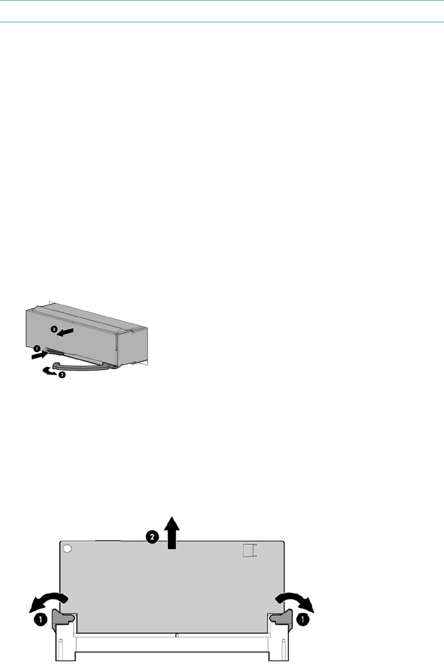
5. Confirm that the messaging system has resumed normal operations.
NOTE: It should take approximately 15 seconds for the LED status to display.
Removing and replacing the Mezzanine NIC
Removing the Mezzanine NIC
Optional Mezzanine cards enable network connectivity or provide Fibre Channel support.
The Mezzanine NIC might have captive screws that are required to secure it to the server blade.
When installing a Mezzanine NIC in this server blade, only two captive screws are required.
To remove the Mezzanine NIC:
1. Back up all data.
2. Close all applications.
3. Power off the server blade by pressing and releasing the blade power button. Verify the server
blade is shut down before continuing.
4. Power off the external expansion nodes by pressing and holding the power button at the back,
and then power off the enclosure by pressing and holding the power button at the back of
the enclosure.
5. Push the button to release the handle (1), pull the handle toward you (2), and then remove
the server blade from the enclosure (3).
6. Press the release button on the access panel and slide the access panel to the left to remove
the access panel. The Mezzanine NIC is under the controller card.
7. Since the original cache module is connected to a capacitor pack, observe the cache module
LEDs ()Figure 14 (page 55).
•If the amber LED is solid, data transfer to the flash device on the cache module is in
progress. Do not remove the cache module until the amber LED is off, and then continue
with the next step.
•If the amber LED is not lit, proceed to the next step.
92 Removing and replacing hardware components
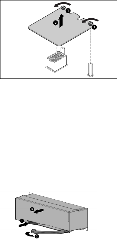
8. Open the ejector latches (1) on each side of the cache module slot.
Typically, opening the ejector latches ejects the cache module automatically. If the module
does not eject automatically after you open the ejector latches, remove the cache module (2)
by grasping only the edges.
9. Remove the cache module and the capacitor from the blade.
10. The Mezzanine NIC is underneath the controller card. Remove the controller card by loosening
the captive screws (1), and then remove the Mezzanine NIC (2).
1. Back up all data.
2. Close all applications.
3. Power off the server blade by pressing and releasing the blade power button. Verify the server
blade is shut down before continuing.
4. Power off the external expansion nodes by pressing and holding the power button at the back,
and then power off the enclosure by pressing and holding the power button at the back of
the enclosure.
5. Push the button to release the handle (1), pull the handle toward you (2), and then remove
the server blade from the enclosure (3).
6. Press the release button on the access panel and slide the access panel to the left to remove
the access panel. The Mezzanine NIC is under the controller card.
7. Since the original cache module is connected to a capacitor pack, observe the cache module
LEDs ()Figure 14 (page 55).
•If the amber LED is solid, data transfer to the flash device on the cache module is in
progress. Do not remove the cache module until the amber LED is off, and then continue
with the next step.
Removing and replacing the Mezzanine NIC 93

•If the amber LED is not lit, proceed to the next step.
8. Open the ejector latches (1) on each side of the cache module slot.
Typically, opening the ejector latches ejects the cache module automatically. If the module
does not eject automatically after you open the ejector latches, remove the cache module (2)
by grasping only the edges.
9. Remove the cache module and the capacitor from the blade.
10. The Mezzanine NIC is underneath the controller card. Remove the controller card by loosening
the captive screws (1), and then remove the Mezzanine NIC (2).
Replacing the Mezzanine NIC
To replace the Mezzanine NIC:
1. Install the Mezzanine NIC , press down on the connector to seat the board (1), and then
tighten the captive screws (2).
2. Reinstall the controller card, and then Install the access panel.
3. Install the server blade in the enclosure.
94 Removing and replacing hardware components
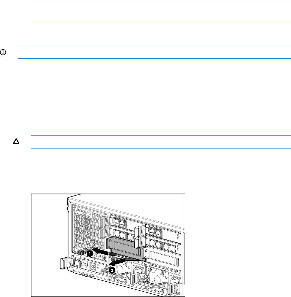
4. Confirm the firmware version.
NOTE: You must reboot the storage solution after updating Mezzanine NIC and server blade
firmware.
Removing and replacing the PCIe module (with card)
IMPORTANT: Be sure to unpack the replacement part before you remove the existing component.
This section describes how to remove and replace the PCIe module (with card) in the messaging
system.
Removing the PCIe module
To remove the PCIe module:
1. Use System Manager to identify the failed component.
2. Verify the failed component by checking for a blinking amber LED on the failed component.
3. Power off the appropriate server blade associated with the PCIe module that is being removed.
CAUTION: Be sure to power off the server before removing the PCIe module.
4. Label the cables so they can be returned to their original locations.
5. Unplug all cables from the PCIe module.
6. Press the PCIe module release mechanism to release the handle (1), and then pull the handle
to remove the PCIe module from the system (2).
Removing and replacing the PCIe module (with card) 95
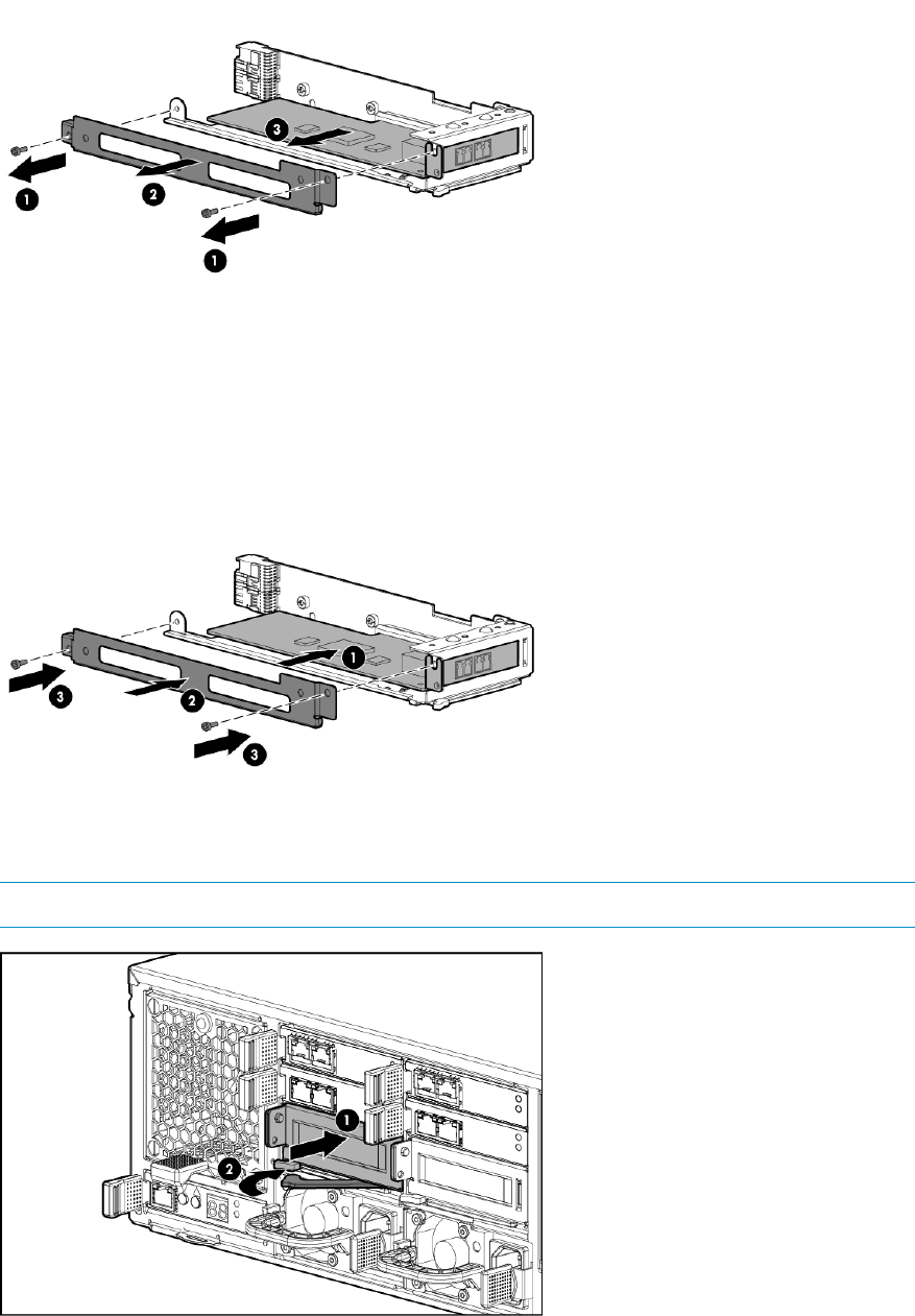
7. Remove the two screws from the bracket of the failed PCIe module (1), remove the bracket
(2), and then remove the PCIe card from the failed module (3).
Replacing the PCIe module
To replace the PCIe module:
1. Install the PCIe card in the replacement module (1), replace the bracket (2), and then reinsert
the two screws into the bracket of the replacement module (3).
2. Insert the replacement PCIe module into the system (1), and lock the release lever (2).
NOTE: The PCIe module should be inserted with the lever in the open position.
3. Plug in all cables to the PCIe module in their original locations.
4. Power on the server blade by pressing the power button On.
96 Removing and replacing hardware components
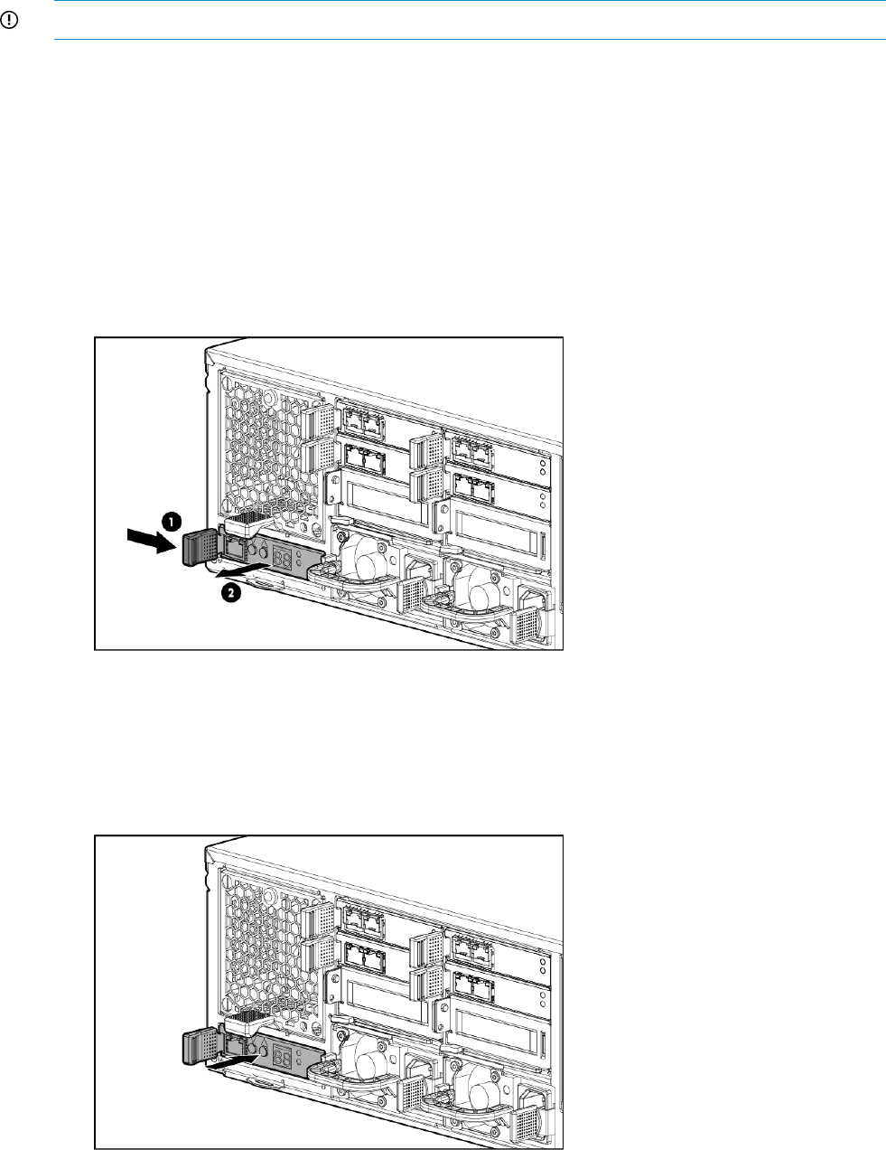
5. Verify that the replacement component is working properly by checking the associated LED
status.
6. Confirm the system has resumed normal operations.
Removing and replacing the Enclosure Manager Unit
IMPORTANT: Be sure to unpack the replacement part before you remove the existing component.
This section describes how to remove and replace the Enclosure Manager Unit in the messaging
system.
Removing the Enclosure Manager Unit module
To remove the Enclosure Manager Unit module:
1. Use System Manager to identify the failed component.
2. Verify the failed component by checking for a blinking amber LED on the failed component.
3. Unplug any cables from the Enclosure Manager Unit module.
4. Press the Enclosure Manager Unit module release lever to the right (1), and then remove the
Enclosure Manager Unit module (2).
Replacing the Enclosure Manager Unit module
To replace the Enclosure Manager Unit module:
1. Insert the replacement Enclosure Manager Unit module and ensure the release lever locks in
place for module installation.
Removing and replacing the Enclosure Manager Unit 97

2. Plug the cables back into the Enclosure Manager Unit module.
3. Verify that the new component is working properly by checking the associated LED status.
4. Confirm the firmware version.
5. Obtain an IP address.
IMPORTANT: Some of the configuration information is automatically repopulated, but you
must reconfigure the network settings and password.
6. Confirm the system has resumed normal operations.
NOTE: This may take approximately 1 minute, or the time it takes for the Enclosure Manager
to boot.
Removing and replacing the server blade backplane
This section describes how to remove and replace the server blade backplane in the messaging
system.
Removing the server blade backplane
To remove the server blade backplane:
1. Use System Manager to identify the failed component.
2. Power off the system:
1. Shut down blade 2 by clicking on Start and then Shut Down while you are connected to
blade 1.
2. Shut down blade 1 by clicking on Start and then Shut Down while you are connected to
blade 2.
3. Power off the expansion nodes, if present, by pressing and holding the power button at
the back.
4. Power off the storage solution by pressing and holding the power button at the back of
the enclosure.
5. Disconnect the power cables.
3. Extend the hard drive drawer:
1. Press upward on the release button on the hard drive drawer (1).
2. Pull the drawer handle down 90 degrees (2).
3. Extend the hard drive drawer (3).
4. Label the hard drives.
98 Removing and replacing hardware components

NOTE: Use the drive labels provided with the replacement server blade backplane when
removing the drives to ensure you replace the drives in the correct order.
5. Remove all hard drives.
IMPORTANT: Install the hard drives in the same slots from which you removed them or the
system might fail.
6. Push the drive drawer back into messaging system enclosure.
7. Label each server blade, and then remove both server blades.
8. Label the cables on the back of the messaging system enclosure so they can be returned to
their original locations.
9. Unplug all cables from the back of the messaging system enclosure.
10. Unscrew the retaining screws from the bezel ears and then remove the enclosure from the
rack.
WARNING! The messaging system enclosure is heavy, even after removing the hard drives.
Always use at least two people to remove the messaging system from the rack.
11. Remove the top back panel by pressing the panel release button and lifting the latch to slide
the top back panel off.
12. Remove all modules from the back of the enclosure.
13. Open the release handle (1), and pull up to remove the server interposer board (2).
NOTE: This step may require significant force to accomplish.
Removing and replacing the server blade backplane 99
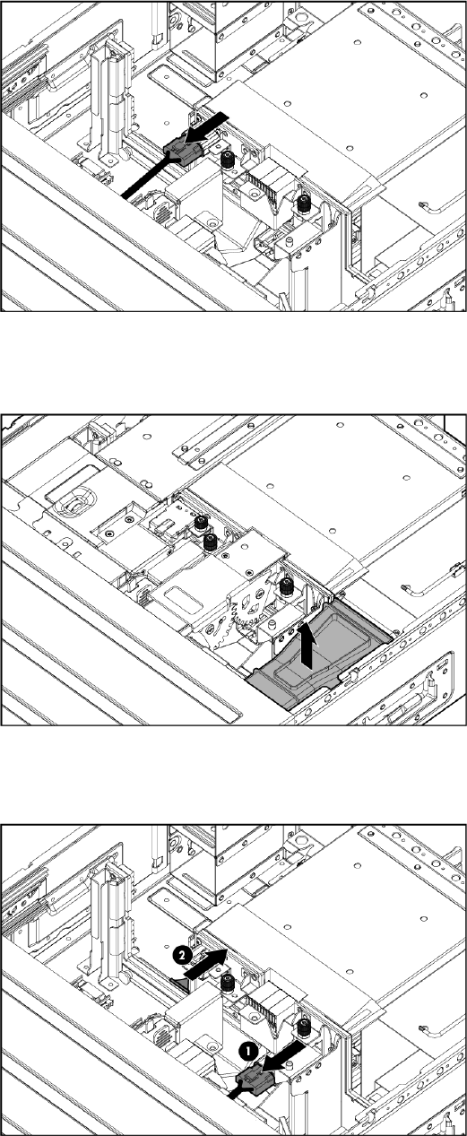
14. Pull the drawer handle down 90 degrees, and slide out the hard driver drawer.
15. Remove the plug bracket (2) from the coil power plug by removing the thumbscrew (1).
16. Unplug the coil power assembly from the midplane board.
17. Extend the server blades.
18. Remove the server blade airflow baffle from inside the enclosure.
19. Unplug the power cable from the server blade midplane (1), and then unplug the rear UID
PCA from the midplane board (2).
100 Removing and replacing hardware components
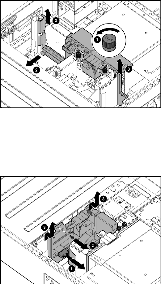
20. Loosen the two thumbscrews holding the midplane board in place (1), pull the capacitive
locking pin out of the midplane board (2), and then lift the midplane board out of the enclosure
(3).
21. Remove the small baffle from beside the server blade backplane by pinching the tabs and
lifting the small baffle out of the enclosure.
22. Remove the large baffle from the bottom of the enclosure.
23. Unplug the power cable from the server backplane by pinching the plug release mechanism
(1), remove the screw (2), and then remove the server blade backplane from the enclosure
(3).
Replacing the server blade backplane
To replace the server blade backplane:
Removing and replacing the server blade backplane 101

1. Install the replacement server blade backplane (1), replace the screw (2), and then plug in
the power cable (3).
2. Replace the large baffle on the bottom of the enclosure.
3. Replace the small baffle beside the server blade backplane.
4. Pull the capacitive locking pin out while inserting the midplane board.
5. Install the replacement midplane board by placing the midplane board enclosure (1), push
the capacitive locking pin into the midplane board (2), and then tighten the two thumbscrews
holding the midplane board in place (3).
6. Plug the rear UID PCA into the midplane board.
7. Plug the power cable into the server blade backplane.
8. Partially insert the drive drawer.
9. Plug the coil power plug into the midplane board.
10. Reattach the coil power plug bracket.
11. Reinsert the server blade airflow baffles.
12. Reinstall the server interposer board.
13. Push the drive drawer back into the enclosure.
14. Replace the top back panel.
15. Reinsert all rear components.
102 Removing and replacing hardware components

16. Place the enclosure into the rack, and then secure the enclosure by tightening the two retaining
screws.
WARNING! The messaging system enclosure is heavy, even after removing the hard drives.
Always use at least two people to replace the messaging system from the rack.
17. Replace both server blades in their original bays.
18. Extend the hard drive drawer:
1. Press upward on the release button on the hard drive drawer (1).
2. Pull the drawer handle down 90 degrees (2).
3. Extend the hard drive drawer (3).
19. Replace all hard drives.
IMPORTANT: Install the hard drives in the same slots from which you removed them or the
system might fail. Use the drive labels to ensure they are replaced in the correct order.
20. Push the drive drawer back into the messaging system enclosure.
21. Plug in all cables at the back of the messaging system enclosure, and ensure that all cables
are returned to their original locations.
22. Power on the system by pressing the power button On.
23. Confirm the messaging system has resumed normal operations.
Removing and replacing the server airflow baffle
IMPORTANT: Be sure to unpack the replacement part before you remove the existing component.
This section describes how to remove and replace the server airflow baffle in the messaging system.
Removing the server airflow baffle
To remove the server airflow baffle:
Removing and replacing the server airflow baffle 103

1. Power off the system:
1. Shut down blade 2 by clicking on Start and then Shut Down while you are connected to
blade 1.
2. Shut down blade 1 by clicking on Start and then Shut Down while you are connected to
blade 2.
3. Power off the expansion nodes, if present, by pressing and holding the power button at
the back.
4. Power off the storage solution by pressing and holding the power button at the back of
the enclosure.
5. Disconnect the power cables.
2. Extend the hard drive drawer:
1. Press upward on the release button on the hard drive drawer (1).
2. Pull the drawer handle down 90 degrees (2).
3. Extend the hard drive drawer (3).
3. Label the hard drives.
NOTE: Use the drive labels provided with the replacement server airflow baffle when
removing the drives to ensure you replace the drives in the correct order.
4. Remove all hard drives.
IMPORTANT: Install the hard drives in the same slots from which you removed them or the
system might fail.
5. Push the drive drawer back into the messaging system enclosure.
104 Removing and replacing hardware components
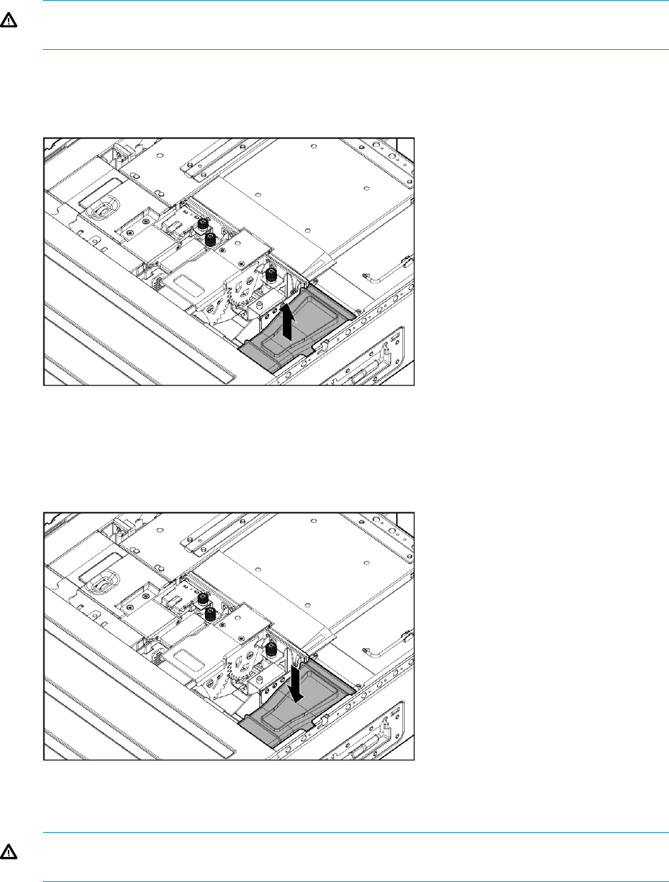
6. Label each server blade, and then remove both server blades.
7. Label and then unplug all cables from the back of the messaging system enclosure.
8. Unscrew the retaining screws from the bezel ears, and then remove the enclosure from the
rack.
WARNING! The messaging system enclosure is heavy, even after removing the hard drives.
Always use at least two people to remove the messaging system from the rack.
9. Remove the top back panel by pressing the release button and lifting the latch to slide the top
back panel off.
10. Remove the server blade airflow baffle from inside the enclosure.
Replacing the server airflow baffle
To replace the server airflow baffle:
1. Install the replacement server blade airflow baffle.
2. Reinstall the top back panel.
3. Place the enclosure back in the rack, and tighten the two retaining screws.
WARNING! The messaging system enclosure is heavy, even after removing the hard drives.
Always use at least two people to replace the messaging system in the rack.
4. Replace the server blades into their original bays.
5. Extend the hard drive drawer:
Removing and replacing the server airflow baffle 105
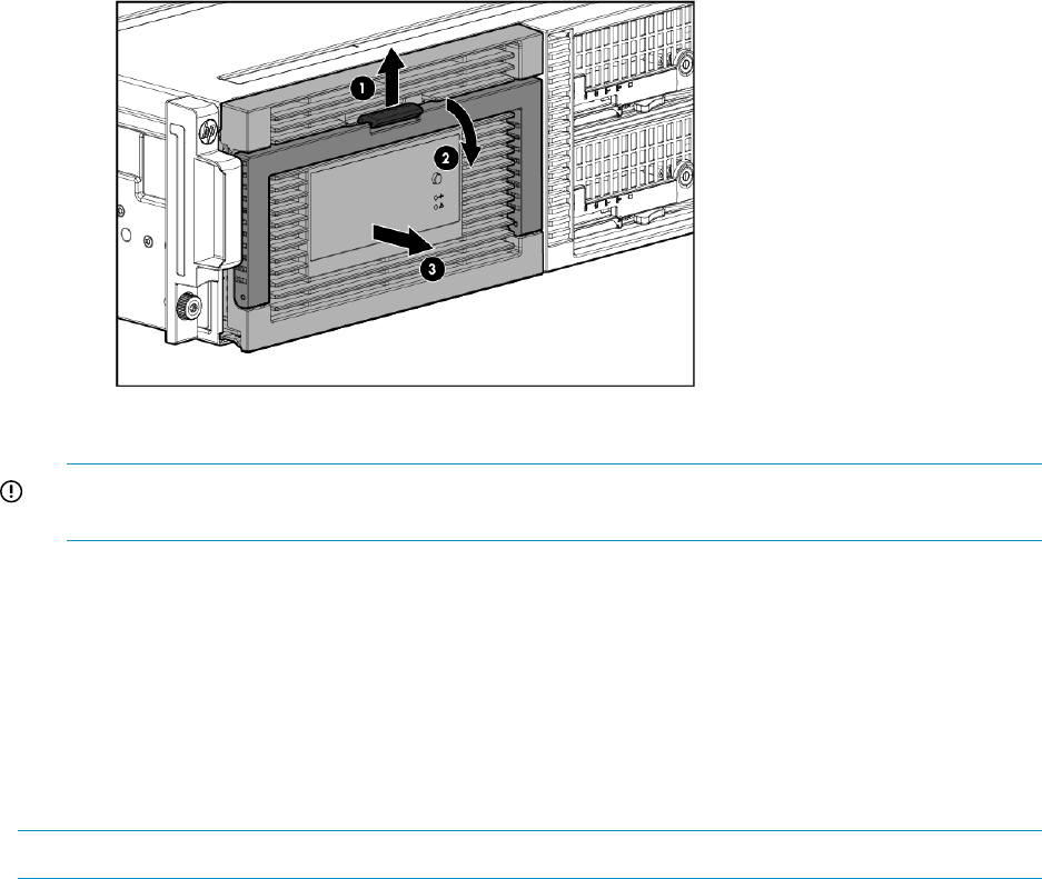
1. Press upward on the release button on the hard drive drawer (1).
2. Pull the drawer handle down 90 degrees (2).
3. Extend the hard drive drawer (3).
6. Replace all hard drives.
IMPORTANT: Install the hard drives in the same slots from which you removed them or the
system might fail. Use the drive labels to ensure they are replaced in the correct order.
7. Push the drive drawer back into the messaging system enclosure.
8. Plug in all cables at the back of the messaging system enclosure, and ensure that all cables
are returned to their original locations.
9. Power on the messaging system.
10. Confirm the messaging system has resumed normal operations.
Removing and replacing the front bezel (standard)
This section describes how to remove and replace the front bezel in the messaging system.
NOTE: Use the full procedure if you are not able to reach all of the screws due to rack positioning.
Removing the front bezel
To remove the front bezel in the rack:
1. Power off the system:
1. Shut down blade 2 by clicking on Start and then Shut Down while you are connected to
blade 1.
2. Shut down blade 1 by clicking on Start and then Shut Down while you are connected to
blade 2.
3. Power off the expansion nodes, if present, by pressing and holding the power button at
the back.
4. Power off the storage solution by pressing and holding the power button at the back of
the enclosure.
5. Disconnect the power cables.
2. Unplug all cables from back of the messaging system.
3. Extend the hard drive drawer:
1. Press upward on the release button on the hard drive drawer (1).
2. Pull the drawer handle down 90 degrees (2).
106 Removing and replacing hardware components

3. Extend the hard drive drawer (3).
4. Remove all eight screws from the front bezel (1), and then lift the front bezel up and out to
remove the front bezel (2).
NOTE: There are two screws on the bottom, four screws on the sides (two on each side),
and two screws hidden behind the handle.
Replacing the front bezel
To replace the front bezel in the rack:
Removing and replacing the front bezel (standard) 107
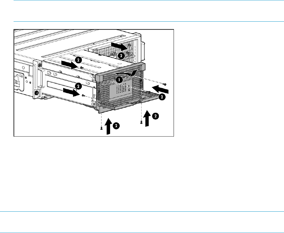
1. Install the replacement front bezel with the handle at a 90 degree angle making sure the
bottom pins are aligned with the bottom holes (1), and replace the screws into the front bezel
(2).
NOTE: There are two screws on the bottom, four screws on the sides (two on each side),
and two screws hidden behind the handle.
2. Push the drive drawer back into the messaging system enclosure.
3. Power on the messaging system.
4. Verify that the replacement component is working properly by checking the associated LED
status.
5. Confirm the system has resumed normal operations.
Removing and replacing the front bezel (full)
NOTE: This full procedure is only required if all screws are not accessible due to the position of
the messaging system in the rack.
This section describes how to fully remove and replace the front bezel in the messaging system.
Removing the front bezel (full)
To remove the front bezel:
1. To power off the system:
1. Shut down blade 2 by clicking on Start and then Shut Down while you are connected to
blade 1.
2. Shut down blade 1 by clicking on Start and then Shut Down while you are connected to
blade 2.
3. Power off the expansion nodes, if present, by pressing and holding the power button at
the back.
4. Power off the storage solution by pressing and holding the power button at the back of
the enclosure.
5. Disconnect the power cables.
2. Extend the hard drive drawer:
1. Press upward on the release button on the hard drive drawer (1).
2. Pull the drawer handle down 90 degrees (2).
108 Removing and replacing hardware components
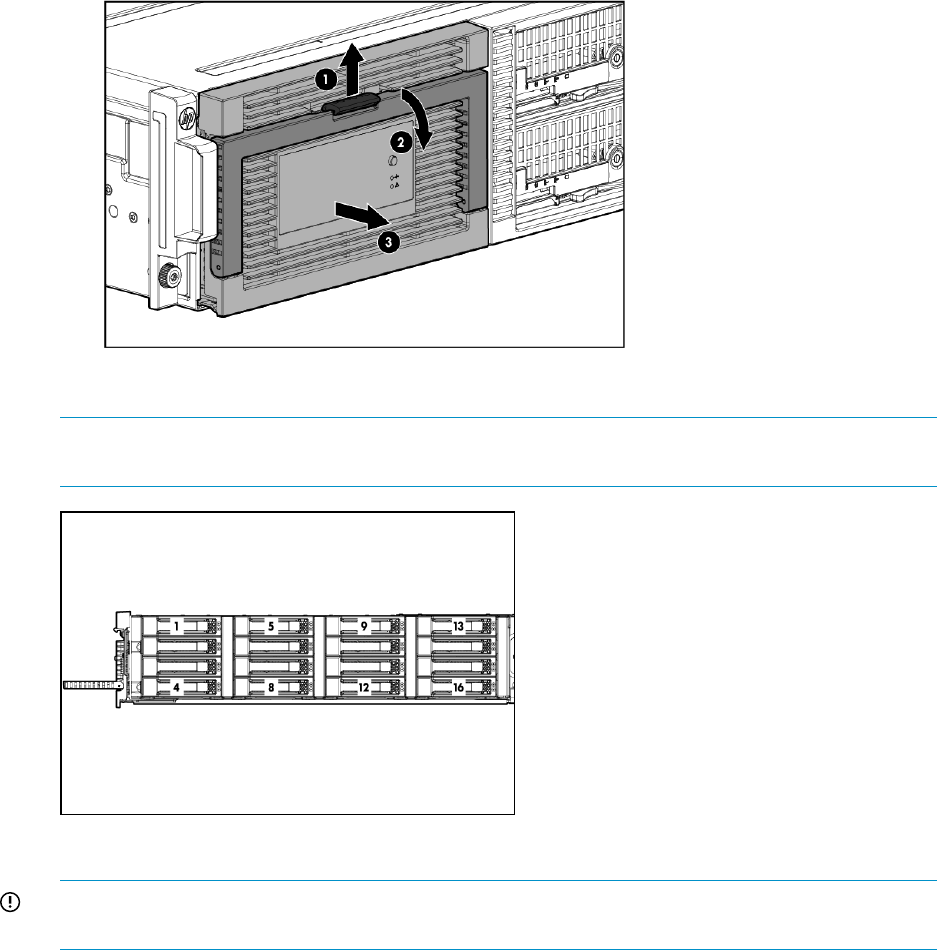
3. Extend the hard drive drawer (3).
3. Label the hard drives.
NOTE: Use the drive labels provided with the replacement front bezel (full) to label the hard
drives to ensure you replace the drives in the correct order.
4. Remove all hard drives.
IMPORTANT: Install the hard drives in the same slots from which you removed them or the
system might fail.
5. Push the drive drawer back into the messaging system enclosure.
6. Label each server blade and then remove both server blades.
7. Unplug all cables from the back of the messaging system enclosure.
Removing and replacing the front bezel (full) 109
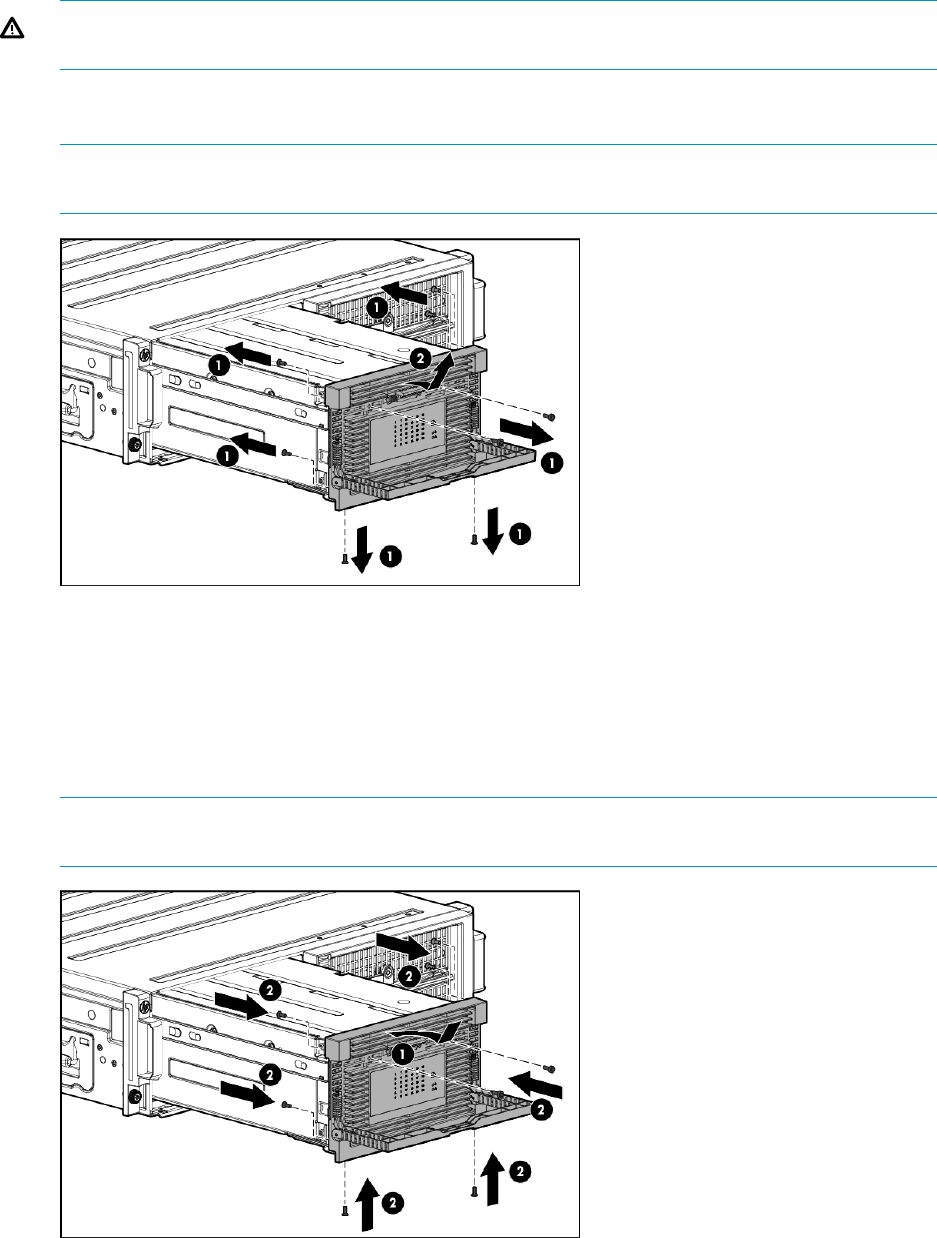
8. Remove the enclosure from the rack.
WARNING! The messaging system enclosure is heavy, even after removing the hard drives.
Always use at least two people to remove the messaging system from the rack.
9. Remove all eight screws from the front bezel and pull the handle down 90 degrees (1). Then
lift the front bezel up and out to remove the front bezel (2).
NOTE: There are two screws on the bottom, four screws on the sides (two on each side),
and two screws hidden behind the handle.
Replacing the front bezel (full)
To replace the front bezel:
1. Install the replacement front bezel with the handle at a 90 degree angle, making sure the
bottom pins are aligned with the bottom holes (1), and replace the screws in the front bezel
(2).
NOTE: There are two screws on the bottom, four screws on the sides (two on each side),
and two screws hidden behind the handle.
2. Close the drive handle.
3. Push the drive drawer back into the messaging system enclosure.
110 Removing and replacing hardware components
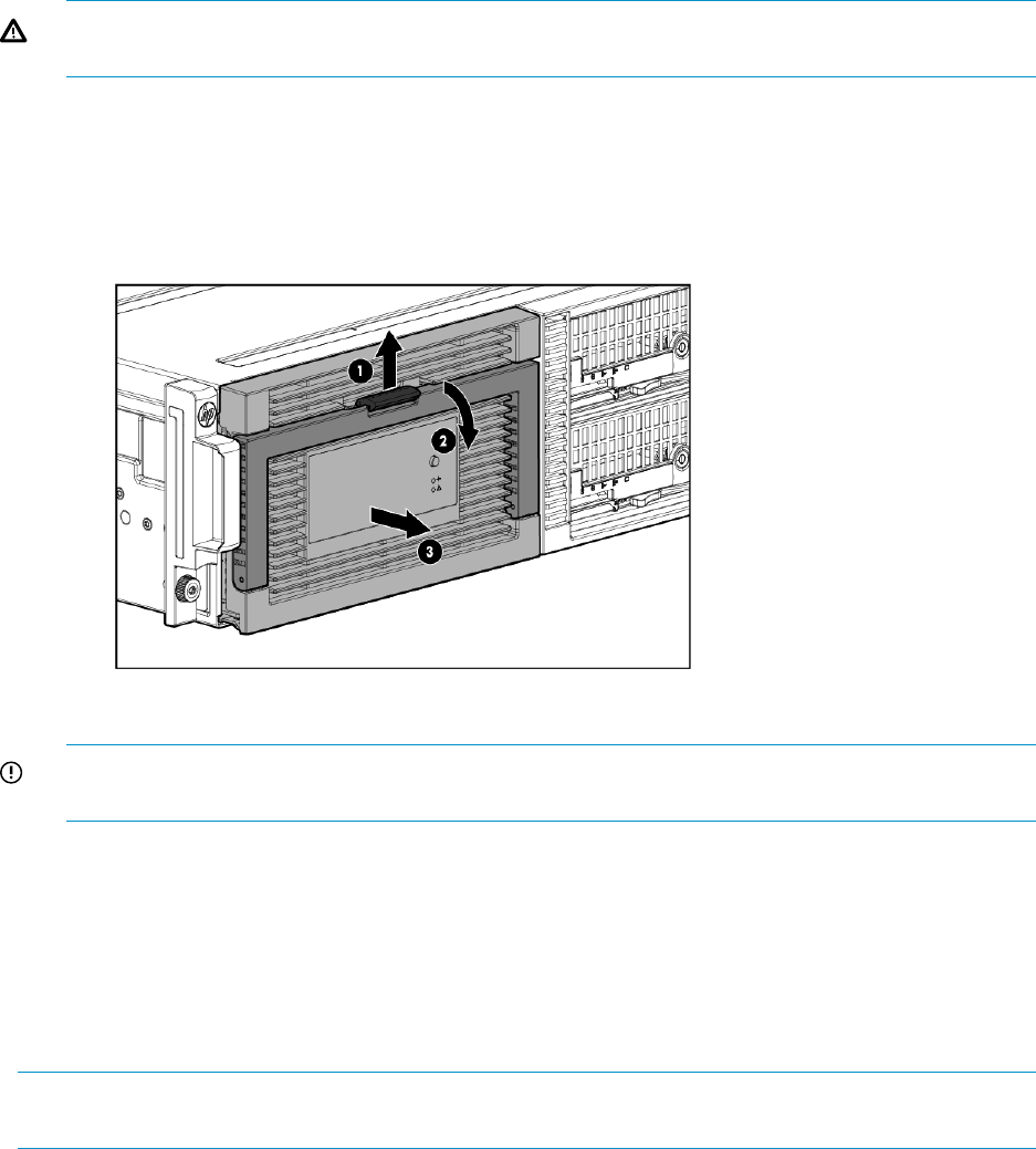
4. Place the enclosure into the rack.
WARNING! The messaging system enclosure is heavy, even after removing the hard drives.
Always use at least two people to replace the messaging system in the rack.
5. Replace the server blades.
6. Extend the hard drive drawer:
1. Press upward on the release button on the hard drive drawer (1).
2. Pull the drawer handle down 90 degrees (2).
3. Extend the hard drive drawer (3).
7. Replace all hard drives.
IMPORTANT: Install the hard drives in the same slots from which you removed them or the
system might fail. Use the drive labels to ensure you replace the drives in the correct order.
8. Push the drive drawer back into the messaging system enclosure.
9. Plug the cables into the back of the messaging system enclosure, ensuring that all cables are
returned to their original locations.
10. Power on the messaging system.
11. Confirm the messaging system has resumed normal operations.
Removing and replacing the front LED display board in the rack (standard)
NOTE: If you are not able to access all of the screws due to the enclosure position in the rack,
use the full procedure instructions.
This section describes how to remove and replace the front LED display board in the rack on the
messaging system.
Removing the front LED display board in the rack
To remove the front LED display board in the rack:
1. Use System Manager to identify the failed component.
2. Verify the failed component by checking for a blinking amber LED on the failed component.
3. Power off the system:
1. Shut down blade 2 by clicking on Start and then Shut Down while you are connected to
blade 1.
Removing and replacing the front LED display board in the rack (standard) 111
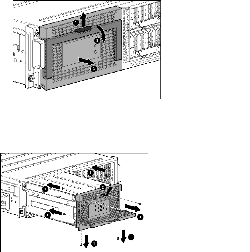
2. Shut down blade 1 by clicking on Start and then Shut Down while you are connected to
blade 2.
3. Power off the expansion nodes, if present, by pressing and holding the power button at
the back.
4. Power off the storage solution by pressing and holding the power button at the back of
the enclosure.
5. Disconnect the power cables.
4. Extend the hard drive drawer:
1. Press upward on the release button on the hard drive drawer (1).
2. Pull the drawer handle down 90 degrees (2).
3. Extend the hard drive drawer (3).
5. Remove all eight screws from the front bezel (1). Then lift the front bezel up and out to remove
the front bezel (2).
NOTE: There are two screws on the bottom, four screws on the sides (two on each side),
and two screws hidden behind the handle.
112 Removing and replacing hardware components
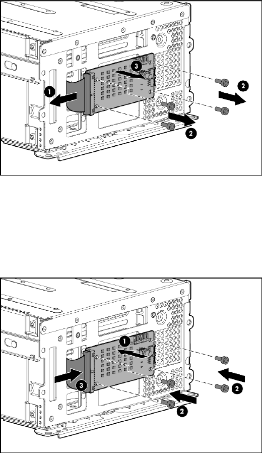
6. Disconnect the LED display board from the drive backplane by pinching the ends of the LED
display board together (1). Remove the four screws from the LED display board (2). Then,
remove the LED display board from the drive drawer (3).
Replacing the front LED display board in the rack
To replace the front LED display board in the rack on the messaging system:
1. Install the replacement LED display board (1), replace the four LED display board screws (2),
and then reconnect the LED display board to the drive drawer (3).
2. Replace the front bezel with the handle at a 90 degree angle, making sure the bottom pins
are aligned with the bottom holes (1). Then, replace the front bezel screws (2).
Removing and replacing the front LED display board in the rack (standard) 113
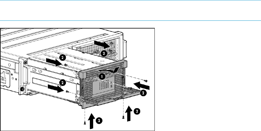
NOTE: There are two screws on the bottom, four screws on the sides (two on each side),
and two screws hidden behind the handle.
3. Close the drive handle.
4. Push the drive drawer back into the messaging system enclosure.
5. Power on the messaging system by pressing the power button On.
6. Verify that the replacement component is working properly by checking the associated LED
status.
7. Confirm that the messaging system has resumed normal operations.
Removing and replacing the front LED display board (full)
This section describes how to remove and replace the front LED display board (full) in the messaging
system.
Removing the front LED display board (full)
To remove the front LED display board (full):
1. Use System Manager to identify the failed component.
2. Verify the failed component by checking for a blinking amber LED on the failed component.
3. Power off the system:
1. Shut down blade 2 by clicking on Start and then Shut Down while you are connected to
blade 1.
2. Shut down blade 1 by clicking on Start and then Shut Down while you are connected to
blade 2.
3. Power off the expansion nodes, if present, by pressing and holding the power button at
the back.
4. Power off the storage solution by pressing and holding the power button at the back of
the enclosure.
5. Disconnect the power cables.
4. Extend the hard drive drawer:
1. Press upward on the release button on the hard drive drawer (1).
2. Pull the drawer handle down 90 degrees (2).
114 Removing and replacing hardware components

3. Extend the hard drive drawer (3).
5. Label the hard drives.
NOTE: Use the drive labels provided with the replacement LED display board (full) to label
the hard drives to ensure you replace the drives in the correct order.
6. Remove all hard drives.
IMPORTANT: Install the hard drives in the same slots from which you removed them or the
system might fail. Use the drive labels provided with the messaging system when removing
the drives to ensure you replace them in the correct order.
7. Push the hard drive drawer back into the messaging system enclosure.
8. Label each server blade and then remove both server blades.
9. Label the cables and then unplug all cables from the back of the messaging system enclosure.
10. Unscrew the retaining screws from the bezel ears, and then remove the enclosure from the
rack.
WARNING! The messaging system enclosure is heavy, even after removing the hard drives.
Always use at least two people to remove the messaging system from the rack.
11. Pull the hard drive drawer handle down 90 degrees, and slide out the hard drive drawer.
12. Remove all eight screws from front bezel (1). Then, lift the front bezel up and out to remove
the front bezel (2).
Removing and replacing the front LED display board (full) 115
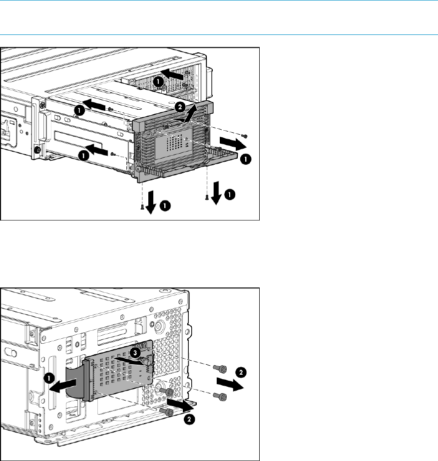
NOTE: There are two screws on the bottom, four screws on the sides (two on each side),
and two screws hidden behind the handle.
13. Disconnect the LED display board from the drive backplane by pinching the ends of the LED
display board together (1). Remove the four screws from the LED display board (2). Then,
remove the LED display board from the drive drawer (3).
Replacing the front LED display board (full)
To replace the front LED display board (full):
116 Removing and replacing hardware components
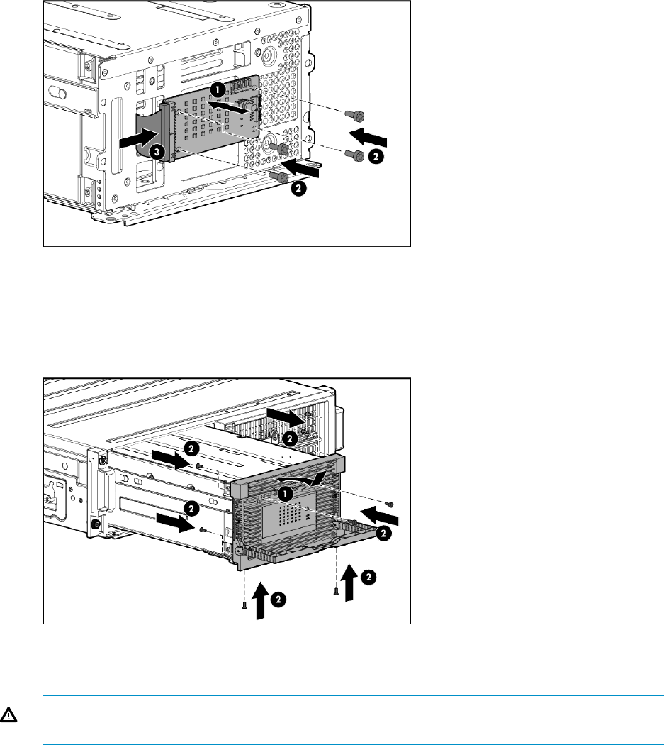
1. Install the replacement LED display board (1), replace the four LED display board screws (2),
and then reconnect the LED display board to the drive drawer (3).
2. Replace the front bezel with the handle at a 90 degree angle making sure the bottom pins
are aligned with the bottom holes (1), and replace the front bezel screws (2).
NOTE: There are two screws on the bottom, four screws on the sides (two on each side),
and two screws hidden behind the handle.
3. Close the drawer handle.
4. Place the enclosure in the rack, and tighten the two retaining screws.
WARNING! The messaging system enclosure is heavy, even after removing the hard drives.
Always use at least two people to replace the messaging system in the rack.
5. Replace the server blades into their original bays.
6. Extend the hard drive drawer:
1. Press upward on the release button on the hard drive drawer (1).
2. Pull the drawer handle down 90 degrees (2).
Removing and replacing the front LED display board (full) 117
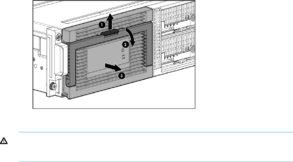
3. Extend the hard drive drawer (3).
7. Replace all hard drives.
WARNING! Carefully check the drive labels provided with the replacement drives, and then
install the hard drives in the same slots from which you removed them. If the drives are not
installed in the correct slots, the system might fail.
8. Push the drive drawer back into the messaging system enclosure.
9. Plug the cables into the back of the messaging system enclosure into their original locations.
10. Power on the system messaging system by pressing the power button On.
11. Verify that the replacement component is working properly by checking the associated LED
statusTable 4 (page 53).
12. Confirm that the messaging system has resumed normal operations.
Removing and replacing a drive drawer
This section describes how to remove and replace the drive drawer in the messaging system.
Removing the drive drawer
To remove the drive drawer:
1. Use System Manager to identify the failed component.
2. Verify the failed component by checking for a blinking amber LED on the failed component
Table 4 (page 53).
3. Power off the system:
1. Shut down blade 2 by clicking on Start and then Shut Down while you are connected to
blade 1.
2. Shut down blade 1 by clicking on Start and then Shut Down while you are connected to
blade 2.
3. Power off the expansion nodes, if present, by pressing and holding the power button at
the back.
4. Power off the storage solution by pressing and holding the power button at the back of
the enclosure.
5. Disconnect the power cables.
4. Extend the hard drive drawer:
1. Press upward on the release button on the hard drive drawer (1).
2. Pull the drawer handle down 90 degrees (2).
118 Removing and replacing hardware components

3. Extend the hard drive drawer (3).
5. Label the hard drives.
NOTE: Use the drive labels provided with the replacement drive drawer when removing the
drives to ensure you replace the drives in the correct order.
6. Remove all hard drives.
IMPORTANT: You must install the hard drives into the same slots from which they were
removed, or the system might fail.
7. Push the drive drawer back into the messaging system enclosure.
8. Label each server blade, and the remove both server blades.
9. Label the cables, and then unplug all cables from the back of the messaging system enclosure.
10. Unscrew the retaining screws from the bezel ears, and then remove the enclosure from the
rack.
WARNING! The messaging system enclosure is heavy, even after removing the hard drives.
Always use at least two people to remove the messaging system from the rack.
11. Remove the top back panel by pressing the panel release button and lifting the latch to slide
the top back panel off.
12. Lift up on the drive fan release mechanism and remove the fan.
13. Push up on the SAS I/O module release button.
14. Push down on the SAS I/O module lever (1), and then remove the SAS I/O module (2).
Removing and replacing a drive drawer 119
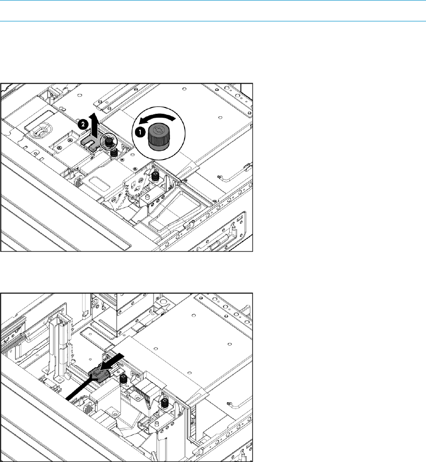
NOTE: You must repeat Steps 14 and 15 for the remaining SAS I/O module.
15. Press the hard drive drawer release button, and then pull the drawer handle down 90 degrees.
16. Extend the drive drawer.
17. Remove the plug bracket (2) from the coil power plug by removing the thumbscrew (1).
18. Unplug the coil power assembly from the midplane board.
120 Removing and replacing hardware components

19. Press the release mechanism on the side rail (1), and then pull the hard drive drawer fully out
of the enclosure (2).
CAUTION: The hard drive drawer is heavy, even after removing the hard drives. Make sure
the drawer is fully supported as you remove it from the enclosure.
Replacing the drive drawer
To replace the drive drawer:
1. Unlock the side enclosure rail and push it into the back enclosure.
2. Align the bottom replacement drive drawer rails with the bottom enclosure rails.
Removing and replacing a drive drawer 121

3. Align the side rails and then push the replacement drive drawer partially back into the
messaging system enclosure until approximately 2 inches of the drawer is still out of the
enclosure.
CAUTION: Do not push the drive drawer completely into the enclosure. You must first connect
the power coil assembly to prevent damaging the power coil assembly.
4. Pull the cable slightly out of the coil power plug and connect it to the midplane board.
5. Reattach the coil power plug sheet metal bracket (1) and tighten the thumbscrew (2).
122 Removing and replacing hardware components
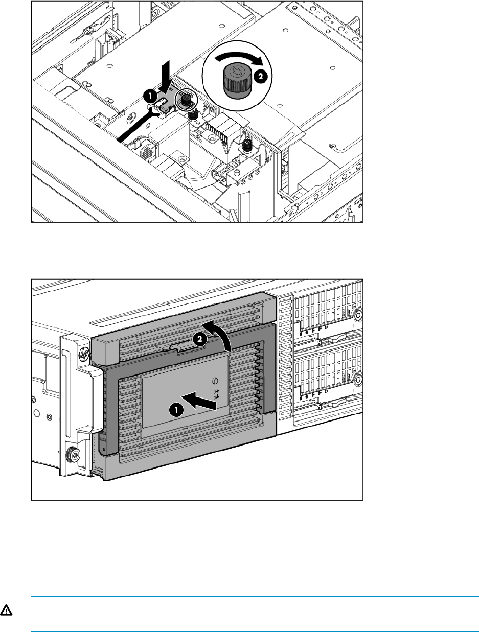
6. Push the drive drawer fully back into the messaging system enclosure (1) and the handle back
into place (2).
7. Replace the top back panel.
8. Replace the drive fan.
9. Replace both SAS I/O modules.
10. Place the enclosure into the rack, and secure the enclosure by tightening the two retaining
screws.
WARNING! The messaging system enclosure is heavy, even after removing the hard drives.
Always use at least two people to replace the messaging system in the rack.
11. Replace both server blades and ensure they are placed into their original bays.
12. Extend the hard drive drawer:
1. Press upward on the release button on the hard drive drawer (1).
2. Pull the drawer handle down 90 degrees (2).
Removing and replacing a drive drawer 123
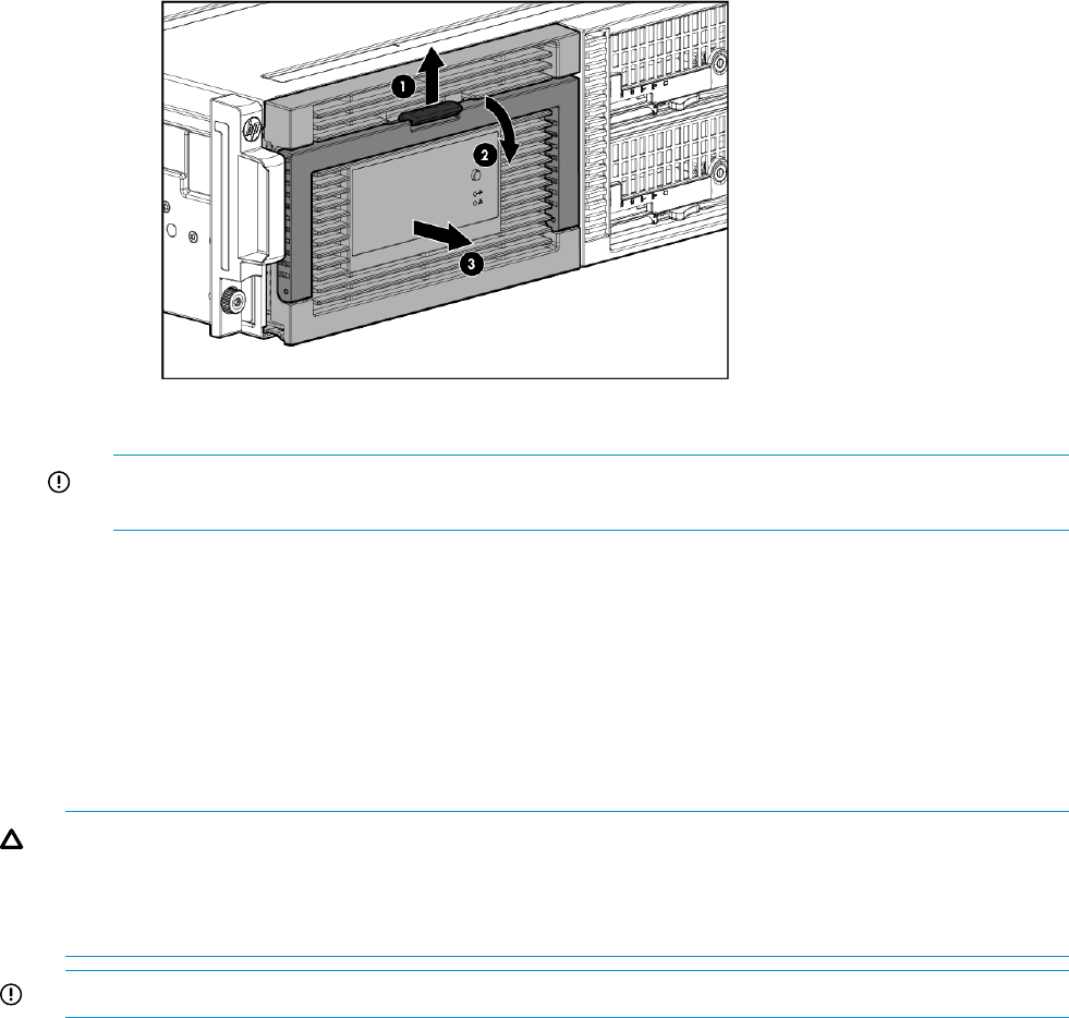
3. Extend the hard drive drawer (3).
13. Replace all hard drives.
IMPORTANT: Install the hard drives in the same slots from which you removed them or the
system might fail. Use the drive labels to ensure they are replaced in the correct order.
14. Push the drive drawer back into the messaging system enclosure.
15. Plug in all cables to the back of the messaging system enclosure and ensure that all cables
are returned to their original locations.
16. Power on the messaging system.
17. Verify and confirm that the replacement component is working properly by checking the
component LED status.
Removing and replacing the drive drawer hard drive
CAUTION: Do not replace the hard drive with an SATA drive. Be sure to replace the hard drive
only with an approved SAS drive.
CAUTION: Do not replace the drive drawer hard drive during peak data transfer times. Make
sure the hard drive LED is off before you remove the hard drive.
IMPORTANT: Be sure to unpack the replacement part before you remove the existing component.
This section describes how to remove and replace the hard drive in the messaging system. After
replacing the hard drives, the approximate wait times for viewable disk LED activity vary.
Removing the drive drawer hard drive
To remove the drive drawer hard drive:
1. Use System Manager to identify the failed component.
2. Verify the failed component by checking for a blinking amber LED on the failed component.
3. Extend the hard drive drawer:
1. Press upward on the release button on the hard drive drawer (1).
2. Pull the drawer handle down 90 degrees (2).
124 Removing and replacing hardware components
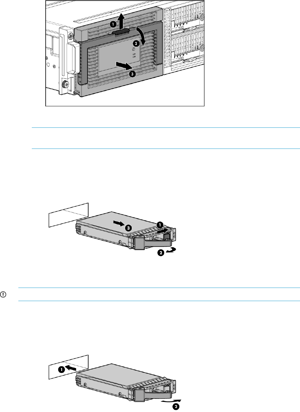
3. Extend the hard drive drawer (3).
4. Locate the failed hard drive.
NOTE: The initial indicator LED on the failed drive is amber. Use the hard drive bay labels
to help identify the failed drive.
5. To remove the failed hard drive:
1. Press the release button (1).
2. Pull the release lever (2).
3. Remove the hard drive (3).
Replacing the drive drawer hard drive
IMPORTANT: You must be prepared to reboot the storage solution after completing this procedure.
To replace the drive drawer hard drive:
1. Install the hard drive:
1. Insert the replacement hard drive with the lever in the open position (1).
2. Push the release lever into place (2).
Removing and replacing the drive drawer hard drive 125
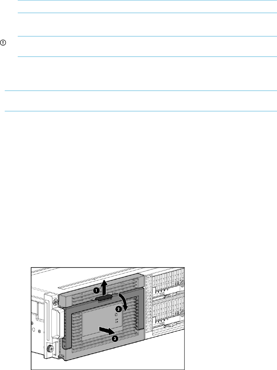
2. Push the drive drawer back into the messaging system enclosure.
3. Verify that the replacement component is working properly by checking the associated LED
status.
NOTE: This may require a wait time of less than 15 seconds for the LED status to appear.
4. Confirm the messaging system has resumed normal operations.
5. Confirm the hard drive firmware version.
IMPORTANT: You must reboot the storage solution after updating the drive drawer hard
drive firmware.
Removing and replacing the drive drawer rails (side or bottom)
This section describes how to remove and replace the drive drawer rails in the messaging system.
NOTE: Spare rail kits consist of rail pairs, one enclosure bay rail, and one drive drawer rail.
See “Removing and replacing the enclosure rails” (page 132) for enclosure rail instructions.
Removing the drive drawer rails
To remove the drive drawer rails:
1. Power off the system:
1. Shut down blade 2 by clicking on Start and then Shut Down while you are connected to
blade 1.
2. Shut down blade 1 by clicking on Start and then Shut Down while you are connected to
blade 2.
3. Power off the expansion nodes, if present, by pressing and holding the power button at
the back.
4. Power off the storage solution by pressing and holding the power button at the back of
the enclosure.
5. Disconnect the power cables.
2. Extend the hard drive drawer:
1. Press upward on the release button on the hard drive drawer (1).
2. Pull the drawer handle down 90 degrees (2).
3. Extend the hard drive drawer (3).
3. Label the hard drives.
126 Removing and replacing hardware components
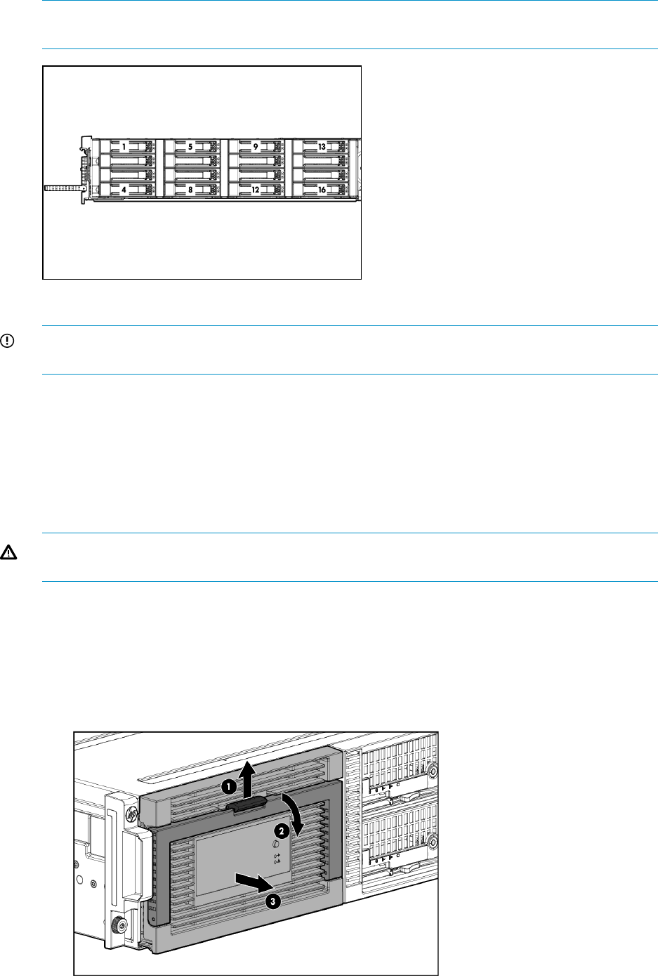
NOTE: Use the drive labels provided with the replacement drive drawer rails to label the
hard drives to ensure you replace the drives in the correct order.
4. Remove all hard drives.
IMPORTANT: Install the hard drives in the same slots from which you removed them or the
system might fail.
5. Push the drive drawer back into the messaging system enclosure.
6. Label each server blade, and then remove both server blades.
7. Label the cables connected to the back of the enclosure so they can be returned to their original
locations.
8. Unplug all cables from the back of the messaging system enclosure.
9. Unscrew the retaining screws from the bezel ears, and then remove the enclosure from the
rack.
WARNING! The messaging system enclosure is heavy, even after removing the hard drives.
Always use at least two people to remove the messaging system from the rack.
10. Remove the top back panel by pressing the panel release button and lifting the latch to slide
the top back off.
11. Extend the hard drive drawer:
1. Press upward on the release button on the hard drive drawer (1).
2. Pull the drawer handle down 90 degrees (2).
3. Extend the hard drive drawer (3).
Removing and replacing the drive drawer rails (side or bottom) 127
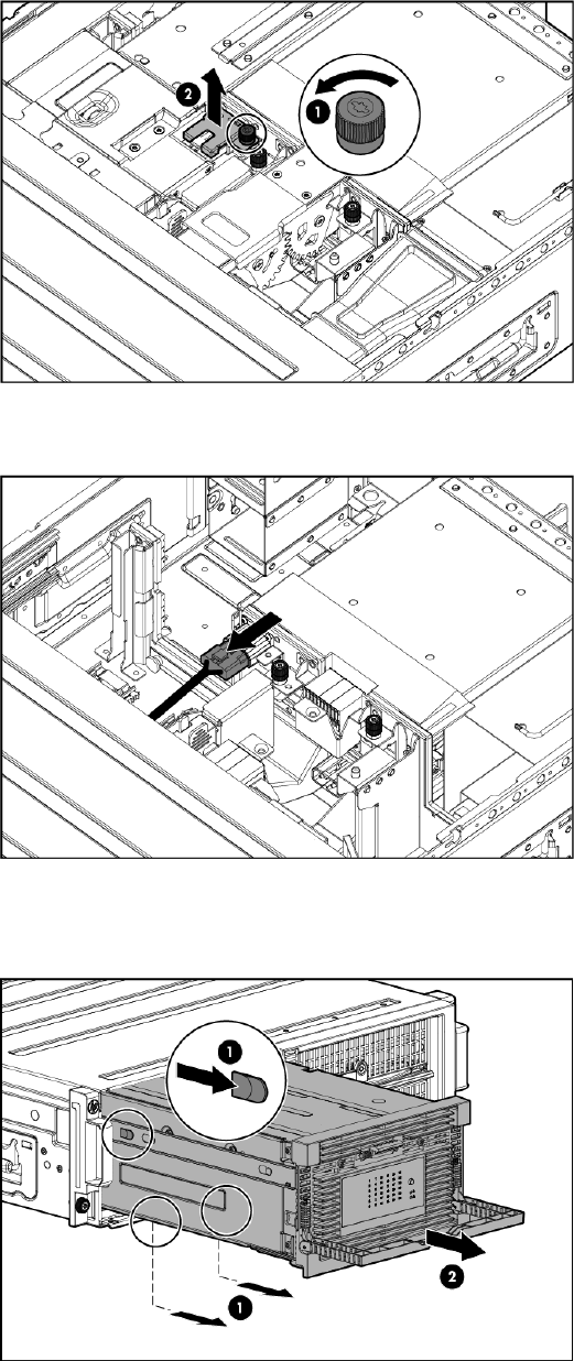
12. Remove the plug bracket (2) from the coil power plug by removing the thumbscrew (1).
13. Unplug the coil power assembly from the midplane board.
14. Press the release mechanism on the side rail (1), and then pull the hard drive drawer fully out
of the enclosure (2).
128 Removing and replacing hardware components
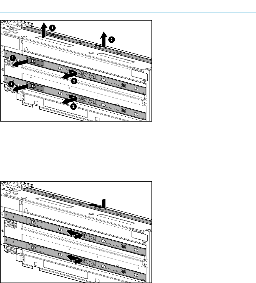
15. Lift the release tab on the side or bottom rail (1), and then slide the rail toward the front of the
drive drawer to remove (2) the rail.
NOTE: Repeat this step for all rails.
Replacing the drive drawer rails
To replace the drive drawer rails:
1. Align the replacement rail with the tabs, and slide it toward the back of the drive drawer until
the rail locks into place.
Removing and replacing the drive drawer rails (side or bottom) 129

2. Align the replacement drive drawer rail with the three enclosure rails and then push the drive
drawer partially back into the messaging system enclosure so that approximately 2 inches of
the drawer is still out of the enclosure.
CAUTION: Do not push the drive drawer completely into the enclosure. You must first connect
the power coil assembly to prevent damaging the power coil assembly.
3. Pull the cable slightly out of the coil power plug and connect it to the midplane board.
4. Reattach the coil power plug bracket (1) and tighten the thumbscrew (2).
130 Removing and replacing hardware components
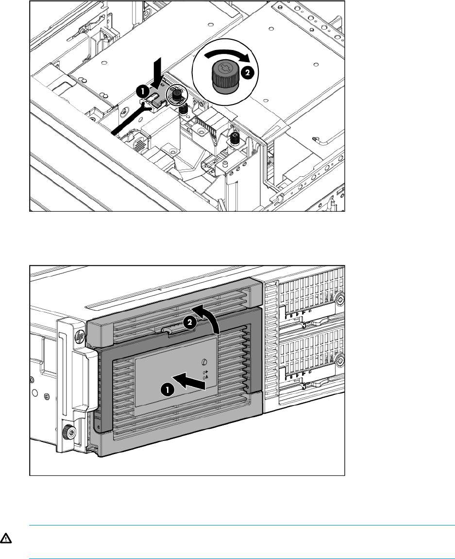
5. Push the drive drawer fully back into the messaging system enclosure (1) and the handle back
into place (2).
6. Replace the top back panel.
7. Place the enclosure in the rack, and tighten the two retaining screws.
WARNING! The messaging system enclosure is heavy, even after removing the hard drives.
Always use at least two people to replace the messaging system in the rack.
8. Replace both server blades in their original bays.
9. Extend the hard drive drawer:
1. Press upward on the release button on the hard drive drawer (1).
2. Pull the drawer handle down 90 degrees (2).
Removing and replacing the drive drawer rails (side or bottom) 131
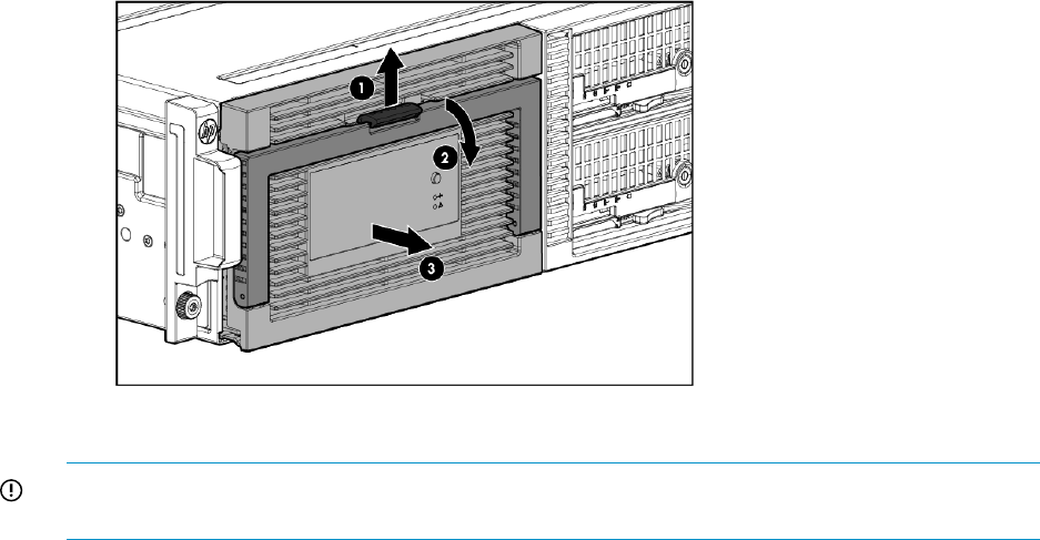
3. Extend the hard drive drawer (3).
10. Replace all hard drives.
IMPORTANT: Install the hard drives in the same slots from which you removed them or the
system might fail. Use the drive labels to ensure they are replaced in the correct order.
11. Push the drive drawer back into the messaging system enclosure.
12. Plug in all cables at the back of the messaging system enclosure to their original locations.
13. Power on the system by pressing the power button On.
14. Confirm the messaging system has resumed normal operations.
Removing and replacing the enclosure rails
This section describes how to remove and replace the enclosure rails in the messaging system.
Removing the enclosure rails
To remove the enclosure rails:
1. Power off the system:
1. Shut down blade 2 by clicking on Start and then Shut Down while you are connected to
blade 1.
2. Shut down blade 1 by clicking on Start and then Shut Down while you are connected to
blade 2.
3. Power off the expansion nodes, if present, by pressing and holding the power button at
the back.
4. Power off the storage solution by pressing and holding the power button at the back of
the enclosure.
5. Disconnect the power cables.
2. Extend the hard drive drawer:
1. Press upward on the release button on the hard drive drawer (1).
2. Pull the drawer handle down 90 degrees (2).
132 Removing and replacing hardware components
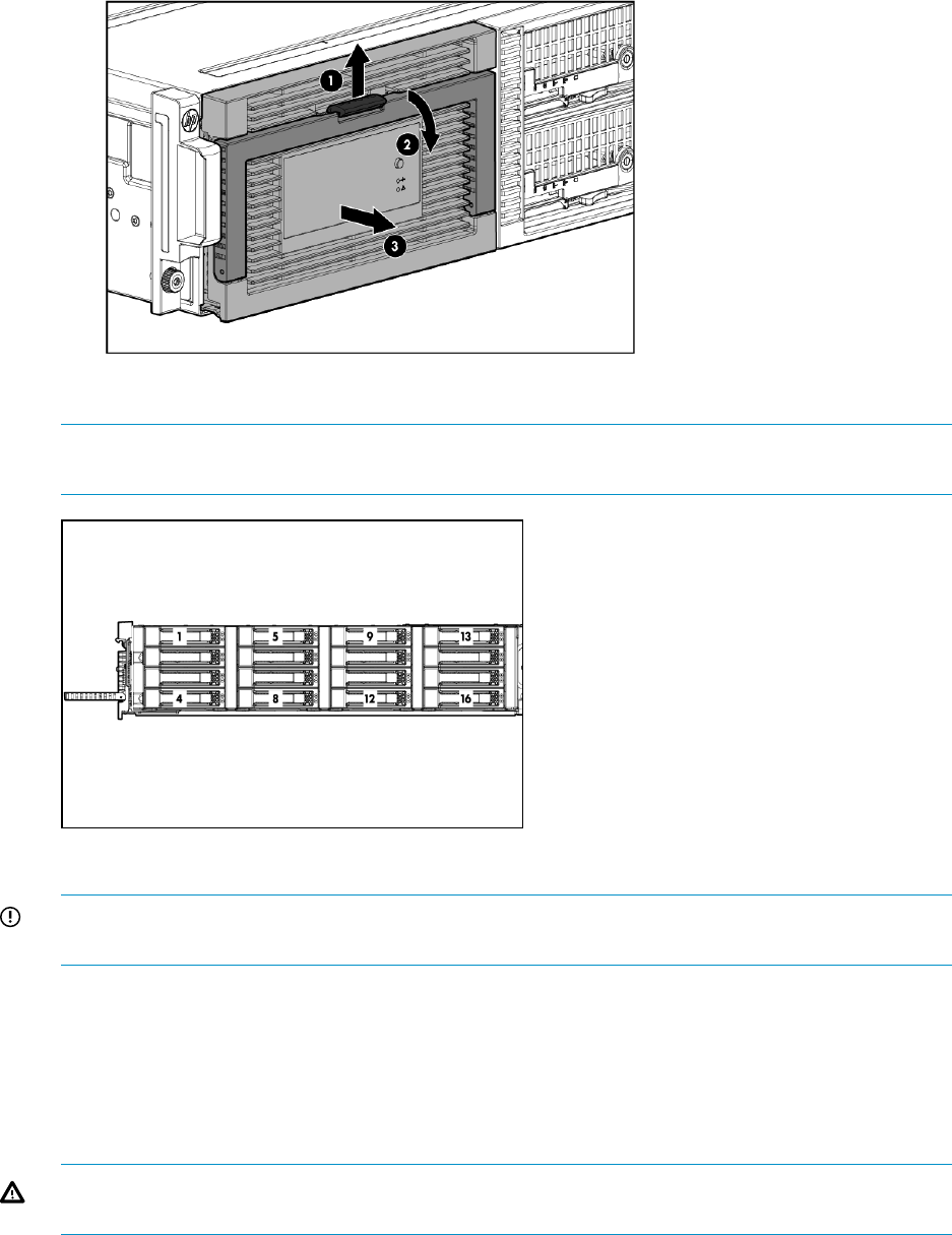
3. Extend the hard drive drawer (3).
3. Label the hard drives.
NOTE: Use the drive labels provided with the replacement rack rails to label the hard drives
to ensure you replace the drives in the correct order.
4. Remove all hard drives.
IMPORTANT: Install the hard drives in the same slots from which you removed them or the
system might fail.
5. Push the drive drawer back into the messaging system enclosure.
6. Label each server blade, and then remove both server blades.
7. Label the cables connected to the back of the enclosure, and then unplug all cables from the
back of the messaging system enclosure.
8. Unscrew the retaining screws from the bezel ears, and then remove the enclosure from the
rack.
WARNING! The messaging system enclosure is heavy, even after removing the hard drives.
Always use at least two people to remove the messaging system from the rack.
9. Extend the hard drive drawer:
Removing and replacing the enclosure rails 133
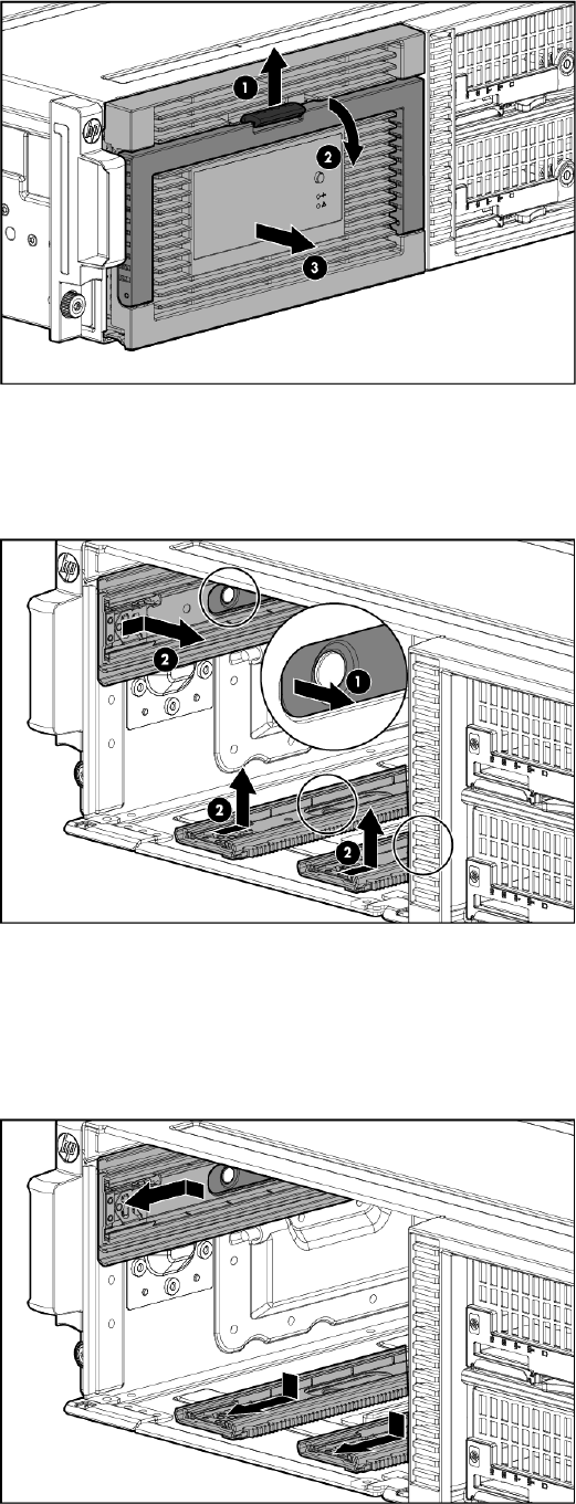
10. Remove the hard drive drawer from the messaging system enclosure.
11. Lift the release mechanism on the rail (side or bottom) (1), and then push the rail back and up
to release and remove the rail (2).
Replacing the enclosure rails
To replace the enclosure rails:
1. Align the replacement rail, and then attach it by sliding the rail toward the front of the enclosure.
134 Removing and replacing hardware components
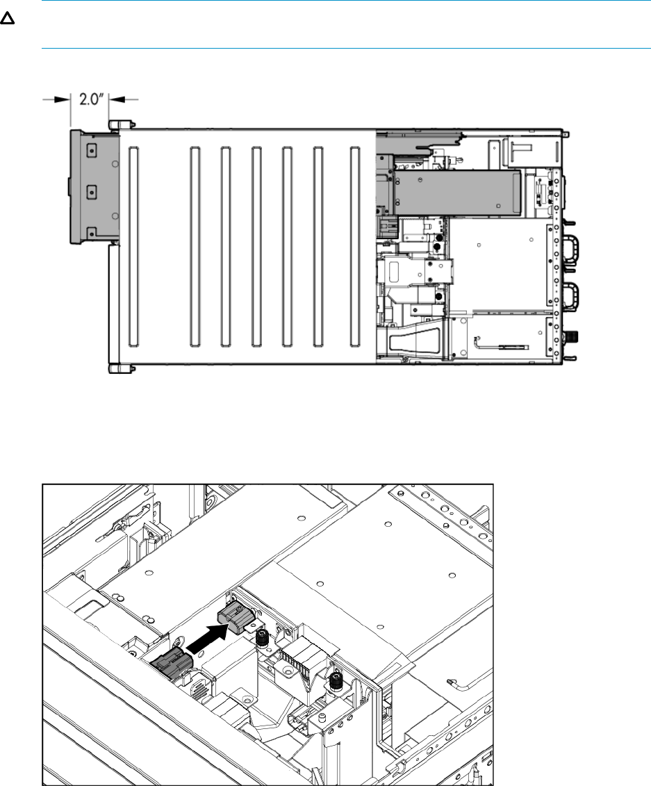
2. Align the replacement drive drawer rail with the three enclosure rails and then push the drive
drawer partially back into the messaging system enclosure so that approximately 2 inches of
the drawer is still out of the enclosure.
CAUTION: Do not push the drive drawer completely into the enclosure. You must first connect
the power coil assembly to prevent damaging the power coil assembly.
3. Pull the cable slightly out of the coil power plug and connect it to the midplane board.
4. Reattach the coil power plug bracket (1) and tighten the thumbscrew (2).
Removing and replacing the enclosure rails 135

5. Push the drive drawer fully back into the messaging system enclosure (1) and the handle back
into place (2).
6. Place the messaging system back in the rack, and tighten the two retaining screws.
WARNING! The messaging system enclosure is heavy, even after removing the hard drives.
Always use at least two people to replace the messaging system in the rack.
7. Replace both server blades into their original bays.
8. Extend the hard drive drawer:
136 Removing and replacing hardware components
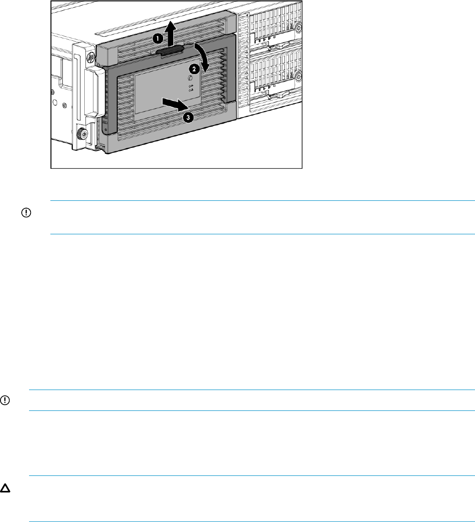
9. Replace all hard drives.
IMPORTANT: Install the hard drives in the same slots from which you removed them or the
system might fail. Use the drive labels to ensure they are replaced in the correct order.
10. Push the drive drawer back into the messaging system enclosure.
11. Plug in all cables at the back of the messaging system enclosure into their original locations.
12. Power on the system by pressing the power button On.
13. Confirm that the messaging system has resumed normal operations.
Removing and replacing the rack rails
For detailed instructions on installing the rack rails, see the HP StorageWorks 3U messaging system
Rail Kit Installation Instructions.
Removing and replacing server blade(s)
IMPORTANT: Be sure to unpack the replacement part before you remove the existing component.
This section describes how to remove and replace the server blades and blade components in the
messaging system.
Removing the server blade
CAUTION: Do not use the server blade release lever to lift or carry the server blade. Always
support the weight of the server blade by handling the chassis directly. Improper use can damage
the release lever and the server blade.
To remove the server blade:
1. Use the Storage Manager to identify the failed component.
2. Verify the failure by checking for a blinking amber LED on the failed component.
3. Power off the appropriate server blade by clicking on Start and then Shut Down.
4. Push the button to release the handle (1), pull the handle toward you (2), and then remove
the server blade (3).
Removing and replacing the rack rails 137

5. Place the server blade on a flat, level work surface.
WARNING! To reduce the risk of personal injury from hot surfaces, allow the drives and
the internal system components to cool before touching them.
CAUTION: To prevent damage to electrical components, properly ground the server blade
before beginning any installation procedure. Improper grounding can cause ESD damage.
Replacing the server blade
To replace the server blade:
1. Install the server blade (1), and then push the handle into place with the handle open (2).
2. Power on the server blade.
3. Confirm the system has resumed normal operations.
Removing and replacing the server blade hard drive
IMPORTANT: You must install a supported optional controller for hot-plug capability and drive
LED support.
This section describes how to remove and replace the server blade hard drive in the messaging
system.
Removing the server blade hard drive
To remove the server blade hard drive:
1. Use System Manager to identify the failed component.
2. Verify the failed component by checking for a blinking amber LED on the failed component.
3. Back up all data on the hard drive.
138 Removing and replacing hardware components
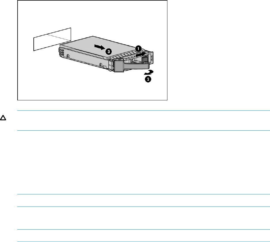
4. Push the button to release the handle (1), pull the handle toward you (2), and then remove
the hard drive from the server blade (3).
CAUTION: To prevent improper cooling and thermal damage, replace the drive quickly. Do
not operate the server unless all bays are populated.
Replacing the server blade hard drive
To replace the server blade hard drive:
1. Install the replacement server blade hard drive with the latch open and then push the latch
closed to secure it.
2. Verify that the server blade hard drive is working properly by checking the associated LED
status.
NOTE: This may require a wait time of less than 15 seconds for the LED status to appear.
3. Confirm that the messaging system has resumed normal operations.
4. Confirm the firmware version.
NOTE: You must reboot the storage solution after updating a server blade hard drive.
Removing and replacing the controller and controller server blade
components
This section describes how to remove and replace the controller and controller components in the
messaging system.
Removing the controller card
To remove the controller card:
1. Use System Manager to identify the failed component.
2. Back up all data.
3. Close all applications.
4. To power off the server blade, click Start and then select Shut down.
5. Push the button to release the handle (1), pull the handle toward you (2), and then remove
the server blade from the enclosure (3).
Removing and replacing the controller and controller server blade components 139
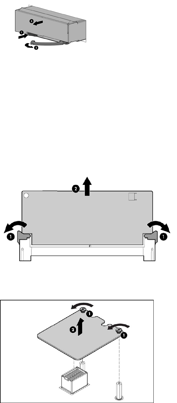
6. Press the release button on the access panel and slide the access panel to the left to remove
the access panel.
7. The original cache module is connected to a capacitor pack, so observe the cache module
LEDs.
•If the amber LED is solid, data transfer to the flash device on the cache module is in
progress. Do not remove the cache module until the amber LED is off, and then continue
with the next step.
•If the amber LED is not lit, proceed to the next step.
8. Open the ejector latches (1) on each side of the cache module slot.
Typically, opening the ejector latches ejects the cache module automatically. If the module
does not eject automatically after you open the ejector latches, remove the cache module (2)
by grasping only the edges.
9. Remove the cache module and the capacitor from the blade.
10. Loosen two captive screws and remove the controller card.
140 Removing and replacing hardware components
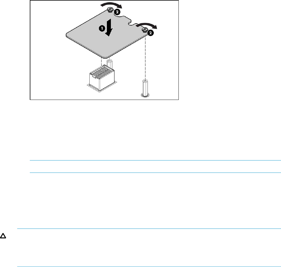
Replacing the controller card
To replace the controller card:
1. Install the cache module and capacitor in the cache module slot of the replacement controller.
2. Close the ejector latches on the cache module slot.
3. Install the replacement controller card (1). Press down on the connector to seat the card (2).
4. Tighten the captive screws.
5. Replace the capacitor in its cradle.
6. Install the access panel.
7. Install the server blade in the enclosure.
8. Confirm that the replacement to P1210m controller is running current firwmare (see“Upgrading
a component's firmware version” (page 64)).
NOTE: You must reboot the storage solution after updating firmware on the server blade.
Removing and replacing the P1210m cache module
This section describes how to remove and replace the P1210m cache module in the messaging
system.
Removing the P1210m cache module
CAUTION: Do not use this controller with P1210m cache modules designed for other controller
models because the controller can malfunction and you can lose data.
CAUTION: Electrostatic discharge can damage electronic components. Be sure you are properly
grounded before performing this procedure.
To remove the P1210m cache module:
1. Back up all data.
2. Close all applications.
3. Power off the server blade.
4. Remove the server blade from the enclosure by pushing the button to release the handle (1),
pulling the handle toward you (2), and then removing the server blade from the enclosure (3).
Removing and replacing the controller and controller server blade components 141

5. Press the release button on the access panel and slide the access panel to the left to remove
it.
6. Since the original P1210m cache module is connected to a capacitor pack, observe the cache
module LEDs.
•If the amber P1210m cache LED is solid, data transfer to the flash device on the cache
is in progress. Do not remove the P1210m cache until the amber LED is off, and then
continue with the next step.
•If the amber P1210m cache LED is not lit proceed to the next step.
7. Open the ejector latches on each side of the P1210m cache module slot.
Typically, opening the ejector latches ejects the cache module automatically. If the module
does not eject automatically after you open the ejector latches, remove the cache module (2)
by grasping only the edges.
142 Removing and replacing hardware components
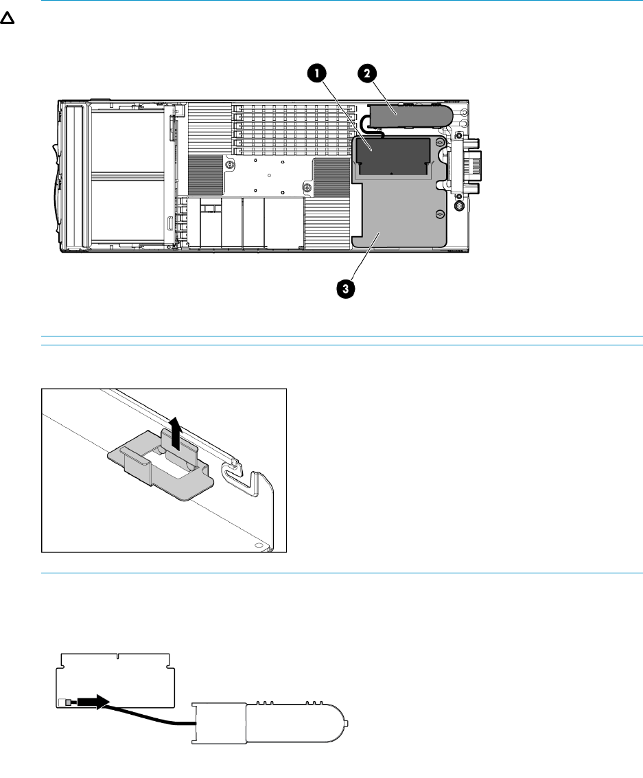
8. Remove the capacitor pack (2).
The P1210m cache module is shown as (1), and the controller card is (3).
CAUTION: Wear gloves or use care when removing the capacitor to avoid physical injury.
NOTE: Be sure to first remove the capacitor pack bracket.
9. Disconnect the capacitor pack cable from the connector on the top of the cache module.
Replacing the cache module
To replace the cache module:
1. Connect the capacitor pack cable to the replacement cache module.
2. Install the replacement cache module in the cache module slot (1).
3. Close the ejector latches on the cache module slot (2).
Removing and replacing the controller and controller server blade components 143
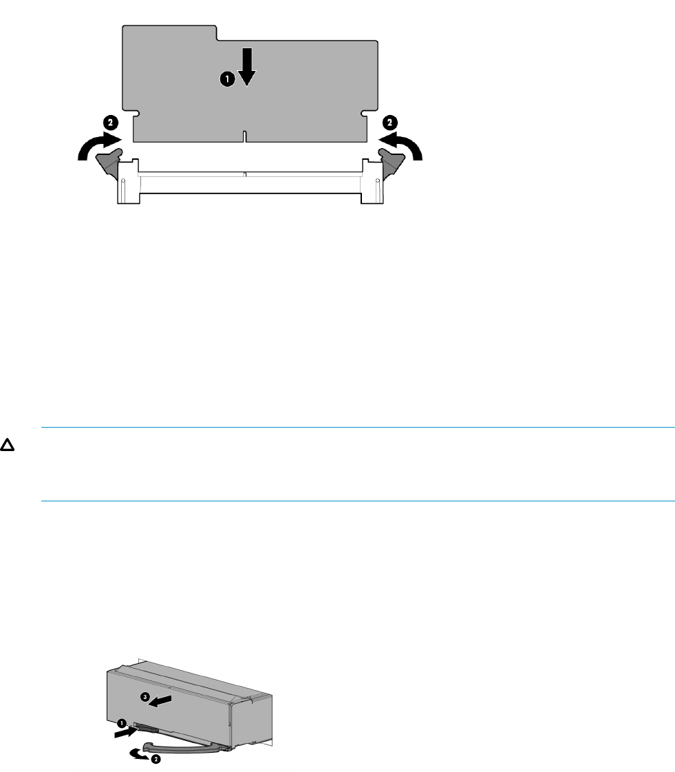
4. Install the capacitor pack bracket and insert the capacitor pack on the chassis wall.
5. Install the access panel.
6. Install the server blade into the enclosure.
Removing and replacing the capacitor pack
This section describes how to remove and replace the capacitor pack in the messaging system.
Removing the capacitor pack
CAUTION: Wear gloves or use care when removing the capacitor pack to avoid physical injury.
CAUTION: Electrostatic discharge can damage electronic components. Be sure you are properly
grounded before performing this procedure.
To remove the capacitor pack:
1. Back up all data.
2. Close all applications.
3. Power off the server blade.
4. Remove the server blade from the enclosure by pushing the button to release the handle (1),
pulling the handle toward you (2), and then removing the server blade from the enclosure (3).
5. Press the release button on the access panel and slide the access panel to the left to remove
it.
6. Since the original capacitor pack is connected to a cache module, observe the cache module
LEDs.
•If the amber cache LED is solid, data transfer to the flash device on the cache is in progress.
Do not remove the cache until the amber LED is off, and then continue with the next step.
•If the amber cache LED is not lit, proceed to the next step.
144 Removing and replacing hardware components
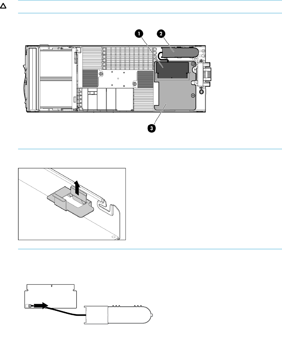
7. Open the ejector latches on each side of the cache module slot.
Typically, opening the ejector latches ejects the cache module automatically. If the module
does not eject automatically after you open the ejector latches, remove the cache module by
grasping only the edges.
8. Remove the cache module (1) from the controller card (3) and the capacitor pack (2) from the
server blade.
CAUTION: Wear gloves or use care when removing the capacitor to avoid physical injury.
NOTE: Be sure to first remove the capacitor pack bracket.
9. After you remove the cache module, disconnect the capacitor cable from the module.
Replacing the capacitor pack
To replace the capacitor pack:
Removing and replacing the controller and controller server blade components 145

1. Connect the replacement capacitor pack to the cache module.
2. Install the cache module in the cache module slot.
3. Install cache module on the controller, and then close the ejector latches on the cache module
slot.
4. Install the capacitor pack bracket and insert the replacement capacitor pack on the chassis
wall.
5. Install the access panel.
6. Install the server blade in the enclosure.
IMPORTANT: After installing a capacitor pack, you might see a POST message during reboot
indicating that the array accelerator (cache) is disabled temporarily. This behavior is normal
because the new capacitor pack is likely to have a low charge.
The controller operates properly while the capacitor pack is recharging, although the performance
advantage of the array accelerator is absent. You do not need to take any action because the
recharge process begins automatically when you install the capacitor pack. When the capacitor
pack has been charged to a predetermined level, the array accelerator is enabled automatically.
146 Removing and replacing hardware components

8 Messaging System recovery
This chapter describes how to use the System Recovery DVD that is provided with your messaging
system.
The E5000 System Recovery DVD
The E5000 System Recovery DVD that is provided with your storage system allows you to install
an image or recover from a catastrophic failure.
At any later time, you may boot from the DVD and restore the server to the factory condition. This
allows you to recover the system if all other means to boot the server fail.
While the recovery process makes every attempt to preserve the existing data volumes, you should
have a backup of your data if at all possible before recovering the system.
During the recovery process, the original OS logical drive is overwritten. All data on that drive is
erased.
Restoring the factory image with a DVD or USB flash device
1. Do one of the following:
a. For direct access, attach the SUV cable (supplied with the E5300 Messaging System) to
the port on the front of the server blade you wish to recover. Connect a monitor and USB
mouse to the SUV cable. Then, using the remaining USB connector on the SUV cable,
connect either a USB DVD drive (and insert the System Recovery DVD) or a bootable USB
flash device (prepared with a System Recovery image).
b. For remote management access, connect to the server using iLO from a client PC. Insert
the System Recovery DVD in the client PC or attach a bootable USB flash device that has
been prepared with a System Recovery image.
2. Reboot the server blade to either the USB flash device or USB DVD drive.
The system BIOS attempts to boot to the USB device first by default. Watch the monitor output
during the boot as you may need to press a key to boot to the USB media.
NOTE: If directly connected, you may have to change the BIOS settings to ensure proper
boot sequence. If connected remotely, you may have to change some iLO settings to ensure
proper boot sequence.
3. Click Restore Factory Image.
The recovery process completes with little user intervention required. The server automatically
reboots more than once.
IMPORTANT: Do not interrupt the recovery process.
When the upgrade process is complete, the system automatically logs in as the Administrator
using “HPinvent!” as the password, and then prompts you to change the Administrator
password.
4. Remove the directly connected DVD or flash device (or remotely connected iLO virtual DVD
or flash device) from the server.
Using a USB flash drive for messaging system recovery
Creating a System Recovery USB Flash drive is supported on Windows Vista, Windows 7, Windows
Storage Server 2008, and Windows Storage Server 2008 R2 operating systems only.
The E5000 System Recovery DVD 147

If you create a backup copy of the System Recovery DVD using a USB Flash Drive, you can also
use it to restore the system. To create system recovery media using a USB Flash drive, follow the
instructions below.
To create a system recovery USB Flash Drive:
1. Obtain a blank 4 GB or larger USB Flash Drive.
2. Insert the USB Flash device into your workstation or laptop.
3. Open an elevated command prompt with Administrator privileges.
4. At the command prompt, enter diskpart.
5. At the diskpart prompt, enter list disk.
6. Identify the disk number that corresponds to the flash drive. This is typically the last disk listed.
7. Enter sel disk <USB drive number>. For example, sel disk 4.
8. Enter clean. This deletes everything from the USB flash device, so ensure you have the proper
disk selected.
9. Enter create par primary.
10. Enter sel par 1.
11. Enter format fs=fat32 quick.
NOTE: If your USB Flash Drive does not support the FAT32 file system, format the drive as
NTFS instead. Omitting the quick parameter lengthens the format time considerably.
12. Enter active to mark the partition as active.
13. Enter assign letter=<drive letter> to assign a drive letter to the USB drive. For
example, assign letter=U.
14. Enter exit to quit diskpart context commands.
15. Insert the System Recovery DVD into the computer.
16. Using Windows Explorer or a comparable utility, open the DVD so that all contents are visible,
including hidden and system files.
17. Select all of the files (including bootmgr) on the DVD.
18. Copy all of the selected files to the root of the USB drive.
Managing disks after a system restoration
When you restore a system using the System Recovery DVD, the E5000 Configuration Wizard
automatically runs and detects the existence of the data volumes (volumes managed by the P1210m
controller). The wizard remounts the data volumes as appropriate using the mount points in the
C:\ExchangeDatabases directory. For example, the following mount points may be found:
•C:\ExchangeDatabases\Recovery
•C:\ExchangeDatabases\VOL1
•C:\ExchangeDatabases\VOL2
•C:\ExchangeDatabases\VOL3
Restoration in non-production environments
If the E5300 Messaging System was in a non-production environment prior to the system recovery
and the Exchange data does not need to be retained, the data on the appropriate volumes should
be deleted. This includes the mailbox databases and logs found in the mount points listed under
C:\ExchangeDatabases. The HUB transport database and logs (located on the H:\drive) should
also be deleted. The E5000 Exchange Deployment Tool can be used to create a fresh deployment
of Exchange 2010.
148 Messaging System recovery

Restoration in production environments
If the E5300 Messaging System was in a production environment and the Exchange data needs
to be retained, follow the appropriate Exchange recovery steps for your situation. Remember that
the E5000 system uses a multi-role Exchange configuration with the Client Access Server (CAS),
Hub Transport Server (HT), and Mailbox Server (MBX) roles installed on each of the two nodes.
Do not utilize the E5000 Exchange Deployment Tool in this situation. You can recover a lost
Exchange server by using the Setup /m:RecoverServer switch in Microsoft Exchange Server
2010. See also http://technet.microsoft.com/en-us/library/dd638206.aspx.
Managing disks after a system restoration 149

9 Support and other resources
Contacting HP
HP technical support
For worldwide technical support information, see the HP support website:
http://www.hp.com/support
Before contacting HP, collect the following information:
•Product model names and numbers
•Technical support registration number (if applicable)
•Product serial numbers
•Error messages
•Operating system type and revision level
•Detailed questions
Subscription service
HP recommends that you register your product at the Subscriber's Choice for Business website:
http://www.hp.com/go/e-updates
After registering, you receive email notification of product enhancements, new driver versions,
firmware updates, and other product resources.
Related information
The following documents provide related information:
•HP E5000 Series Messaging System for Microsoft Exchange documentation
◦HP E5000 Series Messaging System for Microsoft Exchange Quick Start Guide
◦HP StorageWorks 3U Storage System Rail Kit Installation Instructions
To locate the messaging system documents, go to http://www.hp.com/go/e5000, and then
click the support link.
You can also find these documents from the Manuals page of the HP Business Support Center
website:
http://www.hp.com/support/manuals
HP websites
For additional HP information, see the following HP websites:
•http://www.hp.com/go/E5000
•http://www.hp.com
•http://www.hp.com/go/storage
•http://www.hp.com/go/hpsim
•http://www.hp.com/service_locator
•http://www.hp.com/support/manuals
•http://www.hp.com/support/downloads
150 Support and other resources

•http://www.hp.com/storage/whitepapers
•http://www.hp.com/solutions/activeanswers/exchange
•http://h18013.www1.hp.com/products/servers/management/hpsim/index.html
Microsoft websites
For additional Microsoft information, see the following Microsoft websites:
•http://technet.microsoft.com/en-us/library/bb124558.aspx
•http://technet.microsoft.com/en-us/library/bb125255(EXCHG.80).aspx
•http://msdn.microsoft.com/en-us/library/aa562607(EXCHG.140).aspx
•http://msdn.microsoft.com/en-us/library/cc425506(EXCHG.80).aspx
Typographic conventions
Table 15 Document conventions
ElementConvention
Cross-reference links and e-mail addressesBlue text: Table 15 (page 151)
Website addressesBlue, underlined text: http://www.hp.com
•Keys that are pressed
•Text typed into a GUI element, such as a box
•GUI elements that are clicked or selected, such as menu
and list items, buttons, tabs, and check boxes
Bold text
Text emphasisItalic text
•File and directory names
•System output
•Code
•Commands, their arguments, and argument values
Monospace text
•Code variables
•Command variables
Monospace, italic text
Emphasized monospace textMonospace, bold text
Typographic conventions 151

WARNING! Indicates that failure to follow directions could result in bodily harm or death.
CAUTION: Indicates that failure to follow directions could result in damage to equipment or data.
IMPORTANT: Provides clarifying information or specific instructions.
NOTE: Provides additional information.
TIP: Provides helpful hints and shortcuts.
Rack stability
Rack stability protects personnel and equipment.
WARNING! To reduce the risk of personal injury or damage to equipment:
•Extend leveling jacks to the floor.
•Ensure that the full weight of the rack rests on the leveling jacks.
•Install stabilizing feet on the rack.
•In multiple-rack installations, fasten racks together securely.
•Extend only one rack component at a time. Racks can become unstable if more than one
component is extended.
152 Support and other resources

A EMU reference
CLI reference
The Command Line Interface is the primary interface for managing the Enclosure Manager. This
CLI is accessed via secure shell protocol over the LAN. Using the CLI is necessary for functions not
possible through any other mechanism or interface. For example, creating and setting Enclosure
Manager user accounts and passwords can be done through no other interface. Remotely powering
ON or OFF the enclosure can be done only with the CLI.
Command line conventions
CLI input is case-insensitive except when otherwise noted. Commands are organized into a tree,
with approximately 30 base commands. Each of these commands can have any number of
subcommands. Subcommands can also have further subcommands. Each command used in this
appendix follows the conventions listed in the following table.
Table 16 Command line conventions
DescriptionSymbol
Denotes the variable within the symbols that must be
substituted with a value, such as a user name. Symbols
must be removed.
<lowercase>
Denotes input to be entered as shown. Unless noted, symbol
is not case-sensitive.
UPPERCASE
Used to separate input options.|
Denotes a list of mandatory choices that must be made.
For example, SET ENCLOSURE UID {ON | OFF} must
be in one of the following forms:
SET ENCLOSURE UID ON
SET ENCLOSURE UID OFF
{ }
Denotes an optional argument or set of characters.[ ]
Used to enclose command arguments that contain spaces.” “
NOTE: All users logged into the CLI have administrator privilege. When a user account is created,
the account has administrator privilege.
Operational groups
Descriptions of the CLI commands are grouped below by functional areas instead of the parser
implementation which (as mentioned above) is a tree of commands, subcommands, and
sub-subcommands. The functional groups are:
•Authentication—user identity and authentication
•Time functions—Real Time Clock/Calendar control
•Role definition—access control
•Inventory and status—self explanatory
•Internet control—internal and external LAN management
•Server control –iLO dependent control of server
•Enclosure control—global control of enclosure, excluding JBOD management zone
•Forensic—global diagnostic context functions (not directed validation tests)
•Session—CLI session control
CLI reference 153
Authentication
This section defines EM authentication CLI functions.
ADD USER
Syntax
ADD USER "<user name>" ["<password>"]
Description
Adds a user to the system. If you do not provide a password, you are prompted for one. If script
mode is enabled and the password is not provided, the password is assigned an unmatched string.
This unmatched string requires an enclosure administrator to change the password to allow the
new user to access the system.
Restrictions
•You can add a maximum of 30 users, including the reserved accounts.
•The <user name> is case-sensitive and must be unique to all other user names and group
names. The user name must be 1 to 40 characters long and can include all alphanumeric
characters, the dash, and the underscore.
•The <user name> must begin with a letter.
•The <password> must be 3 to 40 characters long. The character set includes all printable
characters. If you do not enter a password, you are prompted to enter one.
•Reserved user names are: ALL (case insensitive), ADMINISTRATOR (case insensitive), switch1,
switch2, switch3, switch4, switch5, switch6, switch7, switch8, daemon, ldapuser, nobody,
tbmuser_, vcmuser_, root, and quire.
CLEAR SSHKEY
Syntax
CLEAR SSHKEY
Description
Disables a user account. The system immediately logs out the user and prevents the user from
logging in until the account is enabled.
This command is used in the factory to disable the ‘root’ user account. The root user account is
required to perform certain factory-only configuration and diagnostic operations when logged into
the Linux shell.
Restrictions
None
DOWNLOAD SSHKEY
Syntax
DOWNLOAD SSHKEY <url>
Description
Downloads an authorized key file to use with Secure Shell 2, which can contain the public keys
for the built-in Administrator user. Supported protocols are http, ftp, and tftp. The url should be
formatted as protocol://host/path/file. If your ftp server does not support anonymous
connections, then you can specify a username and password by replacing the host part in the
above format with username:password@host. The authorized keys file must contain only
protocol version 2 public keys. Each line of the file represents one key (empty lines and lines starting
154 EMU reference
with # represent comments). Each protocol version 2 key consists of the following fields, separated
by spaces: keytype, base64 encoded key, comment. Keytype is either ssh-rsa or ssh-dss.
Downloading an SSH key file replaces all currently installed SSH keys.
Restrictions
None
ENABLE USER
Description
Enables a user account that was previously disabled by the DISABLE USER command.
Restrictions
The <user name> is case-sensitive.
REMOVE USER
Syntax
REMOVE USER {ALL | "<user name>" | CERTIFICATE "<user name>"}
Description
Removes the existing user specified by <user name> and/or any certificate mapped to this user.
If the user is currently logged on, their sessions are terminated. Specifying ALL removes all users
from the system except the default Administrator account. The user is prompted for confirmation
except in script mode.
Restrictions
•The <user name> is case-sensitive.
•You cannot remove the Administrator user.
SET PASSWORD
Syntax
["<password>"]
Description
Sets the password of the user who entered the command. The <password> parameter is optional,
but failure to enter a password results in the system prompting your for a password.
•Passwords must be between 3 and 40 characters in length.
•Acceptable characters include any printable character.
•This command is not valid in script mode.
Restrictions
None
SET USER PASSWORD
Syntax
SET USER PASSWORD "<user name>" ["<new password>"]
CLI reference 155
Description
Sets a user’s password. If you do not supply a password on the command line, you are prompted
for one.
Restrictions
•Only the Administrator account can modify the password of the Administrator account.
•The <user name> is case-sensitive.
•The <new password> must be 3 to 40 characters long.
•The character set includes all printable characters.
•This command is not valid in script mode.
SHOW USER
Syntax
SHOW USER [ [LIST | “<user name>"] ]
Description
Displays general user information and user rights (which is always “Admin”) for this firmware
version.
Restrictions
•Does not show information for restricted user accounts—only shows information for
Administrator and other end-user-created accounts.
•Since there are no bay or device access restrictions, no information about bays being assigned
is given.
SHOW SSHFINGERPRINT
Syntax
SHOW SSHFINGERPRINT
Description
Displays the key fingerprint of the host public key of the Enclosure Manager.
Restrictions
None
Example
EM-78E7D1C12074> show sshfingerprint
1024 c3:86:bf:2d:17:b5:bf:ee:69:d7:47:87:7b:bd:4c:f5 /etc/ssh/id_dsa.pub (DSA)
EM-78E7D1C12074>
SHOW SSHKEY
Syntax
SHOW SSKEY
Description
Displays the contents of the existing ssh authorized key files (stored in NAND Flash).
Restrictions
None
156 EMU reference
ADD SSHKEY
Syntax
ADD SSHKEY <end marker><newline><certificate><newline><end marker>
Description
Adds an SSH key on the command line. Start with a string that does not appear within the certificate
(end marker). Next, paste in the certificate. Terminate the command with the end marker. Failure
to give a proper end marker before and after the certificate may cause the interface to wait for
the appropriate end marker indefinitely.
Restrictions
This command is only available in script mode.
SHOW PASSWORD SETTINGS
Syntax
SHOW PASSWORD SETTINGS
Description
Displays the current minimum password length and strong password settings.
Restrictions
EM 1.0 does not support the ENABLE STRONG PASSWORD command so the settings are always
constant.
Time functions
Because this small group of functions is used in conjunction with other groups, it is separated as
its own group.
SET DATE
Syntax
SET DATE MMDDhhmm
Description
Sets the enclosure date and time and optionally year and time zone. Time is in 24-hour format. If
the year or time zone parameters are omitted, the current values remain in effect. The definitions
of the parameters above are:
MM: Month
DD: Day
hh: Hour (24–hour format)
mm: Minute
CC: Century
YY: Year
TZ: Time Zone (chosen from strings in Table 17 (page 157))
Table 17 Universal time zone settings
MSTEtc/GMT-13Etc/GMT+7Etc/GMT-2CET
MST7MDTEtc/GMT-14Etc/GMT+8Etc/GMT+2CST6CDT
NavajoEtc/GreenwichEtc/GMT+8Etc/GMT-3EET
PST8PDTEtc/UCTEtc/GMT-9Etc/GMT+3EST
CLI reference 157
Table 17 Universal time zone settings (continued)
UCTEtc/UniversalEtc/GMT+9Etc/GMT-4EST5EDT
UniversalEtc/UTCEtc/GMT-10Etc/GMT+4Etc/GMT
UTCEtc/ZuluEtc/GMT+10Etc/GMT-5Etc/GMT0
WETGMTEtc/GMT-11Etc/GMT+5Etc/GMT-0
WSUGreenwichEtc/GMT+11Etc/GMT-6Etc/GMT+0
ZuluHSTEtc/GMT-12Etc/GMT+6Etc/GMT-1
METEtc/GMT+12Etc/GMT-7Etc/GMT+1
If you leave the time zone, century, or year blank, the current setting is reused.
Restrictions
•Date and time can only be set if NTP is disabled.
•MM is an integer from 01 to 12.
•DD is an integer from 01 to 31.
•hh is an integer from 00 to 23.
•mm is an integer from 00 to 59.
•CC is an integer from 00 to 99.
•YY is an integer from 00 to 99.
SET TIMEZONE
Syntax
SET TIMEZONE <timezone>
Description
Sets the time zone.
Restrictions
Only the choices listed in Table 17 (page 157) may be used.
ENABLE NTP
Syntax
ENABLE NTP
Description
Enables Network Time Protocol support for the Enclosure Manager.
Restrictions
None
DISABLE NTP
Syntax
DISABLE NTP
158 EMU reference
Description
Disables the synchronizing of time and date with a remote server using the NTP protocol. Does
not clear any NTP servers that have been configured with SET NTP.
Restrictions
None
CLEAR NTP
Syntax
CLEAR NTP {PRIMARY | SECONDARY }
Description
Clears the Primary or Secondary NTP server IP address.
Restrictions
Clearing the Primary NTP address disables NTP.
SET NTP POLL
Syntax
SET NTP POLL <seconds>
Description
Sets the polling interval for Network Time Protocol servers. The factory default polling interval is
720 seconds (12 minutes).
Restrictions
The polling range is 60 – 86400 seconds (1 minute to 1 day).
SET NTP PRIMARY
Syntax
SET NTP PRIMARY <host>
Description
Sets the primary server used for synchronizing time/date using the Network Time Protocol (NTP).
<host> can be either an IPv4 address, an IPv6 address, or a DNS name.
Restrictions
•IPv4 addresses must be in the form ###.###.###.###, where each ### ranges from 0 to
255.
•IPv6 addresses must be formed without the network prefix length.
SET NTP SECONDARY
Syntax
SET NTP SECONDARY <host>
Description
Sets the secondary server used for synchronizing time/date using the Network Time Protocol (NTP).
<host> can be either an IPv4 address, and IPv6 address or a DNS name.
CLI reference 159
Restrictions
•IPv4 addresses must be in the form ###.###.###.###, where each ### ranges from 0 to
255.
•IPv6 addresses must be formed without the network prefix length.
Inventory and status
These commands display various inventory and global state data.
SET DISPLAY EVENTS
Syntax
SET DISPLAY EVENTS { ON | OFF }
Description
Turns on or off the displaying of events that are triggered by status changes in the system.
Restrictions
•This command is specific to the current CLI session and must be issued for each CLI session
to display events in that session. (The setting is not persistent.)
•Upon boot of EM, event display is OFF.
SHOW ALL
Syntax
SHOW ALL
Description
Executes all SHOW commands in succession.
Restrictions
To save the output, you must configure your SSH software to log the session to a file or increase
the history buffer size so that the output can be copied and pasted into another file.
SHOW CONFIG
Syntax
SHOW CONFIG
Description
Displays the script required to recreate the settings of the enclosure. Passwords are not included
for any user.
Restrictions
None
SHOW DATE
Syntax
SHOW DATE
160 EMU reference
Description
Displays the current date, time, and time zone settings of the internal Real Time Clock of the
Enclosure Manager.
Restrictions
None
SHOW DEVICE SERIAL_NUMBER BLADE
Syntax
SHOW DEVICE SERIAL_NUMBER BLADE <bay#>
Description
Displays the serial number of the blade specified by the bay <bay#>.
Restrictions
Can be used only when enclosure power is on, blade is present, and iLO is communicating to EM
properly. If enclosure power is off, the EM has no signal from the blade to determine whether it is
present, and iLO in the blade has no power to report its serial number. The EM reports ‘[Unknown]’
if this command is used with enclosure power off.
SHOW DISPLAY EVENTS
Syntax
SHOW DISPLAY EVENTS
Description
Displays the current status of the display event setting.
Restrictions
None
SHOW EM
Syntax
SHOW EM INFO
Description
Displays information about the Enclosure Manager.1
Restrictions
None
Example
EM-78E7D1C12074> show em info
Enclosure Manager information:
Product Name : HP CSP EMU
Part Number : 620022-001
Serial Number : PBCYUAX9VZ6062
UUID : 99PBCYUAX9VZ6062
Manufacturer : HP
Firmware Ver. : 1.00 Nov 08 2010
1. Hardware versions are A, B, C, and so forth. Aux info includes the change management SubVersion number and the
health monitor PSoC firmware version number. Both are needed occasionally in lab testing environments. In production
environments, the HM version may sometimes be needed, and this command is the only way to find it in v1.0 EM
firmware.
CLI reference 161
EMU Type : 1
Hw Version : A
Aux Info : SVN: 2452, HM: 1.2
SHOW ENCLOSURE FAN
Syntax
SHOW ENCLOSURE FAN { ALL | <fan number> }
Description
Displays information about and current status of the specified enclosure fan.
Restrictions
•The <fan number> must be 1 or 2.
•Fan information is not available if fan status is Dormant (meaning not powered).
•EM is only directly controlling FAN 1. The JBOD IE expanders control FAN 2 so information
on FAN 2 can only be reported if enclosure power is on AND at least one SAS IO module is
present and functioning normally.
•Not all information (for example, part number and serial number) of FAN 2 are reported to
EM by the SAS module so it cannot be reported as with FAN 1.
•When enclosure power is first turned on, FAN 2 status changes from ‘Dormant’ to ‘Absent’
and then to actual status when this information is given to the EM.
Example
EM-78E7D1C12074> show enclosure fan all
Fan #1 information:
Status: OK
Speed: 33 percent of Maximum speed
Maximum speed: 14000
Minimum speed: 4200
Product Name: HP IDP FAN MODULE
Part Number: 999999
Spare Part Number: 620825-001
Version: 0.9
Fan #2 information:
Status: OK
Speed: 30 percent of Maximum speed
Maximum speed: 14000
Minimum speed: 0
Version: 0.9
SHOW ENCLOSURE INFO
Syntax
SHOW ENCLOSURE INFO
Description
Displays information about the enclosure and included options.2
Restrictions
None
2. Some information, such as Enclosure Name, is user supplied, and if never programmed has a default value. The Solution
part number, serial number and name string are programmed in the factory depending on the software SKU that is
pre-installed. These numbers and strings are not customer programmable but vary by solution SKU even if the CSP is
the same type. The solution numbers, not the chassis numbers, are used for warranty obligation tracking.
162 EMU reference
Example
EM-78E7D1C12074> show enclosure info
Enclosure Information:
Enclosure Name: UnnamedEnclosure
Enclosure ID: 0
Chassis Part Number: 595271-001
Chassis Serial Number: 1234567890
UUID: 991234567890
Asset Tag:
Solution Part Number: DANCSP-001
Solution Serial Number: ABCDEFGHIJ
Solution Name: StorageWorks CSP Enclosure
SHOW ENCLOSURE POWERSUPPLY
Syntax
SHOW ENCLOSURE POWERSUPPLY { ALL | <bay> { , | - } <bay>}
Description
Displays the following general information and current status for the specified power supply or
range of power supplies:
•Status (OK, Degraded, Dormant, Failed, Unnown)
•AC Input status
•Capacity: (watts)
•Current power output (watts)
•Serial Number. V 1.0 firmware incorrectly parses PS and shows the manufacture date instead
of the serial number. But serial number is printed on PS label so warranty tracking is still
possible. The firmware fix was deferred.
•Product name
•Part number
•Spare part number
•Product version. Integer value, 01, 02, and so forth.
Restrictions
None
Example
EM-78E7D1C12074> show enclosure powersupply all
Power Supply #1 Information:
Status: OK
AC Input Status: OK
Capacity: 1200 Watts
Current Power Output: 139 Watts
Serial Number: 05/19/09
Product Name: HP POWER SUPPLY
Part Number: 578322-B21
Spare Part Number: 579229-001
Product Ver: 01
Power Supply #2 Information:
Status: OK
AC Input Status: OK
Capacity: 1200 Watts
Current Power Output: 171 Watts
Serial Number: 05/19/09
Product Name: HP POWER SUPPLY
Part Number: 578322-B21
CLI reference 163
Spare Part Number: 579229-001
Product Ver: 01
SHOW ENCLOSURE STATUS
Syntax
SHOW ENCLOSURE STATUS
Description
Displays the basic health and status of the enclosure and its subsystems. If the enclosure shows
degraded, the subsystem(s) causing the state change are detailed (for example, failed or missing
redundant module).
Restrictions
None
Example
SHOW ENCLOSURE STATUS
Enclosure:
Status: OK
Unit Identification LED: Off
Enclosure Manager:
Status: OK
Power Subsystem:
Status: OK
Power Mode: Power Supply Redundant
Power Capacity: 2400 Watts DC
Present Power: 454 Watts DC
Cooling Subsystem:
Status: OK
Fans Good/Wanted/Needed: 2/2/2
Fan 1: 4300 RPM (31%)
Fan 2: 6398 RPM (46%)
Server Subsystem
Status: OK
2 server blades installed, 2 powered on.
I/O Modules Subsystem:
Status: OK
SHOW ENCLOSURE TEMP
Syntax
SHOW ENCLOSURE TEMP
Description
Displays current status and reading of some of the thermal sensors in the enclosure. If the sensor
is unreadable due to absence of power or failure, ? is shown.
Restrictions
•Only integral measurements in Celsius are displayed (fraction, if any, is truncated).
•Not every sensor that is present in the enclosure is reported.
•For blades a ‘virtual ambient’ (not a physical) sensor temperature is shown that is computed
by iLO based on its thermal model and measurements from several sensors. This model is
opaque to EM. Until this calculation normalizes, 0 is shown as the temperature for the blade,
so that right after power on of the enclosure, it takes several seconds before a nonzero value
is shown for the blades while other sensors are reported immediately.
164 EMU reference
Example
EM-78E7D1C12074> show enclosure temp
Locale Bay # Temp Status Temp Caution Critical
---------------------- ----- ----------- -------- ------- --------
EMU 1 OK 36C 65C 70C
Blade 1 N/A 23C 42C 46C
Blade 2 N/A 22C 42C 46C
LOMA OK 39C 90C 95C
LOMB OK 39C 90C 95C
MEZZA OK 33C 90C 95C
MEZZB OK 33C 90C 95C
PCIE1 OK 36C 80C 85C
PCIE2 OK 39C 80C 85C
SASA OK 49C 70C 75C
SASB OK 52C 70C 75C
SHOW FRU
Syntax
SHOW FRU
Description
Displays summary information on field replaceable units (FRUs) within the enclosure. Information
provided in this section can quickly aid the administrator in contacting HP Customer Service for
troubleshooting, repair, and ordering replacements.
Restrictions
•Only displays known/live data.
•Some FRU devices are not accessible by the EMU when enclosure power is off so their
information is unavailable.
Example
EM-78E7D1C12074> show fru
Enclosure
Model: HP 36SFF BACKPLANE
Manufacturer: HP
Serial Number: 1234567890
Part Number: 595271-001
Enclosure Manager
Model: HP IDP EMU
Manufacturer: HP
PCA Serial Number: PBCYUAX9VZ6062
Spare Part Number: 620022-001
Firmware Version: 1.00
HwVersion: X4
Blade 1
Model: ProLiant BL460c G6
Manufacturer: HP
Serial Number: MXQ9350526
Part Number: 507782-B21
Spare Part Number: 531221-001
Mezz 1
Model: NC360m Dual Port 1Gb NIC for c-Class BladeSystem
Manufacturer: HP
Serial Number: MYI93100X7
Part Number: 445978-B21
Spare Part Number: 448068-001
Product Ver: 0A
Mezz 2
Model: StorageWorks 1210m
CLI reference 165
Manufacturer: HP
Serial Number: RT06BK0398
Part Number: 580089-B21
Spare Part Number: 587311-001
Product Ver: X3
Blade 2
Model: ProLiant BL460c G6
Manufacturer: HP
Serial Number: MXQ93305T8
Part Number: 507782-B21
Spare Part Number: 531221-00
Mezz 1
Model: NC360m Dual Port 1Gb NIC for c-Class BladeSystem
Manufacturer: HP
Serial Number: MYI93100EB
Part Number: 445978-B21
Spare Part Number: 448068-001
Product Ver: 0A
Mezz 2
Model: StorageWorks 1210m
Manufacturer: HP
Serial Number: RT06BK0393
Part Number: 580089-B21
Spare Part Number: 587311-001
Product Ver: X3
I/O Module Bay: LOMA
Model: HP IDP 1G LOM MODULE
Manufacturer: HP
PCA Serial Number: PBCZEAX9VZ602G
Spare Part Number: 611378-001
Firmware Version: 0.10
HwVersion: X5
I/O Module Bay: LOMB
Model: HP IDP 1G LOM MODULE
Manufacturer: HP
PCA Serial Number: PBCZEX59VYV011
Spare Part Number: 999999-999
Firmware Version: 0.10
HwVersion: X1
I/O Module Bay: MEZZA
Model: HP IDP 1G SWITCH MEZZ
Manufacturer: HP
PCA Serial Number: PBCZHAX9VZ6082
Spare Part Number: 620021-001
Firmware Version: 0.10
HwVersion: X5
I/O Module Bay: MEZZB
Model: HP IDP 1G SWITCH MEZZ
Manufacturer: HP
PCA Serial Number: PBCZHAX9VZ602K
Spare Part Number: 620021-001
Firmware Version: 0.10
HwVersion: X5
I/O Module Bay: PCIE1
Model: HP IDP PCIE MODULE
Manufacturer: HP
PCA Serial Number: PBCZDAX9VZ602P
Spare Part Number: 615879-001
Firmware Version: none
HwVersion: X4
I/O Module Bay: PCIE2
Model: HP IDP PCIE MODULE
Manufacturer: HP
PCA Serial Number: PBCZDAX9VZ6081
Spare Part Number: 615879-001
166 EMU reference
Firmware Version: none
HwVersion: X4
I/O Module Bay: SASA
Firmware Version: EE:1209 IE:1209
I/O Module Bay: SASB
Firmware Version: EE:1209 IE:1209
SHOW IOMODULES
Syntax
SHOW IOMODULES
Description
Shows information for the IOMODULE within the enclosure: SAS, LOM, MEZZ, and PCIe.
Restrictions
•Should really only be used when enclosure power is on.
•If enclosure power has never been turned on, no information is available. If it was on but is
now off, only the firmware version of the IO modules that have firmware is shown.
Example
EM-78E7D1C12074> show iomodules
I/O Module Bay: LOMA
Status: OK
Power: on
Product Name: HP IDP 1G LOM MODULE
Part Number: 611378-001
Serial Number: PBCZEAX9VZ602G
HwVersion: X5
FwVersion: 0.10
Unit Identification LED: off
Health Status LED: Healthy
I/O Module Bay: LOMB
Status: OK
Power: on
Product Name: HP IDP 1G LOM MODULE
Part Number: 999999-999
Serial Number: PBCZEX59VYV011
HwVersion: X1
FwVersion: 0.10
Unit Identification LED: off
Health Status LED: Healthy
I/O Module Bay: MEZZA
Status: OK
Power: off
Product Name: HP IDP 1G SWITCH MEZZ
Part Number: 620021-001
Serial Number: PBCZHAX9VZ6082
HwVersion: X5
FwVersion: 0.10
Unit Identification LED: off
Health Status LED: Healthy
I/O Module Bay: MEZZB
Status: OK
Power: off
Product Name: HP IDP 1G SWITCH MEZZ
Part Number: 620021-001
Serial Number: PBCZHAX9VZ602K
HwVersion: X5
FwVersion: 0.10
Unit Identification LED: off
CLI reference 167
Health Status LED: Healthy
I/O Module Bay: PCIE1
Status: OK
Power: on
Product Name: HP IDP PCIE MODULE
Part Number: 615879-001
Serial Number: PBCZDAX9VZ602P
HwVersion: X4
FwVersion: none
Unit Identification LED: off
Health Status LED: Unknown
I/O Module Bay: PCIE2
Status: OK
Power: on
Product Name: HP IDP PCIE MODULE
Part Number: 615879-001
Serial Number: PBCZDAX9VZ6081
HwVersion: X4
FwVersion: none
Unit Identification LED: off
Health Status LED: Unknown
I/O Module Bay: SASA
Status: OK
Power: on
FwVersion: EE:1209 IE:1209
I/O Module Bay: SASB
Status: OK
Power: on
FwVersion: EE:1209 IE:1209
SHOW RACK
Syntax
SHOW RACK { NAME | ID }
Description
Displays user-defined rack name (string) or id (0...255) that is part of the persistent EM configuration.
Restrictions
•If rack name has not been set it is ‘UnnamedRack’.
•If rack id has not been set, it is 0.
Example
EM-78E7D1C12074> show rack name
Rack Name: UnnamedRack
SHOW SERVER TEMP
Syntax
SHOW SERVER TEMP { ALL | <bay#>[ { , | - } <bay#>] }
Description
Displays temperature sensor information for the specified server or range of servers. This data is
provided by iLO to the EM, which has no direct sensor access.
Restrictions
The enclosure must be powered on, otherwise iLO has no power and cannot sense temperature
or send data to the EM.
168 EMU reference
Example
EM-78E7D1C12074> show server temp all
Device Bay #1 Temperature Information
Locale Status Temp Caution Critical
---------------------------------- ------ -------- ------- --------
Ambient Zone OK 23C/ 73F 42C 46C
CPU 1 OK 40C/104F 82C 83C
CPU 2 OK N/A
Memory Zone OK 32C/ 89F 87C 92C
Memory Zone OK 30C/ 86F 85C 90C
Memory Zone OK 37C/ 98F 85C 90C
System Zone OK 37C/ 98F 85C 90C
System Zone OK 39C/102F 78C 83C
System Zone OK 52C/125F 110C 115C
Drive Backplane OK 21C/ 69F 60C 65C
Device Bay #2 Temperature Information
Locale Status Temp Caution Critical
--------------------------------- ------ -------- ------- --------
Ambient Zone OK 23C/ 73F 42C 46C
CPU 1 OK 40C/104F 82C 83C
CPU 2 OK N/A
Memory Zone OK 31C/ 87F 87C 92C
Memory Zone OK 29C/ 84F 85C 90C
Memory Zone OK 36C/ 96F 85C 90C
System Zone OK 36C/ 96F 85C 90C
System Zone OK 38C/100F 78C 83C
System Zone OK 49C/120F 110C 15C
Drive Backplane OK 15C/ 59F 60C 65C
Internet control
The EM bridges two networks: an external network and an internal network. The iLO of both servers
is connected to the internal network, and EM uses this network to interact with iLO using IPMI
messages to control the servers. EM also bridges the two iLO management processors to the external
management LAN for other software and to enable users to interact with iLO directly. Only the
two servers and the two SAS IO modules are connected. CSP IO modules have no web-based user
interface, so EBIPA is used exclusively for the 2 iLO management processors in the blades.
The following commands define the EM 1.0 CLI functions for Internet control in CSP.
ADD EBIPA
Syntax
ADD EBIPA { SERVER } DNS <ip address>
Description
Adds an EBIPA DNS server IP address to the list of DNS servers for server bays.
Restrictions
•A maximum of 3 DNS servers can be added for EBIPA.
•<ip address> must be in the form ###.###.###, where each ### ranges from 0 to 255.
REMOVE EPIBA
Syntax
REMOVE EBIPA { SERVER } DNS <ip address>
Description
Removes an EBIPA DNS server IP address from the list of DNS servers for server bays.
CLI reference 169
Restrictions
<ip address> must be in the form ###.###.###, where each ### ranges from 0 to 255.
SET EBIPA
Syntax
SET EBIPA { SERVER } { NETMASK <netmask> | GATEWAY <gateway> | DOMAIN
"<domain name>" | <ip address> {<netmask> | [netmask] { ALL | <bay#>
[{ , | - } <bay#>]} }
Description
Sets Enclosure Bay IP Addressing settings, including starting IP address, net mask, default gateway,
and domain name for the specified bay. If no bay#s are given when setting <ip address>, then
both server bays are assigned an IP address in the range starting from <ip address>. The keyword
NONE can be used in place of <ip address>, <netmask>, or <gateway> to clear the IP address.
Restrictions
•<ip address> and <netmask> must be in the form ###.###.###, where each ### ranges
from 0 to 255.
•<domain name> is a string containing letters (a-z, A-Z), digits (0–9), or a dash (-).
•<bay#> must be 1 or 2.
SET EM GATEWAY
Syntax
SET EM GATEWAY [<bay number>] <ip address>
Description
Sets the network default gateway. <bay number> is optional because there is only 1 EM bay.
Restrictions
•This Gateway is used only if the system is currently configured to use a static IP address rather
than the DHCP protocol.
•<ip address> must be in the form ###.###.###, where each ### ranges from 0 to 255.
•1 is the only valid value for <bay number> because EM is not redundant in CSP, and there
is no bay 2.
PING
Syntax
PING IPV6 [<NUMBER>] {<ipv6 address> | "<server name>"}
Description
Sends ICMP echo messages to a remote IPv6 device. If you omit <NUMBER>, or use a number
larger than 9999 or one that is negative, then only four packets are sent. Packets are sent at
one-second intervals to prevent congestion.
Restrictions
•<number> must be between 1 and 9999.
•IPv6 must be enabled.
•<ipv6 address> must be in the format ####:####:####::##.
170 EMU reference
SET IPCONFIG
Syntax
SET IPCONFIG { DHCP | STATIC | LOCAL }
Description
Configures EM addressing mode to be DCHP, static, or link local. The setting takes effect
immediately. If mode chosen is static, other parameters are required (see below).
Restrictions
None
SET IPCONFIG STATIC
Syntax
SET IPCONFIG STATIC <ip address> <netmask> [<gateway>]
Description
Configures the IP settings for the EM to static mode. In selecting this mode, the IP address and
Netmaks are be set to <ip address> and <netmask>, respectively. These settings take effect
immediately. The Gateway address will be cleared if it is omitted. Note the Gateway address can
also be set by using the SET EM GATEWAY command.
Restrictions
None
SHOW NETWORK
Syntax
SHOW NETWORK
Description
Displays the network settings of the Enclosure Manager.
Restrictions
None
SHOW EBIPA
Syntax
SHOW EBIPA
Description
Displays EBIPA configuration information.
Restrictions
EM EBIPA control only functions for the 2 iLO processors in the server blades.
Server management
Use the commands in this section to perform server management operations.
CLI reference 171
POWEROFF SERVER
Syntax
POWEROFF SERVER { ALL | <bay#> {[ , | - } <bay#>]} [FORCE]
Description
Sends an asynchronous request for a graceful shutdown to the server. This command returns the
user to the CLI immediately but the shutdown command can take up to 5 minutes to complete. If
the FORCE option is specified, the Server Blade OS is not given the opportunity to perform a
graceful shutdown before power is removed. This option can cause a Server Blade to lose data
and possibly to become unstable.
Restrictions
•<bay#> must be 1 or 2.
•Use of the FORCE option can cause a Server Blade to lose data and possibly to become
unstable.
POWERON SERVER
Syntax
POWERON SERVER { ALL | <bay#> [{ , | - } <bay#>]} [{NORMAL | PXE | HDD
| RBSU }]
Description
Power on the specified server. Adding an optional boot argument forces the blade to ignore the
regular boot order and forces a boot using the specified method. If no blade is in the specified
bay, you are notified that the bay is empty.
Restrictions
This command functions only if the enclosure power is already on.3
REBOOT SERVER
Syntax
REBOOT SERVER { ALL | <bay#> [{ , | - } <bay#>]} [FORCE] [{NORMAL | PXE
| HDD | RBSU }]
Description
Sends an asynchronous request to the server to do a graceful shutdown of the OS. Afterthe OS
has had sufficient time to perform a graceful shutdown, the Server Blade is power cycled. If the
FORCE option is specified, the Server Blade OS is not given the opportunity to perform a graceful
shutdown before power is removed but is cleanly powered off and then immediately powered
back on. The FORCE option can cause a Server Blade to lose data and possibly to become unstable.
Restrictions
This command functions only if the enclosure power is already on. Because the EM hardware
cannot determine if a blade is physically present unless enclosure power is on, the EM reports the
warning that the blade is not present if this command is used when enclosure power is off.
RESET SERVER
Syntax
RESET SERVER { <bay#> }
3. Because the EM hardware cannot determine if a blade is physically present unless enclosure power is on, the EM reports
the warning that the blade is not present if this command is used when enclosure power is off.
172 EMU reference
Description
Resets the server bay by momentarily removing all power. This also resets iLO and is a required
operation following firmware update of iLO.
Restrictions
This command functions only if the enclosure power is already on. Because the EM hardware
cannot determine if a blade is physically present unless enclosure power is on, the EM reports the
warning that the blade is not present if this command is used when enclosure power is off.
SET SERVER UID
Syntax
SET SERVER UID { ALL | <bay#> [{ , | - } <bay#>]} { ON | OFF }
Description
Turns on or off the Unit Identification (UID) LED on the specified server(s).
Restrictions
This command functions only if the enclosure power is already on.4
SET SERVER BOOT
Syntax
SET SERVER BOOT { FIRST | ONCE } { NORMAL | HDD | PXE | RBSU } { ALL |
<bay#> [{ , | - } <bay#>]}
Description
Turns on or off the Unit Identification (UID) LED on the specified server(s).
Persistently stores a setting for the IPL to be passed to the specified server(s) at the next reboot.
SET SERVER BOOT FIRST sets the boot order of the blade.
SET SERVER BOOT ONCE sets the boot device to be used on the next boot of the bay(s) specified;
The RBSU option is only available for SET SERVER BOOT ONCE.
Restrictions
•This setting is only valid on present blades and is cleared if the blade is removed.
•This command functions only if the enclosure power is already on. Because the EM hardware
cannot determine if a blade is physically present unless enclosure power is on, the EM reports
the warning that the blade is not present if this command is used when enclosure power is
off.
SHOW SERVER NAMES
Syntax
SHOW SERVER NAMES
Description
Displays a brief description of all server blades.
Restrictions
This command functions only if the enclosure power is already on. If power is not on, the command
responds with the message: “enclosure power is off”. If power is just now coming on but state
4. Because the EM hardware cannot determine if a blade is physically present unless enclosure power is on, the EM reports
the warning that the blade is not present if this command is used when enclosure power is off.
CLI reference 173
exchange between iLO and EM have not normalized, some displayed information may show
‘[Unknown]’ or ‘?’.
Example
EM-78E7DC12074> show server names
Bay Server Name Serial Number Status Power UID
--- ----------------------------- --------------- -------- ------- ---
1 MSATAZ2 MXQ9350526 OK On On
2 MSATAZ1 MXQ93305T8 OK On On
Totals: 2 server blades installed, 2 powered on.
SHOW SERVER BOOT
Syntax
SHOW SERVER BOOT { ALL | <bay#> [{ - | , } <bay#>
Description
Displays the boot order and one-time boot device for the specified server or range of servers. These
settings correspond to the server boot settings in the ROM-Based Setup Utility (RBSU).
Restrictions
This command functions only if the enclosure power is already on. Because the EM hardware
cannot determine if a blade is physically present unless enclosure power is on, the EM reports the
warning that the blade is not present if this command is used when enclosure power is off.
Example
This example is with enclosure power off:
This example is with enclosure power off:
EM-78E7DC12074> show server boot all
Server Blade #1 Boot Information:
The blade is not present.
Server Blade #2 Boot Information:
The blade is not present.
This example is same system with enclosure power on:
EM-78E7DC12074> show server boot all
Server Blade #1 Boot Information:
One time boot from: NoneIPL Devices (Boot Order):
CD-ROM
Diskette Drive (A:)
USB
Hard Drive (C:)
PXE NIC 1
Server Blade #2 Boot Information:
One time boot from: NoneIPL Devices (Boot Order):
CD-ROM
Diskette Drive (A:)
USB
Hard Drive
PXE NIC 1
SHOW SERVER INFO
Syntax
SHOW SERVER INFO { ALL | <bay#>[{ , | - } <bay#>]}
Description
Displays a description of the server blade hardware, including the embedded NICs, the Mezz
HBAs, and the management processor, in the specified bay or 2 bays.
174 EMU reference
Restrictions
This command functions only if the enclosure power is already on.
Example
EM-78E7DC12074> show server info all
Server Blade #1 Information:
Type: Server Blade
Manufacturer: HP
Product Name: ProLiant BL460c G6
Part Number: 507782-B21
System Board Spare Part Number: 531221-001
Serial Number: MXQ9350526
UUID: 37373035-3238-584D-5139-333530353236
Server Name: MSATAZ2
Asset Tag: [Unknown]
ROM Version: I24 06/20/2009
CPU 1: Quad-Core Intel Xeon 2267 MHz
CPU 2: Not present
Memory: 14336 MB
Flex-10 Embedded Ethernet
NIC 1 MAC Address: 00:26:55:20:25:58
NIC 2 MAC Address: 00:26:55:20:25:5C
iSCSI 1 MAC Address: 00:26:55:20:25:59
iSCSI 2 MAC Address: 00:26:55:20:25:5D
NC360m Dual Port 1Gb NIC for c-Class BladeSystem
Port 1: 00:1b:78:29:d7:a0
Port 2: 00:1b:78:29:d7:a1
StorageWorks 1210m
Port 1: 50:01:43:80:06:fe:4f:20
Port 2: 50:01:43:80:06:fe:4f:21
Port 3: 50:01:43:80:06:fe:4f:22
Port 4: 50:01:43:80:06:fe:4f:23
Management Processor Information:
Type: iLO2
Name: ILOMXQ9350526
Firmware Version: 1.78 Jun 10 2009
IP Address: 16.83.141.254
MAC Address: 00:26:55:22:F3:84
Power Management Controller Version: 3.4
Server Blade #2 Information:
Type: Server Blade
Manufacturer: HP
Product Name: ProLiant BL460c G6
Part Number: 507782-B21
System Board Spare Part Number: 531221-001
Serial Number: MXQ93305T8
UUID: 37373035-3238-584D-5139-333330355438
Server Name: MSATAZ1
Asset Tag: [Unknown]
ROM Version: I24 06/20/2009
CPU 1: Quad-Core Intel Xeon 2267 MHz
CPU 2: Not present
Memory: 14336 MB
Flex-10 Embedded Ethernet
NIC 1 MAC Address: 00:26:55:21:44:28
NIC 2 MAC Address: 00:26:55:21:44:2C
iSCSI 1 MAC Address: 00:26:55:21:44:29
iSCSI 2 MAC Address: 00:26:55:21:44:2D
NC360m Dual Port 1Gb NIC for c-Class BladeSystem
Port 1: 00:1b:78:29:d6:4c
Port 2: 00:1b:78:29:d6:4d
StorageWorks 1210m
Port 1: 50:01:43:80:06:fe:5a:e0
CLI reference 175
Port 2: 50:01:43:80:06:fe:5a:e1
Port 3: 50:01:43:80:06:fe:5a:e2
Port 4: 50:01:43:80:06:fe:5a:e3
Management Processor Information:
Type: iLO2
Name: ILOMXQ93305T8
Firmware Version: 1.78 Jun 10 2009
IP Address: 16.83.142.21
MAC Address: 00:26:55:22:E9:AA
Power Management Controller Version: Not Available
SHOW SERVER LIST
Syntax
SHOW SERVER LIST
Description
Displays a brief iLO and status description of all server blades. For a longer description, use SHOW
SERVER INFO.
Restrictions
This command functions only if the enclosure power is already on. Because the EM hardware
cannot determine if a blade is physically present unless enclosure power is on, the EM reports the
warning ‘enclosure power is off’ if this command is issued when power is off.
Example
EM-78E7DC12074> show server list
Bay iLO Name iLO IP Address Status Power UID
--- ----------------------------- --------------- -------- ------- ---
1 ILOMXQ9350526 16.83.141.254 OK On Off
2 ILOMXQ93305T8 16.83.142.21 OK On Off
Totals: 2 server blades installed, 2 powered on.
SHOW SERVER STATUS
Syntax
Description
Displays current status of the server blade in the specified bay or 2 bays.
Restrictions
This command functions only if the enclosure power is already on. Because the EM hardware
cannot determine if a blade is physically present unless enclosure power is on, the EM reports the
warning ‘enclosure power is off’ if this command is issued when power is off.
Example
EM-78E7DC12074> show server status all
Blade #1 Status:
Power: On
Current Wattage used: 191
Health: OK
Unit Identification LED: Off
Blade #2 Status:
Power: On
Current Wattage used: 173
Health: OK
Unit Identification LED: Off
176 EMU reference
Enclosure control
The commands in the section provide various enclosure control functions.
DOWNLOAD CONFIG
Syntax
DOWNLOAD CONFIG <URL>
Description
Downloads a previously saved configuration script file from a specific IP host then executes it. This
command should be used to recover configuration after replacement of a failed EMU.
Supported protocols are HTTP, FTP, and TFTP. The URL should be formatted asprotocol://host/
path/file. If your FTP server does not support anonymous connections, you can specify a
username and password by replacing the host part in the above format with
username:password@host.
Restrictions
Only IPv4 is supported in version 1.0.
RESTART EM
Syntax
RESTART EM
Description
This reboots the Linux OS and restarts the EM software. It is necessary to do this command following
a firmware downgrade using UPGRADE IMAGE FORCE. Except when in script mode, the user is
prompted for an explicit confirmation, which must be given or the command is terminated.
Restrictions
None
POWEROFF ENCLOSURE
Syntax
POWEROFF ENCLOSURE
Description
The EM removes main DC power from the enclosure (just as if the user had pressed the enclosure
power-button. Servers are NOT automatically sent a graceful shutdown command; that should be
done prior to issuing this command using POWEROFF SERVER. Except when in script mode, the
user is prompted for an explicit confirmation, which must be given, or the command is terminated.
Restrictions
None
POWERON ENCLOSURE
Syntax
POWERON ENCLOSURE
CLI reference 177
Description
The EM sends a command to the health monitor to enable main DC power (just as if the user had
pressed the enclosure power button).
Restrictions
None
UPLOAD CONFIG
Syntax
UPLOAD CONFIG {<URL>}
Description
Uploads a script to the specified URL, which duplicates the current runtime configuration. Supported
protocols are FTP and TFTP. The URL should be formatted as: protocol://host/path/
filename. If your FTP server does not support anonymous logins, you can specify a username
and password within the URL formatted as: ftp://username:password@host/path/
filename
Restrictions
Only IPv4 is supported in EM version 1.0.
SET EM NAME
Syntax
SET EM NAME "<EM name>"
Description
Sets the user defined string reported with SHOW EM STATUS. The system responds with confirmation
of the change. The default (unset by user) EM name is ‘EM-<mac address>' where <mac-address>
is the hardware Ethernet address for the iLO port on the EMU. For example, EM-78E7D1C12074.
Restrictions
<EM name> must be 1 to 32 characters long and includes all alphanumeric, underscore (_) , and
dash (-) characters.
SET ENCLOSURE ASSET
Syntax
SET ENCLOSURE ASSET [TAG] "<asset tag>"
Description
Sets the enclosure asset tag that is stored persistently in the EM, displayed with SHOW ENCLOSURE
INFO command.
Restrictions
<asset tag> must be 1 to 32 characters long and includes all alphanumeric, underscore (_) and
dash (-) characters.
SET ENCLOSURE ID
Syntax
SET ENCLOSURE ID <id>
178 EMU reference

Description
Sets the persistent enclosure ID in the EMU. This ID is displayed on the 2 digit LED display on the
EMU module, displayed with SHOW ENCLOSURE INFO command and is provided to the
StorageWorks 1200m HBA in the MEZZ2 slot of the server through the MEZZPOS CLP string. The
command takes effect immediately.
IMPORTANT: Do not change enclosure ID. You will be unable to access the LUNs.
Restrictions
<id> is a decimal integer from 0 to 99.
SET ENCLOSURE NAME
Syntax
SET ENCLOSURE NAME "<enclosure name>"
Description
Sets the persistent enclosure name stored in the EMU. This name is displayed with SHOW
ENCLOSURE INFO command. The default (unset by user) value is ‘UnnamedEnclosure’.
Restrictions
<enclosure name> must be 1 to 32 characters long and includes all alphanumeric, underscore (_),
and dash (-) characters.
SET ENCLOSURE UID
Syntax
SET ENCLOSURE UID { ON | OFF | SLOW | FAST }
Description
Sets the blue enclosure UID. The enclosure has UID on both front and rear of the enclosure, however,
the front is only capable of being lit when enclosure power is on, while the rear UID is visible under
standby power alone. The Unit Identification LED on the enclosure to steady on, off, or one of two
blinking speeds. The system confirms the operation. There is no particular meaning to SLOW or
FAST.
Restrictions
Blinking rates are not user definable. SLOW is 1 Hz; FAST is 2 Hz.
Example
EM-78E7D1C12074> set enclosure UID ON
Enclosure's Unit Identification is ON
SET FACTORY
Syntax
SET FACTORY
Description
Restores configuration settings back to the factory defaults, including deleting any created user
accounts, except for the Administrator password, which remains unmodified. The EM restarts after
restoring the configuration settings. If the enclosure power is on, the iLOs are reset (to force a
refresh of the enclosure information passed to iLO) .
CLI reference 179
Restrictions
None
SET RACK NAME
Syntax
SET RACK NAME "<rack name>"
Description
Sets the user-defined string reported with SHOW RACK NAME command. The system responds with
confirmation of the change. The default (unset by user) rack name is ‘UnnamedRack’.
Restrictions
<rack name> must be 1 to 32 characters long and includes all alphanumeric, underscore (_), and
dash (–) characters.
Example
EM-78E7D1C12074> set rack name RACK_DATABASE
Changed rack name to "RACK_DATABASE".
UPDATE IMAGE
Syntax
UPDATE IMAGE { [ FORCE ] <URL> }
Description
Downloads a new EM firmware image from the network and uses it to update the Enclosure
Manager’s firmware. Supported protocols are HTTP, FTP, and TFTP. The EM validates the image
before performing the update. Unless the session is in script mode, the EM requests confirmation
before performing the update.
After update, the EM is restarted unless the FORCE operation was used in which case a manual
invocation of RESTART EM is necessary to reboot the new firmware.
Restrictions
•<URL> should be formatted as: protocol://host/path/filename.
•Host is a fully qualified domain name or an IPv4 address.
•path/filename is the pathname of the file to download.
•Use FORCE to allow downgrading firmware even if settings/passwords may be lost.
Forensic
The following set of forensically useful functions is supported by EM CLI.
CLEAR SYSLOG
Syntax
CLEAR SYSLOG [ EM | ENCLOSURE ]
Description
Completely erases the local syslog of the Enclosure Manager. The EM prompts the user for
confirmation because once deleted, this information cannot be recovered.
180 EMU reference
Restrictions
Only deletes the syslog stored inside the EM itself—not the remote syslog if remote logging is
enabled.
SHOW SYSLOG SERVER
Syntax
SHOW SYSLOG SERVER <bay#>
Description
Displays the syslog for the specified server. If the session is not script mode, the EM paged the
display of the output to throttle output and give the user time to view the data. iLO syslog data is
formatted in XML.
Restrictions
•<bay#> must be 1 or 2.
•This command can only function if enclosure power is on. Because the EM hardware cannot
determine if a blade is physically present unless enclosure power is on, the EM reports the
warning “Could not determine the ip address of the management processor for blade’ if this
command is issued when power is off.
SHOW SYSLOG EM
Syntax
SHOW SYSLOG EM
Description
Displays the local syslog for the Enclosure Manager.
Restrictions
None
SHOW SYSLOG SETTINGS
Syntax
SHOW SYSLOG SETTINGS
Description
Displays the remote syslog settings (enabled/disabled status, IP address, Port#) for the Enclosure
Manager.
Restrictions
None
TEST SYSLOG
Syntax
TEST SYSLOG
Description
Tests the remote system log settings by logging a test message to the remote syslog. The test message
also appears in the local EM system log.
CLI reference 181
Restrictions
Only functions if remote syslog is enabled.
SET REMOTE SYSLOG SERVER
Syntax
SET REMOTE SYSLOG SERVER { <IPv4> | <dns name> }
Description
Sets the IP address of a remote system log server.
Restrictions
•EM version 1.0 only supports IPv6.
•Settings are not used unless remote system logging is enabled.
SET REMOTE SYSLOG PORT
Syntax
SET REMOTE SYSLOG PORT <port>
Description
Sets the UDP destination port for remote system logging.
Restrictions
•The default remote system logging port is 514.
•<port> must be a number between 1 and 65535.
•Settings are not used unless remote system logging is enabled.
ENABLE SYSLOG REMOTE
Syntax
ENABLE SYSLOG REMOTE
Description
Enables remote system logging.
Restrictions
The remote system log server address must be configured before enabling remote system logging.
DISABLE SYSLOG REMOTE
Syntax
DISABLE SYSLOG REMOTE
Description
Disables remote system logging.
Restrictions
None
182 EMU reference
Session
Interacting with EM via the CLI requires a login-initiated session. A session represents a transient
context which has state that can be explicitly controlled by the user, whether it be an interhuman
user or a script. This section describes commands for managing session state and behavior.
CLEAR SCREEN
Syntax
CLEAR SCREEN
Description
Clears the terminal screen.
Restrictions
None
CONNECT SERVER
Syntax
CONNECT SERVER <bay#>
Description
Opens a Text Console session to the iLO specified by the server bay number. Exit from the session
with ‘exit’.
Restrictions
This command can function only if enclosure power is on and blade is present. Because the EM
hardware cannot determine if a blade is physically present unless enclosure power is on, the EM
reports the warning “ The blade is not present.’ if this command is issued when enclosure power
is off.
EXIT
Syntax
EXIT | LOGOUT | QUIT
Description
Exit the Command Line Interpreter.
Restrictions
None
HELP
Syntax
HELP [<command>]
Description
Show Help messages for or list the top level commands if no arguments are provided. Arguments
listed in braces( { } )and separated by the pipe symbol ( | ) are mutually exclusive choices.
Arguments listed in square brackets ( [ ] )are optional arguments and can be omitted. Fields listed
in angle brackets ( < > ) should be replaced with the value indicated.
CLI reference 183
Restrictions
None
SET SCRIPT
Syntax
SET SCRIPT [MODE] { ON | OFF }
Description
Sets script mode on or off. script mode prevents commands from prompting for input or confirmation.
All actions are performed without confirmation. Default values are used for any parameters that
normally require user interaction. This setting is only effective for the current CLI session.
Restrictions
The ADD USER command must have a password argument if executed in script mode.
SHOW SESSION TIMEOUT
Syntax
SHOW SESSION TIMEOUT <timeout>
Description
Displays the current Enclosure Manager user session timeout. The session timeout is the number of
minutes before insessions are removed.
Restrictions
None
SET SESSION TIMEOUT
Syntax
SET SESSION TIMEOUT <timeout>
Description
Sets the number of minutes before insessions are removed. Valid session timeout. Please note: If
the session timeout value is lowered, currently insessions may be removed. The default timeout is
1,440 minutes.
Restrictions
<timeout> must be in the range from 10 to 1,440 minutes (24 hours). The session timeout can
be disabled by setting it to zero.
SLEEP
Syntax
SLEEP <seconds>
Description
Pauses the session for a fixed period of time. Useful for adding delays to scripts. The <seconds>
parameter can be any whole number from 1 to 86400.
184 EMU reference
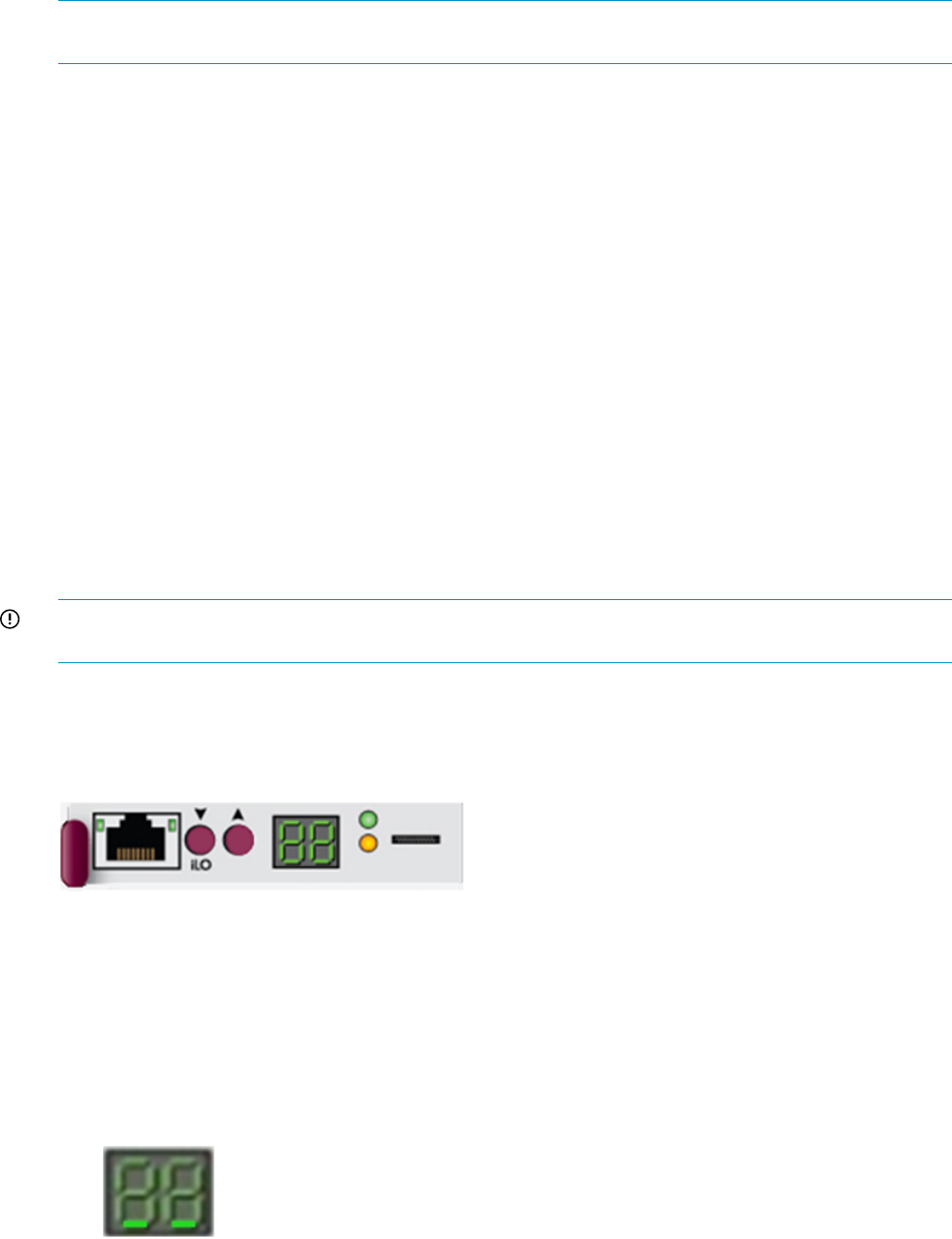
NOTE: Once the pause has begun, there is no way to continue the session before time runs out,
but you can always terminate the session (form the client end) and start another one.
Restrictions
<seconds> parameter can be any whole number from 1 to 86400.
HISTORY
Syntax
HISTORY
Description
Shows the history of commands for the current session.
Restrictions
None
Manual button functions
The primary interface to the Enclosure Manager is its Ethernet LAN port, which is intended for
remote management of the enclosure. AC power is applied to the enclosure so that aux power is
available to the EM. The enclosure may or may not be powered on. Solution software may or may
not be installed.
IMPORTANT: Use the following manual button functions only with the assistance of HP Technical
Support.
The two manual buttons and two-digit LED display on the EMU provide basic management functions
when the EM is not connected to the network. The figure below illustrates the physical (touch/visual)
interaction elements:
Figure 24 EM Physical Interface
Activate Button Menu
You cannot manage the EM using a remote management interface because the system is not
connected to the LAN, the LAN interface is not functioning properly, or management software is
not installed or available.
Procedure:
1. Press and hold the UP (left) button until the two digits display “- -“.
2. Release the UP button. System displays two underscores “_ _”:
This display indicates context is at the bottom of the menu range and is awaiting menu selection,
which requires pressing UP button one or more times.
Manual button functions 185
Reboot EM (bE)
The EM LAN interface is not responding to the remote management software but is configured to
do so, or the EM has just been reconfigured and needs to be rebooted for the configuration to
take effect.
Procedure:
1. Enter the menu mode by performing Activate Button Menu.
2. Press the UP button once.
The EM changes the display from “_ _“ to “bE” to indicate menu choice 0 (Reboot) is selected.
3. Press and hold the UP button down for 3 seconds.
The system blinks (or flashes) the 2 “bE” for one second to acknowledge the selection.
4. Release the UP button.
The system then reboots the EM. This event is logged in the system log. The display shows - -
during the reboot. Also the module fault LED flashes. When the reboot is complete, the EM
green health LED is lit steady and the enclosure ID is displayed on the two digits.
Restore Factory Defaults (Fd)
You may be replacing an EM or reconfiguring a messaging system.
Procedure:
1. Enter the menu mode by performing Activate Button Menu.
2. Press the UP button three times to select menu choice (Set Factory Defaults) so that the display
changes from “_ _“ to “Fd”.
3. Press and hold the UP button down for 3 seconds.
In response, the EM blinks (or flashes) the 2 “Fd” digits 3 times to acknowledge the selection.
4. Release the UP button.
The system stops flashing the pattern, internally restores all configurations to factory defaults,
and reboots the EM.
Recover Lost Password (Fp)
You changed the Administrator password from the one set by the factory and then lost or forgot
the new password.
Procedure:
1. Enter the menu mode by performing Button Menu.
2. Press the UP button four times to select menu choice (Recover Lost Password) so that the display
changes from “_ _“ to “Fp”.
3. Press and hold the UP button for 3 seconds.
In response, the EM blinks (or flashes) the 2 “Fp” digits to acknowledge the selection.
4. Release the UP button.
The system stops flashing the “Fp”. The system restores the Administrator password from
hardware and logs the event in the syslog. The system displays the Enclosure ID to indicate
that the operation is complete.
Set DHCP IP Address (dH)
You need to reconfigure the messaging system for a different network where IP address assignment
is handled dynamically.
Procedure:
1. Enter the menu mode by performing Activate Button Menu.
2. Press the UP button 5 times so that the display changes from “_ _“ to “dH” (Set DHCP Mode).
186 EMU reference
3. Press and hold down the UP button for 3 seconds.
The EM flashes the display “dH” to indicate acceptance of the command.
4. Release the UP button.
The system sets the EM to DHCP and exits the menu mode. This event is also logged in the
EM syslog and takes effect immediately. The system displays the Enclosure ID to indicate that
the operation is complete.
Set Link Local IP Address (LL)
You need to reconfigure the messaging system for a network where IP address assignment is static.
Procedure:
1. Enter the menu mode by performing Activate Button Menu.
2. Press the UP button six times so that the display changes from “_ _“ to “LL” (Set Link Local
Mode).
3. Press and hold down the UP button for 3 seconds.
The EM flashes the display “LL” acknowledging the operator’s request.
4. Release the UP button.
The system then sets the EM to Link Local mode and exits menu mode. The system also logs
this event in the EM syslog and the effect on network configuration is immediate. The system
displays the Enclosure ID to indicate that the operation is complete.
Display Current IP Address (IP)
You need to learn the IP address of the EM.
Procedure:
1. Enter the menu mode by performing Activate Button Menu.
2. Press the UP button six times so that the display changes from “_ _“ to “IP” (Display IP Address).
3. Press and hold the down UP button for 3 seconds.
The EM displays “IP” acknowledging the request.
4. Release the UP button.
System then enters the ‘Display IP’ sub function and displays the first octet of the IPv4 address
being used by the EM.
5. You may press the UP button 3 more times to scroll through the other 3 octets of the EM IP
address. You can backup using the DOWN button.
6. Press and hold the DOWN button for 3 seconds.
The EM flashes displays “IP” acknowledging the operator’s request and then exits the operation.
The system displays the Enclosure ID to indicate that the operation is complete.
Exit Button Menu
You want to exit the main menu (or any sub function).
Procedure: Press and hold the DOWN button for 3 seconds.
The system displays and flashes the two hyphens (“- -“) three times to indicate the menu was exited.
The system then returns the LEDs to their original display state showing the enclosure ID.
Manual button functions 187

B Regulatory compliance notices
This section contains regulatory notices for the HP ______________________.
Regulatory compliance identification numbers
For the purpose of regulatory compliance certifications and identification, this product has been
assigned a unique regulatory model number. The regulatory model number can be found on the
product nameplate label, along with all required approval markings and information. When
requesting compliance information for this product, always refer to this regulatory model number.
The regulatory model number is not the marketing name or model number of the product.
Product specific information:
HP ________________
Regulatory model number: _____________
FCC and CISPR classification: _____________
These products contain laser components. See Class 1 laser statement in the Laser compliance
notices section.
Federal Communications Commission notice
Part 15 of the Federal Communications Commission (FCC) Rules and Regulations has established
Radio Frequency (RF) emission limits to provide an interference-free radio frequency spectrum.
Many electronic devices, including computers, generate RF energy incidental to their intended
function and are, therefore, covered by these rules. These rules place computers and related
peripheral devices into two classes, A and B, depending upon their intended installation. Class A
devices are those that may reasonably be expected to be installed in a business or commercial
environment. Class B devices are those that may reasonably be expected to be installed in a
residential environment (for example, personal computers). The FCC requires devices in both classes
to bear a label indicating the interference potential of the device as well as additional operating
instructions for the user.
FCC rating label
The FCC rating label on the device shows the classification (A or B) of the equipment. Class B
devices have an FCC logo or ID on the label. Class A devices do not have an FCC logo or ID on
the label. After you determine the class of the device, refer to the corresponding statement.
Class A equipment
This equipment has been tested and found to comply with the limits for a Class A digital device,
pursuant to Part 15 of the FCC rules. These limits are designed to provide reasonable protection
against harmful interference when the equipment is operated in a commercial environment. This
equipment generates, uses, and can radiate radio frequency energy and, if not installed and used
in accordance with the instructions, may cause harmful interference to radio communications.
Operation of this equipment in a residential area is likely to cause harmful interference, in which
case the user must correct the interference at personal expense.
Class B equipment
This equipment has been tested and found to comply with the limits for a Class B digital device,
pursuant to Part 15 of the FCC Rules. These limits are designed to provide reasonable protection
against harmful interference in a residential installation. This equipment generates, uses, and can
radiate radio frequency energy and, if not installed and used in accordance with the instructions,
may cause harmful interference to radio communications. However, there is no guarantee that
interference does not occur in a particular installation. If this equipment does cause harmful
interference to radio or television reception, which can be determined by turning the equipment
188 Regulatory compliance notices
off and on, the user is encouraged to try to correct the interference by one or more of the following
measures:
•Reorient or relocate the receiving antenna.
•Increase the separation between the equipment and receiver.
•Connect the equipment into an outlet on a circuit that is different from that to which the receiver
is connected.
•Consult the dealer or an experienced radio or television technician for help.
Declaration of Conformity for products marked with the FCC logo, United States only
This device complies with Part 15 of the FCC Rules. Operation is subject to the following two
conditions: (1) this device may not cause harmful interference, and (2) this device must accept any
interference received, including interference that may cause undesired operation.
For questions regarding this FCC declaration, contact us by mail or telephone:
•Hewlett-Packard Company P.O. Box 692000, Mail Stop 510101 Houston, Texas 77269-2000
•Or call 1-281-514-3333
Modification
The FCC requires the user to be notified that any changes or modifications made to this device
that are not expressly approved by Hewlett-Packard Company may void the user's authority to
operate the equipment.
Cables
When provided, connections to this device must be made with shielded cables with metallic RFI/EMI
connector hoods in order to maintain compliance with FCC Rules and Regulations.
Canadian notice (Avis Canadien)
Class A equipment
This Class A digital apparatus meets all requirements of the Canadian Interference-Causing
Equipment Regulations.
Cet appareil numérique de la class A respecte toutes les exigences du Règlement sur le matériel
brouilleur du Canada.
Class B equipment
This Class B digital apparatus meets all requirements of the Canadian Interference-Causing
Equipment Regulations.
Cet appareil numérique de la class B respecte toutes les exigences du Règlement sur le matériel
brouilleur du Canada.
European Union notice
This product complies with the following EU directives:
•Low Voltage Directive 2006/95/EC
•EMC Directive 2004/108/EC
Compliance with these directives implies conformity to applicable harmonized European standards
(European Norms) which are listed on the EU Declaration of Conformity issued by Hewlett-Packard
for this product or product family.
Canadian notice (Avis Canadien) 189
This compliance is indicated by the following conformity marking placed on the product:
This marking is valid for non-Telecom products and EU
harmonized Telecom products (e.g., Bluetooth).
Certificates can be obtained from http://www.hp.com/go/certificates.
Hewlett-Packard GmbH, HQ-TRE, Herrenberger Strasse 140, 71034 Boeblingen, Germany
Japanese notices
Japanese VCCI-A notice
Japanese VCCI-B notice
Japanese VCCI marking
Japanese power cord statement
Korean notices
Class A equipment
190 Regulatory compliance notices
Class B equipment
Taiwanese notices
BSMI Class A notice
Taiwan battery recycle statement
Vietnamese notice
Taiwanese notices 191
Laser compliance notices
English laser notice
This device may contain a laser that is classified as a Class 1 Laser Product in accordance with
U.S. FDA regulations and the IEC 60825-1. The product does not emit hazardous laser radiation.
WARNING! Use of controls or adjustments or performance of procedures other than those
specified herein or in the laser product's installation guide may result in hazardous radiation
exposure. To reduce the risk of exposure to hazardous radiation:
•Do not try to open the module enclosure. There are no user-serviceable components inside.
•Do not operate controls, make adjustments, or perform procedures to the laser device other
than those specified herein.
•Allow only HP Authorized Service technicians to repair the unit.
The Center for Devices and Radiological Health (CDRH) of the U.S. Food and Drug Administration
implemented regulations for laser products on August 2, 1976. These regulations apply to laser
products manufactured from August 1, 1976. Compliance is mandatory for products marketed in
the United States.
Dutch laser notice
French laser notice
192 Regulatory compliance notices
German laser notice
Italian laser notice
Japanese laser notice
Laser compliance notices 193
Spanish laser notice
Recycling notices
English recycling notice
Disposal of waste equipment by users in private household in the European Union
This symbol means do not dispose of your product with your other household waste. Instead, you should
protect human health and the environment by handing over your waste equipment to a designated
collection point for the recycling of waste electrical and electronic equipment. For more information,
please contact your household waste disposal service
194 Regulatory compliance notices

Bulgarian recycling notice
Изхвърляне на отпадъчно оборудване от потребители в частни домакинства в Европейския
съюз
Този символ върху продукта или опаковката му показва, че продуктът не трябва да се изхвърля заедно
с другите битови отпадъци. Вместо това, трябва да предпазите човешкото здраве и околната среда,
като предадете отпадъчното оборудване в предназначен за събирането му пункт за рециклиране на
неизползваемо електрическо и електронно борудване. За допълнителна информация се свържете с
фирмата по чистота, чиито услуги използвате.
Czech recycling notice
Likvidace zařízení v domácnostech v Evropské unii
Tento symbol znamená, že nesmíte tento produkt likvidovat spolu s jiným domovním odpadem. Místo
toho byste měli chránit lidské zdraví a životní prostředí tím, že jej předáte na k tomu určené sběrné
pracoviště, kde se zabývají recyklací elektrického a elektronického vybavení. Pro více informací kontaktujte
společnost zabývající se sběrem a svozem domovního odpadu.
Danish recycling notice
Bortskaffelse af brugt udstyr hos brugere i private hjem i EU
Dette symbol betyder, at produktet ikke må bortskaffes sammen med andet husholdningsaffald. Du skal
i stedet den menneskelige sundhed og miljøet ved at afl evere dit brugte udstyr på et dertil beregnet
indsamlingssted for af brugt, elektrisk og elektronisk udstyr. Kontakt nærmeste renovationsafdeling for
yderligere oplysninger.
Dutch recycling notice
Inzameling van afgedankte apparatuur van particuliere huishoudens in de Europese Unie
Dit symbool betekent dat het product niet mag worden gedeponeerd bij het overige huishoudelijke afval.
Bescherm de gezondheid en het milieu door afgedankte apparatuur in te leveren bij een hiervoor bestemd
inzamelpunt voor recycling van afgedankte elektrische en elektronische apparatuur. Neem voor meer
informatie contact op met uw gemeentereinigingsdienst.
Recycling notices 195

Estonian recycling notice
Äravisatavate seadmete likvideerimine Euroopa Liidu eramajapidamistes
See märk näitab, et seadet ei tohi visata olmeprügi hulka. Inimeste tervise ja keskkonna säästmise nimel
tuleb äravisatav toode tuua elektriliste ja elektrooniliste seadmete käitlemisega egelevasse kogumispunkti.
Küsimuste korral pöörduge kohaliku prügikäitlusettevõtte poole.
Finnish recycling notice
Kotitalousjätteiden hävittäminen Euroopan unionin alueella
Tämä symboli merkitsee, että laitetta ei saa hävittää muiden kotitalousjätteiden mukana. Sen sijaan sinun
on suojattava ihmisten terveyttä ja ympäristöä toimittamalla käytöstä poistettu laite sähkö- tai
elektroniikkajätteen kierrätyspisteeseen. Lisätietoja saat jätehuoltoyhtiöltä.
French recycling notice
Mise au rebut d'équipement par les utilisateurs privés dans l'Union Européenne
Ce symbole indique que vous ne devez pas jeter votre produit avec les ordures ménagères. Il est de
votre responsabilité de protéger la santé et l'environnement et de vous débarrasser de votre équipement
en le remettant à une déchetterie effectuant le recyclage des équipements électriques et électroniques.
Pour de plus amples informations, prenez contact avec votre service d'élimination des ordures ménagères.
German recycling notice
Entsorgung von Altgeräten von Benutzern in privaten Haushalten in der EU
Dieses Symbol besagt, dass dieses Produkt nicht mit dem Haushaltsmüll entsorgt werden darf. Zum
Schutze der Gesundheit und der Umwelt sollten Sie stattdessen Ihre Altgeräte zur Entsorgung einer dafür
vorgesehenen Recyclingstelle für elektrische und elektronische Geräte übergeben. Weitere Informationen
erhalten Sie von Ihrem Entsorgungsunternehmen für Hausmüll.
196 Regulatory compliance notices

Greek recycling notice
Απόρριψη άχρηοτου εξοπλισμού από ιδιώτες χρήστες στην Ευρωπαϊκή Ένωση
Αυτό το σύμβολο σημαίνει ότι δεν πρέπει να απορρίψετε το προϊόν με τα λοιπά οικιακά απορρίμματα.
Αντίθετα, πρέπει να προστατέψετε την ανθρώπινη υγεία και το περιβάλλον παραδίδοντας τον άχρηστο
εξοπλισμό σας σε εξουσιοδοτημένο σημείο συλλογής για την ανακύκλωση άχρηστου ηλεκτρικού και
ηλεκτρονικού εξοπλισμού. Για περισσότερες πληροφορίες, επικοινωνήστε με την υπηρεσία απόρριψης
απορριμμάτων της περιοχής σας.
Hungarian recycling notice
A hulladék anyagok megsemmisítése az Európai Unió háztartásaiban
Ez a szimbólum azt jelzi, hogy a készüléket nem szabad a háztartási hulladékkal együtt kidobni. Ehelyett
a leselejtezett berendezéseknek az elektromos vagy elektronikus hulladék átvételére kijelölt helyen történő
beszolgáltatásával megóvja az emberi egészséget és a környezetet.További információt a helyi
köztisztasági vállalattól kaphat.
Italian recycling notice
Smaltimento di apparecchiature usate da parte di utenti privati nell'Unione Europea
Questo simbolo avvisa di non smaltire il prodotto con i normali rifi uti domestici. Rispettare la salute
umana e l'ambiente conferendo l'apparecchiatura dismessa a un centro di raccolta designato per il
riciclo di apparecchiature elettroniche ed elettriche. Per ulteriori informazioni, rivolgersi al servizio per
lo smaltimento dei rifi uti domestici.
Latvian recycling notice
Europos Sąjungos namų ūkio vartotojų įrangos atliekų šalinimas
Šis simbolis nurodo, kad gaminio negalima išmesti kartu su kitomis buitinėmis atliekomis. Kad
apsaugotumėte žmonių sveikatą ir aplinką, pasenusią nenaudojamą įrangą turite nuvežti į elektrinių ir
elektroninių atliekų surinkimo punktą. Daugiau informacijos teiraukitės buitinių atliekų surinkimo tarnybos.
Recycling notices 197

Lithuanian recycling notice
Nolietotu iekārtu iznīcināšanas noteikumi lietotājiem Eiropas Savienības privātajās mājsaimniecībās
Šis simbols norāda, ka ierīci nedrīkst utilizēt kopā ar citiem mājsaimniecības atkritumiem. Jums jārūpējas
par cilvēku veselības un vides aizsardzību, nododot lietoto aprīkojumu otrreizējai pārstrādei īpašā lietotu
elektrisko un elektronisko ierīču savākšanas punktā. Lai iegūtu plašāku informāciju, lūdzu, sazinieties ar
savu mājsaimniecības atkritumu likvidēšanas dienestu.
Polish recycling notice
Utylizacja zużytego sprzętu przez użytkowników w prywatnych gospodarstwach domowych w
krajach Unii Europejskiej
Ten symbol oznacza, że nie wolno wyrzucać produktu wraz z innymi domowymi odpadkami.
Obowiązkiem użytkownika jest ochrona zdrowa ludzkiego i środowiska przez przekazanie zużytego
sprzętu do wyznaczonego punktu zajmującego się recyklingiem odpadów powstałych ze sprzętu
elektrycznego i elektronicznego. Więcej informacji można uzyskać od lokalnej firmy zajmującej wywozem
nieczystości.
Portuguese recycling notice
Descarte de equipamentos usados por utilizadores domésticos na União Europeia
Este símbolo indica que não deve descartar o seu produto juntamente com os outros lixos domiciliares.
Ao invés disso, deve proteger a saúde humana e o meio ambiente levando o seu equipamento para
descarte em um ponto de recolha destinado à reciclagem de resíduos de equipamentos eléctricos e
electrónicos. Para obter mais informações, contacte o seu serviço de tratamento de resíduos domésticos.
Romanian recycling notice
Casarea echipamentului uzat de către utilizatorii casnici din Uniunea Europeană
Acest simbol înseamnă să nu se arunce produsul cu alte deşeuri menajere. În schimb, trebuie să protejaţi
sănătatea umană şi mediul predând echipamentul uzat la un punct de colectare desemnat pentru reciclarea
echipamentelor electrice şi electronice uzate. Pentru informaţii suplimentare, vă rugăm să contactaţi
serviciul de eliminare a deşeurilor menajere local.
198 Regulatory compliance notices

Slovak recycling notice
Likvidácia vyradených zariadení používateľmi v domácnostiach v Európskej únii
Tento symbol znamená, že tento produkt sa nemá likvidovať s ostatným domovým odpadom. Namiesto
toho by ste mali chrániť ľudské zdravie a životné prostredie odovzdaním odpadového zariadenia na
zbernom mieste, ktoré je určené na recykláciu odpadových elektrických a elektronických zariadení.
Ďalšie informácie získate od spoločnosti zaoberajúcej sa likvidáciou domového odpadu.
Spanish recycling notice
Eliminación de los equipos que ya no se utilizan en entornos domésticos de la Unión Europea
Este símbolo indica que este producto no debe eliminarse con los residuos domésticos. En lugar de ello,
debe evitar causar daños a la salud de las personas y al medio ambiente llevando los equipos que no
utilice a un punto de recogida designado para el reciclaje de equipos eléctricos y electrónicos que ya
no se utilizan. Para obtener más información, póngase en contacto con el servicio de recogida de
residuos domésticos.
Swedish recycling notice
Hantering av elektroniskt avfall för hemanvändare inom EU
Den här symbolen innebär att du inte ska kasta din produkt i hushållsavfallet. Värna i stället om natur
och miljö genom att lämna in uttjänt utrustning på anvisad insamlingsplats. Allt elektriskt och elektroniskt
avfall går sedan vidare till återvinning. Kontakta ditt återvinningsföretag för mer information.
Turkish recycling notice
Türkiye Cumhuriyeti: EEE Yönetmeliğine Uygundur
Recycling notices 199
Battery replacement notices
Dutch battery notice
French battery notice
200 Regulatory compliance notices
German battery notice
Italian battery notice
Battery replacement notices 201
Japanese battery notice
Spanish battery notice
202 Regulatory compliance notices

Glossary
CAS Client Access Server. The Client Access server role is one of five distinct server roles for Microsoft
Exchange Server 2010. It supports the Outlook Web App and Microsoft Exchange ActiveSync
client applications, and the Post Office Protocol version 3 (POP3) and Internet Message Access
Protocol version 4rev1 (IMAP4) protocols. The Client Access server role also provides access to
free/busy data by using the Availability service and enables certain clients to download automatic
configuration settings from the Autodiscover service. For more information, see the Microsoft
Technet article, Understanding Client Access at
nl
http://technet.microsoft.com/en-us/library/bb124915.aspx.
DAG Database Availability Group. A database availability group is the base component of the high
availability and site resilience framework built into Microsoft Exchange Server 2010. A DAG is
a group of up to 16 Mailbox servers that hosts a set of databases and provides automatic
database-level recovery from failures that affect individual servers or databases. For more
information, see the Microsoft Technet article, Understanding Database Availability Groups at
nl
http://technet.microsoft.com/en-us/library/dd979799.aspx.
OWA Outlook Web Access. The Web browser-based version of Microsoft Outlook. Formerly called
"Exchange Web Connect" (EWC), Outlook Web Access (OWA) is provided by Exchange Server
and enables users on the road to access their email, contacts and calendar from any Web browser
without having to run a pre-configured Outlook client program.
UFM Voltaire's Unified Fabric Manager client software.
Witness Server A server used for high availability in conjunction with Database Availability Groups. For more
information, see the Microsoft Technet article, Create a Database Availability Group at
nl
http://technet.microsoft.com/en-us/library/dd351172.aspx.
WWN Worldwide name.
WWPN World wide port name. A unique 64-bit address used in a FC storage network to identify each
device in a FC network.
203

Index
Symbols
2-port 1Gb Ethernet I/O module
LED behavior, 56
2-port 1Gb Mezz A and B I/O module
LED behavior, 56
B
battery replacement notices, 200
best practices
for removing and replacing hardware components, 69
Best Practices Analyzer
running, 34
C
cache module controller
LED behavior, 54
Canadian notice, 189
capacitor pack
removing and replacing, 144
chassis switches
LED behavior, 57
component replacement videos
accessing, 69
Configuration Wizard see E5000 Messaging System
contacting HP, 150
controller and controller server blade components
removing and replacing, 139
conventions
text symbols, 152
customer self repair see removing and replacing hardware
components
D
Declaration of Conformity, 189
Disposal of waste equipment, European Union, 194
drive drawer
removing and replacing, 118
drive drawer hard drive
removing and replacing, 124
drive drawer rails (side or bottom)
removing and replacing, 126
drive fan
LED behavior, 58
removing and replacing, 84
E
E5000 Messaging System
accessing, 21
adding expansion nodes, 22
Configuration Wizard, 24
configuring system software, 24
exploded view, 70
features, 7
front view, 7
hardware models, 7
installing hardware, 14
installing software updates, 63
kit contents, 14
locating product number, 14
locating SAID number, 14
locating serial number, 14
monitoring tools, 37
powering off, 63
powering on, 17
preparing to install, 9
rear view, 7
recovery, 147
restoring factory image, 147
troubleshooting tools, 37
unpacking, 15
update file, 63
updating system software and firmware, 63
E5000 System Manager
description, 43
Exchange Status tab, 45
Firmware tab, 46
Hardware Status tab, 44
Reports tab, 47
System Summary tab, 44
E5300 hardware model
adding hard drives, 23
connection options, 11
network configuration, 10
E5500/E5700 hardware model
EMU connection options, 13
network configuration, 12
electrostatic discharge
avoiding, 73
EMU
CLI reference, 153
configuring management processor, 17
connection options for E5300 hardware model, 11
connection options for E5500/E5700 hardware model,
13
LED behavior, 55
logging in, 59
network connections, 9
network port locations, 9
removing and replacing, 97
using CLI SHOW commands for troubleshooting, 59
Enclosure Manager Unit (EMU) see EMU
enclosure rails
removing and replacing, 132
Ethernet I/O module
removing and replacing, 90
European Union notice, 189
Event Notifier
configuring for proemail (SMTP) event notification, 39
Exchange Deployment Tool
Microsoft Exchange Server 2010, 30
expansion node
204 Index
adding to installed E5000 Messaging System, 22
installing hardware and cabling, 16
F
factory image
restoring the system, 147
failure of component
verifying, 73
Federal Communications Commission notice, 188
firmware
checking for version upgrade, 46, 65
updating component, 64
front bezel (full)
removing and replacing, 108
front bezel (standard)
removing and replacing, 106
front LED display board
LED behavior, 52
front LED display board (full)
removing and replacing, 114
front LED display board in the rack (standard)
removing and replacing, 111
H
hard drive
adding to E5300 hardware model, 23
LED behavior, 54
wait time after replacement, 74
HP E5000 Configuration Wizard
Configuration Wizard, 24
I
I/O module
LED behavior, 58
iLO
configuring management processor, 17
Insight Remote Support, 60
implementing, 61
installing E5000 Messaging System hardware, 14
J
Japanese notices, 190
Jetstress see Microsoft Exchange Jetstress and Load
Generator
K
kit contents
E5000 Messaging System, 14
Korean notices, 190
L
laser compliance notices, 192
LED
2-port 1 Gb Ethernet I/O module, 56
2-port 1 Gb Ethernet, Mezz A and B I/O module, 56
cache module controller, 54
chassis switches and indicator, 57
EMU, 55
fan, 58
front LED display board, 52
hard drive, 54
I/O module, 58
power supply, 57
server blade, 51
Load Generator see Microsoft Exchange Jetstress and Load
Generator
M
maintenance
SAID, 61
warranty entitlement labels, 62
management processor
configuring EMU, 17
configuring iLO, 17
Mezzanine NIC
removing and replacing, 92
Microsoft Exchange Jetstress and Load Generator, 35
Microsoft Exchange Server 2010
deploying, 30
Exchange Deployment Tool, 30
network requirements, 9
Microsoft Systems Center Operations Manager (SCOM)
using for monitoring and troubleshooting, 61
midplane board
removing and replacing, 77
monitoring tools, 37
component LEDs, 51
E5000 System Manager, 43
EMU CLI SHOW commands, 59
Event Notifer, 39
Microsoft Systems Center Operations Manager (SCOM),
61
notification alerts, 37
System Management Homepage, 48
N
network configuration
E5300 hardware model, 10
E5500/E5700 hardware model, 12
network connections
EMU, 9
network requirements
Microsoft Exchange Server 2010, 9
notification alerts, 37
sample error messages, 37
O
OpsMgr see Microsoft Systems Center Operations
Manager (SCOM)
P
P1210m cache module
removing and replacing, 141
PCIe module
removing and replacing, 95
power off procedure, 63
power on procedure, 17, 63
power supply
205
LED behavior, 57
removing and replacing, 90
power UID button assembly
removing and replacing, 87
product number
locating , 14
R
rack rails
removing and replacing, 137
Rack stability
HP, 152
recovering the system, 147
system recovery DVD, 147
USB flash drive, 147
recycling notices, 194
regulatory compliance
Canadian notice, 189
European Union notice, 189
identification numbers, 188
Japanese notices, 190
Korean notices, 190
laser, 192
recycling notices, 194
Taiwanese notices, 191
Vietnamese notice, 191
remote support see Insight Remote Support
removing and replacing hardware components, 69
best practices, 69
capacitor pack, 144
controller and controller server blade components, 139
drive drawer, 118
drive drawer hard drive, 124
drive drawer rails (side or bottom), 126
drive fan, 84
EMU, 97
enclosure rails, 132
Ethernet I/O module, 90
front bezel (full), 108
front bezel (standard), 106
front LED display board (full), 114
front LED display board in the rack (standard), 111
Mezzanine NIC, 92
midplane board, 77
P1210m cache module, 141
PCIe module, 95
power supply, 90
power UID button assembly, 87
rack rails, 137
SAS cable, 82
SAS I/O module, 83
server airflow baffle, 103
server blade, 137
server blade backplane, 98
server blade hard drive, 138
server fan module, 86
server interposter board, 74
replaceable part
identifying, 70
restoring the system
factory image, 147
in non-production environments, 148
in production environments, 149
managing disks after restoration, 148
S
SAID
locating number, 14
obtaining, 61
SAS cable
removing and replacing, 82
SAS I/O module
removing and replacing, 83
serial number
locating, 14
server airflow baffle
removing and replacing, 103
server blade
LED behavior, 51
removing and replacing, 137
server blade backplane
removing and replacing, 98
server blade hard drive
removing and replacing, 138
server fan module
removing and replacing, 86
server interposter board
removing and replacing, 74
Service Agreement ID see SAID
spare part
hot, warm, cold swap, 73
identifying, 69
verifying proper operation after replacement, 74
Subscriber's Choice for Business, 150
Support websites
contacting HP, 150
HP, 60, 150
Microsoft, 151
Subscribers's Choice for Business, 150
Subscription service, 150
system fan
LED behavior, 58
System Management Homepage
description, 48
Help menu, 48
main page, 49
starting, 49
Storage System page, 50
system recovery
DVD, 147
USB flash drive, 147, 148
system software
updating, 63
T
Taiwanese notices, 191
technical support see Support websites
troubleshooting tools, 37
206 Index
component LEDs, 51
E5000 System Manager, 43
EMU CLI SHOW commands, 59
Event Notifer, 39
Insight Remote Support, 60
Microsoft Systems Center Operations Manager (SCOM),
61
notification alerts, 37
System Management Homepage, 48
U
unpacking the E5000 Messaging System, 15
updating
system software and firmware, 63
updating messaging system software
,63
USB flash drive
system recovery, 148
V
Vietnamese notice, 191
W
warranty entitlement labels
locations, 62
207
