Hp Elitedesk 800 G1 Desktop Mini Pc Reference Guide Creatures_800_IPSM
2015-01-05
: Hp Hp-Elitedesk-800-G1-Desktop-Mini-Pc-Reference-Guide-147827 hp-elitedesk-800-g1-desktop-mini-pc-reference-guide-147827 hp pdf
Open the PDF directly: View PDF ![]() .
.
Page Count: 4
HP EliteDesk 800 G1 Desktop Mini 756962-001 page 1
Illustrated parts & service map
HP EliteDesk 800 G1 Desktop Mini
© 2014 Hewlett-Packard Development Company, L.P. The information con-
tained herein is subject to change without notice. HP shall not be liable for
technical or editorial errors or omissions contained herein.
Document Number 756962-001. 1st Edition May 2014.
Key specifications
Spare parts
System unit
Miscellaneous parts
Processor type Intel® Celeron, Pentium® and 4th Generation Core™ i3, i5 and
i7 processors
RAM type
1600 MHz, DDR3 SDRAM, SODIMM, 2 slots
Maximum RAM 16 GB
Expansion slots (1) internal M.2 connector for optional wireless NIC module
(1) internal M.2 connector for optional SSD drive
Chipset Intel Q87
Bays (1) 2.5” internal storage drive bay
I/O interfaces Front: 3.5 mm headphone output and microphone jacks; (2)
USB 3.0 ports; (1) port with Fast Charge technology
Rear: (4) USB 3.0 ports; (1) VGA video port; (2) DisplayPort
with multistream video ports; (1) RJ-45 network connector;
3.5 mm audio out jack
Internal storage 500TB SATA hard drive; up to 1TB solid state hybrid drive; up
to 256GB Opal self-encrypting solid state drive
Operating systems • Windows 8.1
• Windows 7
•FreeDOS
• Novell SUSE Linux Enterprise Desktop 11
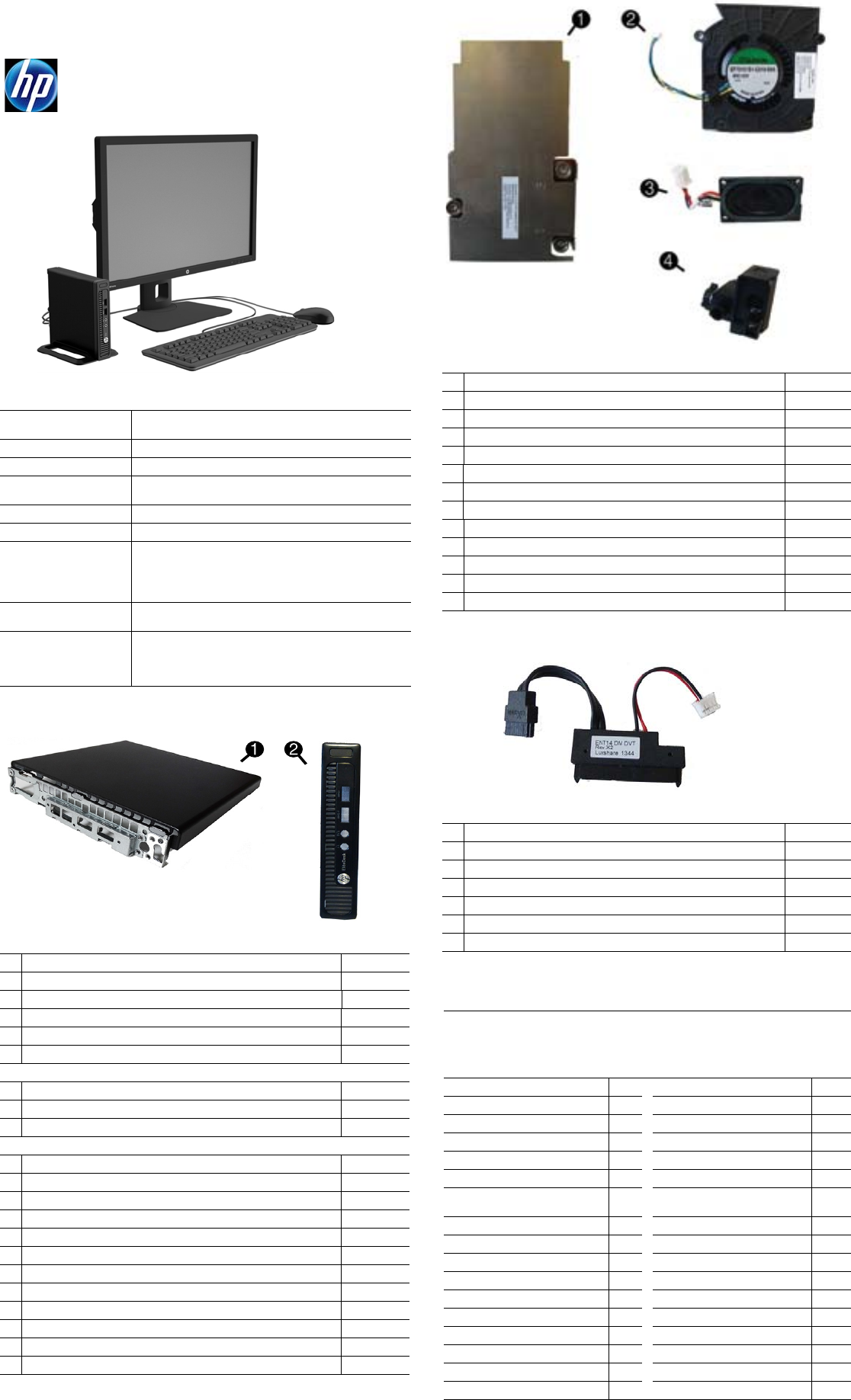
System unit
1 Access panel 768428-001
2 Front bezel 768422-001
* Stand assembly 768430-001
* Power supply, 65W 751889-001
* 8-GB memory module (PC3-12800, SODIMM) 689374-001
* 4-GB memory module (PC3-12800, SODIMM) 689373-001
System boards (include thermal material; callouts illustrated on last page)
* System board for use in models without Windows 8 746632-001
* System board for use in models with Windows Standard 746632-501
* System board for use in models with Windows Professional 746632-601
Processors (include thermal material)
* Intel Core i7-4785T, 2.2 GHz, 8-MB L3 cache 773230-001
* Intel Core i7-4765T, 2.0 GHz, 8-MB L3 cache 754000-001
* Intel Core i5-4590T, 2.0 GHz, 6-MB L3 cache 773228-001
* Intel Core i5-4570T, 2.9 GHz, 4-MB L3 cache 753998-001
* Intel Core i3-4330T, 3.0 GHz, 4-MB L3 cache 753995-001
* Intel Core i3-4130T, 2.9 GHz, 3-MB L3 cache 757416-001
* Intel Pentium G3440T 2.8-GHz, 3 MB cache 773233-001
* Intel Pentium G3420T 2.7-GHz, 3 MB cache 763217-001
* Intel Pentium G3240T 2.7-GHz, 3 MB cache 773232-001
* Intel Pentium G3220T 2.6-GHz, 3 MB cache 763216-001
* Intel Celeron G1840T processor (2.5-GHz, 3 MB cache) 773225-001
* Intel Celeron G1820T processor (2.4-GHz, 3 MB cache) 753994-001
*Not shown
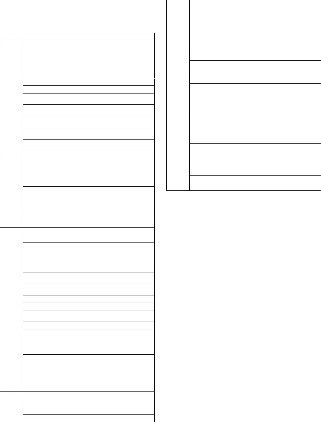
Miscellaneous parts
1 Heat sink (thermal module) 768426-001
2 Fan 768424-001
3 Speaker 762420-001
4 LED cover 768425-001
* Hood sensor assembly 768429-001
* Wireless LAN module, 802.11 a/b/g/n 2x2 768423-001
* Wireless LAN module, 802.11 a/b/g/n 2x2, for use in Indonesia 750552-001
* Antenna cover 768433-001
* HP Ultraslim keyed cable lock 703372-001
* Mouse, wireless 674317-001
* Mouse, USB, optical 674316-001
* Mouse, USB, laser 674318-001
* Mouse, washable 724795-001
*Not shown
Cables
1 SATA power cable 768427-001
* Wireless antenna cables, internal 768432-001
* Adapter, DisplayPort to VGA 632484-001
* Adapter, DisplayPort to DVI 662723-001
* Adapter, DisplayPort to HDMI 617450-001
* DisplayPort cable 487562-001
* USB to serial converter 407185-001
*Not shown
Keyboards (not illustrated)
USB
Wireless keyboard with dongle (Brazil)
Wireless with mouse and dongle
Washable
Smart card, CCID
724720-xx1
724722-201
730323-xx1
700510-xx1
701671-xx1
Arabic -17x Japanese -29x
F Arabic -DEx LA Spanish -16x
BHCSY -B4x Norwegian -09x
Belgian -18x People’s Republic of China
-AAx
Brazilian Portuguese -20x Portuguese -13x
Bulgaria -26x Romanian -27x
Czech and Slovakian
Czech
-CG1
-22x
Russian -25x
Danish -08x Slovenian -23x
French -05x South Korea -KDx
French Canadian -12x Spanish -07x
German -04x Swedish -10x
Greek -15x Swiss -11x
Hebrew -BBx Taiwanese -ABx
Hungarian -21x Thai -28x
India -D6x Turkish -14x
International English -L3x U.S. -00x
Italian -06x U.K. -03x

HP EliteDesk 800 G1 Desktop Mini 756962-001 page 2
Password security
Establishing a Setup or Power-On password:
1. Turn on or restart the computer.
2. As soon as the computer turns on, press the Esc key while “Press the ESC key for Startup
Menu” message is displayed at the bottom of the screen.
3. Press the F10 key to enter Computer Setup.
4. To establish Setup password, select Security > Setup Password and follow the
instructions.
- or -
To establish a Power-On password, select Security > Power-On Password and follow the
instructions on the screen
5. Before exiting, click File > Save Changes and Exit.
Changing a Setup or Power-On password:
1. Turn on or restart the computer.
To change the Setup password, go to step 2.
To change the Power-on password, go to step 3.
2. To change the Setup password, as soon as the computer turns on:
- Press the Esc key while “Press the ESC key for Startup Menu” message is displayed.
- Press the F10 key to enter Computer Setup.
3. When the key icon appears, type your current password, a slash (/) or alternate delimiter
character, your new password, another slash (/) or alternate delimiter character, and your
new password again as shown:
current password/new password/new password.
NOTE: Type the new password carefully since the characters do not appear on the screen.
4. Press Enter.
The new password will take effect the next time the computer is restarted.
Deleting a Power-On or Setup password
1. Turn on or restart the computer.
To delete the Setup password, go to step 2.
To delete the Power-On password, go to step 3.
2. To change the Setup password, as soon as the computer turns on:
- Press the Esc key while “Press the ESC key for Startup Menu” message is displayed.
- Press the F10 key to enter Computer Setup.
3. When the key icon appears, type your current password followed by a slash (/) or alternate
delimiter character as shown. Example: currentpassword/
4. Press Enter.
Clearing CMOS
1. Turn off the computer and disconnect the power cord from the power outlet.
2. Remove the access panel.
3. On the system board, press and hold the CMOS button for 5 seconds.
4. Replace the chassis access panel and reconnect the power cord.
5. Turn on the computer and allow it to start.
Mass storage devices (not illustrated)
1 TB hard drive, 2.5-inch, hybrid SSD, self-encrypting (SED) 724937-001
500 GB, 7200 rpm hard drive, 2.5-inch, self-encrypting (SED) 745136-001
500 GB, 7200 rpm hard drive, 2.5-inch 745135-001
500 GB hard drive, 2.5-inch, hybrid SSD, self-encrypting (SED) 724938-001
256 GB Solid State Drive (SSD), self-encrypting (SED) 746141-001
180 GB Solid State Drive (SSD), MLC 754076-001
128 GB Solid State Drive (SSD), self-encrypting (SED) 746140-001
128 GB Solid State Drive (SSD), M.2 757990-001
120 GB Solid State Drive (SSD), MLC 756459-001
Diagnostic LEDs
LED Color LED Activity State/Message
Power White On Computer on
Power White 1 blink every 2 seconds Normal Suspend Mode
Power Red 2 blinks every second fol-
lowed by a 2 second pause
CPU thermal shutdown
Power Red 3 blinks, 1 blink every second
followed by a 2 second pause
Processor not installed
Power Red 4 blinks, 1 blink every second
followed by a 2 second pause
Power failure (power supply over-
load)
Power Red 5 blinks, 1 blink every second
followed by a 2 second pause
Pre-video memory error
Power Red 6 blinks, 1 blink every second
followed by a 2 second pause
Pre-video graphics error
Power Red 7 blinks, 1 blink every second
followed by a 2 second pause
System board failure (ROM)
Power Red 8 blinks, 1 blink every second
followed by a 2 second pause
Invalid ROM based on Checksum
Power Red 9 blinks, 1 blink every second
followed by a 2 second pause
System powers on but is unable to
boot
Power Red 10 blinks, 1 blink every second
followed by a 2 second pause
Bad option card
Power Red 11 blinks, 1 blink every second
followed by a 2 second pause
Current processor does not support a
feature previously enabled.
none none System does not power on
and LEDs are not flashing
System unable to power on
Common POST error messages
Screen message Probable cause Recommended action
101-Option ROM Error System ROM checksum
error.
1. Verify ROM, reflash if required
2. Clear CMOS memory, reboot
3. Replace system board
103-System Board
Failure
DMA, timers 1. Clear CMOS memory.
2. Replace system board.
164-Memory Size Error
and
201-Memory Error
Incorrect memory configu-
ration
1. Run Setup (F10).
2. Check DIMMs for proper
seating, type, compatibility.
3. Remove DIMMs singularly and
reboot to isolate faulty DIMM.
4. Replace system board.
213-Incompatible Mem-
ory Module in Memory
Socket(s) X,X, ...
A memory module in mem-
ory socket identified in the
error message is missing
critical SPD information, or
is incompatible with the
chipset.
1. Verify proper memory module
type.
2. Try another memory socket.
3. Replace DIMM with a module
conforming to the SPD standard.
214-DIMM Configuration
Warning
Populated DIMM configura-
tion is not optimized
1. Check DIMMs for proper
seating, type, compatibility.
2. Rearrange the DIMMs so that
each channel has the same
amount of memory.
219-ECC Memory Module
Detected ECC Modules not
supported on this Plat-
form
Recently added memory
module(s) support ECC
memory error correction.
If additional memory was recently
added, remove it to see if the
problem remains.
301-, 304-Keyboard error Keyboard failure. Check kybd connection or keys.
Check connector for bent or miss-
ing pins. Replace kybd. If 304,
possible system board problem.
510-Flash Screen
Image Corrupted
Flash Screen image has
errors.
Reflash the system ROM with the
latest BIOS image.
912-Computer Cover Has
Been Removed Since Last
System Startup
Computer cover was
removed since last system
startup.
No action required.
1720-SMART Hard Drive
Detects Imminent Failure
Hard drive is about to fail.
1. Determine if hard drive is giving
correct error message. Use F2
Diagnostics to run DPS Self-test.
2. Apply hard drive firmware
patch if applicable.
3. Back up contents and replace
hard drive.
1796-SATA Cabling Error One or more SATA devices
are improperly attached. For
optimal performance, the
SATA 0 and SATA 1 connec-
tors must be used before
SATA 2 and SATA 3.
Ensure SATA connectors are used
in ascending order. For one
device, use SATA 0. For two
devices, use SATA 0 and SATA 1.
For three devices, use SATA 0,
SATA1, and SATA 2.
1801-Microcode Patch
Error
Processor not supported by
ROM BIOS.
1. Upgrade BIOS to proper
version.
2. Change the processor.
Invalid Electronic Serial
Number
Electronic serial number is
missing.
Enter the correct serial number in
Computer Setup.
HP EliteDesk 800 G1 Desktop Mini 756962-001 page 3
System setup and boot
Access the Setup Utility during computer boot by pressing the F10 key. If you do not press F10
at the appropriate time, you must restart the computer and again press F10 when the monitor
light turns green. NOTE: Not all settings are available for all models.
Computer Setup Menu
Heading Option/Description
File System Information - Lists the following main system specifications:
•Product name
• Manufacturer
• SKU number
• Processor type/speed/stepping
• Installed memory size/speed/ch
• Integrated MAC Address
• Chassis serial number
• Asset tracking number
•System board ID
• System board CT Number
•BIOS
About - Displays copyright notice.
Set Time and Date - Allows you to set system time and date.
Flash System ROM - Allows you to update the system ROM with a BIOS image
file located on removable media.
Replicated Setup - Allows you to save or restore system configuration to/
from a USB flash drive.
Default Setup - Allows you to save current settings as default or restore fac-
tory settings as default.
Apply Defaults and Exit - Applies the selected default settings and clears any
established passwords.
Ignore Changes and Exit - Exits Computer setup without saving changes.
Save Changes and Exit - Saves changes to system configuration or default
settings and exits Computer Setup.
Storage Device Configuration - Lists all installed BIOS-controlled storage devices. The
following options are available:
•CD-ROM
•Hard Disk
•Diskette (external USB)
Storage Options - Allows you to set:
• SATA Emulation - Choose how the SATA controller and devices are accessed
by the OS. SATA Emulation choices are AHCI or IDE.
• Removable Media Boot - Enables/disables ability to boot the system from
removable media.
Boot Order - Specify boot order for UEFI and legacy boot sources. Also specify
hard drive boot order.
• Shortcut to Temporarily Override Boot Order
Security
Setup Password - Set and enable the setup (Admin) password.
Power-On Password - Set and enable power-on password.
Password Options - Allows to you enable/disable:
•Lock Legacy Resources
• Setup Browse Mode
• Password prompt on F9 & F12
• Network Server Mode
•Stringent Password
Device Security - Set Device Available/Device Hidden for: system audio, network con-
troller, and SATA ports.
USB Security - Set Device Available/Device Hidden for front USB ports, rear USB
ports, accessory USB ports.
Slot Security - Disable any PCIe slots.
Network Boot - Enables/disables boot from OS (NIC models only).
System IDs - Allows you to update asset tag, ownership tag, UUID, keyboard
locale setting.
Master Boot Record Security - enables/disables MBR.
System Security - Allows you to set:
• Data Execution Prevention (enable/disable)
• Virtualization Technology (VTx) (enable/disable)
• Embedded Security Device (enable/disable)
• OS management of Embedded Security Device
DriveLock Security - Allows you to assign or modify a master or user password
for hard drives.
Secure Boot Configuration (Windows 8 only)
• Legacy Support (enable/disable)
• Secure Boot (enable/disable).
• Key Management (enable/disable)
• Fast Boot (enable/disable)
Power OS Power Management - Allows you to enable/disable Runtime Power Man-
agement, Idle Power Savings.
Hardware Power Management - Enable/disable SATA power management, S5 maxi-
mum power savings., PCI slots, network controller, USB 3.0 controller
Thermal - Control minimum fan speed.
Advanced
Power-On Options - Allows you to set:
• POST mode (QuickBoot, Clear Memory, FullBoot, or FullBoot Every x Days)
• POST messages (enable/disable)
• Press the ESC key for Startup Menu (enable/disable)
• Option ROM Prompt (enable/disable)
• After Power Loss (off/on/previous state)
• POST Delay (none, 5, 10, 15, 20, or 60 seconds)
• Remote Wakeup Boot Source (remote server/local hard drive)
• Factory Recovery Boot Support (enable/disable)
• Bypass F1 Prompt on Configuration Changes (enable/disable)
• POST Memory Manager Runtime Allocation (enable/disable).
BIOS Power-On - Set the computer to turn on at a preset time.
Bus Options - Allows you to enable/disable PCI SERR# Generation and PCI VGA
palette snooping.
Onboard Devices - Allows you to set resources for or disable on-board system
devices.
Device Options - Allows you to set:
• Num Lock State at Power-on (off/on)
• Internal Speaker (enable/disable)
• Multi-Processor (enable/disable)
• USB Charging Port (enable/disable)
• USB 3.0 BIOS Driver Support
• Hyper-threading
Management Operations - Allows you to set:
•AMT (disable/enable)
• Unconfigure AMT/ME (enable/disable)
• Hide Unconfigure ME Confirmation Prompt (enable/disable)
• Watchdog Timer (enable/disable)
Option ROM Launch Policy - Allows you to set:
• PXE Option ROMs (UEFI Only/Do Not Launch)
• Storage Option ROMs (UEFI Only/Do Not Launch)
• Video Option ROMs (UEFI Only/Do Not Launch)
Connected BIOS - Lets you configure a proxy server from which to get updates
to the BIOS.
Update BIOS via Network - Lets you update the BIOS over a network.
Ethernet Connection - provides information about the network connection.
HP EliteDesk 800 G1 Desktop Mini 756962-001 page 4
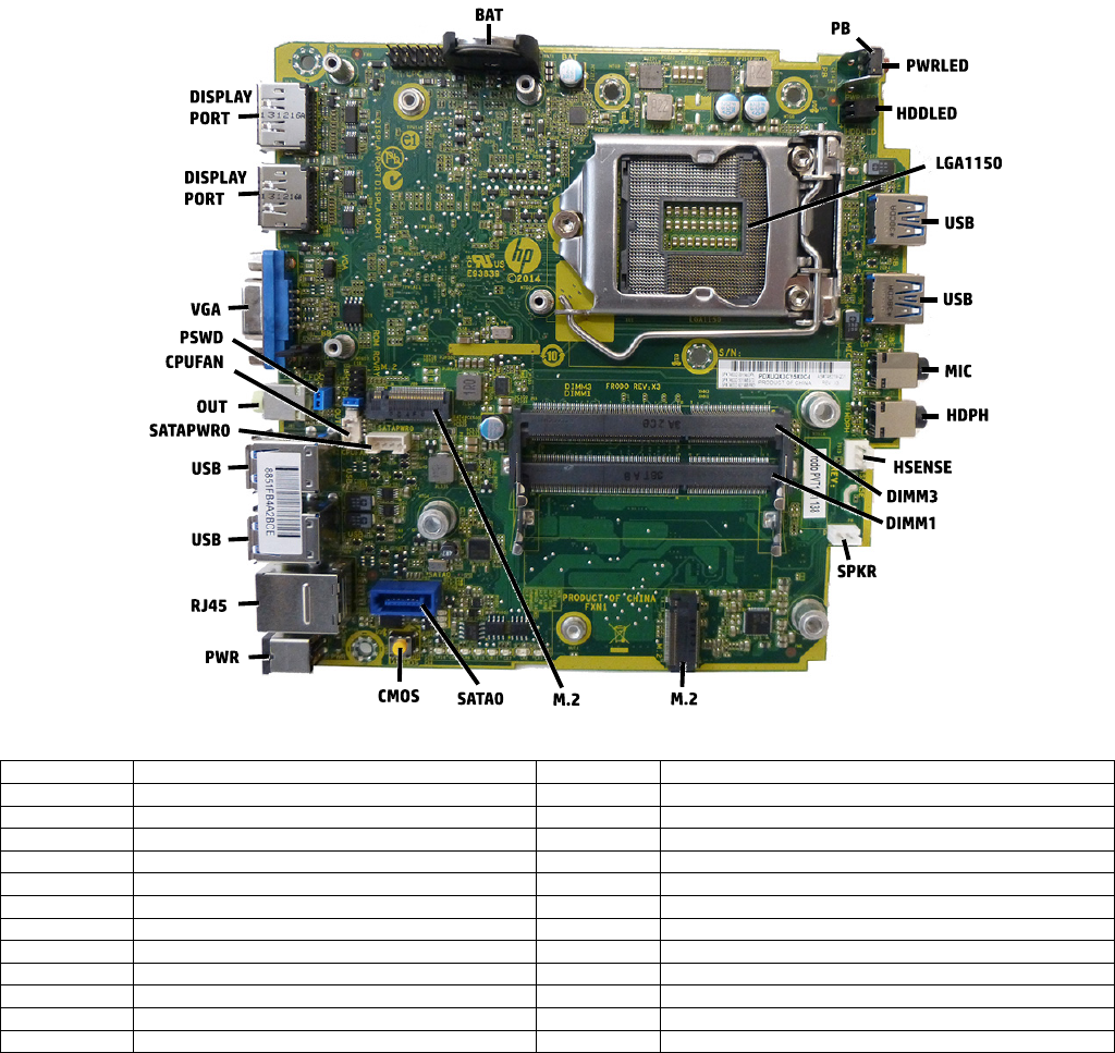
System board
System board connectors and jumpers (component location may vary)
BAT RTC battery socket M.2 SSD connector
PB Power button SATA0 1st hard drive data connector
PWRLED Power light CMOS CMOS button
HDDLED Hard drive activity LED PWR Main power connector
LGA1150 Processor socket RJ45 Network jack
USB External USB 3.0 connectors USB External USB 3.0 connectors (4)
MIC External microphone connector
SATA PWR0
Hard drive power connector
HDPH External headphone connector OUT External audio out connector
HSENSE Hood sensor connector CPUFAN Fan connector
DIMM3 Memory socket - Channel B PSWD Password header
DIMM1 Memory socket - Channel A VGA Display connector
SPKR Speaker connector
DISPLAYPORT
DisplayPort connectors
M.2 WLAN module connector
