Hp Integrity Server Rx4640 Users Manual A6961 96013
rx4640 to the manual 8424e43b-e6c0-4df6-98e3-c82e0164872b
2015-02-09
: Hp Hp-Hp-Integrity-Server-Rx4640-Users-Manual-546546 hp-hp-integrity-server-rx4640-users-manual-546546 hp pdf
Open the PDF directly: View PDF ![]() .
.
Page Count: 197 [warning: Documents this large are best viewed by clicking the View PDF Link!]
- HP Integrity rx4640 Server User Service Guide
- Table of Contents
- List of Tables
- List of Figures
- About This Document
- 1 Introduction
- 2 Controls, Ports, and LEDs
- 3 Powering Off and Powering On the Server
- 4 Removing and Replacing Components
- Safety Information
- Service Tools Required
- Accessing a Rack Mounted Server
- Accessing a Pedestal Mounted Server
- Removing and Replacing the Front Bezel
- Removing and Replacing the Front and Top Covers
- Removing and Replacing the Memory Extender Board
- Removing and Replacing Server Memory DIMMs
- Removing and Replacing the Processor Extender Board
- Removing and Replacing a Processor
- Removing and Replacing Hot-Swap Chassis Fans
- Removing and Replacing the I/O Baseboard
- Removing and Replacing Hot-Plug PCI-X Cards
- Removing and Replacing OLX Dividers
- Removing and Replacing Core I/O Cards
- Removing and Replacing the Server Battery
- Removing and Replacing Hard Disk Drives
- Removing and Replacing the SCSI Backplane Board
- Removing and Replacing the Midplane Riser Board
- Removing and Replacing the Power Supplies
- Removing and Replacing the Power Distribution Board
- Removing and Replacing the DVD Drive
- Removing and Replacing the DVD I/O Board
- Removing and Replacing the Display Board
- Removing and Replacing the QuickFind Diagnostic Board
- 5 Troubleshooting
- A Parts Information
- B Booting the Operating System
- C Utilities
- Index

User Service Guide
HP Integrity rx4640 Server
Manufacturing Part Number: A6961-96013-ed2
Second Edition
November 2008
© Copyright 2006-2008 Hewlett-Packard Development Company, L.P.

2
Legal Notices
Copyright Notices. © Copyright 2006-2008 Hewlett-Packard Development Company, L.P.
The information contained herein is subject to change without notice. The only warranties for HP products
and services are set forth in the express warranty statements accompanying such products and services.
Nothing herein should be construed as constituting an additional warranty. HP shall not be liable for
technical or editorial errors or omissions contained herein.
Intel, Pentium, Intel Inside, Itanium, and the Intel Inside logo are trademarks or registered trademarks of
Intel Corporation or its subsidiaries in the United States and other countries.
Linux is a U.S. registered trademark of Linus Torvalds.
Microsoft and Windows are U.S. registered trademarks of Microsoft Corporation.
Acrobat is a trademark of Adobe Systems Incorporated.
Java is a US trademark of Sun Microsystems, Inc.
UNIX is a registered trademark of The Open Group.

Contents
3
About This Document
Intended Audience . . . . . . . . . . . . . . . . . . . . . . . . . . . . . . . . . . . . . . . . . . . . . . . . . . . . . . . . . . . . . . . . . . . 15
New and Changed Information in This Edition . . . . . . . . . . . . . . . . . . . . . . . . . . . . . . . . . . . . . . . . . . . . 15
Publishing History . . . . . . . . . . . . . . . . . . . . . . . . . . . . . . . . . . . . . . . . . . . . . . . . . . . . . . . . . . . . . . . . . . . 15
Document Organization. . . . . . . . . . . . . . . . . . . . . . . . . . . . . . . . . . . . . . . . . . . . . . . . . . . . . . . . . . . . . . . 16
Typographic Conventions . . . . . . . . . . . . . . . . . . . . . . . . . . . . . . . . . . . . . . . . . . . . . . . . . . . . . . . . . . . . . 16
HP-UX Release Name and Release Identifier . . . . . . . . . . . . . . . . . . . . . . . . . . . . . . . . . . . . . . . . . . . . . 17
Related Documents . . . . . . . . . . . . . . . . . . . . . . . . . . . . . . . . . . . . . . . . . . . . . . . . . . . . . . . . . . . . . . . . . . 17
HP Encourages Your Comments . . . . . . . . . . . . . . . . . . . . . . . . . . . . . . . . . . . . . . . . . . . . . . . . . . . . . . . . 18
1. Introduction
Server Overview. . . . . . . . . . . . . . . . . . . . . . . . . . . . . . . . . . . . . . . . . . . . . . . . . . . . . . . . . . . . . . . . . . . . . 20
Server Dimensions and Weight . . . . . . . . . . . . . . . . . . . . . . . . . . . . . . . . . . . . . . . . . . . . . . . . . . . . . . . . . 21
Server Components . . . . . . . . . . . . . . . . . . . . . . . . . . . . . . . . . . . . . . . . . . . . . . . . . . . . . . . . . . . . . . . . . . 22
Processors . . . . . . . . . . . . . . . . . . . . . . . . . . . . . . . . . . . . . . . . . . . . . . . . . . . . . . . . . . . . . . . . . . . . . . . . 22
Memory . . . . . . . . . . . . . . . . . . . . . . . . . . . . . . . . . . . . . . . . . . . . . . . . . . . . . . . . . . . . . . . . . . . . . . . . . . 22
PCI Riser . . . . . . . . . . . . . . . . . . . . . . . . . . . . . . . . . . . . . . . . . . . . . . . . . . . . . . . . . . . . . . . . . . . . . . . . . 22
Internal Core I/O. . . . . . . . . . . . . . . . . . . . . . . . . . . . . . . . . . . . . . . . . . . . . . . . . . . . . . . . . . . . . . . . . . . 22
External Core I/O . . . . . . . . . . . . . . . . . . . . . . . . . . . . . . . . . . . . . . . . . . . . . . . . . . . . . . . . . . . . . . . . . . 22
Power Supply Unit . . . . . . . . . . . . . . . . . . . . . . . . . . . . . . . . . . . . . . . . . . . . . . . . . . . . . . . . . . . . . . . . . 23
Motherboard Manageability. . . . . . . . . . . . . . . . . . . . . . . . . . . . . . . . . . . . . . . . . . . . . . . . . . . . . . . . . . 23
Enhanced Server Manageability Using Management Processor. . . . . . . . . . . . . . . . . . . . . . . . . . . . . 23
Hard Disk Drives . . . . . . . . . . . . . . . . . . . . . . . . . . . . . . . . . . . . . . . . . . . . . . . . . . . . . . . . . . . . . . . . . . 23
Supported Operating Systems. . . . . . . . . . . . . . . . . . . . . . . . . . . . . . . . . . . . . . . . . . . . . . . . . . . . . . . . . . 24
2. Controls, Ports, and LEDs
Front Panel Controls, Ports, and LEDs . . . . . . . . . . . . . . . . . . . . . . . . . . . . . . . . . . . . . . . . . . . . . . . . . . 26
Hard Disk Drive LED Indicators . . . . . . . . . . . . . . . . . . . . . . . . . . . . . . . . . . . . . . . . . . . . . . . . . . . . . . 27
DVD/DVD-R/DVD-RW Drives . . . . . . . . . . . . . . . . . . . . . . . . . . . . . . . . . . . . . . . . . . . . . . . . . . . . . . . . 28
Rear Panel Controls, Ports, and LEDs . . . . . . . . . . . . . . . . . . . . . . . . . . . . . . . . . . . . . . . . . . . . . . . . . . . 28
Power Supply Status LEDs . . . . . . . . . . . . . . . . . . . . . . . . . . . . . . . . . . . . . . . . . . . . . . . . . . . . . . . . . . 29
Management Processor LAN LEDs . . . . . . . . . . . . . . . . . . . . . . . . . . . . . . . . . . . . . . . . . . . . . . . . . . . . 29
Locator LED and Button . . . . . . . . . . . . . . . . . . . . . . . . . . . . . . . . . . . . . . . . . . . . . . . . . . . . . . . . . . . . 30
Gigabit Ethernet Card LAN Ports (Core I/O) . . . . . . . . . . . . . . . . . . . . . . . . . . . . . . . . . . . . . . . . . . . . 30
Internal Controls, Ports, and LEDs . . . . . . . . . . . . . . . . . . . . . . . . . . . . . . . . . . . . . . . . . . . . . . . . . . . . . 31
QuickFind Diagnostic Panel. . . . . . . . . . . . . . . . . . . . . . . . . . . . . . . . . . . . . . . . . . . . . . . . . . . . . . . . . . 31
I/O Baseboard LED Indicators. . . . . . . . . . . . . . . . . . . . . . . . . . . . . . . . . . . . . . . . . . . . . . . . . . . . . . . . 32
3. Powering Off and Powering On the Server
Power States. . . . . . . . . . . . . . . . . . . . . . . . . . . . . . . . . . . . . . . . . . . . . . . . . . . . . . . . . . . . . . . . . . . . . . . . 34
Powering Off the Server. . . . . . . . . . . . . . . . . . . . . . . . . . . . . . . . . . . . . . . . . . . . . . . . . . . . . . . . . . . . . . . 34
Powering Off the Server Using the iLO MP . . . . . . . . . . . . . . . . . . . . . . . . . . . . . . . . . . . . . . . . . . . . . 34
Powering Off the Server Manually . . . . . . . . . . . . . . . . . . . . . . . . . . . . . . . . . . . . . . . . . . . . . . . . . . . . 35
Powering On the Server. . . . . . . . . . . . . . . . . . . . . . . . . . . . . . . . . . . . . . . . . . . . . . . . . . . . . . . . . . . . . . . 35
Powering On the Server Using the iLO MP . . . . . . . . . . . . . . . . . . . . . . . . . . . . . . . . . . . . . . . . . . . . . 35
Powering On the Server Manually . . . . . . . . . . . . . . . . . . . . . . . . . . . . . . . . . . . . . . . . . . . . . . . . . . . . 36

Contents
4
4. Removing and Replacing Components
Safety Information . . . . . . . . . . . . . . . . . . . . . . . . . . . . . . . . . . . . . . . . . . . . . . . . . . . . . . . . . . . . . . . . . . . 38
Service Tools Required. . . . . . . . . . . . . . . . . . . . . . . . . . . . . . . . . . . . . . . . . . . . . . . . . . . . . . . . . . . . . . . . 38
Accessing a Rack Mounted Server . . . . . . . . . . . . . . . . . . . . . . . . . . . . . . . . . . . . . . . . . . . . . . . . . . . . . . 38
Extending the Server from the Rack . . . . . . . . . . . . . . . . . . . . . . . . . . . . . . . . . . . . . . . . . . . . . . . . . . . 39
Inserting the Server into the Rack . . . . . . . . . . . . . . . . . . . . . . . . . . . . . . . . . . . . . . . . . . . . . . . . . . . . 39
Accessing a Pedestal Mounted Server . . . . . . . . . . . . . . . . . . . . . . . . . . . . . . . . . . . . . . . . . . . . . . . . . . . 40
Removing and Replacing the Front Bezel. . . . . . . . . . . . . . . . . . . . . . . . . . . . . . . . . . . . . . . . . . . . . . . . . 41
Removing the Front Bezel . . . . . . . . . . . . . . . . . . . . . . . . . . . . . . . . . . . . . . . . . . . . . . . . . . . . . . . . . . . 41
Replacing the Front Bezel . . . . . . . . . . . . . . . . . . . . . . . . . . . . . . . . . . . . . . . . . . . . . . . . . . . . . . . . . . . 41
Removing and Replacing the Front and Top Covers . . . . . . . . . . . . . . . . . . . . . . . . . . . . . . . . . . . . . . . . 42
Removing the Front Cover . . . . . . . . . . . . . . . . . . . . . . . . . . . . . . . . . . . . . . . . . . . . . . . . . . . . . . . . . . . 42
Replacing the Front Cover . . . . . . . . . . . . . . . . . . . . . . . . . . . . . . . . . . . . . . . . . . . . . . . . . . . . . . . . . . . 43
Removing the Top Cover. . . . . . . . . . . . . . . . . . . . . . . . . . . . . . . . . . . . . . . . . . . . . . . . . . . . . . . . . . . . . 43
Replacing the Top Cover. . . . . . . . . . . . . . . . . . . . . . . . . . . . . . . . . . . . . . . . . . . . . . . . . . . . . . . . . . . . . 44
Removing and Replacing the Memory Extender Board. . . . . . . . . . . . . . . . . . . . . . . . . . . . . . . . . . . . . . 44
Removing the Memory Extender Board . . . . . . . . . . . . . . . . . . . . . . . . . . . . . . . . . . . . . . . . . . . . . . . . 44
Replacing the Memory Extender Board . . . . . . . . . . . . . . . . . . . . . . . . . . . . . . . . . . . . . . . . . . . . . . . . 46
Removing and Replacing Server Memory DIMMs. . . . . . . . . . . . . . . . . . . . . . . . . . . . . . . . . . . . . . . . . . 46
Removing Server Memory DIMMs . . . . . . . . . . . . . . . . . . . . . . . . . . . . . . . . . . . . . . . . . . . . . . . . . . . . 46
Installing Memory DIMMs. . . . . . . . . . . . . . . . . . . . . . . . . . . . . . . . . . . . . . . . . . . . . . . . . . . . . . . . . . . 47
16 DIMM Memory Extender Board Layout . . . . . . . . . . . . . . . . . . . . . . . . . . . . . . . . . . . . . . . . . . . . . 49
32 DIMM Memory Extender Board Layout . . . . . . . . . . . . . . . . . . . . . . . . . . . . . . . . . . . . . . . . . . . . . 50
Removing and Replacing the Processor Extender Board. . . . . . . . . . . . . . . . . . . . . . . . . . . . . . . . . . . . . 52
Removing the Processor Extender Board . . . . . . . . . . . . . . . . . . . . . . . . . . . . . . . . . . . . . . . . . . . . . . . 52
Replacing the Processor Extender Board . . . . . . . . . . . . . . . . . . . . . . . . . . . . . . . . . . . . . . . . . . . . . . . 54
Removing and Replacing a Processor . . . . . . . . . . . . . . . . . . . . . . . . . . . . . . . . . . . . . . . . . . . . . . . . . . . . 55
Processor Load Order . . . . . . . . . . . . . . . . . . . . . . . . . . . . . . . . . . . . . . . . . . . . . . . . . . . . . . . . . . . . . . . 55
Removing a Processor. . . . . . . . . . . . . . . . . . . . . . . . . . . . . . . . . . . . . . . . . . . . . . . . . . . . . . . . . . . . . . . 56
Replacing a Processor . . . . . . . . . . . . . . . . . . . . . . . . . . . . . . . . . . . . . . . . . . . . . . . . . . . . . . . . . . . . . . . 58
Removing and Replacing Hot-Swap Chassis Fans. . . . . . . . . . . . . . . . . . . . . . . . . . . . . . . . . . . . . . . . . . 63
Removing a Hot-Swap Chassis Fan Unit . . . . . . . . . . . . . . . . . . . . . . . . . . . . . . . . . . . . . . . . . . . . . . . 63
Replacing a Hot-Swap Chassis Fan Unit. . . . . . . . . . . . . . . . . . . . . . . . . . . . . . . . . . . . . . . . . . . . . . . . 65
Removing and Replacing the I/O Baseboard . . . . . . . . . . . . . . . . . . . . . . . . . . . . . . . . . . . . . . . . . . . . . . 66
Removing the I/O Baseboard . . . . . . . . . . . . . . . . . . . . . . . . . . . . . . . . . . . . . . . . . . . . . . . . . . . . . . . . . 66
Replacing the I/O Baseboard . . . . . . . . . . . . . . . . . . . . . . . . . . . . . . . . . . . . . . . . . . . . . . . . . . . . . . . . . 68
Removing and Replacing Hot-Plug PCI-X Cards . . . . . . . . . . . . . . . . . . . . . . . . . . . . . . . . . . . . . . . . . . . 71
PCI-X Specifications . . . . . . . . . . . . . . . . . . . . . . . . . . . . . . . . . . . . . . . . . . . . . . . . . . . . . . . . . . . . . . . . 71
Operating System Support for Hot-Plug PCI-X Operations. . . . . . . . . . . . . . . . . . . . . . . . . . . . . . . . . 72
PCI-X Hardware and Software Interfaces. . . . . . . . . . . . . . . . . . . . . . . . . . . . . . . . . . . . . . . . . . . . . . . 73
PCI-X Slot Locations and Configurations . . . . . . . . . . . . . . . . . . . . . . . . . . . . . . . . . . . . . . . . . . . . . . . 74
Hot-Plug Operation Procedures . . . . . . . . . . . . . . . . . . . . . . . . . . . . . . . . . . . . . . . . . . . . . . . . . . . . . . . 77
Removing and Replacing OLX Dividers . . . . . . . . . . . . . . . . . . . . . . . . . . . . . . . . . . . . . . . . . . . . . . . . . . 81
Removing an OLX Divider . . . . . . . . . . . . . . . . . . . . . . . . . . . . . . . . . . . . . . . . . . . . . . . . . . . . . . . . . . . 81
Replacing an OLX Divider . . . . . . . . . . . . . . . . . . . . . . . . . . . . . . . . . . . . . . . . . . . . . . . . . . . . . . . . . . . 84
Removing and Replacing Core I/O Cards . . . . . . . . . . . . . . . . . . . . . . . . . . . . . . . . . . . . . . . . . . . . . . . . . 85

Contents
5
PCI Slot Locations and Configurations . . . . . . . . . . . . . . . . . . . . . . . . . . . . . . . . . . . . . . . . . . . . . . . . . 85
Removing and Replacing the SCSI Core I/O Card . . . . . . . . . . . . . . . . . . . . . . . . . . . . . . . . . . . . . . . . 86
Removing and Replacing the LAN Core I/O Card . . . . . . . . . . . . . . . . . . . . . . . . . . . . . . . . . . . . . . . . 88
Removing and Replacing the Server Battery . . . . . . . . . . . . . . . . . . . . . . . . . . . . . . . . . . . . . . . . . . . . . . 89
Removing and Replacing Hard Disk Drives . . . . . . . . . . . . . . . . . . . . . . . . . . . . . . . . . . . . . . . . . . . . . . . 90
Removing a Hard Disk Drive . . . . . . . . . . . . . . . . . . . . . . . . . . . . . . . . . . . . . . . . . . . . . . . . . . . . . . . . . 90
Replacing a Hard Disk Drive . . . . . . . . . . . . . . . . . . . . . . . . . . . . . . . . . . . . . . . . . . . . . . . . . . . . . . . . . 90
Removing and Replacing the SCSI Backplane Board . . . . . . . . . . . . . . . . . . . . . . . . . . . . . . . . . . . . . . . 93
Removing the SCSI Backplane Board . . . . . . . . . . . . . . . . . . . . . . . . . . . . . . . . . . . . . . . . . . . . . . . . . . 93
Replacing the SCSI Backplane Board . . . . . . . . . . . . . . . . . . . . . . . . . . . . . . . . . . . . . . . . . . . . . . . . . . 94
Removing and Replacing the Midplane Riser Board . . . . . . . . . . . . . . . . . . . . . . . . . . . . . . . . . . . . . . . . 95
Removing the Midplane Riser Board. . . . . . . . . . . . . . . . . . . . . . . . . . . . . . . . . . . . . . . . . . . . . . . . . . . 95
Replacing the Midplane Riser Board. . . . . . . . . . . . . . . . . . . . . . . . . . . . . . . . . . . . . . . . . . . . . . . . . . . 97
Removing and Replacing the Power Supplies . . . . . . . . . . . . . . . . . . . . . . . . . . . . . . . . . . . . . . . . . . . . . 98
Power Supply Load Order . . . . . . . . . . . . . . . . . . . . . . . . . . . . . . . . . . . . . . . . . . . . . . . . . . . . . . . . . . . 98
Removing a Hot-Swap Power Supply . . . . . . . . . . . . . . . . . . . . . . . . . . . . . . . . . . . . . . . . . . . . . . . . . . 98
Replacing a Hot-Swap Power Supply. . . . . . . . . . . . . . . . . . . . . . . . . . . . . . . . . . . . . . . . . . . . . . . . . . . 99
Removing and Replacing the Power Distribution Board . . . . . . . . . . . . . . . . . . . . . . . . . . . . . . . . . . . . 100
Removing the Power Distribution Board. . . . . . . . . . . . . . . . . . . . . . . . . . . . . . . . . . . . . . . . . . . . . . . 100
Replacing the Power Distribution Board. . . . . . . . . . . . . . . . . . . . . . . . . . . . . . . . . . . . . . . . . . . . . . . 101
Removing and Replacing the DVD Drive . . . . . . . . . . . . . . . . . . . . . . . . . . . . . . . . . . . . . . . . . . . . . . . . 102
Removing the DVD Drive . . . . . . . . . . . . . . . . . . . . . . . . . . . . . . . . . . . . . . . . . . . . . . . . . . . . . . . . . . . 102
Replacing the DVD Drive . . . . . . . . . . . . . . . . . . . . . . . . . . . . . . . . . . . . . . . . . . . . . . . . . . . . . . . . . . . 103
Removing and Replacing the DVD I/O Board . . . . . . . . . . . . . . . . . . . . . . . . . . . . . . . . . . . . . . . . . . . . 104
Removing the DVD I/O Board . . . . . . . . . . . . . . . . . . . . . . . . . . . . . . . . . . . . . . . . . . . . . . . . . . . . . . . 104
Replacing the DVD I/O Board . . . . . . . . . . . . . . . . . . . . . . . . . . . . . . . . . . . . . . . . . . . . . . . . . . . . . . . 106
Removing and Replacing the Display Board . . . . . . . . . . . . . . . . . . . . . . . . . . . . . . . . . . . . . . . . . . . . . 107
Removing the Display Board . . . . . . . . . . . . . . . . . . . . . . . . . . . . . . . . . . . . . . . . . . . . . . . . . . . . . . . . 107
Replacing the Display Board . . . . . . . . . . . . . . . . . . . . . . . . . . . . . . . . . . . . . . . . . . . . . . . . . . . . . . . . 108
Removing and Replacing the QuickFind Diagnostic Board. . . . . . . . . . . . . . . . . . . . . . . . . . . . . . . . . . 109
Removing the QuickFind Diagnostic Board . . . . . . . . . . . . . . . . . . . . . . . . . . . . . . . . . . . . . . . . . . . . 109
Replacing the QuickFind Diagnostic Board . . . . . . . . . . . . . . . . . . . . . . . . . . . . . . . . . . . . . . . . . . . . 110
5. Troubleshooting
Troubleshooting Tips . . . . . . . . . . . . . . . . . . . . . . . . . . . . . . . . . . . . . . . . . . . . . . . . . . . . . . . . . . . . . . . . 112
Troubleshooting Methodology . . . . . . . . . . . . . . . . . . . . . . . . . . . . . . . . . . . . . . . . . . . . . . . . . . . . . . . 112
Possible Problems. . . . . . . . . . . . . . . . . . . . . . . . . . . . . . . . . . . . . . . . . . . . . . . . . . . . . . . . . . . . . . . . . . . 113
The Server Does Not Power On . . . . . . . . . . . . . . . . . . . . . . . . . . . . . . . . . . . . . . . . . . . . . . . . . . . . . . 113
The Server Does Not Boot . . . . . . . . . . . . . . . . . . . . . . . . . . . . . . . . . . . . . . . . . . . . . . . . . . . . . . . . . . 113
The Server Has Intermittent Failures. . . . . . . . . . . . . . . . . . . . . . . . . . . . . . . . . . . . . . . . . . . . . . . . . 114
The Server LED or Diagnostic LEDs Are Not On and No Error Messages Appear . . . . . . . . . . . . . 115
Power Shuts Off and Does Not Come Back On . . . . . . . . . . . . . . . . . . . . . . . . . . . . . . . . . . . . . . . . . . 115
Troubleshooting Using LED Indicators . . . . . . . . . . . . . . . . . . . . . . . . . . . . . . . . . . . . . . . . . . . . . . . . . 116
Front Control Panel LED Indicators . . . . . . . . . . . . . . . . . . . . . . . . . . . . . . . . . . . . . . . . . . . . . . . . . . 117
Hard Disk Drive LED Indicators . . . . . . . . . . . . . . . . . . . . . . . . . . . . . . . . . . . . . . . . . . . . . . . . . . . . . 118
DVD/DVD-R/DVD-RW Drive LED Indicators. . . . . . . . . . . . . . . . . . . . . . . . . . . . . . . . . . . . . . . . . . . 118

Contents
6
QuickFind Diagnostic Panel LED Indicators . . . . . . . . . . . . . . . . . . . . . . . . . . . . . . . . . . . . . . . . . . . 119
I/O Baseboard LED Indicators. . . . . . . . . . . . . . . . . . . . . . . . . . . . . . . . . . . . . . . . . . . . . . . . . . . . . . . 121
Power Supply Status LED Indicators . . . . . . . . . . . . . . . . . . . . . . . . . . . . . . . . . . . . . . . . . . . . . . . . . 123
iLO MP LAN Port Link/Activity LED Display . . . . . . . . . . . . . . . . . . . . . . . . . . . . . . . . . . . . . . . . . . 123
Locator LED and Button . . . . . . . . . . . . . . . . . . . . . . . . . . . . . . . . . . . . . . . . . . . . . . . . . . . . . . . . . . . 125
PCI-X LEDs and Hardware Errors . . . . . . . . . . . . . . . . . . . . . . . . . . . . . . . . . . . . . . . . . . . . . . . . . . . 126
Diagnostics . . . . . . . . . . . . . . . . . . . . . . . . . . . . . . . . . . . . . . . . . . . . . . . . . . . . . . . . . . . . . . . . . . . . . . . . 128
Online Diagnostics/Exercisers . . . . . . . . . . . . . . . . . . . . . . . . . . . . . . . . . . . . . . . . . . . . . . . . . . . . . . . 128
Offline Support Tool Availability . . . . . . . . . . . . . . . . . . . . . . . . . . . . . . . . . . . . . . . . . . . . . . . . . . . . . 129
Offline Support Tools List . . . . . . . . . . . . . . . . . . . . . . . . . . . . . . . . . . . . . . . . . . . . . . . . . . . . . . . . . . 129
General Diagnostic Tools . . . . . . . . . . . . . . . . . . . . . . . . . . . . . . . . . . . . . . . . . . . . . . . . . . . . . . . . . . . 130
Fault Management Overview. . . . . . . . . . . . . . . . . . . . . . . . . . . . . . . . . . . . . . . . . . . . . . . . . . . . . . . . 130
HP-UX Fault Management. . . . . . . . . . . . . . . . . . . . . . . . . . . . . . . . . . . . . . . . . . . . . . . . . . . . . . . . . . 130
Recommended Cleaning Procedures . . . . . . . . . . . . . . . . . . . . . . . . . . . . . . . . . . . . . . . . . . . . . . . . . . . . 131
Where to Get Help . . . . . . . . . . . . . . . . . . . . . . . . . . . . . . . . . . . . . . . . . . . . . . . . . . . . . . . . . . . . . . . . . . 132
Information to Collect Before you Contact Support . . . . . . . . . . . . . . . . . . . . . . . . . . . . . . . . . . . . . . 132
Online Support . . . . . . . . . . . . . . . . . . . . . . . . . . . . . . . . . . . . . . . . . . . . . . . . . . . . . . . . . . . . . . . . . . . 132
Phone Support. . . . . . . . . . . . . . . . . . . . . . . . . . . . . . . . . . . . . . . . . . . . . . . . . . . . . . . . . . . . . . . . . . . . 133
A. Parts Information
Field Replaceable Parts List . . . . . . . . . . . . . . . . . . . . . . . . . . . . . . . . . . . . . . . . . . . . . . . . . . . . . . . . . . 136
B. Booting the Operating System
Operating Systems Supported on HP Integrity Servers . . . . . . . . . . . . . . . . . . . . . . . . . . . . . . . . . . . . 142
Configuring System Boot Options. . . . . . . . . . . . . . . . . . . . . . . . . . . . . . . . . . . . . . . . . . . . . . . . . . . . . . 142
Booting and Shutting Down HP-UX . . . . . . . . . . . . . . . . . . . . . . . . . . . . . . . . . . . . . . . . . . . . . . . . . . . . 143
Adding HP-UX to the Boot Options List . . . . . . . . . . . . . . . . . . . . . . . . . . . . . . . . . . . . . . . . . . . . . . . 144
Standard HP-UX Booting. . . . . . . . . . . . . . . . . . . . . . . . . . . . . . . . . . . . . . . . . . . . . . . . . . . . . . . . . . . 145
Single-User Mode HP-UX Booting. . . . . . . . . . . . . . . . . . . . . . . . . . . . . . . . . . . . . . . . . . . . . . . . . . . . 146
LVM Maintenance Mode HP-UX Booting . . . . . . . . . . . . . . . . . . . . . . . . . . . . . . . . . . . . . . . . . . . . . . 148
Shutting Down HP-UX . . . . . . . . . . . . . . . . . . . . . . . . . . . . . . . . . . . . . . . . . . . . . . . . . . . . . . . . . . . . . 148
Booting and Shutting Down HP OpenVMS . . . . . . . . . . . . . . . . . . . . . . . . . . . . . . . . . . . . . . . . . . . . . . 149
Adding HP OpenVMS to the Boot Options List . . . . . . . . . . . . . . . . . . . . . . . . . . . . . . . . . . . . . . . . . 149
Booting HP OpenVMS . . . . . . . . . . . . . . . . . . . . . . . . . . . . . . . . . . . . . . . . . . . . . . . . . . . . . . . . . . . . . 150
Shutting Down HP OpenVMS . . . . . . . . . . . . . . . . . . . . . . . . . . . . . . . . . . . . . . . . . . . . . . . . . . . . . . . 152
Booting and Shutting Down Microsoft Windows . . . . . . . . . . . . . . . . . . . . . . . . . . . . . . . . . . . . . . . . . . 153
Adding Microsoft Windows to the Boot Options List . . . . . . . . . . . . . . . . . . . . . . . . . . . . . . . . . . . . . 153
Booting the Microsoft Windows Operating System . . . . . . . . . . . . . . . . . . . . . . . . . . . . . . . . . . . . . . 154
Shutting Down Microsoft Windows . . . . . . . . . . . . . . . . . . . . . . . . . . . . . . . . . . . . . . . . . . . . . . . . . . . 155
Booting and Shutting Down Linux . . . . . . . . . . . . . . . . . . . . . . . . . . . . . . . . . . . . . . . . . . . . . . . . . . . . . 157
Adding Linux to the Boot Options List . . . . . . . . . . . . . . . . . . . . . . . . . . . . . . . . . . . . . . . . . . . . . . . . 157
Booting the Red Hat Enterprise Linux Operating System . . . . . . . . . . . . . . . . . . . . . . . . . . . . . . . . 158
Booting the SuSE Linux Enterprise Server Operating System. . . . . . . . . . . . . . . . . . . . . . . . . . . . . 159
Shutting Down Linux . . . . . . . . . . . . . . . . . . . . . . . . . . . . . . . . . . . . . . . . . . . . . . . . . . . . . . . . . . . . . . 160
C. Utilities

Contents
7
Extensible Firmware Interface Boot Manager. . . . . . . . . . . . . . . . . . . . . . . . . . . . . . . . . . . . . . . . . . . . 162
EFI Commands . . . . . . . . . . . . . . . . . . . . . . . . . . . . . . . . . . . . . . . . . . . . . . . . . . . . . . . . . . . . . . . . . . . 164
EFI/POSSE Commands . . . . . . . . . . . . . . . . . . . . . . . . . . . . . . . . . . . . . . . . . . . . . . . . . . . . . . . . . . . . . . 166
help . . . . . . . . . . . . . . . . . . . . . . . . . . . . . . . . . . . . . . . . . . . . . . . . . . . . . . . . . . . . . . . . . . . . . . . . . . . . 166
baud . . . . . . . . . . . . . . . . . . . . . . . . . . . . . . . . . . . . . . . . . . . . . . . . . . . . . . . . . . . . . . . . . . . . . . . . . . . . 168
boottest . . . . . . . . . . . . . . . . . . . . . . . . . . . . . . . . . . . . . . . . . . . . . . . . . . . . . . . . . . . . . . . . . . . . . . . . . 168
cpuconfig . . . . . . . . . . . . . . . . . . . . . . . . . . . . . . . . . . . . . . . . . . . . . . . . . . . . . . . . . . . . . . . . . . . . . . . . 169
ioconfig. . . . . . . . . . . . . . . . . . . . . . . . . . . . . . . . . . . . . . . . . . . . . . . . . . . . . . . . . . . . . . . . . . . . . . . . . . 170
default . . . . . . . . . . . . . . . . . . . . . . . . . . . . . . . . . . . . . . . . . . . . . . . . . . . . . . . . . . . . . . . . . . . . . . . . . . 171
errdump. . . . . . . . . . . . . . . . . . . . . . . . . . . . . . . . . . . . . . . . . . . . . . . . . . . . . . . . . . . . . . . . . . . . . . . . . 171
info . . . . . . . . . . . . . . . . . . . . . . . . . . . . . . . . . . . . . . . . . . . . . . . . . . . . . . . . . . . . . . . . . . . . . . . . . . . . . 172
lanaddress . . . . . . . . . . . . . . . . . . . . . . . . . . . . . . . . . . . . . . . . . . . . . . . . . . . . . . . . . . . . . . . . . . . . . . . 177
monarch. . . . . . . . . . . . . . . . . . . . . . . . . . . . . . . . . . . . . . . . . . . . . . . . . . . . . . . . . . . . . . . . . . . . . . . . . 178
pdt . . . . . . . . . . . . . . . . . . . . . . . . . . . . . . . . . . . . . . . . . . . . . . . . . . . . . . . . . . . . . . . . . . . . . . . . . . . . . 178
sysmode . . . . . . . . . . . . . . . . . . . . . . . . . . . . . . . . . . . . . . . . . . . . . . . . . . . . . . . . . . . . . . . . . . . . . . . . . 179
Specifying SCSI Parameters . . . . . . . . . . . . . . . . . . . . . . . . . . . . . . . . . . . . . . . . . . . . . . . . . . . . . . . . . . 180
Using the SCSI Setup Utility. . . . . . . . . . . . . . . . . . . . . . . . . . . . . . . . . . . . . . . . . . . . . . . . . . . . . . . . 180
Using the Boot Configuration Menu . . . . . . . . . . . . . . . . . . . . . . . . . . . . . . . . . . . . . . . . . . . . . . . . . . . . 186
Boot From File . . . . . . . . . . . . . . . . . . . . . . . . . . . . . . . . . . . . . . . . . . . . . . . . . . . . . . . . . . . . . . . . . . . 186
Add Boot Entry . . . . . . . . . . . . . . . . . . . . . . . . . . . . . . . . . . . . . . . . . . . . . . . . . . . . . . . . . . . . . . . . . . . 187
Edit Boot Entry. . . . . . . . . . . . . . . . . . . . . . . . . . . . . . . . . . . . . . . . . . . . . . . . . . . . . . . . . . . . . . . . . . . 187
Remove Boot Entry . . . . . . . . . . . . . . . . . . . . . . . . . . . . . . . . . . . . . . . . . . . . . . . . . . . . . . . . . . . . . . . . 188
BootNext Configuration . . . . . . . . . . . . . . . . . . . . . . . . . . . . . . . . . . . . . . . . . . . . . . . . . . . . . . . . . . . . 188
AutoBoot Configuration . . . . . . . . . . . . . . . . . . . . . . . . . . . . . . . . . . . . . . . . . . . . . . . . . . . . . . . . . . . . 189
Driver Configuration . . . . . . . . . . . . . . . . . . . . . . . . . . . . . . . . . . . . . . . . . . . . . . . . . . . . . . . . . . . . . . 189
Driver Configuration . . . . . . . . . . . . . . . . . . . . . . . . . . . . . . . . . . . . . . . . . . . . . . . . . . . . . . . . . . . . . . 190
Console Configuration . . . . . . . . . . . . . . . . . . . . . . . . . . . . . . . . . . . . . . . . . . . . . . . . . . . . . . . . . . . . . 191
System Reset. . . . . . . . . . . . . . . . . . . . . . . . . . . . . . . . . . . . . . . . . . . . . . . . . . . . . . . . . . . . . . . . . . . . . 192
Using the System Configuration Menu . . . . . . . . . . . . . . . . . . . . . . . . . . . . . . . . . . . . . . . . . . . . . . . . 193
Using the Security Configuration Menu . . . . . . . . . . . . . . . . . . . . . . . . . . . . . . . . . . . . . . . . . . . . . . . 194
Index . . . . . . . . . . . . . . . . . . . . . . . . . . . . . . . . . . . . . . . . . . . . . . . . . . . . . . . . . . . . . . . . . . . . . . 195

Contents
8

Tables
9
Table 1. Publishing History Details . . . . . . . . . . . . . . . . . . . . . . . . . . . . . . . . . . . . . . . . . . . . . . . . . . 15
Table 2. HP-UX 11i Releases . . . . . . . . . . . . . . . . . . . . . . . . . . . . . . . . . . . . . . . . . . . . . . . . . . . . . . . . 17
Table 1-1. Server Dimensions . . . . . . . . . . . . . . . . . . . . . . . . . . . . . . . . . . . . . . . . . . . . . . . . . . . . . . . 21
Table 3-1. Power States . . . . . . . . . . . . . . . . . . . . . . . . . . . . . . . . . . . . . . . . . . . . . . . . . . . . . . . . . . . . 34
Table 4-1. Quads on the 16 DIMM Memory Extender Board . . . . . . . . . . . . . . . . . . . . . . . . . . . . . . 49
Table 4-2. DIMM Filler Requirements for 16 DIMM Extender Board . . . . . . . . . . . . . . . . . . . . . . . 50
Table 4-3. Quads on the Optional 32 DIMM Memory Extender Board. . . . . . . . . . . . . . . . . . . . . . . 51
Table 4-4. DIMM Filler Requirements for 32 DIMM Extender Board . . . . . . . . . . . . . . . . . . . . . . . 51
Table 4-5. Processor Load Order . . . . . . . . . . . . . . . . . . . . . . . . . . . . . . . . . . . . . . . . . . . . . . . . . . . . . 55
Table 4-6. Hot-Plug Operation and OS Compatibility . . . . . . . . . . . . . . . . . . . . . . . . . . . . . . . . . . . . 72
Table 4-7. Hot-Plug Hardware and Software Interfaces and OS Availability . . . . . . . . . . . . . . . . . 73
Table 4-8. PCI-X Card vs. Slot Frequency/Bus Mode Compatibility for Shared Slots . . . . . . . . . . . 75
Table 5-1. Front Control Panel LED Definitions . . . . . . . . . . . . . . . . . . . . . . . . . . . . . . . . . . . . . . . 117
Table 5-2. Hot-Swap Disk Drive LED Definitions . . . . . . . . . . . . . . . . . . . . . . . . . . . . . . . . . . . . . . 118
Table 5-3. DVD Drive LED Definitions. . . . . . . . . . . . . . . . . . . . . . . . . . . . . . . . . . . . . . . . . . . . . . . 118
Table 5-4. QuickFind Diagnostic Panel LED Definitions. . . . . . . . . . . . . . . . . . . . . . . . . . . . . . . . . 119
Table 5-5. I/O Baseboard LEDs, Buttons and Sensors. . . . . . . . . . . . . . . . . . . . . . . . . . . . . . . . . . . 122
Table 5-6. Power Supply Status LED . . . . . . . . . . . . . . . . . . . . . . . . . . . . . . . . . . . . . . . . . . . . . . . . 123
Table 5-7. iLO MP LED Status Descriptions . . . . . . . . . . . . . . . . . . . . . . . . . . . . . . . . . . . . . . . . . . 124
Table 5-8. iLO MP LED Status Descriptions . . . . . . . . . . . . . . . . . . . . . . . . . . . . . . . . . . . . . . . . . . 124
Table 5-9. PCI-X LED Descriptions. . . . . . . . . . . . . . . . . . . . . . . . . . . . . . . . . . . . . . . . . . . . . . . . . . 126
Table 5-10. Online Support Tools List. . . . . . . . . . . . . . . . . . . . . . . . . . . . . . . . . . . . . . . . . . . . . . . . 129
Table 5-11. Offline Support Tools List . . . . . . . . . . . . . . . . . . . . . . . . . . . . . . . . . . . . . . . . . . . . . . . 129
Table 5-12. General Diagnostic Tools List . . . . . . . . . . . . . . . . . . . . . . . . . . . . . . . . . . . . . . . . . . . . 130
Table 5-13. Cleaning . . . . . . . . . . . . . . . . . . . . . . . . . . . . . . . . . . . . . . . . . . . . . . . . . . . . . . . . . . . . . 131
Table A-1. Parts List . . . . . . . . . . . . . . . . . . . . . . . . . . . . . . . . . . . . . . . . . . . . . . . . . . . . . . . . . . . . . 136
Table C-1. EFI Commands. . . . . . . . . . . . . . . . . . . . . . . . . . . . . . . . . . . . . . . . . . . . . . . . . . . . . . . . . 164
Table C-2. Communications Parameters . . . . . . . . . . . . . . . . . . . . . . . . . . . . . . . . . . . . . . . . . . . . . 168
Table C-3. Console Output Devices . . . . . . . . . . . . . . . . . . . . . . . . . . . . . . . . . . . . . . . . . . . . . . . . . . 190
Table C-4. Console Output Devices . . . . . . . . . . . . . . . . . . . . . . . . . . . . . . . . . . . . . . . . . . . . . . . . . . 191
Table C-5. Console Output Devices . . . . . . . . . . . . . . . . . . . . . . . . . . . . . . . . . . . . . . . . . . . . . . . . . . 192
Table C-6. Console Output Devices . . . . . . . . . . . . . . . . . . . . . . . . . . . . . . . . . . . . . . . . . . . . . . . . . . 193

Tables
10

Figures
11
Figure 1-1. HP Integrity rx4640 Server with Front Bezel. . . . . . . . . . . . . . . . . . . . . . . . . . . . . . . . . 20
Figure 1-2. HP Integrity rx4640 Server (front view with bezel removed) . . . . . . . . . . . . . . . . . . . . 21
Figure 1-3. HP Integrity rx4640 Server (rear view). . . . . . . . . . . . . . . . . . . . . . . . . . . . . . . . . . . . . . 21
Figure 2-1. Front View with Bezel . . . . . . . . . . . . . . . . . . . . . . . . . . . . . . . . . . . . . . . . . . . . . . . . . . . 26
Figure 2-2. Accessing the Control Panel . . . . . . . . . . . . . . . . . . . . . . . . . . . . . . . . . . . . . . . . . . . . . . . 26
Figure 2-3. Control Panel LEDs . . . . . . . . . . . . . . . . . . . . . . . . . . . . . . . . . . . . . . . . . . . . . . . . . . . . . 27
Figure 2-4. Hard Disk Drive LED Indicators . . . . . . . . . . . . . . . . . . . . . . . . . . . . . . . . . . . . . . . . . . . 27
Figure 2-5. DVD–ROM Drive . . . . . . . . . . . . . . . . . . . . . . . . . . . . . . . . . . . . . . . . . . . . . . . . . . . . . . . 28
Figure 2-6. Rack Mount and Pedestal Rear View. . . . . . . . . . . . . . . . . . . . . . . . . . . . . . . . . . . . . . . . 28
Figure 2-7. Power Supply Status LEDs . . . . . . . . . . . . . . . . . . . . . . . . . . . . . . . . . . . . . . . . . . . . . . . 29
Figure 2-8. MP LAN LEDs . . . . . . . . . . . . . . . . . . . . . . . . . . . . . . . . . . . . . . . . . . . . . . . . . . . . . . . . . 29
Figure 2-9. Core I/O LAN Port LEDs . . . . . . . . . . . . . . . . . . . . . . . . . . . . . . . . . . . . . . . . . . . . . . . . . 30
Figure 2-10. QuickFind Diagnostic Panel . . . . . . . . . . . . . . . . . . . . . . . . . . . . . . . . . . . . . . . . . . . . . . 31
Figure 2-11. I/O Baseboard LEDs, Buttons, and Sensors . . . . . . . . . . . . . . . . . . . . . . . . . . . . . . . . . 32
Figure 4-1. Accessing 25MM Torx Screws . . . . . . . . . . . . . . . . . . . . . . . . . . . . . . . . . . . . . . . . . . . . . 39
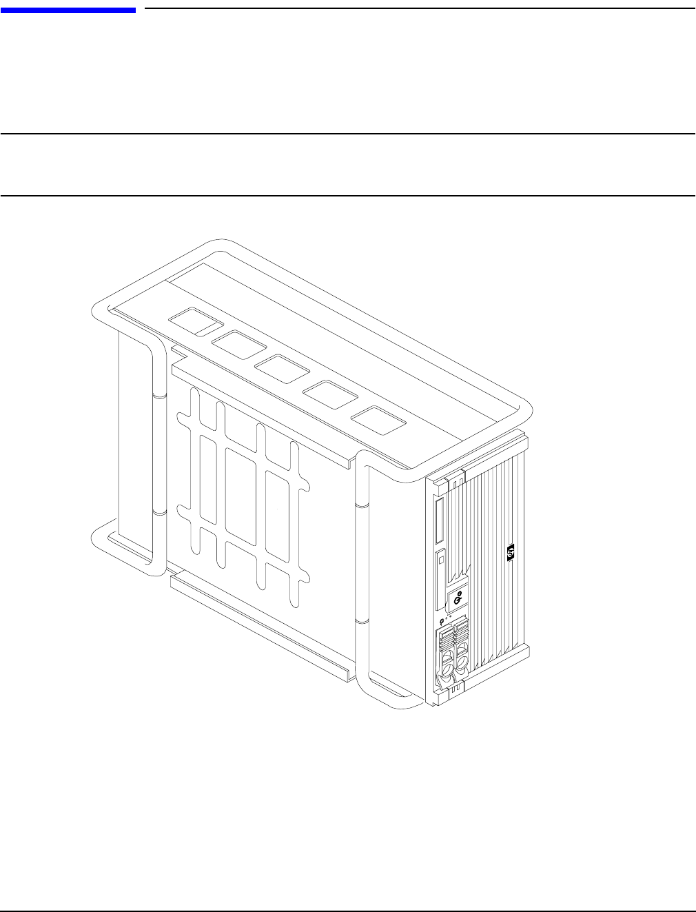
Figure 4-2. Pedestal Mounted HP Integrity rx4640 Server. . . . . . . . . . . . . . . . . . . . . . . . . . . . . . . . 40
Figure 4-3. Removing and Replacing the Front Bezel . . . . . . . . . . . . . . . . . . . . . . . . . . . . . . . . . . . . 41
Figure 4-4. Removing and Replacing the Front Cover. . . . . . . . . . . . . . . . . . . . . . . . . . . . . . . . . . . . 42
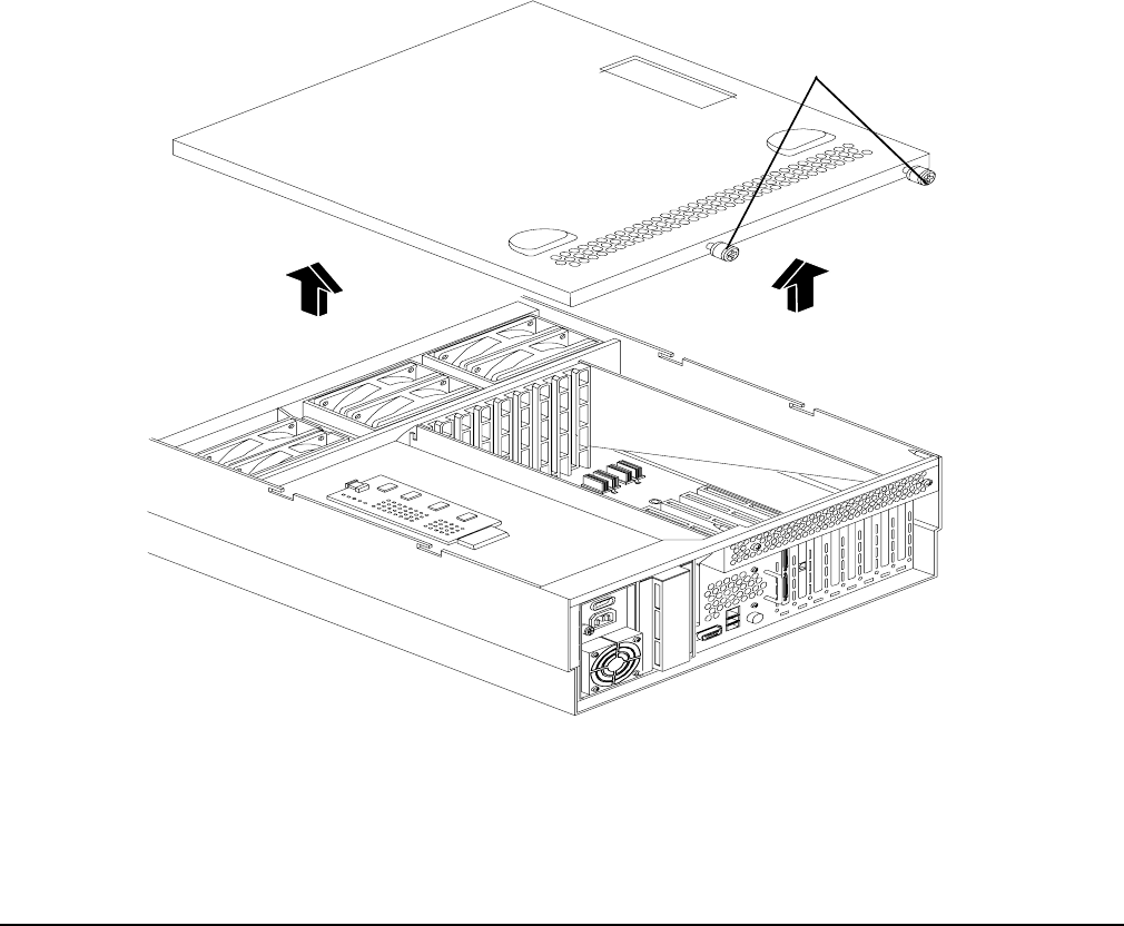
Figure 4-5. Removing and Replacing the Top Cover . . . . . . . . . . . . . . . . . . . . . . . . . . . . . . . . . . . . . 43
Figure 4-6. Opening the Memory Extender Board Latches . . . . . . . . . . . . . . . . . . . . . . . . . . . . . . . 45
Figure 4-7. Removing and Replacing the Memory Extender Board. . . . . . . . . . . . . . . . . . . . . . . . . 45
Figure 4-8. Inserting DIMM into Extender Board Slot . . . . . . . . . . . . . . . . . . . . . . . . . . . . . . . . . . . 48
Figure 4-9. 16 DIMM Extender Board Slot IDs . . . . . . . . . . . . . . . . . . . . . . . . . . . . . . . . . . . . . . . . . 49
Figure 4-10. 32 DIMM Extender Board Slot IDs . . . . . . . . . . . . . . . . . . . . . . . . . . . . . . . . . . . . . . . . 50
Figure 4-11. Opening the Processor Extender Board Latches . . . . . . . . . . . . . . . . . . . . . . . . . . . . . 53
Figure 4-12. Removing and Replacing the Processor Extender Board. . . . . . . . . . . . . . . . . . . . . . . 53
Figure 4-13. Processor Slot Locations on the Processor Extender Board . . . . . . . . . . . . . . . . . . . . . 56
Figure 4-14. Removing the Processor Sequencer . . . . . . . . . . . . . . . . . . . . . . . . . . . . . . . . . . . . . . . 57
Figure 4-15. Unlocking the Processor from the Processor Extender Board. . . . . . . . . . . . . . . . . . . 58
Figure 4-16. CPU 1 Socket Unlocked . . . . . . . . . . . . . . . . . . . . . . . . . . . . . . . . . . . . . . . . . . . . . . . . . 59
Figure 4-17. Processor Cable Routed Correctly. . . . . . . . . . . . . . . . . . . . . . . . . . . . . . . . . . . . . . . . . 60
Figure 4-18. Locking the Processor to the Processor Extender Board . . . . . . . . . . . . . . . . . . . . . . . 61
Figure 4-19. Installing Sequencer on Extender Board . . . . . . . . . . . . . . . . . . . . . . . . . . . . . . . . . . . 62
Figure 4-20. Removing and Replacing the Chassis Fans 0 and 1. . . . . . . . . . . . . . . . . . . . . . . . . . . 64
Figure 4-21. Removing and Replacing the Chassis Fan 2 . . . . . . . . . . . . . . . . . . . . . . . . . . . . . . . . . 65
Figure 4-22. I/O Baseboard Locking Lever . . . . . . . . . . . . . . . . . . . . . . . . . . . . . . . . . . . . . . . . . . . . 67
Figure 4-23. Removing the I/O Baseboard . . . . . . . . . . . . . . . . . . . . . . . . . . . . . . . . . . . . . . . . . . . . . 68
Figure 4-24. I/O Baseboard Dip Switches . . . . . . . . . . . . . . . . . . . . . . . . . . . . . . . . . . . . . . . . . . . . . 69
Figure 4-25. Slot ID Numbering . . . . . . . . . . . . . . . . . . . . . . . . . . . . . . . . . . . . . . . . . . . . . . . . . . . . . 76
Figure 4-26. PCI-X OLX Divider Layout . . . . . . . . . . . . . . . . . . . . . . . . . . . . . . . . . . . . . . . . . . . . . . 78
Figure 4-27. Inserting PCI-X Card . . . . . . . . . . . . . . . . . . . . . . . . . . . . . . . . . . . . . . . . . . . . . . . . . . . 79
Figure 4-28. Opening and Closing the OLX Divider Latch. . . . . . . . . . . . . . . . . . . . . . . . . . . . . . . . 82
Figure 4-29. Removing and Replacing the OLX Divider. . . . . . . . . . . . . . . . . . . . . . . . . . . . . . . . . . 83

Figures
12
Figure 4-30. Slot ID Numbering . . . . . . . . . . . . . . . . . . . . . . . . . . . . . . . . . . . . . . . . . . . . . . . . . . . . . 85
Figure 4-31. SCSI I/O Card Latch Location. . . . . . . . . . . . . . . . . . . . . . . . . . . . . . . . . . . . . . . . . . . . 86
Figure 4-32. Inserting SCSI I/O Card . . . . . . . . . . . . . . . . . . . . . . . . . . . . . . . . . . . . . . . . . . . . . . . . 87
Figure 4-33. LAN I/O Card Latch Location . . . . . . . . . . . . . . . . . . . . . . . . . . . . . . . . . . . . . . . . . . . . 88
Figure 4-34. Battery Location on the I/O Baseboard . . . . . . . . . . . . . . . . . . . . . . . . . . . . . . . . . . . . 89
Figure 4-35. Hard Disk Drive and Slot Locations on the Front of the Server . . . . . . . . . . . . . . . . . 91
Figure 4-36. Removing and Replacing a Hard Disk Drive in Slot 2 . . . . . . . . . . . . . . . . . . . . . . . . . 91
Figure 4-37. Installing a Volume Filler in Slot 2 . . . . . . . . . . . . . . . . . . . . . . . . . . . . . . . . . . . . . . . . 92
Figure 4-38. Removing and Replacing the SCSI Backplane Board . . . . . . . . . . . . . . . . . . . . . . . . . 94
Figure 4-39. Removing and Replacing the Midplane Riser Board . . . . . . . . . . . . . . . . . . . . . . . . . . 96
Figure 4-40. Removing and Replacing the Hot-Swap Power Supply. . . . . . . . . . . . . . . . . . . . . . . . . 99
Figure 4-41. Removing and Replacing the Power Distribution Board . . . . . . . . . . . . . . . . . . . . . . 101
Figure 4-42. Removing and Replacing the DVD Drive. . . . . . . . . . . . . . . . . . . . . . . . . . . . . . . . . . . 103
Figure 4-43. Removing and Replacing the DVD I/O Board . . . . . . . . . . . . . . . . . . . . . . . . . . . . . . 105
Figure 4-44. Removing and Replacing the Display Board . . . . . . . . . . . . . . . . . . . . . . . . . . . . . . . . 108
Figure 4-45. Removing and Replacing the QuickFind Diagnostic Board. . . . . . . . . . . . . . . . . . . . 110
Figure 5-1. Front Control Panel . . . . . . . . . . . . . . . . . . . . . . . . . . . . . . . . . . . . . . . . . . . . . . . . . . . . 117
Figure 5-2. Hot-Swap Disk Drive LED Indicators . . . . . . . . . . . . . . . . . . . . . . . . . . . . . . . . . . . . . . 118
Figure 5-3. DVD–ROM Drive . . . . . . . . . . . . . . . . . . . . . . . . . . . . . . . . . . . . . . . . . . . . . . . . . . . . . . 118
Figure 5-4. QuickFind Diagnostic Label . . . . . . . . . . . . . . . . . . . . . . . . . . . . . . . . . . . . . . . . . . . . . . 119
Figure 5-5. I/O Baseboard LEDs, Buttons and Sensors . . . . . . . . . . . . . . . . . . . . . . . . . . . . . . . . . . 121
Figure 5-6. Power Supply Status LED . . . . . . . . . . . . . . . . . . . . . . . . . . . . . . . . . . . . . . . . . . . . . . . 123
Figure 5-7. iLO MP LAN LEDs . . . . . . . . . . . . . . . . . . . . . . . . . . . . . . . . . . . . . . . . . . . . . . . . . . . . . 124
Figure 5-8. iLO MP LAN LEDs . . . . . . . . . . . . . . . . . . . . . . . . . . . . . . . . . . . . . . . . . . . . . . . . . . . . . 124
Figure C-1. EFI Boot Sequence . . . . . . . . . . . . . . . . . . . . . . . . . . . . . . . . . . . . . . . . . . . . . . . . . . . . . 162

Figures
13

Figures
14

15
About This Document
This document provides information and instructions on servicing and troubleshooting the HP Integrity
rx4640 server.
Document updates may be issued between editions to correct errors or document product changes. To ensure
that you receive the updated or new editions, you should subscribe to the appropriate product support service.
See your HP sales representative for details.
The latest version of this document can be found on the HP website at:
http://www.docs.hp.com.
Intended Audience
This document is intended to provide technical product and support information for authorized service
providers, system administrators, and HP support personnel.
This document is not a tutorial.
New and Changed Information in This Edition
This guide has been updated as follows:
• iLO 2 MP LAN Port link/activity LED display
• Removing and replacing a processor, deleted caution regarding dip switch information
• Removing an I/O board, dip switch information
• Added replacement battery part number
Publishing History
The publishing history below identifies the edition dates of this manual. Updates are made to this publication
on an unscheduled, as needed, basis. The updates will consist of a complete replacement manual and
pertinent on-line documentation.
Table 1 Publishing History Details
Document
Manufacturing
Part Number
Operating Systems
Supported Supported Product Versions Publication
Date
A6961-96013-ed2 HP-UX, Windows®,
Linux®, OpenVMS®
rx4640 November 2008
A6961-96013 HP-UX, Windows,
Linux, OpenVMS
rx4640 August 2006

16
Document Organization
This guide is divided into the following chapters.
Chapter 1 Introduction Use this chapter to learn about the features and specifications of the HP
Integrity rx4640 server.
Chapter 2 Controls, Ports, and LEDs Use this chapter to learn about the locations of the external
controls, ports, and LEDs on the server.
Chapter 3 Powering Off and Powering On the Server Use this chapter to learn about powering
the server off and on.
Chapter 4 Removing and Replacing Components Use this chapter to learn how to remove and
replace the field replaceable components (FRUs) on the server.
Chapter 5 Troubleshooting Use this chapter to learn about troubleshooting problems you may
encounter with the server.
Appendix A Parts Information Use this appendix to learn the location and part numbers of the server
components.
Appendix B Operating System Boot and Shutdown Use this appendix to learn about booting and
shutting down the operating system on the server.
Appendix C Utilities Use this appendix for information regarding the utilities available for the server.
Appendix D Console Setup and Connection Use this appendix to learn about the process for setting
up a console session and connecting to the server.
Typographic Conventions
This document uses the following conventions.
WARNING A warning lists requirements that you must meet to avoid personal injury.
CAUTION A caution provides information required to avoid losing data or avoid losing system
functionality.
NOTE A note highlights useful information such as restrictions, recommendations, or important
details about HP product features.
Book Title The title of a book. On the web and on the Instant Information CD, it may be a hot link to
the book itself.
KeyCap The name of a keyboard key or graphical interface item (such as buttons, tabs, and menu
items). Note that Return and Enter both refer to the same key.
Emphasis Text that is emphasized.
Bold Text that is strongly emphasized.
Bold The defined use of an important word or phrase.
ComputerOut Text displayed by the computer.
UserInput Commands and other text that you type.
17
Command A command name or qualified command phrase.
Option An available option.
Screen Output Example of computer screen output.
[] The contents are optional in formats and command descriptions. If the contents are a list
separated by |, you must select one of the items.
{} The contents are required in formats and command descriptions. If the contents are a list
separated by |, you must select one of the items.
... The preceding element may be repeated an arbitrary number of times.
| Separates items in a list of choices.
HP-UX Release Name and Release Identifier
Each HP-UX 11i release has an associated release name and release identifier. The uname (1) command with
the -r option returns the release identifier. This table shows the releases available for HP-UX 11i.
Related Documents
You can find other information on HP server hardware management, Microsoft® Windows®, and diagnostic
support tools in the following publications.
Website for HP Technical Documentation:
http://docs.hp.com
Server Hardware Information:
http://docs.hp.com/hpux/hw/
Windows Operating System Information
You can find information about administration of the Microsoft Windows operating system at the following
websites, among others:
•http://docs.hp.com/windows_nt/
•http://www.microsoft.com/technet/
Diagnostics and Event Monitoring: Hardware Support Tools
Complete information about HP’s hardware support tools, including online and offline diagnostics and event
monitoring tools, is at the http://docs.hp.com/hpux/diag/ website. This site has manuals, tutorials,
FAQs, and other reference material.
Table 2 HP-UX 11i Releases
Release Identifier Release Name Supported Processor Architecture
B.11.11 HP-UX 11i v1 PA-RISC
B.11.20 HP-UX 11i v1.5 Intel® Itanium®
B.11.22 HP-UX 11i v1.6 Intel Itanium
B.11.23 HP-UX 11i v2.0 Intel Itanium

18
Website for HP Technical Support:
http://us-support2.external.hp.com/
Books about HP-UX Published by Prentice Hall
The http://www.hp.com/hpbooks/ website lists the HP books that Prentice Hall currently publishes, such
as HP-UX books including:
•HP-UX 11i System Administration Handbook
http://www.hp.com/hpbooks/prentice/ptr_0130600814.html
•HP-UX Virtual Partitions
http://www.hp.com/hpbooks/prentice/ptr_0130352128.html
HP Books are available worldwide through bookstores, online booksellers, and office and computer stores.
HP Encourages Your Comments
HP encourages your comments concerning this document. We are committed to providing documentation that
meets your needs. Send errors, suggestions for improvement, or compliments to:
http://docs.hp.com/en/feedback.html (web) or
http://docsfeedback@hp.com (email address)
Include the document title, manufacturing part number, and any comment, error found, or suggestion for
improvement you have concerning this document.

Chapter 1 19
1Introduction
The HP Integrity rx4640 server is a 4-processor/8-core IPF rack-mount server based on the Itanium2
processor family architecture. The supported operating systems include HP-UX, Windows, Linux, and
OpenVMS. The server accommodates up to 32 DIMMs and internal peripherals; including two hard disk
drives, and a DVD. Its high availability features include hot-swap fans and 200-240 VAC power supplies,
hot-plug disk drives, and hot-plug PCI-X cards.
This chapter addresses the following topics:
• “Server Overview” on page 20.
• “Server Dimensions and Weight” on page 21.
• “Server Components” on page 22.
• “Supported Operating Systems” on page 24.
Introduction
Server Overview
Chapter 1
20
Server Overview
The HP Integrity rx4640 server is a 4U high Electronics Industry Association (EIA) enclosure, which mounts
in any standard 19” EIA rack. All external cabling enters and exits from the rear of the enclosure. With the
server installed in the rack, service access is enhanced by the use of chassis slides. It has bays to
accommodate 1 + 1 redundant, hot-swappable power supplies, accessible from the rear of the enclosure. There
are two low-profile hot swappable hard disk drives accessible from the front, as well as a slim-line optical
drive for a CD-R, CD-RW, DVD-R or DVD+RW. There are N + 1 redundant, hot-swappable server fans, all
clearly identified and easily accessible. Server status indication, a power switch, server locator switch and
LED are located in the front within the control panel access door on the bezel. There is also a server locator
switch and LED located on the front and back of the server for easy identification in the rack. See the HP
Integrity rx4640 Site Preparation Guide for more detailed server specifications and requirements. Figure 1-1,
Figure 1-2, and Figure 1-3 show the top, front, and rear views of the server.
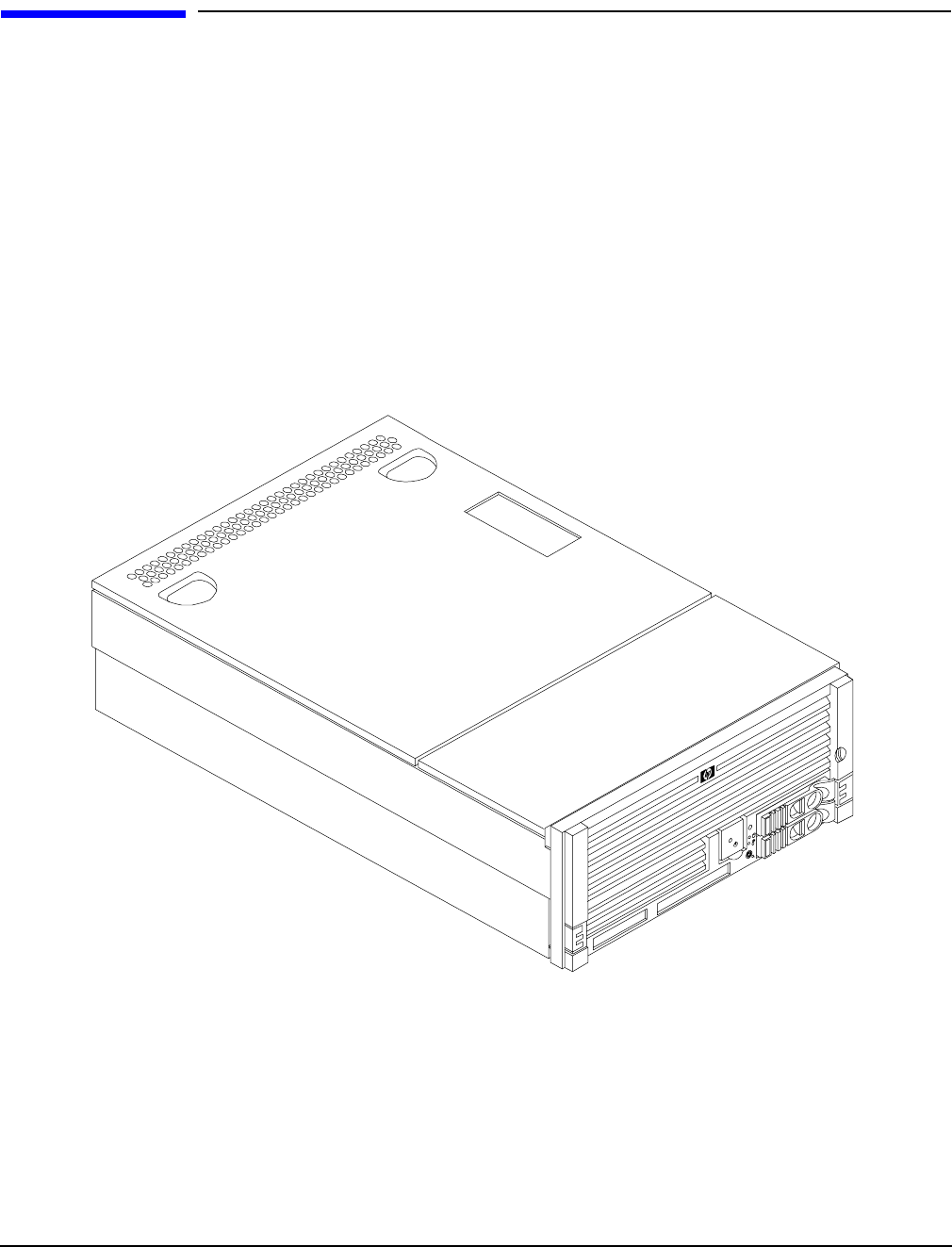
Figure 1-1 HP Integrity rx4640 Server with Front Bezel
Introduction
Server Dimensions and Weight
Chapter 1 21
Figure 1-2 HP Integrity rx4640 Server (front view with bezel removed)
Figure 1-3 HP Integrity rx4640 Server (rear view)
Server Dimensions and Weight
Table 1-1 shows the dimensions and weight of the HP Integrity rx4640 server.
Table 1-1 Server Dimensions
Dimensions Value
Height 17.46 cm (6.87 in.)
Width 44 cm (17.32 in.)
Depth (63.8 cm (25.1 in.)
Weight Unloaded - 40 kg (95 lb)
Fully loaded - 100 kg (220 lb)

Introduction
Server Components
Chapter 1
22
Server Components
The following components comprise the HP Integrity rx4640 server.
Processors
The following processors are available for the rx4640 server:
• 1.6 GHz / 18 MB cache
• 1.6 GHz / 24 MB cache
These processors are dual core processors. The processor configuration options are 1-processor/2-core (1p/2c),
2p/4c, 3p/6c, or 4p/8c.
Memory
• 16 DIMM slots on standard memory extender board
• 32 DIMM slots on optional memory extender board
• Minimum memory size of 1 GB (four 256 MB DIMMs in
• Maximum memory size of 128 GB (4 GB DIMMs on 32-slot memory extender board)
• 256 MB, 512 MB, 1 GB, 2 GB, and 4 GB standard 184 pins 2.5V DDR 200, CL2, registered, ECC
• 200 MHz memory bus frequency, 400 MTransfers/s data, 12.8 GB/s peak data bandwidth
• DIMMs loaded by quads enable interleaved mode and chip spare
PCI Riser
• Two dedicated PCI slots (LAN and SCSI)
• Four hot-plug PCI-X 66 MHz, 64-bit, 3.3V, 25W slots with shared busses and I/O. Slots 3 and 4 share a
PCI-X bus and slots 5 and 6 share a PCI-X bus
• Two hot-plug PCI-X 133 MHz 64-bit 3.3V 25W slots
Internal Core I/O
• Dual channel SCSI U320 interface, two internal 68-pin connectors, two 68-pin external connectors
• The SCSI backplane is configured as either one or two channels
• One internal IDE connector for a slim-line optical device (CD and DVD)
• No floppy connector
External Core I/O
• Three external DB-9 ports (MP local, auxiliary, remote)
• Two external USB 2.0 ports
• Two SCSI Ultra320 68-pin connectors

Introduction
Server Components
Chapter 1 23
• Two 10/100/1000Base-T ethernet LAN port
• One 10/100 integrated Lights Out Management Processor (iLO MP) LAN port
• One VGA port
Power Supply Unit
• 1200 W output power
• Redundant and hot-swap power supplies
Motherboard Manageability
• Baseboard Management Controller (BMC)
• Temperature monitoring and fans regulation by BMC
• Includes diagnostic panel LED display that shows server health
• Hardware diagnostics by BMC displayed by diagnostic panel LED
• IPMI protocol for communication between BMC/server/MP card
• Locator front/rear LEDs
• Field replacement units monitoring by BMC
Enhanced Server Manageability Using Management Processor
• LAN, telnet, and SSH console
•Web GUI
• Serial port for local console
• Serial port for modem console
• Duplication of console screen content across all consoles
Hard Disk Drives
• Two low-profile, hot-pluggable Ultra320 SCSI disk bays
• Disk options:
— 36 GB 15K RPM SCSI disk
— 73 GB 15K RPM SCSI disk
— 146 GB, 10K RPM SCSI disk
— 300 GB, 10K RPM SCSI disk
• Minimum server configuration includes one hard disk drive

Introduction
Supported Operating Systems
Chapter 1
24
Supported Operating Systems
The following operating systems are supported on the entry-class HP Integrity servers:
•HP-UX 11i Version 2 (B.11.23)
•HP OpenVMS I64
•Microsoft® Windows® Server 2003
•Red Hat Enterprise Linux 4
•SuSE Linux Enterprise Server 10
For more operating system information, see Appendix B, “Booting the Operating System,” on page 141.

Chapter 2 25
2Controls, Ports, and LEDs
This chapter describes the controls, ports, and LEDs found on the front panel, rear panel, and internal
locations of the HP Integrity rx4640 server.
This chapter addresses the following topics:
• “Front Panel Controls, Ports, and LEDs” on page 26.
• “Rear Panel Controls, Ports, and LEDs” on page 28.
• “Internal Controls, Ports, and LEDs” on page 31.
Controls, Ports, and LEDs
Front Panel Controls, Ports, and LEDs
Chapter 2
26
Front Panel Controls, Ports, and LEDs
The front panel of the HP Integrity rx4640 server provides the controls and indicators commonly used for
operation. Figure 2-1, Figure 2-2, and Figure 2-3 show the controls, ports, and LEDs on the front panel and
control panel.
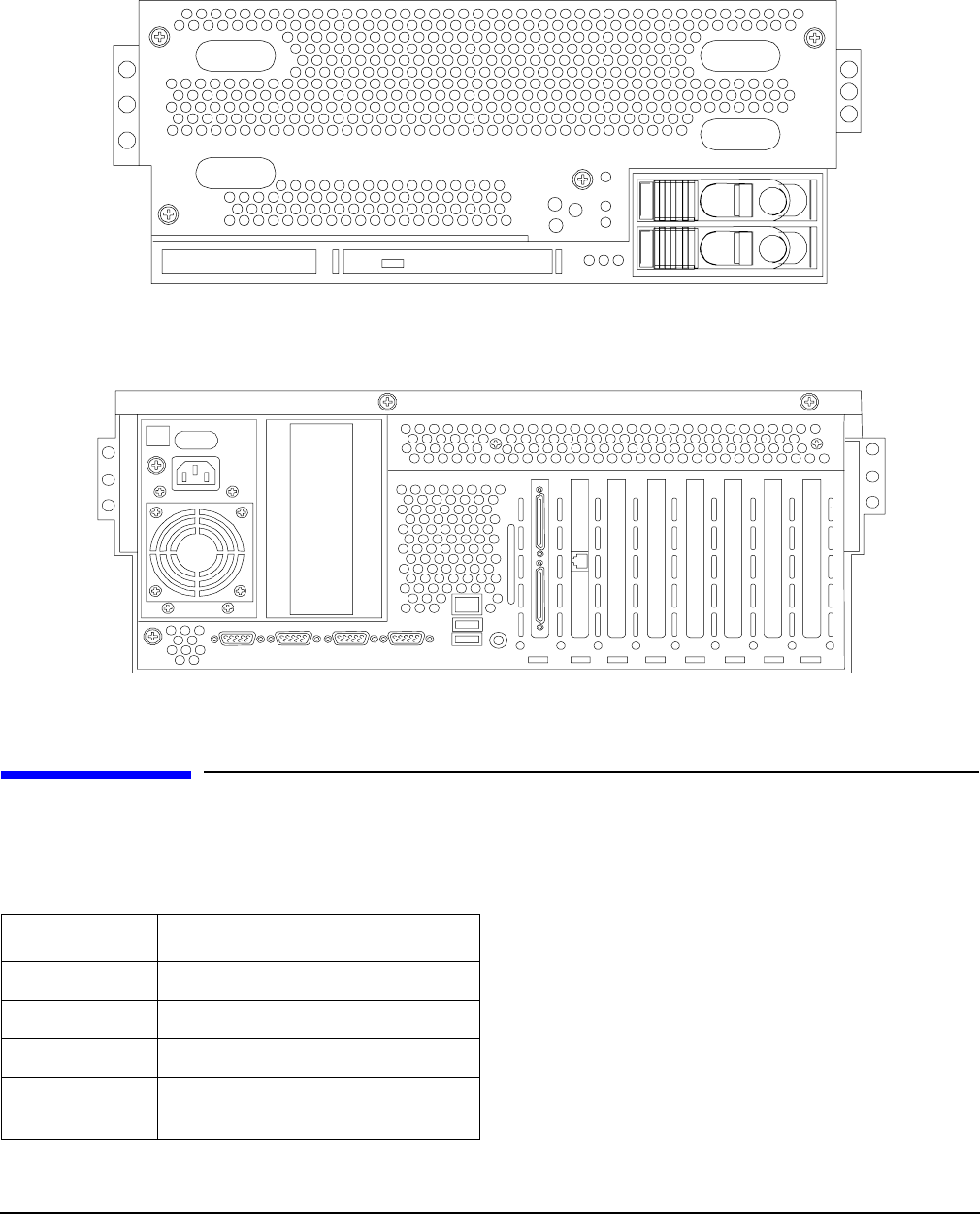
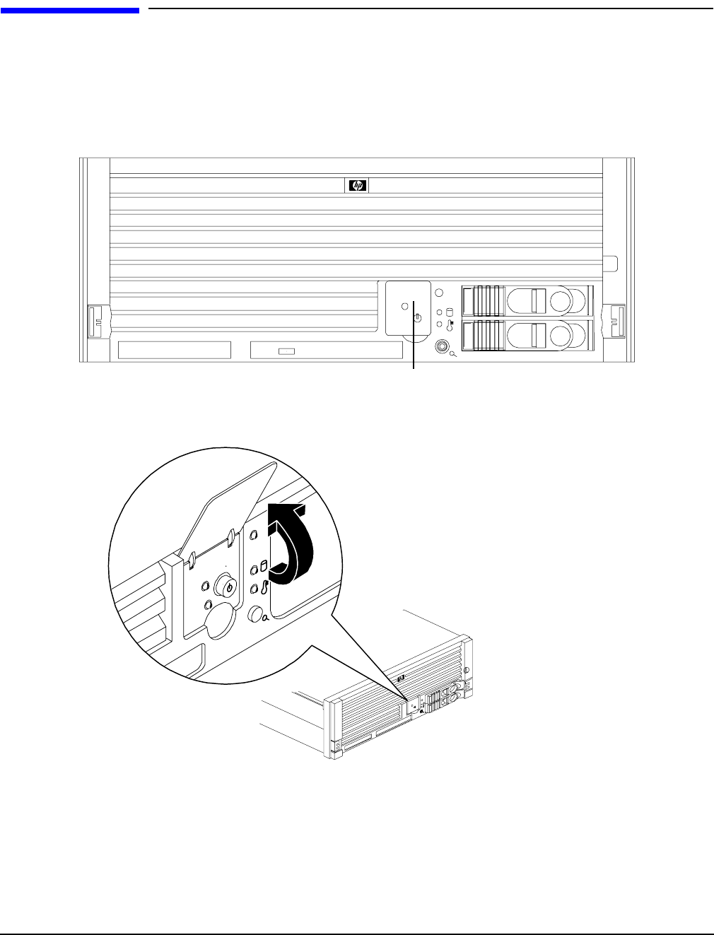
Figure 2-1 Front View with Bezel
Figure 2-2 Accessing the Control Panel
Control Panel
Controls, Ports, and LEDs
Front Panel Controls, Ports, and LEDs
Chapter 2 27
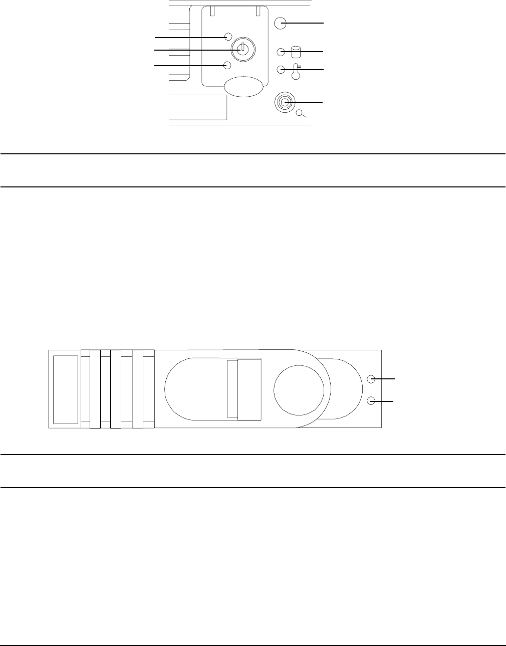
Figure 2-3 Control Panel LEDs
NOTE For troubleshooting information regarding control panel LEDs, see “Front Control Panel LED
Indicators” on page 117.
Hard Disk Drive LED Indicators
The hot-swap disk drives have two LEDs per drive, as described below. Figure 2-4 shows the hard disk drive
LEDs.
• Status LED - The drive status LED displays green when disk power is on, and is off when disk power is
off.
• Activity LED - The drive activity LED is green and indicates disk drive activity. This LED is controlled by
the disk drive directly and turns on when a drive is accessed.
Figure 2-4 Hard Disk Drive LED Indicators
NOTE For troubleshooting information regarding the hard disk drive LEDs, see “Hard Disk Drive
LED Indicators” on page 118.
Power LED
Power button
ToC/NMI button
Server LED
Disk LED
Thermal LED
Locator
button/LED
Status LED
Activity LED
Controls, Ports, and LEDs
Rear Panel Controls, Ports, and LEDs
Chapter 2
28
DVD/DVD-R/DVD-RW Drives
The HP server is delivered with one DVD drive (DVD-R and DVD-RW optional). Each of these devices has one
activity LED. Figure 2-5 shows the location of the DVD LEDs.
Figure 2-5 DVD–ROM Drive
NOTE For troubleshooting information regarding the DVD LEDs, see “DVD/DVD-R/DVD-RW Drive
LED Indicators” on page 118.
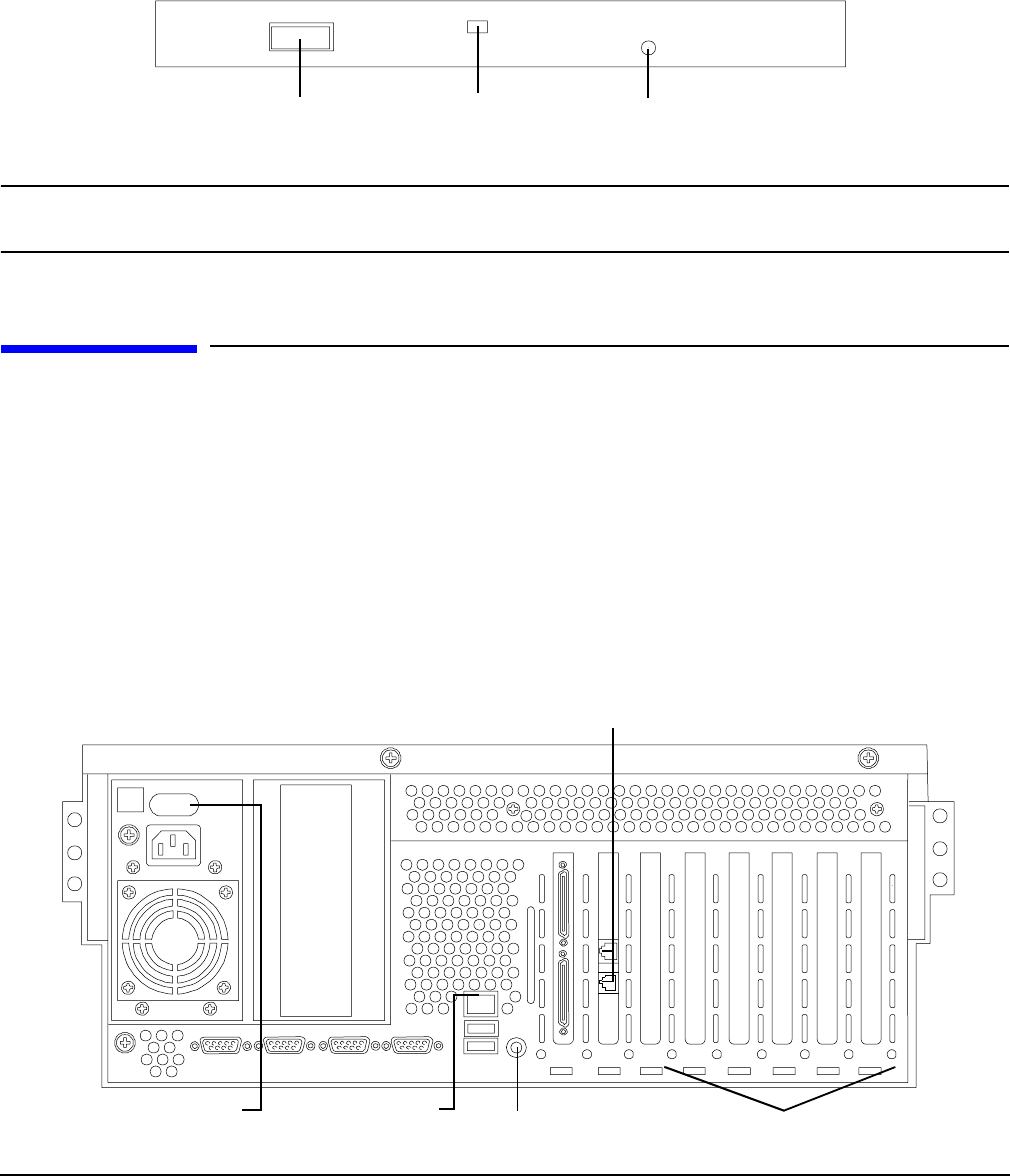
Rear Panel Controls, Ports, and LEDs
The HP server rear panel includes communication ports, I/O ports, ac power connectors, two power supply
bays, attention LED indicators for the hot-plug PCI boards, and the locator LED/button. Figure 2-6 shows the
LEDs located on the rear panel of the HP server. They include the:
• Power supplies
• MP LAN
• 2 port Gigabit ethernet card LAN
•PCI slots 3-8
Figure 2-6 Rack Mount and Pedestal Rear View
Eject Button Activity LED Emergency Eject
Gigabit Ethernet LAN ports
MP LAN LEDs 6 PCI attention LEDs
Locator button/LED
Power supply LEDs
Controls, Ports, and LEDs
Rear Panel Controls, Ports, and LEDs
Chapter 2 29
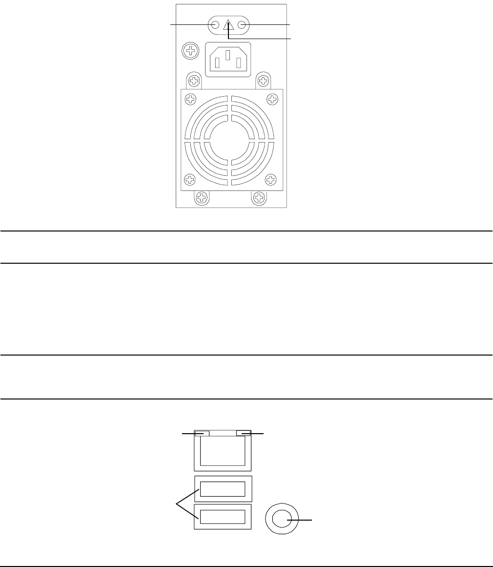
Power Supply Status LEDs
Each 200-240 VAC power supply unit has three status LEDs located on the power supply accessible from the
rear panel. Consolidated status of all power supplies is reported by the front control panel by the power status
LED. Figure 2-7 shows the location of the power supply status LEDs on the rear of the enclosure.
Figure 2-7 Power Supply Status LEDs
NOTE For troubleshooting information regarding the power supply status LEDs, see “Power Supply
Status LED Indicators” on page 123.
Management Processor LAN LEDs
The internal Management Processor (MP) LAN uses an RJ-45 type connector. This connector has two LEDs
(LAN link and LAN activity) that signal status and activity. Figure 2-8 shows the MP LAN LEDs and USB
ports on the rear panel of the server.
NOTE Two versions of the iLO MP card exist for this server. Depending on which version of the card is
installed in the server, the iLO MP LAN port LEDs display differently. For more information,
see “iLO MP LAN Port Link/Activity LED Display” on page 123.
Figure 2-8 MP LAN LEDs
Predict fail
LED-amber Power LED-green
Fail LED-amber
100M Link/Activity, Amber LED 10M Link/Activity, Green LED
Locator Button and LED
USB Ports
Controls, Ports, and LEDs
Rear Panel Controls, Ports, and LEDs
Chapter 2
30
NOTE For troubleshooting information regarding the iLO MP LAN LEDs, see “iLO MP LAN Port
Link/Activity LED Display” on page 123.
Locator LED and Button
An LED and button is provided on the rear panel of the server. Another single blue LED and button is on the
front control panel that enables/disables the locator function. See Figure 2-8 for the location of the locator
button.
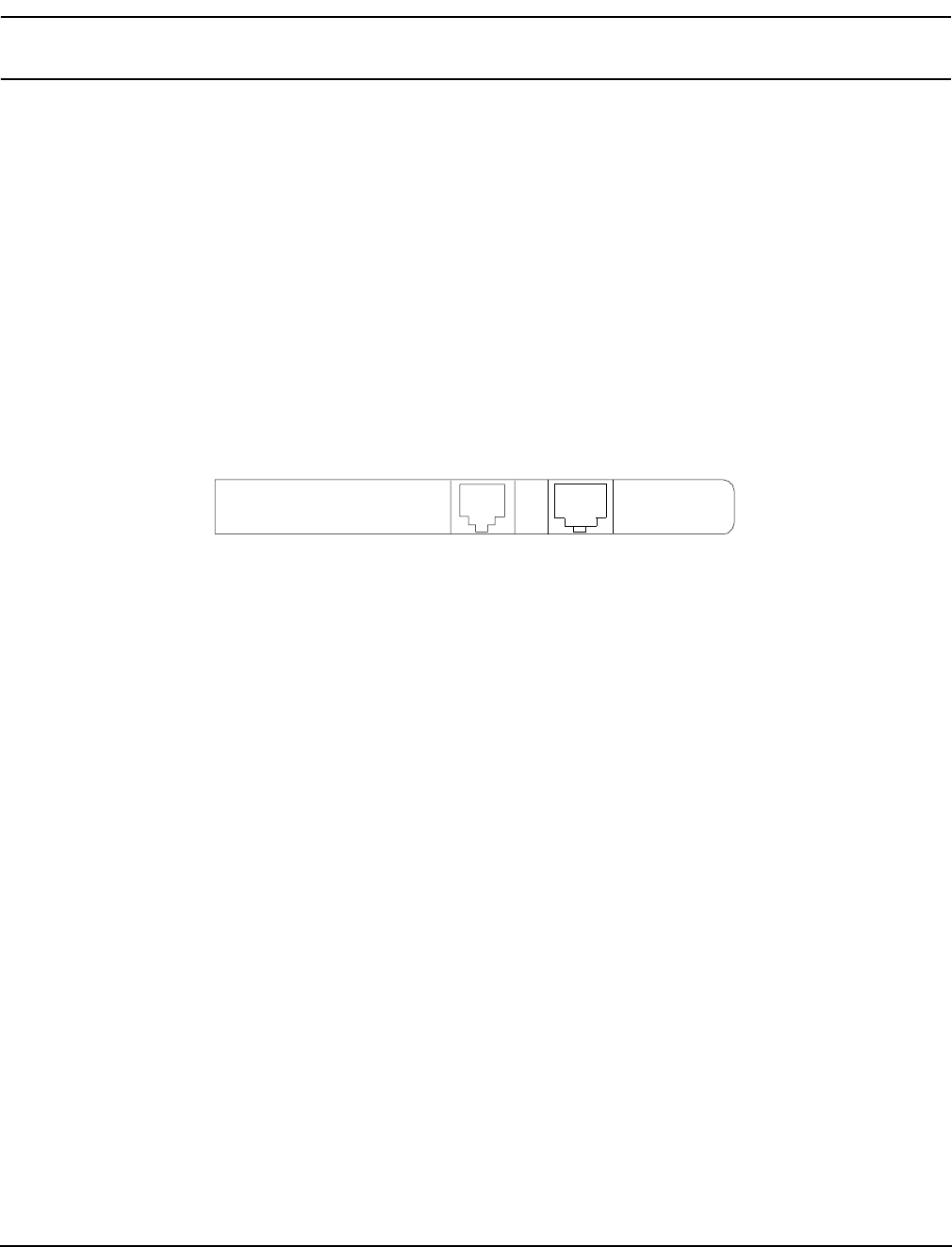
Gigabit Ethernet Card LAN Ports (Core I/O)
The 2-Port core I/O Gigabit ethernet card uses two RJ-45 LAN connectors. These connectors have no LEDs.
Figure 2-9 shows the two core I/O LAN ports.
Figure 2-9 Core I/O LAN Port LEDs
RJ-45 Connectors
Controls, Ports, and LEDs
Internal Controls, Ports, and LEDs
Chapter 2 31
Internal Controls, Ports, and LEDs
The HP Integrity rx4640 server contains internal controls, switches, and LEDs inside the server. This
includes a diagnostic LED panel located under the top panel; and reset buttons, switches, and LEDs located
on the I/O baseboard.
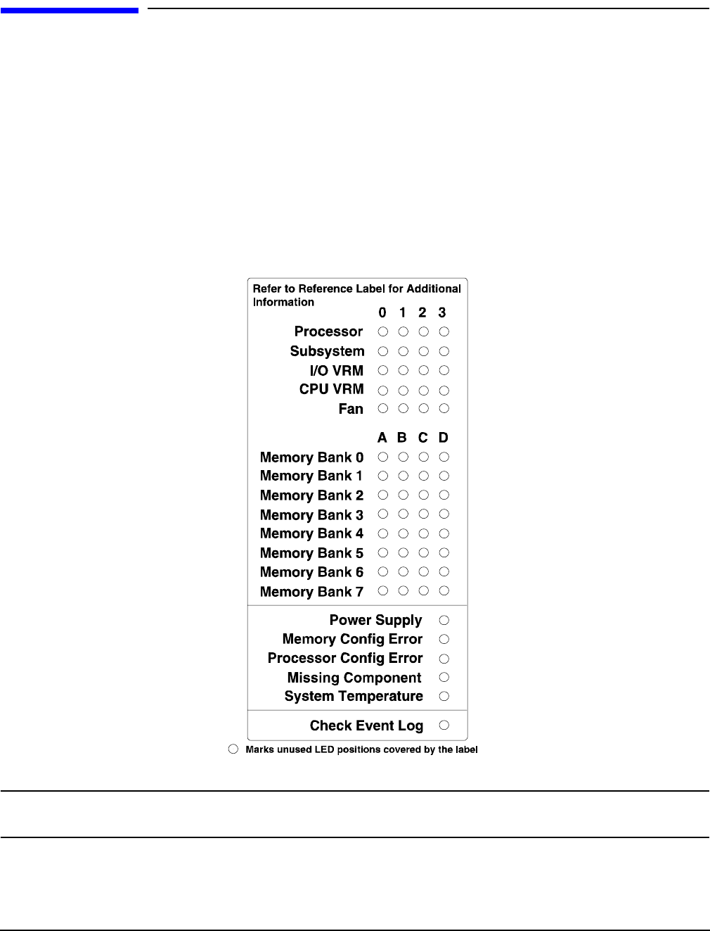
QuickFind Diagnostic Panel
The QuickFind diagnostic panel has 58 single color LEDs and one multi-color LED for temperature. The
LEDs are normally off. The appropriate LED is turned on when an error is detected or a replacement part is
required. You can access the QuickFind diagnostic panel by removing the top cover. See “Removing the Top
Cover” on page 43. Figure 2-10 shows the QickFind diagnostic panel LEDs.
Figure 2-10 QuickFind Diagnostic Panel
NOTE For a complete description of QuickFind diagnostic LED states, see “QuickFind Diagnostic
Panel LED Indicators” on page 119.
Controls, Ports, and LEDs
Internal Controls, Ports, and LEDs
Chapter 2
32
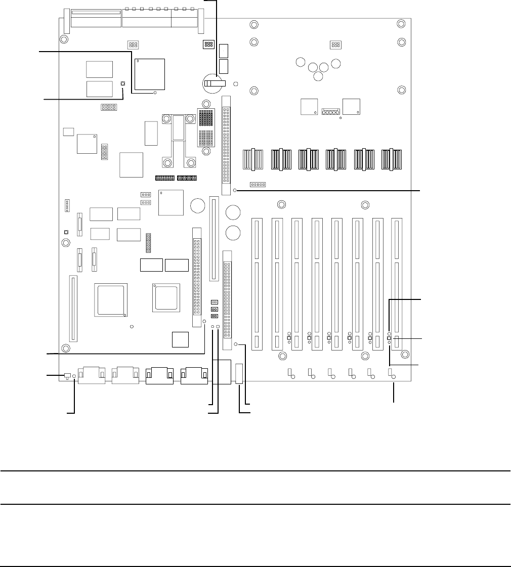
I/O Baseboard LED Indicators
There are various LEDs, sensors, reset, and attention buttons located on the HP Integrity rx4640 server I/O
baseboard. They are shown in Figure 2-11.
Figure 2-11 I/O Baseboard LEDs, Buttons, and Sensors
NOTE For a complete description of the baseboard LEDs, see “I/O Baseboard LED Indicators” on
page 121.
PCI attention
LED
6X
PCI attention
button (doorbell)
6X
PCI power LED
6X
PCI attention LED
6X
3.3VSB
power
LED
BMC
reset
button
12V VRM LED
3.3V VRM LED
locator button/LED
5V VRM
LED
MP soft
reset
button
MP self-test
LED
MP heartbeat LED
BMC heartbeat LED
Battery

Chapter 3
Powering Off and Powering On the Server
Power States
34
Power States
The server has three power states:
•Standby power
•Full power
•Off
Plug the power cord into the appropriate receptacle on the rear of the chassis to achieve the standby power
state; the front panel power button is not turned on. Full power occurs when the power cord is plugged into
the appropriate receptacle, and either the power is activated through the iLO MP PC command, or the power
button is activated. In the off state, the power cords are not plugged in. Table 3-1 lists the server power states.
NOTE If the power restore feature is set to Always On through the iLO MP PR command, the server
automatically powers on to the full power state.
Powering Off the Server
Power off the server using the following methods if the server is in either the standby or full power state:
•iLO MP PC command
• Power button
Powering Off the Server Using the iLO MP
To power off the server through the iLO MP, follow these steps:
Step 1. Gracefully shut down the operating system. See Appendix B, “Booting the Operating System,” on
page 141, or your operating system documentation for more information.
Step 2. Initiate a console session, and access the iLO MP Main Menu.
Step 3. Enter CM to access the Command Menu.
Table 3-1 Power States
Power States
Power Cable
Plugged Into
Receptacle?
Power Activated through the
iLO MP PC Command; or
Front Panel Power Button
Activated?
AC Voltage
Applied
DC Voltage
Applied
Standby power Yes No Yes No
Full power Yes Yes Yes Yes
Off No No No No

Chapter 3
Powering Off and Powering On the Server
Powering On the Server
35
Step 4. Enter PC to use the remote power control command.
Step 5. Enter OFF to power off the server, and enter YES when prompted to confirm the action.
IMPORTANT The main dc voltage is now removed from the server; however, ac voltage for standby
power is still present in the server.
Step 6. Unplug all power cables from the receptacles on the rear panel of the server.
Powering Off the Server Manually
Manually power off the server through the power button by following these steps:
Step 1. Gracefully shut down the operating system. See Appendix B, “Booting the Operating System,” on
page 141, or your operating system documentation for more information.
Step 2. Press the power button to power off the server.
IMPORTANT The main dc voltage is now removed from the server; however, ac voltage for standby
power is still present in the server.
Step 3. Unplug all power cables from the receptacles on the rear panel of the server.
Powering On the Server
Power on the server to full power using the following methods if the server is in the standby power state:
•iLO MP PC command
• Power button
Powering On the Server Using the iLO MP
NOTE If the power restore feature is set to Always On through the iLO MP PR command, the server
may automatically power on to the full power state.
To power on the server through the iLO MP, follow these steps:
Step 1. Plug all power cables into the receptacles on the rear panel of the server.
Step 2. Initiate a console session, and access the iLO MP Main Menu.
Step 3. Enter CM. to enable command mode.
Step 4. Enter PC to use the remote power control command.
Step 5. Enter ON to power on the server, and enter YES when prompted to confirm the action.

Chapter 3
Powering Off and Powering On the Server
Powering On the Server
36
Step 6. Start the operating system. See Appendix B, “Booting the Operating System,” on page 141, or your
operating system documentation for more information.
Powering On the Server Manually
NOTE If the power restore feature is set to Always On through the iLO MP PR command, the server
may automatically power on to the full power state.
To manually power on the server, follow these steps:
Step 1. Plug all power cables into the receptacles on the rear panel of the server.
Step 2. Press the power button to start the server.
Step 3. Start the operating system. See Appendix B, “Booting the Operating System,” on page 141, or your
operating system documentation for more information.

Chapter 4 37
4Removing and Replacing Components
This chapter describes the procedure for removing and replacing the different components in the HP Integrity
rx4640 server.
This chapter addresses the following topics:
• “Safety Information” on page 38
• “Service Tools Required” on page 38
• “Accessing a Rack Mounted Server” on page 38
• “Accessing a Pedestal Mounted Server” on page 40
• “Removing and Replacing the Front Bezel” on page 41
• “Removing and Replacing the Front and Top Covers” on page 42
• “Removing and Replacing the Memory Extender Board” on page 44
• “Removing and Replacing Server Memory DIMMs” on page 46
• “Removing and Replacing the Processor Extender Board” on page 52
• “Removing and Replacing a Processor” on page 55
• “Removing and Replacing Hot-Swap Chassis Fans” on page 63
• “Removing and Replacing the I/O Baseboard” on page 66
• “Removing and Replacing Hot-Plug PCI-X Cards” on page 71
• “Removing and Replacing OLX Dividers” on page 81
• “Removing and Replacing Core I/O Cards” on page 85
• “Removing and Replacing the Server Battery” on page 89
• “Removing and Replacing Hard Disk Drives” on page 90
• “Removing and Replacing the SCSI Backplane Board” on page 93
• “Removing and Replacing the Midplane Riser Board” on page 95
• “Removing and Replacing the Power Supplies” on page 98
• “Removing and Replacing the Power Distribution Board” on page 100
• “Removing and Replacing the DVD Drive” on page 102
• “Removing and Replacing the DVD I/O Board” on page 104
• “Removing and Replacing the Display Board” on page 107
• “Removing and Replacing the QuickFind Diagnostic Board” on page 109

Chapter 4
Removing and Replacing Components
Safety Information
38
Safety Information
Follow the procedures listed below to ensure safe handling of components and to prevent harm to both you
and the HP server:
• Use an antistatic wrist strap and a grounding mat, such as those included in the Electrically Conductive
Field Service Grounding Kit (HP 9300-1155).
• Handle accessory boards and components by the edges only. Do not touch any metal-edge connectors or
any electrical components on accessory boards.
• Do not wear clothing subject to static charge build-up, such as wool or synthetic materials.
WARNING Hazardous voltages are present inside the HP server. Always remove ac power
from the server and associated assemblies while working inside the unit. Serious
injury may result if this warning is not observed.
Service Tools Required
Service of this product may require one or more of the following tools:
• Electrically conductive field service kit (P/N 9300-1155)
• 1/4 inch flat blade screwdriver
• ACX-15 torx screwdriver
• ACX-25 torx screwdriver
Accessing a Rack Mounted Server
The HP Integrity rx4640 server is designed to be rack mounted. The following procedure explains how to gain
access to your HP Integrity rx4640 server that is mounted in an approved rack. For rack installation
instructions, review the document titled Installation Guide, Mid-Weight Slide Kit, 5065-7291. This document
can be accessed at: http://www.hp.com/racksolutions.
WARNING Ensure that all anti-tip features (front and rear anti-tip feet installed; adequate
ballast properly placed; and so on) are employed prior to extending the server.
Chapter 4
Removing and Replacing Components
Accessing a Rack Mounted Server
39
Extending the Server from the Rack
NOTE Ensure that there is enough area (Approximately 1.5 meters [4.5 ft.]) to fully extend the server
out the front and work on it.
To extend the server from the rack, follow these steps:
Step 1. Remove the T-25 screws that fasten the server to the rack. See Figure 4-1, “Accessing 25MM Torx
Screws.”
Step 2. Flip out the two pull handles at either end of the front bezel and slowly pull the unit forward by the
handles. The server is fully extended when the rail clips are locked in place. When fully extended,
the front and top covers are fully accessible.
Figure 4-1 Accessing 25MM Torx Screws
Inserting the Server into the Rack
To insert the server into the rack, follow these steps:
Step 1. Press the rail clips on either side of the server inward and push the server into the rack until it
stops.
Step 2. Replace the T-25 screws that fasten the server to the rack.
25MM Torx
screw 2X
Chapter 4
Removing and Replacing Components
Accessing a Pedestal Mounted Server
40
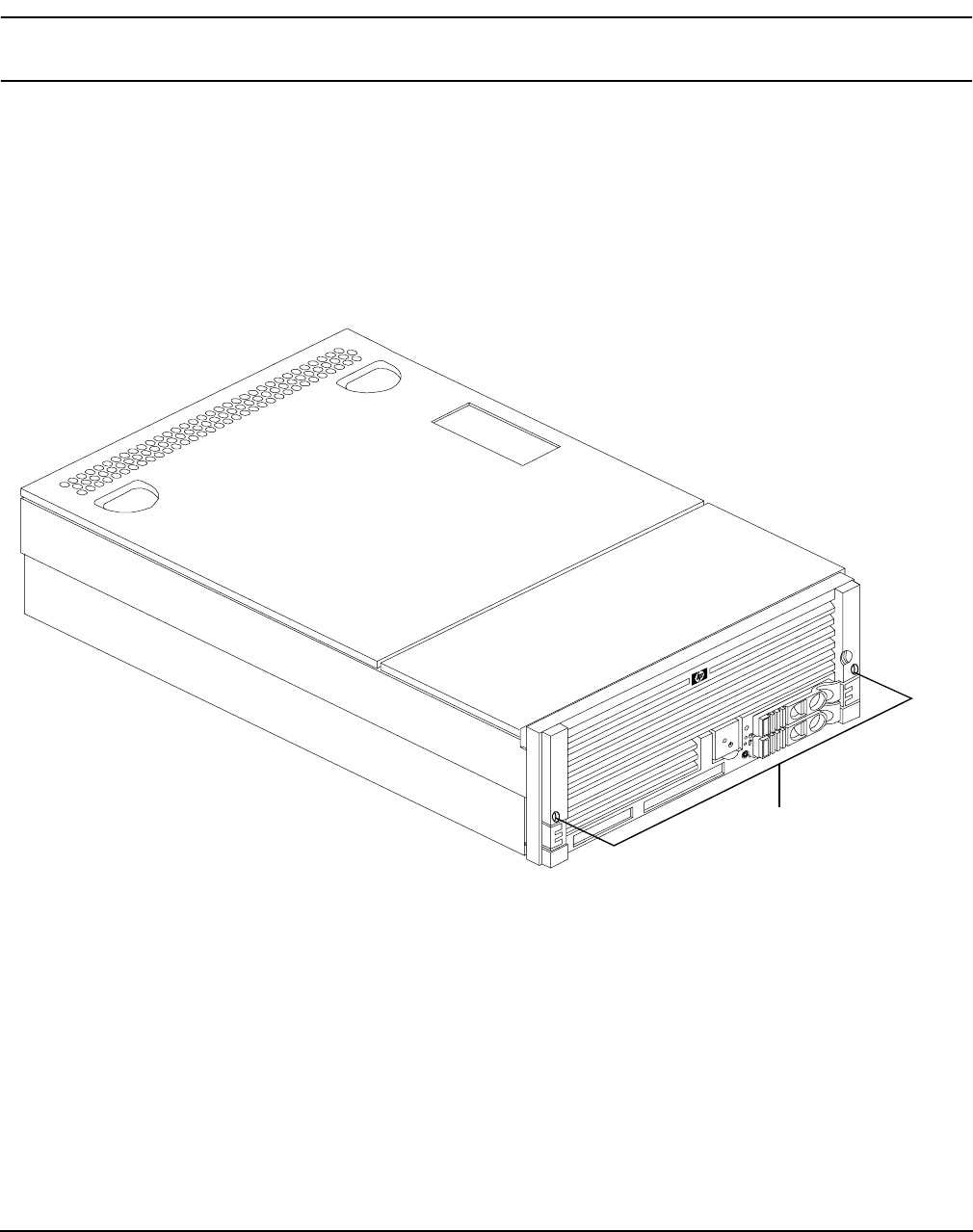
Accessing a Pedestal Mounted Server
The HP Integrity rx4640 server is also designed to be pedestal mounted. You do not need to remove the
pedestal from the HP server to gain access to internal components. The front bezel, front cover, and top cover
may be removed with the pedestal attached to the HP server.
WARNING Ensure that the HP server is properly grounded when performing
remove-and-replace procedures. Use an antistatic wrist strap and grounding mat
similar to those found in the HP Electrically Conductive Field Service Kit.
Figure 4-2 Pedestal Mounted HP Integrity rx4640 Server
Chapter 4
Removing and Replacing Components
Removing and Replacing the Front Bezel
41
Removing and Replacing the Front Bezel
The server does not have to be turned off to remove the front bezel. Figure 4-3 shows how to remove the front
bezel.
Figure 4-3 Removing and Replacing the Front Bezel
Removing the Front Bezel
To remove the front bezel, perform the following step:
Step 1. Grasp the front bezel at the outer edges and pull straight out.
Replacing the Front Bezel
To replace the front bezel, perform the following step:
Step 1. Push the front bezel straight into the chassis until it snaps into place.
Chapter 4
Removing and Replacing Components
Removing and Replacing the Front and Top Covers
42
Removing and Replacing the Front and Top Covers
The following procedures detail how to remove and replace the front and top covers of the HP Integrity
rx4640 server. Figure 4-4 shows how to remove the front cover.
NOTE When the front or top cover is removed the chassis fan units increase to high speed to assist
cooling. When the top cover is replaced at the end of the operation, the chassis fans return to
normal speed.
Figure 4-4 Removing and Replacing the Front Cover
Removing the Front Cover
To remove the front cover, follow these steps:
Step 1. If rack mounted, slide the HP server out from the rack until it stops. See “Extending the Server
from the Rack” on page 39.
Step 2. Remove the front bezel. See “Removing the Front Bezel” on page 41.
Step 3. Using a torx T15 driver, loosen the four captive thumbscrews that hold the front cover in place.
Step 4. Raise the cover slightly, and pull the cover toward the front of the server to free the tabs from the
slots in the chassis.
Thumbscrews
Slots
Slots
Chapter 4
Removing and Replacing Components
Removing and Replacing the Front and Top Covers
43
Replacing the Front Cover
To replace the front cover, follow these steps:
Step 1. Align the tabs at the rear of the front cover with the corresponding slots in the chassis and fully
seat the tabs into the slots. Figure 4-4 shows how to install the front cover.
Step 2. Tighten the four thumbscrews securely.
Step 3. Replace the front bezel. See “Replacing the Front Bezel” on page 41.
Step 4. If rack mounted, slide the HP server into the rack until it stops. See “Inserting the Server into the
Rack” on page 39.
Removing the Top Cover
To remove the top cover, follow these steps:
Step 1. If rack mounted, slide the HP server out from the rack until it stops. See “Extending the Server
from the Rack” on page 39.
Figure 4-5 Removing and Replacing the Top Cover
Step 2. Loosen the two captive thumbscrews that hold the top cover in place.
Step 3. Pull the cover toward the rear of the server to free the tabs from the slots in the chassis and lift it
straight up.
Thumbscrews

Chapter 4
Removing and Replacing Components
Removing and Replacing the Memory Extender Board
44
Replacing the Top Cover
To replace the top cover, follow these steps:
Step 1. Align the tabs at the rear of the top cover with the corresponding slots in the chassis, fully seat the
tabs into the slots, and push forward until it seats.
Step 2. Using a torx T15 driver, tighten the two thumbscrews securely.
Step 3. If rack mounted, slide the HP server into the rack until it stops. See “Inserting the Server into the
Rack” on page 39.
Removing and Replacing the Memory Extender Board
The memory extender board is located directly under the front cover of the chassis. The standard memory
extender board can hold up to 16 DIMMs. The high capacity memory extender board can hold up to 32
DIMMs.
WARNING Ensure that the server is powered down and all power sources have been
disconnected from the server prior to removing or replacing a memory extender
board.
Voltages are present at various locations within the server whenever an ac power
source is connected. This voltage is present even when the main power switch is in
the off position.
Failure to observe this warning could result in personal injury or damage to
equipment.
CAUTION Observe all ESD safety precautions before attempting this procedure. Failure to follow ESD
safety precautions could result in damage to the server.
Removing the Memory Extender Board
To remove a memory extender board, follow these steps:
Step 1. If rack mounted, slide the HP server out from the rack until it stops. See “Extending the Server
from the Rack” on page 39.
NOTE If desired, the memory extender board may be removed without removing the HP
server from the rack.
Step 2. Remove the front bezel from the chassis. See “Removing the Front Bezel” on page 41.
Step 3. Remove the front cover from the chassis. See “Removing the Front Cover” on page 42.
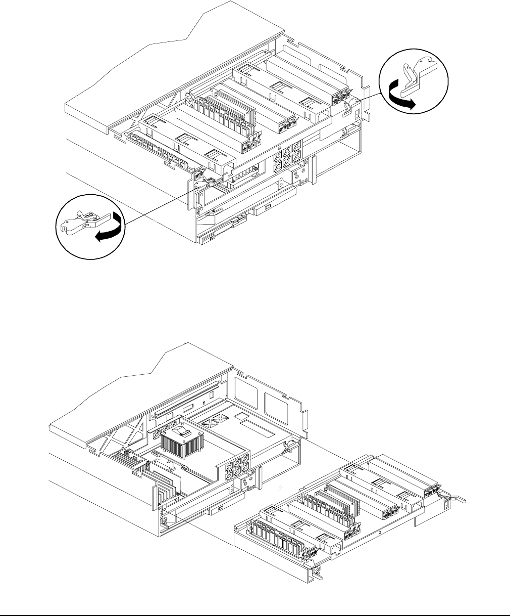
Chapter 4
Removing and Replacing Components
Removing and Replacing the Memory Extender Board
45
Step 4. Press each latch on the two extraction levers located on each side of the memory extender board.
Figure 4-6 shows how to unlatch the memory extender board.
Figure 4-6 Opening the Memory Extender Board Latches
Step 5. Pull on the extraction levers to unplug the memory extender board from the socket located on the
midplane riser board and remove the memory extender board from the chassis. Figure 4-7 shows
how to remove the memory extender board from the server.
Figure 4-7 Removing and Replacing the Memory Extender Board

Chapter 4
Removing and Replacing Components
Removing and Replacing Server Memory DIMMs
46
Replacing the Memory Extender Board
To replace the memory extender board, follow these steps:
Step 1. Ensure the extraction levers are positioned in the outward, unlocked position. Figure 4-7 shows
how to install the memory extender board.
Step 2. Align the memory extender board with the front and rear chassis guide slots.
Step 3. Slide the memory extender board in until it begins to seat in the socket located on the midplane
board.
Step 4. Push the extraction levers inward to the locked position in order to plug in the memory extender
board into the midplane riser board.
Step 5. Replace the front cover. See “Replacing the Front Cover” on page 43.
Step 6. Replace the front bezel. See “Replacing the Front Bezel” on page 41.
Step 7. If rack mounted, slide the HP server into the rack until it stops. See “Inserting the Server into the
Rack” on page 39.
Removing and Replacing Server Memory DIMMs
Use these procedures to remove and replace server memory DIMMs. server memory DIMMs are located on
the memory extender board.
WARNING Ensure that the server is powered down and all power sources have been
disconnected from the server prior to removing or replacing server memory DIMMs.
Voltages are present at various locations within the server whenever an ac power
source is connected. This voltage is present even when the main power switch is in
the off position.
Failure to observe this warning could result in personal injury or damage to
equipment.
CAUTION Observe all ESD safety precautions before attempting this procedure. Failure to follow ESD
safety precautions could result in damage to the server.
Removing Server Memory DIMMs
To remove server memory, follow these steps:
Step 1. If rack mounted, slide the HP server out from the rack until it stops. See “Extending the Server
from the Rack” on page 39.

Chapter 4
Removing and Replacing Components
Removing and Replacing Server Memory DIMMs
47
NOTE If desired, the processor extender board may be removed without removing the HP
server from the rack.
Step 2. Remove the front bezel. See “Removing the Front Bezel” on page 41.
Step 3. Remove the front cover. See “Removing the Front Cover” on page 42.
Step 4. Remove the memory extender board. See “Removing the Memory Extender Board” on page 44.
Step 5. Identify the DIMM to be removed and push the appropriate extraction levers found on either side of
the DIMM slot outward to the open position. The DIMM ejects from the slot.
Step 6. Remove the DIMM from the socket.
Installing Memory DIMMs
Your HP Integrity rx4640 comes with a 16 DIMM memory extender board that is minimally configured with
1GB of memory (four 256 Mb DIMMs loaded in quad 0 [slots 0A, 0B, 0C, and 0D]). See Figure 4-9 for the slot
locations on the 16 DIMM memory extender board.
An optional 32 DIMM memory extender board is available to replace the 16 DIMM memory extender board
and must also be minimally configured with 1 GB in quad 0. See Figure 4-10 for the slot locations on the 32
DIMM memory extender board.
You may insert additional DIMMs into both 16 and 32 DIMM boards. When adding DIMMs, you must use a
minimum of four like sized DIMMs in the next available quad. DIMMs must be loaded in quads with qualified
modules. Memory is protected by data ECC, and the hardware implementation supports chip-spare.
Supported DIMM Sizes
Supported DIMM sizes are 256 MB, 512 MB, 1 GB, 2 GB, or 4 GB. Dissimilar DIMM sizes may be used across
the entire extender board but all four DIMMs in each quad must match. For cooling purposes, DIMM fillers
must be used in some unused slots.
DIMM Slot Fillers
Both the 16 and 32 DIMM extender boards have DIMM slot filler boards placed over all unfilled DIMM slots.
As you fill DIMM quads with additional memory you must remove the DIMM slot fillers covering the affected
slots. All remaining DIMM fillers in unused slots must remain in place to maximize internal cooling. See
Table 4-2 and Table 4-4 for slot filler requirements for the 16 and 32 DIMM memory extender boards.
NOTE One DIMM filler board covers two adjacent DIMM slots. As a general rule, only remove DIMM
slot fillers as you add memory and the correct configuration will always remain.
Installing DIMMs
To install DIMMs, follow these steps:
Step 1. Align the DIMM with the socket located on the memory extender board.
Step 2. Gently and evenly push on each side of the DIMM until it seats in the socket. Ensure that the
extraction levers are in the closed position. Repeat as needed until all additional DIMMs are
installed.
Step 3. Replace the memory extender board. See “Replacing the Memory Extender Board” on page 46.
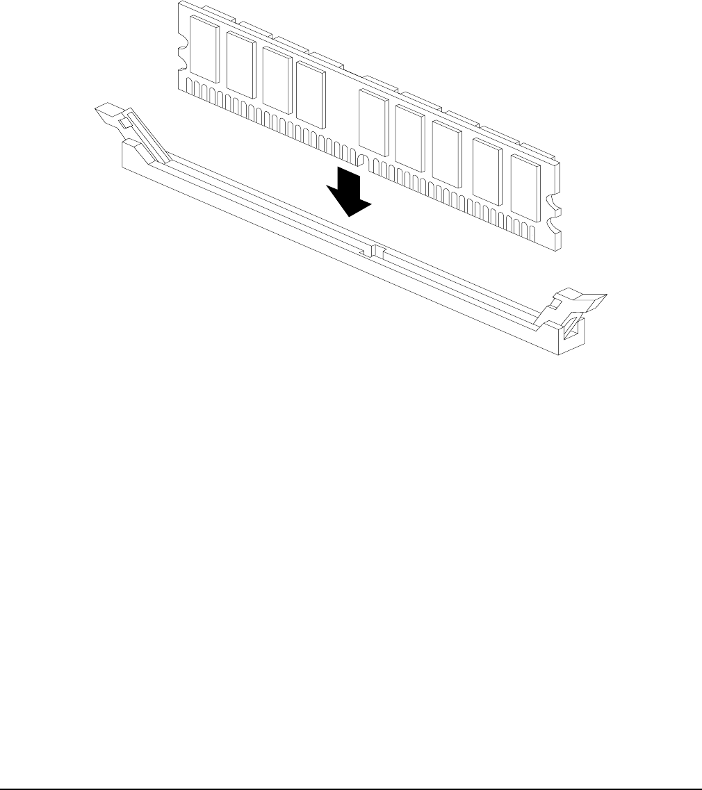
Chapter 4
Removing and Replacing Components
Removing and Replacing Server Memory DIMMs
48
Step 4. Replace the front cover. See “Replacing the Front Cover” on page 43.
Step 5. Replace the front bezel. See “Replacing the Front Bezel” on page 41.
Step 6. If rack mounted, slide the HP server into the rack until it stops. See “Inserting the Server into the
Rack” on page 39.
Figure 4-8 Inserting DIMM into Extender Board Slot
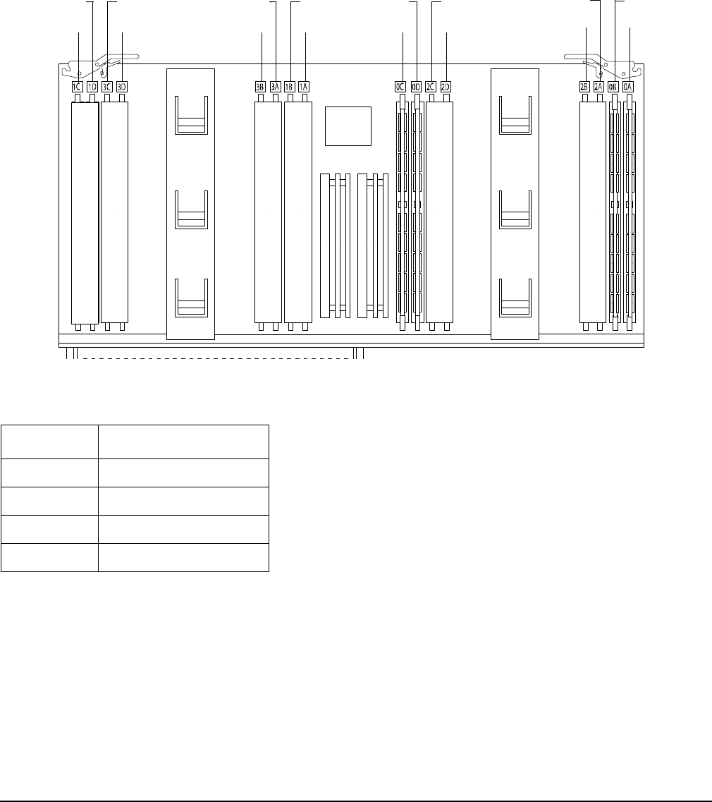
Chapter 4
Removing and Replacing Components
Removing and Replacing Server Memory DIMMs
49
16 DIMM Memory Extender Board Layout
The following details the slot locations, quads, and slot filler requirements on the 16 DIMM memory extender
board.
Figure 4-9 shows the slot locations on the 16 DIMM extender board.
Figure 4-9 16 DIMM Extender Board Slot IDs
Table 4-1 details the quads on the 16 DIMM memory extender board.
Table 4-1 Quads on the 16 DIMM Memory Extender Board
Quad Slots
Quad 0 Slots 0A, 0B, 0C, 0D
Quad 1 Slots 1A, 1B, 1C, 1D
Quad 2 Slots 2A, 2B, 2C, 2D
Quad 3 Slots 3A, 3B, 3C, 3D
0C
0D 2C
2D
2A
2B
0B
0A
3B
3A 1B
1A
1C
1D 3C
3D
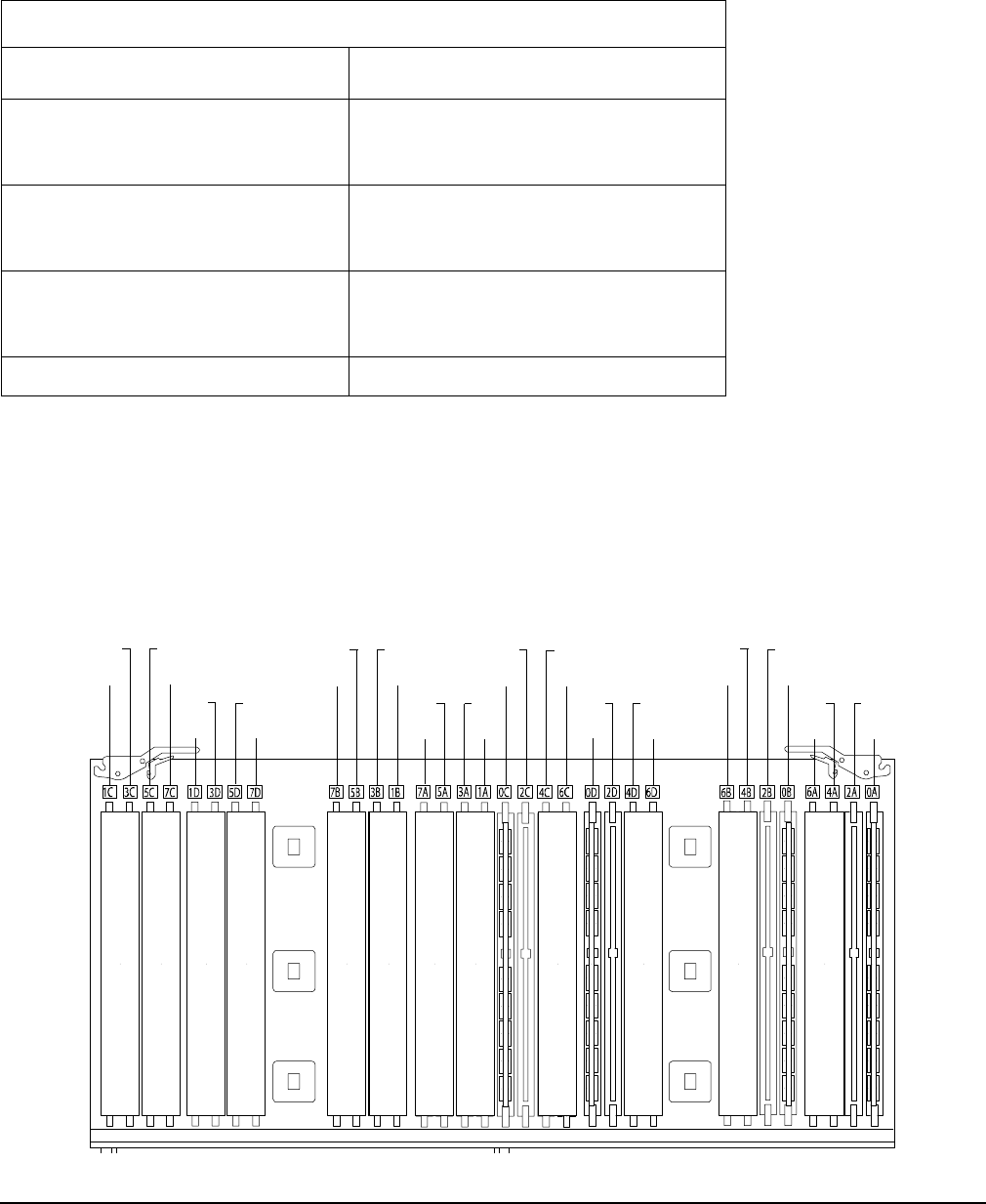
Chapter 4
Removing and Replacing Components
Removing and Replacing Server Memory DIMMs
50
Table 4-2 details the slot filler requirements when installing DIMMs on the 16 DIMM memory extender
board.
32 DIMM Memory Extender Board Layout
The following details the slot locations, quads, and slot filler requirements on the optional 32 DIMM memory
extender board.
Figure 4-10 shows the slot locations on the optional 32 DIMM extender board.
Figure 4-10 32 DIMM Extender Board Slot IDs
Table 4-2 DIMM Filler Requirements for 16 DIMM Extender Board
16 DIMM Extender Board
DIMMs Loaded Fillers Requireda
a. One DIMM filler board covers two adjacent DIMM slots.
4 DIMMs in quad 0 6 fillers total:
2 fillers in quads 1, 2, and 3
(all quads filled)
8 DIMMs in quads 0 and 1 4 fillers total:
2 fillers in quads 2 and 3
(all quads filled)
12 DIMMs in quads 0, 1, and 2 2 fillers total:
2 fillers in quads 3
(all quads filled)
16 DIMMs in quads 0, 1, 2, and 3 No fillers required
4A
6A
2A
0A
2D
0D
4D
6D
5A
7A
3A
1A
3D
1D
5D
7D
4B
6B 2B
0B
2C
0C 4C
6C
3C
1C 5C
7C
5B
7B 3B
1B
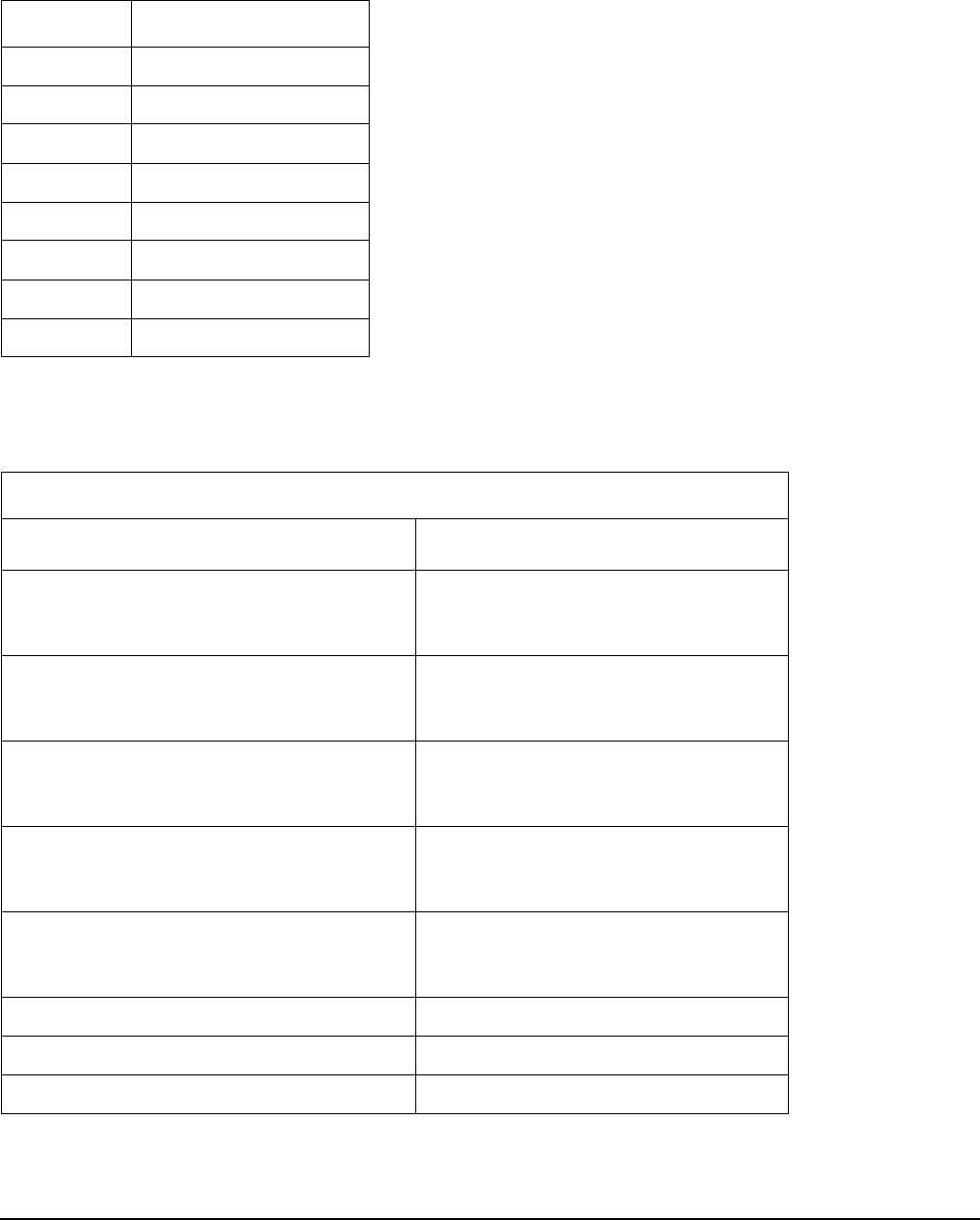
Chapter 4
Removing and Replacing Components
Removing and Replacing Server Memory DIMMs
51
Table 4-3 details the quads on the 32 DIMM memory extender board.
Table 4-4 details the slot filler requirements when installing DIMMs on the optional 23 DIMM memory
extender board.
Table 4-3 Quads on the Optional 32 DIMM Memory Extender Board
Quad Slots
Quad 0 Slots 0A, 0B, 0C, 0D
Quad 1 Slots 1A, 1B, 1C, 1D
Quad 2 Slots 2A, 2B, 2C, 2D
Quad 3 Slots 3A, 3B, 3C, 3D
Quad 4 Slots 4A, 4B, 4C, 4D
Quad 5 Slots 5A, 5B, 5C, 5D
Quad 6 Slots 6A, 6B, 6C, 6D
Quad 7 Slots 7A, 7B, 7C, 7D
Table 4-4 DIMM Filler Requirements for 32 DIMM Extender Board
32 DIMM Extender Board
DIMMs Loaded Fillers requireda
a. One DIMM filler board covers two DIMM adjacent slots.
4 DIMMs in quad 0 12 fillers total:
2 fillers in quads 1, 3, 4, 5, 6, and 7
(quad 2 remains unfilled)
8 DIMMs in quads 0 and 1 8 fillers total:
2 fillers in quads 4, 5, 6, and 7
(quads 2 and 3 remain unfilled)
12 DIMMs in quads 0, 1, and 2 8 fillers total:
2 fillers in quads 4, 5, 6, and 7
(quad 3 remains unfilled)
16 DIMMs in quads 0, 1, 2, and 3 8 fillers total:
2 fillers in quads 4, 5, 6, and 7
(all quads filled)
20 DIMMs in quads 0, 1, 2, 3, and 4 4 fillers total:
2 fillers in quads 5, 7
quad 6 remains unfilled
24 DIMMs in quads 0, 1, 2, 3, 4, and 5 No fillers required
28 DIMMs in quads 0, 1, 2, 3, 4, 5, and 6 No fillers required
32 DIMMs in quads 0, 1, 2, 3, 4, 5, 6, and 7 No fillers required

Chapter 4
Removing and Replacing Components
Removing and Replacing the Processor Extender Board
52
Removing and Replacing the Processor Extender Board
The processor extender board is located directly under the memory extender board. The processor extender
board can hold between one and four processors.
WARNING Ensure that the server is powered down and all power sources have been
disconnected from the server prior to removing or replacing the processor extender
board.
Voltages are present at various locations within the server whenever an ac power
source is connected. This voltage is present even when the main power switch is in
the off position.
Failure to observe this warning could result in personal injury or damage to
equipment.
CAUTION Failure to properly complete the steps in this procedure will result in erratic server behavior or
server failure. For assistance with this procedure contact your local HP Authorized Service
Provider.
Observe all ESD safety precautions before attempting this procedure. Failure to follow ESD
safety precautions could result in damage to the server.
Removing the Processor Extender Board
To remove the processor extender board, follow these steps:
Step 1. If rack mounted, slide the HP server out from the rack until it stops. See “Extending the Server
from the Rack” on page 39.
NOTE If desired, the processor extender board may be removed without removing the HP
server from the rack.
Step 2. Remove the front bezel. See “Removing the Front Bezel” on page 41.
Step 3. Remove the front cover. See “Removing the Front Cover” on page 42.
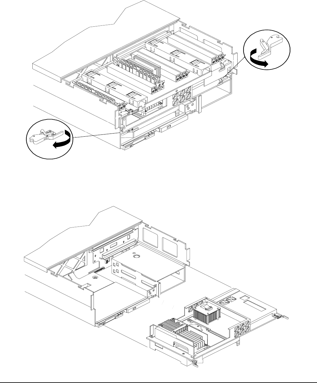
Chapter 4
Removing and Replacing Components
Removing and Replacing the Processor Extender Board
53
Step 4. Press the latch on the extraction levers located on each side of the processor extender board.
Figure 4-11 shows how to open the processor extender board latches.
Figure 4-11 Opening the Processor Extender Board Latches
Step 5. Pull out on the extraction levers to unplug the processor extender board from the socket located on
the midplane riser board. Figure 4-12 shows how to remove the extender board from the server.
Figure 4-12 Removing and Replacing the Processor Extender Board

Chapter 4
Removing and Replacing Components
Removing and Replacing the Processor Extender Board
54
Replacing the Processor Extender Board
To replace the processor extender board, follow these steps:
Step 1. Ensure the extraction levers are positioned in the outward, unlocked position.
Step 2. Align the processor extender board with the front and rear card guides.
Step 3. Slide the processor extender board down until it begins to seat in the socket located on the
midplane riser board.
Step 4. Push the extraction levers inward to the locked position in order to fully seat the processor
extender board into the socket on the midplane riser board.
Step 5. Replace the front cover. See “Replacing the Front Cover” on page 43.
Step 6. Replace the front bezel. See “Replacing the Front Bezel” on page 41.
Step 7. If rack mounted, slide the HP server into the rack until it stops. See “Inserting the Server into the
Rack” on page 39.
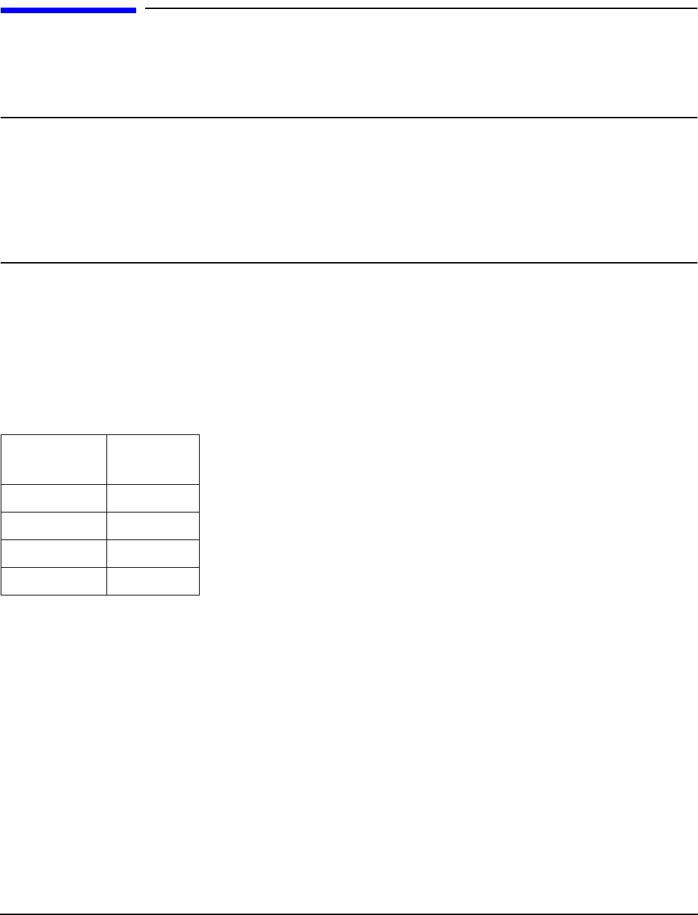
Chapter 4
Removing and Replacing Components
Removing and Replacing a Processor
55
Removing and Replacing a Processor
Us the following procedures to remove and replace a processor on the processor extender board. Processors
are located on the top and bottom surfaces of the processor extender board.
WARNING Ensure that the server is powered down and all power sources have been
disconnected from the server prior to removing or replacing a processor.
Voltages are present at various locations within the server whenever an ac power
source is connected. This voltage is present even when the main power switch is in
the off position.
Failure to observe this warning could result in personal injury or damage to
equipment.
Processor Load Order
Processor modules are housed on the processor extender board located under the top cover in the top service
bay. The processor extender board can hold between one and four processor modules. CPU 0 and CPU 1 are
located on the top of the processor extender board and CPU 2 and CPU 3 are located on the bottom.
Processors must be installed in a specific order as detailed in Table 4-5. Figure 4-13 shows the processor slot
locations on the processor extender board.
Table 4-5 Processor Load Order
Processor
Modules Socket
First CPU 0
Second CPU 1
Third CPU 2
Fourth CPU 3
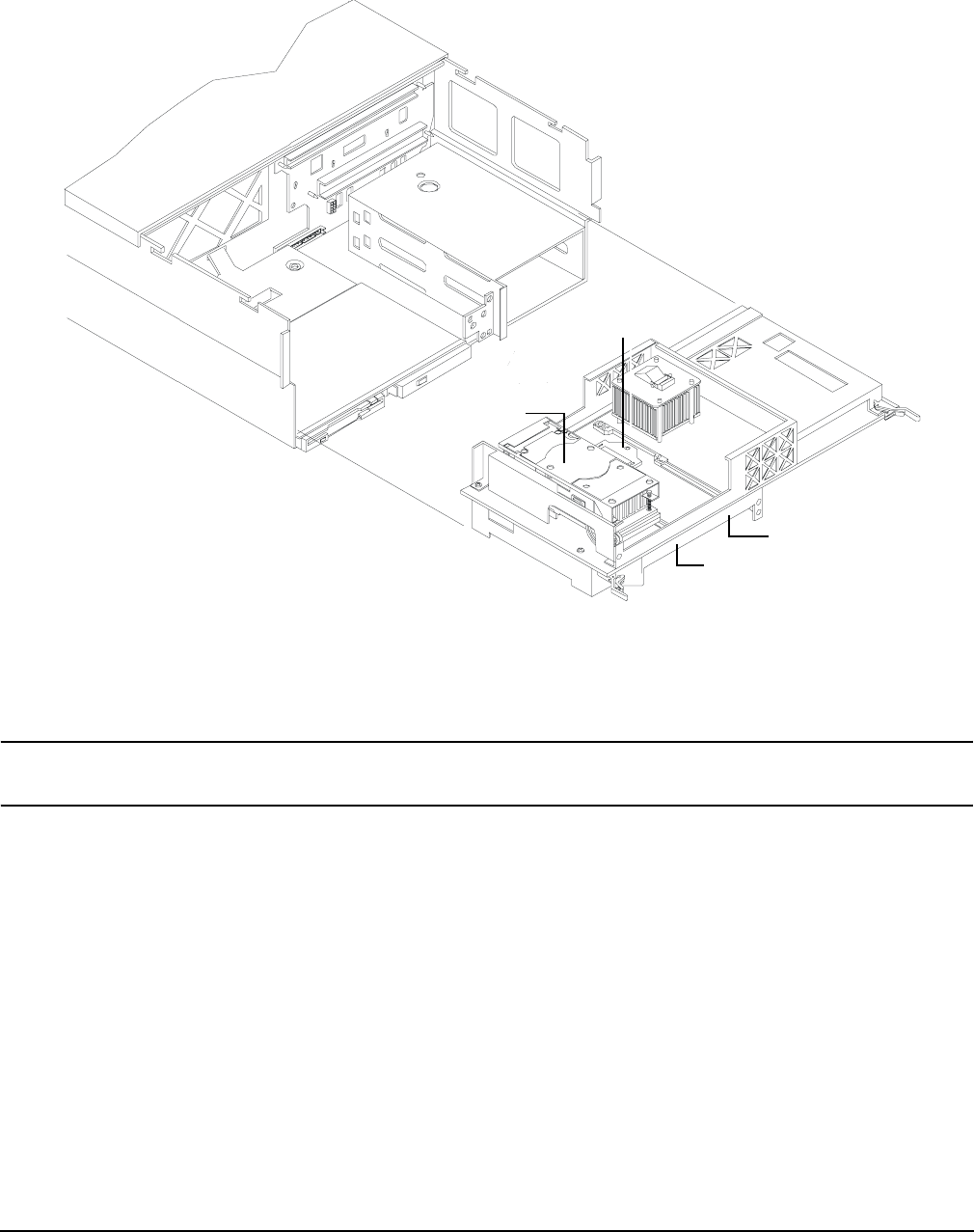
Chapter 4
Removing and Replacing Components
Removing and Replacing a Processor
56
Figure 4-13 Processor Slot Locations on the Processor Extender Board
Removing a Processor
To remove a processor on the processor extender board, follow these steps:
NOTE The processor being removed in this procedure is CPU 1. This procedure applies to all the
processors on the processor extender board.
Step 1. If rack mounted, slide the HP server out from the rack until it stops. See “Extending the Server
from the Rack” on page 39.
Step 2. Remove the front bezel. See “Removing the Front Bezel” on page 41.
Step 3. Remove the front cover. See “Removing the Front Cover” on page 42.
Step 4. Remove the processor extender board. See “Removing the Processor Extender Board” on page 52.
CPU 1
CPU 0
CPU 3 (under)
CPU 2 (under
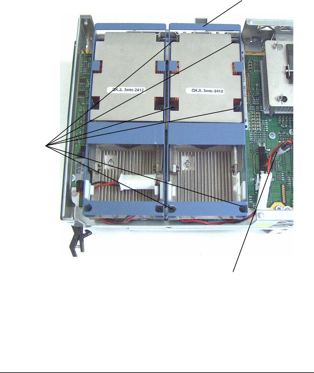
Chapter 4
Removing and Replacing Components
Removing and Replacing a Processor
57
Step 5. Using a torx T15 driver, loosen the six captive T15 shoulder screws that attach the sequencer frame
on the heatsink in the order specified in Figure 4-14 until the sequencer frame is free.
Figure 4-14 Removing the Processor Sequencer
Step 6. Remove the sequencer frame from the heatsink.
Step 7. Unplug the processor power cable from its socket on the extender board.
3
4
5
6
2
1
Sequencer
Shoulder
screws
Processor
power cable
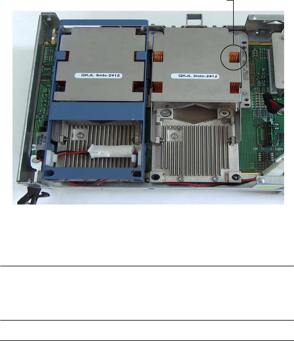
Chapter 4
Removing and Replacing Components
Removing and Replacing a Processor
58
Step 8. Unlock the processor from the processor extender board by inserting the 2 mm hex end of the
processor installation tool through the processor into the ZIF socket lock and turning it 180 degrees
counterclockwise. Figure 4-15 shows the location of the ZIF socket lock.
Figure 4-15 Unlocking the Processor from the Processor Extender Board
Step 9. Carefully remove the processor from the processor extender board, and place in an antistatic bag.
Replacing a Processor
To install a processor on the extender board, perform the following steps. If you have already removed the
processor extender board from the server, proceed to step 6.
CAUTION Ensure that the cache size is identical for all processors. Failure to observe this caution will
result in server failure.
Ensure that all processors are rated for use at the same speed. Failure to observe this caution
will result in performance degradation.
Observe all ESD safety precautions before attempting this procedure. Failure to follow ESD
safety precautions could result in damage to the server.
Processor ZIF Socket Lock
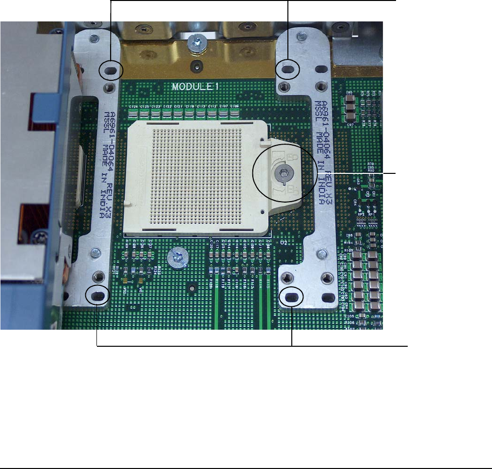
Chapter 4
Removing and Replacing Components
Removing and Replacing a Processor
59
Step 1. If rack mounted, slide the HP server out from the rack until it stops. See “Accessing a Rack
Mounted Server” on page 38.
Step 2. Remove the front bezel. See “Removing the Front Bezel” on page 41.
Step 3. Remove the front cover. See “Removing the Front Cover” on page 42.
Step 4. Remove the processor extender board. See “Removing the Processor Extender Board” on page 52.
Step 5. Using an antistatic wrist strap place the extender board on a grounding mat (Electrically
Conductive Field Service Grounding Kit-HP 9300-1155).
Step 6. Ensure the cam on the processor socket lock is in the unlocked, counterclockwise position.
Figure 4-16 shows the CPU 1 ZIF socket in the unlocked position.
Figure 4-16 CPU 1 Socket Unlocked
Step 7. Carefully lower the processor, without the sequencer clamp, onto the processor socket. Align the
pins on the bottom of the heatsink to the slots in the retention frame on the extender board.
Figure 4-16 shows the alignment holes on the processor extender board.
Processor ZIF socket
lock in unlocked
position
Alignment holes
Alignment holes
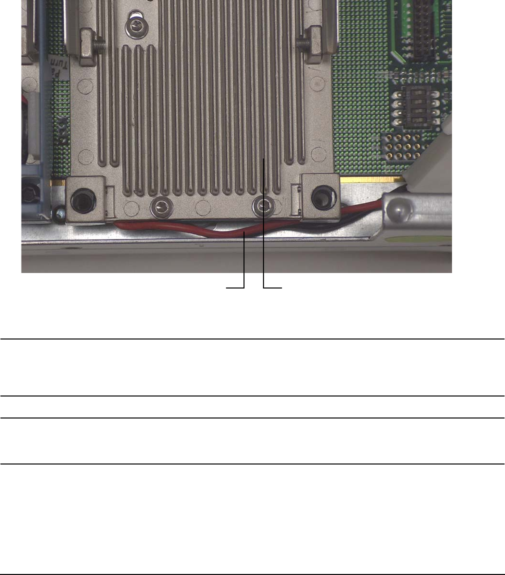
Chapter 4
Removing and Replacing Components
Removing and Replacing a Processor
60
Step 8. Make sure the processor power cable is not pinched underneath the processor before locking the
processor onto the processor extender board. Figure 4-17 shows the correct placement of the
processor power cable.
Figure 4-17 Processor Cable Routed Correctly
CAUTION Test the alignment of the assembly to the socket by gently moving the assembly back
and forth with the palm of your hand—you should feel little or no sideplay. However,
because the assembly is not yet tightened, it may tilt slightly towards the center of
the extender board—this is acceptable.
CAUTION Before locking the processor assembly into its socket, ensure that the power cable is
not pinched between the heatsink and sheet metal frame of the extender board. See
Figure 4-17 for the correct placement of the processor power cable.
Step 9. Insert the 2 mm hex end of the processor installation tool through the processor into the ZIF socket
lock. Rotate the socket 180 degrees clockwise to lock the processor to the processor extender board.
Correct routing of CPU 1 power cable CPU 1
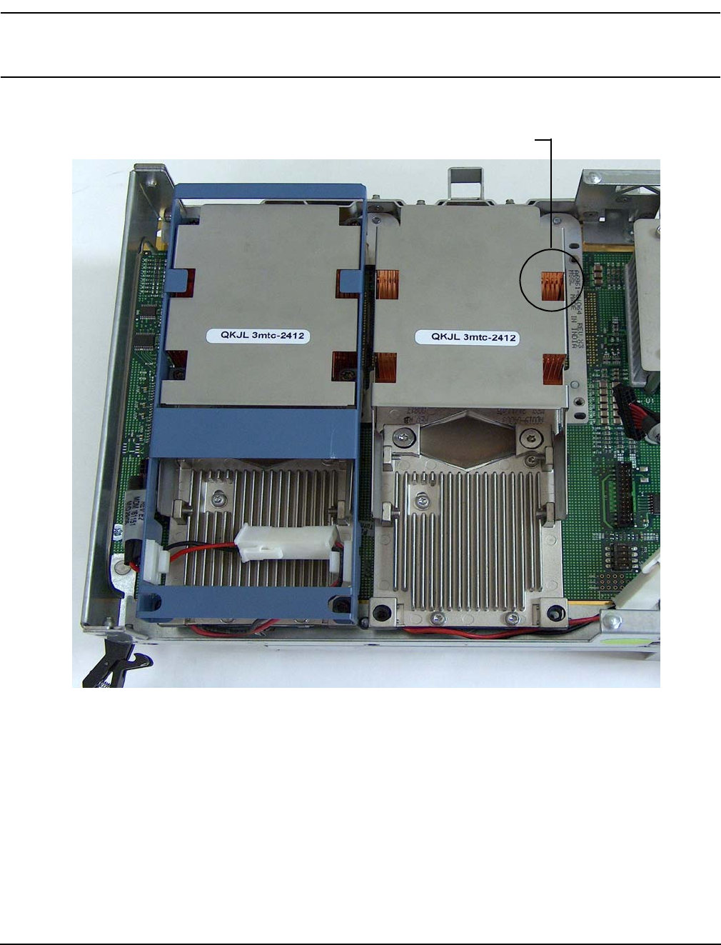
Chapter 4
Removing and Replacing Components
Removing and Replacing a Processor
61
CAUTION When rotating the locking cam, hold the palm of your hand on top of the assembly
and exert light pressure. This ensures that the assembly stays flush and level to the
socket while it is being tightened.
Figure 4-18 Locking the Processor to the Processor Extender Board
Step 10. Plug in the processor cable to its socket on the extender board.
Step 11. Place the sequencer frame over the processor.
Step 12. Using the ACX-15 torx screwdriver, tighten the six shoulder screws until they just bottom out.
Follow the tightening sequence shown in Figure 4-19.
Processor ZIF Socket Lock
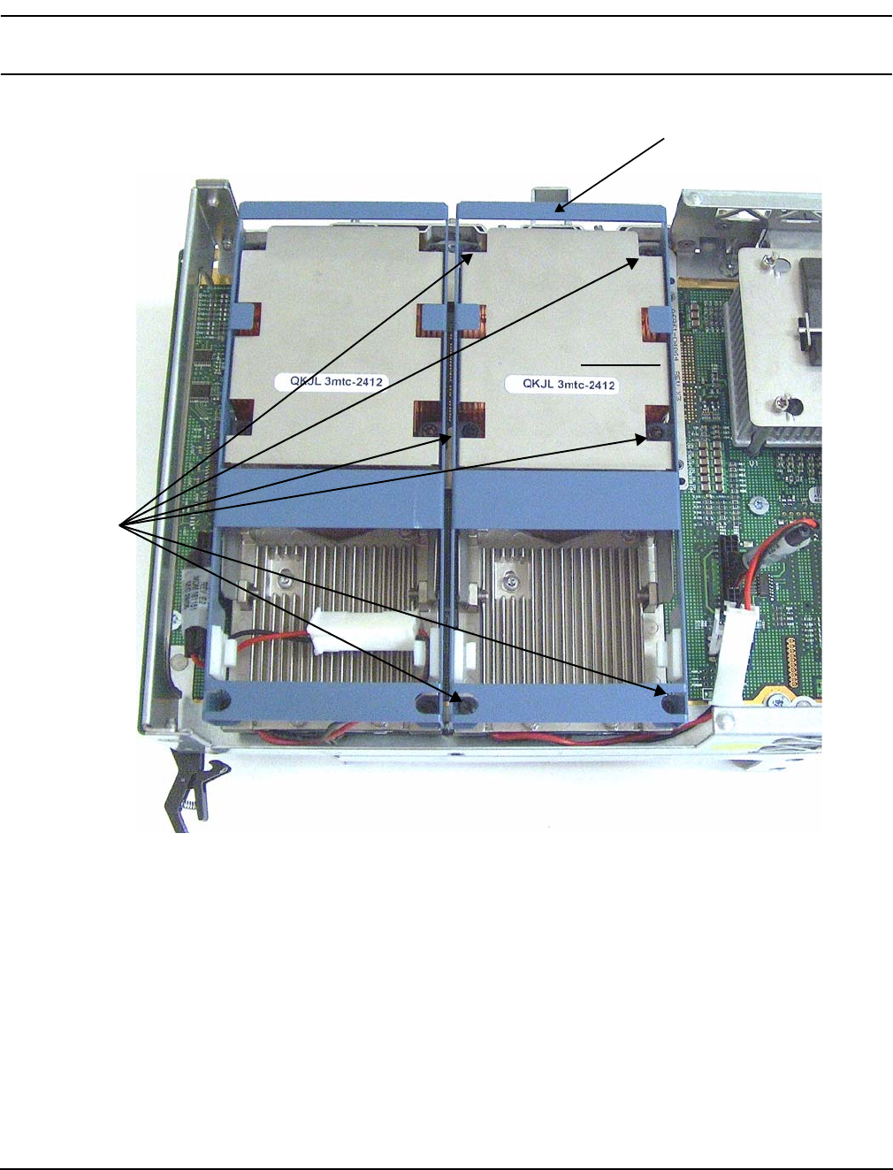
Chapter 4
Removing and Replacing Components
Removing and Replacing a Processor
62
CAUTION Do not overtighten the six shoulder screws—they may shear off if overtightened.
Stop tightening the shoulder screws when you feel them just bottom out.
Figure 4-19 Installing Sequencer on Extender Board
1
2
3
4
56
Sequencer
Shoulder
screws
Chapter 4
Removing and Replacing Components
Removing and Replacing Hot-Swap Chassis Fans
63
Removing and Replacing Hot-Swap Chassis Fans
There are three hot-swap chassis fan units in the HP server. Fan units 0, 1, and 2 are in the center of the
chassis, spanning the full chassis width. Fan units 0 and 1 are interchangeable and are in the left and center
positions. Fan unit 2 is smaller and only fits into the right-most position (behind the power supply).
CAUTION Observe all ESD safety precautions before attempting this procedure. Failure to follow ESD
safety precautions could result in damage to the server.
CAUTION When the server is running, the top cover must be replaced within two minutes to prevent
components from overheating. If the top metal cover is not replaced within five minutes, the
server automatically shuts down.
NOTE A hot-swap device does not require interaction with the operating system before the device is
removed from or installed into the server.
The ac power to the server does not have to be off to remove or replace a hot-swap chassis fan.
Removing a Hot-Swap Chassis Fan Unit
To remove a hot-swap chassis fan unit, follow these steps:
Step 1. If rack mounted, slide the HP server out from the rack until it stops. See “Extending the Server
from the Rack” on page 39.
Step 2. Remove the top cover. See “Removing the Top Cover” on page 43.
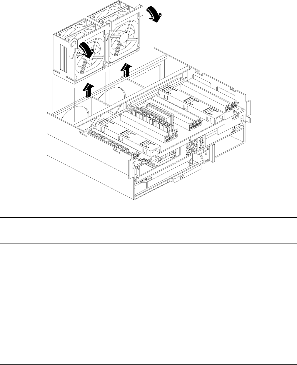
Chapter 4
Removing and Replacing Components
Removing and Replacing Hot-Swap Chassis Fans
64
Step 3. Grasp the fan unit locking handle, tilt it up, and pull out the fan from the chassis.
Figure 4-20 Removing and Replacing the Chassis Fans 0 and 1
NOTE When one fan unit is removed from the server, the remaining fan units operate at
full speed for two minutes. After two minutes the server goes into soft-shutdown
mode.
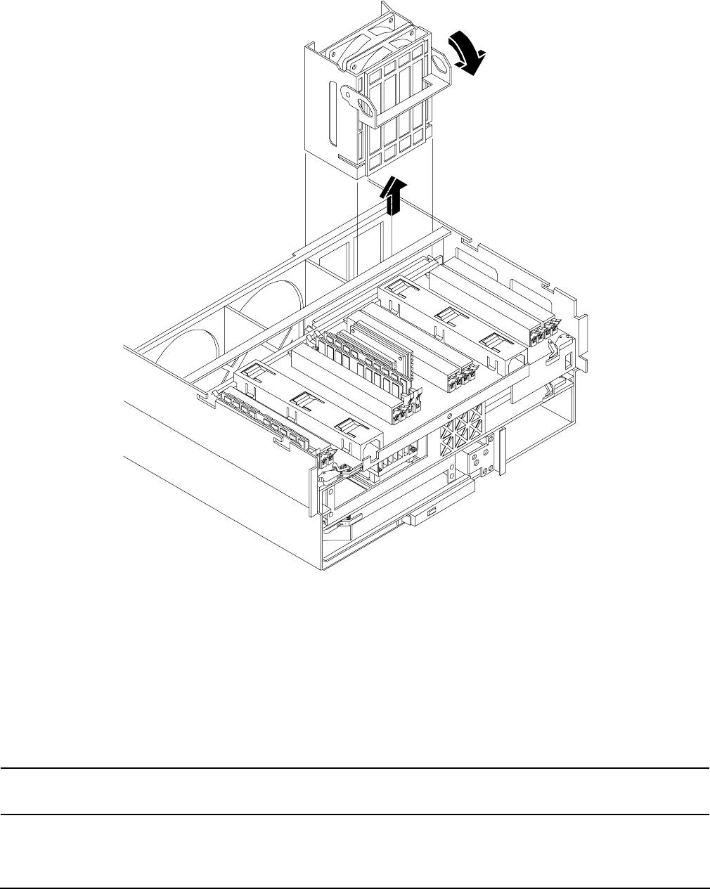
Chapter 4
Removing and Replacing Components
Removing and Replacing Hot-Swap Chassis Fans
65
Figure 4-21 Removing and Replacing the Chassis Fan 2
Replacing a Hot-Swap Chassis Fan Unit
To replace a hot-swap chassis fan unit, follow these steps:
Step 1. Orient the fan units by aligning the appropriate icon on the fan unit handle to the identical icon on
the chassis wall. Fan units 0 and 1 have “triangle” icons and fan unit 2 has a “square” icon.
Step 2. Push the fan unit firmly into the housing and close the handle until flush to the top of the
chassis—the fan unit plugs into the power outlet on the I/O baseboard.
CAUTION If the fan unit handle does not close completely, it is misaligned. Remove the fan unit
and check that the alignment icons are oriented correctly.

Chapter 4
Removing and Replacing Components
Removing and Replacing the I/O Baseboard
66
Step 3. Check the QuickFind diagnostic board LED indicating the replaced fan unit.
• When the fan is functioning normally, the LED is off.
• When the fan fails, the LED is lit.
Step 4. Replace the top cover. “Replacing the Top Cover” on page 44.
Step 5. If rack mounted, slide the HP server into the rack until it stops. “Inserting the Server into the
Rack” on page 39.
Removing and Replacing the I/O Baseboard
These procedures detail how to remove the I/O baseboard from the server. The I/O baseboard is removed from
the rear of the server.
WARNING Ensure that the server is powered down and all power sources have been
disconnected from the server prior to removing or replacing the I/O baseboard
assembly.
Voltages are present at various locations within the server whenever an ac power
source is connected. This voltage is present even when the main power switch is in
the off position.
Failure to observe this warning could result in personal injury or damage to
equipment.
CAUTION Failure to properly complete the steps in this procedure results in erratic server behavior or
server failure. For assistance with this procedure contact your local HP Authorized Service
Provider.
Observe all ESD safety precautions before attempting this procedure. Failure to follow ESD
safety precautions could result in damage to the server.
Removing the I/O Baseboard
To remove the I/O baseboard, follow these steps:
Step 1. If rack mounted, slide the HP server out from the rack until it stops. See “Extending the Server
from the Rack” on page 39.
Step 2. Remove the top cover. See “Removing the Top Cover” on page 43.
Step 3. Remove the three chassis fan units. See “Removing a Hot-Swap Chassis Fan Unit” on page 63.
Step 4. Unplug all external cabling attached to ports at the rear of the I/O baseboard.
Step 5. Unplug the SCSI cables attached to the HBA board in PCI slot 1.
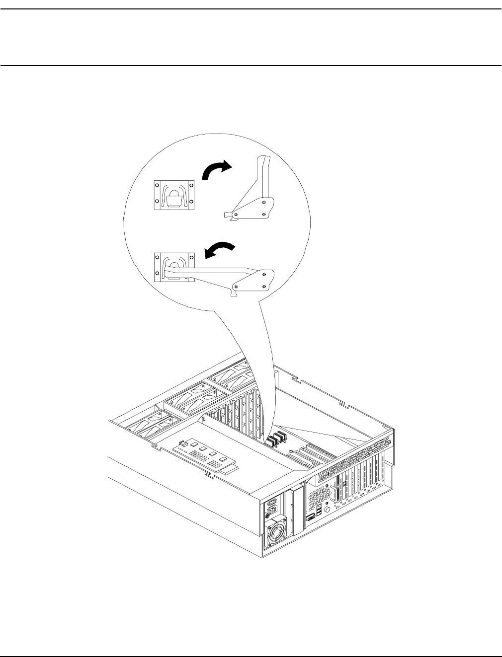
Chapter 4
Removing and Replacing Components
Removing and Replacing the I/O Baseboard
67
CAUTION When unplugging the SCSI cables, note the labeling on the SCSI A and SCSI B
channel cables. When plugging in these cables, you must match each cable with its
appropriate socket on the SCSI HBA. If the cables are mismatched your server may
not reboot. Both cables and sockets are clearly marked with the correct channel.
Step 6. Lift up on the locking lever attached to the side of the Power Supply cage to unplug the I/O
baseboard from the socket on the midplane riser board. Figure 4-22 shows the locking lever.
Figure 4-22 I/O Baseboard Locking Lever
OPEN
CLOSE
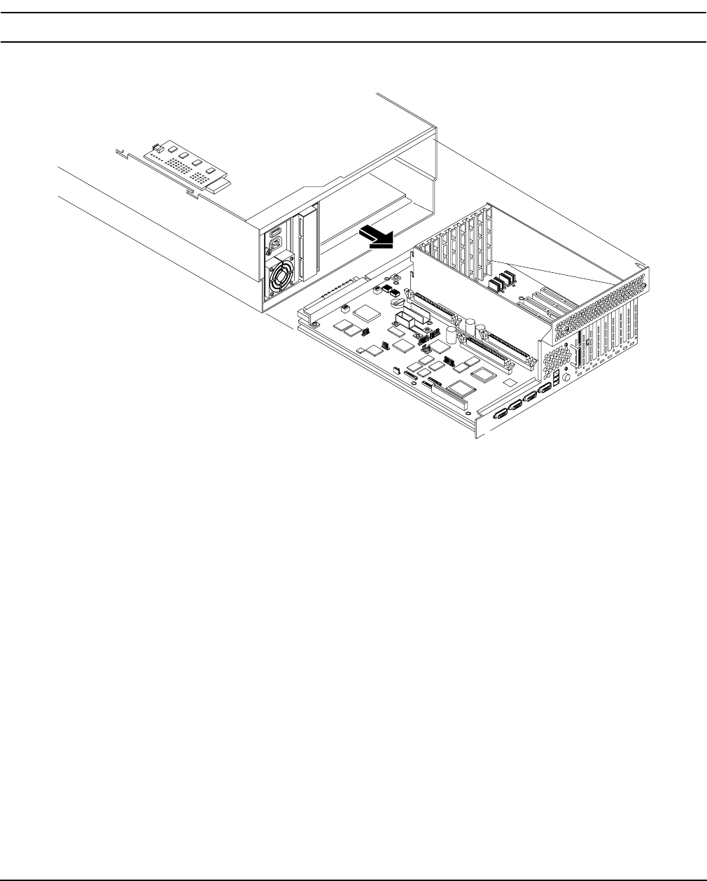
Chapter 4
Removing and Replacing Components
Removing and Replacing the I/O Baseboard
68
Step 7. Grasp the handle on the rear of the server and slide the I/O baseboard assembly all the way to the
rear until removed from chassis. Figure 4-23 shows how to remove the I/O baseboard.
NOTE The I/O baseboard assembly is large, so be careful when lifting it out of the server.
Figure 4-23 Removing the I/O Baseboard
Replacing the I/O Baseboard
To replace the I/O baseboard, follow these steps:
Step 1. Depending on the type of processor you have installed, set the I/O baseboard dip switch SW1503
(position 4) (Figure 4-24) as follows:
• Itanium 2 processor - Off
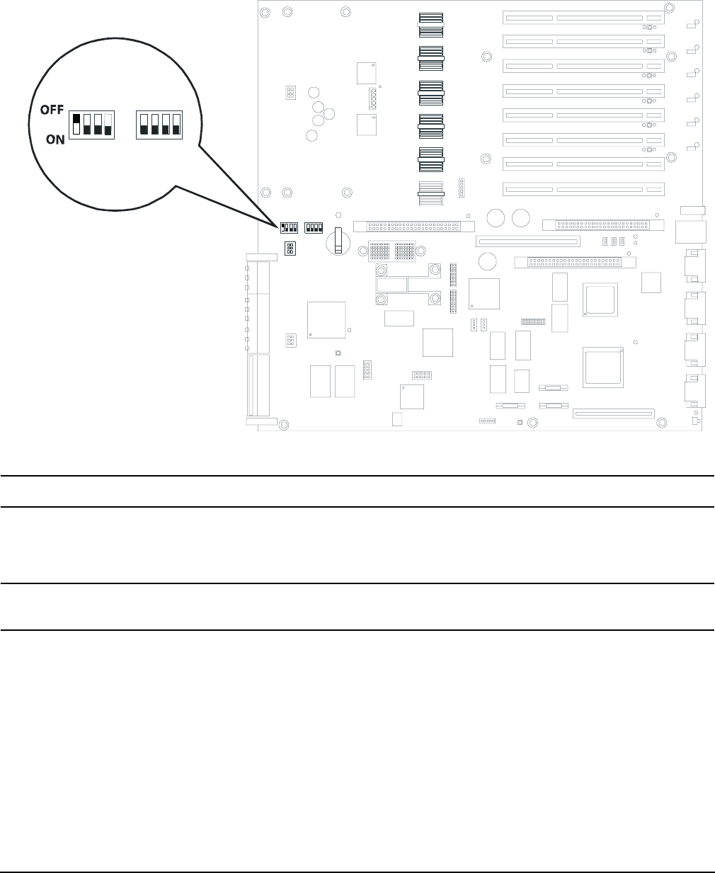
Chapter 4
Removing and Replacing Components
Removing and Replacing the I/O Baseboard
69
• MX2 dual-core processor - On
Figure 4-24 I/O Baseboard Dip Switches
NOTE The I/O baseboard is large, so use care when sliding it into the server chassis.
Step 2. Align the I/O baseboard assembly rails with the chassis slots and slide the assembly into the
chassis until it stops against the midplane riser board socket.
CAUTION Ensure the I/O baseboard locking lever is in the “up” position or the I/O baseboard
hangs up before engaging the midplane riser board socket.
Step 3. With the I/O baseboard flush against the midplane riser board socket, push down firmly on the
locking lever until the I/O baseboard plugs all the way into the midplane riser board socket.
Step 4. Replace the three chassis fan units. “Replacing a Hot-Swap Chassis Fan Unit” on page 65.
Step 5. Plug in all external cabling the rear ports of the I/O baseboard.
I/O baseboard switches

Chapter 4
Removing and Replacing Components
Removing and Replacing the I/O Baseboard
70
CAUTION When plugging the SCSI cables, note the labeling on the SCSI A and SCSI B channel
cables. You must match each cable with its appropriate socket on the SCSI HBA. If
the cables are mismatched your server may not reboot. Both cables and sockets are
clearly marked with the correct channel.
Step 6. Plug in the internal SCSI cable(s) to the HBA board in PCI slot 1.
Step 7. Replace the top cover. See “Replacing the Top Cover” on page 44
Step 8. If rack mounted, slide the HP server into the rack until it stops. See “Inserting the Server into the
Rack” on page 39.
Step 9. Power up and boot to EFI.
Step 10. Respond YES to prompts regarding copying information onto the new I/O baseboard.
Step 11. Enter SERVICE mode.
Shell> sysmode service
Current System Mode: ADMIN
You are now in SERVICE mode.
Step 12. Use the 'sysset' command to enter the product data:
Shell> sysset prodname "server rx4640"
Step 13. Use the sysset command to verify all values are set:
Shell> sysset
System Information:
Manufacturer: hp
Product Name: server rx4640
Product Number: A6961A
Secondary Product Number is Identical
Serial number: SGH43442VB
Secondary Serial Number is Identical
UUID: 3C33C58E-2E5A-11D8-A33B-4188C0AEFAE2 (Valid)
Secondary UUID is Identical
Product ID: 0x305
Step 14. Use the EFI date and time commands to set the correct local date and time.
Step 15. Boot the server and resume normal operation.

Chapter 4
Removing and Replacing Components
Removing and Replacing Hot-Plug PCI-X Cards
71
Removing and Replacing Hot-Plug PCI-X Cards
The HP Integrity rx4640 server supports PCI-X hot-plug technology and offers six PCI-X, hot-plug capable
slots.
CAUTION There are restrictions on the number of PCI-X cards that can be installed in the rx4640 server
at any given time, depending on the cards being used.
Maximum quantity for any I/O configuration using 337972-B21, AB287A, or A9890A cards:
• Three 337972-B21 cards maximum plus three unpopulated slots
• Two AB287A cards maximum plus four unpopulated slots
• Three A9890A cards maximum plus three unpopulated slots
Failure to observe this caution will result in server degradation, or server failure.
PCI-X Specifications
PCI-X technology enables the following hot-plug operations. For procedures with step-by-step instructions
describing how to add, replace, delete, and locate PCI-X cards see “Hot-Plug Operation Procedures” on
page 77.
•Online Addition (OL-A)
You can install new PCI-X expansion cards in previously empty slots without powering down the server.
•Online Replacement (OL-R)
You can replace a previously occupied slot with a new PCI-X expansion card by suspending the driver.
This operation combines removing an active card and replacing it with an equivalent capability card. The
existing driver for the old card must be compatible with the new card.
CAUTION A special OL-R requirement for HP-UX 11i v2 is that the card to be inserted (replaced)
must be exactly the same as the removed card. This is also known as like-for-like
replacement.
NOTE Windows Server 2003 Enterprise Edition does not support OL-R. Instead, you can do a
combination of an OL-D operation followed by an OL-A operation. This is the equivalent of
an OL-R operation.
•Online Deletion (OL-D)
You can remove an existing PCI-X expansion card. This operation is different from OL-R because there
are no restrictions placed on the type of replacement card that you can use. In this operation, the drivers
are also completely removed from the slot.
NOTE HP-UX 11i v2 does not support OL-D. It does support OL-R.
•PCI-X Slot Locate (Locate)

Chapter 4
Removing and Replacing Components
Removing and Replacing Hot-Plug PCI-X Cards
72
To easily locate the PCI-X slot at which you wish to perform a hot-plug operation, you can command the
attention LEDs, on the OLX divider and the I/O baseboard, to blink and act as visual cues to the active slot
location. This operation is always initiated through a software or web interface and is optional to the
operating system on your HP server.
Operating System Support for Hot-Plug PCI-X Operations
The capability of each operating system to support hot-plug PCI-X operations is different. The following
explanation details the capabilities of each operating system.
NOTE Open VMS does not support hot-plug PCI-X operations.
•HP-UX 11i v2
HP-UX 11i v2 supports only OL-A, OL-R, and Locate hot-plug PCI-X operations.
In OL-R, it is a requirement that the card to be inserted (replaced) be exactly the same as the card being
removed. During this OL-R operation, HP-UX 11i v2 suspends the device driver and re-enables it upon
completion of the OL-R operation.
In HP-UX 11i v2, the Locate function is only available through the command line or web interface.
•Windows Server 2003 Enterprise Edition
Windows Server 2003 Enterprise Edition supports only OL-A and OL-D hot-plug PCI-X operations.
In OL-D, Windows Server 2003 Enterprise Edition will delete the device object, after the card’s successful
removal from the slot. You do not have to re-install drivers for the deleted device on subsequent insertions
or reboots
To perform a card replacement hot-plug PCI-X operation in Windows Server 2003, you must first perform
an OL-D operation followed by an OL-A operation.
•Linux Red Hat Advanced Server 2.1
At this time Linux RHEL4 U3 does not support hot-plug PCI-X technology.
Table 4-6 shows hot-plug operations that are available in HP-UX 11i v2, Windows Server 2003 Enterprise
Edition, and Linux Red Hat Advanced Server 2.1 operating systems.
Table 4-6 Hot-Plug Operation and OS Compatibility
Hot-Plug
Operation HP-UX 11i v2 Windows Server 2003
Enterprise Edition
Linux Red Hat
Enterprise
Advanced Server
4 Update 3
OL-A Yes Yes No
OL-R Yes. HP-UX 11i v2 demands
like-for-like replacement. A like-for-like
card means that the new card is exactly
the same as the card being replaced.
No. But, you can perform a
combination of OL-D and
OL-A to replace a card.
No
OL-D Not supported by HP-UX 11i v2. Yes No

Chapter 4
Removing and Replacing Components
Removing and Replacing Hot-Plug PCI-X Cards
73
PCI-X Hardware and Software Interfaces
Table 4-7 shows what hot-plug hardware and software interfaces are available on HP-UX 11i v2, Windows
Server 2003 Enterprise Edition, and Linux Red Hat Advanced Server 2.1 operating systems.
Locate Yes. Only supported through the
command line interface or the web
interface.
No No
Table 4-7 Hot-Plug Hardware and Software Interfaces and OS Availability
Hot-Plug PCI-X Interface HP-UX 11i v2
Windows Server
2003 Enterprise
Edition
Linux Red Hat
Enterprise
Advanced Server
4 Update 3
Hardware interface comprised of:
—Attention Button
—Manual Retention Latch
—Power LED
—Attention LED
—PCI-X card lock
Yes Yes No
Graphical User Interface Yes Yes. You can use the
Safely Remove
Hardware icon in
the tool tray or
device manager to
remove a device
(OL-D).
OL-A is only
possible through the
hardware interface.
No
Command Line Interface (CLI) Yes -olrad command.
Read Interface Card OL*
Support for HP-UX Servers
and Workstations, olrad
Command Line Interface
at http://docs.hp.com.
No No
Table 4-6 Hot-Plug Operation and OS Compatibility (Continued)
Hot-Plug
Operation HP-UX 11i v2 Windows Server 2003
Enterprise Edition
Linux Red Hat
Enterprise
Advanced Server
4 Update 3

Chapter 4
Removing and Replacing Components
Removing and Replacing Hot-Plug PCI-X Cards
74
PCI-X Slot Locations and Configurations
PCI-X slots are numbered from 1 through 8 in your HP server. Figure 4-25 shows the slot locations on the I/O
baseboard.
The following describes configuration requirements for slots 1 through 8 (see Table 4-8 for configuration
requirements):
• PCI slots 1 and 2 are dedicated for use by the core I/O cards—SCSI HBA card in slot 1 and Gigabit
Ethernet LAN card in slot 2. Slots 1 and 2 are not hot-plug capable. Additional PCI-X expansion cards
may not be placed in slots 1 or 2.
• Slots 3 and 4 share a PCI-X bus, and slots 5 and 6 share a PCI-X bus. The maximum capability of each
slot sharing a PCI-X bus is PCI-X 66 MHz. If a PCI-X 133 MHz card is placed in a slot sharing a bus, the
maximum capability the PCI-X 133 MHz card can run at is PCI-X 66 MHz. If different modes (PCI vs.
PCI-X) or slower speeds (33 MHz) are used, then the slot automatically downgrades to accept the change.
Shared slots have card compatibility restrictions. If one of the shared slots is occupied then the card being
added to the second slot is limited by the configuration of the occupied slot. If the new card has a slower
capability than the current bus configuration, it will be rejected. If the new card has a faster capability
than the current bus configuration, it will only run at the bus mode and frequency of the current bus
configuration (slower).
1. If you have a 66 MHz card in slot 3, and you hot-plug insert a 33 Mhz card into slot 4, then the
operation will not succeed. The new 33 MHz card will not initialize and the slot will power down
because you cannot change bus speed during hot-plug operations.
NOTE If the server is rebooted in the new configuration, then both cards re-initialize to run at
33 MHz. This is because the server firmware can only change the bus capability from
66 MHz down to 33 MHz.
2. If you have a 33 MHz card in slot 3, and you hot-plug insert a 66 Mhz card into slot 4, it will work but
the new card will run at 33 MHz. This also applies to slots 5 and 6, as they are shared (both use a
common bus).
3. If your unit is powered down and you insert a 33 MHz card into slot 4 (that shares a 66 MHz card in
slot 3), then both cards will run at 33 MHz when the unit is powered up. This also applies to slots 5
and 6, as they are shared (both use a common bus).
Web Interface Yes- pdweb command.
Read Interface Card OL*
Support for HP-UX Servers
and Workstations,
pdweb-Peripheral Device
tool Web Interface, at
http://docs.hp.com.
No No
Table 4-7 Hot-Plug Hardware and Software Interfaces and OS Availability
Hot-Plug PCI-X Interface HP-UX 11i v2
Windows Server
2003 Enterprise
Edition
Linux Red Hat
Enterprise
Advanced Server
4 Update 3

Chapter 4
Removing and Replacing Components
Removing and Replacing Hot-Plug PCI-X Cards
75
• Slots 7 and 8 are single slots, they do not share a PCI-X bus. The maximum capability of each slot is
PCI-X 133 MHz. Only slots 7 and 8 allow 133 Mhz, PCI-X cards to run at full speed. These two slots are
not limited by bus mode frequency related incompatibilities.
CAUTION If you are using Linux Red Hat Enterprise Advanced Server 4 Update 3 operating system and
you want to install a 1000b-Sx GigE card, do not install it into a slot that shares a bus with a 33
MHz card. In this configuration the Linux driver will not initialize the new card.
Table 4-8 PCI-X Card vs. Slot Frequency/Bus Mode Compatibility for Shared
Slotsa
a. The conditions described in this table apply only to shared slots (slots 3,4-bus
2 and 5,6-bus 3). Slots 7 and 8 are not shared slots.
Current PCI Bus
Mode and
Frequency for
the Shared Slot
Cards to be installed
PCI 33 PCI 66 PCI-X 66 PCI-X 133
PCI 33 MHz Compatibleb
b. Compatible: card is accepted and runs at frequency shown.
Compatible
(note b)
New card
running at
PCI 33
Compatible
(note b)
New card
running at
PCI 33
Compatible
(note b)
New card
running at
PCI 33
PCI 66 MHz Incompatible
-Frequencyc
c. Incompatible-Frequency: card is rejected. The new card will not initialized and
will power down due to frequency mismatch.
Compatible
(note b)
Compatible
(note b)
New card
running at
PCI 66
Compatible
(note b)
New card
running at
PCI 66
PCI-X 66 MHz Incompatible
-Frequency
(note c)
Incompatible-
Busd
d. Incompatible-Bus: Card is rejected. The new card will not initialize and will
power down due to bus mode mismatch.
Compatible
(note b)
Compatible
(note b)
New card
running at
PCI-X 66
PCI-X 133 MHze
e. Maximum bus mode and frequency supported on shared slots is PCI-X 66
MHz.
Incompatible
-Frequency
(note c)
Incompatible-
Frequency
(note c)
Compatible
(note b)
New card
Compatible
(note b)
New card
running at
PCI-X 66
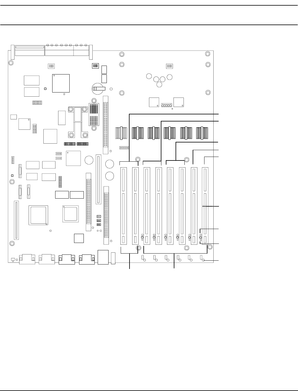
Chapter 4
Removing and Replacing Components
Removing and Replacing Hot-Plug PCI-X Cards
76
CAUTION Do not use more than 3 RAID cards in any of the slots on your HP Integrity rx4640 server.
Server power limitations restrict the use of more than 3 RAID cards per server.
Figure 4-25 Slot ID Numbering
PCI-X Bus 1
PCI-X Bus 2
PCI-X Bus 3
PCI-X Bus 4
PCI-X Bus 5
Slot ID Number
Amber attention LEDs, 6x
Green power LEDs, 6x
Amber attention LEDs, 6x
1 23456 78
Core I/O
PCI-X
Public I/O
PCI-X, Hot-Plug

Chapter 4
Removing and Replacing Components
Removing and Replacing Hot-Plug PCI-X Cards
77
Hot-Plug Operation Procedures
The hot-plug procedures described in this section will use the hardware interface only. Software interface
procedures are described in Table 4-7, “Hot-Plug Hardware and Software Interfaces and OS Availability.” For
a complete understanding of all HP-UX 11i v2 hot-plug techniques and concepts, it is recommended that you
see the Interface Card OL* Support for HP-UX Servers and Workstations on the HP website at:
http://docs.hp.com.
CAUTION Before adding or replacing a PCI-X card, determine if that card is critical to your servers
operation. If you replace a card that is still operating and it is a critical resource to your server,
you may cause undesired server downtime. Read Interface Card OL* Support for HP-UX
Servers and Workstations, Critical Resources at http://docs.hp.com, prior to performing a
hot-plug operation.
Online Addition-(OL-A)
Before installing a PCI-X card, ensure that the proper drivers for that PCI-X card are installed.
To add a PCI-X card into an empty slot, follow these steps:
Step 1. If rack mounted, slide the HP server out from the rack until it stops. See “Extending the Server
from the Rack” on page 39.
Step 2. Remove the top cover from the chassis. See “Removing the Top Cover” on page 43.
Step 3. If the power LED is steady-on (power to slot is on), go to step 4. If the power LED is steady-off
(power to slot is off), go to step 5.
Step 4. To turn off power to the slot, pull up on the manual retention latch (MRL) located on the OLX
divider. The power LED goes to steady-off. Figure 4-26 shows the layout of the card divider.
CAUTION Do not pull up on the MRL of a powered-on, occupied slot or your server will crash.
This OL-A procedure is for powering down a powered-on, unoccupied slot only. For a
detailed procedure on how to power down an occupied slot see “Online
Replacement-(OL-R)” or “Online Deletion (OL-D)”.
Step 5. Ensure that the MRL is already open and insert the PCI-X card to be added into the powered down
slot. Figure 4-27 shows how to correctly install a PCI-X card.
CAUTION When inserting the PCI-X card, be careful you do not accidentally touch an attention
button on the other OLX dividers—this will initiate an undesired shutdown of
another PCI-X card/slot.
Also, ensure that you fully seat the card into the slot or undesired results may occur
after power is re-applied to the slot.
Step 6. Push the manual retention latch down until it seats against the chassis wall.
Step 7. Turn the PCI-X card lock to the closed position to capture the PCI-X card and manual retention
latch into the closed position.
Step 8. Press the attention button and the power LED starts to blink. Wait until the power LED goes from
blinking to steady-on.
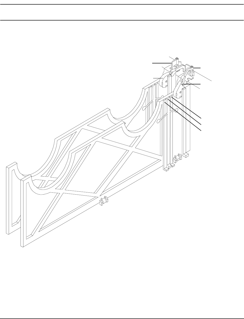
Chapter 4
Removing and Replacing Components
Removing and Replacing Hot-Plug PCI-X Cards
78
NOTE After pushing the attention button, you have 5 seconds to cancel the operation by
pushing the attention button again.
Step 9. Replace the top cover.
Step 10. Push the HP server all the way back into the rack until it stops.
Figure 4-26 PCI-X OLX Divider Layout
PCI-X card latch
closed position
Manual retention
latch—closed
PCI-X card latch
open position
Manual retention
latch—open
Power LED
light pipe
Attention button
Attention LED
light pipe
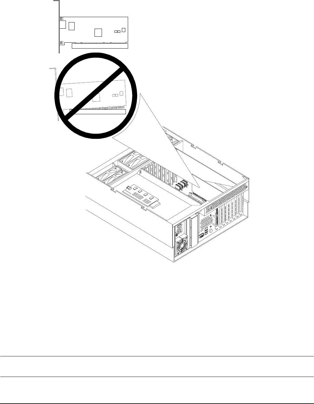
Chapter 4
Removing and Replacing Components
Removing and Replacing Hot-Plug PCI-X Cards
79
Figure 4-27 Inserting PCI-X Card
Online Deletion (OL-D)
To delete a PCI-X card from an occupied slot, follow these steps:
Step 1. If rack mounted, slide the HP server out from the rack until it stops. See “Extending the Server
from the Rack” on page 39.
Step 2. Remove the top cover from the chassis. See “Removing the Top Cover” on page 43.
Step 3. Press the attention button located on the OLX divider that controls the affected slot—the power
LED starts to blink. Wait until the power LED goes from blinking to steady-off.
NOTE After pushing the attention button, you have 5 seconds to cancel the operation by
pushing the attention button again.

Chapter 4
Removing and Replacing Components
Removing and Replacing Hot-Plug PCI-X Cards
80
Step 4. Turn the PCI-X card lock on the chassis until the manual retention latch (MRL) is free to pull up.
Step 5. At this point, the power to the slot is off; pull up on the manual retention latch located on the OLX
divider. Figure 4-26 shows the layout of the PCI-X card divider.
Step 6. Remove the existing PCI-X card from the slot.
Step 7. Push the manual retention latch down until it seats against the chassis wall.
Step 8. Replace the top cover. See“Replacing the Top Cover” on page 44.
Step 9. Push the HP server all the way back into the rack until it stops. See “Inserting the Server into the
Rack” on page 39.
Online Replacement-(OL-R)
As discussed earlier, OL-R is a combination of an OL-D procedure followed by an OL-A procedure.
CAUTION For HP-UX 11i v2 only. You can only replace an existing card with a like card.
To remove and replace a PCI-X card into a populated slot, follow these steps:
Step 1. If rack mounted, slide the HP server out from the rack until it stops. See “Extending the Server
from the Rack” on page 39.
Step 2. Remove the top cover from the chassis. See “Removing the Top Cover” on page 43.
Step 3. Press the attention button located on the OLX divider controls the affected slot—the power LED
starts to blink. Wait until the power LED goes from blinking to steady-off.
NOTE After pushing the attention button, you have 5 seconds to cancel the operation by
pushing the attention button again.
Step 4. Turn the PCI-X card lock on the chassis until the manual retention latch (MRL) is free to pull up.
Step 5. At this point, the power to the slot is off; pull up on the manual retention latch located on the OLX
divider. Figure 4-26 shows the layout of the PCI-X card divider.
Step 6. Remove the existing PCI-X card from the slot.
Step 7. Insert the new PCI-X card into the powered down slot. Figure 4-27 shows how to correctly install a
PCI-X card.
CAUTION When inserting the PCI-X card, be careful you do not accidentally touch an attention
button on the other OLX dividers—this will initiate an undesired shutdown of
another PCI-X card/slot. If you accidentally press the wrong attention button, you
have five seconds to push the attention button again to cancel the action.
Also, ensure that you fully seat the card into the slot or undesired results may occur
after power is re-applied to the slot.
Step 8. Push the manual retention latch down until it seats against the chassis wall.

Chapter 4
Removing and Replacing Components
Removing and Replacing OLX Dividers
81
Step 9. Turn the PCI-X card lock on the chassis to the closed position. This locks the PCI-X card into its slot
and the manual retention latch into the closed position.
Step 10. Press the attention button—the power LED starts to blink.
Step 11. Wait for the power LED to stop blinking—the PCI-X card is now active.
Step 12. Replace the top cover. “Replacing the Top Cover” on page 44.
Step 13. Push the HP server all the way back into the rack until it stops. See “Inserting the Server into the
Rack” on page 39.
Removing and Replacing OLX Dividers
OLX dividers are located on the I/O baseboard, between the PCI cards. Six OLX dividers provide short circuit
protection to the hot-plug PCI accessory boards by preventing inadvertent contact between boards during the
replacement or addition of a board.
Additionally, each OLX divider has two light pipes that transfer illumination from one green power LED and
one amber attention LED, mounted on the I/O board, to the top of the divider. The light pipes allow the LED
status to be easily viewed when the top cover is removed.
WARNING Ensure that the server is powered down and all power sources have been
disconnected from the server prior to removing or replacing a PCI card divider.
Voltages are present at various locations within the server whenever an ac power
source is connected. This voltage is present even when the main power switch is in
the off position.
Failure to observe this warning could result in personal injury or damage to
equipment.
CAUTION Observe all ESD safety precautions before attempting this procedure. Failure to follow ESD
safety precautions could result in damage to the server.
Removing an OLX Divider
To remove an OLX divider, follow these steps:
NOTE An alternative method of removing OLX dividers individually is to remove all OLX dividers at
once by removing the rack they are mounted in from the I/O baseboard, then removing or
replacing the individual OLX divider, and then replacing the rack back on the I/O baseboard.
The OLX divider rack is attached to the I/O baseboard with 4 torx T15 fasteners.
Step 1. If rack mounted, slide the HP server out from the rack until it stops. See “Extending the Server
from the Rack” on page 39.
Step 2. Remove the front bezel. See “Removing the Front Bezel” on page 41.
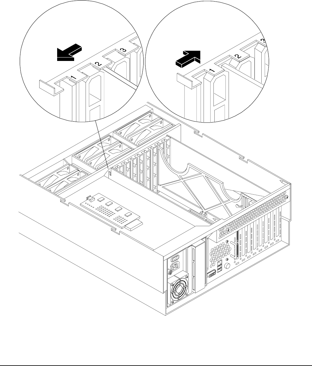
Chapter 4
Removing and Replacing Components
Removing and Replacing OLX Dividers
82
Step 3. Remove the top cover. See “Removing the Top Cover” on page 43.
Step 4. Slide open the latch on the rear PCI cage wall to unlock the rear edge of the PCI divider.
Figure 4-28 shows how to open the OLX divider latch.
Figure 4-28 Opening and Closing the OLX Divider Latch
CLOSED OPEN
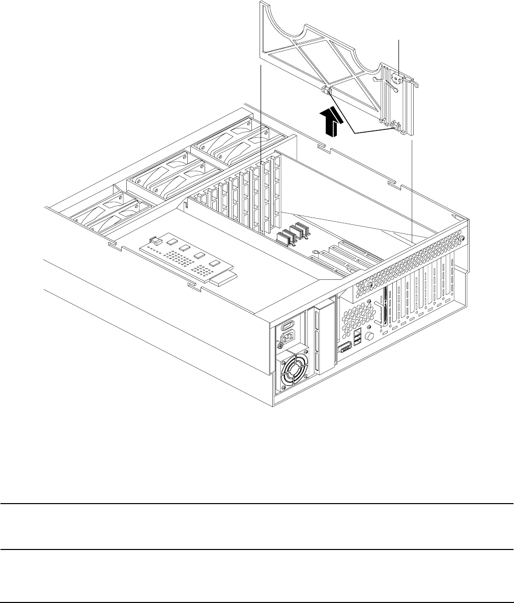
Chapter 4
Removing and Replacing Components
Removing and Replacing OLX Dividers
83
Step 5. Pull up on the manual retention latch to unlock it from the chassis wall. Figure 4-29 shows where
the manual retention latch is on the OLX divider.
Figure 4-29 Removing and Replacing the OLX Divider
Step 6. If you are removing the entire OLX divider rack, remove the four T15 fasteners holding the rack to
the I/O baseboard.
Step 7. Using your fingers, push the two tabs that attach the OLX divider to the I/O baseboard and pull the
OLX divider up sharply to disengage it from the I/O baseboard.
CAUTION When extracting the OLX divider, ensure that you release the locking tabs
completely or you may damage them. If you damage the tabs, the OLX divider may
not seat properly when you reinsert it.
Manual retention latch
Locking tabs

Chapter 4
Removing and Replacing Components
Removing and Replacing OLX Dividers
84
Replacing an OLX Divider
To replace an OLX divider, follow these steps:
Step 1. Insert the OLX divider into the available slots on the I/O baseboard and push down firmly to seat it
into the slots.
Step 2. At this point, if you are replacing the entire OLX divider rack on to the I/O baseboard, replace the
four torx T15 fasteners.
Step 3. Slide the latch on the rear OLX divider wall closed, to lock the rear edge of the PCI divider.
Figure 4-28 shows how to close the OLX divider latch.
Step 4. Push down on the manual retention latch until it locks into the chassis wall.
Step 5. Replace the top cover. See “Replacing the Top Cover” on page 44.
Step 6. Replace the front bezel. See “Replacing the Front Bezel” on page 41.
Step 7. If rack mounted, slide the HP server into the rack until it stops. See “Inserting the Server into the
Rack” on page 39.
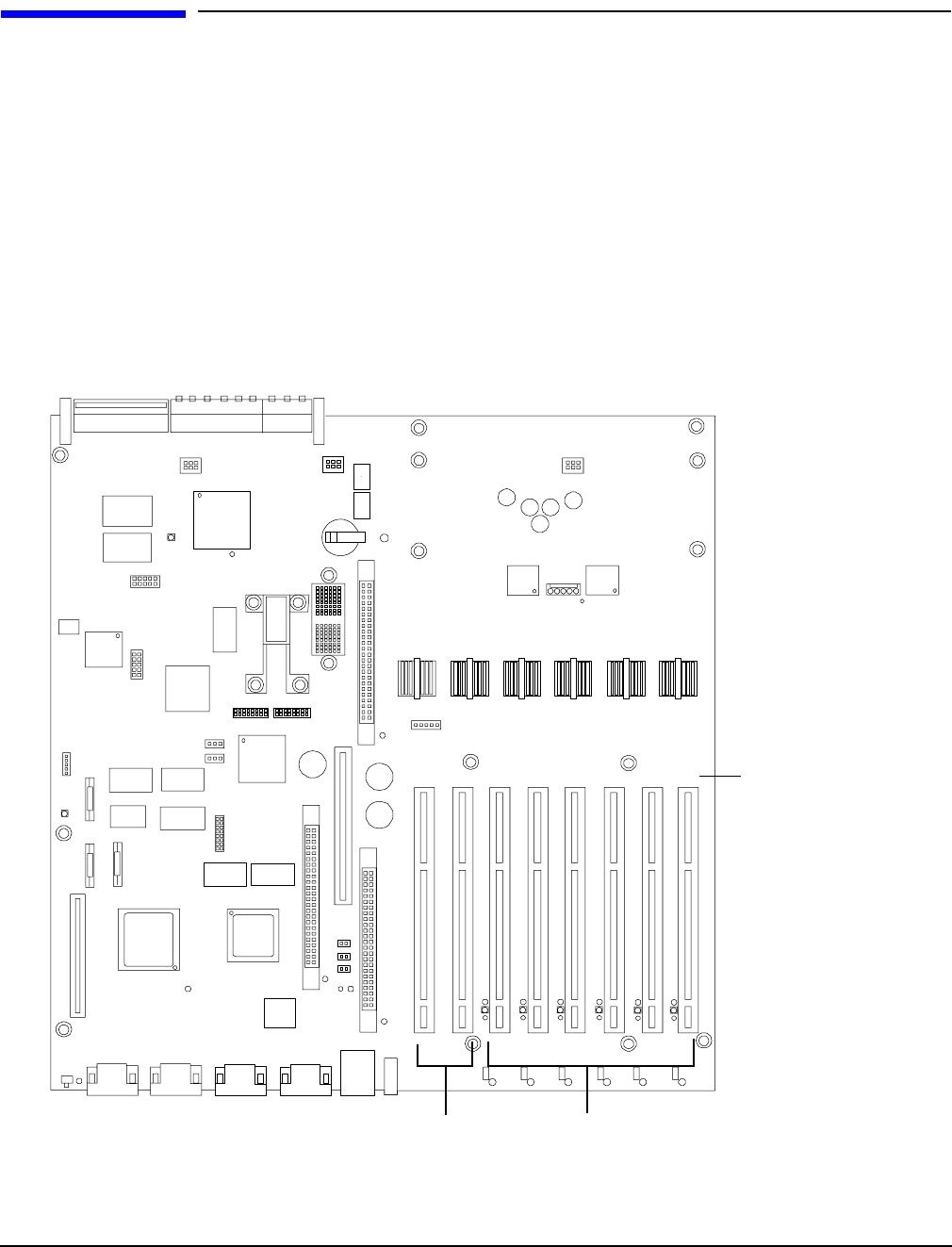
Chapter 4
Removing and Replacing Components
Removing and Replacing Core I/O Cards
85
Removing and Replacing Core I/O Cards
The HP Integrity rx4640 server has two I/O card slots that are dedicated for core I/O cards. They are labelled
slots 1 and 2 on the I/O baseboard. Figure 4-30 shows the location of the core I/O slots on the I/O baseboard.
PCI Slot Locations and Configurations
The following describes configuration requirements for slots 1 and 2:
• PCI slot 1 is dedicated for use by a SCSI HBA card. Slot 1 is not hot-plug capable. Additional PCI
expansion cards may not be placed in slot 1.
• PCI slot 2 is dedicated for use by a LAN card. Slot 2 is not hot-plug capable. Additional PCI expansion
cards may not be placed in slot 2.
Figure 4-30 Slot ID Numbering
Slot ID Number
1 2 345 678
Core I/O
PCI slots Public I/O PCI slots
Back of Server
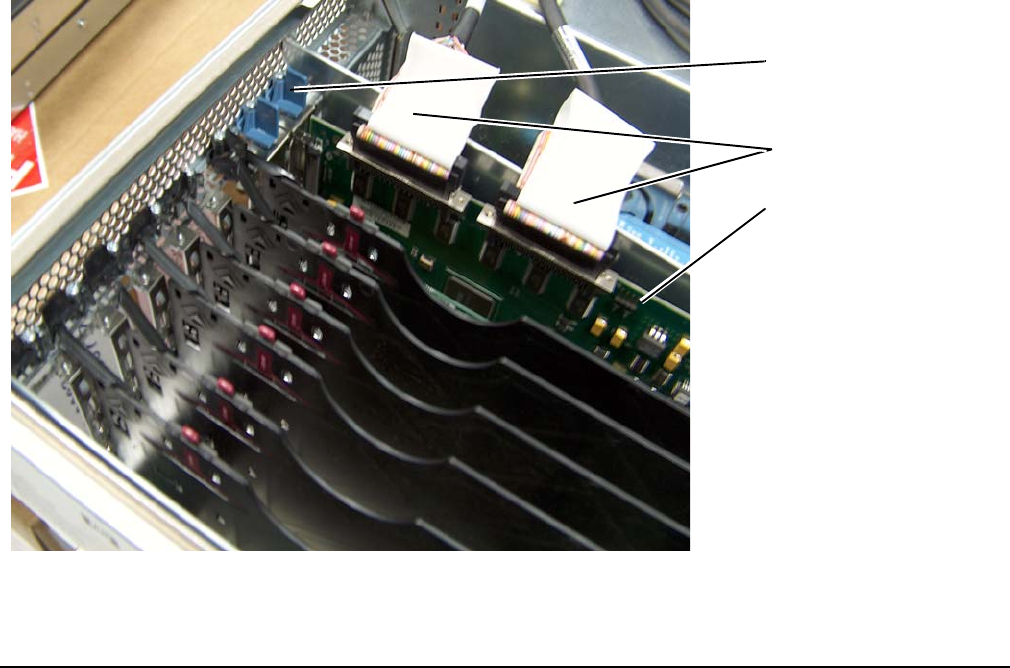
Chapter 4
Removing and Replacing Components
Removing and Replacing Core I/O Cards
86
Removing and Replacing the SCSI Core I/O Card
The HP Integrity rx4640 server has two I/O card slots that are dedicated for core I/O cards.
PCI Slot Locations and Configurations
PCI slots are numbered from 1 through 8 in your HP server. Figure 4-30 shows the core I/O card locations on
the I/O baseboard. The dedicated core I/O card slots are slots 1 and 2.
The following describes configuration requirements for slots 1 and 2:
• PCI slot 1 is dedicated for use by a SCSI HBA card. Slot 1 is not hot-plug capable. Additional PCI
expansion cards may not be placed in slot 1.
• PCI slot 2 is dedicated for use a LAN card. Slot 2 is not hot-plug capable. Additional PCI expansion cards
may not be placed in slot 2.
Removing the SCSI Core I/O Card
To remove the SCSI core I/O card in slot 1, follow these steps:
Step 1. If rack mounted, slide the HP server out from the rack until it stops. See “Extending the Server
from the Rack” on page 39.
Step 2. Remove the top cover from the chassis. See “Removing the Top Cover” on page 43.
Step 3. Disconnect any internal and external SCSI cables connected to the SCSI core I/O card.
Step 4. Open the blue PCI card latch for slot 1 by twisting it clockwise.
Figure 4-31 SCSI I/O Card Latch Location
Step 5. Remove SCSI I/O card by pulling up carefully on the SCSI I/O card.
SCSI PCI I/O card latch
for slot 1 (closed)
SCSI cables
SCSI card
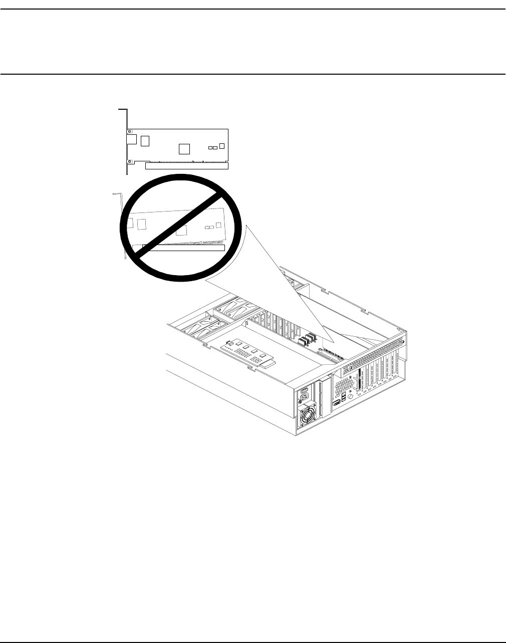
Chapter 4
Removing and Replacing Components
Removing and Replacing Core I/O Cards
87
Step 6. Install replacement SCSI I/O card. Figure 4-32 shows the correct way to install the SCSI I/O card.
CAUTION Always handle I/O cards by their edges. Failure to comply with this precaution may
result in damage to the card.
Ensure that you fully seat the card into the slot or the card may be damaged when
power is re-applied to the slot.
Figure 4-32 Inserting SCSI I/O Card
Step 7. Close the blue PCI card latch for slot 1 by twisting it counter-clockwise.
Step 8. Reconnect the internal and external SCSI cable(s) to the SCSI core I/O card.
Step 9. Replace the top cover. See “Replacing the Top Cover” on page 44.
Step 10. Push the HP server back into the rack until it stops. “Inserting the Server into the Rack” on
page 39.
Back of server
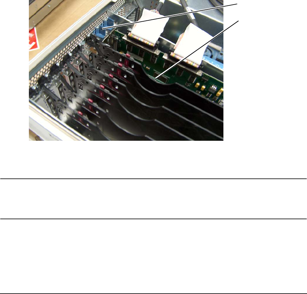
Chapter 4
Removing and Replacing Components
Removing and Replacing Core I/O Cards
88
Removing and Replacing the LAN Core I/O Card
Removing the LAN Core I/O Card
To remove the LAN core I/O card in slot 2, follow these steps:
Step 1. If rack mounted, slide the HP server out from the rack until it stops. See “Extending the Server
from the Rack” on page 39.
Step 2. Remove the top cover from the chassis. See “Removing the Top Cover” on page 43.
Step 3. Disconnect any LAN cables connected to the LAN core I/O card.
Step 4. Open the blue PCI card latch for slot 2 by twisting it clockwise.
Figure 4-33 LAN I/O Card Latch Location
Step 5. Remove LAN I/O card by pulling up carefully on the LAN I/O card.
Step 6. Install replacement LAN I/O card. Figure 4-32 shows how to install the LAN I/O card correctly.
CAUTION Always handle I/O cards by their edges. Failure to comply with this precaution may
result in damage to the card.
Ensure that you fully seat the card into the slot or the card may be damaged when
power is re-applied to the slot.
Step 7. Close the blue PCI card latch for slot 2 by twisting it counter-clockwise.
Step 8. Reconnect the LAN cable(s) to the LAN core I/O card.
Step 9. Replace the top cover. “Replacing the Top Cover” on page 44.
Step 10. Push the HP server back into the rack until it stops. “Inserting the Server into the Rack” on
page 39.
for slot 2 (closed)
LAN PCI I/O card latch
LAN PCI Card
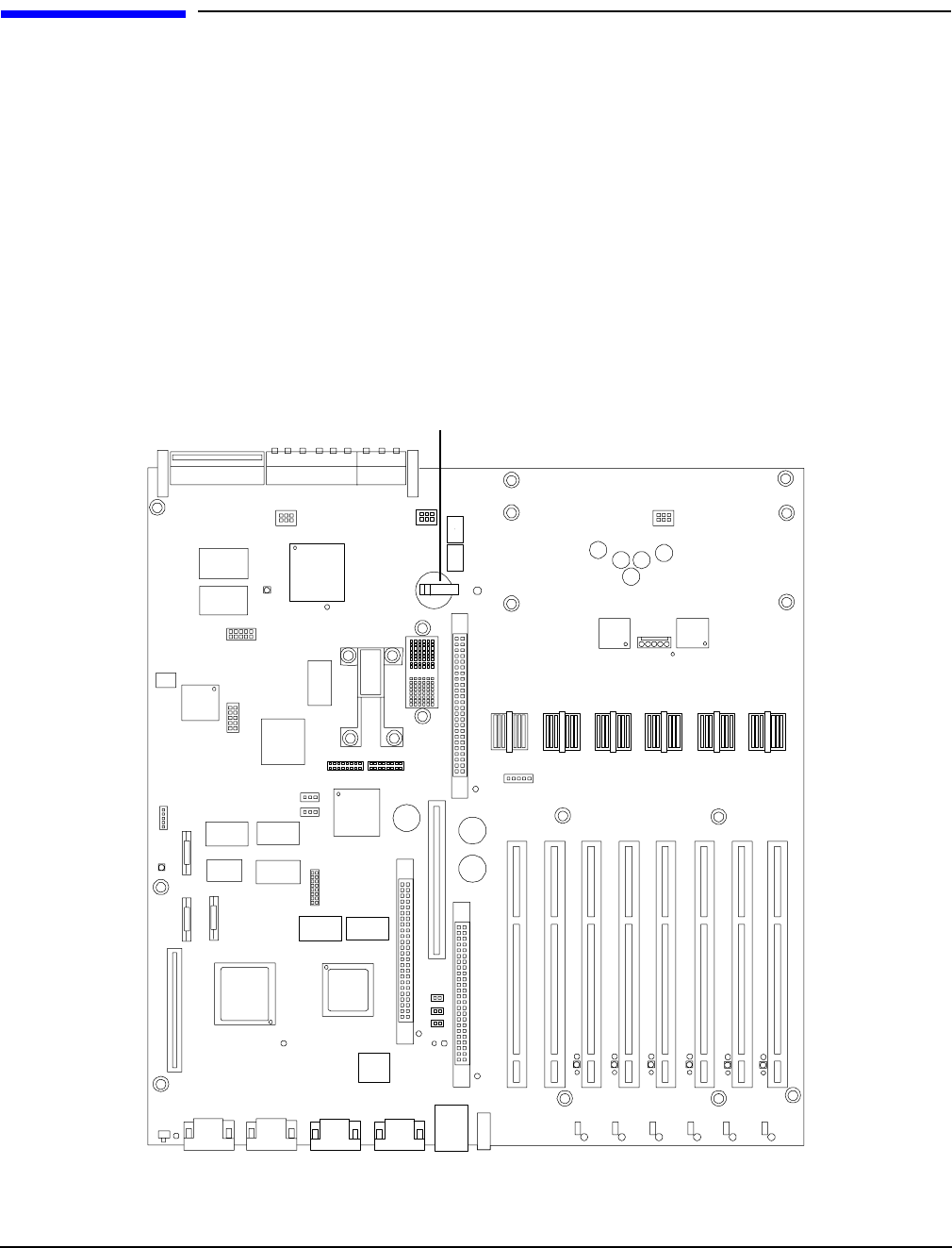
Chapter 4
Removing and Replacing Components
Removing and Replacing the Server Battery
89
Removing and Replacing the Server Battery
The server battery may be replaced by removing the top cover and accessing the I/O baseboard.
To remove and replace the server battery, follow these steps:
Step 1. If rack mounted, slide the HP server out from the rack until it stops. See “Extending the Server
from the Rack” on page 39.
Step 2. Remove the top cover from the chassis. See “Removing the Top Cover” on page 43.
Step 3. Remove the I/O baseboard assembly from the chassis. See “Removing the I/O Baseboard” on
page 66.
Step 4. Locate the battery on the I/O baseboard. Remove the battery by lifting the retaining clip and pull
the battery from its socket.
Figure 4-34 Battery Location on the I/O Baseboard
Step 5. Install the new battery.
Battery

Chapter 4
Removing and Replacing Components
Removing and Replacing Hard Disk Drives
90
NOTE The positive terminal of the battery is designated by the “+” sign. The battery is installed with the
“+” sign facing up.
Step 6. Replace the I/O baseboard assembly. See “Replacing the I/O Baseboard” on page 68.
Step 7. Replace the top cover. See “Replacing the Top Cover” on page 44.
Step 8. If rack mounted, slide the HP server all the way in until it stops. See “Inserting the Server into the
Rack” on page 39.
Removing and Replacing Hard Disk Drives
Use these procedures to remove and replace the hot-plug hard disk drives in your HP Integrity rx4640 server.
The two hot-plug hard disk drives are located in the front of the server. Figure 4-35
CAUTION A hot-plug device may require interaction with the operating system before the device can be
safely removed from or installed into the server. Verify that the operating system supports
removing/replacing disk drives while the operating system is running. If the operating system
does not support this feature, shut down the operating system before attempting this
procedure. Failure to observe this caution results in server failure.
NOTE The replacement disk drive must be the same product ID as the disk drive that is being
replaced.
HP often uses different manufacturers for disks that have the same product number. Since
they have the same product number, the replacement disk drive has the same capacity and
block size as the defective disk.
Removing a Hard Disk Drive
To remove a hot-plug disk drive, follow these steps:
Step 1. Place your finger in the lever on the latch of the selected disk drive.
Step 2. Push the tab to the right with your thumb to unlock the lever.
Step 3. Pull the lever out until the hard disk drive slides out of the server. Figure 4-36 shows how to
remove a hard disk drive.
Replacing a Hard Disk Drive
One additional hot-plug disk drive may be added to your HP server in slot 2. Always use low profile disk
drives (1.0” height) in your server. Figure 4-35 shows the slot locations on the from of the server.
To install a hot-plug disk drive, follow these steps:
Step 1. Slide the hot-plug hard disk into slot 1 until it is seated. Figure 4-36 shows how to install the hard
disk drive.
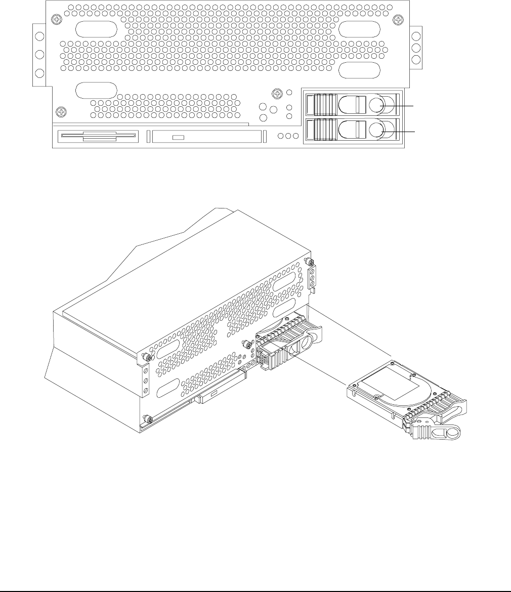
Chapter 4
Removing and Replacing Components
Removing and Replacing Hard Disk Drives
91
Step 2. Close the drive-ejector handle by pushing it down until it clicks.
Step 3. The hot-plug disk drive is now correctly installed.
Figure 4-35 Hard Disk Drive and Slot Locations on the Front of the Server
Figure 4-36 Removing and Replacing a Hard Disk Drive in Slot 2
Slot 2-SCSI ID 1
Slot 1-SCSI ID 0
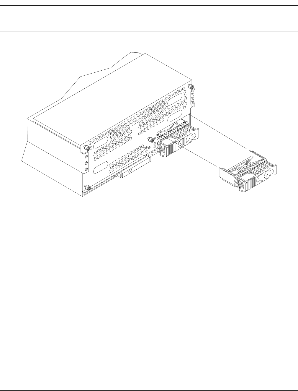
Chapter 4
Removing and Replacing Components
Removing and Replacing Hard Disk Drives
92
NOTE If you are only removing a hard disk drive and not replacing it with another one, you must
install a volume filler into the empty slot. Figure 4-37 shows how to install a volume filler in
slot 2 of the server.
Figure 4-37 Installing a Volume Filler in Slot 2

Chapter 4
Removing and Replacing Components
Removing and Replacing the SCSI Backplane Board
93
Removing and Replacing the SCSI Backplane Board
Use these procedures to remove and replace the SCSI backplane board. The SCSI backplane board is
attached to the rear of the disk media housing at the front, right side of the chassis.
WARNING Ensure that the server is powered down and all power sources have been
disconnected from the server prior to removing or replacing the SCSI backplane.
Voltages are present at various locations within the server whenever an ac power
source is connected. This voltage is present even when the main power switch is in
the off position.
Failure to observe this warning could result in personal injury or damage to
equipment.
CAUTION Failure to properly complete the steps in this procedure may result in erratic server behavior or
server failure. For assistance with this procedure contact your local HP Authorized Service
Provider.
Observe all ESD safety precautions before attempting this procedure. Failure to follow ESD
safety precautions could result in damage to the server.
Removing the SCSI Backplane Board
To remove the SCSI backplane, follow these steps:
Step 1. If rack mounted, slide the HP server out from the rack until it stops. See “Extending the Server
from the Rack” on page 39.
Step 2. Remove the front bezel. See “Removing the Front Bezel” on page 41.
Step 3. Remove the front cover. See “Removing the Front Cover” on page 42.
Step 4. Remove the top cover. See “Removing the Top Cover” on page 43.
Step 5. Remove the memory extender board. See “Removing the Memory Extender Board” on page 44.
Step 6. Remove the processor extender board. See “Removing the Processor Extender Board” on page 52.
Step 7. Remove the two hot-plug disk drives. See “Removing a Hard Disk Drive” on page 90.
Step 8. Unplug the internal SCSI cable(s) from the SCSI backplane board.
Step 9. Unplug the SCSI backplane-to-midplane riser cable from the SCSI backplane.
Step 10. Using your finger, turn the swivel latch on top of the hot-plug hard disk drive cage to unlatch the
SCSI backplane board from the hard disk cage.
Step 11. Grasp the top edge of the SCSI backplane board and pull up until it releases from the keyway slots
on the back of the hot-plug disk drive cage.
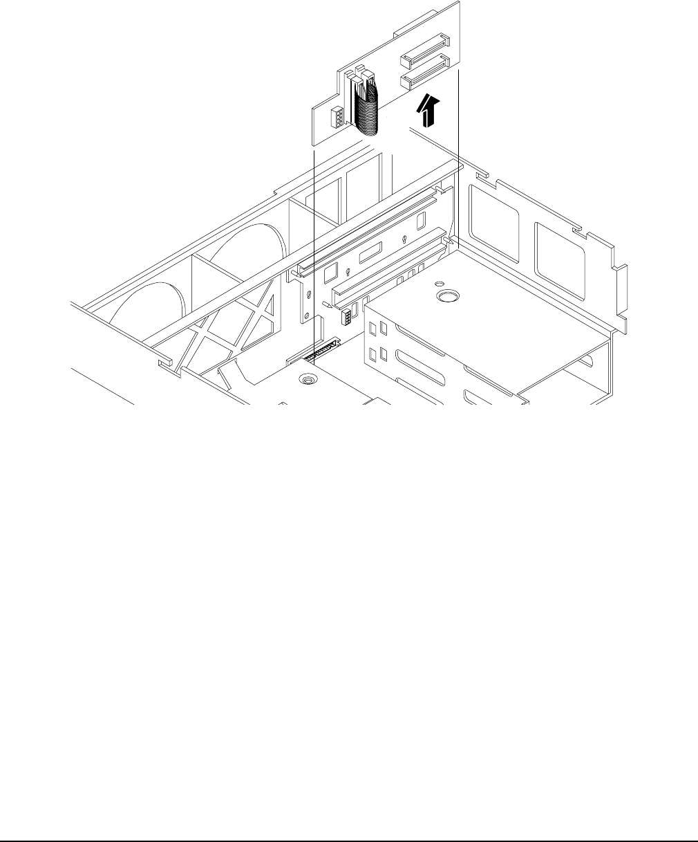
Chapter 4
Removing and Replacing Components
Removing and Replacing the SCSI Backplane Board
94
Step 12. Push the SCSI backplane board away from the disk drive cage and lift it up and out of the chassis.
Figure 4-38 shows how to remove the SCSI backplane.
Figure 4-38 Removing and Replacing the SCSI Backplane Board
Replacing the SCSI Backplane Board
To replace the SCSI backplane, follow these steps:
Step 1. Replace the SCSI backplane to the rear of the disk drive cage.
Step 2. Replace the two hot-plug disk drives into the disk drive cage. See “Replacing a Hard Disk Drive” on
page 90.
Step 3. Plug in the SCSI backplane-to-midplane cable back into the SCSI backplane.
Step 4. Plug in the internal SCSI cable into the SCSI back plane.
Step 5. Replace the processor extender board. See “Replacing the Processor Extender Board” on page 54.
Step 6. Replace the memory extender board. See “Replacing the Memory Extender Board” on page 46.
Step 7. Replace the top cover. See “Replacing the Top Cover” on page 44.
Step 8. Replace the front cover. See “Replacing the Front Cover” on page 43.
Step 9. Replace the front bezel. See “Replacing the Front Bezel” on page 41.
Step 10. If rack mounted, slide the HP server back into the rack until it stops. See “Inserting the Server into
the Rack” on page 39.

Chapter 4
Removing and Replacing Components
Removing and Replacing the Midplane Riser Board
95
Removing and Replacing the Midplane Riser Board
The midplane riser board is attached to the main bulkhead in the center of the chassis.
WARNING Ensure that the server is powered down and all power sources have been
disconnected from the server prior to removing or replacing the midplane riser
backplane.
Voltages are present at various locations within the server whenever an ac power
source is connected. This voltage is present even when the main power switch is in
the off position.
Failure to observe this warning could result in personal injury or damage to
equipment.
CAUTION Failure to properly complete the steps in this procedure will result in erratic server behavior or
server failure. For assistance with this procedure contact your local HP Authorized Service
Provider.
Observe all ESD safety precautions before attempting this procedure. Failure to follow ESD
safety precautions could result in damage to the server.
Removing the Midplane Riser Board
To remove the midplane riser board, follow these steps:
Step 1. If rack mounted, slide the HP server out from the rack until it stops. See “Extending the Server
from the Rack” on page 39.
Step 2. Remove the front bezel. See “Removing the Front Bezel” on page 41.
Step 3. Remove the front cover. See “Removing the Front Cover” on page 42.
Step 4. Remove the top cover. See “Removing the Top Cover” on page 43.
Step 5. Remove the memory extender board. See “Removing the Memory Extender Board” on page 44.
Step 6. Remove the processor extender board. See “Removing the Processor Extender Board” on page 52.
Step 7. Remove the 3 chassis hot-swap fan units. See “Removing a Hot-Swap Chassis Fan Unit” on page 63.
Step 8. Remove the I/O baseboard assembly. See “Removing the I/O Baseboard” on page 66.
Step 9. Remove the SCSI backplane board. See “Removing the SCSI Backplane Board” on page 93.
Step 10. Unplug the power distribution board power cable and signal cable from the midplane riser board.
Step 11. Unplug the DVD relay board and front panel display board cable from the midplane riser board.
Step 12. Unplug the QuickFind diagnostic board cable from the midplane riser board.
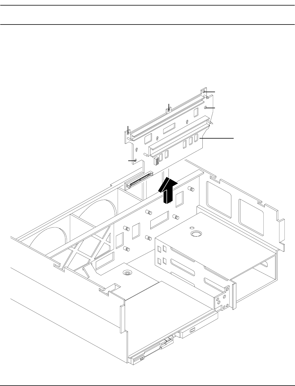
Chapter 4
Removing and Replacing Components
Removing and Replacing the Midplane Riser Board
96
NOTE At this point, all cables and connectors should be unplugged from the midplane riser
board.
Step 13. Using a torx #15 driver, remove the five torx screws attaching the midplane riser board to the
chassis.
Step 14. Grasp the top edge of the midplane riser board and lift straight up to release it from the keyway
slots on the chassis. Then pull straight out and up to remove the midplane riser board from the
chassis. Figure 4-39 shows how to remove the midplane riser board.
Figure 4-39 Removing and Replacing the Midplane Riser Board
2
4
1
5
3
Midplane riser
board
1-5
Attaching screw
locations

Chapter 4
Removing and Replacing Components
Removing and Replacing the Midplane Riser Board
97
Replacing the Midplane Riser Board
To replace the midplane riser board, follow these steps:
Step 1. Replace the midplane riser board onto the keyway slots on the chassis wall. Then push straight
down until it seats onto the locking studs. Figure 4-39 shows how to install the midplane riser
board.
Step 2. Using a torx #15 driver, replace and tighten the 5 torx screws attaching the midplane riser board to
the chassis.
Step 3. Plug in the QuickFind diagnostic board cable to the midplane riser board.
Step 4. Plug in the DVD relay board and front panel display board cable to the midplane riser board.
Step 5. Plug in the power distribution board power cable and signal cable to the midplane riser board.
Step 6. Replace the SCSI backplane board. See “Replacing the SCSI Backplane Board” on page 94.
Step 7. Replace the I/O baseboard assembly. See “Replacing the I/O Baseboard” on page 68.
Step 8. Replace the three chassis hot-swap fan units. See “Replacing a Hot-Swap Chassis Fan Unit” on
page 65.
Step 9. Replace the processor extender board. See “Replacing the Processor Extender Board” on page 54.
Step 10. Replace the memory extender board. See “Replacing the Memory Extender Board” on page 46.
Step 11. Replace the top cover. See “Replacing the Top Cover” on page 44.
Step 12. Replace the front cover. See “Replacing the Front Cover” on page 43.
Step 13. Replace the front bezel. See “Replacing the Front Bezel” on page 41.
Step 14. If rack mounted, slide the HP server back into the rack until it stops. See “Inserting the Server into
the Rack” on page 39.

Chapter 4
Removing and Replacing Components
Removing and Replacing the Power Supplies
98
Removing and Replacing the Power Supplies
The HP Integrity rx4640 server has two 200-240 VAC hot-swap power supply units (PSU). These PSUs are
located at the rear of the HP server. The supported configuration of the HP Integrity rx4640 server requires a
minimum of one PSU installed.
CAUTION Observe all ESD safety precautions before attempting this procedure. Failure to follow ESD
safety precautions could result in damage to the server.
NOTE A hot-swap device does not require interaction with the operating system before the device is
removed from or installed into the server.
The ac power to the server does not have to be off to remove or replace a hot-swap power supply.
Power Supply Load Order
The supported configuration of your HP Integrity rx4640 server requires a minimum of one 200-240 VAC
PSU. A second, optional hot-swap PSU, may be installed to provide N+1 capability. Each PSU requires a
separate power cord.
The left side (viewing from the rear) hot-swap PSU is identified as P 0, the second hot-swap power supply is
identified as P 1. Each hot-swap PSU requires a separate power cord be installed in the appropriate power
cord receptacle and attached to a power cord support bracket.
CAUTION The empty hot-swap PSU slot P 1 must remain closed with the supplied metal cover when a
second PSU is not used. Your server may be damaged due to overheating if the cover does not
remain in place.
WARNING Be careful when installing a hot-swap power supply. It is heavier than it appears.
CAUTION If the server is powered down, install the hot-swap PSU into the server before attaching the
new power cord at the rear of the server. Failure to observe this caution results in damage to
the server.
Removing a Hot-Swap Power Supply
To remove a hot-swap PSU, follow these steps:
CAUTION Be careful when removing the hot-swap power supply. It is heavier than it appears.
Step 1. If rack mounted, slide the HP server back out of the rack until it stops. See “Extending the Server
from the Rack” on page 39.
Step 2. Remove the power cord plug from the power receptacle.
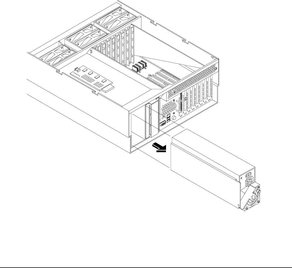
Chapter 4
Removing and Replacing Components
Removing and Replacing the Power Supplies
99
Step 3. Loosen the captive thumbscrew located at the top left of the PSU.
Step 4. Grasp the handle and pull the PSU out of the server. Figure 4-40 shows how to remove a PSU.
Replacing a Hot-Swap Power Supply
Step 1. Supporting the PSU with both hands, slide it into the empty slot until it plugs into the socket on
the internal power distribution board. Tighten the thumbscrew hand-tight.
Step 2. Install the power cord into the PSU socket.
Step 3. Apply power to the new PSU and the LED should immediately turn on.
Step 4. If rack mounted, slide the HP server back into the rack until it stops. “Inserting the Server into the
Rack” on page 39.
Figure 4-40 Removing and Replacing the Hot-Swap Power Supply

Chapter 4
Removing and Replacing Components
Removing and Replacing the Power Distribution Board
100
Removing and Replacing the Power Distribution Board
These procedures detail how to remove and replace the power distribution board in the server. The power
distribution board is attached to the rear power supply cage, underneath the hot-swap power supply fan unit.
WARNING Ensure that the server is powered down and all power sources have been
disconnected from the server prior to removing or replacing the power distribution
board.
Voltages are present at various locations within the server whenever an ac power
source is connected. This voltage is present even when the main power switch is in
the off position.
Failure to observe this warning could result in personal injury or damage to
equipment.
CAUTION Failure to properly complete the steps in this procedure results in erratic server behavior or
server failure. For assistance with this procedure contact your local HP Authorized Service
Provider.
Observe all ESD safety precautions before attempting this procedure. Failure to follow ESD
safety precautions could result in damage to the server.
Removing the Power Distribution Board
To remove the power distribution board, follow these steps:
Step 1. If rack mounted, slide the HP server out from the rack until it stops. See “Extending the Server
from the Rack” on page 39.
Step 2. Remove the top cover. See “Removing the Top Cover” on page 43.
Step 3. Remove the power supply fan unit from the chassis. See “Removing a Hot-Swap Chassis Fan Unit”
on page 63.
Step 4. Remove the hot-swap power supply(s) from the chassis. See “Removing a Hot-Swap Power Supply”
on page 98.
Step 5. Unplug the power cable and the signal cable from the midplane riser board.
Step 6. Using a torx #15 driver, loosen the one torx screw attaching the power distribution board to the
chassis.
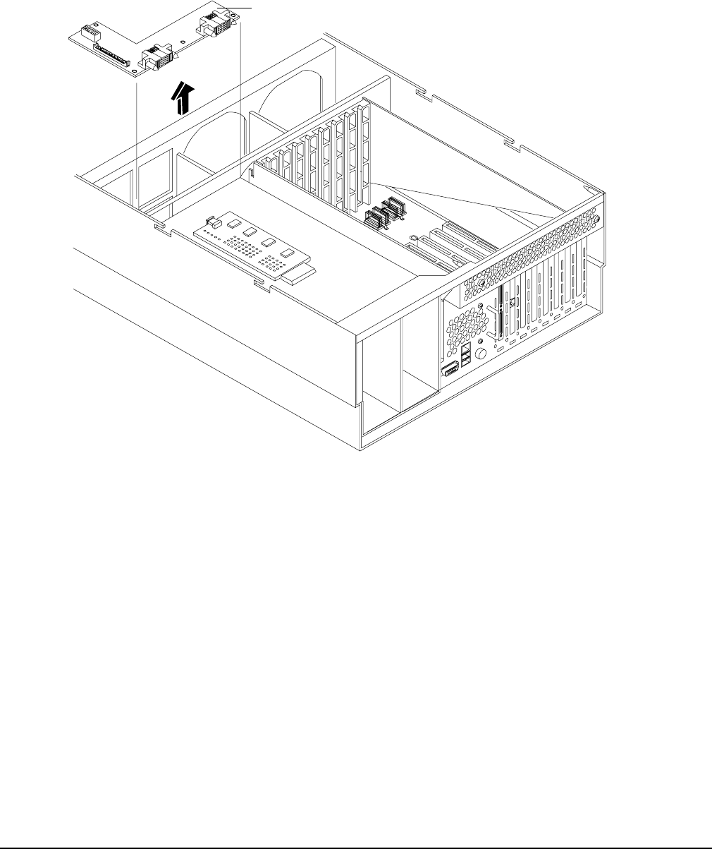
Chapter 4
Removing and Replacing Components
Removing and Replacing the Power Distribution Board
101
Step 7. Push the power distribution board towards the center of the chassis to release it from the keyway
slots. Pull it off the keyway slots and up and out of the chassis. Figure 4-41 shows how to remove
the power distribution board.
Figure 4-41 Removing and Replacing the Power Distribution Board
Replacing the Power Distribution Board
To replace the power distribution board, follow these steps:
Step 1. Replace the power distribution board over the keyway slots and push it towards the side of the
chassis to lock it onto the studs.
Step 2. Reattach the power distribution board to the chassis bulkhead by replacing the one torx #15 screw.
Tighten hand-tight.
Step 3. Plug the power and signal cables back into the midplane riser board.
Step 4. Replace the hot-swap power supply(s) into the chassis. See “Replacing a Hot-Swap Power Supply”
on page 99.
Step 5. Replace the power supply fan unit into the chassis. See “Replacing a Hot-Swap Chassis Fan Unit”
on page 65.
Step 6. Replace the top cover. See “Replacing the Top Cover” on page 44.
Step 7. If rack mounted, slide the HP server back into the rack until it stops. See “Inserting the Server into
the Rack” on page 39.
Power distribution board
Attaching
screw
hole

Chapter 4
Removing and Replacing Components
Removing and Replacing the DVD Drive
102
Removing and Replacing the DVD Drive
These procedures show how to remove and replace the DVD drive. The DVD drive is located on the front of
the HP server.
WARNING Ensure that the server is powered down and all power sources have been
disconnected from the server prior to removing or replacing a DVD drive.
Voltages are present at various locations within the server whenever an ac power
source is connected. This voltage is present even when the main power switch is in
the off position.
Failure to observe this warning could result in personal injury or damage to
equipment.
CAUTION Failure to properly complete the steps in this procedure will result in erratic server behavior or
server failure. For assistance with this procedure contact your local HP Authorized Service
Provider.
Observe all ESD safety precautions before attempting this procedure. Failure to follow ESD
safety precautions could result in damage to the server.
Removing the DVD Drive
To remove a DVD drive, follow these steps:
Step 1. Grasp the front of the DVD drive and squeeze in on the locking tab to release the drive.
Step 2. Remove the front bezel. See “Removing the Front Bezel” on page 41.
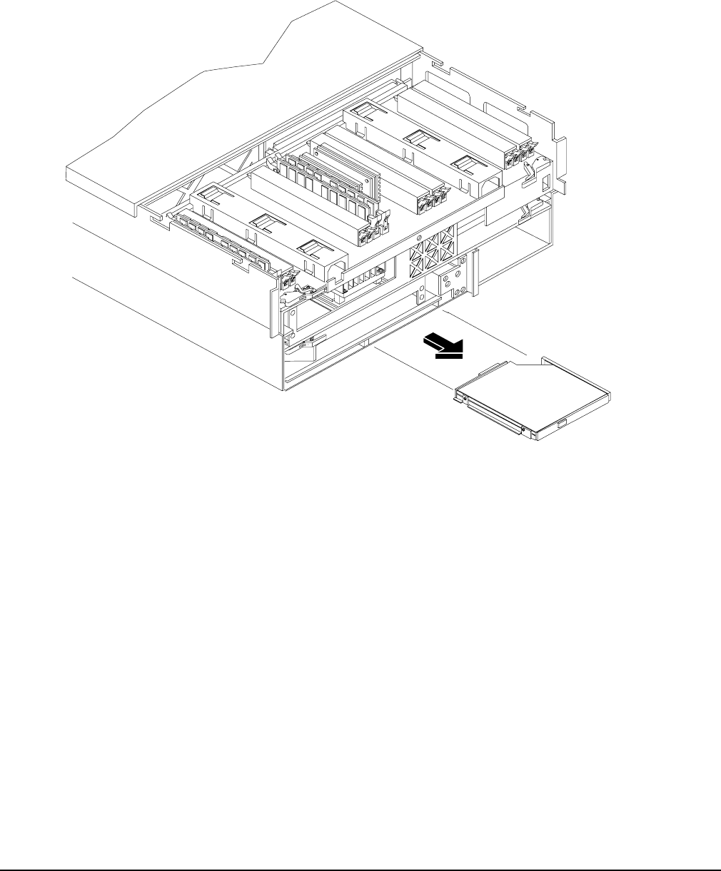
Chapter 4
Removing and Replacing Components
Removing and Replacing the DVD Drive
103
Step 3. Pull the drive straight out to remove it from the chassis. Figure 4-42 shows how to remove the DVD
drive.
Figure 4-42 Removing and Replacing the DVD Drive
Replacing the DVD Drive
To replace a DVD drive, follow these steps:
Step 1. Grasp the front of the DVD drive and squeeze in on the locking tab to release the drive.
Step 2. Push the drive straight into the drive bay until the locking tab clicks into place. Figure 4-42 shows
how to replace the DVD drive.
Step 3. Replace the front bezel. See “Replacing the Front Bezel” on page 41.

Chapter 4
Removing and Replacing Components
Removing and Replacing the DVD I/O Board
104
Removing and Replacing the DVD I/O Board
The DVD I/O board is located under a metal cover that is directly under DVD location at the front left of the
chassis.
WARNING Ensure that the server is powered down and all power sources have been
disconnected from the server prior to removing or replacing a DVD I/O board.
Voltages are present at various locations within the server whenever an ac power
source is connected. This voltage is present even when the main power switch is in
the off position.
Failure to observe this warning could result in personal injury or damage to
equipment.
CAUTION Failure to properly complete the steps in this procedure results in erratic server behavior or
server failure. For assistance with this procedure contact your local HP Authorized Service
Provider.
Observe all ESD safety precautions before attempting this procedure. Failure to follow ESD
safety precautions could result in damage to the server.
Removing the DVD I/O Board
To remove the DVD I/O board, follow these steps:
Step 1. If rack mounted, slide the HP server out from the rack until it stops. See “Extending the Server
from the Rack” on page 39.
Step 2. Remove the front bezel. See “Removing the Front Bezel” on page 41.
Step 3. Remove the front cover. See “Removing the Front Cover” on page 42.
Step 4. Remove the top cover. See “Removing the Top Cover” on page 43.
Step 5. Remove the memory extender board. See “Removing the Memory Extender Board” on page 44.
Step 6. Remove the processor extender board. See “Removing the Processor Extender Board” on page 52.
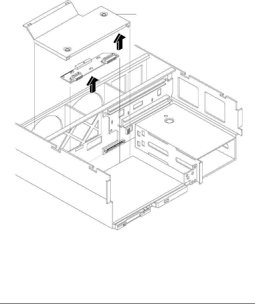
Chapter 4
Removing and Replacing Components
Removing and Replacing the DVD I/O Board
105
Step 7. Using a torx #15 driver, remove the two torx screws holding the DVD I/O board cover plate to the
chassis and remove the cover plate.
Figure 4-43 Removing and Replacing the DVD I/O Board
Step 8. Unfasten the release clip attaching the DVD I/O board to the chassis. and remove the I/O board
from the chassis.
Step 9. Lift out the DVD I/O board and remove the midplane riser board connector cable and remove the
DVD I/O board from the chassis.
Cover
DVD I/O
board

Chapter 4
Removing and Replacing Components
Removing and Replacing the DVD I/O Board
106
Replacing the DVD I/O Board
To replace the DVD I/O board, follow these steps:
Step 1. Replace the DVD I/O board into the chassis and plug in the midplane riser board connector cable.
Step 2. Replace DVD I/O board to the chassis by refastening the release clip.
Step 3. Replace the cover plate using the two torx #15 screws and a torx #15 driver.
Step 4. Replace the processor extender board. See “Replacing the Processor Extender Board” on page 54.
Step 5. Replace the memory extender board. See “Replacing the Memory Extender Board” on page 46.
Step 6. Replace the top cover. See “Replacing the Top Cover” on page 44.
Step 7. Replace the front cover. See “Replacing the Front Cover” on page 43.
Step 8. Replace the front bezel. See “Replacing the Front Bezel” on page 41.
Step 9. If rack mounted, slide the HP server into the rack until it stops. See “Inserting the Server into the
Rack” on page 39.
Chapter 4
Removing and Replacing Components
Removing and Replacing the Display Board
107
Removing and Replacing the Display Board
These procedures detail how to remove and replace the display board. The display board is located behind the
control panel and under the front cover. The display board contains the server’s on/off switch and three LEDs
that indicate server status.
WARNING Ensure that the server is powered down and all power sources have been
disconnected from the server prior to removing or replacing the display board.
Voltages are present at various locations within the server whenever an ac power
source is connected. This voltage is present even when the main power switch is in
the off position.
Failure to observe this warning could result in personal injury or damage to
equipment.
CAUTION Failure to properly complete the steps in this procedure will result in erratic server behavior or
server failure. For assistance with this procedure contact your local HP Authorized Service
Provider.
Observe all ESD safety precautions before attempting this procedure. Failure to follow ESD
safety precautions could result in damage to the server.
Removing the Display Board
To remove the display board, follow these steps:
Step 1. If rack mounted, slide the HP server out from the rack until it stops. See “Extending the Server
from the Rack” on page 39.
Step 2. Remove the front bezel. See “Removing the Front Bezel” on page 41.
Step 3. Remove the front cover. See “Removing the Front Cover” on page 42.
Step 4. Using your finger, slightly pull out the retaining tab on the chassis that holds the display board in
position.
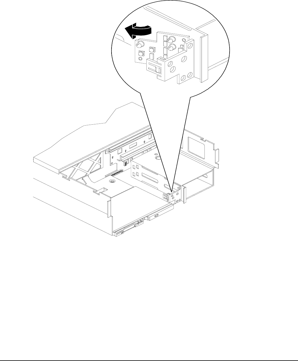
Chapter 4
Removing and Replacing Components
Removing and Replacing the Display Board
108
Step 5. Gently unplug the midplane riser board connector cable from the display board and remove the
board from the chassis. Figure 4-44 shows how to remove the display board.
Figure 4-44 Removing and Replacing the Display Board
Replacing the Display Board
To replace the display board, follow these steps:
Step 1. Gently plug in the midplane riser board cable into the display board.
Step 2. Hold the display board in position near the chassis and rotate it into the retaining clip until it clicks
into place.
Step 3. Replace the front cover. “Replacing the Front Cover” on page 43.
Step 4. Replace the front bezel. “Replacing the Front Bezel” on page 41.
Step 5. If rack mounted, slide the HP server into the rack until it stops. “Inserting the Server into the
Rack” on page 39.

Chapter 4
Removing and Replacing Components
Removing and Replacing the QuickFind Diagnostic Board
109
Removing and Replacing the QuickFind Diagnostic Board
These procedures detail how to remove and replace the QuickFind diagnostic board. The QuickFind
diagnostic board is located on top of the power supply cage, underneath the top cover.
WARNING Ensure that the server is powered down and all power sources have been
disconnected from the server prior to removing or replacing the QuickFind
diagnostic board.
Voltages are present at various locations within the server whenever an ac power
source is connected. This voltage is present even when the main power switch is in
the off position.
Failure to observe this warning could result in personal injury or damage to
equipment.
CAUTION Failure to properly complete the steps in this procedure will result in erratic server behavior or
server failure. For assistance with this procedure contact your local HP Authorized Service
Provider.
Observe all ESD safety precautions before attempting this procedure. Failure to follow ESD
safety precautions could result in damage to the server.
Removing the QuickFind Diagnostic Board
To remove the QuickFind diagnostic board, follow these steps:
Step 1. If rack mounted, slide the HP server out from the rack until it stops. See “Accessing a Rack
Mounted Server” on page 38.
Step 2. Remove the top cover. See “Removing the Top Cover” on page 43.
Step 3. Gently squeeze the cover surrounding the QuickFind diagnostic board and remove the cover/board
assembly from the top of the power supply cage.
Step 4. Turn this assembly upside down and remove the QuickFind diagnostic board from the cover.
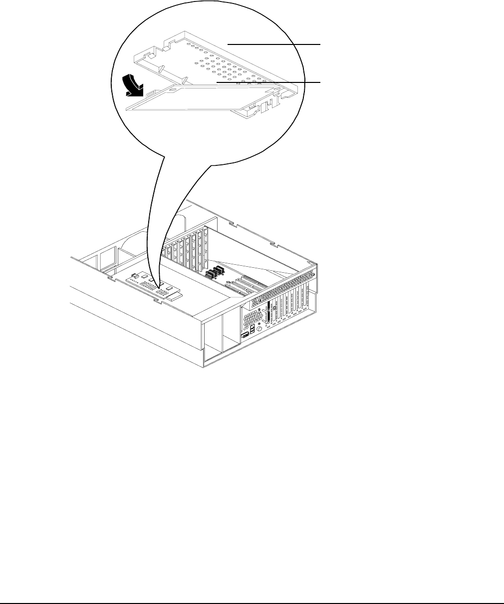
Chapter 4
Removing and Replacing Components
Removing and Replacing the QuickFind Diagnostic Board
110
Step 5. Unplug the cable from the connector on QuickFind diagnostic board and remove the board from the
chassis. Figure 4-45 shows how to remove the QuickFind diagnostic board.
Figure 4-45 Removing and Replacing the QuickFind Diagnostic Board
Replacing the QuickFind Diagnostic Board
To replace the QuickFind diagnostic board, follow these steps:
Step 1. Gently plug the cable into the QuickFind diagnostic board connector.
Step 2. Replace the QuickFind diagnostic board into the cover by snapping it into place.
Step 3. Turn the assembly over and snap into place on top of the power supply cage.
Step 4. Replace the top cover. See “Replacing the Top Cover” on page 44.
Step 5. If rack mounted, slide the HP server into the rack until it stops. See “Inserting the Server into the
Rack” on page 39.
Cover
QuickFind
diagnostic board

Chapter 5 111
5Troubleshooting
This chapter provides basic troubleshooting instructions for the HP Integrity rx4640 server.
This chapter addresses the following topics:
• “Troubleshooting Tips” on page 112
• “Possible Problems” on page 113
• “Troubleshooting Using LED Indicators” on page 116
• “Diagnostics” on page 128
• “Recommended Cleaning Procedures” on page 131
• “Where to Get Help” on page 132

Chapter 5
Troubleshooting
Troubleshooting Tips
112
Troubleshooting Tips
WARNING Before removing a cover to service components that cannot be hot-swapped, always
disconnect the ac power cords and unplug telephone cables. Disconnect telephone
cables to avoid exposure to shock hazard from telephone ringing voltages.
Disconnect the ac power cords to avoid exposure to high energy levels that may
cause burns when parts are short-circuited by metal objects such as tools or jewelry.
CAUTION Do not operate the HP server for more than two minutes with any cover (including power
supplies and disk drives) removed. Otherwise, damage to server components may result due to
improper cooling airflow.
However, you can safely remove a cover while the HP server is running to remove and replace
PCI hot-plug boards. For any other service activity requiring access to the I/O baseboard or
power distribution board, power-down the HP server and observe all safety precautions.
Troubleshooting Methodology
Step 1. This is the entry point to the troubleshooting process. Here, you pick from a set of symptoms,
ranging from very simple (server LED is blinking) to the most difficult (Machine Check Abort
[MCA]) has occurred. The following is a list of symptom examples:
• Server LED blinking
• System Alert present on console
• Server will not power-up
• Server will not boot
• Event/Error Message received
• Machine Check Abort (MCA)
Step 2. This step narrows down the observed problem to the specific troubleshooting procedure required.
Here you isolate the failure to a specific part of the server so that you can perform more detailed
troubleshooting. For example:
• Problem-Server LED blinking
— System Alert on console?
— Analyze the alert by using the system event log (SEL) to identify the last error logged by
the baseboard management controller. Use the iLO MP commands to view the SEL.
Step 3. At this point you will have a good idea about which area of the server requires further analysis. For
example, if the symptom was “server will not power-up” then the initial troubleshooting procedure
may have indicated a problem with the dc power supply not coming up after the power switch was
turned on.

Chapter 5
Troubleshooting
Possible Problems
113
Step 4. You have now reached the point where the failed Field Replaceable Unit (FRU or FRUs) have been
identified and need to be replaced. You must now perform the specific remove-and-replace
verification steps.
NOTE If multiple FRUs are identified as part of the solution, a fix cannot be guaranteed
unless all identified failed FRUs are replaced.
Step 5. There may be specific recovery procedures you need to perform to finish the repair. For example, if
the display panel is replaced, you need to restore customer-specific information.
Possible Problems
This section contains example HP server problems and their possible solutions.
The Server Does Not Power On
Step 1. Check to see if the iLO MP is working. If so, access the SEL to determine the problem.
Step 2. Check all power connection cables.
Step 3. Verify that 200-240 VAC power is available at the ac power receptacle. Check the receptacle output
with another device.
Step 4. Check the power supply fans to see if they are operating. The fans will operate off the dc voltage
generated by the power supply.
Step 5. Check that the Power LED on Front Control Panel is illuminated. See“Front Control Panel LED
Indicators” on page 117.
Step 6. Check all connections from the power supply to the power distribution module.
Step 7. Verify that all cables and modules are correctly connected. Especially check the display panel
connection.
Step 8. Review the installation procedures for the server. See the HP Integrity rx4640 Installation Guide.
Step 9. If the server starts to power-on and then power-off, a voltage rail of the power supply may be out of
specification. The BMC monitors voltages and prevents power-on when power values are out of
specification.
The Server Does Not Boot
Step 1. Examine the front panel LEDs for warning or fault indications. The server LED will be flashing
yellow with a warning indication and flashing red with a fault indication. See “Front Control Panel
LED Indicators” on page 117.
Step 2. Examine the QuickFind Diagnostic Panel for indications of specific warning or fault indications.
The diagnostic LEDs present patterns that categorize the source of the warning or fault. See
“QuickFind Diagnostic Panel LED Indicators” on page 119.

Chapter 5
Troubleshooting
Possible Problems
114
Step 3. Display and examine the system event log (SEL) and forward progress log (FPL) for further
information relating to warning or fault isolation.
Step 4. Review the firmware revisions of all firmware.
NOTE If the server does not boot to EFI, the only way to check firmware revisions is with
the iLO MP SR command. However, the result may not be accurate because the
versions it displays are updated by system firmware during the boot to EFI. If the
system firmware does not boot to the point where it updates iLO MP firmware
version, the versions displayed by the SR command may not be correct.
Step 5. Use the iLO MP command to cycle the server power: pc off, pc on, or pc -cycle.
Step 6. Turn the server off, wait at least twenty seconds, then turn the server back on to see if the failure
can be cleared.
Step 7. Check that all DIMMs are seated properly.
Step 8. Check that the DIMM configuration on the I/O baseboard matches those approved. A minimum of
one DIMM pair must be installed.
Step 9. Verify that the DIMMs are fully seated. When the DIMM is fully seated in the mating connector,
the retaining latches are closed (they should be flush with the front of the DIMM). If the latches are
not closed, reseat the DIMM fully by engaging the retaining latches and closing them fully.
Step 10. Check that the processors are installed in the correct sockets on the processor extender board. See
Figure 4-13 on page 56 for the correct processor load order.
Step 11. Verify the processors are of the same type.
Step 12. Check the boot order with the SCSI configuration utility.
Step 13. Check the switch settings on the I/O baseboard. They should match Figure 4-24 on page 69.
Step 14. If there are no obvious errors, reflash the BMC firmware. (See Appendix C, “Utilities,” on page 161.)
Step 15. If the server will still not boot, it may be necessary to replace the base unit.
The Server Has Intermittent Failures
Step 1. Examine the front panel LEDs for warning or fault indications. The server LED flashes yellow with
a warning indication and flashes red with a fault indication. See “Front Control Panel LED
Indicators” on page 117.
Step 2. Examine the QuickFind Diagnostic Panel for indications of specific warning or fault indications.
The diagnostic LEDs present patterns that categorize the source of the warning or fault. See
“QuickFind Diagnostic Panel LED Indicators” on page 119.
Step 3. Display and examine the errdump logs for further information relating to warning or fault
indications.
Step 4. Display and examine the system event log (SEL) and forward progress log (FPL) for further
information relating to warning or fault indications.
Step 5. Make sure that the server fan assemblies are fully seated.

Chapter 5
Troubleshooting
Possible Problems
115
Step 6. Verify that the server is plugged into a power source that is within specifications described on the
label of the power supply.
Step 7. Make sure that the internal SCSI chain is terminated and that termination is not enabled on any of
the drives. Note that LVD SCSI termination is provided on the cable.
Step 8. Check that the processors are installed in the correct sockets and that terminators are installed in
all unused sockets.
Step 9. Reset the main memory DIMMs.
Step 10. If date and time or customer settings are being cleared, the I/O baseboard battery may need to be
replaced.
The Server LED or Diagnostic LEDs Are Not On and No Error Messages Appear
If the server does not work (with no LEDs illuminated) and no error messages appearing, check the following:
Step 1. Make sure that all cables and the ac power cord are plugged into their proper receptacles.
Step 2. Make sure that the ac outlet is working. If the server is plugged into a switched multiple-outlet box,
make sure that the switch on the outlet box is turned on.
Step 3. Make sure that the server is turned on (the power-on light should be green and the fans should be
on).
Step 4. Turn the server off, wait at least twenty seconds, then turn the server back on to see if the failure
can be cleared.
Step 5. Make sure that all boards are installed properly and the processors are installed in the correct slot.
They must be seated firmly in their slots and any cables must be connected firmly.
Step 6. If the server stopped working after you installed a new board, remove the board and turn on the
server. If your server now works, check the installation instructions received with the new board
for correct installation method. If the new board is preventing the server from powering on, it is
likely to have a serious electrical problem.
Step 7. If the server still does not work, remove all boards and options that you have installed (do not
remove the hard disk drives) and turn on the server.
Step 8. Add boards and options one at a time to determine which one is causing the problem.
Step 9. If you have added any memory, make sure that the DIMMs are seated properly in the board. Also
check the DIMM configuration, and that the DIMMs are matched pairs.
Power Shuts Off and Does Not Come Back On
When certain critical conditions exist, the server shuts down all power.
The critical conditions that may shut down the server are:
• Critical temperature fluctuations or changes
• Voltage problems (external ac line, internal dc rails))
• Power supply failure (if only one power supply is installed in the server)
• More than one fan has failed
If the server powers-off, and before you try a restart, do the following:
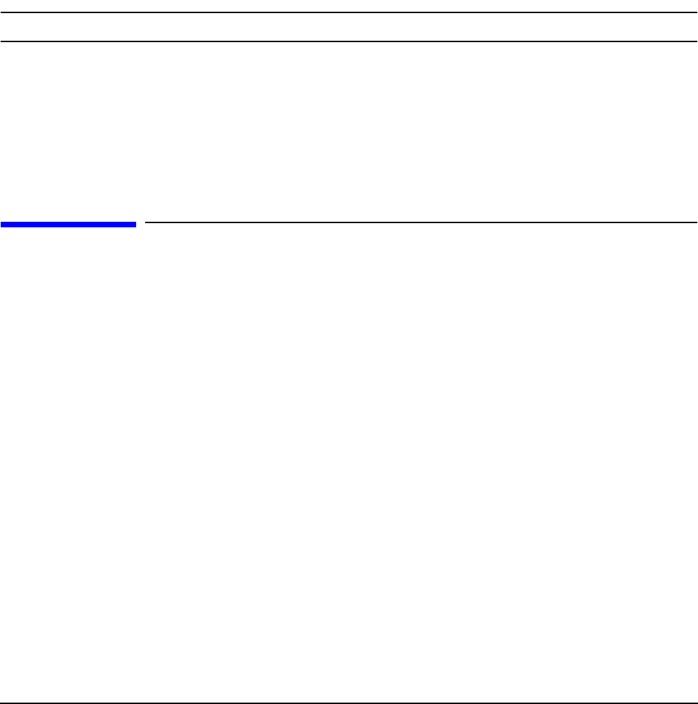
Chapter 5
Troubleshooting
Troubleshooting Using LED Indicators
116
Step 1. Examine the front panel LEDs for warning or fault indications. The server LED flashes yellow with
a warning indication and flashes red with a fault indication. See “Front Control Panel LED
Indicators” on page 117.
Step 2. Examine the QuickFind Diagnostic Panel for indications of specific warning or fault indications.
The diagnostic LEDs present patterns that categorize the source of the warning or fault. See
“QuickFind Diagnostic Panel LED Indicators” on page 119.
Step 3. Check to make sure power is getting to the server. Plug a known working device into the power
outlet.
Step 4. Check for proper ventilation for the server. The server should have at least three inches of space
around the front and rear for proper airflow when installed in a rack.
NOTE Temperature problems may be caused by a fluctuating power supply.
Step 5. Check the server specifications and make sure the environmental temperature and voltage are in
the specified guidelines.
Step 6. Monitor the server to make sure you are not experiencing further temperature and voltage
problems.
Step 7. Check the SEL for the event that caused the BMC to shut the server off.
Troubleshooting Using LED Indicators
Your HP Integrity rx4640 server has LED indicators located on the front control panel and an internal
QuickFind diagnostic panel that you can use to determine what repair action is required. For descriptions of
all LEDs on your HP Integrity rx4640 server see the HP Integrity rx4640 Operations Guide on the
documentation CD included with your server.
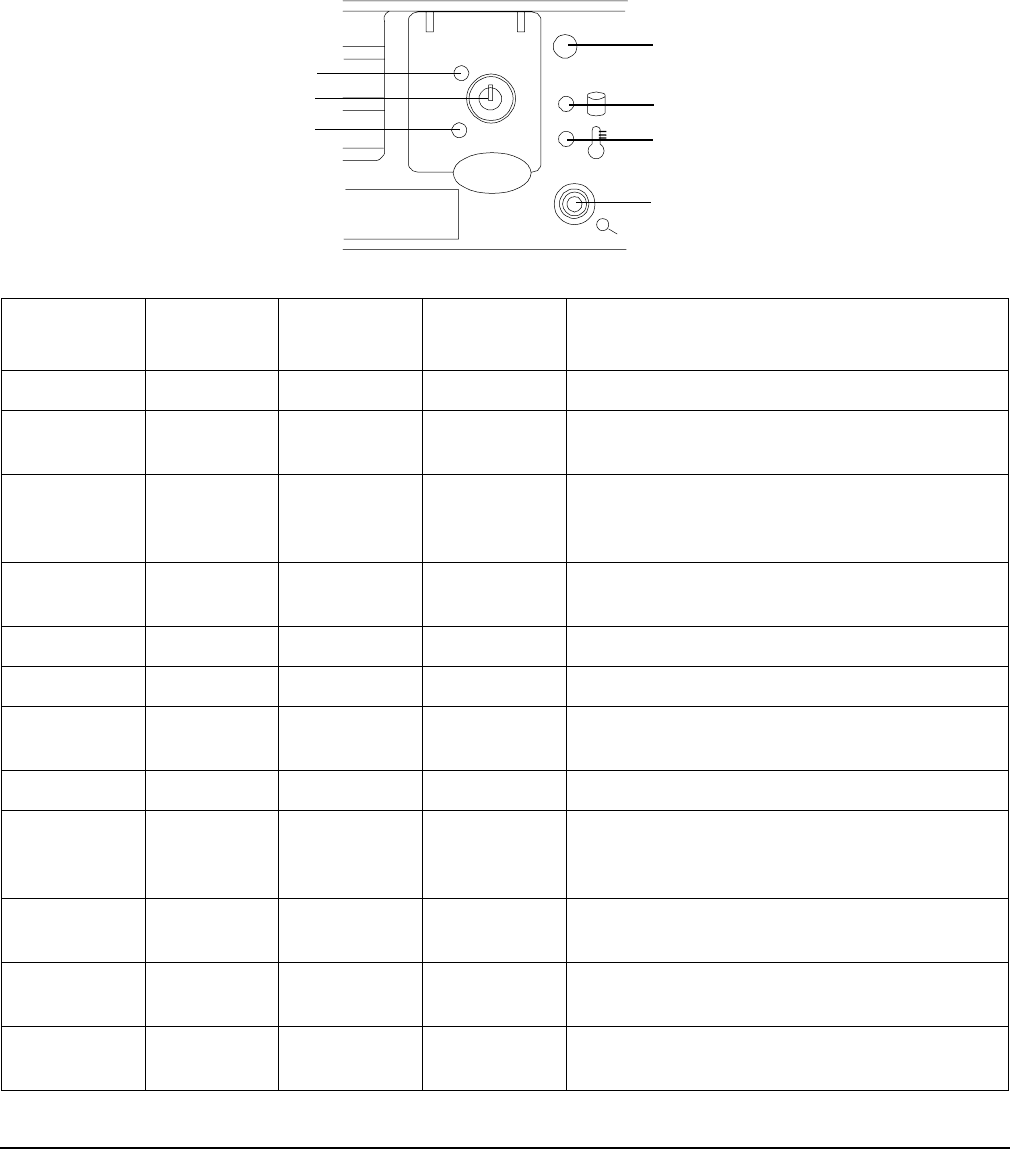
Chapter 5
Troubleshooting
Troubleshooting Using LED Indicators
117
Front Control Panel LED Indicators
The front control panel LEDs show you the server status at a glance. If warning or attention lights are
flashing, then you should to query the QuickFind diagnostic panel or management processor for further
information.
Figure 5-1 Front Control Panel
Table 5-1 Front Control Panel LED Definitions
LED/
Button State Flash Rate Color Description
Server Running Steady Green Green: Server normal-OS up and running
Server Booting Flashing at
0.5Hz
Green Flashing green: OS booting or at EFI
Server Attention Flashing at
1 Hz
Yellow Flashing yellow: Warning-server needs
attention. Redundancy lost, component
failure pending.
Server Fault Flashing at
2 Hz
Red Flashing red: hard fault, server halted
Server Off Off N/A Off: server off
Power On Steady Green Green: power normal
Power On Steady Yellow Flashing yellow: Housekeeping voltage
present
Power Off Off Off Off: Power off
Disk LED Flashing at
rate of disk
activity
Green Flashing green: disk activity
Thermal
LED
OK Steady Green Green: thermal OK
Thermal
LED
Warning Flashing at
1 Hz
Yellow Flashing yellow-thermal warning
Locator
LED/Button
Flashing at
1 Hz
Blue Flashing blue: server locator LED may be
remotely or locally activated/deactivated
Power LED
Thermal LED
TOC/NMI Button
Power Button Disk LED
Server LED
Locator
Button/LED
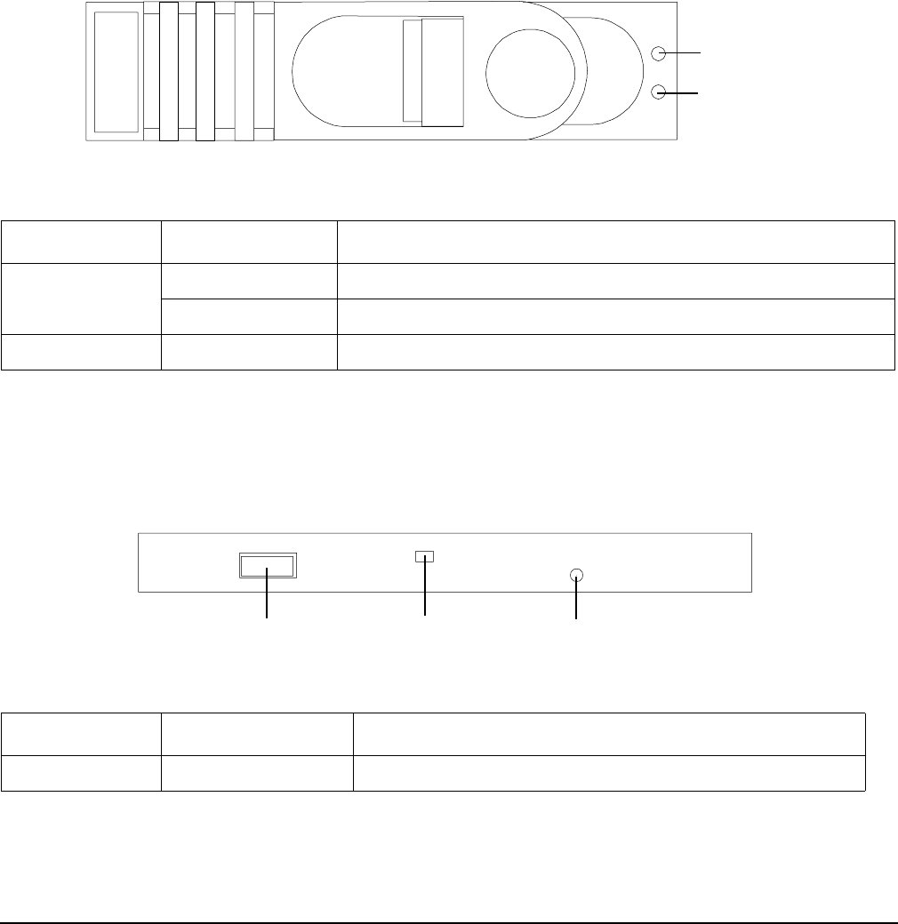
Chapter 5
Troubleshooting
Troubleshooting Using LED Indicators
118
Hard Disk Drive LED Indicators
The hot-swap disk drives have two LEDs per drive, as described below. Figure 5-2shows the location of the
hard disk drive LEDs. Definitions of the hard disk drive LEDs are detailed in Table 5-2.
• Status LED - The drive status LED displays green when disk power is on, and is off when disk power is
off.
• Activity LED - The drive activity LED is green and indicates disk drive activity. This LED is controlled by
the disk drive directly and turns on when a drive is accessed.
Figure 5-2 Hot-Swap Disk Drive LED Indicators
DVD/DVD-R/DVD-RW Drive LED Indicators
The HP server is delivered with one DVD-RM drive (DVD-R and DVD-RW optional). Each of these devices
has one activity LED as shown and described in Figure 5-3 and Table 5-3.
Figure 5-3 DVD–ROM Drive
Table 5-2 Hot-Swap Disk Drive LED Definitions
LED Color Description
Status LED Green Drive/Slot normal (drive present)
Off No power to hard disk drive
Activity LED Flashing green Drive access under hard drive control.
Table 5-3 DVD Drive LED Definitions
LED Status Description
Activity LED Flashing green Drive access under hard drive control.
Status LED
Activity LED
Eject Button Activity LED Emergency Eject
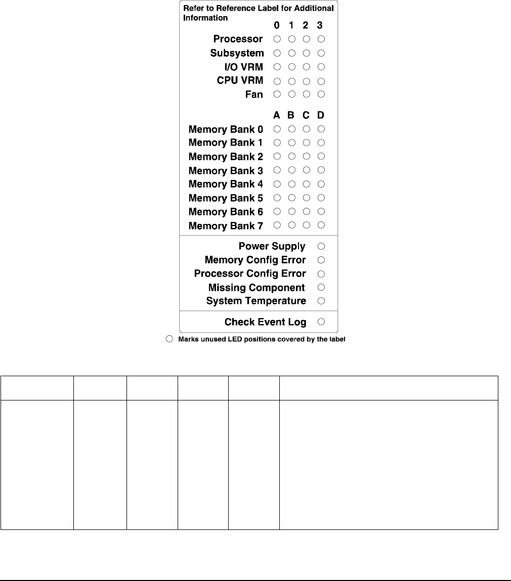
Chapter 5
Troubleshooting
Troubleshooting Using LED Indicators
119
QuickFind Diagnostic Panel LED Indicators
The QuickFind diagnostic panel is located under the top cover and is attached to the top of the power supply
cage. Figure 5-4 and Table 5-4 show and describe the status of the various LEDs and what is wrong with the
indicated component.
Figure 5-4 QuickFind Diagnostic Label
Table 5-4 QuickFind Diagnostic Panel LED Definitions
Item LED 0 LED 1 LED 2 LED3 Details
Processor Socket 0 Socket
1
Socket
2
Socket
3
If the Server LED (on front panel) is in the
attention or fault state and the processor
LED is on, then the processor or voltage
regulator has failed—the processor module
in the specified socket needs to be replaced.
If the thermal LED is in the warning or
critical state and the processor LED is on,
then the processor exceeded the warning or
critical level.

Chapter 5
Troubleshooting
Troubleshooting Using LED Indicators
120
Subsystem CPU
board
Memory
board
I/O
board
n/a A soldered voltage regulator has failed—the
specified board must be replaced.
I/O VRM 12 volt 5 volt 3 volt n/a A plug-in voltage regulator has
failed—replace I/O baseboard.
CPU VRM n/a n/a n/a n/a n/a
Fan Module 0 1 2 n/a One or both fans in a fan module have
failed—the module must be replaced.
Fan 2 is in front of the power supplies.
Memory
Bank X (0-7)
DIMM
xA
DIMM
xB
DIMM
xC
DIMM
xD
The specified DIMM has failed—the DIMM
must be replaced.
If all the LEDs for a rank (0-7) are lit and
the memory config error LED is lit, then the
DIMMs in the specified rank are
mismatched—replace mismatched DIMM.
Check
Power
Supply
n/a n/a n/a One of the power supply or power supply
fans have failed—replace the power supply.
The faulty power supply LED (located on
Power supply) will be lit.
Memory
Config Error
n/a n/a n/a The DIMMs in a rank are mismatched. All
the DIMMs in the specified rank (0-7) will
be lit.
Processor
Config Error
n/a n/a n/a The processors are mismatched—replace
mismatched processor.
Missing
Component
n/a n/a n/a A required component(s) is not installed in
the server and thus preventing “power-up.”
Server Temp n/a n/a n/a The internal temperature of the server has
exceeded the warning or critical level.
Check Event
Log
n/a n/a n/a An event has occurred that requires
attention.
Table 5-4 QuickFind Diagnostic Panel LED Definitions (Continued)
Item LED 0 LED 1 LED 2 LED3 Details
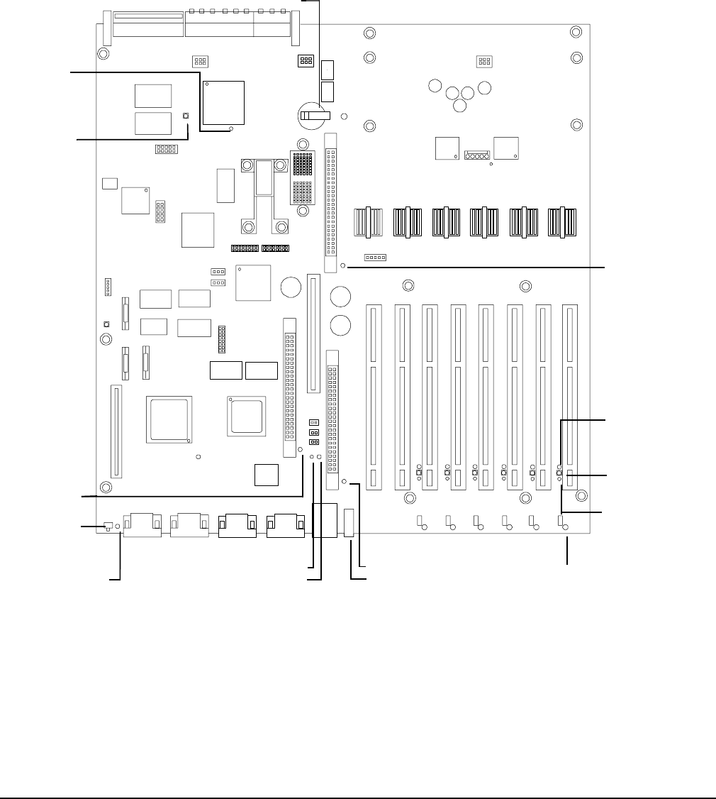
Chapter 5
Troubleshooting
Troubleshooting Using LED Indicators
121
I/O Baseboard LED Indicators
Figure 5-5 shows the various LEDs, sensors, and reset or attention buttons found on the I/O baseboard.
Table 5-5 describes the status of the various LEDs on the I/O baseboard.
Figure 5-5 I/O Baseboard LEDs, Buttons and Sensors
PCI Attention
LED 6X
PCI Attention
Button (Doorbell
)
6X
PCI Attention LED 6X
3.3VSB
Power
LED
12V VRM LED
3.3V VRM LED
5V VRM
LED
MP Heartbeat LED
Battery
BMC
Reset
Button
MP Soft
Reset
Button
MP Self-Test
LED BMC Heartbeat LED Locator Button/LED
PCI Power LED
6X

Chapter 5
Troubleshooting
Troubleshooting Using LED Indicators
122
Table 5-5 I/O Baseboard LEDs, Buttons and Sensors
LED/Button Color Status Condition
12 V VRM Power
LED
Green On 12 V VRM is functioning.
5 V VRM Power
LED
Green On 5 V VRM is functioning.
3.3 V VRM Power
LED
Green On 3.3 V VRM is functioning.
iLO MP Heartbeat Green Blinking The management processor is functioning
correctly.
iLO MP Self Test
LED
Amber On
Off
The management processor is executing the
internal self test.
The management processor has passed the
internal self test.
BMC Heartbeat Green Blinking The baseboard management controller is
functioning correctly.
3.3 VSB Power
LED
Green On Standby power is available.
iLO MP Soft Reset
Button
N/A Press Resets the management processors values.
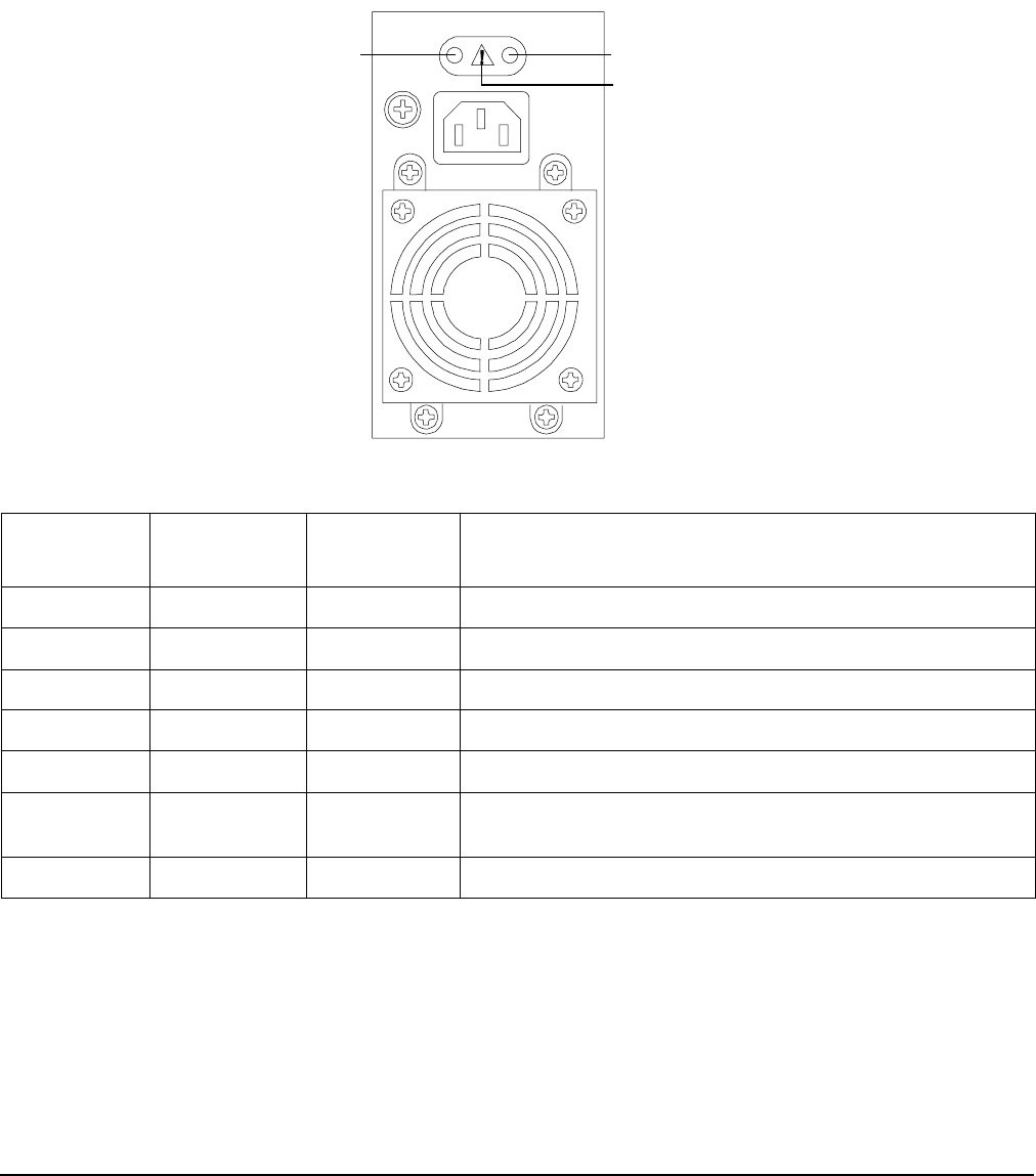
Chapter 5
Troubleshooting
Troubleshooting Using LED Indicators
123
Power Supply Status LED Indicators
Each of the two 200-240 VAC power supply unit has three status LEDs located on the back of the power
supply on the rear panel. Consolidated status of all power supplies is reported by the front control panel by
the power status LED.
Figure 5-6 Power Supply Status LED
iLO MP LAN Port Link/Activity LED Display
The iLO MP LAN uses an RJ-45 type connector. This connector has two LEDs (LAN link and LAN activity)
that signal status and activity.
Two versions of the iLO MP card exist for this server. Depending on which version of the card is installed in
the server, the iLO MP LAN port LEDs display differently.
Table 5-6 Power Supply Status LED
Power
LED-Green
Predict Fail
LED-Amber
Fail
LED-Amber Status
Off Off Off No ac power applied to all PSUs.
Off Off On No ac power applied to this PSU only.
Blinking Off Off ac present/standby outputs on.
On Off Off PSU dc outputs on and OK.
Off Off On Power supply failure.
On Blinking Off Predictive failure—PSU about to fail because of poorly
performing fan.
On Off Blinking Current limit on 48 VDC output.
Predict Fail
LED-Amber Power LED-Green
Fail LED-Amber
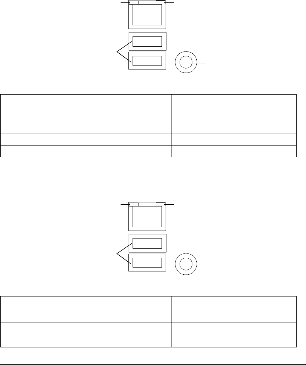
Chapter 5
Troubleshooting
Troubleshooting Using LED Indicators
124
On some servers, the LEDs display as follows:
Figure 5-7 iLO MP LAN LEDs
On other servers, the LEDs display as follows:
Figure 5-8 iLO MP LAN LEDs
Table 5-7 iLO MP LED Status Descriptions
LED Condition Status
100M amber On Linked at 100MBps. No activity
100M amber Blinking Linked at 100MBps. Activity present
10M green On Linked at 10MBps. No activity
10M green Blinking Linked at 10MBps. Activity present
Table 5-8 iLO MP LED Status Descriptions
LED Condition Status
100M green On Linked at 100MBps. No activity
100M green Blinking Linked at 100MBps. Activity present
10M amber On Linked at 10MBps. No activity
100M Link/Activity, Amber LED 10M Link/Activity, Green LED
Locator Button and LED
USB Ports
100M Link/Activity, Green LED 10M Link/Activity, Amber LED
Locator Button and LED
USB Ports

Chapter 5
Troubleshooting
Troubleshooting Using LED Indicators
125
Locator LED and Button
An LED and button is provided on the rear panel of the server. Another single blue LED and button is on the
front control panel that enables/disables the locator function. See Figure 5-7 for the locator LED and button
location.
10M amber Blinking Linked at 10MBps. Activity present
Table 5-8 iLO MP LED Status Descriptions (Continued)
LED Condition Status
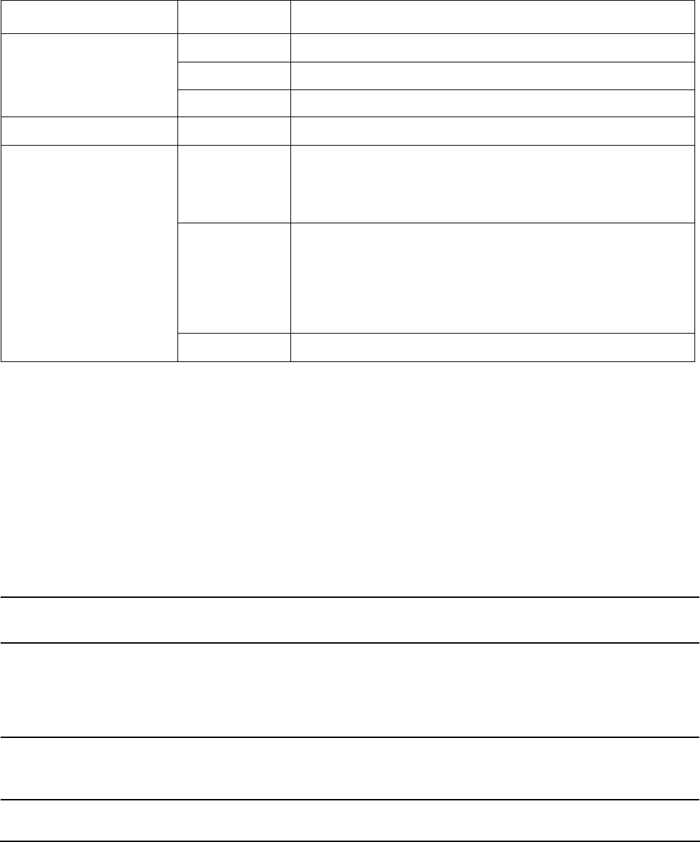
Chapter 5
Troubleshooting
Troubleshooting Using LED Indicators
126
PCI-X LEDs and Hardware Errors
The following table describes the hot-plug PCI-X LED error conditions.
Troubleshooting PCI-X Hot-Plug Operations
Sometimes a PCI-X card will not come online during a hot-plug operation due to a frequency mismatch
between the PCI-X card and the slot bus or due to other hardware errors. To determine the type of error you
are experiencing, observe the LED activity as described below. For a full understanding and description of
HP-UX 11i v2 hardware errors, read Interface Card OL* Support for HP-UX Servers and Workstations,
Important Considerations at http://docs.hp.com.
1. PCI-X Bus Mode or Frequency Mismatch
After you insert a PCI-X card into the slot and push the attention button, the power LED goes from
blinking to steady-off and stays at steady-off; this means that the server firmware has rejected the PCI-X
card, and indicates either bus frequency or bus mode mismatch.
NOTE After pushing the attention button, ensure that you wait the full duration of the 5 second
operation cancellation window before taking further action.
2. Hardware Operation Fault
If the PCI-X card cannot be powered on during a hot-plug addition operation, the attention LED turns
steady-on and the power LED turns steady-off.
CAUTION If your card does not power up, the power loss may be due to the existing PCI-X expansion
cards using all the available power. Check the power ratings of your existing PCI-X cards.
A known cause of power loss is the use of more than 3 RAID cards in your server.
Table 5-9 PCI-X LED Descriptions
Power LED-Green Condition Description
On PCI-X slot is powered on.
Blinking Hot-plug operation in progress—do not touch the slot.
Off PCI-X slot is powered off.
Attention LED-Amber Condition Description
On Hardware operational fault.
NOTE: If slot is powered on, it will not power off. If slot is
powered off, it will not power on.
Blinking Slot location being indicated.
NOTE: If you want to learn how to activate the attention
LED into the blinking/indicator state, read Interface Card
OL* Support for HP-UX Servers and Workstations, Turning
Attention LED to Blink or Off at http://docs.hp.com.
Off If power to slot is on, the slot is functioning normally.

Chapter 5
Troubleshooting
Troubleshooting Using LED Indicators
127
If the PCI-X card cannot be powered off during a hot-plug removal operation, the attention button turns
steady-on and the power LED remains steady-on.
CAUTION If your slot does not power off during a hot-plug removal operation, do not open the manual
retention latch (MRL) on the OLX divider. This action may cause a server failure or an
operating system crash.

Chapter 5
Troubleshooting
Diagnostics
128
Diagnostics
A suite of offline and online support tools are available to enable manufacturing, field support personnel, and
you to troubleshoot server problems. In general, if the operating system (HP-UX) is already running, it is best
not to shut it down. Use the online support tools.
If the OS cannot be booted, use the offline support tools to resolve the problem. The offline support tools are
available from the EFI partition. Once you resolve the problem preventing booting, boot HP-UX, and use the
online support tools for any further testing.
If it is not possible to reach the EFI from either the main disk or from LAN, you must troubleshoot, using the
visual fault indicators, console messages, and system error logs that are available.
Online Diagnostics/Exercisers
Online support tools are provided under both operating systems. Centralized error archiving and hardware
inventory tools for both OSes are available as long as the agents/providers that support them are installed on
the managed server.
On HP-UX systems, the legacy tools within OnlineDiag continue to be supported. The online support tools, on
HP-UX 11.23 and greater, include the Support Tool Manager (STM) tools, and the additional Web-Based
Enterprise Management (WBEM) features added by SysFaultMgmt.
The STM suite of tools includes verifiers, diagnostics, exercisers, information modules, and expert tools.
Verifiers quickly determine whether or not a specific device is operational by performing tasks similar in
nature to the way applications use the device. No license is required to run the verifiers.
Diagnostics are tools designed to identify faulty or failed FRUs.
Exercisers stress devices in order to facilitate the reproduction of intermittent problems.
Information modules create a log of information specific to one device, including:
• The product identifier
• A description of the device
• The hardware path to the device
• The vendor
• Onboard log information (if applicable)
• Miscellaneous information associated with the device
• The firmware revision code, if firmware is present in the device, is also displayed
Expert tools are device-specific troubleshooting utilities for use by sophisticated users. Their functionality
varies from tool to tool, but they are intended to be interactive, and rely on users to provide information
necessary to perform a particular task. These tools require users to have the appropriate license, if they wish
to run them.
Online Support Tool Availability
Online diagnostics are included in the HP-UX OE media, and are installed by default.
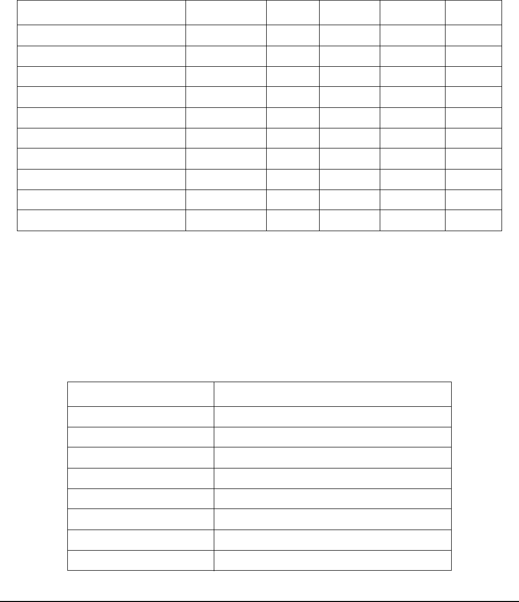
Chapter 5
Troubleshooting
Diagnostics
129
Online Support Tools List
The following online support tools are available on HP-UX 11.23 hosted servers. In some cases, a tool, such as
a disk exerciser, is generic to many types of hardware; in other cases, a tool, such as a tape diagnostic, is
specific to a particular technology or type of tape drive.
Offline Support Tool Availability
Updates to the EFI HP service partition (HPSP) are available through the CD Installer option on the IPF
Offline Diagnostics and Utilities CD. At a minimum, an ISO image of the IPF Offline Diagnostics and
Utilities CD is available from the HP website.
Offline Support Tools List
The following offline support tools are available:
Table 5-10 Online Support Tools List
Functional Area Information Verify Exercise Diagnose Expert
System Yes No No No No
CPU/FPU No No Yes No Yes
Memory Yes No Yes No No
Graph ics Yes Yes Ye s No N o
Core I/O LAN Yes Yes Yes Yes No
Disk /Arr ay s Yes Yes Ye s No N o
Tape Yes Yes Ye s Yes Yes
M/O Yes No No No Yes
Add-On Network I/O Cards Yes Yes Yes No Yes
Add-On Mass Storage I/O Cards Yes No No No No
Table 5-11 Offline Support Tools List
Offline Tool Functional Area
CPUDIAG Processor Diagnostic
MEMDIAG Memory Diagnostic
MAPPER System Mapping Utility
PLUTODIAG SBA/LBA Chipset
PERFVER Peripheral Verifier
DFDUTIL SCSI Disk Firmware Update Utility
DISKUTIL Disk Test Utility (Non-Destructive)
COPYUTIL Data Copy Utility
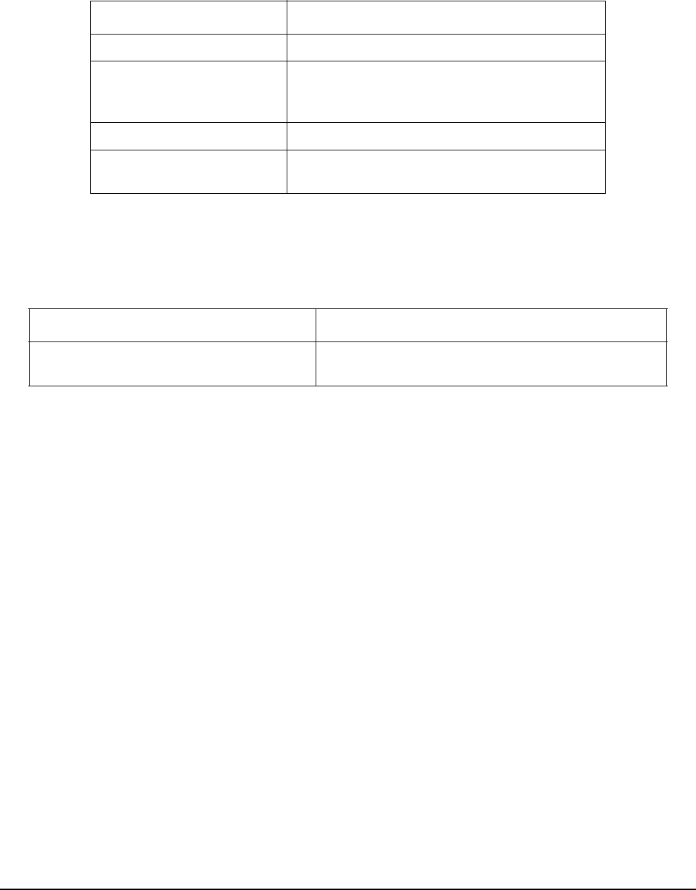
Chapter 5
Troubleshooting
Diagnostics
130
General Diagnostic Tools
The following tools are currently available for support on other HP 9000 and Integrity server platforms. The
distribution method is through the HP website.
Fault Management Overview
The goal of fault management and monitoring is to increase server availability, by moving from a reactive
fault detection, diagnosis, and repair strategy to a proactive fault detection, diagnosis, and repair strategy.
The objectives are:
• To detect problems automatically, as close as possible to the time of occurrence.
• To diagnose problems automatically, at the time of detection.
• To automatically report (in understandable text) a description of the problem, the likely cause(s) of the
problem, the recommended action(s) to resolve the problem, and detailed information about the problem.
• To ensure that tools are available to repair or recover from the fault.
HP-UX Fault Management
Proactive fault prediction and notification is provided on HP-UX by SysFaultMgmt WBEM indication
providers, as well as by the Event Management Service (EMS). The Event Management Service and WBEM
provide frameworks for monitoring and reporting events.
SysFaultMgmt WBEM indication providers and the EMS Hardware Monitors allow users to monitor the
operation of a wide variety of hardware products, and alert them immediately if any failure or other unusual
event occurs. By using hardware event monitoring, users can virtually eliminate undetected hardware
failures that could interrupt server operation or cause data loss.
Complete information on installing and using EMS hardware event monitors, as well as a list of supported
hardware, can be found in the EMS Hardware Monitors Users Guide. An electronic copy of this book is
available on the HP website at:
DISKEXPT Disk Expert Utility
IODIAG I/O Diagnostics Launch Facility (Executes
third party diagnostics and runs BIST, if
available)
CIODIAG2 Core I/O Diagnostic
Specific Card I/O
Diagnostics
Card-Specific I/O Diagnostics/BIST
Table 5-12 General Diagnostic Tools List
Diagnostic Tool Description
IPMI Event Decoder Provides detailed information about the IPMI event
(Problem description, cause, action)
Table 5-11 Offline Support Tools List (Continued)
Offline Tool Functional Area
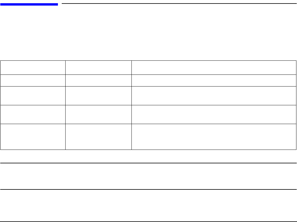
Chapter 5
Troubleshooting
Recommended Cleaning Procedures
131
http://docs.hp.com/hpux/diag.
WBEM indication providers and EMS Hardware Monitors
Hardware monitors are available to monitor the following components (these monitors are distributed free on
the OE media):
• Chassis/Fans/Environment
•CPU monitor
•UPS monitor
•FC Hub monitor
• FC Switch monitor
• Memory monitor
• Core Electronics Components
• Disk drives
• Ha_disk_array
Recommended Cleaning Procedures
Suggested cleaning procedures for the HP Integrity rx4640 server are provided in the following table. Be sure
to turn off power to the server when cleaning it. Table 5-13 details the components and procedures that need
cleaning for the server.
CAUTION DO NOT use petroleum-based cleaners (such as lighter fluid) or cleaners containing benzene,
trichlorethylene, ammonia, dilute ammonia, or acetone. These chemicals could damage all
plastic and painted surfaces.
Table 5-13 Cleaning
Component Time Frame Procedure
Keyboard Regularly Dust with damp, lint-free cloth.
Monitor screen Regularly Use “HP Video Screen Cleaning Solution” found in
92193M Master Clean Kit.
Mouse Regularly See the mouse manual for mouse maintenance
procedures.
Cooling fans and
grills
Six Months Check functions of cooling fans and clean the intake
openings on the chassis of dust, lint, and other
obstructions to airflow.

Chapter 5
Troubleshooting
Where to Get Help
132
Where to Get Help
HP customer care will help you solve server problems and, if necessary, initiate appropriate service
procedures.
Support is available on the HP website and by phone.
For information on contacting the HP IT Resource Center (ITRC) near you, go to: http://www.itrc.hp.com.
Information to Collect Before you Contact Support
Before you contact HP support, you should:
Step 1. Check the previous sections of this chapter and attempt to solve the problem.
• Note failure symptoms and error indications (LEDs and messages).
• Capture and permanently log the current SEL and FPL contents.
• Try to determine precisely what did or did not happen.
• Capture errdump logs
Step 2. Collect the following information:
• The model number of your server (for example rx4640).
• The product number of your server. This can be found on the identification label, which is found
on the pull-tab at the front of the server.
• The serial number of your server. This can be found on the identification label.
Step 3. Be familiar with your server configuration.
• Are you using the LAN, RS-232, or web interface to monitor the server?
• How many processors, DIMMs, and PCI cards have been installed?
• What versions of processor, memory, and PCI cards are used and where are they installed?
• What accessories are installed?
Step 4. Determine the following
• Which firmware versions are in use?
• When did the problem start?
• Have recent changes been made to the server?
• Which OS and version is in use?
Online Support
To contact HP Customer Support online, see the Worldwide Limited Warranty and Technical Support Guide
or visit us at:

Chapter 5
Troubleshooting
Where to Get Help
133
http://www.hp.com/go/bizsupport. On the web page, enter the server model number (rx4640) and search
the field.
The following information is available on this HP website:
• Software and firmware updates
• The latest drivers and utilities
• Additional documentation
Phone Support
To contact HP customer support by phone, go to the HP IT Resource Center (ITRC) near you, at:
http://www.itrc.hp.com. Local phone numbers are listed in your native language for help.

Chapter 5
Troubleshooting
Where to Get Help
134


Parts Information
Field Replaceable Parts List
Appendix A
136
Field Replaceable Parts List
The items in this list and the corresponding item numbers are the field replaceable units (FRUs) for the HP
Integrity rx4640 server.
NOTE Part numbers are found by using the part nomenclature from this list to select the correct part
from the HP Partsurfer. If a I/O baseboard needs to be replaced, remove processors, DIMMs,
and adapter boards and transfer these to the new board. Ensure all jumper and switch settings
on the old board are transferred to the new board.
Some part numbers shown in Table A-1 have two entries. The second entry is for the
Restriction of the Use of Certain Hazardous Substances (RoHS) compliant parts.
Table A-1 Parts List
Description Mfg. Part
Number
Part Number
Replacement
Part Number
Exchange
PCA Boards
PCA, Processor Extender A6961-60007 A6961-67007 A6961-69007
PCA, Processor Extender - (RoHS) A6961-60207 A6961-67207 A6961-69207
PCA, I/O baseboard (includes VRMs) A6961-60201 A6961-67401 A6961-69401
PCA, I/O baseboard (includes VRMs) - (RoHS) A6961-60401 A6961-67501 A6961-69501
PCA, I/O baseboard (includes VRMs) - (RoHS - dual core
processors only)
A6961-60401 A6961-67411 A6961-69511
PCA, 16 slot Memory Board A6961-60204 A6961-67204 A6961-69204
PCA, 16 slot Memory Board - (RoHS) A6961-60804 A6961-67804 A6961-69804
PCA, 32 slot Memory Board A7124-04006 A9739-67007 A9739-69007
PCA, 32 slot Memory Board - (RoHS) A7124-04008 A9739-67008 A9739-69008
PCA, Midplane Riser Board (Apian) A6961-60005 A6961-67005 n/a
PCA, Midplane Riser Board (Apian) - (RoHS) A6961-60105 A6961-67105 A6961-69105
PCA, SCSI Backplane/Management Assy, includes
Simplex board
A6961-04075 A6961-67024 n/a
PCA, SCSI Backplane/Management Assy, includes
Simplex board - (RoHS)
A6961-04076 A6961-67025 n/a
PCA, SCSI Duplex Board (HP-UX) A6961-60106 A6961-67106 n/a
PCA, SCSI Duplex Board (HP-UX) - (RoHS) A6961-60206 A6961-67206 n/a
PCA, Front Panel Display A6961-60008 A6961-67008 n/a
PCA, Front Panel Display - (RoHS) A6961-60108 A6961-67108 n/a

Parts Information
Field Replaceable Parts List
Appendix A 137
PCA, QuickFind Diagnostic Board (includes plastic cover
and label)
A6961-60009 A6961-67009 n/a
PCA, QuickFind Diagnostic Board (includes plastic cover
and label) - (RoHS)
A6961-60109 A6961-67109 n/a
PCA, Power Distribution Board A6961-60015 A6961-67015 n/a
PCA, Power Distribution Board - (RoHS) A6961-60115 A6961-67115 n/a
PCA, I/O Board to DVD connectivity (IDE/USB) A6961-60113 A6961-67113 n/a
PCA, I/O Board to DVD connectivity (IDE/USB) - (RoHS) A6961-60213 A6961-67213 n/a
Memory
256 MB DIMM A6967AX A6967AX n/a
512 MB DIMM A6968AX A6968AX n/a
1 GB DIMM A6969AX A6969AX A6969-69001
2 GB DIMM A6970AX A6970AX A6835-69001
4 GB DIMM AB475AX AD041A AB475-69001
Internal disks/removable media
36 GB 15K RPM SCSI Disk (A6981A) AB420-2101A AB420-2101A AB420-69001
73 GB 15K RPM SCSI Disk (A6983A) AB421-2101A AB421-2101A AB421-69001
146 GB 10K RPM SCSI Disk (A6984A) AB422-2101A AB422-2101A AB422-69001
300 GB 10K RPM SCSI Disk (A6984A) AB423-2101A AB423-2101A AB423-69001
DVD-R/CD-R Drive A7163-2100A A7163-67002 n/a
DVD-R/CD-RW Drive AB349-2100A AB349-67101 n/a
Fans
I/O Fan A6961-04055 A6961-04055 n/a
Power Supply Fan A6961-04028 A6961-04028 n/a
Processors
Montecito CPU Assembly (1.6 GHz), 18 Mb cache AD139AX AD139A-67001 AD139-69001
Montecito CPU Assembly (1.6 GHz), 24 Mb cache AD268AX AD268A-67001 AD268-69001
Cable
Cable, Internal SCSI A6961-63006 A6961-63006 n/a
Cable, QuickFind Diagnostic to Midplane A6961-63005 A6961-63005 n/a
Table A-1 Parts List (Continued)
Description Mfg. Part
Number
Part Number
Replacement
Part Number
Exchange

Parts Information
Field Replaceable Parts List
Appendix A
138
Cable, Power Distribution to Midplane Ribbon A6961-63004 A6961-63004 n/a
Cable, Power Distribution to Midplane 10 pin A6961-63003 A6961-63003 n/a
Cable, SCSI Controller Jumper (Simplex only) A6961-63011 A6961-63011 n/a
Cable, SCSI Backplane to Midplane A6961-63008 A6961-63008 n/a
Cable, Display to IDE to Midplane A6961-63002 A6961-63002 n/a
Power Cord - S. Africa 8120-5341 n/a
Power Cord - HK & UK & Singapore 8120-1351 n/a
Power Cord - Australia 8120-1369 n/a
Power Cord - Europe 8120-1689 n/a
Power Cord - Swiss 8120-2104 n/a
Power Cord - Denmark 8120-6814 n/a
Power Cord - N. Amer 250 V / Japan 8121-0875 n/a
Power Cord - Israel 8120-6800 n/a
Power Cord - Argentina 8120-8390 n/a
Power Cord - Chile 8120-8389 n/a
Power Cord - China 8120-8376 n/a
Power Cord - S. America 8121-0668 n/a
Power Cord 8120-1351 8120-1351
C13/C14 Jumper cord 8120-6514 n/a
Miscellaneous
Power Supply 0950-4428 A6961-67125 n/a
PCI Card OL* Divider (doorbell and latch included) A6961-04047 A6961-67020 n/a
PCI Retention Clip A6961-40021 A6961-67021 n/a
Server battery 1420-0386 BR2330 n/a
Filler, Memory, Air Blocker A6961-40034 A6961-40034 n/a
Rack solutions
Rack Mount Hardware, Right (included with Left Bracket
in kit)
5069-3305 A6977-67001 n/a
Rack Mount Hardware, Left (included with Right Bracket
in kit)
5069-3306 A6977-67002 n/a
Table A-1 Parts List (Continued)
Description Mfg. Part
Number
Part Number
Replacement
Part Number
Exchange

Parts Information
Field Replaceable Parts List
Appendix A 139
Bezel-Rack Mount A6961-04043 A6977-67022 n/a
Rackless Kit A6961-04001 n/a n/a
Core I/O Cards
U320 Dual Port SCSI Core I/O A6961-60011 A6961-67011 n/a
Dual Port GigE LAN Card AB352-60001 AB352-67001 n/a
PCI-X RAID Smart Array 6402 U320, 2ch 322391-001 309520-001N 309520-001
SPS-BD, Mem, 128, 72Bt, DDR, W.Bty (mounted on PCA
for Prod # A9890A)
322391-001 309521-001N 309521-001
Monitor/Keyboard/Mouse
18.1” LCD Flat panel Display (Prod # P9021Y) 303486-003 303486-003
20” LCD Flat panel Display (Prod # P4831Y) 303102-003 303102-003
19” CRT Color Monitor (Prod # P9009A) 302268-003 302268-003
21” CRT Color Monitor (Prod # P4819A) 302270-003 302270-003
24” CRT Color Monitor (Prod # P7217A) A7217-60001 A7217-60001
Serial Console (Prod # C1099A) C1099-62000 C1099-67001
Serial Console ROM Replacement Kit (Prod # C1099A) C1099-62000 C1099-67002
USB Keyboard and Mouse (Prod # A7861A) Depends on product options
USB to PS/2 Adapter (Prod # A7782A) A7782-63001 A7782-63001
Table A-1 Parts List (Continued)
Description Mfg. Part
Number
Part Number
Replacement
Part Number
Exchange

Parts Information
Field Replaceable Parts List
Appendix A
140

Appendix B 141
BBooting the Operating System
This chapter covers procedures for booting and shutting down an operating system on the HP Integrity
rx4640 server. The following operating systems are supported on HP Integrity servers: HP-UX 11i Version 2
(B.11.23), HP OpenVMS, Microsoft Windows Server 2003, Red Hat Enterprise Linux, and SuSE Linux
Enterprise Server.
This chapter addresses the following topics:
• “Operating Systems Supported on HP Integrity Servers” on page 142.
• “Configuring System Boot Options” on page 142.
• “Booting and Shutting Down HP-UX” on page 143.
• “Booting and Shutting Down HP OpenVMS” on page 149.
• “Booting and Shutting Down Microsoft Windows” on page 153.
• “Booting and Shutting Down Linux” on page 157.

Booting the Operating System
Operating Systems Supported on HP Integrity Servers
Appendix B
142
Operating Systems Supported on HP Integrity Servers
HP supports the following operating systems on entry-class HP Integrity servers.
•HP-UX 11i Version 2 (B.11.23)
For details see “Booting and Shutting Down HP-UX” on page 143.
•HP OpenVMS I64
For details see “Booting and Shutting Down HP OpenVMS” on page 149.
•Microsoft® Windows® Server 2003
For details see “Booting and Shutting Down Microsoft Windows” on page 153.
•Red Hat Enterprise Linux 4
For details see “Booting and Shutting Down Linux” on page 157.
•SuSE Linux Enterprise Server 10
For details see “Booting and Shutting Down Linux” on page 157.
Configuring System Boot Options
This section discusses the system boot options you can configure on entry-class HP Integrity servers,
including the boot options list and the autoboot setting for the server.
•Boot Options List
The boot options list is a list of loadable items available for you to choose from the EFI Boot Manager
menu. Ordinarily the boot options list includes the EFI Shell and one or more operating system loaders.
The following example includes boot options for HP OpenVMS, Microsoft Windows, HP-UX, and the EFI
Shell. The final item in the EFI Boot Manager menu, the Boot Configuration menu, is not a boot option.
The Boot Configuration menu allows server configuration through a maintenance menu.
EFI Boot Manager ver 1.10 [14.61] Please select a boot option
HP OpenVMS 8.2-1
EFI Shell [Built-in]
Windows Server 2003, Enterprise
HP-UX Primary Boot: 4/0/1/1/0.2.0
Boot Option Maintenance Menu
Use ^ and v to change option(s). Use Enter to select an option
NOTE In some versions of EFI, the Boot Configuration Menu is listed as the Boot Option Maintenance
Menu.
To manage the boot options list for each server, use the EFI Shell, the EFI Boot Configuration Menu, or
operating system utilities.

Booting the Operating System
Booting and Shutting Down HP-UX
Appendix B 143
At the EFI Shell, the bcfg command supports listing and managing the boot options list for all operating
systems, except Microsoft Windows. On HP Integrity servers with Windows installed, the
\MSUtil\nvrboot.efi utility is provided for managing Windows boot options from the EFI Shell. For HP
Integrity servers with OpenVMS installed, the \efi\vms\vms_bcfg.efi and \efi\vms\vms_show
utilities are provided for managing OpenVMS boot options.
The EFI Boot Configuration Menu provides the Add a Boot Option, Delete Boot Option(s), and Change Boot
Order menu items (use this method if you must add an EFI Shell entry to the boot options list).
Operating system utilities for managing the boot options list include the HP-UX setboot command and
the HP OpenVMS @SYS$MANAGER:BOOT_OPTIONS.COM command.
For details, see the following sections:
— Setting HP-UX boot options (see “Adding HP-UX to the Boot Options List” on page 144)
— Setting OpenVMS boot options (see “Adding HP OpenVMS to the Boot Options List” on page 149)
— Setting Windows boot options (see “Adding Microsoft Windows to the Boot Options List” on page 153)
— Setting Linux boot options (see “Adding Linux to the Boot Options List” on page 157)
•Autoboot Setting
The autoboot setting determines, at startup, whether a server automatically loads the first item in the
boot options list, or remains at the EFI Boot Manager menu. When autoboot is enabled, EFI loads the
first item in the boot options list after a designated timeout period.
Configure the autoboot setting for an HP Integrity server using either the autoboot EFI Shell command,
or the Set Auto Boot TimeOut menu item from the EFI Boot Configuration menu.
For example, from the EFI Shell to disable autoboot issue the autoboot off command. To enable
autoboot with the default timeout value issue the autoboot on command. To enable autoboot with a
timeout of 60 seconds issue the autoboot time 60 command.
Set autoboot from HP-UX using the setboot command. Enable autoboot from HP-UX using the setboot
-b on command. Disable autoboot using the setboot -b off command.
Booting and Shutting Down HP-UX
This section covers booting and shutting down HP-UX on entry-class HP Integrity servers.
• To add an HP-UX entry to the boot options list, see “Adding HP-UX to the Boot Options List”.
• To boot HP-UX, use the following procedures:
— “Standard HP-UX Booting” on page 145 describes the standard ways to boot HP-UX. Typically this
results in booting HP-UX in multi-user mode.
— “Single-User Mode HP-UX Booting” on page 146 describes how to boot HP-UX in single-user mode.
— “LVM Maintenance Mode HP-UX Booting” on page 148 describes how to boot HP-UX in Logical
Volume Management (LVM) maintenance mode.
• To shut down the HP-UX operating system, see “Shutting Down HP-UX” on page 148.

Booting the Operating System
Booting and Shutting Down HP-UX
Appendix B
144
Adding HP-UX to the Boot Options List
This section describes how to add an HP-UX entry to the system boot options list.
You can add the \EFI\HPUX\HPUX.EFI loader to the boot options list from the EFI Shell or EFI Boot
Configuration menu (or in some versions of EFI, the Boot Option Maintenance Menu).
NOTE On HP Integrity servers, the operating system installer automatically adds an entry to the boot
options list.
Adding an HP-UX Boot Option
This procedure adds an HP-UX item to the boot options list from the EFI Shell.
To add an HP-UX boot option when logged in to HP-UX, use the setboot command. For details see
the setboot (1M) manpage.
Step 1. Access the EFI Shell environment.
Log in to the iLO MP and enter CO to access the server console.
When accessing the console, confirm that you are at the EFI Boot Manager menu (the main EFI
menu). If you are at another EFI menu, choose the Exit option from the submenus until you return
to the screen with the EFI Boot Manager heading.
From the EFI Boot Manager menu, choose the EFI Shell menu option to access the EFI Shell
environment.
Step 2. Access the EFI System Partition (fs
X
: where
X
is the file system number) for the device from which
you want to boot HP-UX.
For example, enter fs2: to access the EFI System Partition for the bootable file system number 2.
The EFI Shell prompt changes to reflect the file system currently accessed.
The full path for the HP-UX loader is \EFI\HPUX\HPUX.EFI and it should be on the device you are
accessing.
Step 3. At the EFI Shell environment, use the bcfg command to manage the boot options list.
The bcfg command includes the following options for managing the boot options list:
•bcfg boot dump — Display all items in the boot options list for the server.
•bcfg boot rm
#
— Remove the item number specified by
#
from the boot options list.
•bcfg boot mv
#a
#b
— Move the item number specified by
#a
to the position specified by
#b
in the boot options list.
•bcfg boot add
#
file.efi
"
Description
" — Add a new boot option to the position in the
boot options list specified by
#
. The new boot option references
file.efi
and is listed with the
title specified by
Description
.
For example, bcfg boot add 1 \EFI\HPUX\HPUX.EFI "HP-UX 11i" adds an HP-UX 11i item
as the first entry in the boot options list.
See the help bcfg command for details.
Step 4. Exit the console and iLO MP interfaces if you are finished using them.

Booting the Operating System
Booting and Shutting Down HP-UX
Appendix B 145
Press Ctrl+B to exit the system console and return to the iLO MP Main Menu. To exit the iLO MP,
enter X at the Main Menu.
Standard HP-UX Booting
Use either of the following procedures to boot HP-UX:
• “Access the EFI Boot Manager menu for the server on which you want to boot HP-UX.” on page 145
• “Access the EFI Shell environment for the server on which you want to boot HP-UX.” on page 145
Booting HP-UX (EFI Boot Manager)
From the EFI Boot Manager menu, choose an item from the boot options list to boot HP-UX.
Step 1. Access the EFI Boot Manager menu for the server on which you want to boot HP-UX.
Log in to the iLO MP and enter CO to choose the system console.
When accessing the console, confirm that you are at the EFI Boot Manager menu (the main EFI
menu). If you are at another EFI menu, choose the Exit option from the submenus until you return
to the screen with the EFI Boot Manager heading.
Step 2. At the EFI Boot Manager menu, choose an item from the boot options list.
Each item in the boot options list references a specific boot device and provides a specific set of boot
options or arguments you use when booting the device.
Step 3. Press Enter to initiate booting using the chosen boot option.
Step 4. Exit the console and iLO MP interfaces when finished using them.
Press Ctrl+B to exit the system console and return to the iLO MP Main Menu. To exit the iLO MP,
enter X at the Main Menu.
Booting HP-UX (EFI Shell)
From the EFI Shell environment, boot HP-UX on a device by first accessing the EFI System Partition (for
example fs0:) for the root device, then entering HPUX to initiate the loader.
Step 1. Access the EFI Shell environment for the server on which you want to boot HP-UX.
Log in to the iLO MP and enter CO to choose the system console.
When accessing the console, confirm that you are at the EFI Boot Manager menu (the main EFI
menu). If you are at another EFI menu, choose the Exit option from the submenus until you return
to the screen with the EFI Boot Manager heading.
From the EFI Boot Manager menu, choose the EFI Shell menu option to access the EFI Shell
environment.
Step 2. At the EFI Shell environment, issue the map command to list all currently mapped bootable devices.
The bootable file systems of interest typically are listed as fs0:, fs1:, and so on.
Step 3. Access the EFI System Partition (fs
X
: where
X
is the file system number) for the device from which
you want to boot HP-UX.
For example, enter fs2: to access the EFI System Partition for the bootable file system number 2.
The EFI Shell prompt changes to reflect the file system currently accessed.

Booting the Operating System
Booting and Shutting Down HP-UX
Appendix B
146
The file system number might change each time it is mapped (for example, when the system boots,
or when the map -r command is issued).
Step 4. When accessing the EFI System Partition for the desired boot device, issue the HPUX command to
initiate the HPUX.EFI loader on the device you are accessing.
The full path for the loader is \EFI\HPUX\HPUX.EFI. When initiated, the loader references the
\EFI\HPUX\AUTO file and proceeds to boot HP-UX using the default boot behavior specified in the
AUTO file.
You have 10 seconds to interrupt the automatic booting of the default boot behavior. Pressing any
key during this 10-second period stops the HP-UX boot process and enables you to interact with the
HPUX.EFI loader. To exit the loader (the HPUX> prompt) enter exit (this returns you to the EFI
Shell).
To boot the HP-UX operating system, do not enter anything during the 10-second period given for
stopping at the HPUX.EFI loader.
Shell> map
Device mapping table
fs0 : Acpi(000222F0,269)/Pci(0|0)/Scsi(Pun8,Lun0)/HD(Part1,Sig72550000)
blk0 : Acpi(000222F0,269)/Pci(0|0)/Scsi(Pun8,Lun0)
blk1 : Acpi(000222F0,269)/Pci(0|0)/Scsi(Pun8,Lun0)/HD(Part1,Sig72550000)
blk2 : Acpi(000222F0,269)/Pci(0|0)/Scsi(Pun8,Lun0)/HD(Part2,Sig72550000)
blk3 : Acpi(000222F0,2A8)/Pci(0|0)/Scsi(Pun8,Lun0)
blk4 : Acpi(000222F0,2A8)/Pci(0|1)/Scsi(Pun2,Lun0)
Shell> fs0:
fs0:\> hpux
(c) Copyright 1990-2002, Hewlett Packard Company.
All rights reserved
HP-UX Boot Loader for IA64 Revision 1.723
Press Any Key to interrupt Autoboot
\efi\hpux\AUTO ==> boot vmunix
Seconds left till autoboot - 9
Step 5. Exit the console and iLO MP interfaces when finished using them.
Press Ctrl+B to exit the system console and return to the iLO MP Main Menu. To exit the iLO MP,
enter X at the Main Menu.
Single-User Mode HP-UX Booting
Use the following procedure to boot HP-UX in single-user mode.
Booting HP-UX in Single-User Mode (EFI Shell)
From the EFI Shell environment, boot in single-user mode by stopping the boot process at the HPUX.EFI
interface (the HP-UX Boot Loader prompt, HPUX>) and entering the boot -is vmunix command.
Step 1. Access the EFI Shell environment for the system on which you want to boot HP-UX in single-user
mode.
Log in to the iLO MP and enter CO to choose the system console.

Booting the Operating System
Booting and Shutting Down HP-UX
Appendix B 147
When accessing the console, confirm that you are at the EFI Boot Manager menu (the main EFI
menu). If you are at another EFI menu, choose the Exit option from the submenus until you return
to the screen with the EFI Boot Manager heading.
From the EFI Boot Manager menu, choose the EFI Shell menu option to access the EFI Shell
environment.
Step 2. Access the EFI System Partition (fs
X
: where
X
is the file system number) for the device from which
you want to boot HP-UX.
Step 3. When accessing the EFI System Partition for the desired boot device, issue the HPUX command to
initiate the \EFI\HPUX\HPUX.EFI loader on the device you are accessing.
Step 4. Boot to the HP-UX Boot Loader prompt (HPUX>) by pressing any key within the 10 seconds given for
interrupting the HP-UX boot process. Use the HPUX.EFI loader to boot HP-UX in single-user mode
in the next step.
After you press a key, the HPUX.EFI interface (the HP-UX Boot Loader prompt, HPUX>) launches.
For help using the HPUX.EFI loader, enter the help command. To return to the EFI Shell, enter
exit.
fs0:\> hpux
(c) Copyright 1990-2002, Hewlett Packard Company.
All rights reserved
HP-UX Boot Loader for IA64 Revision 1.723
Press Any Key to interrupt Autoboot
\efi\hpux\AUTO ==> boot vmunix
Seconds left till autoboot - 9
[User Types A Key to Stop the HP-UX Boot Process and Access the HPUX.EFI Loader ]
Type ’help’ for help
HPUX>
Step 5. At the HPUX.EFI interface (the HP-UX Boot Loader prompt, HPUX>) enter the boot -is vmunix
command to boot HP-UX (the /stand/vmunix kernel) in single-user (-is) mode.
HPUX> boot -is vmunix
> System Memory = 4063 MB
loading section 0
................................................... (complete)
loading section 1
........ (complete)
loading symbol table
loading System Directory(boot.sys) to MFS
....
loading MFSFILES Directory(bootfs) to MFS
......
Launching /stand/vmunix
SIZE: Text:25953K + Data:3715K + BSS:3637K = Total:33306K
Console is on a Serial Device
Booting kernel...
Step 6. Exit the console and iLO MP interfaces when finished using them.
Press Ctrl+B to exit the system console and return to the iLO MP Main Menu. To exit the iLO MP,
enter X at the Main Menu.

Booting the Operating System
Booting and Shutting Down HP-UX
Appendix B
148
LVM Maintenance Mode HP-UX Booting
Use the following procedure to boot HP-UX in Logical Volume Management (LVM) maintenance mode.
Booting HP-UX in LVM-Maintenance Mode (EFI Shell)
From the EFI Shell environment, boot in LVM-maintenance mode by stopping the boot process at the
HPUX.EFI interface (the HP-UX Boot Loader prompt, HPUX>) and entering the boot -lm vmunix command.
Step 1. Access the EFI Shell environment for the server on which you want to boot HP-UX in
LVM-maintenance mode.
Log in to the iLO MP and enter CO to choose the system console.
When accessing the console, confirm that you are at the EFI Boot Manager menu (the main EFI
menu). If you are at another EFI menu, choose the Exit option from the submenus until you return
to the screen with the EFI Boot Manager heading.
From the EFI Boot Manager menu, choose the EFI Shell menu option to access the EFI Shell
environment.
Step 2. Access the EFI System Partition (fs
X
: where
X
is the file system number) for the device from which
you want to boot HP-UX.
Step 3. When accessing the EFI System Partition for the desired boot device, issue the HPUX command to
initiate the \EFI\HPUX\HPUX.EFI loader on the device you are accessing.
Step 4. Press any key within the 10 seconds given for interrupting the HP-UX boot process. This stops the
boot process at the HPUX.EFI interface (the HP-UX Boot Loader prompt, HPUX>).
Step 5. At the HPUX.EFI interface, enter the boot -lm vmunix command to boot HP-UX (the
/stand/vmunix kernel) in LVM-maintenance (-lm) mode.
Step 6. Exit the console and iLO MP interfaces when finished using them.
Press Ctrl+B to exit the system console and return to the iLO MP Main Menu. To exit the iLO MP,
enter X at the Main Menu.
Shutting Down HP-UX
To shut down HP-UX running on a server, use the shutdown command. You have the following options when
shutting down HP-UX:
• To shut down and reboot an HP-UX server, use the shutdown -r command.
• To shut down and halt (power off) an HP-UX server, use the shutdown -h command.
For details see the shutdown (1M) manpage and the following procedure:
Shutting Down HP-UX (/sbin/shutdown Command)
From the HP-UX command line, issue the shutdown command to shut down the HP-UX operating system.
Step 1. Log in to HP-UX running on the server that you want to shut down.
You should log in to the iLO MP for the server and use the Console menu to access the system
console. Accessing the console through the iLO MP enables you to maintain console access to the
server after HP-UX has shut down.
Step 2. Issue the shutdown command with the appropriate command-line options.

Booting the Operating System
Booting and Shutting Down HP OpenVMS
Appendix B 149
The command-line options you specify dictate the way in which HP-UX shuts down, and whether
the server is rebooted.
Use the following list to choose an HP-UX shutdown option for your server:
• To shut down HP-UX and halt (power off) the server, issue the shutdown -h command.
To reboot a halted server you must power on the server using the PC command at the iLO MP
Command menu.
• To shut down HP-UX and reboot the server, issue the shutdown -r command.
Booting and Shutting Down HP OpenVMS
This section has procedures for booting and shutting down HP OpenVMS on entry-class HP Integrity servers,
and procedures for adding HP OpenVMS to the boot options list.
• To add an HP OpenVMS entry to the boot options list, see “Adding HP OpenVMS to the Boot Options
List” on page 149.
• To boot HP OpenVMS on an entry-class HP Integrity server, see “Booting HP OpenVMS” on page 150.
• To shut down HP OpenVMS, see “Shutting Down HP OpenVMS” on page 152.
Adding HP OpenVMS to the Boot Options List
On HP Integrity servers, you can use the following procedures to manage boot options list entries for HP
OpenVMS.
You can add the \efi\vms\vms_loader.efi loader to the boot options list from the EFI Shell or EFI Boot
Configuration menu (or in some versions of EFI, the Boot Option Maintenance Menu).
NOTE On HP Integrity servers, the operating system installer automatically adds an entry to the boot
options list.
Adding an HP OpenVMS Boot Option
This procedure adds an HP OpenVMS item to the boot options list from the EFI Shell.
To add an HP OpenVMS boot option when logged in to OpenVMS, use the
@SYS$MANAGER:BOOT_OPTIONS.COM command.
Step 1. Access the EFI Shell environment.
Log in to the iLO MP and enter CO to access the system console.
When accessing the console, confirm that you are at the EFI Boot Manager menu (the main EFI
menu). If you are at another EFI menu, choose the Exit option from the submenus until you return
to the screen with the EFI Boot Manager heading.
From the EFI Boot Manager menu, choose the EFI Shell menu option to access the EFI Shell
environment.

Booting the Operating System
Booting and Shutting Down HP OpenVMS
Appendix B
150
Step 2. Access the EFI System Partition (fs
X
: where
X
is the file system number) for the device from which
you want to boot HP OpenVMS.
For example, enter fs2: to access the EFI System Partition for the bootable file system number 2.
The EFI Shell prompt changes to reflect the file system currently accessed.
The full path for the HP OpenVMS loader is \efi\vms\vms_loader.efi and it should be on the
device you are accessing.
Step 3. At the EFI Shell environment, use the bcfg command to manage the boot options list.
You can also accomplish this step by using the \efi\vms\vms_bcfg.efi and
\efi\vms\vms_show.efi utilities, which are available on the EFI System Partition for HP
OpenVMS. Both vms_bcfg and vms_show are unique utilities for OpenVMS I64. The vms_bcfg
utility differs from the bcfg EFI command in that vms_bcfg enables you to specify boot devices
using VMS-style device names.
The bcfg command includes the following options for managing the boot options list:
•bcfg boot dump — Displays all items in the boot options list for the server.
•bcfg boot rm
#
— Removes the item number specified by
#
from the boot options list.
•bcfg boot mv
#a
#b
— Moves the item number specified by
#a
to the position specified by
#b
in the boot options list.
•bcfg boot add
#
file.efi
"
Description
" — Adds a new boot option to the position in the
boot options list specified by
#
. The new boot option references
file.efi
and is listed with the
title specified by
Description
.
For example, bcfg boot add 1 \efi\vms\vms_loader.efi "HP OpenVMS" adds an HP
OpenVMS item as the first entry in the boot options list.
See the help bcfg command for details.
Step 4. Exit the console and iLO MP interfaces if you are finished using them.
Press Ctrl+B to exit the system console and return to the iLO MP Main Menu. To exit the iLO MP,
enter X at the Main Menu.
Booting HP OpenVMS
To boot HP OpenVMS on an entry-class HP Integrity server, use either of the following procedures:
• “Booting HP OpenVMS (EFI Boot Manager)” on page 150
• “Booting HP OpenVMS (EFI Shell)” on page 151
Booting HP OpenVMS (EFI Boot Manager)
From the EFI Boot Manager menu, choose an item from the boot options list to boot HP OpenVMS
using the chosen boot option.
Step 1. Access the EFI Boot Manager menu for the server on which you want to boot HP OpenVMS.
Log in to the iLO MP and enter CO to choose the system console.
When accessing the console, confirm that you are at the EFI Boot Manager menu (the main EFI
menu). If you are at another EFI menu, choose the Exit option from the submenus until you return
to the screen with the EFI Boot Manager heading.

Booting the Operating System
Booting and Shutting Down HP OpenVMS
Appendix B 151
Step 2. At the EFI Boot Manager menu, choose an item from the boot options list.
Each item in the boot options list references a specific boot device and provides a specific set of boot
options or arguments to use when booting the device.
Step 3. Press Enter to initiate booting using the chosen boot option.
Step 4. Exit the console and iLO MP interfaces when finished using them.
Press Ctrl+B to exit the system console and return to the iLO MP Main Menu. To exit the iLO MP,
enter X at the Main Menu.
Booting HP OpenVMS (EFI Shell)
From the EFI Shell environment, to boot HP OpenVMS on a device first access the EFI System
Partition (for example fs0:) for the root device and enter \efi\vms\vms_loader to initiate the
OpenVMS loader.
Step 1. Access the EFI Shell environment for the server on which you want to boot HP OpenVMS.
Log in to the iLO MP and enter CO to choose the system console.
When accessing the console, confirm that you are at the EFI Boot Manager menu (the main EFI
menu). If you are at another EFI menu, choose the Exit option from the submenus until you return
to the screen with the EFI Boot Manager heading.
From the EFI Boot Manager menu, choose the EFI Shell menu option to access the EFI Shell
environment.
Step 2. At the EFI Shell environment, issue the map command to list all currently mapped bootable devices.
The bootable file systems of interest typically are listed as fs0:, fs1:, and so on.
Step 3. Access the EFI System Partition (fs
X
: where
X
is the file system number) for the device from which
you want to boot HP OpenVMS.
For example, enter fs2: to access the EFI System Partition for the bootable file system number 2.
The EFI Shell prompt changes to reflect the file system currently accessed.
Also, the file system number might change each time it is mapped (for example, when the server
boots, or when the map -r command is issued).
Step 4. When accessing the EFI System Partition for the desired boot device, issue the
\efi\vms\vms_loader command to initiate the vms_loader.efi loader on the device you are
accessing.
fs5:> \efi\vms\vms_loader.efi
HP OpenVMS Industry Standard 64 Operating System, Version XAV1-D2Y
Copyright 1976-2005 Hewlett-Packard Development Company, L.P.
%PKA0, Copyright (c) 1998 LSI Logic PKW V3.2.20 ROM 4.19
%PKA0, SCSI Chip is SYM53C1010/66, Operating mode is LVD Ultra3 SCSI
%SMP-I-CPUTRN, CPU #01 has joined the active set.
%SMP-I-CPUTRN, CPU #02 has joined the active set.
%STDRV-I-STARTUP, OpenVMS startup begun at 13-JUL-2005 14:54:36.25
%EWA0, Auto-negotiation mode set by console
...
Step 5. Exit the console and iLO MP interfaces when finished using them.

Booting the Operating System
Booting and Shutting Down HP OpenVMS
Appendix B
152
Press Ctrl+B to exit the system console and return to the iLO MP Main Menu. To exit the iLO MP,
enter X at the Main Menu.
Shutting Down HP OpenVMS
This section describes how to shut down the HP OpenVMS operating system on entry-class HP Integrity
servers.
Step 1. From the HP OpenVMS DCL prompt, issue the @SYS$SYSTEM:SHUTDOWN command to shut down
the OpenVMS operating system.
Step 2. Log in to HP OpenVMS running on the server that you want to shut down.
You should log in to the iLO MP for the server and use the Console menu to access the system
console. Accessing the console through the iLO MP enables you to maintain console access to the
server after HP OpenVMS has shut down.
Step 3. At the OpenVMS DCL prompt issue the @SYS$SYSTEM:SHUTDOWN command and specify the
shutdown options in response to the prompts given.
>@SYS$SYSTEM:SHUTDOWN
SHUTDOWN -- Perform an Orderly System Shutdown
on node RSNVMS
How many minutes until final shutdown [0]:
Reason for shutdown [Standalone]:
Do you want to spin down the disk volumes [NO]?
Do you want to invoke the site-specific shutdown procedure [YES]?
Should an automatic system reboot be performed [NO]? yes
When will the system be rebooted [shortly via automatic reboot]:
Shutdown options (enter as a comma-separated list):
REBOOT_CHECK Check existence of basic system files
SAVE_FEEDBACK Save AUTOGEN feedback information from this boot
DISABLE_AUTOSTART Disable autostart queues
POWER_OFF Request console to power-off the system
Shutdown options [NONE]:
%SHUTDOWN-I-OPERATOR, this terminal is now an operator’s console
%%%%%%%%%%% OPCOM 12-JUL-2005 18:47:51.01 %%%%%%%%%%%
Operator status for operator _RSNVMS$OPA0:
CENTRAL, PRINTER, TAPES, DISKS, DEVICES, CARDS, NETWORK, CLUSTER, SECURITY,
...
NOTE HP OpenVMS I64 currently does not support the POWER_OFF shutdown option.

Booting the Operating System
Booting and Shutting Down Microsoft Windows
Appendix B 153
Booting and Shutting Down Microsoft Windows
This section describes how to boot and shut down Microsoft Windows on entry-class HP Integrity servers and
how to add Windows entries to the system boot options list.
• “Adding Microsoft Windows to the Boot Options List” on page 153
• “Booting the Microsoft Windows Operating System” on page 154
• “Shutting Down Microsoft Windows” on page 155
Adding Microsoft Windows to the Boot Options List
To add a Microsoft Windows entry to the system boot options list you must do so from EFI by using the
\MSUtil\nvrboot.efi utility to import boot options from the EFI\Microsoft\WINNT50\Boot00... file on
the device from which Windows is loaded.
This procedure adds the Microsoft Windows item to the boot options list.
NOTE On HP Integrity servers, the operating system installer automatically adds an entry to the boot
options list.
Step 1. Access the EFI Shell environment.
Log in to the iLO MP and enter CO to access the system console.
When accessing the console, confirm that you are at the EFI Boot Manager menu (the main EFI
menu). If you are at another EFI menu, choose the Exit option from the submenus until you return
to the screen with the EFI Boot Manager heading.
From the EFI Boot Manager menu, choose the EFI Shell menu option to access the EFI Shell
environment.
Step 2. Access the EFI System Partition (fs
X
: where
X
is the file system number) for the device from
which you want to boot Windows.
For example, enter fs2: to access the EFI System Partition for the bootable file system number 2.
The EFI Shell prompt changes to reflect the file system currently accessed.
The full path for the Microsoft Windows loader is \efi\microsoft\winnt50\ia64ldr.efi and it
should be on the device you are accessing. However, you must only initiate this loader from the EFI
Boot Menu and not from the EFI Shell.
Step 3. List the contents of the \EFI\Microsoft\WINNT50 directory to identify the name of the Windows
boot option file (Boot00nn) that you want to import into the system boot options list.
fs0:\> ls EFI\Microsoft\WINNT50
Directory of: fs0:\EFI\Microsoft\WINNT50
09/18/03 11:58a <DIR> 1,024 .
09/18/03 11:58a <DIR> 1,024 ..
12/18/03 08:16a 354 Boot0001
1 File(s) 354 bytes
2 Dir(s)
fs0:\>

Booting the Operating System
Booting and Shutting Down Microsoft Windows
Appendix B
154
Step 4. At the EFI Shell environment, issue the \MSUtil\nvrboot.efi command to launch the Microsoft
Windows boot options utility.
fs0:\> msutil\nvrboot
NVRBOOT: OS Boot Options Maintenance Tool [Version 5.2.3683]
1. SUSE SLES 10
2. HP-UX Primary Boot: 0/0/1/0/0.2.0
* 3. Windows Server 2003, Datacenter
4. EFI Shell [Built-in]
* = Windows OS boot option
(D)isplay (M)odify (C)opy E(x)port (I)mport (E)rase (P)ush (H)elp (Q)uit
Select>
Step 5. Use the Import command to import the Window boot option file.
Select> i
Enter IMPORT file path: \EFI\Microsoft\WINNT50\Boot0001
Imported Boot Options from file: \EFI\Microsoft\WINNT50\Boot0001
Press enter to continue
Step 6. Enter Q to quit the NVRBOOT utility, and exit the console and management processor interfaces if
you are finished using them.
Press Ctrl+B to exit the system console and return to the iLO MP Main Menu. To exit the iLO MP,
enter X at the Main Menu.
Booting the Microsoft Windows Operating System
Boot the Windows Server 2003 operating system on an HP Integrity server by using the EFI Boot Manager to
choose the appropriate Windows item from the boot options list. See “Shutting Down Microsoft Windows” on
page 155 for details on shutting down the Windows operating system.
Step 1. From the EFI Boot Manager menu, choose an item from the boot options list to boot Windows using
the chosen boot option.
Step 2. Access the EFI Boot Manager menu for the server on which you want to boot Windows.
Log in to the management processor and enter CO to choose the system console.
When accessing the console, confirm that you are at the EFI Boot Manager menu (the main EFI
menu). If you are at another EFI menu, choose the Exit option from the submenus until you return
to the screen with the EFI Boot Manager heading.
Step 3. At the EFI Boot Manager menu, choose an item from the boot options list.
Each item in the boot options list references a specific boot device and provides a specific set of boot
options or arguments to be used when booting the device.
Step 4. Press Enter to initiate booting using the chosen boot option.
Step 5. Once Windows begins loading, wait for the Special Administration Console (SAC) to become
available.
The SAC interface provides a text-based administration tool that is available from the system
console. For details see the SAC online help (enter ? at the SAC> prompt).

Booting the Operating System
Booting and Shutting Down Microsoft Windows
Appendix B 155
Loading.: Windows Server 2003, Datacenter
Starting: Windows Server 2003, Datacenter
Starting Windows...
********************************************************************************
Computer is booting, SAC started and initialized.
Use the "ch -?" command for information about using channels.
Use the "?" command for general help.
SAC>
Step 6. Exit the console and management processor interfaces when finished using them.
Press Ctrl+B to exit the console and return to the iLO MP Main Menu. To exit the iLO MP, enter X at
the Main menu.
Shutting Down Microsoft Windows
Shut down the Windows operating system on HP Integrity servers by using the Start menu or the shutdown
command.
CAUTION Do not shut down Windows using Special Administration Console (SAC) restart or shutdown
commands under normal circumstances.
Issuing restart or shutdown at the SAC> prompt causes the server to restart or shutdown
immediately and can result in the loss of data.
Instead use the Windows Start menu or the shutdown command to shut down gracefully.
To shut down Windows use either of the following methods.
•Choose
Shut Down from the Start menu and choose either Restart or Shut down from the pull-down menu.
The Restart menu item shuts down and restarts the server. The Shut down menu item shuts down the
server.
You can use this method when using a graphical interface to the server.
•Issue the shutdown command from the Windows command line.
See “Log in to Windows running on the server that you want to shut down.” on page 156 for details.
You can issue this command from a command prompt through the Special Administration Console (SAC)
or from any other command line.
The Windows shutdown command includes the following options:
/s Shuts down and halts (power off) the server. This is the equivalent of Start—>Shut Down,
Shut down. To power on the server, use the management processor PC command.
/r Shuts down and restarts the server. This is the equivalent of Start—>Shut Down, Restart.
/a Aborts a server shutdown.
/t
xxx
Sets the timeout period before shutdown to
xxx
seconds. The timeout period ranges
from 0–600, with a default of 30.
See the help shutdown Windows command for details.

Booting the Operating System
Booting and Shutting Down Microsoft Windows
Appendix B
156
Windows Shutdown from the Command Line
From the Windows command line, issue the shutdown command to shut down the operating system.
Step 1. Log in to Windows running on the server that you want to shut down.
For example, access the system console and use the Windows SAC interface to start a command
prompt, from which you can issue Windows commands to shut down the server.
Step 2. Check to see whether any users are logged in.
Use the query user or query session command.
Step 3. Issue the shutdown command and the appropriate options to shut down the Windows Server 2003
on the server.
You have the following options when shutting down Windows:
• To shut down Windows and reboot:
shutdown /r
or choose the Start —> Shut Down action and choose Restart from the pull-down menu.
• To shut down Windows and halt (power off server hardware):
shutdown /s
or choose the Start —> Shut Down action and choose Shut down from the pull-down menu.
To reboot a halted server you must power on the server using the PC command at the iLO MP
Command menu.
• To abort a shutdown (stop a shutdown that has been initiated): shutdown /a
For example:
shutdown /r /t 60 /c "Shut down in one minute."
This command initiates a Windows server shutdown and reboot after a timeout period of 60
seconds. The /c option specifies a message that is broadcast to any other users of the server.

Booting the Operating System
Booting and Shutting Down Linux
Appendix B 157
Booting and Shutting Down Linux
This section covers booting and shutting down Linux on entry-class HP servers. Procedures for Red Hat
Enterprise Linux and SuSE Linux Enterprise Server are given in this section.
• To add a Linux entry to the boot options list, see “Adding Linux to the Boot Options List” on page 157.
• To boot Linux on entry-class HP Integrity servers, use the following procedures.
— For details on Red Hat Enterprise Linux, see “Booting the Red Hat Enterprise Linux Operating
System” on page 158
— For details on SuSE Linux Enterprise Server, see “Booting the SuSE Linux Enterprise Server
Operating System” on page 159.
• To shut down either Red Hat Enterprise Linux or SuSE Linux Enterprise Server, see “Shutting Down
Linux” on page 160.
Adding Linux to the Boot Options List
This section describes how to add a Linux entry to the system boot options list. The processes for adding both
Red Hat Enterprise Linux and SuSE Linux Enterprise Servers are given here.
You can add the \EFI\redhat\elilo.efi loader or the \efi\SuSE\elilo.efi loader to the boot options list
from the EFI Shell or EFI Boot Configuration menu (or in some versions of EFI, the Boot Option Maintenance
Menu).
NOTE On HP Integrity servers, the operating system installer automatically adds an entry to the boot
options list.
Step 1. Access the EFI Shell environment.
Log in to the management processor and enter CO to access the system console.
When accessing the console, confirm that you are at the EFI Boot Manager menu (the main EFI
menu). If you are at another EFI menu, choose the Exit option from the submenus until you return
to the screen with the EFI Boot Manager heading.
From the EFI Boot Manager menu, choose the EFI Shell menu option to access the EFI Shell
environment.
Step 2. Access the EFI System Partition (fs
X
: where
X
is the file system number) for the device from which
you want to boot Linux.
For example, enter fs2: to access the EFI System Partition for the bootable file system number 2.
The EFI Shell prompt changes to reflect the file system currently accessed.
The full path for the Red Hat Enterprise Linux loader is \EFI\redhat\elilo.efi and it should be
on the device you are accessing.
The full path for the SuSE Linux Enterprise Server loader is \efi\SuSE\elilo.efi and it should
be on the device you are accessing.
Step 3. At the EFI Shell environment, use the bcfg command to manage the boot options list.
The bcfg command includes the following options for managing the boot options list:

Booting the Operating System
Booting and Shutting Down Linux
Appendix B
158
•bcfg boot dump — Displays all items in the boot options list for the server.
•bcfg boot rm
#
— Removes the item number specified by
#
from the boot options list.
•bcfg boot mv
#a
#b
— Moves the item number specified by
#a
to the position specified by
#b
in the boot options list.
•bcfg boot add
#
file.efi
"
Description
" — Adds a new boot option to the position in the
boot options list specified by
#
. The new boot option references
file.efi
and is listed with the
title specified by
Description
.
For example, bcfg boot add 1 \EFI\redhat\elilo.efi "Red Hat Enterprise Linux"
adds a Red Hat Enterprise Linux item as the first entry in the boot options list.
Likewise, bcfg boot add 1 \efi\SuSE\elilo.efi "SLES 10" adds a SuSE Linux item as
the first entry in the boot options list.
See the help bcfg command for details.
Step 4. Exit the console and management processor interfaces if you are finished using them.
Press Ctrl+B to exit the system console and return to the iLO MP Main Menu. To exit the iLO MP,
enter X at the Main Menu.
Booting the Red Hat Enterprise Linux Operating System
You can boot the Red Hat Enterprise Linux operating system on HP Integrity servers using either of these
methods:
• Choose a Red Hat Enterprise Linux entry from the EFI Boot Manager menu.
To load the Red Hat Enterprise Linux operating system at the EFI Boot Manager menu, choose its entry
from the list of boot options.
Choosing a Linux entry from the boot options list boots the operating system using ELILO.EFI loader and
the elilo.conf file.
• Initiate the ELILO.EFI Linux loader from the EFI Shell. For details, see “Access the EFI Shell.” on
page 158.
On a Red Hat Enterprise Linux boot device EFI System Partition, the full paths to the loader and
configuration files are:
\EFI\redhat\elilo.efi
\EFI\redhat\elilo.conf
After choosing the file system for the boot device (for example, fs0:) you can initiate the Linux loader
from the EFI Shell prompt by entering the full path for the ELILO.EFI loader.
By default the ELILO.EFI loader boots Linux using the kernel image and parameters specified by the default
entry in the elilo.conf file on the EFI System Partition for the boot device.
To interact with the ELILO.EFI loader, interrupt the boot process (for example, enter a space) at the ELILO
boot prompt. To exit the ELILO.EFI loader, use the exit command.
Booting Red Hat Enterprise Linux from the EFI Shell
Use this procedure to boot Red Hat Enterprise Linux from the EFI Shell.
Step 1. Access the EFI Shell.

Booting the Operating System
Booting and Shutting Down Linux
Appendix B 159
From the system console, choose the EFI Shell entry from the EFI Boot Manager menu to access the
shell.
Step 2. Access the EFI System Partition for the Red Hat Enterprise Linux boot device.
Use the map EFI Shell command to list the file systems (fs0, fs1, and so on) that are known and
mapped.
To choose a file system to use, enter its mapped name followed by a colon (:). For example, to
operate with the boot device that is mapped as fs3, enter fs3: at the EFI Shell prompt.
Step 3. Enter ELILO at the EFI Shell command prompt to launch the ELILO.EFI loader.
If needed, you can specify the loader’s full path by entering \EFI\redhat\elilo at the EFI Shell
command prompt.
Step 4. Allow the ELILO.EFI loader to proceed with booting the Red Hat Enterprise Linux kernel.
By default, the ELILO.EFI loader boots the kernel image and options specified by the default item
in the elilo.conf file.
To interact with the ELILO.EFI loader, interrupt the boot process (for example, enter a space) at the
ELILO boot prompt. To exit the loader use the exit command.
Booting the SuSE Linux Enterprise Server Operating System
You can boot the SuSE Linux Enterprise Server 10 operating system on HP Integrity servers using either of
these methods:
• Choose a SuSE Linux Enterprise Server entry from the EFI Boot Manager menu.
To load the SuSE Linux Enterprise Server operating system at the EFI Boot Manager menu, choose its
entry from the list of boot options.
Choosing a Linux entry from the boot options list boots the operating system using ELILO.EFI loader and
the elilo.conf file.
•Initiate the ELILO.EFI Linux loader from the EFI Shell. See “Booting SuSE Linux Enterprise Server from
the EFI Shell” on page 159.
On a SuSE Linux Enterprise Server boot device EFI System Partition, the full paths to the loader and
configuration files are:
\efi\SuSE\elilo.efi
\efi\SuSE\elilo.conf
After choosing the file system for the boot device (for example, fs0:) you can initiate the Linux loader
from the EFI Shell prompt by entering the full path for the ELILO.EFI loader.
By default, the ELILO.EFI loader boots Linux using the kernel image and parameters specified by the default
entry in the elilo.conf file on the EFI System Partition for the boot device.
To interact with the ELILO.EFI loader, interrupt the boot process (for example, enter a space) at the ELILO
boot prompt. To exit the ELILO.EFI loader, use the exit command.
Booting SuSE Linux Enterprise Server from the EFI Shell
Use this procedure to boot SuSE Linux Enterprise Server 10 from the EFI Shell.
Step 1. Access the EFI Shell.

Booting the Operating System
Booting and Shutting Down Linux
Appendix B
160
From the system console, choose the EFI Shell entry from the EFI Boot Manager menu to access the
shell.
Step 2. Access the EFI System Partition for the SuSE Linux Enterprise Server boot device.
Use the map EFI Shell command to list the file systems (fs0, fs1, and so on) that are known and
mapped.
To choose a file system to use, enter its mapped name followed by a colon (:). For example, to
operate with the boot device that is mapped as fs3, enter fs3: at the EFI Shell prompt.
Step 3. Enter ELILO at the EFI Shell command prompt to launch the ELILO.EFI loader.
If needed, you can specify the loader’s full path by entering \efi\SuSE\elilo at the EFI Shell
command prompt.
Step 4. Allow the ELILO.EFI loader to proceed with booting the SuSE Linux kernel.
By default, the ELILO.EFI loader boots the kernel image and options specified by the default item
in the elilo.conf file.
To interact with the ELILO.EFI loader, interrupt the boot process (for example, enter a space) at the
ELILO boot prompt. To exit the loader use the exit command.
Shutting Down Linux
Use the shutdown command to shut down Red Hat Enterprise Linux or SuSE Linux Enterprise Server.
The Red Hat Enterprise Linux and SuSE Linux Enterprise Server shutdown command has the following
options:
-h Halts (power off) after shutdown.
Use the PC command at the management processor Command menu to manually power on
or power off server hardware, as needed.
-r Reboots after shutdown.
-c Cancels an already running shutdown.
time
When to shut down. (Required.) You can specify
time
in any of the following ways:
• Absolute time in the format
hh
:
mm
, in which
hh
is the hour (one or two digits) and
mm
is
the minute of the hour (two digits).
• Number of minutes to wait in the format +
m
, in which
m
is the number of minutes.
•now to immediately shut down; this is equivalent to using +0 to wait zero minutes.
For details, see the shutdown(8) Linux manpage. Also see the Linux manpage for the poweroff command.
Step 1. From the command line for Red Hat Enterprise Linux or SuSE Linux Enterprise Server, issue the
shutdown command to shut down the operating system.
Step 2. Log in to Linux running on the server you want to shut down.
Step 3. Issue the shutdown command with the desired command-line options, and include the required
time
argument to specify when the operating system shutdown is to occur.
For example, shutdown -r +20 shuts down and reboots the server in twenty minutes.

Appendix C 161
CUtilities
This appendix describes the utilities that are part of the HP Integrity rx4640 server. These include the EFI
boot manager, and EFI-POSSE.
This appendix addresses the following topics:
• “Extensible Firmware Interface Boot Manager” on page 162.
• “EFI/POSSE Commands” on page 166.
• “Specifying SCSI Parameters” on page 180.
• “Using the Boot Configuration Menu” on page 186.
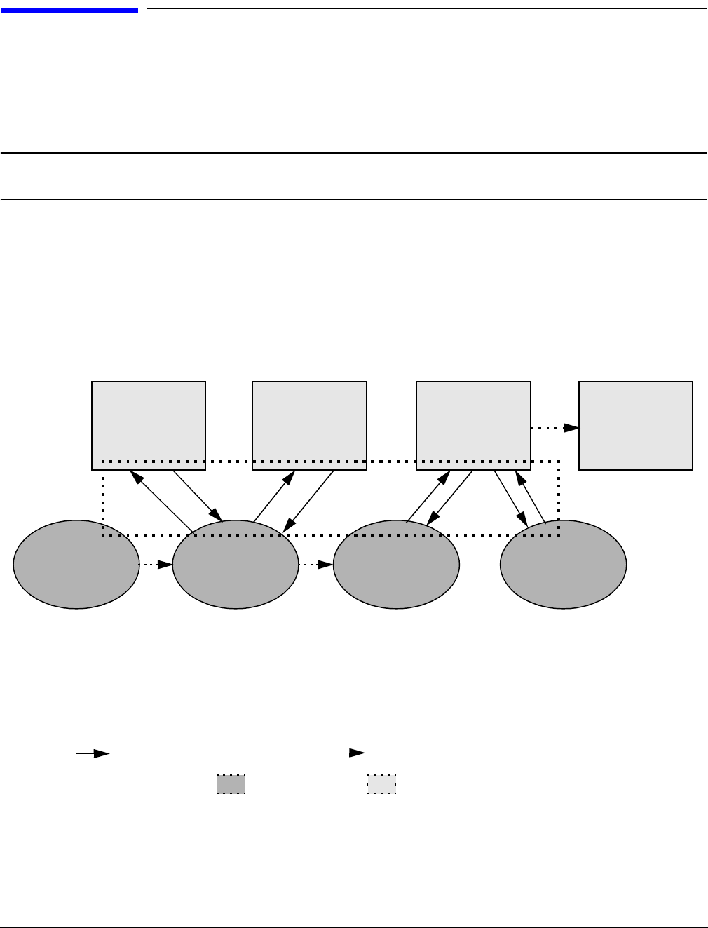
Appendix C
Utilities
Extensible Firmware Interface Boot Manager
162
Extensible Firmware Interface Boot Manager
Extensible Firmware Interface (EFI) is an OS and platform-independent boot and pre-boot interface. EFI
resides between the OS and platform firmware. This allows the OS to boot without having details about the
underlying hardware and firmware. EFI supports boot devices; uses a flat memory model; and hides platform
and firmware details from the OS.
NOTE EFI and Pre-OS System Environment (POSSE) are similar. EFI is an Intel specification,
whereas POSSE is the HP implementation that aids HP support.
EFI consolidates boot utilities similar to those found in PA-RISC based servers, such as the Boot Console
Handler (BCH), and platform firmware into a single platform firmware. EFI allows the selection of any EFI
OS loader from any boot medium that is supported by EFI boot services. An EFI OS loader supports multiple
options on the user interface.
EFI supports booting from media that contain an EFI OS loader or an EFI-defined server partition. An
EFI-defined server partition is required by EFI to boot from a block device.
Figure C-1 EFI Boot Sequence
EFI
Driver
EFI
Application
EFI
Bootcode
OS Loader
Retry Failure
EFI API
Platform
Init
EFI Image
Load
EFI
OS Loader
Load
Boot Services
Terminate
Standard
firmware
platform
initialization
Drivers and
application
loaded
iteratively
Boot from
ordered list
of EFI OS
loaders
Operation
handed off to
OS Loader
Application Program
Interface (API) specified Value add implementation
Boot manager EFI transfers

Appendix C
Utilities
Extensible Firmware Interface Boot Manager
163
The EFI boot manager loads EFI applications (including operating system [OS] first stage loader) and EFI
drivers from an EFI-defined file system or image loading service. Non-volatile RAM (NVRAM) variables point
to the file to be loaded. These variables contain application-specific data that is passed directly to the EFI
application. EFI variables provides system firmware a boot menu that points to all the operating systems,
even multiple versions of the same operating systems.
The EFI boot manager allows you to control the server’s booting environment. Depending on how you have
configured the boot options, after the server is powered up the boot manager presents you with different ways
to bring up the server. For example, you can boot to the EFI shell, to an operating system located on the
network or residing on media in the server, or the Boot Configuration menu, see “Using the Boot
Configuration Menu”.
•Boot From File—Allows the user to explore the EFI file system and to choose a file to boot. The selected
file will not be added to the boot option list.
•Add Boot Entry—Adds a boot option to the EFI boot manager. You select the boot option by exploring the
available file systems for the EFI file you wish to add. After selecting the file, you will be prompted for the
name of the boot option and for any optional ASCII or UNICODE arguments the file might use. After
saving the boot option you may boot it by selecting it from the list of available boot options in the boot
menu.
•Remove Boot Entry—Deletes a specific boot entry or all boot entries.
•Edit OS Boot Order—Controls the relative order in which the EFI boot manager attempts boot options.
For help on the control key sequences you need for this option, see the help menu.
•BootNext Configuration—Selects a boot option to use one time (the next boot operation).
•AutoBoot Configuration—Defines the value in seconds that pass before the server automatically boots
without user intervention. Setting this value to zero disables the timeout feature.

Appendix C
Utilities
Extensible Firmware Interface Boot Manager
164
EFI Commands
Table C-1 lists EFI commands for the HP Integrity rx4640 server. The equivalent BCH commands found in
PA-RISC based servers are also listed.
Table C-1 EFI Commands
EFI Shell
Command
BCH
Command
Equivalent
(PA-RISC)
BCH Command Parameters
(PA-RISC) Definition
These commands are found in all other menus
info boot Boot [PRI|HAA|ALT|<path>] Boot from specified path
help <command> HElp [<menu>|<command>] Display help for specified
command or menu
reset RESET Reset the server (to allow
reconfiguration of
complex
exit (at EFI shell) MAin Return to the main menu
MAin
EFI boot manager
“change boot
order”
PAth [PRI|HAA|ALT|CON|KEY|<path>] Display or modify a path
bcfg SEArch [ALL] Search for boot devices
bcfg SEArch [DIsplay|IPL] [<path>] Search for boot devices
many commands
offer a [-b]
parameter to cause
25 line breaks
ScRoll [ON|OFF] Display or change
scrolling capability
COnfiguration
autoboot AUto [BOot|SEarch|STart] [ON|OFF] Display or set the auto
start flag
info boot BootID [<processor #>[<bootid #>]] Display or set processor
boot identifier
EFI boot manager Boot info Display boot-related
information
autoboot BootTimer [0-200] Seconds allowed for boot
attempt
cpuconfig CPUconfig [<cpu>][ON|OFF]] Config/deconfig processor
boottest FastBoot [ON|OFF] or [test] [RUN|SKIP] Display or set boot tests
execution

Appendix C
Utilities
Extensible Firmware Interface Boot Manager
165
date Time [cn:yr:mo:dy:hr:mn[:ss]] Read or set the date
time Time [cn:yr:mo:dy:hr:mn[:ss]] Read or set the real time
clock
INformation
info all ALL Display all server
information
info boot BootINfo Display boot-releated
information
info cpu CAche Display cache
information
info chiprev ChipRevisions Display revision number
of major VLSI
MP command <df> FRU Display FRU information
info fw FwrVersion Display firmware version
for PDC, ICM, and
complex
info io IO Display firmware version
for PDC, ICM, and
complex
lanaddress LanAddress Display core LAN station
address
info mem Memory Display memory
information
info cpu PRocessor Display processor
information
SERvice
errdump clear CLEARPIM Clear (zero) the contents
of PIM
mm MemRead <addr> [<len>] [<type>] Read memory locations
scope of page
deallocation
pdt page
deallocation
table (pdt)
Display or clear the page
deallocation table
Table C-1 EFI Commands (Continued)
EFI Shell
Command
BCH
Command
Equivalent
(PA-RISC)
BCH Command Parameters
(PA-RISC) Definition

Appendix C
Utilities
EFI/POSSE Commands
166
EFI/POSSE Commands
This section describes the EFI/POSSE commands developed for the server.
NOTE EFI and Pre-OS System Environment (POSSE) are similar. EFI is an Intel specification,
whereas POSSE is the HP implementation that aids HP support.
help
Provides information on the EFI shell commands. It also has an additional feature to aid those familiar with
the BCH menus of PA-RISC servers to adjust to their equivalent functions in EFI.
Syntax
help [-b] <category>
help [-b] <cmd>
help [-b] bch <bchmenu> <bchcmd>
Parameters
-b Enable page breaking
category Category of commands to view help on commands
cmd Shell command name on which to provide verbose information
bch Display the list of BCH commands and their corresponding EFI
bchmenu BCH menu name taken from the top level of the BCH menu
bchcmd BCH command on which to display information
Operation
If help is initiated with no parameters, it displays a list of shell command categories. To list all of the
commands within a category, the user should enter help <category> (see examples). If initiated with the -b
switch, any output longer than one page pauses after each page is displayed. If a shell command name is used
as a parameter, verbose help is displayed for that command.
If help is initiated with the bch option, it displays a list of BCH commands and their corresponding
EFI/POSSE commands. It instructs the user to repeat the command line followed by a menu name for more
information on that menu. If help is initiated followed by bch and a menu name, it displays a list of
commands that appear under that BCH menu. The user may then initiate help followed by bch, the menu
name, and a BCH command name to display information on that command. This would point the user to the
errdump cmc
errdump init
processor
internal
memory (PIM)
[<proc>] [HPMC|LPMC|TOC|ASIC]] Display PIM information
Table C-1 EFI Commands (Continued)
EFI Shell
Command
BCH
Command
Equivalent
(PA-RISC)
BCH Command Parameters
(PA-RISC) Definition

Appendix C
Utilities
EFI/POSSE Commands
167
command that has taken the place of that BCH functionality, or will inform the user that the functionality no
longer exists. As a shortcut, the user may enter help followed by bch and a BCH command name to go straight
to that command.
Example C-1 help Command
Shell> help
List of classes of commands:
boot -- Booting options and disk-related commands
configuration -- Changing and retrieving system information
devices -- Getting device, driver and handle information
memory -- Memory related commands
shell -- Basic shell navigation and customization
scripts -- EFI shell-script commandsType "help" followed by a class name for a list of commands in
that class
Type "help" followed by command name for full documentation
Example C-2 help bch Command
COnfiguration help bch co
INformation help bch in
PAth help bch pa
ScRool help bch sr
SEArch help bch sea
SERvice help bch ser
BOot help bch bo
HElp help bch he
RESET help bch reset
MAin help bch ma
For more help on one of the commands above, at the prompt type:
help bch <bchcmd>
Example C-3 help configuration Command
Shell> help configuration
Configuration commands:
cpuconfig -- Deconfigure or reconfigure cpus
date -- Display or set date
err -- Display or set error level
esiproc -- Make an ESI call
errdump -- View/Clear logs
info -- Display hardware information
monarch -- View or set the monarch processor
palproc -- Make a PAL call
salproc -- Make a SAL call
time -- Display or set time
ver -- Displays version info
Type "help" followed by command name for full documentationon that command.
Type "help -a" to display a list of all commands.
Example C-4 help cpuconfig Command
Shell> help cpuconfig
Deconfigure or reconfigure cpus
CPUCONFIG [cpu] [on|off]
cpu Specifies which cpu to configure
on|off Specifies to configure or deconfigure a cpu
Notes:
1. Cpu status will not change until next boot

Appendix C
Utilities
EFI/POSSE Commands
168
2. Specifying a cpu number without a state will display
configuration status.
Examples:
* To deconfigure CPU 0
fs0:\> cpuconfig 0 off
CPU will be deconfigured on the next boot
* To display configuration status of cpus
fs0:\> cpuconfig
<CPU configuration data displayed>
baud
Sets the baud rate and communication settings for a UART.
Syntax
baud <index> <baudrate>
Parameters
<index> 0 through the total number of UARTS minus one
<baudrate> baud rate.
Operation
This command is used to change the speed for a UART in the server. This command works for all UARTs
visible to EFI/POSSE. If the UART is part of processor dependent hardware (PDH) space and is initialized by
the core firmware, this command communicates the settings to core firmware so the UART can be initialized
with the new settings on the next boot. Server default is 9600 baud.
Other Communication parameters are listed in Table C-2.
boottest
Interacts with the speedy boot variable allowing it to be set appropriately.
Syntax
boottest Displays status of all speedy boot bits
boottest on Run all tests (for a normal boot time)
boottest off Skip all tests (for a faster boot time)
boottest [test] Displays status of specific Speedy Boot bit
boottest [test] [on|off] Sets or clears a specific Speedy Boot bit
Table C-2 Communications Parameters
Parameter Value
RECEIVE_FIFO_DEPTH 1
TIMEOUT 1000000
PARITY No parity
DATA_BITS 8
STOP_BITS 1
CONTROL_MASK 0

Appendix C
Utilities
EFI/POSSE Commands
169
Parameters
[test] Each test can be set or cleared:
booting_valid Enable/disable system firmware response to BOOTING
bit. If OS Speedy Boot aware set to on.
early_cpu Enable/disable early CPU selftests.
late_cpu Enable/disable late CPU selftests.
platform Enable/disable system board hardware tests.
chipset Enable/disable CEC tests.
io_hw Enable/disable EFI driver Core I/O tests.
mem_init Enable/disable memory initialization.
mem_test Enable/disable full destructive memory tests.
Example C-5 boottest Command
Shell> boottest
BOOTTEST Settings Default Variable
Selftest Setting
------------- -------------------------
booting_valid On (OS speedy boot aware)
early_cpu Run this test
late_cpu Run this test
platform Run this test
chipset Run this test
io_hw Run this test
mem_init Run this test
mem_test Run this test
Example C-6 boottest early_cpu off Command
Shell> boottest early_cpu off
BOOTTEST Settings Default Variable
Selftest Setting
------------- -------------------------
booting_valid On (OS speedy boot aware)
early_cpu Skip this test
late_cpu Run this test
platform Run this test
chipset Run this test
io_hw Run this test
mem_init Run this test
mem_test Run this test
cpuconfig
Displays the config/deconfig state of processors in the server and allows the user to configure or reconfigure
processors.
Syntax
cpuconfig <cpu> <on|off>
Parameters
<cpu> specify a processor
<on|off> state to set the processor to

Appendix C
Utilities
EFI/POSSE Commands
170
Operation
Issuing cpuconfig with no parameters displays the config/deconfig status of all processors. A user can
reconfigure CPUs by specifying a CPU number and a state (on or off). If a valid state is entered and is
different from the current state of a CPU, its status changes on the next boot. The last remaining configured
CPU in a server cannot be deconfigured.
Example C-7 cpuconfig Command
Shell> cpuconfig
PROCESSOR INFORMATION
Proc Arch Processor
CPU Speed Rev Model Family Rev State
--- ------- --------- ------- ----- ------ -----
0 560Mhz B1 0 31 0 Sched Deconf
1 560Mhz B1 0 31 0 Active
ioconfig
Use this command to deconfigure or reconfigure I/O components or settings.
Syntax
ioconfig <fast_init | wol> <on|off>
Parameters
<fast_init> specify device connection policy setting
<wol> specify system wake-on-lan setting
<on|off> specify to configure or deconfigure a feature or component
Operation
The ioconfig file is used to retain information on the server I/O configuration across reboots. The ioconfig
file is created by insf at install time; and is modified by insf, rmsf, and ioscan when devices are added or
removed. The only purpose of the ioconfig file to maintain configuration information when the system is
not running.
Example C-8 ioconfig Command
Shell> ioconfig
Deconfigure or reconfigure IO components or settings
IOCONFIG [fast_init|wol [on|off]]
fast_init Specifies device connection policy setting
wol Specifies System Wake-On-LAN setting
on|off Specifies to configure or deconfigure a feature or component
Note:
1. If fast_init is enabled, firmware will connect only the minimum set of
devices during boot. This feature might cause boot failure; disable this
feature if failure occurs.
2. Any pending Wake-On-LAN request will not be cleared until reboot if
the setting is changed to disabled.
System will clear pending Wake-On-LAN requests each time the system
reboots if the setting is disabled.

Appendix C
Utilities
EFI/POSSE Commands
171
Examples:
* To display the current settings
fs0:\> ioconfig
Fast initialization: Enabled
System Wake-On-LAN: Disabled
* To display the current device connection policy setting
fs0:\> ioconfig fast_init
Fast initialization: Enabled
* To disable fast initialization
fs0:\> ioconfig fast_init off
Fast initialization: Disabled
* To enable the System Wake-On-LAN setting
fs0:\> ioconfig wol on
System Wake-On-LAN: Enabled
default
Allows the user to restore non-volatile memory (NVM) to default values and clear NVM storage values.
Syntax
default [efi|sal]
default clear [bmc|efi|sal]
Parameters
clear clears NVM storage values
Operation
Default sets NVM and stable store values to predefined default values. To the normal user only a subset of
values are available for default. Executing “default clear” resets the server.
errdump
Displays the contents of processor internal memory logged for all processors present in the server.
Syntax
errdump [cpe | cmc | init | la | clear]
Parameters
cpe dumps the Corrected Platform Error log
cmc dumps the Corrected Machine Check log
init dumps the Initialization log
la dumps the Logic Analyzer log
clear erases all of the logs (cpe, cmc, init, la)

Appendix C
Utilities
EFI/POSSE Commands
172
Operation
If a user enters no parameters, the usage is displayed. Otherwise, the specified error log is displayed. Adding
-n to the clear parameter disables the confirmation prompt. (The errdump command can also be accessed
through the server Configuration menu.)
info
Allows the user to display most server information.
Syntax
info [ -b] [target]
Parameters
target: valid targets are:
all display everything
cpu display information on cpus
cache display information on cache
mem display information on memory
io display information on io
boot display boot-related information
chiprev display information on chip revisions
fw display firmware version information
sys display system information
warning display warning and stop boot information
Example C-9 info all Command
Shell> info all
SYSTEM INFORMATION
Date/Time: Sep 24, 2004 17:27:17 (20:04:09:24:17:27:17)
Manufacturer: hp
Product Name: server rx4640
Product Number: AB333A
Serial Number: USR0418201
UUID: 336B81EE-A9AF-11D8-9653-3F6E1533CC31
System Bus Frequency: 200 MHz
PROCESSOR MODULE INFORMATION
# of L3 L4 Family/
CPU Logical Cache Cache Model Processor
Module CPUs Speed Size Size (hex.) Rev State
------ ------- -------- ------ ------ ------- --- ------------
0 1 1.3 GHz 3 MB None 1F/01 B1 Active
MEMORY INFORMATION
---- DIMM A ----- ---- DIMM B -----
DIMM Current DIMM Current
--- ------ ---------- ------ ----------
0 256MB Active 256MB Active
1 256MB Active 256MB Active
2 ---- ----
3 ---- ----
4 ---- ----
5 ---- ----
Active Memory : 1024 MB
Installed Memory : 1024 MB
I/O INFORMATION

Appendix C
Utilities
EFI/POSSE Commands
173
BOOTABLE DEVICES
Order Media Type Path
----- ---------- ---------------------------------------
1 CDROM Acpi(HWP0002,0)/Pci(2|0)/Ata(Primary,Master)/CDROM(Entry0)
Seg Bus Dev Fnc Vendor Device Slot
# # # # ID ID # Path
--- --- --- --- ------ ------ --- -----------
00 00 01 00 0x1033 0x0035 XX Acpi(HWP0002,0)/Pci(1|0)
00 00 01 01 0x1033 0x0035 XX Acpi(HWP0002,0)/Pci(1|1)
00 00 01 02 0x1033 0x00E0 XX Acpi(HWP0002,0)/Pci(1|2)
00 00 02 00 0x1095 0x0649 XX Acpi(HWP0002,0)/Pci(2|0)
00 20 01 00 0x1000 0x0030 XX Acpi(HWP0002,100)/Pci(1|0)
00 20 01 01 0x1000 0x0030 XX Acpi(HWP0002,100)/Pci(1|1)
00 20 02 00 0x8086 0x1079 XX Acpi(HWP0002,100)/Pci(2|0)
00 20 02 01 0x8086 0x1079 XX Acpi(HWP0002,100)/Pci(2|1)
00 40 01 00 0x1000 0x0021 03 Acpi(HWP0002,200)/Pci(1|0)
00 60 01 00 0x1077 0x2312 02 Acpi(HWP0002,300)/Pci(1|0)
00 60 01 01 0x1077 0x2312 02 Acpi(HWP0002,300)/Pci(1|1)
00 80 01 00 0x1000 0x000F 01 Acpi(HWP0002,400)/Pci(1|0)
00 80 01 01 0x1000 0x000F 01 Acpi(HWP0002,400)/Pci(1|1)
00 C0 01 00 0x1000 0x0021 04 Acpi(HWP0002,600)/Pci(1|0)
00 E0 01 00 0x103C 0x1290 XX Acpi(HWP0002,700)/Pci(1|0)
00 E0 01 01 0x103C 0x1048 XX Acpi(HWP0002,700)/Pci(1|1)
00 E0 02 00 0x1002 0x5159 XX Acpi(HWP0002,700)/Pci(2|0)
System Wake-On-LAN: Enabled
BOOT INFORMATION
Monarch CPU:
Current Preferred
Monarch Monarch
CPU CPU
Module/ Module/
Logical Logical Warnings
------- --------- --------
0/0 0/0
AutoBoot: ON - Timeout is : 10 sec
Boottest:
BOOTTEST Settings Default Variable
OS is not speedy boot aware.
Selftest Setting
--------- --------------
early_cpu Run this test
late_cpu Run this test
platform Run this test
chipset Run this test
io_hw Run this test
mem_init Run this test
mem_test Run this test
LAN Address Information:

Appendix C
Utilities
EFI/POSSE Commands
174
LAN Address Path
----------------- ----------------------------------------
*Mac(000E7F7E07FA) Acpi(HWP0002,100)/Pci(2|0)/Mac(000E7F7E07FA))
Mac(000E7F7E07FB) Acpi(HWP0002,100)/Pci(2|1)/Mac(000E7F7E07FB))
FIRMWARE INFORMATION
Firmware Revision: 86.10 [4432]
PAL_A: 7.31/5.37
PAL_B: 5.69
EFI Spec: 1.10
EFI Intel Drop: 14.62
EFI Build: 86.10
SAL Spec: 3.01
SAL_A: 2.00
SAL_B: 86.10
POSSE: 0.10
ACPI: 7.00
SMBIOS: 2.3.2a:
BMC Revision: 3.42
IPMI: 1.00
Management Processor Revision: E.03.02
Updatable EFI Drivers:
************ 2nd part **********************
Seg Bus Dev Fnc Vendor Device Slot
# # # # ID ID # Path
--- --- --- --- ------ ------ --- -----------
00 00 01 00 0x1033 0x0035 XX Acpi(HWP0002,0)/Pci(1|0)
00 00 01 01 0x1033 0x0035 XX Acpi(HWP0002,0)/Pci(1|1)
00 00 01 02 0x1033 0x00E0 XX Acpi(HWP0002,0)/Pci(1|2)
00 00 02 00 0x1095 0x0649 XX Acpi(HWP0002,0)/Pci(2|0)
00 20 01 00 0x1000 0x0030 XX Acpi(HWP0002,100)/Pci(1|0)
00 20 01 01 0x1000 0x0030 XX Acpi(HWP0002,100)/Pci(1|1)
00 20 02 00 0x8086 0x1079 XX Acpi(HWP0002,100)/Pci(2|0)
00 20 02 01 0x8086 0x1079 XX Acpi(HWP0002,100)/Pci(2|1)
00 40 01 00 0x1000 0x0021 03 Acpi(HWP0002,200)/Pci(1|0)
00 60 01 00 0x1077 0x2312 02 Acpi(HWP0002,300)/Pci(1|0)
00 60 01 01 0x1077 0x2312 02 Acpi(HWP0002,300)/Pci(1|1)
00 80 01 00 0x1000 0x000F 01 Acpi(HWP0002,400)/Pci(1|0)
00 80 01 01 0x1000 0x000F 01 Acpi(HWP0002,400)/Pci(1|1)
00 C0 01 00 0x1000 0x0021 04 Acpi(HWP0002,600)/Pci(1|0)
00 E0 01 00 0x103C 0x1290 XX Acpi(HWP0002,700)/Pci(1|0)
00 E0 01 01 0x103C 0x1048 XX Acpi(HWP0002,700)/Pci(1|1)
00 E0 02 00 0x1002 0x5159 XX Acpi(HWP0002,700)/Pci(2|0)
System Wake-On-LAN: Enabled
BOOT INFORMATION
Monarch CPU:
Current Preferred
Monarch Monarch
CPU CPU
Module/ Module/
Logical Logical Warnings
------- --------- --------
0/0 0/0
AutoBoot: ON - Timeout is : 10 sec

Appendix C
Utilities
EFI/POSSE Commands
175
Boottest:
BOOTTEST Settings Default Variable
OS is not speedy boot aware.
Selftest Setting
--------- --------------
early_cpu Run this test
late_cpu Run this test
platform Run this test
chipset Run this test
io_hw Run this test
mem_init Run this test
mem_test Run this test
LAN Address Information:
LAN Address Path
----------------- ----------------------------------------
*Mac(000E7F7E07FA) Acpi(HWP0002,100)/Pci(2|0)/Mac(000E7F7E07FA))
Mac(000E7F7E07FB) Acpi(HWP0002,100)/Pci(2|1)/Mac(000E7F7E07FB))
FIRMWARE INFORMATION
Firmware Revision: 86.10 [4432]
PAL_A: 7.31/5.37
PAL_B: 5.69
EFI Spec: 1.10
EFI Intel Drop: 14.62
EFI Build: 86.10
SAL Spec: 3.01
SAL_A: 2.00
SAL_B: 86.10
POSSE: 0.10
ACPI: 7.00
SMBIOS: 2.3.2a:
BMC Revision: 3.42
IPMI: 1.00
Management Processor Revision: E.03.02
Updatable EFI Drivers:
Floating-Point Software Assistance Handler: 00000118
LSI Logic Ultra320 SCSI Driver: 01030000
Broadcom Gigabit Ethernet Driver: 00070003
Intel(R) PRO/1000 Ethernet Driver: 00002160
WARNING AND STOP BOOT INFORMATION
Error[55] : Invalid or inaccessible system ID(s)
CHIP REVISION INFORMATION
Chip Logical Device Chip
Type ID ID Revision
------------------- ------- ------ --------
Memory Controller 0 122b 0023
Root Bridge 0 1229 0023
Host Bridge 0000 122e 0032
Host Bridge 0001 122e 0032
Host Bridge 0002 122e 0032
Host Bridge 0003 122e 0032
Host Bridge 0004 122e 0032
Host Bridge 0006 122e 0032
Host Bridge 0007 122e 0032

Appendix C
Utilities
EFI/POSSE Commands
176
Other Bridge 0 0 0002
Other Bridge 0 0 0009
Baseboard MC 0 0 0342
Example C-10 info cpu Command
Shell> info cpu
PROCESSOR MODULE INFORMATION
# of L3 L4 Family/
CPU Logical Cache Cache Model Processor
Module CPUs Speed Size Size (hex.) Rev State
------ ------- -------- ------ ------ ------- --- ------------
0 4 1.4 GHz 6 MB None 20/00 B0 Active
1 4 1.4 GHz 6 MB None 20/00 B0 Active
CPU threads are turned on.
Example C-11 info mem Command
Shell> info mem
MEMORY INFORMATION
---- DIMM A ----- ---- DIMM B -----
DIMM Current DIMM Current
--- ------ ---------- ------ ----------
0 256MB Active 256MB Active
1 256MB Active 256MB Active
2 ---- ----
3 ---- ----
4 ---- ----
5 ---- ----
Active Memory : 1024 MB
Installed Memory : 1024 MB
Example C-12 info io Command
Shell> info io
I/O INFORMATION
BOOTABLE DEVICES
Order Media Type Path
----- ---------- ---------------------------------------
1 CDROM Acpi(HWP0002,0)/Pci(2|0)/Ata(Primary,Master)/CDROM(Entry0)
Seg Bus Dev Fnc Vendor Device Slot
# # # # ID ID # Path
--- --- --- --- ------ ------ --- -----------
00 00 01 00 0x1033 0x0035 XX Acpi(HWP0002,0)/Pci(1|0)
00 00 01 01 0x1033 0x0035 XX Acpi(HWP0002,0)/Pci(1|1)
00 00 01 02 0x1033 0x00E0 XX Acpi(HWP0002,0)/Pci(1|2)
00 00 02 00 0x1095 0x0649 XX Acpi(HWP0002,0)/Pci(2|0)
00 20 01 00 0x1000 0x0030 XX Acpi(HWP0002,100)/Pci(1|0)
00 20 01 01 0x1000 0x0030 XX Acpi(HWP0002,100)/Pci(1|1)
00 20 02 00 0x8086 0x1079 XX Acpi(HWP0002,100)/Pci(2|0)

Appendix C
Utilities
EFI/POSSE Commands
177
00 20 02 01 0x8086 0x1079 XX Acpi(HWP0002,100)/Pci(2|1)
00 40 01 00 0x1000 0x0021 03 Acpi(HWP0002,200)/Pci(1|0)
00 60 01 00 0x1077 0x2312 02 Acpi(HWP0002,300)/Pci(1|0)
00 60 01 01 0x1077 0x2312 02 Acpi(HWP0002,300)/Pci(1|1)
00 80 01 00 0x1000 0x000F 01 Acpi(HWP0002,400)/Pci(1|0)
00 80 01 01 0x1000 0x000F 01 Acpi(HWP0002,400)/Pci(1|1)
00 C0 01 00 0x1000 0x0021 04 Acpi(HWP0002,600)/Pci(1|0)
00 E0 01 00 0x103C 0x1290 XX Acpi(HWP0002,700)/Pci(1|0)
00 E0 01 01 0x103C 0x1048 XX Acpi(HWP0002,700)/Pci(1|1)
00 E0 02 00 0x1002 0x5159 XX Acpi(HWP0002,700)/Pci(2|0)
System Wake-On-LAN: Enabled
Example C-13 info boot Command
Shell> info boot
BOOT INFORMATION
Monarch CPU:
Current Preferred
Monarch Monarch
CPU CPU
Module/ Module/
Logical Logical Warnings
------- --------- --------
0/0 0/0
AutoBoot: ON - Timeout is : 10 sec
Boottest:
BOOTTEST Settings Default Variable
OS is not speedy boot aware.
Selftest Setting
--------- --------------
early_cpu Run this test
late_cpu Run this test
platform Run this test
chipset Run this test
io_hw Run this test
mem_init Run this test
mem_test Run this test
LAN Address Information:
LAN Address Path
----------------- ----------------------------------------
*Mac(000E7F7E07FA) Acpi(HWP0002,100)/Pci(2|0)/Mac(000E7F7E07FA))
Mac(000E7F7E07FB) Acpi(HWP0002,100)/Pci(2|1)/Mac(000E7F7E07FB))
lanaddress
Allows the user to display the core I/O MAC address.
Syntax:
lanaddress

Appendix C
Utilities
EFI/POSSE Commands
178
Parameters
none
Example C-14 lanaddress Command
LAN Address Information:
LAN Address Path
----------------- ----------------------------------------
Mac(00306E4C4F1A) Acpi(HWP0002,0)/Pci(3|0)/Mac(00306E4C4F1A))
*Mac(00306E4C0FF2) Acpi(HWP0002,100)/Pci(2|0)/Mac(00306E4C0FF2))
monarch
Displays or modifies the ID of the bootstrap processor. The preferred monarch number is stored in NVM.
Syntax
monarch <cpu>
Parameters
<cpu> specifies a cpu
Operation
If specified with no parameters, monarch displays the Monarch processor for the server. Specifying a
processor number alters the preferred Monarch processor. None of these changes takes affect until after a
reboot.
Example C-15 monarch Command
Shell> monarch
Current Preferred
Monarch Monarch Possible Warnings
------- --------- -----------------
00
00
To view monarch: fs0 :\ monarch
| Processor
-----------------+-----------
current status | 0
next boot status | 0
To set the monarch processor to 1: fs0 :\ monarch 1
| Processor
-----------------+-----------
current status | 0
next boot status | 1
pdt
Displays or clears the contents of the Page Deallocation Table.

Appendix C
Utilities
EFI/POSSE Commands
179
Syntax
pdt (clear)
Parameters
<clear> clears the pdt
Operation
With no options specified, the command displays the PDT information for the server. The PDT is cleared and
a reboot is required for memory reallocation and safe booting.
Example C-16 pdt Command
Shell> pdt
PDT Information for PD
Last Clear time for PD: PDT has not been cleared
Number of total entries in PD PDT: 100
Number of used entries in PD PDT: 0
Number of free entries in PD PDT: 50
Number of permanent correctable (SBE) entries in PD PDT: 0
Number of permanent uncorrectable (MBE) entries in PD PDT: 0
Address of first uncorrectable error in PD: 0x0000000000000000
Example C-17 pdt clear Command
Shell> pdt clear
Are you sure you want to clear the PDT? [y/N] y
Shell>
Shell> pdt
PDT Information
Last Clear time: 10/21/01 5:00p
Number of total entries in PDT: 50
Number of used entries in PDT: 0
Number of free entries in PDT: 50
Number of single-bit entries in PDT: 0
Number of multi-bit entries in PDT: 0
Address of first multi-bit error: 0x0000000000000000
sysmode
Display or modify the system mode.
Syntax
sysmode <normal | admin| service>
Parameters
<normal> sets system mode to normal
<admin> sets system mode to admin
<service> sets system mode to service

Appendix C
Utilities
Specifying SCSI Parameters
180
Operation
If specified alone, sysmode displays the system mode. If a mode is specified as a parameter, then the system
mode is changed. This new mode takes effect immediately. The system mode is retained on successive boots.
Interaction with sysmode in a variety of scenarios is outlined below.
Example C-18 sysmode Command
Shell> sysmode
System Mode: NORMAL
Shell> sysmode admin
You are now in admin mode.
Shell> sysmode service
You are now in service mode.
Shell> sysmode normal
You are now in normal mode
Specifying SCSI Parameters
The following SCSI parameters may be configured for the SCSI board:
• SCSI ID (SCSI initiator ID)
• Maximum data transfer rate (SCSI rate)
•Bus width
• Whether the HBA is bootable (driver support)
• Avoid bus resets (secondary cluster server)
Using the SCSI Setup Utility
Step 1. At the EFI shell prompt, enter the following command to map the parameters for all PCI cards
installed in the server:
info io
A list of all the devices that are installed in the HP Integrity rx4640 server and managed by EFI
drivers is displayed. The output may look like this:

Appendix C
Utilities
Specifying SCSI Parameters
181
I/O INFORMATION
BOOTABLE DEVICES
Order Media Type Path
----- ---------- ---------------------------------------
1 CDROM Acpi(HWP0002,0)/Pci(2|0)/Ata(Primary,Master)/CDROM(Entry0)
Seg Bus Dev Fnc Vendor Device Slot
# # # # ID ID # Path
--- --- --- --- ------ ------ --- -----------
00 00 01 00 0x1033 0x0035 XX Acpi(HWP0002,0)/Pci(1|0)
00 00 01 01 0x1033 0x0035 XX Acpi(HWP0002,0)/Pci(1|1)
00 00 01 02 0x1033 0x00E0 XX Acpi(HWP0002,0)/Pci(1|2)
00 00 02 00 0x1095 0x0649 XX Acpi(HWP0002,0)/Pci(2|0)
00 20 01 00 0x1000 0x0030 XX Acpi(HWP0002,100)/Pci(1|0)
00 20 01 01 0x1000 0x0030 XX Acpi(HWP0002,100)/Pci(1|1)
00 20 02 00 0x8086 0x1079 XX Acpi(HWP0002,100)/Pci(2|0)
00 20 02 01 0x8086 0x1079 XX Acpi(HWP0002,100)/Pci(2|1)
00 40 01 00 0x1000 0x0021 03 Acpi(HWP0002,200)/Pci(1|0)
00 60 01 00 0x1077 0x2312 02 Acpi(HWP0002,300)/Pci(1|0)
00 60 01 01 0x1077 0x2312 02 Acpi(HWP0002,300)/Pci(1|1)
00 80 01 00 0x1000 0x000F 01 Acpi(HWP0002,400)/Pci(1|0)
00 80 01 01 0x1000 0x000F 01 Acpi(HWP0002,400)/Pci(1|1)
00 C0 01 00 0x1000 0x0021 04 Acpi(HWP0002,600)/Pci(1|0)
00 E0 01 00 0x103C 0x1290 XX Acpi(HWP0002,700)/Pci(1|0)
00 E0 01 01 0x103C 0x1048 XX Acpi(HWP0002,700)/Pci(1|1)
00 E0 02 00 0x1002 0x5159 XX Acpi(HWP0002,700)/Pci(2|0)
System Wake-On-LAN: Enabled
In the preceding example, a single SCSI interface is shown in the listing. The information for both
channels of the SCSI interface is shown in bold, for highlighting purposes.
For each channel of the SCSI board, you need to note certain information. As an example, look at
the information for the SCSI interface (the first two bold lines). For each channel of this SCSI
interface, note the following information:
•Bus #—identifies the bus the device is on; for the SCSI interface, this is the same for both
channels. In this example, the bus number is 20.
•Dev #—the ID the device is assigned on the bus; for the SCSI interface, this is the same for
both channels. In this example, the SCSI interface is device 01.
•Fnc #—identifies the channel of the device (00 for channel A, 01 for channel B, and so on). In
this example, because the SCSI interface has two channels, one channel is 00 and the other is
01.
•Vendor ID—shows the device’s vendor ID; for the SCSI interface, this is the same for both
channels. For all the SCSI interface the ID is 0x1000.
•Device ID—shows the device ID; for the SCSI interface, this is the same for both channels. For
the SCSI interface the ID is 0x0030.
•Slot #—identifies the physical card slot in the server where the SCSI interface is installed; for
the SCSI interface, this is the same for both channels. In this example, the SCSI interface is on
the I/O baseboard therefore the in slot number is xx.
•Path—identifies the device’s path; for the SCSI interface, this is the same for both channels. In
this example, the SCSI interface path is Acpi(HWP0002,200)/Pci(1|0) for channel A and
Acpi(HWP0002,200)/Pci(1|1) for channel B.

Appendix C
Utilities
Specifying SCSI Parameters
182
Using the SCSI interface information from the example above, the pieces of information that,
combined, tell you this is a SCSI interface are the following (shown in bold, for highlighting
purposes):
00 20 01 00 0x1000 0x0030 xx Acpi(HWP0002,200)/Pci(1|0)
00 20 01 01 0x1000 0x0030 xx Acpi(HWP0002,200)/Pci(1|1)
Looking at all of the above information together, the vendor (0x1000) and device (0x0030) are the
IDs for a SCSI interface. Of the devices with those IDs, this device has two channels (Fnc # of 00
immediately followed by Fnc # of 01). Also, this SCSI interface has a non-numeric (XX) slot #
indicating that it is on the I/O baseboard.
Step 2. Still at the EFI shell prompt, enter the following command to obtain the controller’s handle for the
SCSI interface:
devtree
A tree of all EFI-capable devices installed in the server is displayed. The output could look like this:
Shell> devtree
Device Tree
Ctrl[04]
Ctrl[06] VenHw(SysROM)
Ctrl[0B] Acpi(HWP0002,0)
Ctrl[15] Usb Open Host Controller
Ctrl[16] Usb Open Host Controller
Ctrl[17] Acpi(HWP0002,0)/Pci(1|2)
Ctrl[18] PCI IDE/ATAPI Controller
Ctrl[56] DV-28E-C
Ctrl[91] FAT File System [FAT32] 118 MB
Ctrl[0C] Acpi(HWP0002,100)
Ctrl[1C] LSI Logic Ultra320 SCSI Controller
Ctrl[1D] LSI Logic Ultra320 SCSI Controller
Ctrl[1E] Acpi(HWP0002,100)/Pci(2|0)
Ctrl[57] Acpi(HWP0002,100)/Pci(2|0)/Mac(000E7F7E07FA)
Ctrl[1F] Acpi(HWP0002,100)/Pci(2|1)
Ctrl[58] Acpi(HWP0002,100)/Pci(2|1)/Mac(000E7F7E07FB)
Ctrl[0D] Acpi(HWP0002,200)
Ctrl[20] Acpi(HWP0002,200)/Pci(1|0)
Ctrl[0E] Acpi(HWP0002,300)
Ctrl[22] HP 2 Gb Dual Port PCI/PCI-X Fibre Channel Adapter ( Port 1)
Ctrl[23] HP 2 Gb Dual Port PCI/PCI-X Fibre Channel Adapter ( Port 2)
Ctrl[0F] Acpi(HWP0002,400)
Ctrl[24] Acpi(HWP0002,400)/Pci(1|0)
Ctrl[25] Acpi(HWP0002,400)/Pci(1|1)
Ctrl[10] Acpi(HWP0002,600)
Ctrl[26] Acpi(HWP0002,600)/Pci(1|0)
Ctrl[11] Acpi(HWP0002,700)
Ctrl[27] Acpi(HWP0002,700)/Pci(1|0)
Ctrl[28] Acpi(HWP0002,700)/Pci(1|1)
Ctrl[43] 16550 Serial UART Driver
Ctrl[44] VT-100+ Serial Console
Ctrl[3E] Primary Console Input Device
Ctrl[3F] Primary Console Output Device
Ctrl[3D] Primary Standard Error Device
Ctrl[29] Acpi(HWP0002,700)/Pci(2|0)
Ctrl[40] Acpi(PNP0501,0)
Ctrl[41] 16550 Serial UART Driver
Ctrl[42] VT-100+ Serial Console
Ctrl[54] VenHw(D65A6B8C-71E5-4DF0-A909-F0D2992B5AA9)

Appendix C
Utilities
Specifying SCSI Parameters
183
In the preceding example, the SCSI interface information is shown highlighted bold. You can tell
the information is for the SCSI interface because the path on the first line—Acpi(HWP0002,100)—
is the path from the information displayed by the info io command. The next two lines are for the
SCSI interface two channels, one line for each channel (they contain the SCSI interface description
[LSI Logic Ultra320 SCSI Controller]). Note the value shown for Ctrl—17 and 18—at the
beginning of each of those lines; this is the controller’s handle for each channel. You need to
know it for the next step.
NOTE The controller’s handle values change on every boot.
Step 3. Still at the EFI shell prompt, enter the following command to obtain the EFI driver’s handle for the
SCSI interface:
drvcfg
A list of all EFI-capable configurable components in the server displays. The output may look like
this:
Shell> drvcfg
Configurable Components
Drv[3D] Ctrl[15] Lang[eng]
Drv[3F] Ctrl[19] Lang[eng]
Drv[45] Ctrl[17] Lang[eng]
Drv[45] Ctrl[18] Lang[eng]
This listing shows which driver controls which device (controller). In the above example, the SCSI
interface information is shown highlighted bold. You can tell the information is for this SCSI
interface because the values shown for Ctrl—17 and 18—are the controller’s handles for the SCSI
interface two channels (from the information displayed by the devtree command).
NOTE The EFI driver’s handle values change on every boot.
TIP From this command (drvcfg), we recommend you record these two pieces of
information for each channel of each SCSI interface for parameters to be changed:
•Drv (the EFI driver’s handle)
•Ctrl (the controller’s handle)
Step 4. Using the information (the driver’s handle [Drv] and the controller’s handle [Ctrl]) from the
drvcfg command, start the EFI SCSI Setup Utility for one channel of this SCSI interface. Still at
the EFI shell prompt, enter the following command:
drvcfg -s
drvr_handle cntrl_handle
where:
•
drvr_handle
is the handle of the driver that controls the channel whose SCSI ID you want to
display or change
•
cntrl_handle
is the handle of the controller for the channel whose SCSI ID you want to
display or change

Appendix C
Utilities
Specifying SCSI Parameters
184
Continuing the example for Channel A of this SCSI interface, you would enter:
drvcfg -s 45 18
Step 5. The EFI SCSI Setup Utility starts and its main menu displays, showing a list of all the EFI capable
SCSI interfaces in the server.
Move the cursor to highlight the channel of the SCSI interface; press Enter. (To determine which
channel of the interface to highlight, match the PCI Bus, PCI Dev, and PCI Func values on this
screen to the Bus #, Dev #, and Fnc # values from the info io command.)
CAUTION Do not select the <Global Properties> option on the main menu.
TIP To move the cursor in the EFI SCSI Setup Utility, you can use these keys:
• Arrow keys: ↑ ↓ ← →
•Alternate keys:
H = left
J = down
K = up
L = right
I = home
O = end
Step 6. The “Adapter Properties” screen for this channel of the SCSI interface is displayed. If you like, you
can make sure the utility is running for the channel of the SCSI interface by comparing the values
shown for PCI Bus, PCI Device, and PCI Function to the Bus #, Dev #, and Fnc # values from
the info io command.
CAUTION Do not change the value for any of these fields on the “Adapter Properties” screen:
•Auto Termination
•SCSI Parity
•SCSI Bus Scan Order
•Spinup Delay (Secs)
Changing any of these fields can cause unpredictable results.
CAUTION Do not change the value for any of these fields on the “Device Properties” screen:
•Scan Id
•Scan LUNs > 0

Appendix C
Utilities
Specifying SCSI Parameters
185
•Disconnect
•SCSI Timeout
•Queue Tags
•Format
•Verify
Changing any of these fields can cause unpredictable results.
Step 7. You may display (and optionally change) any SCSI parameters listed below for the channel of the
SCSI interface, or restore its SCSI parameters to their default values.
• SCSI ID
• Maximum data transfer rate
•Bus width
• Whether the SCSI interface is bootable (driver support)
• Avoid bus resets (secondary cluster server)
•Restore Defaults
Step 8. Use the arrow keys to navigate to the appropriate SCSI parameter.
Step 9. Use the plus (+) and minus (-) keys to scroll through the values.
Step 10. Press Esc to exit the Adapter Properties screen. You are given these choices:
• Cancel the exit from the screen (to stay in the Adapter Properties screen for the channel of the
SCSI interface)
• Save the changes you made and then exit the screen
• Discard the changes you made and then exit the screen
Step 11. Move the cursor to the action (cancel, save, or discard) you want to take; press Enter.
If you selected cancel, you remain in the Adapter Properties screen for the channel of the SCSI
interface. You can still change the channel’s parameters listed above.
If you selected save or discard, you are placed in the EFI SCSI Setup Utility’s main menu.
CAUTION Do not select the <Global Properties> option on the main menu.
Step 12. Press Esc to exit the main menu and the EFI SCSI Setup Utility.
Step 13. Select the option for exiting the utility.
Step 14. When you are prompted to, press Enter to stop the SCSI interface; you are now back at the EFI shell
prompt.
Step 15. At the EFI shell prompt, enter the reset command:
The server starts to reboot. This is required to cause the new SCSI setting.

Appendix C
Utilities
Using the Boot Configuration Menu
186
Using the Boot Configuration Menu
The Boot Configuration Menu menu allows you to select console output and input devices as well as various
boot options. It contains the following items:
• Boot From File
• Add Boot Entry
• Edit Boot Entry
• Remove Boot Entry
• Edit OS Boot Order
• AutoBoot Configuration
• BootNext Configuration
• Driver Configuration
• Console Configuration
•System Reset
These items are described in the following sections.
In all menus, select:
• For help on menus and navigation, see the status bar on the bottom of the screen
• Enter to select an item after using the arrow keys to highlight the item
• Save Settings to NVRAM to save your changes
NOTE The options shown here are examples. Your server may have different options available based
on the server configuration and installed hardware components.
Boot From File
Use this option to manually run a specific application or driver.
NOTE This option boots the selected application or driver one time only. When you exit the
application, you return to this menu.
This option displays the file systems that are on your server or workstation and lets you browse these file
systems for applications or drivers that are executable. Executable files end with the .efi extension. You can
also select remote boot (LAN) options that have been configured on your network.
For example:
Boot From a File. Select a Volume
NO VOLUME LABEL [Acpi(HWP0002,0)/Pci(2|0)/Ata(Primary,Master)/CDROM
CD_FORMAT [Acpi(HWP0002,0)/Pci(2|0)/Ata(Secondary,Master)/CDROM
Removable Media Boot [Acpi(HWP0002,500)/Pci(2|0)/Ata(Secondary,Master)
Load File [EFI Shell [Built-in]]

Appendix C
Utilities
Using the Boot Configuration Menu
187
Load File [Acpi(HWP0002,0)/Pci(3|0)/Mac(00306E4C4F1A)]
Exit
In this example:
• NO VOLUME LABEL is a hard drive. When you format a hard drive, the EFI tools provide an option to
LABEL the disk. In this example, the volume was not labelled.
• CD_FORMAT is the label created for the disk currently inside the DVD drive.
• Removable Media Boot allows you to boot from a removable media drive (CD/DVD drive). This option does
not support booting from a specific file on a specific removable media disc.
• The two Load Files are the EFI Shell and the LAN.
Add Boot Entry
Use this option to add items to the EFI boot menu.
This option displays the file systems that are on your server and lets you browse these file systems for
applications or drivers that are executable. Executable files end with the.efi extension. You can also select
remote boot (LAN) options that have been configured on your network. The option you have selected will be
added to the EFI boot menu.
If you add a new drive to your server, you must manually add its boot options list if you want to make it a
bootable device.
When adding a boot option that already exists in the Boot Manager list of boot options, you can choose
whether to create a new option or modify the existing one. If you:
• Choose to modify an existing option, you may change the boot option name and/or add boot option
arguments to the existing option.
• Create a new boot option for an already existing option, multiple instances of the same boot option exist.
For example:
Add a Boot Option. Select a Volume
NO VOLUME LABEL [Acpi(HWP0002,0)/Pci(2|0)/Ata(Primary,Master)/CDROM
Removable Media Boot [Acpi(HWP0002,0)/Pci(2|0)/Ata(Secondary,Master)
Load File [EFI Shell [Built-in]]
Load File [Acpi(HWP0002,0)/Pci(3|0)/Mac(00306E4C4F1A)]
Exit
In this example:
• Most of the items are the same options in Boot From a File.
• NO VOLUME LABEL is a hard drive. You can search through the disk for bootable applications to add to
the Boot Manager list of Boot options.
• Removable Media Boot will treat the Removable Media (generally a CD) as a bootable device.
• Load File EFI Shell adds a new instance to the EFI Shell. Load File with the MAC address adds a
network boot option
Edit Boot Entry
Use this option to remove boot options from the EFI boot menu.

Appendix C
Utilities
Using the Boot Configuration Menu
188
NOTE This does not delete any files, applications or drivers from your server.
This option displays a list of boot options that are configured on your server. The names will match the
options on the main Boot Manager menu (above).
If you remove a drive from your server, you must manually delete it from the boot options list.
• To delete an item from the list, use the arrow keys to highlight the item and press Enter.
• To remove all of the entries from the EFI boot menu, select Delete All Boot Options. This setting may be
used as a security device on servers that are accessed remotely.
Remove Boot Entry
Use this option to change the order of boot options. The order in which options are listed in the EFI boot menu
also reflects the order in which the server attempts to boot. If the first boot option fails, the server tries
booting the second, then the third, and so forth, until a boot option succeeds or until all options have failed.
For example, if you normally boot using a configuration on your LAN but would like to boot from a local hard
drive if the LAN is unavailable, move the LAN boot option to the top of the list, followed by the hard drive
boot option.
The menu lists boot options that currently exist in the main Boot Manager menu. You can change the priority
of the items by moving them up or down in the list:
• Press U to move an option up.
• Press D to move an option down.
• Select Save Settings to NVRAM to modify the order in the Boot Manager menu, which modifies the order
that the Boot Manager will attempt to boot the options.
• The items at the bottom of the screen (shown in bold in these examples) are descriptions of the selected
option.
For example:
Change boot order. Select an Operation
EFI Shell [Built-in]
Current OS
Save Settings to NVRAM
Help
Exit
VenHw(D65A6B8C-71E5-4DF0-A909-F0D2992B5AA9)
Boot0000
BootNext Configuration
Use this option to run the selected boot option immediately upon entering the main Boot Manager menu. This
option is useful for booting an option that only needs to be booted once, without changing any other setting in
the main Boot Manager menu. This is a one-time operation and does not change the permanent system boot
settings.
This option displays the file systems that are on your server and lets you browse these file systems for
applications or drivers that are executable. Executable files end with the.efi extension. You can also select
remote boot (LAN) options that have been configured on your network.
To restore the default boot next setting, select Reset BootNext Setting.

Appendix C
Utilities
Using the Boot Configuration Menu
189
For example:
Manage BootNext setting. Select an Operation
EFI Shell [Built-in]
Current OS
Reset BootNext Setting
Save Settings to NVRAM
Help
Exit
VenHw(D65A6B8C-71E5-4DF0-A909-F0D2992B5AA9)
Boot0000
AutoBoot Configuration
Use this option to set the amount of time the server pauses before attempting to launch the first item in the
Boot Options list.
For example:
Set Auto Boot Timeout. Select an Option
Set Timeout Value
Delete/Disable Timeout
Help
Exit
Interrupting the timeout during the countdown stops the Boot Manager from loading any boot options
automatically. If there is no countdown, boot options must be selected manually.
• To set the auto boot timeout value, in seconds, select Set Timeout Value and enter the desired value.
• To disable the timeout function, select Delete/Disable Timeout.
NOTE When this option is selected, the server does not automatically boot. The server stops at the
EFI boot menu and waits for user input.
Driver Configuration
Use this option to define the devices that display output from the system console. This list normally includes
the VGA monitor and a serial port for directing output to a terminal emulation package.
NOTE If you install a modem in your server, make sure you disable the modem serial port in both the
Active Console Input and Active Console Output device lists.
NOTE Some operating systems support multiple consoles, such as a simultaneous serial and VGA
output. See your OS documentation to determine how many consoles are supported with your
server. Multiple consoles are not supported for HP-UX or Windows (use the Smart Setup CD to
switch between COM A and the iLO MP on Windows systems).
For example:
Select the Console Output Device(s)
Acpi(PNP0501,0)/Uart(9600 N81)/VenMsg(PcAnsi)
Acpi(PNP0501,0)/Uart(9600 N81)/VenMsg(Vt100)
* Acpi(PNP0501,0)/Uart(9600 N81)/VenMsg(Vt100+)
Acpi(PNP0501,0)/Uart(9600 N81)/VenMsg(VtUtf8)
Appendix C
Utilities
Using the Boot Configuration Menu
190
Acpi(HWP0002,700)/Pci(1|1)/Uart(9600 N81)/VenMsg(PcAnsi)
Acpi(HWP0002,700)/Pci(1|1)/Uart(9600 N81)/VenMsg(Vt100)
* Acpi(HWP0002,700)/Pci(1|1)/Uart(9600 N81)/VenMsg(Vt100+)
Acpi(HWP0002,700)/Pci(1|1)/Uart(9600 N81)/VenMsg(VtUtf8)
* Acpi(HWP0002,700)/Pci(2|0)
* indicates a currently selected device.
This menu is identical to Console Error Devices. The HP Integrity rx4640 server does not support different
configurations for Output and Error console. For correct operation:
• When changes are made to either Output or Error console menus, the identical change must be made in
both menus.
• When changing serial devices, changes must be made to Output, Input, and Error menus for proper
operation.
• Each option is identified with an EFI device path. Not all options will be available, depending on the
configuration of the server and the options purchased. Device paths may differ slightly on different
product models.
• On both serial device examples, UART 9600 indicates the current baud rate of the serial device (can be
changed with the EFI shell baud command), VenMsg Vt100+ is the current emulation type (several
different terminal emulation protocols are supported, see list above).
• Only one terminal emulation type (PcAnsi, Vt100, etc.) can be selected for each serial console, but
multiple serial consoles can be selected at a time.
Driver Configuration
Use this option to define the devices that display output from the system console. This list normally includes
the VGA monitor and a serial port for directing output to a terminal emulation package.
NOTE If you install a modem in your server, make sure you disable the modem serial port in both the
Active Console Input and Active Console Output device lists.
NOTE Some operating systems support multiple consoles, such as a simultaneous serial and VGA
output. See your OS documentation to determine how many consoles are supported with your
server. Multiple consoles are not supported for HP-UX or Windows (use the Smart Setup CD to
switch between COM A and the iLO MP on Windows systems).
For example:
Select the Console Output Device(s)
Acpi(PNP0501,0)/Uart(9600 N81)/VenMsg(PcAnsi)
Acpi(PNP0501,0)/Uart(9600 N81)/VenMsg(Vt100)
Table C-3 Console Output Devices
To select: Choose:
Serial A/Serial 1 Acpi(PNP0501,0)/Uart(9600 N81)/VenMsg(Vt100+)
iLO MP Serial Console Acpi(HWP0002,700)/Pci(1|0)/Uart(9600 N81)/VenMsg(Vt100+)
iLO MP VGA Port Acpi(HWP0002,700)/Pci(2|0)
Appendix C
Utilities
Using the Boot Configuration Menu
191
* Acpi(PNP0501,0)/Uart(9600 N81)/VenMsg(Vt100+)
Acpi(PNP0501,0)/Uart(9600 N81)/VenMsg(VtUtf8)
Acpi(HWP0002,700)/Pci(1|1)/Uart(9600 N81)/VenMsg(PcAnsi)
Acpi(HWP0002,700)/Pci(1|1)/Uart(9600 N81)/VenMsg(Vt100)
* Acpi(HWP0002,700)/Pci(1|1)/Uart(9600 N81)/VenMsg(Vt100+)
Acpi(HWP0002,700)/Pci(1|1)/Uart(9600 N81)/VenMsg(VtUtf8)
* Acpi(HWP0002,700)/Pci(2|0)
* indicates a currently selected device.
This menu is identical to Console Error Devices. The HP Integrity rx4640 does not support different
configurations for Output and Error console. For correct operation:
• When changes are made to either Output or Error console menus, the identical change must be made in
both menus.
• When changing serial devices, changes must be made to Output, Input, and Error menus for proper
operation.
• Each option is identified with an EFI device path. Not all options will be available, depending on the
configuration of the server and the options purchased. Device paths may differ slightly on different
product models.
• On both serial device examples, UART 9600 indicates the current baud rate of the serial device (can be
changed with the EFI shell baud command), VenMsg Vt100+ is the current emulation type (several
different terminal emulation protocols are supported, see list above).
• Only one terminal emulation type (PcAnsi, Vt100, etc.) can be selected for each serial console, but
multiple serial consoles can be selected at a time.
Console Configuration
Use this option to define the devices that display output from the system console. This list normally includes
the VGA monitor and a serial port for directing output to a terminal emulation package.
NOTE If you install a modem in your server, make sure you disable the modem serial port in both the
Active Console Input and Active Console Output device lists.
NOTE Some operating systems support multiple consoles, such as a simultaneous serial and VGA
output. See your OS documentation to determine how many consoles are supported with your
server. Multiple consoles are not supported for HP-UX or Windows (use the Smart Setup CD to
switch between COM A and the iLO MP on Windows systems).
For example:
Table C-4 Console Output Devices
To select: Choose:
Serial A/Serial 1 Acpi(PNP0501,0)/Uart(9600 N81)/VenMsg(Vt100+)
iLO MP Serial Console Acpi(HWP0002,700)/Pci(1|1)/Uart(9600 N81)/VenMsg(Vt100+)
iLO MP VGA Port Acpi(HWP0002,700)/Pci(2|0)
Appendix C
Utilities
Using the Boot Configuration Menu
192
Select the Console Output Device(s)
Acpi(PNP0501,0)/Uart(9600 N81)/VenMsg(PcAnsi)
Acpi(PNP0501,0)/Uart(9600 N81)/VenMsg(Vt100)
* Acpi(PNP0501,0)/Uart(9600 N81)/VenMsg(Vt100+)
Acpi(PNP0501,0)/Uart(9600 N81)/VenMsg(VtUtf8)
Acpi(HWP0002,700)/Pci(1|1)/Uart(9600 N81)/VenMsg(PcAnsi)
Acpi(HWP0002,700)/Pci(1|1)/Uart(9600 N81)/VenMsg(Vt100)
* Acpi(HWP0002,700)/Pci(1|1)/Uart(9600 N81)/VenMsg(Vt100+)
Acpi(HWP0002,700)/Pci(1|1)/Uart(9600 N81)/VenMsg(VtUtf8)
* Acpi(HWP0002,700)/Pci(2|0)
* indicates a currently selected device.
This menu is identical to Console Error Devices. The HP Integrity rx4640 server does not support different
configurations for Output and Error console. For correct operation:
• When changes are made to either Output or Error console menus, the identical change must be made in
both menus.
• When changing serial devices, changes must be made to Output, Input, and Error menus for proper
operation.
• Each option is identified with an EFI device path. Not all options will be available, depending on the
configuration of the server and the options purchased. Device paths may differ slightly on different
product models.
• On both serial device examples, UART 9600 indicates the current baud rate of the serial device (can be
changed with the EFI shell baud command), VenMsg Vt100+ is the current emulation type (several
different terminal emulation protocols are supported, see list above).
• Only one terminal emulation type (PcAnsi, Vt100, etc.) can be selected for each serial console, but
multiple serial consoles can be selected at a time.
System Reset
Use this option to define the devices that display output from the system console. This list normally includes
the VGA monitor and a serial port for directing output to a terminal emulation package.
NOTE If you install a modem in your server, make sure you disable the modem serial port in both the
Active Console Input and Active Console Output device lists.
NOTE Some operating systems support multiple consoles, such as a simultaneous serial and VGA
output. See your OS documentation to determine how many consoles are supported with your
server. Multiple consoles are not supported for HP-UX or Windows (use the Smart Setup CD to
switch between COM A and the iLO MP on Windows systems).
Table C-5 Console Output Devices
To select: Choose:
Serial A/Serial 1 Acpi(PNP0501,0)/Uart(9600 N81)/VenMsg(Vt100+)
iLO MP Serial Console Acpi(HWP0002,700)/Pci(1|1)/Uart(9600 N81)/VenMsg(Vt100+)
iLO MP VGA Port Acpi(HWP0002,700)/Pci(2|0)
Appendix C
Utilities
Using the Boot Configuration Menu
193
For example:
Select the Console Output Device(s)
Acpi(PNP0501,0)/Uart(9600 N81)/VenMsg(PcAnsi)
Acpi(PNP0501,0)/Uart(9600 N81)/VenMsg(Vt100)
* Acpi(PNP0501,0)/Uart(9600 N81)/VenMsg(Vt100+)
Acpi(PNP0501,0)/Uart(9600 N81)/VenMsg(VtUtf8)
Acpi(HWP0002,700)/Pci(1|1)/Uart(9600 N81)/VenMsg(PcAnsi)
Acpi(HWP0002,700)/Pci(1|1)/Uart(9600 N81)/VenMsg(Vt100)
* Acpi(HWP0002,700)/Pci(1|1)/Uart(9600 N81)/VenMsg(Vt100+)
Acpi(HWP0002,700)/Pci(1|1)/Uart(9600 N81)/VenMsg(VtUtf8)
* Acpi(HWP0002,700)/Pci(2|0)
* indicates a currently selected device.
This menu is identical to Console Error Devices. The HP Integrity rx4640 server does not support different
configurations for Output and Error console. For correct operation:
• When changes are made to either Output or Error console menus, the identical change must be made in
both menus.
• When changing serial devices, changes must be made to Output, Input, and Error menus for proper
operation.
• Each option is identified with an EFI device path. Not all options will be available, depending on the
configuration of the server and the options purchased. Device paths may differ slightly on different
product models.
• On both serial device examples, UART 9600 indicates the current baud rate of the serial device (can be
changed with the EFI shell baud command), VenMsg Vt100+ is the current emulation type (several
different terminal emulation protocols are supported, see list above).
• Only one terminal emulation type (PcAnsi, Vt100, etc.) can be selected for each serial console, but
multiple serial consoles can be selected at a time.
Using the System Configuration Menu
The System Configuration Menu (on servers with EFI firmware version 2.0 or higher) includes the following
options:
• Advanced System Information
•Set System Time
•Set System Date
• Set User Interface
•Set System Wake-On LAN
•Set System Defaults
Table C-6 Console Output Devices
To select: Choose:
Serial A/Serial 1 Acpi(PNP0501,0)/Uart(9600 N81)/VenMsg(Vt100+)
iLO MP Serial Console Acpi(HWP0002,700)/Pci(1|1)/Uart(9600 N81)/VenMsg(Vt100+)
iLO MP VGA Port Acpi(HWP0002,700)/Pci(2|0)

Appendix C
Utilities
Using the Boot Configuration Menu
194
Advanced System Information
The Advanced System Information Menu displays information about server and component configuration.
Set System Time
Set System Time lets you modify the system time.
Set System Date
Set System Date lets you modify the system date.
Set User Interface
Set User Interface lets the user change the legacy boot manager user interface.
Set System Wake-On LAN
Set System Wake-On LAN lets the user enable/disable the system Wake-On_LAN settings.
Set System Defaults
Set System Defaults lets you select system default settings.
Using the Security Configuration Menu
The Security Configuration Menu (on servers with EFI firmware version 2.0 or higher) includes the following
options:
• Administrator Password options
• User Password options
Administrator Password Options
Administrator Password Options lets the user set and clear the administrator password.
User Password Options
User Password Options lets the user set and clear the administrator password.
If you forget your passwords, they can be reset using an MP command. See the HP Integrity and HP 9000
integrated Lights-Out Management Processor operations Guide for more information.

195
Index
A
acetone, 131
adapter
slot number, determining with info command, 181
ammonia, 131
antistatic wrist strap, 38
autoboot, 143
B
battery, server
removing and replacing, 89
benzene, 131
boot
EFI boot manager, 162
boot configuration menu, 186
boot options list, 142
adding HP-UX, 144
adding Linux, 157
adding OpenVMS, 149
adding Windows, 153
booting
HP-UX, 143
LVM maintenance mode, 148
single-user mode, 146
Linux, 157
OpenVMS, 149
Red Hat Linux, 158
SuSE Linux, 159
from EFI shell, 159
Windows, 153
C
changing your password, 194
chassis fan
removing and replacing, 63
cleaning the server, 131
commands
devtree
controller handle, determining, 183
EFI-capable devices and controller handles,
displaying, 182
drvcfg
EFI configurable components, displaying, 183
EFI driver handle, determining, 183
EFI SCSI setup utility, starting, 183
info
adapter slot number, determining, 181
adapter’s path, determining, 181
configurable components, EFI capable, displaying,
183
control panel
accessing, 26
LEDs
location, 27
troubleshooting, 117
controller handle, determining, 183
core I/O
external, 22
internal, 22
core I/O slots, 85, 86
core PCI cards
installing, 85, 86
covers, front and top
removing and replacing, 42
customer support, 132
D
devtree command
controller handle, determining, 183
EFI-capable devices and controller handles,
displaying, 182
diagnostic tools
QuickFind diagnostic panel, 119
diagnostics, 128
DIMMs
16 DIMM extender board, 49
32 DIMM extender board, 50
chip sparing, 22
chip-sparing, 47
removing and replacing, 46
specifications, 22
supported sizes, 47
disk drive backplane
features, 23
display board
removing and replacing, 107
drvcfg command
EFI configurable components, displaying, 183
EFI driver handle, determining, 183
EFI SCSI setup utility, starting, 183
DVD
LEDs
location, 28
troubleshooting, 118
DVD drive
removing and replacing, 102
DVD I/O board
removing and replacing, 104
E
EFI
capable devices
and controller handles, displaying, 182
commands, 164–166
configurable components, displaying, 183
driver handle, determining, 183
EFI boot manager, 162
EFI SCSI setup utility
starting, 183
EFI/POSSE, 166–180
EFI/POSSE commands, 166
extensible firmware interface, See EFI
external core, features I/O, 22
F
fault management, 130
features
external core I/O, 22
internal core I/O, 22

Index
196
memory, 22
motherboard manageability, 23
PCI riser, 22
power supply unit, 23
processor, 22
field replaceable unit, FRU
list of, 136
front bezel
removing and replacing, 41
front cover, removing and replacing, 42
G
Gigabit ethernet card LAN LEDs
location, 30
H
handle
controller, determining, 183
hard disk drive
slot filler, installing, 92
hard disk drives
features, 23
LEDs
location, 27
troubleshooting, 118
removing and replacing, 90
hot-plug
OL-A, 71
OL-D, 71
OL-R, 71
PCI-X, 71
hot-swap power supplies
removing and replacing, 98
I
I/O baseboard
LEDs
location, 32
troubleshooting, 121
removing and replacing, 66
I/O, external core, 22
I/O, internal core, 22
iLO MP
features, 23
LEDs
location, 29
troubleshooting, 123
info command
adapter path, determining, 181
adapter slot number, determining, 181
internal core I/O, features, 22
L
LEDs
DVD, 28
DVD, activity, 118
Gigabit ethernet card, 30
hard disk drive, 27
I/O baseboard, 32
iLO MP, 29
locations and functions, 25
locator, 30
power supply, 29
QuickFind panel, 31
lighter fluid, 131
M
management processor See iLO MP
memory extender board
16 DIMM layout, 49
32 DIMM layout, 50
removing and replacing, 44
memory See also DIMMs
memory, DIMM
description, 22
midplane riser board
removing and replacing, 95
MP See iLO MP
O
online support, 132
online support tools, 129
operating systems supported, 142
OS See operating system
P
password reset options, 194
path, determining for adapter
with info command, 181
PCI card dividers
removing and replacing, 81
PCI cards
installing, 71
PCI riser
features, 22
PCI-X, 71
phone support, 133
power
states, 34
power distribution board
removing and replacing, 100
power off the server
using the iLO MP, 34
using the power button, 35
power on the server
using the iLO MP, 35
using the power button, 36
power states
full power, 34
off, 34
standby power, 34
power supply
features, 23
LEDs
location, 29
troubleshooting, 123
load order, 98
removing and replacing, 98
Pre-OS System Environment See EFI/POSSE, 162

Index
197
processor
installing, 56, 58
removing and replacing, 55
supported sizes, 22
processor extender board
removing and replacing, 52
processor module
description, 22
features, 22
Q
quads
16 DIMM memory extender board, 49
32 DIMM memory extender board, 51
QuickFind diagnostic board
removing and replacing, 109
QuickFind diagnostic panel
LEDs
location, 31
troubleshooting, 119
S
SCSI
backplane board
removing and replacing, 93
setup utility, 180
specifying parameters, 180
SCSI adapter
path
determining with info command, 181
security configuration menu, 194
server
cleaning, 131
dimensions, 21
power states, 34
weight, 21
server battery, removing and replacing, 89
service tools, 38
shut down
HP-UX, 148
Linux, 160
OpenVMS, 152
Windows, 155
from command line, 156
slot number of adapter, determining with info
command, 181
specifications
dimensions and weights, 21
starting up
HP-UX, 143
LVM maintenance mode, 148
single-user mode, 146
Linux, 157
OpenVMS, 149
Red Hat Linux, 158
SuSE Linux, 159
from EFI shell, 159
Windows, 153
support
online, 132
phone, 132
supported DIMM sizes, 22
supported operating systems, 142
system configuration menu, 193
system event log
troubleshooting with, 112
T
top cover, removing and replacing, 43
trichlorethylene, 131
troubleshooting, 111–133
I/O baseboard, 121
server does not boot, 113
server does not power up, 113
server has intermittent failures, 114
server LEDs are not on and no error message
appears, 115
server power shuts off and does not come back on,
115
system event log, 112
W
weight of server, 21
