Hp Hsr6600 Router Series Installation Manual
2015-01-05
: Hp Hp-Hsr6600-Router-Series-Installation-Manual-155488 hp-hsr6600-router-series-installation-manual-155488 hp pdf
Open the PDF directly: View PDF ![]() .
.
Page Count: 107 [warning: Documents this large are best viewed by clicking the View PDF Link!]
- Title Page
- Contents
- Preparing for installation
- Installing the router
- Connecting the router to the network
- Logging in to the router and configuring basic settings
- Replacement procedures
- Hardware management and maintenance
- Displaying hardware information of the router
- Displaying the software and hardware version information of the router
- Displaying the operational statistics of the router
- Displaying the detailed information about a module
- Displaying the electrical label information of a module
- Displaying the CPU usage of a module
- Displaying the memory usage of a module
- Displaying the CF card information
- Displaying the operational status of the built-in fan
- Displaying the operational status of power modules
- Displaying the alarming thresholds of a module
- Configuring a combo interface
- Displaying transceiver module information and alarming information
- Solving system faults
- Saving the current configuration of the router
- Rebooting the router
- Displaying hardware information of the router
- Troubleshooting
- Router failures
- FIP module failure
- Power module failures
- Fan failures
- HIM/MIM failures
- Configuration system problems
- Dealing with password loss
- Examining the state of password recovery capability
- Dealing with console login password loss when password recovery capability is enabled
- Dealing with user privilege level password loss when password recovery capability is enabled
- Dealing with password loss when password recovery capability is disabled
- Cooling system failure
- Interface module, cable, and connection failure
- Software upgrade failures
- Application file missing errors
- Appendix A Chassis views and Technical specifications
- Appendix B LEDs
- Appendix C Cable management
- Appendix D Arranging slots and numbering interfaces
- Support and other resources
- Index

HP HSR6600 Routers
Installation Guide
Part number: 5998-3100
Document version: 6PW105-20140210
5998-3100
Legal and notice information
© Copyright 2014 Hewlett-Packard Development Company, L.P.
No part of this documentation may be reproduced or transmitted in any form or by any means without
prior written consent of Hewlett-Packard Development Company, L.P.
The information contained herein is subject to change without notice.
HEWLETT-PACKARD COMPANY MAKES NO WARRANTY OF ANY KIND WITH REGARD TO THIS
MATERIAL, INCLUDING, BUT NOT LIMITED TO, THE IMPLIED WARRANTIES OF MERCHANTABILITY
AND FITNESS FOR A PARTICULAR PURPOSE. Hewlett-Packard shall not be liable for errors contained
herein or for incidental or consequential damages in connection with the furnishing, performance, or
use of this material.
The only warranties for HP products and services are set forth in the express warranty statements
accompanying such products and services. Nothing herein should be construed as constituting an
additional warranty. HP shall not be liable for technical or editorial errors or omissions contained
herein.

i
Contents
Preparing for installation ············································································································································· 1
Safety recommendations ·················································································································································· 1
Safety symbols ·························································································································································· 1
General safety recommendations ··························································································································· 1
Electricity ··································································································································································· 2
Laser safety ································································································································································ 2
Router moving ··························································································································································· 2
Examining the installation site ········································································································································· 2
Weight support ························································································································································· 2
Temperature and humidity ······································································································································· 3
Altitude ······································································································································································ 3
Cleanness ·································································································································································· 3
Cooling system ························································································································································· 4
ESD prevention ························································································································································· 4
EMI ············································································································································································· 5
Lightning protection ·················································································································································· 6
Space ········································································································································································· 6
Power supply ····························································································································································· 6
Accessories ········································································································································································ 7
Installing the router ······················································································································································· 8
Installation flow ································································································································································· 8
Check before installation ·················································································································································· 8
Unpacking the router ························································································································································ 9
Installing the router in a 19-inch rack ····························································································································· 9
Grounding the router ····················································································································································· 11
Installing the ring terminal ···································································································································· 11
Connecting the grounding cable ························································································································· 12
Installing a power module ············································································································································· 13
Installing a FIP module ··················································································································································· 13
Installing a HIM/MIM ···················································································································································· 14
Installing a CF card ························································································································································ 15
Connecting the power cord ·········································································································································· 16
Connecting an AC power cord ··························································································································· 16
Connecting a DC power cord ······························································································································ 16
Connecting the router to the network ······················································································································· 18
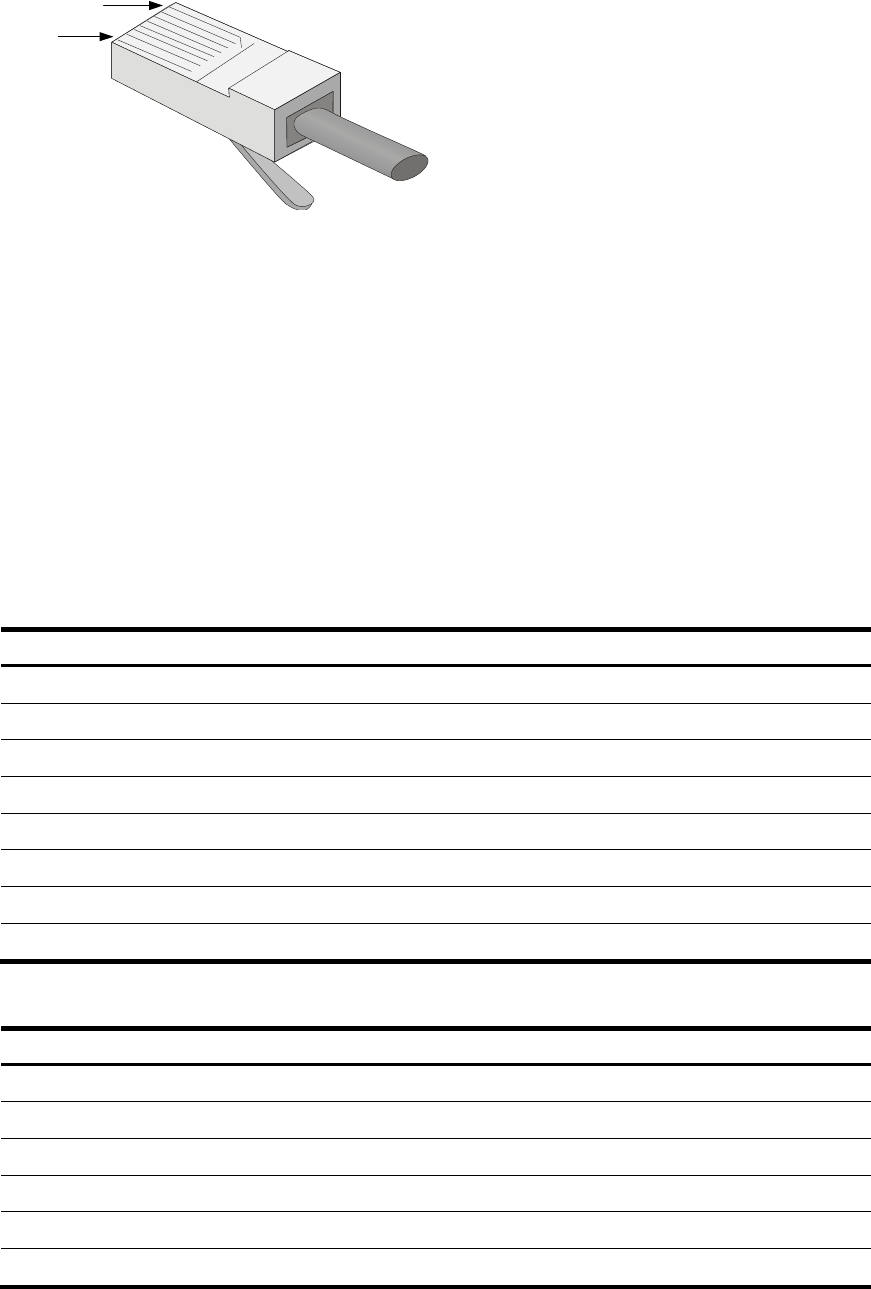
Connecting the AUX cable ············································································································································ 18
Overview ································································································································································ 18
Connecting the AUX cable ··································································································································· 18
Connecting an Ethernet cable······································································································································· 19
Overview ································································································································································ 19
Making an Ethernet cable ···································································································································· 21
Connecting an Ethernet cable ······························································································································ 21
Connecting a fiber cable ·············································································································································· 21
Transceiver module overview ······························································································································· 21
Fiber cable overview ············································································································································· 22
Connecting a fiber cable ······································································································································ 24
Connecting an E1/T1 cable ········································································································································· 25
E1/T1 cable overview ·········································································································································· 25
ii
Connecting an E1/T1 cable ································································································································ 26
Connecting a CE3/CT3 cable ····································································································································· 28
CE3/CT3 cable overview ···································································································································· 28
Connecting a CE3/CT3 cable ····························································································································· 28
Connecting a serial port cable ····································································································································· 29
Overview ································································································································································ 29
Connecting a serial port cable ···························································································································· 31
Logging in to the router and configuring basic settings ·························································································· 33
Login methods ································································································································································· 33
Logging in through the console port ···························································································································· 33
Preparation ····························································································································································· 33
Setting up a configuration environment ·············································································································· 33
Setting terminal parameters ·································································································································· 34
Verification before power-on ······························································································································· 37
Powering on the router ········································································································································· 37
Logging in to the router through Telnet/SSH ·············································································································· 38
Logging in to the router through the AUX port ············································································································ 38
Displaying the initial configuration ······························································································································ 39
Configuring basic settings ············································································································································· 39
Replacement procedures ··········································································································································· 41
Safety recommendations ··············································································································································· 41
Replacing a power module ··········································································································································· 41
Replacing a FIP module ················································································································································· 42
Replacing a HIM/MIM ·················································································································································· 42
Replacing a CF card ······················································································································································ 43
Replacing a transceiver module ··································································································································· 44
Replacing a fan tray ······················································································································································ 45
Replacing a memory module ········································································································································ 46
Memory module structure ····································································································································· 47
When to replace a memory module ··················································································································· 47
Replacing a memory module ······························································································································· 47
Hardware management and maintenance ·············································································································· 49
Displaying hardware information of the router ··········································································································· 49
Displaying the software and hardware version information of the router······················································· 49
Displaying the operational statistics of the router ······························································································ 50
Displaying the detailed information about a module ························································································ 50
Displaying the electrical label information of a module ··················································································· 51
Displaying the CPU usage of a module ·············································································································· 52
Displaying the memory usage of a module ········································································································ 52
Displaying the CF card information ···················································································································· 53
Displaying the operational status of the built-in fan ··························································································· 53
Displaying the operational status of power modules························································································· 54
Displaying the alarming thresholds of a module ········································································································ 54
Configuring a combo interface ···································································································································· 54
Combo interface overview ··································································································································· 54
Configuration prerequisites ·································································································································· 54
Configuring a combo interface ···························································································································· 56
Displaying transceiver module information and alarming information ···································································· 56
Introduction to transceiver modules ····················································································································· 56
Displaying transceiver module information ········································································································ 56
Displaying the alarming information or fault detection parameters for a transceiver module ······················ 57
Solving system faults ······················································································································································ 57
Solving system faults ············································································································································· 57
iii
Viewing the system fault solving method ············································································································ 58
Saving the current configuration of the router ············································································································ 58
Rebooting the router ······················································································································································ 58
Troubleshooting ·························································································································································· 60
Router failures ································································································································································· 60
Power status LEDs are off ······································································································································ 60
RUN LED is off ······················································································································································· 60
RUN LED fast flashes ············································································································································· 60
ALM LED is steady on or flashes ·························································································································· 60
FIP module failure ··························································································································································· 61
Power module failures ··················································································································································· 61
Fan failures ····································································································································································· 62
Fan tray is absent ·················································································································································· 62
ALM LED is red ······················································································································································ 63
HIM/MIM failures ·························································································································································· 63
Configuration system problems ···································································································································· 63
No terminal display ·············································································································································· 63
Garbled terminal display ······································································································································ 64
No response from the serial port ························································································································· 64
Dealing with password loss ·········································································································································· 64
Examining the state of password recovery capability ······················································································· 65
Dealing with console login password loss when password recovery capability is enabled ························ 66
Dealing with user privilege level password loss when password recovery capability is enabled ··············· 67
Dealing with password loss when password recovery capability is disabled ··············································· 68
Cooling system failure ··················································································································································· 69
Interface module, cable, and connection failure ········································································································ 70
Software upgrade failures ············································································································································· 70
No response from the serial port ························································································································· 70
TFTP upgrade failure ············································································································································· 70
FTP upgrade failure ··············································································································································· 71
Application file missing errors ······································································································································ 71
Appendix A Chassis views and Technical specifications ······················································································· 73
Chassis views ································································································································································· 73
Dimensions and weights ················································································································································ 74
Storage media ································································································································································ 75
Power consumption ························································································································································ 75
Power module ································································································································································· 75
AC power module ················································································································································· 75
DC power module ················································································································································· 76
Fan tray ··········································································································································································· 77
Port specifications ·························································································································································· 78
Ports and slots ························································································································································ 78
Console port ·························································································································································· 78
AUX port ································································································································································· 78
Management Ethernet port ··································································································································· 79
Combo interface ···················································································································································· 79
10 Gbps Ethernet port ·········································································································································· 80
Flexible interface platform modules ····························································································································· 81
FIP-10 ······································································································································································ 81
FIP-20 ······································································································································································ 82
Interface modules ··························································································································································· 83
Appendix B LEDs ························································································································································ 84
Panel LEDs ······································································································································································· 84
iv
HSR6602-G/HSR6602-G TAA panel LEDs ········································································································ 84
HSR6602-XG/HSR6602-XG TAA panel LEDs ··································································································· 85
FIP LEDs ··········································································································································································· 87
HIM/MIM LEDs ······························································································································································ 88
Power module LEDs ························································································································································ 88
Appendix C Cable management ······························································································································ 89
General cabling requirements ······································································································································ 89
Minimum curvature radius of cables ··················································································································· 89
Minimum curvature radius of fibers ····················································································································· 89
Labeling cables······························································································································································· 89
Cable management guidelines ····································································································································· 90
Cable routing example ·················································································································································· 92
Appendix D Arranging slots and numbering interfaces ·························································································· 94
Slot arrangement ···························································································································································· 94
Slot arrangement for FIPs ·············································································································································· 94
Numbering interfaces ···················································································································································· 95
Examples ········································································································································································· 95
Example 1 ······························································································································································ 95
Example 2 ······························································································································································ 95
Support and other resources ····································································································································· 97
Contacting HP ································································································································································ 97
Subscription service ·············································································································································· 97
Related information ························································································································································ 97
Documents ······························································································································································ 97
Websites ································································································································································· 97
Conventions ···································································································································································· 98
Index ········································································································································································ 100
1
Preparing for installation
The HP HSR6600 Router Series is a line of high-performance centralized product, which includes the
models in Table 1.
Table 1 Models for the HP HSR6600 Routers
Product code Full name RMN
Abbreviation
JG353A HP HSR6602-G Router BJNGA-BB0001 HSR6602-G
JG354A HP HSR6602-XG Router BJNGA-BB0001 HSR6602-XG
JG776A HP HSR6602-G TAA Router BJNGA-BB0001 HSR6602-G TAA
JG777A HP HSR6602-XG TAA Router BJNGA-BB0001 HSR6602-XG TAA
JG357A RT-FIP-10 FIP-10 FIP-10
JG358A RT-FIP-20 FIP-20 FIP-20
IMPORTANT:
For regulatory identification purposes, every HSR6600 Router is assigned a regulatory model
number(RMN). These re
g
ulatory numbers should not be confused with the marketin
g
name HP HSR6600,
or product codes.
Safety recommendations
Safety symbols
When reading this document, note the following symbols:
WARNING means an alert that calls attention to important information that if not understood or
followed can result in personal injury.
CAUTION means an alert that calls attention to important information that if not understood or
followed can result in data loss, data corruption, or damage to hardware or software.
General safety recommendations
• Make sure that the ground is dry and flat and anti-slip measures are in place.
• Keep the chassis and installation tools away from walk areas.
• Make sure the installation site is well grounded, and lightning protection and ESD-prevention are
provided.
• Only trained and qualified personnel are allowed to install or service the router.
• Keep accessories, installation tools, and documentation safe.
• Avoid bodily injury. Do not touch any power plug when it is connected.
• Clean up the packaging materials after installation to avoid fire hazard.

2
Electricity
• Locate the emergency power-off switch in the room before installation. Shut the power off at once in
case accident occurs.
• Make sure that the router has been correctly grounded.
• Use an uninterrupted power supply (UPS).
• If there are two power inputs, disconnect the two power inputs to power off the router.
• Do not work alone when the router has power.
• Always check that the power has been disconnected.
Laser safety
The HP HSR6600 routers are Class 1 laser devices.
W
ARNING!
• Do not stare into any fiber port when the router has power. The laser li
g
ht emitted from the optical fiber
may hurt your eyes.
• Use a fiber test equipment, rather than a microscope or magnifier to observe an operatin
g
fiber or por
t
when you test link connectivity or system parameters.
Router moving
When you move an HSR6600 router, follow these guidelines:
• Move and unpack the router carefully to avoid router damage.
• Use a safety hand truck when you move a heavy device or multiple devices.
• Before you move the router, remove all the cables, USB devices, mounting brackets, and cable
management brackets.
• If the router needs to be moved over a long distance, remove all the field-replaceable units (FRUs),
such as power modules, fan trays, and interface modules, and package them separately, and install
the filler panels supplied with router.
• If the router needs to be moved over a short distance, make sure all the FRUs are securely seated in
slot and the screws are fastened.
• When you move or lift the router chassis, support the bottom of the chassis, rather than holding any
FRU. Make sure the accessories of the router are not lost or damaged during router moving.
Examining the installation site
Weight support
Evaluate the floor loading as compared to the actual weight of the router and its accessories (such as
rack and power modules), and make sure that the floor can support the weight of the rack and the router
chassis. For more information, see “Appendix A Chassis views and Technical specifications.”

3
Temperature and humidity
Maintain appropriate temperature and humidity in the equipment room.
• Lasting high relative humidity can cause poor insulation, electricity creepage, mechanical property
change of materials, and metal corrosion.
• Lasting low relative humidity can cause washer contraction and ESD and bring problems including
loose captive screws and circuit failure.
• High temperature can accelerate the aging of insulation materials and significantly lower the
reliability and lifespan of the router.
For the temperature and humidity requirements of the router, see Table 2.
Table 2 Temperature requirements
Item Tem
p
erature
Operating temperature 0°C to 45°C (32°F to 113°F)
Storage temperature –40°C to 70°C (–40°F to +158°F)
Table 3 Humidity requirements
Item Relative humidit
y
Operating humidity 5% to 95%
Storage humidity 5% to 95%
Altitude
Table 4 Altitude requirements
Item Altitude
Operating altitude –60 m (–196.85 ft) to 4 km (2.49 miles)
Storage altitude –60 m (–196.85 ft) to 4.5 km(2.8 miles)
Cleanness
Dust buildup on the chassis may result in electrostatic adsorption, which causes poor contact of metal
components and contact points, especially when indoor relative humidity is low. In the worst case,
electrostatic adsorption can cause communication failure.
Table 5 Dust concentration limit in the equipment room
Substance Concentration limit (
p
articles/cu m)
Dust particles 3 x 10⁴
(No visible dust on desk in three days)
NOTE:
Dust particle diameter ≥ 5 μm
4
The equipment room must also meet strict limits on salts, acids, and sulfides to eliminate corrosion and
premature aging of components, as shown in Table 6.
Table 6 Harmful gas limits in an equipment room
Gas Max. (m
g
/m3)
SO2 0.2
H2S 0.006
NH3 0.05
Cl2 0.01
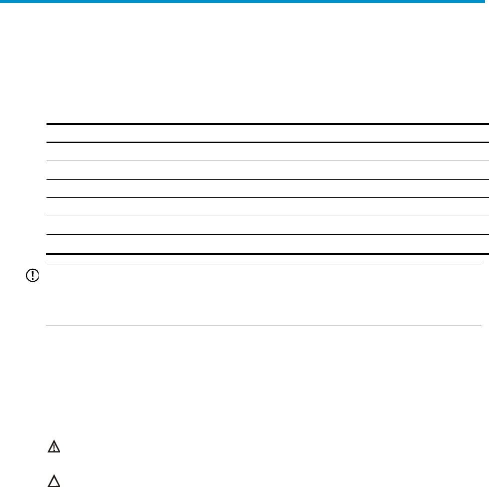
Cooling system
The HSR6600 routers adopt left to right airflow for heat dissipation.
Figure 1 Airflow
• Make sure there is enough space (greater than 10 cm (3.94 in)) around the air intake and outlet
vents on the router for good ventilation.
• Make sure the installation site has a good cooling system.
ESD prevention
To prevent electrostatic discharge (ESD), note the following guidelines:
• Make sure that the router and rack are well grounded.
• An anti-static floor is installed and well grounded.
• Maintain the humidity and temperature at a proper level in the equipment room. For more
information, see “Temperature and humidity.”
• Always wear an ESD-preventive wrist strap and ESD-preventive cloth when touching a circuit board,
interface module, or transceiver module.
• Place the removed memory module, CF card, FIP, HIM, or MIM on an antistatic workbench, with the
face upward, or put it into an antistatic bag.
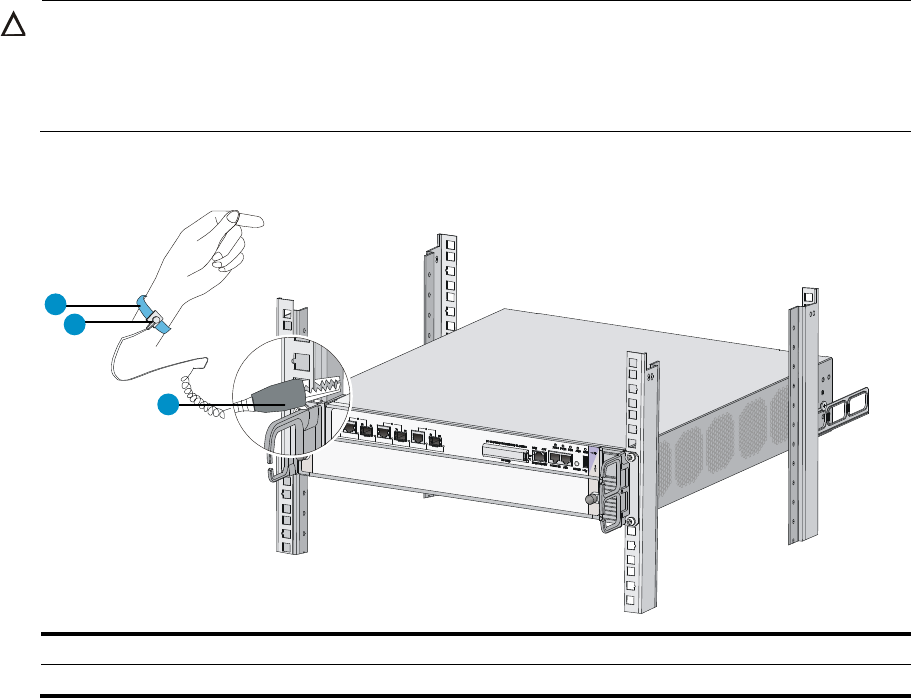
5
• Touch only the edges, instead of electronic components when observing or moving a removed
memory module, CF card, HIM, or MIM.
To use the ESD-preventive wrist strap, perform the following steps:
1. Wear the wrist strap on your wrist.
2. Lock the wrist strap tight around your wrist to keep good contact with the skin.
3. Attach the ESD-preventive wrist strap to the alligator clips.
4. Attach the alligator clips to the rack post.
5. Make sure that the rack is well grounded.
CAUTION:
• Check the resistance of the ESD-preventive wrist strap for safety. The resistance readin
g
should be in the
range of 1 to 10 megohm (Mohm) between human body and the ground.
• The HSR6600 does not provide any ESD-preventive wrist strap. Prepare it yourself.
Figure 2 Use an ESD-preventive wrist strap
(1) ESD-preventive wrist strap (2) Lock
(3) Alli
g
ator clip
EMI
All electromagnetic interference (EMI) sources, from outside or inside of the router and application system,
adversely affect the router in a conduction pattern of capacitance coupling, inductance coupling,
electromagnetic wave radiation, or common impedance (including grounding system) coupling. To
prevent EMI, perform the following tasks:
• Take measures against interference from the power grid.
• Do not use the router together with the grounding equipment or light-prevention equipment of
power equipment, and keep the router far away from them.
• Keep the router far away from high-power radio launchers, radars, and equipment with high
frequency or high current.
12
3

6
NOTE:
Use electromagnetic shielding when necessary.
Lightning protection
To protect the router from lightning better, do as follows:
• Make sure the chassis is well grounded.
• Make sure the grounding terminal of the AC power receptacle is well grounded.
• Install a lightning protector at the input end of the power supply to enhance lightning protection
capability.
• Install a surge lightning protector at the input end of outdoor signal lines (for example, E1/T1 line)
to which interface modules of the router are connected to enhance the lightning protection
capability.
Space
• For ease of installation and maintenance, make sure that the front and rear clearances are at least
1 m (3.28 ft).
• For heat dissipation, make sure the headroom in the equipment room is no less than 3 m (9.84 ft),
and an appropriately sized air conditioner is provided.
Power supply
Perform the following steps to satisfy the power supply requirements of the HSR6600 routers:
1. Calculate the system power consumption.
The system power consumption of the HSR6600 routers depends on the number and type of
interface modules, and fan tray power consumption. For the power consumption of the router, see
“Appendix A Chassis views and Technical specifications.”
2. Select power modules according to the system power consumption.
To ensure normal operation of the router, make sure the maximum output power of the power
modules is greater than the system power consumption of the router. After determining the system
power consumption, you can select power modules as needed. For power module specifications,
see “Appendix A Chassis views and Technical specifications.”
3. Check that the power source on the installation site satisfies the power input of the power modules.
Make sure the power source of the installation site is steady and can satisfy the input requirements
of the power modules and parameters such as rated voltage.
7
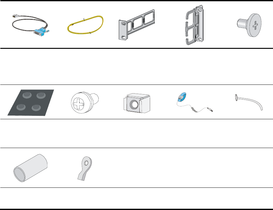
Accessories
Console cable
(supplied with router)
3 m (9.84 ft)
grounding cable
(supplied with
router)
Rear mounting
bracket
(supplied with
router)
Front mounting
bracket and cable
management bracket
(supplied with router)
Load-bearing
screw
(supplied with
router)
Rubber feet
(supplied with router)
M6 screw
(user-supplied)
Cage nuts
(user-supplied)
ESD-preventive wrist
strap
(user-supplied)
Cable tie
(user-supplied)
Insulation sheath
(user-supplied)
Ring terminal
(user-supplied)
8
Installing the router
NOTE:
The fan tray, power modules, FIPs, and interface modules are hot swappable.
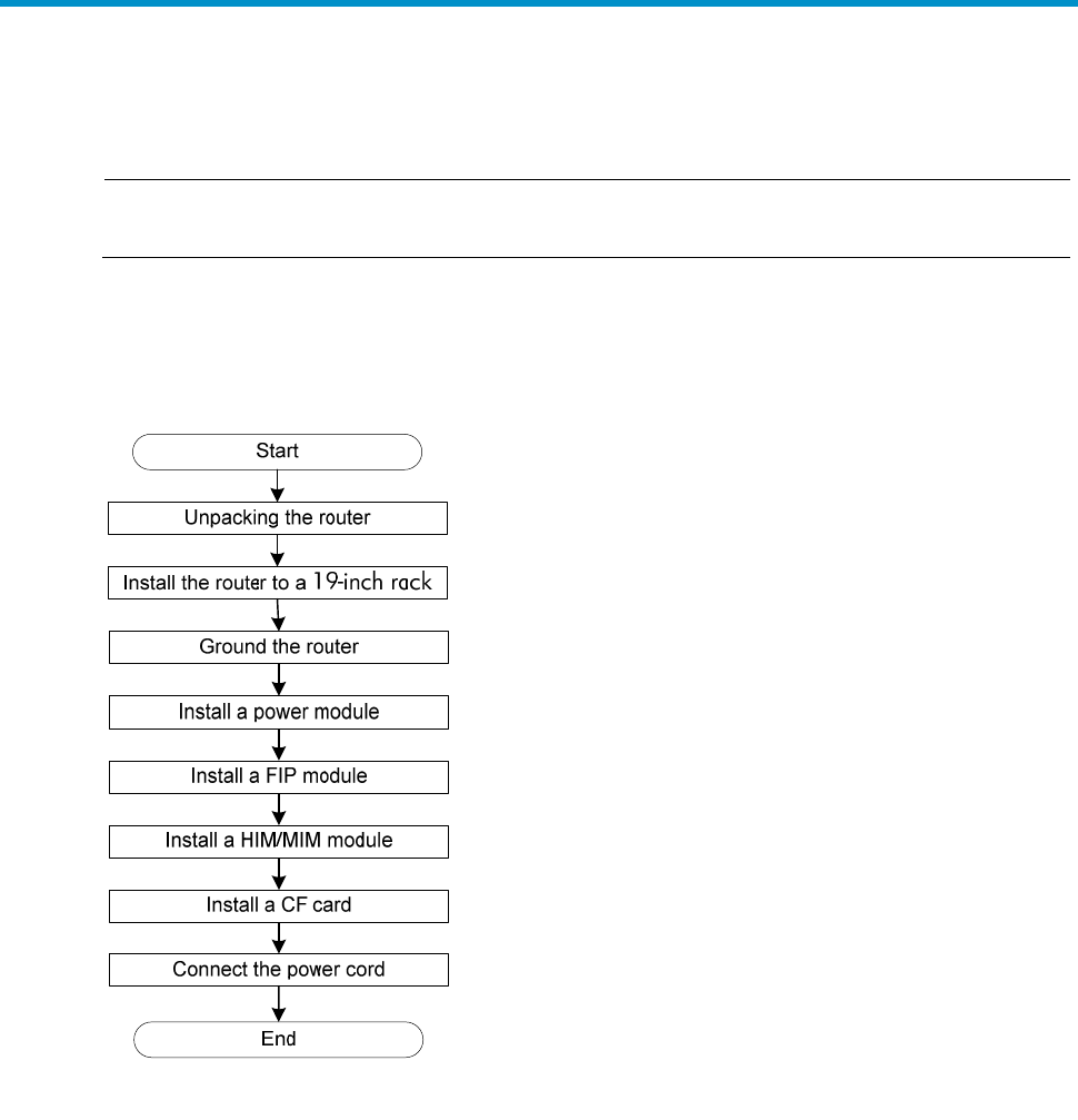
Installation flow
Figure 3 HSR6600 installation flow
Check before installation
Follow these guidelines to prepare for installing an HSR6600 router:
• Make sure that you have read “Preparing for installation” carefully and the installation site meets all
the requirements.
• Prepare a 19-inch rack.
• Make sure that the rack is sturdy and securely grounded.
• Make sure that there is sufficient clearance around the rack for heat dissipation and installation.
• Make sure that there is no debris inside or around the rack.
• Move the router to a place near the rack.
9
IMPORTANT:
To mount multiple devices in the rack, place the heaviest one at the bottom of the rack.
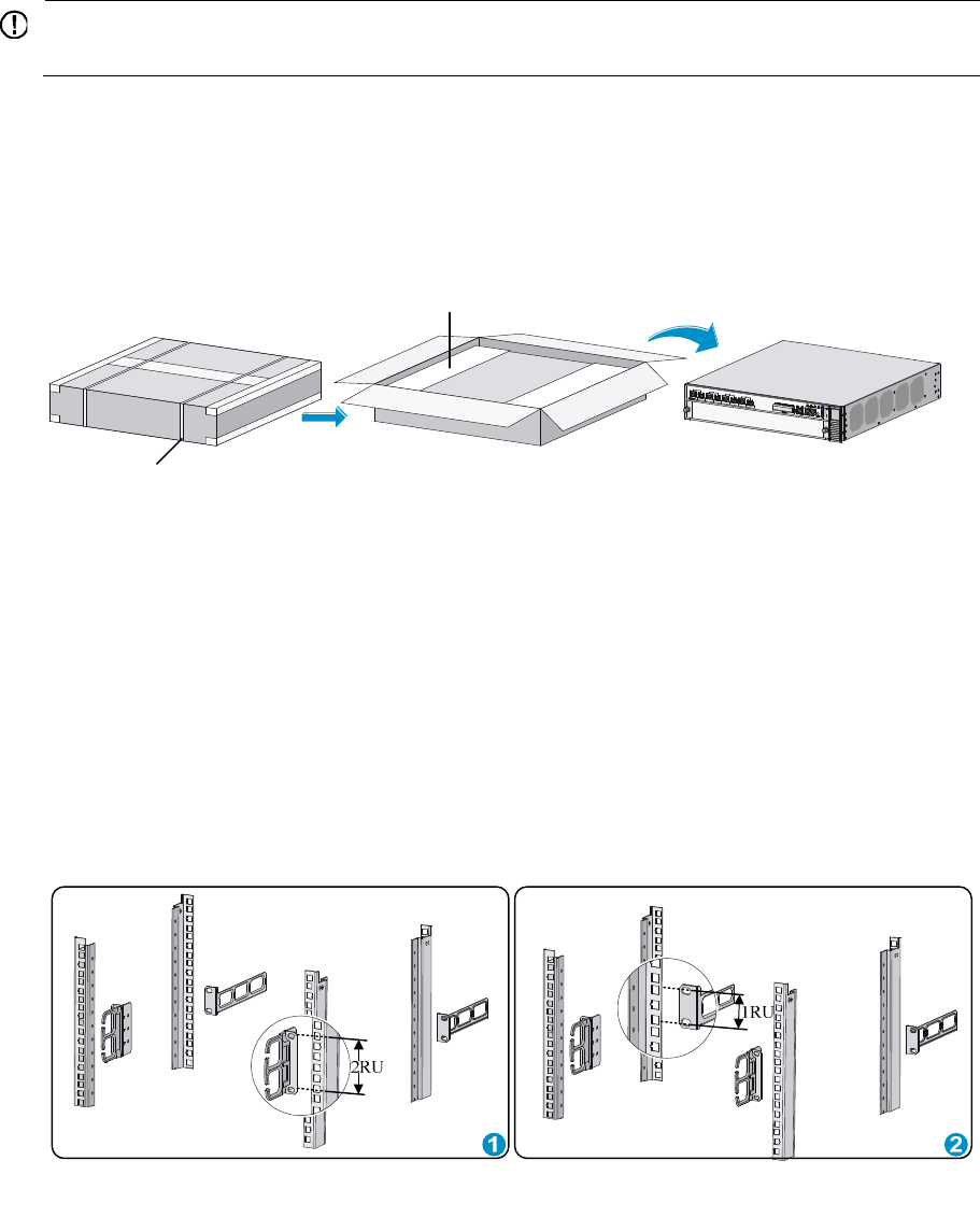
Unpacking the router
Unpack the router as shown in Figure 4.
Figure 4 Unpacking the router
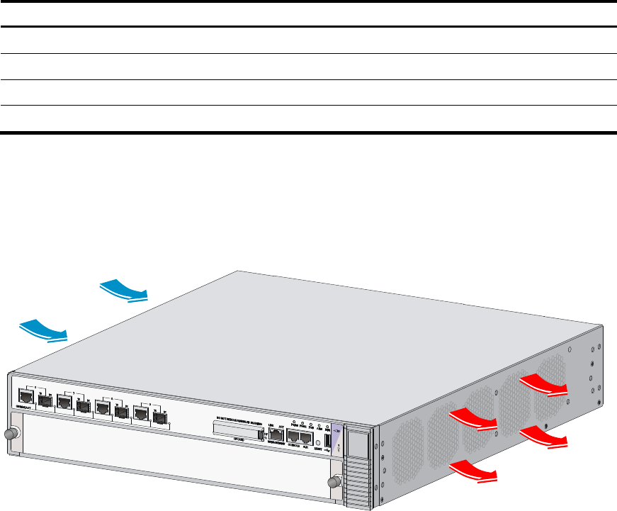
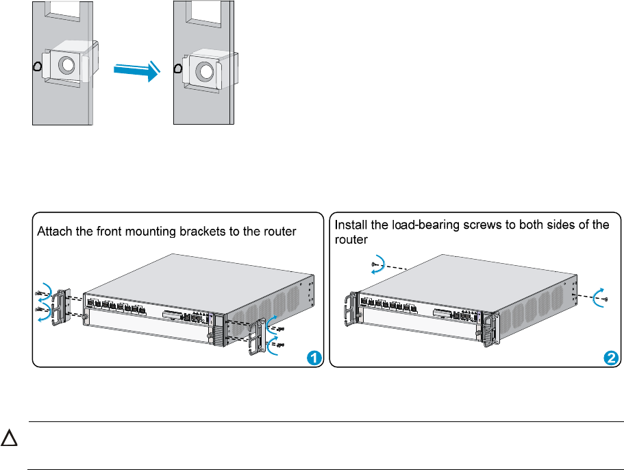
Installing the router in a 19-inch rack
Before you install the router to a rack, wear an ESD-preventive wrist strap. For how to wear an
ESD-preventive wrist strap, see “ESD prevention.” The HSR6600 Routers are installed in the same way.
The HSR6602-G is used as an example in this section.
To install the router in a rack:
1. Mark the positions of cage nuts on the front rack posts by using a front mounting bracket and mark
the positions of cage nuts on the rear rack posts by using a rear mounting bracket. See Figure 5.
Figure 5 Marking the positions of the cage nuts
2. Insert one edge of a cage nut into the hole, and use a flat-blade screwdriver to compress the other
edge of the cage nut to push the cage nut fully into the hole.
Packing belt
Foam brace
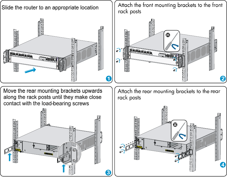
11
Figure 8 Installing the router to the rack
Grounding the router
Installing the ring terminal
No ring terminal is supplied with the grounding cable. You must install one yourself.
To install the ring terminal:
1. Cut the grounding cable as appropriate for connecting to the grounding strip, and strip 5 mm
(0.20 in) of insulation sheath by using a wire stripper.
2. Insert the bare metal part through the black insulation covering into the end of the ring terminal.
3. Crimp the metal part of the cable to the ring terminal with a crimper.
4. Cover the joint with the insulation covering, and heat the insulation covering with a blow dryer to
completely cover the metal part.
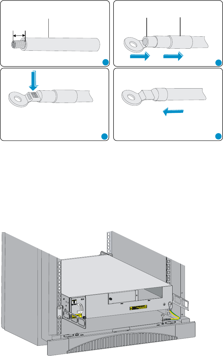
12
Figure 9 Installing the ring terminal
Connecting the grounding cable
1. Remove the grounding screw from the rear panel of the router chassis.
2. Attach the grounding screw to the ring terminal of the grounding cable.
3. Use a screwdriver to fasten the grounding screw into the grounding screw hole.
4. Attach the ring terminal on the other end of the grounding cable to the grounding strip.
Figure 10 Connecting the grounding cable
Insulation sheathRing terminal
12
34
Grounding cable
5mm
13
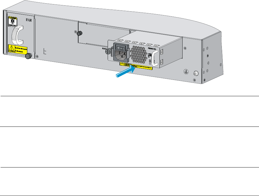
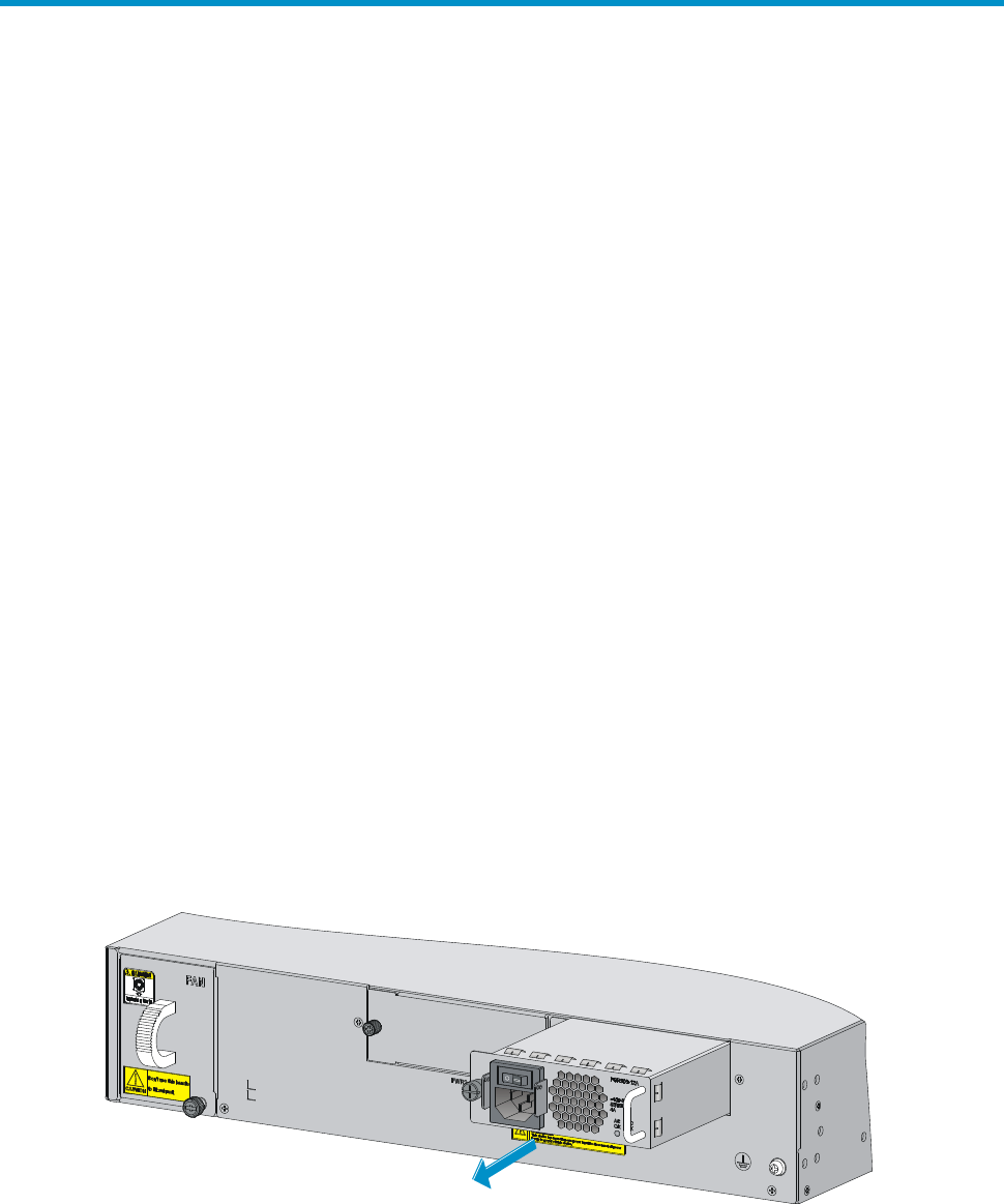
Installing a power module
Before you install a power module, make sure the power switch is off and the router is well grounded. The
procedures for installing an AC power module and a DC power module are the same. The following uses
an AC power module as an example.
1. Locate the slot to install the power module.
{ To install the power module to slot PWR1, go to step 2.
{ To install the power module to slot PWR2, use a Phillips screwdriver to remove the filler panel
from the slot first. Keep the filler panel safe for future use.
2. Correctly orient the power module with the power module slot (see Figure 11), grasp the handle of
the power module with one hand and support its bottom with the other, and slide the power
module slowly along the guide rails into the slot.
3. Fasten the captive screws on the power module with a Phillips screwdriver.
Figure 11 Installing the power module
NOTE:
• For the power module LED description, see “Appendix B LEDs.”
• An AC power module and a DC power module cannot be installed on the same router.
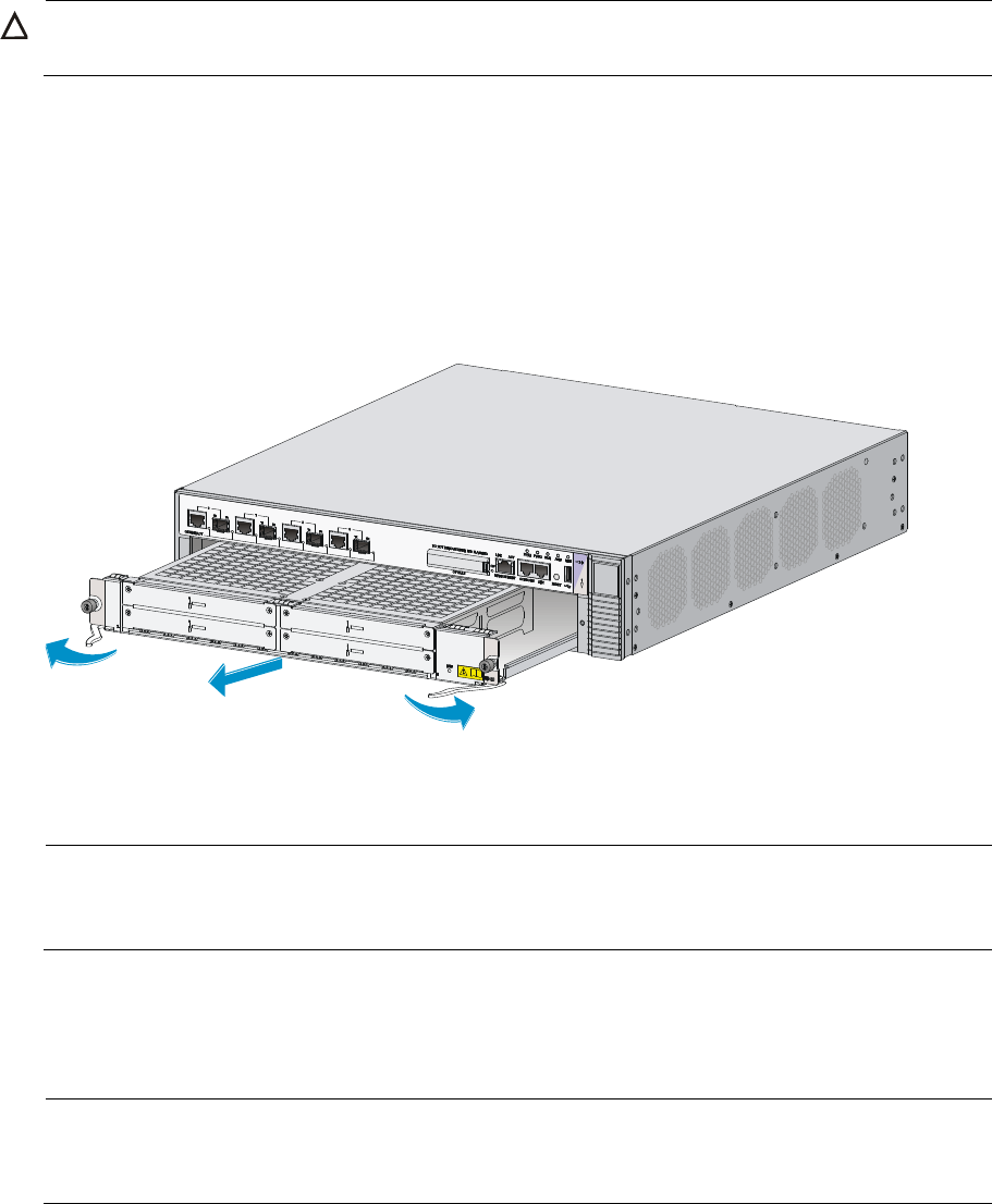
Installing a FIP module
NOTE:
Before you install a FIP module, make sure that the ejector levers are in the open position away from the
FIP module panel.
The following uses a FIP-20 as an example.
1. Locate the slot to install the FIP module, and remove the filler panel.
2. Use a Phillips screwdriver to loosen the captive screws on the filler panel, and remove the filler
panel. Keep the filler panel safe for future use.
3. Use even pressure to gently push the FIP module into the slot along the slide rails until positioning
pins on the backplane are seated in the positioning holes, and then push the ejector levers inward
to lock the FIP module in position.
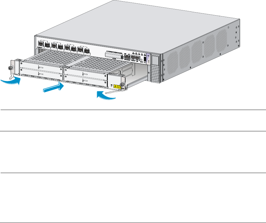
14
4. Fasten the captive screws on the FIP module with a Philips screwdriver.
Figure 12 Installing a FIP module
NOTE:
For more information about the FIP LEDs, see “Appendix B LEDs.”
Installing a HIM/MIM
NOTE:
• Install the MIM in the lower slot on the FIP module.
• Only the FIP-20 supports HIMs.
• Before you install a HIM, make sure that the ejector levers are in the open position away from the HIM
module panel.
The procedures for installing HIMs and MIMs are similar. This example installs a MIM to a FIP-20.
To install a MIM:
1. Locate the slot to install the MIM on the FIP module.
2. Loosen the captive screws on a filler panel with a Phillips screwdriver, and then use a flat-blade
screwdriver to prize the filler panel to remove it from the router. Keep the filler panel safe for future
use.
3. Use even pressure to push the MIM slowly along the slide rails into the slot, and then pull the levers
inward.
4. Use a flat-blade screwdriver to fasten the captive screws on the MIM.
15
Figure 13 Installing the MIM
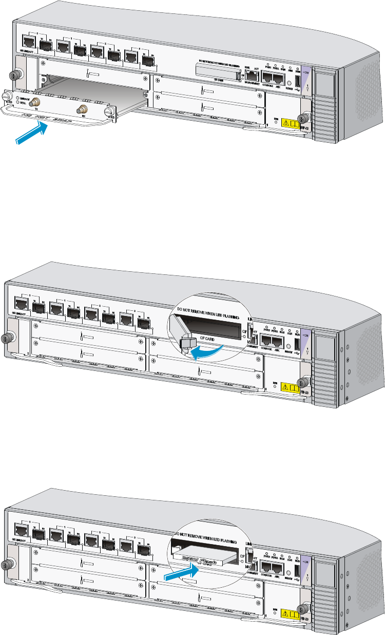
Installing a CF card
1. Press the spring clip at the right of the CF card cover to open it.
Figure 14 Open the CF card cover
2. Press the ejector button next to the CF card slot. Insert the CF card into the slot and make sure it
does not project from the slot.
Figure 15 Insert the CF card
3. Close the CF card cover.
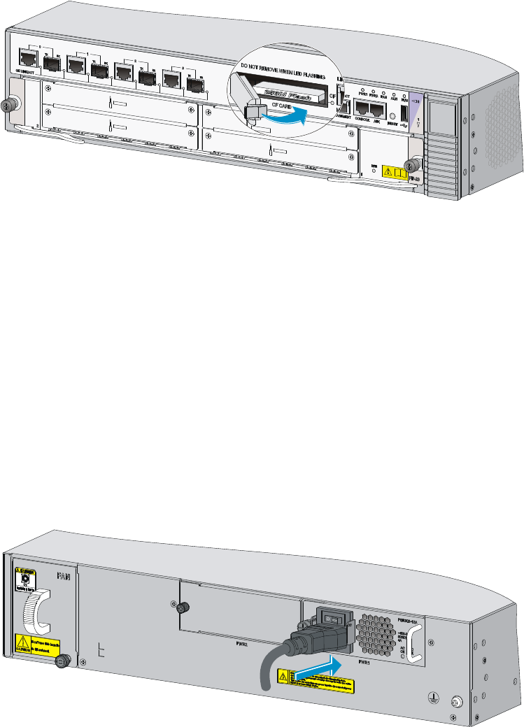
16
Figure 16 Close the CF card cover
Connecting the power cord
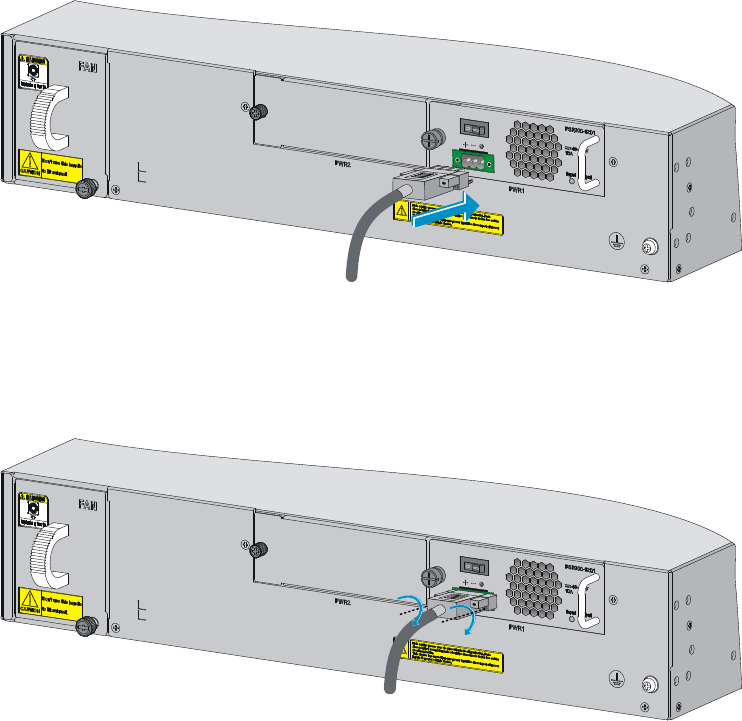
Connecting an AC power cord
To connect an AC power cord:
1. Make sure the router is well grounded, and the power switch on the router is in the OFF position.
2. Pull the bail latch upwards.
3. Connect one end of the AC power cord to the AC-input power receptacle on the router.
4. Pull the bail latch down to secure the plug to the power receptacle.
5. Connect the other end of the power cord to the AC power outlet.
Figure 17 Connecting an AC power cord to the router
Connecting a DC power cord
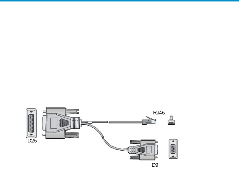
To connect a DC power cord:
1. Correctly orient the plug at one end of the cable with the power receptacle on the power module,
and insert the plug into the power receptacle.
The power receptacle is foolproof. If you cannot insert the plug into the receptacle, re-orient the
plug rather than use excessive force to push it in.
17
Figure 18 Insert the plug
2. Tighten the screws on the plug with a flat-blade screwdriver to secure the plug in the power
receptacle.
Figure 19 Tighten the screws
3. Connect the two wires at the other end of the power cord to a DC power source.
18
Connecting the router to the network
Connecting the AUX cable
Overview
An AUX console cable is an 8-core shielded cable, with a crimped RJ-45 connector at one end for
connecting to the AUX port of the router, and DB-25 and DB-9 male connectors at the other end for
connecting to the serial port of the modem.
Figure 20 AUX cable
Connecting the AUX cable
1. Plug the DB-9 or DB-25 male connector at one end of the AUX cable into the serial port of the
modem.
2. Plug the RJ-45 connector of the AUX cable into the AUX port of the router.
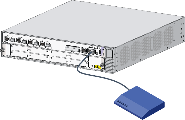
19
Figure 21 Connecting the AUX port to a modem
Connecting an Ethernet cable
Overview
10/100 Mbps Ethernet uses category-5 twisted pair cables, while 1000 Mbps Ethernet uses category-5
enhanced or category-6 twisted pair cables. Twisted pair cables include straight-through cables and
crossover cables.
Category-5 cables provide a transmission frequency of 100 MHz for voice and data transmission; they
are mainly used in 100Base-T and 10Base-T networks. Category-5 cables are common Ethernet cables,
which can also be used to transmit 1000 Mbps Ethernet data.
Category-5 enhanced cables feature low attenuation and crosstalk, providing higher attenuation to
crosstalk ratio (ACR), less delay error and higher performance than category-5 cables. Category-5
enhanced cables are mainly used in 1000 Mbps Ethernet networks.
Category-6 cables provide a transmission frequency of 1 MHz to 250 MHz, and improve the
performance on crosstalk and return loss. A fine better return loss performance is extremely important for
new-generation full-duplex high-speed networks. Category-6 cables have sufficient power sum ACR
(PS-ACR) when working at 200 MHz. They provide a bandwidth two times than that of category-5
enhanced cables, thus featuring a higher transmission performance. Therefore, category-6 cables are
suitable for applications requiring a transmission speed of more than 1 Gbps.
The 10/100 Mbps Ethernet uses two pairs of cables, orange/white, orange, green/white and green
cables, to transmit and receive data, while the 1000 Mbps Ethernet uses four pairs of cables to transmit
and receive data.
An Ethernet twisted pair cable connects network devices through the RJ-45 connectors at the two
ends. Figure 22 shows the pinouts of an RJ-45 connector.
20
Figure 22 RJ-45 connector pinout
EIA/TIA cabling specifications define two standards, 568A and 568B, for cable pinouts.
• Standard 568A—Pin 1: white/green stripe, pin 2: green solid, pin 3: white/orange stripe, pin 4:
blue solid, pin 5: white/blue stripe, pin 6: orange solid, pin 7: white/brown stripe, pin 8: brown
solid.
• Standard 568B—Pin 1: white/orange stripe, pin 2: orange solid, pin 3: white/green stripe, pin 4:
blue solid, pin 5: white/blue stripe, pin 6: green solid, pin 7: white/brown stripe, pin 8: brown
solid.
Ethernet twisted pair cables can be classified into straight-through and crossover cables based on their
pinouts
For the pinouts of the twisted pair cables, see the following tables. (A and B represent the two ends of a
cable, respectively.)
Table 7 Straight-through cable pinouts
Pinout No. A B
1 Orange/white Orange/white
2 Orange Orange
3 Green/white Green/white
4 Blue Blue
5 Blue/white Blue/white
6 Green Green
7 Brown/white Brown/white
8 Brown Brown
Table 8 Crossover cable pinouts
Pinout No. A B
1 Orange/white Green/white
2 Orange Green
3 Green/white Orange/white
4 Blue Blue
5 Blue/white Blue/white
6 Green Orange
PIN #8
PIN #1

21
Pinout No. A B
7 Brown/white Brown/white
8 Brown Brown
NOTE:
Strictly follow the pinouts in the above tables when identifyin
g
or makin
g
the two types of Ethernet cables;
otherwise, the communication quality may be affected.
Making an Ethernet cable
To make an Ethernet twisted pair cable:
1. Cut the cable to a proper length with the crimping pliers.
2. Strip off an appropriate length of the cable sheath. The length is typically that of the RJ-45
connector.
3. Untwist the pairs so that they can lay flat, and arrange the colored wires based on the wiring
specifications.
4. Cut the top of the wires even with one another. Insert the wires into the RJ-45 end and make sure
the wires extend to the front of the RJ-45 end and make good contact with the metal contacts in the
RJ-45 end and in the correct order.
5. Crimp the RJ-45 connector with the crimping pliers until you hear a click.
6. Use a cable tester to verify the proper connectivity of the cable.
Connecting an Ethernet cable
1. Plug one end of an Ethernet twisted pair cable into the copper Ethernet port (RJ-45 port) to be
connected on the router and the other end of the cable into the Ethernet port of the peer device. The
10/100/1000Base-T copper ports of the router support MDI/MDI-X auto-sensing. They are
connected to the network through category-5 or above twisted pairs that are equipped with RJ-45
connectors.
2. Check the status LED of the Ethernet ports. For more information about the LED status, see
“Appendix B LEDs.”
Connecting a fiber cable
Transceiver module overview
When you use a fiber port, you need an SFP, XFP, or SFP+ transceiver module and a fiber cable with an
LC connector.
• SFP transceiver module—Applicable to 100/1000 Mbps Ethernet fiber ports and SFP ports on
some HIMs.
• XFP transceiver module—Applicable to XFP ports on the HIM-1EXP.
• SFP+ transceiver module—Applicable to GE SFP+ ports on the HSR6602-XG/HSR6602-XG TAA.
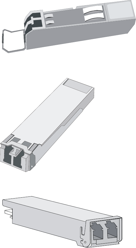
22
Figure 23 SFP transceiver module
Figure 24 XFP transceiver module
Figure 25 SFP+ transceiver module
Fiber cable overview
You can use an optical fiber to connect a fiber Ethernet port or 10 Gbps Ethernet port. In addition, an
optical fiber can connect these types of interface modules: HIM-4GBP/HIM-8GBP, HIM-CL1P/HIM-CL2P,
HIM-CLS1P/HIM-CLS2P, HIM-MSP2P/HIM-MSP4P, HIM-PS1P, HIM-AL1P/HIM-AL2P, HIM-RS2P, or
HIM-1EXP.
Optical fibers feature low loss and long transmission distance.
Optical fibers can be classified into single mode fibers and multi-mode fibers. A single mode fiber
carries only a single ray of light; a multi-mode fiber carries multiple modes of lights.
23
Table 9 Characteristics of single mode and multi-mode optical fibers
Sin
g
le mode fiber
Multi-mode fiber
Core Small core (10 micrometers or less)
Larger core than single mode fiber
(50 micrometers, 62.5
micrometers or greater)
Dispersion Less dispersion
Allows greater dispersion and
therefore, signal loss exists.
Light source and transmission
distance
Users lasers as the light source
often within campus backbones for
distance of several thousand
meters
Uses LEDs as the light source often
within LANs or distances of a
couple hundred meters within a
campus network
Table 10 Allowed maximum tensile force and crush load
Period of force Tensile load (N)
Crush load (N/mm)
Short period 150 500
Long term 80 100
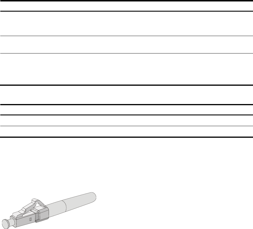
Fiber connectors are indispensable passive components in an optical fiber communication system. They
allow the removable connection between optical channels, which makes the optical system debugging
and maintenance more convenient. There are multiple types of fiber connectors. Figure 26 shows an LC
connector.
Figure 26 Appearance of an LC connector

24
NOTE:
• The HSR6600 supports LC fiber cables only.
• Some cards of the HP HSR6600 router provide shielded covers for the fiber ports (such as SFP ports).
Before using such fiber ports, remove the shielded covers. Keep the shielded covers properly. When the
fiber ports are not in use, install the shielded covers.
• Fiber connectors are fitted with dust caps. Keep the dust caps properly when the fiber connectors are in
use. Install dust caps when the fiber connectors are not in use to avoid damage to their end face. Replace
the dust cap if it is loose or polluted.
• Before connectin
g
an optical fiber, use dust free paper and absolute alcohol to clean the end face of the
two fiber connectors. You can brush the end faces only in one direction.
• After a fiber is installed well, the bend radius must be not less than 10 cm (3.94 in).
• If the fiber has to pass throu
g
h a metallic board hole, the hole must have a sleek and fully filleted surface
(the filleting radius must be not less than 2 mm, or 0.08 in). When passing through a metallic board
hole or bending along the acute side of mechanical parts, the fiber must wear jackets or cushions.
• Insert and remove a plug with care. Never exert a fierce force to the fiber or plug; otherwise the plug
may be damaged or the fiber may be broken. Never pull, press or extrude the fiber fiercely. For the
allowed maximum tensile load and crush load, see Table 10.
Connecting a fiber cable
W
ARNING!
Do not stare into any fiber port when you connect an optical fiber. The laser li
g
ht emitted from the optical
fiber may hurt your eyes.
To connect a fiber cable:
1. Remove the dust plug from a fiber port of the router.
2. Install the transceiver module
3. Identify the Rx and Tx ports. Plug the LC connector at one end of one fiber cable into the Rx port
of the router and the LC connector at the other end into the Tx port of the peer device. Plug the LC
connector at one end of another fiber cable into the Tx port of the router and the LC connector at
the other end to the Rx port of the peer device.
4. View the LINK LED after connection.
{ If the LED is on, the optical fiber link is present.
{ If the LED is off, no link is present. This may be because the TX and Rx port of the optical fiber
are not connected correctly. In this case, connect the optical fiber again.
25
Figure 27 Connecting a fiber cable
Connecting an E1/T1 cable
E1/T1 cable overview
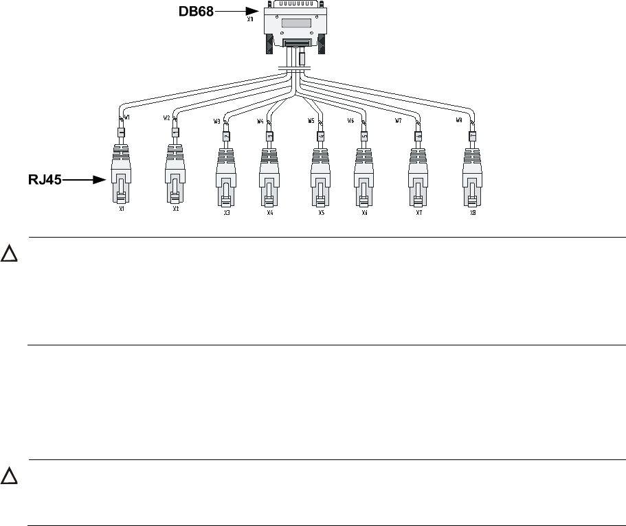
E1 cable
You can use an 8E1 interface cable to connect to MIM-8E1(75)/MIM-8E1(75)-F modules.
Figure 28 8E1 splitter cable
NOTE:
The coaxial connector and 75-ohm E1 adapter cable are optional accessories, and must be purchased
separately if needed.
26
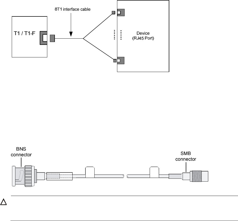
T1 cable
You can use an 8T1 interface cable to connect to MIM-8T1/MIM-8T1-F modules.
Figure 29 8T1 splitter cable
CAUTION:
• When connecting the interface cable, pay attention to the mark on the interface to avoid wrong
insertion, which may damage the interface module or even the router.
• HP recommends that you install a lightning protector at the input end of the 8T1 cables to protect them
against lightning strikes more efficiently when they are led outdoors.
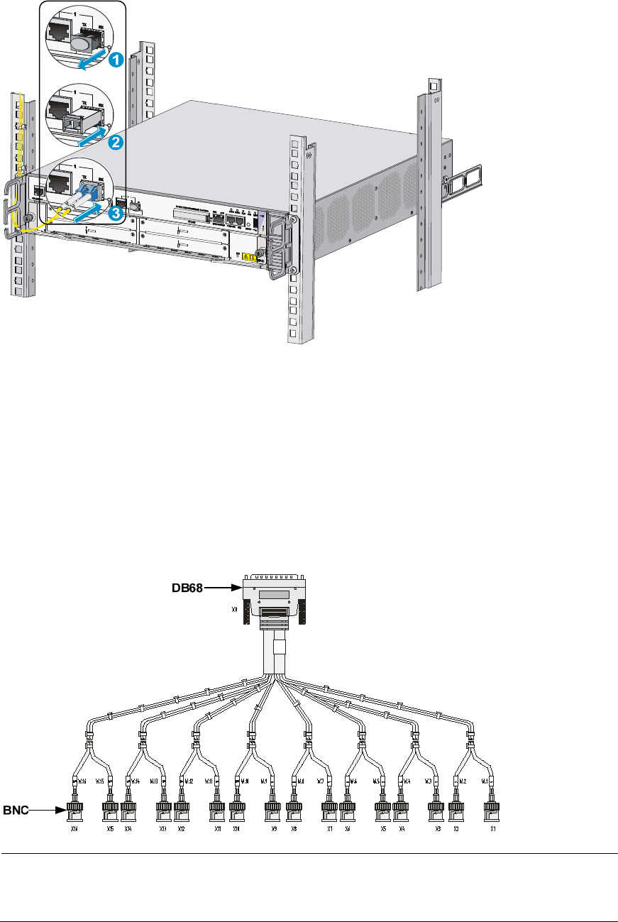
Connecting an E1/T1 cable
Connecting an E1 cable (D15/D68 <----> BNC)
CAUTION:
W
hen connectin
g
the interface cable, pay attention to the mark on the interface to avoid wron
g
insertion,
w
hich may dama
g
e the interface module or even the router.
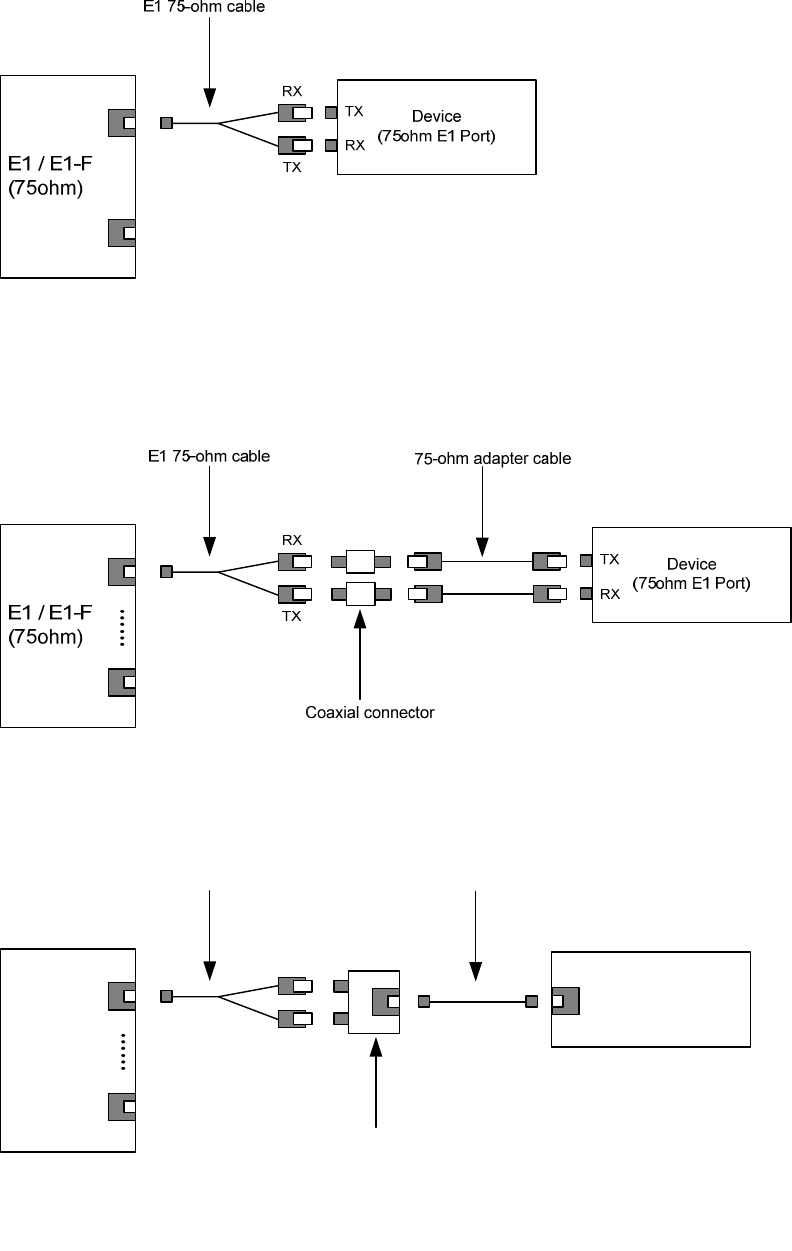
• If you do not need to extend the cable, you can directly connect the BNC connectors of the E1
75-ohm cable to the remote network device as follows.
a. Connect the D15/D68 connector of the E1 75-ohm cable to the D15/D68 interface of the
interface module and fasten the bolts to fix the cable.
b. The other end of the cable provides one pair or multiple pairs of 75-ohm BNC connectors.
Connect the TX connectors and the RX connectors on this end to the RX connectors and the TX
connectors on the remote device respectively.
27
Figure 30 Connect an E1 75-ohm cable
• If you want to extend the cable, connect each BNC connector of the E1 75-ohm cable to one end
of a coaxial connector, and connect the remote device to the other end of the coaxial connector
through an E1 75-ohm adapter cable.
Figure 31 Connect an E1 75-ohm cable
• If the impedance of the E1 interface on the remote device is 120 ohms, you must use an impedance
converter to adapt the impedance.
Figure 32 Connecting an impedance converter
Connecting a T1 cable
1. Connect the D68 connector of the 8-port T1 cable to the D68 interface on the interface module and
fasten the bolts to fix the cable.
……
E1 / E1-F
(75ohm) TX
RX
Device
(120ohm E1 Port)
E1 75-ohm cable Straight-through cable
Impedance converter
28
2. The other end of the cable provides eight RJ-45 connectors. Connect them to the RJ-45 interface on
the remote device as needed.
Figure 33 Connecting an 8T1 cable
Connecting a CE3/CT3 cable
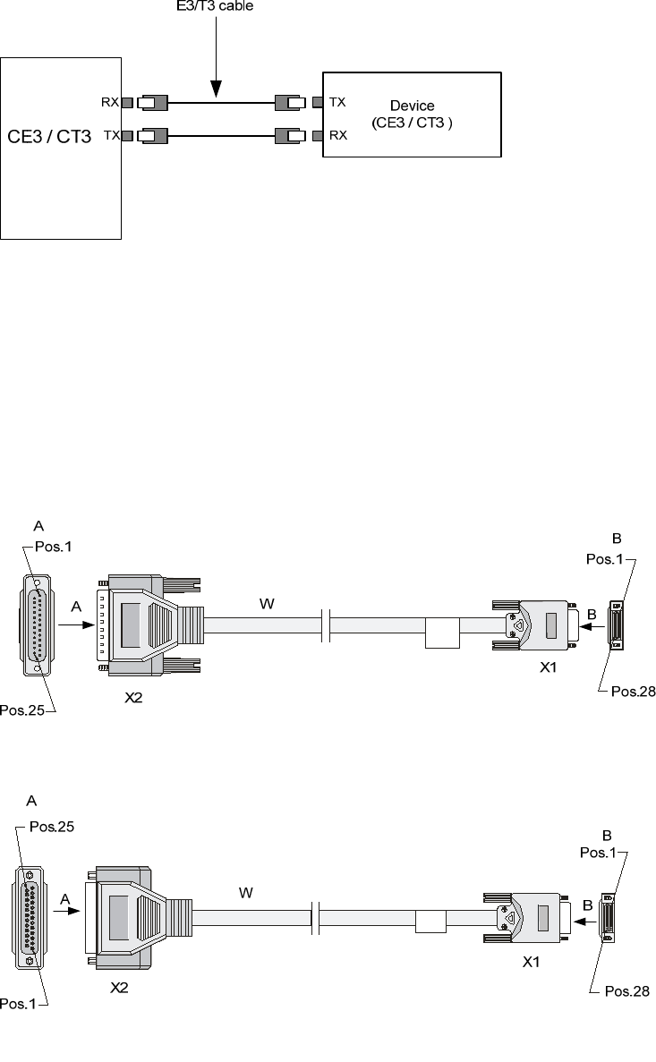
CE3/CT3 cable overview
You can use a CE3/CT3 interface cable to connect the MIM-1CE3 and MIM-1CT3 modules.
Figure 34 E3/T3 cable
CAUTION:
HP recommends that you install a special lightning protector at the input end of the E3/T3 cables to protec
t
them against lightning strikes more efficiently when they are routed outdoors.
Connecting a CE3/CT3 cable
1. Connect the SMB connector of an E3/T3 cable to the Tx port on the interface module and the other
end to the Rx port on the device to be connected.
2. Connect the SMB connector of another E3/T3 cable to the Rx port of interface module and the
other end to the Tx port on the device to be connected
29
Figure 35 Connecting a CE3/CT3 cable
Connecting a serial port cable
Overview
You can use a serial port cable to connect to the MIM-2SAE/MIM-4SAE/MIM-8SAE module. Select a
serial port cable according to the link type.
Figure 36 V.24 DTE cable
Figure 37 V.24 DCE cable
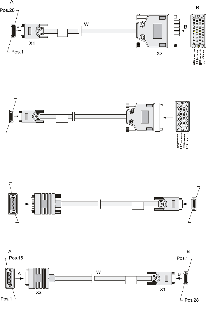
30
Figure 38 V.35 DTE cable
Figure 39 V.35 DCE cable
Figure 40 X.21 DTE cable
Figure 41 X.21 DCE cable
A
A
Pos.28
Pos.1
X1
W
X2
B
B
A
Pos.1
Pos.15
AW
B
Pos.28
X1
Pos.1
B
X2
31
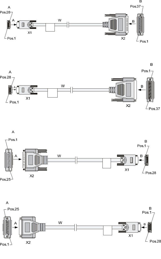
Figure 42 RS449 DTE cable
Figure 43 RS449 DCE cable
Figure 44 RS530 DTE cable
Figure 45 RS530 DCE cable
Connecting a serial port cable
1. Check port type of the peer device and choose the synchronous serial interface cable of correct
type.
2. Plug the D28 end of the synchronous serial interface cable into the D28 interface of the SAE
interface module.
3. If the WAN uses DDN line, connect the cable to the port of the CSU/DSU.
32
4. Check the LINK LED on the SAE panel.
{ If the LED is on, a link is present.
{ If the LED is off, a fault has occurred on the link and signal is out of synchronization. In this case,
check the link.

33
Logging in to the router and configuring basic
settings
Login methods
The following login methods are available for you to log in to the router:
• Logging in through the console port, which is the most common way to log in to a router and also
the prerequisite for configuring other login methods.
• Logging in through Telnet or SSH.
• Logging in through the AUX port.
Logging in through the console port
Preparation
Before you log in to your router, prepare an 8-core shielded cable, with a crimped RJ-45 connector at one
end and a DB-9 male connector at the other end, and a PC with the operating system Windows
95/98/NT/2000/XP/7.
Setting up a configuration environment
To connect a configuration terminal to the router by using the console cable:
1. Select a configuration terminal.
2. Plug the DB-9 female connector to the serial port of the configuration terminal and connect the
RJ-45 connector to the console port of the router.
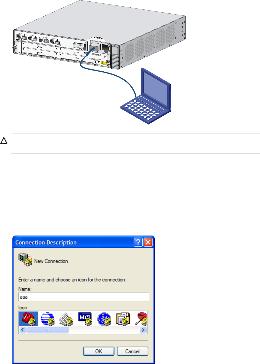
34
Figure 46 Connecting the console cable
CAUTION:
To disconnect a PC from the router, disconnect the RJ-45 connector first.
Setting terminal parameters
To set terminal parameters, for example, on a Windows XP HyperTerminal:
1. Select Start > All Programs > Accessories > Communications > HyperTerminal.
The Connection Description dialog box appears.
2. Enter the name of the new connection in the Name field and click OK.
Figure 47 Connection description for the HyperTerminal
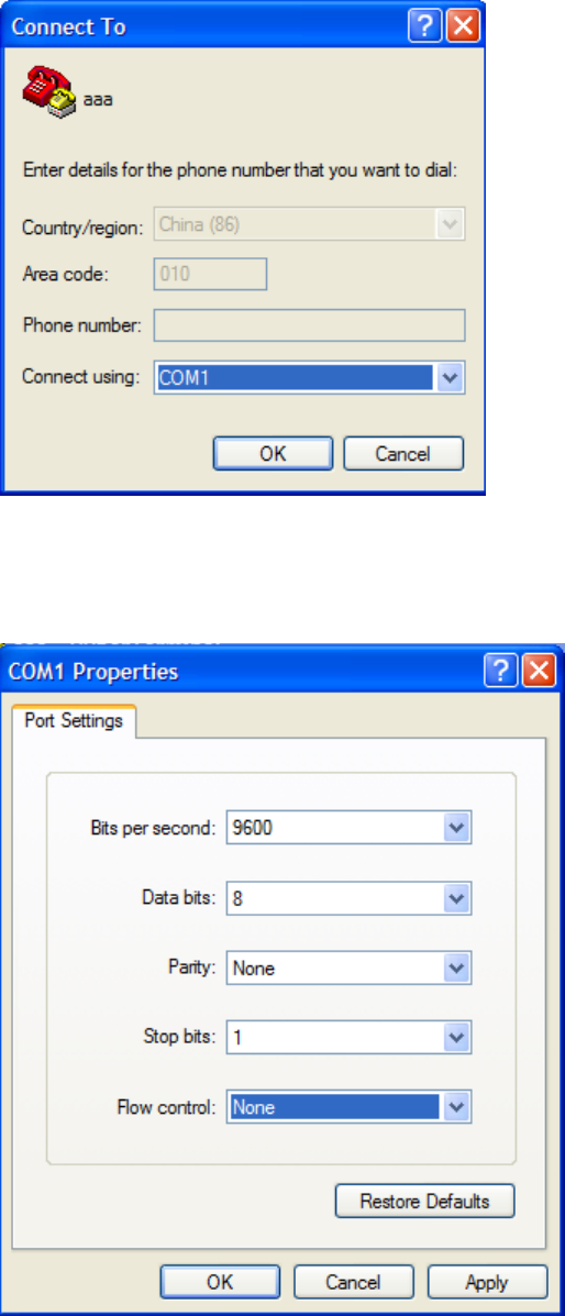
35
3. Select the serial port to be used from the Connect using list, and click OK.
Figure 48 Setting the serial port used by the HyperTerminal connection
4. Set Bits per second to 9600, Data bits to 8, Parity to None, Stop bits to 1, and Flow control to None,
and click OK.
Figure 49 Setting the serial port parameters
5. Select File > Properties in the HyperTerminal window.
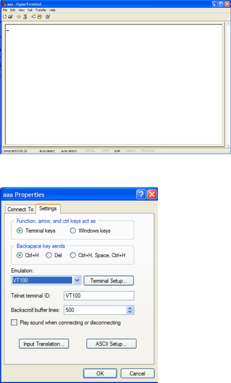
36
Figure 50 HyperTerminal window
6. On the Settings tab, set the emulation to VT100 and click OK.
Figure 51 Setting terminal emulation in aaa Properties dialog box
37
Verification before power-on
Before powering on the router, verify that:
• Make sure the power modules and fan tray are correctly installed.
• The power cord is properly connected.
• The input power voltage meets the requirement of the switch.
• The console cable is properly connected, the terminal or PC used for configuration has started, and
the configuration parameters have been set.
• If you use a CF card, make sure the CF card is firmly seated in slot.
• Make sure the interface modules, if any, are correctly installed.
Powering on the router
Power on the router, and you can see the following information:
System is starting...
Booting Normal Extend BootWare........
****************************************************************************
* *
* HP HSR6600 Router BootWare, Version 1.01 *
* *
****************************************************************************
Copyright (c) 2010-2012 Hewlett-Packard Development Company, L.P.
Compiled Date : Nov 14 2011
CPU Type : P4080
CPU L1 Cache : 32KB
CPU Clock Speed : 1500MHz
Memory Type : DDR3 SDRAM
Memory Size : 4096MB
Memory Speed : 650MHz
BootWare Size : 1024KB
Flash Size : 8MB
Nand Flash size : 512MB
NVRAM Size : 128KB
BASIC CPLD Version : 1.0
EXTEND CPLD Version : 1.0
PCB Version : Ver.A
BootWare Validating...
Press Ctrl+B to enter extended boot menu...
Starting to get the main application file--flash:/HSR6600.bin!
The main application file is self-decompressing.............................
............................................................................

38
............................................................................
......Done!
System application is starting...
User interface con0 is available.
Press ENTER to get started.
Press Enter at the prompt and the prompt <HP> appears. You can now configure the router.
Logging in to the router through Telnet/SSH
To log in to the router through Telnet/SSH:
1. Log in to the router through the console port. Enable the Telnet or SSH function by using the telnet
server enable or ssh server enable command and set user privileges by using the user privilege
level command.
2. Connect the PC to the interface on the router.
3. Specify an IP address for an interface on the router.
NOTE:
For more information about how to log in to the router through Telnet, see
HP A6600 Routers
Configuration Guides
.
Logging in to the router through the AUX port
To log in to the router through the AUX port:
1. After powering on the router, connect the console cable to the console port, and follow these steps
to configure the AUX port.
Ste
p
Command
1. Enter system view system-view
2. Enter AUX user interface view user-interface aux 0
3. Set the authentication mode authentication-mode none
4. Set the user privilege level user privilege level 3
2. Connect the AUX port to the configuration terminal by using the console cable. Then you can log
in to the router through the AUX port.
NOTE:
For more information about how to log in to the router through the AUX port, see
HP A6600 Routers
Configuration Guides
.

39
Displaying the initial configuration
After you log in to the router for the first time, use the display current-configuration command to display
the initial configuration of the router.
<HP>display current-configuration
#
version 5.20, A2605
#
sysname HP
#
domain default enable system
#
domain system
access-limit disable
state active
idle-cut disable
self-service-url disable
#
user-group system
group-attribute allow-guest
#
interface NULL0
#
interface GigabitEthernet0/0/0
#
interface GigabitEthernet0/0/1
#
interface GigabitEthernet0/0/2
#
interface GigabitEthernet0/0/3
#
interface M-GigabitEthernet0/0/0
#
load xml-configuration
#
user-interface con 0
user-interface aux 0
user-interface vty 0 4
#
Configuring basic settings
To configure basic settings for the router:
Ste
p
Command
Remarks
1. Set the current time and date clock datetime time date Optional
Available in user view

40
Ste
p
Command
Remarks
2. Enter system view system-view Available in user view
3. Enter Ethernet interface view interface interface-type
interface-number N/A
4. Specify an IP address for the
interface
ip address ip-address { mask-length
| mask } [ sub ]
By default, no IP address is
assigned to any interface.
5. Return to system view quit Available in any view
6. Specify a static route
ip route-static dest-address { mask |
mask-length } { next-hop-address |
interface-type interface-number
[ next-hop-address ] | vpn-instance
d-vpn-instance-name
next-hop-address } track
track-entry-number [ preference
preference-value ] [ tag tag-value ]
[ description description-text ]
By default, the preference of a
static route is 60, tag is 0, and no
description is configured.
Do not specify the permanent
keyword together with the bfd or
track keyword.
7. Save the current configuration
to the startup configuration file
in the root directory of the
storage media
save [ safely ] [ backup | main ]
[ force ] Available in any view
8. Verify the running
configuration display current-configuration Available in any view
41
Replacement procedures
Safety recommendations
1. Always wear an ESD-preventive wrist strap or ESD-preventive gloves when replacing the modules.
2. When operating a pluggable module, such as a FIP module, memory module, CF card, or
HIM/MIM, follow these guidelines:
{ Ensure good alignment with the slot to avoid damage to the module during installation or
removal.
{ Before removing a module, make sure that the captive screws are completely loosened.
Otherwise, the panel of the module may be deformed.
{ Avoid touching any components on the PCB during observing or moving the module.
{ Put the removed module on an antistatic workbench with the PCB side facing upward or place
them in antistatic bags.
Replacing a power module
The replacement procedure of an AC power module is the same as a DC power module. This section
takes an AC power module as an example.
To replace a power module:
1. Use a Philips screwdriver to loosen the captive screws of the power module to be removed until all
spring pressure is released.
2. Gently pull the power module out of the slot along the slide rails.
Figure 52 Pulling out the power module
3. Put the removed power module on an antistatic workbench or into an antistatic bag.
4. If you do not install a new power module in the slot, install a blank panel. To install a power
module, see “Installing a power module.”
42
Replacing a FIP module
CAUTION:
W
hen the RUN LED of the FIP module is fast flashin
g
, do not unplu
g
the FIP module.
To replace a FIP module, for example, FIP-20:
1. Determine the FIP module to be removed. This section takes the FIP module in slot 3 as an example.
2. Use a Philips screwdriver to loosen the captive screws of the FIP module to be removed until all
spring pressure is released.
3. Holding the ejector levers of the FIP module with both hands, pull the ejector levers outward, and
gently pull the FIP module out of the slot along the slide rails.
Figure 53 Pulling the FIP module out of the slot
4. If you do not install a new FIP module in the slot, install a blank panel. To install a new FIP module,
see “Installing a FIP module.”
NOTE:
To replace a FIP module when the router is running, perform the remove slot
slot-number
command and
then unplug the module.
Replacing a HIM/MIM
NOTE:
To replace a HIM/MIM module when the router is running, perform the remove slot
slot-number
command and then unplug the module.
The procedures for replacing HIMs and MIMs are similar. This example replaces a MIM to a FIP-20.
To replace a MIM:
1. Determine the MIM to be removed. Use a flat-blade screwdriver to completely loosen the captive
screws of the MIM to be removed.
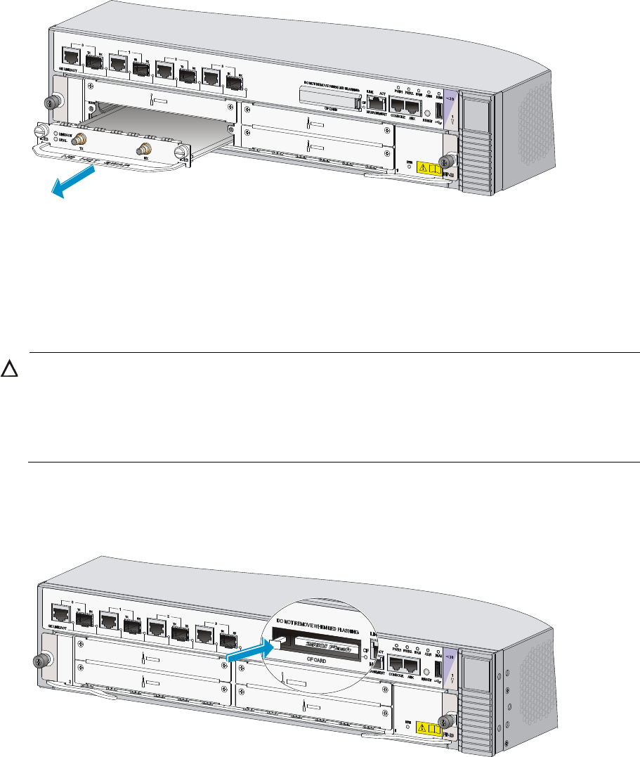
43
2. Holding the handle of the MIM, gently pull the MIM out of slot along the slide rails.
Figure 54 Pulling the MIM out of the slot
3. If you do not install a new MIM in the slot, install a blank panel. To install a new MIM, see
“Installing a HIM/MIM.”
Replacing a CF card
CAUTION:
• To avoid hardware damage, do not remove the CF card when the router is booting or the CF LED is
flashing.
• Before you replace a CF card, open the CF card cover first. For more information, see “Installin
g
a CF
card.”
1. Press the ejector button next to the CF card. The ejector button moves outward so that it projects
from the panel.
Figure 55 Press the ejector button
2. Press the ejector button again. This ejects the CF card partially out of its slot. Pull the CF card out
of its slot.
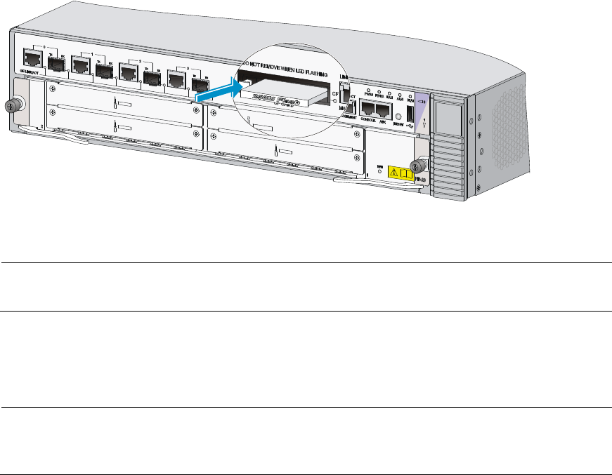
44
Figure 56 Pull the CF card
3. To install a new MIM, see “Installing a CF card.”
NOTE:
To protect the CF card, place it into an antistatic bag.
Replacing a transceiver module
NOTE:
W
hen replacin
g
a transceiver module, make sure that the two transceiver modules connected by the same
optical fiber have the same wavelength.
To replace a transceiver module:
1. Remove the optical fibers from the transceiver module.
2. Pivot the clasp down to the horizontal position.
3. Holding the handle of the transceiver module, gently pull the transceiver module out. See Figure
57.
4. Insert the plastic plug to the removed transceiver module, and put the transceiver module into its
original shipping materials.
5. If you do not install a new transceiver module in the interface, install a dust-proof plug in the
interface. To install a transceiver module, see “Connecting a fiber cable.”
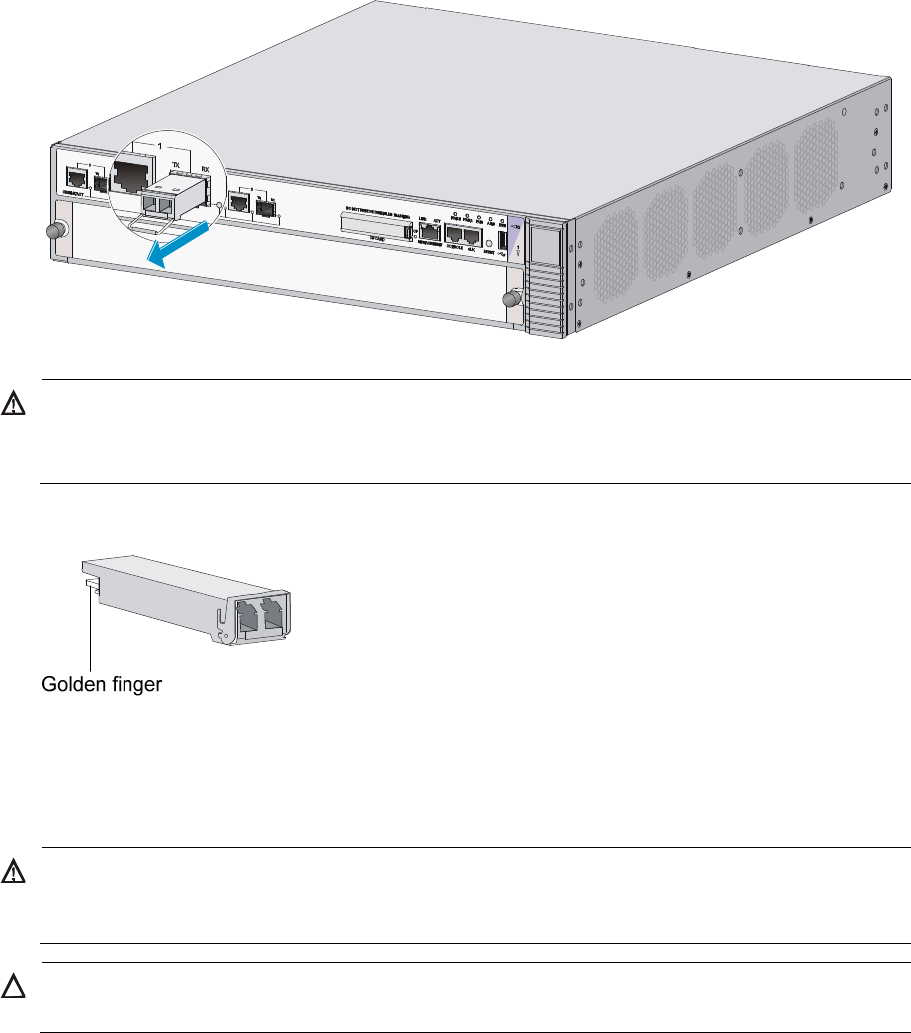
45
Figure 57 Removing a transceiver module
W
ARNING!
• Do not stare into the optical fibers.
• When removing a transceiver module, do not touch the golden finger of the transceiver module.
Figure 58 Transceiver module golden finger
Replacing a fan tray
W
ARNING!
Rotatin
g
fan blades can cause serious injury or cut. Make sure that all fans have stopped rotatin
g
before
you take out the entire fan tray.
CAUTION:
Do not operate the system without a fan tray for more than 2 minutes.
To replace a fan tray:
1. Use a Phillips screwdriver to loosen the captive screw on the fan tray.
2. Grasp the handle of the fan tray with one hand and pull the fan tray part way out the slot. Support
the fan tray bottom with the other hand, and pull the fan tray slowly along the guide rails out of the
slot.
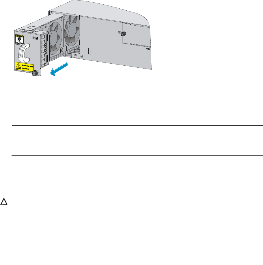
46
Figure 59 Pulling out the fan tray
3. To install a new fan tray, grasp the handle of the fan tray with one hand and support the fan tray
bottom with the other, and slide the fan tray along the guide rails into the slot until the fan tray seats
in the slot and has a firm contact with the backplane.
4. Use a Phillips screwdriver to fasten the captive screw on the fan tray.
NOTE:
• Automatic fan speed adjustment and hot-swapping fan trays are supported.
• Put the removed fan tray in an anti-static bag.
Replacing a memory module
CAUTION:
• Keep the tamper-proof seal on a mountin
g
screw on the chassis cover intact, and if you want to open the
chassis, contact the local agent of HP for permission. Otherwise, HP shall not be liable for any
consequence caused thereby.
• Use the memory modules provided by HP only. Otherwise, the router may be unable to operate
properly.
• For the specifications of memory modules supported, see “Appendix A Chassis views and Technical
specifications.”
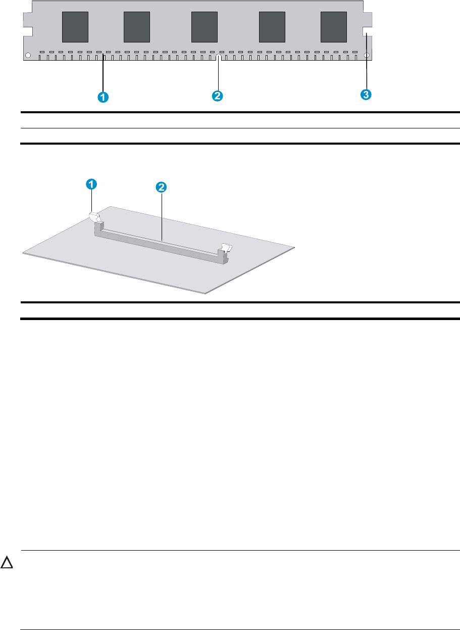
47
Memory module structure
Figure 60 Memory module structure
(1) Connector ed
g
e (2) Polarization notch
(3) Latch notch
Figure 61 Memory module slot
(1) Release latch (2) Memory module slot
When to replace a memory module
Memory modules are removable components of the router.
You need to replace a memory module in the following situations:
• More memory is needed to upgrade the application program.
• The router needs to maintain a large routing table or support other highly memory consuming
operations.
• An existing memory module is damaged.
Replacing a memory module
Opening the chassis cover
CAUTION:
• Screws are available at both sides inside the chassis cover. To avoid damaging the router, do not use
excessive force when you pull the chassis cover backward.
• Unplug all cables from the ports and interface modules and remove all the screws (including the
grounding screw).
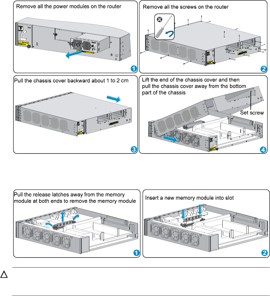
48
Figure 62 Opening the chassis cover
Replacing a memory module
Figure 63 Replacing a memory module
CAUTION:
A
li
g
n the polarization notch of the memory module with the key in the connector when you insert a
memory module.

49
Hardware management and maintenance
NOTE:
The output depends on your router model. For more information about the commands used in this chapter,
see the corresponding command references.
Displaying hardware information of the router
Displaying the software and hardware version information of
the router
Use the display version command to display software and hardware version information of the router.
The output includes the following information: the current software version and hardware version, router
operating time, type and operating time of each interface module.
<Sysname> display version
HP Comware Platform Software
Comware Software, Version 5.20.106, A2701
Copyright (c) 2010-2012 Hewlett-Packard Development Company, L.P.
HP HSR6602 uptime is 0 week, 0 day, 0 hour, 1 minute
Slot 0: HSR6602-XG uptime is 0 week, 0 day, 0 hour, 1 minute
CPU type: FREESCALE P4080 1500MHz
4096M bytes DDR3 SDRAM Memory
8M bytes Flash Memory
128K bytes NVRAM
PCB Version: Ver.A
Basic Logic Version: 1.0
Extend Logic Version: 1.0
Basic BootWare Version: 1.00
Extend BootWare Version: 1.00
[FIXED PORT] CON (Hardware)Ver.A, (Driver)1.0, (Cpld)145.0
[FIXED PORT] AUX (Hardware)Ver.A, (Driver)1.0, (Cpld)145.0
[FIXED PORT] MGE 0/0/0 (Hardware)Ver.A, (Driver)1.0, (Cpld)145.0
[FIXED PORT] GE 0/0/0 (Hardware)Ver.A, (Driver)1.0, (Cpld)145.0
[FIXED PORT] GE 0/0/1 (Hardware)Ver.A, (Driver)1.0, (Cpld)145.0
[FIXED PORT] GE 0/0/2 (Hardware)Ver.A, (Driver)1.0, (Cpld)145.0
[FIXED PORT] GE 0/0/3 (Hardware)Ver.A, (Driver)1.0, (Cpld)145.0
[FIXED PORT] XGE 0/0/0 (Hardware)Ver.A, (Driver)1.0, (Cpld)145.0
[FIXED PORT] XGE 0/0/1 (Hardware)Ver.A, (Driver)1.0, (Cpld)145.0
50
Displaying the operational statistics of the router
When you perform routine maintenance or the system fails, you may need to view the operational
information of each functional module for locating failures. Generally, you need to run display
commands one by one. To collect more information one time, you can execute the display
diagnostic-information command in any view to display or save the operational statistics of multiple
functional modules of the router. This command displays the output of the display clock, display version,
display device, and display current-configuration commands.
• To save the operational statistics of each functional module of the router, type y when the system
prompts you to save or display the diagnostic information.
<Sysname> display diagnostic-information
Save or display diagnostic information (Y=save, N=display)? [Y/N]:y
Please input the file name(*.diag)[flash:/default.diag]:aa.diag
Diagnostic information is outputting to flash:/aa.diag.
Please wait...
Save succeeded.
Execute the more aa.diag command in user view, and then press the Page Up and Page Down
keys to view the contents of the file aa.diag.
• To display the operational statistics of each functional module of the router, type n when the system
prompts you to save or display the diagnostic information. The output is too much and omitted here.
<Sysname> display diagnostic-information
Save or display diagnostic information (Y=save, N=display)? [Y/N]:n
=================================================================
===============running CPU usage information===============
=================================================================
===== Current CPU usage info =====
CPU Usage Stat. Cycle: 23 (Second)
CPU Usage : 3%
CPU Usage Stat. Time : 2011-12-09 10:36:20
CPU Usage Stat. Tick : 0x2(CPU Tick High) 0x7b652c7(CPU Tick Low)
Actual Stat. Cycle : 0x0(CPU Tick High) 0x4774e2b8(CPU Tick Low)
…Omitted…
Displaying the detailed information about a module
Use the display device verbose command to display detailed information of modules in each slot.
<Sysname>display device verbose
Slot No. Board type Status Primary SubSlots
---------------------------------------------------------------------
0 HSR6602-XG Normal Master 0
1 N/A Absent N/A N/A
Use the display device slot slot-number command to display detailed information about the module in the
specified slot.
<Sysname> display device slot 0
Slot 0 : HSR6602-XG
SubSlot No. Card Type Status Max Ports
--------------------------------------------------------

51
0 Fixed SubCard Normal 9
Table 11 Output description
Field Descri
p
tion
Slot 0 Interface module model
SubSlot No. Slot number of the interface module
Card Type Module model. The value NONE indicates that no module is present in the slot.
Status
Running status of the module:
• Absent—No module is present in the slot.
• Fault—The module in the slot is booting, or the module fails and cannot boot properly.
• Normal—The module in the slot is a service module and is operating properly.
Max Ports Maximum number of interfaces that the module supports.
Displaying the electrical label information of a module
Use the display device manuinfo command to display the electrical label information of the module in
each slot.
Electrical label information is also called permanent configuration data or archive information, which
includes the module name, serial number, MAC address, and vendor name.
<Sysname> display device manuinfo
Slot 0:
DEVICE_NAME:HSR6602-XG JG354A
DEVICE_SERIAL_NUMBER:CN12FRX123
MAC_ADDRESS:000F-E123-4567
MANUFACTURING_DATE:2012-02-02
VENDOR_NAME:HP
Slot 1:
DEVICE_NAME:HP HSR6602-XG FIP-20 Flex Intf Pltfm Rtr Mod JG358A
DEVICE_SERIAL_NUMBER:CN12FS1123
MAC_ADDRESS:NONE
MANUFACTURING_DATE:2012-02-02
VENDOR_NAME:HP
Use the display device manuinfo slot slot-number command to display the electrical label
information of the module in the specified slot.
<Sysname> display device manuinfo slot 0
Slot 0:
DEVICE_NAME:HSR6602-XG JG354A
DEVICE_SERIAL_NUMBER:CN12FRX123
MAC_ADDRESS:000F-E123-4567
MANUFACTURING_DATE:2012-02-02
VENDOR_NAME:HP

52
Table 12 Output description
Field Descri
p
tion
Slot 0 Router or interface module slot
DEVICE_NAME Router or module type
DEVICE_SERIAL_NUMBER Router or module serial number
MAC_ADDRESS
MAC address of the router or interface module:
• An device has a MAC address.
• A service module does not have a MAC address, and the field is
displayed as NONE.
MANUFACTURING_DATE Manufacturing data of the router or interface module
VENDOR_NAME Vendor name
The operation is not supported on
the specified board or subslot
Displaying electronic label information by using the display device
manuinfo command is not supported.
Displaying the CPU usage of a module
Use the display cpu-usage command to display the CPU usage of the module in each slot.
<Sysname> display cpu-usage
Slot 0 CPU usage:
1% in last 5 seconds
1% in last 1 minute
1% in last 5 minutes
Table 13 Output description
Field Descri
p
tion
Slot 0 CPU usage CPU usage of the module in slot 0.
1% in last 5 seconds Average CPU usage in the last five seconds (after the router boots, the router
calculates and records the average usage at the interval of five seconds).
1% in last 1 minute Average CPU usage in the last minute (after the router boots, the router
calculates and records the average usage at the interval of one minute).
1% in last 5 minutes Average CPU usage in the last five minutes (after the router boots, the router
calculates and records the average usage at the interval of five minutes).
Displaying the memory usage of a module
Use the display memory command to display the memory information of the device.
<Sysname> display memory
System Total Memory(bytes): 3639590560
Total Used Memory(bytes): 369429132
Used Rate: 10%

53
Table 14 Output description
Field Descri
p
tion
System Total Memory(bytes) Physical memory size (in bytes) of the module
Total Used Memory(bytes) Used memory size (in bytes) of the module
Used Rate Memory usage of the module
Displaying the CF card information
Use the display device cf-card command to display the CF card information.
<Sysname> display device cf-card
Slot No. Dev No. Status Size(M)
-----------------------------------------------
0 0 Normal 495
0 1 Absent N/A
Table 15 Output description
Field Descri
p
tion
Slot No Slot number of the CF card
Dev No.
Device number of the CF card:
• 0 for a built-in CF card
• 1 for an external CF card
Status:
Operational status of the CF card:
• Absent—No CF card is present in the slot.
• Fault—The CF card fails.
• Normal—The CF card is operating properly.
Size (M) Storage capacity of the CF card
Displaying the operational status of the built-in fan
Use the display fan command to display the operational status of the built-in fan.
<Sysname> display fan
Fan 1 State: Normal
Table 16 Output description
Field Descri
p
tion
Fan 1 Number of the fan
State
The fan state:
• Normal—The fan is operating properly.
• Absent—The fan is not in position.
• Fault—The fan fails.

54
Displaying the operational status of power modules
Use the display power command to display the operational status of power modules.
<Sysname> display power
Power 1 State: Absent
Power 2 State: Normal
Table 17 Output description
Field Descri
p
tion
Power Number of the power supply
State
The power supply state:
• Normal—The power supply is operating properly.
• Absent—The power supply is not in position.
• Fault—The power supply fails.
Displaying the alarming thresholds of a module
When the router is operating, too high a temperature and too low a temperature of a module affect the
normal operation of the router. When the temperature of a module exceeds 53°C (127.4°F) or drops
below –10°C (14°F), the system sends traps to prompt you to solve the problem.
To display the alarming thresholds of a module:
Ste
p
Command
Remarks
1. Enter system view system-view N/A
2. (Optional) Display the temperature information
of your router display environment Available in any view
Configuring a combo interface
Combo interface overview
A combo interface is a logical interface comprising an SFP port of a transceiver module and an RJ-45
Ethernet port. The two ports share one forwarding interface, so they cannot work simultaneously. When
you enable either port, the other port is automatically disabled. You can select to activate a port as
needed.
Configuration prerequisites
Use the display interface interface-type interface-number command to find out which port is an SFP port
and which port is an RJ-45 Ethernet port.
• If the output includes “Media type is not sure, Port hardware type is No connector”, it means that the
port is an SFP port. For example, the following output shows that GigabitEthernet 0/0/2 is an SFP
port.
[Sysname] display interface GigabitEthernet 0/0/2

55
GigabitEthernet0/0/2 current state: DOWN
Line protocol current state: DOWN
Description: GigabitEthernet0/0/2 Interface
The Maximum Transmit Unit is 1500
Internet Address is 51.1.1.1/24 Primary
IP Packet Frame Type: PKTFMT_ETHNT_2, Hardware Address: 000f-e200-0005
IPv6 Packet Frame Type: PKTFMT_ETHNT_2, Hardware Address: 000f-e200-0005
Media type is optical fiber, loopback not set, promiscuous mode not set
1000Mb/s, Full-duplex, link type is autonegotiation
Output flow-control is disabled, input flow-control is disabled
Output queue : (Urgent queuing : Size/Length/Discards) 0/100/0
Output queue : (Protocol queuing : Size/Length/Discards) 0/500/0
Output queue : (FIFO queuing : Size/Length/Discards) 0/1024/0
Last clearing of counters: Never
Last 5 seconds input rate 0.00 bytes/sec, 0 bits/sec, 0.00 packets/sec
Last 5 seconds output rate 0.00 bytes/sec, 0 bits/sec, 0.00 packets/sec
Input: 0 packets, 0 bytes, 0 no buffers
0 broadcasts, 0 multicasts, 0 pauses
0 errors, 0 runts, 0 giants
0 crc, 0 align errors, 0 overruns
0 dribbles, 0 drops
Output:0 packets, 0 bytes
0 broadcasts, 0 multicasts, 0 pauses
0 errors, 0 underruns, 0 collisions
0 deferred, 0 lost carriers
• If the output includes “Media type is twisted pair, loopback not set, promiscuous mode not set”, it
means that the interface is an RJ-45 Ethernet port. For example, the following output shows that
GigabitEthernet 0/0/1 is an RJ-45 Ethernet port.
[Sysname] display interface GigabitEthernet 0/0/1
GigabitEthernet0/0/1 current state: DOWN
Line protocol current state: DOWN
Description: GigabitEthernet0/0/1 Interface
The Maximum Transmit Unit is 1500
Internet Address is 66.1.1.1/24 Primary
IP Packet Frame Type: PKTFMT_ETHNT_2, Hardware Address: 000f-e200-0004
IPv6 Packet Frame Type: PKTFMT_ETHNT_2, Hardware Address: 000f-e200-0004
Media type is twisted pair, loopback not set, promiscuous mode not set
1000Mb/s, Full-duplex, link type is autonegotiation
Output flow-control is disabled, input flow-control is disabled
Output queue : (Urgent queuing : Size/Length/Discards) 0/100/0
Output queue : (Protocol queuing : Size/Length/Discards) 0/500/0
Output queue : (FIFO queuing : Size/Length/Discards) 0/1024/0
Last clearing of counters: Never
Last 5 seconds input rate 0.00 bytes/sec, 0 bits/sec, 0.00 packets/sec
Last 5 seconds output rate 0.00 bytes/sec, 0 bits/sec, 0.00 packets/sec
Input: 0 packets, 0 bytes, 0 no buffers
0 broadcasts, 0 multicasts, 0 pauses
0 errors, 0 runts, 0 giants

56
0 crc, 0 align errors, 0 overruns
0 dribbles, 0 drops
Output:0 packets, 0 bytes
0 broadcasts, 0 multicasts, 0 pauses
0 errors, 0 underruns, 0 collisions
0 deferred, 0 lost carriers
Configuring a combo interface
To configure a combo interface:
Ste
p
Command
Remarks
1. Enter system view system-view N/A
2. Enter view of the SFP port or RJ-45
port of the combo interface
interface interface-type
interface-number N/A
3. Activate the RJ-45 Ethernet port or
SFP port
combo enable { copper |
fiber }
Required
By default, the Ethernet port is active.
Displaying transceiver module information and
alarming information
Introduction to transceiver modules
Table 18 Commonly used transceiver modules
Transceiver module
type Application scenarios Whether can be an
optical transceiver
Whether can be
an electrical
transceiver
SFP (Small Form-factor
Pluggable)
Generally used for 100/1000
Mbps Ethernet ports or POS
155M/622M/2.5G ports
Yes Yes
XFP (10 Gigabit Small
Form Factor Pluggable)
Generally used for 10 Gbps
Ethernet ports Yes No
SFP+ Generally used for 10 Gbps
Ethernet ports Yes No
Displaying transceiver module information
To identify transceiver modules, you can use the following command to view the key parameters of the
transceiver modules, including transceiver module type, connector type, central wavelength of the laser
sent, transmission distance, and vendor name or name of the vendor who customizes the transceiver
modules.

57
To display transceiver module information:
Pur
p
ose Command
Remarks
Display key parameters of the transceiver
module in a specified interface
display transceiver interface
[ interface-type interface-number ]
Available for all
transceiver modules
Displaying the alarming information or fault detection
parameters for a transceiver module
The system outputs alarm information for you to locate and troubleshoot faults of transceiver modules. For
the HP-customized transceiver modules, the system can also monitor the key parameters, such as
temperature, voltage, laser bias current, TX power, and RX power. When these parameters are abnormal,
you can take corresponding measures to prevent transceiver module faults.
To display the alarming information or fault detection parameters of a transceiver module:
Pur
p
ose Command
Remarks
Display the current alarm
information of the transceiver
module in a specified interface
display transceiver alarm interface
[ interface-type interface-number ]
Available for all transceiver
modules
NOTE:
For more information about the transceiver module displaying commands, see
HP A6600 Routers
Command References
.
Solving system faults
Solving system faults
When the system detects faults (such as system instruction faults, invalid addresses, data overflow, null
pointers, and division by zero operations) during the operation of the active device or standby device,
you can solve the problem in one of the following methods:
• Reboot—Rebooting the failed device so that the device restores to normal operational status.
• Maintain—Maintaining the current status of the failed device so that the system does not take any
restoration measures. Some software faults are hard to reproduce, and the printed information will
be lost after the router reboots. In this case, you can maintain the current status of the router,
facilitating fault location.
To solve system faults:
Ste
p
Command
Remarks
1. Enter system view system-view N/A
2. (Optional)Specify the system fault solving method
for the active device and standby device
system-failure { maintain |
reboot }
The default method is
reboot.

58
Viewing the system fault solving method
Use the display system-failure command to display the system fault solving method.
<Sysname> display system-failure
System failure handling method: reboot
Saving the current configuration of the router
You can save the current configuration of the router in one of the following methods:
• Fast saving—Executing the save command without the safely keyword. This mode saves the file
more quickly but is likely to lose the existing configuration file if the router reboots or the power fails
during the process. The fast saving mode is suitable for environments where the power supply is
stable.
• Safe saving—Executing the save command with the safely keyword. The mode saves the file more
slowly but can retain the configuration file in the router even if the router reboots or the power fails
during the process. The safe saving mode is preferred in environments where a stable power supply
is unavailable or remote maintenance is involved.
Table 19 To save the current configuration of the router:
Pur
p
ose Command Remarks
Save the current configuration to the specified file, but the
configuration file will not be set as the file for the next startup save file-url Use either
command
Available in any
view
Save the current configuration to the root directory of the storage
medium of the active or standby device and specify the file as the
startup configuration file that will be used at the next system startup
save [ safely ]
NOTE:
• The configuration file must be with extension .cfg.
• Durin
g
the execution of the save command, the startup confi
g
uration file to be used at the next system
startup may be lost if the router reboots or the power supply fails. In this case, the router will boot with
the factory defaults, and after the router reboots, you need to re-specify a startup confi
g
uration file for
the next system startup.
Rebooting the router
When upgrading and maintaining the startup configuration file or configuration file for the router, you
need to reboot the router. To reboot a router, use one of the following methods:
• Use the reboot command to reboot a router.
• Enable the scheduled reboot function at the CLI. You can set a time at which the router can
automatically reboot, or set a delay so that the router can automatically reboot within the delay.
• Power on the router after powering it off, which is also called hard reboot or cold start. Powering off
a running router causes data loss and hardware damages, and therefore is not recommended.
• Use the RESET button.

59
To reboot the router immediately:
Pur
p
ose Command
Remarks
Reboot the router immediately reboot Required
Available in user view
To enable the scheduled reboot function:
Pur
p
ose Command
Remarks
Enable the scheduled reboot
function and specify a specific
reboot time and date
schedule reboot at hh:mm [ date ]
Use either command
The scheduled reboot function is
disabled by default.
Available in user view
Enable the scheduled reboot
function and specify a reboot
waiting time
schedule reboot delay { hh:mm |
mm }
CAUTION:
• If the main system software image file does not exist, do not use the reboot command to reboot the
router. Specify the main system software image file first, and then reboot the router.
• The precision of the rebooting timer is 1 minute. One minute before the rebooting time, the router
prompts “REBOOT IN ONE MINUTE” and reboots in one minute.
• If you are performin
g
file operations when the router is to be rebooted, the system does not execute the
reboot command for security.
• The router does not save the current confi
g
uration when you press the RESET button to reboot the router.
• To avoid system dama
g
e, do not press the RESET button repeatedly when the RUN LED is fast flashin
g
.

60
Troubleshooting
NOTE:
The barcode stuck on the router chassis contains production and servicin
g
information. Before you return
a faulty router for serving, provide the barcode information of the router to your local sales agent.
Router failures
Power status LEDs are off
When the PWR1 and PWR2 LEDs are off, the power module of the router is faulty. For more information
about the PWR1 and PWR2 LEDs, see “Appendix B LEDs.”
To troubleshoot the problem:
1. Check whether a power module is plugged in a right slot.
2. Check whether the power module is powered on normally. A green PWR LED indicates that the
router is powered on properly.
3. If the cause cannot be located in the steps above and the problem persists, contact your local sales
agent.
RUN LED is off
When the RUN LED of the router is off, it indicates that the router is faulty. For more information about the
RUN LED, see “Appendix B LEDs.”
To troubleshoot the problem, contact your local sales agent.
RUN LED fast flashes
Five minutes after the router is powered on, if the RUN LED still fast flashes at 8 Hz, it indicates that the
system software image fails to start or the router is faulty.
To troubleshoot the problem:
1. Check whether the terminal display is correct.
2. Check whether the system software image file properties are correct in the BootWare menu.
3. If the cause cannot be located in the steps above and the problem persists, contact your local sales
agent.
ALM LED is steady on or flashes
If the ALM LED is steady on or flashes, it indicates that the router is faulty. The ALM LED may be on in the
following cases.

61
• When the system is over-temperature. In this case, the system displays the following output:
%Dec 7 11:17:01:436 2011 HP DRVMSG/3/TEMP_ALARM:
CPU temperature is greater than alarm upper limit in slot 0, index is 0.
To solve the problem, check the output (such as the system temperature, insufficient available power, and
PCB voltage alarms) on the serial terminal and the software management tool.
If the cause cannot be located in the steps above and the problem persists, record the above information,
and contact your local sales agent.
Table 20 Router status LED description
LED Status Remarks
PWR1 (red/green)
Off The power module is not in position.
Steady green The power module is supplying power properly.
Steady red No power is input or the power module is faulty
when PWR2 is operating properly.
PWR2 (red/green)
Off The power module is not in position.
Steady green The power module is supplying power properly.
Steady red No power is input or the power module is faulty
when PWR1 is operating properly.
FAN (red/green)
Off No power is input or the fan tray is not is position.
Steady green The fan tray is operating properly.
Steady red The fan tray is faulty.
ALM (red)
Steady on No alarm exists.
Off The router is faulty. You need to view the system
logs immediately.
RUN (green)
Off No power is input or the router is faulty.
Flashes at 1 Hz The router is operating properly.
Flashes at 8 Hz The router is loading software or has not started.
FIP module failure
If the RUN LED of the FIP module is off, it indicates that the FIP module is powered off or faulty.
To troubleshoot the FIP module failure:
1. Check whether the router is powered on.
2. If the router is powered on, check whether the FIP module is plugged in a right slot.
3. If the FIP module is plugged in a right slot, it indicates that the FIP module is faulty. Contact your
local sales agent.
Power module failures
If the router cannot be powered on and the power LED on the front panel is off, it indicates that the power
module is faulty.

62
To troubleshoot the power module failure:
1. Check whether the power switch is turned on.
2. Check whether the power cables of the router are firmly connected.
3. Check whether the switch of the power source is turned on.
4. Check whether the power cord is damaged.
5. If the cause cannot be located in the steps above and the problem persists, contact your local sales
agent.
Table 21 AC power module LED description
LED Status Descri
p
tion
AC OK Off No power is input, or the power supply is faulty.
Steady green The power supply is working properly.
DC OK Off No power is input.
Steady green The power supply is working properly.
Table 22 DC power module LED description
LED Status Descri
p
tion
Input Off No power is input, or the power supply is faulty.
Steady green The power supply is working properly.
Output Off No power is input.
Steady green The power supply is working properly.
Fan failures
Fan tray is absent
After the router is booted, the following information may appear on the configuration terminal:
#Dec 9 09:57:12:560 2011 HP DEVM/1/FAN STATE CHANGES TO FAILURE:
Trap 1.3.6.1.4.1.25506.8.35.12.1.6: fan ID is 1
%Dec 9 09:57:12:560 2011 HP DEVM/3/FAN_ABSENT: Fan 1 is absent.
The output indicates that the fan tray is not in position.
To troubleshoot the fan tray failure:
1. Check whether the fan tray is in position.
2. Check whether the fan tray is in firm contact with the backplane of the router chassis.
3. If the cause cannot be located in the steps above and the problem persists, contact your local sales
agent.
63
ALM LED is red
When the router is running, the ALM LED on the fan tray panel may turn red, and the following
information may appear on the configuration terminal:
%Dec 6 17:13:56:447 2011 HP DEVM/5/FAN_RECOVERED: Fan 1 recovered.
%Dec 6 17:13:58:158 2011 HP DRVMSG/3/FanErr: Fan 1 Error.
#Dec 6 17:13:58:847 2011 HP DEVM/1/FAN STATE CHANGES TO FAILURE:
Trap 1.3.6.1.4.1.25506.8.35.12.1.6: fan ID is 1
%Dec 6 17:13:58:847 2011 HP DEVM/2/FAN_FAILED: Fan 1 failed.
The output shows that fan 1 is faulty.
To solve the problem, check whether any foreign object has entered the fan tray.
If the cause cannot be located in the steps above and the problem persists, contact your local sales
agent.
HIM/MIM failures
When a HIM/MIM is plugged while the router is running, the following information may appear on the
configuration terminal:
%Dec 30 09:54:10:264 2011 66mcp DRVICOUT/1/DrvIcOutStr:
Card in Slot 4 Sublot 2 can not be recognized !
The output indicates that the HIM/MIM is faulty or the router cannot recognize the HIM/MIM.
To troubleshoot the HIM/MIM failure:
1. Check whether the HIM/MIM is firmly seated.
2. Check whether the HIM is correctly plugged into an FIP-20 module. An FIP-10 module does not
support HIMs.
3. Check whether the interface module connector pins of the FIP module are bent.
4. If the cause cannot be located in the steps above and the problem persists, contact your local sales
agent.
Configuration system problems
If the configuration environment setup is correct, the configuration terminal displays boot information
when the router is powered on. If the setup is incorrect, the configuration terminal displays nothing or
garbled text.
No terminal display
If the configuration terminal displays nothing when the router is powered on, To troubleshoot the failure:
1. Check the following items.
{ The power supply system works properly.
{ The console cable is properly connected.

64
2. If no problem is found, check the following reasons that may apply:
{ The console cable is connected to an incorrect serial port (the serial port in use is not the one set
on the terminal).
{ The properties of the terminal are incorrect. You must configure the console terminal as follows:
set Bits per second to 9600, Data bits to 8, Parity to None, Stop bits to 1, Flow control to None,
and Terminal Emulation to VT100.
{ The console cable fails.
3. If the cause cannot be located in the steps above and the problem persists, contact your local sales
agent.
Garbled terminal display
If terminal display is garbled, To solve this problem:
1. Make sure that the Data bits field is set to 8 for the console terminal. If the Data bits field is set to
5 or 6, the console terminal will display garbled characters.
2. Make sure that the Bits per second field is set to 9600 kbps. An incorrect bits per second may also
cause the configuration terminal to display garbled characters.
No response from the serial port
If the serial port gives no response, check that the serial port settings are correct.
NOTE:
For more information about the serial port settings, see “Setting terminal parameters.”
Dealing with password loss
CAUTION:
Dealing with console login password loss and user privilege level password loss from BootWare menus is
disruptive.
How to deal with console login password loss and user privilege level password loss depends on the
state of password recovery capability (see Figure 64). Password recovery capability controls console
user access to the device configuration and SDRAM from BootWare menus.
• If password recovery capability is enabled, a console user can access the device configuration
without authentication and configure new passwords.
• If password recovery capability is disabled, a console user must restore the factory-default
configuration before configuring new passwords. Restoring the factory-default configuration deletes
the main and backup next-startup configuration files.
To enhance system security, disable password recovery capability.
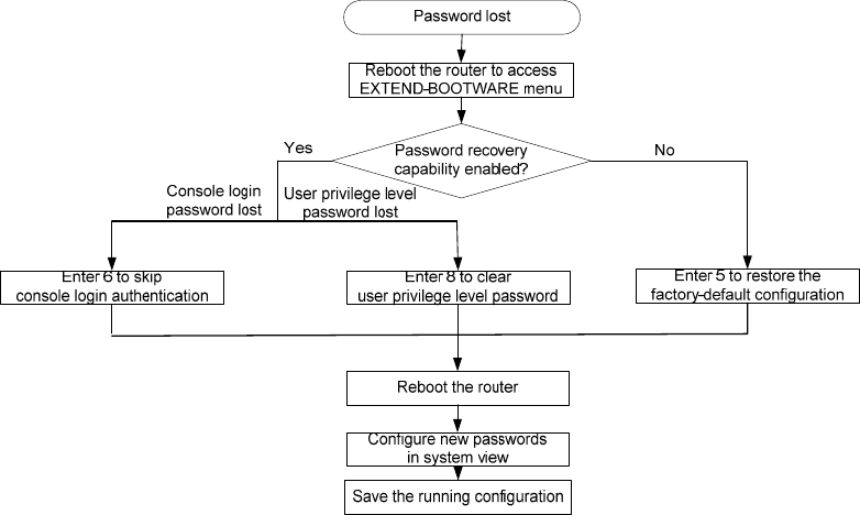
65
Figure 64 Dealing with password loss
Examining the state of password recovery capability
1. Reboot the router.
System is starting...
Press Ctrl+D to access BASIC-BOOTWARE MENU
Press Ctrl+T to start memory test
Booting Normal Extend BootWare........
The Extend BootWare is self-decompressing......................Done!
****************************************************************************
* *
* HP Router BootWare, Version 1.04 *
* *
****************************************************************************
Copyright (c) 2010-2012 Hewlett-Packard Development Company, L.P.
Compiled Date : Dec 26 2012
CPU Type : P2020
CPU L1 Cache : 32KB
CPU Clock Speed : 1000MHz
Memory Type : DDR3 SDRAM
Memory Size : 4096MB
Memory Speed : 667MHz
Flash Size : 8MB
cfa0 Size : 999MB
NVRAM Size : 128KB
BASIC CPLD Version : 1.0
EXTEND CPLD Version : 1.0

66
PCB Version : Ver.B
BootWare Validating...
Backup Extend BootWare is newer than Normal Extend BootWare,Update? [Y/N]
Press Ctrl+B to enter extended boot menu...
2. Press Ctrl + B within three seconds after the "Press Ctrl+B to enter extended boot menu..." prompt
message appears.
BootWare password: Not required. Please press Enter to continue.
3. Press Enter and read the password recovery capability state message displayed before the
EXTEND-BOOTWARE menu.
Password recovery capability is enabled.
Note: The current operating device is cfa0
Enter < Storage Device Operation > to select device.
===========================<EXTEND-BOOTWARE MENU>===========================
|<1> Boot System |
|<2> Enter Serial SubMenu |
|<3> Enter Ethernet SubMenu |
|<4> File Control |
|<5> Restore to Factory Default Configuration |
|<6> Skip Current System Configuration |
|<7> BootWare Operation Menu |
|<8> Clear Super Password |
|<9> Storage Device Operation |
|<0> Reboot |
============================================================================
Ctrl+Z: Access EXTEND-ASSISTANT MENU
Ctrl+F: Format File System
Enter your choice(0-9):
Dealing with console login password loss when password
recovery capability is enabled
1. Reboot the router to access the EXTEND-BOOTWARE menu, and then enter 6.
The current mode is password recovery.
Note: The current operating device is cfa0
Enter < Storage Device Operation > to select device.
===========================<EXTEND-BOOTWARE MENU>===========================
|<1> Boot System |
|<2> Enter Serial SubMenu |
|<3> Enter Ethernet SubMenu |
|<4> File Control |
|<5> Restore to Factory Default Configuration |
|<6> Skip Current System Configuration |
|<7> BootWare Operation Menu |
67
|<8> Clear Super Password |
|<9> Storage Device Operation |
|<0> Reboot |
============================================================================
Ctrl+Z: Access EXTEND-ASSISTANT MENU
Ctrl+F: Format File System
Enter your choice(0-9): 6
After the configuration skipping flag is set successfully, the following message appears:
Flag Set Success.
2. When the EXTEND-BOOTWARE menu appears again, enter 0 to reboot the router.
The router starts up with empty configuration.
3. To use the configuration in the next-startup configuration file, load the file in system view.
<HP> system-view
[HP] configuration replace file startup.cfg
Current configuration will be lost, save current configuration? [Y/N]:n
Info: Now replacing the current configuration. Please wait...
Info: Succeeded in replacing current configuration with the file startup.cfg.
4. Configure a new console login password.
In the following example, the console login authentication mode is password and the authentication
password is 123456. For security, the password is always saved in ciphertext to the configuration file,
regardless of whether you specify the simple keyword or cipher keyword for the set authentication
password command.
<HP> system-view
[HP] user-interface console 0
[HP-ui-console0] authentication-mode password
[HP-ui-console0] set authentication password cipher 123456
5. To make the settings take effect after a reboot, save the running configuration to the next-startup
configuration file.
[HP] save
Dealing with user privilege level password loss when password
recovery capability is enabled
1. Reboot the router to access the EXTEND-BOOTWARE menu, and then enter 8.
The current mode is password recovery.
Note: The current operating device is cfa0
Enter < Storage Device Operation > to select device.
===========================<EXTEND-BOOTWARE MENU>===========================
|<1> Boot System |
|<2> Enter Serial SubMenu |
|<3> Enter Ethernet SubMenu |
|<4> File Control |
|<5> Restore to Factory Default Configuration |
|<6> Skip Current System Configuration |
|<7> BootWare Operation Menu |
68
|<8> Clear Super Password |
|<9> Storage Device Operation |
|<0> Reboot |
============================================================================
Ctrl+Z: Access EXTEND-ASSISTANT MENU
Ctrl+F: Format File System
Enter your choice(0-9): 8
The router deletes the user privilege level password configuration commands from the main next-startup
configuration file. After the operation is completed, the following message appears:
Clear Super Password Success!
2. When the EXTEND-BOOTWARE menu appears again, enter 0 to reboot the router.
The router starts up with the main next-startup configuration file.
3. Configure new passwords for user privilege levels.
In the following example, the password 123456 is configured for user privilege level 3. For security, the
password is always saved in ciphertext to the configuration file, regardless of whether you specify the
simple keyword or cipher keyword for the super password command.
<HP> system-view
[HP] super password cipher 123456
4. To make the setting take effect after a reboot, save the running configuration to the next-startup
configuration file.
[HP] save
Dealing with password loss when password recovery
capability is disabled
1. Reboot the router to access the EXTEND-BOOTWARE menu, and enter 5.
The current mode is no password recovery.
Note: The current operating device is cfa0
Enter < Storage Device Operation > to select device.
===========================<EXTEND-BOOTWARE MENU>===========================
|<1> Boot System |
|<2> Enter Serial SubMenu |
|<3> Enter Ethernet SubMenu |
|<4> File Control |
|<5> Restore to Factory Default Configuration |
|<6> Skip Current System Configuration |
|<7> BootWare Operation Menu |
|<8> Clear Super Password |
|<9> Storage Device Operation |
|<0> Reboot |
============================================================================
Ctrl+Z: Access EXTEND-ASSISTANT MENU
Ctrl+F: Format File System
Enter your choice(0-9): 5
2. At the prompt for confirmation, enter Y.
69
The router deletes its main and backup next-startup configuration files and restores the factory-default
configuration.
The current mode is no password recovery. The configuration files will be
deleted, and the system will start up with factory defaults, Are you sure to
continue?[Y/N]Y
Setting...Done.
3. When the EXTEND-BOOTWARE menu appears again, enter 0 to reboot the router.
The router starts up with the factory-default configuration.
4. Configure a new console login password (see "Configure a new console login password.") or
new user privilege level passwords (see "Configure new passwords for user privilege levels.").
5. To make the settings take effect after a reboot, save the running configuration to the next-startup
configuration file.
[HP] save
Cooling system failure
When the environmental temperature of a module reaches or exceeds the high temperature threshold,
the fans rotate at full speed, and the following information appears on the configuration terminal:
%Dec 7 11:49:16:436 2011 HP DRVMSG/3/TEMP_WARNING:
Environment temperature is greater than warning upper limit in slot 0, index is 1.
#Dec 7 11:49:20:444 2011 HP DEVM/1/BOARD TEMPERATURE UPPER:
Trap 1.3.6.1.4.1.25506.8.35.12.1.16: chassisIndex is 0, slotIndex 0.0
%Dec 7 11:49:20:444 2011 HP DEVM/4/BOARD_TEMP_TOOHIGH: Board temperature is too high on
Chassis 0 Slot 0, type is HSR6602-XG.
After the router runs for a period of time, the environmental temperature of the router will drop below the
high temperature threshold, and the following information appears on the configuration terminal:
%Dec 7 11:50:11:436 2011 HP DRVMSG/3/TEMP_NOWARNING:
Environment temperature recovered from TEMP_WARNING in Slot 0, index is 1.
%Dec 7 11:50:11:436 2011 HP DRVMSG/3/TEMP_SYSNOWARNING:
System temperature recovered from TEMP_WARNING.
#Dec 7 11:50:13:244 2011 HP DEVM/1/BOARD TEMPERATURE NORMAL:
Trap 1.3.6.1.4.1.25506.8.35.12.1.17: chassisIndex is 0, slotIndex 0.0
%Dec 7 11:50:13:244 2011 HP DEVM/5/BOARD_TEMP_NORMAL: Board temperature changes to normal
on Chassis 0 Slot 0, type is HSR6602-XG.
When the environmental or CPU temperature of a module exceeds the critical temperature threshold, the
ALM LED of the router is red.
%Dec 7 11:17:01:436 2011 HP DRVMSG/3/TEMP_ALARM:
CPU temperature is greater than alarm upper limit in slot 0, index is 0.
To view the high temperature threshold and critical temperature threshold of each module, use the
display environment command.
To troubleshoot the cooling system failure:

70
1. Check whether the fans are running properly.
2. Check whether the working environment of the module is well ventilated.
3. Use the display environment command to check whether the temperature in the module keeps
rising.
4. If the temperature inside the module still reaches the critical temperature threshold, power off the
router immediately and contact your local sales agent.
NOTE:
For more information about the display environment command, see
HP A6600 Routers Command
References
.
Interface module, cable, and connection failure
After an HIM/MIM is installed and the router is powered on, the LEDs on the HIM/MIM panel may
indicate abnormal operation.
To solve this problem:
1. Check whether the HIM/MIM cable is correctly selected.
2. Check whether the HIM/MIM cable is correctly connected.
3. Use the display command to check whether the interface of the interface module has been
correctly configured and is working properly.
Software upgrade failures
No response from the serial port
The serial port gives no response.
To solve the problem, check whether the serial port settings are correct (whether the Bits per second field
is set to 9600 kbps).
NOTE:
For more information about the serial port settings, see “Setting terminal parameters.”
TFTP upgrade failure
Start the router, and upgrade the software through TFTP. The following problems may occur:
1. The CF card has no enough space.
File will be transferred in binary mode
Downloading file from remote TFTP server, please wait...\
Failed to write data into storage device, maybe no enough space on device
To solve this problem, delete some files in the CF card or use a new CF card so that enough space
is available for the application program.
2. The file to be downloaded is not found.
File will be transferred in binary mode

71
Downloading file from remote TFTP server, please wait...
File not found.
To solve this problem, type the correct file name.
3. The configuration of the network port is incorrect.
Can't connect to the remote host
To solve this problem, configure the network port correctly, and make sure that the network port is
up and you can successfully ping the TFTP server from the network port.
NOTE:
The barcode stuck on the router chassis contains production and servicin
g
information. Before you return
a faulty router for serving, provide the barcode information of the router to your local sales agent.
FTP upgrade failure
Start the router, and upgrade the software through FTP. The following problems may occur:
1. The CF card has no enough space.
227 Entering Passive Mode (192,168,1,10,10,204)
150 "xxx" file ready to send (xxx bytes) in ASCII mode
FTP: Error Writing Local File(Screen).
To solve this problem, delete some files in the CF card or use a new CF card so that enough space
is available for the application program.
2. The file to be downloaded is not found.
227 Entering Passive Mode (192,168,1,10,10,203)
550 Error: File xxx does not exist
FTP: Error Writing Local File(Screen).
To solve this problem, type the correct file name.
3. The configuration of the network port is incorrect.
FTP: Unrecognized host or wrong IP address!
To solve this problem, configure the network port correctly, and make sure that the network port is
up and you can successfully ping the FTP server from the network port.
Application file missing errors
When none of the main, backup, and secure application files exists, the system displays the following
information at startup:
BootWare Validating...
Application program does not exist.
Please input BootWare password:
If you select 1 on the main BootWare menu, the system displays the following information:
Starting to get the main application file--cfa0:/main.bin!
The main application file does not exist--cfa0:/main.bin!
Starting to get the backup application file--cfa0:/backup.bin!
The backup application file does not exist--cfa0:/backup.bin!
Starting to get the secure application file--cfa0:/secure.bin!
The secure application file does not exist--cfa0:/secure.bin!
72
Booting App fails!
The name of the main, backup, and secure application files vary by user settings.
A possible reason for the errors is that the main, backup, and secure application files have been deleted
or damaged.
To solve this problem, download the application package again or set the file properties in the BootWare
file list.
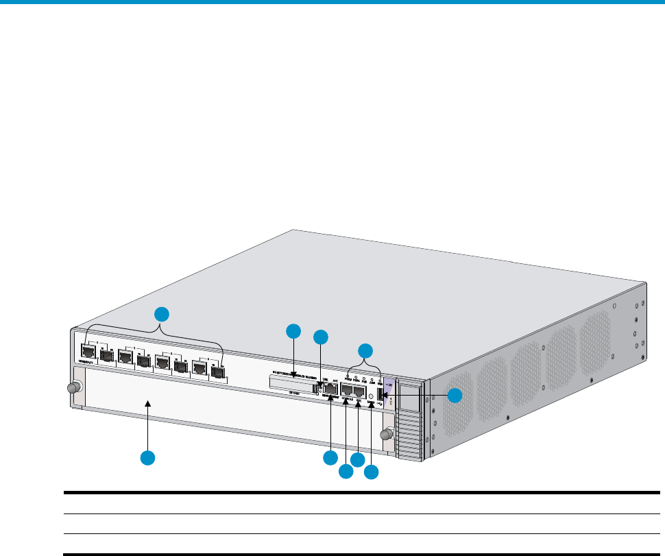
73
Appendix A Chassis views and Technical
specifications
Chassis views
Figure 65 HSR6602-G/HSR6602-G TAA front view
(1) 1000 Mbps Ethernet port (2) CF card slot (CF CARD)
(3) CF card LED (4) Status LED
(5) USB port (6) Reset button (RESET) (7) Auxiliary port (AUX)
(8) Console port (CONSOLE) (9) Mana
g
ement Ethernet port
(MANAGEMENT) (10) FIP slot (slot 1)
4
123
5
76
8
9
10
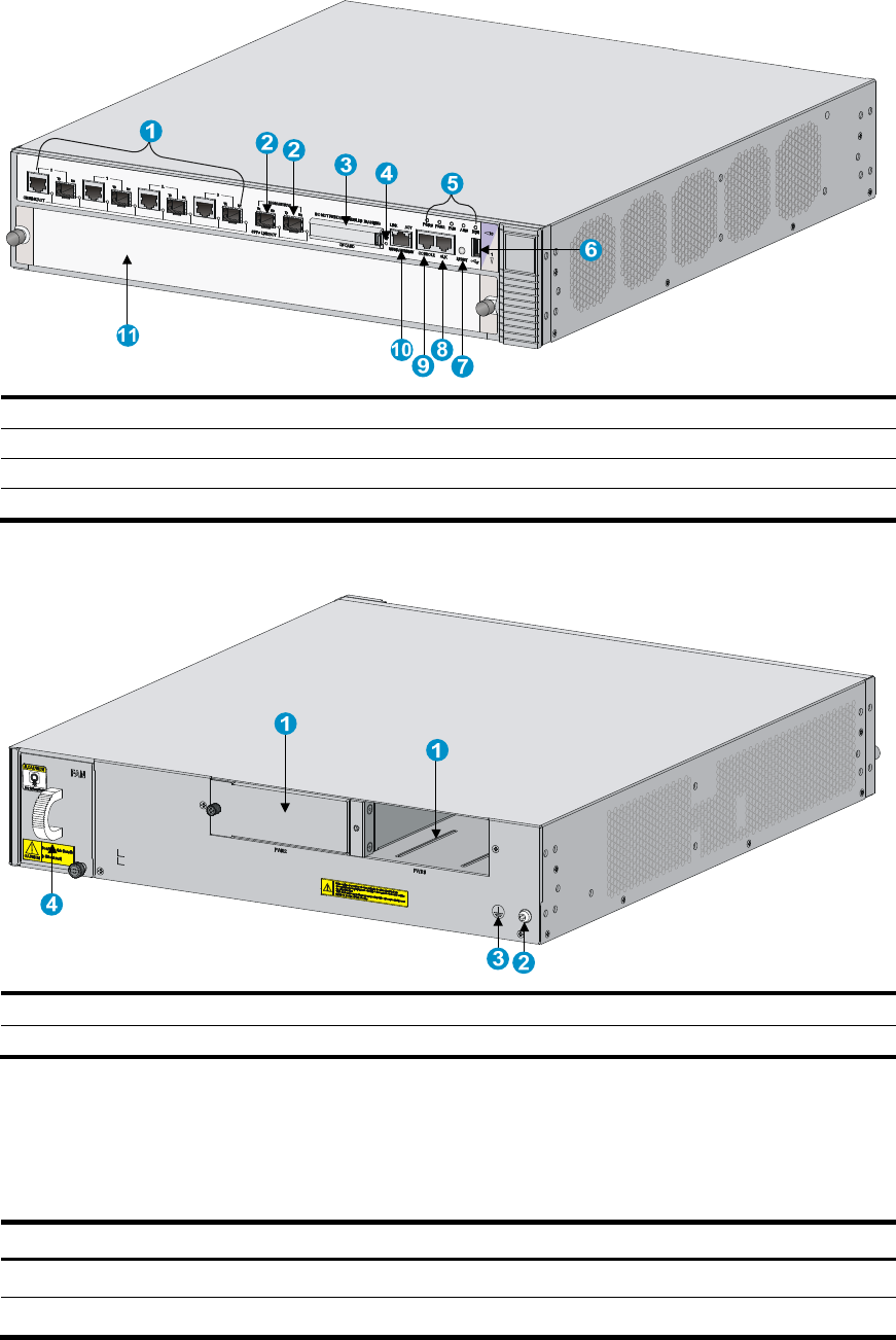
74
Figure 66 HSR6602-XG/HSR6602-XG TAA front view
(1) 1000 Mbps Ethernet port (2) 10 Gbps Ethernet port (3) CF card slot (CF CARD)
(4) CF card LED (5) Status LED
(6) USB port
(7) Reset button (RESET) (8) Auxiliary port (AUX)
(9) Console port (CONSOLE)
(10) Management Ethernet port (MANAGEMENT) (11) FIP slot (slot 1)
Figure 67 HSR6600 rear view
(1) Power module slots (PWR1, PWR2)
(2) Groundin
g
screw
(3) Grounding sign (4) Fan tray
Dimensions and weights
Table 23 Dimensions and weight
Item Dimensions (H ×
W ×
D)
Wei
g
ht
Chassis 88 × 440 × 480 mm (3.46 × 17.32 × 18.90 in) 12.1 kg (26.68 lb)
FIP module 45 × 399 × 412 mm (1.77 × 15.71 × 16.22 in) 3 kg (6.61 lb)

75
Item Dimensions (H ×
W ×
D)
Wei
g
ht
Power module 40 × 114 × 235 mm (1.57 × 4.49 × 9.25 in) 1.15 kg (2.54 lb)
Fan tray 84 × 61 × 459 mm (3.31 × 2.40 × 18.07 in) 0.85 kg (1.87 lb)
Storage media
Table 24 Storage media specifications
Item S
p
ecification
Flash 8 MB
FIP module
DDR3 SDRAM
• HSR6602-G/HSR6602-G TAA—2 GB (default), 4 GB (maximum)
• HSR6602-XG/HSR6602-XG TAA—4 GB (default), 4 GB (maximum)
CF card
• Built-in—512 MB (default)
• External—1 GB (maximum)
Power consumption
Table 25 Power consumption
Item S
p
ecification
System power consumption
• HSR6602-G/HSR6602-G TAA—160 W
• HSR6602-XG/HSR6602-XG TAA—160 W
Card power consumption
• FIP-10—33 W
• FIP-20—65 W
Fan tray power consumption 30 W
Interface module power consumption
See HP 6600/HSR6600/HSR6800 Router Series Interface Module
Guide.
Power module
Each HP HSR6600 router provides two power module slots, PWR1 and PWR2 on its rear panel, and is
shipped with a filler panel on PWR2. You can install one or two power modules for the router as needed.
NOTE:
• No power modules are supplied with the router. Purchase them yourself.
• The router does not support intermixing of AC and DC power modules.
AC power module
The supported AC power module is PSR300-12A, which provides a maximum output power of 300 W.
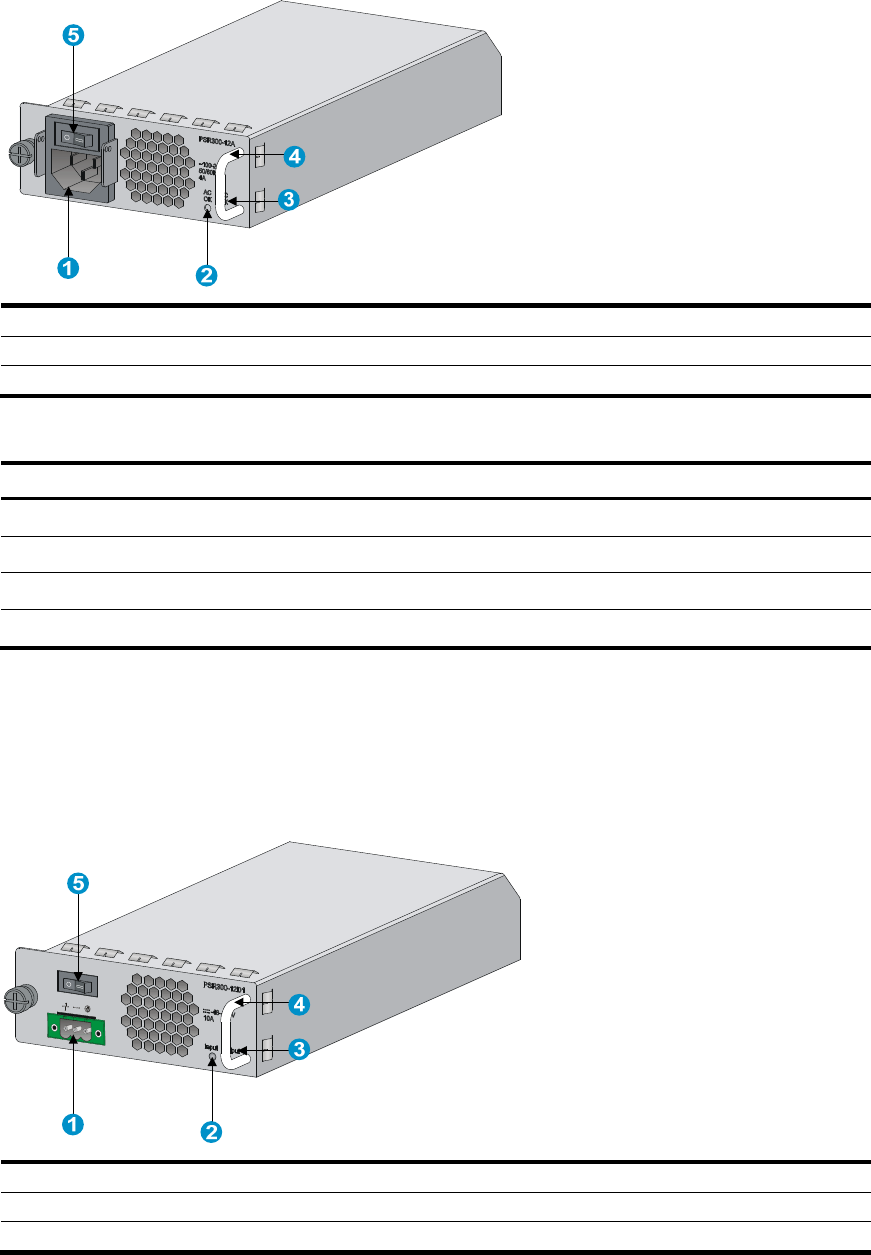
76
Figure 68 AC power module appearance
(1) AC-input power receptacle (2) Power input
status LED
(3) Power output status LED (4) Handle
(5) Power switch
Table 26 AC power module specifications
Item S
p
ecification
Model PSR300-12A
Rated voltage range 100 VAC to 240 VAC; 50 Hz or 60 Hz
Maximum input current 4 A
Maximum power 300 W
DC power module
The supported DC power module is PSR300-12D1, which provides a maximum output power of 300 W.
Figure 69 DC power module appearance
(1) DC-input terminal block (2) Power input status LED
(3) Power output status LED (4) Handle
(5) Power switch
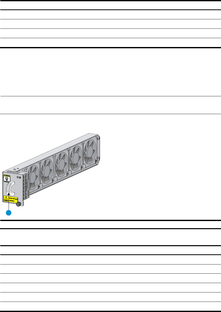
77
Table 27 DC power module specifications
Item S
p
ecification
Model PSR300-12D1
Rated voltage range –60 VDC to –48 VDC
Maximum input current 10 A
Maximum power 300 W
Fan tray
Each HP HSR6600 router provides a fan tray slot on its rear panel. You can install a fan tray for heat
dissipation.
NOTE:
The fan tray is supplied with the router.
Figure 70 Fan tray
(1) Handle
Table 28 Fan tray specifications
Item S
p
ecification
Model RT-FANF
Automatic speed adjustment Supported
Fool-proof design Supported
Hot swapping Supported
Noise level 55dBA to 65dBA
Heat dissipation 102 BTU
1

78
Port specifications
Ports and slots
Table 29 Port and slot specifications
Item Descri
p
tion
Console port 1
AUX port 1
USB port 1
Ethernet port
• HSR6602-G/HSR6602-G TAA—Four GE combo interfaces
• HSR6602-XG/HSR6602-XG TAA—Four combo interfaces and two 10 GE ports
CF card slot 1
Interface module slot 1, supports FIP-10/20
Console port
Table 30 Console port specifications
Item S
p
ecification
Connector RJ-45
Standard compliant Asynchronous EIA/TIA-232
Baud rate 9600 bps (default) to 115200 bps
Transmission distance 15 m (49.21 ft)
Services Provides connection to the serial port of a local PC to run the terminal
emulation program
AUX port
Table 31 AUX port specifications
Item S
p
ecification
Connector RJ-45
Standard compliant Asynchronous EIA/TIA-232
Baud rate 9600 bps (default) to 115200 bps
Services Connects the serial port of a remote PC through a pair of modems to
establish a dial-up connection with the PC

79
Management Ethernet port
The management Ethernet port is a 10Base-T/100Base-TX/1000Base-T RJ-45 port. It allows you to
upgrade software and manage the router through a network management server without using any
service interface of the router. The management Ethernet port is used only for managing the router and
it has no service processing capabilities such as data forwarding.
Table 32 Management Ethernet port specifications
Item S
p
ecification
Connector RJ-45
Interface type Automatic MDI/MDI-X
Frame format Ethernet_II
Ethernet_SNAP
Interface speed and duplex mode
10 Mbps, half/full-duplex
100 Mbps, half/full-duplex
1000 Mbps, full-duplex
Combo interface
Copper Ethernet port
Table 33 Copper Ethernet port specifications
Item S
p
ecification
Connector RJ-45
Interface type Automatic MDI/MDI-X
Frame format Ethernet_II
Ethernet_SNAP
Interface speed and duplex mode
10 Mbps, half/full-duplex
100 Mbps, half/full-duplex
1000 Mbps, full-duplex
NOTE:
• The media dependent interface (MDI) standard is typically used on the Ethernet port of network
adapters. The media dependent interface crossover (MDI-X) standard is typically used on hubs or LAN
switches.
• For a combo interface, you can use either the copper port or the fiber port. To switch between the copper
and fiber ports, use the combo enable { copper | fiber } command in interface view.

80
Fiber Ethernet port
Table 34 Fiber Ethernet port specifications
Item S
p
ecification
Connector type LC
Transceiver module type SFP
Interface standards 802.3, 802.3u, and 802.3ab
Transmission
power
Type
Short-haul
multi-mode
(850 nm)
Mid-haul
single mode
(1310 nm)
Long haul
(1310 nm)
Long haul
(1550 nm)
Super long
haul (1550
nm)
Minimum –9.5 dBm –9 dBm –2 dBm –4 dBm –4 dBm
Maximum 0 dBm –3 dBm 5 dBm 1 dBm 2 dBm
Receive sensitivity –17 dBm –20 dBm –23 dBm –21 dBm –22 dBm
Central wavelength 850 nm 1310 nm 1310 nm 1550 nm 1550 nm
Fiber type
62.5/125
m
multi-mode
9/125 m
single mode
9/125 m
single mode
9/125 m
single mode
9/125 m
single mode
Max. transmission distance 0.55 km
(0.34 miles)
10 km (6.21
miles)
40 km
(24.86 miles)
40 km
(24.86 miles)
70 km
(43.50 miles)
Operating mode 100/1000 Mbps, full duplex
10 Gbps Ethernet port
The HSR6602-XG/HSR6602-XG TAA provides two 10 Gbps Ethernet ports. 10 Gbps SFP+ ports do not
support 1000 Mbps transceiver modules.
Table 35 10 Gbps Ethernet port specifications
Item S
p
ecification
Protocol 802.3ae
Connector type LC
Transceiver module type SFP+
Physical layer 10GBASE-R/W
Transmission rate
• LAN PHY—10.3125 Gbps
• WAN PHY—9.95328 Gbps
Table 36 10 Gbps SFP+ transceiver module specifications
Model Central
wavelen
g
th
Connector
t
yp
e
Fiber type Max. transmission
distance
SFP-XG-SX-MM850-A 850 nm LC 50/125m multi-mode 300 m (984.25 ft)
SFP-XG-LX-SM1310 1310 nm LC 9/125m single mode 10 km (6.21 miles)
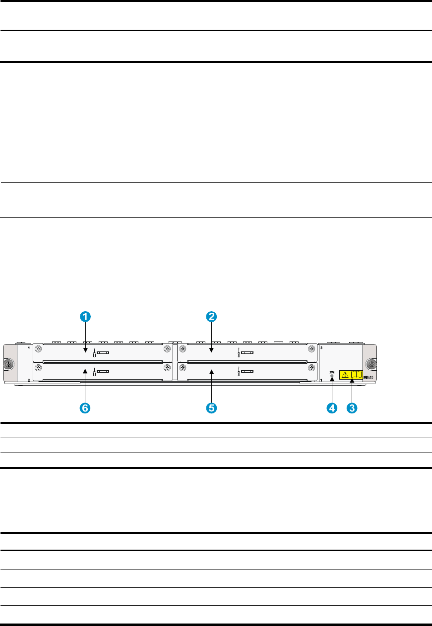
81
Model Central
wavelen
g
th
Connector
t
yp
e
Fiber type Max. transmission
distance
SFP-XG-LH40-SM155
0 1550 nm LC 9/125m single mode 40 km (24.86 miles)
Flexible interface platform modules
The HSR6600 Router Series supports flexible interface platform (FIP) modules FIP-10 and FIP-20. You can
install High-speed Interface Modules (HIMs) and Multifunctional Interface Modules (MIMs) on a FIP to
support different network services as needed. A FIP module is located on the lower part of the front
panel.
NOTE:
No FIP modules are supplied with the router. Purchase them yourself.
FIP-10
The FIP-10 supports only MIMs, and you can plug at most four MIMs into a FIP.
Figure 71 FIP-10 front panel
(1) Slot 4 (2) Slot 3
(3) OPEN BOOK mark (4) Status LED (RUN)
(5) Slot 1 (6) Slot 2
The OPEN BOOK mark indicates that the operator must read the following sections before working with
the FIP:
Table 37 References for FIP operations
O
p
eration Reference
Install and remove the FIP See “Installing a FIP module” and “Replacing a FIP module.”
Install and remove MIMs See “Installing a HIM/MIM” and “Replacing a HIM/MIM.”
Connect network cables See “Connecting an Ethernet cable.”
Connect optical fibers See “Connecting a fiber cable.”
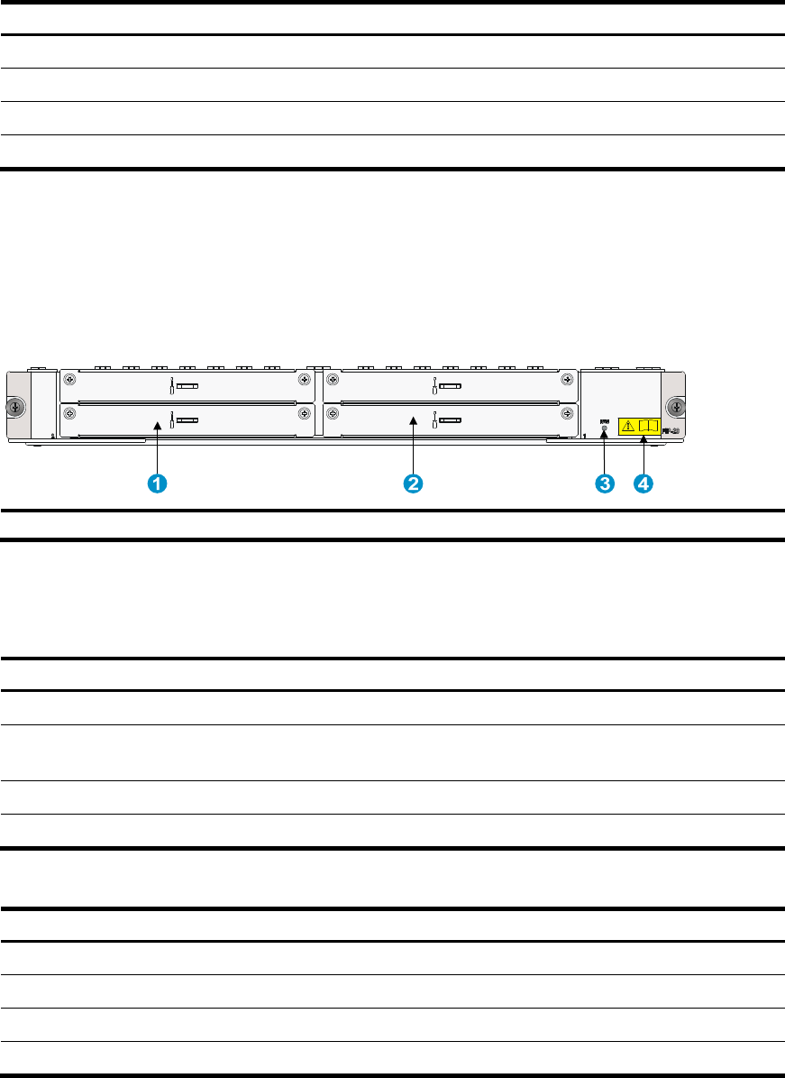
82
Table 38 FIP-10 specifications
Item S
p
ecification
HIM Not supported
MIM 4 MIMs supported at the same time
Hot-swapping Supported
Slot Four
FIP-20
You can plug up to two HIMs or two MIMs into the FIP-20. The FIP-20 also supports intermix of a HIM and
a MIM.
Figure 72 FIP-20 front panel
(1) Slot 2 (2) Slot 1
(3) Status LED
(4) OPEN BOOK mark
The OPEN BOOK mark indicates that the operator must read the following sections before working with
the FIP:
Table 39 References for FIP operations
O
p
eration Reference
Install and remove the FIP See “Installing a FIP module” and “Replacing a FIP module.”
Install and remove interface
modules
See “错误!未找到引用源。”, “Installing a HIM/MIM”, 错误!未找到引用
源。, and “Replacing a HIM/MIM.”
Connect network cables See “Connecting an Ethernet cable.”
Connect optical fibers See “Connecting a fiber cable.”
Table 40 FIP-20 specifications
Item S
p
ecification
HIM 2 HIMs supported
MIM 2 MIMs supported
Hot swapping Supported
Interface module slot 2

83
Interface modules
You can install HIMs to provide 10-Gbps service processing capability and install MIMs to provide
high-density narrowband aggregation. The HIMs and MIMs can offer a variety of interfaces, including
serial, Ethernet, POS, and E1.
NOTE:
• No interface modules are supplied with the router. Purchase them yourself.
• An interface module must be installed on a FIP.
• For information about interface module specifications, see
HP 6600/HSR6600/HSR6800 Router Serie
s
Interface Module Guide
.
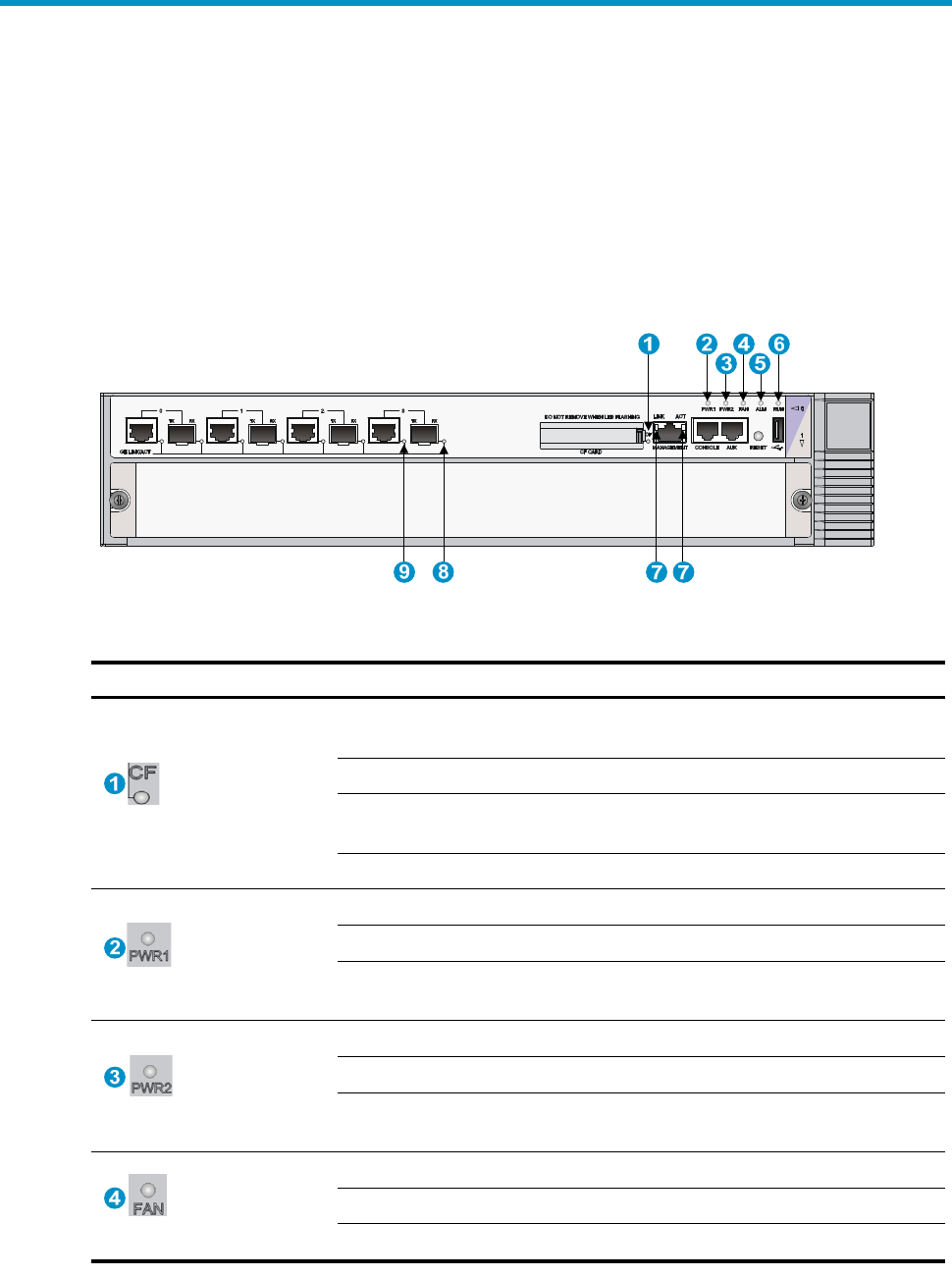
84
Appendix B LEDs
Panel LEDs
HSR6602-G/HSR6602-G TAA panel LEDs
Figure 73 HSR6602-G/HSR6602-G TAA front view
Table 41 HSR6602-G/HSR6602-G TAA panel LED description
LED Status
Descri
p
tion
(yellow/green)
CF
Off No CF card is in position or the CF card cannot be
recognized.
Steady green A CF card is in position and has been detected.
Flashing green The system is accessing the CF card. In this state, do
not remove the CF card.
Steady yellow It is a non HP CF card.
(red/green)
PWR1
Off The power module is not in position.
Steady green The power module is supplying power properly.
Steady red No power is input or the power module is faulty when
PWR2 is operating properly.
(red/green)
PWR2
Off The power module is not in position.
Steady green The power module is supplying power properly.
Steady red No power is input or the power module is faulty when
PWR1 is operating properly.
(red/green)
FAN
Off No power is input or the fan tray is not in position.
Steady green The fan tray is working properly.
Steady red The fan tray is faulty.
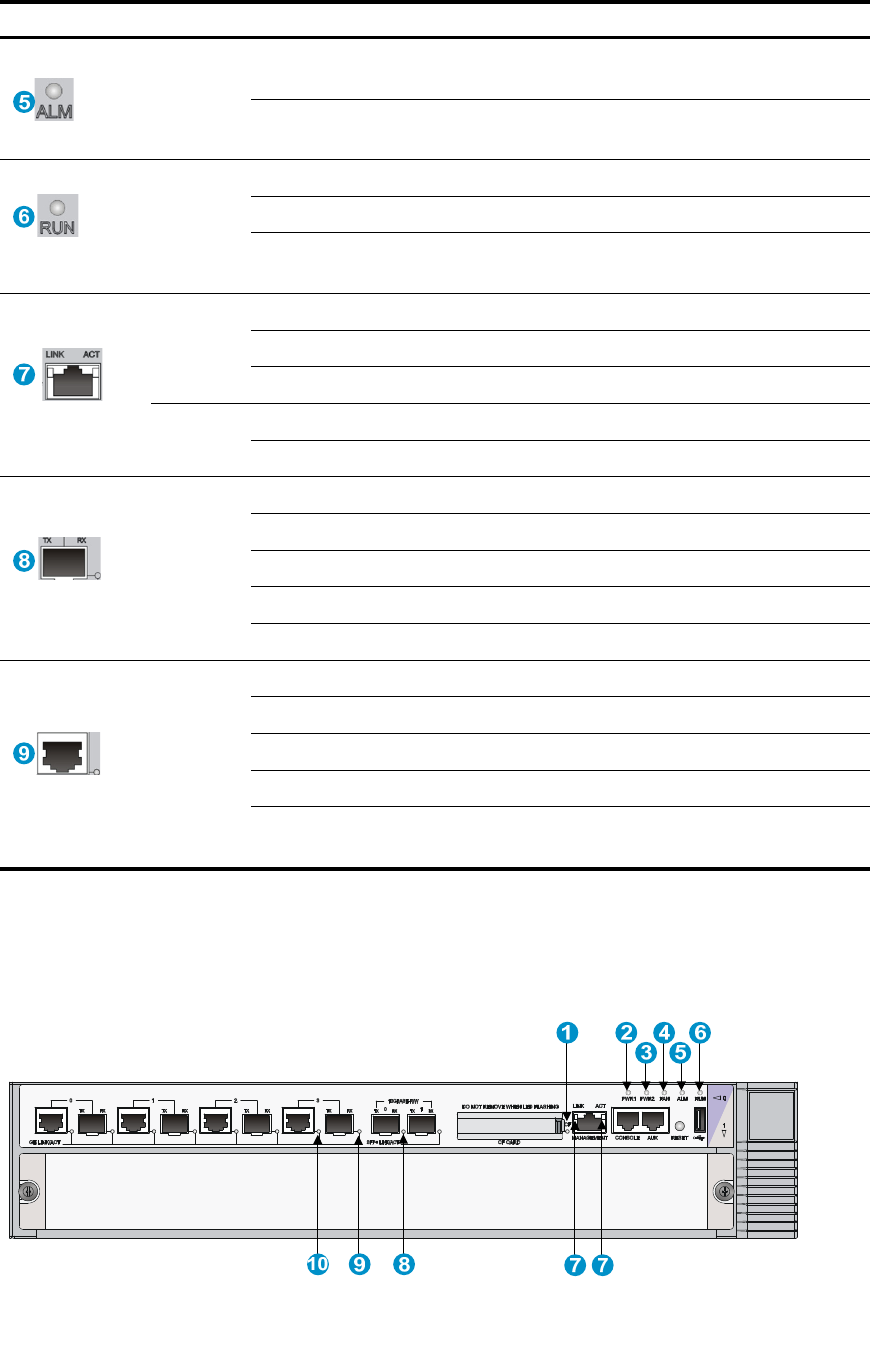
85
LED Status
Descri
p
tion
(red) ALM
Off The system is operating properly and there is no
alarm.
Steady red A fault has occurred. In this state, check the system log
immediately.
(green)
RUN
Off The system is powered off or the router is faulty.
Flashing at 1 Hz The router operates properly as configured.
Flashing at 8 Hz Software is being loaded or the router does not start
working yet.
(yellow/green)
LINK
Off The corresponding interface is not connected.
Steady green A 1000 Mbps link is present.
Steady yellow A 10/100 Mbps link is present.
ACT Off No data is being received or transmitted.
Flashing yellow Data is being received or transmitted.
(yellow/green)
SFP0
through
SFP3
Off No link is present.
Steady green A 1000 Mbps link is present.
Flashing green Data is being received or transmitted at 1000 Mbps.
Steady yellow A 100 Mbps link is present.
Flashing yellow Data is being received or transmitted at 100 Mbps.
(yellow/green)
GE0
through
GE3
Off No link is present.
Steady green A 1000 Mbps link is present.
Flashing green Data is being received or transmitted at 1000 Mbps.
Steady yellow A 10/100 Mbps link is present.
Flashing yellow Data is being received or transmitted at 10/100
Mbps.
HSR6602-XG/HSR6602-XG TAA panel LEDs
Figure 74 HSR6602-XG/HSR6602-XG TAA front view

86
Table 42 HSR6602-XG/HSR6602-XG TAA panel LED description
LED Status
Descri
p
tion
(yellow/green)
CF
Off No CF card is in position or the CF card cannot be
recognized.
Steady green A CF card is in position and has been detected.
Flashing green The system is accessing the CF card. In this state, do
not remove the CF card.
Steady yellow It is a non HP CF card.
(red/green)
PWR1
Off The power module is not in position.
Steady green The power module is supplying power properly.
Steady red No power is input or the power module is faulty
when PWR2 is operating properly.
(red/green)
PWR2
Off The power module is not in position.
Steady green The power module is supplying power properly.
Steady red No power is input or the power module is faulty
when PWR1 is operating properly.
(red/green)
FAN
Off No power is input or the fan tray is not in position.
Steady green The fan tray is working properly.
Steady red The fan tray is faulty.
(red) ALM
Off The system is operating properly and there is no
alarm.
Steady red A fault has occurred. In this state, check the system
log immediately.
(green)
RUN
Off The system is powered off or the router is faulty.
Flashing at 1 Hz
The router operates properly as configured.
Flashing at 8 Hz
Software is being loaded or the router does not start
working yet.
(yellow/green)
MANAGEME
NT
Off No link is present.
Steady green A 1000 Mbps link is present.
Flashing green Data is being received or transmitted at 1000 Mbps.
Steady yellow A 10/100 Mbps link is present.
Flashing yellow Data is being received or transmitted at 10/100
Mbps.
(yellow/green)
SFP+LINK/AC
T
Off No link is present.
Steady green A 10 Gbps link is present.
Flashing green Data is being received or transmitted at 10 Gbps.
Steady yellow The transceiver module check is not passed.
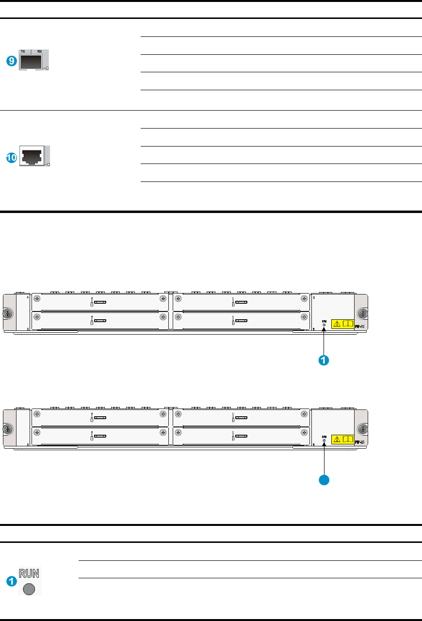
87
LED Status
Descri
p
tion
(yellow/green)
SFP0 through
SFP3
Off No link is present.
Steady green A 1000 Mbps link is present.
Flashing green Data is being received or transmitted at 1000 Mbps.
Steady yellow A 100 Mbps link is present.
Flashing yellow Data is being received or transmitted at 100 Mbps.
(yellow/green)
GE0 through
GE3
Off No link is present.
Steady green A 1000 Mbps link is present.
Flashing green Data is being received or transmitted at 1000 Mbps.
Steady yellow A 10/100 Mbps link is present.
Flashing yellow Data is being received or transmitted at 10/100
Mbps.
FIP LEDs
Figure 75 FIP-10 LED
Figure 76 FIP-20 LED
Table 43 FIP LED description
LED Status Descri
p
tion
(green)
Off No power input is available or the FIP has failed.
Flashing at 1 Hz The FIP is working properly.
Flashing at 8 Hz
Application software is being loaded (in this case, never power
off the router or hot-swap the FIP; otherwise, the FIP may be
damaged).
1
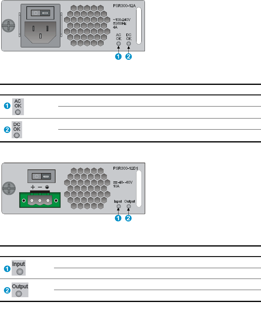
88
HIM/MIM LEDs
For description of HIM/MIM LEDs, see HP A6600 Router Series Interface Module Guide.
Power module LEDs
Figure 77 AC power module LED
Table 44 AC power module LED description
LED Status Descri
p
tion
(green)
Off No power is input or the power module has an input problem.
Steady green The power input is normal.
(green)
Off No power is output or the power module has an output problem.
Steady green The power output is normal.
Figure 78 DC power module LED
Table 45 DC power module LED description
LED Status Descri
p
tion
(green)
Off No power is input or the power module has an input problem.
Steady green The power input is normal.
(green)
Off No power is output or the power module has an output problem.
Steady green The power output is normal.

89
Appendix C Cable management
When an HSR6600 router is mounted in a 19-inch standard rack, the interface cables are routed through
the cable management brackets, bound at cabling racks on chassis sides, and then routed up or down,
depending on the available equipment room condition. The power cables run along the two sides of the
chassis and out of the chassis either from the chassis top or the raised floor depending on the equipment
room conditions (power distribution cabinet, lightning protection box, and connector strip, etc.) of the
exchange office.
General cabling requirements
Minimum curvature radius of cables
• The curvature radius of a fixed power cable, communication cable, or ribbon cable should be at
least five times the cable’s outer diameter. If the cable is frequently bent, plugged, and unplugged,
the curvature radius should be at least seven times the cable’s outer diameter.
• The curvature radius of an ordinary fixed coaxial cable should be at least seven times of the cable’s
outer diameter. If the coaxial cable is frequently bent, plugged, and unplugged, the curvature
radius should be at least 10 times the cable’s outer diameter.
• The curvature radius of a high-speed cable (for example, SFP+ cable) should be at least five times
of the cable’s outer diameter. If the coaxial cable is frequently bent, plugged and unplugged, the
curvature radius should be at least 10 times the cable’s outer diameter.
Minimum curvature radius of fibers
• When the fiber is wrapped up around the cabling plate, the diameter of the cabling plate should
be at least 25 times the fiber’s diameter.
• When the fiber is being moved, the curvature radius of the fiber should be at least 20 times the
fiber’s diameter.
• When the fiber is fixed, the curvature radius of the fiber should be at least 10 times the fiber’s
diameter.
NOTE:
The fiber’s diameter refers to the outer diameter of the fiber jacket. Typically, the diameter of a single-core
fiber is 0.9 mm (0.04 in), 2.0 mm (0.08 in), or 3.0 mm (0.12 in).
Labeling cables
Label cables before you route or bundle them. Labels are typically affixed 20 mm (0.79 in) to cable
plugs.
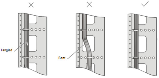
90
Cable management guidelines
When you route and bundle up cables, follow these guidelines:
• Bind and route the cables neatly inside the rack, and make sure that the cables are not kinked or
bent.
Figure 79 Correct and incorrect cable binding
• The cable bend radius at connectors must be at least 5 times the cable diameter, and must be at
least twice the cable diameter away from the connectors.
• Route different types of cables (for example, power cables, and signal cables) separately. If they are
close to one another, cross them over one another. If you route them in parallel, make sure that the
space between a power cable bundle and a signal cable bundle is at least 30 mm (1.18 in).
• The cable management brackets and cable routing slots, inside or outside the rack, are smooth and
have no sharp edges or tips.
• When you route cables through sharp sheet metal penetration points or along sharp edges of
mechanical parts, use bushings or take any other action to protect the cables from being cut or
abraded. The sheet metal penetration points must be smooth and fully rounded.
• Use the correct ties to bind the cables. Do not bind cables with joined ties. The following types of
ties are available: 100 × 2.5 mm (3.94 × 0.10 in), 150 × 3.6 mm (5.91 × 0.14 in), 300 × 3.6 mm
(11.81 × 0.14 in), 530 × 9 mm (20.87 × 0.35 in), and 580 × 13 mm (22.83 × 0.51 in).
• After binding the cables, cut the excess from the ties, leaving no sharp or angular tips. See Figure
80.
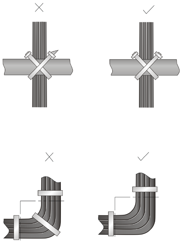
91
Figure 80 Cutting the cable ties
• When you bend cables, bind cables as shown in Figure 81. To avoid cable core break due to
excessive stress, do not tie up the cables in the bending area.
Figure 81 Binding the cables
• Route, bind, and attach excess cables for easy, safe maintenance activities and proper operations.
• Do not tie the power cables to the slide rails.
• When you connect a cable to an articulated part, for example, when you connect a grounding
cable to a cabinet door, leave enough slack in cables and make sure they are not stressed from any
movement of the part.
• Cables must be protected at points where they might rub or come in contact with sharp edges or
heated areas. Use high temperature cables near heat sources.
• Securely fasten cables and take adequate measures to prevent loose connections.
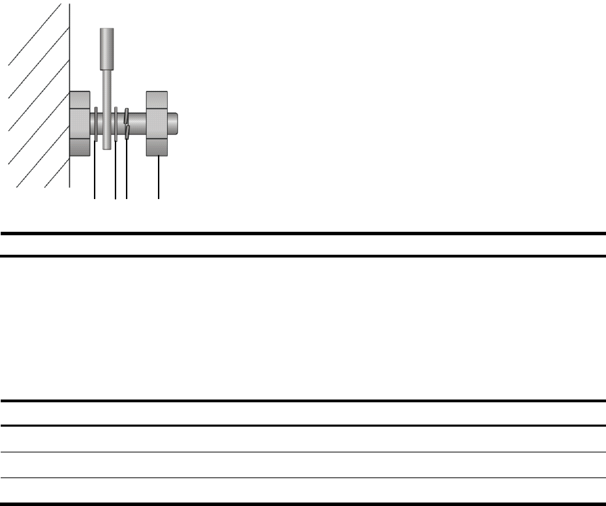
92
Figure 82 Securely fasten cables
(1) Flat washer (2) Sprin
g
washer
(3) Nut
• Fasten heavy or rigid power cables at the connectors to relief stress.
• Do not use tapping screws to fasten the connecting terminals.
• Bind together cables that are the same type and routed in the same direction.
Table 46 lists the cable bundling specifications.
Table 46 Cable bundling specifications
Cable bundle diameter (mm) S
p
ace between bundles (mm)
10 80 to 150
10 to 30 150 to 200
30 200 to 300
• Do not tie cables or bundles in a knot.
• The metal parts of the crimped cold-pressed terminal blocks (such as circuit breaker) cannot
protrude beyond the blocks.
Cable routing example
Cables on an HSR6600 router can be routed as shown in Figure 83.
(1) (1)(2) (3)
(1) (1)(2) (3)
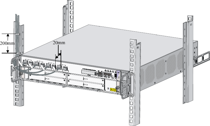
93
Figure 83 Routing cables
A01-03-01
A01-03-02
A01-03-03
A01-03-04
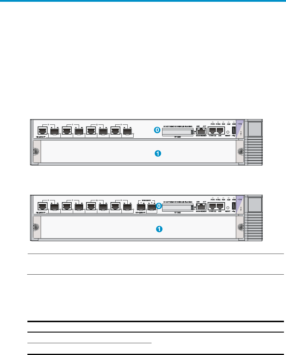
94
Appendix D Arranging slots and numbering
interfaces
Slot arrangement
The router provides many types of interfaces, such as console, AUX, GigabitEthernet, serial (synchronous)
and E1 ports. This chapter describes how these interfaces are numbered.
Figure 84 Slot arrangement on the SR6602-X1
Figure 85 Slot arrangement on the SR6602-X2
NOTE:
The numbers in Figure 84 and Figure 85 represent corresponding slot numbers.
Slot arrangement for FIPs
Table 47 Slot arrangement for FIPs
FIPs Slot arran
g
ement
FIP-10 Slot 1
FIP-20

95
Numbering interfaces
Before installing a HIM/MIM, you must install a FIP. A FIP20 supports both HIMs and MIMs, while a
FIP-10 supports only MIMs.
The interfaces of the router are numbered in the form of interface-type X/Y/Z,
Where,
• interface-type: Type of the interface such as GE port and serial port.
• X: Number of the slot where the FIP resides.
• Y: Sub-slot number—The number of the slot where the HIM/MIM resides on the FIP.
• Z: Sequence number of the interface on the HIM/MIM.
NOTE:
• Different interface modules on the same FIP have the same slot number X.
• Different interfaces on the same HIM/MIM have the same sub-slot number Y.
• For each type of interface, the sequence number Z starts from 0 on the interface module.
Examples
Example 1
A FIP-10 is installed in slot 1 and a MIM-2GBE module is installed on the FIP-10.
1. If the MIM-2GBE is installed in slot 1 of the FIP-10, the GigabitEthernet interfaces are:
• GigabitEthernet 1/1/0
• GigabitEthernet 1/1/1
2. If the MIM-2GBE is installed in slot 2 of the FIP-10/FIP-100/FIP-110, the GigabitEthernet interfaces
are:
• GigabitEthernet 1/2/0
• GigabitEthernet 1/2/1
Example 2
A FIP-20 is installed in slot 1 and a HIM-4GBE module is installed on the FIP20.
1. If the HIM-4GBE is installed in slot 1 of the FIP20, the GigabitEthernet interfaces are:
• GigabitEthernet 1/1/0
• GigabitEthernet 1/1/1
• GigabitEthernet 1/1/2
• GigabitEthernet 1/1/3
2. If the HIM-4GBE is installed in slot 2 of the FIP20, the GigabitEthernet interfaces are:
• GigabitEthernet 1/2/0
• GigabitEthernet 1/2/1
96
• GigabitEthernet 1/2/2
• GigabitEthernet 1/2/3

97
Support and other resources
Contacting HP
For worldwide technical support information, see the HP support website:
http://www.hp.com/support
Before contacting HP, collect the following information:
• Product model names and numbers
• Technical support registration number (if applicable)
• Product serial numbers
• Error messages
• Operating system type and revision level
• Detailed questions
Subscription service
HP recommends that you register your product at the Subscriber's Choice for Business website:
http://www.hp.com/go/wwalerts
After registering, you will receive email notification of product enhancements, new driver versions,
firmware updates, and other product resources.
Related information
Documents
To find related documents, browse to the Manuals page of the HP Business Support Center website:
http://www.hp.com/support/manuals
• For related documentation, navigate to the Networking section, and select a networking category.
• For a complete list of acronyms and their definitions, see HP FlexNetwork Technology Acronyms.
Websites
• HP.com http://www.hp.com
• HP Networking http://www.hp.com/go/networking
• HP manuals http://www.hp.com/support/manuals
• HP download drivers and software http://www.hp.com/support/downloads
• HP software depot http://www.software.hp.com
• HP Education http://www.hp.com/learn
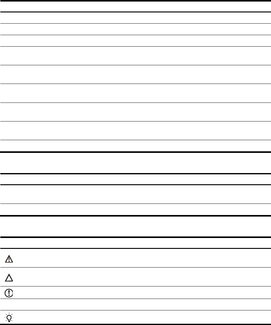
98
Conventions
This section describes the conventions used in this documentation set.
Command conventions
Convention Descri
p
tion
Boldface Bold text represents commands and keywords that you enter literally as shown.
Italic Italic text represents arguments that you replace with actual values.
[ ] Square brackets enclose syntax choices (keywords or arguments) that are optional.
{ x | y | ... }
Braces enclose a set of required syntax choices separated by vertical bars, from which
you select one.
[ x | y | ... ]
Square brackets enclose a set of optional syntax choices separated by vertical bars, from
which you select one or none.
{ x | y | ... } *
Asterisk-marked braces enclose a set of required syntax choices separated by vertical
bars, from which you select at least one.
[ x | y | ... ] *
Asterisk-marked square brackets enclose optional syntax choices separated by vertical
bars, from which you select one choice, multiple choices, or none.
&<1-n> The argument or keyword and argument combination before the ampersand (&) sign can
be entered 1 to n times.
# A line that starts with a pound (#) sign is comments.
GUI conventions
Convention Descri
p
tion
Boldface Window names, button names, field names, and menu items are in bold text. For
example, the New User window appears; click OK.
> Multi-level menus are separated by angle brackets. For example, File > Create > Folder.
Symbols
Convention Descri
p
tion
WARNING An alert that calls attention to important information that if not understood or followed can
result in personal injury.
CAUTION An alert that calls attention to important information that if not understood or followed can
result in data loss, data corruption, or damage to hardware or software.
IMPORTANT An alert that calls attention to essential information.
NOTE An alert that contains additional or supplementary information.
TIP An alert that provides helpful information.
99
Network topology icons
Represents a generic network device, such as a router, switch, or firewall.
Represents a routing-capable device, such as a router or Layer 3 switch.
Represents a generic switch, such as a Layer 2 or Layer 3 switch, or a router that supports
Layer 2 forwarding and other Layer 2 features.
Represents an access controller, a unified wired-WLAN module, or the switching engine
on a unified wired-WLAN switch.
Represents an access point.
Represents a security product, such as a firewall, a UTM, or a load-balancing or security
card that is installed in a device.
Represents a security card, such as a firewall card, a load-balancing card, or a
NetStream card.
Port numbering in examples
The port numbers in this document are for illustration only and might be unavailable on your device.

100
Index
A C D E F G H I L N P R S U
A
Accessories,7
Application file missing errors,71
C
Cable management guidelines,90
Cable routing example,92
Chassis views,73
Check before installation,8
Configuration system problems,63
Configuring a combo interface,54
Configuring basic settings,39
Connecting a CE3/CT3 cable,28
Connecting a fiber cable,21
Connecting a serial port cable,29
Connecting an E1/T1 cable,25
Connecting an Ethernet cable,19
Connecting the AUX cable,18
Connecting the power cord,16
Contacting HP,97
Conventions,98
Cooling system failure,69
D
Dealing with password loss,64
Dimensions and weights,74
Displaying hardware information of the router,49
Displaying the alarming thresholds of a module,54
Displaying the initial configuration,39
Displaying transceiver module information and
alarming information,56
E
Examining the installation site,2
Examples,95
F
Fan failures,62
Fan tray,77
FIP LEDs,87
FIP module failure,61
Flexible interface platform modules,81
G
General cabling requirements,89
Grounding the router,11
H
HIM/MIM failures,63
HIM/MIM LEDs,88
I
Installation flow,8
Installing a CF card,15
Installing a FIP module,13
Installing a HIM/MIM,14
Installing a power module,13
Installing the router in a 19-inch rack,9
Interface module, cable, and connection failure,70
Interface modules,83
L
Labeling cables,89
Logging in through the console port,33
Logging in to the router through Telnet/SSH,38
Logging in to the router through the AUX port,38
Login methods,33
N
Numbering interfaces,95
P
Panel LEDs,84
Port specifications,78
Power consumption,75
Power module,75
Power module failures,61
Power module LEDs,88
R
Rebooting the router,58
Related information,97
101
Replacing a CF card,43
Replacing a fan tray,45
Replacing a FIP module,42
Replacing a HIM/MIM,42
Replacing a memory module,46
Replacing a power module,41
Replacing a transceiver module,44
Router failures,60
S
Safety recommendations,41
Safety recommendations,1
Saving the current configuration of the router,58
Slot arrangement,94
Slot arrangement for FIPs,94
Software upgrade failures,70
Solving system faults,57
Storage media,75
U
Unpacking the router,9
