Hp Pavilion Ze4400 Users Manual Service
PAVILION ZE4600 service_manual_for_HP_Pavilion_ZE4400_7cc234202e_PAVILLION ze4400 SM
ZE5600 to the manual fa0a1cb4-91a6-4495-b306-a1aba453d39d
2015-02-09
: Hp Hp-Pavilion-Ze4400-Users-Manual-547225 hp-pavilion-ze4400-users-manual-547225 hp pdf
Open the PDF directly: View PDF ![]() .
.
Page Count: 153 [warning: Documents this large are best viewed by clicking the View PDF Link!]
- Contents
- Introduction
- Product Information
- Removal and Replacement
- Disassembly Flowchart
- Removing the Battery
- Removing an SDRAM Module
- Removing the Wireless LAN Mini PCI Card
- Removing the Hard Disk Drive
- Recovering the Factory Software
- Replacing Small Parts
- Removing the Keyboard Cover
- Removing the Speaker Assembly
- Removing the Keyboard
- Removing the Switchboard PCA
- Removing the CD/DVD Drive
- Removing the Display Assembly
- Removing the Top Case
- Removing the Floppy Drive
- Removing the Infrared (I/R) PCA
- Removing the Audio PCA
- Removing the Heat Sink (with Fan)
- Removing the CPU Module
- Removing the RJ11/1394 Connector Module
- Removing the Motherboard
- Replacing Components on a Bottom Case
- Repairing the BIOS IC
- Removing Other Components
- Troubleshooting and Diagnostics
- Replaceable Parts
- Reference Information
Service Manual i
HP Pavilion ze5600 Notebook PC
HP Pavilion ze5500 Notebook PC
HP Pavilion ze5400 Notebook PC
HP Pavilion ze5300 Notebook PC
HP Pavilion ze5200 Notebook PC
HP Pavilion ze4600 Notebook PC
HP Pavilion ze4500 Notebook PC
HP Pavilion ze4400 Notebook PC
HP Pavilion ze4300 Notebook PC
HP Pavilion ze4200 Notebook PC
HP Pavilion ze4100 Notebook PC
HP nx9010 Notebook PC
HP nx9008 Notebook PC
HP nx9005 Notebook PC
HP nx9000 Notebook PC
Compaq Evo Notebook N1050v Series
Compaq Evo Notebook N1010v Series
Compaq Presario 2500 Series Mobile PC
Compaq Presario 2100 Series Mobile PC
Compaq Presario 1100 Series Mobile PC
Technology Code KE
Service Manual


ii Service Manual
© Copyright 2003, 2004 Hewlett-Packard Development Company, L.P.
Microsoft and Windows are U.S. registered trademarks of Microsoft Corporation. Intel ,Celeron, and
Pentium are trademarks or registered trademarks of Intel Corporation or its subsidiaries in the United States
and other countries.
The information contained herein is subject to change without notice. The only warranties for HP products
and services are set forth in the express warranty statements accompanying such products and services.
Nothing herein should be construed as constituting an additional warranty. HP shall not be liable for
technical or editorial errors or omissions contained herein.
Service Manual
Third Edition February 2004
First Edition January 2003
Document Part Number: 319733-003

Service Manual iii
Contents
Introduction..................................................................................................................... vii
Product Information...................................................................................................... 1-1
Features ................................................................................................................................................ 1-8
Operation............................................................................................................................................ 1-14
Specifications ..................................................................................................................................... 1-18
Internal Design................................................................................................................................... 1-24
Removal and Replacement............................................................................................ 2-1
Disassembly Flowchart ........................................................................................................................ 2-3
Removing the Battery .......................................................................................................................... 2-4
Removing an SDRAM Module............................................................................................................ 2-5
Removing the Wireless LAN Mini PCI Card ...................................................................................... 2-7
Removing the Hard Disk Drive............................................................................................................ 2-9
Recovering the Factory Software....................................................................................................... 2-11
Replacing Small Parts ........................................................................................................................ 2-12
Removing the Keyboard Cover.......................................................................................................... 2-13
Removing the Speaker Assembly ...................................................................................................... 2-15
Removing the Keyboard .................................................................................................................... 2-16
Removing the Switchboard PCA ....................................................................................................... 2-19
Removing the CD/DVD Drive........................................................................................................... 2-20
Removing the Display Assembly....................................................................................................... 2-23
Removing the Top Case..................................................................................................................... 2-26
Removing the Floppy Drive............................................................................................................... 2-32
Removing the Infrared (I/R) PCA...................................................................................................... 2-36
Removing the Audio PCA ................................................................................................................. 2-38
Removing the Heat Sink (with Fan)................................................................................................... 2-40
Removing the CPU Module............................................................................................................... 2-44
Removing the RJ11/1394 Connector Module.................................................................................... 2-48
Removing the Motherboard ............................................................................................................... 2-50
Replacing Components on a Bottom Case......................................................................................... 2-59
Repairing the BIOS IC....................................................................................................................... 2-61
Removing Other Components............................................................................................................ 2-63
Troubleshooting and Diagnostics ................................................................................. 3-1
Support by Authorized Service Providers............................................................................................ 3-2
Troubleshooting ................................................................................................................................... 3-3
Diagnostic Tools ................................................................................................................................ 3-18
Replaceable Parts........................................................................................................... 4-1
Reference Information .................................................................................................. 5-1
Password Removal Policy.................................................................................................................... 5-2
Hewlett-Packard Display Quality Statement........................................................................................ 5-3
Service Notes and Obsolete Parts ........................................................................................................ 5-5

iv Service Manual
Figures
Figure 1-1. Front View................................................................................................................................ 1-8
Figure 1-2. Back View ................................................................................................................................ 1-9
Figure 1-3. Bottom View........................................................................................................................... 1-10
Figure 1-4. Front View.............................................................................................................................. 1-11
Figure 1-5. Back View .............................................................................................................................. 1-12
Figure 1-6. Bottom View........................................................................................................................... 1-13
Figure 1-7. Resetting the Notebook .......................................................................................................... 1-17
Figure 1-8. Replaceable Module Diagram ................................................................................................ 1-24
Figure 2-1. Disassembly Flow..................................................................................................................... 2-3
Figure 2-2. Removing the Battery............................................................................................................... 2-4
Figure 2-3. Removing an SDRAM Module ................................................................................................ 2-5
Figure 2-4. Removing an SDRAM Module ................................................................................................ 2-6
Figure 2-5. Removing the Mini PCI Card................................................................................................... 2-7
Figure 2-6. Removing the Mini PCI Card................................................................................................... 2-8
Figure 2-7. Removing the Hard Disk Drive ................................................................................................ 2-9
Figure 2-8. Removing the Hard Disk Drive Tray...................................................................................... 2-10
Figure 2-9. Removing the Keyboard Cover .............................................................................................. 2-14
Figure 2-10. Disconnecting the Speaker Cable ......................................................................................... 2-14
Figure 2-11. Removing the Speaker Assembly......................................................................................... 2-15
Figure 2-12. Removing the Keyboard....................................................................................................... 2-17
Figure 2-13. Removing the Switchboard PCA.......................................................................................... 2-18
Figure 2-14. Removing the Switchboard PCA.......................................................................................... 2-19
Figure 2-15. Removing the CD/DVD Drive ............................................................................................. 2-21
Figure 2-16. Removing the CD/DVD Drive ............................................................................................. 2-22
Figure 2-17. Removing the Display Assembly ......................................................................................... 2-24
Figure 2-18. Removing the Top Case........................................................................................................ 2-27
Figure 2-19. Removing the Top Case Screws........................................................................................... 2-29
Figure 2-20. Removing the Top Case Screws........................................................................................... 2-30
Figure 2-21. Removing the Top Case........................................................................................................ 2-31
Figure 2-22. Removing the Floppy Drive ................................................................................................. 2-33
Figure 2-23. Removing the Floppy Drive ................................................................................................. 2-35
Figure 2-24. Removing the I/R PCA......................................................................................................... 2-37
Figure 2-25. Removing the Audio PCA.................................................................................................... 2-39
Figure 2-26. Removing the Heat Sink (with Fan) ..................................................................................... 2-41
Figure 2-27. Removing the Heat Sink (with Fan) ..................................................................................... 2-43
Figure 2-28. Removing the CPU Module.................................................................................................. 2-45
Figure 2-29. Removing the CPU Module.................................................................................................. 2-47
Figure 2-30. Removing the RJ11/1394 Connector Module ...................................................................... 2-49
Figure 2-31. Removing the Motherboard.................................................................................................. 2-51
Figure 2-32. Removing the Hard Disk Drive Guide .................................................................................2-53
Figure 2-33. Disconnecting the Motherboard Cables................................................................................ 2-54
Figure 2-34. Removing the Motherboard.................................................................................................. 2-56
Figure 2-35. Example of Serial Number Label ......................................................................................... 2-59
Figure 2-36. Replacing the Antennas ........................................................................................................ 2-60
Figure 2-37. Removing a PCMCIA Door ................................................................................................. 2-60
Figure 2-38. Boot-Block Jumper............................................................................................................... 2-62
Figure 3-1. Basic Troubleshooting Steps .................................................................................................... 3-3
Figure 4-1. Exploded View ......................................................................................................................... 4-2
Figure 4-2. Exploded View ......................................................................................................................... 4-3

Service Manual v
Tables
Table 1-1. Product Comparisons................................................................................................................. 1-1
Table 1-2. Activating Power Modes ......................................................................................................... 1-14
Table 1-3. Main Status Lights (front of notebook) ................................................................................... 1-15
Table 1-4. Keyboard Status Lights............................................................................................................ 1-15
Table 1-5. Fn Hot Keys............................................................................................................................. 1-16
Table 1-6. Specifications........................................................................................................................... 1-18
Table 1-7. Accessories .............................................................................................................................. 1-22
Table 1-8. Functional Structure Description ............................................................................................. 1-25
Table 2-1. Removal Cross-Reference ......................................................................................................... 2-1
Table 2-2. Required Equipment .................................................................................................................. 2-2
Table 2-3. Recommended Screw Torque Values........................................................................................ 2-2
Table 2-4. Replacing Small Parts.............................................................................................................. 2-12
Table 2-5. Removing Components............................................................................................................ 2-63
Table 3-1. ASP Support Options................................................................................................................. 3-2
Table 3-2. Scope of Diagnostic Tools......................................................................................................... 3-7
Table 3-3. Troubleshooting Suggestions..................................................................................................... 3-8
Table 3-4. POST Terminal-Error Beep Codes .......................................................................................... 3-20
Table 3-5. POST Messages ....................................................................................................................... 3-24
Table 3-6. Sycard PCCtest Commands ..................................................................................................... 3-26
Table 3-7. BIOS Setup Menus and Parameters......................................................................................... 3-28
Table 4-1. Replaceable Parts....................................................................................................................... 4-4
Table 4-2. Accessory Replaceable Parts ................................................................................................... 4-11
Table 4-3. Part Number Reference............................................................................................................ 4-12
Table 5-1. LCD Guidelines ......................................................................................................................... 5-4
Service Manual vii
Introduction
This manual provides reference information for servicing the HP Pavilion ze5600, ze5500, ze5400,
ze5300, ze5200, ze4600, ze4500, ze4400, ze4300, ze4200, and ze4100 Notebook PCs, HP nx9010,
nx9008, nx9005, and nx9000 Notebook PCs, Compaq Evo Notebook 1050v and 1010v Series, and
Compaq Presario 2500, 2100, and 1100 Series Mobile PCs. These notebook models use technology code
KE. This manual is for use by authorized service personnel while installing, servicing, and repairing these
products.
The manual is designed as a self-paced guide that will train you to install, configure, and repair these
notebooks. The manual is self-contained, so you can follow it even without having equipment available.
The following table lists other sources of information about the notebook computers and related products.
Source Address or Number Comments
HP Notebook Web site
Compaq Notebook Web site
http://www.hp.com/notebooks
http://welcome.hp.com/country/us/eng/prodserv/
notebooks_tabletpcs.html
HP Business Support Web site http://www.hp.com/go/bizsupport
HP Asia Pacific Channel Support
Centre for DPSP Partners http://www.hp.com.au/ Restricted to DPSP
Partners only.
America Online Keyword: HP Call (800) 827-6364
for membership within the
US.
CompuServe GO HP Call (800) 524-3388
for membership within
the U.S.
HP Support Assist
CD-ROM
(800) 457-1762 U.S. and Canada.
(801) 431-1587 Outside US and Canada.
Microsoft® Windows® manual Information about
Windows operating
system.
Microsoft Web site http://www.microsoft.com/ Information and updates
for Windows operating
systems.
Service Manual Product Information 1-1
1
Product Information
The following list of HP and Compaq notebook products is current at the time of publication but is subject
to change.
Table 1-1. Product Comparisons
HP Pavilion ze5600
Processor Intel® Celeron® (2.6-, 2.8-GHz)
Mobile Intel Pentium® 4 (2.4-, 2.66-, 2.8-, and 3.06-GHz)
Memory Up to 1 GB (1024 MB) SDRAM using 512-MB modules. At least 256 MB SDRAM preinstalled.
Display 15.0-inch XGA (1024 × 768) or SXGA+ (1024 × 768) active-matrix TFT
Video ATI Mobility Radeon graphics accelerator with 16, 32, or 64 MB UMA graphics memory, 4x AGP graphics
capability
Operating System Microsoft® Windows® XP Professional or Windows XP Home preinstalled
Power States On, Standby, Hibernate, Off
HP Pavilion ze5500
Processor Intel Celeron (2.6-GHz)
Mobile Intel Pentium 4 (2.4-, 2.66-, 2.8-, and 3.06-GHz)
Memory Up to 1 GB (1024 MB) SDRAM using 512-MB modules. At least 256 MB SDRAM preinstalled.
Display 15.0-inch XGA (1024 × 768) or SXGA+ (1400 × 1050) or 14.1-inch XGA (1024 × 768) active-matrix TFT
Operating System Windows XP Professional or Windows XP Home preinstalled
Power States On, Standby, Hibernate, Off
1-2 Product Information Service Manual
HP Pavilion ze5400 and ze5300
Processor Intel Pentium 4 (2.4-, 2.53-, 2.66-, and 2.8-GHz)
Mobile Intel Pentium 4 (2.4-, 2.66-, 2.8-, and 3.06-GHz)
Memory Up to 1 GB (1024 MB) SDRAM using 512-MB modules. At least 256 MB SDRAM preinstalled.
Display 15.0-inch XGA (1024 × 768) or SXGA+ (1400 × 1050) or 14.1-inch XGA (1024 × 768) active-
matrix TFT
Video ATI Mobility Radeon graphics accelerator with 16, 32, or 64 MB UMA graphics memory, 4x AGP
graphics capability
Operating System Windows XP Professional or Windows XP Home preinstalled
Power States On, Standby, Hibernate, Off
HP Pavilion ze5200
Processor Mobile Intel Pentium 4 (2.4-, 2.53-, 2.66-, and 2.8-GHz)
Memory Up to 1 GB (1024 MB) SDRAM using 512-MB modules. At least 256 MB SDRAM preinstalled.
Display 15.0-inch XGA (1024 × 768) or SXGA+ (1400 × 1050) or
14.1-inch XGA (1024 × 768) active-matrix TFT
Video ATI Mobility Radeon graphics accelerator with 16, 32, or 64 MB UMA graphics memory, 4x AGP
graphics capability.
Operating System Windows XP Professional or Windows XP Home preinstalled
Power States On, Standby, Hibernate, Off
HP Pavilion ze4600
Processor AMD Athlon (1.47-, 1.53-, 1.67-, 1.8-, 2.2-, and 2.0-GHz)
Memory Up to 1 GB (1024 MB) SDRAM using 512-MB modules. At least 128 MB SDRAM preinstalled.
Display 15.0-inch XGA (1024 × 768) or SXGA+ (1400 × 1050) or
14.1-inch XGA (1024 × 768) active-matrix TFT
Video ATI Mobility Radeon graphics accelerator with 16, 32, or 64 MB UMA graphics memory, 4x AGP
graphics capability
Operating System Windows XP Professional or Windows XP Home preinstalled
Power States On, Standby, Hibernate, Off

Service Manual Product Information 1-3
HP Pavilion ze4500
Processor AMD Athlon (1.67-, 1.8-, 2.2-, and 2.0-GHz)
Intel Celeron (2.4-GHz)
Memory Up to 1 GB (1024 MB) SDRAM using 512-MB modules. At least 128 MB SDRAM preinstalled.
Display 15.0-inch XGA (1024 × 768) or 14.1-inch XGA (1024 × 768) active-matrix TFT
Video ATI Mobility Radeon graphics accelerator with 16, 32, or 64 MB UMA graphics memory, 4x AGP
graphics capability
Operating System Windows XP Professional or Windows XP Home preinstalled
Power States On, Standby, Hibernate, Off
HP Pavilion ze4400
Processor AMD Athlon (1.47-, 1.53-, 1.67-, 1.8-, 2.2-, and 2.0-GHz)
Memory Up to 1 GB (1024 MB) SDRAM using 512-MB modules. At least 128 MB SDRAM preinstalled.
Display 15.0-inch XGA (1024 × 768) or 14.1-inch XGA (1024 × 768) active-matrix TFT
Video ATI Mobility Radeon graphics accelerator with 16, 32, or 64 MB UMA graphics memory, 4x AGP
graphics capability
Operating System Windows XP Professional or Windows XP Home preinstalled.
Power States On, Standby, Hibernate, Off
HP Pavilion ze4300
Processor Mobile Intel Pentium 4 Processor-M (1.8-, 2.0-, 2.2-, and 2.4-GHz)
Intel Celeron (1.8-, 2.0-, and 2.2-GHz)
AMD Athlon (1.47-, 1.53-, 1.67-, 1.8-, 1.87-, and 2.0-GHz)
Memory Up to 1 GB (1024 MB) SDRAM using 512-MB modules. At least 128 MB SDRAM preinstalled.
Display 15.0-inch XGA (1024 × 768) or SXGA+ (1400 × 1050) or 14.1-inch XGA (1024 × 768) active-
matrix TFT
Video ATI Mobility Radeon graphics accelerator with 16, 32, or 64 MB UMA graphics memory, 4x AGP
graphics capability
Operating System Windows XP Professional or Windows XP Home preinstalled
Power States On, Standby, Hibernate, Off
1-4 Product Information Service Manual
HP Pavilion ze4200
Processor Mobile Intel Pentium 4 Processor-M (1.8-, 1.9-, 2.0-, and 2.2-GHz)
Intel Celeron (1.6-, 1.7-, 1.8-, and 2.0-GHz)
AMD Athlon (1.47-, 1.53-, 1.6-, 1.67-, and 1.8-GHz)
Memory Up to 512 MB SDRAM using 256-MB modules. At least 128 MB SDRAM preinstalled.
Display 15.0-inch XGA (1024 × 768) or SXGA+ (1400 × 1050) or 14.1-inch XGA (1024 × 768) active-matrix TFT
Video ATI Mobility Radeon graphics accelerator with 16, 32, or 64 MB UMA graphics memory, 4x AGP graphics
capability
Operating System Windows XP Professional or Windows XP Home preinstalled
Power States On, Standby, Hibernate, Off
HP Pavilion ze4100
Processor Mobile Intel Pentium 4 Processor-M (1.7-, 1.8-, and 2.0-GHz)
Intel Celeron (1.6-, 1.7-, and 1.8-GHz)
Memory Up to 1 GB (1024 MB) SDRAM using 512-MB modules. At least 128 MB SDRAM preinstalled.
Display 15.0-inch XGA (1024 × 768) or 14.1-inch XGA (1024 × 768) active-matrix TFT
Video ATI Mobility Radeon graphics accelerator with 16, 32, or 64 MB UMA graphics memory, 4x AGP graphics
capability.
Operating System Windows XP Professional or Windows XP Home preinstalled
Power States On, Standby, Hibernate, Off
Service Manual Product Information 1-5
HP nx9010
Processor Mobile Intel Pentium 4-D (2.4-, 2.53-, 2.66-, and 3.06-GHz)
Intel Celeron (2.0- and 2.6-GHz)
Memory Up to 1 GB (1024 MB) SDRAM using 512-MB modules. At least 256 MB SDRAM preinstalled.
Display 15.0-inch XGA (1024 × 768) or SXGA+ (1400 × 1050) active-matrix TFT
Video ATI Mobility Radeon graphics accelerator with 16, 32, or 64 MB UMA graphics memory, 4x AGP
graphics capability
Operating System Windows XP Professional or Windows XP Home preinstalled
Power States On, Standby, Hibernate, Off
HP nx9008
Processor Intel Celeron (2.6- and 2.8-GHz)
Memory At least 256 MB SDRAM preinstalled
Display 14.1-inch XGA (1024 × 768) active-matrix TFT
Video ATI Mobility Radeon graphics accelerator with 16, 32, or 64 MB UMA graphics memory, 4x AGP
graphics capability.
Operating System Windows XP Professional or Windows XP Home preinstalled
Power States On, Standby, Hibernate, Off
HP nx9005
Processor Mobile Intel Pentium 4 Processor-M (1.8-, 2.0-, 2.2-, and 2.4-GHz)
Intel Celeron (1.8-, 2.0-, and 2.2-GHz)
AMD Athlon (1.47-, 1.53-, 1.8-, and 2.0-GHz)
Memory Up to 1 GB (1024 MB) SDRAM using 512-MB modules. At least 128 MB SDRAM preinstalled.
Display 15.0-inch XGA (1024 × 768) or SXGA+ (1400 × 1050) or
14.1-inch XGA (1024 × 768) active-matrix TFT
Video ATI Mobility Radeon graphics accelerator with 16, 32, or 64 MB UMA graphics memory, 4x AGP
graphics capability
Operating System Windows XP Professional or Windows XP Home preinstalled
Power States On, Standby, Hibernate, Off
1-6 Product Information Service Manual
HP nx9000
Processor AMD Athlon (1.8- or 2.0-GHz)
Memory Up to 1 GB (1024 MB) SDRAM using 512-MB modules. At least 256 MB SDRAM preinstalled.
Display 15.0-inch XGA (1024 × 768) or SXGA+ (1400 × 1050) active-matrix TFT
Video ATI Mobility Radeon graphics accelerator with 16, 32, or 64 MB UMA graphics memory, 4x AGP
graphics capability
Operating System Windows XP Professional or Windows XP Home preinstalled
Power States On, Standby, Hibernate, Off
Compaq Evo Notebook N1050v
Processor Mobile Intel Pentium 4 Processor-M (1.8-GHz)
Intel Celeron (1.6-GHz)
Memory Up to 1 GB (1024 MB) SDRAM using 512-MB modules. At least 256 MB SDRAM preinstalled.
Display 15.0-inch XGA (1024 × 768) or 14.1-inch XGA (1024 × 768) active-matrix TFT
Video ATI Mobility Radeon graphics accelerator with 16, 32, or 64 MB UMA graphics memory, 4x AGP graphics
capability.
Operating System Windows XP Professional or Windows XP Home preinstalled
Power States On, Standby, Hibernate, Off
Compaq Evo Notebook 1010v
Processor Intel Celeron (1.6-GHz)
Memory Up to 1 GB (1024 MB) SDRAM using 512-MB modules. At least 128 MB SDRAM preinstalled.
Display 14.1-inch XGA (1024 × 768) active-matrix TFT
Video ATI Mobility Radeon graphics accelerator with 16, 32, or 64 MB UMA graphics memory, 4x AGP graphics
capability
Operating System Windows XP Professional or Windows XP Home preinstalled
Power States On, Standby, Hibernate, Off

Service Manual Product Information 1-7
Compaq Presario 2500
Processor Mobile Intel Pentium 4 (2.0-, 2.3-, 2.4-, 2.53-, 2.66-, 2.8-, and 3.06-GHz)
Intel Celeron (2.6- and 2.8-GHz)
Memory Up to 1 GB (1024 MB) SDRAM using 512-MB modules. At least 256 MB SDRAM preinstalled.
Display 15.0-inch XGA (1024 × 768) or SXGA+ (1400 × 1050) or
14.1-inch XGA (1024 × 768) active-matrix TFT
Video ATI Mobility Radeon graphics accelerator with 16, 32, or 64 MB UMA graphics memory, 4x AGP
graphics capability
Operating System Windows XP Professional or Windows XP Home preinstalled
Power States On, Standby, Hibernate, Off
Compaq Presario 2100
Processor Intel Pentium 4 Processor-M (1.8-, 1.9-, 2.0-, and 2.2-GHz)
Intel Pentium 4-D (2.53-GHz)
Intel Celeron (1.6-, 1.7-, 1.8-, 2.0-, and 2.4-GHz)
AMD Athlon (1.46-, 1.53-, 1.67-, and 1.8-GHz )
AMD Athlon XP-M (1.87-, 2.0-GHz)
Memory Up to 1 GB (1024 MB) SDRAM using 512-MB modules. At least 128 MB SDRAM preinstalled.
Display 15.0-inch XGA (1024 × 768) or SXGA+ (1400 × 1050) or
14.1-inch XGA (1024 × 768) active-matrix TFT
Video ATI Mobility Radeon graphics accelerator with 16, 32, or 64 MB UMA graphics memory, 4x AGP
graphics capability
Operating System Windows XP Professional or Windows XP Home preinstalled
Power States On, Standby, Hibernate, Off
Compaq Presario 1100
Processor Intel Celeron (1.6- and 1.8-GHz)
Memory Up to 512 MB SDRAM using 256-MB modules. At least 256 MB SDRAM preinstalled.
Display 15.0-inch XGA (1024 × 768) or SXGA+ 1400 × 1050) or
14.1-inch XGA (1024 × 768) active-matrix TFT
Video ATI Mobility Radeon graphics accelerator with 16, 32, or 64 MB UMA graphics memory, 4x AGP
graphics capability
Operating System Windows XP Professional or Windows XP Home preinstalled
Power States On, Standby, Hibernate, Off
1-8 Product Information Service Manual
Features
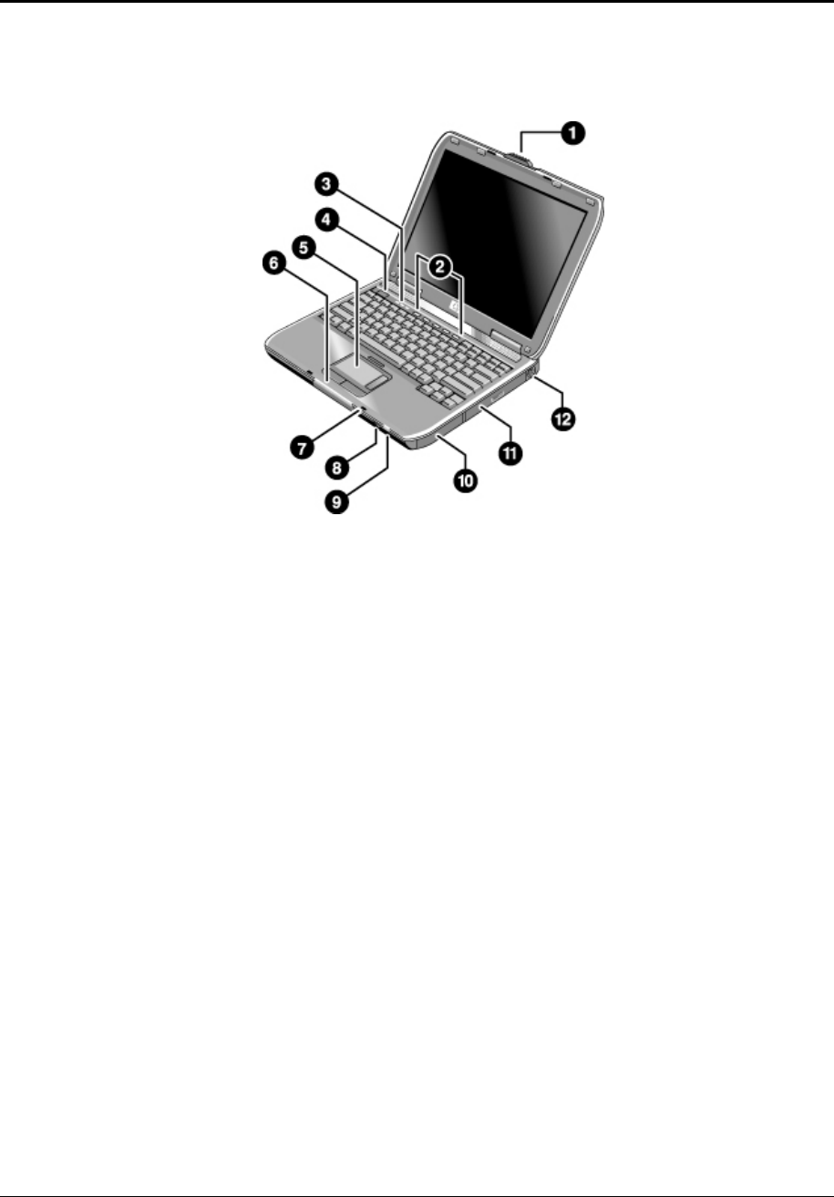
The following illustrations show the notebook’s main external features. For an exploded view of the
notebook, see page 4-2.
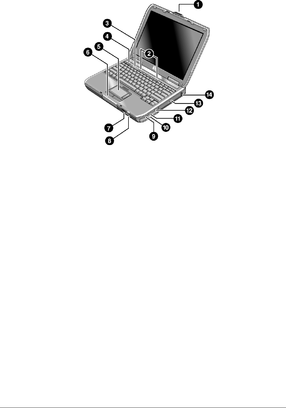
Figure 1-1. Front View
HP Pavilion ze4x00, HP nx9005 and nx9000,
Compaq Evo Notebook N1050v and N1010v,
and Compaq Presario 2100 and 1100
1. Notebook open/close latch
2. One-touch buttons
3. Keyboard status lights
4. Power button: turns the notebook on and off
5. Touch pad, scroll pad, Select buttons, and plus
on-off button
6. Main status lights (left to right): power mode,
hard disk activity, and battery
7. Microphone option (not available)
8. Infrared port (select models only)
9. Wireless on-off button and indicator light
(select models only)
10. Battery
11. CD-ROM, DVD, or other drive
12. PS/2 keyboard or PS/2 mouse port
(supports Y adapter)
Service Manual Product Information 1-9
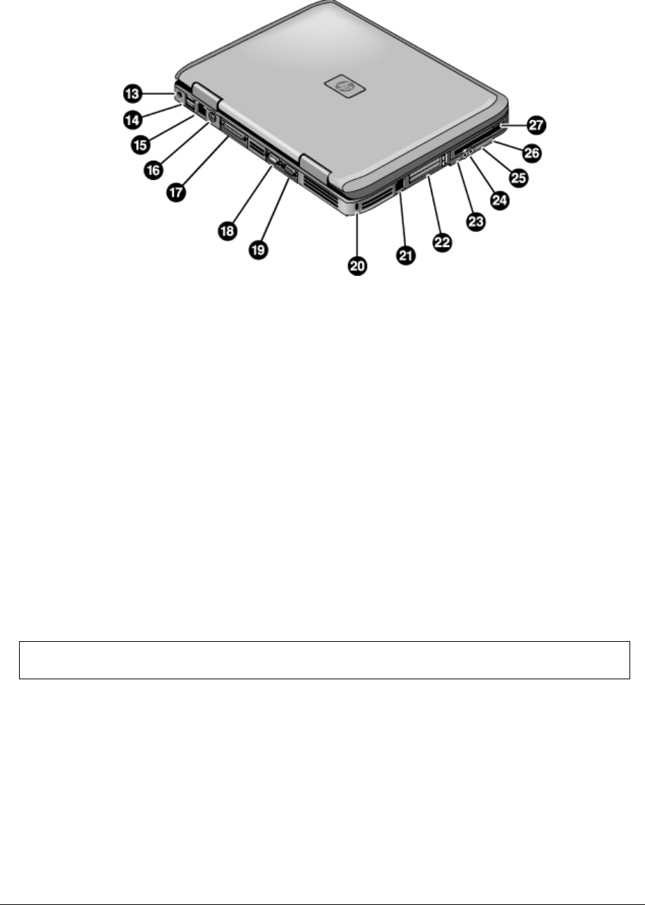
Figure 1-2. Back View
HP Pavilion ze4x00
HP nx9005 and nx9000
13. AC adapter jack
14. Two universal Serial Bus (USB) ports
15. LAN port (select models only)
16. S-Video port (select models only)
17. Parallel port (LPT1): use this port for a parallel
printer or other parallel device
18. Serial port (COM1): use this port for a serial
mouse, modem, printer, or other serial device
19. External monitor port
20. Kensington lock slot (security connector)
21. Modem port (select models only)
22. PCMCIA card and CardBus slot and button
23. IEEE 1394 port (select models only)
24. Audio jacks (left to right): external microphone
and audio out (headphones)
25. Volume controls (select models only)
26. Audio mute button and audio mute light
(select models only)
27. Floppy drive (select models only)
NOTE: Compaq Evo Notebook N1050v, N1010v, and Compaq Presario 2100 and 1100 very similar
except for logo.
1-10 Product Information Service Manual
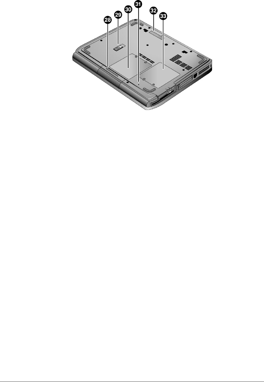
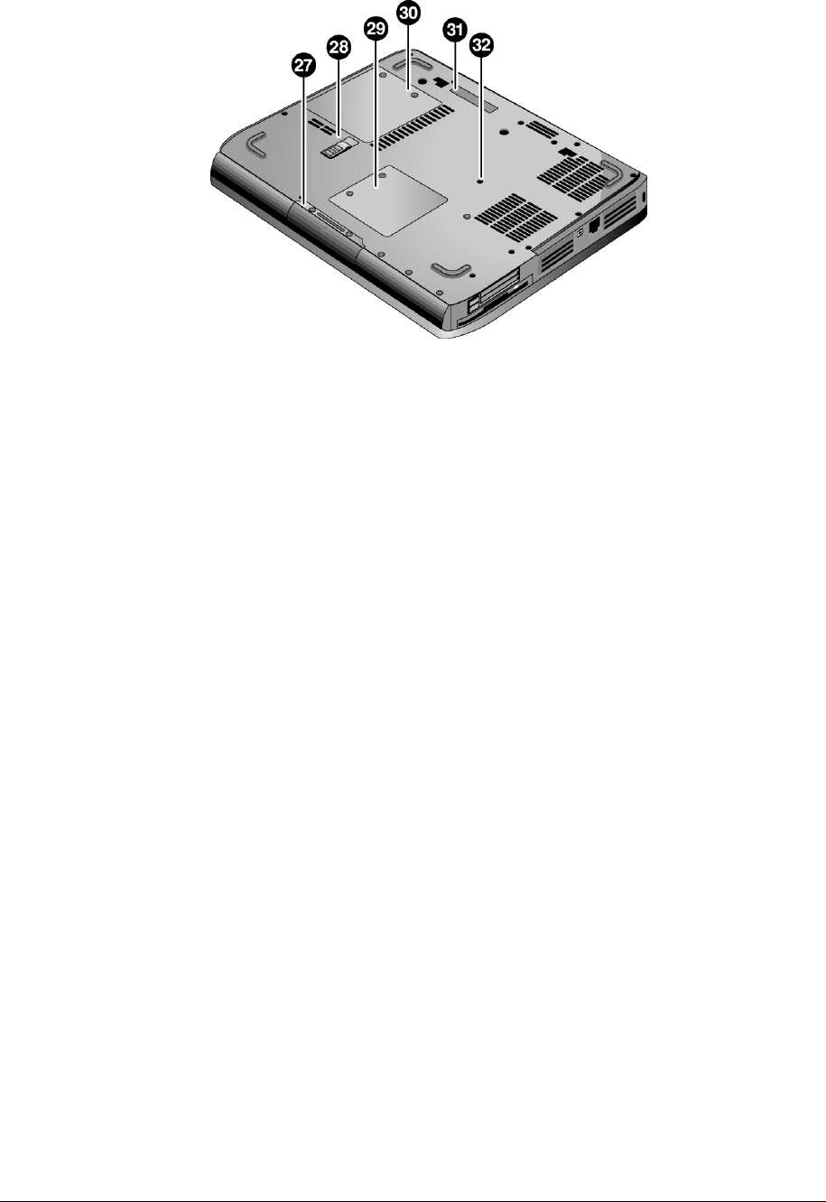
Figure 1-3. Bottom View
HP Pavilion ze4x00, HP nx9005 and nx9000,
Compaq Evo Notebook N1050v and N1010v,
and Compaq Presario 2100 and 1100
28. Hard disk drive
29. Battery latch
30. SDRAM door
31. Reset button
32. Port replicator connect (select models only)
33. Mini PCI door (no user parts inside)
Service Manual Product Information 1-11
Figure 1-4. Front View
HP Pavilion ze5x00,
HP nx9010 and HP nx9008, and
Compaq Presario 2500
1. Notebook open/close latch
2. One-touch buttons
3. Keyboard status lights
4. Power button: turns the notebook on and off
5. Touch pad, scroll pad, Select buttons, and plus
on-off button
6. Main status lights (left to right): power mode,
hard disk activity, and battery
7. Infrared port (select models only)
8. Wireless on-off button and indicator light
(select models only)
9. Audio mute button and audio mute light
(select models only)
10. Battery
11. Volume controls (select models only)
12. Audio jacks (left to right): external microphone
and audio out (headphones)
13. CD-ROM, DVD, or other drive
14. Universal Serial Bus (USB) port
1-12 Product Information Service Manual
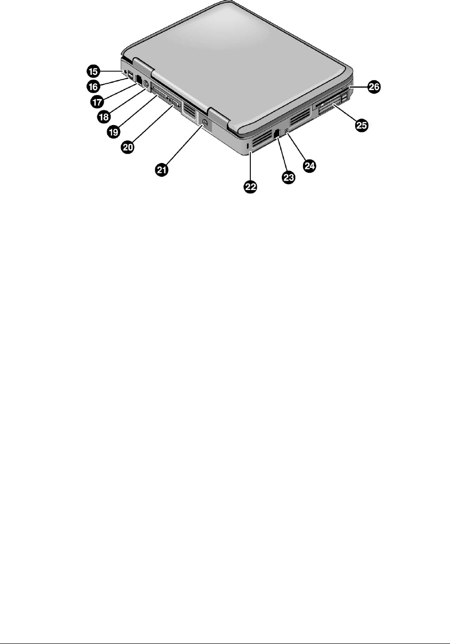
Figure 1-5. Back View
HP Pavilion ze5x00, HP nx9010, and HP nx9008
15. AC adapter jack
16. Two universal Serial Bus (USB) ports
17. LAN port (select models only)
18. External keyboard/mouse port
19. Parallel port (LPT1): use this port for a parallel
printer or other parallel device
20. External monitor port
21. S-Video port (select models only)
22. Kensington lock cable slot (security connector)
23. Modem port (select models only)
24. IEEE 1394 port (select models only)
25. PCMCIA card and CardBus slot and button
26. Floppy drive (select models only)
Service Manual Product Information 1-13
Figure 1-6. Bottom View
HP Pavilion ze5x00, HP nx9010, HP nx9008,
and Compaq Presario 2500
27. Hard disk drive
28. Battery latch
29. Mini PCI door (no user parts inside)
30. SDRAM door
31. Port replicator connect (select models only)
32. Reset button
1-14 Product Information Service Manual
Operation
This section gives an overview of the notebook’s operation.
Turning the Notebook On and Off
You can start and stop your notebook using its power button. However, at certain times you might want to
use other methods to start or stop the notebook—depending on power considerations, types of active
connections, and start-up time.
NOTE: This manual describes the notebook in its original factory configuration, with all settings at their
default values.
Table 1-2. Activating Power Modes
Power mode To enter this mode
On
Power mode status light is on
Press the power button
Standby mode
Saves significant power
Turns off the display and other components
Maintains current session in RAM
Restarts quickly
Restores network connections
Power mode status light blinks
Press the power button
–or–
select Start > Turn Off Computer > Stand By (Windows XP)
–or–
select Start > Shut Down > Standby (Windows 2000)
–or–
allow timeout
Hibernation mode
Saves maximum power
Saves current session to disk, and then shuts down.
Restores network connections
Power mode status light is off
Press Fn+F12
–or–
select Start > Shut Down > Hibernate (Windows 2000)
–or–
allow timeout
Shut down (off)
Saves maximum power
Turns off without saving current session
At startup, resets everything, starts a new session, and
restores network connections.
Power mode status light is off
Select Start > Turn Off Computer > Turn Off (Windows XP)
–or–
Select Start > Shut Down > Shut down (Windows 2000)
–or–
press the power button for 4 seconds (only if the Start menu
procedure doesn’t work)
To turn on: Press the power button to restart, or to resume your session from Standby or Hibernation mode.
Service Manual Product Information 1-15
Checking the Status of the Notebook
The main status lights on the front of the notebook report power status, battery status, and hard disk activity.
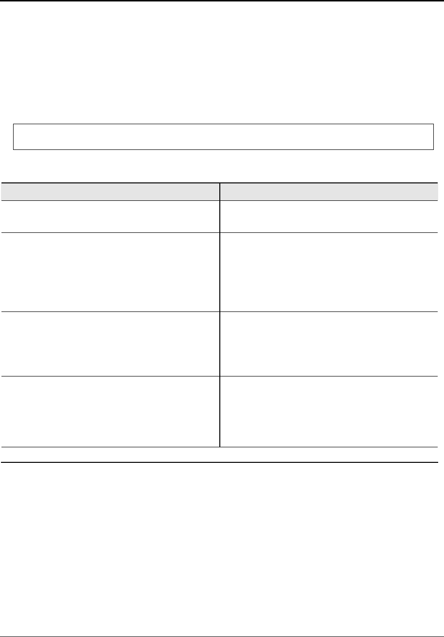
Table 1-3. Main Status Lights (front of notebook)
Meaning
Power status
On: notebook is on (even if the display is off).
Blinking: notebook is in Standby mode.
Off: notebook is off or in Hibernation mode.
Hard disk drive activity
On: notebook is accessing the hard disk drive.
Battery status
Green: The AC adapter is connected and the battery is fully charged.
Amber: The AC adapter is connected and the battery is charging.
Blinking: The AC adapter is connected and the battery is missing or has a fault.
Off: The AC adapter is not connected.
The keyboard status lights, located above the keyboard, indicate the states of the keyboard locks.
Table 1-4. Keyboard Status Lights
Meaning
Caps Lock
Caps Lock is active.
Num Lock
Num Lock is active. (The Keypad Lock must also be on to use the embedded keypad.)
Keypad Lock
The embedded keypad is active (Fn+F8). Num Lock must also be on for the numeric keys;
otherwise, cursor control is active (as marked on an external keyboard).

1-16 Product Information Service Manual
Using Fn Hot Keys
The combination of the Fn key plus another key creates a hot key—a shortcut key sequence—for various
system controls. To use a hot key, press and hold Fn, press the appropriate second key, then release both
keys.
Table 1-5. Fn Hot Keys
Hot Key Effect
Fn+F1 Decreases the display brightness
Fn+F2 Increases the display brightness
Fn+F5 Toggles among the built-in display, an external display, and simultaneous display on both.
Fn+F8 Toggles the built-in keypad on and off. Does not affect an external keyboard. If Num Lock is on, then
the numeric functions are active; otherwise, cursor control is active (as marked on an external
keyboard).
Fn+F12 Enters Hibernation mode
Fn+NumLock Toggles Scroll Lock on and off
Fn+Page Up Increases the audio volume and cancels the mute setting
Fn+Page Down Decreases the audio volume
Fn+Backspace Audio mute
Service Manual Product Information 1-17
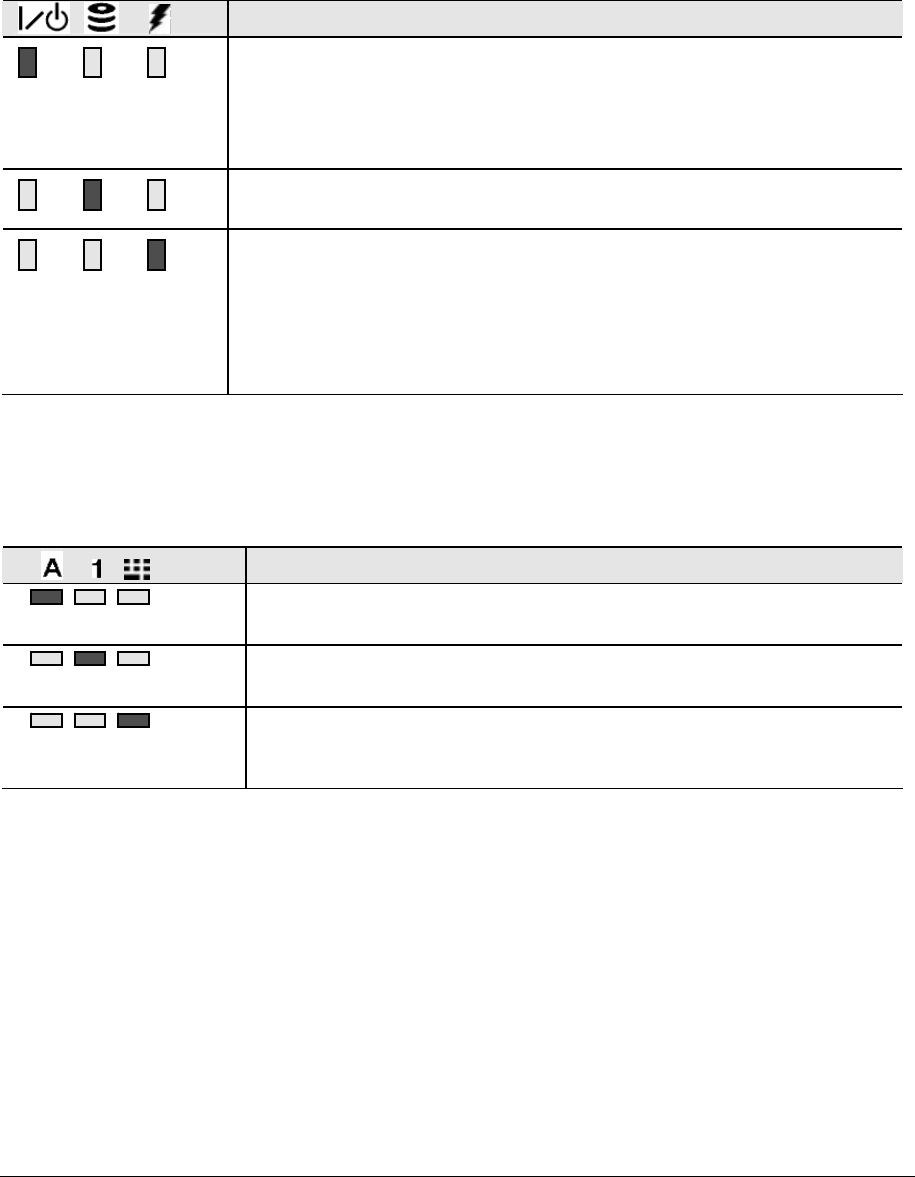
Resetting the Notebook
Occasionally, Windows or the notebook might stop responding, so that you cannot turn the notebook off. If
this happens, try the following in the order listed. Press the power button to restart.
• If possible, shut down Windows:
Press ctrl+alt+del, and then select Shut Down, Restart.
If the system will not allow a software shutdown, press and hold down until the display shuts down
(about 4 seconds) and then release the power button. Press the power button again to restart.
• Use a ballpoint pen or a straightened paper clip to press the reset button on the bottom of the notebook.
Figure 1-7. Resetting the Notebook
NOTE: To boot from a CD, insert a bootable CD (such as the Recovery CDs) into the CD/DVD
drive, and then restart. Press esc when the HP logo appears, and then select the CD/DVD drive as
the temporary boot device.

1-18 Product Information Service Manual
Specifications
The following tables list the specifications for the notebook and its accessories and are subject to change.
For the latest versions, see the HP Notebook Web site http://www.hp.com/notebooks.
Table 1-6. Specifications
Physical Attributes Size (14-inch display): 328 × 272 × 33 mm (12.9 × 10.7 × 1.3 in)
Size (15-inch display): 328 × 272 × 35 mm (12.9 × 10.7 × 1.4 in)
Weight: 2.9 kg (6.5 lb) minimum, depending on configuration
Processor and Bus
Architecture
HP Pavilion ze5600:
2.4-, 2.66-, 2.8-, or 3.06-GHz Mobile Intel Pentium 4 ProcessorM with
Intel Speed Step technology, 512-KB L2 cache, and 1.2- to 1.3-V core low-power
processor with 400-MHz processor system bus
-or-
2.6- or 2.8-GHz Intel Celeron processor with 128-KB L2 cache and 1.45-V core low-power
processor with 400-MHz processor system bus
HP Pavilion ze5500:
2.4-, 2.66-, 2.8-, or 3.06-GHz Mobile Intel Pentium 4 processor with
Intel Speed Step technology, 512-KB L2 cache, and 1.2- to 1.3-V core low-power
processor with 400-MHz processor system bus
-or-
2.6-GHz Mobile Intel Celeron processor with 128-KB L2 cache and 1.45-V core low-power
processor with 400-MHz processor system bus
HP Pavilion ze5400 or ze5300:
2.4-, 2.53-, 2.66-, or 2.8-GHz Intel Pentium 4 processor-D or 2.4-, 2.53-, 2.66-,
or 2.8-GHz Mobile Intel Pentium 4 with Intel Speed Step technology, 512-KB L2 cache,
processor with 400-MHz processor system bus
HP Pavilion ze5200:
2.4-, 2.53-, 2.66-, or 2.8-GHz Intel Desktop Pentium 4 processor-D with
Intel Speed Step technology, 512-KB L2 cache, and 1.2- to 1.3-V core low-power
processor with 400-MHz processor system bus
HP Pavilion ze4600 or ze4500:
1.87-GHz AMD Athlon XP-M with Intel Speed Step technology, 512-KB L2 cache, and 1.2-
to 1.3-V core low-power processor with 200- or 266-MHz (double-clocked) processor
system bus
HP Pavilion ze4400:
1.8- or 1.87-GHz AMD Athlon XP-M with Intel Speed Step technology,
512-KB L2 cache, and 1.2- to 1.3-V core low-power processor with 200- or 266-MHz
(double-clocked) processor system bus

Service Manual Product Information 1-19
Processor and Bus
Architecture
(continued)
HP Pavilion ze4300:
1.8-, 2.0-, 2.2-, or 2.4-GHz Mobile Intel Pentium 4 processor-M with Intel Speed Step
technology, 512-KB L2 cache, and 1.2- to 1.3-V core low-power processor with
400-MHz processor system bus
-or-
1.8-, 2.0-, or 2.2-GHz Mobile Intel Celeron processor with 256-KB L2 cache and
1.45-V core low-power processor with 133-MHz processor system bus
-or-
1.46-, 1.53-, 1.67-, 1.80-, or 2.0-GHz Athlon processor with 256-KB L2 cache and
1.45-V core low-power processor with 133-MHz processor system bus
HP Pavilion ze4200:
1.8-, 1.9-, 2.0-, or 2.2-GHz Mobile Intel Pentium 4 processor-M with Intel Speed Step
technology, 512-KB L2 cache, and 1.2- to 1.3-V core low-power processor with
400-MHz processor system bus
-or-
1.6-, 1.7-, 1.8-, or 2.0-GHz Mobile Intel Celeron processor with 256-KB L2 cache and
1.45-V core low-power processor with 133-MHz processor system bus
-or-
1.46-, 1.53-, 1.67-, or 1.80-GHz AMD Athlon processor with 256-KB L2 cache and
1.45-V core low-power processor with 133-MHz processor system bus
HP Pavilion ze4100:
1.7-, 1.8-, or 2.0-GHz Mobile Intel Pentium 4 processor-M with Intel Speed Step
technology, 512-KB L2 cache, and 1.2- to 1.3-V core low-power processor with
400-MHz processor system bus
-or-
1.6-, 1.7-, or 1.8-GHz Mobile Intel Celeron processor with 256-KB L2 cache and
1.45-V core low-power processor with 133-MHz processor system bus
HP nx9010:
2.4-, 2.53-, or 2.66-GHz Intel Desktop Pentium 4 processor-D with
Intel Speed Step technology, 512-KB L2 cache, and 1.2- to 1.3-V core low-power
processor with 400-MHz processor system bus
-or-
2.0-GHz Mobile Intel Celeron-D processor with 256-KB L2 cache and
1.45-V core low-power processor with 133-MHz processor system bus
HP nx9008:
2.6- and 2.8-GHz Mobile Intel Celeron-D processor with 256-KB L2 cache and
1.45-V core low-power processor with 133-MHz processor system bus
HP nx9000:
1.8- or 2.0-GHz AMD Athlon processor with 256-KB L2 cache and 1.45-V core low-power
processor with 133-MHz processor system bus
Compaq Evo Notebook N1050v:
1.8-GHz Mobile Intel Pentium 4 Processor-M with Intel Speed Step technology,
512-KBL2 cache, and 1.2- to 1.3-V core low-power processor with 400-MHz processor
system bus
-or-
1.6-GHz Intel Celeron processor with 256-KB L2 cache and 1.45-V core low-power
processor with 133-MHz processor system bus
Compaq Evo Notebook N1010v:
1.6-GHz Intel Celeron processor with 256-KB L2 cache and 1.45-V core low-power
processor with 133-MHz processor system bus

1-20 Product Information Service Manual
Processor and Bus
Architecture
(continued)
Compaq Presario 2500:
1.8-, 2.0-, 2.4-, 2.53-, 2.66-, or 2.80-GHz Intel Desktop Pentium 4 processor-D with
Intel Speed Step technology, 512-KB L2 cache, and 1.2- to 1.3-V core low-power
processor with 400-MHz processor system bus
Compaq Presario 2100:
1.8-, 1.9-, 2.0-, or 2.2-GHz Mobile Intel Pentium 4 Processor-M with Intel Speed Step
technology, 512-KB L2 cache, and 1.2- to 1.3-V core low-power processor with
400-MHz processor system bus
-or-
2.53-GHz Intel Desktop Pentium 4 processor-D with Intel Speed Step technology,
512-KB L2 cache, and 1.2- to 1.3-V core low-power processor with 400-MHz processor
system bus
-or-
1.6-, 1.7-, 1.8-, or 2.0-GHz Intel Celeron processor with 256-KB L2 cache and
1.45-V core low-power processor with 133-MHz processor system bus
-or-
1.46-, 1.53-, 1.67-, or 1.80-GHz AMD Athlon processor with 256-KB L2 cache and
1.45-V core low-power processor with 133-MHz processor system bus
Compaq Presario 1100:
1.6- or 1.8-GHz Intel Celeron processor with 256-KB L2 cache and 1.45-V core low-power
processor with 133-MHz processor system bus
Video 14.1-inch XGA (1024 × 768), or 15.0-inch XGA (1024 × 768) or SXGA+ (1400 × 1050)
active-matrix (TFT) LCD display
Hardware 3D acceleration, hardware DVD acceleration
External monitors up to 1600 × 1200 resolution, 16M colors, and at least 85 Hz refresh rate
(only 60 Hz at 1400 × 1050). Refresh rate and clarity may vary depending on monitor,
resolution, and color depth
ATI Mobility Radeon graphics accelerator with 16-, 32-, or 64-MB DDR graphics memory,
4x AGP graphics capability
Dual display capability (depends on operating system support)
Power Rechargeable lithium-ion (14.8 Vdc) or nickel-metal-hydride (9.6 Vdc) battery with LED
charge-level gauge
Battery life: up to 3 (Li ion) or 2 (NiMH) hours typical (varies with model, usage, and power
settings)
Fast battery recharge: 2 hours when system is off, 3 hours when system is on.
Low-battery warning
Suspend/resume capability
Universal AC adapter: 100–240 Vac (50/60 Hz) input, 19 Vdc output, or 75 W
Mass Storage 20- to 60-GB removable hard drive with Ultra-DMA 100 interface
1.44-MB floppy drive (certain models)
24x CD-ROM, 8x DVD, CD-RW, or CD-RW/DVD drive (or higher)
RAM At least 128 MB SDRAM preinstalled
HP Pavilion ze5x00, ze4x00, Compaq Evo N1050v, Compaq Presario 2500, and Compaq
Presario 2100:
2 slots for PC2100 DDR-266 SDRAM modules
Up to 1 GB (1024 MB) SDRAM using 512 MB modules
Compaq Evo N1010v and Presario 1100:
2 slots for PC2100 DDR-266 SDRAM modules
Up to 512 MB SDRAM using 256 MB modules

Service Manual Product Information 1-21
Audio System Stereo sound via 2 built-in speakers
3D-enhanced audio
Volume and mute buttons (certain models)
Headphone-out and microphone-in
Keyboard and
Pointing Device
87/88-key touch-type QWERTY keyboard with 101/102 key emulation. Embedded
numeric keypad.
12 function (Fn) keys
5 user-programmable One-Touch buttons
Touch pad with integrated scroll pad, on-off button and indicator
Left and right Select buttons
LAN
(select models only)
Ethernet 10Base-T (10 Mbps) and 100Base-TX (100 Mbps) support
Supports wake-on-LAN, fast IP, DMI, dRMON
MBA (Managed Boot Agent) support for PXE/BINL, NCP/IPX, DHCP
Wireless LAN
(select models only)
802.11b or 802.11g (54g)
1-22 Product Information Service Manual
Table 1-7. Accessories
Accessory Description
HP Pavilion
ze5x00
HP nx9010
and
nx9008
Compaq
Presario
2500
HP Pavilion
ze4x00
HP nx9005
Compaq
Evo N10
50v
HP Pavilion
ze4600
ze4500
ze4400
ze4200
HP nx9000
Compaq
Presario
2100
Compaq
Evo
N1010v
Compaq
Presario
1100
HP Pavilion
ze4100
Memory
F4694-60901
317434-001
128MB DDR266B
• • • •
F4695-60901
317435-001
256MB DDR266B
• • • •
F4696-60901
317436-001
512MB DDR266B
• • •
Hard Drives
0950-4193
319412-001
HDD-20 GB 9.5mm,
Hitachi ATA100
• • • • •
0950-4318 HDD-20 GB 9.5mm,
IBM ATA100 FDB
• •
0950-4287 HDD-20 GB 9.5mm,
TOSH ATA100 FDB
• •
0950-4168 HDD-30 GB 9.5mm,
Hitachi ATA100
• •
0950-4162
319413-001
HDD-30 GB 9.5mm,
IBM (diablo) ATA100
• • • • •
0950-4319 HDD-30 GB 9.5mm,
IBM ATA100 FDB
(Cascade)
• •
0950-4360 HDD-30 GB 9.5mm,
TITAN Toshiba
ATA100 (TITAN)
• •
0950-4176 HDD-30 GB 9.5mm,
Toshiba ATA100
• •
0950-4320
319414-001
HDD-40 GB 9.5mm,
IBM ATA100 FDB
• • • •
0950-4288 HDD-40 GB 9.5mm,
Toshiba ATA100
•
319415-001 SPS-DRV HD 60 GB
(4200 rpm)
• • •
319416-001 SPS-DRV HD 60 GB
(5400 rpm)
• •
320692-001 SPS-DRV HD 80 GB
(4200 rpm)
• •
Power Options
F4600-60901 AC-Adapter-Ultraslim
Delta 75W s/PFC
• •
F4809-60901 Battery, Li ion 4.4AHr • • • • •
Service Manual Product Information 1-23
Accessory Description
HP Pavilion
ze5x00
HP nx9010
and
nx9008
Compaq
Presario
2500
HP Pavilion
ze4x00
HP nx9005
Compaq
Evo N10
50v
HP Pavilion
ze4600
ze4500
ze4400
ze4200
HP nx9000
Compaq
Presario
2100
Compaq
Evo
N1010v
Compaq
Presario
1100
HP Pavilion
ze4100
319411-001 8 Cell Li ion
8120-6312
317444-011
Cord, Pwr, Austr
ABG (2w)
• • •
8120-6314 Cord, Pwr, Europe
ABB (2w)
• •
317444-002 SPS-CORD-AC PWR
2 WIRE-INTL
•
317444-061 SPS-CORD-AC PWR
2 WIRE-IT
•
8120-6316
317444-291
Cord, Pwr, Japan
ABJ (2w)
• •
317444-AD1 SPS-CORD-AC PWR 2
WIRE-KOR
•
8120-8373
317444-AA1
Cord, Pwr, People’s
Republic of China
AB2 (2w)
•
317444-101 SPS-CORD-AC PWR
2 WIRE-SWE
•
317444-111 SPS-CORD-AC PWR
2 WIRE-SWI
•
317444-AB1 SPS-CORD-AC PWR
2 WIRE-TAI
•
8120-8699
317444-031
Cord, Pwr, UK (EPSR) for
Hong Kong (2w)
• • •
8120-6313
317444-001
Cord, Pwr, US ABA (2w) • • •
PC Cards
F4640-60978
319468-051
Card, Mini PCI-802.11B
France
• • • •
F4640-60977
319468-002
Card, Mini PCI-802.11B
worldwide
• • • • •
Docking
F4808-60901 Port Replicator Assy • • •
F4808-60902 Simple Port Replicator
hp/Compaq
• •
1-24 Product Information Service Manual
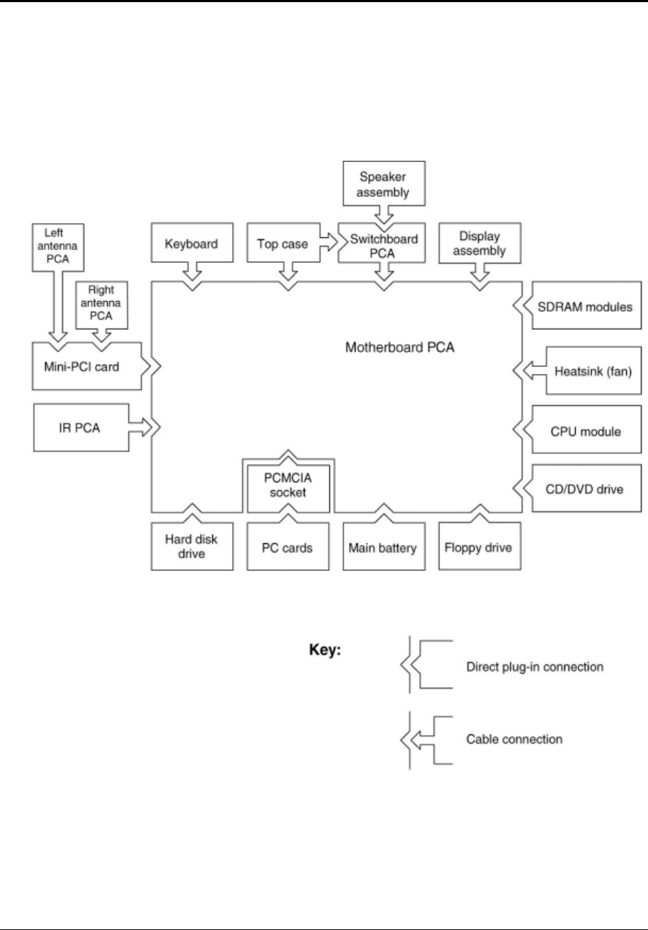
Internal Design
The motherboard PCA is the central component of the notebook’s design. It plays a role in virtually
all system functions. The CPU module and most other subsystems connect to the motherboard.
The following figure shows the connections among the notebook’s replaceable electronic modules.
Table 1-8 on page 1-25 lists the roles that these modules play in the notebook’s functional subsystems.
Figure 1-8. Replaceable Module Diagram

Service Manual Product Information 1-25
Table 1-8. Functional Structure Description
Bootup CPU module
Motherboard
Hard disk drive
Floppy drive
Main processor (MMO)
Primary system circuitry, system BIOS
First source of disk-based startup code
Second source of disk-based startup cod.
Processor CPU module
Motherboard
Main processor, numeric data processor, L1 and L2 cache
Primary system circuitry
Memory Motherboard
SDRAM module
Video RAM (XE4500)
Changeable SDRAM (2 slots), video RAM (XE4100)
Power Battery
Motherboard
Switchboard PCA
AC adapter
Power storage
AC adapter socket, reset button, lid switch, power supply, power control circuitry
Power button
AC-to-DC converter
Display Motherboard
SDRAM module
Display assembly
Graphics controller, video RAM
Display output, backlight, power converter for backlight
Hard disk Motherboard
Hard disk drive
Hard disk controller
Hard disk mechanism
Floppy drive Motherboard
Floppy drive
I/O controller, floppy connector
Floppy drive mechanism
Keyboard Motherboard
Switchboard PCA
Keyboard
Keyboard BIOS, keyboard controller
Power switch, one-touch buttons
Key switches
PS/2
TouchPad
Motherboard
Top case
Keyboard circuitry, keyboard controller, keyboard BIOS
Touch pad sensor, Select buttons, controller (PS/2 output)
Audio Motherboard
Speaker assembly
Audio controller, audio decoder, speaker amplifier, microphone, external audio
jacks, headphone amplifier, audio-off switch
Speakers
Status Motherboard
Switchboard PCA
Top case
LED circuitry, keyboard controller
Keyboard LEDs
Main status LEDs
Serial Motherboard I/O controller, serial connector
Parallel Motherboard I/O controller, parallel connector
Infrared Motherboard
IR PCA
I/O controller
Infrared transmitter/receiver
PS/2 port Motherboard PS/2 connector, keyboard controller
USB Motherboard Bus controller (South Bridge), USB connector
S-Video Motherboard I/O controller, S-video connector (certain models)

1-26 Product Information Service Manual
Port Replicator Motherboard Port replicator logic, port replicator connector (certain models)
PCMCIA Motherboard
PCMCIA socket
PCMCIA controller
PCMCIA connector
Wireless LAN
(select
models only)
Mini PCI
Antenna PCAs
IR PCA
I/O controller, radio, radio frequency circuitry
Transmit/receive antennas
On/off switch, indicator light
LAN Motherboard LAN circuitry, bus controller, LAN connector
Modem Motherboard Modem circuitry (select models), modem connector
Service Manual Removal and Replacement 2-1
2
Removal and Replacement
This chapter tells you how to remove and replace the notebook’s components and assemblies. The items
marked by • in the following table are user-replaceable.
Table 2-1. Removal Cross-Reference
Assembly, display (page 2-23)
• Assembly, speaker (page 2-15)
• Battery, main (page 2-4)
• Card, wireless LAN Mini PCI (page 2-7)
Case, bottom (page 2-59)
Case, top (page 2-26)
CPU module (page 2-44)
• Cover, keyboard (page 2-16)
• Door, Mini PCI (page 2-7)
• Door, SDRAM (page 2-5)
Doors, PCMCIA (page 2-60)
Drive, CD/DVD (page 2-20)
Drive, floppy (page 2-32)
• Drive, hard disk (page 2-9)
• Feet, rubber (page 2-12)
Heat sink (with fan) (page 2-40)
• Keyboard (page 2-16)
• Module, CPU (page 2-44)
Module, RJ11/1394 (page 2-48)
Module, SDRAM (page 2-5)
PCA, antennas (page 2-60)
PCA, audio (page 2-38)
PCA, I/R (page 2-36)
PCA, motherboard (page 2-50)
PCA, switchboard (page 2-19)
• Rubber screw plugs, display (page 2-12)
CAUTION: Always provide proper grounding when performing repairs. Without
proper grounding, an electrostatic discharge can damage the notebook and its
components.
NOTE: Reassembly steps are the reverse of the removal steps. Reassembly notes are included at the
end of each section below.
Symbols like these are displayed throughout this chapter to show approximate full-size
screw outlines. You can use these to verify the sizes of screws before you install them. Installing
a wrong-size screw can damage the notebook. (The symbol at the left represents an M2.5×4.0mm
T-head screw.)
2-2 Removal and Replacement Service Manual
Table 2-2. Required Equipment
• 0 and 1 Phillips screwdrivers, preferably magnetized
• Small flat-blade screwdriver
• 5mm nut driver
Table 2-3. Recommended Screw Torque Values
Screw Thread Size Torque (cm-kgf) Torque (in-lbf)
M2 2,0–2,5 1.7–2.2
M2.5 (hinges) 3,5–4,0 3.0–3.4
M2.5 (other) 2,5–3,0 2.2–2.6
M3 2,5–3,0 2.2–2.6
Standoff, hex 2,5–3,0 2.2–2.6
Service Manual Removal and Replacement 2-3
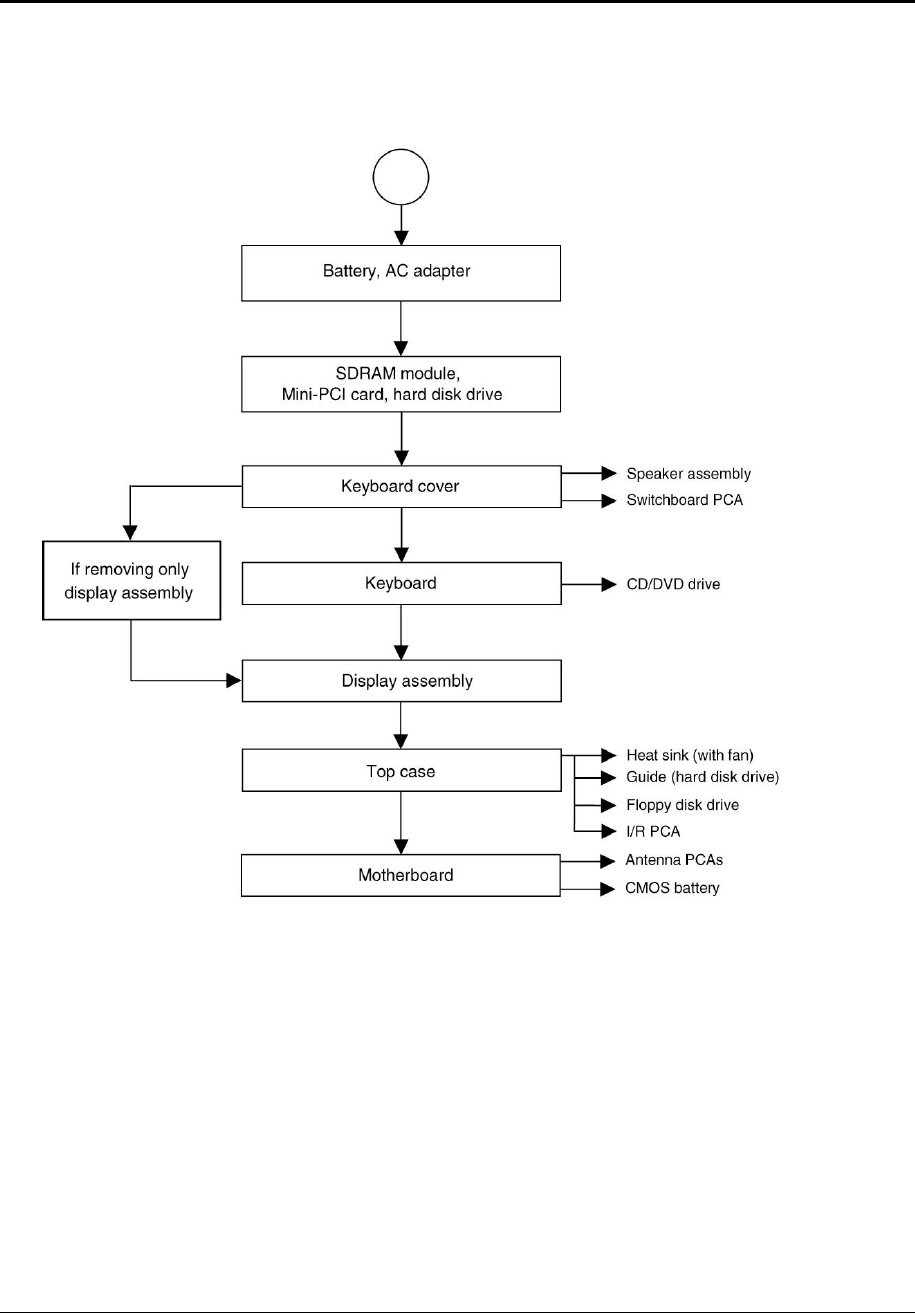
Disassembly Flowchart
The following diagram shows the general “path” you will use when disassembling the notebook to
access any particular component.
Figure 2-1. Disassembly Flow
2-4 Removal and Replacement Service Manual
Removing the Battery
(User-Replaceable)
Required Equipment
None
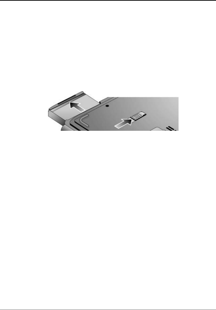
Removal Procedure
Slide the battery’s release latch, and then pull the battery out of its compartment.
Figure 2-2. Removing the Battery
Service Manual Removal and Replacement 2-5
Removing an SDRAM Module
(User-Replaceable)
The notebook has no system memory built into its motherboard, but has 2 slots for SDRAM modules. One
slot contains an SDRAM module that was factory installed.
NOTE: HP Pavilion ze5300, ze5200, ze4300, ze4200, and ze4100, HP nx9010, nx9005 and nx9000,
Compaq Evo Notebook N1050v and N1010v, and Compaq Presario 2500, 2100, and 1100 notebooks use
only DDR266 SDRAM modules. Using the wrong type of module prevents the notebook from booting.
CAUTION: Handle the SDRAM module only by its edges and provide proper grounding, or
you might damage the module through electrostatic discharge.
Required Equipment
1 Phillips screwdriver
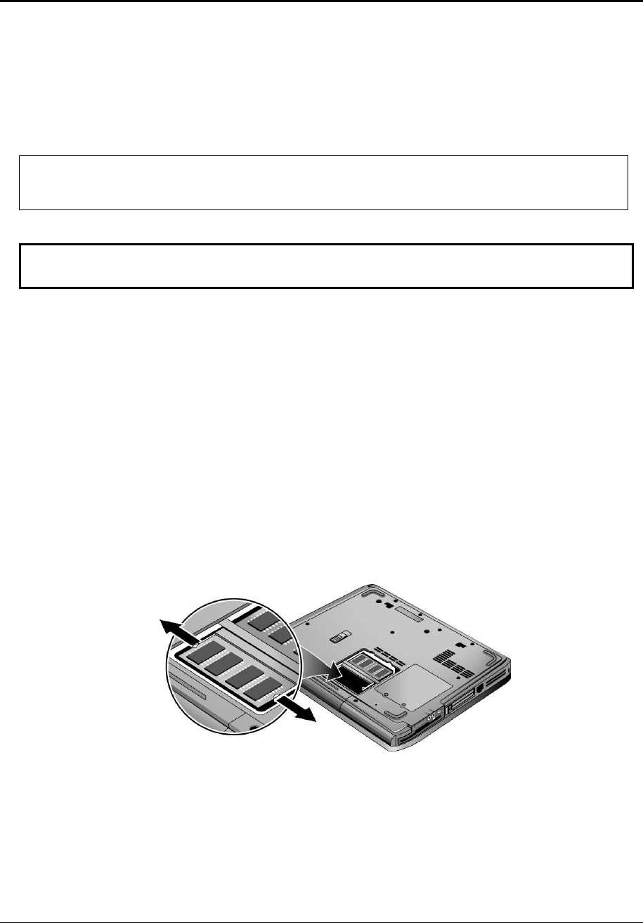
Removal Procedure
1. Unplug the AC adapter, if present, and then remove the battery.
2. On the bottom of the notebook, loosen the captive screws holding the SDRAM door, and then remove
the door.
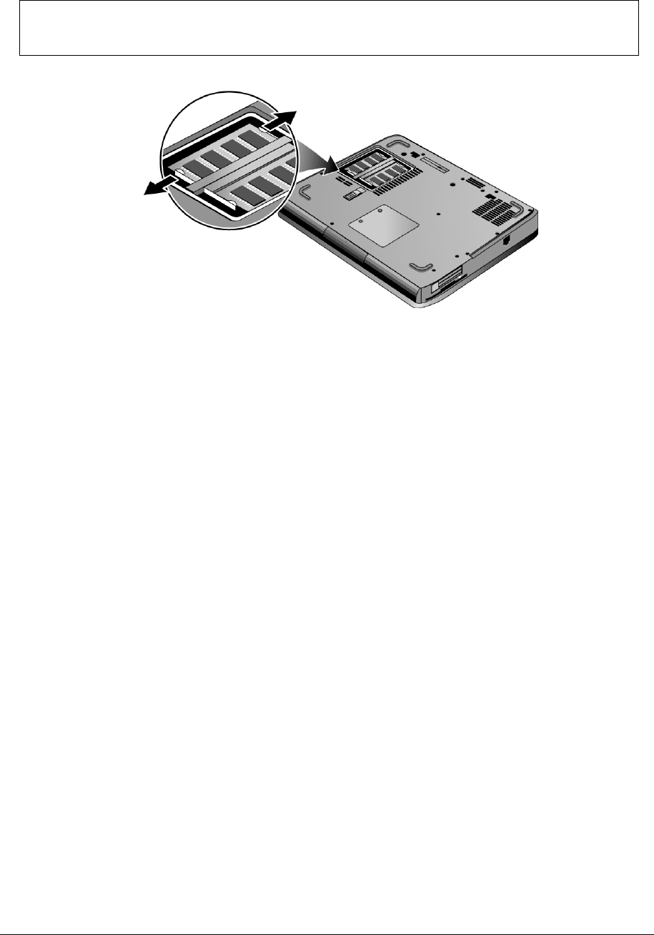
3. Press outward on the latches at the sides of the SDRAM module to release it (the SDRAM module
pops up).
4. Carefully pull the SDRAM module out of the connector.
Figure 2-3. Removing an SDRAM Module
HP Pavilion 4x00, HP nx9005 and nx9000,
Compaq Evo Notebook N1050v and N1010v, and
Compaq Presario 2100 and 1100 Models
2-6 Removal and Replacement Service Manual
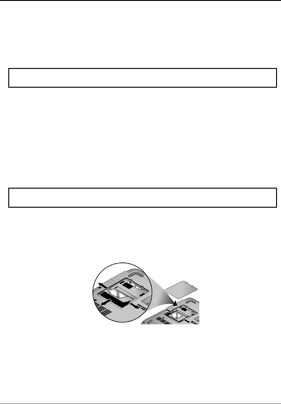
NOTE: The SDRAM door on HP Pavilion ze5x00, HP nx9010 and nx9008, and Compaq Presario 2500
models is located in the rear left corner of the notebook bottom, as indicated in Figure 2-4. The procedure
for removing the SDRAM door and modules is the same for all notebook models.
Figure 2-4. Removing an SDRAM Module
HP Pavilion ze5x00, HP nx9010, nx9008, and
Compaq Presario 2500 Models
Reassembly Notes
Carefully press the SDRAM module into the connector at an angle of about 30°, until it is fully
inserted, and then press down on both sides of the SDRAM module until the latches snap closed.
Service Manual Removal and Replacement 2-7
Removing the Wireless LAN Mini PCI Card
(User-Replaceable)
Certain notebooks include a wireless LAN Mini PCI card under the Mini PCI door on the bottom of
the notebook.
CAUTION: Handle the Mini PCI card only by its edges and provide proper grounding, or you
might damage the card through electrostatic discharge.
Required Equipment
0 Phillips screwdriver
Removal Procedure
1. Unplug the AC adapter, if present, and then remove the battery.
2. On the bottom of the notebook, loosen the captive screws holding the Mini PCI door, and then remove
the door.
CAUTION: Be careful when connecting and disconnecting the antenna cables from the Mini PCI
card. Damaged cables or connectors can degrade notebook performance.
3. Disconnect the 2 antenna cables from the Mini PCI card.
4. Press outward on the latches at the sides of the Mini PCI card to release it (the Mini PCI card pops up).
5. Carefully pull the Mini PCI card out of the connector.
Figure 2-5. Removing the Mini PCI Card
HP Pavilion ze4x00, HP nx9005 and nx9000,
Compaq Evo Notebook N1050v and N1010v, and
Compaq Presario 2100 and 1100 Models
2-8 Removal and Replacement Service Manual
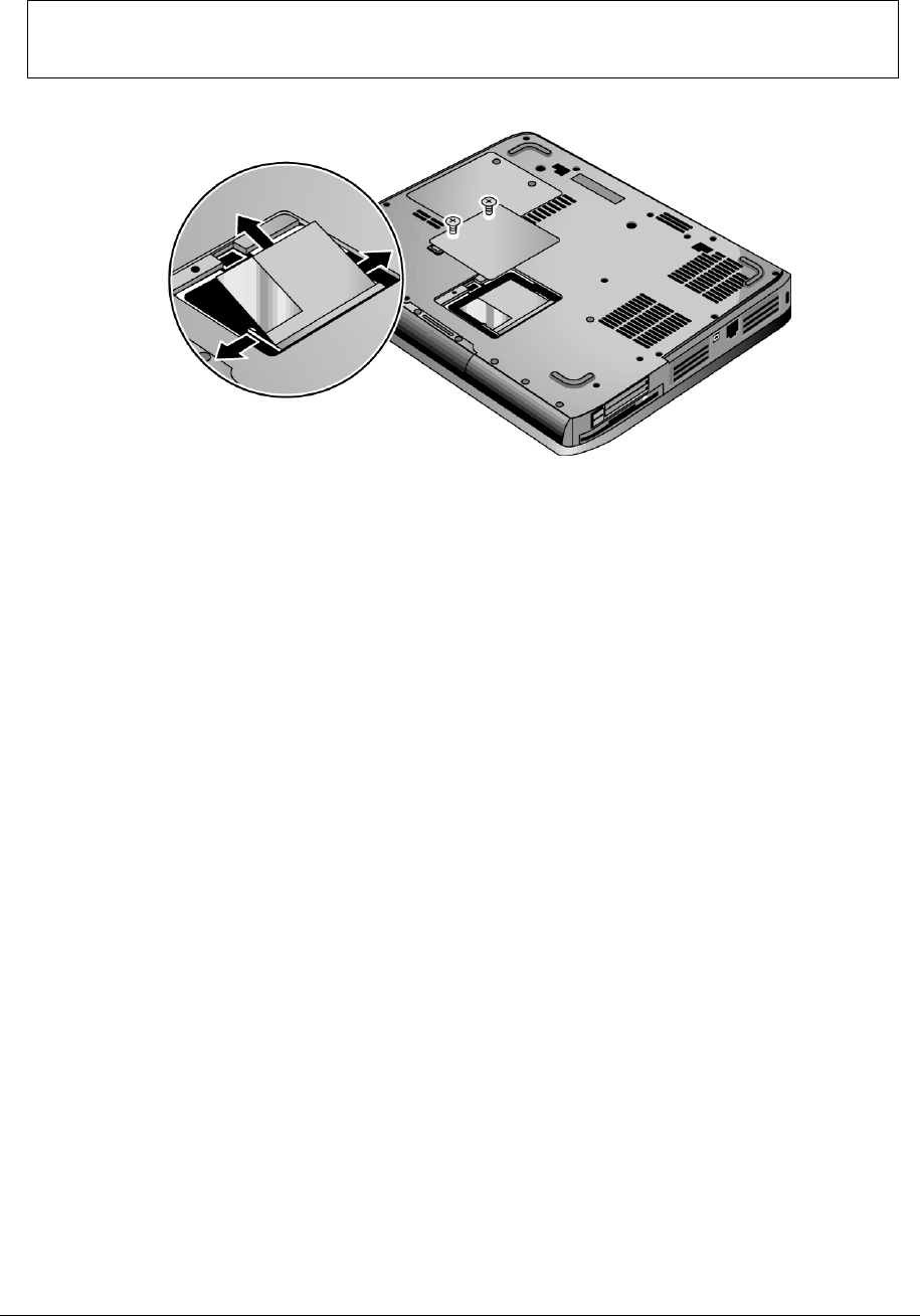
NOTE: The Mini PCI Card door on HP Pavilion ze5x00, HP nx9010 and HP nx9008, and
Compaq Presario 2500 models is located in the front center area of the notebook bottom, as indicated in
Figure 2-6. The procedure for removing the Mini PCI door and card is the same for all notebook models.
Figure 2-6. Removing the Mini PCI Card
HP Pavilion ze5x00, HP nx9010 and nx9008, and
Compaq Presario 2500 Models
Reassembly Notes
Carefully press the Mini PCI card into the connector at an angle of about 30°, until it is fully
inserted, and then press down on both sides of the Mini PCI card until the latches snap closed.
Service Manual Removal and Replacement 2-9
Removing the Hard Disk Drive
(User-Replaceable)
Required Equipment
1 Phillips screwdriver
Removal Procedure
NOTE: If you are installing a new hard disk drive, load the factory software and operating system on the
drive as described in “Recovering the Factory Software”, as shown on the next page.
1. Unplug the AC adapter, if present, and then remove the battery.
2. On the bottom of the notebook, remove the hard disk drive rubber screw plugs and
M2.5×6.0mm screws. (The number of plugs and screws varies by model.)
3. Carefully pull the hard disk drive out of the notebook.
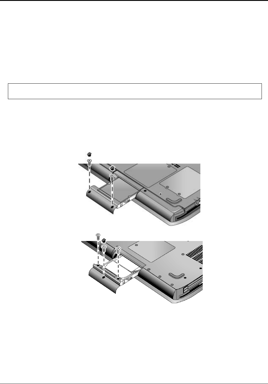
Figure 2-7. Removing the Hard Disk Drive
2-10 Removal and Replacement Service Manual
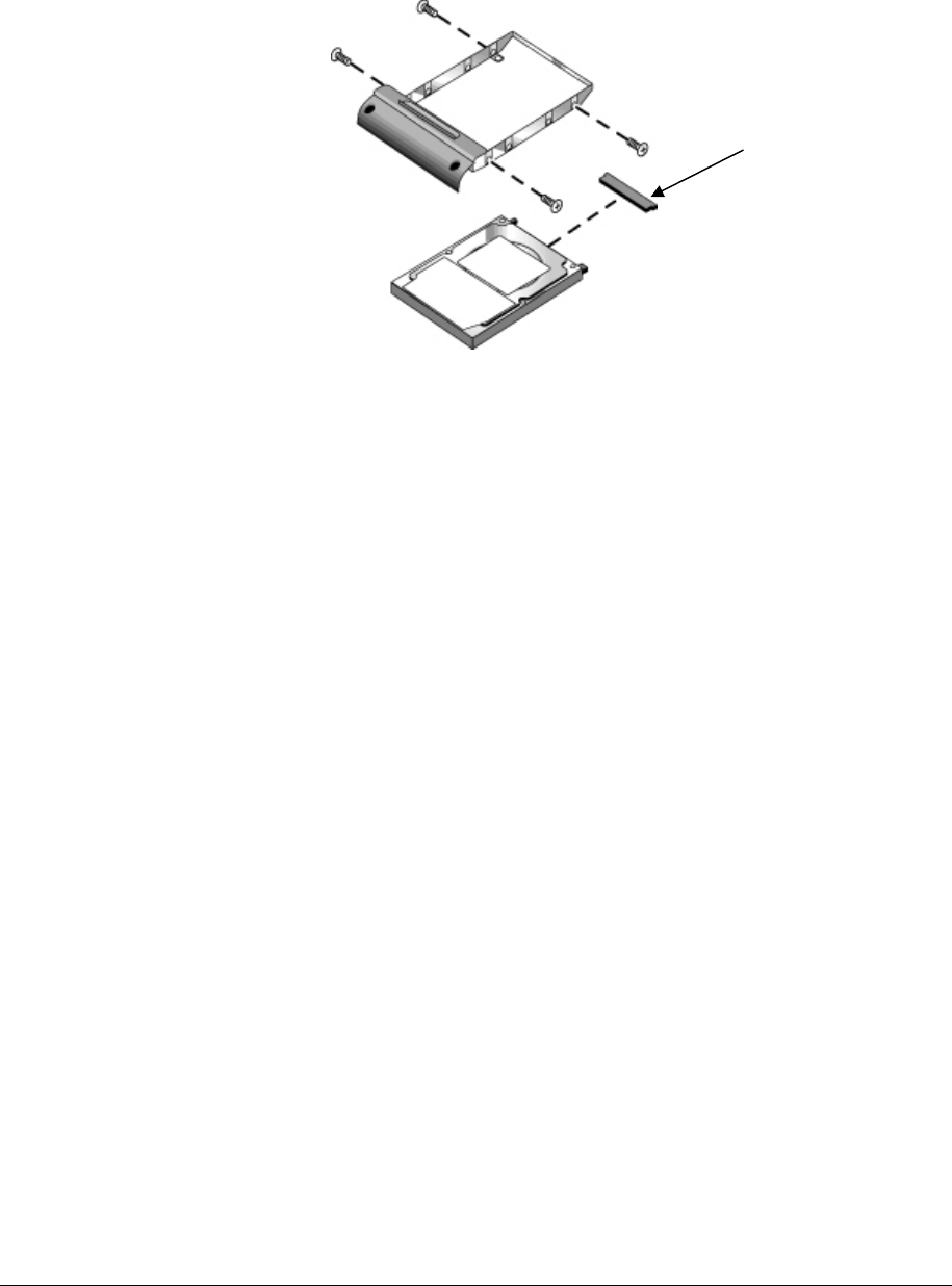
4. Remove the four M3.0×4.0mm screws from the hard disk drive and hard disk drive tray, and
then lift the drive out of the tray.
5. Remove the connector bar from the hard disk drive.
NOTE: Connector bar not used on HP Pavilion ze5x00 series
Figure 2-8. Removing the Hard Disk Drive Tray
See note below

Service Manual Removal and Replacement 2-11
Recovering the Factory Software
The following procedure describes how to recover the notebook’s original operating system and
drivers. This process can take up to 15 minutes to complete. (For more information about recovering
the factory software installation, see the readme.txt file in the root directory of the Recovery CDs.)
CAUTION: Do not interrupt the following process or unplug the AC adapter until the process
completes.
1. Connect the AC adapter to the notebook.
2. Insert the Restore CD (or the Operating System) disk 1 into the notebook’s CD/DVD drive. If the
notebook is turned off, use a pin or straightened paper clip to press the release switch on the drive door
to open it.
3. Turn on or restart the notebook.
4. When the HP logo appears, press esc to display the Boot menu.
5. Use the arrow keys to select the CD/DVD drive as the first boot device, and then press enter.
6. When the dialog box appears, follow the displayed instructions. If prompted, accept the recommended
partition size.
To create the Utility partition without installing the factory software, select Advanced, and then select
not to install the operating system.
If the hard disk is partitioned into several logical drives, you can install the factory software on drive C
without affecting other drives. select Advanced and then select to restore only the C partition.
7. When prompted to reboot the notebook, press ctrl+alt+del, and then follow any instructions that appear.
8. When the operating system has been installed and while Windows is running, replace the OS CD with
the Driver Recovery CD. If autorun is not enabled, select Start > Run. Then type
D:\SWSETUP\APPINSTL\SETUP.EXE (assuming “D:” is your drive designation), and then hit enter.
9. Follow the on-screen instructions for installing the drivers.
10. After the drivers have been installed, the application software may be installed.

2-12 Removal and Replacement Service Manual
Replacing Small Parts
The user can replace the following small parts.
Table 2-4. Replacing Small Parts
Part Replacement Procedure
Rubber screw plugs, display
(on display bezel)
Insert a small flat-blade screwdriver under the rubber screw plug and pry it loose. To replace,
firmly press the adhesive side of the screw plug into the recess.
Door, Mini PCI On the bottom of the notebook, loosen the screws that secure the Mini PCI door to the
bottom case, and then remove the door.
Door, memory On the bottom of the notebook, loosen the screws that secure the SDRAM module door to
the bottom case, and then remove the door.
Feet, rubber
(on bottom of notebook)
Insert a small flat-blade screwdriver under the foot and pry it loose. To replace, firmly press
the adhesive side of the foot into the recess.
Rubber cover, docking port
(ze4500 only)
Grasp the rubber docking port cover with your fingers and gently remove it. To replace, firmly
press the docking port cover into the opening in the bottom case.
Cover, modem port Insert a small flat-blade screwdriver at the top of the cover and gently pry it loose. To
replace, insert the cover into the modem port opening.

Service Manual Removal and Replacement 2-13
Removing the Keyboard Cover
Required Equipment
• 1 Phillips screwdriver
• Small flat-blade screwdriver
Removal Procedure
1. Unplug the AC adapter, if present, and then remove the battery.
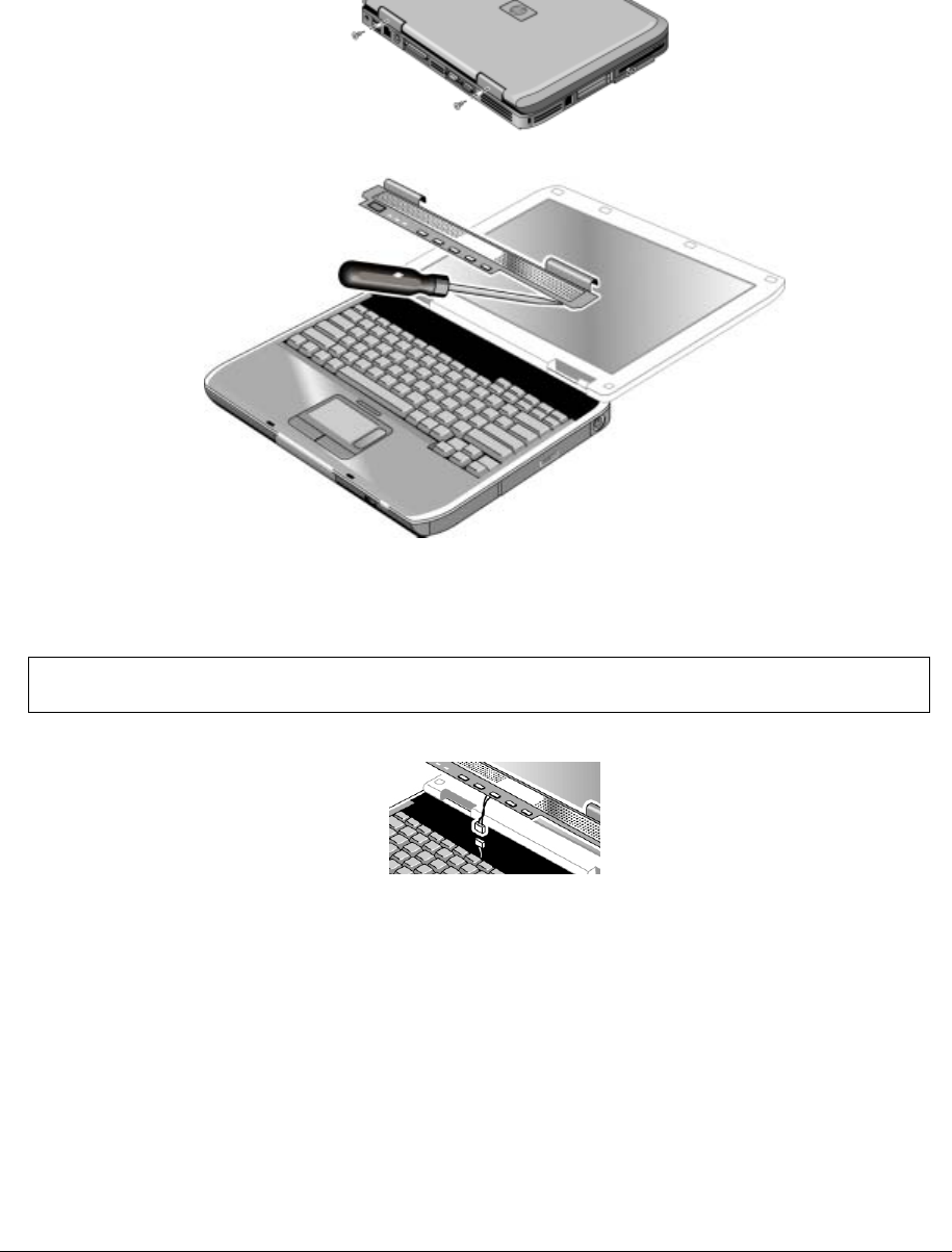
2. Remove the two M2.5×4.0mm hinge cover screws that secure the keyboard cover to the rear of the
notebook.
3. Carefully insert a flat-blade screwdriver blade under the keyboard cover near the right end, then near
the center, then near the left end, and then gently lift up the center of the cover. Gently pry up the hinge
covers if needed, being careful not to damage the plastics or wireless antenna underneath.
CAUTION: Be careful not to damage the antenna PCA that is connected to the left and right
display assembly hinges. Damaging either antenna PCA can degrade notebook performance.
2-14 Removal and Replacement Service Manual
4. If necessary, while holding the center of the cover, carefully insert the flat-blade screwdriver under the
right side of the display assembly hinge, gently pry up, and then lift the cover out. This procedure might
need to be repeated on the left side of display assembly hinge to completely remove the cover.
Figure 2-9. Removing the Keyboard Cover
NOTE: When removing the keyboard cover on HP Pavilion ze5300 and ze5200, HP nx9010, and
Compaq Presario 2500 models, disconnect the speaker cable as indicated in Figure 2-10.
Figure 2-10. Disconnecting the Speaker Cable
Reassembly Note
Insert the tabs on the left- and right-center of the panel into the mating slots under the keyboard, and then
press the panel into place.
Service Manual Removal and Replacement 2-15
Removing the Speaker Assembly
(User-Replaceable)
NOTE: The following speaker assembly removal procedures apply only to HP Pavilion ze4x00,
HP nx9005 and nx9000, Compaq Evo Notebook N1050v and N1010v, and Compaq Presario 2100 and
1100 Series notebooks. The HP Pavilion ze5x00, HP nx9010 and HP nx9008, and Compaq Presario 2500
Series notebook speakers are integrated into the top case. Refer to the “Removing the Top Case” section
later in this chapter for procedures on removing the top case and speakers on the HP Pavilion ze5x00,
HP nx9010 and HP nx9008, and Compaq Presario 2500 Series notebooks.
Required Equipment
1 Phillips screwdriver
Removal Procedure
1. Unplug the AC adapter, if present, and then remove the battery.
2. Remove the keyboard cover (page 2-13).
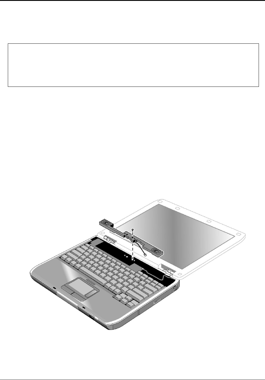
3. Remove the M2.5×6.0mm screw that secures the speaker assembly to the top case.
4. Disconnect the 4-wire cable from the switchboard PCA.
Figure 2-11. Removing the Speaker Assembly

2-16 Removal and Replacement Service Manual
Removing the Keyboard
Required Equipment
1 Phillips screwdriver
Removal Procedure
1. Unplug the AC adapter, if present, and then remove the battery.
2. Remove the keyboard cover (page 2-13).
3. Remove the four M2.5×4.0mm screws that secure the keyboard to the top case.
4. Lift up on the keyboard at the switchboard PCA end, and then pull it toward the display assembly to
release the tabs from the top case.
5. Turn the keyboard over, and then disconnect the motherboard cable.
6. Remove the keyboard.
Reassembly Notes
CAUTION: Do not excessively bend or fold the keyboard cable. Excessive flexing can
damage the keyboard cable connectors.
• Lay the keyboard face down on the top case, forward of its normal position, and then reconnect
the keyboard cable.
• Slide the metal tabs on the bottom of the keyboard into their slots in the top case, and then lower the
keyboard into place.

Service Manual Removal and Replacement 2-17
Figure 2-12. Removing the Keyboard
2-18 Removal and Replacement Service Manual
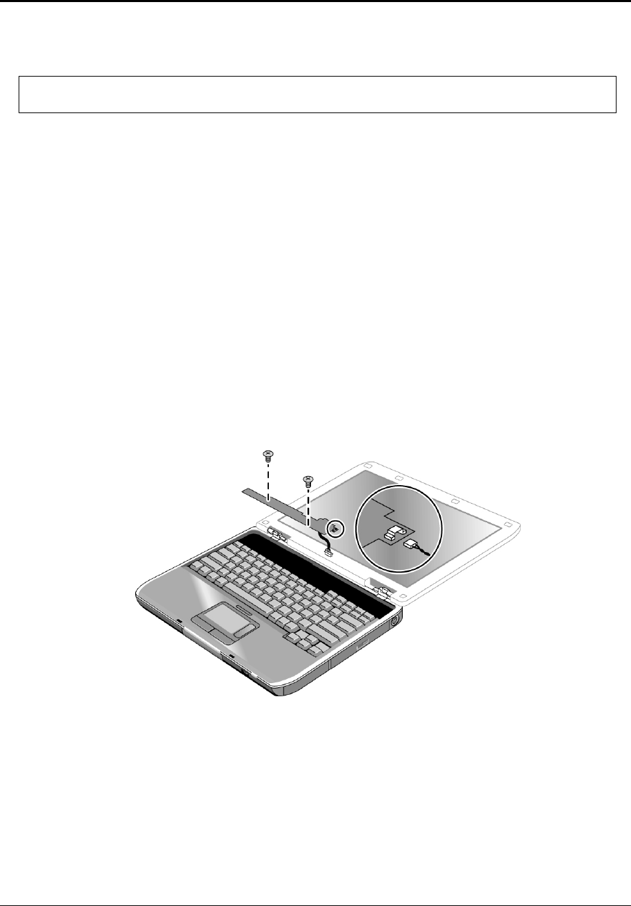
NOTE: This section applies only to HP Pavilion ze4x00, HP nx9005 and nx9000,
Compaq Evo Notebook N1050v and N1010v, and Compaq Presario 2100 and 1100 models.
Required Equipment
1 Phillips screwdriver
Removal Procedure
1. Unplug the AC adapter, if present, and then remove the battery.
2. Remove the keyboard cover (page 2-13).
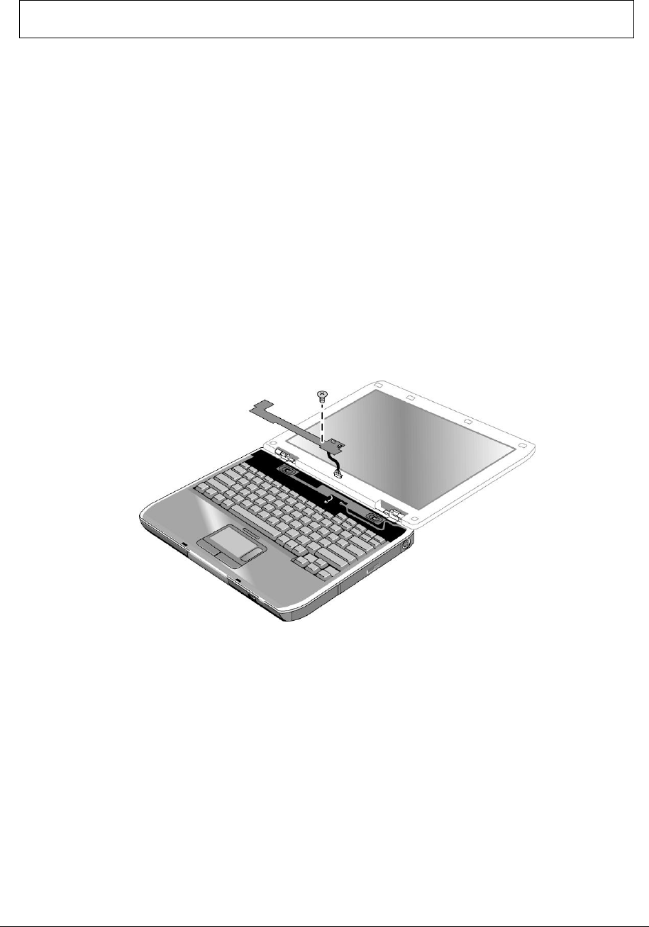
3. Disconnect both the 2-wire and 4-wire cables that connect the switchboard PCA to the top case
and speaker assembly, respectively.
4. Remove the M2.5×4.0mm screw that secures the keyboard, and then switchboard PCA to the
top case (page 2-16).
5. Gently lift up on the keyboard, carefully remove the switchboard PCA from the top case, and then
disconnect the underside motherboard cable.
Figure 2-13. Removing the Switchboard PCA
HP Pavilion ze4x00, HP nx9005 and nx9000,
Compaq Evo Notebook N1050v and N1010v, and
Compaq Presario 2100 and 1100 Models
Service Manual Removal and Replacement 2-19
Removing the Switchboard PCA
NOTE: This section applies only to HP Pavilion ze5x00, HP nx9010 and HP nx9008, and
Compaq Presario 2500 models.
Required Equipment
1 Phillips screwdriver
Removal Procedure
1. Unplug the AC adapter, if present, and then remove the battery.
2. Remove the keyboard cover (page 2-13).
3. Disconnect the 2-wire cable that connects the switchboard PCA to the display lid switch.
4. Remove the two M2.5×4.0mm screws that secure the switchboard PCA to the top case.
5. Gently lift up on the rear right edge of the switchboard PCA to disconnect the PCA from the
motherboard.
6. Remove the switchboard PCA.
Figure 2-14. Removing the Switchboard PCA
HP Pavilion ze5x00,
HP nx9010 and HP nx9008, and
Compaq Presario 2500 Models

2-20 Removal and Replacement Service Manual
Removing the CD/DVD Drive
NOTE: This section applies only to HP Pavilion ze4x00, HP nx9005 and nx9000,
Compaq Evo Notebook N1050v and N1010v, and Compaq Presario 2100 and 1100 models.
Required Equipment
1 Phillips screwdriver
Removal Procedure
1. Unplug the AC adapter, if present, and then remove the battery.
2. Remove these additional assemblies:
• Keyboard cover (page 2-13)
• Keyboard (page 2-16)
Service Manual Removal and Replacement 2-21
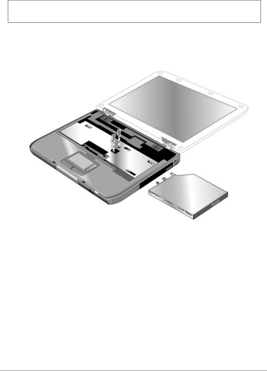
3. Remove the 2 screws that secure the CD/DVD drive to the top case and motherboard.
NOTE: The screws that secure the CD/DVD drive are 2 different sizes. The front screw is a
M2.5×6.0mm screw. The back screw is a M2.5×4.0mm screw. Make sure these screws are installed in the
correct locations when reinstalling the CD/DVD drive.
4. Place your index finger in the top case opening, and then push out on the CD/DVD drive to release it
from the motherboard.
5. Remove the CD/DVD drive.
Figure 2-15. Removing the CD/DVD Drive
HP Pavilion ze4x00, HP nx9005 and nx9000,
Compaq Evo Notebook N1050v and N1010v, and
Compaq Presario 2100 and 1100 Models
2-22 Removal and Replacement Service Manual
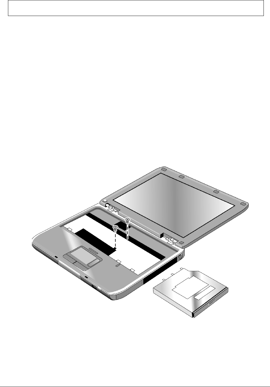
NOTE: This section applies only to HP Pavilion ze5x00, HP nx9010 and HP nx9008, and
Compaq Presario 2500 models.
Required Equipment
1 Phillips screwdriver
Removal Procedure
1. Unplug the AC adapter, if present, and then remove the battery.
2. Remove these additional assemblies:
• Keyboard cover (page 2-13)
• Keyboard (page 2-16)
3. Remove the two M2.5×6.0mm screws that secure the CD/DVD drive to the top case and motherboard.
4. Place your index finger in the top case opening and push out on the CD/DVD drive to release it from
the motherboard.
5. Remove the CD/DVD drive.
Figure 2-16. Removing the CD/DVD Drive
HP Pavilion ze5x00,
HP nx9010 and HP nx9008, and
Compaq Presario 2500 Models

Service Manual Removal and Replacement 2-23
Removing the Display Assembly
(Authorized Service Providers Only)
Required Equipment
1 Phillips screwdriver
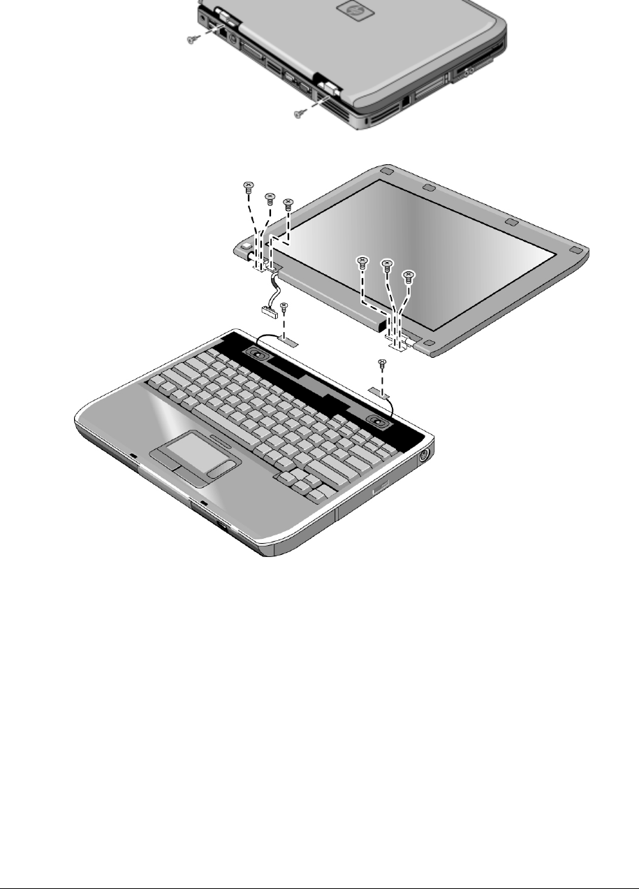
Removal Procedure
1. Unplug the AC adapter, if present, and then remove the battery.
2. Remove the keyboard cover (page 2-13).
3. Remove the two M2.5×6.0mm retaining screws from the notebook rear panel.
4. Remove the M2.5×4.0mm screws from the left and right antenna PCAs. Relocate the antenna PCAs
away from the display assembly hinges.
5. Disconnect the display assembly cable from the motherboard.
6. Remove the six M2.5×6.0mm retaining screws that secure the display assembly to the top case.
(Note that there is a grounding strap at the left hinge.)
7. Lift the display assembly off of the notebook.
2-24 Removal and Replacement Service Manual
Figure 2-17. Removing the Display Assembly

Service Manual Removal and Replacement 2-25
Reassembly Notes
NOTE: After replacing the display assembly or motherboard, you must use the Service Utilities floppy
disk to reprogram the EEPROM on the motherboard for the new display.
1. Download the notebook series service package from the Partnership Web site (see page vii), and
then create a Service Utilities floppy disk as described in the package’s Readme file.
2. Plug in an AC adapter.
3. Insert the Service Utilities floppy disk in the floppy drive. If the unit has no internal floppy drive,
connect a USB floppy drive.
4. Turn on the notebook.
5. When you see the HP logo, press esc to display the boot menu, then boot from the floppy drive.
6. Select the option to update the display/LCD identification stored on the motherboard.
• Make sure you connect the grounding strap to the left display assembly hinge.
• When connecting the left and right antenna PCAs, make sure they are parallel with the display assembly
hinges.

2-26 Removal and Replacement Service Manual
Removing the Top Case
(Authorized Service Providers Only)
NOTE: This section applies only to HP Pavilion ze4x00, HP nx9005 and nx9000,
Compaq Evo Notebook N1050v and N1010v, and Compaq Presario 2100 and 1100 models.
Required Equipment
1 Phillips screwdriver
Removal Procedure
1. Unplug the AC adapter, if present, and remove the battery.
2. Remove these additional assemblies:
• Hard disk drive (page 2-9)
• Keyboard cover (page 2-13)
• Speaker assembly (page 2-23)
• Keyboard (page 2-16)
• Switchboard PCA (page 2-19)
• CD/DVD drive (page 2-20)
• Display assembly (page 2-23)
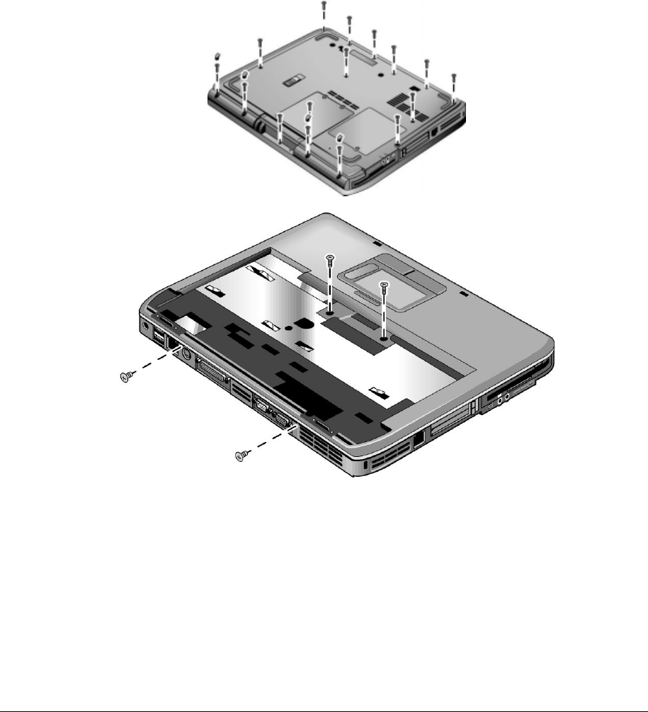
Service Manual Removal and Replacement 2-27
3. Turn the notebook bottom side up with the front facing forward.
4. Remove the following M2.5×4.0mm screws:
• One from the battery bay
• One from the hard disk drive bay
5. Remove the remaining 14 M2.5×6.0mm screws.
6. Turn the notebook top side up with the rear panel facing forward.
7. Remove the two M2.5×4.0mm screws from the rear panel.
8. Remove the two M2.5×6.0mm screws from the top case.
9. Lift the top case off of the notebook and then disconnect the touch pad cable from the motherboard.
Figure 2-18. Removing the Top Case
HP Pavilion ze4x00, HP nx9005 and nx9000,
Compaq Evo Notebook N1050v and N1010v, and
Compaq Presario 2100 and 1100 Models

2-28 Removal and Replacement Service Manual
NOTE: This section applies only to HP Pavilion ze5x00, HP nx9010 and HP nx9008, and
Compaq Presario 2500 models.
Required Equipment
1 Phillips screwdriver
Removal Procedure
1. Unplug the AC adapter, if present, and then remove the battery.
2. Remove these additional assemblies:
• Hard disk drive (page 2-9)
• Keyboard cover (page 2-13)
• Speaker assembly (page 2-15)
• Keyboard (page 2-16)
• Switchboard PCA (page 2-19)
• CD/DVD drive (page 2-20)
• Display assembly (page 2-23)
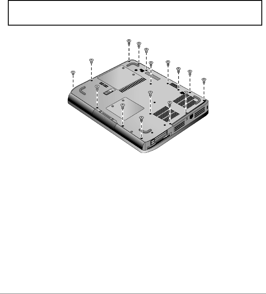
Service Manual Removal and Replacement 2-29
3. Turn the notebook bottom side up with the front facing forward.
4. Remove the following 16 screws:
• Six M2.5×7.0mm screws on the rear edge of the notebook
• Two M2.5×6.0mm screws on each side of the docking connector
• One M2.5×6.0mm screw behind the battery bay
• Three M2.5×7.0mm screws around the middle fan vent
• One M2.5×4.0mm screw in the battery bay
• Three M2.5×7.0mm screws on the front edge of the notebook
CAUTION: The 16 screws removed in step 4 are 3 different lengths. Be sure to note of the
correct location of each screw as it is removed and install it in the correct location. Failure to
follow this caution can result in damage to the notebook.
Figure 2-19. Removing the Top Case Screws
HP Pavilion ze5x00,
HP nx9010 and HP nx9008, and
Compaq Presario 2500 Models
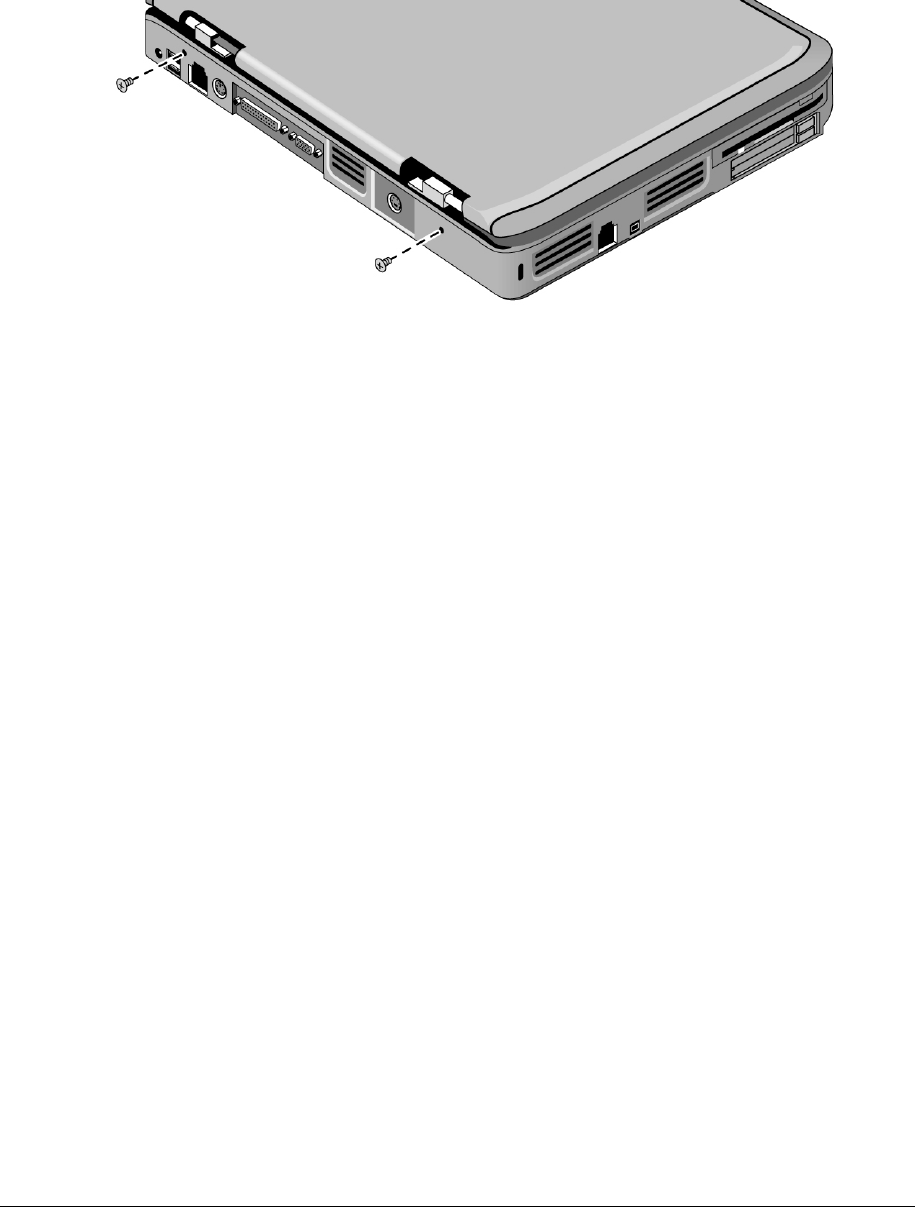
2-30 Removal and Replacement Service Manual
5. Turn the notebook top side up with the rear panel facing forward.
6. Remove the two M2.5×7.0mm screws from the rear of the bottom case.
Figure 2-20. Removing the Top Case Screws
HP Pavilion ze5x00,
HP nx9010 and HP nx9008, and
Compaq Presario 2500 Models
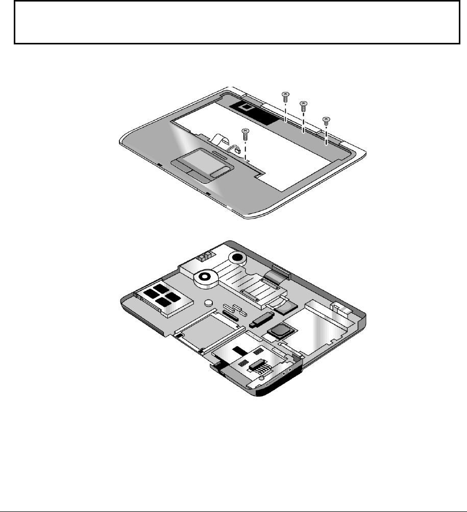
Service Manual Removal and Replacement 2-31
7. Position the notebook so the front faces forward.
8. Disconnect the floppy drive flex cable from the low insertion force (LIF) connector to which it is
connected.
9. Release the ZIF connector to which the TouchPad cable is connected, and then disconnect the
TouchPad cable from the system board.
10. Remove the following 4 screws:
• One M2.5×7.0mm screw next to the TouchPad cable
• Two M2.5×6.0mm screws in the center of the top case
• One M2.5×4.0mm screw on the right side of the top case
CAUTION: The 4 screws removed in step 10 are 3 different lengths. Be sure to note of the
correct location of each screw as it is removed and install it in the correct location. Failure to
follow this caution can result in damage to the notebook.
11. Lift the top case off of the notebook.
Figure 2-21. Removing the Top Case
HP Pavilion ze5x00,
HP nx9010 and HP nx9008, and
Compaq Presario 2500 Models

2-32 Removal and Replacement Service Manual
Removing the Floppy Drive
(Authorized Service Providers Only)
NOTE: This section applies only to HP Pavilion ze4x00, HP nx9005 and nx9000,
Compaq Evo Notebook N1050v and N1010v, and Compaq Presario 2100 and 1100 models.
Required Equipment
1 Phillips screwdriver
Removal Procedure
1. Unplug the AC adapter, if present, and remove the battery.
2. Remove these additional assemblies:
• Hard disk drive (page 2-9)
• Keyboard cover (page 2-13)
• Keyboard (page 2-16)
• Switchboard PCA (page 2-19)
• Display assembly (page 2-23)
• Top case (page 2-26)
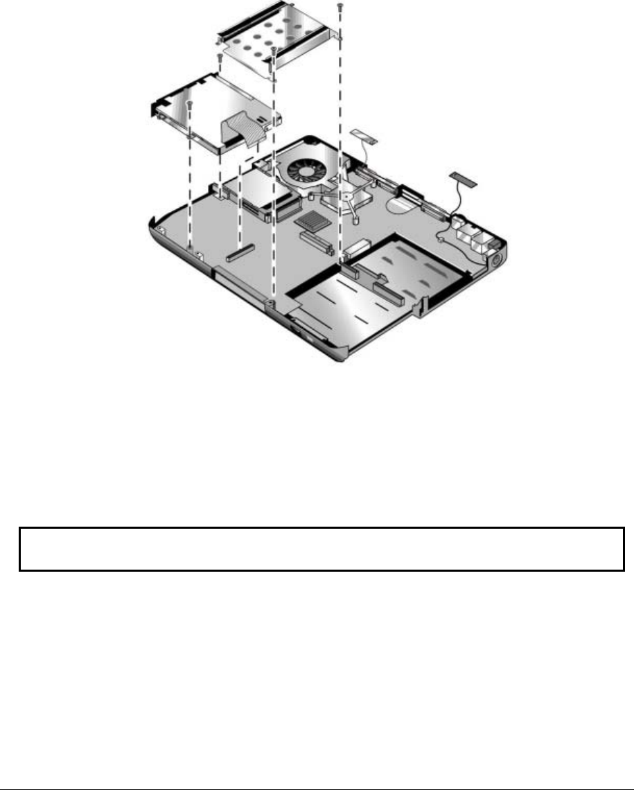
Service Manual Removal and Replacement 2-33
3. Remove the two M2.5×4.0mm screws (right side) that secure the hard disk drive guide to the
motherboard. (Note that the screws (left side) are missing. These screws were removed during the
top case removal procedure.)
4. Disconnect the motherboard cable.
5. Remove the two M2.5×4.0mm screws that secure the floppy drive to the motherboard.
6. Remove the floppy drive.
Figure 2-22. Removing the Floppy Drive
HP Pavilion ze4x00, HP nx9005 and nx9000,
Compaq Evo Notebook N1050v and N1010v, and
Compaq Presario 2100 and 1100 Models
Reassembly Notes
CAUTION: Do not excessively bend or fold the floppy drive cable. Excessive flexing can
damage the floppy drive cable connections.
• Connect the floppy drive cable to the motherboard prior to replacing the floppy drive and hard disk
drive guide.
• When replacing the hard disk drive guide, do not secure the left side to the motherboard. The left side
of the guide gets secured during the top case replacement procedure.

2-34 Removal and Replacement Service Manual
NOTE: This section applies only to HP Pavilion ze5x00, HP nx9010 and HP nx9008, and
Compaq Presario 2500 models.
Required Equipment
• 1 Phillips screwdriver
Removal Procedure
1. Unplug the AC adapter, if present, and then remove the battery.
2. Remove these additional assemblies:
• Hard disk drive (page 2-9)
• Keyboard cover (page 2-13)
• Keyboard (page 2-16)
• Switchboard PCA (page 2-19)
• Display assembly (page 2-23)
• Top case (page 2-26)
3. Remove the insulating tape that secures the floppy drive flex cable to the TouchPad bracket on
the top case.
4. Remove the four M2.5×6.0mm screws that secure the floppy drive and floppy drive bezel to
the top case.
5. Remove the floppy drive.
6. Remove the M2.0×3.0mm screw that secures the floppy drive bezel to the floppy drive.
7. Remove the floppy drive bezel.
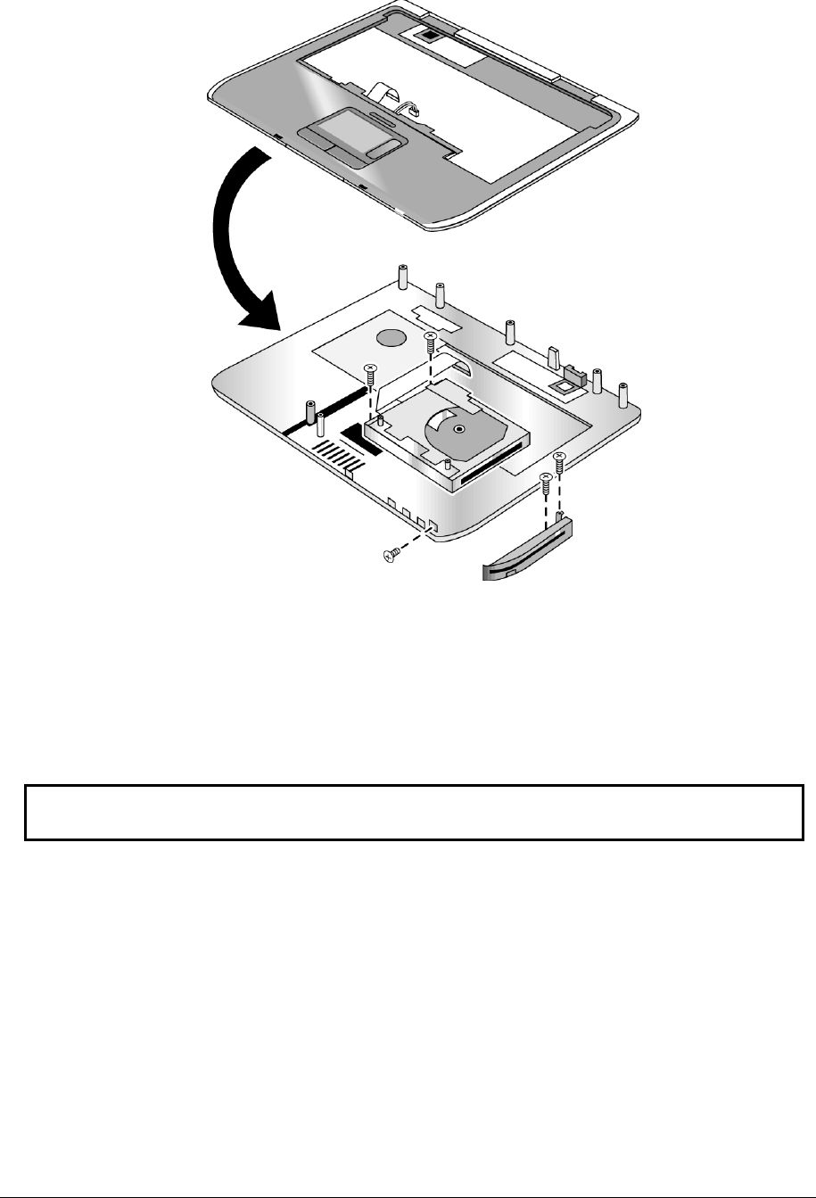
Service Manual Removal and Replacement 2-35
Figure 2-23. Removing the Floppy Drive
HP Pavilion ze5x00,
HP nx9010 and HP nx9008, and
Compaq Presario 2500 Models
Reassembly Notes
CAUTION: Do not excessively bend or fold the floppy drive cable. Excessive flexing can
damage the floppy drive cable connections.

2-36 Removal and Replacement Service Manual
Removing the Infrared (I/R) PCA
(Authorized Service Providers Only)
Required Equipment
1 Phillips screwdriver
Removal Procedure
1. Unplug the AC adapter, if present, and then remove the battery.
2. Remove these additional assemblies:
• Hard disk drive (page 2-9)
• Keyboard cover (page 2-13)
• Keyboard (page 2-16)
• Switchboard PCA (page 2-19)
• Display assembly (page 2-23)
• Top case (page 2-26)
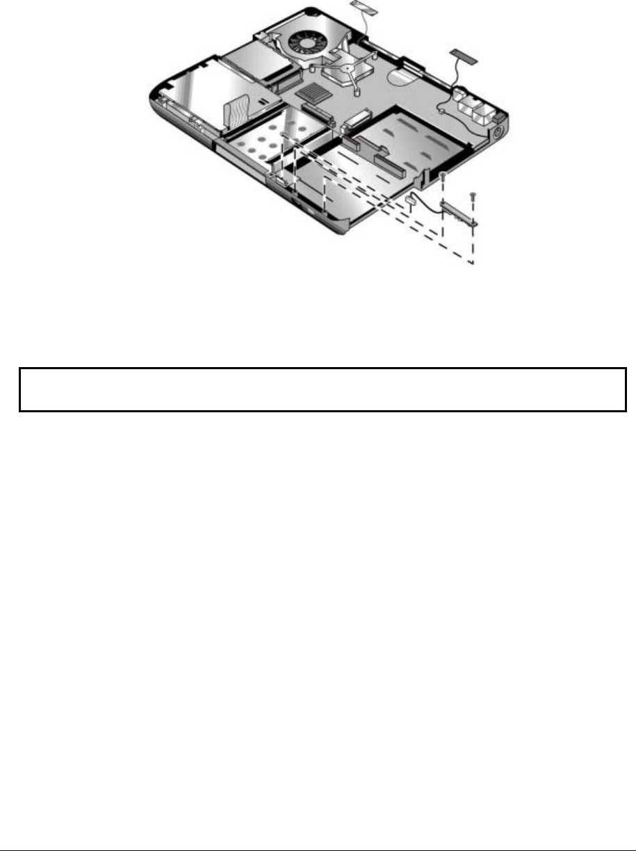
Service Manual Removal and Replacement 2-37
3. Disconnect the I/R PCA cable from the motherboard.
4. Remove the two M2.5×4.0mm screws that secure the I/R PCA to the bottom case.
5. Remove the I/R PCA.
Figure 2-24. Removing the I/R PCA
Reassembly Note
CAUTION: Use care when handling the I/R PCA cable. Damaging the cable can degrade
notebook performance.
Make sure you route the I/R PCA cable between the left screw hole and the bottom case.

2-38 Removal and Replacement Service Manual
Removing the Audio PCA
(Authorized Service Providers Only)
NOTE: The following audio PCA removal instructions apply only to HP Pavilion ze5300 and ze5200,
HP nx9010, and Compaq Presario 2500 models.
Required Equipment
1 Phillips screwdriver
Removal Procedure
1. Unplug the AC adapter, if present, and then remove the battery.
2. Remove these additional assemblies:
• Hard disk drive (page 2-9)
• Keyboard cover (page 2-13)
• Keyboard (page 2-16)
• Switchboard PCA (page 2-19)
• Display assembly (page 2-23)
• Top case (page 2-26)
3. Disconnect the audio PCA cable from the motherboard.
4. Remove the audio PCA cable from the clip on the bottom case.
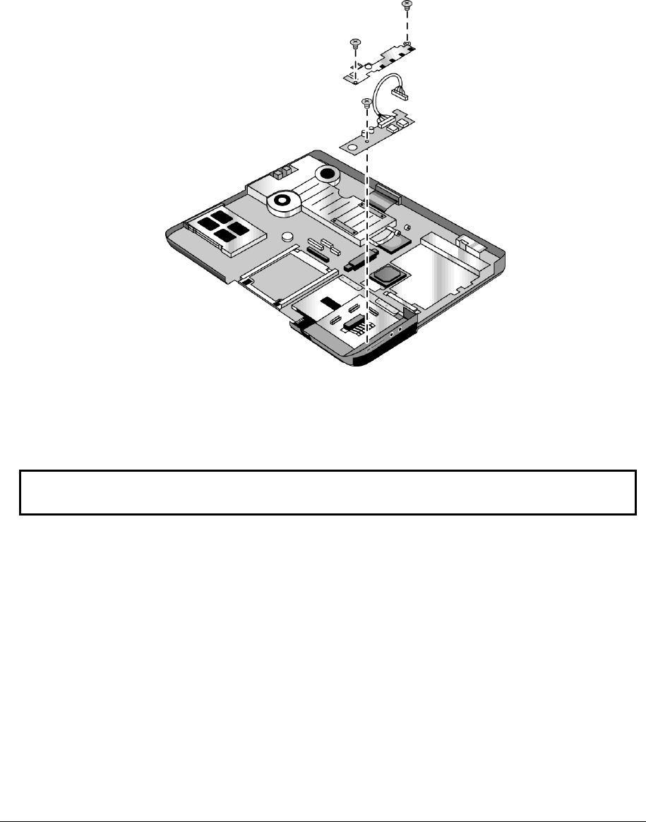
Service Manual Removal and Replacement 2-39
5. Remove the two M2.0×3.0mm flathead screws that secure the audio PCA shield to the
bottom case.
6. Remove the audio PCA shield.
7. Remove the M2.0×3.0mm flathead screw that secures the audio PCA to the bottom case.
8. Remove the audio PCA.
Figure 2-25. Removing the Audio PCA
Reassembly Note
CAUTION: Use care when handling the audio PCA cable. Damaging the cable can degrade
notebook performance.
Make sure you route the audio PCA cable into the clip on the bottom case.

2-40 Removal and Replacement Service Manual
Removing the Heat Sink (with Fan)
(Authorized Service Providers Only)
NOTE: This section applies only to HP Pavilion ze4x00, HP nx9005 and nx9000,
Compaq Evo Notebook N1050v and N1010v, and Compaq Presario 2100 and 1100 models.
Required Equipment
0 Phillips screwdriver
Removal Procedure
1. Unplug the AC adapter, if present, and then remove the battery.
2. Remove these additional assemblies:
• Hard disk drive (page 2-9)
• Keyboard cover (page 2-13)
• Keyboard (page 2-16)
• Switchboard PCA (page 2-19)
• Display assembly (page 2-23)
• Top case (page 2-26)
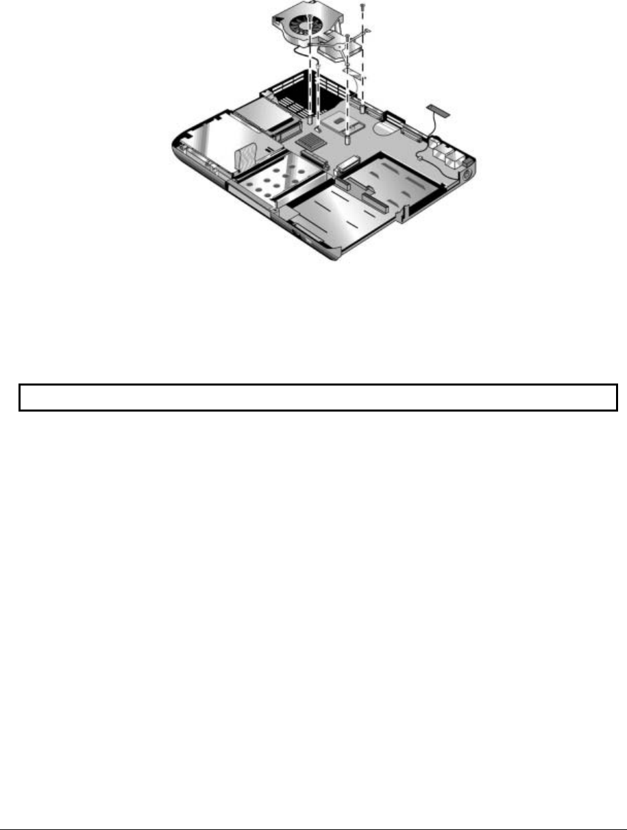
Service Manual Removal and Replacement 2-41
3. Remove the three M2.5×4.0mm retaining screws.
4. Lift up on the heat sink (with fan), and then disconnect the fan cable from the motherboard.
Figure 2-26. Removing the Heat Sink (with Fan)
HP Pavilion ze4x00, HP nx9005 and nx9000,
Compaq Evo Notebook N1050v and N1010v, and
Compaq Presario 2100 and 1100 Models
CAUTION: Do not spin the fan blades with your finger or you could damage the fan’s bearings.
Reassembly Notes
• If the thermal pad is damaged, use a sharp knife or scraper to carefully remove it from the heat sink, and
then attach a new thermal pad.
• Install the heat sink screws in this order:
1. Install all 3 screws lightly.
2. Fully tighten the screws in the order marked on the heat sink.

2-42 Removal and Replacement Service Manual
NOTE: This section applies only to HP Pavilion ze5x00, HP nx9010 and HP nx9008, and
Compaq Presario 2500 models.
Required Equipment
0 Phillips screwdriver
Removal Procedure
1. Unplug the AC adapter, if present, and then remove the battery.
2. Remove these additional assemblies:
• Hard disk drive (page 2-9)
• Keyboard cover (page 2-13)
• Keyboard (page 2-16)
• Switchboard PCA (page 2-19)
• Display assembly (page 2-23)
• Top case (page 2-26)
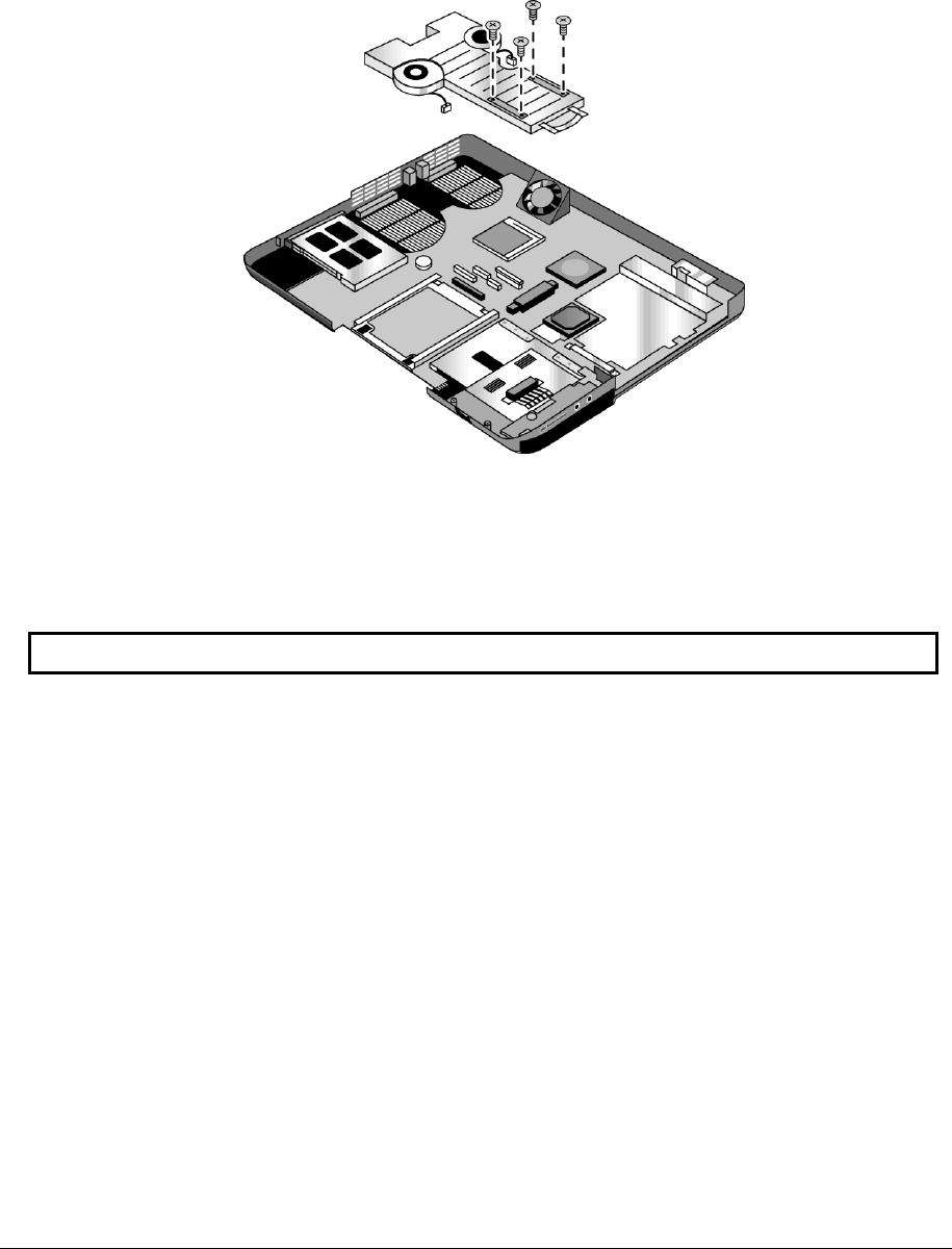
Service Manual Removal and Replacement 2-43
3. Disconnect the 2 fan cables from the motherboard.
4. Remove the 4 retaining M2.0×5.0mm screws in the “1,” “2,” “3,” “4” sequence stamped on the
heat sink.
5. Lift up on the heat sink (with fan).
Figure 2-27. Removing the Heat Sink (with Fan)
HP Pavilion ze5x00,
HP nx9010 and HP nx9008, and
Compaq Presario 2500 Models
CAUTION: Do not spin the fan blades with your finger or you could damage the fan’s bearings.
Reassembly Notes
• If the thermal pad is damaged, use a sharp knife or scraper to carefully remove it from the heat sink, and
then attach a new thermal pad.
• Install the heat sink screws in this order:
1. Install all 4 screws lightly.
2. Fully tighten the screws in the order stamped on the heat sink.

2-44 Removal and Replacement Service Manual
Removing the CPU Module
(Authorized Service Providers Only)
Required Equipment
Small flat-blade screwdriver
NOTE: This section applies only to HP Pavilion ze4x00, HP nx9005 and nx9000,
Compaq Evo Notebook N1050v and N1010v, and Compaq Presario 2100 and 1100 models.
Removal Procedure
1. Unplug the AC adapter, if present, and then remove the battery.
2. Remove these additional assemblies:
• Hard disk drive (page 2-9)
• Keyboard cover (page 2-13)
• Keyboard (page 2-16)
• Switchboard PCA (page 2-19)
• Display assembly (page 2-23)
• Top case (page 2-26)
• Heat sink (page 2-40)
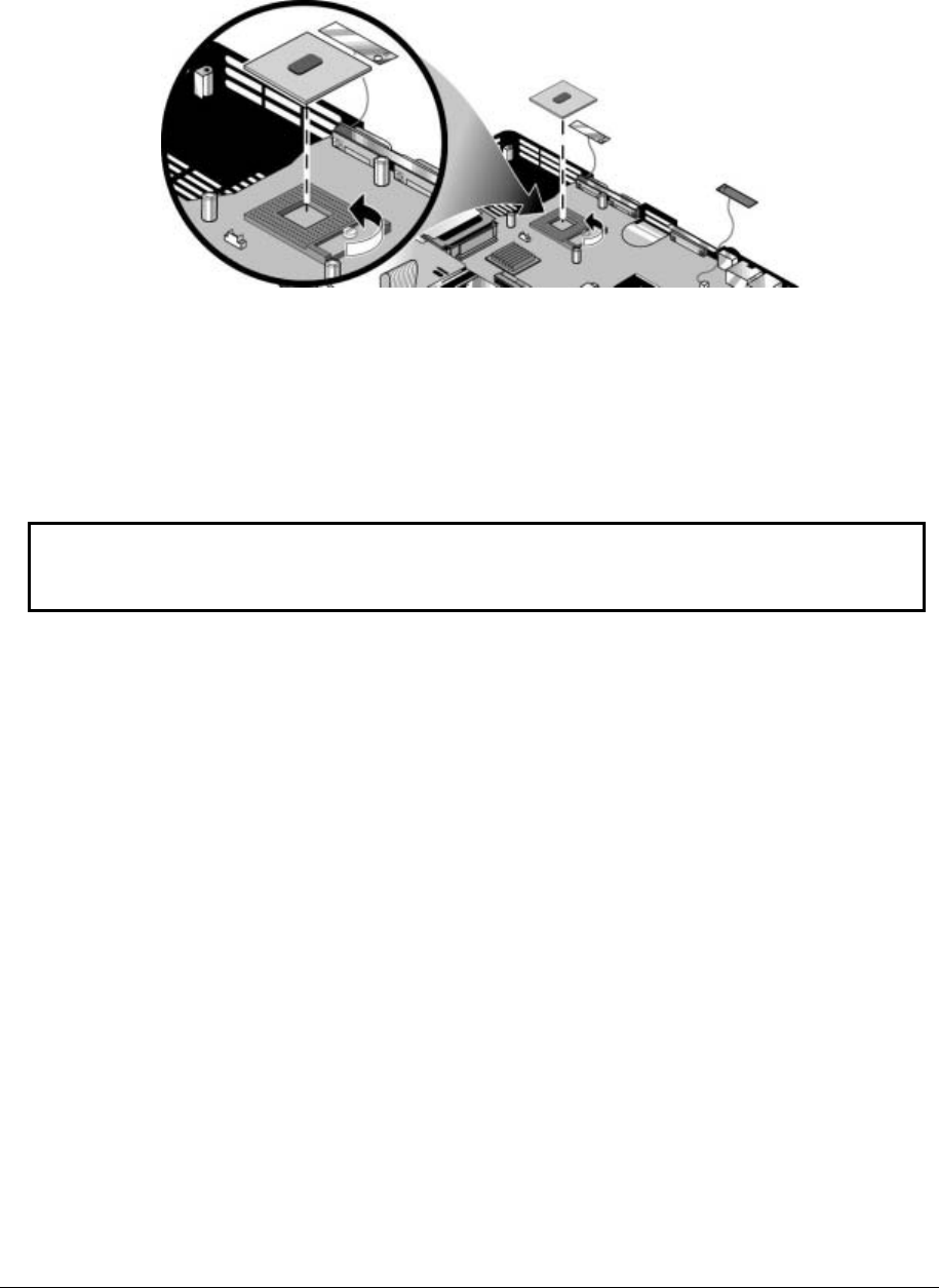
Service Manual Removal and Replacement 2-45
3. Turn the lock screw one-half turn counterclockwise to release the CPU module (you should hear a
light snap). Carefully lift the CPU module off of its socket on the motherboard.
Figure 2-28. Removing the CPU Module
HP Pavilion ze4x00, HP nx9005 and nx9000,
Compaq Evo Notebook N1050v and N1010v, and
Compaq Presario 2100 and 1100 Models
Reassembly Notes
CAUTION: Each time you install a new CPU module, you must also replace the heat sink’s
thermal pad to maintain optimum heat transfer. Use a sharp knife or scraper to carefully remove
the old thermal pad from the heat sink, and then attach the new thermal pad.
• The CPU module is keyed for installation, and can be inserted only one way.
• Carefully insert the CPU module into the motherboard, and then turn the lock screw one-half turn
clockwise to secure the CPU module.
• Be sure to replace the thermal pad on the heat sink, as described in the reassembly notes on
page 2-41.

2-46 Removal and Replacement Service Manual
NOTE: This section applies only to HP Pavilion ze5x00, HP nx9010 and HPnx9008, and
Compaq Presario 2500 models.
Removal Procedure
1. Unplug the AC adapter, if present, and then remove the battery.
2. Remove these additional assemblies:
• Hard disk drive (page 2-9)
• Keyboard cover (page 2-13)
• Keyboard (page 2-16)
• Switchboard PCA (page 2-19)
• Display assembly (page 2-23)
• Top case (page 2-26)
• Heat sink (page 2-40)
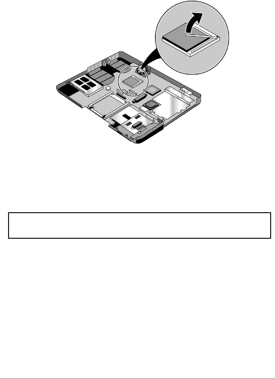
Service Manual Removal and Replacement 2-47
3. Slide the front tip of the locking arm slightly to the right, and then swing it up and back.
4. Carefully lift the CPU module off of its socket on the motherboard.
Figure 2-29. Removing the CPU Module
HP Pavilion ze5x00,
HP nx9010 and HPnx9008, and
Compaq Presario 2500 Models
Reassembly Notes
CAUTION: Each time you install a new CPU module, you must also replace the heat sink’s
thermal pad to maintain optimum heat transfer. Use a sharp knife or scraper to carefully
remove the old thermal pad from the heat sink, and then attach the new thermal pad.
• The CPU module is keyed for installation, and can be inserted only one way.
• Carefully insert the CPU module into the motherboard, and then swing the locking arm forward
and down. Make sure the clip on the right side of the CPU module socket secures the locking arm.
• Be sure to replace the thermal pad on the heat sink, as described in the reassembly notes on
page 2-41.

2-48 Removal and Replacement Service Manual
Removing the RJ11/1394 Connector Module
(Authorized Service Providers Only)
NOTE: The following RJ11/1394 connector module removal instructions apply only to
HP Pavilion ze5x00, HP nx9010 and HP nx9008, and Compaq Presario 2500 models.
Required Equipment
Small flat-blade screwdriver
Removal Procedure
1. Unplug the AC adapter, if present, and then remove the battery.
2. Remove these additional assemblies:
• Hard disk drive (page 2-9)
• Keyboard cover (page 2-13)
• Keyboard (page 2-16)
• Switchboard PCA (page 2-19)
• Display assembly (page 2-23)
• Top case (page 2-26)
• Heat sink (page 2-40)
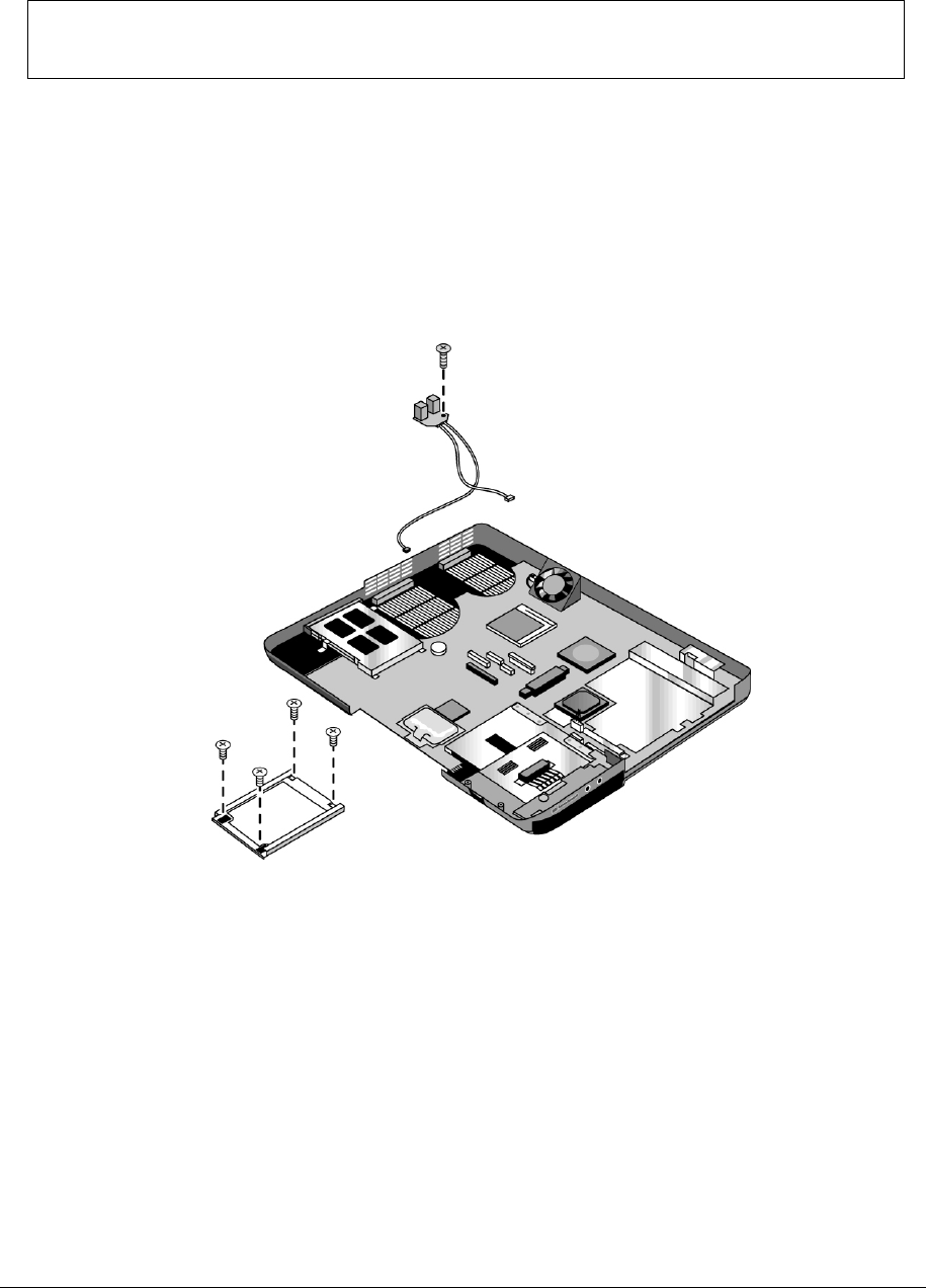
Service Manual Removal and Replacement 2-49
3. Remove the 4 screws that secure the hard disk drive guide to the bottom case.
NOTE: The 4 screws that secure the hard disk drive guide are 2 different sizes. The screw in the upper
left corner is a M2.5x6.0mm screw. The remaining 3 screws are M2.0×4.0mm screws. Make sure these
screws are installed in the correct locations when reinstalling the hard disk drive guide.
4. Remove the hard disk drive guide.
5. Disconnect the modem cable from the motherboard.
6. Disconnect the 1394 cable from the motherboard.
7. Remove the M2.5×6.0mm screw that secures the RJ11/1394 connector module to the bottom case.
8. Remove the RJ11/1394 connector module.
Figure 2-30. Removing the RJ11/1394 Connector Module
HP Pavilion ze5x00,
HP nx9010 and HP nx9008, and
Compaq Presario 2500 Models

2-50 Removal and Replacement Service Manual
Removing the Motherboard
(Authorized Service Providers Only)
NOTE: This section applies only to HP Pavilion ze4x00, HP nx9005 and nx9000,
Compaq Evo Notebook N1050v and N1010v, and Compaq Presario 2100 and 1100 models.
Required Equipment
1 Phillips screwdriver
Removal Procedure
NOTE: Before Replacing the Motherboard
If possible, record the computer’s electronic serial number before you replace the motherboard. You will
then store the electronic serial number in the EEPROM on the new motherboard using the Service Utility
floppy disk.
1. Download the notebook service package from the Partnership Web site (see page vii), and then
create a Service Utilities floppy disk as described in the package’s Readme file.
2. Plug in an AC adapter.
3. Insert the Service Utilities floppy disk in the floppy drive.
4. Turn on the notebook. When the HP logo appears (on either the built-in display or the
external monitor), press esc to display the boot menu, and then choose Removable Device and
boot from the floppy disk.
5. Select the Serial Number option from the boot menu.
6. When prompted, type A for the automatic update option. This stores the current system data from
the old motherboard on the floppy disk.
1. Unplug the AC adapter, if present, and then remove the battery.
2. Remove these additional assemblies:
• Hard disk drive (page 2-9)
• Keyboard cover (page 2-13)
• Keyboard (page 2-16)
• CD/DVD drive (page 2-20)
• Display assembly (page 2-23)
• Top case (page 2-26)
• Floppy drive (page 2-32)
• Heat sink (page 2-40)
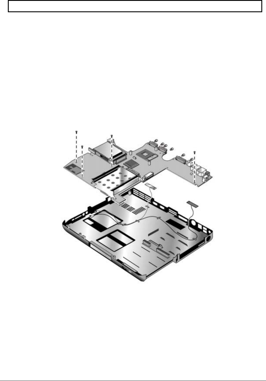
Service Manual Removal and Replacement 2-51
CAUTION: Wireless Models
Be careful when removing and attaching antenna cables. Damage to cables or connectors can degrade
performance.
3. Wireless models only. Remove the Mini PCI door and unplug the 2 antenna cables from the
Mini PCI card. Do not remove the Mini PCI card at this time.
4. Remove the four M2.5×4.0mm screws that attach the motherboard to the bottom case.
5. From the back of the notebook, remove the 6 standoffs (2 each from the external monitor port,
serial port, and parallel port).
6. Remove the antenna cable from the metal holder on the motherboard.
7. Carefully lift the motherboard out of the bottom case.
8. If present, remove the modem port cover.
Figure 2-31. Removing the Motherboard
HP Pavilion ze4x00, HP nx9005 and nx9000,
Compaq Evo Notebook N1050v and N1010v, and
Compaq Presario 2100 and 1100 Models

2-52 Removal and Replacement Service Manual
NOTE: This section applies only to HP Pavilion 5x00, HP nx9010, HP nx9008, and
Compaq Presario 2500 models.
Required Equipment
1 Phillips screwdriver
Removal Procedure
NOTE: Before Replacing the Motherboard
If possible, record the computer’s electronic serial number before you replace the motherboard. You will
then store the electronic serial number in the EEPROM on the new motherboard using the Service Utility
floppy disk.
1. Download the notebook service package from the Partnership Web site (see page vii), and create a
Service Utilities floppy disk as described in the package’s Readme file.
2. Plug in an AC adapter.
3. Insert the Service Utilities floppy disk in the floppy drive.
4. Turn on the notebook. When the HP logo appears (on either the built-in display or the external
monitor), press esc to display the boot menu, and then choose Removable Device and boot from the
floppy disk.
5. Select the Serial Number option from the boot menu.
6. When prompted, type A for the automatic update option. This stores the current system data from
the old motherboard on the floppy disk.
1. Unplug the AC adapter, if present, and then remove the battery.
2. Remove these additional assemblies:
• Hard disk drive (page 2-9)
• Keyboard cover (page 2-13)
• Keyboard (page 2-16)
• CD/DVD drive (page 2-20)
• Display assembly (page 2-23)
• Top case (page 2-26)
• Heat sink (page 2-40)
• Floppy drive (page 2-32)
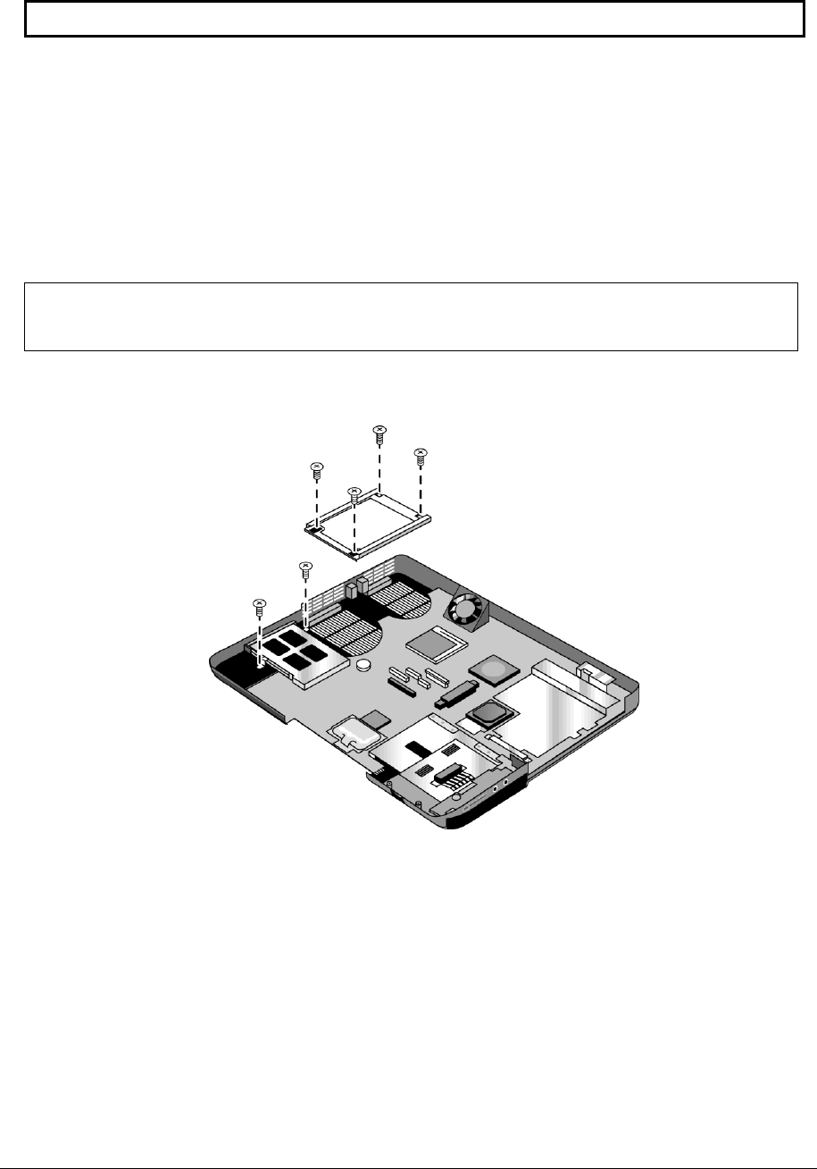
Service Manual Removal and Replacement 2-53
CAUTION: Wireless Models
Be careful when removing and attaching antenna cables. Damage to cables or connectors can degrade
performance.
3. Wireless models only: Remove the Mini PCI door, and then unplug the 2 antenna cables from the Mini
PCI card. Do not remove the Mini PCI card at this time.
4. Remove the two M2.0×4.0mm screws that secure the PCMCIA assembly to the bottom case.
5. Remove the 4 screws that secure the hard disk drive guide to the bottom case.
NOTE: The 4 screws that secure the hard disk drive guide are 2 different sizes. The screw in the upper
left corner is a M2.5×6.0mm screw. The remaining 3 screws are M2.0×4.0mm screws. Make sure these
screws are installed in the correct locations when reinstalling the hard disk drive guide.
6. Remove the hard disk drive guide.
Figure 2-32. Removing the Hard Disk Drive Guide
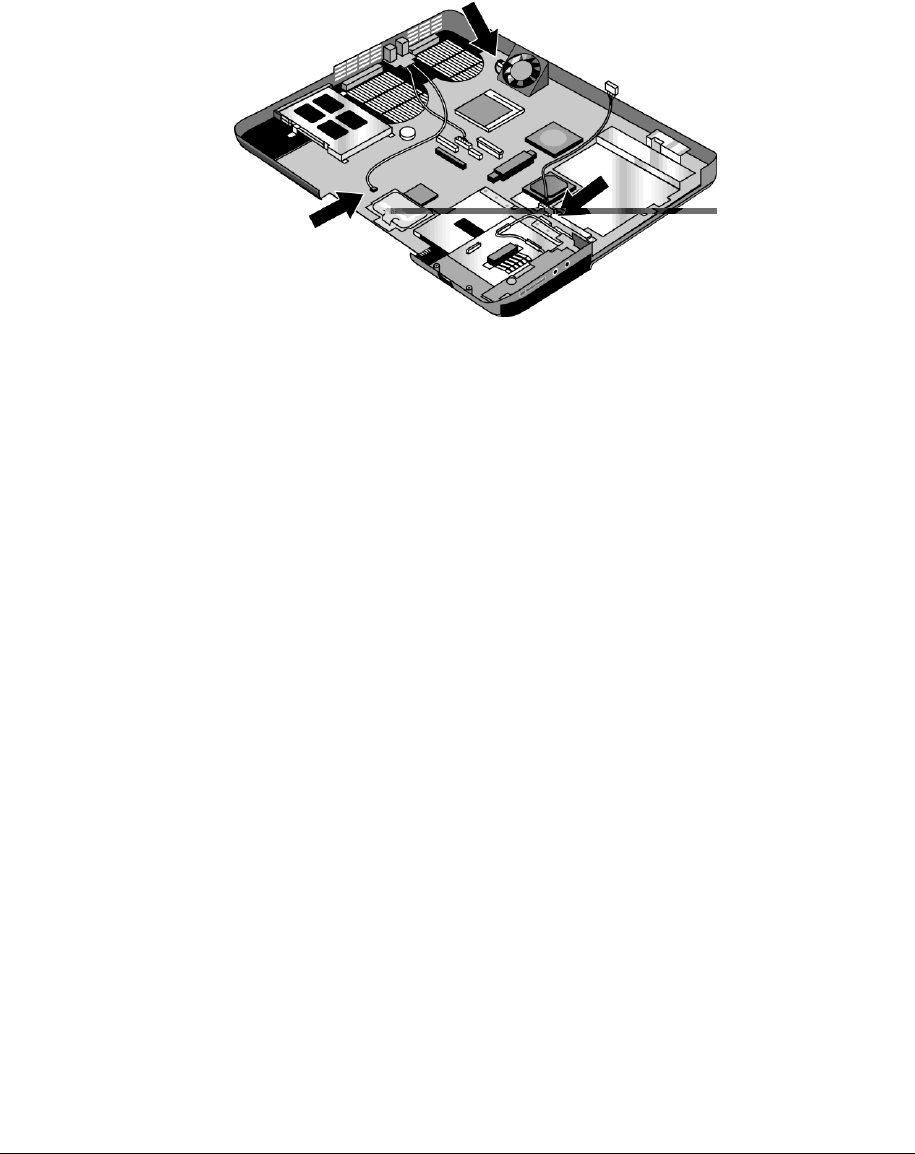
2-54 Removal and Replacement Service Manual
7. Disconnect the modem board cable from the motherboard.
8. Disconnect the 1394 board cable from the motherboard.
9. Disconnect the fan cable from the motherboard and remove the fan.
10. Disconnect the audio board cable from the motherboard.
Figure 2-33. Disconnecting the Motherboard Cables

Service Manual Removal and Replacement 2-55
11. Remove the four M5.0×10mm standoffs from the notebook rear panel (2 on each side of the parallel
and external monitor connectors).
12. Remove the three M2.5×6.0mm screws that secure the CD/DVD drive rear alignment rail to the bottom
case.
13. Remove the CD/DVD drive rear alignment rail.
14. Remove the 2 screws that secure the CD/DVD drive front alignment rail to the bottom case.
NOTE: The 2 screws that secure the CD/DVD drive front alignment rail to the bottom case are
2 different sizes. The screw that secures the left side of the rail is a M2.0×4.0mm screw. The screw that
secures the right side of the rail is a M2.5×6.0mm countersink screw. Make sure these screws are
installed in the correct locations when reinstalling the CD/DVD drive front alignment rail.
15. Remove the CD/DVD drive front alignment rail.
16. Remove the two M2.5×6.0mm countersink screws (one on the front edge of the motherboard, the other
on the left edge of the motherboard) that secure the motherboard to the bottom case.
17. Remove the two M2.0×5.0mm screws that secure the motherboard to the bottom case on the back edge
of the motherboard.
18. Remove the antenna cable from the metal holder on the motherboard.
19. Carefully lift the motherboard out of the bottom case.
20. If present, remove the modem port cover.
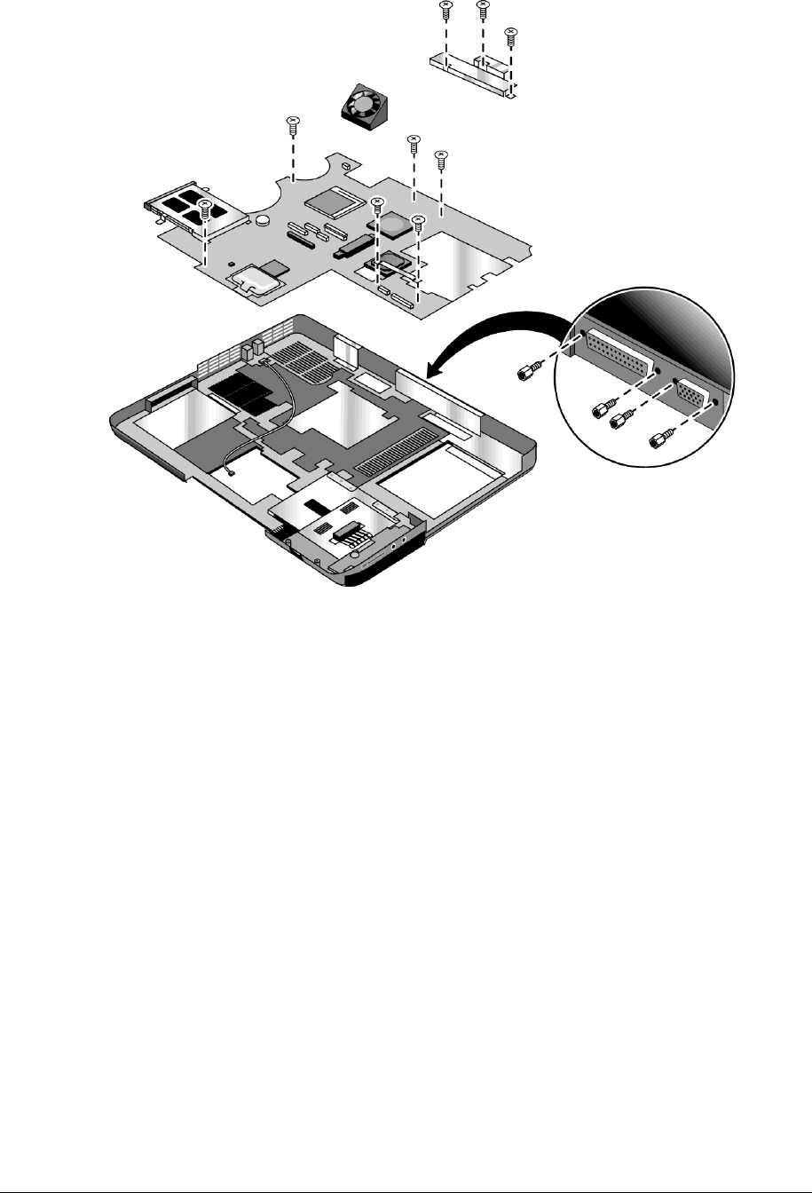
2-56 Removal and Replacement Service Manual
Figure 2-34. Removing the Motherboard
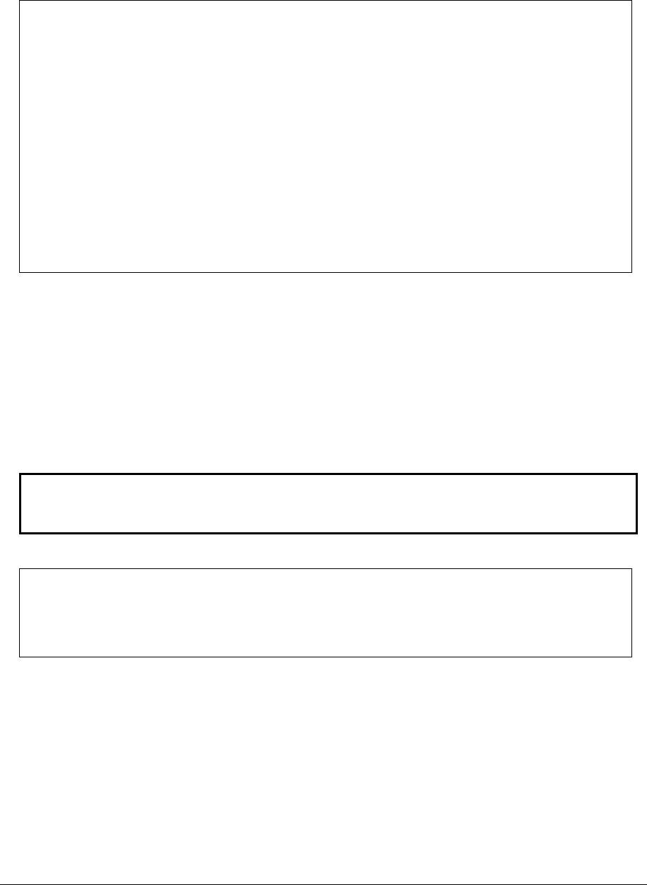
Service Manual Removal and Replacement 2-57
Reassembly Notes
NOTE: After replacing the display assembly or motherboard, you must use the Service Utilities floppy
disk to reprogram the EEPROM on the motherboard for the new display.
1. Download the notebook Series service package from the Partnership Web site (see page vii), and
create a Service Utilities floppy disk as described in the package’s Readme file.
2. Plug in an AC adapter.
3. Insert the Service Utilities floppy disk in the floppy drive. If the unit has no internal floppy drive,
connect a USB floppy drive.
4. Turn on the notebook.
5. When you see the HP logo, press esc to display the boot menu, and then boot from the floppy drive.
6. Select the option to update the display/LCD identification stored on the motherboard.
If you are replacing the CPU module, you must also replace the thermal pad on the heat sink
(see page 2-41).
Wireless Models Only
• Before installing the motherboard, make sure the round coaxial cables from the antenna PCAs are held
in place by the clips in the bottom case.
• Make sure there is sufficient length to the front antenna PCA cables so they can easily be connected to
the Mini PCI card.
Reassembly Procedure
CAUTION: Be extremely careful when replacing the motherboard. The motherboard has EMI
springs attached to it that can bend very easily. Bending any EMI spring could cause a
motherboard short.
NOTE: Reprogramming the BIOS IC
A new BIOS IC contains only enough basic programming to enable the notebook to boot. After installing
a new motherboard, you must reprogram the BIOS IC, preferably with the latest
BIOS—(see page 2-60.)

2-58 Removal and Replacement Service Manual
21. Remove the following components from the old motherboard, and then install onto the new
motherboard:
• CPU module
• Wireless LAN Mini PCI card (if present)
• SDRAM modules
22. Follow the reassembly notes in the section entitled “Removing the Motherboard” on page 2-50.
NOTE: After Replacing the Motherboard
If present, insert the modem port cover into the modem port opening. Afterwards, you must use
the Service Utility floppy disk to store the system data and display information in the EEPROM on the
new motherboard. To do so:
1. Plug in an AC adapter.
2. Insert the Service Utilities floppy disk in the floppy drive.
3. Turn on the notebook.
4. If you hear 5 beeps, press F1 to update the display data stored on the motherboard. Let the notebook
reboot, and then go to the next step.
5. Select the Serial Number option from the boot menu.
6. If you successfully stored system data on the floppy disk before removing the old motherboard,
type A for the automatic update. This restores the old system data on the new motherboard.
If you did not store system data, type M for the manual update option. Enter the serial number from the
bottom of the notebook—you might have to contact an HP support center to do this.

Service Manual Removal and Replacement 2-59
Replacing Components on a Bottom Case
Reassembly Procedure
1. Transfer the plastic wireless panel, and if present, the docking port cover from the old bottom case to
the new bottom case.
2. Install a new Microsoft Product ID label.
3. Transfer the old serial number label, and then install a new overlay, or create a new serial number label
using the steps below.
4. Follow the “Reassembly Notes” on page 2-52.
Installing a New Serial Number Label
Download the latest version of the serial number label template (Microsoft Word format) from the
Partnership Web site (see page vii) under Support/Service in Technical Support Information. The latest
version includes fields for warranty period and manufacturing location. Store the template with other
Word templates on a PC connected to a laser printer.
5. Open a new document based on the serial label template.
6. Enter the information from the old serial label, and then print the new label on plain white paper.
(The new label does not have barcodes.)
7. Carefully cut out the new serial label just inside the border, and then place it into the inner recess in the
bottom case. The bottom of the label goes toward the front of the case.
8. Make sure all regulatory labels that were on the old bottom case are also on the new bottom case.
9. While holding the paper label in place, attach a serial label overlay into the outer recess. The overlay
covers and protects the serial label.
HP Serial Number (S)TW711A1234 1YR
(1P) F2072 W EA MFG TW711A1234
Made in Taiwan
Figure 2-35. Example of Serial Number Label
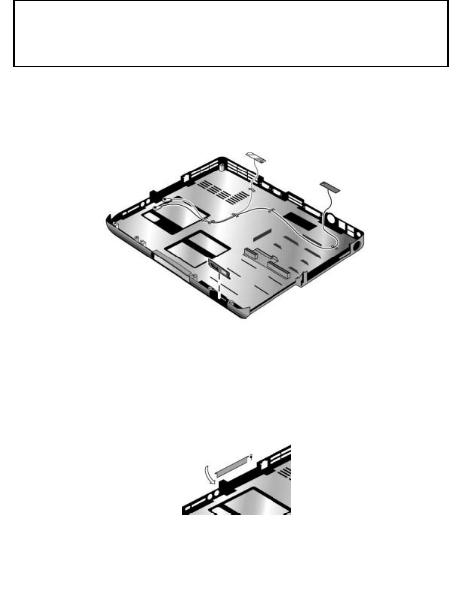
2-60 Removal and Replacement Service Manual
Replacing the Left and Right Antennas
If you need to remove or replace an antenna, see the figure below.
CAUTION: Handle the connector ends of the antennas carefully. Failure to do so could degrade
notebook performance.
Handle the antenna routing metal tabs in the bottom case carefully. These tabs can be easily
broken.
1. Carefully remove both antennas from the old bottom case.
2. Route both antenna cables through the new bottom case as shown below. Make sure you leave enough
room at the cable connector end to connect to the Mini PCI card.
Figure 2-36. Replacing the Antennas
Replacing a PCMCIA Door
If you need to remove or replace a PCMCIA door, see the figure below.
Figure 2-37. Removing a PCMCIA Door

Service Manual Removal and Replacement 2-61
Repairing the BIOS IC
(Authorized Service Providers Only)
The notebook’s BIOS IC cannot be replaced separately. If it is defective, you must replace the
motherboard. In some cases, however, you might be able to reprogram a malfunctioning BIOS IC
using either e-DiagTools for Windows, a BIOS floppy disk, or a Crisis Recovery floppy disk.
If the notebook will boot sufficiently, use e-DiagTools for Windows or a BIOS floppy disk to reprogram
the BIOS IC. If you cannot boot the notebook adequately, use a Crisis Recovery floppy disk. See below for
instructions for all 3 methods.
Using e-DiagTools for Windows
CAUTION: The BIOS update completely replaces the previous BIOS, so follow these directions
exactly or you might damage the notebook. The BIOS update also resets the configurations in
the BIOS Setup utility—except for BIOS passwords—so record these before performing the
update.
Update the notebook’s BIOS as follows:
1. In Windows, exit any programs that are running.
2. Undock the notebook if it is docked, and remove any PCMCIA cards from it.
3. Connect the AC adapter to the notebook.
4. Connect any cables or equipment needed to connect to the Internet.
5. Select Start > Programs (or All Programs) > Hewlett-Packard > Notebook > HP e-DiagTools >
e-DiagTools for Windows.
6. Select Update, > Download New > OK. Follow the instructions that appear. Once the update process
begins, do not interrupt it.
7. The first time you make an Internet connection from this program on a particular unit, select Change
Settings in the Connect window to define your connection settings.
8. When the process completes, press the power button to reset the notebook.
BIOS updates are available from the HP Business Support Web site http://www.hp.com/go/bizsupport.
Installation utilities and instructions for creating a BIOS floppy disk are provided with the updates.
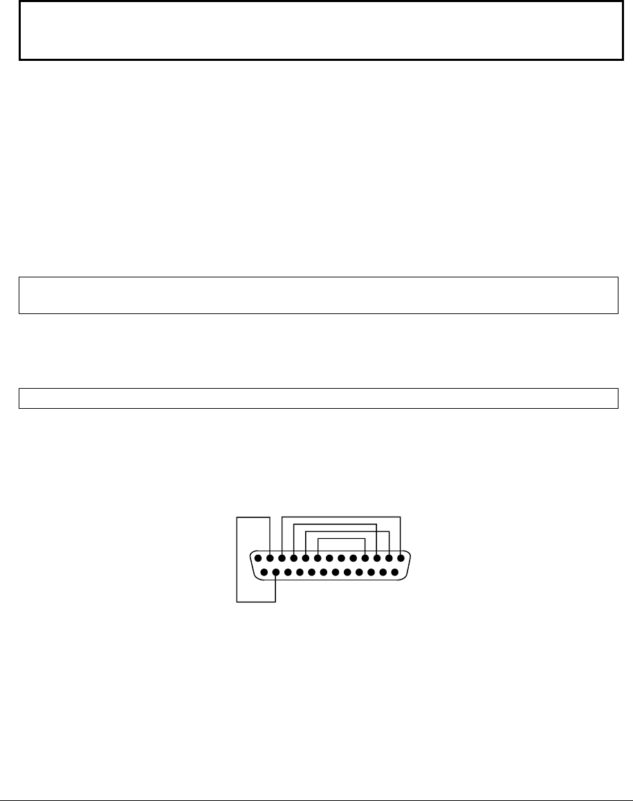
2-62 Removal and Replacement Service Manual
Using a BIOS Floppy Disk
If you do not have a BIOS floppy disk, download the package from the Partnership Web site (see page vii)
under Product Support Information in the Service and Support Library. Follow the instructions for creating
the BIOS floppy disk.
CAUTION: Make sure to use the correct BIOS floppy disk for the notebook model you are
repairing. The program does not verify the notebook model, so you could accidentally install the
wrong BIOS.
1. Insert the BIOS floppy disk in the floppy disk drive.
2. Turn on the notebook and allow it to boot from the BIOS floppy disk.
If the notebook does not turn on at all, do the following to boot from the BIOS floppy disk:
a. Unplug the AC adapter.
b. Press and hold Fn+B.
c. Plug in the AC adapter.
d. Release
Fn+B.
NOTE: If the notebook will not boot from the BIOS floppy disk, try plugging the boot-block jumper into
the notebook’s parallel port. See the wiring diagram below.
3. The display goes blank for a minute or more while the BIOS is reprogrammed.
NOTE: If you plugged in a boot block jumper, unplug it before the notebook automatically reboots.
4. After the BIOS reprograms itself, check the BIOS version to make sure it is the latest version.
If necessary, download the latest BIOS version and reprogram the BIOS IC.
14
1
25
13
Figure 2-38. Boot-Block Jumper

Service Manual Removal and Replacement 2-63
Removing Other Components
(Authorized Service Providers Only)
Required Equipment
• 0 and 1 Phillips screwdrivers
• Small flat-blade screwdriver
Removal Procedure
1. Unplug the AC adapter, if present, and then remove the battery.
2. Remove the assemblies, and then follow the additional steps listed in the table below.
Table 2-5. Removing Components
Component Removal Procedure Additional Steps
Battery, CMOS Keyboard cover(page 2-13)
Speaker (page 2-15)
Keyboard (page 2-16)
Switchboard PCA(page 2-19)
CD/DVD (page 2-20
Display (page 2-23)
Top case (page 2-26)
Floppy (page 2-32)
Heat sink (page 2-40)
Motherboard (page 2-50)
Reassembly Notes: After replacing the CMOS
battery, set the correct time and date using the
BIOS Setup utility or Date/Time in the Control
Panel.
Case, bottom See page 2-3
Case, top See page 2-3
CD/DVD drive See page 2-3
CPU module See page 2-44
Display assembly See page 2-23.
Doors, PCMCIA Keyboard cover(page 2-13)
Speaker (page 2-15)
Keyboard (page 2-16)
Switchboard PCA(page 2-19)
CD/DVD (page 2-20
Display (page 2-23)
Top case (page 2-26)
Heat sink (page 2-40)
Floppy (page 2-32)
Motherboard (page 2-50)
See page 2-3
Floppy drive See page 2-32

2-64 Removal and Replacement Service Manual
Component Removal Procedure Additional Steps
Guide, HDD Keyboard cover(page 2-13)
Speaker (page 2-15)
Keyboard (page 2-16)
Switchboard PCA(page 2-19)
CD/DVD (page 2-20
Display (page 2-23)
Top case (page 2-26
When replacing the HDD guide, make sure you
only replace the 2 right screws. Do not replace
the 2 left screws.
Heat sink (with fan) See page page 2-32
Keyboard See page 2-3
Panel, wireless Keyboard cover(page 2-13)
Speaker (page 2-15)
Keyboard (page 2-16)
Switchboard PCA(page 2-19)
CD/DVD (page 2-20
Display (page 2-23)
Top case (page 2-26)
Press the tabs on both sides of the panel, and
then lift it from the bottom case.
PCA, I/R See page 2-36
PCA, left and right
antennas (wireless
models only)
Keyboard cover(page 2-13)
Speaker (page 2-15)
Keyboard (page 2-16)
Switchboard PCA(page 2-19)
CD/DVD (page 2-20
Display (page 2-23)
Top case (page 2-26)
Floppy (page 2-32)
Heat sink (page 2-40)
Motherboard (page 2-50)
Bottom case (page 2-59)
Disconnect the front antenna PCA cables from
the Mini PCI card (page 2-7).
Be careful not to bend the metal tabs on the
bottom case when removing or replacing either of
the 2 antenna PCAs.
PCA, motherboard See page 2-50
PCA, switchboard See page 2-3
Socket, PCMCIA Keyboard cover(page 2-13)
Keyboard (page 2-16)
CD/DVD (page 2-20)
Display (page 2-23)
Top case (page 2-26)
Floppy (page 2-32)
Heat sink (page 2-40)
Motherboard (page 2-50)
Remove the 2 screws attaching the socket to the
motherboard.
Unplug the PCMCIA socket from the
motherboard.
Speaker assembly See page 2-3.

Service Manual Troubleshooting and Diagnostics 3-1
3
Troubleshooting and Diagnostics
This chapter includes troubleshooting and diagnostic information for testing the functionality of the
notebook, and for identifying faulty components:
• ASP support information
• Troubleshooting information
! Checking for customer abuse (page 3-4)
! Troubleshooting the problem (page 3-5)
! Verifying the repair (page 3-6)
! Suggestions for troubleshooting (page 3-7)
• Diagnostic tools
! e-Diagtools diagnostic program (page 3-18)
! Power-on self-test (page 3-20)
! Sycard PCCtest 450/460 PC card (page 3-26)
! Windows Management Instrumentation (page 3-27)
! BIOS Setup utility (page 3-27)

3-2 Troubleshooting and Diagnostics Service Manual
Support by Authorized Service Providers
In the U.S., support of notebook computers by Authorized Service Providers (ASPs) is a purchasable
option. Standard predefined models and standard special models do not include ASP support. The sales
force has the option of creating models with ASP support using the specials process.
The serial number label on the bottom of the notebook indicates the ASP support status for that model. See
the following table.
Table 3-1. ASP Support Options
Serial Number Label ASP Support Status
“NoASP” No reimbursement to ASP for parts or labor. However the ASP is authorized to repair the
notebook, and reimbursement can be negotiated directly with the customer.
“ASP” Parts and labor will be reimbursed to the ASP.
In other countries, ASP support is standard in most situations but you should check the marking on the serial
number label to verify the ASP support status for that model.
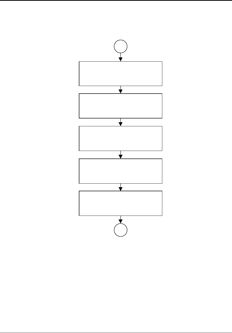
Service Manual Troubleshooting and Diagnostics 3-3
Troubleshooting
The suggestions in this section can help isolate and repair the cause of a problem. To ensure quality repair,
follow the basic troubleshooting steps shown below.
Check the customer’s description
of the problem and any supporting
information.
Try to duplicate the customer’s
problem.
Troubleshoot the problem using:
- Diagnostic tools.
- Troubleshooting suggestions.
Verify the repair by testing the
functionality of the complete unit.
Check for customer abuse.
Figure 3-1. Basic Troubleshooting Steps

3-4 Troubleshooting and Diagnostics Service Manual
Checking for Customer Abuse
Some notebooks might appear to have been damaged by customer abuse. Use these guidelines to help
determine if this is the case:
• If the shipping box is seriously damaged, customer abuse cannot be declared.
• If the damage could have a cause other than customer abuse, customer abuse cannot be declared.
• If the notebook shows any of the following, customer abuse is declared:
! Missing parts
! Broken plastic parts
! Parts not original to the notebook
! Damaged or missing keys on the keyboard
Table 3-3 lists additional criteria for determining customer abuse to specific parts of the notebook.
NOTE: Parts damaged by customer abuse are not covered by the warranty.

Service Manual Troubleshooting and Diagnostics 3-5
Troubleshooting the Problem
Record pertinent information about the notebook:
• Model and serial number
• Operating system and version
• Software version (stored in hidden fileC:\version.inf)
• BIOS version
• Accessories and peripherals used
Analyze the problem:
• Observe Symptoms. Using the customer’s information, try to duplicate the problem. Determine how
the problem differs from proper behavior. Also, note the functions that do work properly.
• Separate Problems. If there are multiple symptoms, separate them into distinct problems.
• Consider Causes. Keep in mind possible causes for each problem. Use the diagnostic tools and
troubleshooting suggestions to help find possible causes.
! The e-Diagtools diagnostic program tests most of the notebook components using
automatic and interactive tests, and is your primary troubleshooting tool. Other tools
include the
power-on self-test, WMI/Toptools (if installed), the BIOS Setup utility, and the Sycard
PCCtest. Table 3-2 on page 3-7 shows how you can use these tools to isolate the cause of
the notebook’s problem.
! The troubleshooting suggestions on page 3-8 include general suggestions for repairing
notebooks that show specific failure symptoms.
Swapping modules that might be defective with others known to be good is generally an ideal way to find
the module responsible for the problem. A failure symptom is rarely caused by more than one module, so
you will not usually need to replace more than one to correct a particular failure.
After you replace a module, the notebook will normally be in a confused state and lock up when you apply
power. If this happens, press the reset button: this turns the notebook off, so that you can restart it in a
known state.

3-6 Troubleshooting and Diagnostics Service Manual
Verifying the Repair
Before returning the repaired notebook to the customer, verify the repair by running the following tests:
• e-Diagtools Basic Diagnostic Test. Run the basic test of the e-Diagtools diagnostic program (page
3-18).
–and–
• Function Tests. Run tests that check the repaired function, such as those in e-Diagtools
(page 3-18).
–and–
• Failed Tests. Run any other tests that failed during troubleshooting.
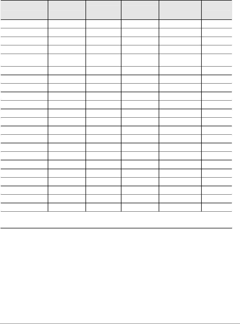
Service Manual Troubleshooting and Diagnostics 3-7
Suggestions for Troubleshooting
Table 3-2. Scope of Diagnostic Tools
Function e-Diagtools
Power-On
Self-Test
Sycard
PCCtest 450
WMI/
Toptools
(if installed) BIOS Setup
Bootup Tests Describes Configures
Processor Tests Describes
Memory Tests Tests Describes Describes
Fan Tests
Batteries Tests (CMOS
battery only)
Describes
Display Tests Describes Configures
Hard disk Tests Tests Describes Configures
Floppy drive Tests* Tests Describes Configures
Keyboard Tests Tests Describes
Audio Tests
Serial Tests* Describes Configures
Parallel Tests Describes Configures
LAN Tests Describes Configures
Modem Configures
Wireless Configures
Infrared Describes Configures
PS/2 port Tests† Configures
USB Describes Configures
Port replicator
PCMCIA Tests Tests Describes
IEEE 1394 Tests
AC adapter Status
*Test might be available only on certain units.
†Use an external keyboard to exercise the port. Run the external 101-key test.
If you cannot isolate the cause of a problem using the above diagnostic tools, use the suggestions in the
following table to help find the problem.

3-8 Troubleshooting and Diagnostics Service Manual
Table 3-3. Troubleshooting Suggestions
Symptom Call Center: Suggestions
Repair Center:
Likely Causes
Repair Center:
Comments
To help determine likely causes of a problem, determine which replaceable modules are involved in the system function and what
roles they play. See the figure on page 1-24 and the table on page 1-25.
Startup
Does not boot on
AC or battery
Check power source.
Press and hold power button to turn
notebook off, and then press power
button to turn notebook on.
Unplug the AC adapter, remove the
battery and any PC cards, press the
reset button to turn notebook off, and
then reconnect power and try again.
Do not use touch pad while booting
or resuming.
Remove all but one SDRAM module
and try again. Reinsert any other
SDRAM module and try again.
AC adapter
SDRAM module.
CPU module
Switchboard PCA
Motherboard
Display assembly
Hard drive
Check AC adapter.
Remove all but one
SDRAM module and try
again.
If the power status light
does not turn on,
reprogram the BIOS, and
replace the top case,
replace the motherboard.
If power status light turns
on but display remains
off, try external monitor. If
monitor shows
successful boot, replace
display assembly.
If monitor shows activity
but BIOS does not
complete, replace display
assembly. If monitor is
blank, replace
switchboard PCA,
replace motherboard.
If power status light and
display turn on, BIOS
completes, but OS does
not start from hard disk
or floppy drive, replace
CPU module, replace
motherboard. If OS starts
from floppy drive, reload
hard drive, replace hard
drive.
Beeps once, spins
hard disk, repeats,
but does not boot
Make sure at least one SDRAM
module is installed.
SDRAM module
Does not boot on battery,
but boots on AC
Make sure battery is properly
installed and fully charged. Check
battery level on battery LEDs.
Check battery contacts. If available,
try another battery.
Battery or contacts
Motherboard
Does not boot from
floppy drive
Make sure floppy disk is bootable.
Use BIOS Setup to check default
boot order.
Floppy disk or floppy drive
Motherboard.
Make sure floppy drive is
installed and connected
correctly.
Does not boot from CD in
CD/DVD drive
Make sure CD is bootable.
Use BIOS Setup to check default
boot order.
Restart notebook.
CD/DVD drive
Motherboard
Make sure CD/DVD is
installed and connected
correctly.
Sluggish startup or
shutdown
Use Tools tab in disk’s Properties
sheet to check hard disk. Use Disk
Defragmenter to optimize hard disk.
Delete temporary and unneeded
files.
Hard drive

Service Manual Troubleshooting and Diagnostics 3-9
Symptom Call Center: Suggestions
Repair Center:
Likely Causes
Repair Center:
Comments
Error message such as
“Invalid system disk” or
“Auto IDE error”
Check for disk in floppy drive.
Check boot order in BIOS Setup.
Remove and reinstall hard drive.
Hard drive contacts
Hard drive
If notebook boots from
floppy drive, check for
corrupt files on hard
drive, use Recovery CDs
to reinstall factory
software onto hard drive,
replace hard drive.
Password forgotten Verify proper ownership, and then
follow removal procedure with owner
and record appropriate data—see
page 5-2.
User must call Technical
Support and provide
proof of ownership.
Password removal is
restricted to certain sites.
See page 5-2.
Power
No power Make sure charged battery is
installed or AC adapter connected.
Try another battery or AC adapter if
available.
AC adapter
Battery
Motherboard
Notebook has short
operating time when on
battery
Turn down display brightness.
Check timeout settings in Power in
Control Panel.
Check power management settings
in BIOS Setup. Try default settings.
Battery gauge might need calibration.
Run HP Battery Optimizer from
Start menu.
Certain applications can cause
excess CPU and power usage.
(User can get Intel Power Monitor
from http://www.intel.com/ and monitor
CPU load.)
When playing DVD movies on battery
power, use Power Options in Control
Panel to select Portable/Laptop
power scheme.
When using applications with
automatic save feature (such as MS
Word), extend save time or disable to
reduce hard disk access and power
usage.
PCMCIA card use can affect battery
life. Some PCMCIA cards draw
power even while not in use.
Heavy modem use can affect battery
operating time.
Battery
Motherboard
Battery capacity often
decreases after a year
or more.
Turns off immediately
after turning on
Battery may be extremely low. Plug
in AC adapter or insert charged
battery.
Battery
Does not run on battery;
empty battery indication
Check battery and contacts. Try
another battery if available.
Battery or contacts
Motherboard
Beeps repeatedly Notebook beeps repeatedly when
battery is low. Connect AC adapter
or replace battery.
Battery

3-10 Troubleshooting and Diagnostics Service Manual
Symptom Call Center: Suggestions
Repair Center:
Likely Causes
Repair Center:
Comments
Battery does not charge Make sure AC adapter has correct
power rating.
Make sure AC adapter is connected
properly and battery installed
properly.
Check battery contacts. If available,
try another battery and AC adapter.
Move notebook away from any
nearby heat source. Unplug AC
adapter and allow battery to cool.
Check for blocked air vents.
Battery or contacts
AC adapter
Motherboard
Heat sink
Check battery and
AC adapter
Check heat sink
AC adapter does not
power notebook
Try another AC adapter, if available. AC adapter
Motherboard
AC adapter cannot be
repaired, and must
be replaced.
Battery indicator is
inaccurate
Time Remaining is an estimate
based on notebook’s power use at
that moment. It, therefore, depends
on current task and assumes power
will be used at that rate until battery
runs out. So if notebook is currently
using good deal of power (such as
when reading CD or DVD), Time
Remaining likely shows less time
than actually remains.
Standby/resume
General problems Close all applications before entering
(or allowing notebook to enter)
Standby or Hibernation mode.
If problem appears after installing
new software (including drivers),
uninstall that software. Contact
software vendor for additional
support.
Notebook resumes slowly
from Standby mode
Notebook can take a minute or
longer to resume if network card is
installed. Blinking cursor appears
while system is loading and checking
hardware and network connections.
When hardware is reinitialized,
Windows desktop appears.
Does not suspend to
Standby mode as
expected
Notebook won’t suspend
if connection to another computer is
active.
If notebook is busy, it normally
finishes current operation before
suspending.
Does not automatically
enter Hibernation mode as
expected
Make sure hibernate support is
enabled in Power in Control Panel.
Also, make sure Hibernate timeouts
(Power Schemes tab) for AC and
battery power are not set to Never.

Service Manual Troubleshooting and Diagnostics 3-11
Symptom Call Center: Suggestions
Repair Center:
Likely Causes
Repair Center:
Comments
Display
Dark display, no light Make sure notebook is turned on and
warmed up.
Check power supply.
Make sure SDRAM modules are
installed properly.
Adjust display brightness.
Press Fn+F5 several times.
Try external monitor.
Display cable connection
SDRAM modules
CPU module
Display assembly
Motherboard
Check cable
connections.
Replace SDRAM
modules.
Make sure CPU module
is installed properly,
replace CPU module.
Check display cable
connections, replace
display assembly.
If external monitor
displays no image,
replace motherboard.
White display Adjust display brightness. Display assembly
Switchboard PCA
Erratic display Display cable connection
Switchboard PCA
Display assembly
Motherboard
Check display cable
connection.
Bright or missing pixels or
lines.
See quality statement on page 5-3. Display cable connection
Display assembly
Check display cable
connection.
See quality statement on
page 5-3.
Punctured display Declared to be caused by
customer abuse.
Vertical crack near center
of display.
Usually caused by closing
display with pencil-sized
object on keyboard
Declared to be caused by
customer abuse.
Scratched display glass Declared to be caused by
customer abuse.
Local area of dark or light
discoloration visible when
display is on
Caused by excessive
pressure applied to area on
screen
Declared to be caused by
customer abuse.
External display does not
work
Check connections.
Press Fn+F5 several times.
Try display on another computer.
External display
Motherboard
Hard disk
Hard disk never spins Check power source.
Remove and reinstall hard drive.
Check connector.
Hard drive or connector
Motherboard
If drive case is damaged,
drive may not operate
properly.
Hard disk makes clunking
or scratching noise
Back up disk immediately.
Was notebook or drive dropped?
Hard drive Check notebook and
drive for evidence of
customer abuse.
Hard disk makes buzzing
or whining noise
Back up disk immediately.
Check hard disk installation.
Check for alternate noise sources,
such as PCMCIA drive or fan.
Depends on noise source

3-12 Troubleshooting and Diagnostics Service Manual
Symptom Call Center: Suggestions
Repair Center:
Likely Causes
Repair Center:
Comments
Files corrupted Run virus scan program.
Check hard disk using Tools tab in
disk’s Properties sheet.
Test hard disk drive with e-Diagtools
diagnostics.
Back up files if possible, then use
Recovery CDs to reformat hard disk
and reinstall factory software.
Disk capacity less than
normal
Check hard disk using Tools tab in
disk’s Properties sheet.
Check partitions using Control Panel,
Administrative Tools, and Computer
Management under Storage.
Use Recovery CDs to reformat hard
disk and reinstall factory software.
Hard drive
Disk’s reported capacity is
less than actual size
Hard disk allocates approximately 20
MB to diagnostic software. This
space is unavailable for other uses,
and not included in hard disk
capacity reported by Windows.
Floppy drive
General problems No response from floppy drive. Floppy drive
Motherboard
Make sure floppy drive is
installed and connected
correctly.
CD/DVD drive
Particular CD or DVD not
playing properly
Check disk for proper insertion, dirt,
or damage. Clean with soft cloth or
replace as needed.
If CD was created on CD-RW drive,
try using HP certified media. Read
and write quality can vary for other
media.
Cannot read any CD or
DVD
Restart notebook.
Make sure CD/DVD drive is installed
properly.
CD/DVD drive
DVD movie stops playing DVD may be double-sided.
Movie may be paused.
Press Play button.
Region Code error DVDs contain embedded regional
codes that prevent them from playing
outside region in which they are sold.
This error occurs when trying to play
DVD intended for different region.
NOTE: Most DVD drives allow region
code to be changed only a limited
number of times (usually no more
than four). When this limit is reached,
last change is hard-coded on DVD
drive, and is permanent. Refer to
DVD player software help for details.
HP warranty does not
cover expense of
correcting this situation.

Service Manual Troubleshooting and Diagnostics 3-13
Symptom Call Center: Suggestions
Repair Center:
Likely Causes
Repair Center:
Comments
System Error: Unable to
read drive” message
Make sure disk is clean, undamaged,
and inserted correctly. Clean with
soft cloth or replace as needed.
Wait 5 to 10 seconds after closing
tray before pressing Play.
Restart notebook.
CD/DVD drive
Motherboard
Make sure CD/DVD drive
is installed properly.
No DVD or CD-RW
software on notebook
If software was removed, use the
Recovery CDs to reinstall factory
software.
All DVD play is erratic Some DVDs include software called
“PC Friendly”. This software
can cause errors or erratic play. If
needed, uninstall PC Friendly and
restart notebook.
Keyboard
Some or all keys do not
work properly
Check settings in Control Panel. Keyboard
Motherboard
Try reinserting ribbon
cable in connector on
motherboard.
Embedded
numeric keypad
does not work
Press Fn+F8 to activate numeric
keypad, and Lock key to turn on
number lock.
Avoid touching touch pad while
booting or resuming.
KeyboarD
Motherboard
PS/2 keyboard and mouse
with Y-adapter do not
work
Check devices separately. Y-adapter
PS/2 device
Motherboard
Touch pad
General problems Reset notebook (see page 1-17).
Check settings in Control Panel.
Make sure touch pad is enabled in
Mouse Properties.
By default, touch pad is disabled if
external PS/2 mouse is connected,
Use BIOS Setup to check settings.
Avoid touching touch pad while
booting or resuming.
Top case
Motherboard
Special touch pad
features not working
In Mouse Properties, select
Synaptics PS/2 TouchPad driver.
(Driver is installed from
\hp\drivers\TouchPad.)
Top case
Motherboard
Select button does
not work
Top case
Motherboard
Memory
Out of memory error Make sure C drive has adequate free
space. Delete temporary and
unneeded files.
Use memory troubleshooter in
Windows Help.
Not all third-party memory cards
have been tested for use with
notebook.
SDRAM module

3-14 Troubleshooting and Diagnostics Service Manual
Symptom Call Center: Suggestions
Repair Center:
Likely Causes
Repair Center:
Comments
Notebook does not boot
after adding SDRAM
Use only DDR-266 SDRAM modules. SDRAM module
Audio
No sound audible Increase sound volume.
Check whether sound is enabled
(mute button and software controls).
Check for sound resource conflicts in
Device Manager.
Test audio with e-Diagtools
diagnostics.
Top case
Speaker assembly
Switchboard PCA
Motherboard
Check operation using
headphones or
external speakers
(switchboard PCA).
Make sure speaker
assembly cable is
connected.
Sound does not record Use an external microphone (internal
microphone normally not included).
Check software controls.
Test audio with e-Diagtools
diagnostics.
Switchboard PCA
Motherboard
Serial/Parallel/USB
General problems Check connections.
Restart notebook.
Use troubleshooters in Windows
Help.
Check settings in Control Panel.
Check port settings in Device
Manager.
Test ports with e-Diagtools
diagnostics.
For USB: contact device vendor and
HP Notebook Web site (see page vii)
for latest USB drivers.
For USB: if the device is powered by
the USB port, try the other port.
Motherboard
Modem
General problems Check settings in Control Panel.
Open hardware Device Manager.
If modem is disabled, try to enable.
If modem has a conflict, try disabling
another device.
Use analog telephone line (2, 3, or
4 wires), not PBX or digital line. In a
hotel, ask for data line.
Try disabling error correction and
data compression.
Test modem with e-Diagtools
diagnostics.
Motherboard

Service Manual Troubleshooting and Diagnostics 3-15
Symptom Call Center: Suggestions
Repair Center:
Likely Causes
Repair Center:
Comments
LAN/network
General problems Check cables and connections.
Try connecting notebook to another
network station (if applicable). If
green light next to LAN port does not
light, LAN cable may not be
connected to network or network
may be down.
Use networking troubleshooter in
Windows Help.
Check settings in Control Panel.
Make sure LAN cable is Category 3,
4, or 5 for 10Base-T operation,
or Category 5 for 100Base-TX
operation. Maximum cable length is
100 meters (330 feet).
Test LAN with e-Diagtools
diagnostics.
Motherboard
Infrared
General problems Infrared is disabled and no drivers
installed as shipped. (Drivers are
included.)
Make sure line between infrared
ports is not blocked, ports face each
other squarely and are no more than
1 meter apart. Sunlight, heat from
nearby equipment, or other sources
of infrared radiation can cause
transmission errors.
Open Hardware Device Manager. Try
to enable the infrared port.
Remove any PC cards from
notebook (possible IRQ conflict).
For fast-IrDA, check for DMA conflict
with ECP parallel port.
Motherboard
Wireless
General problems Check TCP/IP setup in Control
Panel.
Check SSID, channel, and
encryption settings.
Mini PCI card
Antenna PCAs
Motherboard
Make sure all cables are
properly connected to
Mini PCI card and
motherboard. Check for
damaged coaxial cables
or connectors.
One-Touch button
problems
Buttons not working
properly
Make sure correct applications are
associated with buttons in One-
Touch tab of Keyboard in Control
Panel.
Keyboard cover
Switchboard PCA
Motherboard
On-screen display does
not appear when button is
pressed
Make sure Onscreen Display is
enabled in One-Touch tab of
Keyboard in Control Panel.
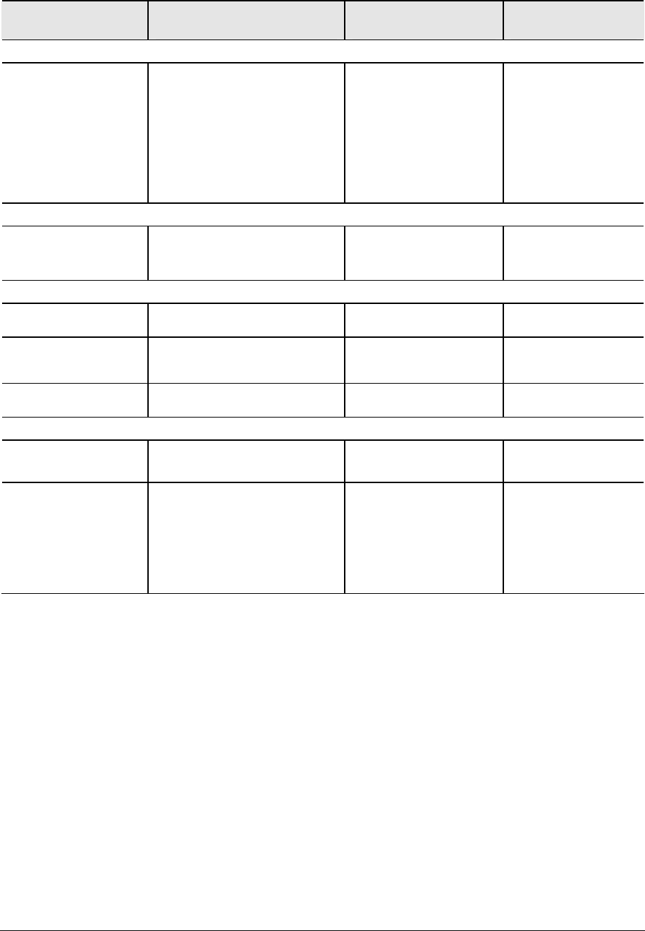
3-16 Troubleshooting and Diagnostics Service Manual
Symptom Call Center: Suggestions
Repair Center:
Likely Causes
Repair Center:
Comments
PCMCIA
General problems Restart notebook.
Try card in another computer.
If card requires an IRQ, make sure
one is available.
In Device Manager, refresh device
list and check for conflicts.
Download current drivers from card
manufacturer’s Web site
PCMCIA socket
Motherboard
Using a flashlight, look
for bent pins inside the
PCMCIA socket.
For model XE4500, if
only one slot is affected,
replace PCMCIA socket.
If both slots are affected,
replace motherboard.
AC adapter
Does not power noteboo Make sure AC adapter has correct
power rating.
Try another AC adapter, if available.
AC adapter
Motherboard
AC adapter cannot be
repaired and must be
replaced.
Motherboard
Evidence of spilled liquid Declared to be caused by
customer abuse.
Bent or broken
connectors, or burnt
component
Declared to be caused by
customer abuse.
Motherboard cracked. Declared to be caused by
customer abuse.
Miscellaneous
Clock loses time Plug in AC adapter for 24 hours to
charge CMOS battery.
CMOS battery
Motherboard
Charge CMOS battery.
Notebook gets
abnormally hot
Always set notebook on a flat
surface, so air can flow freely around
and underneath it.
Make sure air vents are not blocked.
Games and other programs that
drive CPU usage toward 100% can
contribute.
Heat sink Check heat sink for
damage or proper fan
operation.
Check thermal contact
between CPU and heat
sink. Replace thermal
pad if needed.
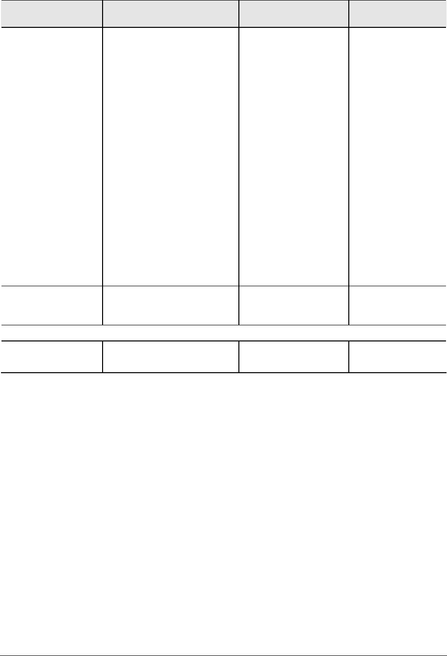
Service Manual Troubleshooting and Diagnostics 3-17
Symptom Call Center: Suggestions
Repair Center:
Likely Causes
Repair Center:
Comments
Notebook pauses or runs
sluggishly
May be normal Windows behavior
(background processing can affect
response time).
Certain operations (such as virus
scanning or file browsers) can affect
performance.
Press ctrl+alt+del to see if an
application is not responding.
Restart notebook.
If hard disk has spun down to
conserve power, it can take several
seconds to spin up (you can hear
this). Use Control Panel to modify
hard disk power settings.
Check for overheating—see previous
symptom.
If notebook’s hard drive frequently
runs (as indicated by hard drive light
on front of notebook) while notebook
appears to be paused or running
slowly, consider installing additional
SDRAM.
Make sure hard drive has adequate
free space. Delete temporary and
unneeded files.
CPU module
Motherboard
If notebook slows after
period of continuous
activity, check heat
sink—see previous
symptom.
Notebook still on but stops
responding
Press ctrl+alt+del and end any
application not responding.
Reset notebook (see page 1-17).
Accessories
Port replicator problems Check notebook’s power supply.
Check settings in BIOS Setup.
Port replicator
Motherboard
Port replicator is not
repairable, and must be
exchanged.

3-18 Troubleshooting and Diagnostics Service Manual
Diagnostic Tools
This section describes the following diagnostic tools you can use for troubleshooting and repairing the
notebook:
• Notebook e-Diagtools diagnostic program (below)
• Power-on self-test (page 3-20)
• Sycard PCCtest 450 PC card (page 3-26)
• Windows Management Instrumentation (page 3-27)
• BIOS Setup utility (page 3-27)
e-Diagtools Diagnostic Program
The hardware diagnostic programs provide two levels of testing:
• User-level testing using a basic hardware test.
• Advanced testing using individual hardware tests.
The tests are designed to run after the system reboots, so that the notebook will be in a predictable state
during the tests. The tests are non-destructive, and are intended to preserve the state of the notebook. The
notebook reboots when you exit the program so drivers can be loaded.
Updating e-Diagtools
You can download the latest version of e-Diagtools using e-Diagtools for Windows.
Running e-Diagtools
The following procedure describes how to run e-Diagtools. The individual steps might differ slightly for
different versions of e-Diagtools.
1. Select Start > Turn Off Computer (Shut Down) or Restart.
2. When the HP logo appears, press F10 to start the diagnostic test.
The first time you run the program, you are prompted to select the language for the program.
3. When the menu appears, press F2 to run e-Diagtools.
4. When the Configuration Description appears, check the list of detected hardware.
5. Run the basic test. Press F2 to start the basic hardware test. The results appear when the test is
complete.
6. If you intend to exit without running the advanced tests, press F4 to view the Support Ticket.
Press F3 to exit e-Diagtools.
7. Optional: run the advanced tests. Press F2 to open the advanced test screen.
8. Use the arrow keys and enter to select the test you want to run. Tests are listed only for detected
hardware.
9. Press F2 to run the selected tests and add the results to the Support Ticket.

Service Manual Troubleshooting and Diagnostics 3-19
10. After each run, press F2 to return to the advanced test screen, or press F4 to view the Support Ticket.
11. Exit. Press F3 and then any key to exit and reboot.
12. Optional: open the Support Ticket. In Windows, select Start > All Programs (or Programs) >
Hewlett-Packard > Notebook > HP e-Diagtools > e-Diagtools for Windows.
13. Select View to display the Support Ticket.
14. To add information about your problem, select Comments, type the information, and then select OK.
To save or print the Support Ticket, select Save As or Print.
To e-mail the Support Ticket to your support agent, select e-Mail. The first time you make an e-mail
connection from this program, select Change Settings in the Connect window and enter the settings
recommended by your support agent.
e-Diagtools for Windows can also update the version of e-Diagtools on your notebook’s hard disk.
In e-Diagtools for Windows, use the e-Diagtools menu.
If you have trouble running e-Diagtools diagnostics from the hard disk, you can also run it from the
Recovery CD or DVD. Boot from the CD or DVD and select the diagnostics option.
Interpreting the Results
The e-Diagtools diagnostic program returns test groups, error codes, and suggestions for repair and/or
follow-up actions. The basic hardware test shows a recommended replacement part.
To help interpret the results of the e-Diagtools tests, refer to the following:
• e-Diagtools Support Ticket on page 3-19.
• Replaceable Module Diagram on page 1-24
• Functional Structure Description on page 1-25
This combined information should enable you to determine which of the notebook’s components require
service.
3-20 Troubleshooting and Diagnostics Service Manual
Power-On Self-Test
NOTE: If Quiet Boot is enabled in BIOS Setup (the default setting), press esc during boot to see POST
(Power-On Self-Test) messages.
When the notebook boots, its system BIOS runs a series of initialization routines and diagnostic tests called
POST. The BIOS will not boot the notebook’s operating system if the system memory, CPU, DMA, or
interrupt controller fails the POST diagnostic tests. POST indicates progress by a sequence of codes; if an
error occurs, the BIOS displays a message and/or issues a beep code.
Note that not all POST messages indicate a failure in the notebook—some messages are for information
only. You should not necessarily interpret the failure of one or more POST tests as a hardware, software, or
firmware failure. If POST displays an error message or issues a beep code indicating an error, confirm the
problem using other diagnostic tools.
First, confirm the failure by performing a “clean” boot, as described below. Note that if the notebook fails to
restart with a clean boot, it requires repair.
1. Remove all accessories, including SDRAM modules, port replicator, PC cards, printer, external
monitor, pointing device, and keyboard.
2. Provide “clean” AC power—no auto adapter or unusual AC adapter configuration.
3. Press the reset button to return the notebook to a known state.
4. Press the power button to start the notebook.
If the BIOS detects a terminal error condition, it halts POST after issuing a beep code and/or displaying a
message (see the following table). The beep code indicates the POST routine in which the terminal error
occurred.
Table 3-4. POST Terminal-Error Beep Codes
Beep Codes POST Description
1 One short beep before boot
1-2 Search for option ROMs
1-1-1-3 Verify Real Mode
1-1-1-4 Disable Non-Maskable Interrupt (NMI)
1-1-2-1 Get CPU type
1-1-2-3 Initialize system hardware
1-1-2-4 Disable shadow and execute code from ROM
1-1-3-1 Initialize chipset with initial POST values
1-1-3-2 Set IN POST flag
1-1-3-3 Initialize CPU registers
1-1-3-4 Enable CPU cache
1-1-4-1 Initialize caches to initial POST values
1-1-4-3 Initialize I/O component
1-1-4-4 Initialize local bus IDE
1-2-1-1 Initialize Power Management
1-2-1-2 Load alternate registers with initial POST values
1-2-1-3 Restore CPU control word during warm boot

Service Manual Troubleshooting and Diagnostics 3-21
Beep Codes POST Description
1-2-1-4 Initialize PCI Bus Mastering devices
1-2-2-1 Initialize keyboard controller
1-2-2-3 BIOS ROM checksum
1-2-2-4 Initialize cache before memory Auto size
1-2-3-1 8254 timer initialization
1-2-3-3 8237 DMA controller initialization
1-2-4-1 Reset Programmable Interrupt Controller
1-3-1-1 Test DRAM refresh
1-3-1-3 Test 8742 Keyboard Controller (on motherboard)
1-3-2-1 Set ES segment register to 4 GB
1-3-3-1 Auto size DRAM; or wrong type or no RAM installed
1-3-3-2 Initialize POST Memory Manager
1-3-3-3 Clear 512 KB base RAM
1-3-4-1 RAM failure on address line xxxx
1-3-4-3 RAM failure on data bits xxxx of low byte of memory bus
1-3-4-4 Enable cache before system BIOS shadow
1-4-1-1 RAM failure on data bits xxxx of high byte of memory bus
1-4-1-3 Test CPU bus-clock frequency
1-4-1-4 Initialize Phoenix Dispatch Manager
1-4-2-3 Warm start shut down
1-4-3-1 Shadow system BIOS ROM
1-4-3-3 Auto size cache
1-4-4-1 Advanced configuration of chipset registers
1-4-4-2 Load alternate registers with CMOS values
2-1-1-2 Initialize extended memory for ROMPilot
2-1-1-3 Initialize interrupt vectors
2-1-2-2 POST device initialization
2-1-2-3 Check ROM copyright notice
2-1-2-4 Initialize I20 support
2-1-3-1 Check video configuration against CMOS
2-1-3-2 Initialize PCI bus and devices
2-1-3-3 Initialize all video adapters in system
2-1-3-4 QuietBoot start (optional)
2-1-4-1 Shadow video BIOS ROM
2-1-4-3 Display BIOS copyright notice
2-1-4-4 Initialize MultiBoot
2-2-1-1 Display CPU type and speed
2-2-1-2 Initialize EISA board
2-2-1-3 Test keyboard
2-2-2-1 Set key Select if enabled
2-2-2-2 Enable USB devices
2-2-3-1 Test for unexpected interrupts
2-2-3-2 Initialize POST display service
2-2-3-3 Display prompt "Press F2 to enter SETUP"
2-2-3-4 Disable CPU cache
2-2-4-1 Test RAM between 512 and 640 KB
2-3-1-1 Test extended memory
2-3-1-3 Test extended memory address lines
2-3-2-1 Jump to UserPatch1
2-3-2-3 Configure advanced cache registers

3-22 Troubleshooting and Diagnostics Service Manual
Beep Codes POST Description
2-3-2-4 Initialize Multi Processor APIC
2-3-3-1 Enable external and CPU caches
2-3-3-2 Set up System Management Mode (SMM) area
2-3-3-3 Display external L2 cache size
2-3-3-4 Load custom defaults (optional)
2-3-4-1 Display shadow-area message
2-3-4-3 Display possible high address for UMB recovery
2-4-1-1 Display error messages
2-4-1-3 Check for configuration errors
2-4-2-3 Check for keyboard errors
2-4-4-1 Set up hardware interrupt vectors
2-4-4-2 Initialize Intelligent System Monitoring
2-4-4-3 Initialize coprocessor if present
3-1-1-1 Disable onboard Super I/O ports and IRQs
3-1-1-2 Late POST device initialization
3-1-1-3 Detect and install external RS232 ports
3-1-1-4 Configure non-MCD IDE controllers
3-1-2-1 Detect and install external parallel ports
3-1-2-2 Initialize PC-compatible PnP ISA devices
3-1-2-3 Re-initialize onboard I/O ports
3-1-2-4 Configure Motherboard Configurable Devices (optional)
3-1-3-1 Initialize BIOS Data Area
3-1-3-2 Enable Non-Maskable Interrupts (NMIs)
3-1-3-3 Initialize Extended BIOS Data Area
3-1-3-4 Test and initialize PS/2 mouse
3-1-4-1 Initialize floppy controller
3-1-4-4 Determine number of ATA drives (optional)
3-2-1-1 Initialize hard-disk controllers
3-2-1-2 Initialize local-bus hard-disk controllers
3-2-1-3 Jump to UserPatch2
3-2-1-4 Build MPTABLE for multi-processor boards
3-2-2-2 Install CD-ROM for boot
3-2-2-3 Clear huge ES segment register
3-2-2-4 Fix up Multi Processor table
3-2-3-2 Check for SMART Drive (optional)
3-2-3-3 Shadow option ROMs
3-2-4-1 Set up Power Management
3-2-4-2 Initialize security engine (optional)
3-2-4-3 Enable hardware interrupts
3-2-4-4 Determine number of ATA and SCSI drives
3-3-1-1 Set time of day
3-3-1-3 Check key lock
3-3-2-1 Initialize typematic rate
3-3-3-1 Erase F2 prompt
3-3-3-3 Scan for F2 keystroke
3-3-4-1 Enter SETUP
3-3-4-3 Clear Boot flag
3-4-1-1 Check for errors
3-4-1-2 Inform ROMPilot about the end of POST
3-4-1-3 POST done—prepare to boot OS
3-4-2-2 Terminate QuietBoot (optional)
3-4-2-3 Check password (optional)
3-4-2-4 Initialize ACPI BIOS

Service Manual Troubleshooting and Diagnostics 3-23
Beep Codes POST Description
3-4-3-2 Prepare Boot
3-4-3-3 Initialize SMBIOS
3-4-3-4 Initialize PnP Option ROMs
3-4-4-1 Clear parity checkers
3-4-4-2 Display MultiBoot menu
3-4-4-3 Clear screen (optional)
3-4-4-4 Check virus and backup reminders
4-1-1-1 Try to boot with INT 19
4-1-1-2 Initialize POST Error Manager (PEM)
4-1-1-3 Initialize error logging
4-1-1-4 Initialize error display function
4-1-2-1 Initialize system error handler
4-1-2-2 PnPnd dual CMOS (optional)
4-1-2-3 Initialize note dock (optional)
4-1-2-4 Initialize note dock late
4-1-3-1 Force check (optional)
4-1-3-2 Extended checksum (optional)
4-1-3-3 Redirect Int 15h to enable remote keyboard
4-1-3-4 Redirect Int 13h to Memory Technologies Devices such as ROM, RAM, PCMCIA, and serial disk
4-1-4-1 Redirect Int 10h to enable remote serial video
4-1-4-2 Re-map I/O and memory for PCMCIA
4-1-4-3 Initialize digitizer and display message
4-2-1-3 Unknown interrupt
4-3-1-1 Initialize the chipset
4-3-1-2 Initialize the bridge
4-3-1-3 Initialize the CPU
4-3-1-4 Initialize system timer
4-3-2-1 Initialize system I/O
4-3-2-2 Check force recovery boot
4-3-2-3 Checksum BIOS ROM
4-3-2-4 Go to BIOS
4-3-3-1 Set Huge Segment
4-3-3-2 Initialize Multi Processor
4-3-3-3 Initialize OEM special code
4-3-3-4 Initialize PIC and DMA
4-3-4-1 Initialize Memory type
4-3-4-2 Initialize Memory size
4-3-4-3 Shadow Boot Block
4-3-4-4 System memory test
4-4-1-1 Initialize interrupt vectors
4-4-1-2 Initialize Run Time Clock
4-4-1-3 Initialize video
4-4-1-4 Initialize System Management Manager
4-4-2-1 Output one beep
4-4-2-2 Clear Huge Segment
4-4-2-3 Boot to Mini DOS
4-4-2-4 Boot to Full DOS
1 long,
2 short
Improper video configuration (reprogram EEPROM) or external ROM checksum failure

3-24 Troubleshooting and Diagnostics Service Manual
The following table lists POST messages and explanations for reported problems If the system fails after
you make changes in BIOS Setup, reset the notebook, enter BIOS Setup, and install the defaults or correct
the error.
Table 3-5 POST Messages
Message Description
0200 Failure Fixed Disk Fixed (hard) disk is not working or not configured properly Make sure the hard disk is
installed properly Run BIOS Setup and make sure the hard disk type is correctly identified
0210 Stuck key Stuck key on keyboard
0211 Keyboard error Keyboard is not working
0212 Keyboard Controller
Failed
Keyboard controller failed the test Might require replacing the motherboard (contains the
keyboard controller)
0213 Keyboard locked Unlock key switch Unlock the system to proceed
0220 Monitor type does not
match CMOS—Run SETUP
Monitor type is not correctly identified in BIOS Setup
0230 Shadow RAM Failed at
offset: nnnn
Shadow RAM failed at offset nnnn of the 64k block at which the error was detected
0231 System RAM Failed at
offset: nnnn
System RAM failed at offset nnnn of the 64k block at which the error was detected
0232 Extended RAM Failed at
offset: nnnn
Extended memory is not working or not configured properly at offset nnnn Update to the
latest BIOS version
0250 System battery is dead—
Replace and run SETUP
CMOS clock battery indicator shows that the CMOS battery is dead Connect the AC adapter
for at least 24 hours, and then run BIOS Setup to reconfigure the system
0251 System CMOS checksum
bad—Default configuration
used
System CMOS has been corrupted or modified incorrectly, perhaps by an application that
changes CMOS data In response, the BIOS has installed the default Setup values Use BIOS
Setup to modify these values if needed If the error persists, check the system battery
Connect the AC adapter for at least 24 hours; replace the motherboard
0260 System timer error Timer test failed Replace the motherboard
0270 Real time clock error Real-time clock failed the BIOS test Might require replacing the motherboard
0271 Check date and time
settings
BIOS found the date or time to be out of range, and then reset the real-time clock You might
need to use BIOS Setup to reset the legal date
0280 Previous boot
incomplete—Default
configuration used
Previous POST did not complete successfully POST loads default values and offers to run
BIOS Setup If the failure was caused by incorrect values that are not corrected, the next boot
will likely fail This error is cleared the next time the system is booted
0281 Memory Size found by
POST differed from CMOS
Memory size found by POST differed from that specified in CMOS
02B0 Diskette drive A error Drive A: is present but fails the BIOS POST diskette tests Make sure the drive is defined with
the proper diskette type in BIOS Setup, and that the drive is connected correctly
02B2 Incorrect Drive A type—
run SETUP
Type of floppy drive A: not correctly identified in BIOS Setup
02D0 System cache error—
Cache disabled
RAM cache failed and BIOS disabled the cache May require replacing the motherboard
A disabled cache slows system performance considerably
02F0: CPU ID CPU socket number for Multi-Processor error
02F4: EISA CMOS Not
Writeable
ServerBIOS2 test error: Cannot write to EISA CMOS
02F5: DMA Test Failed ServerBIOS2 test error: Cannot write to extended Direct Memory Access (DMA) registers
02F6: Software NMI Failed ServerBIOS2 test error: Cannot generate software Non-Maskable Interrupt (NMI)

Service Manual Troubleshooting and Diagnostics 3-25
Message Description
02F7: Fail-Safe Timer NMI
Failed
ServerBIOS2 test error: Fail-safe timer takes too long
device Address Conflict Address conflict for the specified device
Allocation Error for: device Run ISA or EISA Configuration Utility to resolve a resource conflict for the specified device
CD ROM Drive CD-ROM drive identified
Entering SETUP Starting BIOS Setup
Failing Bits: nnnn Hex number nnnn is a map of the bits at the RAM address that failed the memory test Each
1 (one) in the map indicates a failed bit See errors 230, 231, or 232 above for offset address
of the failure in System, Extended, or Shadow memory
Fixed Disk n Fixed disk n (0–3) identified
Invalid System Configuration
Data
Problem with NVRAM (CMOS) data
I/O device IRQ conflict I/O device IRQ conflict error
PS/2 Mouse Boot Summary
Screen:
PS/2 mouse installed
nnnn kB Extended RAM
Passed
Where nnnn is the amount of RAM in KB successfully tested
nnnn Cache SRAM Passed Where nnnn is the amount of system cache in KB successfully tested
nnnn KB Shadow RAM Passed Where nnnn is the amount of shadow RAM in KB successfully tested
nnnn KB System RAM Passed Where nnnn is the amount of system RAM in KB successfully tested
Operating system not found
Operating system cannot be located on drive A: or drive C: Enter BIOS Setup and see if the
hard disk and drive A: are properly identified
Parity Check 1 nnnn Parity error found in the system bus BIOS attempts to locate the address and display it on
the screen Parity is a method for checking errors in binary data A parity error indicates that
data has been corrupted
Parity Check 2 nnnn Parity error found in the I/O bus BIOS attempts to locate the address and display it on the
screen
Press <F1> to resume, <F2> to
Setup, <F3> for previous
Displayed after any recoverable error message Press <F1> to start the boot process or <F2>
to enter BIOS Setup and change the settings Press <F3> to display the previous screen
(usually an initialization error of an Option ROM, such as an add-on card) Write down and
follow the information shown on the screen
Press <F2> to enter Setup Optional message displayed during POST
PS/2 Mouse PS/2 mouse identified
System BIOS shadowed System BIOS copied to shadow RAM
UMB upper limit segment
address: nnnn
Displays the address nnnn of the upper limit of Upper Memory Blocks (UMB), indicating
released segments of the BIOS that can be reclaimed by a virtual memory manager
Video BIOS shadowed Video BIOS copied to shadow RAM
3-26 Troubleshooting and Diagnostics Service Manual
Sycard PCCtest 450/460 PC Card (Optional)
The PCCtest 450 and 460 cards (version 105) from Sycard Technology are the only recommended
diagnostic tools that test the functionality of the PCMCIA slots using a PCMCIA card Each is a Type II PC
card that works with test software to exercise PCMCIA functions (For details, see the Sycard Technology
Web site http://wwwsycardcom/).
The PCCtest product contains these components:
• PCCtest 450 or 460 (revision 105) PC card
• PCCtest 450/460 software disk (Software updates are available at the Sycard Technology Web site)
• Configuration headers (PC card/16-bit and CardBus/32-bit) that attach to the card
You will also need a CardBus extender card (such as the Sycard PCCextend 70) to avoid wear on the Sycard
PCMCIA connector.
Use the following tests to check the function of the notebook’s PCMCIA slots See the Sycard
documentation for details about running the tests.
Table 3-6 Sycard PCCtest Commands
Slot
PCMCIA PC card (16-bit) test
(PC card configuration header)
CardBus (32-bit) test
(CardBus configuration header)
All notebook models
(PCI 1520)
Upper
Lower
pct450-v-1-b80
pct450-v-0-b80
testcb-v-1-b80
testcb-v-0-b80

Service Manual Troubleshooting and Diagnostics 3-27
Windows Management Instrumentation (WMI)
The Windows Management Instrumentation is basically sets of rules for accessing information about a
notebook WMI allows an application to determine, for example, the operating system being used, which
hardware and software components are in the notebook, and possibly whether any of the components need
replacing A local or remote application can use the WMI interface to check which hardware and software
components are installed on your notebook, and might be able to tell how well they are working or if they
need replacement
Installing the WMI Package
The WMI package is either preinstalled on the notebook’s hard disk or can be downloaded from
http://wwwhpcom/toptools (the contents are the same in both cases) The package must be properly installed
before it can be used
To install the WMI preloaded on the hard disk:
1. Start Windows, if it is not already running.
2. Select Start > Programs (or All Programs) > Hewlett-Packard > HP Toptools Agent > Setup.
Using WMI
For a complete description of how to use WMI, see the following documentation provided with
the notebook:
• A readme.txt file: select Start > Programs > Hewlett-Packard > HP Toptools Agent > Read me
• A Windows online help file describing Hewlett-Packard’s implementation of WMI (group and attribute
definitions): select Start > Programs Hewlett-Packard > HP Toptools Agent > HP Toptools Help
Uninstalling the WMI Package
1. Select Start > Programs (or All Programs) > Hewlett-Packard > HP Toptools Agent > Uninstall WMI.
2. Restart the notebook.
BIOS Setup Utility
The BIOS Setup utility provides access to the notebook’s basic configuration settings It is independent of
the operating system
Running the BIOS Setup Utility
1. Close all applications, then restart the notebook: select Start > Turn Off Computer > Restart.
(If necessary, you can press ctrl+alt+del to restart.)
2. When the HP logo appears, and then press F2 to enter the BIOS Setup utility.
3-28 Troubleshooting and Diagnostics Service Manual
3. The pointing devices are not active in BIOS Setup, so you will need to use the keyboard to navigate:
! Press the LEFT and RIGHT arrow keys to move among menus
! Press the UP and DOWN arrow keys to move among parameters in a menu
! Press F5 or F6 to move through values for the current parameter, or press enter to change
a setting
4. After you select the options you want, press F10 or use the Exit menu to exit BIOS Setup
If the settings cause a conflict between devices during reboot, the system prompts you to run BIOS
Setup, and marks the conflicting settings
NOTE: The listings in the following table are for the initial BIOS release and might differ somewhat for
other models
Table 3-7 BIOS Setup Menus and Parameters
All notebook models: Introduced with BIOS version KE0104 (Fall 2002)
Main Menu Description Default
BIOS Revision Shows the current BIOS version Detected
automatically
System Time Sets the time using 24-hour format Values set take effect immediately
System Date Sets the date using dd/mm/yy format (except English, which uses
mm/dd/yy format)
Language Sets the language for BIOS Setup Detected
automatically
Internal Hard Disk Sets the hard disk drive type and various parameters Detected
automatically
Extended Memory Shows the extended memory size Detected
automatically
CPU Serial Number For a Pentium processor with a serial number, makes the serial
number available to software
Disabled
Serial Number Displays the serial number as shown on the back of the notebook Detected
automatically
PC ID Displays the PC ID String stored in the reserved part of RAM
Service ID Displays an identifier used for repair service Detected
automatically
UUID Displays the value of the 16-byte UUID (Universally Unique ID) as
32 hex characters
Detected
automatically
MAC Address Displays the MAC network address of the internal (wired) LAN, if
present
Detected
automatically

Service Manual Troubleshooting and Diagnostics 3-29
System Devices Menu Description Default
Video Display Device Sets whether the built-in display automatically switches to an external
display, if one is detected
Auto
External Pointing Devices Disables the internal pointing devices when an external pointing
device is connected
Auto
Legacy USB Support Enables BIOS support for USB mouse, keyboard, and floppy drive
during startup
Enabled
Wake On LAN from
Power Off
Lets the notebook be turned on via the LAN port If this option is
enabled, the notebook uses increased power while it is shut down
Disabled
Security Menu Description Default
User Password is Shows if a user password is set Clear
Administrator Password is Shows if an administrator password is set Clear
Set User Password Press enter to set, change, or clear the user password The password
can have no more than 8 characters (0-9, A-Z), and cannot include
special or accented characters
Enter
Set Administrator
Password
Press enter to set, change, or clear the administrator password, which
protects BIOS Setup settings The password can have no more
than 8 characters (0-9, A-Z), and cannot include special or
accented characters
Enter
Password Required
to Boot
Sets whether a user password is required when the computer boots
Requires the administrator password for changes
Disabled
Boot Menu Description Default
Hard Disk
Removable Device
CD/DVD
Built-in LAN
Shows the order of boot devices Move the entries to change the order
Built-in LAN provides diskless boot from a network server
1. Hard Disk
2. Removable
Device
3. CD/DVD
4. Built-in LAN
Exit Menu Description
Save Changes and Exit Saves Setup changes, and then exits and reboots
Discard Changes
and Exit
Discards any Setup changes made since last save, and then exits
and reboots Does not affect password, date, or time changes
Get Default Values Restores default settings, and remains in Setup Does not affect
password, date, or time changes
Updating the Notebook’s BIOS
Hewlett-Packard might from time to time provide updates to the notebook’s BIOS Use e-DiagTools for
Windows to download and install these BIOS updates as needed (page 2-61).

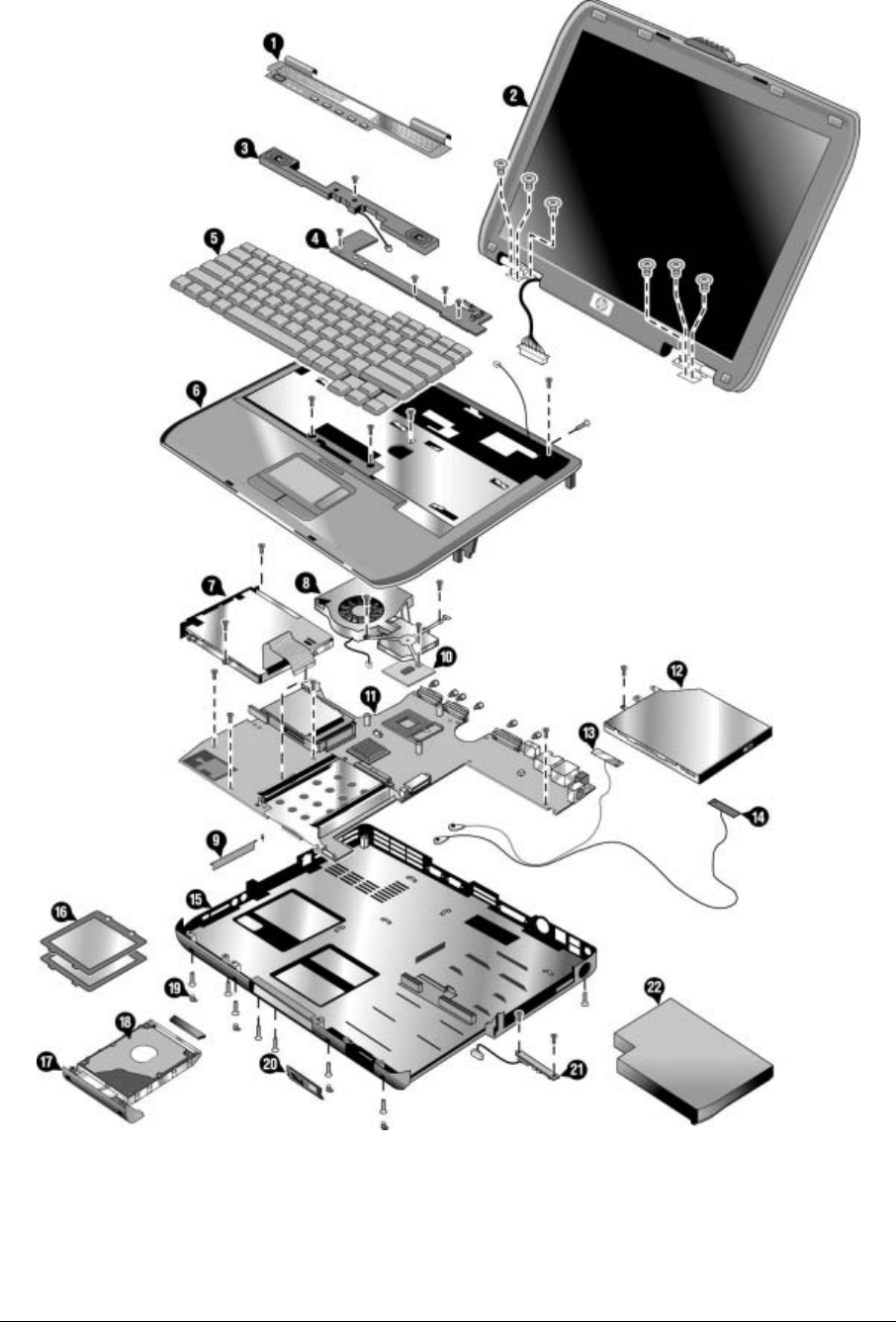
4-2 Replaceable Parts Service Manual
Figure 4-1 Exploded View
HP Pavilion ze4x00,
HP nx9005 and nx9000, and
Compaq Presario 2100
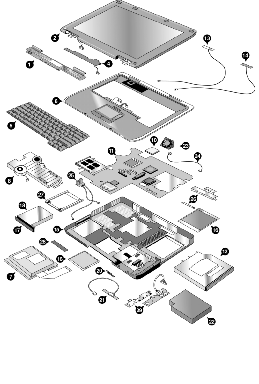
Service Manual Replaceable Parts 4-3
Figure 4-2 Exploded View
HP Pavilion ze5x00,
HP nx9010 and nx9008, and
Compaq Presario 2500

4-4 Replaceable Parts Service Manual
Table 4-1 Replaceable Parts
Description
Part
Number
Exchange
Part
Number
HP Pavilion
ze5x00,
nx9010,
nx9008,
Compaq
Presario
2500
HP Pavilion
ze4x00,
Comapq
Evo N1050v
Compaq
Presario
2100
HP Pavilion
ze4200,
nx9000
Compaq
Presario
2100
Comaq Evo
N1010v
Compaq
Presario
1100
F5771J
HP Pavilion
ze4100
F5761H
User
Repl
1 Cover, Keyboard–1F
Pavilion
F5761-60904
319428-001
• • • No
1 Cover, Keyboard–1F
Compaq
F5771-60904
319430-001
• • No
1 SPS-COVER,
KEYBOARD
W/SPEAKERS CPQ
319479-001 •
No
1 SPS-COVER,
KEYBOARD
W/SPEAKERS PAV
323099-001 •
No
2 Display 150-inch
SXGA+–Pavilion KE
F5761-60912 F5761-69012 • • • No
2 Display 150-inch XGA–
Pavilion KE
F5761-60911
319437-001
F5761-69011 • • • No
2 Display 141-inch XGA–
Pavilion KE
F5761-60910
319436-001
F5761-69010 • • • No
2 Display 150-inch
SXGA+–(Compaq)
F5771-60903 F5771-69003
• No
2 Display 150-inch XGA–
(Compaq)
F5771-60902 F5771-69002
• No
2 Display 141-inch XGA–
(Compaq)
F5771-60901 F5771-69001
• No
2 SPS-DSPLY PANEL
141-inch XGA PAV
319483-001 •
No
2 SPS-DSPLY PANEL
150-inch XGA PAV
319484-001 •
No
2 SPS-DSPLY PANEL
150-inch SXGA PAV
319485-001 •
No
2 SPS-DSPLY PANEL
141-inch SGA PRES
319486-001 •
No
2 SPS-DSPLY PANEL
150-inch SGA PRES
319487-001 •
No
2 SPS-DSPLY PANEL
150-inch SXGA PRES
319488-001 •
No
2 SPS-DSPLY PANEL
150-inch SXGA CPQ
319441-001 • •
No
2 SPS-DSPLY PANEL
150-inch XGA CPQ
319440-001 • •
No
2 SPS-DSPLY PANEL
141-inch XGA CPQ
319439-001 • •
No
3 Speaker assy–1F F4640-60908
319447-001
• • • No
4 PCA, switchboard
w/cable 1F Pavilion
F5761-60905
317445-001
• • • No

Service Manual Replaceable Parts 4-5
Description
Part
Number
Exchange
Part
Number
HP Pavilion
ze5x00,
nx9010,
nx9008,
Compaq
Presario
2500
HP Pavilion
ze4x00,
Comapq
Evo N1050v
Compaq
Presario
2100
HP Pavilion
ze4200,
nx9000
Compaq
Presario
2100
Comaq Evo
N1010v
Compaq
Presario
1100
F5771J
HP Pavilion
ze4100
F5761H
User
Repl
4 PCA, switchboard
w/cable 1F
F4640-60933
• No
5 SPS-KEYBOARD-AR F4640-60909
317443-171
• •
No
5 SPS-KEYBOARD-BEL F4640-60910
317443-181
• •
No
5 SPS-KEYBOARD-BR 317443-201 • •
No
5 SPS-KEYBOARD-CZ F4640-60911
317443-221
• •
No
5 SPS-KEYBOARD-DEN F4640-60912
317443-081
• •
No
5 SPS-KEYBOARD-EUR 317443-021 •
No
5 Keybd, FRENCH F4640-60913
317443-051
• • • • No
5 SPS-KEYBOARD-FC F4640-60914
317443-121
• •
No
5 Keybd, GERMAN F4640-60915
317443-041
• • • • No
5 SPS-KEYBOARD-GRK F4640-60916
317443-151
• •
No
5 SPS-KEYBOARD-HE F4640-60917
317443-BB1
•• No
5 SPS-KEYBOARD-HUN F4640-60918
317443-211
•• No
5 SPS-KEYBOARD-ICL 317443-DD1 •• No
5 SPS-KEYBOARD-INTL F4640-60920
317443-002
• • •
No
5 Keybd, ITALIAN F4640-60921
317443-061
• • • • No
5 Keybd, JAPANESE F4640-60922
317443-291
• • • No
5 SPS-KEYBOARD-KO 317443-AD1 • •
No
5 SPS-KEYBOARD-LA 317443-161 • •
No
5 SPS-KEYBOARD-NO F4640-60923
317443-091
• •
No
5 SPS-KEYBOARD-PRC F4640-60929
317443-AA1
• •
No
5 SPS-KEYBOARD-PT F4640-60924
317443-131
• •
No
5 SPS-KEYBOARD-RU F4640-60925
317443-251
• •
No
5 SPS-KEYBOARD-SK 317443-231 • •
No

4-6 Replaceable Parts Service Manual
Description
Part
Number
Exchange
Part
Number
HP Pavilion
ze5x00,
nx9010,
nx9008,
Compaq
Presario
2500
HP Pavilion
ze4x00,
Comapq
Evo N1050v
Compaq
Presario
2100
HP Pavilion
ze4200,
nx9000
Compaq
Presario
2100
Comaq Evo
N1010v
Compaq
Presario
1100
F5771J
HP Pavilion
ze4100
F5761H
User
Repl
5 Keybd, SPANISH F4640-60926
317443-071
• • • • No
5 SPS-KEYBOARD-SWE F4640-60927
317443-101
• •
No
5 SPS-KEYBOARD-SWI F4640-60928
317443-111
• •
No
5 SPS-KEYBOARD-TAI 317443-AB1 • •
No
5 SPS-KEYBOARD-THAI 317443-281 • •
No
5 SPS-KEYBOARD-TK F4640-60930
317443-141
• •
No
5 Keybd, UK F4640-60931
317443-031
• • • • • No
5 Keybd, US ENGLISH F4640-60932
317443-001
••• •
No
6 Case, top–1F (Pavilion) F5761-60906 •No
6 Case, top–1F FF
(gray/silver)
F4640-60942 •No
6 SPS-CASE, TOP PAV 319426-001 •• No
6 SPS-CASE, TOP CPQ 319427-001 •• No
6 SPS-CASE, TOP
3F CPQ FF
319477-001 •No
6 SPS-CASE, TOP
3F PAV FF
319478-001 •No
6 SPS-CASE, TOP 3F
CPQ DF
322998-001 •No
6 SPS-CASE, TOP 3F
PAV DF
322999-001 •No
6 SPS-COVER,
KEYBOARD
W/SPEAKERS CPQ
319479-001 •No
6 SPS-COVER,
KEYBOARD
W/SPEAKERS PAV
323099-001 •No
7 FDD Assy w/cable 1F F4640-60945
319448-001
••••
No
7 SPS-DRV DSKT
144-MB 3F
320691-001 •No
SPS-COVER DSKT
DRV BLANK
319511-001 •No
Cover, FDD–1F F5761-60901
319432-001
•• •
No

Service Manual Replaceable Parts 4-7
Description
Part
Number
Exchange
Part
Number
HP Pavilion
ze5x00,
nx9010,
nx9008,
Compaq
Presario
2500
HP Pavilion
ze4x00,
Comapq
Evo N1050v
Compaq
Presario
2100
HP Pavilion
ze4200,
nx9000
Compaq
Presario
2100
Comaq Evo
N1010v
Compaq
Presario
1100
F5771J
HP Pavilion
ze4100
F5761H
User
Repl
8 Heat sink–1F w/fan F4640-60947
319456-001
••••
No
8 SPS-HEATSINK 3F
W/2 FANS
319492-001 •No
Thermal pad, set F4640-60984
317438-001
•••••
No
9 Kit, door–PCMCIA 1F
Upper Door w/ Spring
Lower Door w/ Spring
F4640-60965
319431-001
••••
No
9 SPS-DOOR PCMCIA 319494-001 •No
10 SPS-PROC P4 24 GHz 319462-001 •• No
10 SPS-PROC P4 22 GHz 319461-001 •• No
10 SPS-PROC DT P4
22 GHz
319482-001 •No
10 SPS-PROC 24 GHz
400 MHz FSB
323222-001 •No
10 SPS-PROC 24 GHz
533 MHz FSB
323223-001 •No
10 CPU, P4 20 GHz
Northwood uFCPGA
1822-0913
319460-001
F5535-69205 •• •
No
10 CPU, P4 19 GHz
Northwood uFCPGA
1822-1060
319459-001
F5765-69201 •• •
No
10 CPU, P4 18 GHz
Northwood uFCPGA
1822-0819
319458-001
F5535-69202 •• •
No
10 SPS-PROC DT P4
18 GHz
319480-001 •No
10 CPU, P4 17 GHz
Northwood UfcPGA
1822-0781 F3398-69201 •No
10 SPS-PROC P4 16 GHz 1822-0780
319457-001
•• No
10 SPS-PROC C/20 GHz 319466-001 •• No
10 CPU, Cel-M 18 GHz
Northwood uFCPGA
1822-1037
319465-001
F5765-69206 ••••
No
10 CPU, Cel-M 17 GHz
Northwood uFCPGA
1822-0990
319464-001
F5765-69204 •• •
No
10 CPU, Cel-M 16 GHz
Northwood uFCPGA
1822-0989
319463-001
F5765-69203 ••••
No
10 CPU, Cel-M 15 GHz
Northwood UfcPGA
1822-1024 F5765-69202 •No
10 SPS-PROC ATH
XP2000+ 167 GHz
45W
319849-001 •No

4-8 Replaceable Parts Service Manual
Description
Part
Number
Exchange
Part
Number
HP Pavilion
ze5x00,
nx9010,
nx9008,
Compaq
Presario
2500
HP Pavilion
ze4x00,
Comapq
Evo N1050v
Compaq
Presario
2100
HP Pavilion
ze4200,
nx9000
Compaq
Presario
2100
Comaq Evo
N1010v
Compaq
Presario
1100
F5771J
HP Pavilion
ze4100
F5761H
User
Repl
10 SPS-PROC ATH
XP1800+ 153 GHz
45W
319848-001 •No
10 SPS-PROC ATH
XP1700+ 146 GHz
45W
319850-001 •No
11 PCA, motherboard–KE
w/IEEE 1394
Socket, PCMICIA–1F
Guide, HDD–1F
F5761-60902
F4640-60967
F4640-60944
319455-001
•••
•
•
•
•
•
No
No
No
11 PCA, motherboard–KE
w/o IEEE 1394
Socket, PCMICIA–1F
Guide, HDD–1F
F5761-60903
F4640-60967
F4640-60944
319455-001
••••
No
No
No
11 SPS-BD SYSTEM DF 319506-001 •No
11 SPS-BD SYSTEM FF 319507-001 •No
11 SPS-BD SYSTEM DF 319449-001 •No
11 SPS-BD SYSTEM FF 319450-001 •No
11 SPS-BD SYSTEM DF 319612-001 •No
11 SPS-BD SYSTEM FF 319613-001 •No
12 CD-ROM Assy–24x F4640-60934
319420-001
•••••
No
12 DVD Assy–8x F4640-60936
319421-001
•••••
No
12 CD-RW/DVD
Combo Assy
F4640-60937
319422-001
•••••
No
12 SPS-DVD+RW 319423-001 •• No
12 SPS-DRV CD-RW 319419-001 •• No
13 Antennas, Wireless
R&L–1F
F4640-60976
319467-001
•••••
No
14 Antennas, Wireless
R&L–1F
F4640-60976
319467-001
•••••
No
15 Case, bottom assy–FF
XPHome
F4640-60981 •No
15 Case, bottom assy–FF
W2K/XPPro
F4640-60980 •No
15 Case, bottom assy–FF
W2K/XPPro
F4640-60986 ••
No

Service Manual Replaceable Parts 4-9
Description
Part
Number
Exchange
Part
Number
HP Pavilion
ze5x00,
nx9010,
nx9008,
Compaq
Presario
2500
HP Pavilion
ze4x00,
Comapq
Evo N1050v
Compaq
Presario
2100
HP Pavilion
ze4200,
nx9000
Compaq
Presario
2100
Comaq Evo
N1010v
Compaq
Presario
1100
F5771J
HP Pavilion
ze4100
F5761H
User
Repl
15 Case, bottom assy–FF
XPHome
F4640-60987 •No
15 Base Enclosure FF 319469-001 •No
15 Base Enclosure DF 319470-001 •No
15 SPS-ENCLOSURE
BASE DF
317433-001 •• No
15 SPS-ENCLOSURE
BASE FF
317432-001 •• No
Cover, docking port F4640-60966
319435-001
••••
Yes
Cover, modem port F4640-60960
319434-001
••••
Yes
16 Cover, mem or Mini
PCI–1F w/labels
F4640-60901
319433-001
••••
Yes
16 SPS-COVER
MEM/MINI PC 3F
319489-001 •Yes
17 Tray, HDD–1F F4640-60903
319417-001
••••
Yes
18 SPS-DRV HD 60 G
(4200rpm)
319415-001 ••• Yes
18 SPS-DRV HD 60 G
(5400 rpm)
319416-001 •• Yes
18 SPS-DRV HD 80 G
(4200 rpm)
320692-001 ••• Yes
18 HDD-40 GB 95mm,
IBM ATA100 FDB
0950-4320
319414-001
••• •
Yes
18 HDD-40 GB 95mm,
Toshiba ATA100
0950-4288 •Yes
18 HDD-30 GB 95mm,
Hitachi ATA100
0950-4168 ••
Yes
18 HDD-30 GB 95mm,
IBM (diablo) ATA100
0950-4162
319413-001
•••••
Yes
18 HDD-30 GB 95mm,
IBM ATA100 FDB
(Cascade)
0950-4319 ••
Yes
18 HDD-30 GB 95mm,
TITAN Toshiba
ATA100 (TITAN)
0950-4360 ••
Yes
18 HDD-30 GB 95mm,
Toshiba ATA100
0950-4176 ••
Yes
18 HDD-20 GB 95mm,
Hitachi ATA100
0950-4193
319412-001
•••••
Yes
18 HDD-20 GB 95mm,
IBM ATA100 FDB
0950-4318 ••
Yes

4-10 Replaceable Parts Service Manual
Description
Part
Number
Exchange
Part
Number
HP Pavilion
ze5x00,
nx9010,
nx9008,
Compaq
Presario
2500
HP Pavilion
ze4x00,
Comapq
Evo N1050v
Compaq
Presario
2100
HP Pavilion
ze4200,
nx9000
Compaq
Presario
2100
Comaq Evo
N1010v
Compaq
Presario
1100
F5771J
HP Pavilion
ze4100
F5761H
User
Repl
18 HDD-20 GB 95mm,
TOSH ATA100 FDB
0950-4287 ••
Yes
Kit, cable–1F F4640-60974
319424-001
••••
No
Kit, display screw cover F4640-60970
319446-001
••• Yes
Kit, display screw
cover–Pavilion
F5761-60907 •Yes
19 Kit, rubber foot and
screw plug
F4640-60969
317437-001
••••
Yes
20 SPS PANEL IR 3F
W/IR & BUTTON
319502-001 •No
20 SPS PANEL IR 3F
W/IR & W/O BTN
319503-001 •No
20 Panel, IR–1F w/o IR &
w/ button
F4640-60948
317439-001
••••
No
20 Panel, IR–1F w/o IR &
w/o button
F4640-60949
317440-001
••••
No
20 Panel, IR–1F w/IR &
w/button
F4640-60950
317441-001
••••
No
20 Panel, IR–1F w/IR &
w/o button
F4640-60951
317442-001
••••
No
21 SPS-BD IR 3F 319505-001 •No
21 PCA, IR – 1F w/o IR F4640-60964
319454-001
••••
No
21 PCA, IR–1F w/IR F4640-60946
319453-001
••••
No
22 Battery, Li ion 44AHr
8 Cell Li ion
F4809-60901
319411-001
•••••
Yes
23 SPS-FAN 3F SMALL 319490-001 •No
24 SPS-CABLE KIT 3F 319493-001 •No
25 SPS-BD RJ45/1394 319512-001 •No
25 SPS-BD RJ45 319513-001 •No
26 Shield, ESD 3F 323187-001 •No
27 SPS-TRAY, HDD, 3F 335941-001 •No
28 Cover, docking port
HP/Compaq
F4641-60905 •••
Yes
29 SPS-BD AUDIO
CONTROL 3F
319504-001 •No
Service Manual Replaceable Parts 4-11
Table 4-2 Accessory Replaceable Parts
Description
Part
Number
Exchange
Part
Number
HP Pavilion
ze5x00,
nx9010,
nx9008
Compaq
Presario
2500
HP Pavilion
ze4x00,
nx9005,
Compaq
Evo N1050v
Compaq
Presario
2100
HP Pavilion
ze4200,
nx9000
Compaq
Presario
2100
Compaq
Evo N1010v
Compaq
Presario
1100
F5771J
HP Pavilion
ze4100
H5761H
User
Repl
128MB DDR266B F4694-60901
317434-001 ••••
Yes
256MB DDR266B F4695-60901
317435-001 ••••
Yes
512MB DDR266B F4696-60901
317436-001 •• •
Yes
AC-Adapter-Ultraslim
Delta 75W s/PFC
F4600-60901 ••
Yes
Battery, Li ion 44AHr
8 Cell Li ion
F4809-60901
319411-001 •••••
Yes
Card, Mini PCI-80211B
France
F4640-60978
319468-051 ••• •
Yes
Card, Mini PCI-80211B
worldwide
F4640-60977
319468-002 •••••
Yes
Cord, Pwr, Austr
ABG (2w)
8120-6312
317444-011 ••
Yes
Cord, Pwr, Europe
ABB (2w)
8120-6314 ••
Yes
Cord, Pwr, Japan
ABJ (2w)
8120-6316
317444-291 •• Yes
Cord, Pwr, UK (EPSR)
For Hong Kong (2w)
8120-8699
317444-031 •••
Yes
Cord, Pwr, US ABA (2w) 8120-6313
317444-001 ••
Yes
Port Replicator Assy F4808-60901
317448-001 ••••
Yes
Simple Port Replicator
HP/Compaq
F4808-60902 ••
Yes

4-12 Replaceable Parts Service Manual
Table 4-3 Part Number Reference
Part
Description Exchange
Part Number Description
HP Pavilion
ze5x00,
nx9010,
nx9008
Compaq
Presario
2500
HP Pavilion
ze4x00
HP nx9005
Compaq
Evo N1050v
Compaq
Presario
2100
HP Pavilion
ze4200
HP nx9000
Compaq
Presario
2100
Compaq
Evo N1010v
Compaq
Presario
1100
F5771J
HP Pavilion
ze4100
H5761H User
Repl
0950-4162 F2072-69115
HDD-300GB 95mm,
IBM (diablo) ATA100
•••
••
Yes
0950-4168 F3257-69106
HDD-30GB 95mm,
Hitachi ATA100 ••
Yes
0950-4176 F3257-69103
HDD-30GB 95mm,
Toshiba ATA100 ••
Yes
0950-4193 F3257-69105
HDD-20GB 95mm,
Hitachi ATA100
•••
••
Yes
0950-4287 F3476-69002
HDD-20GB 95mm,
TOSH ATA100 FDB ••
Yes
0950-4288 F3378-69102
HDD-40GB 95mm,
Toshiba ATA100 •Yes
0950-4318 F3257-69501
HDD-20GB 95mm,
IBM ATA100 FDB ••
Yes
0950-4319 F3414-69500
HDD-300GB 95mm,
IBM ATA100 FDB
(Cascade)
••
Yes
0950-4320 F3428-69500
HDD-400GB 95mm,
IBM ATA100 FDB
••Yes
0950-4360 F3414-69501
HDD-30GB 95mm,
TITAN Toshiba
ATA100 (TITAN)
••
Yes
1822-0780 SPS-PROC P4 16 GHz •• No
1822-0781 F3398-69201
CPU, P4 17 GHz
Northwood uFCPGA •No
1822-0819 F5535-69202
CPU, P4 18 GHz
Northwood uFCPGA
•• •No
1822-0913 F5535-69205
CPU, P4 20 GHz
Northwood uFCPGA
•• •No
1822-0989 F5765-69203
CPU, Cel-M 16 GHz
Northwood uFCPGA
••
••
No
1822-0990 F5765-69204
CPU, Cel-M 17 GHz
Northwood uFCPGA
•• •No
1822-1024 F5765-69202
CPU, Cel-M 15 GHz
Northwood uFCPGA •No
1822-1037 F5765-69206
CPU, Cel-M 18 GHz
Northwood uFCPGA
••
••
No
1822-1060 F5765-69201
CPU, P4 19 GHz
Northwood uFCPGA
•• •No
7121-7525 Overlay, serial label ••
No
8120-6312 Cord, Pwr, Austr
ABG (2w) •••Yes
8120-6313 Cord, Pwr, US
ABA (2w) •••Yes
8120-6314 Cord, Pwr, Europe ABB
(2w) ••
Yes
8120-6316 Cord, Pwr, Japan
ABJ (2w) •••Yes
8120-8373 SPS-CORD AC PWR
2 WIRE-PRC ••Yes

Service Manual Replaceable Parts 4-13
Part
Description Exchange
Part Number Description
HP Pavilion
ze5x00,
nx9010,
nx9008
Compaq
Presario
2500
HP Pavilion
ze4x00
HP nx9005
Compaq
Evo N1050v
Compaq
Presario
2100
HP Pavilion
ze4200
HP nx9000
Compaq
Presario
2100
Compaq
Evo N1010v
Compaq
Presario
1100
F5771J
HP Pavilion
ze4100
H5761H User
Repl
8120-8699 Cord, Pwr, UK (EPSR)
For Hong Kong (2w) ••••
Yes
317432-001 SPS-ENCLOSURE
BASE FF •• No
317433-001 SPS-ENCLOSURE
BASE DF •• No
317434-001 128MB DDR266B •• Yes
317435-001 256MB DDR266B ••• •
Yes
317436-001 512MB DDR266B •• •
Yes
317437-001 Kit, rubber foot and
screw plug
••
••
Yes
317438-001 Thermal pad, set ••• •
No
317439-001 Panel, IR–1F w/o IR &
w/button
••
••
No
317440-001 Panel, IR–1F w/o IR &
w/o button
••
••
No
317441-001 Panel, IR–1F w/IR &
w/button
••
••
No
317442-001 Panel, IR–1F w/IR &
w/o button
••
••
No
317443-001 Keybd, US ENGLISH ••• •
No
317443-002 SPS-KEYBOARD-INTL ••• No
317443-021 SPS-KEYBOARD-EUR •No
317443-031 Keybd, UK •••••
No
317443-041 Keybd, GERMAN •••• No
317443-051 Keybd, FRENCH ••• •
No
317443-061 Keybd, ITALIAN •••• No
317443-071 Keybd, SPANISH ••• •
No
317443-081 SPS-KEYBOARD-DEN ••No
317443-091 SPS-KEYBOARD-NO ••No
317443-101 SPS-KEYBOARD-SWE ••No
317443-111 SPS-KEYBOARD-SWI ••No
317443-121 SPS-KEYBOARD-FC ••No
317443-131 SPS-KEYBOARD-PT ••No
317443-141 SPS-KEYBOARD-TK ••No

4-14 Replaceable Parts Service Manual
Part
Description Exchange
Part Number Description
HP Pavilion
ze5x00,
nx9010,
nx9008
Compaq
Presario
2500
HP Pavilion
ze4x00
HP nx9005
Compaq
Evo N1050v
Compaq
Presario
2100
HP Pavilion
ze4200
HP nx9000
Compaq
Presario
2100
Compaq
Evo N1010v
Compaq
Presario
1100
F5771J
HP Pavilion
ze4100
H5761H User
Repl
317443-151 SPS-KEYBOARD-GRK ••No
317443-161 SPS-KEYBOARD-LA ••No
317443-171 SPS-KEYBOARD-AR ••No
317443-181 SPS-KEYBOARD-BEL ••No
317443-201 SPS-KEYBOARD-BR ••No
317443-211 SPS-KEYBOARD-HUN ••No
317443-221 SPS-KEYBOARD-CZ ••No
317443-231 SPS-KEYBOARD-SK ••No
317443-251 SPS-KEYBOARD-RU ••No
317443-281 SPS-KEYBOARD-THAI ••No
317443-291 Keybd, JAPANESE ••• No
317443-AA1 SPS-KEYBOARD-PRC ••No
317443-AB1 SPS-KEYBOARD-TAI •• No
317443-AD1 SPS-KEYBOARD-KO •• No
317443-BB1 SPS-KEYBOARD-HE •• No
317443-DD1 SPS-KEYBOARD-ICL •• No
317444-001 Cord, Pwr, US
ABA (2w)
•• •Yes
317444-002 SPS-CORD AC PWR
2 WIRE-INTL
•• Yes
317444-011 Cord, Pwr, Austr
ABG (2w)
••••
•Yes
317444-031 Cord, Pwr, UK (EPSR)
For
Hong Kong (2w)
••
••
Yes
317444-061 SPS-CORD AC PWR
2 WIRE-IT
•• Yes
317444-101 SPS-CORD AC PWR
2 WIRE-SWE
•• Yes
317444-111 SPS-CORD AC PWR
2 WIRE-SWI
•• Yes
317444-291 Cord, Pwr, Japan
ABJ (2w)
••
•Yes
317444-AA1 SPS-CORD AC PWR
2 WIRE-PRC
•• Yes
317444-AB1 SPS-CORD AC PWR
2 WIRE-TAI
•• Yes
317444-AD1 SPS-CORD AC PWR
2 WIRE-KO
•• Yes

4-16 Replaceable Parts Service Manual
Part
Description Exchange
Part Number Description
HP Pavilion
ze5x00,
nx9010,
nx9008
Compaq
Presario
2500
HP Pavilion
ze4x00
HP nx9005
Compaq
Evo N1050v
Compaq
Presario
2100
HP Pavilion
ze4200
HP nx9000
Compaq
Presario
2100
Compaq
Evo N1010v
Compaq
Presario
1100
F5771J
HP Pavilion
ze4100
H5761H User
Repl
317445-001 PCA, switchboard
w/cable 1F Pavilion •• •
No
317446-001 SPS-BD switch w/
cable 1F CPQ •• No
317447-001 SPS-LABEL
NAME SET •• Yes
317448-001 Port Replicator Assy ••• •
Yes
317473-001 Kit, rubber foot and
screw plug
•• Yes
319411-001 Battery, Li ion 44AHr
8 Cell Li ion
••• Yes
319412-001 HDD-20GB 95mm,
Hitachi ATA100
•••
••
Yes
319413-001 HDD-300GB 95mm,
IBM (diablo) ATA100
•••
••
Yes
319414-001 HDD-40 GB 95mm,
IBM ATA100 FDB
••• Yes
319415-001 SPS-DRV HD 60 G
(4200rpm)
••• Yes
319416-001 SPS-DRV HD 60 G
(5400 rpm)
•• Yes
319417-001 Tray, HDD–1F ••
••
Yes
319418-001 Guide, HDD–1F ••
••
No
319419-001 SPS-DRV CD-RW •• No
319420-001 CD-ROM Assy–24X •••
••
No
319421-001 DVD Assy–8x •••
••
No
319422-001 CD-RW/DVD
Combo ASSY •••
••
No
319423-001 SPS-DVD+RW ••
319424-001 Kit, cable–1F ••• •
No
319425-001 Kit, screw ••• •
Yes
319426-001 SPS-CASE, TOP PAV ••No
319427-001 SPS-CASE, TOP CPQ ••No
319428-001 Cover, Keyboard–1F
Pavilion
•••
No
319429-001 SPS-COVER
KEYBOARD EVO
••No
319430-001 Cover, Keyboard–1F
Compaq
••• No
319431-001 Kit, door–PCMCIA ••
••
No

Service Manual Replaceable Parts 4-17
Part
Description Exchange
Part Number Description
HP Pavilion
ze5x00,
nx9010,
nx9008
Compaq
Presario
2500
HP Pavilion
ze4x00
HP nx9005
Compaq
Evo N1050v
Compaq
Presario
2100
HP Pavilion
ze4200
HP nx9000
Compaq
Presario
2100
Compaq
Evo N1010v
Compaq
Presario
1100
F5771J
HP Pavilion
ze4100
H5761H User
Repl
319432-001 Cover, FDD–1F •••
No
319433-001 Cover, mem or
Mini PCI–1F w/labels
••
••
Yes
319434-001 Cover, modem port ••
••
Yes
319435-001 Cover, docking port •• •Yes
19436-001 Display 141-inch XGA–
Pavilion KE
•••
No
319437-001 Display 150-inch XGA–
Pavilion KE
•••
No
319438-001 Display 150-inch
SXGA+–Pavilion KE
•••
No
319439-001 SPS-DSPLY PANEL
150-inch SXGA CPQ
•• No
319440-001 SPS-DSPLY PANEL
150-inch XGA CPQ
•• No
319441-001 SPS-DSPLY PANEL
141-inch XGA CPQ
•• No
319445-001 SPS-BD INVERTER •• No
319446-001 Kit, display screw cover ••• Yes
319447-001 Speaker assy–F ••
•No
319448-001 FDD Assy w/cable–1F ••
••
No
319449-001 SPS-BD SYSTEM DF •No
319450-001 SPS-BD SYSTEM FF •No
319453-001 PCA, IR–1F w/IR ••
••
No
319454-001 PCA, IR–1F w/o IR ••
••
No
319455-001 Socket, PCMCIA–1F ••
••
No
319456-001 Heat sink–1F w/fan ••
••
No
319457-001 SPS-PROC P4 16 GHz •• No
319458-001 CPU, P4 18 GHz
Northwood uFCPGA
•• •No
319459-001 CPU, P4 19 GHz
Northwood uFCPGA
•• •No
319460-001 CPU, P4 20 GHz
Northwood uFCPGA
•• •No
319461-001 SPS-PROC P4 22 GHz •• No
319462-001 SPS-PROC P4 24 GHz •• No

4-18 Replaceable Parts Service Manual
Part
Description Exchange
Part Number Description
HP Pavilion
ze5x00,
nx9010,
nx9008
Compaq
Presario
2500
HP Pavilion
ze4x00
HP nx9005
Compaq
Evo N1050v
Compaq
Presario
2100
HP Pavilion
ze4200
HP nx9000
Compaq
Presario
2100
Compaq
Evo N1010v
Compaq
Presario
1100
F5771J
HP Pavilion
ze4100
H5761H User
Repl
319463-001 CPU, Cel-M 16 GHz
Northwood uFCPGA
••
••
No
319464-001 CPU, Cel-M 17 GHz
Northwood uFCPGA
•• •No
319465-001 CPU, Cel-M 18 GHz
Northwood uFCPGA
••
••
No
319466-001 SPS-PROC C/20 GHz •• No
319467-001 Antennas, Wireless
R&L–1F ••• •
No
319468-002 Card, Mini PCI-80211B
worldwide •••••
Yes
319468-051 Card, Mini PCI-80211B
France ••• •
Yes
319469-001 Base Enclosure FF •No
319470-001 Base Enclosure DF •No
319477-001 SPS-CASE TOP 3F
CPQ FF •No
319478-001 SPS-CASE, TOP 3F
PAV FF •No
319479-001 SPS-COVER,
KEYBOARD
W/SPEAKERS CPQ
•No
319480-001 SPS-PROC DT P4
18 GHZ •No
319482-001 SPS-PROC DT P4
22 GHZ •No
319483-001 SPS-DSPLY PANEL
141-inch XGA PAV •No
319484-001 SPS-DSPLY PANEL
150-inch
XGA PAV
•No
319485-001 SPS-DSPLY PANEL
150-inch
SXGA PAV
•No
319486-001 SPS-DSPLY
PANEL141-inch
SGA PRES
•No
319487-001 SPS-DSPLY PANEL
150-inch
SGA PRES
•No
319488-001 SPS-DSPLY PANEL
150-inch
SXGA PRES
•No
319489-001 SPS-COVER
MEM/MINI PC 3F
•Yes
319490-001 SPS-FAN 3F SMALL •No
319492-001 SPS-HEATSINK 3F
W/2 FANS
•No
319493-001 SPS-CABLE KIT 3F •No

Service Manual Replaceable Parts 4-19
Part
Description Exchange
Part Number Description
HP Pavilion
ze5x00,
nx9010,
nx9008
Compaq
Presario
2500
HP Pavilion
ze4x00
HP nx9005
Compaq
Evo N1050v
Compaq
Presario
2100
HP Pavilion
ze4200
HP nx9000
Compaq
Presario
2100
Compaq
Evo N1010v
Compaq
Presario
1100
F5771J
HP Pavilion
ze4100
H5761H User
Repl
319494-001 SPS-DOOR PCMCIA ••• •
No
319502-001 SPS PANEL IR 3F
W/IR & BUTTON
•No
319503-001 SPS PANEL IR 3F
W/IR & W/O BTN •No
319504-001 SPS-BD AUDIO
CONTROL 3F
•No
319505-001 SPS-BD IR 3F •No
319506-001 SPS-BD SYSTEM DF •No
319507-001 SPS-BD SYSTEM FF •No
319511-001 SPS-COVER DSKT
DRV BLANK •No
319512-001 SPS-BD RJ45/1394 •No
319513-001 SPS-BD RJ45 •No
319612-011 SPS-BD SYSTEM DF •No
319613-001 SPS-BD SYSTEM FF •No
319848-001 SPS-PROC ATH
XP1800+
153-GHz 45W
•No
319849-001 SPS-PROC ATH
XP2000+
167-GHz 45W
•No
319850-001 SPS-PROC ATH
XP1700+
146-GHz 45W
•No
320691-001 SPS-DRV DSKT
144 MB 3F •No
320692-001 SPS-DRV HD 80 G
(4200 rpm) ••• Yes
322998-001 SPS-CASE TOP 3F
CPQ DF •No
322998-001 SPS-CASE, TOP 3F
PAV DF •No
323099-001 SPS-COVER,
KEYBOARD
W/SPEAKERS PAV
•No
323222-001 SPS-PROC 24 GHz
400 MHz FSB •No
323223-001 SPS-PROC 24 GHz
533 MHz FSB •No
F4600-60901 AC-Adapter-Ultraslim
Delta 75W s/PFC ••
Yes
F4640-60901 Cover, mem or
Mini PCI–1F
w/ labels
••
••
Yes

4-20 Replaceable Parts Service Manual
Part
Description Exchange
Part Number Description
HP Pavilion
ze5x00,
nx9010,
nx9008
Compaq
Presario
2500
HP Pavilion
ze4x00
HP nx9005
Compaq
Evo N1050v
Compaq
Presario
2100
HP Pavilion
ze4200
HP nx9000
Compaq
Presario
2100
Compaq
Evo N1010v
Compaq
Presario
1100
F5771J
HP Pavilion
ze4100
H5761H User
Repl
F4640-60903 Tray, HDD–1F ••
••
Yes
F4640-60908 Speaker assy–1F ••
•No
F4640-60909 SPS-KEYBOARD-AR •• No
F4640-60910 SPS-KEYBOARD-BEL •• No
F4640-60911 SPS-KEYBOARD-CZ •• No
F4640-60912 SPS-KEYBOARD-DEN •• No
F4640-60913 Keybd, FRENCH •No
F4640-60914 SPS-KEYBOARD-FC •• No
F4640-60915 Keybd, GERMAN •No
F4640-60916 SPS-KEYBOARD-GRK •• No
F4640-60917 SPS-KEYBOARD-HE •• No
F4640-60918 SPS-KEYBOARD-HUN •• No
F4640-60920 SPS-KEYBOARD-INTL ••• No
F4640-60921 Keybd, ITALIAN ••
•No
F4640-60922 Keybd, JAPANESE ••
•No
F4640-60923 SPS-KEYBOARD-NO •• No
F4640-60924 SPS-KEYBOARD-PT •• No
F4640-60925 SPS-KEYBOARD-RU •• No
F4640-60926 Keybd, SPANISH •No
F4640-60927 SPS-KEYBOARD-SWE •• No
F4640-60928 SPS-KEYBOARD-SWI •• No
F4640-60929 SPS-KEYBOARD-PRC •• No
F4640-60930 SPS-KEYBOARD-TK •• No
F4640-60931 Keybd, UK •••
••
No
F4640-60932 Keybd, US ENGLISH ••• •No
F4640-60933 PCA, switchboard
w/cable–1F
•No
F4640-60934 CD-ROM Assy–24X •••
••
No

Service Manual Replaceable Parts 4-21
Part
Description Exchange
Part Number Description
HP Pavilion
ze5x00,
nx9010,
nx9008
Compaq
Presario
2500
HP Pavilion
ze4x00
HP nx9005
Compaq
Evo N1050v
Compaq
Presario
2100
HP Pavilion
ze4200
HP nx9000
Compaq
Presario
2100
Compaq
Evo N1010v
Compaq
Presario
1100
F5771J
HP Pavilion
ze4100
H5761H User
Repl
F4640-60936 DVD Assy–8x •••
••
No
F4640-60937 F4640-69037 CD-RW/DVD Combo
ASSY •••
••
No
F4640-60942 Case, top–1F
(gray/silver)
•No
F4640-60944 Guide, HDD–1F ••
••
No
F4640-60945 FDD Assy w/cable–1F ••
••
No
F4640-60946 PCA, IR–1F w/IR ••
••
No
F4640-60947 Heat sink–1F w/fan ••
••
No
F4640-60948 Panel, IR–1F w/o IR &
w/button
••
••
No
F4640-60949 Panel, IR–1F w/o IR &
w/o button
••
••
No
F4640-60950 Panel, IR–1F w/IR &
w/button
••
••
No
F4640-60951 Panel, IR–1F w/IR &
w/o button
••
••
No
F4640-60960 Cover, modem port ••
••
Yes
F4640-60964 PCA, IR–1F w/o IR ••
••
No
F4640-60965 Kit, door–PCMCIA ••
••
No
F4640-60966 Cover, docking port •• •Yes
F4640-60967 Socket, PCMCIA–1F ••
••
No
F4640-60969 Kit, rubber foot and
screw plug
••
••
Yes
F4640-60970 Kit, display screw cover ••• Yes
F4640-60974 Kit, cable–1F ••• •
No
F4640-60975 Kit, screw ••• •
Yes
F4640-60976 Antennas, Wireless
R&L–1F ••• •
No
F4640-60977 Card, Mini PCI-80211B
worldwide •••••
Yes
F4640-60978 Card, Mini PCI-80211B
France ••• •
Yes
F4640-60980 F4640-69080 Case, bottom assy–
W2K/XPPro •No
F4640-60981 F4640-69081 Case, bottom assy–
XPHome •No
F4640-60984 Thermal pad, set ••• •
No

4-22 Replaceable Parts Service Manual
Part
Description Exchange
Part Number Description
HP Pavilion
ze5x00,
nx9010,
nx9008
Compaq
Presario
2500
HP Pavilion
ze4x00
HP nx9005
Compaq
Evo N1050v
Compaq
Presario
2100
HP Pavilion
ze4200
HP nx9000
Compaq
Presario
2100
Compaq
Evo N1010v
Compaq
Presario
1100
F5771J
HP Pavilion
ze4100
H5761H User
Repl
F4640-60986 F4640-69086 Case, bottom assy–
w/1394 W2K/XPPro ••
No
F4640-60987 F4640-69087 Case, bottom assy–
w/1394 XPHome •No
F4641-60905 Cover, docking port
hp/Compaq ••
Yes
F4641-60906 Training set,
Series 02-B ••
No
F4694-60901 128MB DDR266B ••• •
Yes
F4695-60901 256MB DDR266B ••• •
Yes
F4696-60901 512MB DDR266B •• •
Yes
F4808-60901 Port Replicator Assy ••• •
Yes
F4808-60902 Simple Port Replicator
hp/Compaq ••
Yes
F4809-60901 Battery, Li ion 44AHr 8
Cell
Li ion
•• •
Yes
F5761-12001 CD, Rec XP Home NA
ENG •No
F5761-12003 CD, Rec XP Home
AUS EN •No
F5761-12006 CD, Rec XP Home NA
ENG •No
F5761-60901 Cover, FDD–1F •••
No
F5761-60902 F5761-69002 PCA, motherboard–KE
w/IEEE 1394 ••
No
F5761-60903 F5761-69003 PCA, motherboard–KE
w/o IEEE 1394 ••
No
F5761-60904 Cover, Keyboard–1F
Pavilion
•••
No
F5761-60905 PCA, switchboard
w/cable–1F Pavilion •• •
No
F5761-60906 Case, top–1F (Pavilion) •No
F5761-60907 Kit, display screw
cover–Pavilion •No
F5761-60910 F5761-69010 Display 141-inch XGA–
Pavilion KE
•••
No
F5761-60911 F5761-69011 Display 150-inch XGA–
Pavilion KE
•••
No
F5761-60912 F5761-69012 Display 150-inch
SXGA+–Pavilion KE
•••
No
F5761-60913 Label, Name set–KE ••
Yes
F5771-60901 F5771-69001 Display 141-inch XGA–
(Compaq) •No
F5771-60902 F5771-69002 Display 150-inch XGA–
(Compaq) •No

Service Manual Replaceable Parts 4-23
Part
Description Exchange
Part Number Description
HP Pavilion
ze5x00,
nx9010,
nx9008
Compaq
Presario
2500
HP Pavilion
ze4x00
HP nx9005
Compaq
Evo N1050v
Compaq
Presario
2100
HP Pavilion
ze4200
HP nx9000
Compaq
Presario
2100
Compaq
Evo N1010v
Compaq
Presario
1100
F5771J
HP Pavilion
ze4100
H5761H User
Repl
F5771-60903 F5771-69003 Display 150-inch
SXGA+(Compaq) •No
F5771-60904 Cover, Keyboard–1F
Compaq
••• No
F5781-12004 CD, Rec XP Home UK
ENG •No

Service Manual Reference Information 5-1
5
Reference Information
This chapter includes the following reference information:
• Password removal policy
• Display quality statement

5-2 Reference Information Service Manual
Password Removal Policy
If the user forgets the system password, the user calls Technical Support to determine the proper removal
procedure The user must provide proof of ownership and the notebook must be operated during the
procedure.
The password removal procedure is protected as HP Company Private information There are a restricted
number of locations that can perform password removal It might not be disclosed or distributed outside
those locations.
Password removal is strictly controlled Hewlett-Packard and authorized support providers must ensure
with written evidence that the notebook being “cleansed” is actually in the possession of the notebook’s
actual and current owner This requires a sales receipt showing the notebook serial number and owner’s
name, or a written statement from the owner attesting that he or she is the owner of the notebook The
statement can be a fax copy of the document The fact that the notebook is in the hands of an HP
representative on behalf of the customer is not evidence of ownership In addition, HP will not remove the
password of a notebook for any non-owner, even if it is requested by law enforcement agencies If you
receive such a request, you should notify management and HP Corporate Legal immediately. (These
requests might require a court order prior to our participation.)
Further, the entity removing the password must log the name, serial number and date of the removal, and
file the written backup with the log The log and backup are subject to standard record retention process and
review.
The final issue relating to removal of passwords is that HP cannot provide information to users that would
assist them in improperly removing a password and opening a notebook.

Service Manual Reference Information 5-3
Hewlett-Packard Display Quality Statement
TFT display manufacturing is a highly precise but imperfect technology, and manufacturers cannot
produce large displays that are cosmetically perfect Most, if not all, TFT displays exhibit some level of
cosmetic imperfection These cosmetic imperfections might be visible to the customer under varying
display conditions, and can appear as bright, dim, or dark spots This issue is common across all vendors
supplying TFT displays in their products and is not specific to the notebook display.
Notebook TFT displays meet or exceed all HP standards for cosmetic quality of TFT displays HP does not
warrant that the displays will be free of cosmetic imperfections TFT displays can have a small number of
cosmetic imperfections and still conform to HP’s cosmetic quality specifications.
Here are some guidelines for determining what action to take on customers’ complaints of cosmetic
imperfections in their TFT displays:
1. View the notebook under the customer’s normal operating conditions.
This means that if the customer uses the unit predominately in DOS, in Windows, or in some other
application or combination of applications, you should make the determination under those same
applications Self test is not a normal operating condition and is not a sufficient tool for interpreting
display quality.
2. Use the table below to determine whether the display should be considered for replacement These are
the only conditions in this guideline that might call for a replacement due to a defect in material or
workmanship based on the HP Limited Warranty Statement.
3. If a display is considered for replacement, make sure the customer understands that cosmetic variations
might also exist on the replacement display, and might require the customer to use a work-around to
obscure the cosmetic imperfection.
4. Customers with cosmetic-based complaints that do not conform to the above conditions and tests will
not normally be considered for display replacement The HP-responsible person working with the
customer should identify work-around solutions that are reasonable and appropriate for the individual
customer Customers who must have a more perfect display solution should consider switching to a
notebook with a DSTN display.
We expect that over time the industry will continue to produce displays with fewer inherent cosmetic
imperfections, and we will adjust our HP guidelines as these improvements are implemented.

5-4 Reference Information Service Manual
Table 5-1 LCD Guidelines
Type of Imperfection Imperfections Not Allowed
Electrical Imperfections:
Bright dots (a)
Dark dots (a)
• 7 or more single bright dots
• 7 or more single dark dots
• 9 or more total (bright and dark combined) defective dots
• Any occurrence of multiple defective dots within 15 mm
Mechanical Imperfections:
Discoloration
Polarizer bubbles, dents (b)
• Any polarizer bubble, discoloration, or dent that is visible from at least 36
cm (14 in)
Definitions of imperfections:
aBright or dark dot: a subpixel (red, green, or blue dot) that is stuck on or off.
bPolarizer dent or bubble: a light spot with a darker border that appears on a lighted display and does not
change size (In contrast, a polarizer scratch is a light line that is visible on a darker background and
does not change size)

Service Manual Reference Information 5-5
Service Notes and Obsolete Parts
Service notes containing important repair information for these products will be issued as needed These
notes are available online at the Partnership Web site (see page vii).
