Huace Navigation Technology A02003 GNSS receiver User Manual SY4 A02003 User Manual Rev2
Shanghai Huace Navigation Technology LTD. GNSS receiver SY4 A02003 User Manual Rev2
Contents
- 1. User Manual
- 2. Users Manual
User Manual

SafetyInformation
il
CHC®N72™GNSSReference
Receiver
Revision1.0
January2015
N72GNSSReferenceReceiverUserGuidePage1
Copyright
Copyright2009‐2015CHC|ShanghaiHuaCe
NavigationTechnologyLtd.Allrightsreserved.The
CHCaretrademarkofShanghaiHuaCeNavigation
TechnologyLimited.Allothertrademarksarethe
propertyoftheirrespectiveowners.
Trademarks
Allproductandbrandnamesmentionedinthis
publicationaretrademarksoftheirrespective
holders.
SafetyWarnings
TheGlobalPositioningSystem(GPS)isoperatedby
theU.S.Government,whichissolelyresponsible
fortheaccuracyandmaintenanceoftheGPS
network.Accuracycanalsobeaffectedbypoor
satellitegeometryandobstructions,likebuildings
andheavycanopy.
FCCinterferencestatement
Thisequipmenthasbeendesignedtocomplywith
thelimitsforaClassBdigitaldevice,pursuantto
part15oftheFCCRulesinthePortableMode.
Theselimitsaredesignedtoprovidereasonable
protectionagainstharmfulinterferenceina
residentialinstallation.
Operationissubjecttothefollowingtwo
conditions:(1)thisdevicemaynotcauseharmful
interferenceand(2)thisdevicemustacceptany
interferencereceived,includinginterferencethat
maycauseundesiredoperation.
Note:
THEGRANTEEISNOTRESPONSIBLEFORANY
CHANGESORMODIFICATIONSNOTEXPRESSLY
APPROVEDBYTHEPARTYRESPONSIBLEFOR
COMPLIANCE.SUCHMODIFICATIONSCOULDVOID
THEUSER’SAUTHORITYTOOPERATETHE
EQUIPMENT
Thisproducthasbeentestedandfoundtocomply
withthelimitsforPart15oftheFCCRules.These
limitsaredesignedtoprovidereasonable
protectionagainstharmfulinterferenceina
residentialinstallation.Thisproductgenerates,
uses,andcanradiateradiofrequencyenergyand,
ifnotinstalledandusedinaccordancewiththe
instructions,maycauseharmfulinterferenceto
radiocommunications.However,thereisno
guaranteethatinterferencewillnotoccurina
particularinstallation.Ifthisproductdoescause
harmfulinterferencetoradioortelevision
reception,whichcanbedeterminedbyturningthe
equipmentoffandon,theuserisencouragedto
trytocorrecttheinterferencebyoneormoreof
thefollowingmeasures:
—Reorientorrelocatethereceivingantenna.
—Increasetheseparationbetweentheequipment
andreceiver.
—Connecttheequipmentintoanoutletona
circuitdifferentfromthattowhichthereceiveris
connected.
—Consultthedealeroranexperiencedradio/TV
technicianforhelp.
N72GNSSReferenceReceiverUserGuide–
Revision1.0January2015
N72GNSSReferenceReceiverUserGuidePage2
SAFETYINFORMATION
BeforeyouuseyourCHC®N72™GNSSreferencereceiver,makesurethat
youhavereadandunderstoodallsafetyrequirements.
REGULATIONSANDSAFETY
Thereceivercontainsaninternalwirelessmodemforcommunicatingsignals
throughBluetooth®wirelesstechnologyorthroughanexternaldata
communicationsradio.Regulationsregardingtheuseofthewirelessmodem
varygreatlyfromcountrytocountry.Insomecountries,theunitcanbeused
withoutobtaininganend‐userlicense.Othercountriesrequireend‐user
licensing.Forlicensinginformation,consultyourlocalCHCdealer.
BeforeoperatingaN72GNSSreferencereceiver,determineifauthorization
oralicensetooperatetheunitisrequiredinyourcountry.Itisthe
responsibilityoftheend‐usertoobtainanoperator'spermitorlicensefor
thereceiverforthelocationorcountryofuse.
TYPEAPPROVAL
Typeapproval,oracceptance,coverstechnicalparametersoftheequipment
relatedtoemissionsthatcancauseinterference.Typeapprovalisgrantedto
themanufacturerofthetransmissionequipment,independentfromthe
operationorlicensingoftheunits.Somecountrieshaveuniquetechnical
requirementsforoperationinparticularradiomodemfrequencybands.To
complywiththoserequirements,CHCmayhavemodifiedyourequipmentto
begrantedTypeapproval.Unauthorizedmodificationoftheunitsvoidsthe
Typeapproval,thewarranty,andtheoperationallicenseoftheequipment.
EXPOSURETORADIOFREQUENCYRADIATION
Safety.ExposuretoRFenergyisanimportantsafetyconsideration.TheFCC
hasadoptedasafetystandardforhumanexposuretoradiofrequency
electromagneticenergyemittedbyFCCregulatedequipment.Properuseof
thisradiomodemresultsinexposurebelowgovernmentlimits.The
followingprecautionsarerecommended:
Donotoperatethetransmitterwhensomeoneis20cm(7.8inches)of
theantenna.
DonotoperatethetransmitterunlessallRFconnectorsaresecureand
anyopenconnectorsarecorrectlyterminated.
Donotoperatetheequipmentnearelectricalblastingcapsorinan

SafetyInformation
N72GNSSReferenceReceiverUserGuidePage3
explosiveatmosphere.
Allequipmentmustbecorrectlygroundedforsafeoperation.
Allequipmentshouldbeservicedonlybyaqualifiedtechnician.
BATTERYSAFETY
WARNING–DonotdamagetherechargeableLithium‐ionbattery.A
damagedbatterycancauseanexplosionorfire,andcanresultinpersonal
injuryand/orpropertydamage.Topreventinjuryordamage:
– Donotuseorchargethebatteryifitappearstobedamaged.Signs
ofdamageinclude,butarenotlimitedto,discoloration,warping,
andleakingbatteryfluid.
– Donotexposethebatterytofire,hightemperature,ordirect
sunlight.
– Donotimmersethebatteryinwater.
– Donotuseorstorethebatteryinsideavehicleduringhotweather.
– Donotdroporpuncturethebattery.
– Donotopenthebatteryorshort‐circuititscontacts.
WARNING–AvoidcontactwiththerechargeableLithium‐ionbatteryifit
appearstobeleaking.Batteryfluidiscorrosive,andcontactwithitcanresult
inpersonalinjuryand/orpropertydamage.Topreventinjuryordamage:
– Ifthebatteryleaks,avoidcontactwiththebatteryfluid.
– Ifbatteryfluidgetsintoyoureyes,immediatelyrinseyoureyeswith
cleanwaterandseekmedicalattention.Donotrubyoureyes!
– Ifbatteryfluidgetsontoyourskinorclothing,immediatelyuse
cleanwatertowashoffthebatteryfluid.
WARNING–ChargeandusetherechargeableLithium‐ionbatteryonlyin
strictaccordancewiththeinstructions.Chargingorusingthebatteryin
unauthorizedequipmentcancauseanexplosionorfire,andcanresultin
personalinjuryand/orequipmentdamage.Topreventinjuryordamage:
– Donotchargeorusethebatteryifitappearstobedamagedor
leaking.
– ChargetheLithium‐ionbatteryonlyinaCHCproductthatis
specifiedtochargeit.
– Discontinuechargingabatterythatgivesoffextremeheatora
burningodor.
– UsethebatteryonlyinCHCequipmentthatisspecifiedtouseit.
– Usethebatteryonlyforitsintendeduseandaccordingtothe
instructionsintheproductdocumentation.
SafetyInformation
N72GNSSReferenceReceiverUserGuidePage4
DCPOWERSUPPLYSAFETY
WARNING–WhenDCvoltageisappliedtothisreceiverthroughCOM1or
COM2(Lemoconnectors),theDCvoltagemustbelimitedtonomorethan
36VDC+0%underbothnormalandsinglefaultconditions.Ifthe
recommendedinputvoltageisexceeded,thereceivermaypresentan
electricalhazard.
WETLOCATIONSAFETY
WARNING–Thisreceiverisnotintendedtobeusedinawetlocation,ora
locationthatmaybecomewet,whenitispoweredbytheexternalDCpower
supply.Usethereceiverinawetlocationonlywhenoperatingitonitsown
internalbattery.
WARNING–Theexternalpoweradapteranditsassociatedpowercordand
plugarenotintendedtobeinstalledoutdoors,orinawetlocation.
WARNING–Donotpowerthereceiverthroughexternalpowerwhen
operatinginawetenvironmentoranenvironmentthatmaybecomewet.
Thepowerinputconnectionsmustbesheltered.
N72GNSSReferenceReceiverUserGuidePage5
CONTENTS
SafetyInformation...........................................................................................................................................2
Regulationsandsafety.............................................................................................................................2
Typeapproval..........................................................................................................................................2
Exposuretoradiofrequencyradiation....................................................................................................2
Batterysafety...........................................................................................................................................3
DCpowersupplysafety...........................................................................................................................4
Wetlocationsafety..................................................................................................................................4
1.Introduction.................................................................................................................................................7
1.1.Aboutthereceiver............................................................................................................................7
1.2.Technicalsupport..............................................................................................................................7
1.3.Disclaimer.........................................................................................................................................8
1.4.Yourcomments.................................................................................................................................8
2.Overview......................................................................................................................................................9
2.1.Receiverframework..........................................................................................................................9
2.1.1.Thenetworkapplianceconcept..........................................................................................10
2.2.Receiverservices.............................................................................................................................10
2.3.Receiverfeatures............................................................................................................................11
2.4.Useandcare...................................................................................................................................11
2.5.Electronicinterface.........................................................................................................................12
2.6.Keypadanddisplay.........................................................................................................................12
2.7.Rearconnectors..............................................................................................................................13
3.BatteriesandPower..................................................................................................................................15
3.1.Externalpower................................................................................................................................15
3.2.Batterysafety..................................................................................................................................16
3.3.Batteryperformance......................................................................................................................16
3.4.Chargingthebattery.......................................................................................................................17
3.5.Storingthebattery..........................................................................................................................17
3.6.Removingthebattery.....................................................................................................................17
4.SettingUptheReceiver.............................................................................................................................19
4.1.Guidelines.......................................................................................................................................19
4.1.1.Environmentalconditions....................................................................................................19
4.1.2.Sourcesofelectricalinterference........................................................................................19
4.1.3.Uninterruptablepowersupply.............................................................................................19
4.1.4.Lightingandsurgeprotection..............................................................................................20
4.1.5.Placingtheantenna.............................................................................................................20
4.2.Systeminstallation..........................................................................................................................21
4.2.1.Supportedantenna..............................................................................................................21
4.2.2.Systeminstallationdiagram.................................................................................................21
5.ConfiguringtheReceiver:KeypadandDisplay..........................................................................................23
5.1.Buttonfunctions.............................................................................................................................23
5.2.Homescreen...................................................................................................................................23
5.3.Statusscreens.................................................................................................................................24
N72GNSSReferenceReceiverUserGuidePage6
5.4.SettingupthereceiveraspartofanEthernetconfiguration.........................................................25
6.ConfiguringtheReceiver:OtherThanKeypadandDisplay.......................................................................26
6.1.ConfiguringtheEthernetsettings...................................................................................................26
6.2.Configuringthroughawebbrowser...............................................................................................27
6.2.1.Changingthesettings..........................................................................................................28
6.2.1.1.Statusmenu..............................................................................................................28
6.2.1.2.Satellitesmenu.........................................................................................................31
6.2.1.3.ReceiverSettingsmenu............................................................................................33
6.2.1.4.DataRecordingmenu...............................................................................................36
6.2.1.5.IOSettingsmenu.......................................................................................................40
6.2.1.6.GPRSmenu...............................................................................................................44
6.2.1.7.Radiomenu...............................................................................................................44
6.2.1.8.WANmenu................................................................................................................45
6.2.1.9.Wifimenu.................................................................................................................47
6.2.1.10.BluetoothSetmenu................................................................................................48
6.2.1.11.NetworkServicemenu...........................................................................................48
6.2.1.12.Firmwaremenu....................................................................................................497
7.DefaultSettingandConfigurationFiles.....................................................................................................50
7.1.Defaultreceiversettings.................................................................................................................50
7.1.1.Resettingthereceivertofactorydefaults............................................................................50
7.1.2.Usingconfigurationfilestoduplicatereceiversettings.......................................................53
8.Specifications.............................................................................................................................................54
8.1.GNSScharacteristics.......................................................................................................................54
8.2.Communication..............................................................................................................................54
8.3.Physical...........................................................................................................................................55
8.4.Electrical.........................................................................................................................................55
8.5.General...........................................................................................................................................55
8.6.Datastorage....................................................................................................................................56
A.UpgradingtheReceiverFirmware.............................................................................................................57
A.I.TheWinFlashutility.........................................................................................................................57
A.I.i.InstallingtheWinFlashutility................................................................................................57
A.II.Upgradingthereceiverfirmware...................................................................................................57
A.II.i.UpgradingthroughUSBport................................................................................................57
A.II.ii.Upgradingthroughabrowser..............................................................................................58
B.Troubleshooting.........................................................................................................................................59
B.I.Receiverissues.................................................................................................................................59
C.CommunicationPortsDefinition...............................................................................................................61
C.I.CHCN72ReceiverCOM1(10‐PINLEMOPort)Definition...............................................................61
C.II.CHCN72ReceiverCOM2(10‐PINLEMOPort)Definition..............................................................61
C.III.CHCN72ReceiverDB9MaleConnectorDefinition.......................................................................62
D.Glossary.....................................................................................................................................................63
N72GNSSReferenceReceiverUserGuidePage7
1. INTRODUCTION
TheN72GNSSReferenceReceiverUserGuidedescribeshowtosetupand
usetheCHC®N72™GNSSreferencereceiver.
Inthismanual,“thereceiver”referstotheN72GNSSreferencereceiver
unlessotherwisestated.
EvenifyouhaveusedotherGlobalNavigationSatelliteSystems(GNSS)
productsbefore,CHCrecommendsthatyouspendsometimereadingthis
manualtolearnaboutthespecialfeaturesofthisproduct.Ifyouarenot
familiarwithGNSS,gotowww.chcnav.comforaninteractivelookatCHC
andGNSS.
1.1. ABOUTTHERECEIVER
TheN72GNSSreferencereceiver(“thereceiver”)isamultiple‐frequency
GNSSreceiver.ItcantrackallGPS(L1/L2/L5),GLONASS(L1/L2)andBDS
(B1/B2)signals.
Youcanusethefrontpanelofthereceiveroranofficecomputerto
configurethereceiver,accessfiles,andpublishdatafilestoacompany
IntranetortotheInternet.Thereceivermakesiteasyforyoutosetupa
powerful,flexible,andreliablereferencestationforcontinuousoperation.
Thereceiverservesinallcommongeodeticreferencereceiverroles.Itcan
bethemaincomponentinaContinuouslyOperatingReferenceStation
(CORS),streamingdatatoCHCGNSSInfrastructuresoftware.Itcanalsowork
wellasacampaignreceiverpriortopermanentdeployment.Thereceiver
makesanexcellentportableRTKbasestationwithitsinternalbattery.Italso
hasspecializedcapabilitiesthatmakeitanexcellentreferencereceiverfor
scientificapplications.
1.2. TECHNICALSUPPORT
Ifyouhaveaproblemandcannotfindtheinformationyouneedinthe
productdocumentationorCHCwebsite(www.chcnav.com),contactyour
localCHCdealerfromwhichyoupurchasedthereceiver(s).
IfyouneedtocontactCHCtechnicalsupport,pleasecontactusbyemail
(support@chcnav.com)orSkype(chc_support).

1.Introduction
N72GNSSReferenceReceiverUserGuidePage8
1.3. DISCLAIMER
Beforeusingthereceiver,pleasemakesurethatyouhavereadand
understoodthisUserGuide,aswellasthesafetyrequirements.CHCholds
noresponsibilityforthewrongoperationbyusersandforthelosses
incurredbythewrongunderstandingaboutthisUserGuide.However,CHC
reservestherightstoupdateandoptimizethecontentsinthisguide
regularly.PleasecontactyourlocalCHCdealerfornewinformation.
1.4. YOURCOMMENTS
Yourfeedbackaboutthisuserguidewillhelpustoimproveitinfuture
revision.Pleaseemailyourcommentstosupport@chcnav.com.

N72GNSSReferenceReceiverUserGuidePage9
2. OVERVIEW
ThischapterintroducestheN72GNSSreferencereceiver(“thereceiver”).
ThisreceivermakesiteasytosetupapowerfulandreliableContinuously
OperatingReferenceStation(CORS)ortocollectdatafromtemporaryfield
locations.
Thereceiverisidealforthefollowinginfrastructureapplications:
AspartofaGNSSInfrastructurenetworkinconjunctionwithCHC
ReferenceStationNetwork(CRNet)software.
Aspartofapermanentreferencestationwithorwithoutsupporting
software.
AtemporaryfieldbasestationtobroadcastRTKcorrectionsandcollect
observationsforpostprocessing.
2.1. RECEIVERFRAMEWORK
Thereceiverintegratesthemulti‐frequencyGNSStechnologyintoa
specializedprocessingandcommunicationsframework.Thereceivercan
operateasastandalonereferencestationoritcanbeintegratedintoa
scalablenetwork.
WithanInternetProtocol(IP)astheprimarycommunicationsmethod,you
canusepublicdomaintools,suchasawebbrowserandFTPclient,to
configurethereceiverandaccessloggeddatafiles.
NOTE‐AllreferencestotheInternetrefertoeitheraWideArea
Network(WAN)oraLocalAreaNetwork(LAN)connection.
Thereceiveradoptsasecuredsystemthatrequiresapasswordprotected
loginforconfigurationchangesand/orfileaccess.
Usethenetworkmanagementfeaturestocreateabase/roverconfiguration
withavarietyofoperatingmodes.Youcanthenenablethosemodesas
necessaryinsteadofswitchingtheglobalstateofthereceiverfromone
modetoanother.Forexample,youcanconfigureanumberofstreaming
serviceswithdifferentconfigurations(suchasanycombinationofdata
stream,sampleinterval)ondifferentTCPorUDPports.Toactivateoneor
moremodes,opentheconnectiontothespecificport.Thisallowsmultiple
clientstoaccessanygivenstreamingservice.
Thesefeaturesandmanymore,shiftthemodelofaGNSSreceivertoward
theconceptofa"networkappliance".

2.Overview
N72GNSSReferenceReceiverUserGuidePage10
2.1.1. THENETWORKAPPLIANCECONCEPT
Traditionally,aGNSSreceiverhasoneoperator.Thatpersonistheonlyuser
ofthereceiversotheycanchangesettingswithoutaffectingotherusers.
WiththeN72GNSSreferencereceiver,anoperatorcanconfigureareceiver
once,andthenmakeitavailableasanetworkapplianceforgeneraluseby
oneormoreusers(orclients).
Thisnetworkapplianceconceptletsyousetupthereceivertoprovideone
ormoreservicesthatoneormoreuserscanaccessthroughaLocalArea
Network(LAN)oraWideAreaNetwork(WAN),suchastheInternet.Once
thereceiverissetup,youneedmakeonlyminimalchanges,ifany,tothe
receiverconfiguration.
Whenthereceiverisoperatingasanetworkappliance,itprovidesservices
toallusersattachedtothereceiverthroughthenetwork.
Differentstreamedservicesmaybeconfiguredondifferentports,for
example,withdifferingdataratesordatacombination.Toobtainaservice,
theclienthasonlytoconnecttoaspecificport.Inthisway,mostusersdo
notneedtocontrolthereceiver.Changingglobalsettings,suchasmasks,will
affectallusersofallservices.
Thereceiverprovidesthefollowingstandardconfigurationanddatalogging
services:
Use... Toperform...
HTTP Allmanualandautomatedconfigurationoperationstomanage
theloggeddatafilespace.
FTPRemotemanualand/orautomatedoperationstomanagethe
loggeddatafileuploadpath.
2.2. RECEIVERSERVICES
Thereceivercanprovideoneormorestreamingorqueryservicesovera
RS‐232serialportoraTCP/IPport:
Streamingservice
Anyonewithauthorizedaccesscanobtainstreamedinformation,such
asGNSSmeasurementsorRTCMcorrections,withouthavingtocontrol
orissuecommandstothereceiver.Theclientsimplyconnectstothe
portthatisstreamingtherequiredinformation.

2.Overview
N72GNSSReferenceReceiverUserGuidePage11
2.3. RECEIVERFEATURES
220‐channels
– GPS:L1C/A,L2C,L2E,L5
– GLONASS:L1C/A,L1,L2C/A,L2P
– Galileo:E1,E5A,E5B
– SBAS:WAAS,EGNOS,MSAS
– BDS:B1,B2
16GBinternaldataloggingstorage
ExternalUSBdrivesupport
Integratedbattery,providesupto17hoursoperation
Integrateddisplayandkeypadforsystemconfigurationwithouta
controller
IntegratedBluetoothwirelesstechnologyforcable‐freedata
transmission
Permanent/semi‐permanentandmobilequicksetupbasestation
capability
Easy‐to‐useWeb‐interfacemenusystemforrapidconfigurationand
statuschecking
Rugged,weatherproofconstructionwithanIP67environmentalrating
‐40°Cto+65°C(‐40°Fto+149°F)operatingtemperaturerange
12Vto36VDCinputpowerrange
DatafilegeneratedinHCN
IMX287processorbasedonembeddedLinux,mainfrequencyupto
450MHz
Eightindependentdataloggingsessionswithconfigurablememory
pooling
Circulatingdataloggingmethod
FTPpushtoallowuploadingofloggeddatafilestoremotesites
Ethernetconfigurationthroughthefrontpanel
MultiplelanguagesavailablethroughtheWebinterface
NTRIP(NetworkedTransportofRTCMviaInternetProtocol)
client/server/castersupport
2.4. USEANDCARE
Thisreceivercanwithstandtheroughtreatmentandtoughenvironment
thattypicallyoccursinCORSinstallation.However,itisahigh‐precision
electronicinstrumentandshouldbetreatedwithreasonablecare.
CAUTION–Operatingorstoringthereceiveroutsidethespecified
temperaturerangecandamageit.Formoreinformation,seeChapter8
Specifications.
2.Overview
N72GNSSReferenceReceiverUserGuidePage12
2.5. ELECTRONICINTERFACE
High‐powersignalsfromanearbyradioorradartransmittercanoverwhelm
thereceivercircuits.Thisdoesnotharmtheinstrument,butitcanprevent
thereceiverelectronicsfromfunctioningcorrectly.
Avoidlocatingthereceiverorantennawithin400metersofpowerfulradar,
television,orothertransmittersorGNSSantennas.Low‐powertransmitters,
suchasthoseincellphonesandtwo‐wayradios,normallydonotinterfere
withreceiveroperations.
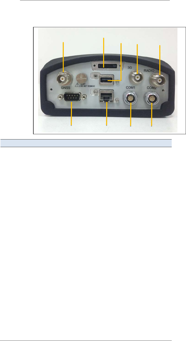
2.6. KEYPADANDDISPLAY
Feature Description
1PowerLEDShowsifthepowerisonoroff.
2Buttons Usetoturnon,turnofforconfigurethereceiver.See
5.1.Buttonfunctions.
3DisplayThisVacuumFluorescentdisplayenablesyouviewthe
currentconfigurationsettingsofreceiverandthe
operationbyoperators.See5.3.Homescreen.
1
22
3
2.Overview
N72GNSSReferenceReceiverUserGuidePage13
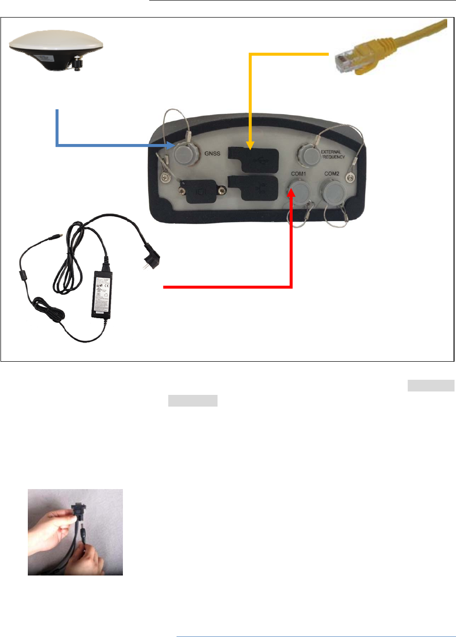
2.7. REARCONNECTORS
2.8.
Connectortype Description
1TNCConnecttotheGNSSantenna
2SIMcardslotSIMcardisinsertedheretoconnectGPRSnetwork
3USB ConnecttoexternalUSBdriveforexternaldata
loggingafterconfiguredthroughwebinterface.
Upgradethereceiverfirmwarewiththe
insertedUSBdrivercontainingtherelated
upgradefileafterrestartthereceiver.
Connectthereceivertoacomputerto
downloadfilesfromthereceiver(asexternal
storageequipment)tothecomputer.
4TNCForexternalGPRSantenna
5TNCForexternalradio
6DB9RS‐232serialport,9‐pinmaleconnector,fordata
communicationwhennecessary
7RJ45jack Supportslinksto10BaseT/100BaseT
auto‐negotiatenetworks
HTTP,TCP/IP,UDP,FTP,NTRIPCaster,NTRIP
Server,NTRIPClient
Simultaneouslytransmitsmultipledatastream
8Lemo(10‐pin)Port1 PowerfromanexternalAC/DCpowersupply.
RS‐232serialcommunicationsusinga10‐pin
Lemocable(CHCDataCable).
Pass‐throughtothemainboardwithoutissuing
thepass‐throughcommandviathisport.
9Lemo(10‐pin)Port2 PowerfromanexternalAC/DCpowersupply.
RS‐232serialcommunicationsusinga10‐pin
14
3
5
2
6789

2.Overview
N72GNSSReferenceReceiverUserGuidePage14
Lemocable(CHCDataCable).
Datastreamingtransmissionport.

N72GNSSReferenceReceiverUserGuidePage15
3. BATTERIESANDPOWER
TheN72GNSSreferencereceiverusesaninternalrechargeableLithium‐ion
battery,whichcanbereplacedonlyatanAuthorizedCHCServiceCenter.
Thereceivercanalsobepoweredbyanexternalpowersourcethatis
connectedtoeitheroftheLemoports.
Theoperationaltimeprovidedbytheinternalbatterydependsonthetype
ofmeasurementandoperatingconditions.Typically,theinternalbattery
providesupto17hoursoperation.
NOTE–Allbatteryoperationaltestsarecarriedoutwithnew,
fully‐chargedbatteriesatroomtemperature,trackingbothGPSand
GLONASSsatelliteswhilestoringandstreamingdataat1Hz.Older
batteries,attemperaturessignificantlyhigherorlowerthanroom
temperature,willhaveareducedperformance.Powerconsumption
increaseswithanincreasingnumberofactivelytrackedsatellitesand
withincreasingobservationandstoragerates.
3.1. EXTERNALPOWER
Thereceiverusesanexternalpowersourceinpreferencetoitsinternal
battery.Ifthereceiverisnotconnectedtoanexternalpowersource,orif
theexternalpowersupplyfails,theinternalbatteryisused.
Thereceiver’sinternalbatterychargesonlywhentheexternalvoltageis
above11VDC.CHCrecommendsthattheappliedexternalpoweroffers
between12VDCand36VDCandisabletosupplyatleast4Wofpowerfor
thelong‐terminstallationsandensuringthattheinternalbatteryischarged
andreadytocompensateforpowersupplydisruptions.
Whilecarryingoutstaticmeasurementsforpost‐processedcomputations
usingtheinternalmemory,ifnoexternalpowerissuppliedandtheinternal
batteryisdrained,thereceivershutsdown.Nodataislost;however,when
powerisrestored,thereceivershouldbeconfiguredagain.
WARNING–TheexternalACpoweradapteranditsassociatedpowercord
andplugarenotintendedtobeinstalledoutdoors,norinawetlocation.Do
notpowerthereceiverthroughexternalpowerwhenoperatinginawet
environmentoranenvironmentthatmaybecomewet.Thepowerinput
connectionsmustbesheltered.
WARNING–WhenyouapplyDCvoltagetothisproductthroughtheLemo
connector,theDCvoltagemustbelimitedto36VDC+0%underboth

3.BatteriesandPower
N72GNSSReferenceReceiverUserGuidePage16
normalandsinglefaultconditions.Thisproductmaypresentanelectrical
hazardiftherecommendedinputvoltageisexceeded.
3.2. BATTERYSAFETY
ThereceiverispoweredbyarechargeableinternalLithium‐ionbattery.
Chargeandusethebatteryonlyinstrictaccordancewiththefollowing
instructions.
WARNING–DonotdamagetherechargeableLithium‐ionbattery.A
damagedbatterycancauseanexplosionorfire,andcanresultinpersonal
injuryand/orpropertydamage.
Topreventinjuryordamage:
– Donotuseorchargethebatteryifitappearstobedamaged.Signsof
damageinclude,butarenotlimitedto,discoloration,warping,and
leakingbatteryfluid.
– Donotexposethebatterytofire,hightemperature,ordirectsunlight.
– Donotimmersethebatteryinwater.
– Donotuseorstorethebatteryinsideavehicleduringhotweather.
– Donotdroporpuncturethebattery.
– Donotopenthebatteryorshort‐circuititscontacts.
WARNING–AvoidcontactwiththerechargeableLithium‐ionbatteryifit
appearstobeleaking.Batteryfluidiscorrosive,andcontactwithitcan
resultinpersonalinjuryand/orpropertydamage.
Topreventinjuryordamage:
– Ifthebatteryleaks,avoidcontactwiththebatteryfluid.
– Ifbatteryfluidgetsintoyoureyes,immediatelyrinseyoureyeswith
cleanwaterandseekmedicalattention.Donotrubyoureyes!
– Ifbatteryfluidgetsontoyourskinorclothing,immediatelyuseclean
watertowashoffthebatteryfluid.
3.3. BATTERYPERFORMANCE
Tooptimizebatteryperformanceandextendbatterylife:
Fullychargeallnewbatteriesbeforeuse.
Donotuseatextremetemperatures.Thereceiverisdesignedto
operateat‐40°Cto+65°C(‐40°Fto+149°F).However,operationat
temperaturesoflessthan0°C(32°F)cancausearapiddropinbattery
life.

3.BatteriesandPower
N72GNSSReferenceReceiverUserGuidePage17
3.4. CHARGINGTHEBATTERY
TherechargeableLithium‐ionbatteryissuppliedpartiallycharged.Charge
thebatterycompletelybeforeusingitforthefirsttime.Ifthebatteryhas
beenstoredforlongerthanthreemonths,chargeitbeforeuse.
Whenconnectedtoasuitablepowersource,theinternalbatterycharges
fullyin10hours.
WARNING–ChargeandusetherechargeableLithium‐ionbatteryonlyin
strictaccordancewiththeinstructions.Chargingorusingthebatteryin
unauthorizedequipmentcancauseanexplosionorfire,andcanresultin
personalinjuryand/orequipmentdamage.
Topreventinjuryordamage:
– Donotchargeorusethebatteryifitappearstobedamagedorleaking.
– ChargetheLithium‐ionbatteryonlywithintheN72receiver.The
batterycanonlyberemovedbyanauthorizedCHCServiceCenter.
3.5. STORINGTHEBATTERY
TheinternalLithium‐ionbatteryadoptsaself‐protectionmechanismthat
protectsthebatteryfromdischargewhenitsvoltageisbelow6Vandshuts
downthereceiver.Theinternalbatterywillbeactivatedwhenchargedby
theexternalpowersupply.
Donotstorethereceiverattemperaturesoutsidetherange‐45°Cto+80°C
(‐49°Fto+176°F).
Theinternalbatterywillonlychargefromanexternalpowersourcethat
deliversmorethan11V,forexample,anACpoweradaptor.Thereceiveris
suppliedwithamainspowersupplyunitthatrechargesthebatteryinside
thereceiverwhenitisconnectedthroughtheadaptortoeitheroftheLemo
ports.Whenyouusethereceiverinalong‐terminstallation,CHC
recommendsthatyouusethispowersupplyoranotherthatprovidesat
least12VDCatalltimestokeeptheinternalbatterycharged.Thiswill
ensurethattheinternalbatteryprovidesanuninterruptedpowersupply
thatwillkeepthereceiveroperationalforupto17hoursafterapower
failure.
3.6. REMOVINGTHEBATTERY
TheinternalLithium‐ionbatterymayberemovedonlyatanauthorizedCHC

3.BatteriesandPower
N72GNSSReferenceReceiverUserGuidePage18
ServiceCenter.Ifthebatteryisremovedatanunauthorizedservicecenter,
theremainingwarrantyontheproductwillbevoid.
N72GNSSReferenceReceiverUserGuidePage19
4. SETTINGUPTHERECEIVER
Thischapterdescribesbestpracticesforsettinguptheequipment,and
outlinestheprecautionsthatyoumusttaketoprotecttheequipment.Italso
describesthetypicalinstallationdiagramofreferencestationcomposedof
N72GNSSreceiver,GNSSantenna,externalpowerandnetworkcable.
Theantennainstallationguidelinesdescribedherearetheminimum
standards.Wheninstallingageodeticantennatogatherpreciseobservation
data,alwaysfollowrecommendedCORSinstallationpracticestothegreatest
extentpossible.
4.1. GUIDELINES
Whenyousetupthereceiver,followtheseguidelines.
4.1.1. ENVIRONMENTALCONDITIONS
Thereceiverhasawaterproofhousingbutyoumusttakereasonablecareto
keeptheunitdry.
Toimprovetheperformanceandlong‐termreliabilityofthereceiver,donot
exposethereceivertoextremeenvironmentalconditions,suchas:
Water
Heatgreaterthan65°C(149°F)
Coldlessthan‐40°C(‐40°F)
Corrosivefluidsandgases
4.1.2. SOURCESOFELECTRICALINTERFERENCE
DonotplacetheGNSSantennanearthefollowingsourcesofelectricaland
magneticnoise:
Gasolineengines(sparkplugs)
Televisionsandcomputermonitors
Alternatorsandgenerators
Electricmotors
EquipmentwithDC‐to‐ACconverters
Fluorescentlights
Switchingpowersupplies
Arcweldingequipment
4.1.3. UNINTERRUPTABLEPOWERSUPPLY
CHCrecommendsthatyouuseanuninterruptiblepowersupply(UPS)to

4.SettingUptheReceiver
N72GNSSReferenceReceiverUserGuidePage20
powerthereceiver.TheinternalbatterycanalsooperateasaUPSforupto
17hours.AUPSprotectstheequipmentfrompowersurgesandspikes,and
keepsthereceiverrunningduringshortpoweroutages.
Formoreinformation,contactyourlocalCHCdealer.
4.1.4. LIGHTINGANDSURGEPROTECTION
CHCrecommendsthatyouinstalllightningprotectionequipmentat
permanentsites.Allconnectionstothereceivershouldhavesurge
protection.Typically,theminimumprotectionshouldincludeasurge
protectorintheantennafeedline,onthereceiver'spowersupplysystem.If
serialdevicesareattachedtothereceiver,thoseserialconnectionsshould
alsobeprovidedwithsurgeprotection.Also,protectanycommunications
andpowerlinesatbuildingentrypoints.Ifyouuseotherantennas,suchasa
radiomodemthatdistributesreal‐timecorrectionmessages,installsurge
protectiononthoseantennafeedsaswell.
Nosurgeprotectiondevicescanofferprotectionunlesstheyareconnected
toanexcellentgroundusingverylowimpedanceconductors.Equipment
damagecausedbyelectricalsurgesoccursinmanypermanentinstallations
eventhoughsurgeprotectionisinplace.Commonly,thisisbecausethe
groundingsystemusedwasdesignedtoprotectagainstACelectricalhazards
ratherthantodissipatethesudden,highcurrentsurgescausedbylightning.
Pleaseconsultwithalightningprotectionexpertorresearchthetopicwhen
planningpermanentinstallations.
Formoreinformation,contactyourlocalCHCdealer.
4.1.5. PLACINGTHEANTENNA
TheantennalocationwillhaveasignificanteffectonthequalityofyourN72
receiver'sperformance.Intemporarydevelopmentsitmaynotalwaysbe
possibletosetuponanideallocationwithanexcellentskyview.However,
wheninstallingapermanentstation,besuretoplantheantennalocation
andmountingsystemcarefully.
Thegeneralrequirementsfortheantennalocationandmountare:
Keepthedistancefromtheobjectsthatmaycausethemultipatheffects
(suchasbuildings,trees,reflectivesurface)foratleast200m(656feet)
Clearskyabove10degreeselevation
Awayfromelectromagnetisminterferenceregion(e.g.Microwave
station,radiotransmittingstation,highvoltagewires)atleast200m
(656feet)
Mounted1.5m(5feet)aboveanynearbysignalreflectors.

4.SettingUptheReceiver
N72GNSSReferenceReceiverUserGuidePage21
Mountstabilitythatisnotinfluencedbythermalexpansion,wind
loading,orsoilexpansion/contraction.
Foradditionalinformationonthistopic,researchthereferenceantenna
installationguidelinespublishedbythe:
USNationalGeodeticSurvey
(http://www.ngs.noaa.gov/PUBS_LIB/CORS_guidelines.pdf)
InternationalGNSSService
(http://igscb.jpl.nasa.gov/network/guidelines/guidelines.html)
4.2. SYSTEMINSTALLATION
4.2.1. SUPPORTEDANTENNA
ThereceiverprovidesaTNC‐typefemaleconnectorforconnectingtoan
antenna.ThereceiverisintendedforusewithaCHCGeodeticGNSSantenna
oraCHCGNSSChokeRingantenna.
OtherGNSSantennasmayhoweverbeusedensuringthattheantenna
receivetheproperGNSSfrequenciesandoperatesateither3.3Vor7.1V
withasignalgreaterthan40dBattheantennaport.
4.2.2. SYSTEMINSTALLATIONDIAGRAM
ThetypicalinstallationdiagramoftheCHCN72GNSSreceiverconnected
withCHCA220GRGNSSGeodeticAntenna,externalpowersupplyand
networkcable.
CHCA220GRGNSS
GeodeticAntenna
CHCC220GRGNSS
ChokeRingAntenna
4.SettingUptheReceiver
N72GNSSReferenceReceiverUserGuidePage22
1. InstalltheGNSSantennaattheappropriatelocation(see4.1.5.Place
theantennafortheguidelines);connecttheantennatotheTNCPlug
SocketofN72viatheGNSSAntennaCable.
2. PowertheN72byexternalpowersource(e.g.mainssupply)with
AdapterviaCHCDataCable.
A. Connectthe10‐pinLemoofCHCDataCabletoCOM1orCOM2of
N72.
B. PlugthemalejackconnectorofAdapterintothefemaleconnector
ofCHCDataCable.
C. ConnecttwolegplugsorthreelegplugsofAdaptertothemains
supply.
3. ConnectthenetworkcabletotheRJ45jackofN72tolinktheN72with
network.
NOTE:Also,theN72canbepoweredbyexternalbatteryviaCHCData
Cable.Andthepowersupplyvoltageshouldbecontrolledbetween
12to36VDC.
GNSSAntennaCable
NetworkCable
CHCA220GRGNSS
GeodeticAntenna
Adapter
CHCDataCable

N72GNSSReferenceReceiverUserGuidePage23
5. CONFIGURINGTHERECEIVER:KEYPADAND
DISPLAY
TheN72GNSSreferencereceiverfeaturesafrontpaneluserinterfacewitha
keypadandatwo‐linealphanumericdisplay(seepage14).Thisinterface
enablesyoutoconfiguremanyofthereceiver’sfeatureswithoutusingan
externalcontrollerorcomputer.
5.1. BUTTONFUNCTIONS
Usethebuttonsonthefrontpaneltoturnonorturnoffthereceiverandto
checkorchangethereceiversettings.
Button Name Function
PowerTurnonorturnoffthereceiver.
Whenthereceiverisonlypoweredbyinternalbattery:
Toturnonthereceiver,pressandholdfor3seconds.
Toturnoffthereceiver,pressandholdfor2seconds.
Whenthereceiverispoweredbyexternalpowersupply:
Thereceiverwillbeonwithpower.
Thereceiverwillbeturnedoffbyremovingthepowersupplyfrom
theCHCcable.
Escape Returntothepreviousscreenorcancelchangesyoumakeonascreen.
OK Advancetothenextscreenoracceptchangesyoumakeonascreen.
Up Movethecursorbetweenmultiplefieldsonascreen,ormakechanges.
Down Movethecursorbetweenmultiplefieldsonascreen,ormakechanges.
Left Movethecursorbetweencharactersinaneditablefield.
Right Movethecursorbetweencharactersinaneditablefield.
5.2. HOMESCREEN
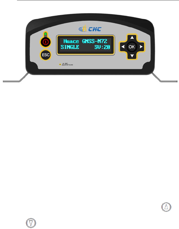
Thisisthemainreceiverscreen.
5.ConfiguringtheReceiver:KeypadandDisplay
N72GNSSReferenceReceiverUserGuidePage24
TheHomescreenshows:
Thenameoftheproduct.
Thepositionsolution.
Thenumberofsatellitesbeingtracked.
Asapower‐savingfeature,thefrontpanelgoesdarkafterashortperiodof
inactivity.Ifthedisplayisnotlitandthereceiverison,pressANYBUTTON
toreactivatethedisplay.
5.3. STATUSSCREENS
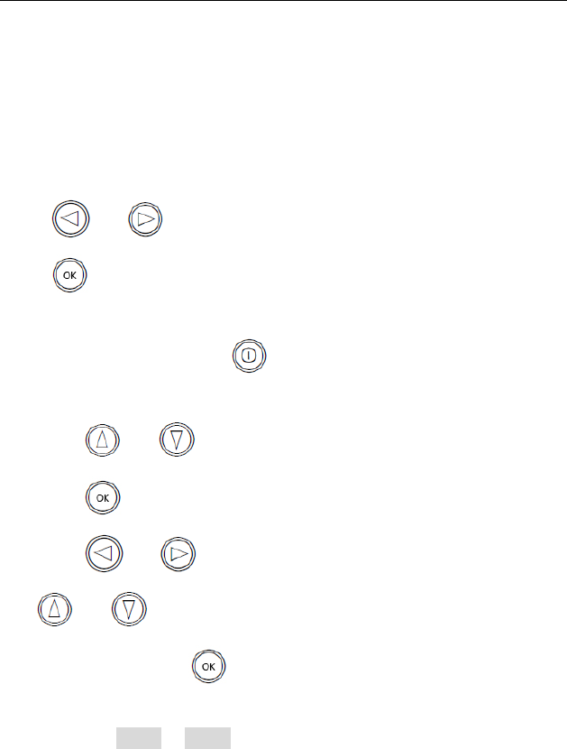
Toreviewthereceiver'scurrentsettingsinthestatusscreens,press
oronthefrontpanel.Thestatusscreensshowthefollowing
information:
CurrentNetworkconnectionstate
• CurrentIPaddress(editable)
• CurrentIPmask(editable)
• CurrentGateway(editable)
• CurrentDNSServer(editable)
• CurrentHTTPport(editable)
• Theinternalbatterypowerremaining
• Internalstoragememoryremaining
• Receiverhardwareversionandsoftwareversion
Receiverserialnumberandpartnumber
5.ConfiguringtheReceiver:KeypadandDisplay
N72GNSSReferenceReceiverUserGuidePage25
5.4. SETTINGUPTHERECEIVERASPARTOFANETHERNET
CONFIGURATION
UsethekeypadtosetupthereceiveraspartofanEthernetconfiguration.
Pressor tomovebetweendifferentstatusscreens,andthen
presstoentertheeditmode.
1. Turnonreceiverbypressorconnectthereceiverwithexternal
powersupply.
2. Pressor tomovetoIPAddrstatusscreen.
3. PresstoeditIPaddress.
4. Pressor toselectthecharactertoeditandthenpress
or tochangeit.
5. Whenfinished,press ,andthenthe“SettingSuccess”messagewill
appearonthedisplay.
6. Followthestep2tostep5toeditIPmask,gateway,DNSserverand
HTTPportintheIPMASK,Gateway,DNSServerandHTTPPORTstatus
screen,respectively.

N72GNSSReferenceReceiverUserGuidePage26
6. CONFIGURINGTHERECEIVER:OTHERTHAN
KEYPADANDDISPLAY
YoucanconfiguretheN72GNSSreferencereceivertoperformawidevariety
offunctions.Thischapterdescribestheconfigurationmethodsotherthan
thefrontpaneldisplay,andexplainswhenandwhyeachmethodisused.
TheWinFlashutilitydescribedinthischapterisusedprimarilytoupdatethe
receiverfirmware.
6.1. CONFIGURINGTHEETHERNETSETTINGS
ThereceiverEthernetportconnectstoanEthernetnetwork,throughwhich
youcanaccess,configure,andmonitorthereceiver.Noserialcable
connectiontothereceiverisnecessary.
ThereceiverhasthefollowingEthernetsettings:
• IPaddress
• IPmask
• Gateway
• DNSserver
• HTTPport
ThedefaultsettingfortheHTTPportis80:Thisportisnotassignedbythe
network.HTTPport80isthestandardportforwebserversandenablesyou
toconnecttothereceiverbyenteringonlythereceiver’sIPaddressinaweb
browser.
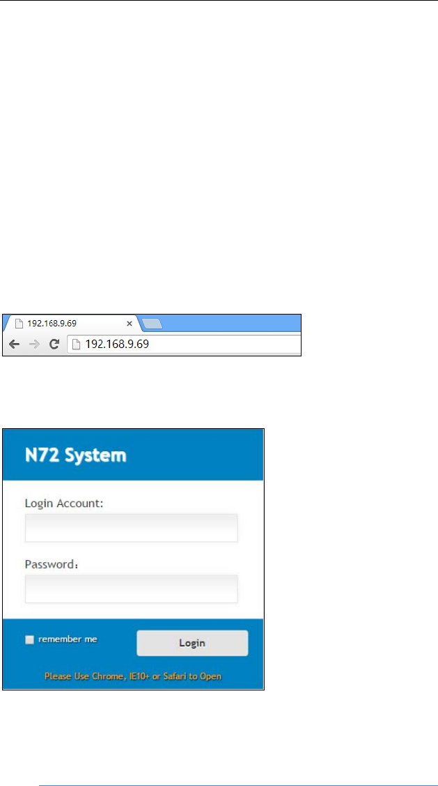
Forexample,usingport80:http://192.168.9.69
Ifthereceiverissettouseaportotherthan80,youmustentertheIP
addressfollowedbytheportnumberinawebbrowser.
Forexample,port9971:http://169.168.9.69:9971
UserscanconfiguretheEthernetsettingsthroughthefrontpanel(see5.4.
SettingupthereceiveraspartofanEthernetconfiguration)andaweb
server.Touseawebserver,thereceivermustbeconnectedtoanetwork
andhaveavalidEthernetconfiguration.
NOTE:ThereceivershouldbeconfiguredtheEthernetsettings
throughthefrontpanelforitsfirstconnectiontotheInternet.
6.ConfiguringtheReceiver:OtherThanKeypadandDisplay
N72GNSSReferenceReceiverUserGuidePage27
6.2. CONFIGURINGTHROUGHAWEBBROWSER
Supportedbrowsers:
GoogleChrome
MicrosoftInternetExplorer○
Rversion10,orhigher
AppleSafari
Toconnecttothereceiverthroughawebbrowser:
1. EntertheIPaddressofthereceiverintotheaddressbaroftheweb
browser:
2. Thewebbrowserpromptsyoutoenterausernameandpassword:
Thedefaultloginaccountforthereceiveris:
LoginAccount:admin
Password:password
NOTE:Tickremembermeoption,andthenthebrowserwill
remembertheLoginAccountandPasswordyouenteredforthenext
timeyouenterthisloginscreen.
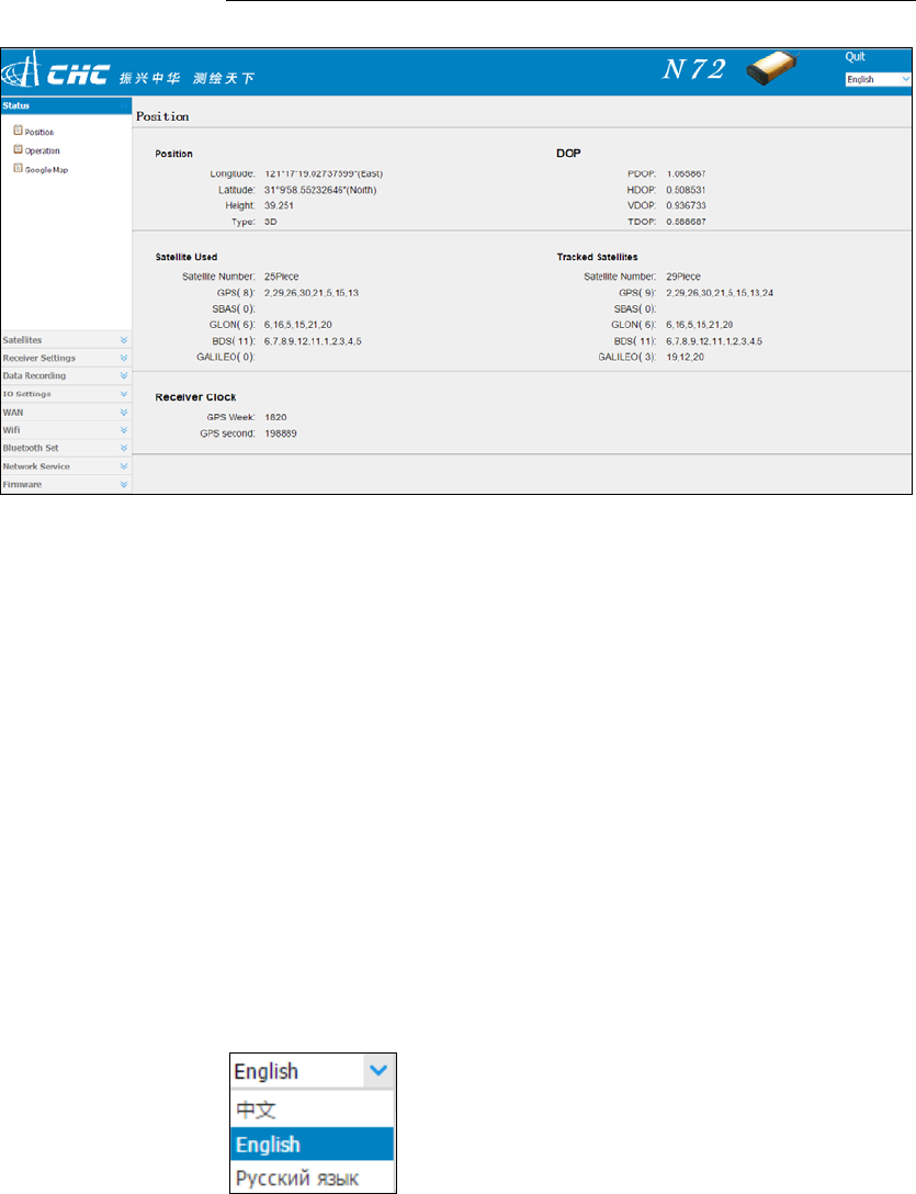
3. Onceyouareloggedin,thewebpageappearsasfollows:
6.ConfiguringtheReceiver:OtherThanKeypadandDisplay
N72GNSSReferenceReceiverUserGuidePage28
6.2.1. CHANGINGTHESETTINGS
Thewebinterfaceshowstheconfigurationmenusontheleftofthebrowser
window,andthesettingontheright.Eachconfigurationmenucontainsthe
relatedsubmenustoconfigurethereceiverandmonitorreceiver
performance.
Thissectiondescribeseachconfigurationmenu.
Toviewthewebinterfaceinanotherlanguage,selectthecorresponding
languagenamefromthedrop‐downlistintheupperrightcornerofthe
interface.
Currently,threelanguagesareavailable:
6.2.1.1. Statusmenu
Thismenuprovidesaquicklinktoreviewthereceiver'spositioninformation,
satellitestracked,runtime,currentdatalogstatus,currentoutputs,available
memory,andmore.
6.ConfiguringtheReceiver:OtherThanKeypadandDisplay
N72GNSSReferenceReceiverUserGuidePage29
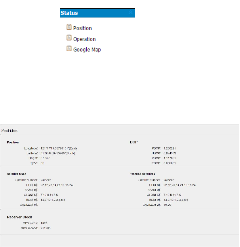
Position
Thispageshowstherelevantpositioninformationaboutthereceiver's
positionsolutionwhichincludingtheposition,DOPvalues,satellites
usedandtracked,andthereceiverclockinformation.
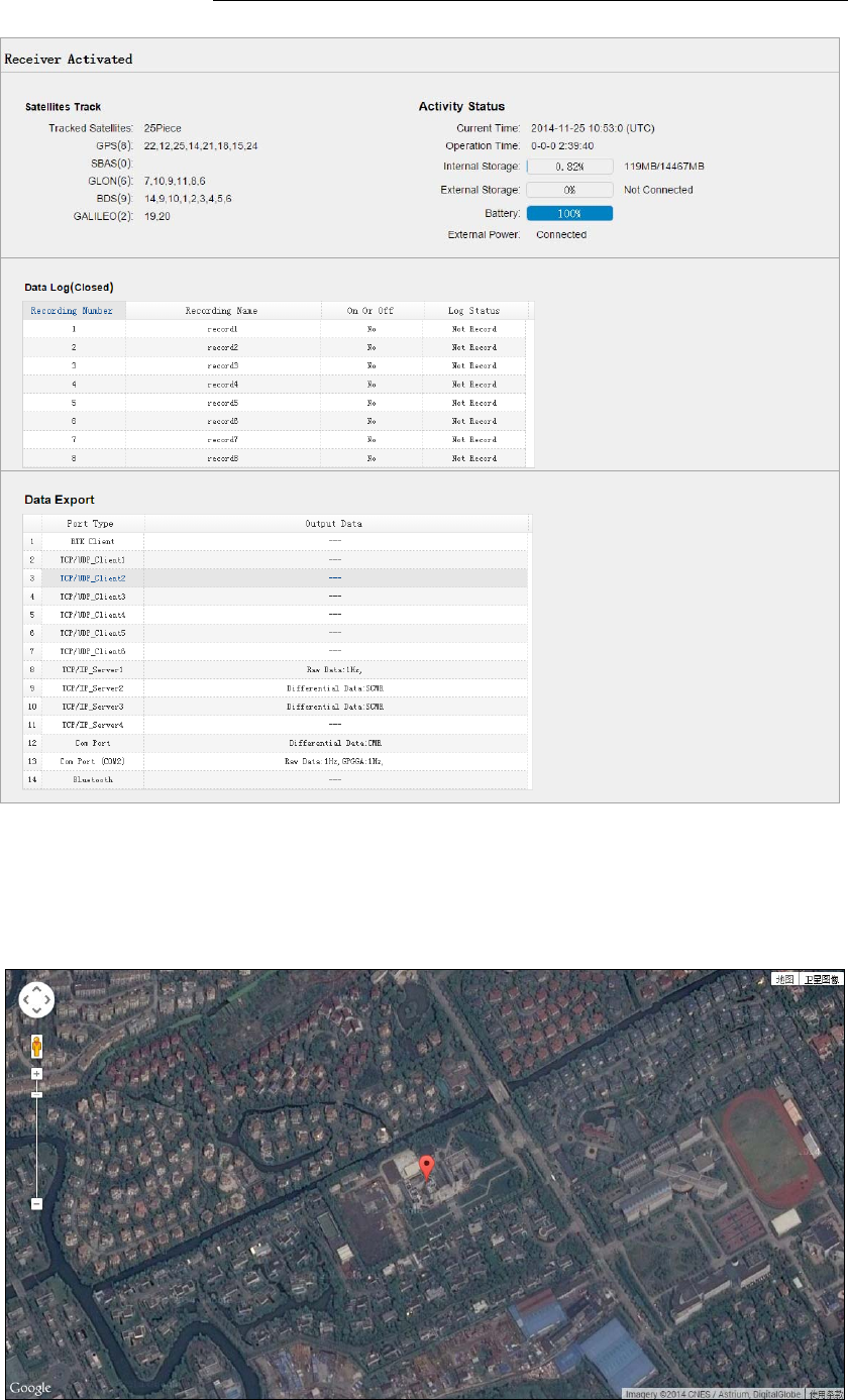
Operation
Listsseveralimportantitemstohelpyouunderstandhowthereceiveris
beingusedanditscurrentoperatingcondition.Itemsincludethe
identitiesofcurrentlytrackedsatellites,internalandexternalstorage
usagerate,howlongthereceiverhasbeenoperational,stateofthe
internalbattery,powersourcestate,filesbeinglogged,anddata
streamsbeingoutput.Withthisinformation,itiseasytotellexactly
whatfunctionsthereceiverisperforming:
6.ConfiguringtheReceiver:OtherThanKeypadandDisplay
N72GNSSReferenceReceiverUserGuidePage30
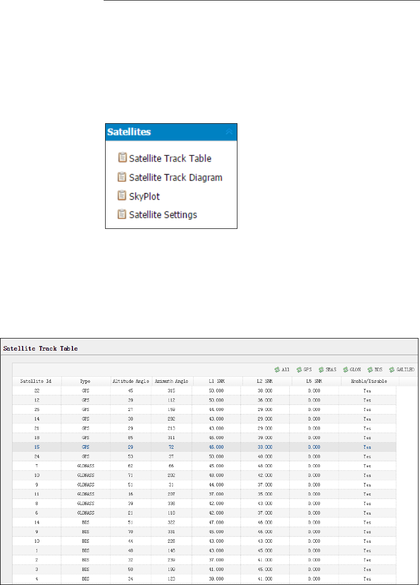
Googlemap
TapthissubmenutoshowthelocationofthereceiveronGooglemap.
6.ConfiguringtheReceiver:OtherThanKeypadandDisplay
N72GNSSReferenceReceiverUserGuidePage31
6.2.1.2. Satellitesmenu
UsetheSatellitesmenutoviewsatellitetrackingdetailsandenable/disable
GPS,SBAS,GLONASS,BDSandGalileoconstellations.Thesemenusinclude
tabularandgraphicaldisplaystoprovideallrequiredinformationonsatellite
trackingstatus.
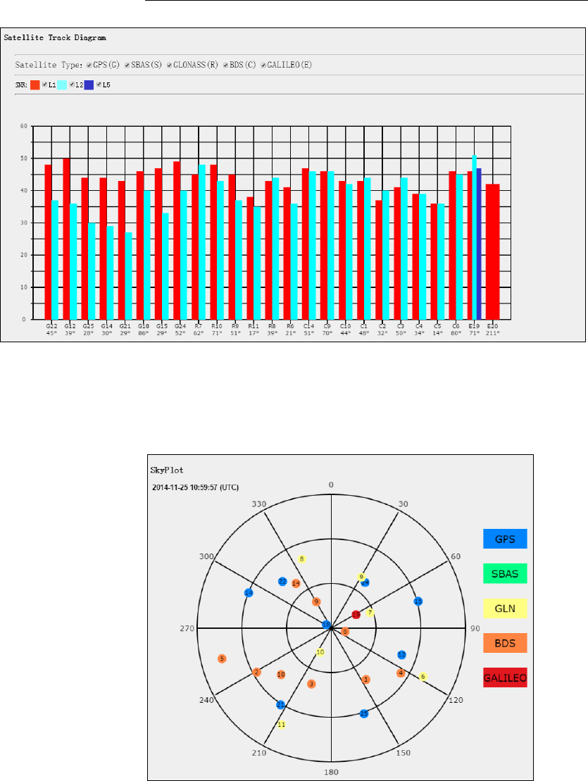
SatelliteTrackTable
Providesthestatusofsatellitestrackedingeneral,suchasthesatellite
ID,satellitetype,attitudeangle,azimuthangle,L1SNR,L2SNR,L5SNR
andenable/disablestatusofeachone.
SatelliteTrackDiagram
Thefollowingfigureisanexampleofsatellitetrackdiagrampage.Users
candeterminethesatellitetypesandthecorrespondingSNRofL‐band
carrierstobedisplayedinanycombination.
6.ConfiguringtheReceiver:OtherThanKeypadandDisplay
N72GNSSReferenceReceiverUserGuidePage32
SkyPlot
ThefollowingfigureisanexampleofSkyplotpage.
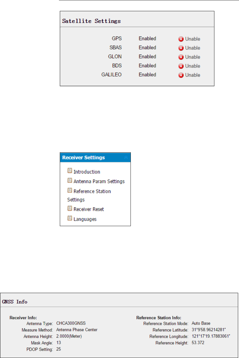
SatelliteSettings
Inthissubmenu,userscanenable/disableGPS,SBAS,GLONASS,BDS
andGalileoconstellations.
6.ConfiguringtheReceiver:OtherThanKeypadandDisplay
N72GNSSReferenceReceiverUserGuidePage33
6.2.1.3. ReceiverSettingsmenu
Usethismenutoconfiguresettingssuchastheantennatypeandheight,
elevationmaskandPDOPsetting,thereferencestationcoordinates,receiver
resettingandwebinterfacelanguage:
Introduction
Thissubmenushowsthereceiverinformationandreferencestation
information,includingantennarelatedinformation,elevationmask
angle,referencestationworkmodeandposition,etc.
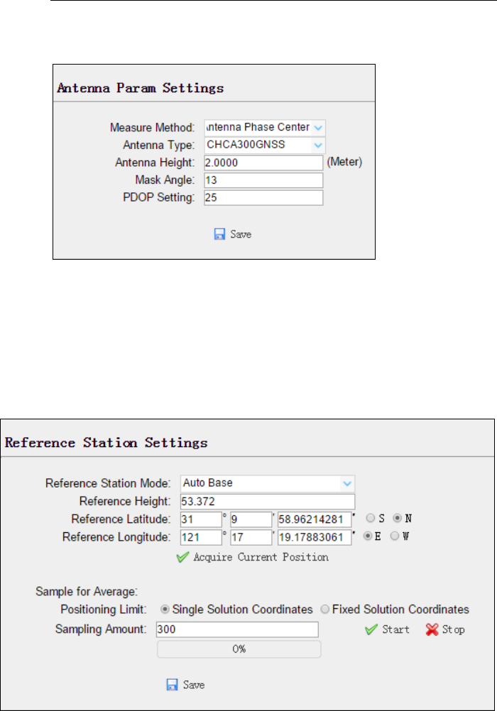
AntennaParamSettings
UsethisscreentoconfigurealloftheitemsrelatingtotheGNSS
antenna.Youmustenterthecorrectvaluesforallantenna‐relatedfields,
asthechoicesyoumakesignificantlyaffecttheaccuracyforloggeddata
6.ConfiguringtheReceiver:OtherThanKeypadandDisplay
N72GNSSReferenceReceiverUserGuidePage34
andbroadcastRTKcorrectors:
ReferenceStationSettings
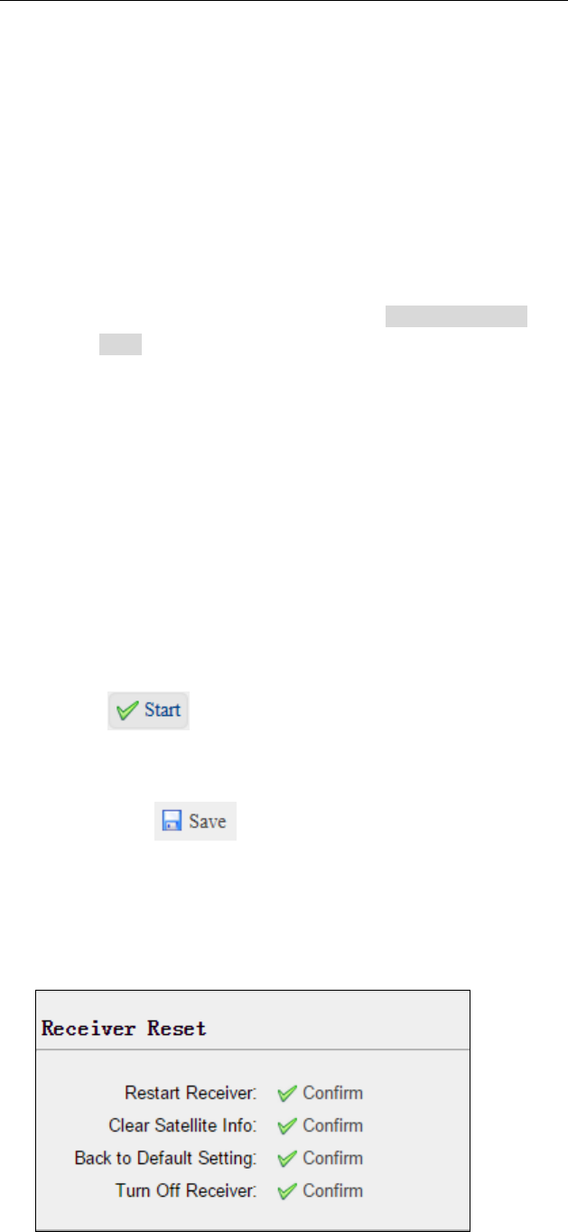
Usethisscreentoconfiguresettingssuchasthestationcoordinates.You
mustenteraccurateinformationinthesefields,asthisdatasignificantly
affectstheaccuracyofloggeddatafilesandbroadcastRTKcorrectors.
ForReferenceStationMode:
Therearethreeavailableoptions:AutoRover,AutoBaseand
ManualBase.
AutoRover:ThereceiverwillserveasRoveraftertherestart.
AutoBase:ThereceiverwillserveasBaseaftertherestart,and
thenbroadcastRTKcorrectorsbasedoncoordinatesobtained
throughsingle‐pointpositioningautomatically.
ManualBase:ThereceiverwillserveasBaseaftertherestart,
andthenbroadcastRTKcorrectorsbasedonthecoordinates
beforepoweroff.
6.ConfiguringtheReceiver:OtherThanKeypadandDisplay
N72GNSSReferenceReceiverUserGuidePage35
ForReferenceLatitudeandReferenceLongitude:
Therearemainlythreemethodstoenterthereferencecoordinates
andshownasfollows:
AcquireCurrentPosition:Clickthisbuttontoacquirecurrent
positionobtainedthroughsingle‐pointpositioning
automatically.
ManualInput:Manuallyinputaknowncoordinates.
FromCORS:AfterlogginginCORS,thereceiverwillobtaina
coordinatesbasedonfixsolution.(See6.2.1.5.IOSettings
menuformoredetailsaboutlogginginCORS.)
ForSampleforAverage:
Userscandeterminethepositioninglimitandsamplingamount.
Thepositioninglimitfallsintotwotypes:
SingleSolutionCoordinates:Collectthecoordinatesofreceiver
obtainedthroughsingle‐pointpositioning.
FixedSolutionCoordinates:Onlycollectcoordinatesof
receiverbasedonfixsolution.
Aftertheconfigurationofpositioninglimitandsamplingamount,
clicktocarryoutsamplingandaveragingtheresult
willbeservedasthecoordinatesofcurrentpositon.
Also,userscanclicktosavethecurentsettings.
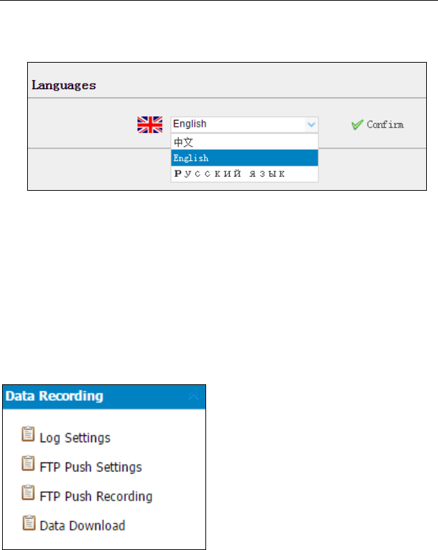
ReceiverReset
Usethisscreentocompletelyorpartiallyresetthereceiver:
Languages
6.ConfiguringtheReceiver:OtherThanKeypadandDisplay
N72GNSSReferenceReceiverUserGuidePage36
Usethisscreentoselectthewebinterfacelanguage:
6.2.1.4. DataRecordingmenu
UsetheDataLoggingmenutosetupthereceivertologstaticGNSSdataand
toviewtheloggingsettings.Youcanconfiguresettingssuchasobservable
rate,recordingrate,continuouslogginglimit,andwhethertoautodeleteold
filesifmemoryislow.ThismenualsoprovidesthecontrolsfortheFTPpush
feature:
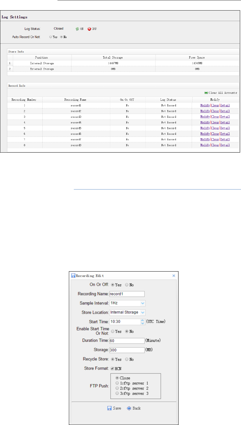
LogSettings
Showsthedataloggingstatus,internalandexternalstorageusageand
dataloggingstatusofeachstoragethread.Also,userscanconfigurethe
dataloggingsettingsforeachstoragethread,includingrecordingname,
savinglocation,storagelimit,storeformats,starttime,etc.
6.ConfiguringtheReceiver:OtherThanKeypadandDisplay
N72GNSSReferenceReceiverUserGuidePage37
Toopenorcloseallthestoragethreads,clickthe[ON]or[OFF]button
totherightofLogStatusfield.
NOTE–The[ON]and[OFF]buttontotherightofLogStatusfieldare
theMasterLogSwitch.Everystoragethreadcanlogdataonlywhen
theMasterLogSwitchisON.Anduserscaneditthesettingsof
storagethreadsonlywhentheMasterLogSwitchisOFF.
Toeditthesettingsofeachstoragethread,clickthe[Modify]buttonto
therightoftherequiredstoragethread,andthentheRecordingEdit
screenappears:

6.ConfiguringtheReceiver:OtherThanKeypadandDisplay
N72GNSSReferenceReceiverUserGuidePage38
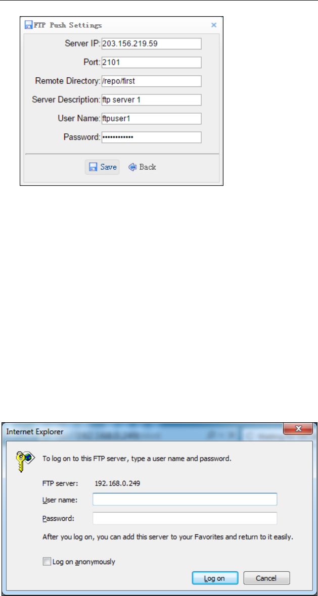
Inthisscreen,youcansetalldataloggingparameters,and
determinewhethertherecordingfileswillbeaffectedbytheFTP
Push.Theparametersaremainlyasfollows:
OnorOff:Select“Yes”or“No”todeterminewhethertolog
datawhentheMasterLogSwitchisON.
RecordingName:Thenameofthisstoragethread.
SampleInterval:Selecttheobservableratefromthedropdown
list.
StoreLocation:Determinewhethertostoreatinternalstorage
orexternalstorage.
StartTime:SetthestarttimeofdataloginUTC.Select“Yes”or
“No”optionbelowtodeterminewhethertostartloggingfrom
thesettime.
DurationTime:Setthetimeintervalofrecording.
Storage:Setthestoragelimitofthisthread.
RecycleStorage:Select“Yes”or“No”todeterminewhetherto
autodeleteoldfilesifthestoragespaceisfull.
StorageFormat:ThedefaultformatofrecordingfilesisHCN.
FTPPush:DecidewhethertopushthestoredfilestotheFTP
serverofyourchoice.
ClicktosavethesettingsandbacktotheLogSettings
screen.Also,userscanclicktoabandonthechanged
settingsandbacktoLogSettingsscreen.
NOTE–todeletetherecorddata,youcanremovealltheeightrecord
databythetotalbuttonclearallaccounts.Alsoyoucandeleteeach
recorddatabyclearbuttonundertheselectedthread.
TodeletetherecordedfilesofANYstoragethread,clickthe[Clear]
buttontotherightoftherequiredstoragethread.
TodeletetherecordedfilesofALLstoragethreads,click[ClearAll
Accounts]button.
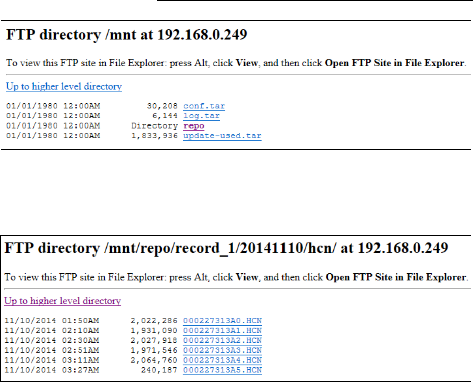
FTPPushSettings
UsethisscreentoconfigurethereceivertopushstoredfilestotheFTP
serverofyourchoice.OnlyfilesthatareconfiguredtouseFTPpushare
transmitted.Click[Modify]buttontotherightoftherequiredFTP
serverandtheFTPPushSettingsscreenappears:
6.ConfiguringtheReceiver:OtherThanKeypadandDisplay
N72GNSSReferenceReceiverUserGuidePage39
FTPPushRecording
Showstherelatedinformationabouttherecordedfiledthatbepushed.
Anduserscanclick[ClearFtpSendLog]buttonintheupperrightcorner
toclearthestatusofFTPPushoperations.
DataDownload
Inthissubmenu,userscandownloadthedatafilesthatrecordedinthe
internalstoragethroughtheinternalFTPsite.
1. Clickthissubmenu,andthenthelogondialogueboxwillprompt
youtoenterausernameandpassword:
ThedefaultlogonaccountfortheinternalFTPsiteis:
Username:ftp
Password:ftp
2. Clickthedirectorynamedasrepotoviewanddownloadthefiles
currentlystoredonthereceiver:
6.ConfiguringtheReceiver:OtherThanKeypadandDisplay
N72GNSSReferenceReceiverUserGuidePage40
3. Tofindthefileneedtobedownloaded,clickthenameofstorage
threadthedateoffilethatberecordedtheformatofthefile
thenameofthetargetfile.
4. Todownloadafile,left‐clickthenameofthetargetfile
downloadthefileaccordingtotheprompts.
6.2.1.5. IOSettingsmenu
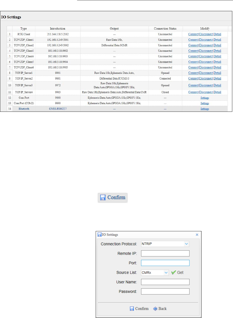
UsetheIOSettingsmenutosetupallreceiveroutputsandinputs.The
receivercanoutputCMR,RTCM,Rawdata,Ephemerisdata,GPGGA,GPGSV,
onTCP/IP,UDP,serialport,orBluetoothports.
IOSettings
Thefollowingfigureshowsanexampleofthescreenthatappearswhen
youselectthissubmenu.
6.ConfiguringtheReceiver:OtherThanKeypadandDisplay
N72GNSSReferenceReceiverUserGuidePage41
Inthissubmenu,userscanconfigure5typesofinputandoutput
settings.
1. RTKClient
AfterconfiguringthesettingsofRTKclient,userscanlogonCORSor
APIS.Clickthe[Connect]buttontotherighttheIOSettingsscreen
willappearchooseoneoftheconnectionprotocolsamongtheNTRIP,
APIS_BASEandAPIS_ROVERconfiguretherelatedparameters
clicktologonCORSorAPIS.
ConnectionProtocol:NTRIP
ConnectionProtocol:APIS_BASE
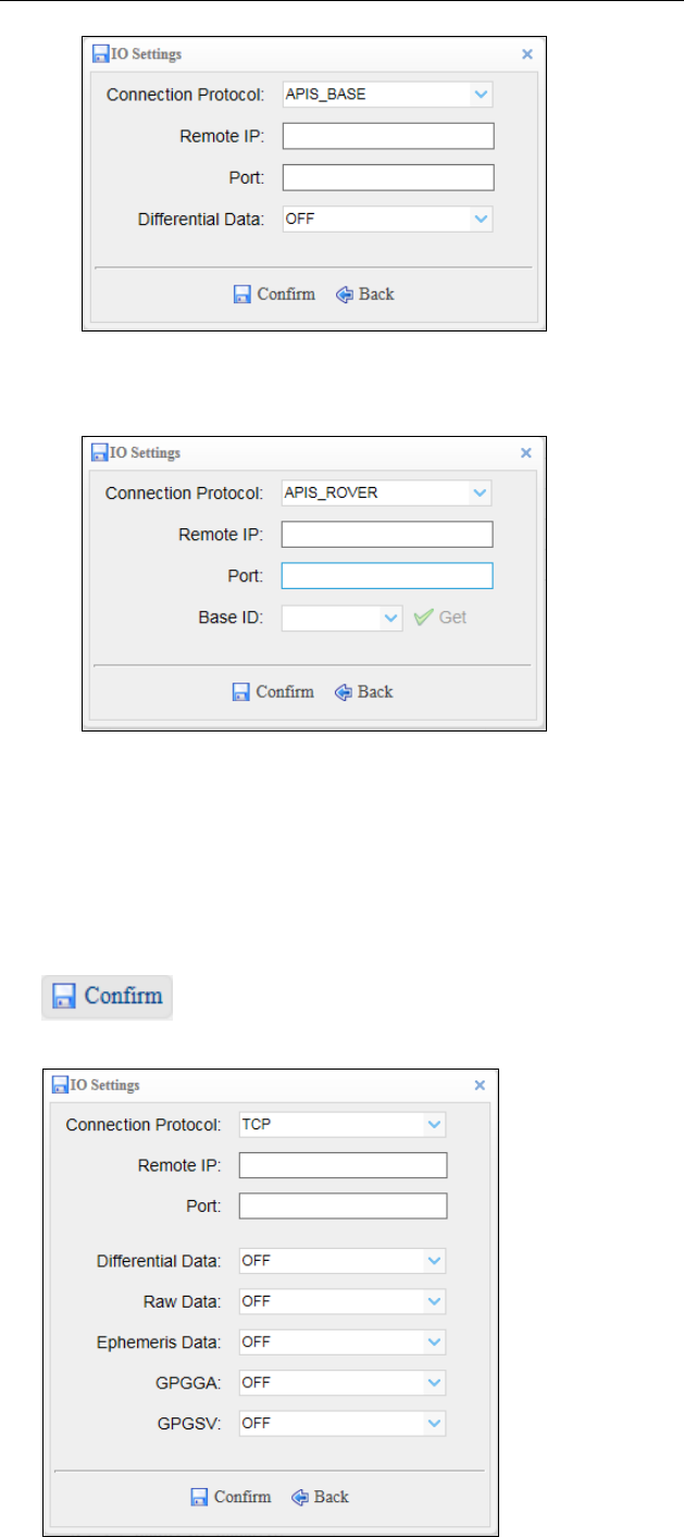
6.ConfiguringtheReceiver:OtherThanKeypadandDisplay
N72GNSSReferenceReceiverUserGuidePage42
ConnectionProtocol:APIS_ROVER
2. TCP/UDPClient
Clickthe[Connect]buttontotherightofrequiredTCP/UDPClient
theIOSettingsscreenwillappearselecttheconnectionprotocol
fromthedropdownlistentertheIPandPortofthetargetserver
configuremessagesthatyouwanttooutputtothetargetserverclick
tosaveandcompletetheconnection.
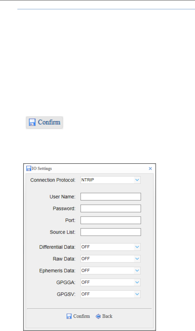
6.ConfiguringtheReceiver:OtherThanKeypadandDisplay
N72GNSSReferenceReceiverUserGuidePage43
NOTE:IfthereceiverandserverareunderthesameLocalArea
Network(LAN),userscanusetheIPaddressinLANoftheserverwith
anyPort.However,ifthereceiverandserverareunderthetwo
differentLAN,usersshouldusethepublicIPaddressoftheserver
andconfiguretheportmappingoftheserver.
3. TCP/IPServer
Clickthe[Connect]buttontotherightofrequiredTCP/IPServerthe
IOSettingsscreenwillappearselectoneoftheconnectionprotocols
betweenNTRIPandTCPconfiguretheotherrelatedparameters
clicktosavethesettingsandopentheserver.
ConnectionProtocol:NTRIP
ConnectionProtocol:TCP
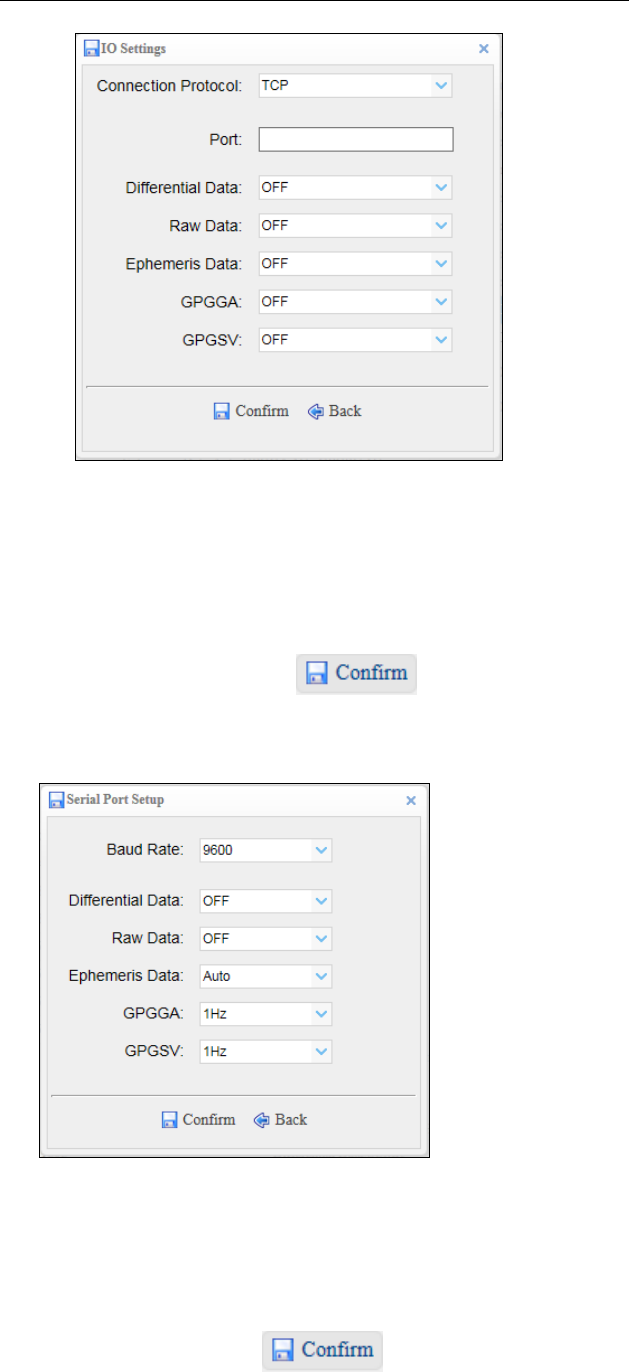
6.ConfiguringtheReceiver:OtherThanKeypadandDisplay
N72GNSSReferenceReceiverUserGuidePage44
4. COMPort
Clickthe[Settings]buttontotherightofrequiredCOMPortthe
SerialPortSetupscreenwillappearselectBaudRateusedto
transmitdataconfigurethemessagesthatyouwanttooutput
throughtheserialportclicktosavethesettingsand
starttotransmit.
5. Bluetooth
Clickthe[Settings]buttontotherightofBluetooththeBluetoothSet
screenwillappearconfigurethemessagesthatyouwanttotransmit
throughBluetoothclicktosavethesettingsandstart
totransmit.
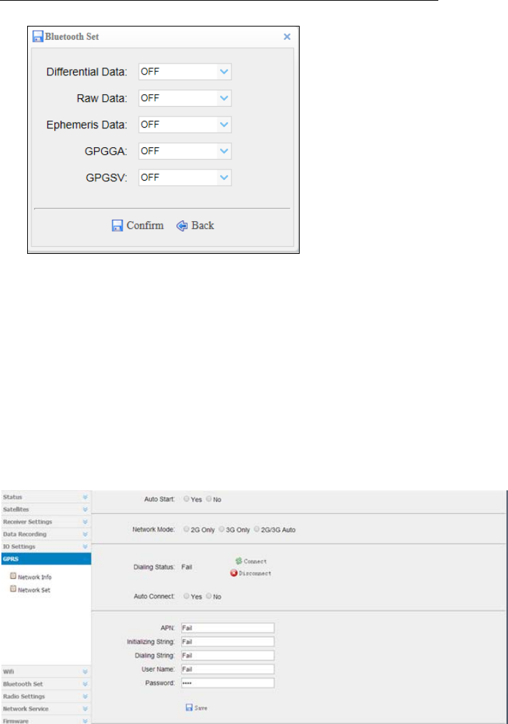
6.ConfiguringtheReceiver:OtherThanKeypadandDisplay
N72GNSSReferenceReceiverUserGuidePage45
6.2.1.6. GPRSmenu
NetworkInfo:networkinfoshowspowerstatus,networkmode,connection
protocol,signalstrength,SIMstatusanddialingstatus.
Networkset:mainlytosetGPRSmodelstatus,autostart,networkmode
(generallyusersselect[2G/3GAuto]),parametersettingsandsoon.
6.2.1.7. Radiosettingmenu
RadioInfo:showsradiotype,radiopower,OTAbaudrate,radiofrequency
andsoon.
Radiosetting:tosetradiostatus,autostart,radiopower,frequencyandso
on.Whenusingwebpagesettingaloneandtheradiofunctionisrequired,
usersneedtoturnonRadioStatusandAutoStart.IftheradioinIOsettingis
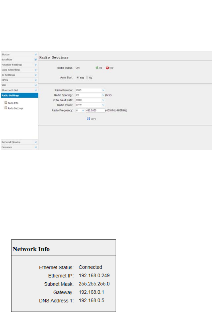
6.ConfiguringtheReceiver:OtherThanKeypadandDisplay
N72GNSSReferenceReceiverUserGuidePage46
requiredtobeused,thepremisesarealsoturningonradiostatus,setting
appropriatefrequency,powerandsoon.
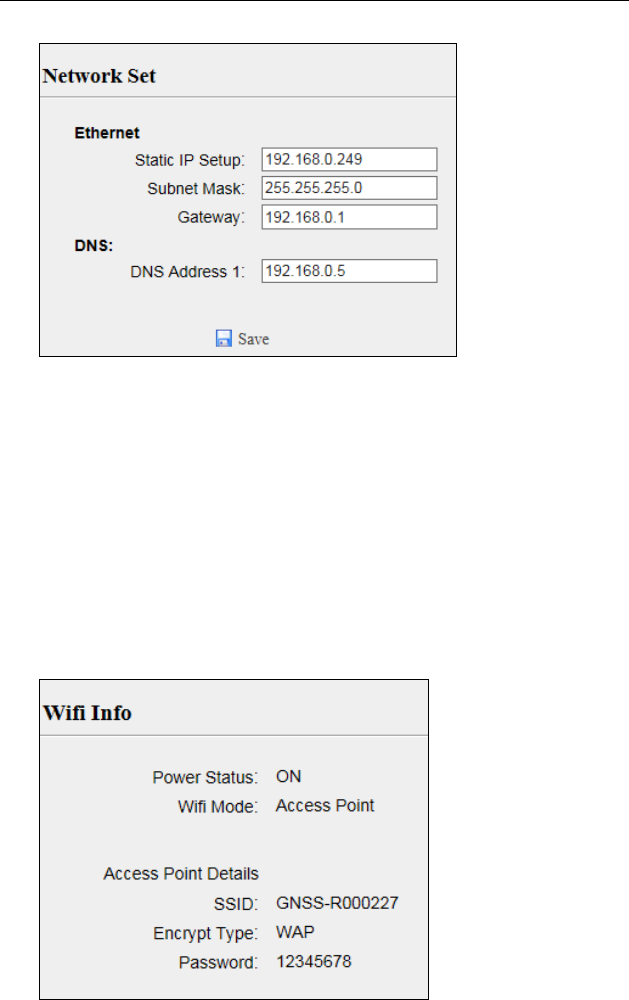
6.2.1.8. WANmenu
UsethismenutocheckandconfiguretheEthernetsettings.
NetworkInfo
Thefollowingfigureshowsanexampleofthescreenthatappearswhen
youselectthissubmenu:
NetworkSet
UsethissubmenutoconfiguretherelatedparametersoftheNetwork,
includingstaticIP,subnetmask,etc.
6.ConfiguringtheReceiver:OtherThanKeypadandDisplay
N72GNSSReferenceReceiverUserGuidePage47
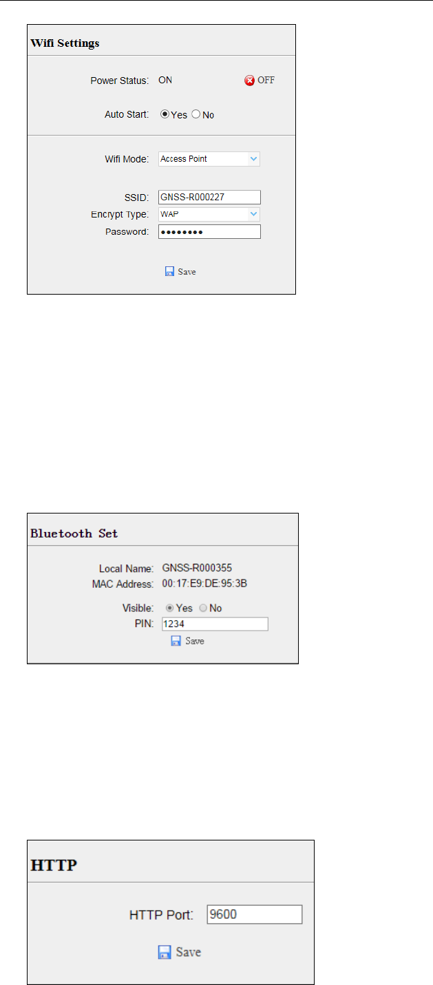
6.2.1.9. Wifimenu
UsethismenutocheckandconfiguretheWifisettings.
WifiInfo
Thefollowingfigureshowsanexampleofthescreenthatappearswhen
youselectthissubmenu:
WifiSettings
UsethissubmenutoconfiguretherelatedparametersoftheWi‐Fi
settings,includingWi‐Fimode,encrypttype,password,etc.
6.ConfiguringtheReceiver:OtherThanKeypadandDisplay
N72GNSSReferenceReceiverUserGuidePage48
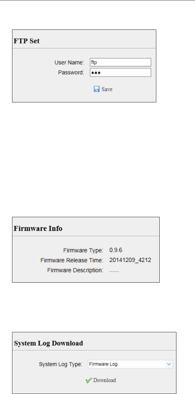
6.2.1.10. BluetoothSetmenu
UsethismenutoconfigureBluetoothsettings.
BluetoothSet
Thefollowingfigureshowsanexampleofthescreenthatappearswhen
youselectthissubmenu:
6.2.1.11. NetworkServicemenu
Usethismenutoconfigurethereceiver’sHTTPport,andtheusernameand
passwordofinternalFTPsite.
HTTP
6.ConfiguringtheReceiver:OtherThanKeypadandDisplay
N72GNSSReferenceReceiverUserGuidePage49
FTPService
6.2.1.12. Firmwaremenu
Usethismenutocheckthecurrentfirmwareinformation,downloadthe
systemlog,updatethereceiverfirmware,downloadorupdatethe
configurationfileandregisterthereceiver.
FirmwareInfo
Usethissubmenutocheckthecurrentfirmwareinformation.The
followingfigureshowsanexampleofthefirmwareinformation.
SystemLog
Usethissubmenutodownloadthesystemlogofthereceiver.
FirmwareUpdate
Usethissubmenutoloadnewfirmwaretothereceiveracrossthe
network.Clickthe[Browse]buttontolocatetheupgradefileclick
[Confirm]buttontoconfirmtheselectedupgradingfileandstart
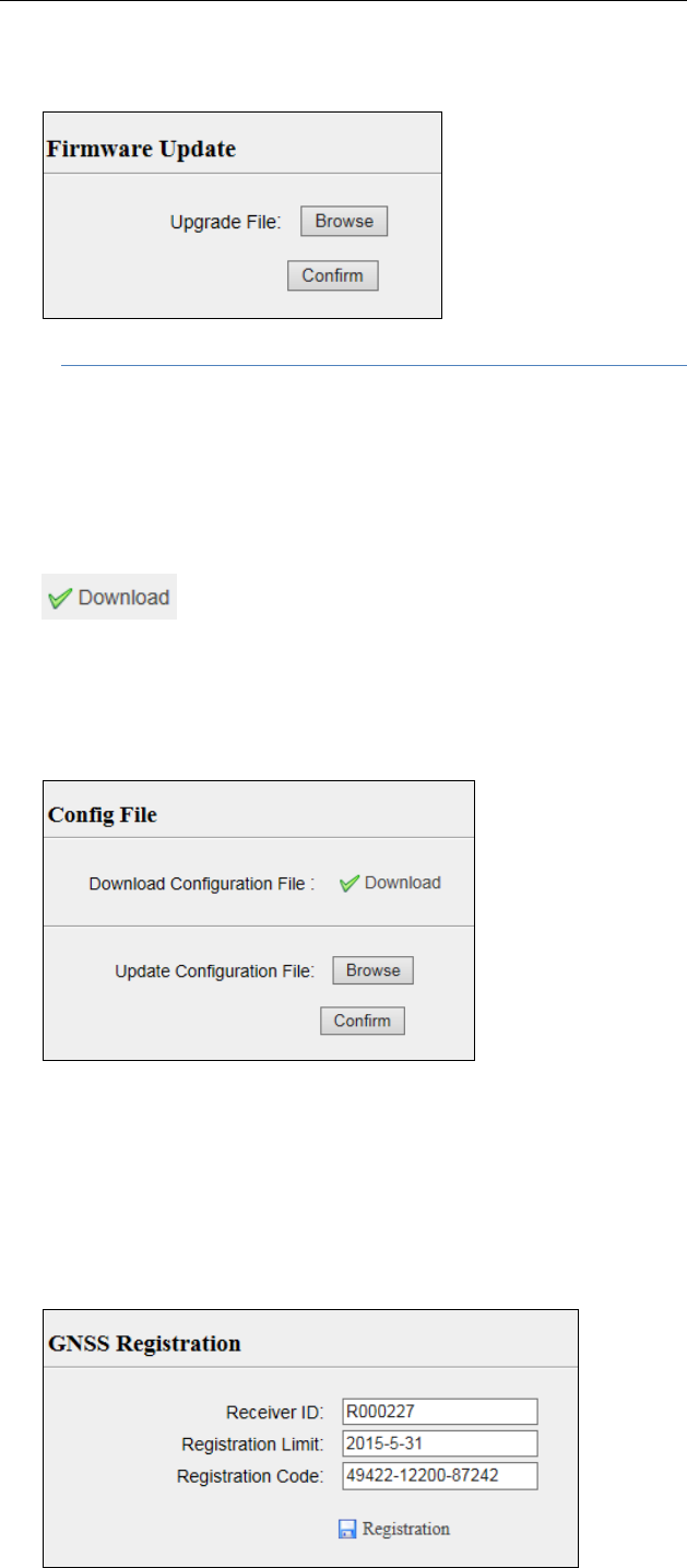
6.ConfiguringtheReceiver:OtherThanKeypadandDisplay
N72GNSSReferenceReceiverUserGuidePage50
upgrading.
NOTE:Itwilltakeabout2or3minutestocompletethefirmware
upgrading.
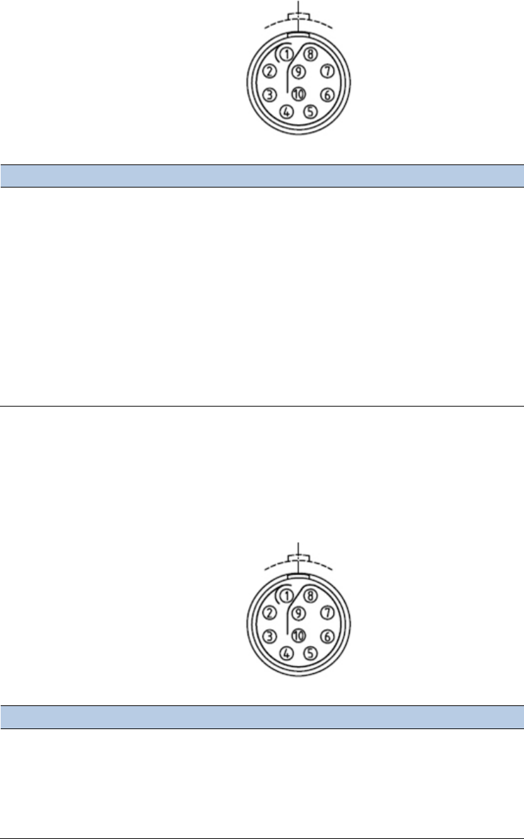
ConfigFile
Inthissubmenu,userscandownloadtheconfigurationfilebyclicking
buttonanddetermineasavingpathtodownloadthe
configurationfile(.cfgfile).Also,userscanclickthe[Browse]buttonto
locatetheexistingconfigurationfileclick[Confirm]buttontoconfirm
theselectedfileandstartupdating.
GNSSRegistration
Usethissubmenutoregisterthereceiver.Pasteorentertheregistration
codetotheRegistrationCodefieldclick[Registration]buttonto
completetheregistration.

6.ConfiguringtheReceiver:OtherThanKeypadandDisplay
N72GNSSReferenceReceiverUserGuidePage51

N72GNSSReferenceReceiverUserGuidePage52
7. DEFAULTSETTINGANDCONFIGURATIONFILES
Mostofthereceiversettingsarestoredinapplicationfiles.Thedefault
applicationfile,Default.cfg,isstoredpermanentlyinthereceiver,and
containsthefactorydefaultsettingsfortheN72GNSSreferencereceiver.
Wheneverthereceiverisresettoitsfactorydefaults,thecurrentsettings
(storedinthecurrentconfigurationfile,copy.cfg)areresettothevaluesin
thedefaultapplicationfile.
TheN72GNSSreferencereceiverextendstheuseofconfigurationfilesto
allowsimplifiedreceiversettingduplicationinmultiplereceivers.Thisis
sometimesreferredtoasreceivercloningandisveryusefulwhenpreparing
alargegroupofreceiversforafielddatacollectioncampaign.
7.1. DEFAULTRECEIVERSETTINGS
Function Factorydefaultvalues
SVEnable AllSVsenabled
GeneralcontrolsElevationmask
PDOPmask
0°
6°
LemoportBaudrate
Format
Flowcontrol
9600
8‐None‐1
None
DB9portBaudrate
Format
Flowcontrol
9600
8‐None‐1
None
Logstatus OFF
Differentialdata OFF
Rawdata OFF
Ephemerisdata OFF
NMEA(GPGGA,GPGSV) OFF
ReferencepositionLatitude
Longitude
Height
0°0’0.00000000’’
0°0’0.00000000’’
0.000
AntennaType
MeasureMethod
Height
CHCA300GNSS
2.0000(Meter)
AntennaPhaseCenter
7.1.1. RESETTINGTHERECEIVERTOFACTORYDEFAULTS
LoginthewebpageofthereceivertapandunfoldtheReceiverReset
menutaptheReceiverResetsubmenuclickthe
buttontotherightofBacktoDefaultSettingfield.
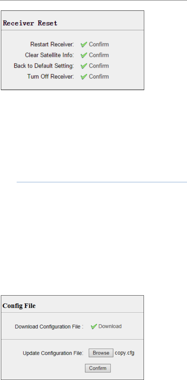
7.DefaultSettingsandApplicationFiles
N72GNSSReferenceReceiverUserGuidePage53
7.1.2. USINGCONFIGURATIONFILESTODUPLICATERECEIVERSETTINGS
TheN72GNSSreferencereceiverallowstheextensiveuseofapplicationfiles
inordertoretainauniquereceiverconfiguration.Withthisreceiver,youcan
createaconfigurationfilethatincludesmostofthereceiver'sunique
configurationsettings.Youcanthenupdatethatconfigurationfileontoone
ormoreotherN72GNSSreferencereceiverstoquicklyconfigurethemto
matchthereceiverwhichcreatesthatconfigurationfile.
NOTE:Theconfigurationfileincludesmostoftheconfiguration
settingsexceptIPAddress,IPMask,GatewayandDNSServer.
Thisiscalledreceiverconfigurationcloningorcloning.Receivercloning
greatlyreducesthetimerequiredtopreparealargegroupofreceiversfor
fieldoperations.
LoginthewebpageofthereceivertapandunfoldtheFirmwaremenu
taptheConfigFilesubmenuclickthe[Browse]buttontolocatethe
existingconfigurationfileclick[Confirm]buttontoconfirmtheselected
fileandstartupdating.

N72GNSSReferenceReceiverUserGuidePage54
8. SPECIFICATIONS
ThischapterdescribesthespecificationsfortheN72GNSSreferencereceiver.
Specificationsaresubjecttochangewithoutnotice.
8.1. GNSSCHARACTERISTICS
Feature Specification
Tracking 220channels
– GPS:L1C/A,L2C,L2E,L5
– GLONASS:L1C/A,L1P,L2C/A,L2P
– SBAS:WAAS,EGNOS,MSAS
– Galileo:E1,E5A,E5B
– BDS:B1,B2
Pseudo‐rangemeasurementwithhigh‐precision
multi‐correlator
Verylownoisecarrierphasemeasurementswith<1mm
precisionina1Hzbandwidth
RealTimeKinematic(RTK)Horizontal:8mm+1ppmRMS
Vertical:15mm+1ppmRMS
PostProcessingStaticHorizontal:2.5mm+0.5ppmRMS
Vertical:5mm+0.5ppmRMS
InitializationtimeTypically<10s
InitializationreliabilityTypically>99.9%
8.2. COMMUNICATION
FeatureSpecification
RJ45JackEthernet
DB9male3‐wireRS232,seeC.I.CHCN72receiverCOM1(10‐pinLEMOport)
definitionfordetails
COM1(10‐pinLEMOport)8‐wireRS232,seeC.II.CHCN72receiverCOM2(10‐pinLEMOport)
definitionfordetails
COM2(10‐pinLEMOport)9‐wireRS232,seeC.III.CHCN72receiverdb9maleconnector
definitionfordetails
USBportType‐AUSBreceptacle,operatesinHostmode
BluetoothFullyintegrated,fullysealed2.4GHzBluetoothwirelesstechnology
ProtocolsCorrectionformats:CMR,CMR+,SCMR,RTCM2.3,3.0
Observables:RT17,RT27,RTCM3.X
Position/StatusI/O:NMEA‐0183V2.30(GPGGA&GPGSV)

8.Specifications
N72GNSSReferenceReceiverUserGuidePage55
8.3. PHYSICAL
Feature Specification
Size265x143x68mm(10.4x5.6x2.7in)
Weight2.1kg(74oz)
Operatingtemperature
Storagetemperature
‐40°Cto+65°C(‐40°Fto+149°F)
‐45°Cto+80°C(‐49°Fto+176°F)
Humidity100%condensation
Waterproofanddust
proof
TestedtoIP67;waterprooffortemporaryimmersiontoadepthof1m
(3.28ft)for30minutes;dustproof
ShockDesignedtosurvivea1m(3.28ft)dropontoconcrete
8.4. ELECTRICAL
Feature Specification
Powerconsumption4Wnominal,dependentonusersettings
Internal Integratedinternalbattery7.4V,10000mA‐hr,Lithium‐ion
InternalbatterycanoperateasaUPSintheeventofexternal
powersourceoutage
Internalbatterywillchargefromtheexternalpowersourcewhen
theinternalbatteryisnotfullycharged
External Powersourcesupply(Internal/External)ishotswapcapableinthe
eventofpowersourceremovalorcut‐off
PowerinputonLemoportsis12VDCto36VDCexternalpower
input
Receiverwillautopoweronwhenconnectedtoexternalpower
withvoltageabove11V
Operationtimeon
internalbattery
Upto17hourscontinuousoperation,dependentonusersetting
8.5. GENERAL
Feature Specification
Frontpaneldisplay VacuumFluorescentDisplay(VFD),16charactersby2rows
PowerbuttonandindicationLED
Escape,OKand4arrowkeys(up,down,left,right)
Receivertype GNSSreferencereceiver
Antennatype CHCA220GRGNSSGeodeticantennaorCHCC220GRGNSSChoke
Ringantennapreferred.
Othermodelssupported.

8.Specifications
N72GNSSReferenceReceiverUserGuidePage56
8.6. DATASTORAGE
FeatureSpecification
Internalstorage16GB
ExternalstorageSupportingUSBdriveorportableharddrive
Storagemethod8‐threadlogging,circulatingdatalogging
DataformatHCN,RINEX,originalbinarydata
DatadownloadFTPpush,onlinedownload,storageonanexternalUSBdevices
N72GNSSReferenceReceiverUserGuidePage57
A. UPGRADINGTHERECEIVERFIRMWARE
Thereceiverissuppliedwiththelatestversionofthereceiverfirmware
alreadyinstalled.Ifalaterversionofthefirmwarebecomesavailable,use
theUSBdevicetoupgradethefirmwareonyourreceiver.Forthelatest
firmwareresource,pleaseconsultyourlocalCHCdealer.
Youcanalsoupgradethereceiverthroughthewebinterface.Thefirmware
filerequiredtoupgradethereceiverthroughtheWebinterfaceislocatedin
thefolderwheretheusersavesthefile.Thefiletyperequiredistheformat
update_n72_e_vXXXXX_bYYYYMMDD.binwhereXXXXXrepresentsthe
versionoffirmwareandYYYYMMDDrepresentsthefirmwareencapsulation
date.
A.I. THEWINFLASHUTILITY
TheWinFlashutilitycommunicateswithCHCproductstoperformvarious
functionsincluding:
loadorverifyGPSsoftwareofthemainboard
updateorverifythereceiveroptions
Formoreinformation,onlinehelpisalsoavailablewhenusingtheWinFlash
utility.
A.I.i. INSTALLINGTHEWINFLASHUTILITY
YoucandownloadtheWinFlashutilityfromtheTrimblewebsite.This
self‐extractingexecutableguidesyouthroughthesoftwareinstallation
process.
A.II. UPGRADINGTHERECEIVERFIRMWARE
A.II.i. UPGRADINGTHROUGHUSBPORT
1. Copythefirmwarefiletotherootdirectoryofexternalstoragedevice
suchasUSBdrive,portableharddrive.
2. ConnecttheexternalstoragedevicewithreceiverthroughUSBport.
3. Restartthereceiverandthenthescreenwillpromptyouwhetherto
upgradethefirmware.
4. PressOKbuttontoupgradethefirmware.
5. Whentheupgradingiscompleted,thereceiverwillberestartedand
thescreenwillpromptyouwhethertoupgradethefirmwareagain.
6. Pressoneofthearrowkeystoquittheupgradingandthenremovethe
externalstoragedevice.

A.UpgradingtheReceiverFirmware
N72GNSSReferenceReceiverUserGuidePage58
A.II.ii. UPGRADINGTHROUGHABROWSER
Pleaseconnecttothereceiverthroughawebbrowseraccordingto6.2.
Configuringthroughawebbrowser,andthenreferto6.2.1.10Firmware
menuFirmwareUpdatefordetailoperationsteps.
NOTE:Afterthereceiverfirmwareupgrading,theIPinformationmay
bechanged.PleaseconfirmtheIPsettingofthereceiverbeforeusing
it.

N72GNSSReferenceReceiverUserGuidePage59
B. TROUBLESHOOTING
Usethisappendixtoidentifyandsolvecommonproblemsthatmayoccur
duringtheuseofthereceiver.
PleasereadthissectionbeforeyoucontactCHCTechnicalSupport.
B.I. RECEIVERISSUES
Thissectiondescribessomepossiblereceiverissues,possiblecauses,and
howtosolvethem.
Issue Possiblecause Solution
Thereceiverdoes
notturnon.
Externalpoweristoo
low.
Checkthechargeontheexternalbatteryand,ifapplicable,
checkthefuse.
Internalpoweristoo
low.
Checkthechargeontheinternalbattery.
Externalpowerisnot
properlyconnected.
CheckthattheLemoconnectorisseatedcorrectlyandthat
thecableissecuredtothereceiver.
Checkforbrokenorbentpinsintheconnector.
Faultypowercable.Checkthatyouareusingthecorrectcableforthe
connectionbetweenLemoportandexternalpowersupply.
Checkthatthecorrectexternalpowersupplyisconnected
toaparticularLemoport.
Checkpinoutswithamultimetertoensureinternalwiring
isintact.
Receiverdoesnot
logdata.
Thereceiveristracking
fewerthanfour
satellites.
Waituntilthereceiverdisplayshowsthatmorethanfour
satellitesarebeingtracked.
Thereceiverisnot
responding.
Receiverneedsasoft
reset.
Turnoffthereceiverandthenturnitbackonagain.
Thereference
stationreceiveris
notbroadcasting.
Portsettingsbetween
referencereceiverand
radioareincorrect.
ChecktheportsettingsforthereceiverbyusingtheWeb
interface.Checkthattheradioportsarecorrectlysetup.
Faultycablebetween
receiverandradio.
Tryadifferentcable.
Examinetheportsformissingpins.
Useamultimetertocheckpinouts.
Nopowertoradio. Iftheradiohasitsownpowersupply,checkthechargeand
connections.
Thereceiverisnot
receivingsatellite
signals
TheGNSSantennacable
isloose.
MakesurethattheGNSSantennacableistightlyseatedin
theantennaconnectorontheGNSSantenna.
Thecableisdamaged.Checkthecableforanysignsofdamage.Adamagedcable
caninhibitsignaldetectionfromtheantennaatthe
receiver.

B.Troubleshooting
N72GNSSReferenceReceiverUserGuidePage60
TheGNSSantennaisnot
inclearlineofsightto
thesky.
MakesurethattheGNSSantennaislocatedwithaclear
viewofthesky.
Restartthereceiverasalastresort(turnoffandthenturn
itonagain).
N72GNSSReferenceReceiverUserGuidePage61
C. COMMUNICATIONPORTSDEFINITION
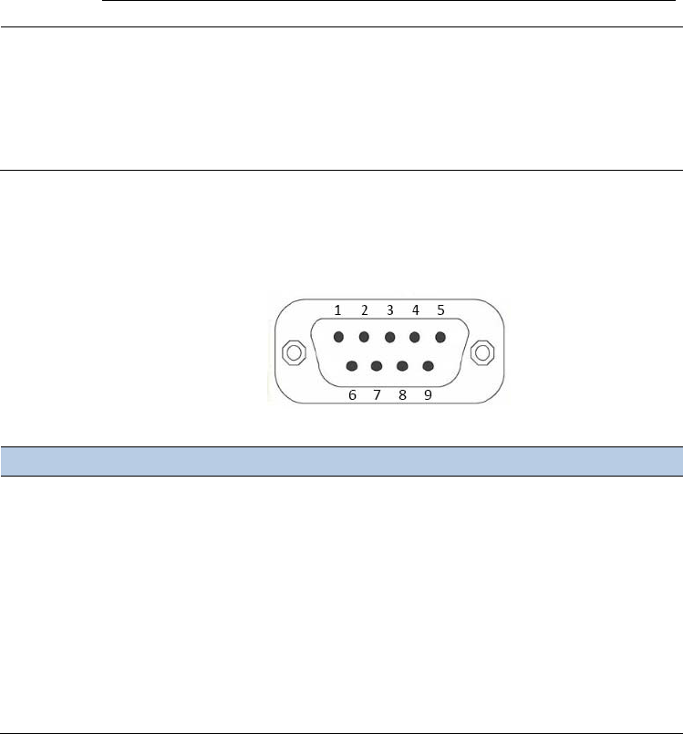
C.I. CHCN72RECEIVERCOM1(10‐PINLEMOPORT)
DEFINITION
PINSignalNameDescription
1RXDRS232‐RX(pass‐throughtothemainboardthroughthispin)
2TXDRS232‐TX(pass‐throughtothemainboardthroughthispin)
3PWRExternalPowerInput(positivepole)
4PWRExternalPowerInput(positivepole)
5PWR,GNDExternalPowerInput(negativepole),ExternalPowerGround
6PWR,GNDExternalPowerInput(negativepole),ExternalPowerGround
7SignalPPSsignaloutput
8NotUsed
9NotUsed
10SignalEVENTsignalinput
C.II. CHCN72RECEIVERCOM2(10‐PINLEMOPORT)
DEFINITION
PINSignalNameDescription
1RXDRS232‐RX(receivedatathroughthispin)
2TXDRS232‐TX(transmitdatathroughthispin)
3PWRExternalPowerInput(positivepole)
4PWRExternalPowerInput(positivepole)
5PWR,GNDExternalPowerInput(negativepole),ExternalPowerGround
C.CommunicationPortsDefinition
N72GNSSReferenceReceiverUserGuidePage62
6PWR,GNDExternalPowerInput(negativepole),ExternalPowerGround
7VBUSUSBdevice
8DMUSBdevice
9DPUSBdevice
10NotUsed
C.III. CHCN72RECEIVERDB9MALECONNECTORDEFINITION
PINSignalNameDescription
1NotUsed
2TXDRS232‐TX(transmitdatathroughthispin)
3RXDRS232‐RX(receivedatathroughthispin)
4NotUsed
5GNDExternalPowerGround
6NotUsed
7NotUsed
8NotUsed
9NotUsed
N72GNSSReferenceReceiverUserGuidePage63
D. GLOSSARY
basestation Alsocalledreferencestation.Abasestationinconstruction,isareceiverplacedat
aknownpointonajobsitethattracksthesamesatellitesasanRTKrover,and
providesareal‐timedifferentialcorrectionmessagestreamthroughradiotothe
rover,toobtaincentimeterlevelpositionsonacontinuousreal‐timebasis.Abase
stationcanalsobeapartofavirtualreferencestationnetwork,oralocationat
whichGPSobservationsarecollectedoveraperiodoftime,forsubsequent
postprocessingtoobtainthemostaccuratepositionforthelocation.
carrierAradiowavehavingatleastonecharacteristic(suchasfrequency,amplitude,or
phase)thatcanbevariedfromaknownreferencevaluebymodulation.
carrierfrequencyThefrequencyoftheunmodulatedfundamentaloutputofaradiotransmitter.The
GPSL1carrierfrequencyis1575.42MHz.
carrierphaseThetimetakenfortheL1orL2carriersignalgeneratedbythesatellitetoreach
theGPSreceiver.Measuringthenumberofcarrierwavesbetweenthesatellite
andreceiverisaveryaccuratemethodofcalculatingthedistancebetweenthem.
CMR
CMR+
CompactMeasurementRecord.Areal‐timemessageformatdevelopedbyTrimble
forbroadcastingcorrectionstootherTrimblemainboardreceivers.CMRisamore
efficientalternativetoRTCM.
DGPSSeereal‐timedifferentialGPS.
differential
correction
DifferentialcorrectionistheprocessofcorrectingGPSdatacollectedonarover
withdatacollectedsimultaneouslyatabasestation.Becausethebasestationis
onaknownlocation,anyerrorsindatacollectedatthebasestationcanbe
measured,andthenecessarycorrectionsappliedtotheroverdata.
Differentialcorrectioncanbedoneinreal‐time,orafterthedatahasbeen
collectedbypostprocessing.
DifferentialGPSSeereal‐timedifferentialGPS.
DOPDilutionofPrecision.AmeasureofthequalityofGPSpositions,basedonthe
geometryofthesatellitesusedtocomputethepositions.Whensatellitesare
widelyspacedrelativetoeachother,theDOPvalueislower,andpositionaccuracy
isgreater.Whensatellitesareclosetogetherinthesky,theDOPishigherandGPS
positionsmaycontainagreaterleveloferror.
PDOP(PositionDOP)indicatesthethree‐dimensionalgeometryofthesatellites.
OtherDOPvaluesincludeHDOP(HorizontalDOP)andVDOP(VerticalDOP),which
indicatetheaccuracyofhorizontalmeasurements(latitudeandlongitude)and
verticalmeasurementsrespectively.PDOPisrelatedtoHDOPandVDOPas
follows:
PDOP²=HDOP²+VDOP²
dual‐frequency
GPS
AtypeofreceiverthatusesbothL1andL2signalsfromGPSsatellites.A
dual‐frequencyreceivercancomputemoreprecisepositionfixesoverlonger
distancesandundermoreadverseconditionsbecauseitcompensatesfor
ionosphericdelays.
EGNOSEuropeanGeostationaryNavigationOverlayService.Asatellite‐based
augmentationsystem(SBAS)thatprovidesafree‐to‐airdifferentialcorrection
serviceforGPS.
EGNOSistheEuropeanequivalentofWAAS,whichisavailableintheUnited

D.Glossary
N72GNSSReferenceReceiverUserGuidePage64
States.
elevationmaskTheanglebelowwhichthereceiverwillnottracksatellites.Normallysetto10
degreestoavoidinterferenceproblemscausedbybuildingsandtrees,and
multipatherrors.
ephemeris/
ephemerides
Alistofpredicted(accurate)positionsorlocationsofsatellitesasafunctionof
time.Asetofnumericalparametersthatcanbeusedtodetermineasatellite’s
position.
Availableasbroadcastephemerisoraspostprocessedpreciseephemeris.
epochThemeasurementintervalofaGPSreceiver.Theepochvariesaccordingtothe
measurementtype:forreal‐timemeasurementitissetatonesecond;for
postprocessedmeasurementitcanbesettoarateofbetweenonesecondand
oneminute.Forexample,ifdataismeasuredevery15seconds,loadingdatausing
30‐secondepochsmeansloadingeveryalternatemeasurement.
firmwareTheprograminsidethereceiverthatcontrolsreceiveroperationsandhardware.
GLONASSGlobalOrbitingNavigationSatelliteSystem.GLONASSisaSovietspace‐based
navigationsystemcomparabletotheAmericanGPSsystem.Theoperational
systemconsistsof21operationaland3non‐operationalsatellitesin3orbit
planes.
GNSSGlobalNavigationSatelliteSystem.
GSOFGeneralSerialOutputFormat.ATrimbleproprietarymessageformat.
HDOPHorizontalDilutionofPrecision.HDOPisaDOPvaluethatindicatestheaccuracy
ofhorizontalmeasurements.OtherDOPvaluesincludeVDOP(verticalDOP)and
PDOP(PositionDOP).
UsingamaximumHDOPisidealforsituationswhereverticalprecisionisnot
particularlyimportant,andyourpositionyieldwouldbedecreasedbythevertical
componentofthePDOP(forexample,ifyouarecollectingdataundercanopy).
L1TheprimaryL‐bandcarrierusedbyGPSsatellitestotransmitsatellitedata.
L2ThesecondaryL‐bandcarrierusedbyGPSsatellitestotransmitsatellitedata.
L5ThethirdL‐bandcarrierusedbyGPSsatellitestotransmitsatellitedata.L5will
provideahigherpowerlevelthantheothercarriers.Asaresult,acquiringand
trackingweaksignalswillbeeasier.
MSASMTSATSatellite‐BasedAugmentationSystem.Asatellite‐basedaugmentation
system(SBAS)thatprovidesafree‐to‐airdifferentialcorrectionserviceforGPS.
MSASistheJapaneseequivalentofWAAS,whichisavailableintheUnitedStates.
multi‐frequency
GPS
Atypeofreceiverthatusesmultiplecarrierphasemeasurements(L1,L2,andL5)
fromdifferentsatellitefrequencies.
multipathInterference,similartoghostsonatelevisionscreenthatoccurswhenGPSsignals
arriveatanantennahavingtraverseddifferentpaths.Thesignaltraversingthe
longerpathyieldsalargerpseudorangeestimateandincreasestheerror.Multiple
pathscanarisefromreflectionsoffthegroundoroffstructuresneartheantenna.
NMEANationalMarineElectronicsAssociation.NMEA0183definesthestandardfor
interfacingmarineelectronicnavigationaldevices.Thisstandarddefinesanumber
of'strings'referredtoasNMEAstringsthatcontainnavigationaldetailssuchas
positions.MostCHCGPSreceiverscanoutputpositionsasNMEAstrings.
PDOPPositionDilutionofPrecision.PDOPisaDOPvaluethatindicatestheaccuracyof

D.Glossary
N72GNSSReferenceReceiverUserGuidePage65
three‐dimensionalmeasurements.OtherDOPvaluesincludeVDOP(verticalDOP)
andHDOP(HorizontalDilutionofPrecision).
UsingamaximumPDOPvalueisidealforsituationswherebothverticaland
horizontalprecisionareimportant.
postprocessingPostprocessingistheprocessingofsatellitedataafterithasbeencollected,in
ordertoeliminateerror.Thisinvolvesusingcomputersoftwaretocomparedata
fromtheroverwithdatacollectedatthebasestation.
real‐time
differential
GPS
Alsoknownasreal‐timedifferentialcorrectionorDGPS.Real‐timedifferentialGPS
istheprocessofcorrectingGPSdataasyoucollectit.Correctionsarecalculatedat
abasestationandthensenttothereceiverthrougharadiolink.Astherover
receivesthepositionitappliesthecorrectionstogiveyouaveryaccurateposition
inthefield.
Mostreal‐timedifferentialcorrectionmethodsapplycorrectionstocodephase
positions.RTKusescarrierphasemeasurements.
WhileDGPSisagenericterm,itscommoninterpretationisthatitentailstheuse
ofsingle‐frequencycodephasedatasentfromaGPSbasestationtoaroverGPS
receivertoprovidesub‐meterpositionaccuracy.Theroverreceivercanbeata
longrange(greaterthan100km(62miles))fromthebasestation.
referencestationSeebasestation
roverAroverisanymobileGPSreceiverthatisusedtocollectorupdatedatainthe
field,typicallyatanunknownlocation.
RTCMRadioTechnicalCommissionforMaritimeServices.Acommissionestablishedto
defineadifferentialdatalinkforthereal‐timedifferentialcorrectionofrovingGPS
receivers.TherearethreeversionsofRTCMcorrectionmessages.AllCHCGPS
receiversuseVersion2protocolforsingle‐frequencyDGPStypecorrections.
CarrierphasecorrectionsareavailableonVersion2,oronthenewerVersion3
RTCMprotocol,whichisavailableoncertainCHCdual‐frequencyreceivers.The
Version3RTCMprotocolismorecompactbutisnotaswidelysupportedas
Version2.
RTKReal‐timekinematic.Areal‐timedifferentialGPSmethodthatusescarrierphase
measurementsforgreateraccuracy.
SBASSatellite‐BasedAugmentationSystem.SBASisbasedondifferentialGPS,but
appliestowidearea(WAAS/EGNOSandMSAS)networksofreferencestations.
Correctionsandadditionalinformationarebroadcastviageostationarysatellites.
signal‐to‐noise
ratio
SNR.Thesignalstrengthofasatelliteisameasureoftheinformationcontentof
thesignal,relativetothesignal’snoise.ThetypicalSNRofasatelliteat30°
elevationisbetween47and50dBHz.ThequalityofaGPSpositionisdegradedif
theSNRofoneormoresatellitesintheconstellationfallsbelow39.
skyplotThesatelliteskyplotconfirmsreceptionofadifferentiallycorrectedGPSsignaland
displaysthenumberofsatellitestrackedbytheGPSreceiver,aswellastheir
relativepositions.
SNRSeesignal‐to‐noiseratio
UTCUniversalTimeCoordinated.Atimestandardbasedonlocalsolarmeantimeat
theGreenwichmeridian.
VRSVirtualReferenceStation.AVRSsystemconsistsofGNSShardware,software,and

D.Glossary
N72GNSSReferenceReceiverUserGuidePage66
communicationlinks.Itusesdatafromanetworkofreferencestationstoprovide
correctionstoeachroverthataremoreaccuratethancorrectionsfromasingle
basestation.
TostartusingVRScorrections,theroversendsitspositiontotheVRSserver.The
VRSserverusesthereferencestationdatatomodelsystematicerrors(suchas
ionosphericnoise)attheroverposition.ItthensendsRTCMorCMRcorrection
messagesbacktotherover.
WAASWideAreaAugmentationSystem.WAASwasestablishedbytheFederalAviation
Administration(FAA)forflightandapproachnavigationforcivilaviation.WAAS
improvestheaccuracyandavailabilityofthebasicGPSsignalsoveritscoverage
area,whichincludesthecontinentalUnitedStatesandoutlyingpartsofCanada
andMexico.
TheWAASsystemprovidescorrectiondataforvisiblesatellites.Correctionsare
computedfromgroundstationobservationsandthenuploadedtotwo
geostationarysatellites.ThisdataisthenbroadcastontheL1frequency,andis
trackedusingachannelontheGPSreceiver,exactlylikeaGPSsatellite.
UseWAASwhenothercorrectionsourcesareunavailable,toobtaingreater
accuracythanautonomouspositions.FormoreinformationonWAAS,refertothe
FAAwebsiteathttp://gps.faa.gov.
TheEGNOSserviceistheEuropeanequivalentandMSASistheJapanese
equivalentofWAAS.

CHC‐ShanghaiHuaCeNavigationTechnolo gyLtd.
BuildingC,NO.599GaojingRoad,
QingpuDistrict,201702Shanghai,China
Tel: +862154260273
Fax:+862164950963
Email:sales@chcnav.com|support@chcnav.com
Website:www.chcnav.com