Huace Navigation Technology A02008 GIS Receiver User Manual
Shanghai Huace Navigation Technology LTD. GIS Receiver
UserManual.wiki
>
Huace Navigation Technology
>
A02008 User Manual
User manual
Navigation menu
Upload a User Manual
Namespaces
Wiki Guide
HTML
PDF
Info
Views
User Manual
Discussion / Help
Navigation

![6. Configuring the Receiver: Other Than Keypad and Display Page 33 X360 GIS Reference Receiver User Guide To open or close all the storage threads, click the [ON] or [OFF] button to the right of Log Status field. NOTE – The [ON] and [OFF] button to the right of Log Status field are the Master Log Switch. Every storage thread can log data only when the Master Log Switch is ON. And users can edit the settings of storage threads only when the Master Log Switch is OFF. To edit the settings of each storage thread, click the [Modify] button to the right of the required storage thread, and then the Recording Edit screen appears:](https://usermanual.wiki/Huace-Navigation-Technology/A02008/User-Guide-3384267-Page-35.png)
![6. Configuring the Receiver: Other Than Keypad and Display Page 34 X360 GIS Reference Receiver User Guide In this screen, you can set all data logging parameters, and determine whether the recording files will be affected by the FTP Push. The parameters are mainly as follows: • On or Off: Select “Yes” or “No” to determine whether to log data when the Master Log Switch is ON. • Recording Name: The name of this storage thread. • Sample Interval: Select the observable rate from the dropdown list. • Store Location: Determine whether to store at internal storage or external storage. • Start Time: Set the start time of data log in UTC. Select “Yes” or “No” option below to determine whether to start logging from the set time. • Duration Time: Set the time interval of recording. • Storage: Set the storage limit of this thread. • Recycle Storage: Select “Yes” or “No” to determine whether to auto delete old files if the storage space is full. • Storage Format: The default format of recording files is HCN. • FTP Push: Decide whether to push the stored files to the FTP server of your choice. Click to save the settings and back to the Log Settings screen. Also, users can click to abandon the changed settings and back to Log Settings screen. NOTE – to delete the record data, you can remove all the eight record data by the total button clear all accounts. Also you can delete each record data by clear button under the selected thread. To delete the recorded files of ANY storage thread, click the [Clear] button to the right of the required storage thread. To delete the recorded files of ALL storage threads, click [Clear All Accounts] button. • FTP Push Settings Use this screen to configure the Receiver to push stored files to the FTP server of your choice. Only files that are configured to use FTP push are transmitted. Click [Modify] button to the right of the required FTP server and the FTP Push Settings screen appears:](https://usermanual.wiki/Huace-Navigation-Technology/A02008/User-Guide-3384267-Page-36.png)
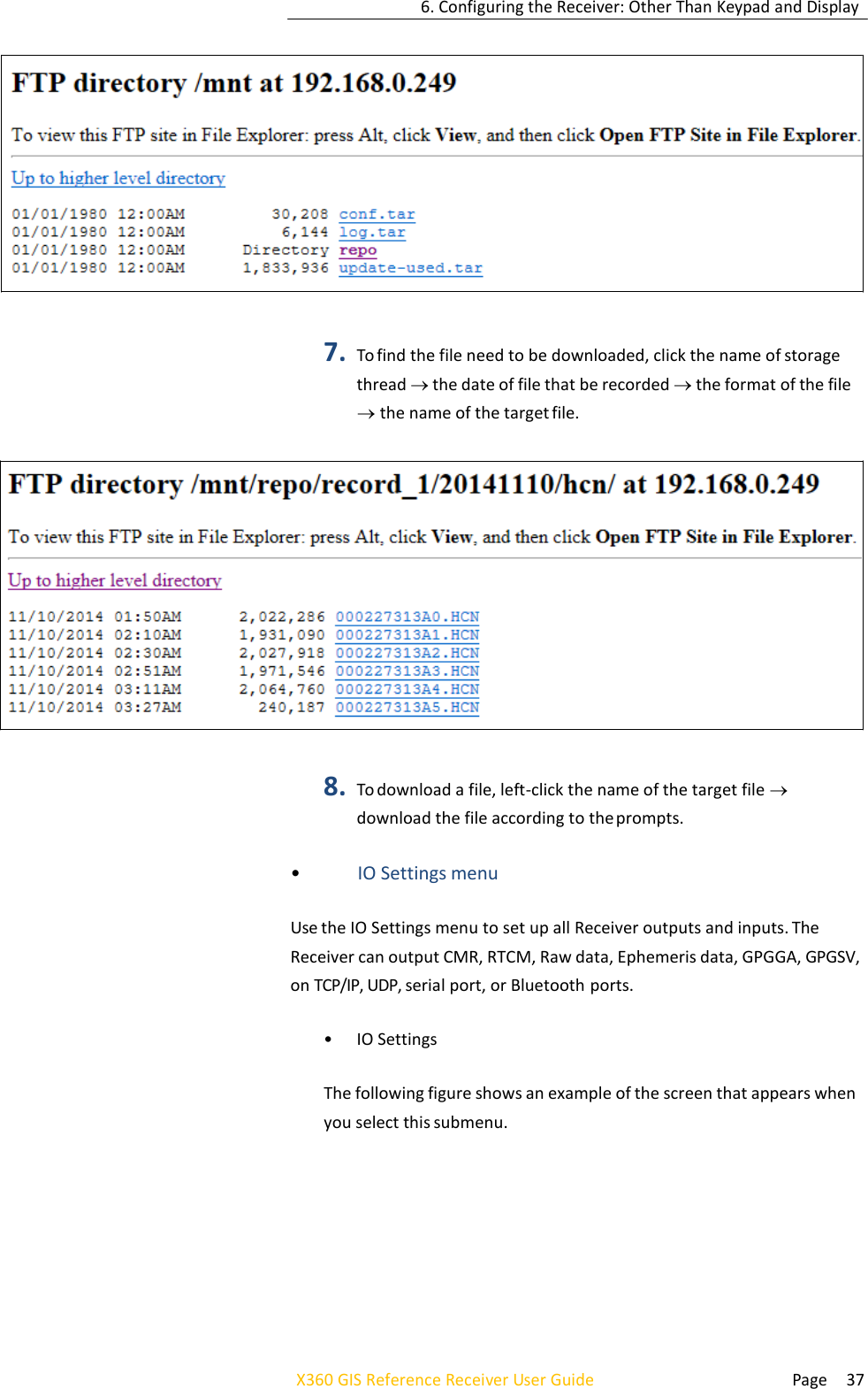
![6. Configuring the Receiver: Other Than Keypad and Display Page 35 X360 GIS Reference Receiver User Guide • FTP Push Recording Shows the related information about the recorded filed that be pushed. And users can click [Clear Ftp Send Log] button in the upper right corner to clear the status of FTP Push operations. • Data Download In this submenu, users can download the data files that recorded in the internal storage through the internal FTP site. 5. Click this submenu, and then the log on dialogue box will prompt you to enter a user name and password: The default logon account for the internal FTP site is: 5.1. User name: ftp 5.2. Password: ftp 6. Click the directory named as repo to view and download the files](https://usermanual.wiki/Huace-Navigation-Technology/A02008/User-Guide-3384267-Page-37.png)
![6. Configuring the Receiver: Other Than Keypad and Display Page 38 X360 GIS Reference Receiver User Guide In this submenu, users can configure 5 types of input and output settings. 1. RTK Client After configuring the settings of RTK client, users can log on CORS or APIS. Click the [Connect] button to the right the IO Settings screen will appear choose one of the connection protocols among the NTRIP, APIS_BASE and APIS_ROVER configure the related parameters click to log on CORS or APIS. A. Connection Protocol: NTRIP B. Connection Protocol: APIS_BASE](https://usermanual.wiki/Huace-Navigation-Technology/A02008/User-Guide-3384267-Page-40.png)
![6. Configuring the Receiver: Other Than Keypad and Display Page 39 X360 GIS Reference Receiver User Guide 4 Connection Protocol: APIS_ROVER 2. TCP/UDP Client Click the [Connect] button to the right of required TCP/UDP Client the IO Settings screen will appear select the connection protocol from the dropdown list enter the IP and Port of the target server configure messages that you want to output to the target server click to save and complete the connection.](https://usermanual.wiki/Huace-Navigation-Technology/A02008/User-Guide-3384267-Page-41.png)
![6. Configuring the Receiver: Other Than Keypad and Display Page 40 X360 GIS Reference Receiver User Guide NOTE: If the Receiver and server are under the same Local Area Network (LAN), users can use the IP address in LAN of the server with any Port. However, if the Receiver and server are under the two different LAN, users should use the public IP address of the server and configure the port mapping of the server. 3. TCP/IP Server Click the [Connect] button to the right of required TCP/IP Server the IO Settings screen will appear select one of the connection protocols between NTRIP and TCP configure the other related parameters click to save the settings and open the server. 5 Connection Protocol: NTRIP 6 Connection Protocol: TCP](https://usermanual.wiki/Huace-Navigation-Technology/A02008/User-Guide-3384267-Page-42.png)
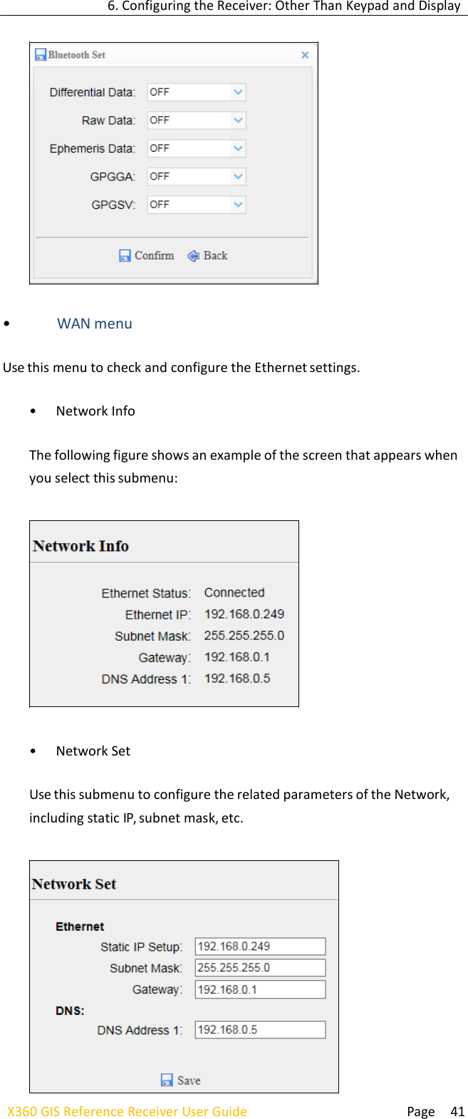
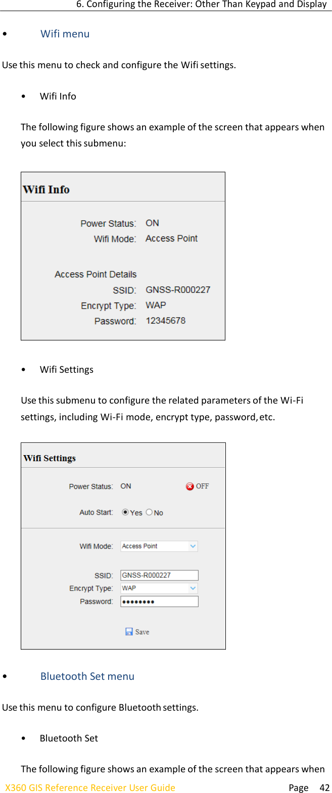
![6. Configuring the Receiver: Other Than Keypad and Display Page 40 X360 GIS Reference Receiver User Guide 4. COM Port Click the [Settings] button to the right of required COM Port the Serial Port Setup screen will appear select Baud Rate used to transmit dataconfigure the messages that you want to output through the serial port click to save the settings and start to transmit. 5. Bluetooth Click the [Settings] button to the right of Bluetooth the Bluetooth Set screen will appear configure the messages that you want to transmit through Bluetooth click to save the settings and start to transmit.](https://usermanual.wiki/Huace-Navigation-Technology/A02008/User-Guide-3384267-Page-43.png)
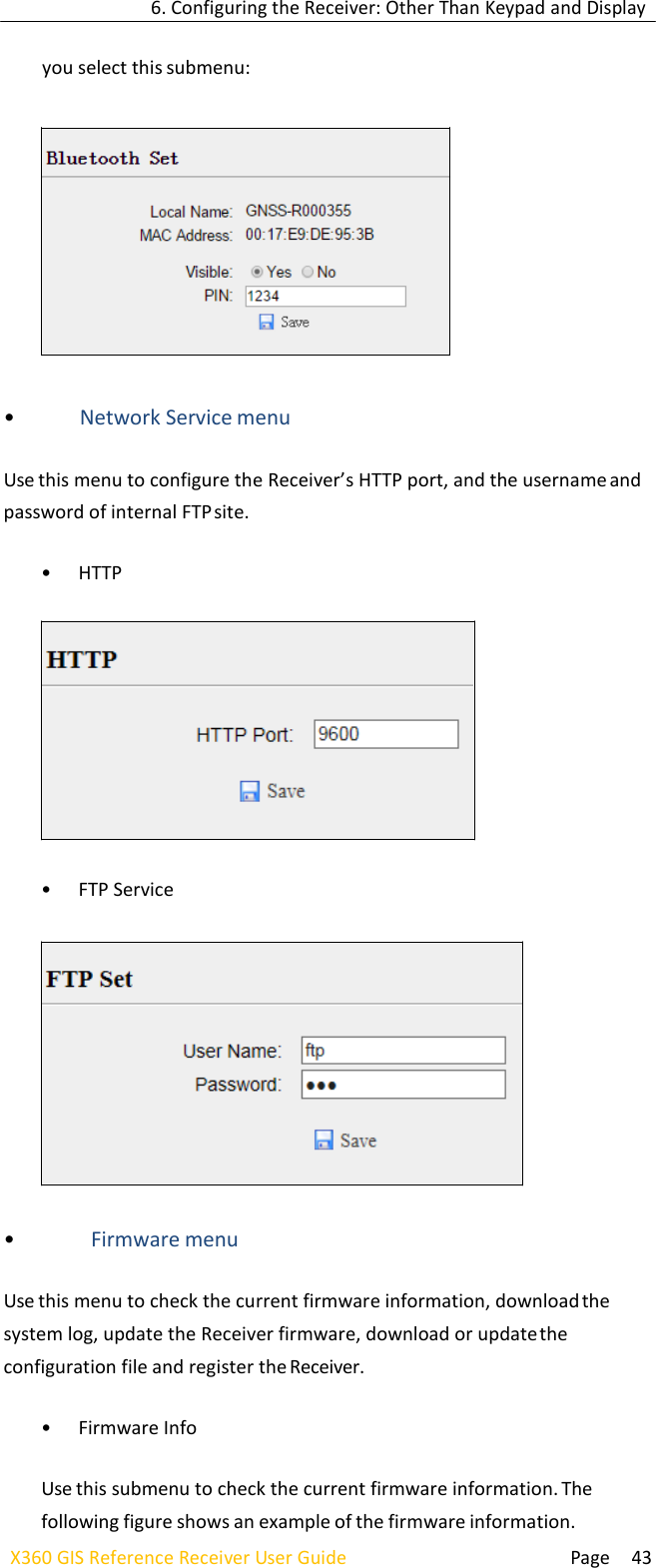
![6. Configuring the Receiver: Other Than Keypad and Display Page 44 X360 GIS Reference Receiver User Guide • System Log Use this submenu to download the system log of the Receiver. • Firmware Update Use this submenu to load new firmware to the Receiver across the network. Click the [Browse] button to locate the upgrade file click [Confirm] button to confirm the selected upgrading file and start upgrading. NOTE: It will take about 2 or 3 minutes to complete the firmware upgrading. • Config File In this submenu, users can download the configuration file by clicking button and determine a saving path to download the configuration file (.cfg file). Also, users can click the [Browse] button to locate the existing configuration file click [Confirm] button to confirm the selected file and start updating.](https://usermanual.wiki/Huace-Navigation-Technology/A02008/User-Guide-3384267-Page-47.png)
![6. Configuring the Receiver: Other Than Keypad and Display Page 45 X360 GIS Reference Receiver User Guide • GNSS Registration Use this submenu to register the Receiver. Paste or enter the registration code to the Registration Code field click [Registration] button to complete the registration.](https://usermanual.wiki/Huace-Navigation-Technology/A02008/User-Guide-3384267-Page-48.png)
![Page 47 X360 GIS Reference Receiver User Guide 7. Default Settings and Application Files • USING CONFIGURATION FILES TO DUPLICATE RECEIVER SETTINGS The X360 GIS Receiver allows the extensive use of application files in order to retain a unique Receiver configuration. With this Receiver, you can create a configuration file that includes most of the Receiver's unique configuration settings. You can then update that configuration file onto one or more other X360 GIS Receivers to quickly configure them to match the Receiver which creates that configuration file. NOTE: The configuration file includes most of the configuration settings except IP Address, IP Mask, Gateway and DNS Server. This is called Receiver configuration cloning or cloning. Receiver cloning greatly reduces the time required to prepare a large group of Receivers for field operations. Log in the web page of the Receiver tap and unfold the Firmware menu tap the Config File submenu click the [Browse] button to locate the existing configuration file click [Confirm] button to confirm the selected file and start updating.](https://usermanual.wiki/Huace-Navigation-Technology/A02008/User-Guide-3384267-Page-50.png)