Huace Navigation Technology A02008 GIS Receiver User Manual
Shanghai Huace Navigation Technology LTD. GIS Receiver
User manual

Safety
Information
il
CHC X360
GIS
Receiver
Revision 1.0
January 2015

Copyright
Copyright 2009-2015 CHC | Shanghai Huace
Navigation Technology LTD. All rights reserved.
The
CHC are trademark of Shanghai Huace
Navigation Technology LTD. All other trademarks
are the
property of their respective owners.
Trademarks
All product and brand names mentioned in this
publication are trademarks of their respective
holders.
Safety Warnings
The Global Positioning System (GPS) is operated by
the U.S. Government, which is solely responsible
for the accuracy and maintenance of the GPS
network. Accuracy can also be affected by poor
satellite geometry and obstructions, like buildings
and heavy canopy.
FCC interference statement
This equipment has been designed to comply with
the limits for a Class B digital device, pursuant to
part 15 of the FCC Rules in the Portable Mode.
These limits are designed to provide reasonable
protection against harmful interference in a
residential installation.
Operation is subject to the following two
conditions: (1) this device may not cause harmful
interference and (2) this device must accept any
interference received, including interference that
may cause undesired operation.
X360 GIS Receiver User Guide – Revision 1.0 January
2015
X360 GIS Reference Receiver User Guide
Page 1

Page
2
X360 GIS Reference
Receiver
User
Guide
SAFETY INFORMATION
Before you use your CHC X360 GIS Receiver, make sure that you have
read
and understood all safety requirements.
REGULATIONS AND SAFETY
The Receiver contains an internal wireless modem for communicating signals
through Bluetooth® wireless technology or through an external data
communications radio. Regulations regarding the use of the wireless modem
vary greatly from country to country. In some countries, the unit can be used
without obtaining an end-user license. Other countries require end-user
licensing. For licensing information, consult your local CHC dealer.
Before operating a X360 GIS Receiver, determine if authorization or a
license to operate the unit is required in your country. It is the responsibility
of the end-user to obtain an operator's permit or license for the Receiver
for
the location or country of use.
TYPE APPROVAL
Type approval, or acceptance, covers technical parameters of the equipment
related to emissions that can cause interference. Type approval is granted to
the manufacturer of the transmission equipment, independent from the
operation or licensing of the units. Some countries have unique technical
requirements for operation in particular radio modem frequency bands. To
comply with those requirements, CHC may have modified your equipment to
be granted Type approval. Unauthorized modification of the units voids the
Type approval, the warranty, and the operational license of the equipment.
EXPOSURE TO RADIO FREQUENCY RADIATION
Safety. Exposure to RF energy is an important safety consideration. The FCC
has adopted a safety standard for human exposure to radio frequency
electromagnetic energy emitted by FCC regulated equipment. Proper use of
this radio modem results in exposure below government limits. The
following precautions are recommended:
C.
Do not operate the transmitter when someone is 20 cm (7.8 inches) of
the antenna.
D.
Do not operate the transmitter unless all RF connectors are secure and
any open connectors are correctly terminated.

Page
3
X360 GIS Reference
Receiver
User
Guide
E.
Do not operate the equipment near electrical blasting caps or in an

Page
4
X360 GIS Reference
Receiver
User
Guide
Safety
Information
explosive atmosphere.
F.
All equipment must be correctly grounded for safe operation.
G.
All equipment should be serviced only by a qualified technician.
BATTERY SAFETY
WARNING – Do not damage the rechargeable Lithium-ion battery. A
damaged battery can cause an explosion or fire, and can result in personal
injury and/or property damage. To prevent injury or damage:
• Do not use or charge the battery if it appears to be damaged. Signs
of damage include, but are not limited to, discoloration, warping,
and leaking battery fluid.
• Do not expose the battery to fire, high temperature, or direct
sunlight.
• Do not immerse the battery in water.
• Do not use or store the battery inside a vehicle during hot weather.
• Do not drop or puncture the battery.
• Do not open the battery or short-circuit its contacts.
WARNING – Avoid contact with the rechargeable Lithium-ion battery if it
appears to be leaking. Battery fluid is corrosive, and contact with it can result
in personal injury and/or property damage. To prevent injury or damage:
• If the battery leaks, avoid contact with the battery fluid.
• If battery fluid gets into your eyes, immediately rinse your eyes with
clean water and seek medical attention. Do not rub your eyes!
• If battery fluid gets onto your skin or clothing, immediately use
clean water to wash off the battery fluid.
WARNING – Charge and use the rechargeable Lithium-ion battery only in
strict accordance with the instructions. Charging or using the battery in
unauthorized equipment can cause an explosion or fire, and can result in
personal injury and/or equipment damage. To prevent injury or damage:
B.
Do not charge or use the battery if it appears to be damaged or
leaking.
C.
Charge the Lithium-ion battery only in a CHC product that is
specified to charge it.
D.
Discontinue charging a battery that gives off extreme heat or a
burning odor.
E.
Use the battery only in CHC equipment that is specified to use it.
F.
Use the battery only for its intended use and according to the
instructions in the product documentation.

Page
5
X360 GIS Reference
Receiver
User
Guide
Safety
Information
DC POWER SUPPLY SAFETY
WARNING – When DC voltage is applied to this Receiver through COM 1 or
COM 2 (Lemo connectors), the DC voltage must be limited to no more than
36 V DC +0% under both normal and single fault conditions. If the
recommended input voltage is exceeded, the Receiver may present an
electrical hazard.
WET LOCATION SAFETY
WARNING – This Receiver is not intended to be used in a wet location, or a
location that may become wet, when it is powered by the external DC power
supply. Use the Receiver in a wet location only when operating it on its own
internal battery.
WARNING – The external power adapter and its associated power cord and
plug are not intended to be installed outdoors, or in a wet location.
WARNING – Do not power the Receiver through external power when
operating in a wet environment or an environment that may become wet.
The power input connections must be sheltered.

Page
5
X360 GIS Reference
Receiver
User
Guide
CONTENTS
Safety Information ........................................................................................................................................... 2
Regulations and safety ............................................................................................................................ 2
Type approval .......................................................................................................................................... 2
Exposure to radio frequency radiation .................................................................................................... 2
Battery safety .......................................................................................................................................... 3
DC power supply safety ........................................................................................................................... 4
Wet location safety .................................................................................................................................. 4
1.
Introduction ................................................................................................................................................. 7
A.
About the Receiver ........................................................................................................................... 7
B.
Technical support .............................................................................................................................. 7
C.
Disclaimer ......................................................................................................................................... 8
D.
Your comments ................................................................................................................................. 8
2.
Overview ...................................................................................................................................................... 9
A.
Receiver framework ......................................................................................................................... 9
• The network appliance concept .......................................................................................... 10
B.
Receiver services ............................................................................................................................ 10
C.
Receiver features ............................................................................................................................ 11
D.
Use and care ................................................................................................................................... 11
E.
Electronic interface ......................................................................................................................... 11
F.
Keypad and display ......................................................................................................................... 12
G.
Rear connectors .............................................................................................................................. 13
3.
Batteries and Power .................................................................................................................................. 14
A.
External power ............................................................................................................................... 15
B.
Battery safety ................................................................................................................................. 15
C.
Battery performance ...................................................................................................................... 16
D.
Charging the battery ....................................................................................................................... 16
E.
Storing the battery.......................................................................................................................... 17
F.
Removing the battery ..................................................................................................................... 17
4.
Setting Up the Receiver ............................................................................................................................. 18
A.
Guidelines ....................................................................................................................................... 18
• Environmental conditions .................................................................................................... 18
• Sources of electrical interference ........................................................................................ 18
• Uninterruptable power supply ............................................................................................ 18
• Lighting and surge protection .............................................................................................. 19
• Placing the antenna ............................................................................................................. 19
B.
System installation.......................................................................................................................... 20
• Supported antenna .............................................................................................................. 20
• System installation diagram................................................................................................. 20
5.
Configuring the Receiver: Other Than Keypad and Display ....................................................................... 22
A.
Configuring the Ethernet settings................................................................................................... 22
B.
Configuring through a web browser ............................................................................................... 23
• Changing the settings .......................................................................................................... 24

Page
6
X360 GIS Reference
Receiver
User
Guide
• Status menu .............................................................................................................. 24
• Satellites menu ......................................................................................................... 27
• Receiver Settings menu ........................................................................................ 29
• Data Recording menu ............................................................................................... 32
• IO Settings menu....................................................................................................... 36
• WAN menu ................................................................................................................ 41
• Wifi menu ................................................................................................................. 42
• Bluetooth Set menu .................................................................................................. 42
• Network Service menu ............................................................................................. 43
• Firmware menu ...................................................................................................... 43
6.
Default Setting and Configuration Files ..................................................................................................... 46
A.
Default Receiver settings ................................................................................................................ 46
• Resetting the Receiver to factory defaults .......................................................................... 46
• Using configuration files to duplicate Receiver settings ...................................................... 47
7.
Specifications ............................................................................................................................................. 48
A.
GNSS characteristics ....................................................................................................................... 48
B.
Communication .............................................................................................................................. 48
C.
Physical ........................................................................................................................................... 49
D.
Electrical ......................................................................................................................................... 49
E.
General ........................................................................................................................................... 49
F.
Data storage ................................................................................................................................... 49
Upgrading the Receiver Firmware ............................................................................................................. 51
• The WinFlash utility ......................................................................................................................... 51
• Installing the WinFlash utility ................................................................................................ 51
• Upgrading the Receiver firmware .................................................................................................. 51
• Upgrading through USB port ................................................................................................ 51
• Upgrading through a browser ............................................................................................. 52
Troubleshooting ........................................................................................................................................ 53
• Receiver issues ................................................................................................................................ 53
Communication Ports Definition ............................................................................................................... 55
CHC X360 Receiver DB9 Male Connector Definition ............................................................................. 55
Glossary ..................................................................................................................................................... 56

Page
7
X360 GIS Reference
Receiver
User
Guide
A.
INTRODUCTION
The X360 GIS Receiver User Guide describes how to set up and use the
CHC
X360 GIS Receiver.
In this manual, “the Receiver” refers to the X360 GIS Receiver unless
otherwise stated.
Even if you have used other Global Navigation Satellite Systems (GNSS)
products before, CHC recommends that you spend some time reading this
manual to learn about the special features of this product. If you are not
familiar with GNSS, go to www.chcnav.com for an interactive look at CHC
and GNSS.
A.I. ABOUT THE RECEIVER
The X360 GIS Receiver (“the Receiver”) is a multiple-frequency GNSS
Receiver. It can track all GPS (L1/L2/)
You can use the front panel of the Receiver or an office computer to
configure the Receiver, access files, and publish data files to a company
Intranet or to the Internet. The Receiver makes it easy for you to set up
a
powerful, flexible, and reliable station for continuous operation.
The Receiver serves in all common geodetic Receiver roles. It can be the
main component in a Continuously Operating Station (CORS), streaming
data to CHC GNSS Infrastructure software. It can also work well as a
campaign Receiver prior to permanent deployment. The Receiver makes
an
excellent portable RTK base station with its internal battery. It also has
specialized capabilities that make it an excellent Receiver for scientific
applications.
A.II. TECHNICAL SUPPORT
If you have a problem and cannot find the information you need in the
product documentation or CHC website (www.chcnav.com), contact your
local CHC dealer from which you purchased the Receiver(s).
If you need to contact CHC technical support, please contact us by email
(support@chcnav.com) or Skype (chc_support).

Page
8
X360 GIS Reference
Receiver
User
Guide
1. Introduction
A.III. DISCLAIMER
Before using the Receiver, please make sure that you have read and
understood this User Guide, as well as the safety requirements. CHC holds
no responsibility for the wrong operation by users and for the losses
incurred by the wrong understanding about this User Guide. However, CHC
reserves the rights to update and optimize the contents in this guide
regularly. Please contact your local CHC dealer for new information.
A.IV. YOUR COMMENTS
Your feedback about this user guide will help us to improve it in future
revision. Please email your comments to support@chcnav.com.

Page
9
X360 GIS Reference
Receiver
User
Guide
B.
OVERVIEW
This chapter introduces the X360 GIS Receiver (“the Receiver”). This
Receiver makes it easy to set up a powerful and reliable Continuously
Operating Station (CORS) or to collect data from temporary field locations.
The Receiver is ideal for the following infrastructure applications:
As part of a GNSS Infrastructure network in conjunction with CHC
Station Network (CRNet) software.
As part of a permanent station with or without supporting software.
A temporary field base station to broadcast RTK corrections and collect
observations for post processing.
B.I. RECEIVER FRAMEWORK
The Receiver integrates the multi-frequency GNSS technology into a
specialized processing and communications framework. The Receiver
can
operate as a standalone station or it can be integrated into a
scalable
network.
With an Internet Protocol (IP) as the primary communications method, you
can use public domain tools, such as a web browser and FTP client, to
configure the Receiver and access logged data files.
NOTE - All s to the Internet refer to either a Wide Area Network
(WAN) or a Local Area Network (LAN) connection.
The Receiver adopts a secured system that requires a password protected
login for configuration changes and/or file access.
Use the network management features to create a base/rover configuration
with a variety of operating modes. You can then enable those modes as
necessary instead of switching the global state of the Receiver from one
mode to another. For example, you can configure a number of streaming
services with different configurations (such as any combination of data
stream, sample interval) on different TCP or UDP ports. To activate one or
more modes, open the connection to the specific port. This allows multiple
clients to access any given streaming service.
These features and many more, shift the model of a GNSS Receiver toward
the concept of a "network appliance".

3.
Batteries
and
Power
Page
10
X360 GIS Reference
Receiver
User
Guide
B.I.i.
THE NETWORK APPLIANCE CONCEPT
Traditionally, a GNSS Receiver has one operator. That person is the only
user
of the Receiver so they can change settings without affecting other
users.
With the X360 GIS Receiver, an operator can configure a Receiver once,
and then make it available as a network appliance for general use by one or
more users (or clients).
This network appliance concept lets you set up the Receiver to provide one
or more services that one or more users can access through a Local Area
Network (LAN) or a Wide Area Network (WAN), such as the Internet. Once
the Receiver is set up, you need make only minimal changes, if any, to the
Receiver configuration.
When the Receiver is operating as a network appliance, it provides services
to all users attached to the Receiver through the network.
Different streamed services may be configured on different ports, for
example, with differing data rates or data combination. To obtain a service,
the client has only to connect to a specific port. In this way, most users do
not need to control the Receiver. Changing global settings, such as masks,
will
affect all users of all services.
The Receiver provides the following standard configuration and data logging
services:
Use
...
To perform...
HTT
P
All manual and automated configuration operations to
manage the logged data file space.
FTP
Remote manual and/or automated operations to manage
the logged data file upload path.
B.II. RECEIVER SERVICES
The Receiver can provide one or more streaming or query services over
a
RS-232 serial port or a TCP/IP port:
Streaming service
Anyone with authorized access can obtain streamed information, such
as GNSS measurements or RTCM corrections, without having to control
or issue commands to the Receiver. The client simply connects to the
port that is streaming the required information.

3.
Batteries
and
Power
Page
11
X360 GIS Reference
Receiver
User
Guide
B.III. RECEIVER FEATURES
220-channels
• GPS: L1C/A,L1,L2
16 GB internal data logging storage
External USB drive support
Integrated battery, provides up to 10 hour operation
Integrated display and keypad for system configuration without a
controller
Integrated Bluetooth wireless technology for cable-free data
transmission
Permanent/semi-permanent and mobile quick setup base station
capability
Easy-to-use Web-interface menu system for rapid configuration and
status checking
Eight independent data logging sessions with configurable memory
pooling
Circulating data logging method
FTP push to allow uploading of logged data files to remote sites
Multiple languages available through the Web interface
NTRIP (Networked Transport of RTCM via Internet Protocol)
client/server/caster support
B.IV. USE AND CARE
This Receiver can withstand the rough treatment and tough environment
that typically occurs in CORS installation. However, it is a high-precision
electronic instrument and should be treated with reasonable care.
CAUTION – Operating or storing the Receiver outside the specified
temperature range can damage it. For more information, see Chapter 8
Specifications.
B.V. ELECTRONIC INTERFACE
3.
Batteries
and
Power
Page
12
X360 GIS Reference
Receiver
User
Guide
High-power signals from a nearby radio or radar transmitter can overwhelm
the Receiver circuits. This does not harm the instrument, but it can prevent
the Receiver electronics from functioning correctly.
Avoid locating the Receiver or antenna within 400 meters of powerful radar,
television, or other transmitters or GNSS antennas. Low-power transmitters,
such as those in cell phones and two-way radios, normally do not interfere
with Receiver operations.
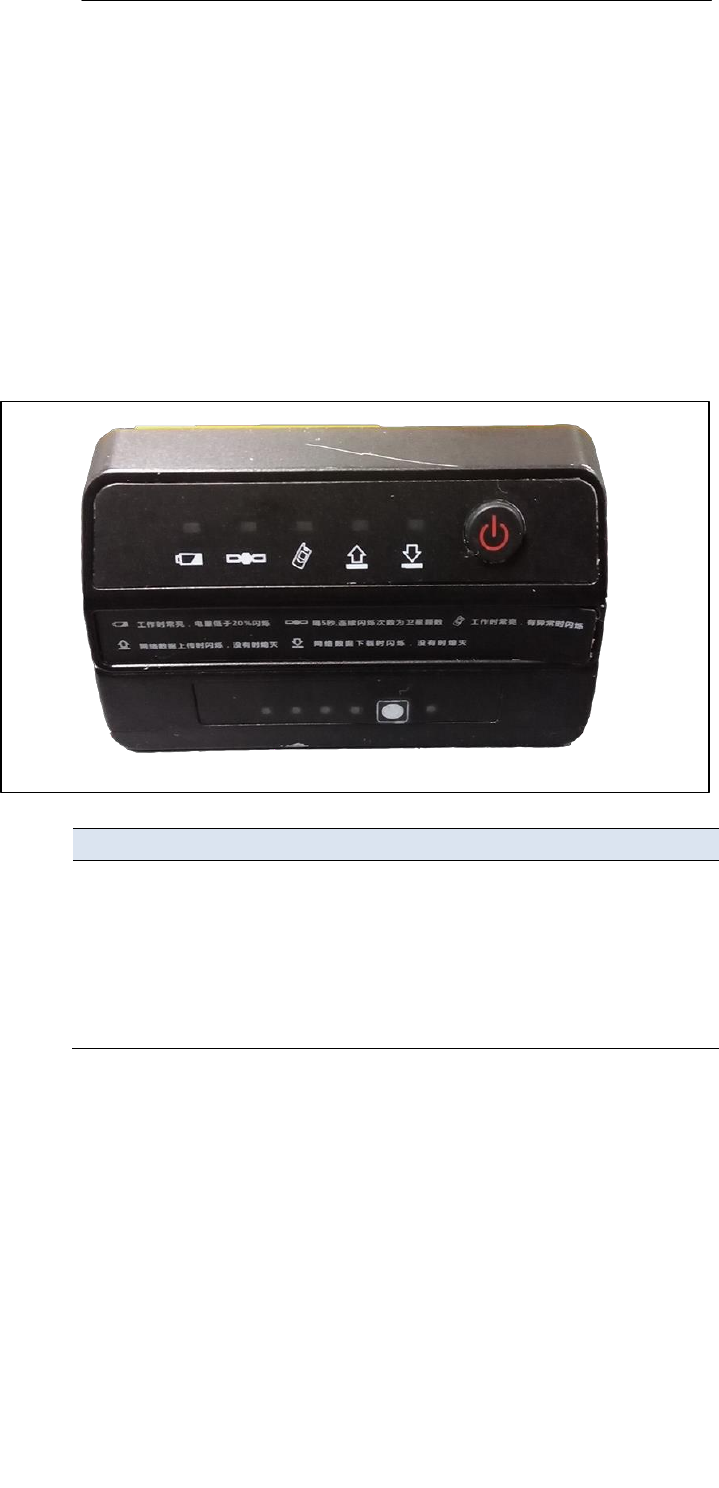
B.VI. KEYPAD AND DISPLAY
Feature Description
1
Power
LED
Shows if the power is on or off.
2
Buttons 1,Battery
LED
2,satellites
4,Upload LED
5,Downloading LED
3.
Batteries
and
Power
Page
13
X360 GIS Reference
Receiver
User
Guide
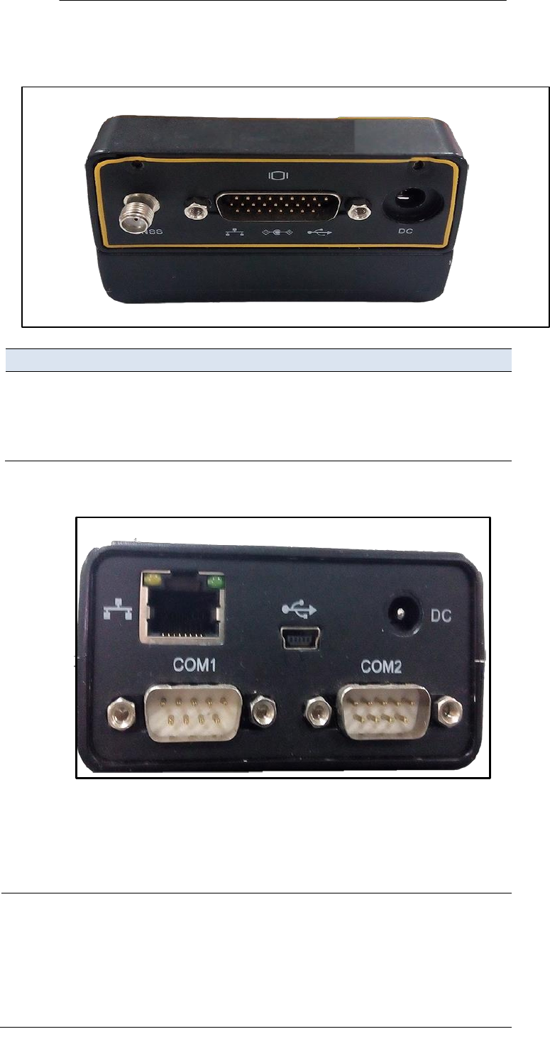
B.VII. REAR CONNECTORS
Connector type
Description
1
TNC
Connect to the GNSS antenna
2
CAN
Can port to connect the external
LAN,DC,USB,COM
port
3
DC
For the power supply
CAN Port Connectors
1
Lemo (10-pin) Port 1
Power from an external AC/DC power supply.
RS-232 serial communications using a 10-
pin
Lemo cable (CHC Data Cable).
Pass-through to the mainboard without
issuing
the pass-through command via this
port.

3.
Batteries
and
Power
Page
14
X360 GIS Reference
Receiver
User
Guide
2
3
4
Lemo (10-pin) Port 2
Rj45 jack
USB
Power from an external AC/DC power supply.
RS-232 serial communications using a 10-
pin
Lemo cable (CHC Data Cable).
Data streaming transmission port.
Supports links to
10BaseT/100BaseT
auto-
negotiate networks
HTTP, TCP/IP, UDP, FTP, NTRIP Caster,
NTRIP
Server, NTRIP Client
Simultaneously transmits multiple
data
stream
Connect to external USB drive for external
data
logging after configured through web
interface.
Upgrade the Receiver firmware with
the
inserted USB driver containing the
related
upgrade file after restart the
Receiver.
Connect the Receiver to a computer to
download files from the Receiver (as
external
storage equipment) to the
computer
.
C.
BATTERIES AND POWER
The X360 GIS Receiver uses an internal rechargeable Lithium-ion
battery,
which can be replaced only at an Authorized CHC Service Center.
The Receiver can also be powered by an external power source that is
connected to either of the Lemo ports.
The operational time provided by the internal battery depends on the type
of measurement and operating conditions. Typically, the internal battery
provides up to 17 hours operation.
NOTE–All battery operational tests are carried out with new,
fully-charged batteries at room temperature, tracking both GPS
satellites while storing and streaming data at 1 Hz. Older
batteries, at
temperatures significantly higher or lower than room
temperature,
will have a reduced performance. Power consumption
increases with
an increasing number of actively tracked satellites and
with increasing
observation and storage rates.

3.
Batteries
and
Power
Page
15
X360 GIS Reference
Receiver
User
Guide
C.I. EXTERNAL POWER
The Receiver uses an external power source in p to its internal battery. If the
Receiver is not connected to an external power source, or if the external
power supply fails, the internal battery is used.
The Receiver’s internal battery charges only when the external voltage is
above 11 V DC. CHC recommends that the applied external power offers
between 12 V DC and 36 V DC and is able to supply at least 4 W of power for
the long-term installations and ensuring that the internal battery is charged
and ready to compensate for power supply disruptions.
While carrying out static measurements for post-processed computations
using the internal memory, if no external power is supplied and the internal
battery is drained, the Receiver shuts down. No data is lost; however, when
power is restored, the Receiver should be configured again.
WARNING – The external AC power adapter and its associated power cord
and plug are not intended to be installed outdoors, nor in a wet location. Do
not power the Receiver through external power when operating in a wet
environment or an environment that may become wet. The power input
connections must be sheltered.
WARNING – When you apply DC voltage to this product through the Lemo
connector, the DC voltage must be limited to 36V DC +0% under both
normal and single fault conditions. This product may present an electrical
hazard if the recommended input voltage is exceeded.
C.II. BATTERY SAFETY
The Receiver is powered by a rechargeable internal Lithium-ion
battery.
Charge and use the battery only in strict accordance with the
following
instructions.
WARNING – Do not damage the rechargeable Lithium-ion battery. A
damaged battery can cause an explosion or fire, and can result in personal
injury and/or property damage.
To prevent injury or damage:
Do not use or charge the battery if it appears to be damaged. Signs of
damage include, but are not limited to, discoloration, warping, and
leaking battery fluid.
Do not expose the battery to fire, high temperature, or direct sunlight.

3.
Batteries
and
Power
Page
16
X360 GIS Reference
Receiver
User
Guide
Do not immerse the battery in water.
Do not use or store the battery inside a vehicle during hot weather.
Do not drop or puncture the battery.
Do not open the battery or short-circuit its contacts.
WARNING – Avoid contact with the rechargeable Lithium-ion battery if it
appears to be leaking. Battery fluid is corrosive, and contact with it can
result in personal injury and/or property damage.
To prevent injury or damage:
If the battery leaks, avoid contact with the battery fluid.
If battery fluid gets into your eyes, immediately rinse your eyes with
clean water and seek medical attention. Do not rub your eyes!
If battery fluid gets onto your skin or clothing, immediately use clean
water to wash off the battery fluid.
C.III. BATTERY PERFORMANCE
To optimize battery performance and extend battery life:
Fully charge all new batteries before use.
C.IV. CHARGING THE BATTERY
The rechargeable Lithium-ion battery is supplied partially charged. Charge
the battery completely before using it for the first time. If the battery has
been stored for longer than three months, charge it before use.
When connected to a suitable power source, the internal battery charges
fully in 10 hours.
WARNING – Charge and use the rechargeable Lithium-ion battery only in
strict accordance with the instructions. Charging or using the battery in
unauthorized equipment can cause an explosion or fire, and can result in
personal injury and/or equipment damage.
To prevent injury or damage:
6.
Do not charge or use the battery if it appears to be damaged or leaking.
7.
Charge the Lithium-ion battery only within the X360 Receiver. The

3.
Batteries
and
Power
Page
17
X360 GIS Reference
Receiver
User
Guide
battery can only be removed by an authorized CHC Service Center.
C.V. STORING THE BATTERY
The internal Lithium-ion battery adopts a self-protection mechanism that
protects the battery from discharge when its voltage is below 6 V and shuts
down the Receiver. The internal battery will be activated when charged by
the external power supply.
The internal battery will only charge from an external power source that
delivers more than 11 V, for example, an AC power adaptor. The Receiver is
supplied with a mains power supply unit that recharges the battery inside
the Receiver when it is connected through the adaptor to either of the Lemo
ports. When you use the Receiver in a long-term installation, CHC
recommends that you use this power supply or another that provides at
least 12 V DC at all times to keep the internal battery charged. This will
ensure that the internal battery provides an uninterrupted power supply
that will keep the Receiver operational for up to 17 hours after a power
failure.
C.VI. REMOVING THE BATTERY
The internal Lithium-ion battery may be removed only at an authorized CHC
Service Center. If the battery is removed at an unauthorized service center,
the remaining warranty on the product will be void.

Page
18
X360 GIS Reference
Receiver
User
Guide
D.
SETTING UP THE RECEIVER
This chapter describes best practices for setting up the equipment, and
outlines the precautions that you must take to protect the equipment. It also
describes the typical installation diagram of station composed of X360
GIS
Receiver, GNSS antenna, external power and network cable.
The antenna installation guidelines described here are the minimum
standards. When installing a geodetic antenna to gather precise observation
data, always follow recommended CORS installation practices to the greatest
extent possible.
D.I. GUIDELINES
When you set up the Receiver, follow these guidelines.
D.I.i.
ENVIRONMENTAL CONDITIONS
The Receiver has a waterproof housing but you must take reasonable care to
keep the unit dry.
To improve the performance and long-term reliability of the Receiver, do not
expose the Receiver to extreme environmental conditions, such as:
Water
Corrosive fluids and gases
D.I.ii.
SOURCES OF ELECTRICAL INTERFERENCE
Do not place the GNSS antenna near the following sources of electrical and
magnetic noise:
Gasoline engines (spark plugs)
Televisions and computer monitors
Alternators and generators
Electric motors
Equipment with DC-to-AC converters
Fluorescent lights
Switching power supplies
Arc welding equipment
D.I.iii.
UNINTERRUPTABLE POWER SUPPLY
CHC recommends that you use an uninterruptible power supply (UPS) to

Page
19
X360 GIS Reference
Receiver
User
Guide
6.
Configuring
the
Receiver:
Other
Than
Keypad
and
Display
power the Receiver. The internal battery can also operate as a UPS for up to
17 hours. A UPS protects the equipment from power surges and spikes, and
keeps the Receiver running during short power outages.
For more information, contact your local CHC dealer.
D.I.iv.
LIGHTING AND SURGE PROTECTION
CHC recommends that you install lightning protection equipment at
permanent sites. All connections to the Receiver should have surge
protection. Typically, the minimum protection should include a surge
protector in the antenna feed line, on the Receiver's power supply system. If
serial devices are attached to the Receiver, those serial connections should
also be provided with surge protection. Also, protect any communications
and power lines at building entry points. If you use other antennas, such as a
radio modem that distributes real-time correction messages, install surge
protection on those antenna feeds as well.
No surge protection devices can offer protection unless they are connected
to an excellent ground using very low impedance conductors. Equipment
damage caused by electrical surges occurs in many permanent installations
even though surge protection is in place. Commonly, this is because the
grounding system used was designed to protect against AC electrical hazards
rather than to dissipate the sudden, high current surges caused by lightning.
Please consult with a lightning protection expert or research the topic when
planning permanent installations.
For more information, contact your local CHC dealer.
D.I.v.
PLACING THE ANTENNA
The antenna location will have a significant effect on the quality of your
X360 Receiver's performance. In temporary developments it may not
always
be possible to set up on an ideal location with an excellent sky view.
However, when installing a permanent station, be sure to plan the antenna
location and mounting system carefully.
The general requirements for the antenna location and mount are:
Keep the distance from the objects that may cause the multipath effects
(such as buildings, trees, reflective surface) for at least 200 m (656 feet)
Clear sky above 10 degrees elevation
Away from electromagnetism interference region (e.g. Microwave
station, radio transmitting station, high voltage wires) at least 200 m
(656 feet)
Mounted 1.5 m (5 feet) above any nearby signal reflectors.

6.
Configuring
the
Receiver:
Other
Than
Keypad
and
Display
�
Page
20
X360 GIS Reference
Receiver
User
Guide
� Mount stability that is not influenced by thermal expansion, wind
loading, or soil expansion/contraction.
For additional information on this topic, research the antenna installation
guidelines published by the:
� US National Geodetic Survey
(http://www.ngs.noaa.gov/PUBS_LIB/CORS_guidelines.pdf)
� International GNSS Service
(http://igscb.jpl.nasa.gov/network/guidelines/guidelines.html)
•
S
YSTEMINSTALLATION
• SUPPORTED ANTENNA
The Receiver provides a TNC-type female connector for connecting to an
antenna. The Receiver is intended for use with a CHC Geodetic GNSS antenna
or a CHC GNSS Choke Ring antenna.
CHC Helical GNSS
Antenna
Other GNSS antennas may however be used ensuring that the antenna
receive the proper GNSS frequencies and operates at either 3.3V or 7.1V
with a signal greater than 40 dB at the antenna port.
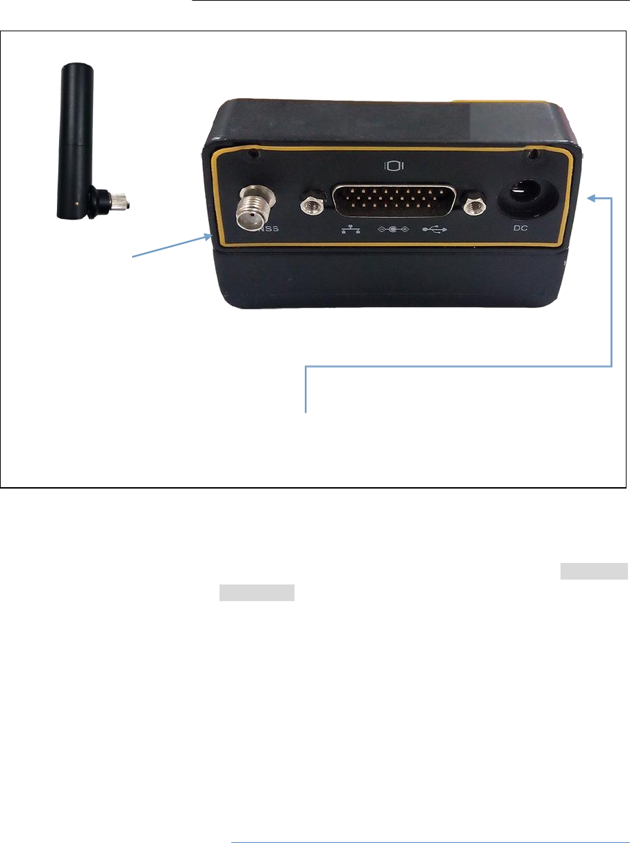
• SYSTEM INSTALLATION DIAGRAM
The typical installation diagram of the CHC X360 GIS Receiver connected
with CHC A220GR GNSS Geodetic Antenna, external power supply and
network cable.
6.
Configuring
the
Receiver:
Other
Than
Keypad
and
Display
�
Page
21
X360 GIS Reference
Receiver
User
Guide
Install the GNSS antenna at the appropriate location (see 4.1.5. Place
the antenna for the guidelines); connect the antenna to the TNC Plug
Socket of X360 via the GNSS Antenna Cable.
1.
Power the X360 by external power source (e.g. mains supply) with
Adapter via CHC Data Cable.
Connect the 10-pin Lemo of CHC Data Cable to COM 1 or COM 2 of
X360.
Plug the male jack connector of Adapter into the female connector
of CHC Data Cable.
Connect two leg plugs or three leg plugs of Adapter to the mains
supply.
2.
Connect the network cable to the RJ45 jack of X360 to link the X360
with network.
NOTE: Also, the X360 can be powered by external battery via CHC
Data Cable. And the power supply voltage should be controlled
between 12 to 36 V DC.
C
H
C
H
e
lic
al
G
N
SS
A
n
te
nn
a
A
d
a
p
te
r

6.
Configuring
the
Receiver:
Other
Than
Keypad
and
Display
Page
22
X360 GIS Reference
Receiver
User
Guide
1.
CONFIGURING THE RECEIVER: OTHER
THAN
KEYPAD AND DISPLAY
You can configure the X360 , GIS Receiver to perform a wide variety of
functions. This chapter describes the configuration methods other than the
front panel display, and explains when and why each method is used.
The WinFlash utility described in this chapter is used primarily to update the
Receiver firmware.
CONFIGURING THE ETHERNET SETTINGS
The Receiver Ethernet port connects to an Ethernet network, through which
you can access, configure, and monitor the Receiver. No serial cable
connection to the Receiver is necessary.
The Receiver has the following Ethernet settings:
5 IP address
6 IP mask
7 Gateway
8 DNS server
9 HTTP port
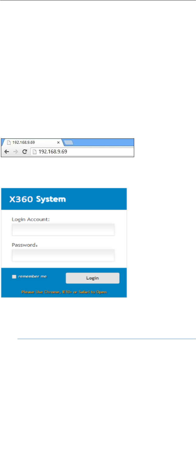
The default setting for the HTTP port is 80: This port is not assigned by the
network. HTTP port 80 is the standard port for web servers and enables you
to connect to the Receiver by entering only the Receiver’s IP address in a
web
browser.
For example, using port 80: http://192.168.9.69
If the Receiver is set to use a port other than 80, you must enter the IP
address followed by the port number in a web browser.
For example, port 9971: http://169.168.9.69:9971
Users can configure the Ethernet settings through the front panel (see 5.4.
Setting up the Receiver as part of an Ethernet configuration) and a web
server. To use a web server, the Receiver must be connected to a network
and have a valid Ethernet configuration.
NOTE: The Receiver should be configured the Ethernet settings
through the front panel for its first connection to the Internet.
6.
Configuring
the
Receiver:
Other
Than
Keypad
and
Display
Page
23
X360 GIS Reference
Receiver
User
Guide
CONFIGURING THROUGH A WEB BROWSER
Supported browsers:
Google Chrome
Microsoft
Internet
Explorer
○
R
version
10,
or
higher
Apple Safari
To connect to the Receiver through a web browser:
1.
Enter the IP address of the Receiver into the address bar of the
web
browser:
2.
The web browser prompts you to enter a username and password:
The default login account for the Receiver is:
Login Account: admin
Password: password
NOTE: Tick remember me option, and then the browser will
remember the Login Account and Password you entered for the next
time you enter this login screen.
3.
Once you are logged in, the web page appears as follows:
6.
Configuring
the
Receiver:
Other
Than
Keypad
and
Display
Page
24
X360 GIS Reference
Receiver
User
Guide
• CHANGING THE SETTINGS
The web interface shows the configuration menus on the left of the browser
window, and the setting on the right. Each configuration menu contains the
related submenus to configure the Receiver and monitor Receiver
performance.
This section describes each configuration menu.
To view the web interface in another language, select the corresponding
language name from the drop-down list in the upper right corner of the
interface.
Currently, three languages are available:
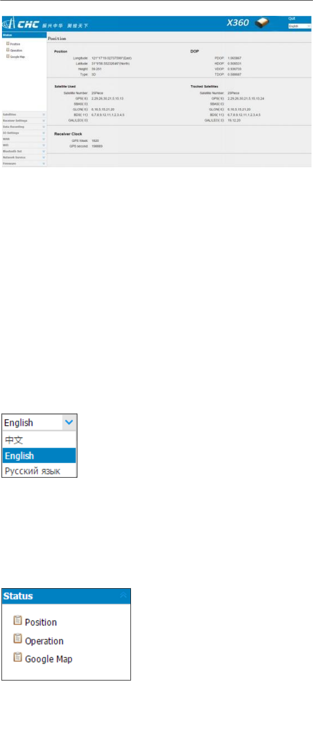
• Status menu
This menu provides a quick link to review the Receiver's position
information,
satellites tracked, runtime, current data log status, current
outputs, available
memory, and more.
• Position

6.
Configuring
the
Receiver:
Other
Than
Keypad
and
Display
Page
25
X360 GIS Reference
Receiver
User
Guide
This page shows the relevant position information about the Receiver's
position solution which including the position, DOP values, satellites
used and tracked, and the Receiver clock information.
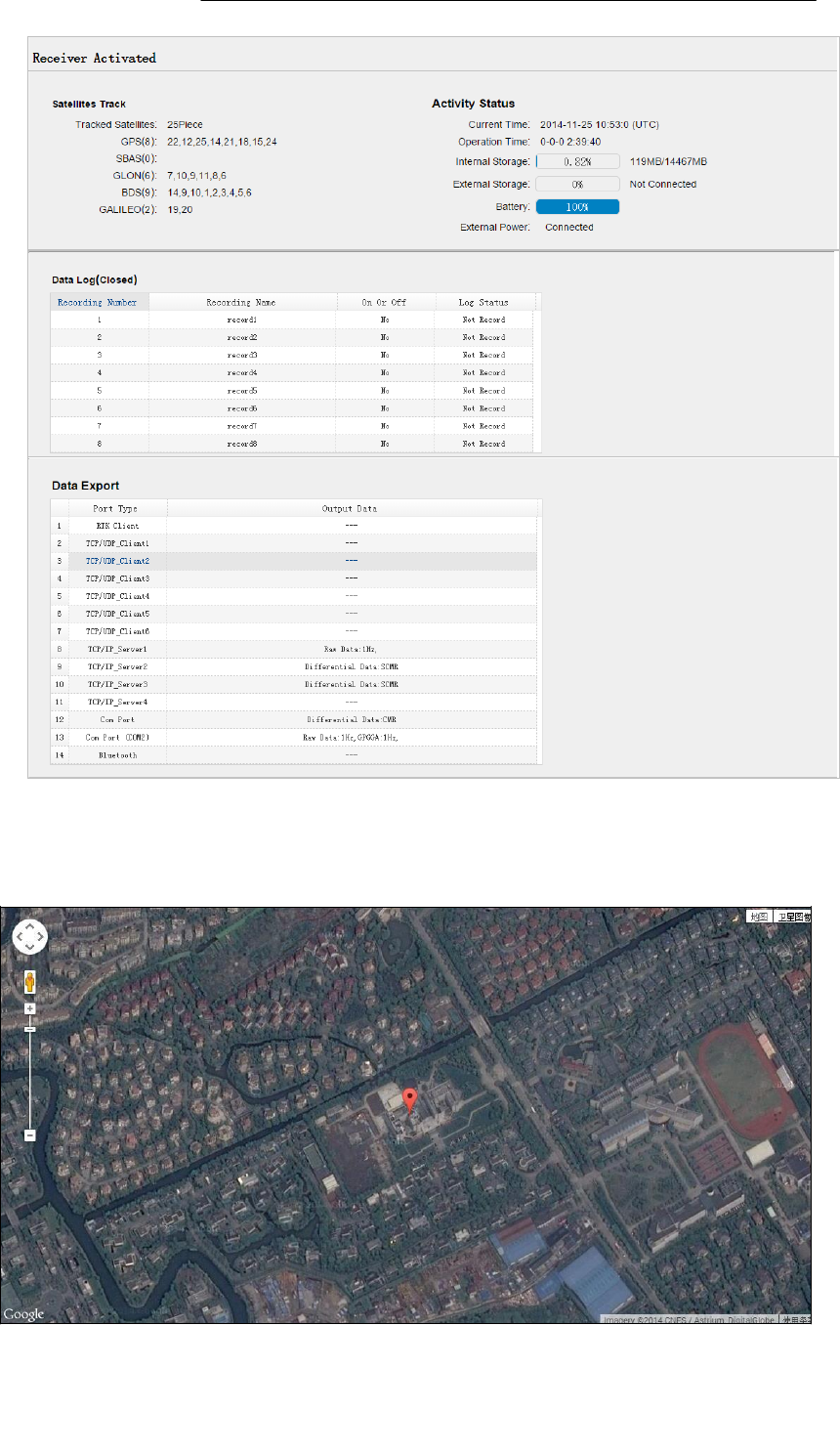
• Operation
Lists several important items to help you understand how the Receiver
is
being used and its current operating condition. Items include the
identities of currently tracked satellites, internal and external storage
usage rate, how long the Receiver has been operational, state of the
internal battery, power source state, files being logged, and data
streams being output. With this information, it is easy to tell exactly
what functions the Receiver is performing:
6.
Configuring
the
Receiver:
Other
Than
Keypad
and
Display
Page
26
X360 GIS Reference
Receiver
User
Guide
• Google map
Tap this submenu to show the location of the Receiver on Google map.
6.
Configuring
the
Receiver:
Other
Than
Keypad
and
Display
Page
27
X360 GIS Reference
Receiver
User
Guide
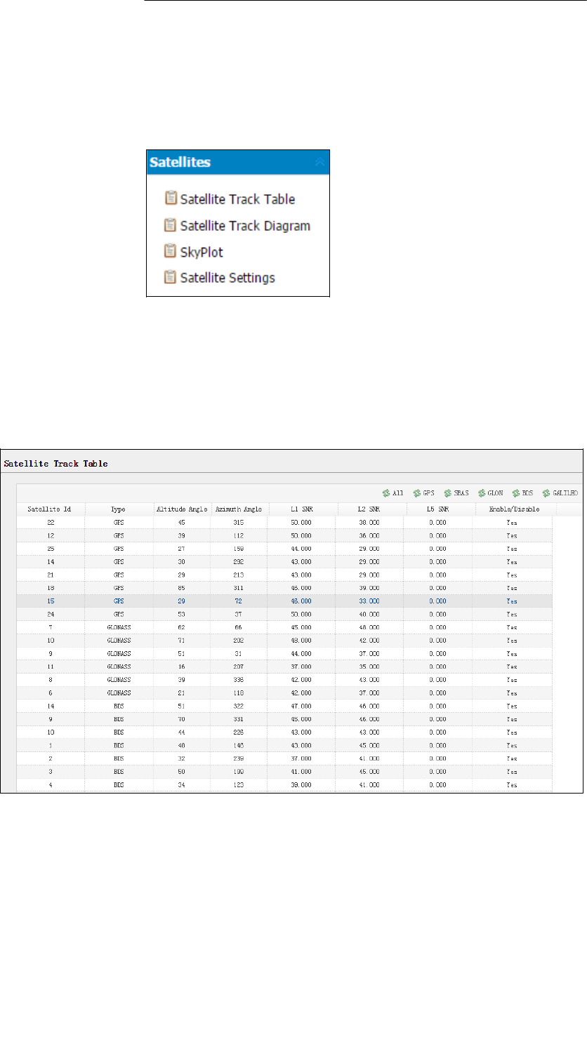
• Satellites menu
Use the Satellites menu to view satellite tracking details and enable/disable
GPS.These menus include
tabular and graphical displays to provide all
required information on satellite
tracking status.
• Satellite Track Table
Provides the status of satellites tracked in general, such as the satellite
ID, satellite type, attitude angle, azimuth angle, L1 SNR, L2 SNR, L5 SNR
and enable/disable status of each one.
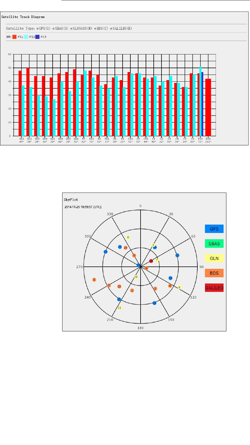
• Satellite Track Diagram
The following figure is an example of satellite track diagram page. Users
can determine the satellite types and the corresponding SNR of L-band
carriers to be displayed in any combination.
6.
Configuring
the
Receiver:
Other
Than
Keypad
and
Display
Page
28
X360 GIS Reference
Receiver
User
Guide
• SkyPlot
The following figure is an example of Skyplot page.
• Satellite Settings
In this submenu, users can enable/disable GPS constellations.
6.
Configuring
the
Receiver:
Other
Than
Keypad
and
Display
Page
29
X360 GIS Reference
Receiver
User
Guide
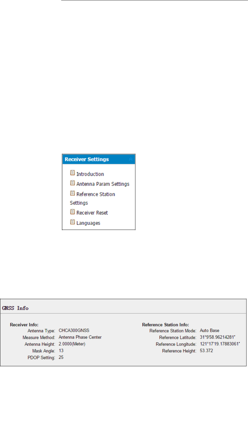
• Receiver Settings menu
Use this menu to configure settings such as the antenna type and height,
elevation mask and PDOP setting, the station coordinates, Receiver
resetting and web interface language:
• Introduction
This submenu shows the Receiver information and station information,
including antenna related information, elevation mask angle, station
work mode and position, etc.
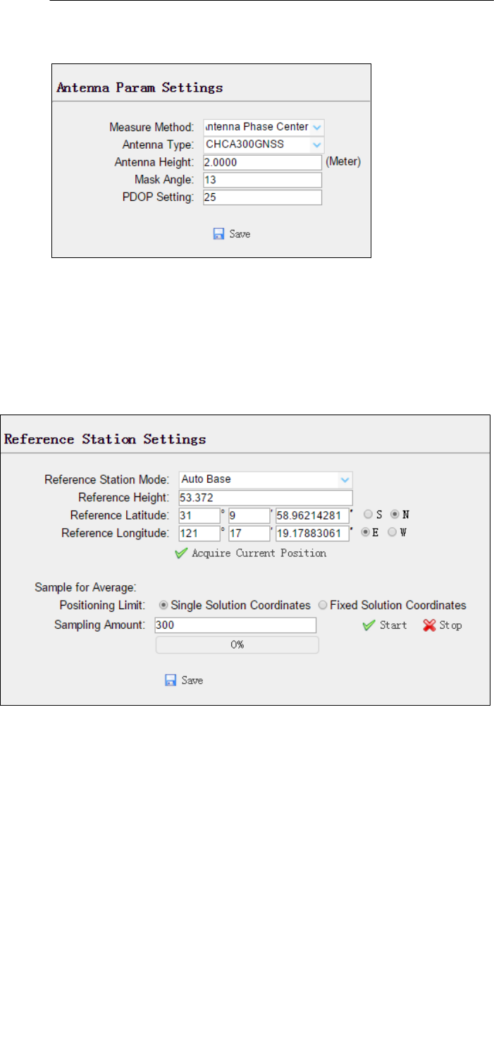
• Antenna Param Settings
Use this screen to configure all of the items relating to the GNSS
antenna. You must enter the correct values for all antenna-related fields,
as the choices you make significantly affect the accuracy for logged data
6.
Configuring
the
Receiver:
Other
Than
Keypad
and
Display
Page
30
X360 GIS Reference
Receiver
User
Guide
and broadcast RTK correctors:
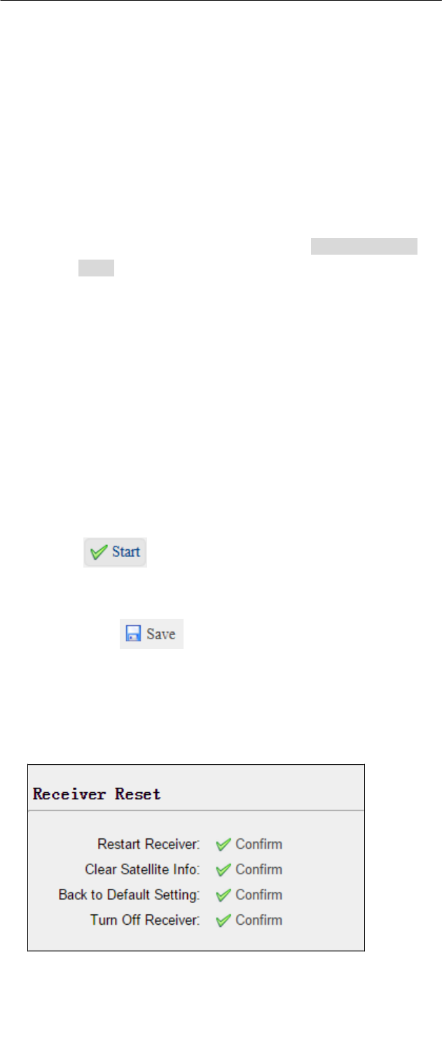
• Station Settings
Use this screen to configure settings such as the station coordinates. You
must enter accurate information in these fields, as this data significantly
affects the accuracy of logged data files and broadcast RTK correctors.
For
Station Mode:
There are three available options: Auto Rover, Auto Base and
Manual Base.
• Auto Rover: The Receiver will serve as Rover after the restart.
• Auto Base: The Receiver will serve as Base after the restart,
and
then broadcast RTK correctors based on coordinates
obtained
through single-point positioning automatically.
• Manual Base: The Receiver will serve as Base after the
restart,
and then broadcast RTK correctors based on the
coordinates
before power off.
6.
Configuring
the
Receiver:
Other
Than
Keypad
and
Display
Page
31
X360 GIS Reference
Receiver
User
Guide
For
Latitude and Longitude:
There are mainly three methods to enter the coordinates and
shown as follows:
• Acquire Current Position: Click this button to acquire current
position obtained through single-point positioning
automatically.
• Manual Input: Manually input a known coordinates.
• From CORS: After logging in CORS, the Receiver will obtain
a
coordinates based on fix solution. (See 6.2.1.5. IO Settings
menu for more details about logging in CORS.)
For Sample for Average:
Users can determine the positioning limit and sampling amount.
The positioning limit falls into two types:
• Single Solution Coordinates: Collect the coordinates of
Receiver
obtained through single-point positioning.
• Fixed Solution Coordinates: Only collect coordinates of
Receiver based on fix solution.
After the configuration of positioning limit and sampling amount,
click to carry out sampling and averaging the result
will be served as the coordinates of current positon.
Also, users can click to save the curent settings.
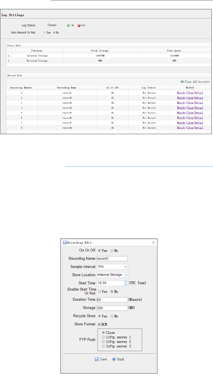
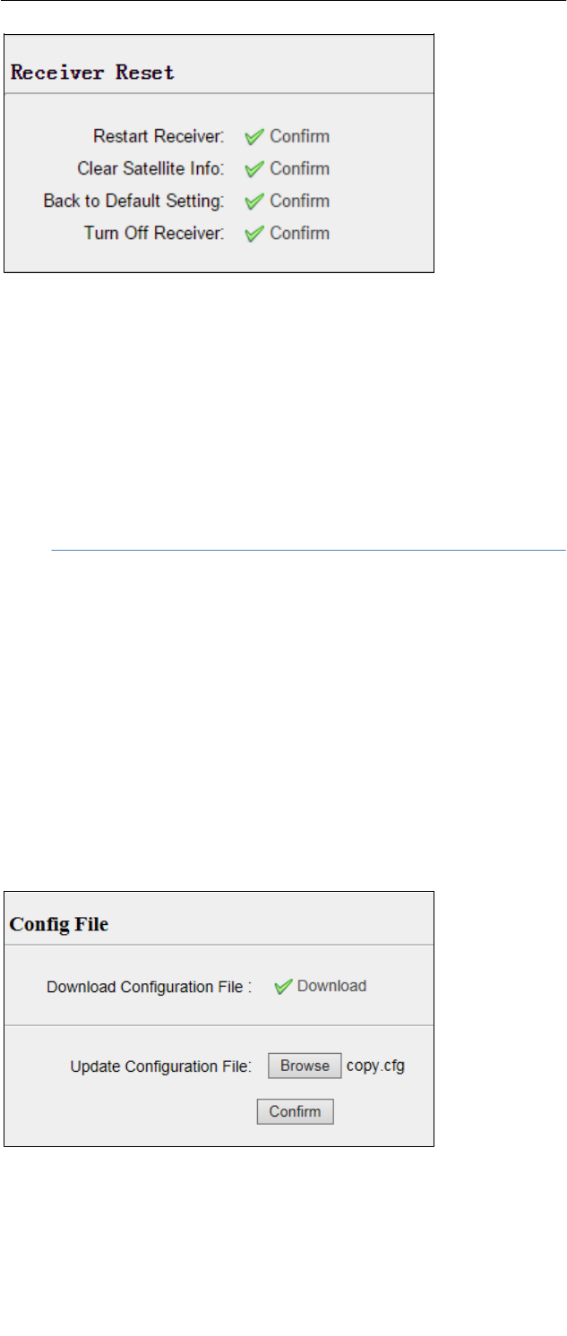
• Receiver Reset
Use this screen to completely or partially reset the Receiver:
• Languages

6.
Configuring
the
Receiver:
Other
Than
Keypad
and
Display
Page
32
X360 GIS Reference
Receiver
User
Guide
Use this screen to select the web interface language:
• Data Recording menu
Use the Data Logging menu to set up the Receiver to log static GNSS data and
to view the logging settings. You can configure settings such as observable
rate, recording rate, continuous logging limit, and whether to auto delete old
files if memory is low. This menu also provides the controls for the FTP push
feature:
• Log Settings
Shows the data logging status, internal and external storage usage and
data logging status of each storage thread. Also, users can configure the
data logging settings for each storage thread, including recording name,
saving location, storage limit, store formats, start time, etc.
6.
Configuring
the
Receiver:
Other
Than
Keypad
and
Display
Page
33
X360 GIS Reference
Receiver
User
Guide
To open or close all the storage threads, click the [ON] or [OFF] button
to the right of Log Status field.
NOTE – The [ON] and [OFF] button to the right of Log Status field are
the Master Log Switch. Every storage thread can log data only when
the Master Log Switch is ON. And users can edit the settings of
storage threads only when the Master Log Switch is OFF.
To edit the settings of each storage thread, click the [Modify] button to
the right of the required storage thread, and then the Recording Edit
screen appears:

6.
Configuring
the
Receiver:
Other
Than
Keypad
and
Display
Page
34
X360 GIS Reference
Receiver
User
Guide
In this screen, you can set all data logging parameters, and
determine whether the recording files will be affected by the FTP
Push. The parameters are mainly as follows:
• On or Off: Select “Yes” or “No” to determine whether to log
data when the Master Log Switch is ON.
• Recording Name: The name of this storage thread.
• Sample Interval: Select the observable rate from the dropdown
list.
• Store Location: Determine whether to store at internal storage
or external storage.
• Start Time: Set the start time of data log in UTC. Select “Yes” or
“No” option below to determine whether to start logging from
the set time.
• Duration Time: Set the time interval of recording.
• Storage: Set the storage limit of this thread.
• Recycle Storage: Select “Yes” or “No” to determine whether to
auto delete old files if the storage space is full.
• Storage Format: The default format of recording files is HCN.
• FTP Push: Decide whether to push the stored files to the FTP
server of your choice.
Click to save the settings and back to the Log Settings
screen. Also, users can click to abandon the changed
settings and back to Log Settings screen.
NOTE – to delete the record data, you can remove all the eight record
data by the total button clear all accounts. Also you can delete each
record data by clear button under the selected thread.
To delete the recorded files of ANY storage thread, click the [Clear]
button to the right of the required storage thread.
To delete the recorded files of ALL storage threads, click [Clear All
Accounts] button.
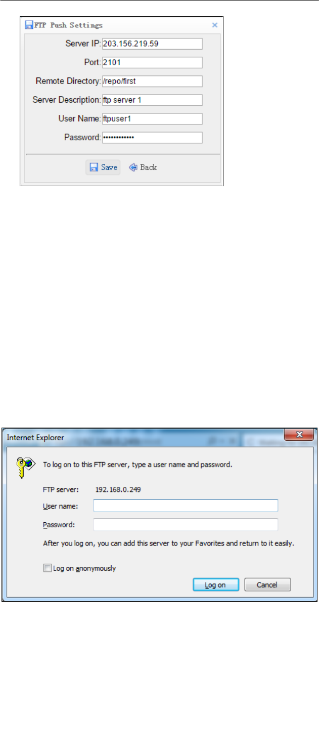
• FTP Push Settings
Use this screen to configure the Receiver to push stored files to the FTP
server of your choice. Only files that are configured to use FTP push are
transmitted. Click [Modify] button to the right of the required FTP
server and the FTP Push Settings screen appears:
6.
Configuring
the
Receiver:
Other
Than
Keypad
and
Display
Page
35
X360 GIS Reference
Receiver
User
Guide
• FTP Push Recording
Shows the related information about the recorded filed that be pushed.
And users can click [Clear Ftp Send Log] button in the upper right corner
to clear the status of FTP Push operations.
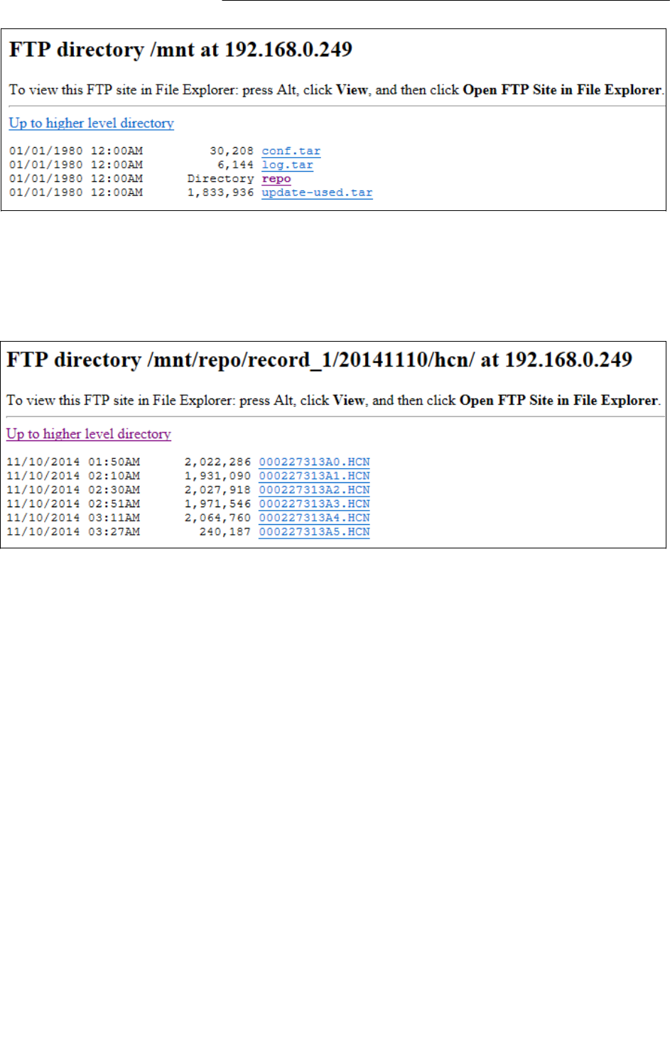
• Data Download
In this submenu, users can download the data files that recorded in the
internal storage through the internal FTP site.
5.
Click this submenu, and then the log on dialogue box will prompt
you to enter a user name and password:
The default logon account for the internal FTP site is:
5.1. User name: ftp
5.2. Password: ftp
6.
Click the directory named as repo to view and download the files

6.
Configuring
the
Receiver:
Other
Than
Keypad
and
Display
Page
36
X360 GIS Reference
Receiver
User
Guide
currently stored on the Receiver:
6.
Configuring
the
Receiver:
Other
Than
Keypad
and
Display
Page
37
X360 GIS Reference
Receiver
User
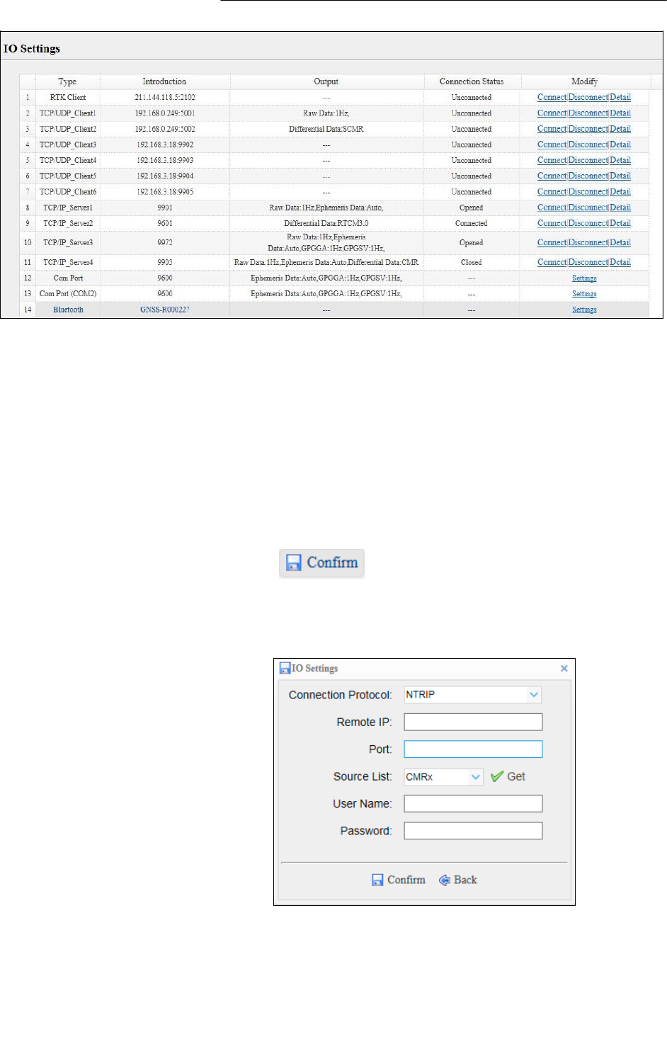
Guide
7.
To find the file need to be downloaded, click the name of storage
thread the date of file that be recorded the format of the file
the name of the target file.
8.
To download a file, left-click the name of the target file
download the file according to the prompts.
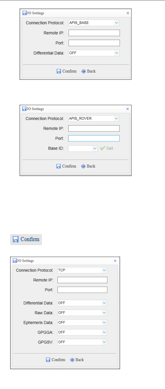
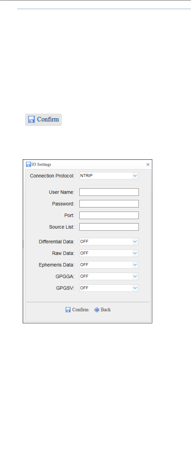
• IO Settings menu
Use the IO Settings menu to set up all Receiver outputs and inputs. The
Receiver can output CMR, RTCM, Raw data, Ephemeris data, GPGGA, GPGSV,
on TCP/IP, UDP, serial port, or Bluetooth ports.
• IO Settings
The following figure shows an example of the screen that appears when
you select this submenu.
6.
Configuring
the
Receiver:
Other
Than
Keypad
and
Display
Page
38
X360 GIS Reference
Receiver
User
Guide
In this submenu, users can configure 5 types of input and output
settings.
1.
RTK Client
After configuring the settings of RTK client, users can log on CORS or
APIS. Click the [Connect] button to the right the IO Settings screen will
appear choose one of the connection protocols among the NTRIP,
APIS_BASE and APIS_ROVER configure the related parameters
click to log on CORS or APIS.
A.
Connection Protocol: NTRIP
B.
Connection Protocol: APIS_BASE
6.
Configuring
the
Receiver:
Other
Than
Keypad
and
Display
Page
39
X360 GIS Reference
Receiver
User
Guide
4 Connection Protocol: APIS_ROVER
2.
TCP/UDP Client
Click the [Connect] button to the right of required TCP/UDP Client
the IO Settings screen will appear select the connection protocol
from the dropdown list enter the IP and Port of the target server
configure messages that you want to output to the target server click
to save and complete the connection.
6.
Configuring
the
Receiver:
Other
Than
Keypad
and
Display
Page
40
X360 GIS Reference
Receiver
User
Guide
NOTE: If the Receiver and server are under the same Local Area
Network (LAN), users can use the IP address in LAN of the server with
any Port. However, if the Receiver and server are under the two
different LAN, users should use the public IP address of the server
and configure the port mapping of the server.
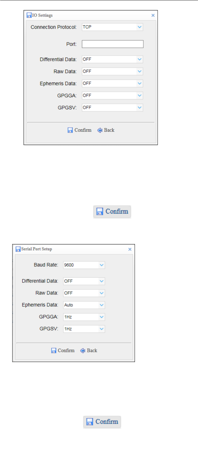
3.
TCP/IP Server
Click the [Connect] button to the right of required TCP/IP Server the
IO Settings screen will appear select one of the connection protocols
between NTRIP and TCP configure the other related parameters
click to save the settings and open the server.
5 Connection Protocol: NTRIP
6 Connection Protocol: TCP
6.
Configuring
the
Receiver:
Other
Than
Keypad
and
Display
Page
40
X360 GIS Reference
Receiver
User
Guide
4.
COM Port
Click the [Settings] button to the right of required COM Port the
Serial Port Setup screen will appear select Baud Rate used to
transmit dataconfigure the messages that you want to output
through the serial port click to save the settings and
start to transmit.
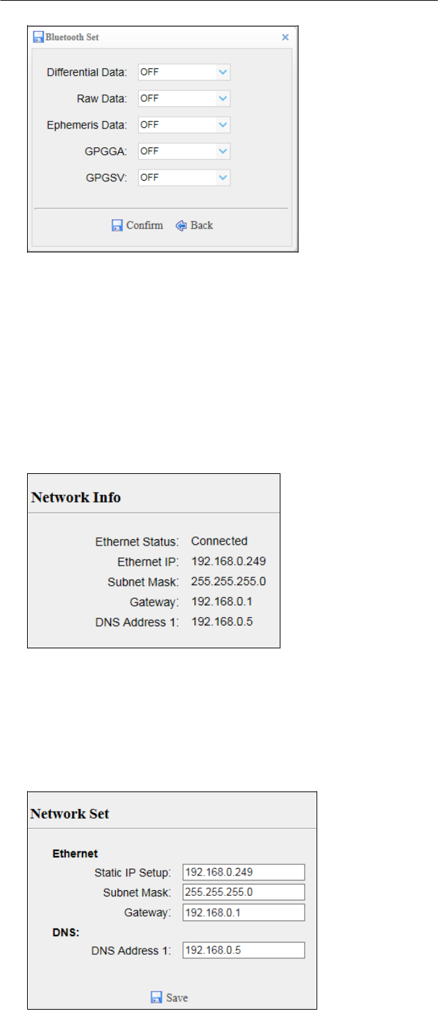
5.
Bluetooth
Click the [Settings] button to the right of Bluetooth the Bluetooth Set
screen will appear configure the messages that you want to transmit
through Bluetooth click to save the settings and start
to transmit.
6.
Configuring
the
Receiver:
Other
Than
Keypad
and
Display
Page
41
X360 GIS Reference
Receiver
User
Guide
• WAN menu
Use this menu to check and configure the Ethernet settings.
• Network Info
The following figure shows an example of the screen that appears when
you select this submenu:
• Network Set
Use this submenu to configure the related parameters of the Network,
including static IP, subnet mask, etc.
6.
Configuring
the
Receiver:
Other
Than
Keypad
and
Display
Page
42
X360 GIS Reference
Receiver
User
Guide
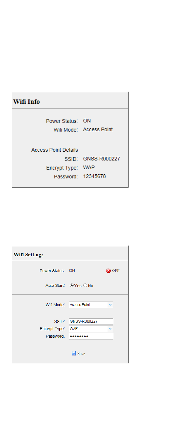
• Wifi menu
Use this menu to check and configure the Wifi settings.
• Wifi Info
The following figure shows an example of the screen that appears when
you select this submenu:
• Wifi Settings
Use this submenu to configure the related parameters of the Wi-Fi
settings, including Wi-Fi mode, encrypt type, password, etc.
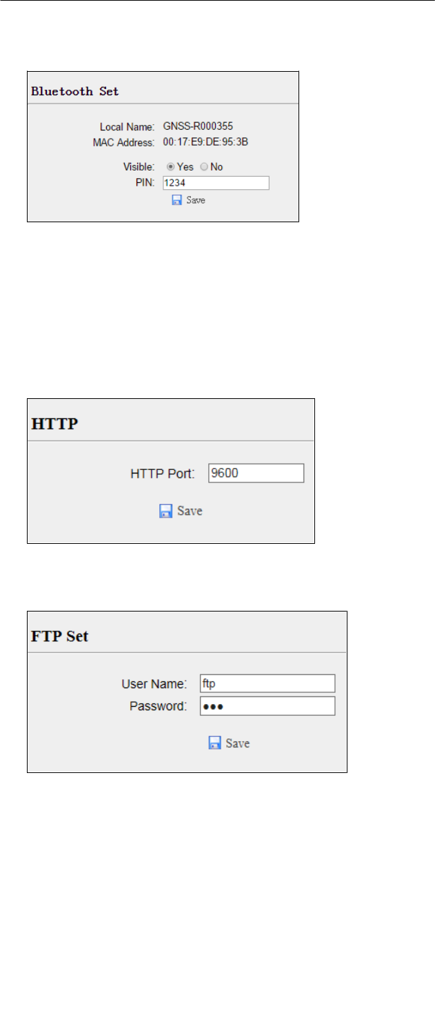
• Bluetooth Set menu
Use this menu to configure Bluetooth settings.
• Bluetooth Set
The following figure shows an example of the screen that appears when
6.
Configuring
the
Receiver:
Other
Than
Keypad
and
Display
Page
43
X360 GIS Reference
Receiver
User
Guide
you select this submenu:
• Network Service menu
Use this menu to configure the Receiver’s HTTP port, and the username and
password of internal FTP site.
• HTTP
• FTP Service
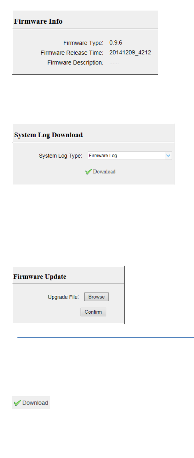
• Firmware menu
Use this menu to check the current firmware information, download the
system log, update the Receiver firmware, download or update the
configuration file and register the Receiver.
• Firmware Info
Use this submenu to check the current firmware information. The
following figure shows an example of the firmware information.
6.
Configuring
the
Receiver:
Other
Than
Keypad
and
Display
Page
44
X360 GIS Reference
Receiver
User
Guide
• System Log
Use this submenu to download the system log of the Receiver.
• Firmware Update
Use this submenu to load new firmware to the Receiver across the
network. Click the [Browse] button to locate the upgrade file click
[Confirm] button to confirm the selected upgrading file and start
upgrading.
NOTE: It will take about 2 or 3 minutes to complete the firmware
upgrading.
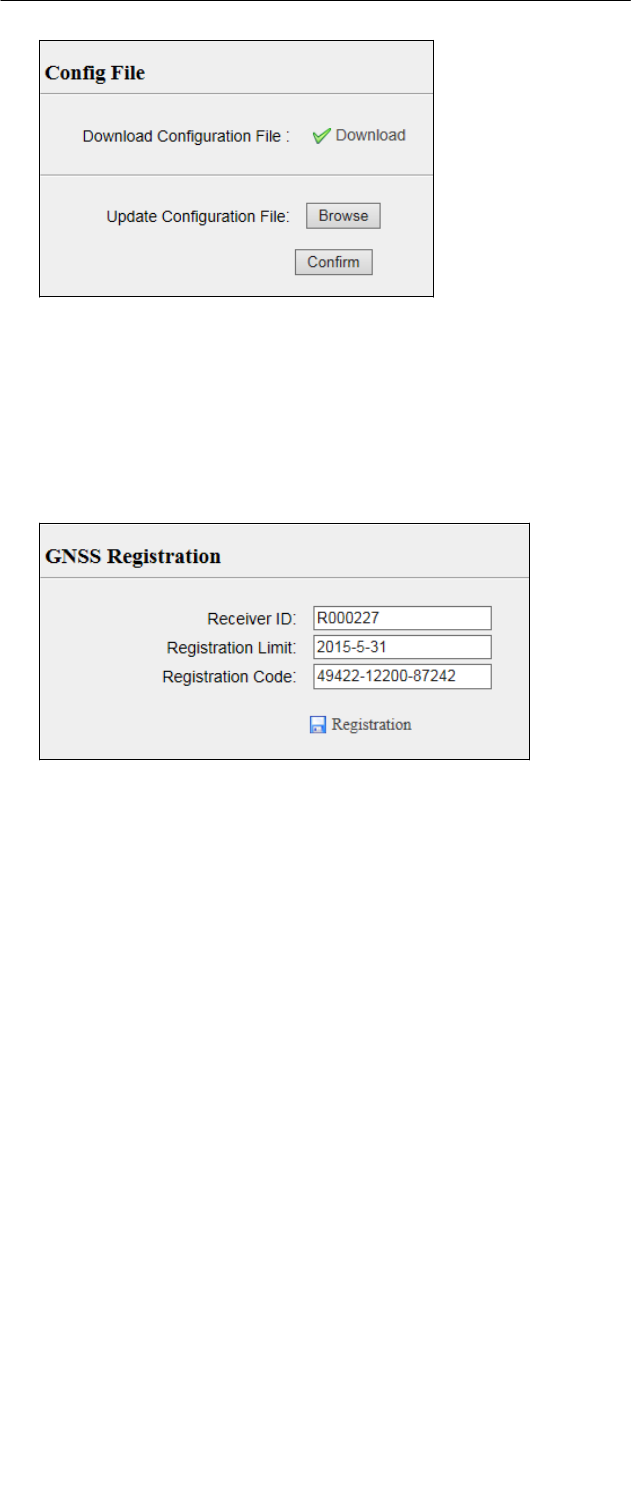
• Config File
In this submenu, users can download the configuration file by clicking
button and determine a saving path to download the
configuration file (.cfg file). Also, users can click the [Browse] button to
locate the existing configuration file click [Confirm] button to confirm
the selected file and start updating.
6.
Configuring
the
Receiver:
Other
Than
Keypad
and
Display
Page
45
X360 GIS Reference
Receiver
User
Guide
• GNSS Registration
Use this submenu to register the Receiver. Paste or enter the registration
code to the Registration Code field click [Registration] button to
complete the registration.

Page
46
X360 GIS Reference
Receiver
User
Guide
–
DEFAULT SETTING AND CONFIGURATION FILES
Most of the Receiver settings are stored in application files. The
default
application file, Default.cfg, is stored permanently in the
Receiver, and
contains the factory default settings for the X360 GIS
Receiver.
Whenever the Receiver is reset to its factory defaults, the current settings
(stored in the current configuration file, copy.cfg) are reset to the values in
the default application file.
The X360 GIS Receiver extends the use of configuration files to allow
simplified Receiver setting duplication in multiple Receivers. This is
sometimes referred to as Receiver cloning and is very useful when
preparing
a large group of Receivers for a field data collection campaign.
• DEFAULT RECEIVER SETTINGS
Function
Factory default values
SV Enable
All SVs enabled
General controls
Elevation mask
PDOP mask
0°
6°
Lemo port
Baud rate
Format
Flow control
9600
8-
None-
1
None
Log status
OFF
Differential data
OFF
Raw data
OFF
Ephemeris data
OFF
NMEA (GPGGA,
GPGSV)
OFF
position
Latitud
e
Longit
ude
Height
0°0’0.00000000’’
0°0’0.00000000’’
0.000
Antenna
Type
Measure
Method
Height
CHC Helical GNSS
Antenna
2.0000
(Meter)
Antenna Phase Center
• RESETTING THE RECEIVER TO FACTORY DEFAULTS
Log in the web page of the Receiver tap and unfold the Receiver Reset
menu tap the Receiver Reset submenu click the
button to the right of Back to Default Setting field.
Page
47
X360 GIS Reference
Receiver
User
Guide
7. Default Settings and Application Files
• USING CONFIGURATION FILES TO DUPLICATE RECEIVER SETTINGS
The X360 GIS Receiver allows the extensive use of application files in
order to retain a unique Receiver configuration. With this Receiver, you can
create a configuration file that includes most of the Receiver's unique
configuration settings. You can then update that configuration file onto one
or more other X360 GIS Receivers to quickly configure them to match
the
Receiver which creates that configuration file.
NOTE: The configuration file includes most of the configuration
settings except IP Address, IP Mask, Gateway and DNS Server.
This is called Receiver configuration cloning or cloning. Receiver cloning
greatly reduces the time required to prepare a large group of Receivers for
field operations.
Log in the web page of the Receiver tap and unfold the Firmware menu
tap the Config File submenu click the [Browse] button to locate the
existing configuration file click [Confirm] button to confirm the selected
file and start updating.

Page
48
X360 GIS Reference
Receiver
User
Guide
–
SPECIFICATIONS
This chapter describes the specifications for the X360 GIS Receiver.
Specifications are subject to change without notice.
• GNSS CHARACTERISTICS
Feature
Specification
Tracking
–
220 channels
• GPS: L1 C/A, L2C, L2E, L5
–
Pseudo-range measurement with high-
precision
multi-correlator
–
Very low noise carrier phase measurements with <1
mm
precision in a 1 Hz bandwidth
Real Time Kinematic (RTK)
Horizontal: 8 mm + 1 ppm
RMS
Vertical: 15 mm + 1
ppm RMS
Post Processing Static
Horizontal: 2.5 mm + 0.5 ppm
RMS
Vertical: 5 mm + 0.5 ppm
RMS
Initialization time
Typically < 10 s
Initialization reliability
Typically > 99.9%
• COMMUNICATION
Feature
Specification
RJ45 Jack
Ethernet
DB9 male
3-wire RS232, see C.I. CHC X360 Receiver COM 1 (10-pin LEMO
port)
definition for details
COM1 (10-pin LEMO
port)
8-wire RS232, see C.II. CHC X360 Receiver COM 2 (10-pin LEMO
port)
definition for details
COM2 (10-pin LEMO
port)
9-wire RS232, see C.III. CHC X360 Receiver db9 male
connector
definition for details
USB port
Type-A USB receptacle, operates in Host mode
Bluetooth
Fully integrated, fully sealed 2.4 GHz Bluetooth wireless technology
Protocols
Correction formats: CMR, CMR+, SCMR, RTCM2.3,
3.0
Observables: RT17, RT27, RTCM3.X
Position/Status I/O: NMEA-0183 V2.30 (GPGGA & GPGSV)

Page
49
X360 GIS Reference
Receiver
User
Guide
8.
Specifications
• PHYSICAL
Feature
Specification
Size
110 x 81 x 52 mm
Weight
490g (17.28 oz)
Humidity
100% condensation
Waterproof and
dust
proof
Tested to IP65; waterproof for temporary immersion to a depth of 1
m
(3.28 ft) for 30 minutes; dustproof
Shock
Designed to survive a 1.2 m (3.93 ft) drop onto concrete
• ELECTRICAL
Feature
Specification
Power consumption
2.5 W nominal, dependent on user settings
Internal
Integrated internal battery 7.4 V, 4500 mA-hr, Lithium-ion
Internal battery can operate as a UPS in the event of
external
power source outage
Internal battery will charge from the external power source
when
the internal battery is not fully charged
External
Power source supply (Internal / External) is hot swap capable in
the
event of power source removal or cut-off
Power input on Lemo ports is 12 V DC to 36 V DC external
power
input
Receiver will auto power on when connected to external
power
with voltage above 11 V
Operation time on
internal battery
Up to 10 hours continuous operation, dependent on user setting
• GENERAL
Feature
Specification
Receiver type
GIS Receiver
Antenna type
CHC A220GR GNSS Geodetic antenna or CHC C220GR GNSS
Choke
Ring antenna preferred.
Other models supported.
• DATA STORAGE

8.
Specifications
Page
50
X360 GIS Reference
Receiver
User
Guide
Feature
Specification
Internal storage
16 GB
External storage
Supporting USB drive or portable hard drive
Storage method
8-thread logging, circulating data logging
Data format
HCN, RINEX, original binary data
Data download
FTP push, online download, storage on an external USB devices

Page
51
X360 GIS Reference
Receiver
User
Guide
1.
UPGRADING THE RECEIVER FIRMWARE
The Receiver is supplied with the latest version of the Receiver firmware
already installed. If a later version of the firmware becomes available, use
the USB device to upgrade the firmware on your Receiver. For the latest
firmware resource, please consult your local CHC dealer.
You can also upgrade the Receiver through the web interface. The firmware
file required to upgrade the Receiver through the Web interface is located in
the folder where the user saves the file. The file type required is the format
update_X360_e_vXXXXX_bYYYYMMDD.bin where XXXXX represents the
version of firmware and YYYYMMDD represents the firmware encapsulation
date.
1.1. THE WINFLASH UTILITY
The WinFlash utility communicates with CHC products to perform various
functions including:
A.
load or verify GPS software of the mainboard
B.
update or verify the Receiver options
For more information, online help is also available when using the WinFlash
utility.
1.1.1. INSTALLING THE WINFLASH UTILITY
You can download the WinFlash utility from the Trimble website. This
self-extracting executable guides you through the software installation
process.
1.2. UPGRADING THE RECEIVER FIRMWARE
1.2.1. UPGRADING THROUGH USB PORT
1.
Copy the firmware file to the root directory of external storage device
such as USB drive, portable hard drive.
2.
Connect the external storage device with Receiver through USB port.
3.
Restart the Receiver and then the screen will prompt you whether
to
upgrade the firmware.
4.
Press OK button to upgrade the firmware.
5.
When the upgrading is completed, the Receiver will be restarted
and
the screen will prompt you whether to upgrade the firmware
again.
6.
Press one of the arrow keys to quit the upgrading and then remove the
external storage device.

Page
52
X360 GIS Reference
Receiver
User
Guide
6.1.
Upgrading the Receiver
Firmware
1.2.2. UPGRADING THROUGH A BROWSER
Please connect to the Receiver through a web browser according to 6.2.
Configuring through a web browser, and then refer to 6.2.1.10 F irmware
menu Firmware Update for detail operation steps.
NOTE: After the Receiver firmware upgrading, the IP information may
be changed. Please confirm the IP setting of the Receiver before
using
it.

Page
53
X360 GIS Reference
Receiver
User
Guide
–
TROUBLESHOOTING
Use this appendix to identify and solve common problems that may occur
during the use of the Receiver.
Please read this section before you contact CHC Technical Support.
• RECEIVER ISSUES
This section describes some possible Receiver issues, possible causes, and
how to solve them.
Issue
Possible cause
Solution
The Receiver
does
not turn
on.
External power is
too
low.
Check the charge on the external battery and, if
applicable,
check the fuse.
Internal power is
too
low.
Check the charge on the internal battery.
External power is
not
properly
connected.
Check that the Lemo connector is seated correctly and
that
the cable is secured to the Receiver.
Check for broken or bent pins in the connector.
Faulty power cable.
Check that you are using the correct cable for the
connection between Lemo port and external power
supply.
Check that the correct external power supply is
connected
to a particular Lemo port.
Check pinouts with a multimeter to ensure internal
wiring
is intact.
Receiver does
not
log data.
The Receiver is
tracking
fewer than
four
satellites.
Wait until the Receiver display shows that more than
four
satellites are being tracked.
The Receiver is
not
responding.
Receiver needs a
soft
reset.
Turn off the Receiver and then turn it back on again.
The
stati
on Receiver
is not
broadcasti
ng.
Port settings
between
Receiver
and radio are
incorrect.
Check the port settings for the Receiver by using the
Web
interface. Check that the radio ports are correctly
set up.
Faulty cable
between
Receiver
and radio.
Try a different cable.
Examine the ports for missing pins.
Use a multimeter to check pinouts.
No power to radio.
If the radio has its own power supply, check the charge
and
connections.
The Receiver is
not
receiving
satellite
signals
The GNSS antenna
cable
is loose.
Make sure that the GNSS antenna cable is tightly
seated in
the antenna connector on the GNSS antenna.
The cable is damaged.
Check the cable for any signs of damage. A damaged
cable
can inhibit signal detection from the antenna at
the
Receiver.

Page
54
X360 GIS Reference
Receiver
User
Guide
B. Troubleshooting
The GNSS antenna is
not
in clear line of
sight to
the sky.
Make sure that the GNSS antenna is located with a
clear
view of the sky.
Restart the Receiver as a last resort (turn off and then turn
it on again).

Page
55
X360 GIS Reference
Receiver
User
Guide
COMMUNICATION PORTS DEFINITION
CHC X360 Receiver DB9 MALE CONNECTOR DEFINITION
PI
N
Signal
Name
Description
1
Not Used
2
TXD
RS232-TX (transmit data through this pin)
3
RXD
RS232-RX (receive data through this pin)
4
Not Used
5
GND
External Power Ground
6
Not Used
7
Not Used
8
Not Used
9
Not Used

Page
56
X360 GIS Reference
Receiver
User
Guide
D.
Glossary
GLOSSARY
base station
Also called station. A base station in construction, is a Receiver placed at a
known point on a jobsite that tracks the same satellites as an RTK rover, and
provides a real-time differential correction message stream through radio to
the
rover, to obtain centimeter level positions on a continuous real-time basis.
A base
station can also be a part of a virtual station network, or a
location at which GPS
observations are collected over a period of time, for
subsequent postprocessing to
obtain the most accurate position for the
location.
carrier
A radio wave having at least one characteristic (such as frequency, amplitude,
or
phase) that can be varied from a known value by modulation.
carrier frequency
The frequency of the unmodulated fundamental output of a radio transmitter.
The
GPS L1 carrier frequency is 1575.42 MHz.
carrier phase
The time taken for the L1 or L2 carrier signal generated by the satellite to
reach
the GPS Receiver. Measuring the number of carrier waves between the
satellite
and Receiver is a very accurate method of calculating the distance
between them.
C
M
R
C
M
R+
Compact Measurement Record. A real-time message format developed by
Trimble
for broadcasting corrections to other Trimble mainboard Receivers.
CMR is a more
efficient alternative to RTCM.
DGPS
See real-time differential GPS.
differen
tial
correcti
on
Differential correction is the process of correcting GPS data collected on a
rover
with data collected simultaneously at a base station. Because the base
station is
on a known location, any errors in data collected at the base
station can be
measured, and the necessary corrections applied to the rover
data.
Differential correction can be done in real-time, or after the data has
been
collected by postprocessing.
Differential GPS
See real-time differential GPS.
DOP
Dilution of Precision. A measure of the quality of GPS positions, based on the
geometry of the satellites used to compute the positions. When satellites are
widely spaced relative to each other, the DOP value is lower, and position
accuracy
is greater. When satellites are close together in the sky, the DOP is
higher and GPS
positions may contain a greater level of error.
PDOP (Position DOP) indicates the three-dimensional geometry of the
satellites.
Other DOP values include HDOP (Horizontal DOP) and VDOP (Vertical
DOP), which
indicate the accuracy of horizontal measurements (latitude and
longitude) and
vertical measurements respectively. PDOP is related to HDOP
and VDOP as
follows:
PDOP² = HDOP² + VDOP²
dual-
frequency
GPS
A type of Receiver that uses both L1 and L2 signals from GPS satellites. A
dual-frequency Receiver can compute more precise position fixes over
longer
distances and under more adverse conditions because it
compensates for
ionospheric delays.
elevation mask
The angle below which the Receiver will not track satellites. Normally set to
10
degrees to avoid interference problems caused by buildings and trees,
and
multipath errors.

Page
57
X360 GIS Reference
Receiver
User
Guide
D.
Glossary
ephemeri
s /
ephemerid
es
A list of predicted (accurate) positions or locations of satellites as a function
of
time. A set of numerical parameters that can be used to determine a
satellite’s
position.
Available as broadcast ephemeris or as postprocessed precise ephemeris.
epoch
The measurement interval of a GPS Receiver. The epoch varies according to the
measurement type: for real-time measurement it is set at one second; for
postprocessed measurement it can be set to a rate of between one second and
one minute. For example, if data is measured every 15 seconds, loading data
using
30-second epochs means loading every alternate measurement.
firmware
The program inside the Receiver that controls Receiver operations and
hardware.
GNSS
Global Navigation Satellite System.
GSOF
General Serial Output Format. A Trimble proprietary message format.
HDOP
Horizontal Dilution of Precision. HDOP is a DOP value that indicates the
accuracy
of horizontal measurements. Other DOP values include VDOP
(vertical DOP) and
PDOP (Position DOP).
Using a maximum HDOP is ideal for situations where vertical precision is not
particularly important, and your position yield would be decreased by the
vertical
component of the PDOP ( for example, if you are collecting data under
canopy).
L1
The primary L-band carrier used by GPS satellites to transmit satellite data.
L2
The secondary L-band carrier used by GPS satellites to transmit satellite data.
L5
The third L-band carrier used by GPS satellites to transmit satellite data. L5
will
provide a higher power level than the other carriers. As a result,
acquiring and
tracking weak signals will be easier.
multi-
frequency
GPS
A type of Receiver that uses multiple carrier phase measurements (L1, L2, and
L5)
from different satellite frequencies.
multipath
Interference, similar to ghosts on a television screen that occurs when GPS
signals
arrive at an antenna having traversed different paths. The signal
traversing the
longer path yields a larger pseudorange estimate and increases
the error. Multiple
paths can arise from reflections off the ground or off
structures near the antenna.
NMEA
National Marine Electronics Association. NMEA 0183 defines the standard for
interfacing marine electronic navigational devices. This standard defines a
number
of 'strings' referred to as NMEA strings that contain navigational details
such as
positions. Most CHC GPS Receivers can output positions as NMEA
strings.
PDOP
Position Dilution of Precision. PDOP is a DOP value that indicates the accuracy of

Page
58
X360 GIS Reference
Receiver
User
Guide
D.
Glossary
three-dimensional measurements. Other DOP values include VDOP (vertical
DOP)
and HDOP (Horizontal Dilution of Precision).
Using a maximum PDOP value is ideal for situations where both vertical
and
horizontal precision are important.
postprocessing
Postprocessing is the processing of satellite data after it has been collected,
in
order to eliminate error. This involves using computer software to compare
data
from the rover with data collected at the base station.
real-
time
differen
tial
GPS
Also known as real-time differential correction or DGPS. Real-time differential
GPS
is the process of correcting GPS data as you collect it. Corrections are
calculated at
a base station and then sent to the Receiver through a radio link.
As the rover
receives the position it applies the corrections to give you a very
accurate position
in the field.
Most real-time differential correction methods apply corrections to code
phase
positions. RTK uses carrier phase measurements.
While DGPS is a generic term, its common interpretation is that it entails the
use
of single-frequency code phase data sent from a GPS base station to a
rover GPS
Receiver to provide sub-meter position accuracy. The rover
Receiver can be at a
long range (greater than 100 km (62 miles)) from the
base station.
station
See base station
rover
A rover is any mobile GPS Receiver that is used to collect or update data in
the
field, typically at an unknown location.
RTCM
Radio Technical Commission for Maritime Services. A commission established
to
define a differential data link for the real-time differential correction of
roving GPS
Receivers. There are three versions of RTCM correction messages.
All CHC GPS
Receivers use Version 2 protocol for single-frequency DGPS type
corrections.
Carrier phase corrections are available on Version 2, or on the newer Version
3
RTCM protocol, which is available on certain CHC dual-frequency
Receivers. The
Version 3 RTCM protocol is more compact but is not as
widely supported as
Version 2.
RTK
Real-time kinematic. A real-time differential GPS method that uses carrier
phase
measurements for greater accuracy.
signal-to-
noise
ratio
SNR. The signal strength of a satellite is a measure of the information content
of
the signal, relative to the signal’s noise. The typical SNR of a satellite at 30°
elevation is between 47 and 50 dBHz. The quality of a GPS position is
degraded if
the SNR of one or more satellites in the constellation falls below
39.
skyplot
The satellite skyplot confirms reception of a differentially corrected GPS signal
and
displays the number of satellites tracked by the GPS Receiver, as well as
their
relative positions.
SNR
See signal-to-noise ratio
UTC
Universal Time Coordinated. A time standard based on local solar mean time
at
the Greenwich meridian.
VRS
Virtual Station. A VRS system consists of GNSS hardware, software, and

Page
59
X360 GIS Reference
Receiver
User
Guide
D.
Glossary
communication links. It uses data from a network of stations to provide
corrections to each rover that are more accurate than corrections from a
single
base station.
To start using VRS corrections, the rover sends its position to the VRS server.
The
VRS server uses the station data to model systematic errors (such as
ionospheric
noise) at the rover position. It then sends RTCM or CMR correction
messages back
to the rover.

Battery Charging:
Please use the applicable adapter with the required specifications to charge the X360
GIS Receiver.
Please plug in the adapter and connect the DC port to X360 GIS Receiver.
Specifications of the adaptor:
input 100~240V, 50/60Hz, 2.0A
Output 12V. 1.5A
GIS Receiver placed in the fixed outdoor use, will not carry.
CHC - Shanghai Huace Navigation Technology LTD.
Building C, 599 Gaojing Road,
Qingpu District, Shanghai, China
Tel: +86 21 542 60 273
Fax: +86 21 649 50 963
Email: sales@chcnav.com | support@chcnav.com
Website: www.chcnav.com
FCC Statement
1. This device complies with Part 15 of the FCC Rules. Operation is subject to the following two conditions:
(1) This device may not cause harmful interference.
(2) This device must accept any interference received, including interference that may cause undesired operation.
2. Changes or modifications not expressly approved by the party responsible for compliance could void the user's authority
to operate the equipment.
NOTE:
This equipment has been tested and found to comply with the limits for a Class B digital device, pursuant to Part 15 of the
FCC Rules. These limits are designed to provide reasonable protection against harmful interference in a residential
installation.
This equipment generates uses and can radiate radio frequency energy and, if not installed and used in accordance with the
instructions, may cause harmful interference to radio communications. However, there is no guarantee that interference will
not occur in a particular installation. If this equipment does cause harmful interference to radio or television reception,
which can be determined by turning the equipment off and on, the user is encouraged to try to correct the interference by
one or more of the following measures:
Reorient or relocate the receiving antenna.
Increase the separation between the equipment and receiver.
Connect the equipment into an outlet on a circuit different from that to which the receiver is connected.
Consult the dealer or an experienced radio/TV technician for help.
The distance between user and products should be no less than 20cm