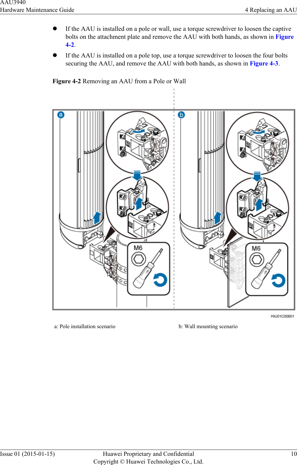
Huawei Technologies AAU3940 Active Antenna Unit User Manual Hardware Maintenance Guide
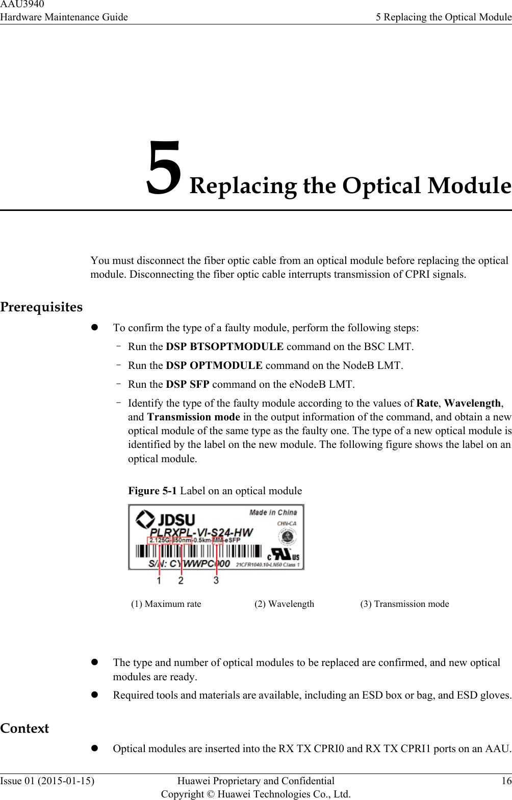
Huawei Technologies Co.,Ltd Active Antenna Unit Hardware Maintenance Guide
Contents
- 1. HardwareMaintenanceGuide.pdf
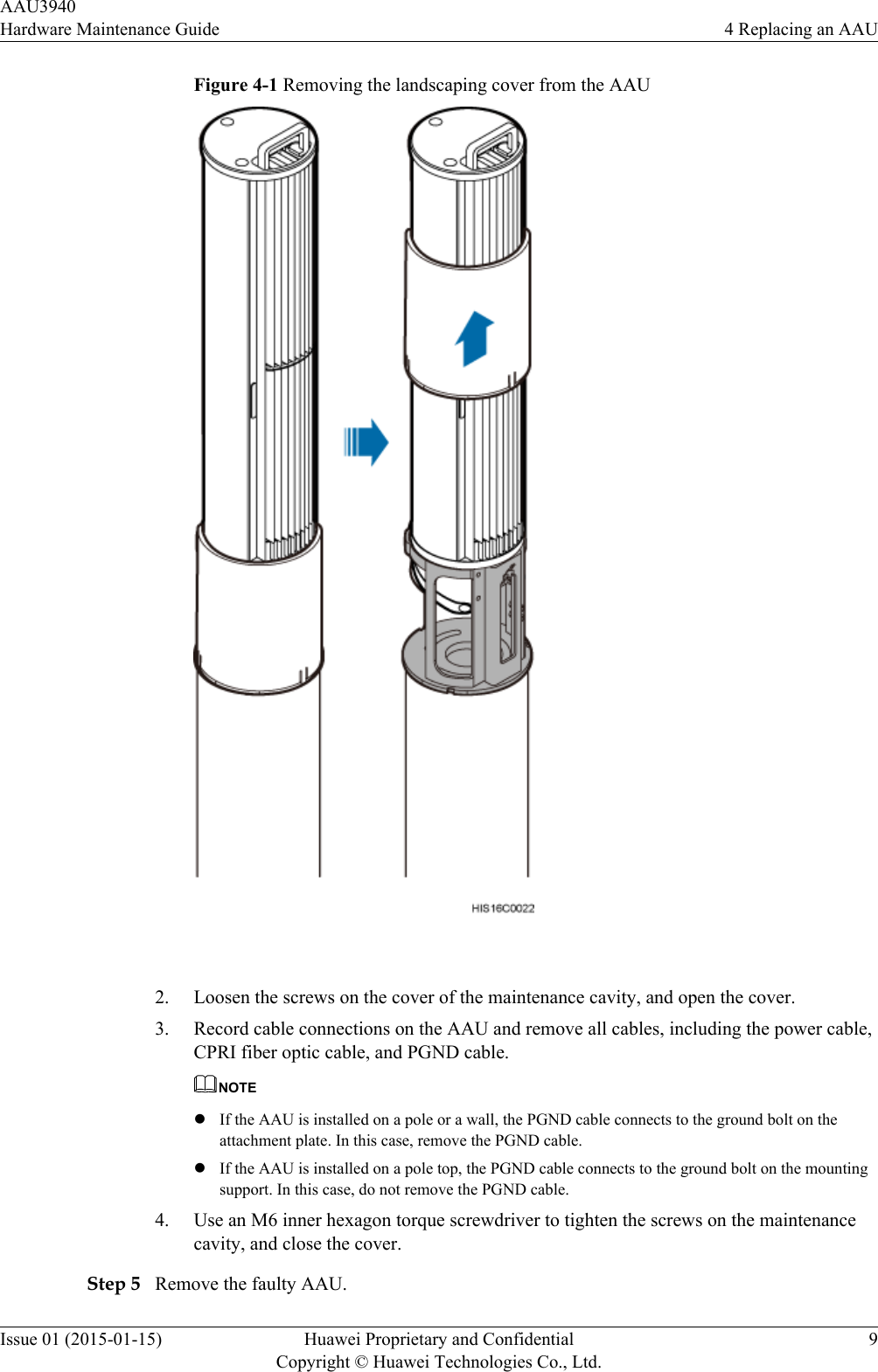
- 2. InstallationGuide.pdf
- 3. UserManual_safety.pdf
HardwareMaintenanceGuide.pdf
![Convention DescriptionItalic Book titles are in italics.Courier New Examples of information displayed on the screen are inCourier New. Command ConventionsThe command conventions that may be found in this document are defined as follows.Convention DescriptionBoldface The keywords of a command line are in boldface.Italic Command arguments are in italics.[ ] Items (keywords or arguments) in brackets [ ] are optional.{ x | y | ... } Optional items are grouped in braces and separated byvertical bars. One item is selected.[ x | y | ... ] Optional items are grouped in brackets and separated byvertical bars. One item is selected or no item is selected.{ x | y | ... }*Optional items are grouped in braces and separated byvertical bars. A minimum of one item or a maximum of allitems can be selected.[ x | y | ... ]*Optional items are grouped in brackets and separated byvertical bars. Several items or no item can be selected. GUI ConventionsThe GUI conventions that may be found in this document are defined as follows.Convention DescriptionBoldface Buttons, menus, parameters, tabs, window, and dialog titlesare in boldface. For example, click OK.>Multi-level menus are in boldface and separated by the ">"signs. For example, choose File > Create > Folder. Keyboard OperationsThe keyboard operations that may be found in this document are defined as follows.AAU3940Hardware Maintenance Guide About This DocumentIssue 01 (2015-01-15) Huawei Proprietary and ConfidentialCopyright © Huawei Technologies Co., Ltd.iv](https://usermanual.wiki/Huawei-Technologies/AAU3940.HardwareMaintenanceGuide-pdf/User-Guide-2940214-Page-5.png)