Huawei Technologies AAU3940 Active Antenna Unit User Manual Hardware Maintenance Guide
Huawei Technologies Co.,Ltd Active Antenna Unit Hardware Maintenance Guide
Contents
- 1. HardwareMaintenanceGuide.pdf
- 2. InstallationGuide.pdf
- 3. UserManual_safety.pdf
HardwareMaintenanceGuide.pdf
AAU3940
Hardware Maintenance Guide
Issue 01
Date 2015-01-15
HUAWEI TECHNOLOGIES CO., LTD.

Copyright © Huawei Technologies Co., Ltd. 2015. All rights reserved.
No part of this document may be reproduced or transmitted in any form or by any means without prior written
consent of Huawei Technologies Co., Ltd.
Trademarks and Permissions
and other Huawei trademarks are trademarks of Huawei Technologies Co., Ltd.
All other trademarks and trade names mentioned in this document are the property of their respective holders.
Notice
The purchased products, services and features are stipulated by the contract made between Huawei and the
customer. All or part of the products, services and features described in this document may not be within the
purchase scope or the usage scope. Unless otherwise specified in the contract, all statements, information,
and recommendations in this document are provided "AS IS" without warranties, guarantees or representations
of any kind, either express or implied.
The information in this document is subject to change without notice. Every effort has been made in the
preparation of this document to ensure accuracy of the contents, but all statements, information, and
recommendations in this document do not constitute a warranty of any kind, express or implied.
Huawei Technologies Co., Ltd.
Address: Huawei Industrial Base
Bantian, Longgang
Shenzhen 518129
People's Republic of China
Website: http://www.huawei.com
Email: support@huawei.com
Issue 01 (2015-01-15) Huawei Proprietary and Confidential
Copyright © Huawei Technologies Co., Ltd.
i
About This Document
Overview
This document describes routine maintenance for an AAU3940 such as equipment maintenance
and power-on and power-off operations. It also describes how to replace the AAU, modules in
it, and optical modules.
Product Version
The following table lists the product versions related to this document.
Product Name Solution Version Product Version
DBS3900 lSRAN10.0 and later
lRAN17.0 and later
leRAN8.0 and later
V100R010C00 and later
Intended Audience
This document is intended for:
lBase station installation personnel
lSystem engineer
lSite maintenance personnel
Organization
1 Changes in AAU3940 Hardware Maintenance Guide
This chapter describes changes in AAU3940 Hardware Maintenance Guide.
2 Routine Hardware Maintenance Items
Routine hardware maintenance for an AAU improves reliability of the AAU. You are advised
to perform routine hardware maintenance yearly.
3 Powering On and Powering Off an AAU
AAU3940
Hardware Maintenance Guide About This Document
Issue 01 (2015-01-15) Huawei Proprietary and Confidential
Copyright © Huawei Technologies Co., Ltd.
ii
This section describes the process and precautions for powering on and powering off an AAU.
4 Replacing an AAU
This section describes how to replace a faulty AAU. Replacing an AAU interrupts all the services
carried by the AAU and causes alarms.
5 Replacing the Optical Module
You must disconnect the fiber optic cable from an optical module before replacing the optical
module. Disconnecting the fiber optic cable interrupts transmission of CPRI signals.
Conventions
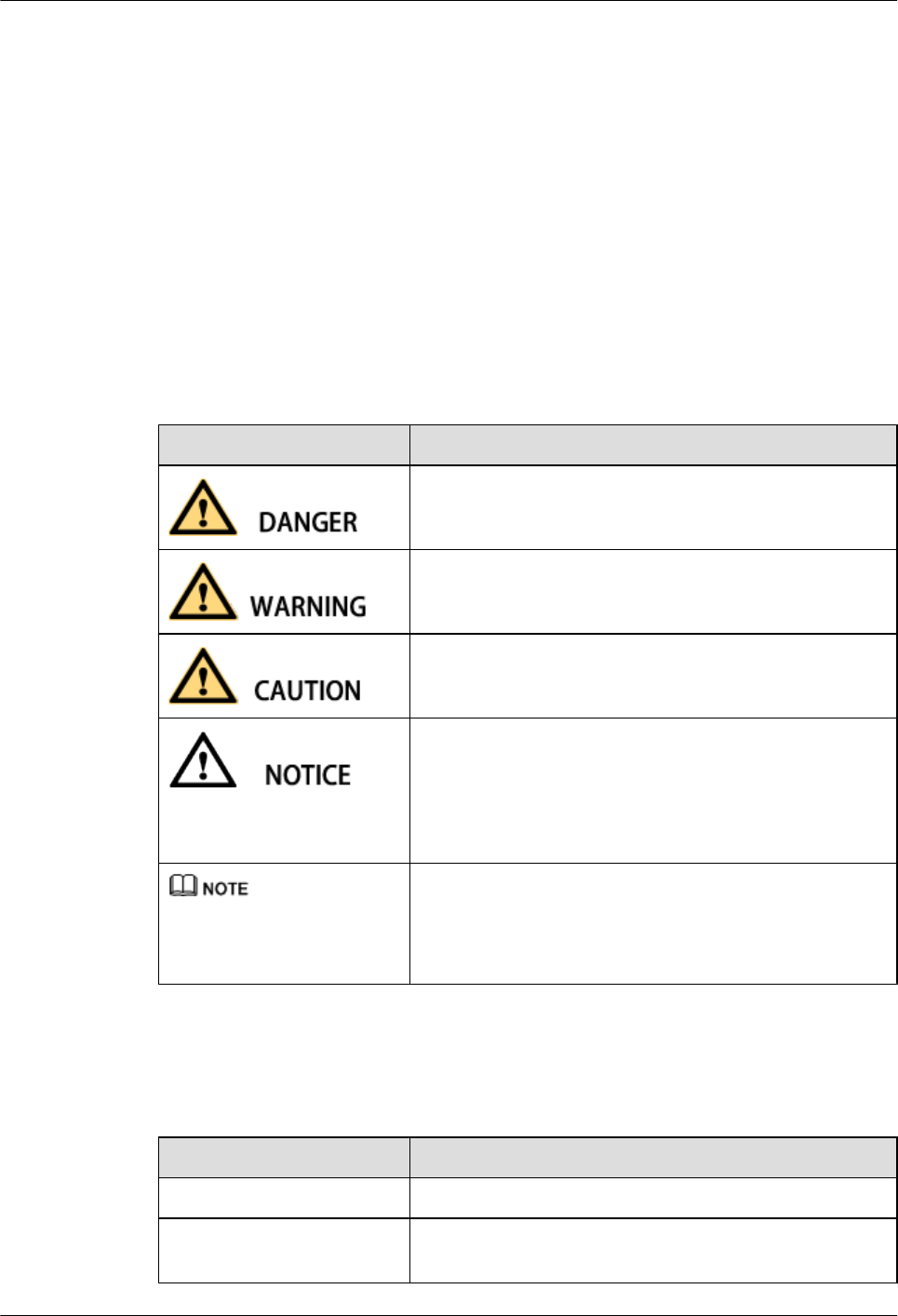
Symbol Conventions
The symbols that may be found in this document are defined as follows.
Symbol Description
Indicates an imminently hazardous situation which, if not
avoided, will result in death or serious injury.
Indicates a potentially hazardous situation which, if not
avoided, could result in death or serious injury.
Indicates a potentially hazardous situation which, if not
avoided, may result in minor or moderate injury.
Indicates a potentially hazardous situation which, if not
avoided, could result in equipment damage, data loss,
performance deterioration, or unanticipated results.
NOTICE is used to address practices not related to personal
injury.
Calls attention to important information, best practices and
tips.
NOTE is used to address information not related to personal
injury, equipment damage, and environment deterioration.
General Conventions
The general conventions that may be found in this document are defined as follows.
Convention Description
Times New Roman Normal paragraphs are in Times New Roman.
Boldface Names of files, directories, folders, and users are in
boldface. For example, log in as user root.
AAU3940
Hardware Maintenance Guide About This Document
Issue 01 (2015-01-15) Huawei Proprietary and Confidential
Copyright © Huawei Technologies Co., Ltd.
iii
Convention Description
Italic Book titles are in italics.
Courier New Examples of information displayed on the screen are in
Courier New.
Command Conventions
The command conventions that may be found in this document are defined as follows.
Convention Description
Boldface The keywords of a command line are in boldface.
Italic Command arguments are in italics.
[ ] Items (keywords or arguments) in brackets [ ] are optional.
{ x | y | ... } Optional items are grouped in braces and separated by
vertical bars. One item is selected.
[ x | y | ... ] Optional items are grouped in brackets and separated by
vertical bars. One item is selected or no item is selected.
{ x | y | ... }*Optional items are grouped in braces and separated by
vertical bars. A minimum of one item or a maximum of all
items can be selected.
[ x | y | ... ]*Optional items are grouped in brackets and separated by
vertical bars. Several items or no item can be selected.
GUI Conventions
The GUI conventions that may be found in this document are defined as follows.
Convention Description
Boldface Buttons, menus, parameters, tabs, window, and dialog titles
are in boldface. For example, click OK.
>Multi-level menus are in boldface and separated by the ">"
signs. For example, choose File > Create > Folder.
Keyboard Operations
The keyboard operations that may be found in this document are defined as follows.
AAU3940
Hardware Maintenance Guide About This Document
Issue 01 (2015-01-15) Huawei Proprietary and Confidential
Copyright © Huawei Technologies Co., Ltd.
iv
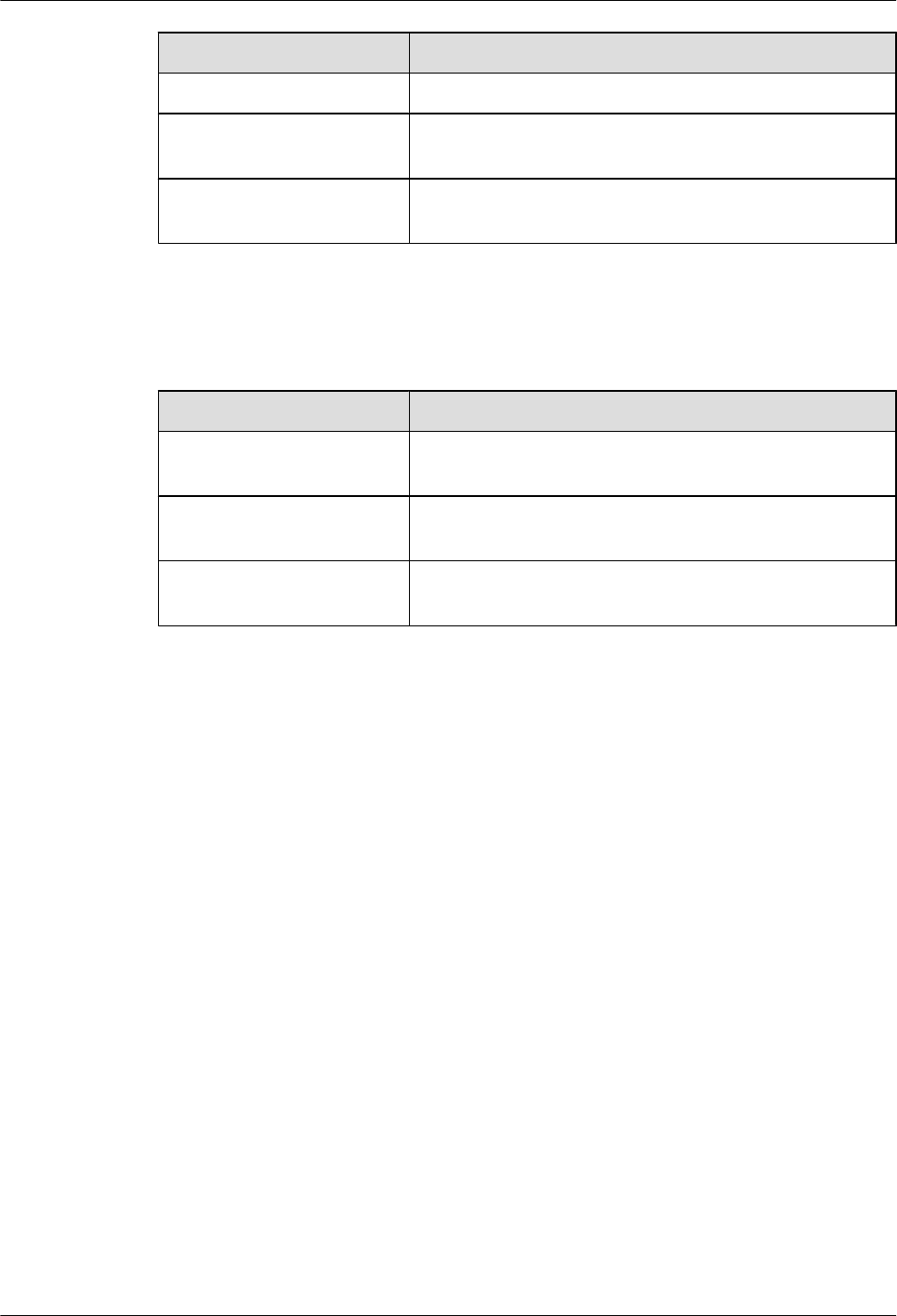
Format Description
Key Press the key. For example, press Enter and press Tab.
Key 1+Key 2 Press the keys concurrently. For example, pressing Ctrl+Alt
+A means the three keys should be pressed concurrently.
Key 1, Key 2 Press the keys in turn. For example, pressing Alt, A means
the two keys should be pressed in turn.
Mouse Operations
The mouse operations that may be found in this document are defined as follows.
Action Description
Click Select and release the primary mouse button without moving
the pointer.
Double-click Press the primary mouse button twice continuously and
quickly without moving the pointer.
Drag Press and hold the primary mouse button and move the
pointer to a certain position.
AAU3940
Hardware Maintenance Guide About This Document
Issue 01 (2015-01-15) Huawei Proprietary and Confidential
Copyright © Huawei Technologies Co., Ltd.
v

Contents
About This Document.....................................................................................................................ii
1 Changes in AAU3940 Hardware Maintenance Guide............................................................1
2 Routine Hardware Maintenance Items.....................................................................................2
3 Powering On and Powering Off an AAU.................................................................................4
3.1 Powering on an AAU.....................................................................................................................................................5
3.2 Powering off an AAU.....................................................................................................................................................6
4 Replacing an AAU.........................................................................................................................8
5 Replacing the Optical Module..................................................................................................16
AAU3940
Hardware Maintenance Guide Contents
Issue 01 (2015-01-15) Huawei Proprietary and Confidential
Copyright © Huawei Technologies Co., Ltd.
vi
1 Changes in AAU3940 Hardware
Maintenance Guide
This chapter describes changes in AAU3940 Hardware Maintenance Guide.
01 (2015-01-15)
This is the first commercial release.
Compared with issue Draft A (2014-10-30), no information is added to or deleted from this issue.
Compared with issue Draft A (2014-10-30), this issue includes the following changes.
Topic Change Description
Entire document Some figure updates caused by the structure
modification of the AAU.
Draft A (2013-10-30)
This is a draft.
AAU3940
Hardware Maintenance Guide 1 Changes in AAU3940 Hardware Maintenance Guide
Issue 01 (2015-01-15) Huawei Proprietary and Confidential
Copyright © Huawei Technologies Co., Ltd.
1
2 Routine Hardware Maintenance Items
Routine hardware maintenance for an AAU improves reliability of the AAU. You are advised
to perform routine hardware maintenance yearly.
DANGER
While working at heights, be careful not to drop any tools, equipment, or other objects. Falling
objects may cause serious injury or death. Always wear a helmet and avoid standing in the danger
area.
The items in the following checklist are not mandatory but strongly recommended.
Table 2-1 AAU routine hardware maintenance items
No. Item
1All AAUs are intact and securely installed, with all modules in the AAUs securely
installed.
2 All RF cables are free from wear, cuts, cracks, or other damage.
3 All RF cable connectors are sealed and waterproofed properly.
4 All RF cable conduits are in good condition.
5 All power cables are free from wear, cuts, cracks, or other damage.
6 All power cable connectors are in good condition.
7 All power cable conduits are in good condition.
8 All shield layers of power cables are in good condition.
9 All power cables are sealed properly.
10 All CPRI fiber optic cables are free from wear, cuts, cracks, or other damage.
11 All screws on the cover plate of the maintenance cavity are tightened.
AAU3940
Hardware Maintenance Guide 2 Routine Hardware Maintenance Items
Issue 01 (2015-01-15) Huawei Proprietary and Confidential
Copyright © Huawei Technologies Co., Ltd.
2

No. Item
12 All RET cables (optional) are free from wear, cuts, cracks, or other damage.
13 All RET cable (optional) connectors are sealed properly.
If any of the statements in the checklist cannot be complied with, perform the following
corrective actions:
1. Tighten all connections.
2. Report any other faults found during the checking, because further repairs on towers can
be performed only by trained and technically-qualified field engineers.
AAU3940
Hardware Maintenance Guide 2 Routine Hardware Maintenance Items
Issue 01 (2015-01-15) Huawei Proprietary and Confidential
Copyright © Huawei Technologies Co., Ltd.
3

3 Powering On and Powering Off an AAU
About This Chapter
This section describes the process and precautions for powering on and powering off an AAU.
3.1 Powering on an AAU
This section describes the procedure and precautions for powering on an AAU.
3.2 Powering off an AAU
An AAU can be powered off in two ways: normal power-off and emergency power-off. You
must power off the AAU in a normal situation such as moving the equipment or anticipating a
territorial blackout. You must also power off the AAU in an emergency such as a fire, smoke,
or water damage.
AAU3940
Hardware Maintenance Guide 3 Powering On and Powering Off an AAU
Issue 01 (2015-01-15) Huawei Proprietary and Confidential
Copyright © Huawei Technologies Co., Ltd.
4
3.1 Powering on an AAU
This section describes the procedure and precautions for powering on an AAU.
Context
DANGER
lBefore powering on a base station, check that the positive and negative wires of all power
cables are correctly connected. Any incorrect power cable connection may cause damage to
equipment or unexpected injuries of human body.
lExercise caution when performing a power-on check, which involves high voltage
operations. Direct contact with the input voltage or indirect contact with the input voltage
using a damp object may be fatal.
NOTICE
lAfter unpacking the RU, you must power on it within 24 hours. If you power off the RU for
maintenance, you must restore power to the RU within 24 hours.
lKeep a minimum of 7.35 m (24.11 ft) away from the front of the AAU after the RU is powered
on and the AAU starts working.
Process
The following figure shows the process of powering on an AAU.
AAU3940
Hardware Maintenance Guide 3 Powering On and Powering Off an AAU
Issue 01 (2015-01-15) Huawei Proprietary and Confidential
Copyright © Huawei Technologies Co., Ltd.
5
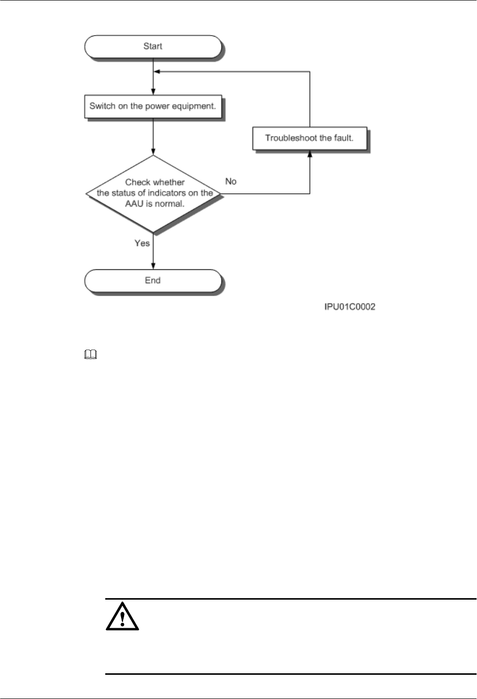
Figure 3-1 Process of powering on an AAU
NOTE
lThe normal input voltage of an AAU is 220 V AC and should range from 200 V AC to 240 V AC.
lWhen an AAU is working properly, the RUN indicator is blinking (on for 1s and off for 1s), and the ALM
indicator is steady off. For details about indicators, see AAU3940 Hardware Description.
3.2 Powering off an AAU
An AAU can be powered off in two ways: normal power-off and emergency power-off. You
must power off the AAU in a normal situation such as moving the equipment or anticipating a
territorial blackout. You must also power off the AAU in an emergency such as a fire, smoke,
or water damage.
Procedure
lNormal power-off
1. Set the corresponding circuit breaker on the power equipment for the AAU to OFF.
lEmergency power-off
NOTICE
Emergency power-off may damage the AAU. Therefore, do not perform an emergency
power-off in normal cases.
AAU3940
Hardware Maintenance Guide 3 Powering On and Powering Off an AAU
Issue 01 (2015-01-15) Huawei Proprietary and Confidential
Copyright © Huawei Technologies Co., Ltd.
6

1. Shut off the external input power of the power equipment for the AAU.
2. If time permits, set the corresponding circuit breaker on the power equipment for the
AAU to OFF.
----End
AAU3940
Hardware Maintenance Guide 3 Powering On and Powering Off an AAU
Issue 01 (2015-01-15) Huawei Proprietary and Confidential
Copyright © Huawei Technologies Co., Ltd.
7
4 Replacing an AAU
This section describes how to replace a faulty AAU. Replacing an AAU interrupts all the services
carried by the AAU and causes alarms.
Prerequisites
lThe following tools and materials are available: an ESD wrist strap or a pair of ESD gloves,
a flat-head screwdriver, a Phillips screwdriver, a torque screwdriver, a hex key, and an ESD
box or bag.
lThe new component is intact, and its hardware version is the same as that of the component
to be replaced.
Procedure
Step 1 Put on an ESD wrist strap or ESD gloves.
NOTICE
Take proper ESD protection measures, for example, put on an ESD wrist strap or ESD gloves,
to prevent electrostatic damage to the boards, modules, or electronic components.
Step 2 Instruct the U2000 administrator to block the faulty AAU by running the BLK BRD command.
Step 3 Power off the AAU. For detailed operations, see 3.2 Powering off an AAU.
Step 4 Remove cables from the faulty AAU.
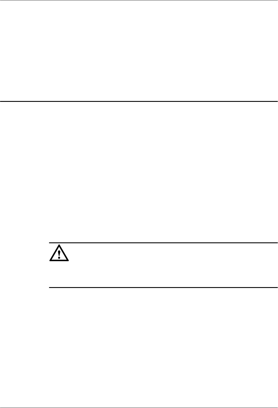
1. Optional: If the AAU is installed on a pole top, remove the landscaping cover, as shown
in the following figure. Skip this step if the AAU is installed on a pole or wall.
AAU3940
Hardware Maintenance Guide 4 Replacing an AAU
Issue 01 (2015-01-15) Huawei Proprietary and Confidential
Copyright © Huawei Technologies Co., Ltd.
8
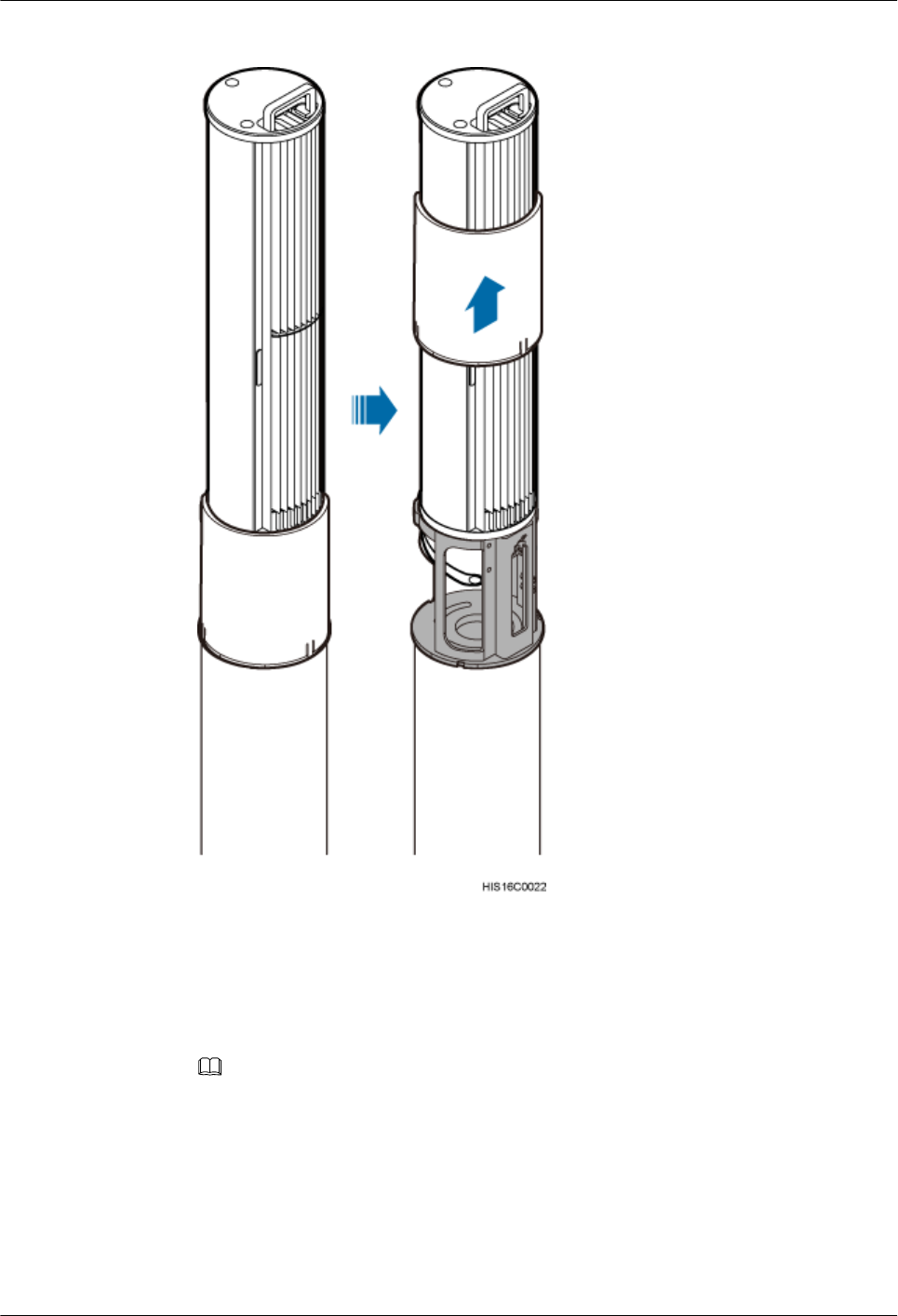
Figure 4-1 Removing the landscaping cover from the AAU
2. Loosen the screws on the cover of the maintenance cavity, and open the cover.
3. Record cable connections on the AAU and remove all cables, including the power cable,
CPRI fiber optic cable, and PGND cable.
NOTE
lIf the AAU is installed on a pole or a wall, the PGND cable connects to the ground bolt on the
attachment plate. In this case, remove the PGND cable.
lIf the AAU is installed on a pole top, the PGND cable connects to the ground bolt on the mounting
support. In this case, do not remove the PGND cable.
4. Use an M6 inner hexagon torque screwdriver to tighten the screws on the maintenance
cavity, and close the cover.
Step 5 Remove the faulty AAU.
AAU3940
Hardware Maintenance Guide 4 Replacing an AAU
Issue 01 (2015-01-15) Huawei Proprietary and Confidential
Copyright © Huawei Technologies Co., Ltd.
9
lIf the AAU is installed on a pole or wall, use a torque screwdriver to loosen the captive
bolts on the attachment plate and remove the AAU with both hands, as shown in Figure
4-2.
lIf the AAU is installed on a pole top, use a torque screwdriver to loosen the four bolts
securing the AAU, and remove the AAU with both hands, as shown in Figure 4-3.
Figure 4-2 Removing an AAU from a Pole or Wall
a: Pole installation scenario b: Wall mounting scenario
AAU3940
Hardware Maintenance Guide 4 Replacing an AAU
Issue 01 (2015-01-15) Huawei Proprietary and Confidential
Copyright © Huawei Technologies Co., Ltd.
10

Figure 4-3 Removing an AAU from a Pole Top
Step 6 Install a new AAU.
lIn the pole installation or wall mounting scenario:
1. Place the attachment plate on the maintenance cavity of the AAU, and use a torque
screwdriver to tighten the screws to 7 N·m (61.95 lbf·in.), as shown in Figure 4-4.
2. Insert the attachment plate at the bottom of the AAU to the dovetail groove on the
mounting bracket, and use a torque screwdriver to tighten the captive screws to 7 N·m
(61.95 lbf·in.), as shown in Figure 4-5.
AAU3940
Hardware Maintenance Guide 4 Replacing an AAU
Issue 01 (2015-01-15) Huawei Proprietary and Confidential
Copyright © Huawei Technologies Co., Ltd.
11
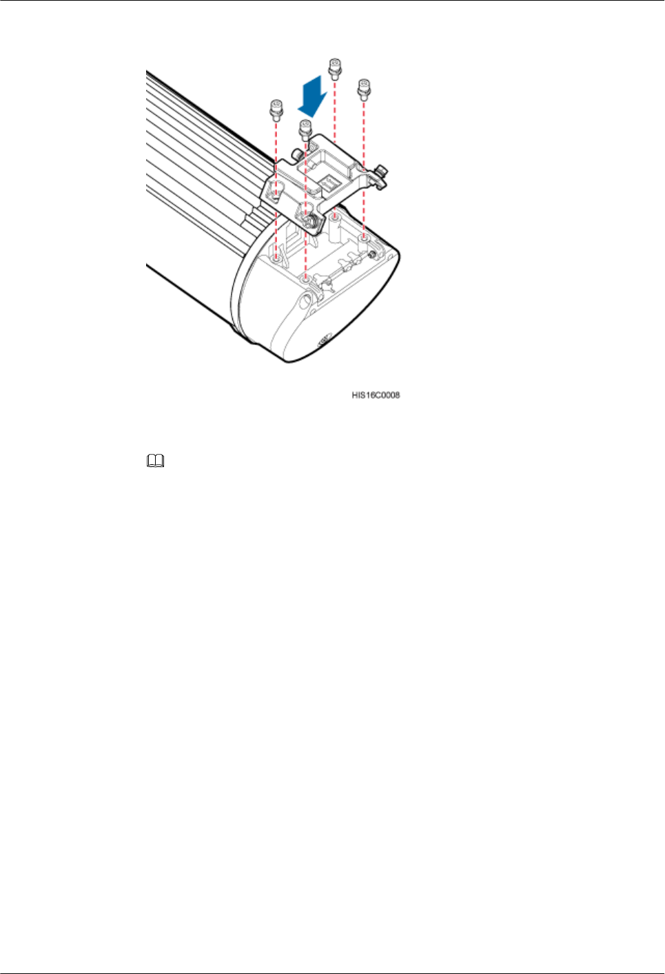
Figure 4-4 Installing the attachment plate
NOTE
The following figure shows the installation in the wall mounting scenario, installing an AAU on a pole is
the same.
AAU3940
Hardware Maintenance Guide 4 Replacing an AAU
Issue 01 (2015-01-15) Huawei Proprietary and Confidential
Copyright © Huawei Technologies Co., Ltd.
12
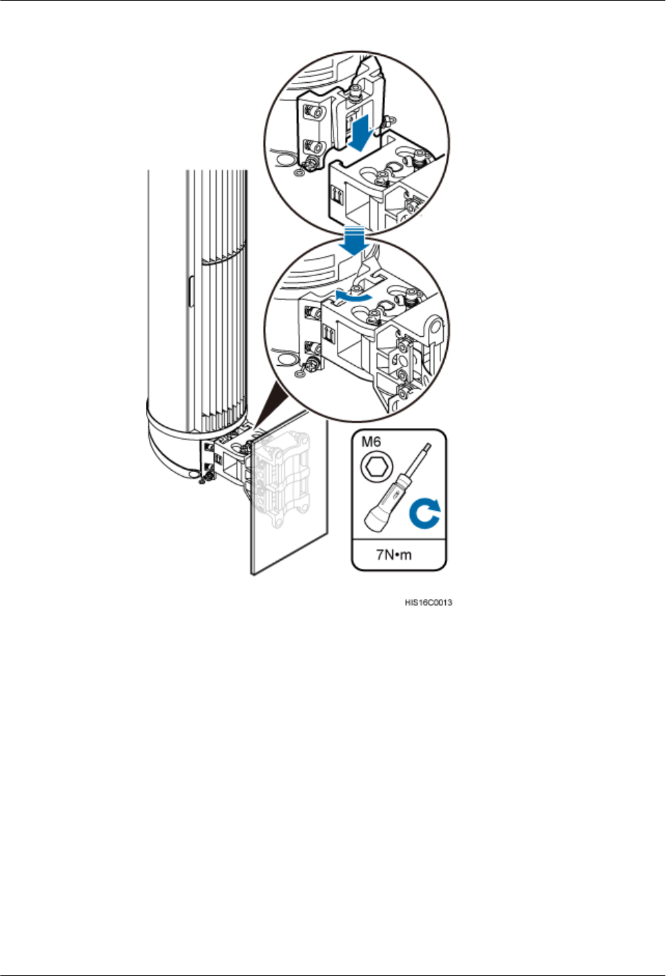
Figure 4-5 Securing the AAU
lIn the pole top installation scenario:
1. Hold the AAU tightly with both hands and insert it into the mounting bracket on the
pole top, and use four M6 hexagon socket-head cap bolts to secure the AAU to 7 N·m
(61.95 lbf·in.), as shown in the following figure.
2. Install the landscaping cover.
AAU3940
Hardware Maintenance Guide 4 Replacing an AAU
Issue 01 (2015-01-15) Huawei Proprietary and Confidential
Copyright © Huawei Technologies Co., Ltd.
13
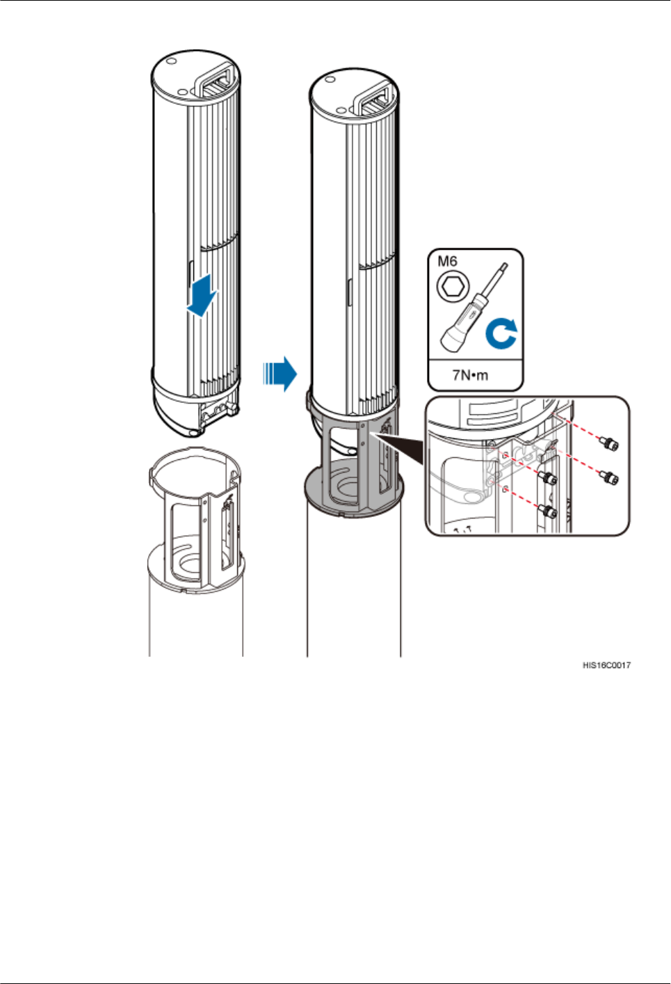
Figure 4-6 Installing an AAU on a pole top
Step 7 Install AAU cables.
1. Open the cover for the maintenance cavity of the AAU.
2. Reconnect cables to the AAU according to the previous record, and ensure that waterproof
blocks are inserted into vacant ports.
3. Close the cover for the maintenance cavity of the AAU.
Step 8 Set the corresponding circuit breaker on the power equipment for the AAU to ON.
AAU3940
Hardware Maintenance Guide 4 Replacing an AAU
Issue 01 (2015-01-15) Huawei Proprietary and Confidential
Copyright © Huawei Technologies Co., Ltd.
14

NOTE
The status of indicators on an AAU that works normally is as follows:
lRUN indicator: blinking
lALM indicator: steady off
lACT indicator: steady on
For details about indicators, see section "Ports and Indicators" in AAU3940 Hardware Description.
Step 9 Take off the ESD wrist strap or ESD gloves, and pack up all tools.
Step 10 Inform the remote engineer that the AAU has been replaced.
----End
Follow-up Procedure
lPlace the replaced component into an ESD box or bag. Then, place the ESD box or bag
into a foam-padded carton or the packing box of the new module.
lComplete the fault form with detailed information about the replaced component.
lContact the local Huawei office to handle the faulty component.
AAU3940
Hardware Maintenance Guide 4 Replacing an AAU
Issue 01 (2015-01-15) Huawei Proprietary and Confidential
Copyright © Huawei Technologies Co., Ltd.
15
5 Replacing the Optical Module
You must disconnect the fiber optic cable from an optical module before replacing the optical
module. Disconnecting the fiber optic cable interrupts transmission of CPRI signals.
Prerequisites
lTo confirm the type of a faulty module, perform the following steps:
–Run the DSP BTSOPTMODULE command on the BSC LMT.
–Run the DSP OPTMODULE command on the NodeB LMT.
–Run the DSP SFP command on the eNodeB LMT.
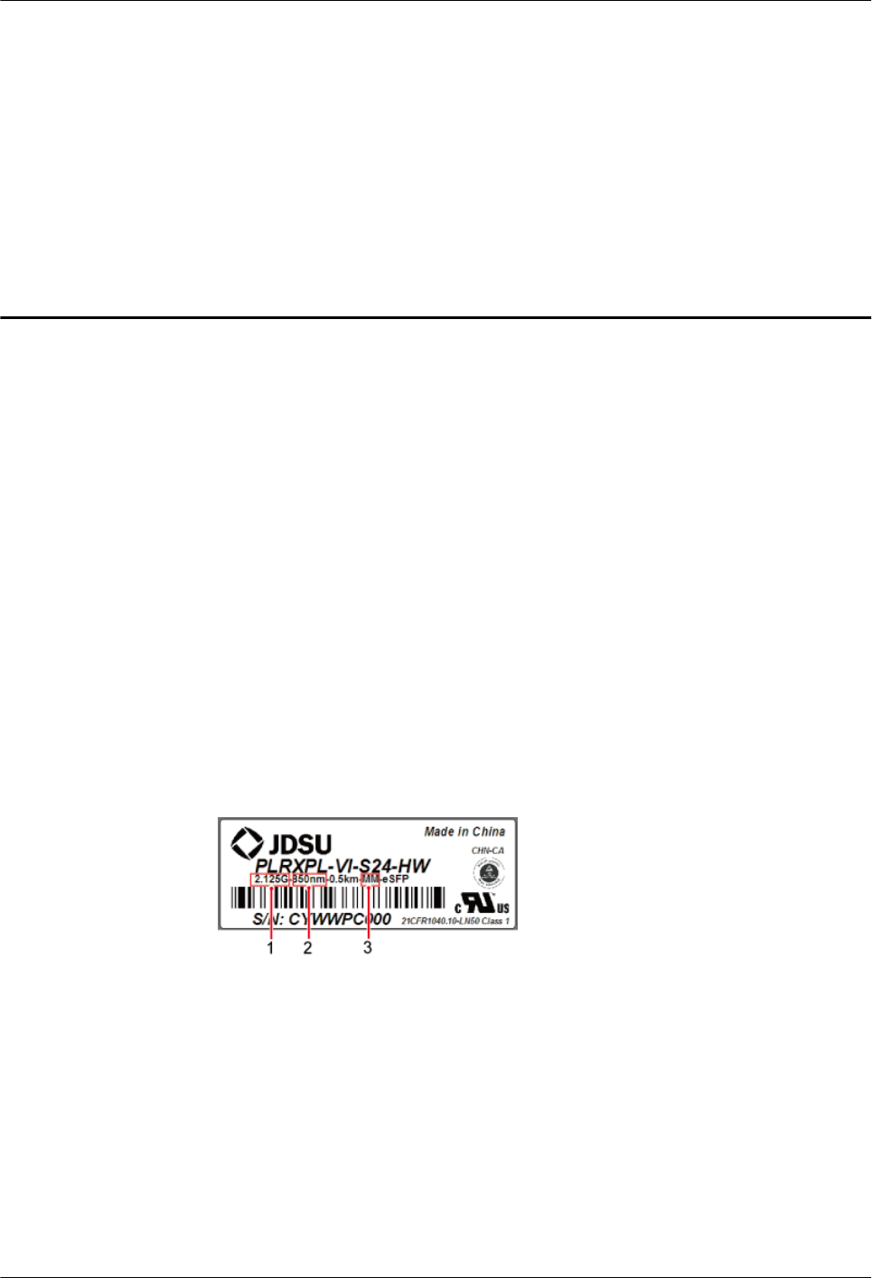
–Identify the type of the faulty module according to the values of Rate, Wavelength,
and Transmission mode in the output information of the command, and obtain a new
optical module of the same type as the faulty one. The type of a new optical module is
identified by the label on the new module. The following figure shows the label on an
optical module.
Figure 5-1 Label on an optical module
(1) Maximum rate (2) Wavelength (3) Transmission mode
lThe type and number of optical modules to be replaced are confirmed, and new optical
modules are ready.
lRequired tools and materials are available, including an ESD box or bag, and ESD gloves.
Context
lOptical modules are inserted into the RX TX CPRI0 and RX TX CPRI1 ports on an AAU.
AAU3940
Hardware Maintenance Guide 5 Replacing the Optical Module
Issue 01 (2015-01-15) Huawei Proprietary and Confidential
Copyright © Huawei Technologies Co., Ltd.
16
lOptical modules are hot-swappable.
lIt takes about five minutes to replace an optical module on the AAU, which involves
disconnecting the fiber optic cable, removing the faulty optical module, inserting a new
optical module, reconnecting the fiber optic cable, and waiting for CPRI links to restore.
Procedure
Step 1 Put on an ESD wrist strap or a pair of ESD gloves.
NOTICE
Take proper ESD protection measures, for example, put on an ESD wrist strap or a pair of ESD
gloves, to prevent electrostatic damage to the boards, modules, or other electronic components.
Step 2 Record the connections of the optical module and fiber optic cable.
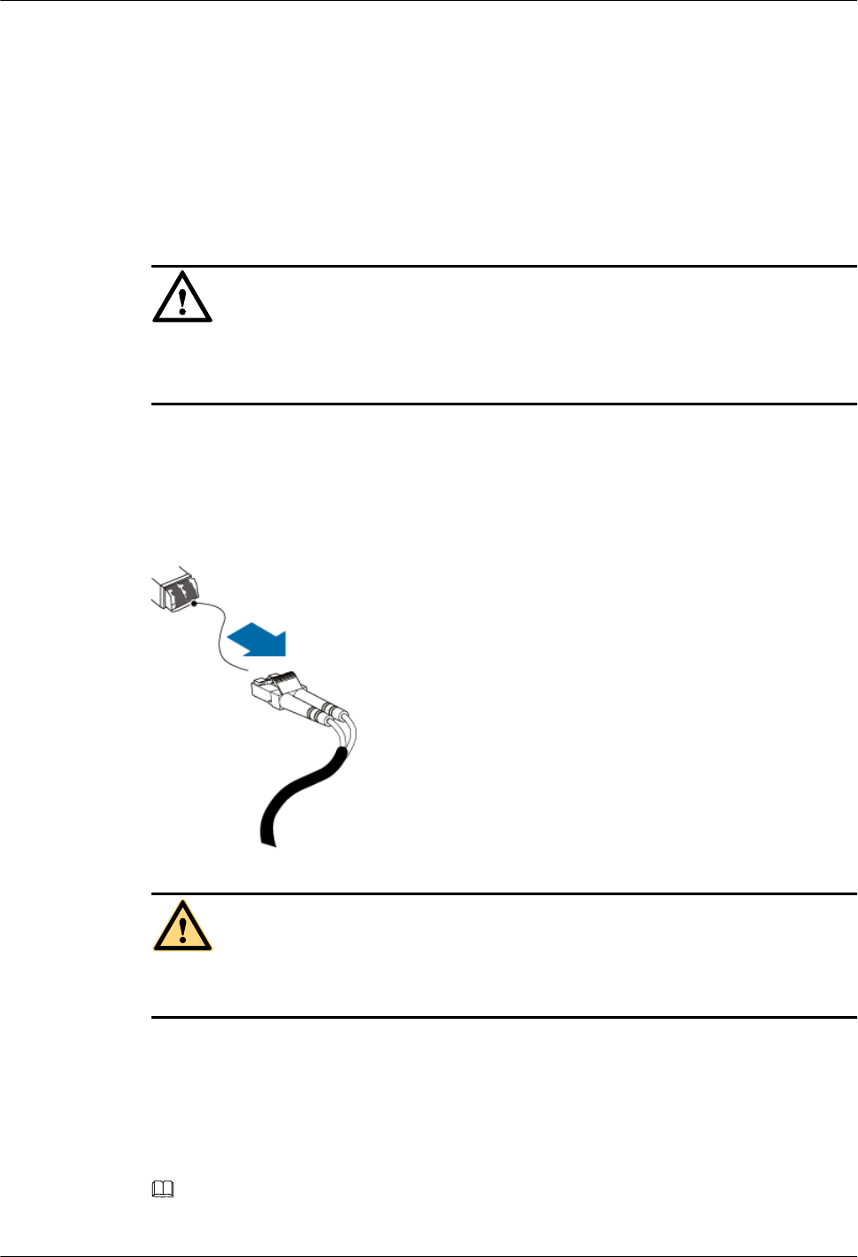
Step 3 Press the latch on the optical connector, and then remove the connector from the faulty optical
module, as shown in the following figure.
Figure 5-2 Removing the cables
CAUTION
Do not look into the optical module without eye protection after removing the fiber optic cable
from the optical module.
Step 4 Lower the puller on the faulty optical module, and then pull the puller until the optical module
is removed from the AAU.
Step 5 Install a new optical module into the AAU according to the label on the module.
NOTE
The optical modules to be installed must match CPRI rates.
AAU3940
Hardware Maintenance Guide 5 Replacing the Optical Module
Issue 01 (2015-01-15) Huawei Proprietary and Confidential
Copyright © Huawei Technologies Co., Ltd.
17

Step 6 Insert the optical connector into the new optical module.
Step 7 Check the transmission of CPRI signals by observing the status of CPRI0 and CPRI1 indicators.
For details about the status of the indicators, see the ports and indicators on an AAU of related
manuals of RRU hardware descriptions.
Step 8 Take off the ESD wrist strap or ESD gloves, and pack up all tools.
----End
Follow-up Procedure
lPlace the replaced component into an ESD box or bag. Then, place the ESD box or bag
into a foam-padded carton or the packing box of the new module.
lComplete the fault form with detailed information about the replaced component.
lContact the local Huawei office to handle the faulty component.
AAU3940
Hardware Maintenance Guide 5 Replacing the Optical Module
Issue 01 (2015-01-15) Huawei Proprietary and Confidential
Copyright © Huawei Technologies Co., Ltd.
18