Huawei Technologies AAU3940 Active Antenna Unit User Manual Installation Guide
Huawei Technologies Co.,Ltd Active Antenna Unit Installation Guide
Contents
- 1. HardwareMaintenanceGuide.pdf
- 2. InstallationGuide.pdf
- 3. UserManual_safety.pdf
InstallationGuide.pdf
AAU3940
Installation Guide
Issue 01
Date 2015-01-15
HUAWEI TECHNOLOGIES CO., LTD.

Copyright © Huawei Technologies Co., Ltd. 2015. All rights reserved.
No part of this document may be reproduced or transmitted in any form or by any means without prior written
consent of Huawei Technologies Co., Ltd.
Trademarks and Permissions
and other Huawei trademarks are trademarks of Huawei Technologies Co., Ltd.
All other trademarks and trade names mentioned in this document are the property of their respective holders.
Notice
The purchased products, services and features are stipulated by the contract made between Huawei and the
customer. All or part of the products, services and features described in this document may not be within the
purchase scope or the usage scope. Unless otherwise specified in the contract, all statements, information,
and recommendations in this document are provided "AS IS" without warranties, guarantees or representations
of any kind, either express or implied.
The information in this document is subject to change without notice. Every effort has been made in the
preparation of this document to ensure accuracy of the contents, but all statements, information, and
recommendations in this document do not constitute a warranty of any kind, express or implied.
Huawei Technologies Co., Ltd.
Address: Huawei Industrial Base
Bantian, Longgang
Shenzhen 518129
People's Republic of China
Website: http://www.huawei.com
Email: support@huawei.com
Issue 01 (2015-01-15) Huawei Proprietary and Confidential
Copyright © Huawei Technologies Co., Ltd.
i
About This Document
Overview
This document describes procedures for installing an active antenna unit 3940 (AAU3940, which
is shortened to AAU in this document) and its cables. It also provides the checklists for hardware
installation.
Product Version
The following table lists the product versions related to this document.
Product Name Solution Version Product Version
DBS3900 lSRAN9.0 and later
lRAN16.0 and later
leRAN7.0 and later
V100R009C00 and later
Intended Audience
lSystem engineers
lInstallation personnel
lMaintenance engineers
Organization
1 Changes in AAU3940 Installation Guide
This section describes changes in AAU3940 Installation Guide.
2 Overview
Before installing an AAU, you must be familiar with its installation options and installation
clearance requirements.
3 Installation Preparations
AAU3940
Installation Guide About This Document
Issue 01 (2015-01-15) Huawei Proprietary and Confidential
Copyright © Huawei Technologies Co., Ltd.
ii

This chapter lists the tools and instruments that must be obtained before the installation. It also
specifies the skills that the onsite personnel must have.
4 Unpacking Check
Unpack and check the delivered equipment to ensure that all materials are included and intact.
5 Installation Process
This chapter describes the process of installing an AAU.
6 (Optional) Installing an ODM
This section describes the procedure and precautions for installing an ODM.
7 Preprocessing the AAU Maintenance Cavity
Before installing an AAU, take power terminals out of its maintenance cavity and install optical
modules.
8 Lifting an AAU
Before installing an AAU on a pole, you need to lift the AAU to the installation position on the
pole.
9 Installing an AAU
This chapter describes the procedures for installing an AAU in different scenarios.
10 Installing AAU Cables
This section describes the procedure and precautions for installing AAU cables.
11 Closing a Maintenance Cavity
After all installation procedures are complete, you need to close the AAU maintenance cavity.
12 (Optional) Installing a Cord Cover for an ODM
This section describes a procedure for installing a cord cover for an ODM after all cables are
installed.
13 Adjusting the Horizontal Azimuth of an Antenna
This section describes the procedure for adjusting the horizontal azimuth of an antenna based
on coverage requirements after all cables are installed.
14 Installation Checklist
This section describes the checklist for AAU hardware installation.
15 Powering on an AAU
This section describes the procedure and precautions for powering on an AAU.
16 Appendix
This chapter describes auxiliary operations during an AAU installation process.
Conventions
Symbol Conventions
AAU3940
Installation Guide About This Document
Issue 01 (2015-01-15) Huawei Proprietary and Confidential
Copyright © Huawei Technologies Co., Ltd.
iii
The symbols that may be found in this document are defined as follows.
Symbol Description
Indicates an imminently hazardous situation which, if not
avoided, will result in death or serious injury.
Indicates a potentially hazardous situation which, if not
avoided, could result in death or serious injury.
Indicates a potentially hazardous situation which, if not
avoided, may result in minor or moderate injury.
Indicates a potentially hazardous situation which, if not
avoided, could result in equipment damage, data loss,
performance deterioration, or unanticipated results.
NOTICE is used to address practices not related to personal
injury.
Calls attention to important information, best practices and
tips.
NOTE is used to address information not related to personal
injury, equipment damage, and environment deterioration.
General Conventions
The general conventions that may be found in this document are defined as follows.
Convention Description
Times New Roman Normal paragraphs are in Times New Roman.
Boldface Names of files, directories, folders, and users are in
boldface. For example, log in as user root.
Italic Book titles are in italics.
Courier New Examples of information displayed on the screen are in
Courier New.
Command Conventions
The command conventions that may be found in this document are defined as follows.
Convention Description
Boldface The keywords of a command line are in boldface.
AAU3940
Installation Guide About This Document
Issue 01 (2015-01-15) Huawei Proprietary and Confidential
Copyright © Huawei Technologies Co., Ltd.
iv
Convention Description
Italic Command arguments are in italics.
[ ] Items (keywords or arguments) in brackets [ ] are optional.
{ x | y | ... } Optional items are grouped in braces and separated by
vertical bars. One item is selected.
[ x | y | ... ] Optional items are grouped in brackets and separated by
vertical bars. One item is selected or no item is selected.
{ x | y | ... }*Optional items are grouped in braces and separated by
vertical bars. A minimum of one item or a maximum of all
items can be selected.
[ x | y | ... ]*Optional items are grouped in brackets and separated by
vertical bars. Several items or no item can be selected.
GUI Conventions
The GUI conventions that may be found in this document are defined as follows.
Convention Description
Boldface Buttons, menus, parameters, tabs, window, and dialog titles
are in boldface. For example, click OK.
>Multi-level menus are in boldface and separated by the ">"
signs. For example, choose File > Create > Folder.
Keyboard Operations
The keyboard operations that may be found in this document are defined as follows.
Format Description
Key Press the key. For example, press Enter and press Tab.
Key 1+Key 2 Press the keys concurrently. For example, pressing Ctrl+Alt
+A means the three keys should be pressed concurrently.
Key 1, Key 2 Press the keys in turn. For example, pressing Alt, A means
the two keys should be pressed in turn.
Mouse Operations
The mouse operations that may be found in this document are defined as follows.
AAU3940
Installation Guide About This Document
Issue 01 (2015-01-15) Huawei Proprietary and Confidential
Copyright © Huawei Technologies Co., Ltd.
v

Action Description
Click Select and release the primary mouse button without moving
the pointer.
Double-click Press the primary mouse button twice continuously and
quickly without moving the pointer.
Drag Press and hold the primary mouse button and move the
pointer to a certain position.
AAU3940
Installation Guide About This Document
Issue 01 (2015-01-15) Huawei Proprietary and Confidential
Copyright © Huawei Technologies Co., Ltd.
vi

Contents
About This Document.....................................................................................................................ii
1 Changes in AAU3940 Installation Guide..................................................................................1
2 Overview.........................................................................................................................................2
2.1 Installation Scenario.......................................................................................................................................................3
2.2 Installation Clearance Requirements..............................................................................................................................9
2.3 AAU Mounting Kits.....................................................................................................................................................11
2.4 ODM Description.........................................................................................................................................................12
2.5 Surge Protection Requirements....................................................................................................................................15
3 Installation Preparations............................................................................................................17
3.1 Documents....................................................................................................................................................................18
3.2 Tools and Instruments..................................................................................................................................................18
3.3 Requirements for Onsite Personnel..............................................................................................................................19
4 Unpacking Check........................................................................................................................21
5 Installation Process.....................................................................................................................23
6 (Optional) Installing an ODM..................................................................................................25
7 Preprocessing the AAU Maintenance Cavity.........................................................................30
8 Lifting an AAU.............................................................................................................................34
9 Installing an AAU........................................................................................................................37
9.1 Installing an AAU on a Pole.........................................................................................................................................38
9.2 Installing an AAU on the Top of a Pole.......................................................................................................................44
9.3 Installing an AAU on a Wall........................................................................................................................................48
10 Installing AAU Cables..............................................................................................................55
10.1 Cabling Requirements................................................................................................................................................56
10.2 Installing an AAU PGND Cable................................................................................................................................62
10.3 Installing an AAU Power Cable.................................................................................................................................67
10.4 Installing an ODM Power Cable................................................................................................................................72
10.5 Installing a Trunk CPRI Fiber Optic Cable Between an ODM and a BBU...............................................................73
10.6 Installing a CPRI Fiber Optic Cable Between an AAU and a BBU or Between an AAU and an ODM...................80
AAU3940
Installation Guide Contents
Issue 01 (2015-01-15) Huawei Proprietary and Confidential
Copyright © Huawei Technologies Co., Ltd.
vii

11 Closing a Maintenance Cavity................................................................................................86
12 (Optional) Installing a Cord Cover for an ODM.................................................................87
13 Adjusting the Horizontal Azimuth of an Antenna.............................................................89
14 Installation Checklist................................................................................................................93
15 Powering on an AAU................................................................................................................95
16 Appendix.....................................................................................................................................97
16.1 Assembling the OT Terminal and the Power Cable...................................................................................................98
16.2 Adding a Tool-Less Female Connector (Pressfit Type) to an AAU Power Cable on the AAU Side......................102
AAU3940
Installation Guide Contents
Issue 01 (2015-01-15) Huawei Proprietary and Confidential
Copyright © Huawei Technologies Co., Ltd.
viii
1 Changes in AAU3940 Installation Guide
This section describes changes in AAU3940 Installation Guide.
01 (2015-01-15)
This is the first commercial release.
Compared with issue Draft A (2014-10-30), no information is added to or deleted from this issue.
Compared with issue Draft A (2014-10-30), this issue includes the following changes.
Topic Change Description
Entire document Some figure updates caused by the structure
modification of the AAU.
Draft A (2014-10-30)
This is a draft.
AAU3940
Installation Guide 1 Changes in AAU3940 Installation Guide
Issue 01 (2015-01-15) Huawei Proprietary and Confidential
Copyright © Huawei Technologies Co., Ltd.
1

2 Overview
About This Chapter
Before installing an AAU, you must be familiar with its installation options and installation
clearance requirements.
2.1 Installation Scenario
An AAU can be installed independently or can be installed together with an ODM04A (ODM
for short) on a pole, a wall, or the top of a pole.
2.2 Installation Clearance Requirements
This section describes installation clearance requirements in different scenarios.
2.3 AAU Mounting Kits
This section describes mounting kits for installing AAUs on a pole, a wall, and the top of a pole.
2.4 ODM Description
This section describes functions and specifications of an ODM.
2.5 Surge Protection Requirements
When an AAU is installed on a pole or the top of a pole, the AAU must meet the surge protection
requirements. Otherwise, surge protection measures must be taken.
AAU3940
Installation Guide 2 Overview
Issue 01 (2015-01-15) Huawei Proprietary and Confidential
Copyright © Huawei Technologies Co., Ltd.
2

2.1 Installation Scenario
An AAU can be installed independently or can be installed together with an ODM04A (ODM
for short) on a pole, a wall, or the top of a pole.
Installation Scenario Description
NOTE
An AAU has been camouflaged and the second camouflaging is not allowed in principle. If the second
camouflaging must be performed, you need to contact Huawei technical engineers for assessment.
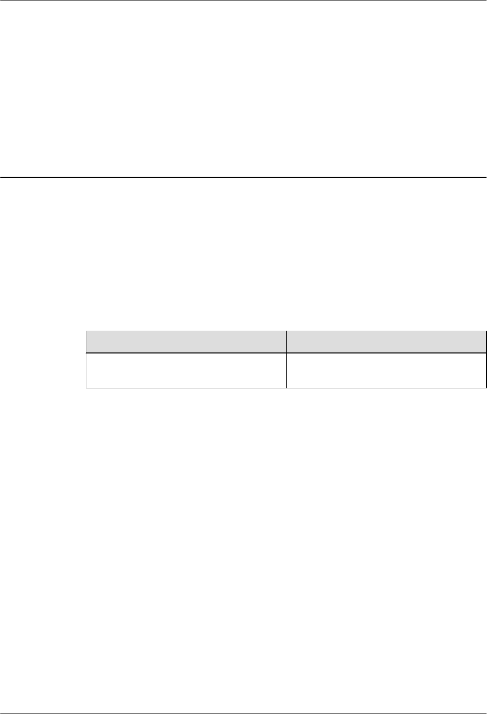
The following figure shows scenarios in which AAUs are installed independently.
AAU3940
Installation Guide 2 Overview
Issue 01 (2015-01-15) Huawei Proprietary and Confidential
Copyright © Huawei Technologies Co., Ltd.
3
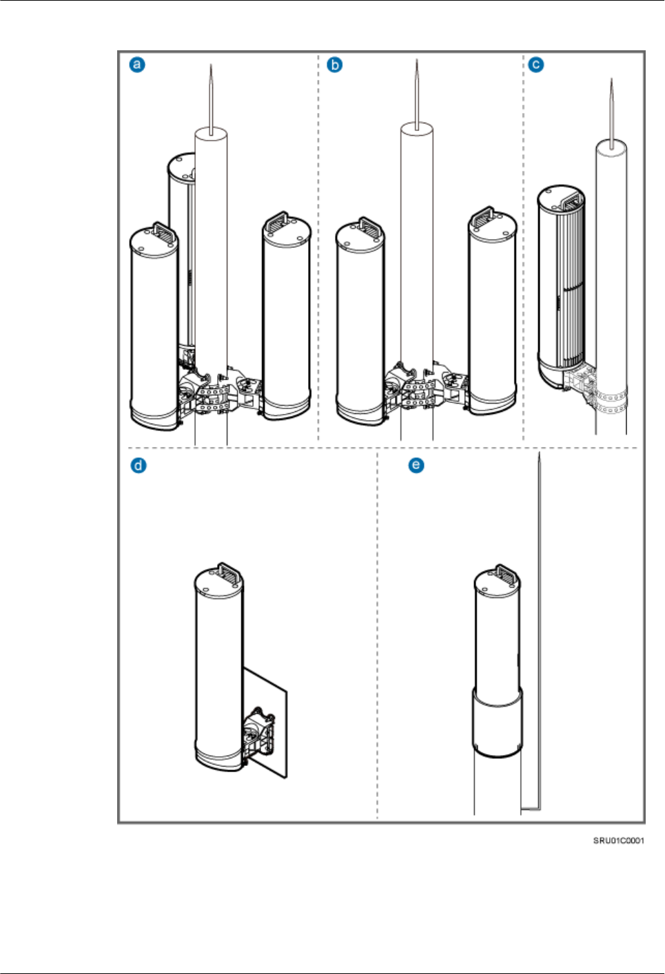
Figure 2-1 Scenario in which AAUs are installed independently
a: Scenario in which three AAUs are
installed on a pole
b: Scenario in which two AAUs are
installed on a pole
c: Scenario in which one AAU is
installed on a pole
d: Scenario in which an AAU is
installed on a wall
e: Scenario in which an AAU is
installed on the top of a pole
-
AAU3940
Installation Guide 2 Overview
Issue 01 (2015-01-15) Huawei Proprietary and Confidential
Copyright © Huawei Technologies Co., Ltd.
4

The following figure shows scenarios in which AAUs are installed together with ODMs.
NOTE
AAUs can also be installed together with optical distribution frames (ODFs). This document uses ODMs as
examples.
AAU3940
Installation Guide 2 Overview
Issue 01 (2015-01-15) Huawei Proprietary and Confidential
Copyright © Huawei Technologies Co., Ltd.
5
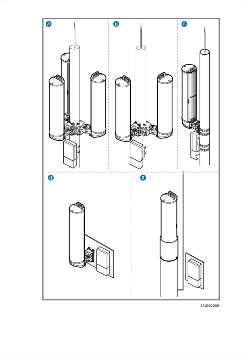
Figure 2-2 Scenarios in which AAUs are installed together with ODMs
a: Scenario in which three AAUs are
installed together with an ODM on a
pole
b: Scenario in which two AAUs are
installed together with an ODM on a
pole
c: Scenario in which an AAU is
installed together with an ODM on a
pole
AAU3940
Installation Guide 2 Overview
Issue 01 (2015-01-15) Huawei Proprietary and Confidential
Copyright © Huawei Technologies Co., Ltd.
6
d: Scenario in which an AAU is
installed together with an ODM on a
wall
e: Scenario in which an AAU is
installed on the top of a pole and an
ODM is installed on a wall
-
NOTICE
In all scenarios, AAUs are installed together with their bottoms facing downwards. The vertical
deviation angle of a support must be less than or equal to 5 degrees, as shown in the following
figure.
Figure 2-3 Vertical deviation angle of an AAU
(1) AAU (2) Support (pole, top of a pole, or wall)
Requirements of Installation Scenarios
The following table describes the requirements for poles, walls, and tops of poles in the preceding
installation scenarios.
AAU3940
Installation Guide 2 Overview
Issue 01 (2015-01-15) Huawei Proprietary and Confidential
Copyright © Huawei Technologies Co., Ltd.
7

Table 2-1 Requirements of installation scenarios
Installation
Scenario
Requirements
One AAU is installed
on a pole.
lThe part of a pole for installing an AAU should have a diameter
of 60 mm to 300 mm (2.36 in. to 11.81 in.) and the recommended
wall thickness of a pole is greater than or equal to 4 mm (0.16 in.).
lIf the part of a pole for installing an AAU has a diameter greater
than 300 mm (11.81 in.), an auxiliary pole is required for installing
the AAU.
Two AAUs are
installed on a pole.
lTwo AAUs are installed back to back in most cases.
lThe recommended wall thickness of a pole is greater than or equal
to 4 mm (0.16 in.).
lWhen AAUs are installed on the same level, the part of a pole for
installing the AAUs should have a diameter of 80 mm to 230 mm
(3.15 in. to 9.06 in.). When AAUs are installed on different levels,
the parts of a pole for installing the AAUs should have a diameter
of 60 mm to 230 mm (2.36 in. to 9.06 in.).
lIf the part of a pole for installing AAUs has a diameter greater than
230 mm (9.06 in.), an auxiliary pole is required for installing the
AAUs.
Three AAUs are
installed on a pole.
lThe recommended wall thickness of a pole is greater than or equal
to 4 mm (0.16 in.).
lWhen AAUs are installed on the same level, the part of a pole for
installing the AAUs should have a diameter of 80 mm to 230 mm
(3.15 in. to 9.06 in.). When AAUs are installed on different levels,
the parts of a pole for installing the AAUs should have a diameter
of 60 mm to 230 mm (2.36 in. to 9.06 in.).
lIf the part of a pole for installing AAUs has a diameter greater than
230 mm (9.06 in.), an auxiliary pole is required for installing the
AAUs.
AAUs are installed
on a wall.
A wall should have a load-bearing capacity of 80 kg (176.37 lb).
An AAU is installed
on the top of a pole.
lThe recommended wall thickness of a pole is greater than or equal
to 4 mm (0.16 in.).
lA flange plate must be installed on the top of a pole for attaching
an AAU to the pole.
lThe recommended thickness of a flange plate is greater than or
equal to 6 mm (0.24 in.).
lTo achieve neat installation, it is recommended that the diameter
of a pole be the same as that of a flange plate.
AAU3940
Installation Guide 2 Overview
Issue 01 (2015-01-15) Huawei Proprietary and Confidential
Copyright © Huawei Technologies Co., Ltd.
8
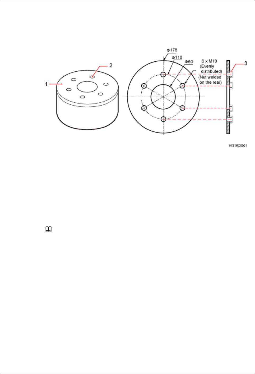
The method of connecting a flange plate to the top of a pole is determined by customers. The
following figure shows the design specifications of ports on a flange plate for connecting an
AAU.
Figure 2-4 Design specifications of ports on a flange plate
(1) Flange plate (2) Screw hole (3) Nut
2.2 Installation Clearance Requirements
This section describes installation clearance requirements in different scenarios.
The following figure shows the clearance requirements for installing an AAU.
NOTE
The following figure shows the clearance requirements for independently installing an AAU. When an AAU is
installed together with an ODM, the clearance requirements are different.
AAU3940
Installation Guide 2 Overview
Issue 01 (2015-01-15) Huawei Proprietary and Confidential
Copyright © Huawei Technologies Co., Ltd.
9
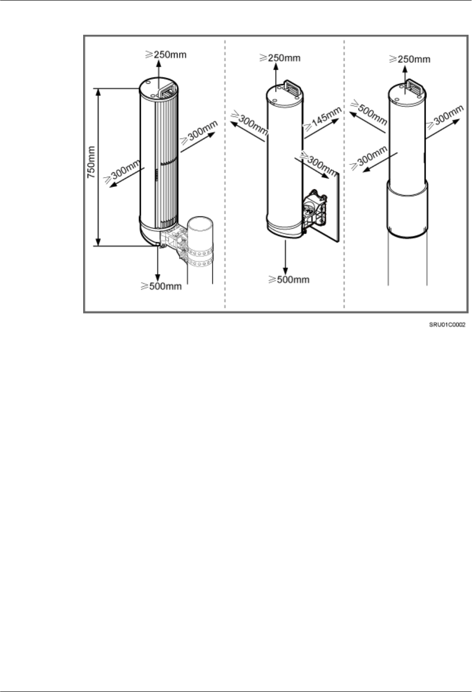
Figure 2-5 AAU installation clearance requirements
The following figure shows the clearance requirements for installing an ODM.
AAU3940
Installation Guide 2 Overview
Issue 01 (2015-01-15) Huawei Proprietary and Confidential
Copyright © Huawei Technologies Co., Ltd.
10
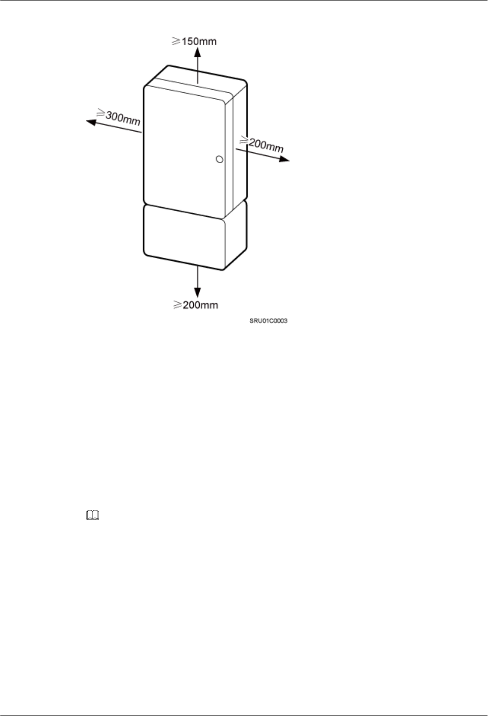
Figure 2-6 ODM installation clearance requirements
2.3 AAU Mounting Kits
This section describes mounting kits for installing AAUs on a pole, a wall, and the top of a pole.
Mounting Kits for an AAU Installed on a Pole or Wall
The same mounting kits are used for installing an AAU on a pole and installing an AAU on a
wall. However, the procedure for installing an AAU on a pole is different from that for installing
an AAU on a wall. The following figure shows the mounting kits for an AAU.
NOTE
When an AAU is installed on a pole or wall, the main bracket and attachment plate are required.
lWhen an AAU is installed on a pole, M8x80 expansion anchor bolts are not required.
lWhen an AAU is installed on a wall, steel belts are not required. Therefore, you need to remove the steel
belts from mounting kits.
AAU3940
Installation Guide 2 Overview
Issue 01 (2015-01-15) Huawei Proprietary and Confidential
Copyright © Huawei Technologies Co., Ltd.
11
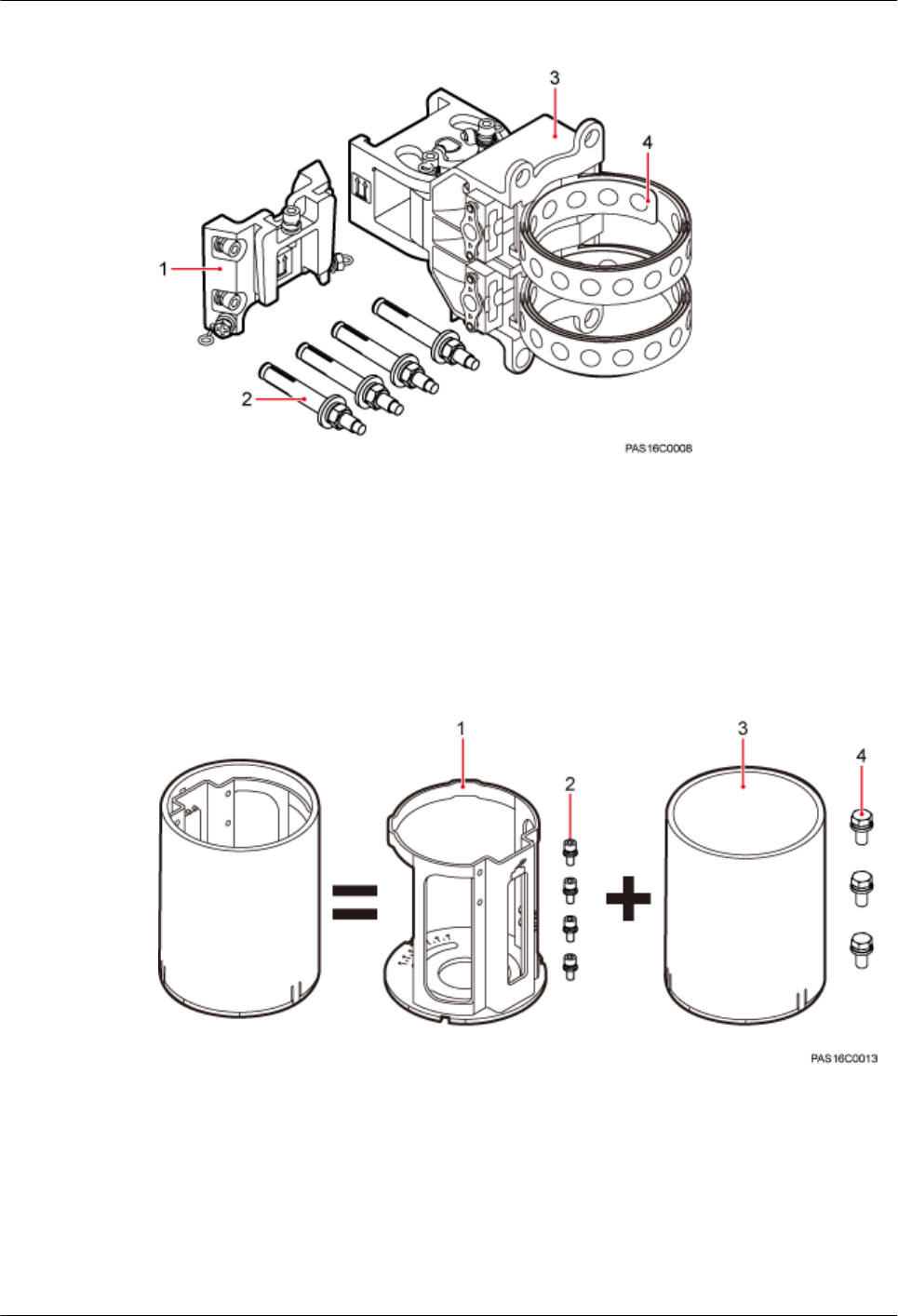
Figure 2-7 Mounting kits for an AAU installed on a pole or wall
(1) Attachment plate (2) M8x80 expansion anchor bolt (3) Main mounting bracket (4) Steel belt
Mounting Kits for an AAU Installed on the Top of a Pole
Mounting kits for installing an AAU on the top of a pole include a support and a landscaping
cover, as shown in the following figure.
Figure 2-8 Mounting kits installing for an AAU on the top of a pole
(1) Support (2) M6x16 bolt (3) Landscaping cover (4) M10x30 bolt
2.4 ODM Description
This section describes functions and specifications of an ODM.
AAU3940
Installation Guide 2 Overview
Issue 01 (2015-01-15) Huawei Proprietary and Confidential
Copyright © Huawei Technologies Co., Ltd.
12
Function
The ODM is an auxiliary low-power AC device for providing power distribution and fiber
distribution. The ODM cover provides fiber distribution and the ODM provides power
distribution. The following figure shows the structure of an ODM.
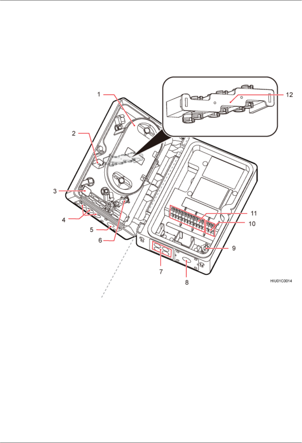
Figure 2-9 ODM structure
(1) Splicing tray (2) Fiber holder (3) Clip (4) Holes for output fiber
optic cables
(5) Hole for the input fiber
optic cable
(6) Hanger for the trunk
fiber optic cable
(7) Cable holes for the
output power cables
(8) Cable hole for the
input power cable
(9) Screwdriver (10) Terminal block for
input power cables
(11) Terminal block for
output power cables
(12) Pigtail adapter
Specification
The following table describes the specifications of an ODM.
AAU3940
Installation Guide 2 Overview
Issue 01 (2015-01-15) Huawei Proprietary and Confidential
Copyright © Huawei Technologies Co., Ltd.
13
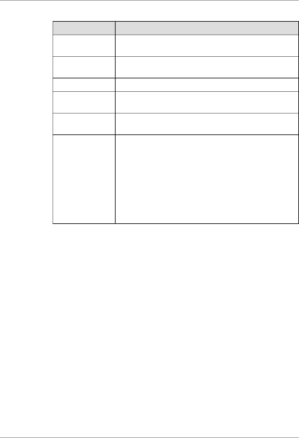
Table 2-2 ODM specifications
Item Specifications
Dimensions (H x W x
D)
232 mm x 158 mm x 96.5 mm (9.13 in. x 6.22 in. x 3.80 in.)
Upper-level circuit
breaker
20 A
Support power 1650 W
Power supply
capacity
One AC power input and four AC power outputs (Each power output
is less than or equal to 400 W.)
Fiber division
capacity
One trunk fiber optic cable and three pairs of breakout fiber optic
cables (six breakout fiber optic cables)
Cable specifications lCross-sectional area of an input power cable: 1.5 mm2 to 4 mm2
(0.002 in.2 to 0.006 in.2). External diameter of an input power
cable: 8.3 mm to 15mm (0.33 in. to 0.59 in.)
lCross-sectional area of an output power cable: 1.5 mm2 to 2.5
mm2 (0.002 in.2 to 0.004 in.2). External diameter of an output
power cable: 8.3 mm to 13.5 mm (0.33 in. to 0.53 in.)
lExternal diameter of an input fiber optic cable: 9.8 mm to 11 mm
(0.39 in. to 0.43 in.)
lExternal diameter of an output fiber optic cable: 7.0 mm (0.28 in.)
Mounting Kits
The following figure shows the mounting kits for an ODM.
AAU3940
Installation Guide 2 Overview
Issue 01 (2015-01-15) Huawei Proprietary and Confidential
Copyright © Huawei Technologies Co., Ltd.
14
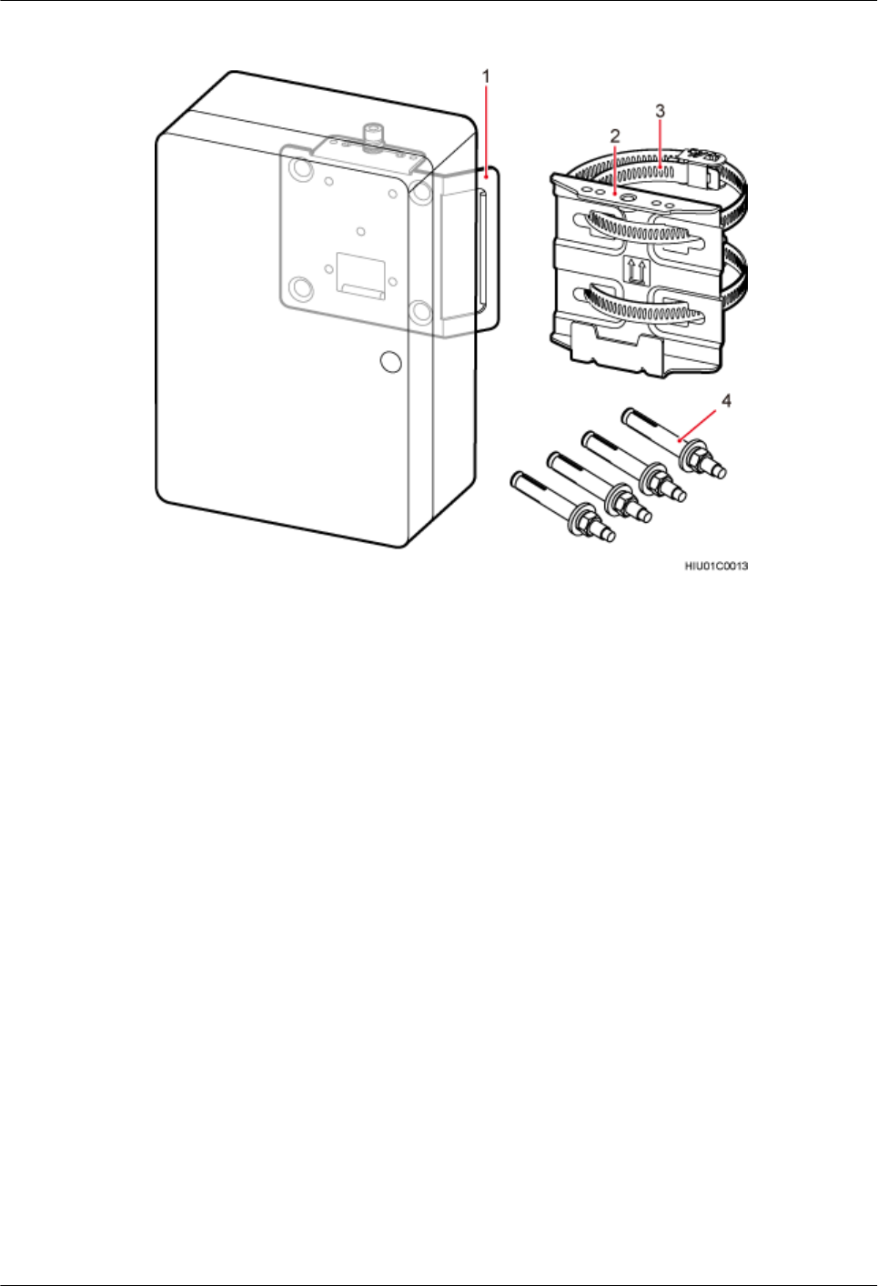
Figure 2-10 Mounting kits for an ODM
(1) Attachment plate (2) Mounting bracket (3) Steel belt (4) Expansion bolt
2.5 Surge Protection Requirements
When an AAU is installed on a pole or the top of a pole, the AAU must meet the surge protection
requirements. Otherwise, surge protection measures must be taken.
A direct lightning strike protection measure must be taken (that is, a lightning rod is installed)
if AAU installation meets the following conditions:
lWhen the AAU is installed on a pole or the top of a pole, the distance between the top of
the pole and the top of the AAU is less than 30 cm (0.98 ft).
lThe AAU is not installed within the protection range of the lightning rod.
When a lightning rod is installed near the AAU installation position, the following conditions
must be met:
lThe distance between the lightning rod and the top of the AAU must be greater than 30 cm
(0.98 ft).
lThe lightning rod must be properly connected to the onsite ground grid.
lThe AAU PGND cable must be routed along the inner side of the pole and is connected to
the ground bar of the onsite ground grid.
lIn addition to the above conditions, the lightning rod installation must meet other building
surge protection requirements.
AAU3940
Installation Guide 2 Overview
Issue 01 (2015-01-15) Huawei Proprietary and Confidential
Copyright © Huawei Technologies Co., Ltd.
15
The following figure shows AAU installation scenarios in which surge protection measures are
taken.
Figure 2-11 AAU installation scenarios in which surge protection measures are taken
(1) Lightning rods (2) AAUs (3) AAU PGND cables
(4) Ground bars of ground girds (5) PGND cables for metal poles -
AAU3940
Installation Guide 2 Overview
Issue 01 (2015-01-15) Huawei Proprietary and Confidential
Copyright © Huawei Technologies Co., Ltd.
16

3 Installation Preparations
About This Chapter
This chapter lists the tools and instruments that must be obtained before the installation. It also
specifies the skills that the onsite personnel must have.
3.1 Documents
This section lists the documents that must be obtained before the installation.
3.2 Tools and Instruments
You must prepare the following tools and instruments before the installation.
3.3 Requirements for Onsite Personnel
Onsite personnel must be qualified and trained. Before performing any operation, onsite
personnel must be familiar with correct operation methods and safety precautions.
AAU3940
Installation Guide 3 Installation Preparations
Issue 01 (2015-01-15) Huawei Proprietary and Confidential
Copyright © Huawei Technologies Co., Ltd.
17
3.1 Documents
This section lists the documents that must be obtained before the installation.
lBefore the installation, familiarize yourself with related information in the following
documents:
–AAU3940 Hardware Description
–Safety Information
lDuring the installation, refer to the following document:
–Installation Reference
3.2 Tools and Instruments
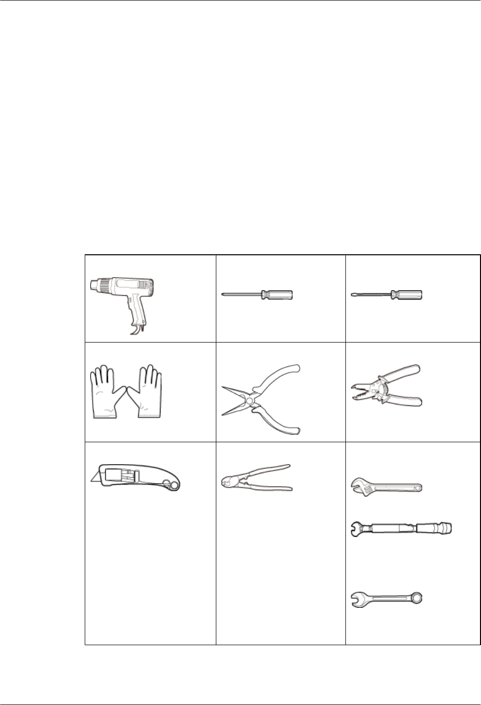
You must prepare the following tools and instruments before the installation.
Heat gun Phillips screwdriver (M3 to
M6)
Flat-head screwdriver (M3 to
M6)
ESD gloves Needle-nose pliers Wire stripper
Utility knife Cable cutter Adjustable wrench (size ≥ 32
mm or 1.26 in.)
Torque wrench
Size: 16 mm (0.63 in.) and 32
mm (1.26 in.)
Combination wrench
Size: 16 mm (0.63 in.) and 32
mm (1.26 in.)
AAU3940
Installation Guide 3 Installation Preparations
Issue 01 (2015-01-15) Huawei Proprietary and Confidential
Copyright © Huawei Technologies Co., Ltd.
18
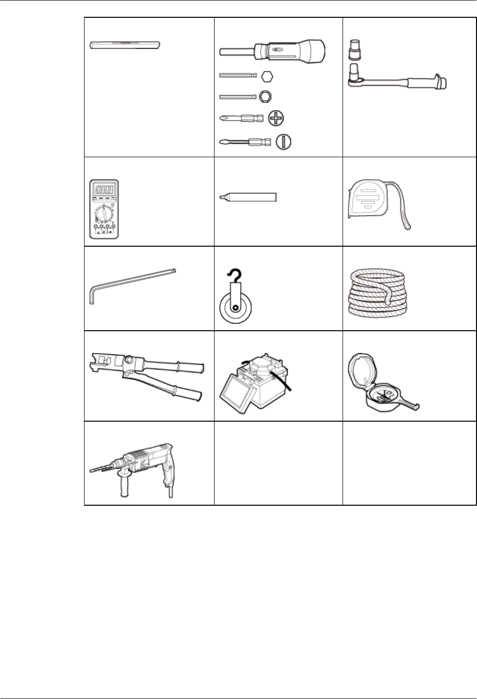
Level Torque screwdriver Torque socket
Multimeter Marker (diameter ≤ 10 mm
or 0.39 in.)
Measuring tape
Hex key Fixed pulley Lifting sling
Hydraulic pliers Fiber fusion splicer Geologic compass
Hammer drill
3.3 Requirements for Onsite Personnel
Onsite personnel must be qualified and trained. Before performing any operation, onsite
personnel must be familiar with correct operation methods and safety precautions.
The customer must pay attention to the following points before the installation:
lThe customer's technical engineers must be trained by Huawei and be familiar with the
installation and operation methods.
AAU3940
Installation Guide 3 Installation Preparations
Issue 01 (2015-01-15) Huawei Proprietary and Confidential
Copyright © Huawei Technologies Co., Ltd.
19

lThe number of onsite personnel depends on the engineering schedule and installation
environment. Generally, four to five onsite personnel are necessary.
AAU3940
Installation Guide 3 Installation Preparations
Issue 01 (2015-01-15) Huawei Proprietary and Confidential
Copyright © Huawei Technologies Co., Ltd.
20
4 Unpacking Check
Unpack and check the delivered equipment to ensure that all materials are included and intact.
Context
NOTE
When transporting, moving, or installing equipment or components,
lPrevent them from colliding with doors, walls, shelves, or other objects.
lAvoid touching their unpainted metal surfaces with sweat-soaked or dirty gloves or bare hands.
NOTICE
Power on an AAU within 24 hours after unpacking it.
Procedure
Step 1 Check the total number of articles in each case according to the packing list.
If... Then...
The total number tallies with the packing
list
Go to 2.
The total number does not tally with the
packing list
Find out the cause and report any missing
articles to the local Huawei office.
Step 2 Check the exterior of the packing case.
If... Then...
The outer packing case is intact Go to Step 3.
AAU3940
Installation Guide 4 Unpacking Check
Issue 01 (2015-01-15) Huawei Proprietary and Confidential
Copyright © Huawei Technologies Co., Ltd.
21
If... Then...
The outer packing is severely damaged or
soaked
Find out the cause and report the situation to
the local Huawei office.
Step 3 Check the type and quantity of the equipment in the cases according to the packing list.
If... Then...
Types and quantity of the articles tally with
those on the packing list
Sign the Packing List with the customer.
There are any goods missing, incorrectly
delivered, or damaged
Report the situation to the local Huawei office.
CAUTION
To protect the equipment and prevent damage to the equipment, you are advised to keep the
unpacked equipment and packing materials indoors, take photos of the stocking environment,
packing case or carton, packing materials, and any rusted or eroded equipment, and then file the
photos.
Step 4 Take the recording form out of the carton containing antennas and fill in the form according to
the actual situation.
NOTICE
Ensure that the RET SN on the antenna's name plate is consistent with that in the recording form.
----End
AAU3940
Installation Guide 4 Unpacking Check
Issue 01 (2015-01-15) Huawei Proprietary and Confidential
Copyright © Huawei Technologies Co., Ltd.
22

5 Installation Process
This chapter describes the process of installing an AAU.
The following figure shows the installation process.
AAU3940
Installation Guide 5 Installation Process
Issue 01 (2015-01-15) Huawei Proprietary and Confidential
Copyright © Huawei Technologies Co., Ltd.
23
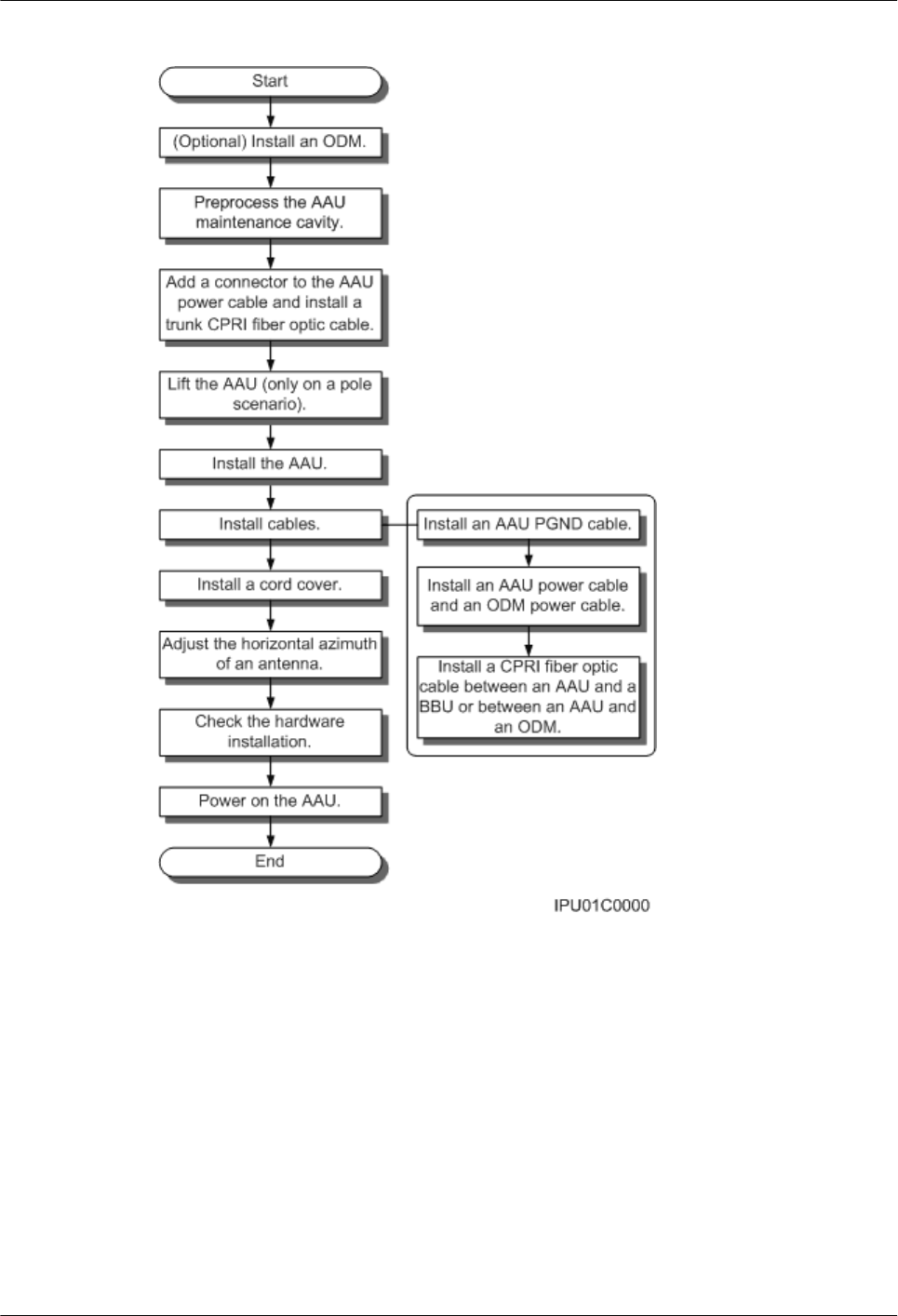
Figure 5-1 Installation process
AAU3940
Installation Guide 5 Installation Process
Issue 01 (2015-01-15) Huawei Proprietary and Confidential
Copyright © Huawei Technologies Co., Ltd.
24
6 (Optional) Installing an ODM
This section describes the procedure and precautions for installing an ODM.
Context
The part of a pole for installing the mounting bracket of an ODM should have a diameter of 114
mm to 380 mm (4.489 in. to 14.96 in.).
Procedure
lInstalling an ODM on a wall
1. Determine a position for installing an ODM on a wall, use a level to adjust the position
to ensure that the mounting bracket will be placed horizontally, and use a marker to
mark anchor points, as shown in the following figure.
Figure 6-1 Determining a position for installing an ODM
(1) Level (2) Screw hole (3) Marker
AAU3940
Installation Guide 6 (Optional) Installing an ODM
Issue 01 (2015-01-15) Huawei Proprietary and Confidential
Copyright © Huawei Technologies Co., Ltd.
25
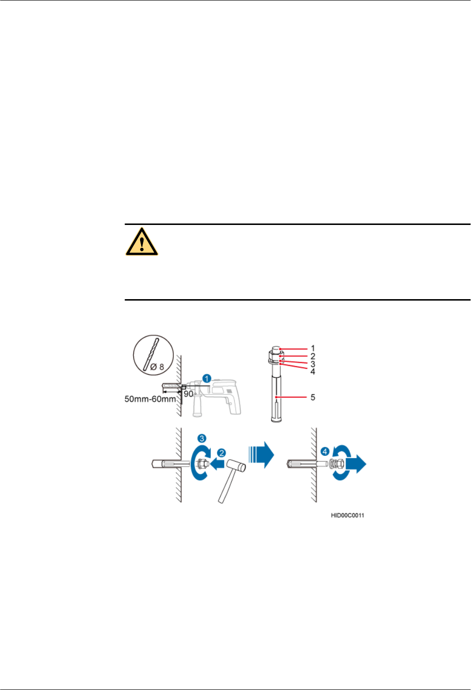
2. Drill holes at the anchor points and install expansion bolts in the holes, as shown in
the following figure.
a. Use a hammer drill with a Φ8 bit to drill holes vertically at the marked anchor
points. Ensure that the depth of each hole ranges from 50 mm to 60 mm (1.97 in.
to 2.36 in.).
b. Use a vacuum cleaner to clear the dust inside and around the holes, and measure
the distances between holes. If any of the holes is beyond the acceptable range,
mark a new anchor point and drill a new hole.
c. Tighten an expansion bolt slightly and place it vertically into each hole.
d. Use a rubber mallet to pound the expansion bolt until it goes into the hole
completely. Ensure that a 20 mm (0.79 in.) part of the expansion bolt is left
outside the wall.
e. Remove the M6x60 bolt, nut, spring washer, and flat washer in sequence.
CAUTION
Take proper safety measures to protect your eyes and respiratory tract against the dust
before drilling holes.
Figure 6-2 Drilling a hole and inserting an expansion bolt assembly
(1) M6x60 bolt (2) Nut (3) Spring washer (4) Flat washer (5) Expansion tube
3. Place the mounting bracket against the installation position on the wall, and use four
M6x60 bolts to tighten the mounting bracket to 5 N·m (44.25 lbf·in.), as shown in the
following figure.
AAU3940
Installation Guide 6 (Optional) Installing an ODM
Issue 01 (2015-01-15) Huawei Proprietary and Confidential
Copyright © Huawei Technologies Co., Ltd.
26
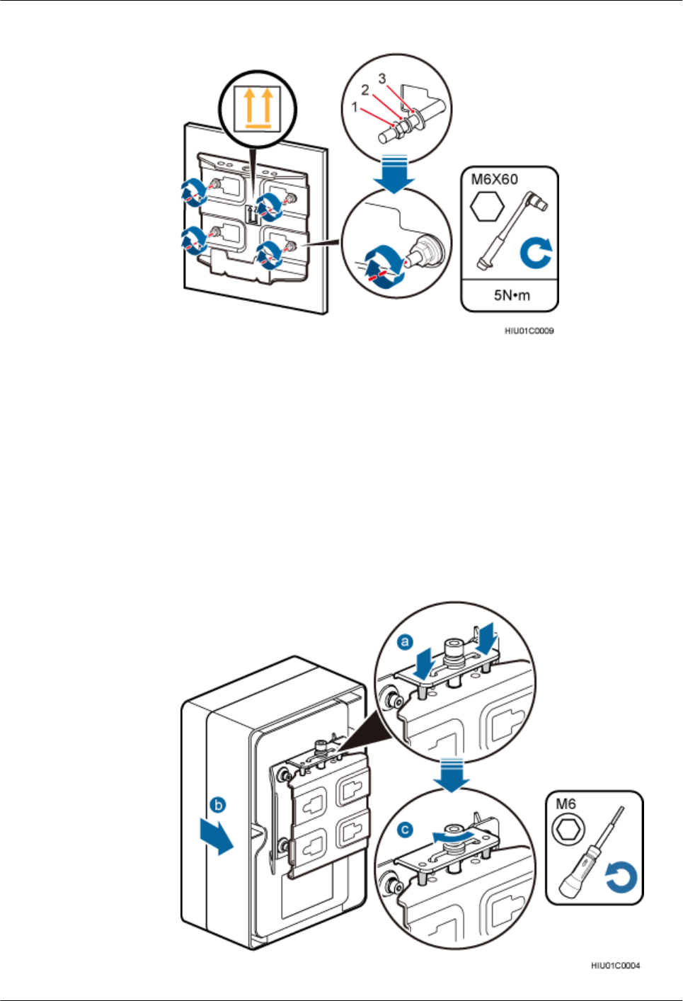
Figure 6-3 Tightening a mounting bracket to the installation position on a wall
(1) Nut (2) Spring washer (3) Flat washer
4. Fit the two dowels on the top of the ODM backplane into the mounting bracket, and
push the ODM case until it is attached onto the mounting bracket, as shown by
illustrations a and b in the following figure.
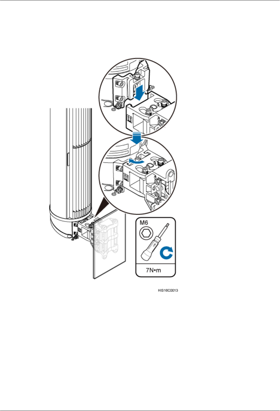
5. Use a double-headed inner hexagon tool to tighten the screw on the top of the
attachment plate clockwise to 7 N·m (61.95 lbf·in.), as shown by illustration c in the
following figure.
Figure 6-4 Installing an ODM to a mounting bracket
AAU3940
Installation Guide 6 (Optional) Installing an ODM
Issue 01 (2015-01-15) Huawei Proprietary and Confidential
Copyright © Huawei Technologies Co., Ltd.
27
lInstalling an ODM on a pole
1. Determine a position for installing an ODM on a pole, attach a mounting bracket to
the installation position on the pole, put the steel belts through the mounting bracket,
and wind the steel belts round the pole for one circle, as shown by illustrations a, b,
and c in the following figure.
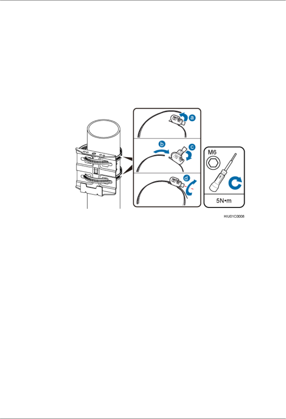
2. Use an M6 inner hexagon wrench to tighten the bolts on the two steel belts alternately
to secure the mounting bracket to 5 N·m (44.25 lbf·in.), as shown by illustration d in
the following figure.
Figure 6-5 Securing a mounting bracket to a pole
3. Fit the two dowels on the top of the ODM backplane into the mounting bracket, and
push the ODM case until it is attached onto the mounting bracket, as shown by
illustrations a and b in the following figure.
4. Use a double-headed inner hexagon tool to tighten the screw on the top of the
attachment plate clockwise to 7 N·m (61.95 lbf·in.), as shown by illustration c in the
following figure.
AAU3940
Installation Guide 6 (Optional) Installing an ODM
Issue 01 (2015-01-15) Huawei Proprietary and Confidential
Copyright © Huawei Technologies Co., Ltd.
28
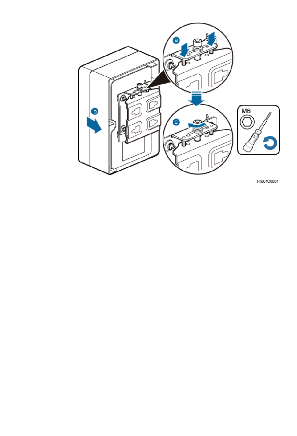
Figure 6-6 Installing an ODM to a mounting bracket
----End
AAU3940
Installation Guide 6 (Optional) Installing an ODM
Issue 01 (2015-01-15) Huawei Proprietary and Confidential
Copyright © Huawei Technologies Co., Ltd.
29
7 Preprocessing the AAU Maintenance Cavity
Before installing an AAU, take power terminals out of its maintenance cavity and install optical
modules.
Procedure
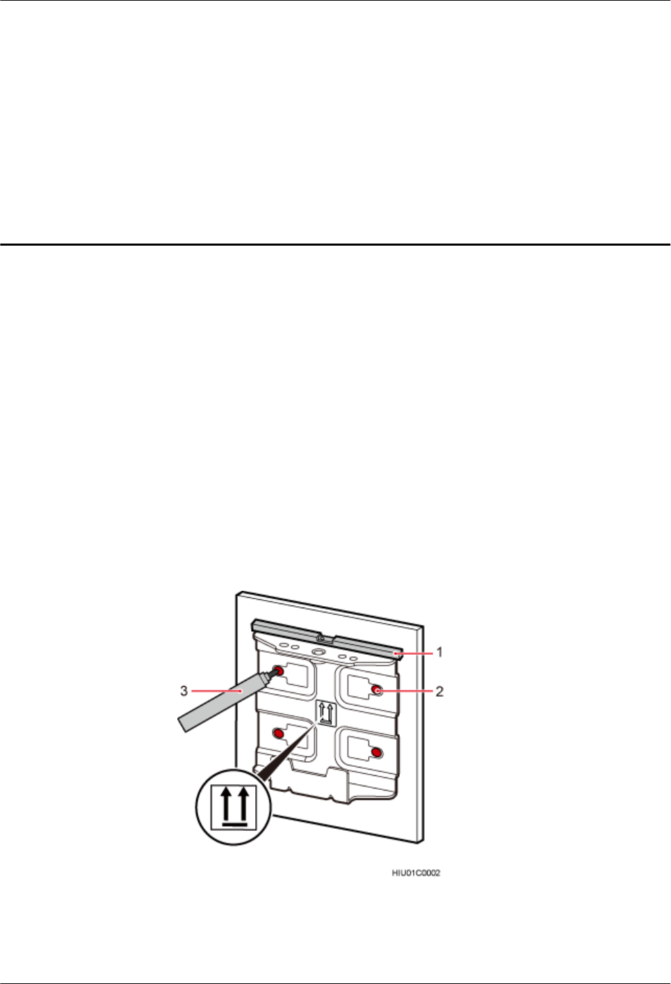
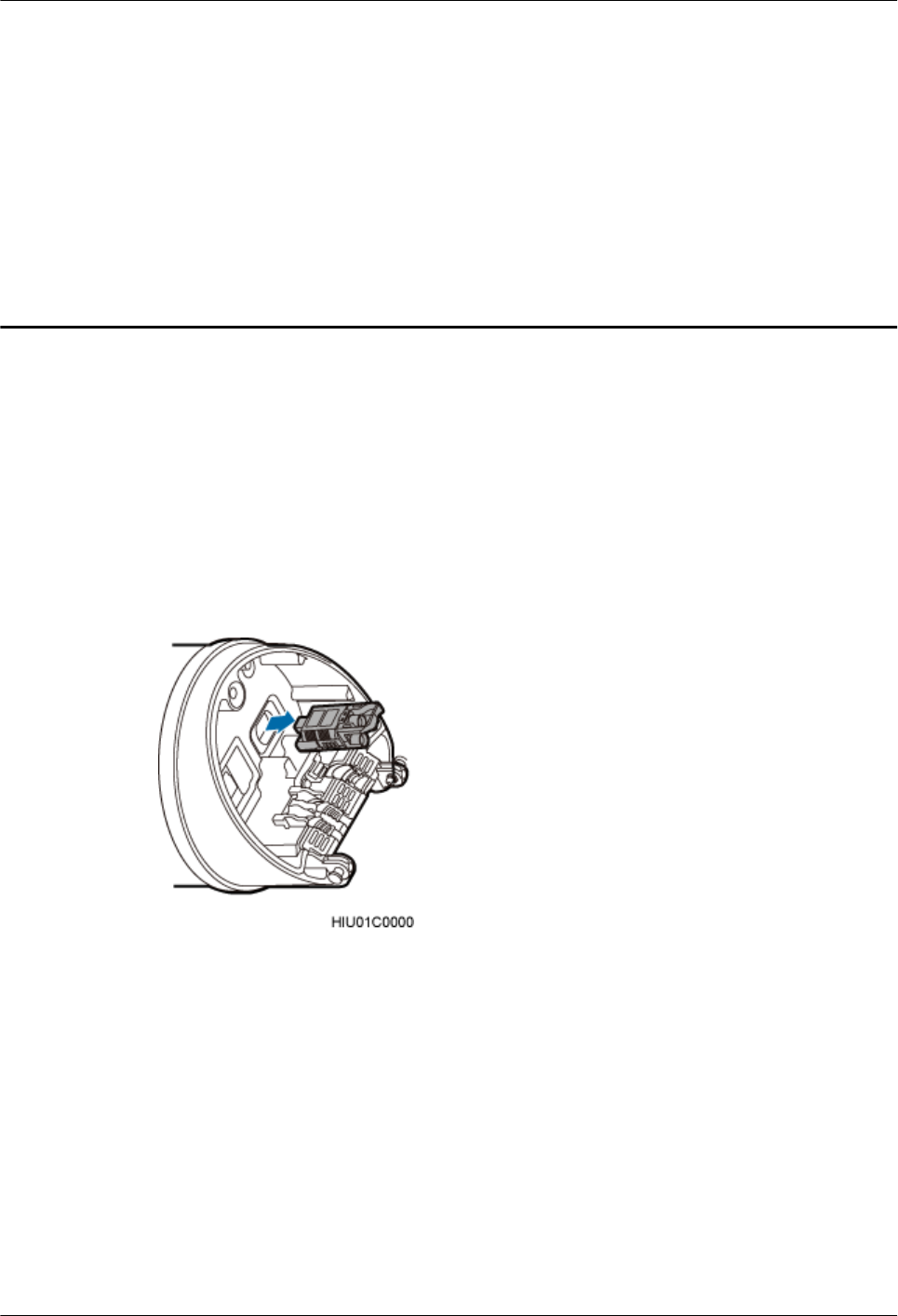
Step 1 Use an M6 inner hexagon torque screwdriver to loosen the screw on the maintenance cavity and
open the maintenance cavity. Then take out of power terminals, as shown in the following figure.
Figure 7-1 Taking out of power terminals
Step 2 Prepare power cables according to the instructions in 16.2 Adding a Tool-Less Female
Connector (Pressfit Type) to an AAU Power Cable on the AAU Side
Step 3 Lower the puller of the optical module, insert the optical module into the CPRI port on the AAU,
and raise the puller, as shown in the following figure.
AAU3940
Installation Guide 7 Preprocessing the AAU Maintenance Cavity
Issue 01 (2015-01-15) Huawei Proprietary and Confidential
Copyright © Huawei Technologies Co., Ltd.
30
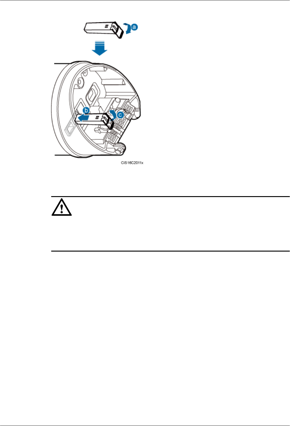
Figure 7-2 Installing the optical module
NOTICE
The performance of an optical module may deteriorate if it is exposed to the air for more than
20 minutes. Therefore, insert a fiber optic cable into an unpacked optical module within 20
minutes.
Step 4 Use an M6 inner hexagon torque screwdriver to tighten the screw on the maintenance cavity to
7 N·m (61.95 lbf·in.), as shown in the following figure.
AAU3940
Installation Guide 7 Preprocessing the AAU Maintenance Cavity
Issue 01 (2015-01-15) Huawei Proprietary and Confidential
Copyright © Huawei Technologies Co., Ltd.
31
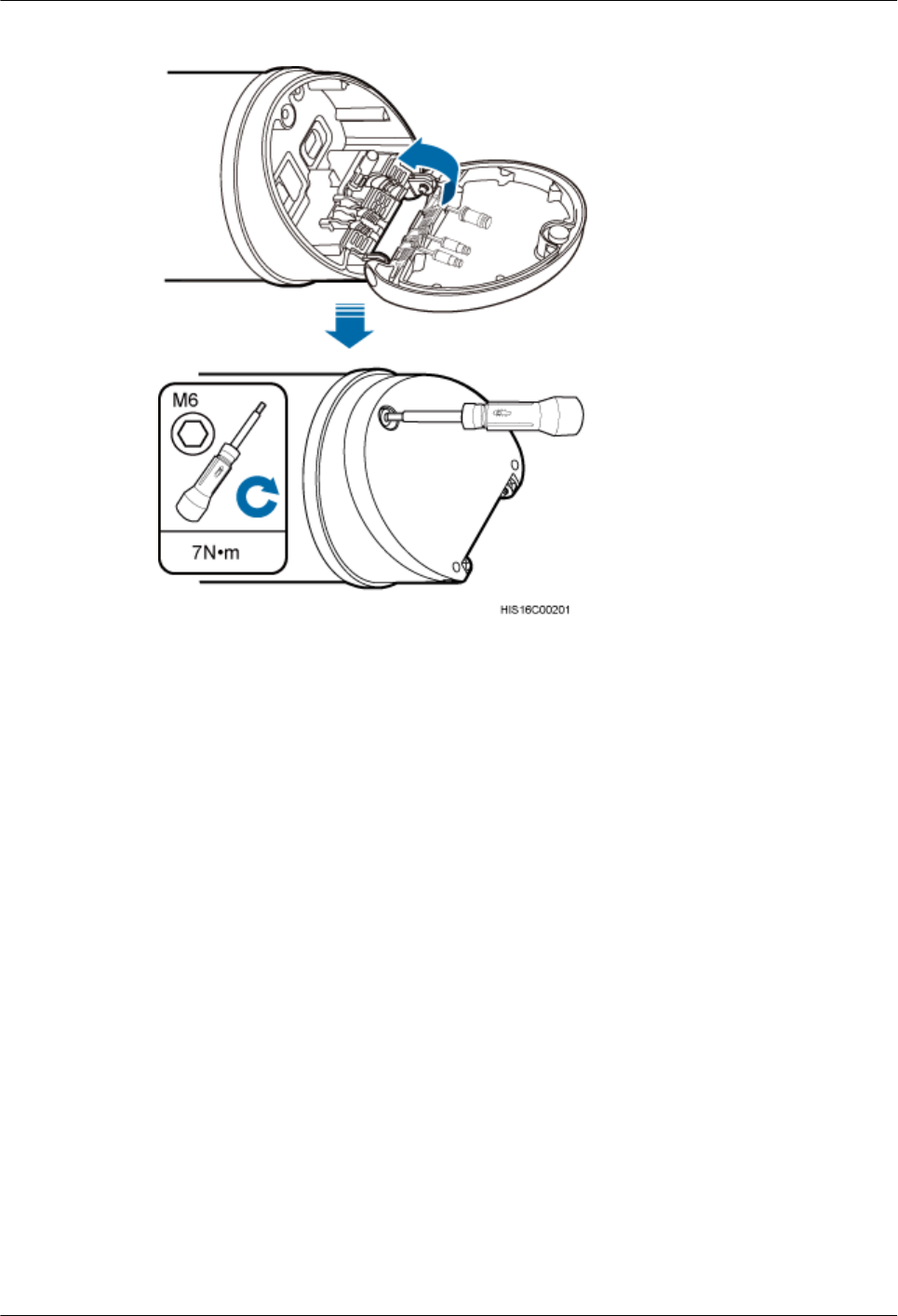
Figure 7-3 Closing a maintenance cavity
Step 5 Install the attachment plate on the maintenance cavity of the AAU to be installed, and use an
M6 inner hexagon torque screwdriver to tighten the screws to 7 N·m (61.95 lbf·in.), as shown
in the following figure.
AAU3940
Installation Guide 7 Preprocessing the AAU Maintenance Cavity
Issue 01 (2015-01-15) Huawei Proprietary and Confidential
Copyright © Huawei Technologies Co., Ltd.
32
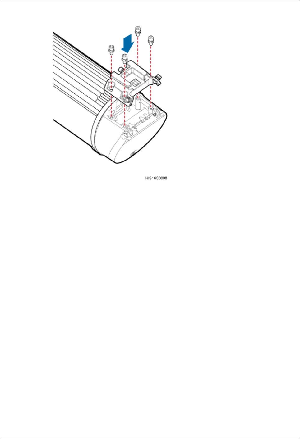
Figure 7-4 Installing an attachment plate
----End
AAU3940
Installation Guide 7 Preprocessing the AAU Maintenance Cavity
Issue 01 (2015-01-15) Huawei Proprietary and Confidential
Copyright © Huawei Technologies Co., Ltd.
33
8 Lifting an AAU
Before installing an AAU on a pole, you need to lift the AAU to the installation position on the
pole.
Prerequisites
You have preprocessed the AAU maintenance cavity. For detailed operations, see 7
Preprocessing the AAU Maintenance Cavity.
Context
It is recommended that a tail-lift truck be used to lift installation personnel and equipment to the
installation position. If there is no tail-lift truck, a reliable and safe scaffold can be used.
NOTICE
Do not work at heights when you meet any of the following situations:
lThunder, lightning, rain, or wind greater than force 6 occurs.
lWater remains on the surface of the steel tube.
lThere may be other danger.
After the above situations are eliminated, the Huawei security director and related technical
personnel must check all devices to be used before work start.
Procedure
Step 1 Installation person A lifts and places the bound mounting kits to the scaffold platform, as shown
in the following figure.
AAU3940
Installation Guide 8 Lifting an AAU
Issue 01 (2015-01-15) Huawei Proprietary and Confidential
Copyright © Huawei Technologies Co., Ltd.
34
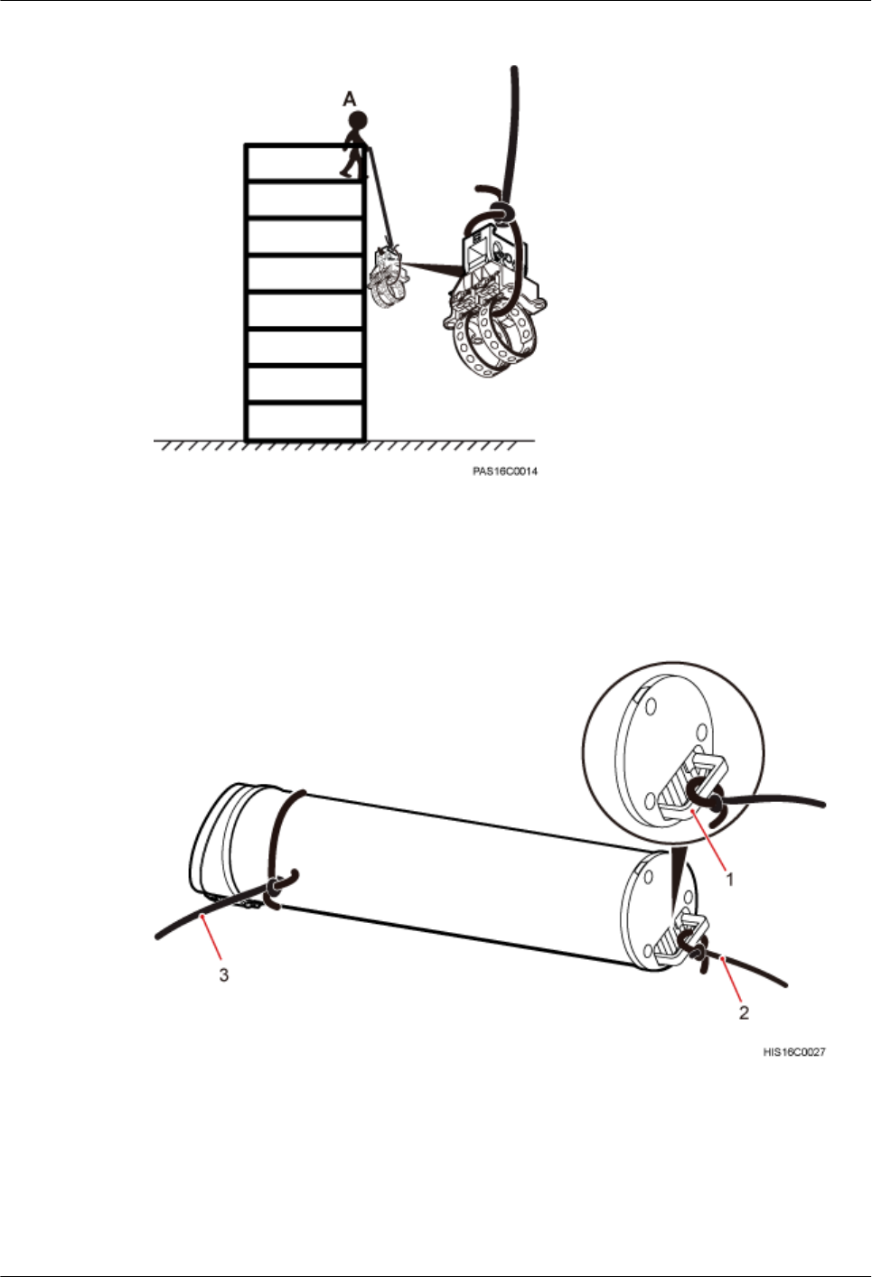
Figure 8-1 Lifting mounting kits
Step 2 Use the lifting sling to bind the handle on the top of the AAU and use the traction sling to bind
the lower part of the AAU, as shown in the following figure.
Figure 8-2 Binding an AAU
(1) Handle on the top (2) Lifting sling (3) Traction sling
Step 3 Installation person A climbs up onto the scaffold and then lifts and places the AAU on the
scaffold platform, and installation person B pulls the traction sling outwards to prevent the AAU
from colliding with the scaffold, as shown in the following figure.
AAU3940
Installation Guide 8 Lifting an AAU
Issue 01 (2015-01-15) Huawei Proprietary and Confidential
Copyright © Huawei Technologies Co., Ltd.
35
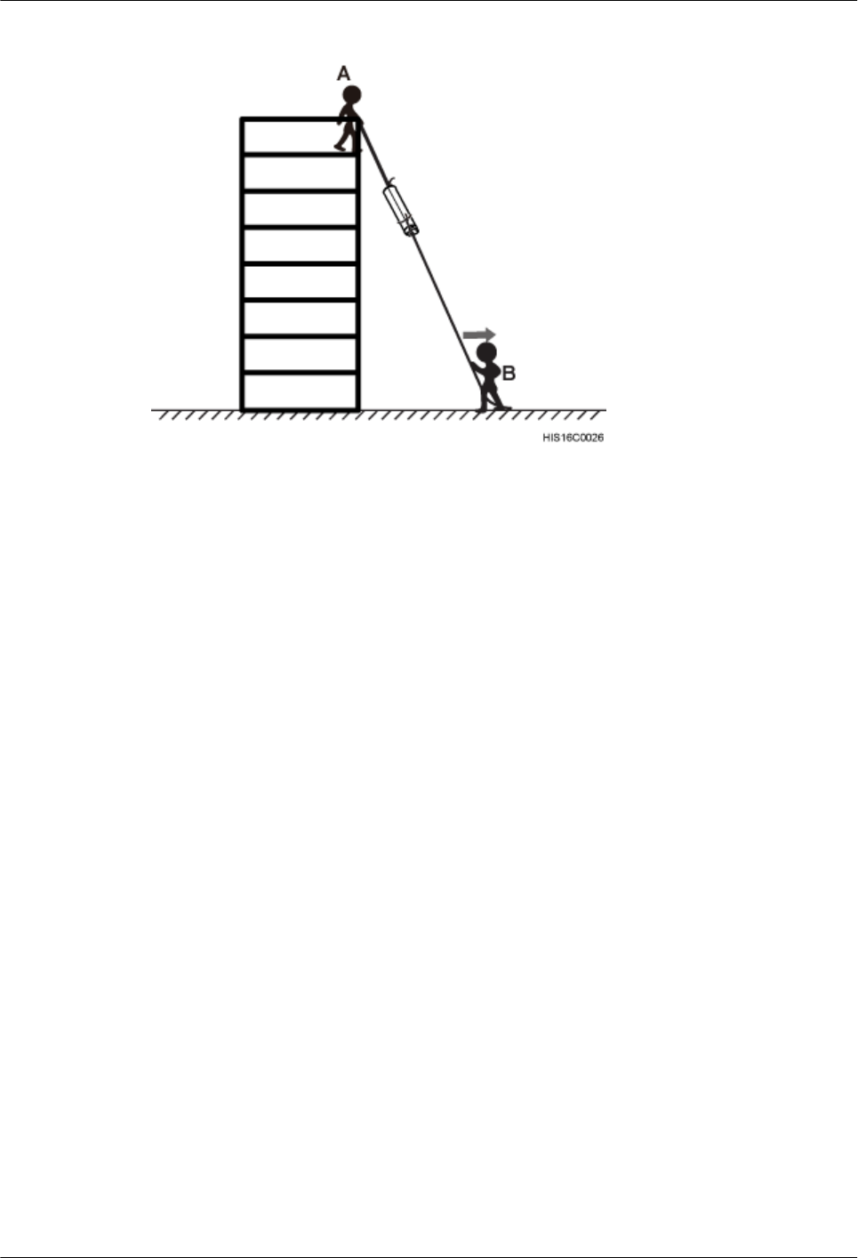
Figure 8-3 Lifting an AAU
----End
AAU3940
Installation Guide 8 Lifting an AAU
Issue 01 (2015-01-15) Huawei Proprietary and Confidential
Copyright © Huawei Technologies Co., Ltd.
36

9 Installing an AAU
About This Chapter
This chapter describes the procedures for installing an AAU in different scenarios.
9.1 Installing an AAU on a Pole
This section describes the procedure and precautions for installing an AAU on a pole.
9.2 Installing an AAU on the Top of a Pole
This section describes the procedure and precautions for installing an AAU on the top of a pole.
9.3 Installing an AAU on a Wall
This section describes the procedure and precautions for installing an AAU on a wall.
AAU3940
Installation Guide 9 Installing an AAU
Issue 01 (2015-01-15) Huawei Proprietary and Confidential
Copyright © Huawei Technologies Co., Ltd.
37
9.1 Installing an AAU on a Pole
This section describes the procedure and precautions for installing an AAU on a pole.
Prerequisites
lYou have preprocessed the AAU maintenance cavity. For detailed operations, see 7
Preprocessing the AAU Maintenance Cavity.
lYou have lifted the AAU and mounting kits to the installation position on the pole. For
detailed operations, see 8 Lifting an AAU.
Context
NOTICE
Do not work at heights when you meet any of the following situations:
lThunder, lightning, rain, or wind greater than force 6 occurs.
lWater remains on the surface of the steel tube.
lThere may be other danger.
After the above situations are eliminated, the Huawei security director and related technical
personnel must check all devices to be used before work start.
Procedure
Step 1 Determine a position for installing the mounting kits on a pole.
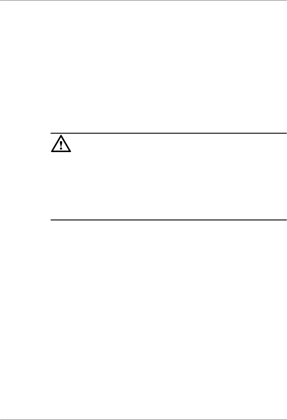
Step 2 Attach the mounting kits to the installation position on the pole, wind each steel belt round the
pole for one circle, and put the steel belt through the sliding block of the mounting kits, as shown
in the following figure.
AAU3940
Installation Guide 9 Installing an AAU
Issue 01 (2015-01-15) Huawei Proprietary and Confidential
Copyright © Huawei Technologies Co., Ltd.
38
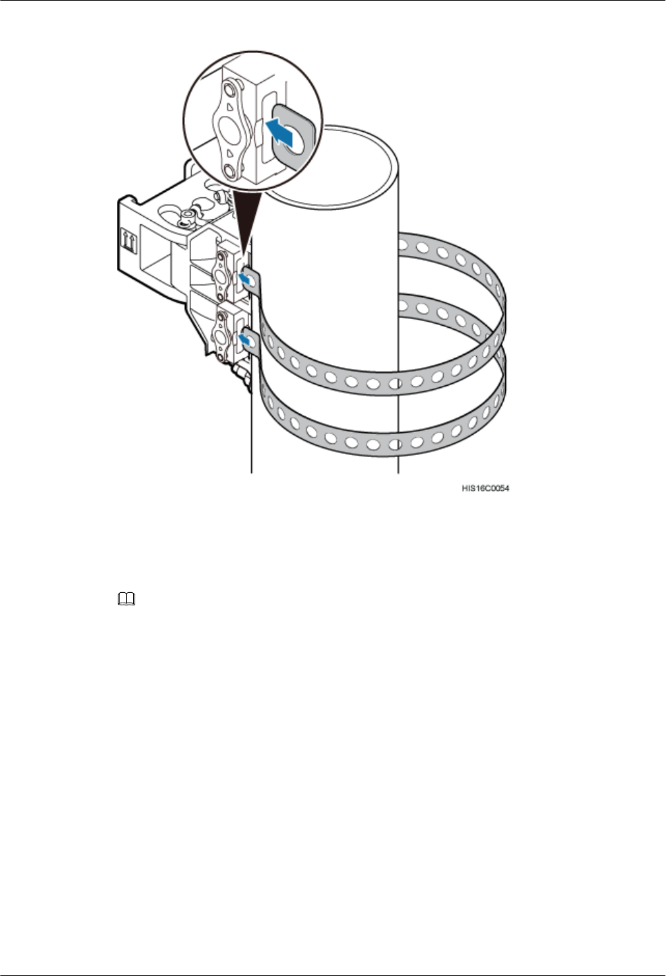
Figure 9-1 Putting the steel belt through the sliding block
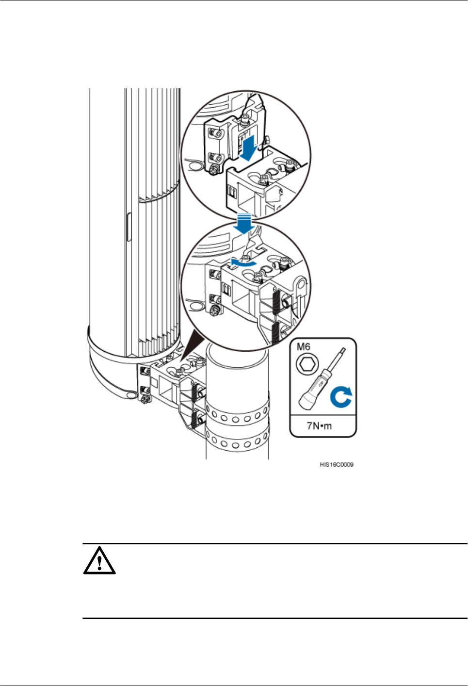
Step 3 Pull the steel belts to align the holes on the steel belts with those on the sliding blocks, as shown
in the following figure.
NOTE
If the pin on a sliding block is located between two holes on a steel belt after the belt is securely attached
to the pole, slightly loosen the steel belt so that the pin goes through a hole on the steel belt.
AAU3940
Installation Guide 9 Installing an AAU
Issue 01 (2015-01-15) Huawei Proprietary and Confidential
Copyright © Huawei Technologies Co., Ltd.
39
Figure 9-2 Installing the main mounting bracket
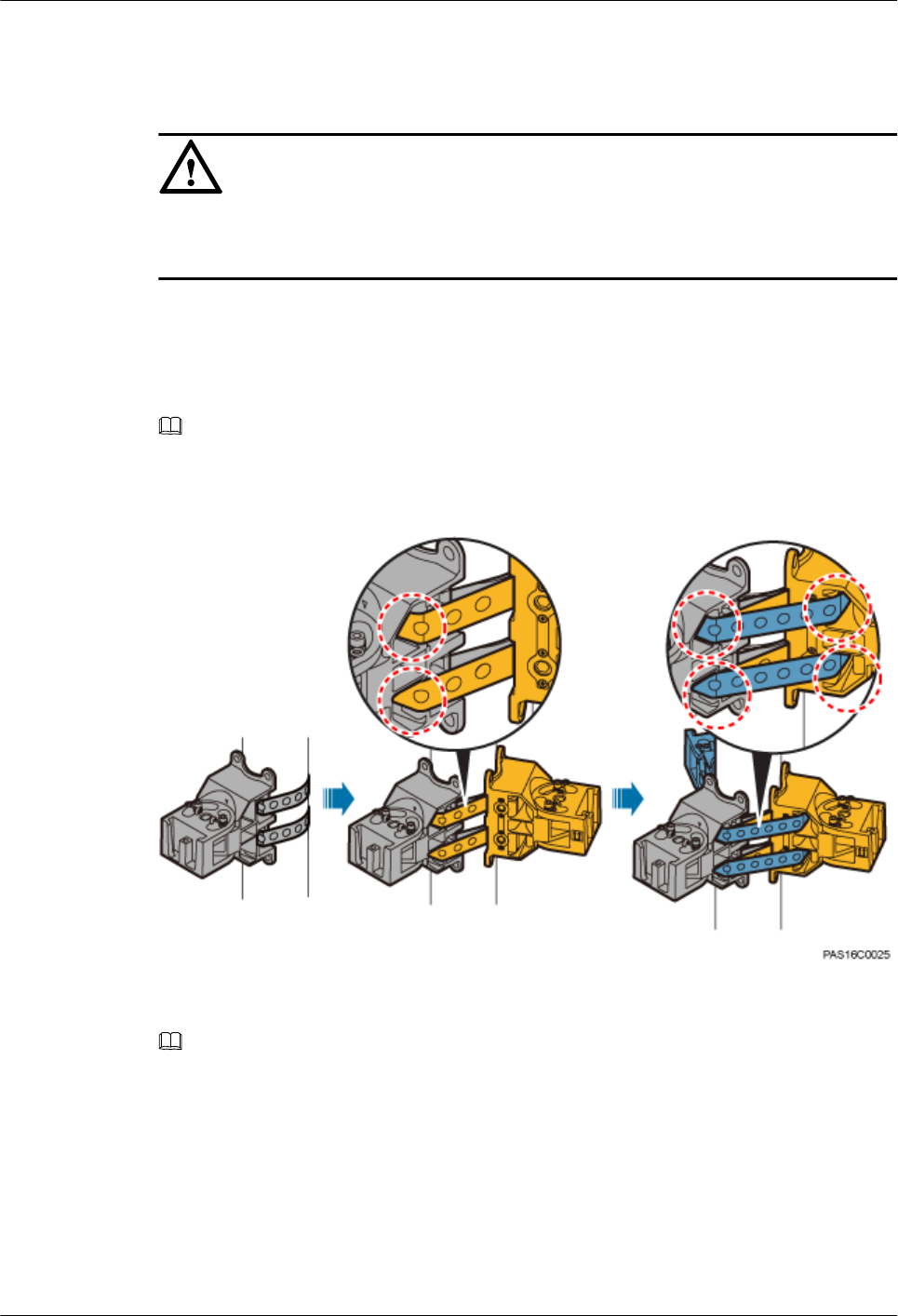
Step 4 Use an M10 inner hexagon wrench to tighten the bolts on the two steel belts alternately to secure
the main mounting bracket to 28 N·m (247.8 lbf·in.), as shown in the following figure.
NOTE
Tighten the bolts clockwise to slide a sliding block on a steel belt towards bolt heads and securely attach the
steel belt.
AAU3940
Installation Guide 9 Installing an AAU
Issue 01 (2015-01-15) Huawei Proprietary and Confidential
Copyright © Huawei Technologies Co., Ltd.
40
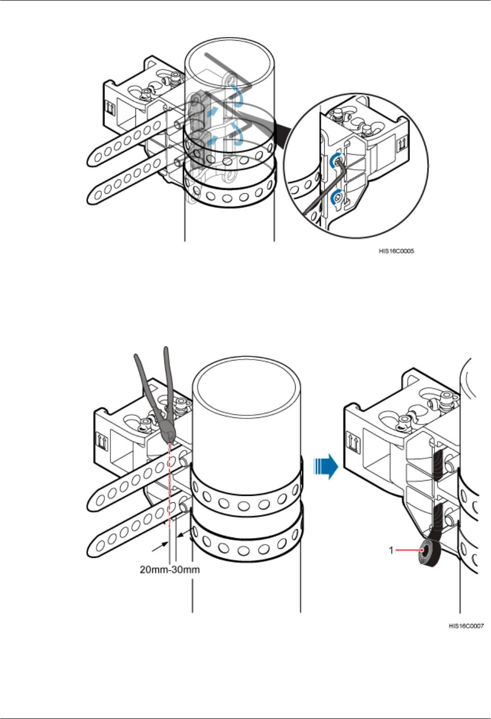
Figure 9-3 Securing a main mounting bracket
Step 5 Use a cable cutter to cut off the excess of steel belts and reserve a slack of 20 mm to 30 mm
(0.79 in. to 1.18 in.), and wrap insulation tape around the ends of the belts to prevent personal
injury, as shown in the following figure.
Figure 9-4 Cutting off the excess of steel belts and wrapping insulation tape
(1) Insulation tape
AAU3940
Installation Guide 9 Installing an AAU
Issue 01 (2015-01-15) Huawei Proprietary and Confidential
Copyright © Huawei Technologies Co., Ltd.
41
Step 6 Attach the AAU to the main mounting bracket, and use an M6 inner hexagon screwdriver to
tighten the screw on the main mounting bracket to 7 N·m (61.95 lbf·in.), as shown in the following
figure.
Figure 9-5 Installing an AAU on a main mounting bracket
Step 7 Optional: Install the second AAU.
NOTICE
Before installing the second AAU, ensure that the mounting kits for the first AAU have been
securely installed.
1. Put the steel belts of the mounting kits for the second AAU through the evading holes of
the mounting kits for the first AAU, as shown in the following figure.
2. Install the mounting kits for the AAU according to steps Step 3 to Step 5.
AAU3940
Installation Guide 9 Installing an AAU
Issue 01 (2015-01-15) Huawei Proprietary and Confidential
Copyright © Huawei Technologies Co., Ltd.
42
3. Install the AAU to the mounting kits according to Step 6.
Step 8 Optional: Install the third AAU.
NOTICE
Before installing the third AAU, ensure that the mounting kits for the first and second AAUs
have been securely installed.
1. Put the steel belts of the mounting kits for the third AAU through the evading holes of the
mounting kits for the first and second AAUs, as shown in the following figure.
2. Install the mounting kits for the AAU according to steps Step 3 to Step 5.
3. Install the AAU to the mounting kits according to Step 6.
NOTE
In the above figure, holes in dashed red circles are evading holes.
Figure 9-6 Putting the steel belts through the evading holes
NOTE
The following figure shows three AAUs installed on a pole.
AAU3940
Installation Guide 9 Installing an AAU
Issue 01 (2015-01-15) Huawei Proprietary and Confidential
Copyright © Huawei Technologies Co., Ltd.
43
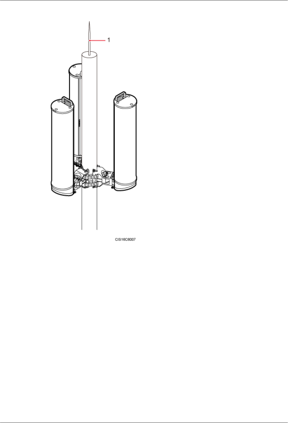
Figure 9-7 Three AAUs installed on a pole
(1) Lightning rod
----End
9.2 Installing an AAU on the Top of a Pole
This section describes the procedure and precautions for installing an AAU on the top of a pole.
Prerequisites
lYou have preprocessed the AAU maintenance cavity. For detailed operations, see 7
Preprocessing the AAU Maintenance Cavity.
AAU3940
Installation Guide 9 Installing an AAU
Issue 01 (2015-01-15) Huawei Proprietary and Confidential
Copyright © Huawei Technologies Co., Ltd.
44
Context
NOTICE
Do not work at heights when you meet any of the following situations:
lThunder, lightning, rain, or wind greater than force 6 occurs.
lWater remains on the surface of the steel tube.
lThere may be other danger.
After the above situations are eliminated, the Huawei security director and related technical
personnel must check all devices to be used before work start.
Procedure
Step 1 Lift the landscaping cover and remove it. Keep the landscaping cover for later installation.
Step 2 Use a torque wrench to tighten three M10 screws to 28 N·m (247.8 lbf·in.) so that the mounting
bracket is secured to the top of a pole, as shown in the following figure.
AAU3940
Installation Guide 9 Installing an AAU
Issue 01 (2015-01-15) Huawei Proprietary and Confidential
Copyright © Huawei Technologies Co., Ltd.
45
Figure 9-8 Securing a mounting bracket
Step 3 Put the AAU on the mounting bracket on the top of a pole with both hands, and tighten four M6
inner hexagon bolts to secure the AAU, a shown in the following figure.
AAU3940
Installation Guide 9 Installing an AAU
Issue 01 (2015-01-15) Huawei Proprietary and Confidential
Copyright © Huawei Technologies Co., Ltd.
46
Figure 9-9 Installing an AAU
Step 4 Install the removed landscaping cover.
NOTE
It is recommended that the landscaping cover be installed after cables are connected.
1. Put the landscaping cover on the AAU, and press the elastomer on the mounting bracket
when the landscaping cover reaches the top of the mounting bracket so that it can slide
down.
2. Ensure that the three support braces of the landscaping cover slide into the troughs on the
bottom of the mounting bracket.
AAU3940
Installation Guide 9 Installing an AAU
Issue 01 (2015-01-15) Huawei Proprietary and Confidential
Copyright © Huawei Technologies Co., Ltd.
47
Figure 9-10 Installing a landscaping cover
(1) Elastomer (2) Trough (3) Support brace
----End
9.3 Installing an AAU on a Wall
This section describes the procedure and precautions for installing an AAU on a wall.
Prerequisites
lYou have preprocessed the AAU maintenance cavity. For detailed operations, see 7
Preprocessing the AAU Maintenance Cavity.
AAU3940
Installation Guide 9 Installing an AAU
Issue 01 (2015-01-15) Huawei Proprietary and Confidential
Copyright © Huawei Technologies Co., Ltd.
48

Procedure
Step 1 Remove the steel belts from mounting kits, as shown in the following figure.
1. Use a Phillips screwdriver to remove four screws from the cover plate.
2. Use an M6 inner hexagon wrench to remove the bolts from the steel belts.
3. Remove the steel belts from the mounting kits.
AAU3940
Installation Guide 9 Installing an AAU
Issue 01 (2015-01-15) Huawei Proprietary and Confidential
Copyright © Huawei Technologies Co., Ltd.
49
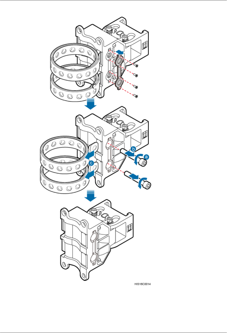
Figure 9-11 Removing steel belts
Step 2 Place the main bracket against the wall, use a level to verify that the main bracket is placed
horizontally, and use a maker to mark anchor points, as shown in the following figure.
AAU3940
Installation Guide 9 Installing an AAU
Issue 01 (2015-01-15) Huawei Proprietary and Confidential
Copyright © Huawei Technologies Co., Ltd.
50
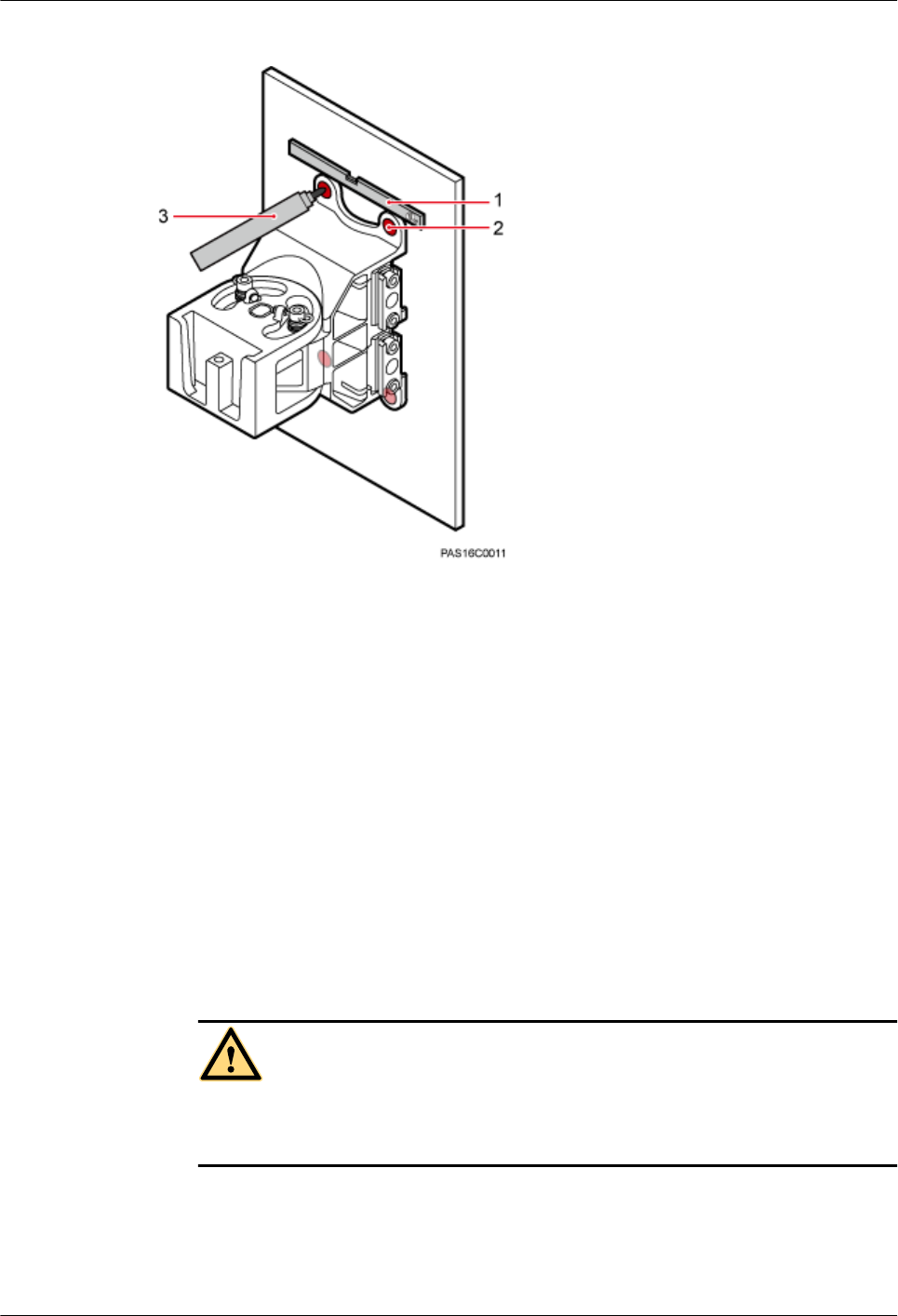
Figure 9-12 Marking anchor points
(1) Level (2) Screw hole (3) Marker
Step 3 Drill holes at the anchor points, and then insert expansion anchor bolts, as shown in the following
figure.
1. Use a hammer drill with a Φ10 bit to drill holes vertically at the marked anchor points.
Ensure that the depth of each hole ranges from 55 mm to 60 mm (2.17 in. to 2.36 in.).
2. Use a vacuum cleaner to clear the dust inside and around the holes, and measure the
distances between holes. If any of the holes is beyond the acceptable range, mark a new
anchor point and drill a new hole.
3. Tighten the expansion anchor bolts slightly and place one vertically into each hole.
4. Use a rubber mallet to hit the expansion bolt until the expansion tube completely enters the
hole.
5. Remove the nut, spring washer, and flat washer in sequence.
CAUTION
Take proper safety measures to protect your eyes and respiratory tract against the dust
before drilling holes.
AAU3940
Installation Guide 9 Installing an AAU
Issue 01 (2015-01-15) Huawei Proprietary and Confidential
Copyright © Huawei Technologies Co., Ltd.
51
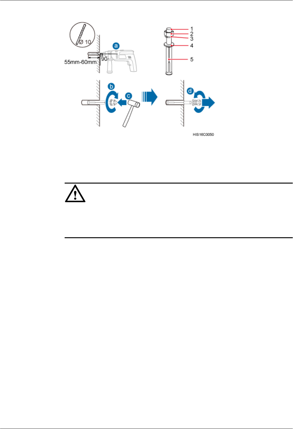
Figure 9-13 Drilling a hole and inserting expansion anchor bolts
(1) M8x80 bolt (2) Nut (3) Spring washer (4) Flat washer (5) Expansion tube
NOTICE
After dismantling an expansion anchor bolt, ensure that the top of the expansion tube is on
the same level as the wall. Otherwise, the main mounting bracket cannot be installed on
the wall evenly and securely.
Step 4 Place the main mounting bracket against the wall, use a torque wrench to tighten four M8 bolts
to 13 N·m (115.06 lbf·in.) and so that the main mounting bracket is securely installed on the
wall, as shown in the following figure.
AAU3940
Installation Guide 9 Installing an AAU
Issue 01 (2015-01-15) Huawei Proprietary and Confidential
Copyright © Huawei Technologies Co., Ltd.
52
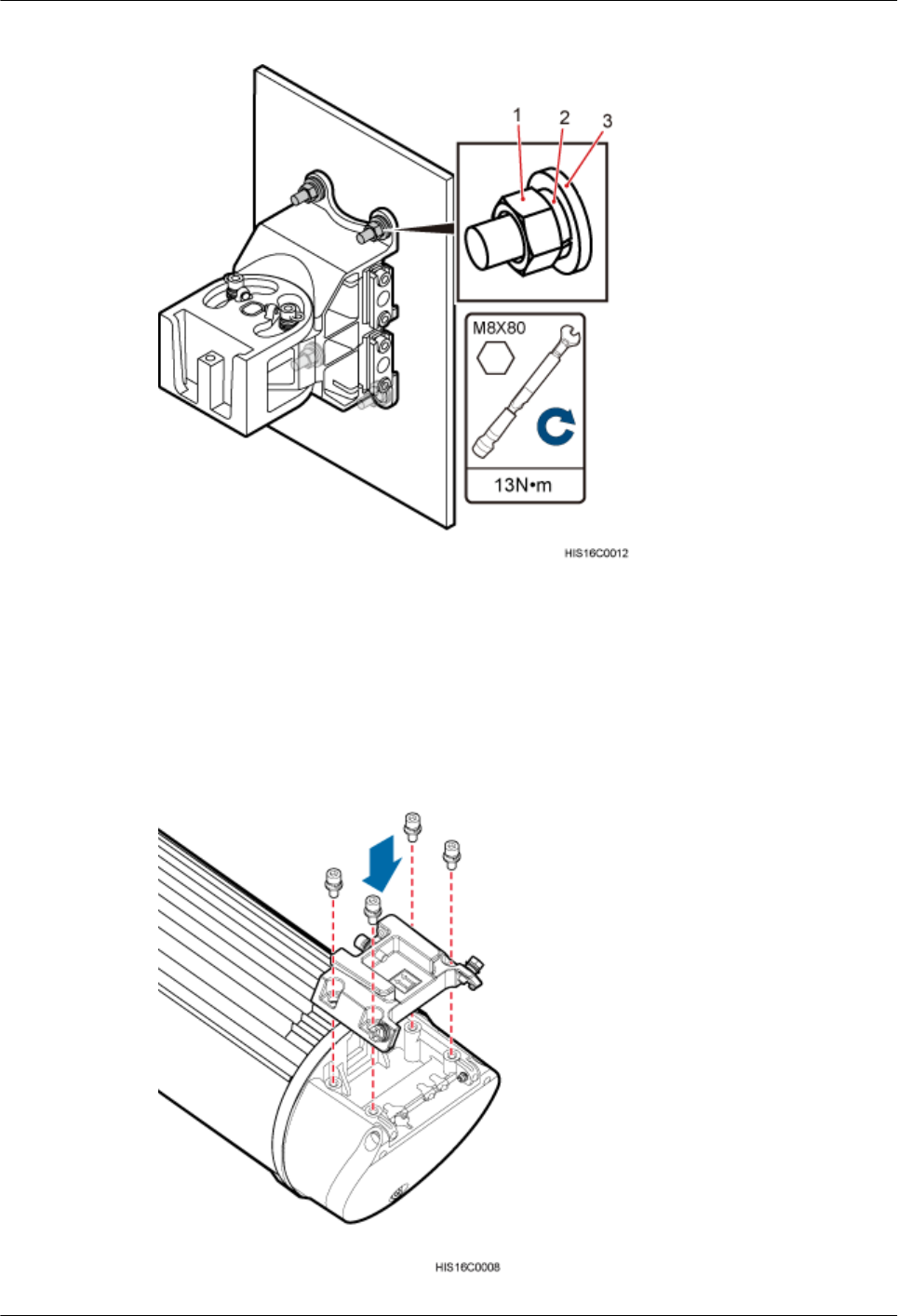
Figure 9-14 Installing the main mounting bracket
(1) Nut (2) Spring washer (3) Flat washer
Step 5 Install the attachment plate on the maintenance cavity of the AAU to be installed, and use an
M6 inner hexagon torque screwdriver to tighten the screws to 7 N·m (61.95 lbf·in.), as shown
in the following figure.
Figure 9-15 Installing an attachment plate
AAU3940
Installation Guide 9 Installing an AAU
Issue 01 (2015-01-15) Huawei Proprietary and Confidential
Copyright © Huawei Technologies Co., Ltd.
53
Step 6 Attach the AAU to the main mounting bracket, and tighten the bolts on the main mounting
bracket, as shown in the following figure.
Figure 9-16 Installing an AAU on a main mounting bracket
----End
AAU3940
Installation Guide 9 Installing an AAU
Issue 01 (2015-01-15) Huawei Proprietary and Confidential
Copyright © Huawei Technologies Co., Ltd.
54

10 Installing AAU Cables
About This Chapter
This section describes the procedure and precautions for installing AAU cables.
10.1 Cabling Requirements
Cables must be laid out according to the specified cabling requirements to prevent signal
interference.
10.2 Installing an AAU PGND Cable
This section describes the procedure and precautions for installing an AAU PGND cable.
10.3 Installing an AAU Power Cable
This section describes the process and precautions for installing an AAU power cable.
10.4 Installing an ODM Power Cable
This section describes the process and precautions for installing an ODM power cable when an
ODM is configured.
10.5 Installing a Trunk CPRI Fiber Optic Cable Between an ODM and a BBU
This section describes the procedure for installing a trunk CPRI fiber optic cable between an
ODM and a BBU when an ODM is configured.
10.6 Installing a CPRI Fiber Optic Cable Between an AAU and a BBU or Between an AAU and
an ODM
If no ODM is configured, a CPRI fiber optic cable is directly connected to a BBU. If an ODM
is configured, a CPRI fiber optic cable is connected to the ODM.
AAU3940
Installation Guide 10 Installing AAU Cables
Issue 01 (2015-01-15) Huawei Proprietary and Confidential
Copyright © Huawei Technologies Co., Ltd.
55

10.1 Cabling Requirements
Cables must be laid out according to the specified cabling requirements to prevent signal
interference.
NOTE
If a cable listed below is not required, skip the cabling requirements of the cable.
General Cabling Requirements
Bending radius requirements
lThe bending radius of a 7/8'' feeder must be greater than 250 mm (9.84 in.), and the bending
radius of a 5/4'' feeder must be greater than 380 mm (14.96 in.).
lThe bending radius of a 1/4'' jumper must be greater than 35 mm (1.38 in.). The bending
radius of a super-flexible 1/2'' jumper must be greater than 50 mm (1.97 in.), and the bending
radius of an ordinary 1/2'' jumper must be greater than 127 mm (5 in.).
lThe bending radius of a power cable or PGND cable must be at least three times its diameter.
lThe bending radius of a fiber optic cable is at least 20 times of its diameter, and the bending
radius of a breakout cable is at least 30 mm (1.18 in.).
lThe bending radius of an E1/T1 cable must be at least three times its diameter.
lThe bending radius of a signal cable must be at least five times its diameter.
Cable binding requirements
lCables of the same type must be bound together.
lDifferent types of cables must be separately laid out and bound, with a minimum distance
of 30 mm (1.18 in.) from each other.
lThe cables must be bound tightly and neatly. The sheaths of the cables must not be damaged.
lThe cable ties must face the same direction, and those at the same horizontal line must be
in a straight line.
lThe excess of the indoor cable ties is cut off. The excess of 5 mm (0.197 in.) of the outdoor
cable ties is reserved, and the cut surfaces are smooth without sharp edges.
lAfter cables are installed, labels or nameplates must be attached to the cables at their ends,
curves, and interconnection positions.
Security requirements
lWhen routing cables, avoid sharp objects, for example sharp edges on the wall. If necessary,
use tubes to protect the cables.
lWhen routing cables, keep the cables away from heat sources and use heat insulation
materials to insulate the cables from the heat sources.
lReserve a proper distance (0.1 m or 3.937 in. is recommended) between equipment and
cables especially at the cable curves to protect the cables and equipment.
Indoor cabling requirements
lRoute each cable into the room through the feeder window.
AAU3940
Installation Guide 10 Installing AAU Cables
Issue 01 (2015-01-15) Huawei Proprietary and Confidential
Copyright © Huawei Technologies Co., Ltd.
56

lReserve drip loops for all cables outside the feeder window before routing them into the
room. Ensure that the radiuses of the drip loops are greater than or equal to the minimum
bending radiuses of the cables.
lWhen routing a cable into the room, ensure that a person is assisting you in the room.
lApply waterproof treatment to the feeder window.
Outdoor Cabling Requirements
lAfter being connected to a ground clip on power cables, a ground cable must be routed
downwards to prevent water from entering the equipment to which the power cables
connect.
lProtect outdoor cables against potential damage. For example, put the cables through tubes.
lThe cables to be protected include AC power cables, transmission cables, and cables laid
out underground.
lWhen routing cables through tubes on the ground below the cabinet, put a 30 mm to 50
mm (1.18 in. to 1.97 in.) length of the tubes into the base of the cabinet but do not put the
tubes into the cabinet. Use waterproof tape or waterproof silicon gel to block both ends of
the tubes and use sheet metal tabs to secure the tubes to the cable holes in the base.
lWhen routing cables through tubes along a metal cable trough below the cabinet, do not
put the tubes into the base of the cabinet but cover the cable trough and connect the tubes
to the cable holes in the base.
lUse clips to secure cables outdoors. For the method of installing a clip, see the installation
guide delivered with the clip.
lArrange cables neatly along the routing direction and use clips to secure the cables.
lDetermine the positions where the clips are installed according to the actual situation. For
example, 7/8" feeders are secured with clips at an interval of 1.5 m to 2 m (4.92 ft to 6.56
ft), CPRI fiber optic cables and power cables are secured with clips at an interval of 1 m
to 1.5 m (3.28 ft to 4.92 ft). Ensure that the clips are evenly spaced and in the same direction.
lWhen fastening cables with a clip, ensure that the cables are aligned neatly and are routed
through the holes in the clip. Do not stretch the cables too tightly.
NOTE
There are two types of clips: 3-hole clip and 6-hole clip, which are described as follows:
lA 3-hole clip is shown by illustration a in the following figure. It is often used to fasten feeders.
lA 6-hole clip is shown by illustration b in the following figure. It is often used to fasten power cables and
CPRI fiber optic cables.
AAU3940
Installation Guide 10 Installing AAU Cables
Issue 01 (2015-01-15) Huawei Proprietary and Confidential
Copyright © Huawei Technologies Co., Ltd.
57
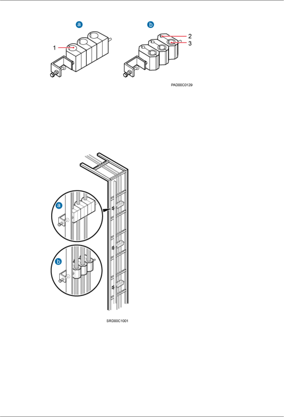
Figure 10-1 Exterior of the clips
(1) Cable hole for feeders (2) Cable hole for fiber optic cables (3) Cable hole for power cables
The following figure shows the cables secured on a cable tray.
Figure 10-2 Cables secured on a cable tray
(1) 3-hole clip (2) 6-hole clip
The following figure shows the cables secured on a tower.
AAU3940
Installation Guide 10 Installing AAU Cables
Issue 01 (2015-01-15) Huawei Proprietary and Confidential
Copyright © Huawei Technologies Co., Ltd.
58
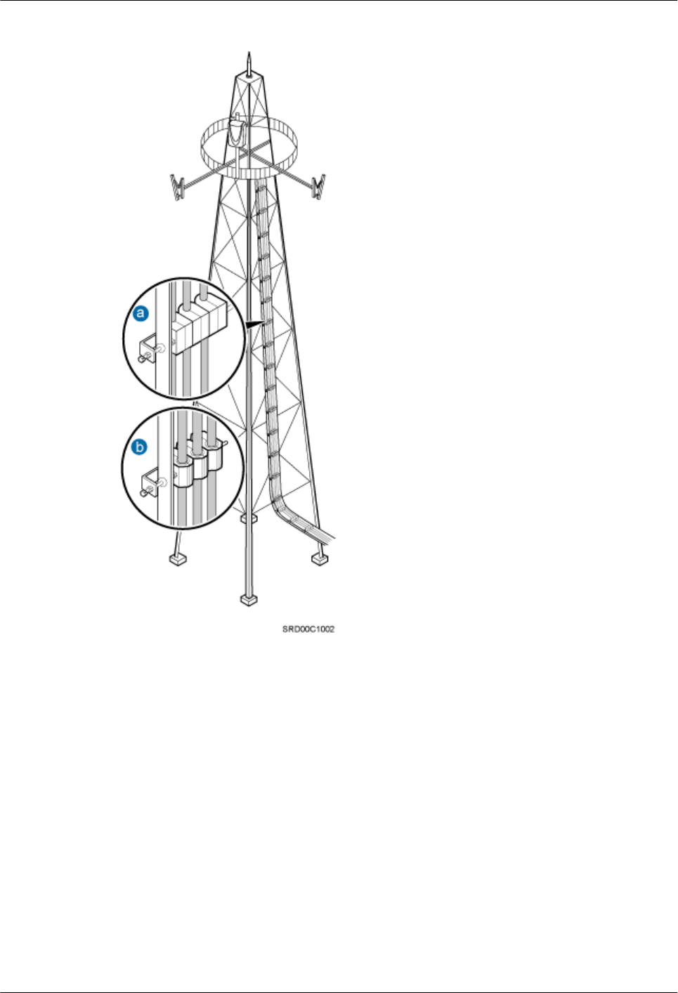
Figure 10-3 Cables secured on a tower
(1) 3-hole clip (2) 6-hole clip
Special Cabling Requirements
Cabling of power cables
lPower cables must be installed in the position specified in engineering design documents.
lIf the length of power cables is insufficient, replace the cables rather than adding connectors
or soldering joints to lengthen the cables.
lCables can only be laid out under well-planned instructions. The cabling activities of fiber
optic cables are allowed only when qualified personnel and communication facilities are
available.
lDo not circle and twist cables.
AAU3940
Installation Guide 10 Installing AAU Cables
Issue 01 (2015-01-15) Huawei Proprietary and Confidential
Copyright © Huawei Technologies Co., Ltd.
59
lAfter routing a DC power cable onto the platform on a tower, route it along the shortest
path to the rails surrounding the platform, and route it along the inside of the rails.
lAfter routing a DC power cable close to the equipment on a tower, use clips to secure the
power cable onto a pole or the rails surrounding the platform. Ensure that there is no
excessively long distance between the equipment and the position where the power cable
is secured.
Cabling of PGND cables
lPGND cables for a base station must be connected to the same group of ground bars.
lPGND cables must be buried in the ground or routed indoors.
lThe external conductor of the coaxial wire and the shield layer of the shielded cable must
have proper electrical contact with the metal surface of the equipment to which they are
connected.
lPGND cables and signal cables must be installed separately. A certain distance must be
reserved between them to prevent interference from each other.
lSwitches or fuses must not be installed on the PGND cables.
lOther devices must not be used for electrical connections of the PGND cables.
lAll the metal parts in the housing of the equipment must be reliably connected to the ground
terminal.
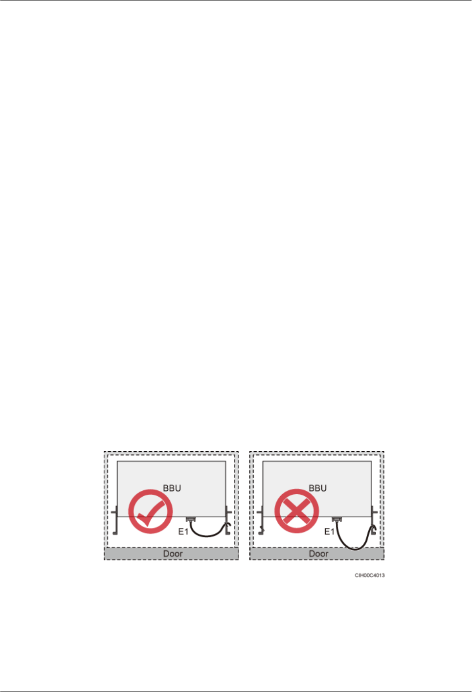
Cabling of E1 cables
lE1 cables must not cross power cables, PGND cables, or RF cables when laid out. If
transmission cables are laid out with power cables, PGND cables, or RF cables in parallel,
the spacing between them must be greater than 30 mm (1.18 in.).
lE1 cables are lined up straight and bound neatly with cable ties.
lSufficient slack is provided for E1 cables at turns.
lE1 cables must not be pressed by the door of the cabinet when routed, as shown in the
following figure.
Figure 10-4 E1 cables routed in the cabinet
Cabling of fiber optic cables
lAt least three people are required for laying out fiber optic cables. The cabling activities
of fiber optic cables are allowed only when qualified personnel and communication
facilities are available.
AAU3940
Installation Guide 10 Installing AAU Cables
Issue 01 (2015-01-15) Huawei Proprietary and Confidential
Copyright © Huawei Technologies Co., Ltd.
60
lThe operating temperature of fiber optic cables ranges from -40ºC to +60ºC (-40ºF to
+140ºF). If the actual temperature is beyond this range, take protective measures or select
another route.
lDo not circle and twist cables.
lDo not bind a fiber optic cable at the position where it bends.
lDo not stretch, step on, or place heavy objects on fiber optic cables. Keep the fiber optic
cables away from sharp objects.
lWhen fiber optic cables are routed, the excess of the fiber optic cables must be coiled around
special devices, such as a fiber coiler.
lAn unarmored fiber optic cable must be bound using binding straps. If a fiber optic patch
cord needs to be secured in a cabinet or a piece of equipment, use binding straps to bind it
and then use cable ties to secure the binding straps to the cabinet or equipment. Ensure that
the fiber optic cables can flexibly move in the cable ties. Do not bend the fiber optic cables
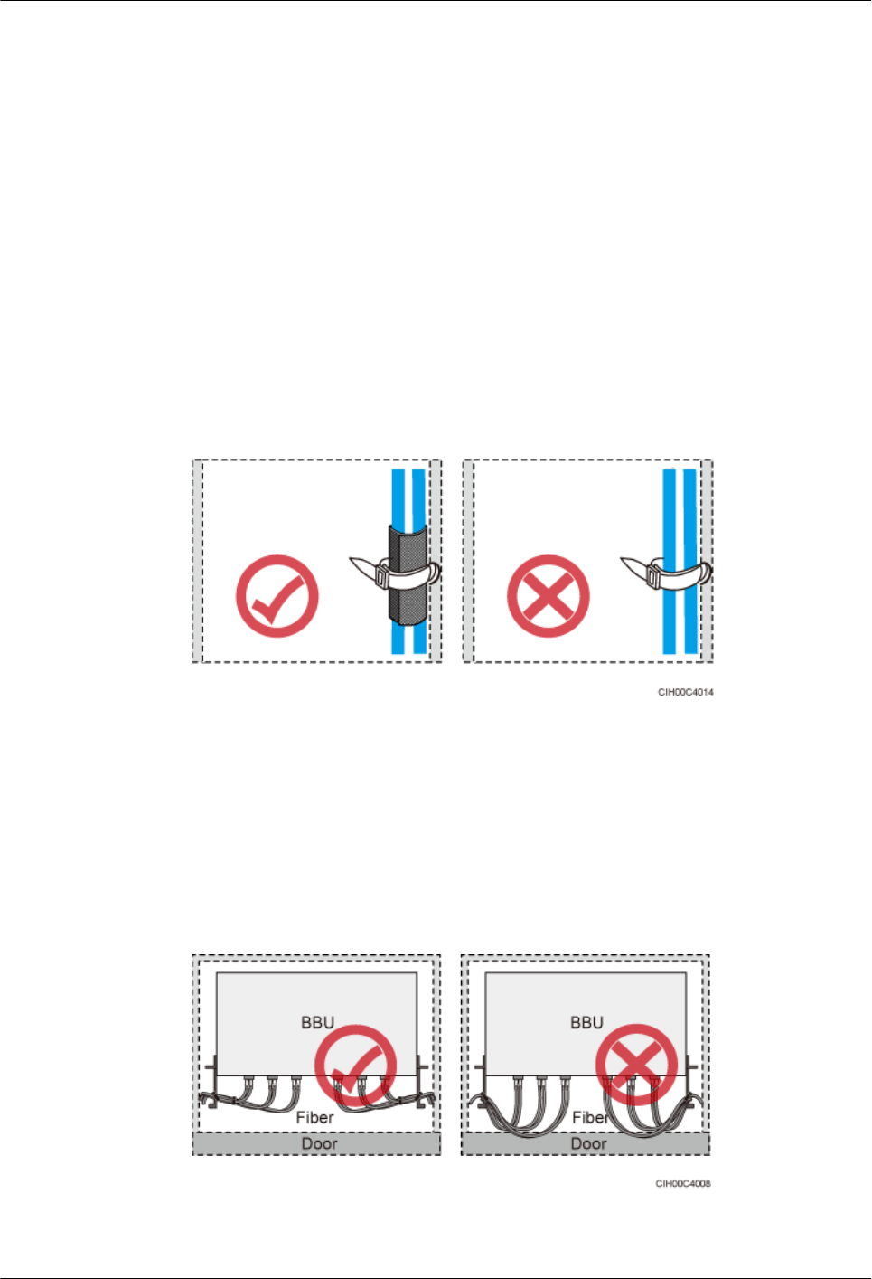
sharply. The following figure shows how to bind the fiber optic cables correctly.
Figure 10-5 Binding fiber optic cables
lWhen coiling fiber optic cables, apply even strength. Do not bend the fiber optic cables
with force.
lUnused optical connectors must be covered with dustproof caps.
lThe fiber optic cables must not be pressed by the door of the cabinet when routed, as shown
in the following figures.
Figure 10-6 CPRI fiber optic cables routed in the cabinet (1)
AAU3940
Installation Guide 10 Installing AAU Cables
Issue 01 (2015-01-15) Huawei Proprietary and Confidential
Copyright © Huawei Technologies Co., Ltd.
61
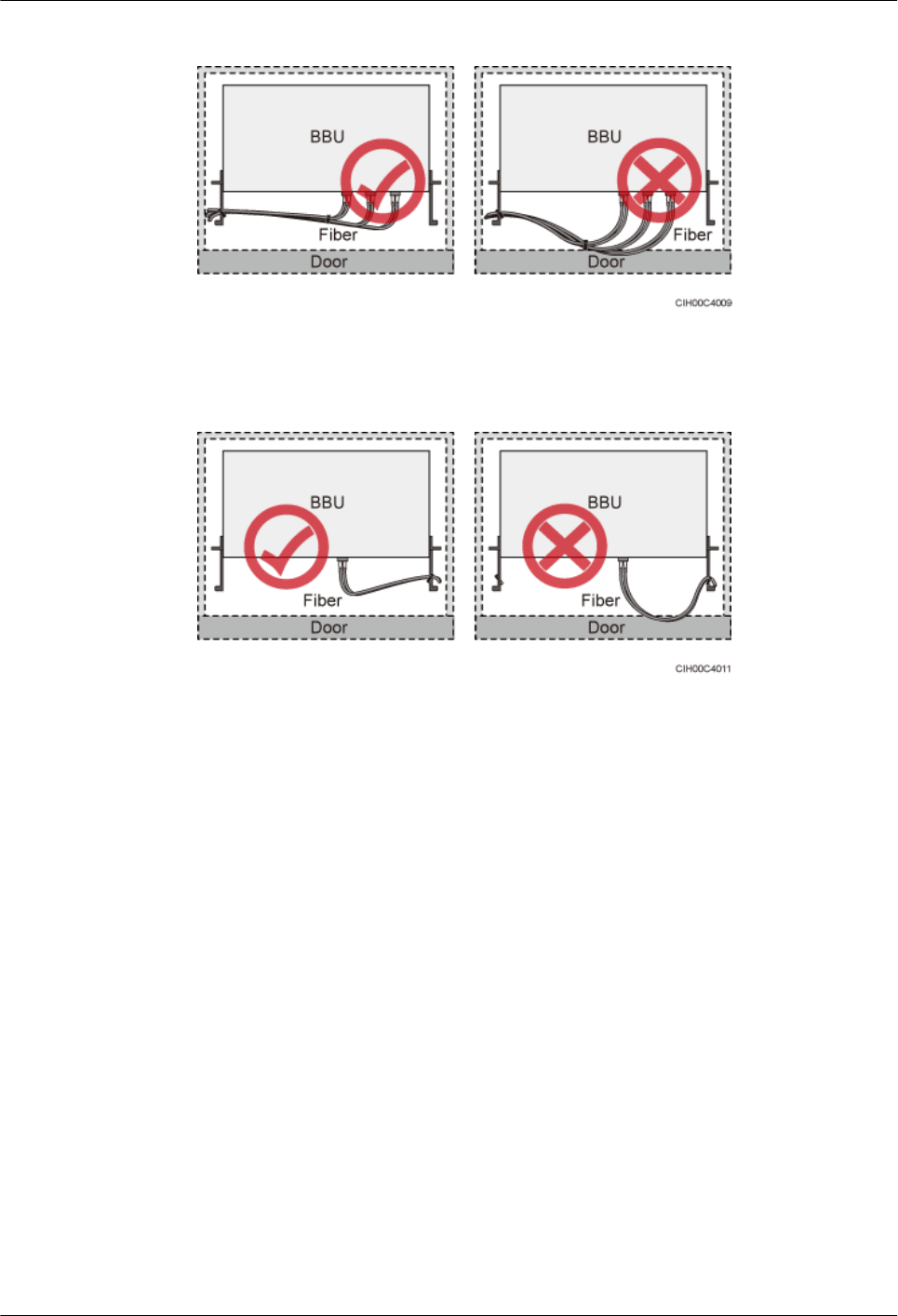
Figure 10-7 CPRI fiber optic cables routed in the cabinet (2)
Figure 10-8 FE/GE fiber optic cables routed in the cabinet
lAfter routing a fiber optic cable onto the platform on a tower, route it along the shortest
path to the rails surrounding the platform, and route it along the inside of the rails.
lAfter routing a fiber optic cable close to the equipment on a tower, use clips to secure the
fiber optic cable onto a pole or the rails surrounding the platform. Ensure that there is no
excessively long distance between the equipment and the position where the cable is
secured.
lCoil the excess of the fiber optic cables near the equipment on the tower before securing
the cables on the tower.
10.2 Installing an AAU PGND Cable
This section describes the procedure and precautions for installing an AAU PGND cable.
Context
The following table lists the specifications of an AAU PGND cable.
AAU3940
Installation Guide 10 Installing AAU Cables
Issue 01 (2015-01-15) Huawei Proprietary and Confidential
Copyright © Huawei Technologies Co., Ltd.
62

Table 10-1 Specifications of an AAU PGND cable
Cable End Connecting to
the AAU
End Connecting to
the Ground Bar
Color
AAU PGND cable OT terminal (M6, 16
mm2 or 0.025 in.2)
OT terminal (M8, 16
mm2 or 0.025 in.2)
Green and yellow
Procedure
Step 1 Prepare a PGND cable.
1. Cut the cables to the length suitable for the actual cable route.
2. Add OT terminals to both ends of the cables according to the instructions in Assembling
the OT Terminal and the Power Cable.
Step 2 Install the PGND cable.
1. Connect one end of the PGND cable with an M6 OT terminal to the ground bar of the
mounting kits for the AAU (shown by ), and use a torque wrench to tighten the ground
bolt to 4.8 N·m (42.48 lbf·in.).
Figure 10-9, Figure 10-10, and Figure 10-11 show the methods of installing PGND cables
when an AAU is installed on a pole, when an AAU is installed on a wall, and when an AAU
is installed on the top of a pole, respectively.
AAU3940
Installation Guide 10 Installing AAU Cables
Issue 01 (2015-01-15) Huawei Proprietary and Confidential
Copyright © Huawei Technologies Co., Ltd.
63
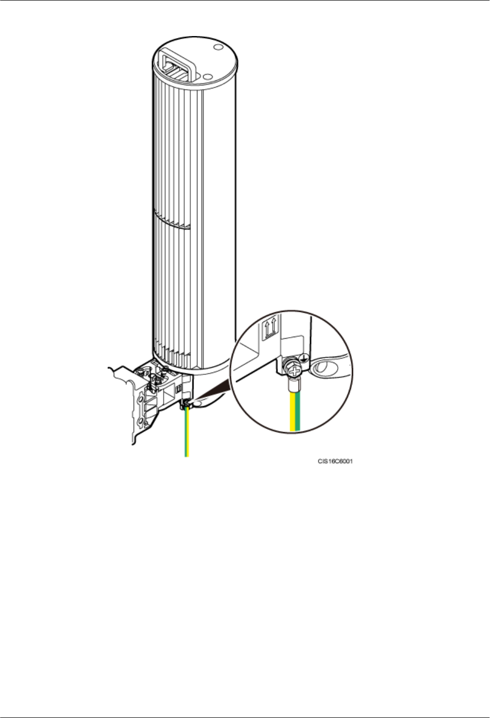
Figure 10-9 Installing a PGND cable when an AAU is installed on a pole
AAU3940
Installation Guide 10 Installing AAU Cables
Issue 01 (2015-01-15) Huawei Proprietary and Confidential
Copyright © Huawei Technologies Co., Ltd.
64

Figure 10-10 Installing a PGND cable when an AAU is installed on a wall
AAU3940
Installation Guide 10 Installing AAU Cables
Issue 01 (2015-01-15) Huawei Proprietary and Confidential
Copyright © Huawei Technologies Co., Ltd.
65
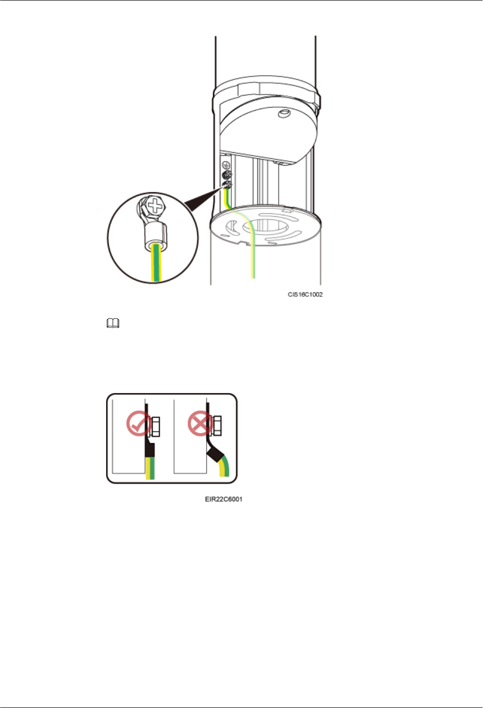
Figure 10-11 Installing a PGND cable when an AAU is installed on the top of a pole
NOTE
When installing a PGND cable, tightly press the OT terminal in the correct direction, as shown in
the following figure.
Figure 10-12 Installing an OT terminal correctly
2. Connect the other end of the PGND cable with an M8 OT terminal to the external ground
bar.
Step 3 Optional: When two or three AAUs are installed on a pole, equipotential cable(s) are required.
The following figure shows the method of installing equipotential cables between AAUs.
AAU3940
Installation Guide 10 Installing AAU Cables
Issue 01 (2015-01-15) Huawei Proprietary and Confidential
Copyright © Huawei Technologies Co., Ltd.
66
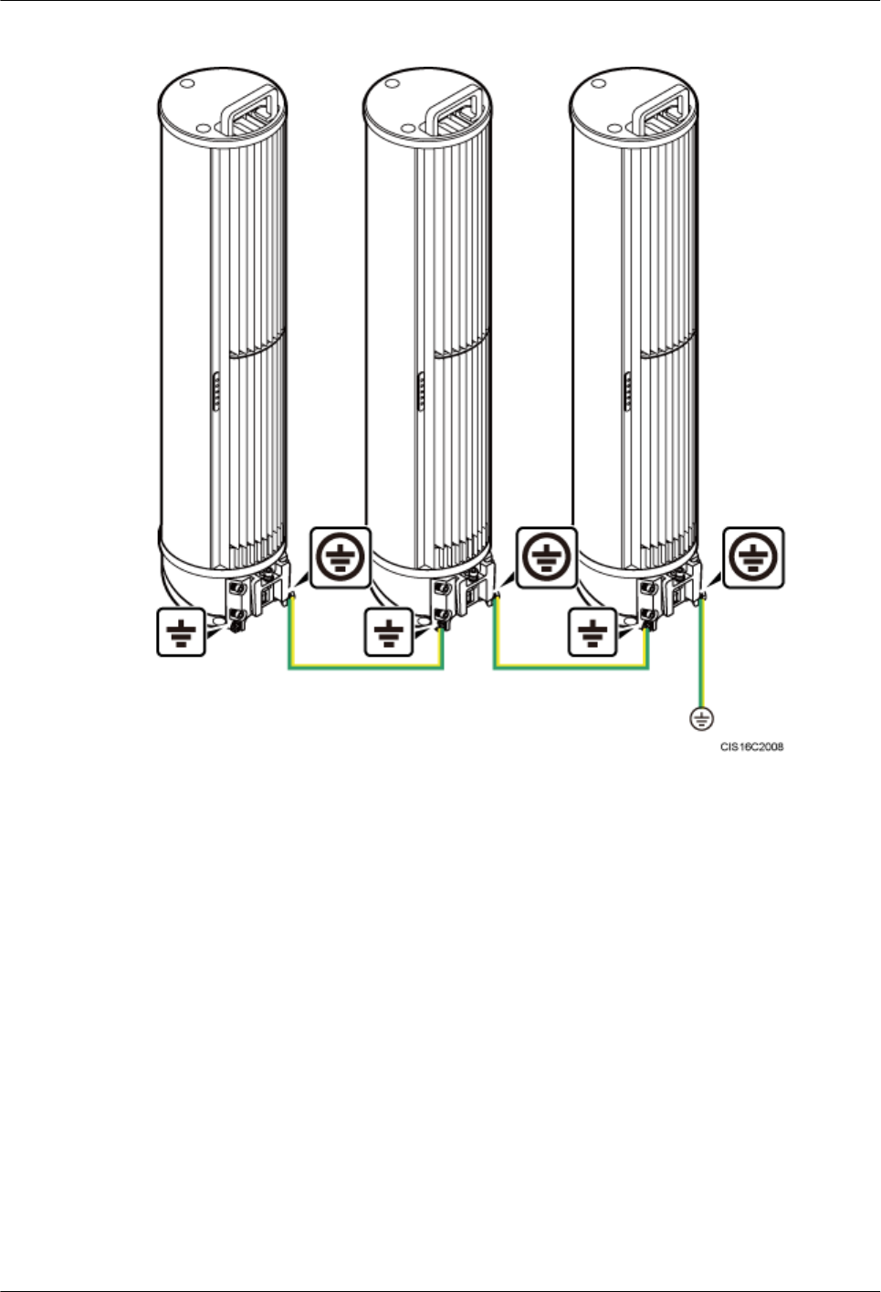
Figure 10-13 Installing equipotential cables when multiple AAUs are installed on a pole
Step 4 Lay out the cables according to the instructions in Cabling Requirements, and use cable ties to
bind them.
Step 5 Label the installed cables according to the instructions in Attaching a Sign Plate Label.
----End
10.3 Installing an AAU Power Cable
This section describes the process and precautions for installing an AAU power cable.
Prerequisites
The AAU maintenance cavity has been opened.
Context
The following table describes AAU power cables used in different scenarios.
AAU3940
Installation Guide 10 Installing AAU Cables
Issue 01 (2015-01-15) Huawei Proprietary and Confidential
Copyright © Huawei Technologies Co., Ltd.
67
Table 10-2 AAU power cables
Scenari
o
One End The Other End
Connector Install
ation
Positi
on
Connector Installation Position
No
ODM is
configur
ed.
Tool-less
female
connector
(pressfit type)
POWE
R-IN
port on
an
AAU
Depending
on the power
equipment
Power equipment
An
ODM is
configur
ed.
Tool-less
female
connector
(pressfit type)
POWE
R-IN
port on
an
AAU
Cord end
terminal
L, N, and PE terminals near the
OUTPUT silkscreen on the ODM
CAUTION
AAU power cables must be routed and protected according to the local laws and regulations,
industry standards, and operators' standards.
CAUTION
When installing an AAU power cable for a running base station, connect the cable to the AAU
before connecting it to the power system. An incorrect sequence or reverse connection of the
power cable will cause damage to the AAU or injuries to the human body.
Procedure
lProtecting an AAU power cable using a tube
1. Cut the cable to the length suitable for the actual cable route.
2. Before adding connectors to the cable, put the cable through a PVC corrugated pipe
or metal tube. The length of the PVC corrugated pipe or metal tube depends on the
length of the cable. Waterproof the PVC corrugated pipe or metal tube, and ground
both ends of the metal tube.
lPreparing an AAU power cable
1. Add a tool-less female connector (pressfit type) to the AAU's AC power cable. For
details, see 16.2 Adding a Tool-Less Female Connector (Pressfit Type) to an AAU
Power Cable on the AAU Side.
2. Add the corresponding connector to the end of the AAU power cable connected to
power equipment according to the type of the port on the power equipment.
AAU3940
Installation Guide 10 Installing AAU Cables
Issue 01 (2015-01-15) Huawei Proprietary and Confidential
Copyright © Huawei Technologies Co., Ltd.
68
–If no ODM is configured, add the corresponding connector to the power cable
according to the type of the port on the power equipment.
–If an ODM is configured, add cord end terminals to the end of the power cable
connected to the ODM according to the instructions in Assembling the Cord End
Terminal and the Power Cable.
lConnecting an AAU power cable to an AAU
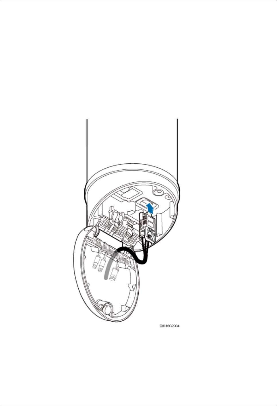
1. Route an AAU power cable into the maintenance cavity through the rear of the
maintenance cavity.
2. Connect one end of the AAU power cable with a tool-less female connector (pressfit
type) to the power port on the AAU, as shown in the following figure.
Figure 10-14 Connecting an AAU power cable to an AAU
3. Use a clip to secure the power cable, as shown in the following figure.
a. Use an M4 screwdriver to loosen two screws in sequence to open the power cable
clip.
b. Put the power cable through the clip and waterproof trough, and close the clip.
AAU3940
Installation Guide 10 Installing AAU Cables
Issue 01 (2015-01-15) Huawei Proprietary and Confidential
Copyright © Huawei Technologies Co., Ltd.
69
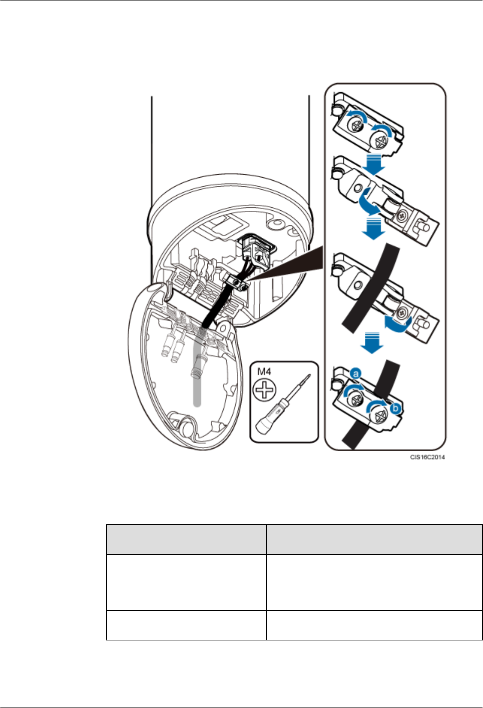
c. Use an M4 torque screwdriver to tighten the screws indicated by a and b in the
following figure to 1.4 N·m (12.39 lbf·in.) in sequence.
Figure 10-15 Securing a power cable
lConnecting an AAU power cable to power equipment
If... Then...
No ODM is configured Connect the other end of the AAU power cable to
the corresponding port on external power
equipment.
An ODM is configured Perform the following operations.
1. Use a screwdriver to pierce silica gel in the cable holes near the OUTPUT silkscreen
on the ODM, as shown by illustration a in the following figure. Do not pierce silica
AAU3940
Installation Guide 10 Installing AAU Cables
Issue 01 (2015-01-15) Huawei Proprietary and Confidential
Copyright © Huawei Technologies Co., Ltd.
70
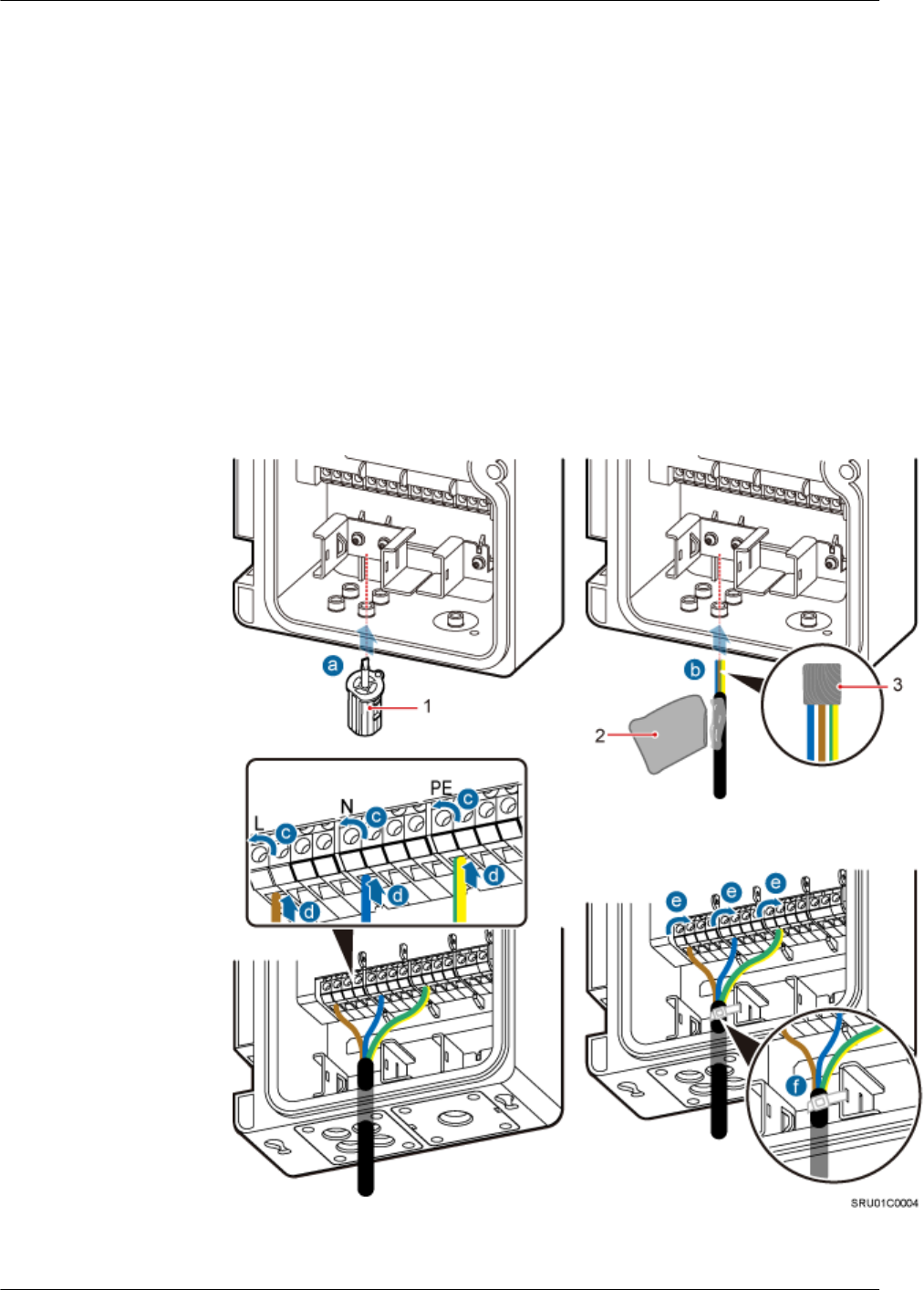
gel in the cable holes through which no cables are routed because silica gel is required
to provide the waterproof function.
2. Use insulation tape to wrap cord end terminals of the power cable to prevent sharp
edges of the cord end terminal from damaging silica gel.
3. Apply petroleum jelly to the power cable, and then route the power cable through a
cable hole.
4. Use the screwdriver delivered with the ODM to loosen screws on the terminals to
which the power cable is to be connected, and connect the terminals on the power
cable to the corresponding terminals, as shown by illustrations c and d in the following
figure.
5. Tighten the screws on the terminals of the power cable, as shown by illustration e in
the following figure.
6. Securely bind the power cable to the binding bracket, as shown by illustration f in the
following figure.
Figure 10-16 Connecting an AAU power cable to an ODM
(1) Screwdriver delivered with the ODM (2) Petroleum jelly (3) Insulation tape
AAU3940
Installation Guide 10 Installing AAU Cables
Issue 01 (2015-01-15) Huawei Proprietary and Confidential
Copyright © Huawei Technologies Co., Ltd.
71
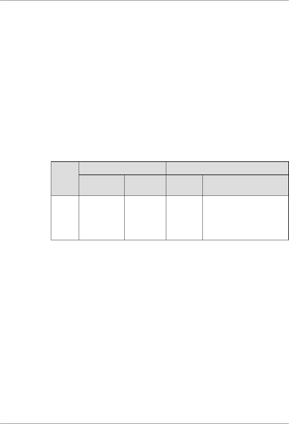
lLay out the cables according to the instructions in Cabling Requirements, and use cable
ties to bind them.
lLabel the installed cables according to the instructions in Attaching a Cable-Tying Label.
----End
10.4 Installing an ODM Power Cable
This section describes the process and precautions for installing an ODM power cable when an
ODM is configured.
Context
The following table describes the ODM power cable connections.
Table 10-3 ODM power cable connections
Cable One End The Other End
Connector Installation
Position
Connector Installation Position
ODM
power
cable
Cord end
terminal
L, N, and PE
terminals near
the INPUT
silkscreen on
the ODM
Depending
on the
power
equipment
External power equipment
Procedure
Step 1 Prepare an ODM power cable.
lAdd a cord end terminal to the end of the power cable connected to the ODM side according
to the instructions in Assembling the Cord End Terminal and the Power Cable.
lAdd a connector to the other end of the ODM power cable connected to power equipment
according to the type of the port on the power equipment.
Step 2 Loosen the M4 captive screw from the ODM case and open the ODM case.
Step 3 Use a screwdriver to pierce silica gel in the cable holes near the INPUT silkscreen on the ODM.
Step 4 Use insulation tape to wrap cord end terminals of the power cable to prevent sharp edges of the
cord end terminal from damaging silica gel.
Step 5 Apply petroleum jelly to the power cable, and then route the power cable through a cable hole.
Step 6 Connect one end of the power cable to the L, N, and PE terminals near the INPUT silkscreen,
and use a torque screwdriver to tighten the screws to 0.8 N·m (7.08 lbf·in.), as shown in the
following figure.
AAU3940
Installation Guide 10 Installing AAU Cables
Issue 01 (2015-01-15) Huawei Proprietary and Confidential
Copyright © Huawei Technologies Co., Ltd.
72
Step 7 Securely bind the power cable to the binding bracket, as shown in the following figure.
Figure 10-17 Installing an ODM power cable
Step 8 Connect the other end of the ODM power cable to the external power equipment.
Step 9 Lay out the cables according to the instructions in Cabling Requirements, and use cable ties to
bind them.
Step 10 Label the installed cables according to the instructions in Attaching a Cable-Tying Label.
----End
10.5 Installing a Trunk CPRI Fiber Optic Cable Between an
ODM and a BBU
This section describes the procedure for installing a trunk CPRI fiber optic cable between an
ODM and a BBU when an ODM is configured.
Prerequisites
A fiber fusion splicer is available.
Context
A CPRI fiber optic cable to be installed is shown by illustration 3 in the following figure.
AAU3940
Installation Guide 10 Installing AAU Cables
Issue 01 (2015-01-15) Huawei Proprietary and Confidential
Copyright © Huawei Technologies Co., Ltd.
73
Figure 10-18 Installing CPRI fiber optic cables
(1) CPRI fiber optic cable between
an AAU and a BBU
(2) CPRI fiber optic cable between
an AAU and an ODM
(3) CPRI fiber optic cable between
an ODM and a BBU
NOTE
lThe single-mode optical module is labeled as SM and the multimode optical module is labeled as MM.
lThe puller of a single-mode optical module is blue and the puller of a multimode optical module is
black or gray.
lThe following figure shows the label on an optical module.
Figure 10-19 Label on an optical module
(1) Maximum rate (2) Wavelength (3) Transmission mode
NOTICE
The performance of an optical module may deteriorate if it is exposed to the air for more than
20 minutes. Therefore, insert a fiber optic cable into an unpacked optical module within 20
minutes.
AAU3940
Installation Guide 10 Installing AAU Cables
Issue 01 (2015-01-15) Huawei Proprietary and Confidential
Copyright © Huawei Technologies Co., Ltd.
74
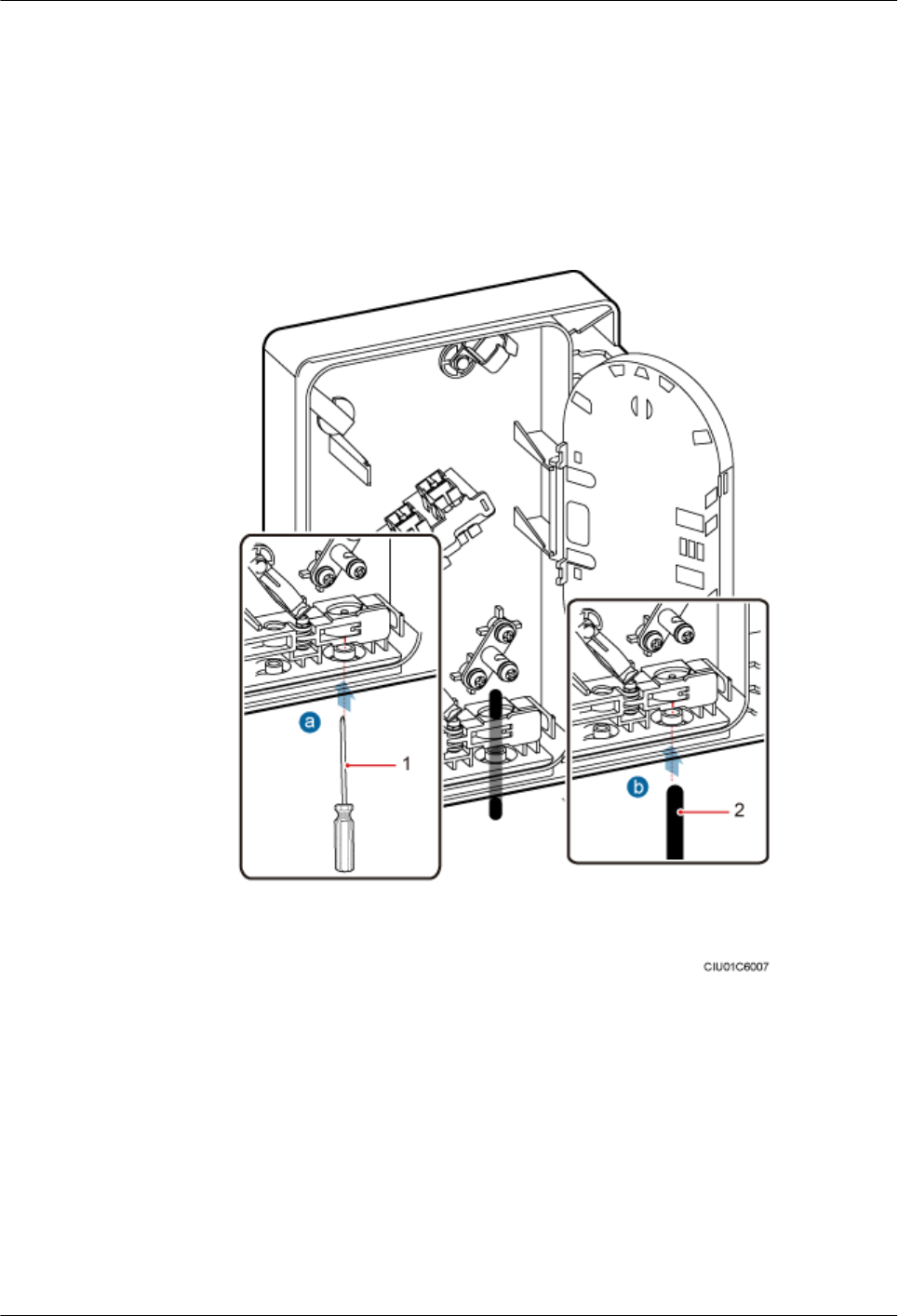
Procedure
lStripping a trunk fiber optic cable and pigtails
1. Use a screwdriver to pierce silica gel in the cable hole on the ODM for the trunk fiber
optic cable, as shown by illustration a in the following figure.
2. Route a trunk fiber optic cable through the cable hole, as shown by illustration b in
the following figure.
Figure 10-20 Routing a trunk fiber optic cable through a cable hole
(1) Screwdriver (2) Trunk fiber optic cable
3. Strip a specified length of sheath off the trunk fiber optic cable, as shown in the
following figure.
AAU3940
Installation Guide 10 Installing AAU Cables
Issue 01 (2015-01-15) Huawei Proprietary and Confidential
Copyright © Huawei Technologies Co., Ltd.
75
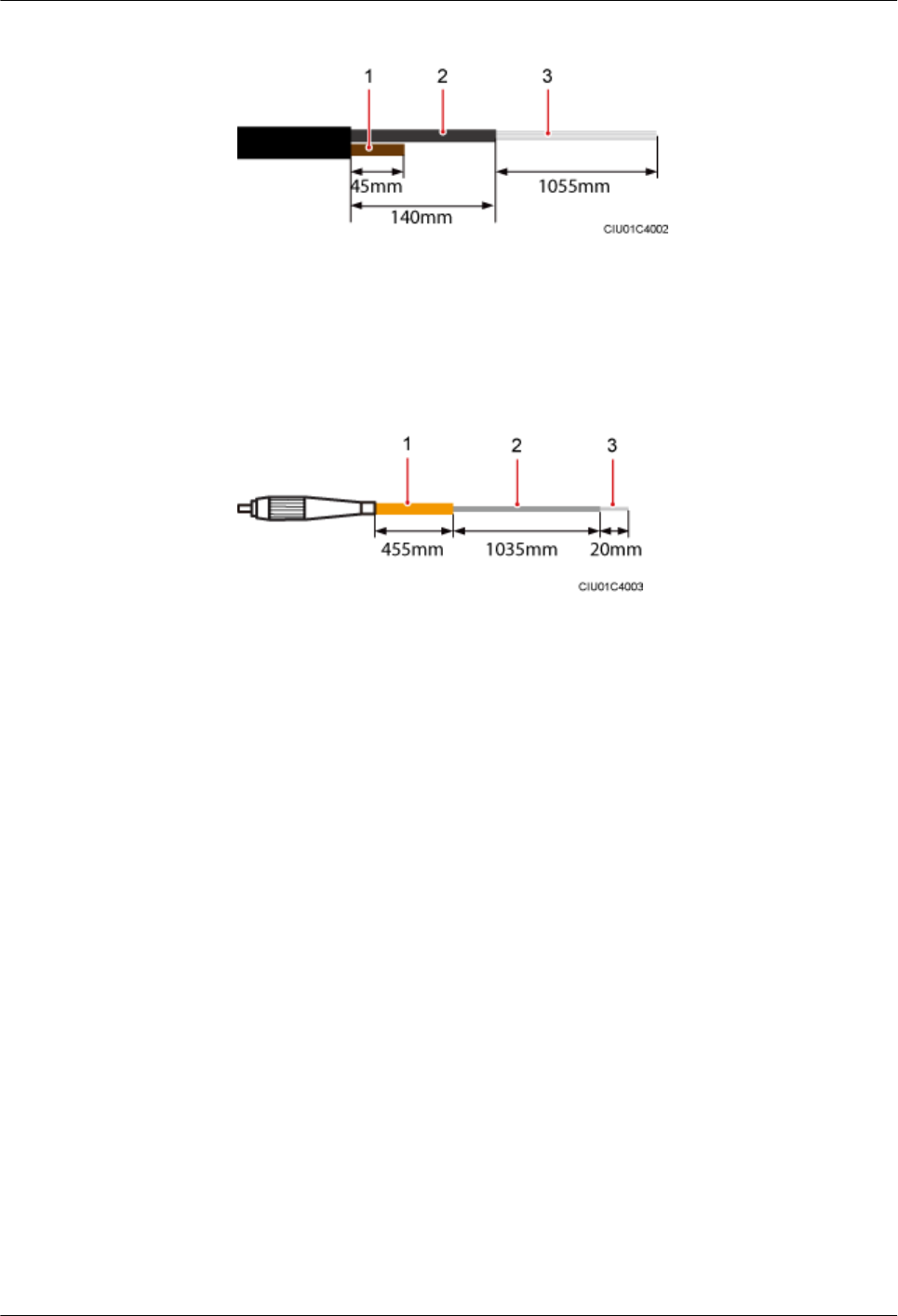
Figure 10-21 Stripping a specified length of sheath off a trunk fiber optic cable
(1) Strength member (2) Core wire (3) Bare fiber
4. Strip a specified length of sheath off the pigtail, as shown in the following figure.
Figure 10-22 Stripping a specified length of sheath off a pigtail
(1) Sheath (2) Core wire (3) Bare fiber
lInstalling a trunk fiber optic cable
1. Route the strength member through the hanger, bend the strength member, and tighten
the screw on the hanger to 1.2 N·m (10.62 lbf·in.), as shown by illustration a in the
following figure.
2. Use a finger to press the clip until it snaps into place, as shown by illustration b in the
following figure.
3. Route the core wire of the trunk fiber optic cable through the cable hole in the splicing
tray, and use a cable tie to fasten the core wire, as shown by illustration c in the
following figure.
AAU3940
Installation Guide 10 Installing AAU Cables
Issue 01 (2015-01-15) Huawei Proprietary and Confidential
Copyright © Huawei Technologies Co., Ltd.
76
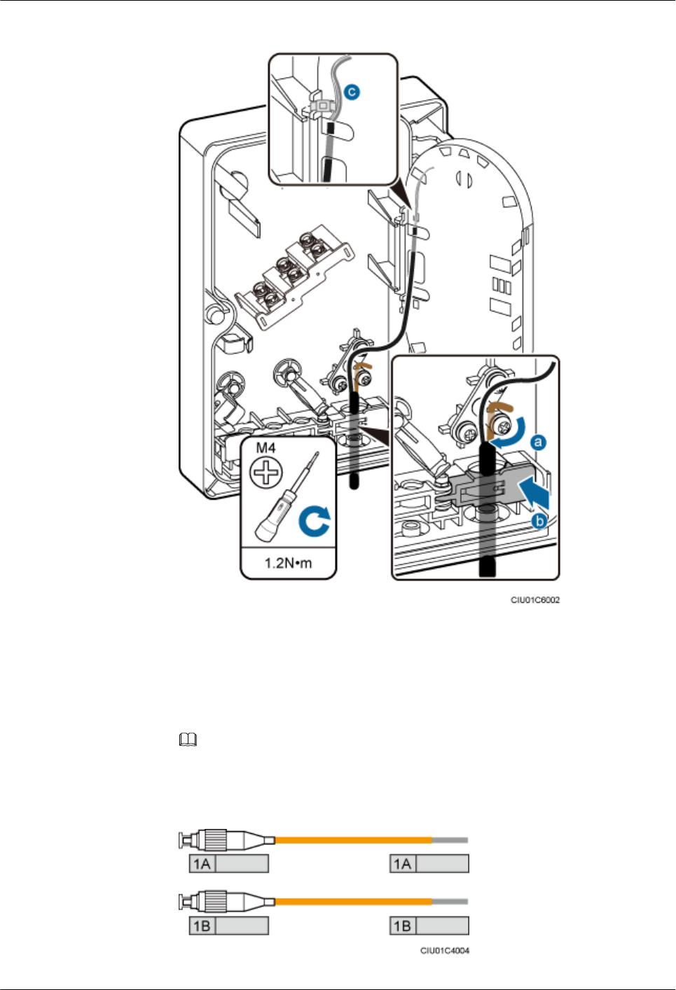
Figure 10-23 Installing a trunk fiber optic cable
lInstalling a pigtail
1. Attach labels delivered with the splicing tray in the ODM to both ends of the pigtails
to be installed.
NOTE
The following figure shows the first group of labeled pigtails.
Figure 10-24 First group of labeled pigtails
AAU3940
Installation Guide 10 Installing AAU Cables
Issue 01 (2015-01-15) Huawei Proprietary and Confidential
Copyright © Huawei Technologies Co., Ltd.
77
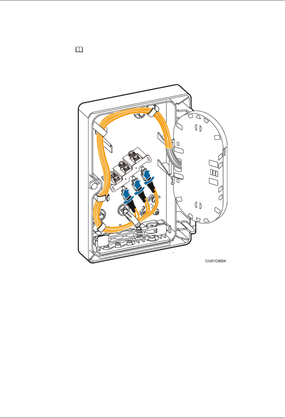
2. Insert the end of the pigtails with FC connectors to the adapter delivered with the
ODM, coil the fiber optic cable clockwise, and route the fiber optic cable through the
cable hole in the splicing tray, as shown in the following figure.
NOTE
This section uses FC connectors as examples. SC or LC connectors can be added to pigtails.
Figure 10-25 Connecting pigtails and coiling the fiber optic cable
lSplicing fiber and coiling the fiber optic cable
1. Put the heat shrink tubing onto the bare fiber at one end of the trunk fiber optic cable.
2. Use cloth dipped in detergent to clean the ends of the trunk fiber optic cable and
pigtails, and ensure that the spliced area is cleaned.
3. Use a fiber fusion splicer to splice the trunk fiber optic cable and pigtails.
4. Move the heat shrink tubing to the fiber splice point so that the tubing shrinks, and
install a protective cover to the trough to protect the fiber splice point.
5. Coil the trunk fiber optic cable counterclockwise and the pigtails clockwise in the
splicing tray, as shown in the following figure.
AAU3940
Installation Guide 10 Installing AAU Cables
Issue 01 (2015-01-15) Huawei Proprietary and Confidential
Copyright © Huawei Technologies Co., Ltd.
78
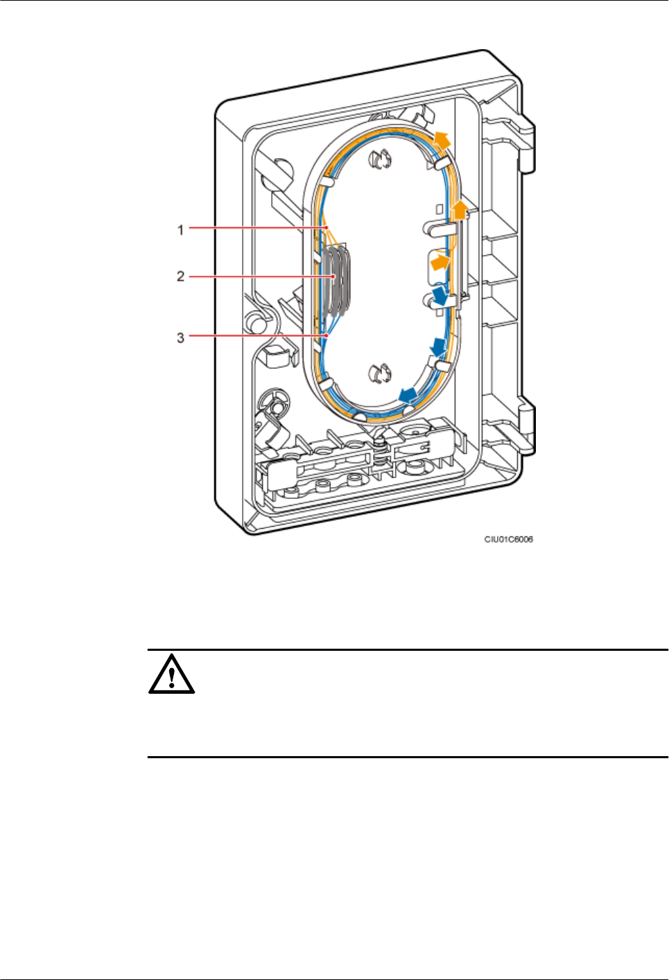
Figure 10-26 Coiling the spliced fiber optic cable
(1) Trunk fiber optic cable (2) Heat shrink tubing (3) Pigtail
NOTICE
To open the ODM case for maintenance, a minimum of 40 mm (1.57 in.) fiber optic cable
is reserved outside the ODM case, as shown in the following figure.
AAU3940
Installation Guide 10 Installing AAU Cables
Issue 01 (2015-01-15) Huawei Proprietary and Confidential
Copyright © Huawei Technologies Co., Ltd.
79
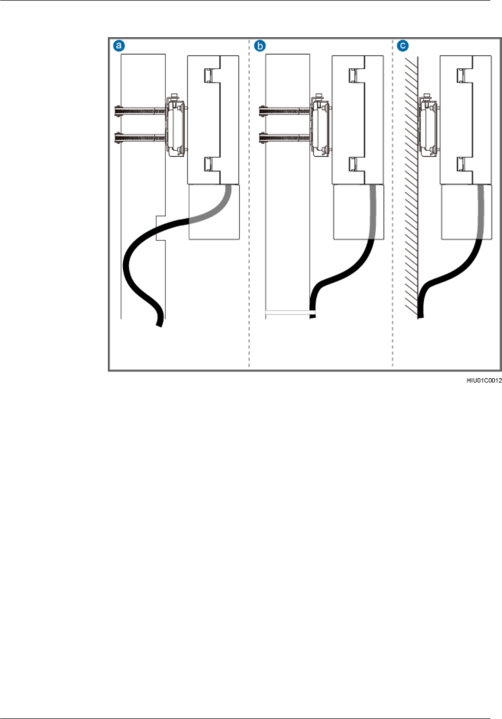
Figure 10-27 Reserving slack of a CPRI fiber optic cable
a: Scenario in which a pole is used
(routing a cable along the inner
side of the pole)
b: Scenario in which a pole is used
(routing a cable along the outer
side of the pole)
c: Scenario in which a wall is used
lLay out the cables according to the instructions in Cabling Requirements, and use cable
ties to bind them.
lLabel the installed cables according to the instructions in Attaching an L-Shaped Label.
----End
10.6 Installing a CPRI Fiber Optic Cable Between an AAU
and a BBU or Between an AAU and an ODM
If no ODM is configured, a CPRI fiber optic cable is directly connected to a BBU. If an ODM
is configured, a CPRI fiber optic cable is connected to the ODM.
Context
A CPRI fiber optic cable to be installed is shown by illustration 1 or 2 in the following figure.
AAU3940
Installation Guide 10 Installing AAU Cables
Issue 01 (2015-01-15) Huawei Proprietary and Confidential
Copyright © Huawei Technologies Co., Ltd.
80
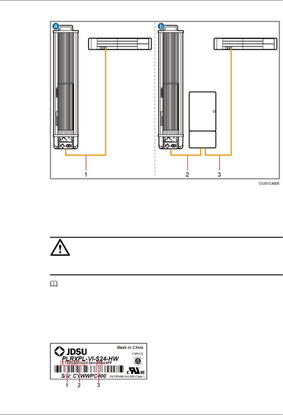
Figure 10-28 Installing CPRI fiber optic cables
(1) CPRI fiber optic cable between
an AAU and a BBU
(2) CPRI fiber optic cable between
an AAU and an ODM
(3) CPRI fiber optic cable between
an ODM and a BBU
NOTICE
The optical modules to be installed must match the rates of their corresponding CPRI ports.
NOTE
lThe single-mode optical module is labeled as SM and the multimode optical module is labeled as MM.
lThe puller of a single-mode optical module is blue and the puller of a multimode optical module is
black or gray.
lThe following figure shows the label on an optical module.
Figure 10-29 Label on an optical module
(1) Maximum rate (2) Wavelength (3) Transmission mode
AAU3940
Installation Guide 10 Installing AAU Cables
Issue 01 (2015-01-15) Huawei Proprietary and Confidential
Copyright © Huawei Technologies Co., Ltd.
81
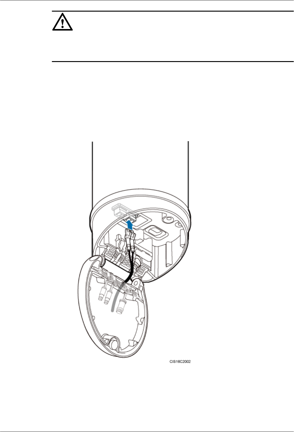
NOTICE
The performance of an optical module may deteriorate if it is exposed to the air for more than
20 minutes. Therefore, insert a fiber optic cable into an unpacked optical module within 20
minutes.
Procedure
lConnecting a CPRI fiber optic cable to an AAU
1. Route a CPRI fiber optic cable into the maintenance cavity through the rear of the
maintenance cavity.
2. Insert the optical connector into the optical module, as shown in the following figure.
Figure 10-30 Connecting a CPRI fiber optic cable to an AAU (a)
3. Press the fiber concentrator into the waterproof trough, as shown in the following
figure.
AAU3940
Installation Guide 10 Installing AAU Cables
Issue 01 (2015-01-15) Huawei Proprietary and Confidential
Copyright © Huawei Technologies Co., Ltd.
82
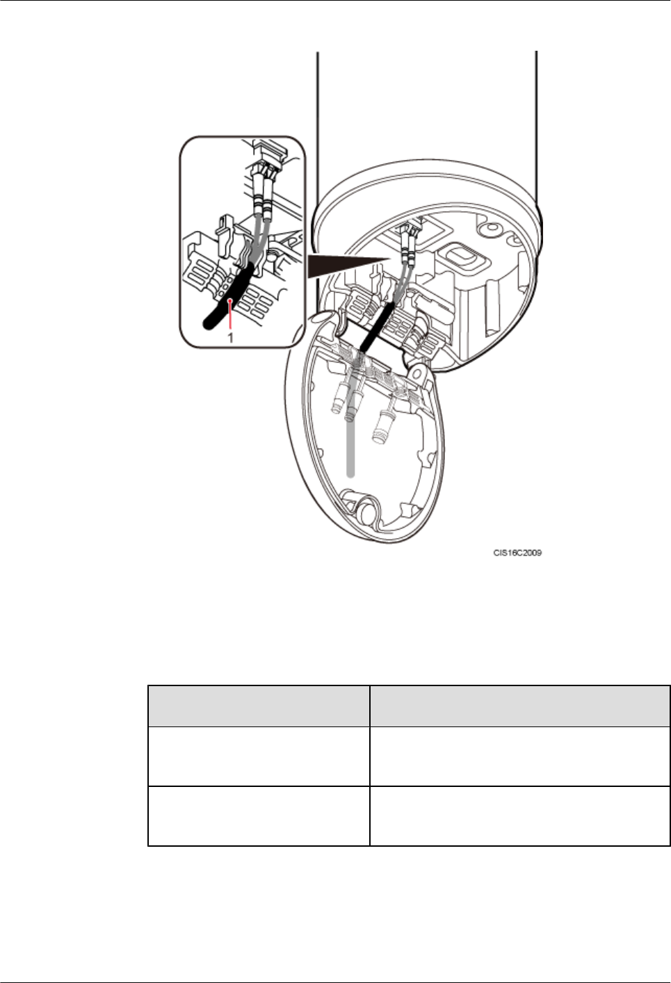
Figure 10-31 Connecting a CPRI fiber optic cable to an AAU (b)
(1) Fiber concentrator
lInstalling a CPRI fiber optic cable between a BBU and an ODM
If... Then...
The CPRI fiber optic cable is to be
connected the BBU
Insert the other end of the fiber optic cable into the
optical module on the BBU side.
The CPRI fiber optic cable is to be
connected to the ODM
Perform the following operations.
1. Use a screwdriver to pierce silica gel in the cable hole on the ODM for the output fiber
optic cable.
2. Route the other end of the fiber optic cable with an FC connector through the cable
hole, coil the fiber optic cable counterclockwise, and connect the fiber optic cable to
AAU3940
Installation Guide 10 Installing AAU Cables
Issue 01 (2015-01-15) Huawei Proprietary and Confidential
Copyright © Huawei Technologies Co., Ltd.
83
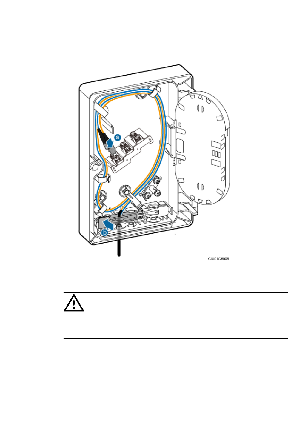
the corresponding port on the fiber adapter, as shown by illustration a in the following
figure.
3. Use a finger to press the clip until it snaps into place, as shown by illustration b in the
following figure.
Figure 10-32 Connecting a CPRI fiber optic cable to an ODM
NOTICE
To open the ODM case for maintenance, a minimum of 40 mm (1.57 in.) fiber optic cable
is reserved outside the ODM case, as shown in the following figure.
AAU3940
Installation Guide 10 Installing AAU Cables
Issue 01 (2015-01-15) Huawei Proprietary and Confidential
Copyright © Huawei Technologies Co., Ltd.
84
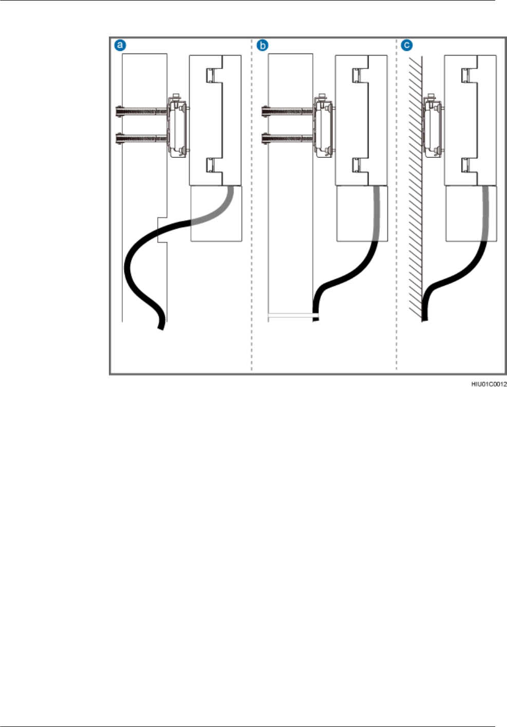
Figure 10-33 Reserving slack of a CPRI fiber optic cable
a: Scenario in which a pole is used
(routing a cable along the inner
side of the pole)
b: Scenario in which a pole is used
(routing a cable along the outer
side of the pole)
c: Scenario in which a wall is used
lLay out the cables according to the instructions in Cabling Requirements, and use cable
ties to bind them.
lLabel the installed cables according to the instructions in Attaching an L-Shaped Label.
----End
Follow-up Procedure
After all cables for the ODM are installed, close the ODM case and tighten the M4 screw on the
cover.
AAU3940
Installation Guide 10 Installing AAU Cables
Issue 01 (2015-01-15) Huawei Proprietary and Confidential
Copyright © Huawei Technologies Co., Ltd.
85
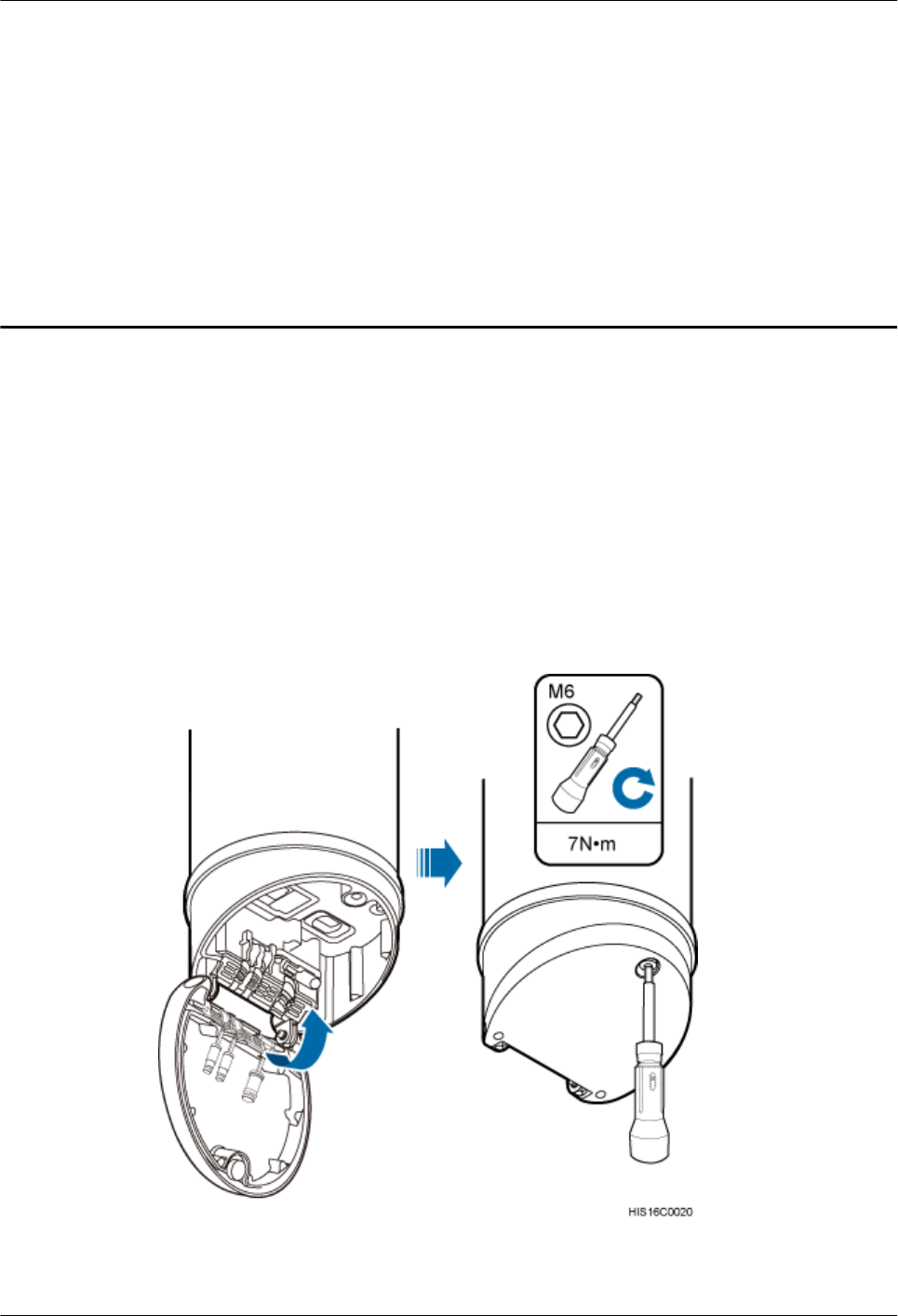
11 Closing a Maintenance Cavity
After all installation procedures are complete, you need to close the AAU maintenance cavity.
Procedure
Step 1 Use waterproof blocks to seal vacant waterproof troughs in the maintenance cavity.
Step 2 Use an M6 inner hexagon torque screwdriver to tighten the screw on the maintenance cavity, as
shown in the following figure.
Figure 11-1 Closing a maintenance cavity
----End
AAU3940
Installation Guide 11 Closing a Maintenance Cavity
Issue 01 (2015-01-15) Huawei Proprietary and Confidential
Copyright © Huawei Technologies Co., Ltd.
86
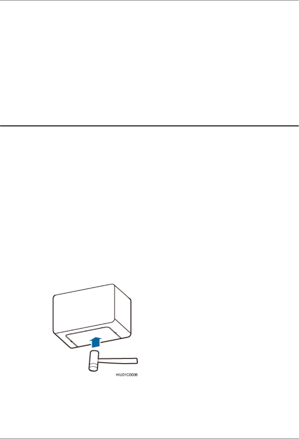
12 (Optional) Installing a Cord Cover for an
ODM
This section describes a procedure for installing a cord cover for an ODM after all cables are
installed.
Prerequisites
lAn ODM has been installed.
lAll cables for the ODM have been installed.
Procedure
Step 1 Optional: When an ODM is installed on a wall or ODM cables are routed along the outer side
of a pole, remove the part from the bottom of a cord cover, as shown in the following figure. If
cables are routed along the inner side of a pole, skip this step.
Figure 12-1 Removing a part
Step 2 Lift the cord cover so that the two round dowels on the top of the cord cover are inserted into
the holes on the bottom of the ODM, and push the cord cover upwards, as shown in the following
figure.
AAU3940
Installation Guide 12 (Optional) Installing a Cord Cover for an ODM
Issue 01 (2015-01-15) Huawei Proprietary and Confidential
Copyright © Huawei Technologies Co., Ltd.
87
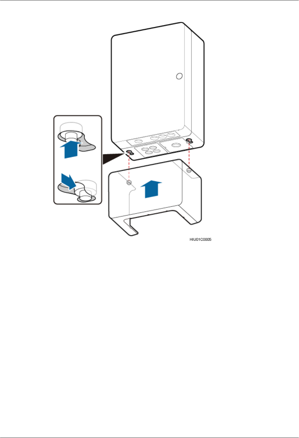
Figure 12-2 Installing a cord cover
----End
AAU3940
Installation Guide 12 (Optional) Installing a Cord Cover for an ODM
Issue 01 (2015-01-15) Huawei Proprietary and Confidential
Copyright © Huawei Technologies Co., Ltd.
88

13 Adjusting the Horizontal Azimuth of an
Antenna
This section describes the procedure for adjusting the horizontal azimuth of an antenna based
on coverage requirements after all cables are installed.
Context
The normal line of an antenna is located on the front of the antenna, as shown in the following
figure. Before adjusting the horizontal azimuth of an antenna, determine the direction towards
which the antenna faces according to the normal line.
AAU3940
Installation Guide 13 Adjusting the Horizontal Azimuth of an Antenna
Issue 01 (2015-01-15) Huawei Proprietary and Confidential
Copyright © Huawei Technologies Co., Ltd.
89
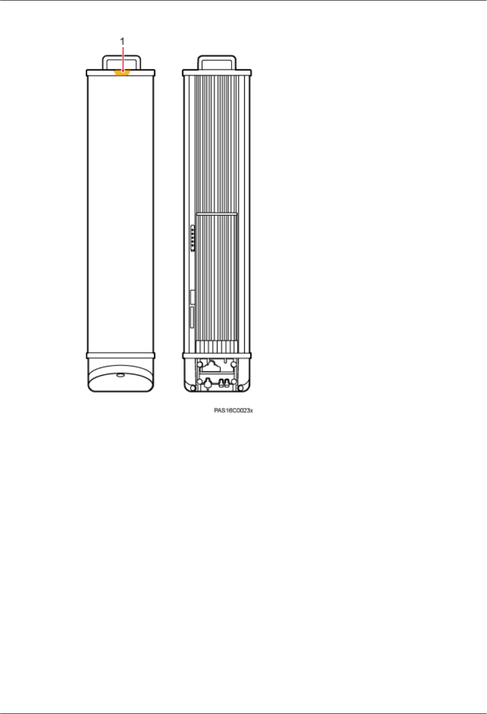
Figure 13-1 Normal line of an antenna
(1) Normal line of an antenna
Procedure
lAdjusting the horizontal azimuth of an antenna installed on a pole or wall
1. Loosen the screws on the angle adjusting component, and rotate the angle adjusting
component based on the coverage requirements, as shown in the following figure.
AAU3940
Installation Guide 13 Adjusting the Horizontal Azimuth of an Antenna
Issue 01 (2015-01-15) Huawei Proprietary and Confidential
Copyright © Huawei Technologies Co., Ltd.
90
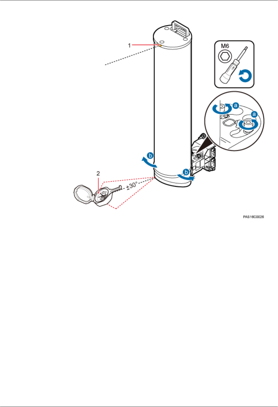
Figure 13-2 Adjusting the horizontal azimuth of an antenna (1)
(1) Normal line of an antenna (2) Geologic compass
2. Tighten the screws on the angle adjusting component to 6 N·m (53.1 lbf·in.).
lAdjusting the horizontal azimuth of an antenna installed on the top of a pole
1. Lift the landscaping cover until it is stuck above the elastomer.
2. Loosen the screws on the mounting bracket, and rotate the mounting bracket based
on the coverage requirements, as shown in the following figure.
AAU3940
Installation Guide 13 Adjusting the Horizontal Azimuth of an Antenna
Issue 01 (2015-01-15) Huawei Proprietary and Confidential
Copyright © Huawei Technologies Co., Ltd.
91
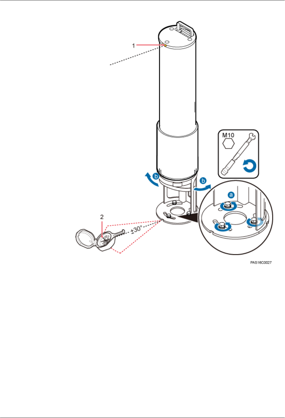
Figure 13-3 Adjusting the horizontal azimuth of an antenna (2)
(1) Normal line of an antenna (2) Geologic compass
3. Use a torque wrench to tighten the screws on the mounting bracket to 28 N·m (247.8
lbf·in.).
----End
AAU3940
Installation Guide 13 Adjusting the Horizontal Azimuth of an Antenna
Issue 01 (2015-01-15) Huawei Proprietary and Confidential
Copyright © Huawei Technologies Co., Ltd.
92
14 Installation Checklist
This section describes the checklist for AAU hardware installation.
The following table describes the checklist for AAU hardware installation.
Table 14-1 Hardware installation checklist
No. Item
1The installation position of each device strictly complies with the engineering
design and meets clearance requirements. Sufficient space is reserved for
equipment maintenance.
2 An AAU is securely attached to an attachment plate, and the attachment plate is
securely attached to mounting kits.
3 A fiber concentrator is pressed into the waterproof trough in the maintenance cavity.
4 The screw on the cover plate for the maintenance cavity at the bottom of the AAU
is tightened to the torque recommended in this document.
5 Waterproof blocks are securely installed in vacant cable troughs of the maintenance
cavity, and the cover plate for the cabling cavity is securely installed.
6 There are no connectors or joints on each power cable or PGND cable.
7 The terminals at both ends of each power cable or PGND cable are securely
crimped.
8 None of power cables and PGND cables can be short-circuited or reversely
connected. In addition, these cables are not damaged or broken.
9 Power cables and PGND cables are separately bound.
10 The building surge protection ground and the antenna surge protection ground are
separately performed.
11 The connectors of each signal cable are intact and securely connected.
12 Mounting kits are securely installed.
AAU3940
Installation Guide 14 Installation Checklist
Issue 01 (2015-01-15) Huawei Proprietary and Confidential
Copyright © Huawei Technologies Co., Ltd.
93

No. Item
13 Labels are correct, legible, and complete at both ends of each cable, such as feeders
and jumpers.
AAU3940
Installation Guide 14 Installation Checklist
Issue 01 (2015-01-15) Huawei Proprietary and Confidential
Copyright © Huawei Technologies Co., Ltd.
94
15 Powering on an AAU
This section describes the procedure and precautions for powering on an AAU.
Context
DANGER
lBefore powering on a base station, check that the positive and negative wires of all power
cables are correctly connected. Any incorrect power cable connection may cause damage to
equipment or unexpected injuries of human body.
lExercise caution when performing a power-on check, which involves high voltage
operations. Direct contact with the input voltage or indirect contact with the input voltage
using a damp object may be fatal.
NOTICE
lAfter unpacking the RU, you must power on it within 24 hours. If you power off the RU for
maintenance, you must restore power to the RU within 24 hours.
lKeep a minimum of 7.35 m (24.11 ft) away from the front of the AAU after the RU is powered
on and the AAU starts working.
Process
The following figure shows the process of powering on an AAU.
AAU3940
Installation Guide 15 Powering on an AAU
Issue 01 (2015-01-15) Huawei Proprietary and Confidential
Copyright © Huawei Technologies Co., Ltd.
95
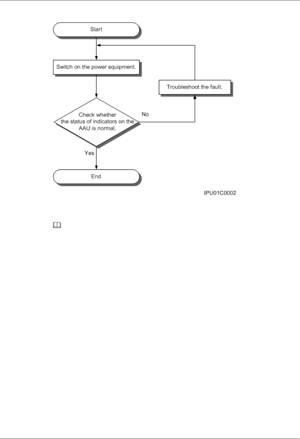
Figure 15-1 Process of powering on an AAU
NOTE
lThe normal input voltage of an AAU is 220 V AC and should range from 200 V AC to 240 V AC.
lWhen an AAU is working properly, the RUN indicator is blinking (on for 1s and off for 1s), and the ALM
indicator is steady off. For details about indicators, see AAU3940 Hardware Description.
AAU3940
Installation Guide 15 Powering on an AAU
Issue 01 (2015-01-15) Huawei Proprietary and Confidential
Copyright © Huawei Technologies Co., Ltd.
96

16 Appendix
About This Chapter
This chapter describes auxiliary operations during an AAU installation process.
16.1 Assembling the OT Terminal and the Power Cable
There are two types of OT terminal: one-hole OT terminal and two-hole OT terminal. This
section describes the procedure for adding an OT terminal to a power cable by taking a one-hole
OT terminal as an example.
16.2 Adding a Tool-Less Female Connector (Pressfit Type) to an AAU Power Cable on the AAU
Side
This section describes the procedure for adding a tool-less female connector (pressfit type) to
an AAU power cable on the AAU side.
AAU3940
Installation Guide 16 Appendix
Issue 01 (2015-01-15) Huawei Proprietary and Confidential
Copyright © Huawei Technologies Co., Ltd.
97
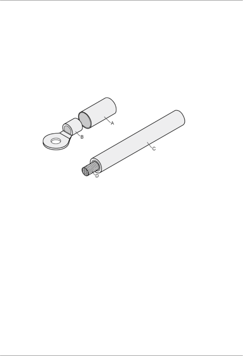
16.1 Assembling the OT Terminal and the Power Cable
There are two types of OT terminal: one-hole OT terminal and two-hole OT terminal. This
section describes the procedure for adding an OT terminal to a power cable by taking a one-hole
OT terminal as an example.
Context
Figure 16-1 shows a one-hole OT terminal and materials related to a power cable.
Figure 16-1 one-hole OT terminal and materials related to a power cable
A heat shrink tubing B. one-hole OT terminal
with a bare crimping
terminal
C. Insulation layer of a power
cable
D. Conductor of a power
cable
Figure 16-2 shows a two-hole OT terminal and materials related to a power cable.
AAU3940
Installation Guide 16 Appendix
Issue 01 (2015-01-15) Huawei Proprietary and Confidential
Copyright © Huawei Technologies Co., Ltd.
98
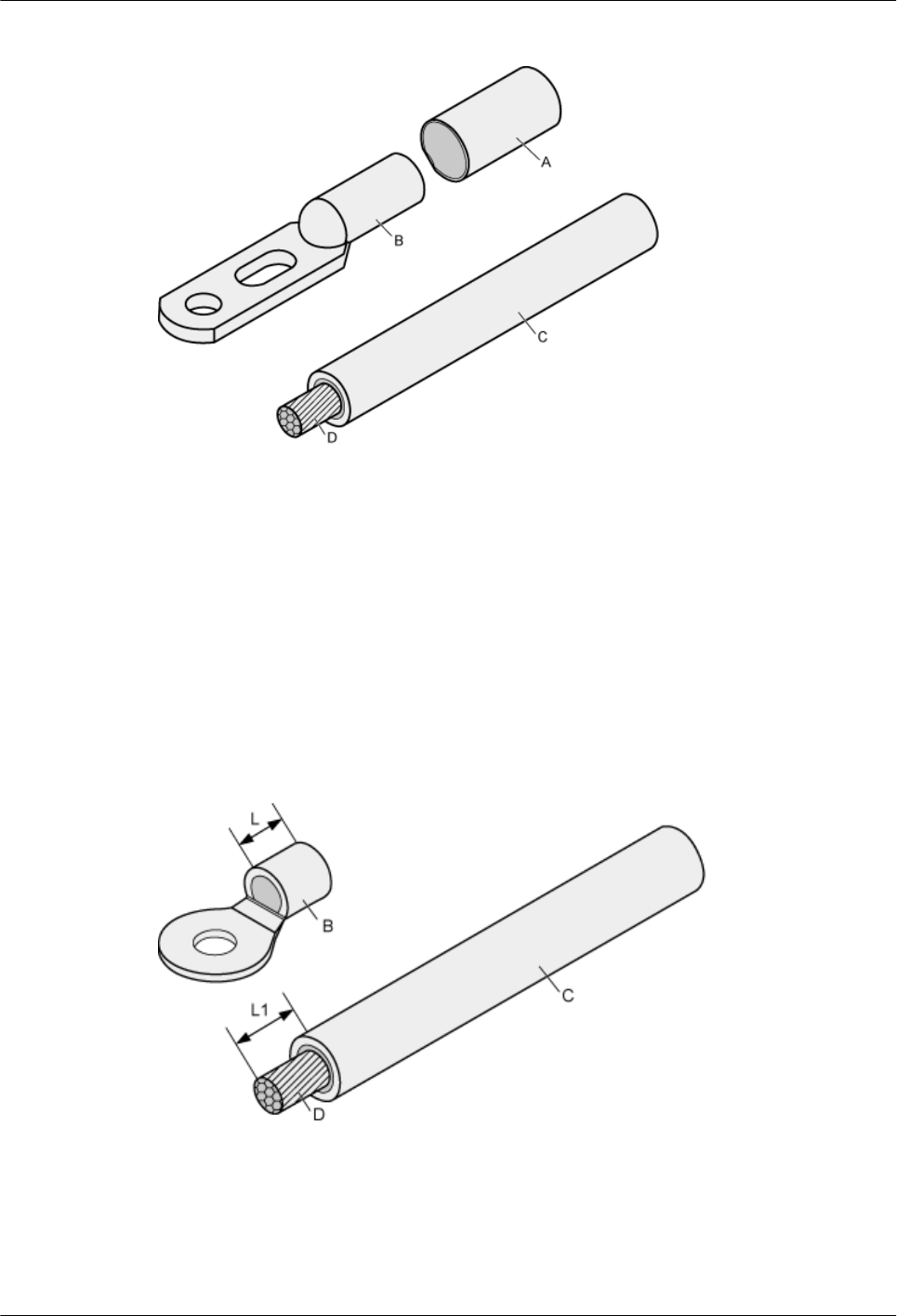
Figure 16-2 two-hole OT terminal and materials related to a power cable
A heat shrink tubing B. two-hole OT terminal
with a bare crimping
terminal
C. Insulation layer of a power
cable
D. Conductor of a power
cable
Procedure
Step 1 Based on the cross-sectional area of the cable conductor, strip a part of the insulation layer. The
L1-long conductor is exposed, as shown in Figure 16-3. The recommended values of L1 are
listed in Table 16-1.
Figure 16-3 Stripping a power cable (OT terminal)
AAU3940
Installation Guide 16 Appendix
Issue 01 (2015-01-15) Huawei Proprietary and Confidential
Copyright © Huawei Technologies Co., Ltd.
99
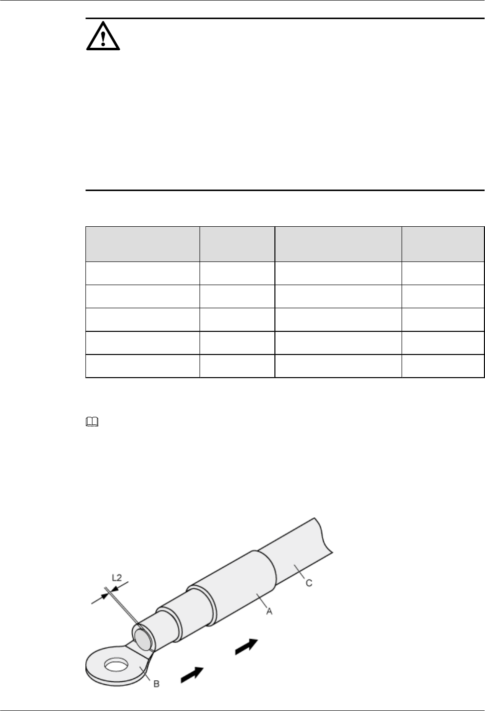
NOTICE
lWhen you strip a power cable, do not damage the conductor of the cable.
lIf the bare crimping terminal is not provided by Huawei, the value of L1 is 1 mm to 2 mm
greater than the value of L.
lAdd OT terminals to the power cable immediately after stripping a length of insulation jacket
off a power cable. Otherwise, the bare wires may distract from the center of the cable, which
affects the installation of OT terminals.
lIf the bare wires distract and OT terminals cannot be installed, cut off the bare wires, strip
another length of insulation jacket off the cable, and add OT terminals to the cable.
Table 16-1 Mapping between the cross-sectional area of the conductor and the value of L1
Cross-Sectional Area
of Conductor
Value of L1 Cross-Sectional Area of
Conductor
Value of L1
1 mm27 mm 10 mm211 mm
1.5 mm27 mm 16 mm213 mm
2.5 mm27 mm 25 mm214 mm
4 mm28 mm 35 mm216 mm
6 mm29 mm 50 mm216 mm
NOTE
If you are proficient in assembling OT terminals and power cables, you can obtain the value of L1 by
comparing the part to be crimped with the power cable.
Step 2 Put the heat-shrinkable (A) tube onto the bare crimping terminal, as shown in Figure 16-4.
Figure 16-4 Putting the heat shrink tubing onto the bare crimping terminal
AAU3940
Installation Guide 16 Appendix
Issue 01 (2015-01-15) Huawei Proprietary and Confidential
Copyright © Huawei Technologies Co., Ltd.
100
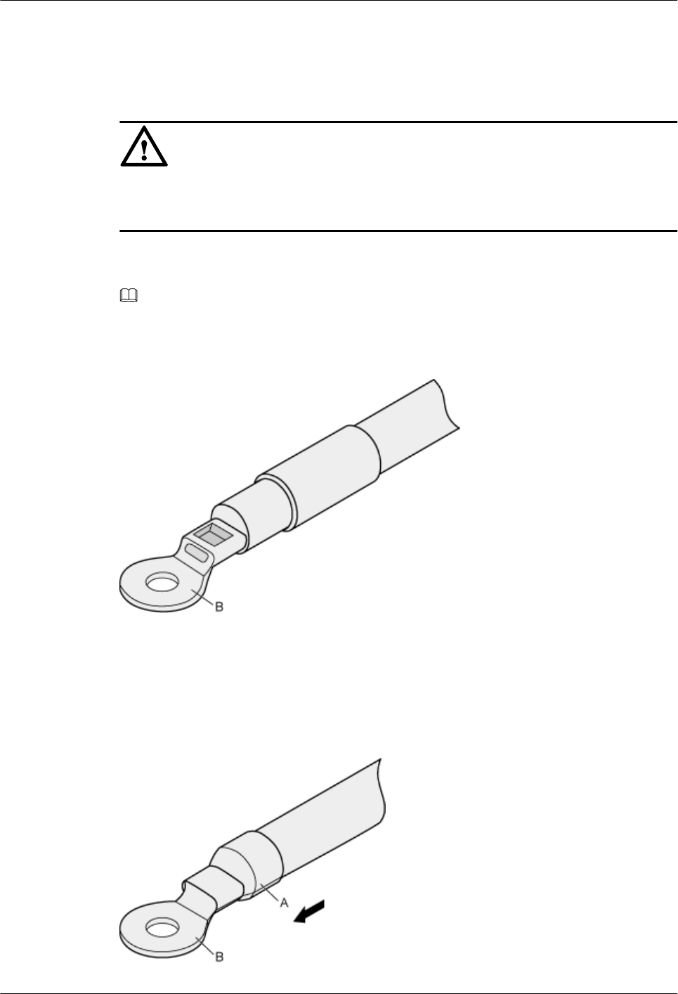
Step 3 Put the OT terminal onto the exposed conductor, and ensure that the OT terminal is in good
contact with the insulation layer of the power cable, as shown in Figure 16-4.
NOTICE
After the conductor is fed into the OT terminal, the protruding part of the conductor, or L2 in
Figure 16-4, must not be longer than 2 mm.
Step 4 Crimp the joint parts of the bare crimping terminal and the conductor, as shown in Figure
16-5.
NOTE
The shapes of crimped parts may vary with the crimping dies.
Figure 16-5 Crimping the joint parts of the bare crimping terminal and the conductor
Step 5 Push the heat shrink tubing (A) towards the connector until the tube covers the crimped part,
and then heat the tube by using a heat gun, as shown in Figure 16-6.
Figure 16-6 Heating the heat shrink tubing
AAU3940
Installation Guide 16 Appendix
Issue 01 (2015-01-15) Huawei Proprietary and Confidential
Copyright © Huawei Technologies Co., Ltd.
101
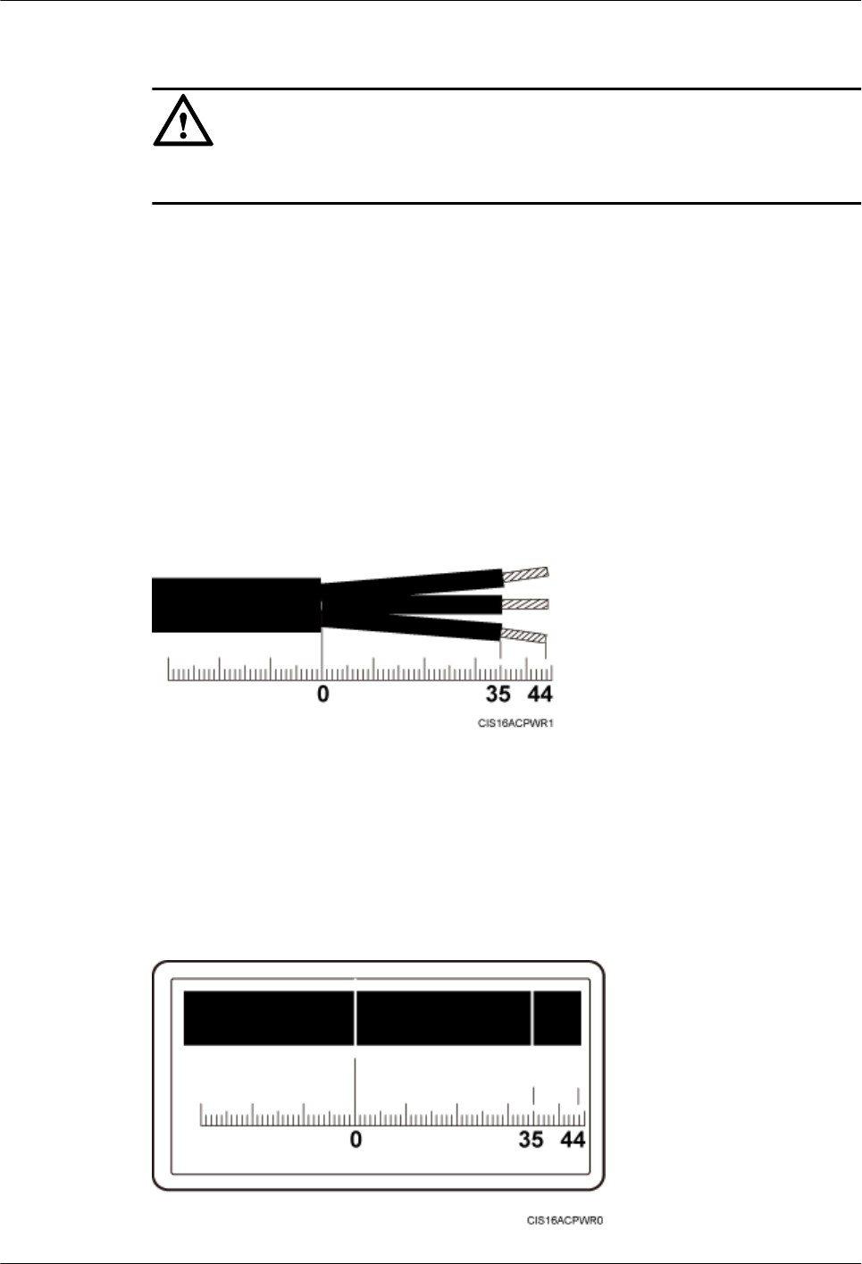
NOTICE
When you heat the heat shrink tubing, do not heat it with too much time.
----End
16.2 Adding a Tool-Less Female Connector (Pressfit Type)
to an AAU Power Cable on the AAU Side
This section describes the procedure for adding a tool-less female connector (pressfit type) to
an AAU power cable on the AAU side.
Context
The following figure shows the cable diagram on the label for an AAU power cable.
Figure 16-7 Cable diagram on the label for an AAU power cable
Procedure
Step 1 Determine the length of the power cable for different operations based on the cable diagram on
the label for a power cable, as shown in the following figure.
Figure 16-8 Determining the length of a power cable
AAU3940
Installation Guide 16 Appendix
Issue 01 (2015-01-15) Huawei Proprietary and Confidential
Copyright © Huawei Technologies Co., Ltd.
102
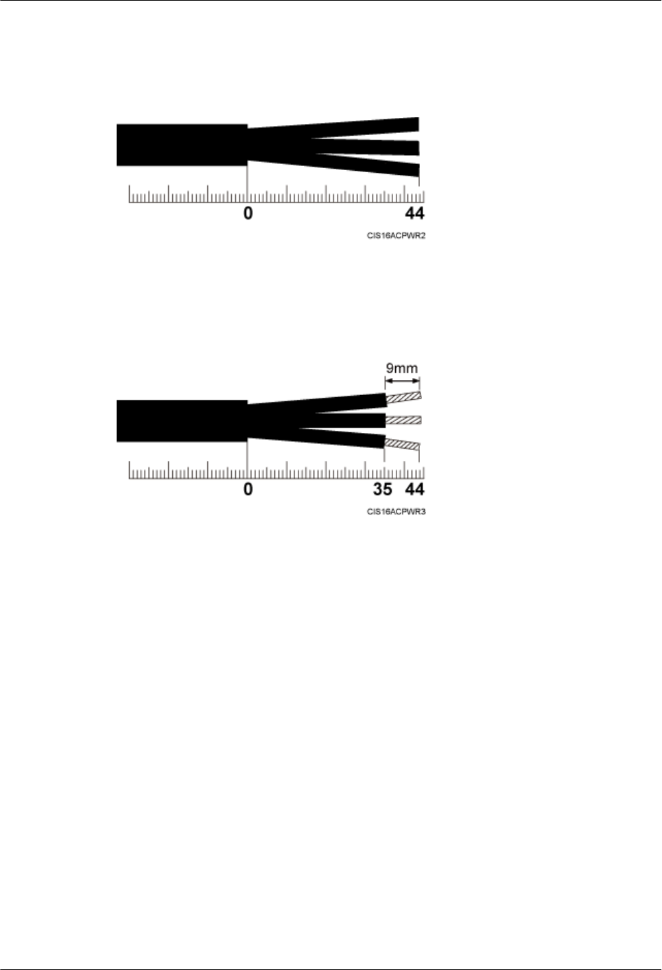
Step 2 Strip a specified length of sheath off the power cable, as shown in the following figure.
Figure 16-9 Stripping a specified length of sheath
Step 3 Strip the sheath off each core wire, as shown in the following figure.
Figure 16-10 Stripping the sheath off each wire
Step 4 Add a tool-less female connector (pressfit type) to three core wires, as shown in the following
figure.
1. Slide the sliding block on the connector outwards along the direction shown by the arrow.
2. Use an M3 Phillips torque screwdriver to loosen the two screws.
3. Use the M3 Phillips torque screwdriver to loosen the one screw on the other side.
4. Connect the brown core wire to the L port, the blue core wire to the N port, and the green
and yellow core wire to the PE port. Then, use the M3 Phillips torque screwdriver to tighten
the screws to 0.5 N·m (4.425 lbf·in.), as shown in the following figure.
5. Slide the sliding block on the connector inwards along the direction shown by the arrow.
AAU3940
Installation Guide 16 Appendix
Issue 01 (2015-01-15) Huawei Proprietary and Confidential
Copyright © Huawei Technologies Co., Ltd.
103
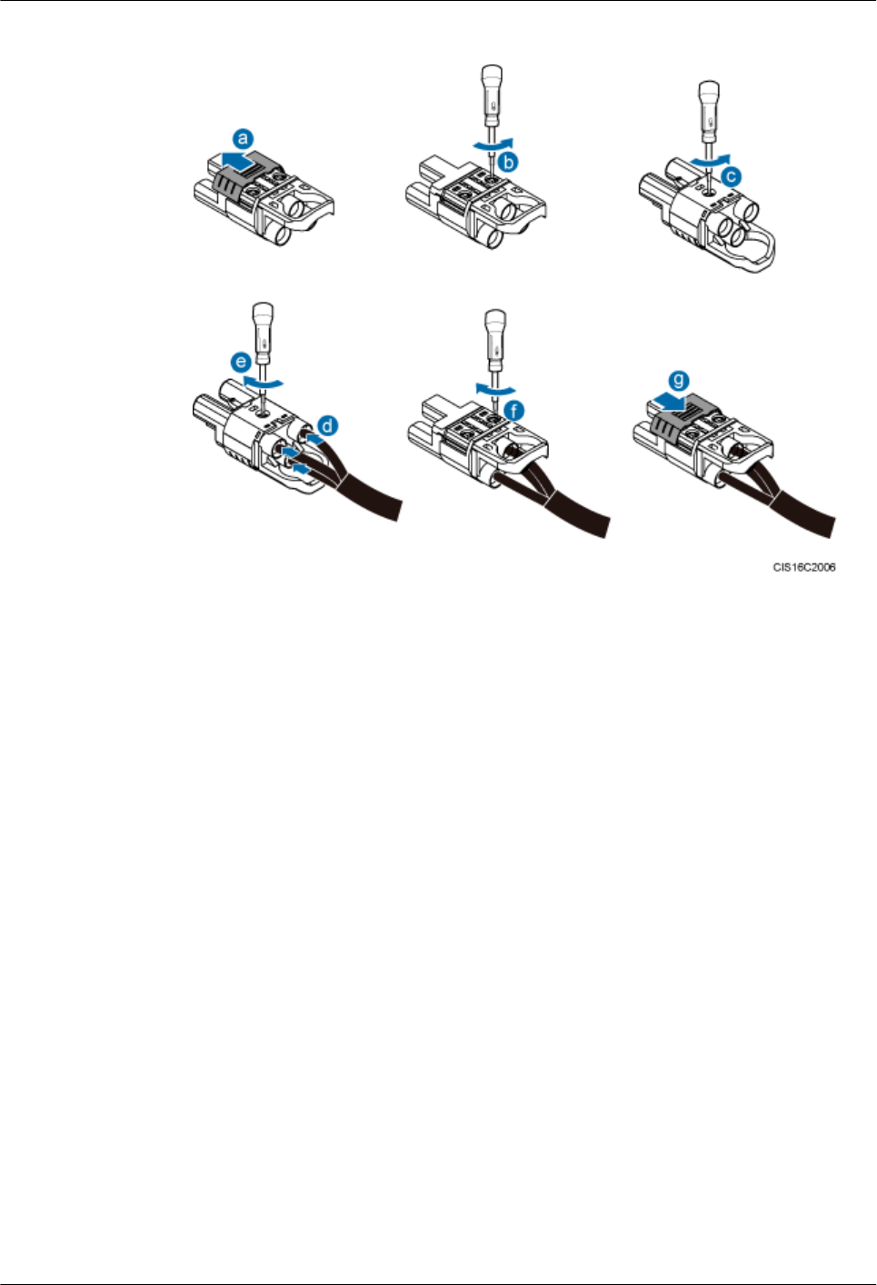
Figure 16-11 Adding a tool-less female connector (pressfit type) to core wires
----End
AAU3940
Installation Guide 16 Appendix
Issue 01 (2015-01-15) Huawei Proprietary and Confidential
Copyright © Huawei Technologies Co., Ltd.
104