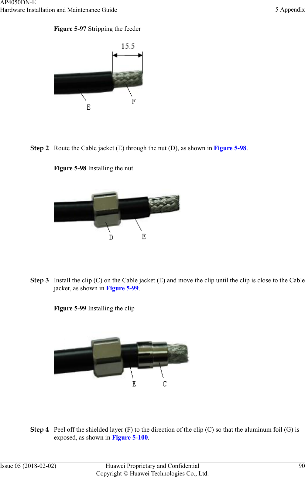
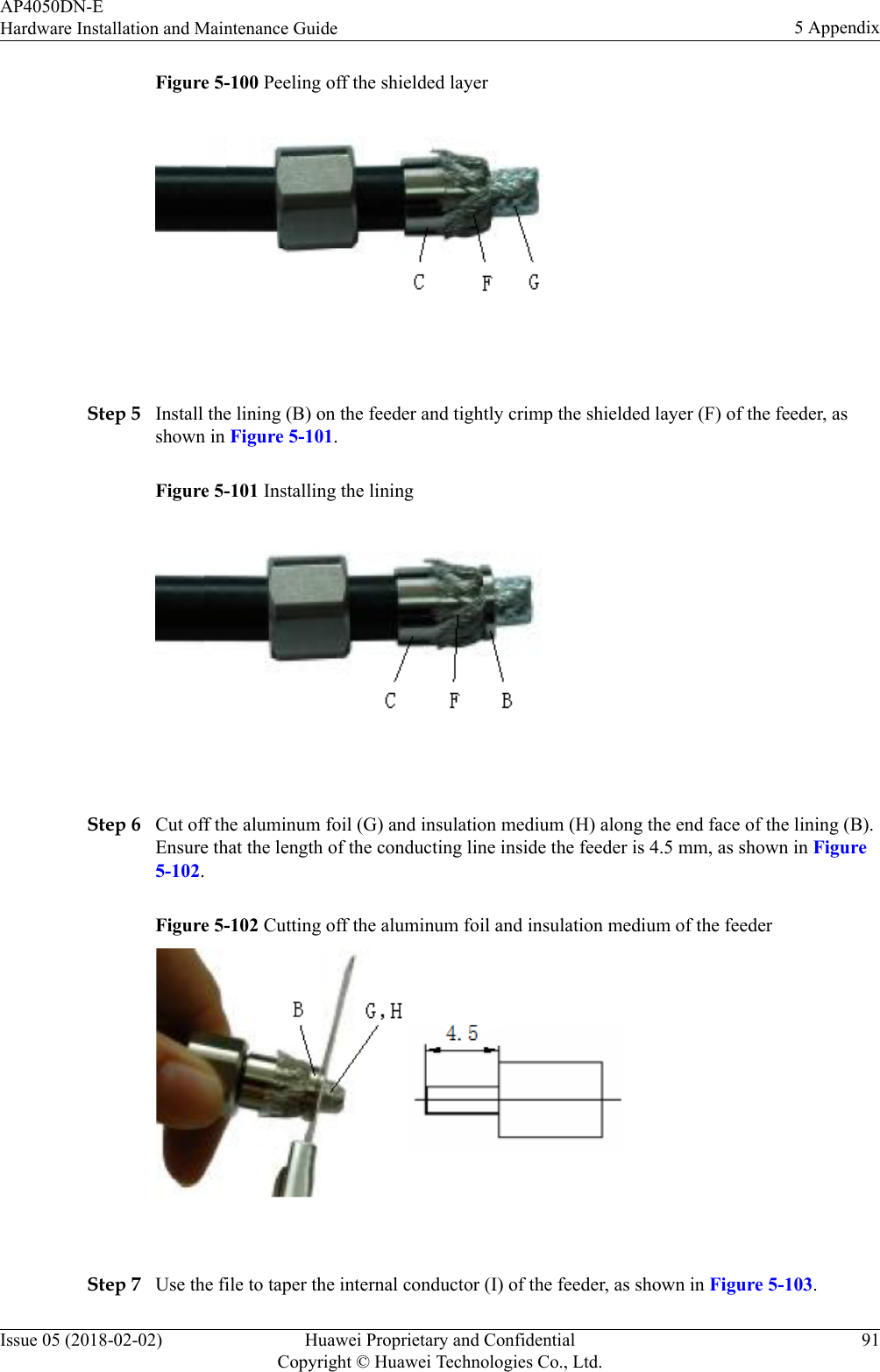
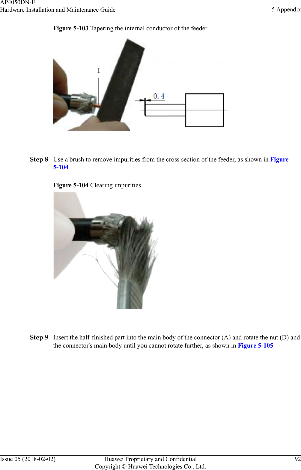
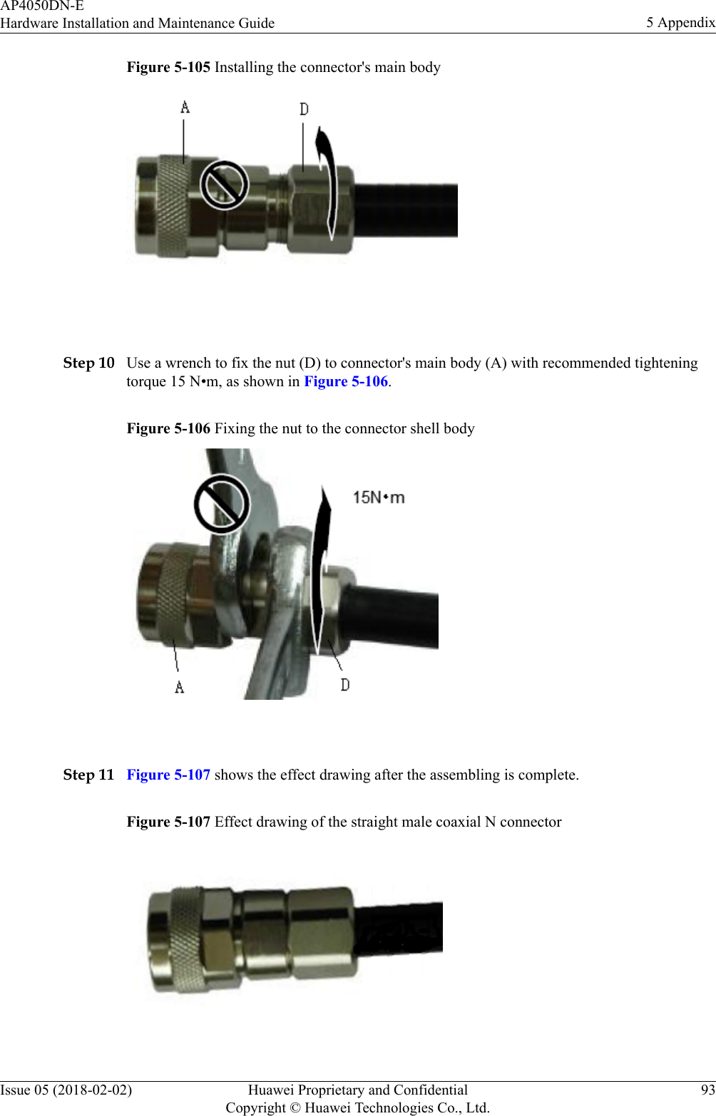
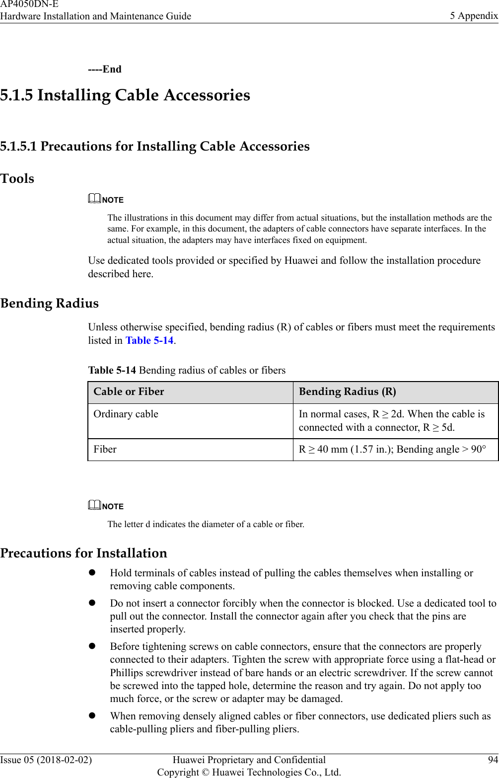
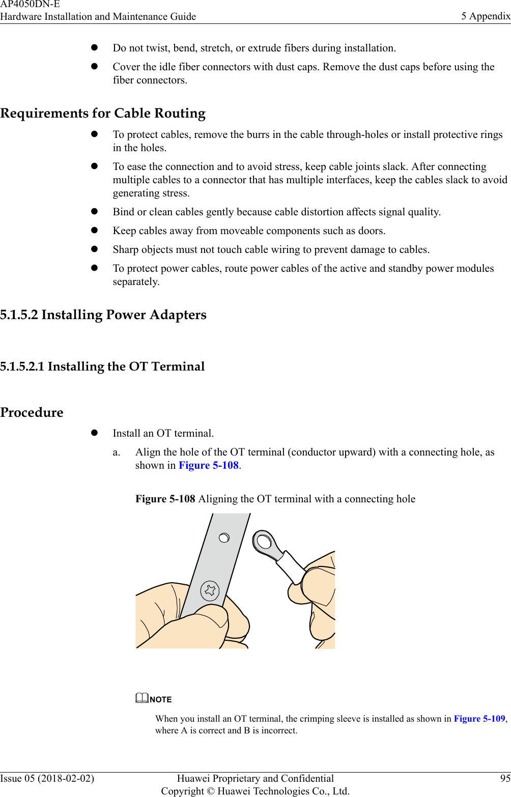
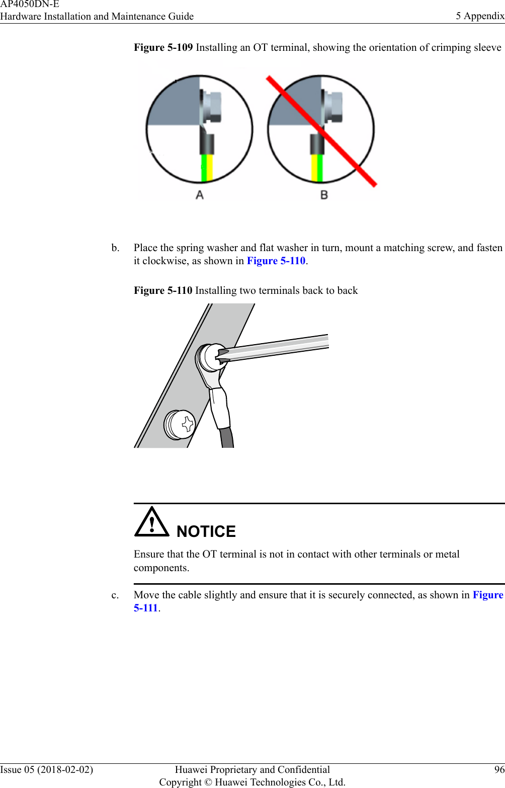
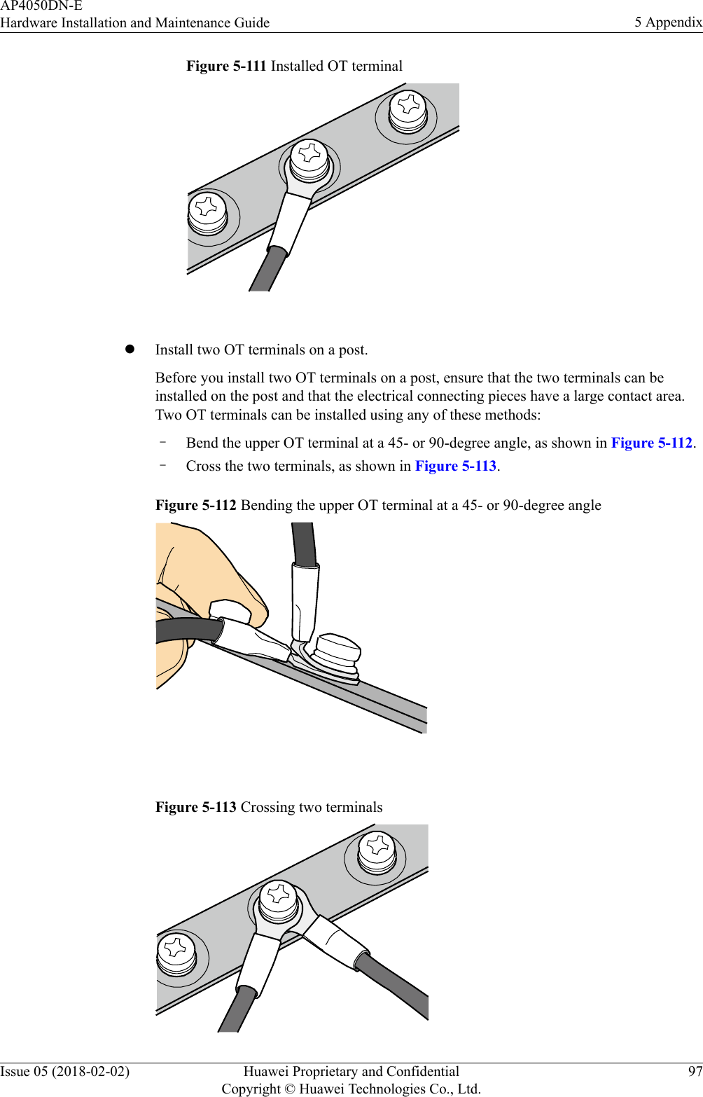
Huawei Technologies AP4050DN-E Wireless LAN Access Point User Manual Hardware Installation and Maintenance Guide
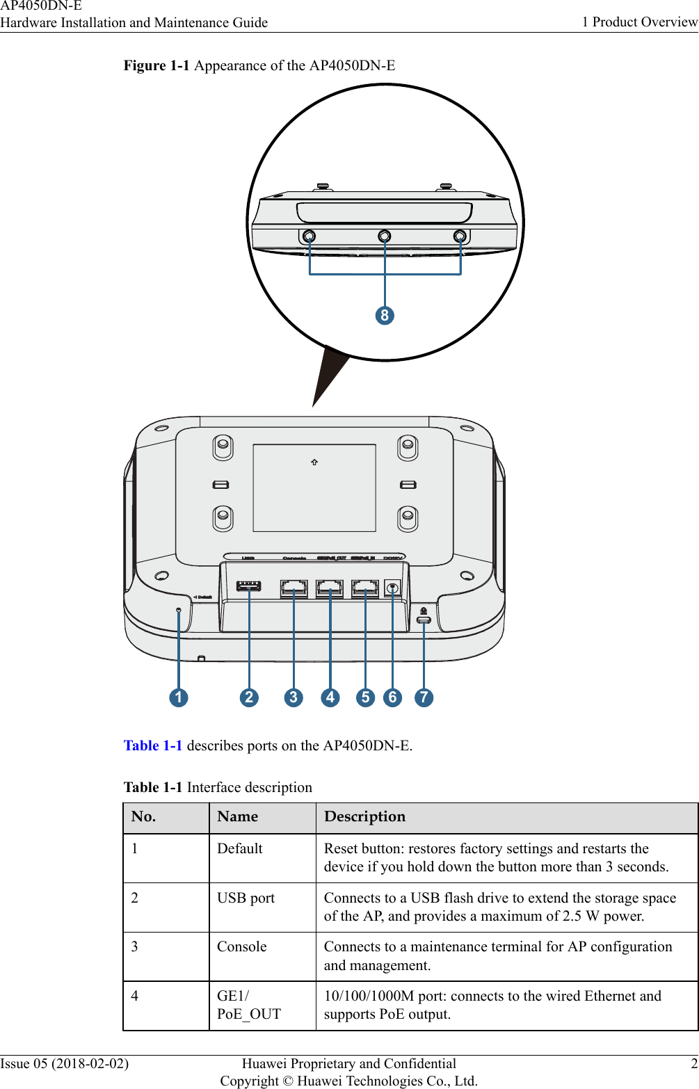
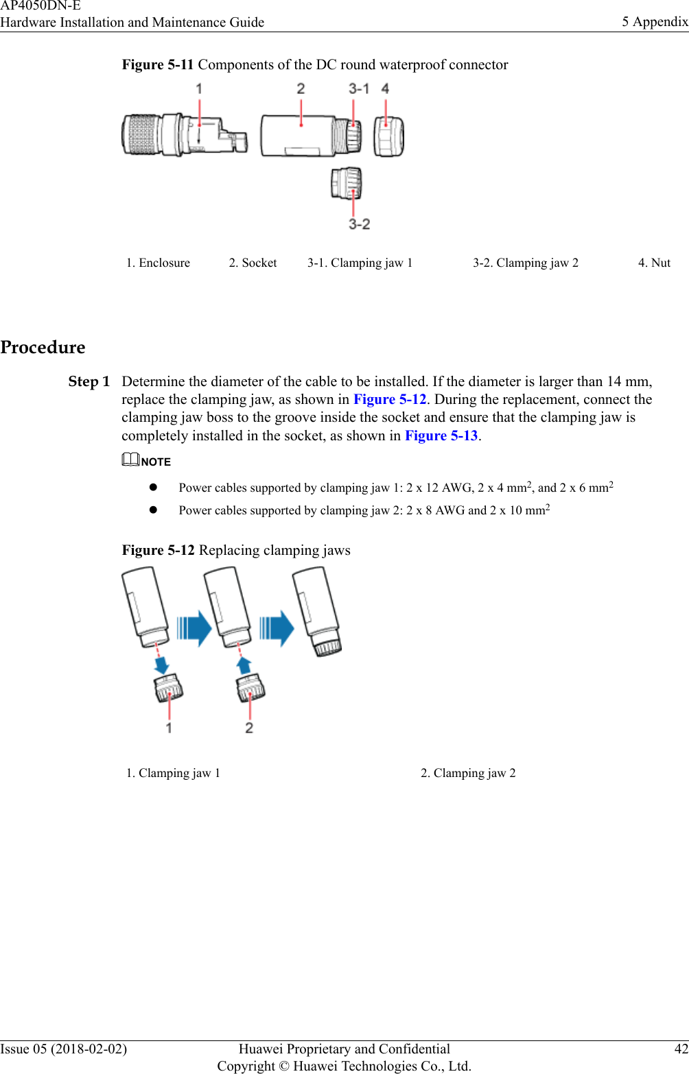
Huawei Technologies Co.,Ltd Wireless LAN Access Point Hardware Installation and Maintenance Guide
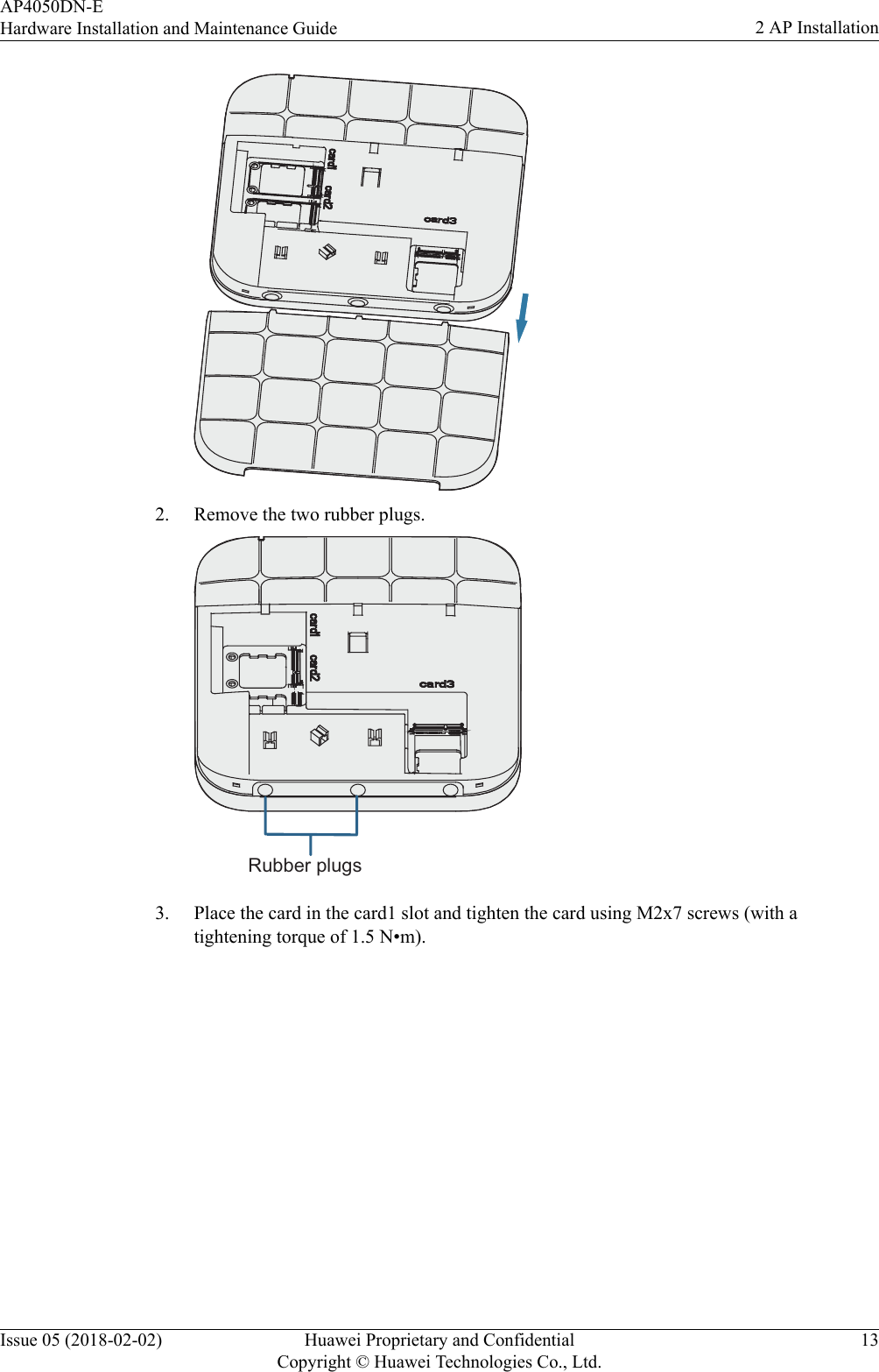
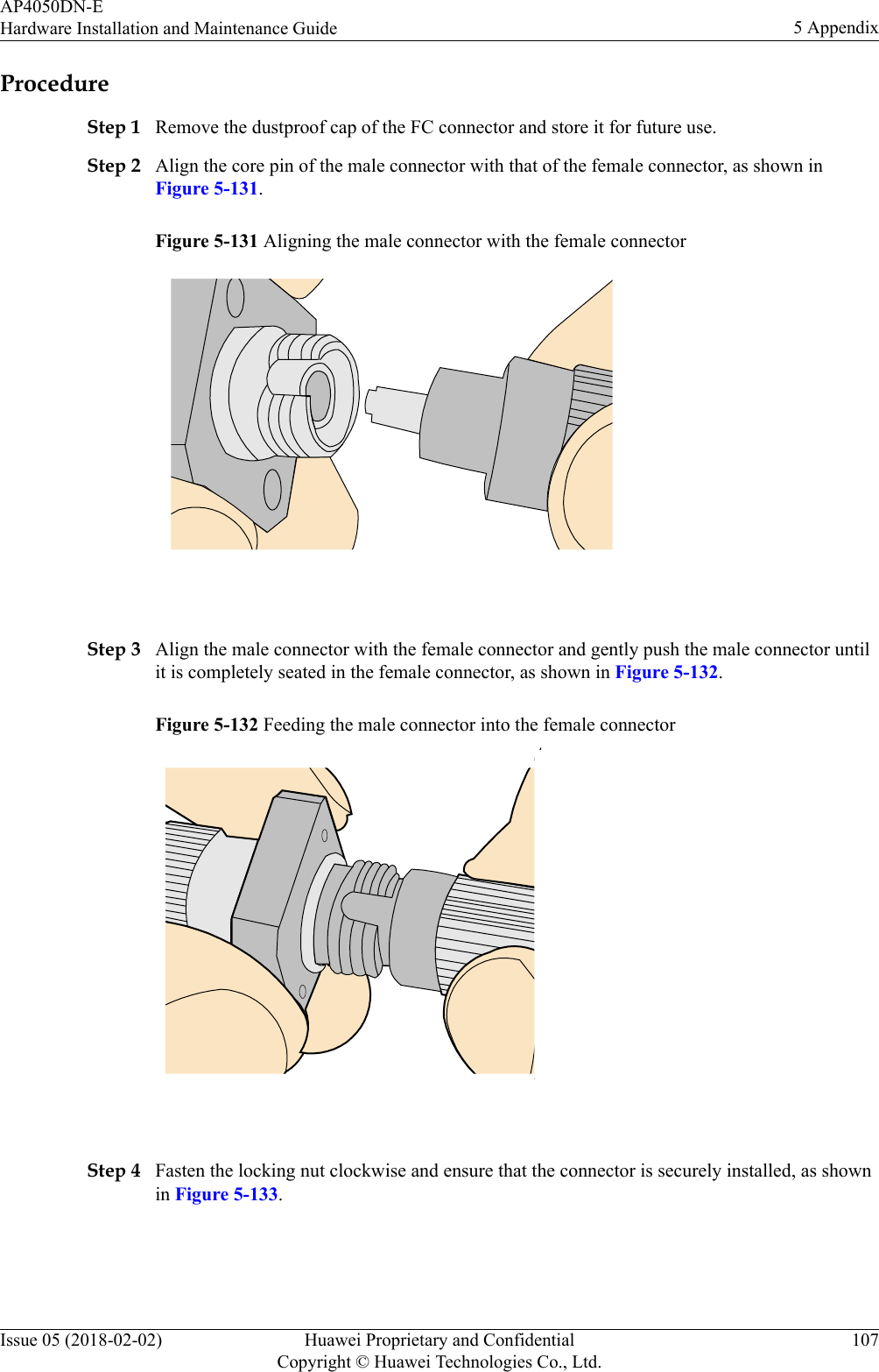
Contents
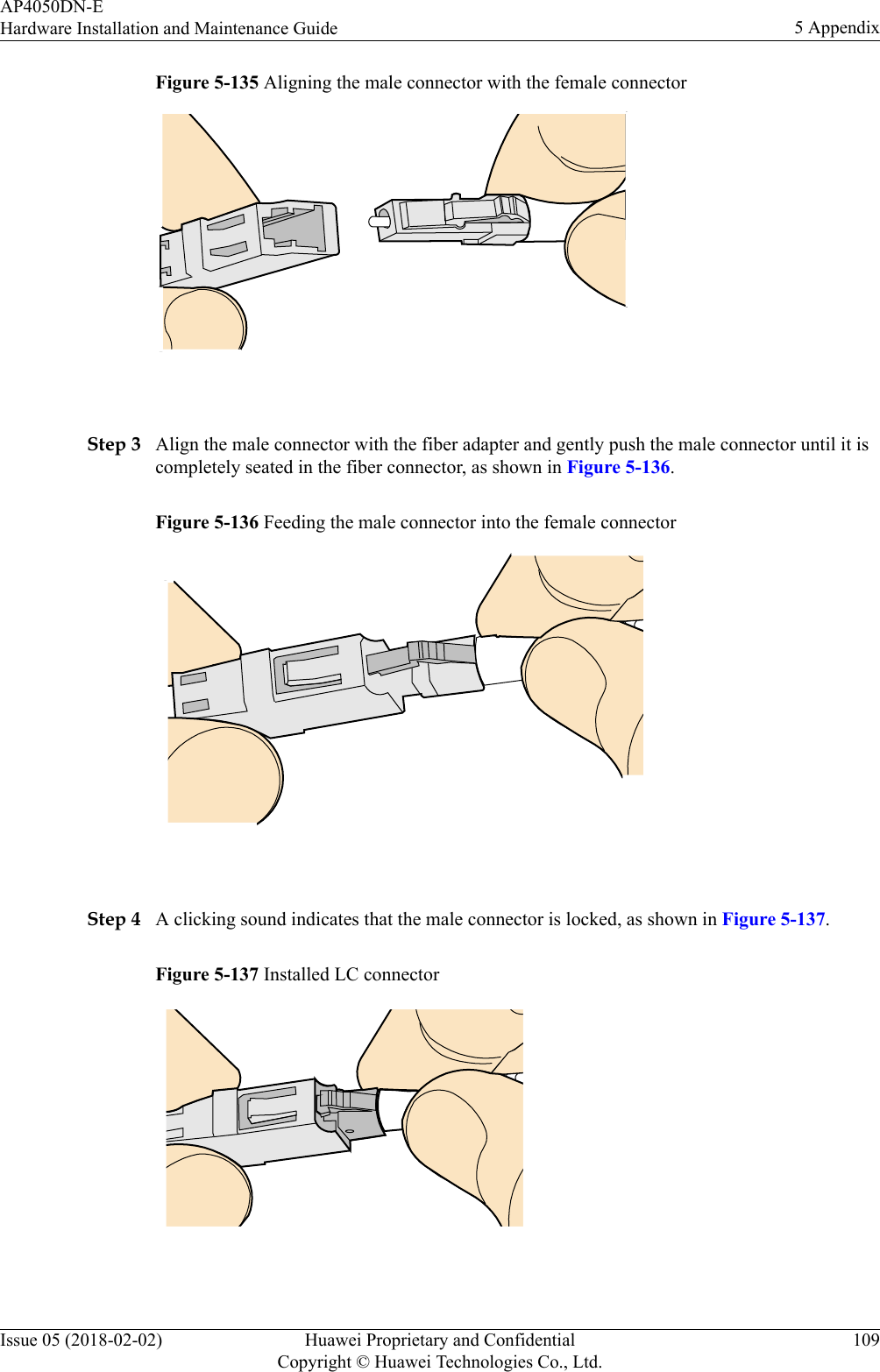
- 1. Usermanual
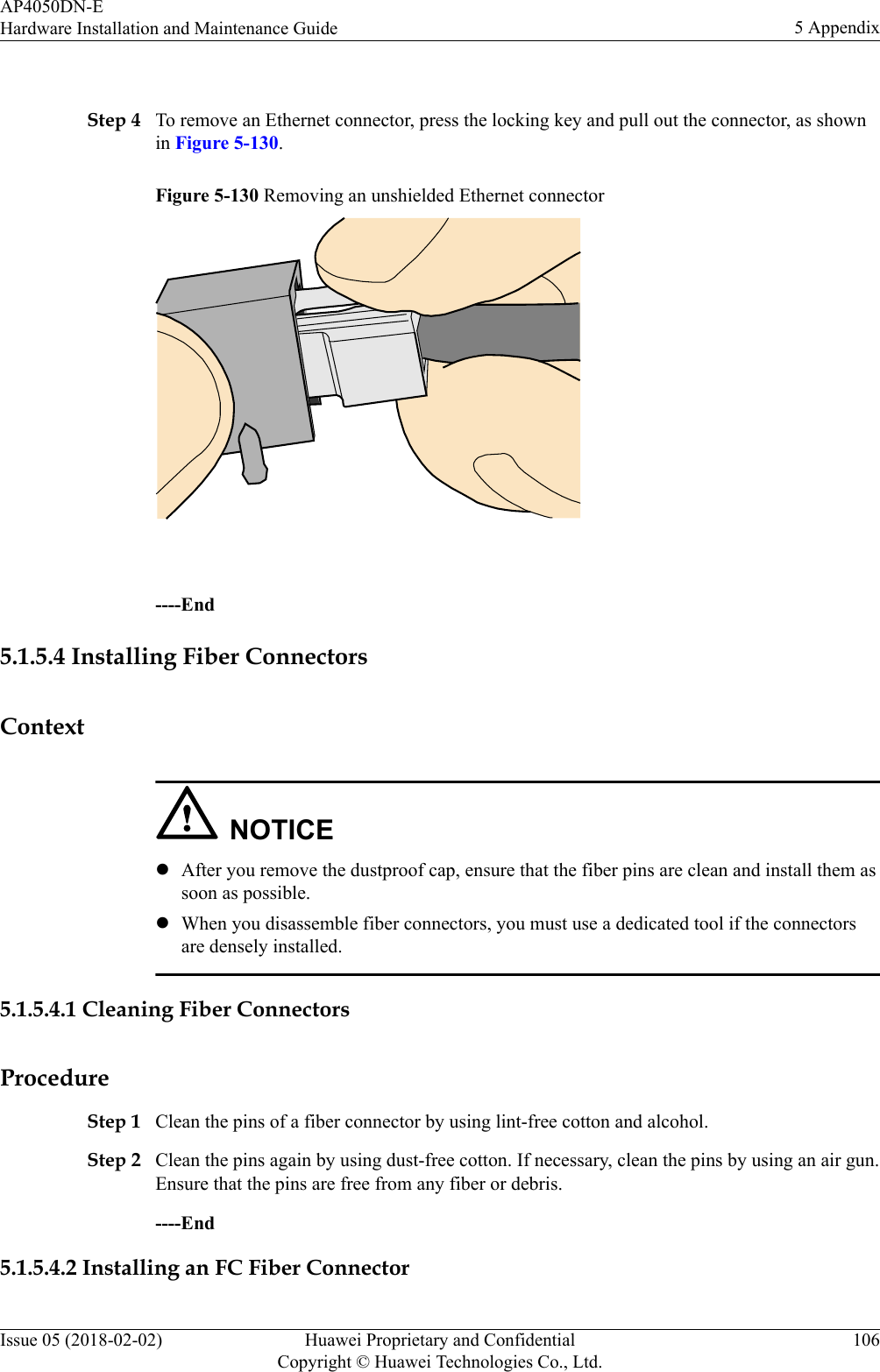
- 2. Usermanual-V1
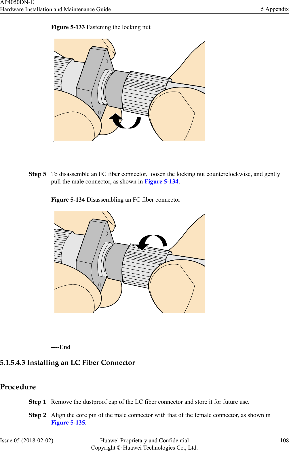
Usermanual