Huawei Technologies AP4050DN-E Wireless LAN Access Point User Manual Hardware Installation and Maintenance Guide
Huawei Technologies Co.,Ltd Wireless LAN Access Point Hardware Installation and Maintenance Guide
Contents
- 1. Usermanual
- 2. Usermanual-V1
Usermanual

AP4050DN-E
Hardware Installation and
Maintenance Guide
Issue 05
Date 2018-02-02
HUAWEI TECHNOLOGIES CO., LTD.

Copyright © Huawei Technologies Co., Ltd. 2018. All rights reserved.
No part of this document may be reproduced or transmitted in any form or by any means without prior written
consent of Huawei Technologies Co., Ltd.
Trademarks and Permissions
and other Huawei trademarks are trademarks of Huawei Technologies Co., Ltd.
All other trademarks and trade names mentioned in this document are the property of their respective
holders.
Notice
The purchased products, services and features are stipulated by the contract made between Huawei and the
customer. All or part of the products, services and features described in this document may not be within the
purchase scope or the usage scope. Unless otherwise specified in the contract, all statements, information,
and recommendations in this document are provided "AS IS" without warranties, guarantees or
representations of any kind, either express or implied.
The information in this document is subject to change without notice. Every effort has been made in the
preparation of this document to ensure accuracy of the contents, but all statements, information, and
recommendations in this document do not constitute a warranty of any kind, express or implied.
Huawei Technologies Co., Ltd.
Address: Huawei Industrial Base
Bantian, Longgang
Shenzhen 518129
People's Republic of China
Website: http://e.huawei.com
Issue 05 (2018-02-02) Huawei Proprietary and Confidential
Copyright © Huawei Technologies Co., Ltd.
i
About This Document
Overview
This document describes hardware features of the AP4050DN-E and provides basic
installation methods.
Intended Audience
This document is intended for network engineers responsible for WLAN installation and
maintenance. You should have experience in network device installation and maintenance.
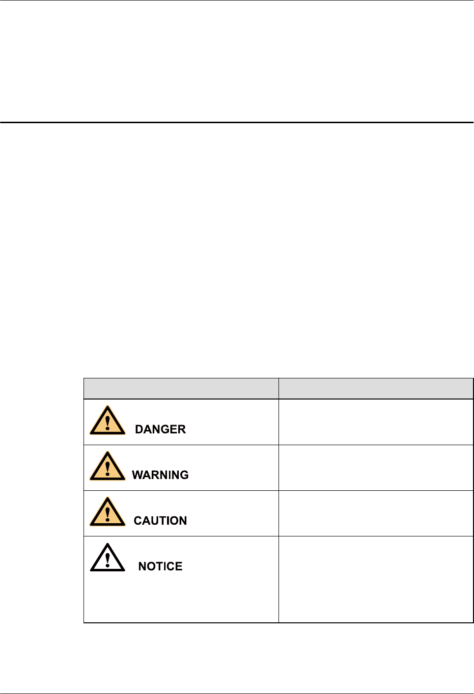
Symbol Conventions
The symbols that may be found in this document are defined as follows.
Symbol Description
Indicates an imminently hazardous situation
which, if not avoided, will result in death or
serious injury.
Indicates a potentially hazardous situation
which, if not avoided, could result in death
or serious injury.
Indicates a potentially hazardous situation
which, if not avoided, may result in minor
or moderate injury.
Indicates a potentially hazardous situation
which, if not avoided, could result in
equipment damage, data loss, performance
deterioration, or unanticipated results.
NOTICE is used to address practices not
related to personal injury.
AP4050DN-E
Hardware Installation and Maintenance Guide About This Document
Issue 05 (2018-02-02) Huawei Proprietary and Confidential
Copyright © Huawei Technologies Co., Ltd.
ii

Symbol Description
NOTE
Calls attention to important information,
best practices and tips.
NOTE is used to address information not
related to personal injury, equipment
damage, and environment deterioration.
Change History
Changes between document issues are cumulative. The latest document issue contains all
changes made in previous issues.
Issue 05 (2018-02-02)
This version has the following updates:
The following information is modified:
l2.6.1 Installing the Device on a Wall
l2.6.2 Installing the Device on a Ceiling
l2.6.3 Installing the Device on a T-rail
l2.6.4 Removing an AP
Issue 04 (2017-08-31)
This version has the following updates:
The following information is modified:
l1.1 Device Structure
l2.3 Unpacking the Equipment
Issue 03 (2017-01-20)
This version has the following updates:
The following information is modified:
l2.6.1 Installing the Device on a Wall
l2.6.2 Installing the Device on a Ceiling
l2.6.3 Installing the Device on a T-rail
Issue 02 (2016-09-30)
This version has the following updates:
The following information is modified:
2.7 Cable Connection
AP4050DN-E
Hardware Installation and Maintenance Guide About This Document
Issue 05 (2018-02-02) Huawei Proprietary and Confidential
Copyright © Huawei Technologies Co., Ltd.
iii

Issue 01 (2016-07-22)
Initial commercial release
AP4050DN-E
Hardware Installation and Maintenance Guide About This Document
Issue 05 (2018-02-02) Huawei Proprietary and Confidential
Copyright © Huawei Technologies Co., Ltd.
iv

Contents
About This Document.....................................................................................................................ii
1 Product Overview..........................................................................................................................1
1.1 Device Structure............................................................................................................................................................. 1
1.2 Indicator Description...................................................................................................................................................... 3
1.3 Basic Specifications........................................................................................................................................................4
1.4 Ordering Information......................................................................................................................................................5
2 AP Installation............................................................................................................................... 6
2.1 Preparing for Installation................................................................................................................................................ 6
2.2 Installation Flowchart..................................................................................................................................................... 8
2.3 Unpacking the Equipment.............................................................................................................................................. 8
2.4 Determining the Installation Position............................................................................................................................. 9
2.5 Installing an IoT Card...................................................................................................................................................10
2.6 Installing the AP........................................................................................................................................................... 14
2.6.1 Installing the Device on a Wall..................................................................................................................................14
2.6.2 Installing the Device on a Ceiling............................................................................................................................. 17
2.6.3 Installing the Device on a T-rail................................................................................................................................ 18
2.6.4 Removing an AP........................................................................................................................................................20
2.7 Cable Connection......................................................................................................................................................... 20
2.8 Connecting the Security Lock...................................................................................................................................... 23
2.9 Checking the Device After Installation........................................................................................................................ 23
2.10 Powering on the AP....................................................................................................................................................24
3 Logging In to the Device............................................................................................................ 25
3.1 Logging In to the Device Using STelnet/Telnet........................................................................................................... 25
3.2 Logging In to the Device Through the Web System.................................................................................................... 27
3.3 Logging In to the Device Through the Console Port....................................................................................................29
4 Hardware Failures....................................................................................................................... 32
4.1 A Device Fails to Be Powered On................................................................................................................................32
5 Appendix.......................................................................................................................................35
5.1 On-site Cable Assembly and Installation..................................................................................................................... 35
5.1.1 Cable Assembly Precautions..................................................................................................................................... 35
5.1.2 Assembling Power Cables......................................................................................................................................... 36
AP4050DN-E
Hardware Installation and Maintenance Guide Contents
Issue 05 (2018-02-02) Huawei Proprietary and Confidential
Copyright © Huawei Technologies Co., Ltd.
v

5.1.2.1 Assembling a DC 2-Pin Round Connector (A)...................................................................................................... 36
5.1.2.2 Assembling a DC 2-Pin Round Connector (B)...................................................................................................... 41
5.1.2.3 Assembling the OT Terminal and Power Cable..................................................................................................... 47
5.1.2.4 Assembling the JG Terminal and Power Cable...................................................................................................... 51
5.1.2.5 Assembling the Cord End Terminal and the Power Cable..................................................................................... 53
5.1.3 Assembling Ethernet Cables......................................................................................................................................56
5.1.3.1 Assembling the Shielded RJ45 Connector and Ethernet Cable..............................................................................56
5.1.3.2 Assembling an Optimized Shielded RJ45 Connector and SFTP Network Cables.................................................62
5.1.3.3 Assembling an Integrated Shielded RJ45 Connector and SFTP Network Cables................................................. 66
5.1.3.4 Assembling a Shielded RJ45 Connector and an FTP Network Cable....................................................................70
5.1.3.5 Assembling an Unshielded RJ45 Connector and Ethernet Cable...........................................................................75
5.1.3.6 Checking the Appearance of Contact Strips...........................................................................................................77
5.1.3.7 Testing the Connection of Assembled Cables........................................................................................................ 80
5.1.3.8 Common Network Cable Faults and Preventive Measures.................................................................................... 83
5.1.4 Assembling Feeders...................................................................................................................................................84
5.1.4.1 Assembling the Straight Male Coaxial N Connector and the 1/2'' Feeder............................................................. 84
5.1.4.2 Assembling a Straight Male Coaxial N Connector and an RG8U Feeder..............................................................88
5.1.5 Installing Cable Accessories......................................................................................................................................94
5.1.5.1 Precautions for Installing Cable Accessories......................................................................................................... 94
5.1.5.2 Installing Power Adapters...................................................................................................................................... 95
5.1.5.2.1 Installing the OT Terminal...................................................................................................................................95
5.1.5.2.2 Installing the Cord End Terminal........................................................................................................................ 98
5.1.5.2.3 Installing a 2-Pin Round Connector and a DC Power Cable...............................................................................99
5.1.5.3 Installing Ethernet Adapters................................................................................................................................. 102
5.1.5.3.1 Installing a Shielded Ethernet Connector.......................................................................................................... 103
5.1.5.3.2 Installing an Unshielded Ethernet Connector....................................................................................................104
5.1.5.4 Installing Fiber Connectors.................................................................................................................................. 106
5.1.5.4.1 Cleaning Fiber Connectors................................................................................................................................ 106
5.1.5.4.2 Installing an FC Fiber Connector...................................................................................................................... 106
5.1.5.4.3 Installing an LC Fiber Connector...................................................................................................................... 108
5.1.5.4.4 Installing the SC Fiber Connector..................................................................................................................... 110
5.1.5.4.5 Installing an MPO Connector............................................................................................................................ 111
5.1.6 Replacing the Mold of the Crimping Tool...............................................................................................................113
5.2 Environmental Requirements for Device Operation.................................................................................................. 116
5.2.1 Environmental Requirements for an Equipment Room...........................................................................................116
5.2.1.1 Requirements for Selecting a Site for an Equipment Room.................................................................................116
5.2.1.2 Equipment Room Layout......................................................................................................................................117
5.2.1.3 Construction Requirements for the Equipment Room..........................................................................................118
5.2.1.4 Equipment Room Environment............................................................................................................................ 119
5.2.1.5 Requirements for Corrosive Gases....................................................................................................................... 120
5.2.1.6 Requirements for ESD Prevention....................................................................................................................... 121
5.2.1.7 Electromagnetism Requirements for the Equipment Room................................................................................. 121
AP4050DN-E
Hardware Installation and Maintenance Guide Contents
Issue 05 (2018-02-02) Huawei Proprietary and Confidential
Copyright © Huawei Technologies Co., Ltd.
vi

5.2.1.8 Requirements for Lightning Proof Grounding..................................................................................................... 121
5.2.2 Requirements for Power Supply..............................................................................................................................123
5.2.2.1 Requirements for AC Power Supply.................................................................................................................... 123
5.2.2.2 Recommendations for AC Power Supply.............................................................................................................124
5.2.2.3 Requirements for DC Power Supply.................................................................................................................... 125
5.2.2.4 Recommendations for DC Power Supply.............................................................................................................125
5.3 Equipment Grounding Specifications.........................................................................................................................126
5.3.1 General Grounding Specifications...........................................................................................................................126
5.3.2 Grounding Specifications for an Equipment Room................................................................................................ 126
5.3.3 Grounding Specifications for Devices.....................................................................................................................126
5.3.4 Grounding Specifications for Communications Power Supply...............................................................................127
5.3.5 Grounding Specifications for Signal Cables........................................................................................................... 128
5.3.6 Specifications for Laying Out Grounding Cables................................................................................................... 128
5.4 Engineering Labels for Cables................................................................................................................................... 129
5.4.1 Introduction to Labels..............................................................................................................................................129
5.4.1.1 Label Materials..................................................................................................................................................... 129
5.4.1.2 Type and Structure................................................................................................................................................130
5.4.1.3 Label Printing....................................................................................................................................................... 131
5.4.1.4 Writing Labels...................................................................................................................................................... 133
5.4.1.5 Attaching Labels...................................................................................................................................................134
5.4.1.6 Contents of Engineering Labels........................................................................................................................... 136
5.4.1.7 Precautions for Using Engineering Labels........................................................................................................... 136
5.4.2 Engineering Labels for Optical Fibers.....................................................................................................................137
5.4.2.1 Labels for the Optical Fibers Connecting Devices...............................................................................................137
5.4.2.2 Labels for the Optical Fibers Connecting the Device and an ODF...................................................................... 138
5.4.3 Engineering Labels for Network Cables................................................................................................................. 139
5.4.4 Engineering Labels for User Cables........................................................................................................................141
5.4.5 Engineering Labels for Power Cables..................................................................................................................... 142
5.4.5.1 Engineering Labels for DC Power Cables............................................................................................................142
5.4.5.2 Engineering Labels for AC Power Cables............................................................................................................143
5.5 Guide to Using Optical Modules................................................................................................................................ 144
5.6 Fault Tag..................................................................................................................................................................... 148
5.7 Installation Checklist.................................................................................................................................................. 149
5.8 Guide to Making Drip Loops......................................................................................................................................156
5.9 Power Adaptation Solution.........................................................................................................................................158
AP4050DN-E
Hardware Installation and Maintenance Guide Contents
Issue 05 (2018-02-02) Huawei Proprietary and Confidential
Copyright © Huawei Technologies Co., Ltd.
vii

1 Product Overview
About This Chapter
The AP4050DN-E has the following advantages:
l2x2 MIMO
lGood service support capabilities
lHigh reliability
lHigh security
lSimple network deployment
lAutomatic AC discovery and configuration
lReal-time management and maintenance
In compliance with 802.11ac Wave 2, the AP4050DN-E can provide gigabit access for
wireless users, greatly improving wireless user experience.
The AP4050DN-E provides basic 802.11n/ac WLANs for scenarios that can integrate
enhanced applications (such as Bluetooth and RFID), such as shopping malls, supermarkets,
healthcare, warehouse, manufacturing, and logistics. It provides flexible distribution options
in different environments.
A cloud AP must be used together with a cloud server.
1.1 Device Structure
1.2 Indicator Description
1.3 Basic Specifications
1.4 Ordering Information
1.1 Device Structure
Figure 1-1 shows the appearance of the AP4050DN-E.
AP4050DN-E
Hardware Installation and Maintenance Guide 1 Product Overview
Issue 05 (2018-02-02) Huawei Proprietary and Confidential
Copyright © Huawei Technologies Co., Ltd.
1
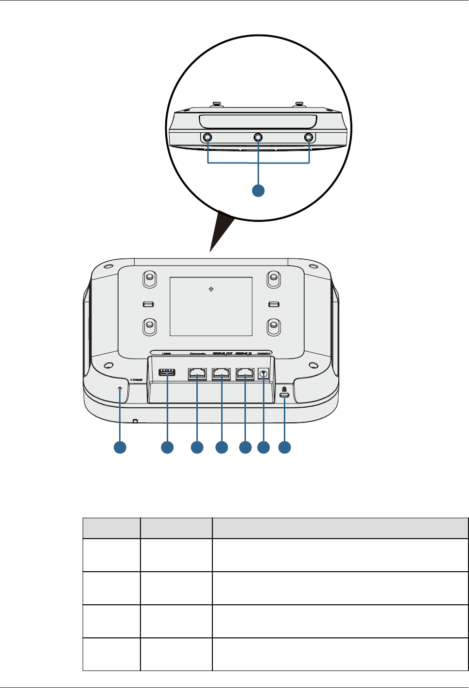
Figure 1-1 Appearance of the AP4050DN-E
6
23
175
4
8
Table 1-1 describes ports on the AP4050DN-E.
Table 1-1 Interface description
No. Name Description
1 Default Reset button: restores factory settings and restarts the
device if you hold down the button more than 3 seconds.
2 USB port Connects to a USB flash drive to extend the storage space
of the AP, and provides a maximum of 2.5 W power.
3 Console Connects to a maintenance terminal for AP configuration
and management.
4 GE1/
PoE_OUT
10/100/1000M port: connects to the wired Ethernet and
supports PoE output.
AP4050DN-E
Hardware Installation and Maintenance Guide 1 Product Overview
Issue 05 (2018-02-02) Huawei Proprietary and Confidential
Copyright © Huawei Technologies Co., Ltd.
2
No. Name Description
5 GE0/PoE_IN 10/100/1000M port: connects to the wired Ethernet and
supports PoE input.
6 DC 12V Connects a 12 V power adapter to the AP.
7 Security slot Connects to a security lock.
8 Radio port Connects an antenna to an IoT card through a radio cable.
NOTE
lThe AP supports the following power supply modes: PoE power supply and DC power supply.
lWhen the AP uses the DC power supply, use a power adapter for power supply; otherwise, the AP
may be damaged.
lFor power adapter models, see 5.9 Power Adaptation Solution.
1.2 Indicator Description
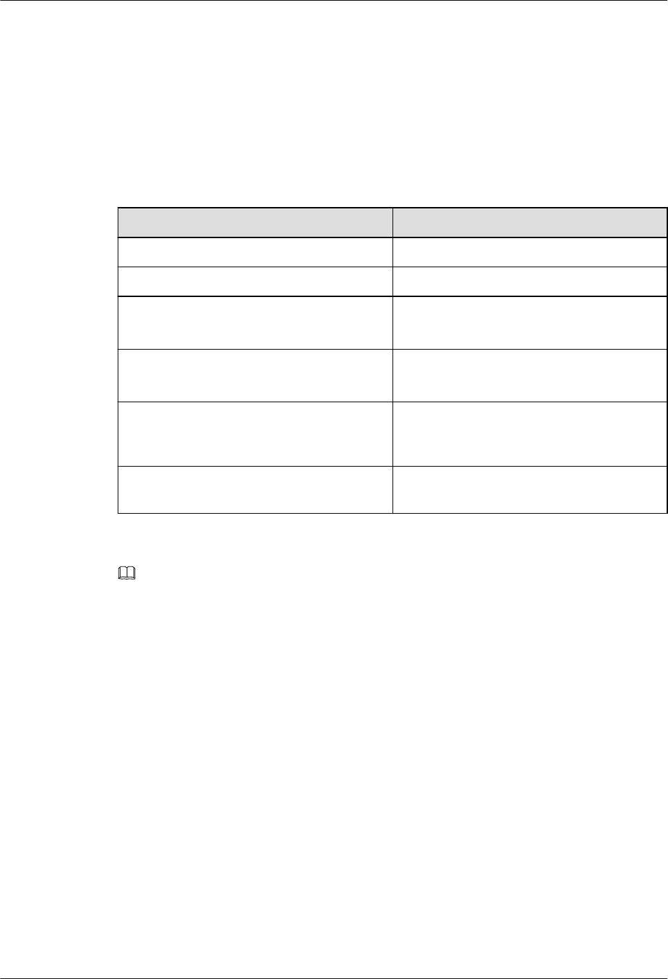
The AP4050DN-E provides only a single indicator, as shown in Figure 1-2.
NOTE
Indicator colors may vary slightly at different temperature.
Figure 1-2 Indicator
Indicator
Table 1-2 Description about the single indicator
Type Color Status Description
Default
status
after
power-on
Green Steady on The AP is just powered on and the software is not
started yet.
AP4050DN-E
Hardware Installation and Maintenance Guide 1 Product Overview
Issue 05 (2018-02-02) Huawei Proprietary and Confidential
Copyright © Huawei Technologies Co., Ltd.
3

Type Color Status Description
Software
startup
status
Green Steady on
after
blinking
once
After the system is reset and starts uploading the
software, the indicator blinks green once. Until the
software is uploaded and started, the indicator
remains steady green.
Running
status
Green Blinking
once
every 2s
(0.5 Hz)
lThe system is running properly, the Ethernet
connection is normal, and STAs are associated
with the AP.
lThe system enters the Uboot CLI.
Blinking
once
every 5s
(0.2 Hz)
The system is running properly, the Ethernet
connection is normal, and no STA is associated
with the AP. The system is in low power
consumption state.
Alarm Green Blinking
once
every
0.25s (4
Hz)
lThe software is being upgraded.
lAfter the software is loaded and started, the AP
requests to go online if it works in Fit AP or
cloud-based management mode. The indicator
remains in this state before the AP successfully
goes online.
lThe AP works in Fit AP or cloud-based
management mode and fails to go online.
Fault Red Steady on A fault that affects services has occurred, such as a
DRAM detection failure or system software
loading failure. The fault cannot be automatically
rectified and must be rectified manually.
1.3 Basic Specifications
Table 1-3 provides basic specifications of the AP4050DN-E.
Table 1-3 Basic specifications
Item Description
Physical
specifications
Dimensions (H x
W x D)
53 mm x 220 mm x 220 mm
Weight 0.84 kg
System memory l256 MB DDR3L
l64 MB NOR FLASH
Power
specifications
Power input lDC: 12 V ± 10%
lPoE power supply: in compliance with IEEE
802.3at
AP4050DN-E
Hardware Installation and Maintenance Guide 1 Product Overview
Issue 05 (2018-02-02) Huawei Proprietary and Confidential
Copyright © Huawei Technologies Co., Ltd.
4
Item Description
Maximum power
consumption
16.0 W (excluding the output power of the USB port,
IoT card, or PoE_OUT port)
NOTE
The actual maximum power consumption depends on local
laws and regulations.
Environment
specifications
Operating
temperature
l-60 m to +1800 m: -10°C to +50°C
l1800 m to 5000 m: Temperature decreases by 1°C
every time the altitude increases 300 m.
Storage
temperature
-40°C to +70°C
Operating
humidity
5% to 95% (non-condensing)
IP rating IP41
Atmospheric
pressure
53 kPa to 106 kPa
1.4 Ordering Information
To place an order, contact technical support personnel.
Part Number Description
50082944 AP4050DN-E Mainframe(11ac wave2,Dual Band,Built-in
Antenna,BT,USB,PSE,IoT Slot)
50083055 AP4050DN-E Mainframe Bundle (AP4050DN-E Mainframe*8)
AP4050DN-E
Hardware Installation and Maintenance Guide 1 Product Overview
Issue 05 (2018-02-02) Huawei Proprietary and Confidential
Copyright © Huawei Technologies Co., Ltd.
5

2 AP Installation
About This Chapter
2.1 Preparing for Installation
2.2 Installation Flowchart
2.3 Unpacking the Equipment
2.4 Determining the Installation Position
2.5 Installing an IoT Card
2.6 Installing the AP
2.7 Cable Connection
2.8 Connecting the Security Lock
2.9 Checking the Device After Installation
2.10 Powering on the AP
2.1 Preparing for Installation
This section describes safety precautions and tool preparations for AP installation.
Safety Precautions
lTake proper measures to prevent injuries and device damage.
lPlace the device in a dry and flat position away from any liquid and prevent the device
from slipping.
lKeep the device clean.
lDo not put the device and tools in the aisles.
AP4050DN-E
Hardware Installation and Maintenance Guide 2 AP Installation
Issue 05 (2018-02-02) Huawei Proprietary and Confidential
Copyright © Huawei Technologies Co., Ltd.
6
CAUTION
Only the qualified personnel are permitted to install and remove the device and its
accessories. Before installation and operation, read the safety precautions carefully.
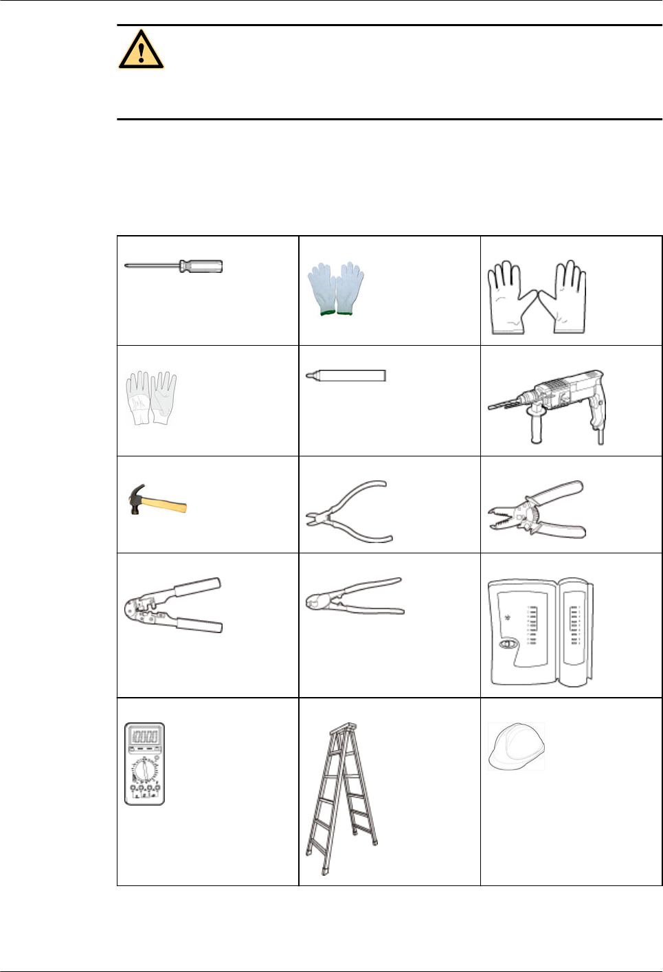
Tool Preparation
To install APs, prepare tools listed in Table 2-1.
Table 2-1 Tools
Phillips screwdriver Protective gloves ESD gloves
Slip-proof glove Marker Hammer drill
Claw hammer Diagonal pliers Wire stripper
RJ45 crimping tool Cable cutter Network cable tester
Multimeter Ladder Safety helmet
AP4050DN-E
Hardware Installation and Maintenance Guide 2 AP Installation
Issue 05 (2018-02-02) Huawei Proprietary and Confidential
Copyright © Huawei Technologies Co., Ltd.
7
Safety belt Anti-skid shoes -
2.2 Installation Flowchart
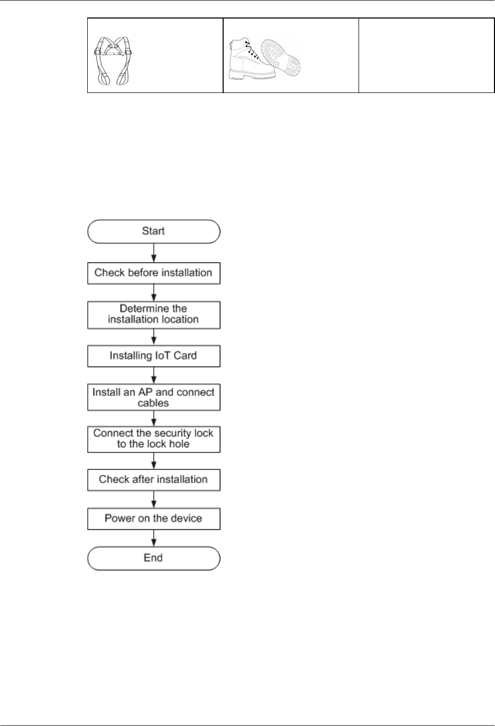
The following figure shows the process for installing an AP.
Figure 2-1 Installation flowchart
2.3 Unpacking the Equipment
Before unpacking the carton, ensure that the packing carton is intact and not damaged or
soaked. Stop unpacking if the equipment is rusted or soggy. Then, investigate causes and
contact the supplier.
After unpacking, check items in the carton against the packing list. If any item is missing,
contact the supplier or agent.
AP4050DN-E
Hardware Installation and Maintenance Guide 2 AP Installation
Issue 05 (2018-02-02) Huawei Proprietary and Confidential
Copyright © Huawei Technologies Co., Ltd.
8
Usually, the packing list contains the following items.
lAP device
lSheet metal mounting bracket
lAdjustable buckle
lExpansion screws
lQuick start guide
lWarranty card
lMAC address label
lSN label
NOTE
If a PoE adapter or a DC power adapter is required, you need to purchase it separately. For DC power adapter
models, see 5.9 Power Adaptation Solution.
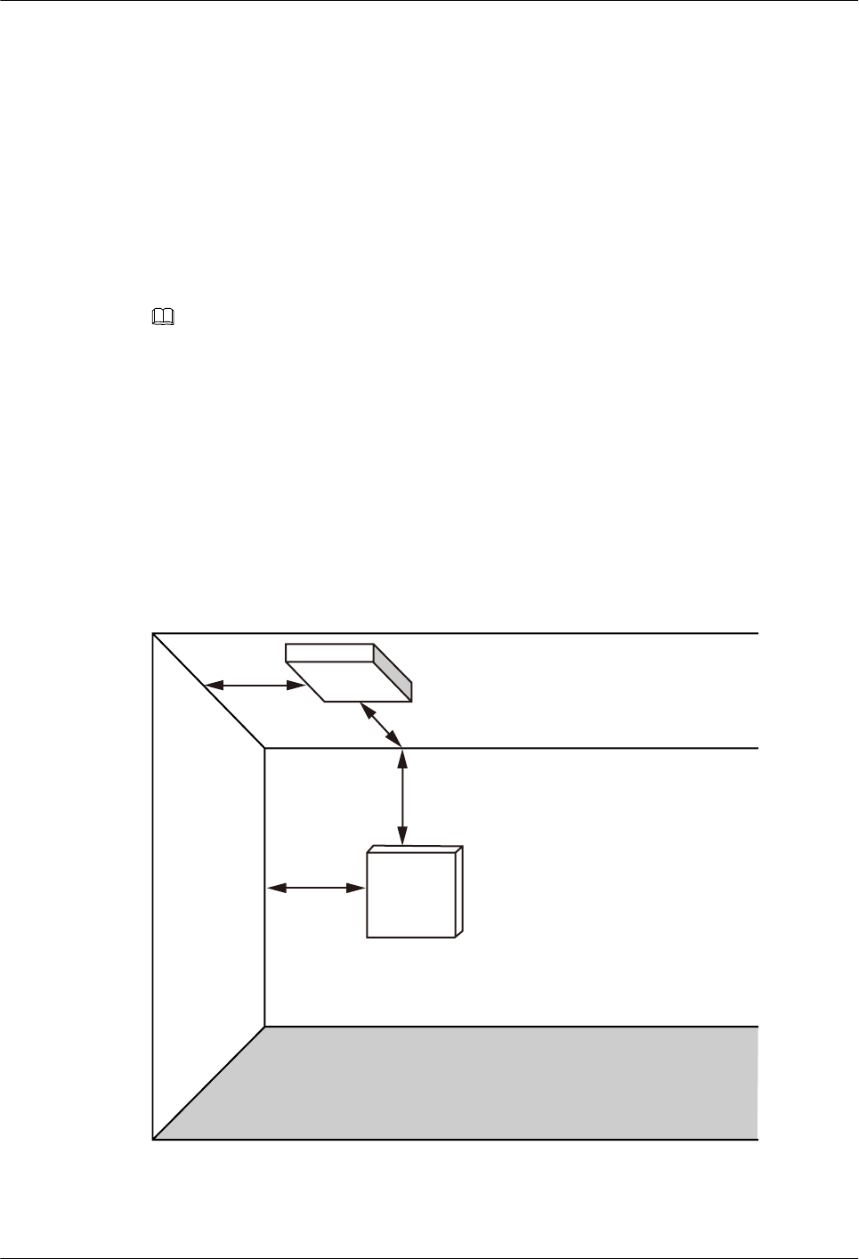
2.4 Determining the Installation Position
Indoor APs are usually mounted on a wall or ceiling using sheet metal mounting brackets.
The installation position is determined by the site survey. There must be at least 200 mm
clearance between the cabling end of the AP and the wall. Figure 2-2 shows space
requirements.
Figure 2-2 Mounting an AP
≥200 mm
≥200 mm
≥200 mm
≥200 mm
Floor
Celling
Wall
When determining the AP installation position, comply with the following rules:
lTry to reduce the number of obstacles, such as walls, between the AP and user terminals.
AP4050DN-E
Hardware Installation and Maintenance Guide 2 AP Installation
Issue 05 (2018-02-02) Huawei Proprietary and Confidential
Copyright © Huawei Technologies Co., Ltd.
9
lPlace the AP far away from electronic devices that may produce radio interference, such
as microwave ovens, other APs, antennas, and other radio communication devices. For
details, see Table 2-2.
lInstall the AP in a hidden position that does not affect daily lives and work of residents.
lInstall the AP in a site that is free from leaking or dripping water, heavy dew, and
humidity, and take protective measures to prevent water from flowing into the equipment
along the cable.
lDo not install the AP in an environment with high temperature, dust, poisonous gases,
flammable or explosive objects, electromagnetic interference (from a radar station, radio
station, or substation), unstable voltage, violent shakes, or strong noise.
Table 2-2 General anti-interference requirements
Scenario Deployment Distance Requirement
Indoor
installation
lThere should be at least a 7 m distance between antennas.
lThe antennas should be placed at least 5 m from the 4G antennas of
the carrier.
lThe antennas should be placed far away from electronic devices that
may produce interference, such as microwave ovens.
NOTE
If antennas are embedded into APs, the deployment distance requirements on the antennas are those on APs.
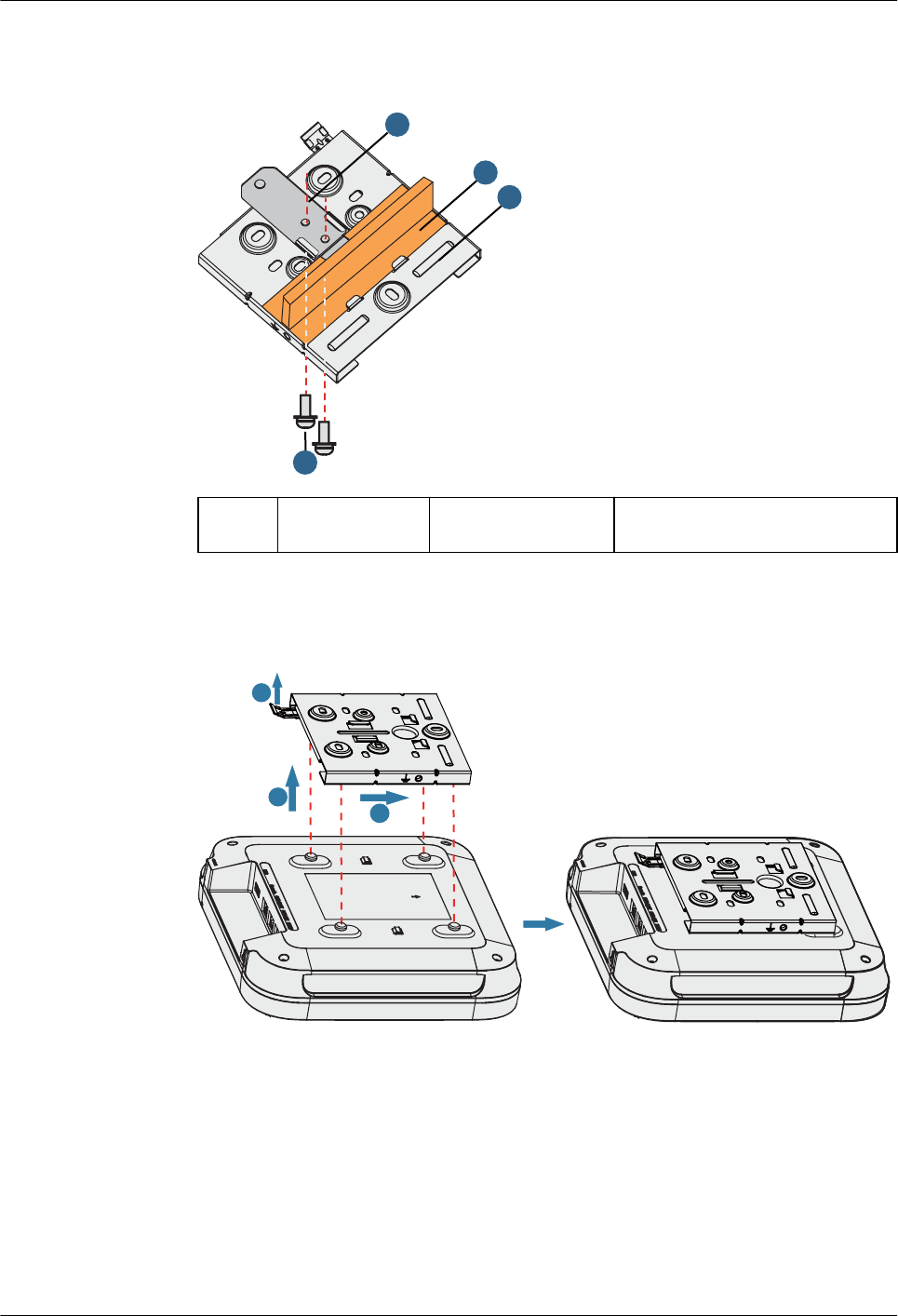
2.5 Installing an IoT Card
An AP4050DN-E has three IoT slots supporting ANT and RFID cards. An ANT card has only
one radio port while an RFID card has two radio ports. Depending on card characteristics, IoT
cards can be installed in one-cable per card or two-cable per card mode. Users need to install
IoT cards onsite as required.
One-Cable per Card
In this mode, one to three ANT or RFID cards can be installed.
1. Remove the front cover of an AP.
AP4050DN-E
Hardware Installation and Maintenance Guide 2 AP Installation
Issue 05 (2018-02-02) Huawei Proprietary and Confidential
Copyright © Huawei Technologies Co., Ltd.
10
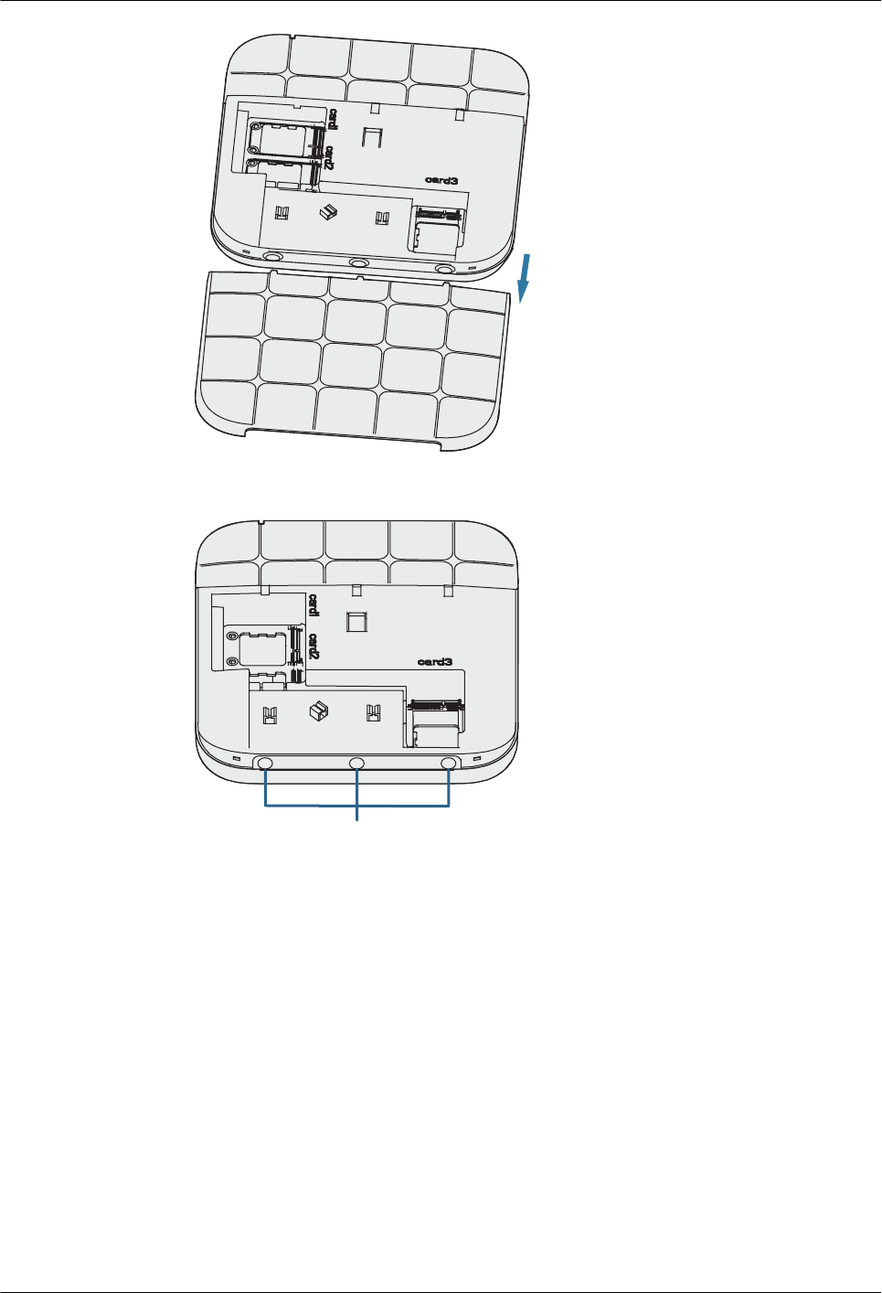
2. Remove rubber plugs based on the number of IoT cards to be installed. One rubber plug
maps one IoT card.
Rubber plugs
3. Place IoT cards in the slots and tighten the cards using M2x7 screws (with a tightening
torque of 1.5 N•m). You are advised to start installation from the card1 slot.
AP4050DN-E
Hardware Installation and Maintenance Guide 2 AP Installation
Issue 05 (2018-02-02) Huawei Proprietary and Confidential
Copyright © Huawei Technologies Co., Ltd.
11
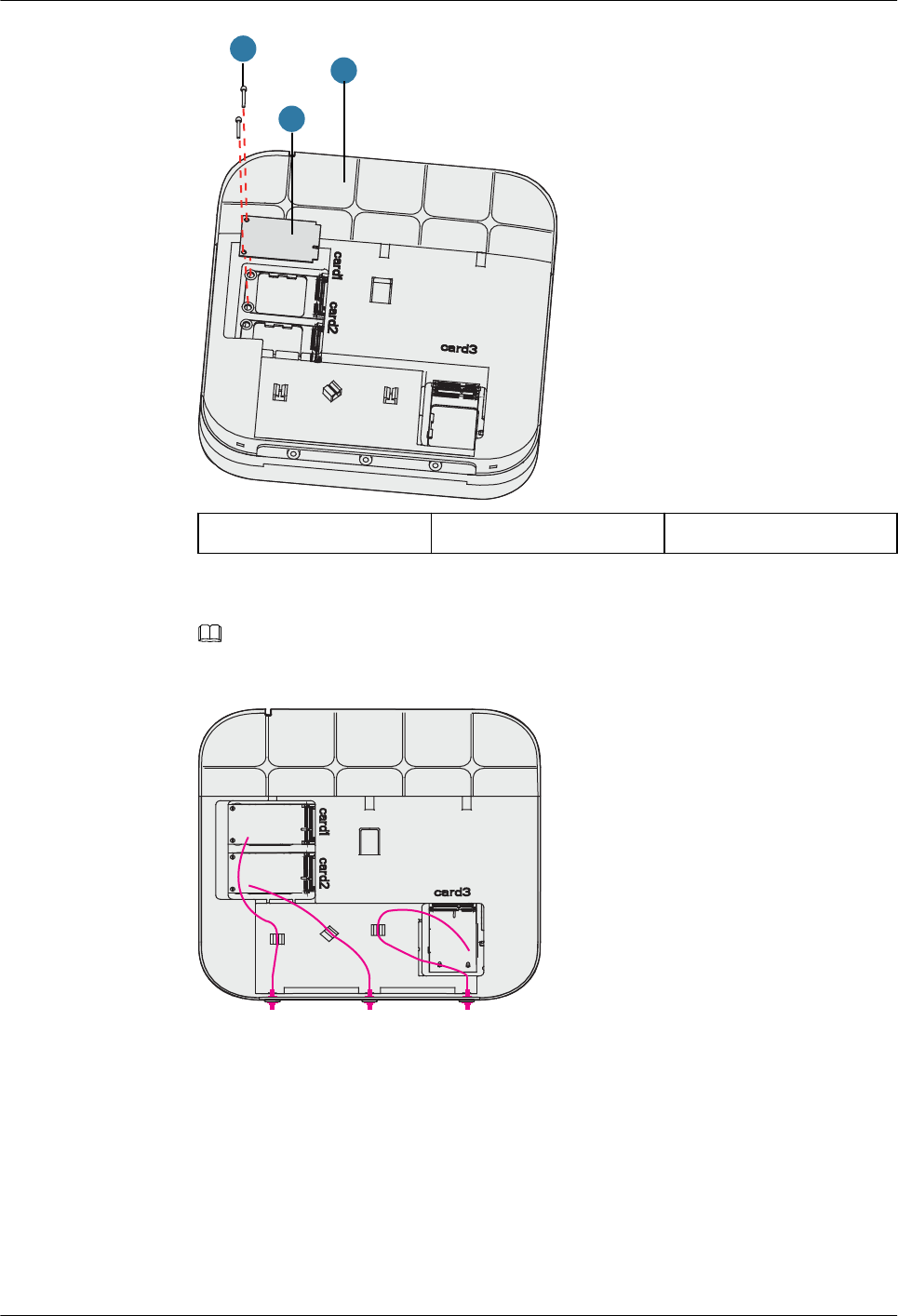
1
2
3
1. AP4050DN-E 2. IoT card 3. M2x7 screws
4. Install RF cables and sort cables following the instruction shown in the figure.
NOTE
lThe diagonal size of a hexagon SMA connector must be less than or equal to 8 mm; otherwise, the
cable cannot be installed.
5. Slide the cover back.
Two-Cable per Card
In this mode, only one RFID card can be installed. The card1 slot is preferentially used.
1. Remove the front cover of an AP.
AP4050DN-E
Hardware Installation and Maintenance Guide 2 AP Installation
Issue 05 (2018-02-02) Huawei Proprietary and Confidential
Copyright © Huawei Technologies Co., Ltd.
12
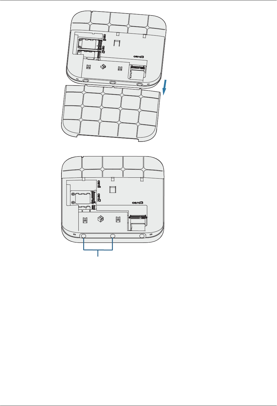
2. Remove the two rubber plugs.
Rubber plugs
3. Place the card in the card1 slot and tighten the card using M2x7 screws (with a
tightening torque of 1.5 N•m).
AP4050DN-E
Hardware Installation and Maintenance Guide 2 AP Installation
Issue 05 (2018-02-02) Huawei Proprietary and Confidential
Copyright © Huawei Technologies Co., Ltd.
13
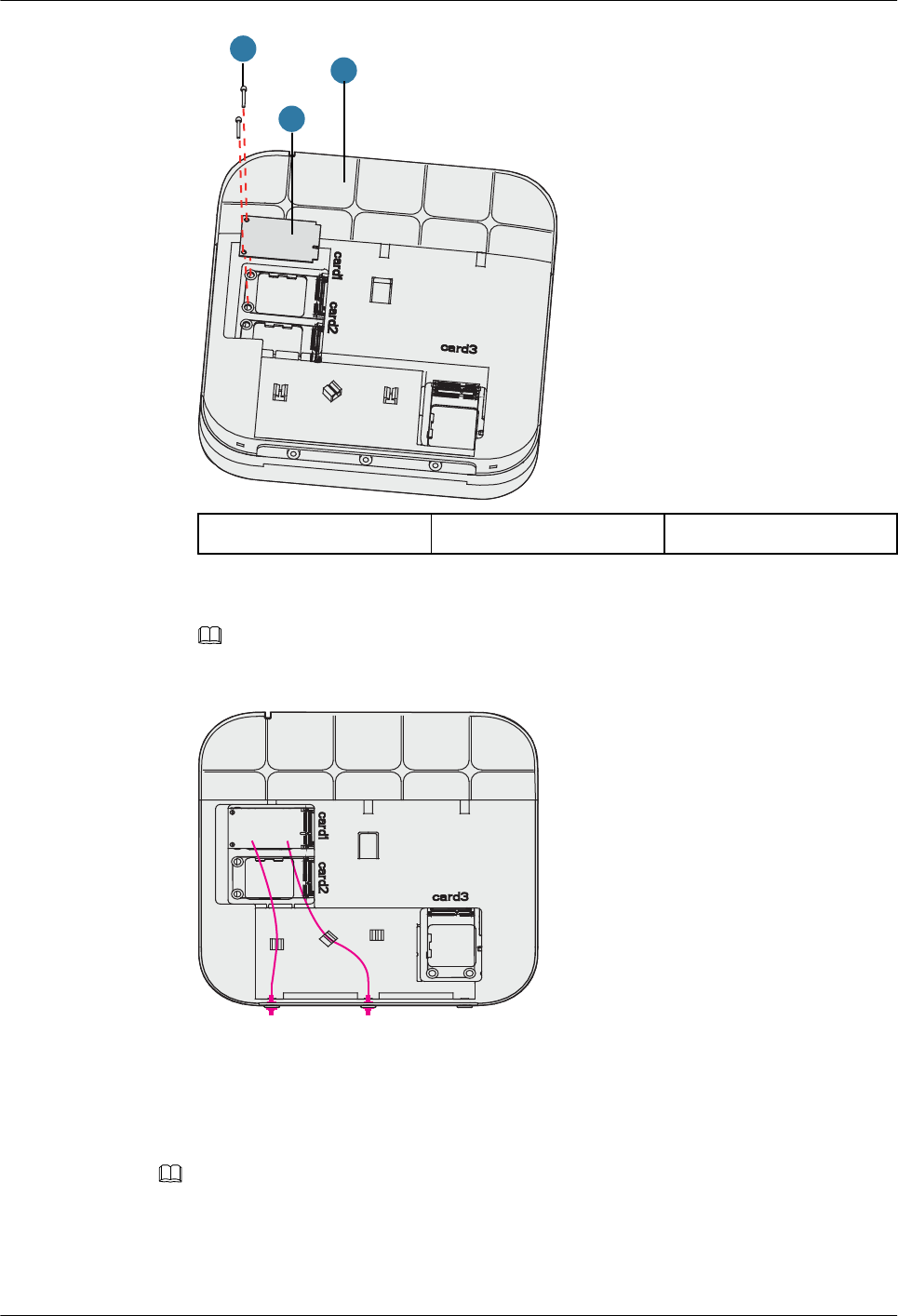
1
2
3
1. AP4050DN-E 2. IoT card 3. M2x7 screws
4. Install RF cables and sort cables following the instruction shown in the figure.
NOTE
lThe diagonal size of a hexagon SMA connector must be less than or equal to 8 mm; otherwise, the
cable cannot be installed.
5. Slide the cover back.
2.6 Installing the AP
NOTE
Remove the protective film on the surface before installation to prevent electrostatic discharge.
2.6.1 Installing the Device on a Wall
AP4050DN-E
Hardware Installation and Maintenance Guide 2 AP Installation
Issue 05 (2018-02-02) Huawei Proprietary and Confidential
Copyright © Huawei Technologies Co., Ltd.
14
NOTE
A wall for installing the device needs to meet the following requirements:
lThe wall can bear the weight of four times the total weight of the device and mounting bracket
without damage.
lWhen the tightening torx of a screw reaches 5 N•m, the screw still properly works, without crack
or damage on the wall.
Mounting kits and expansion bolts are required to install the AP on a wall. The procedures are
as follows:
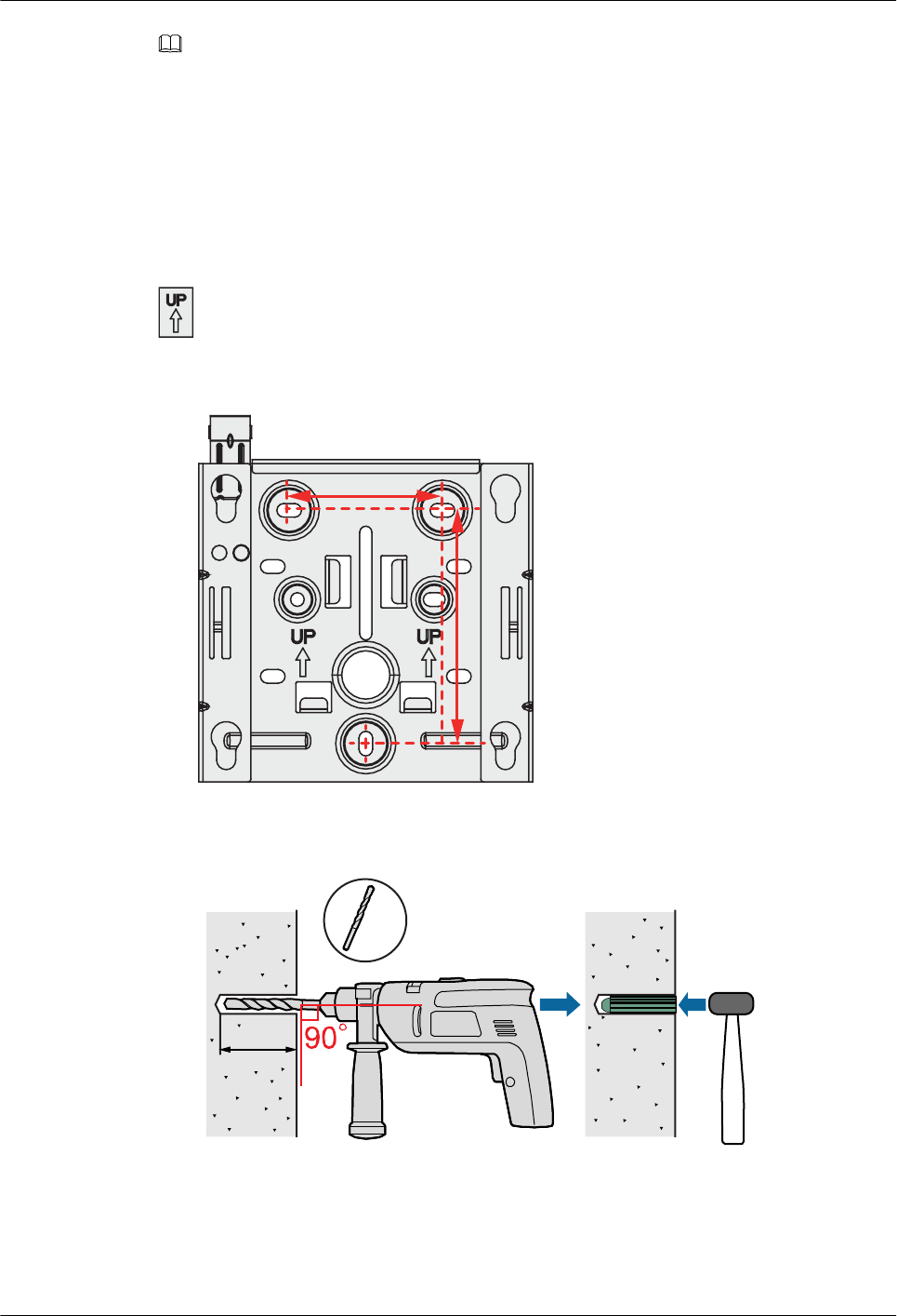
When fixing the sheet metal mounting bracket, ensure that the arrows point upwards on the
label.
1. Fix a mounting bracket to the wall against the wall and mark the drilling positions
through holes of the bracket.
59 mm
85 mm
2. Use a 6 mm drill bit to drill 25 mm to 30 mm deep holes in the drilling positions.
Hammer the expansion tubes into the holes until the expansion tubes are completely
embedded into the wall.
25 mm~30 mm
Ø6
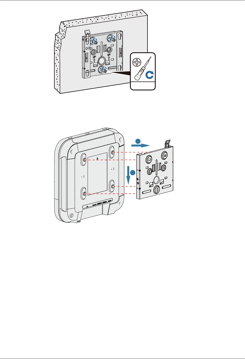
3. Fix the mounting bracket to the wall and use the Phillips screwdriver to fasten three
expansion screws into the expansion tubes.
AP4050DN-E
Hardware Installation and Maintenance Guide 2 AP Installation
Issue 05 (2018-02-02) Huawei Proprietary and Confidential
Copyright © Huawei Technologies Co., Ltd.
15
1.7 N•m
ST3.5
4. Connect the cables. For details, see 2.7 Cable Connection.
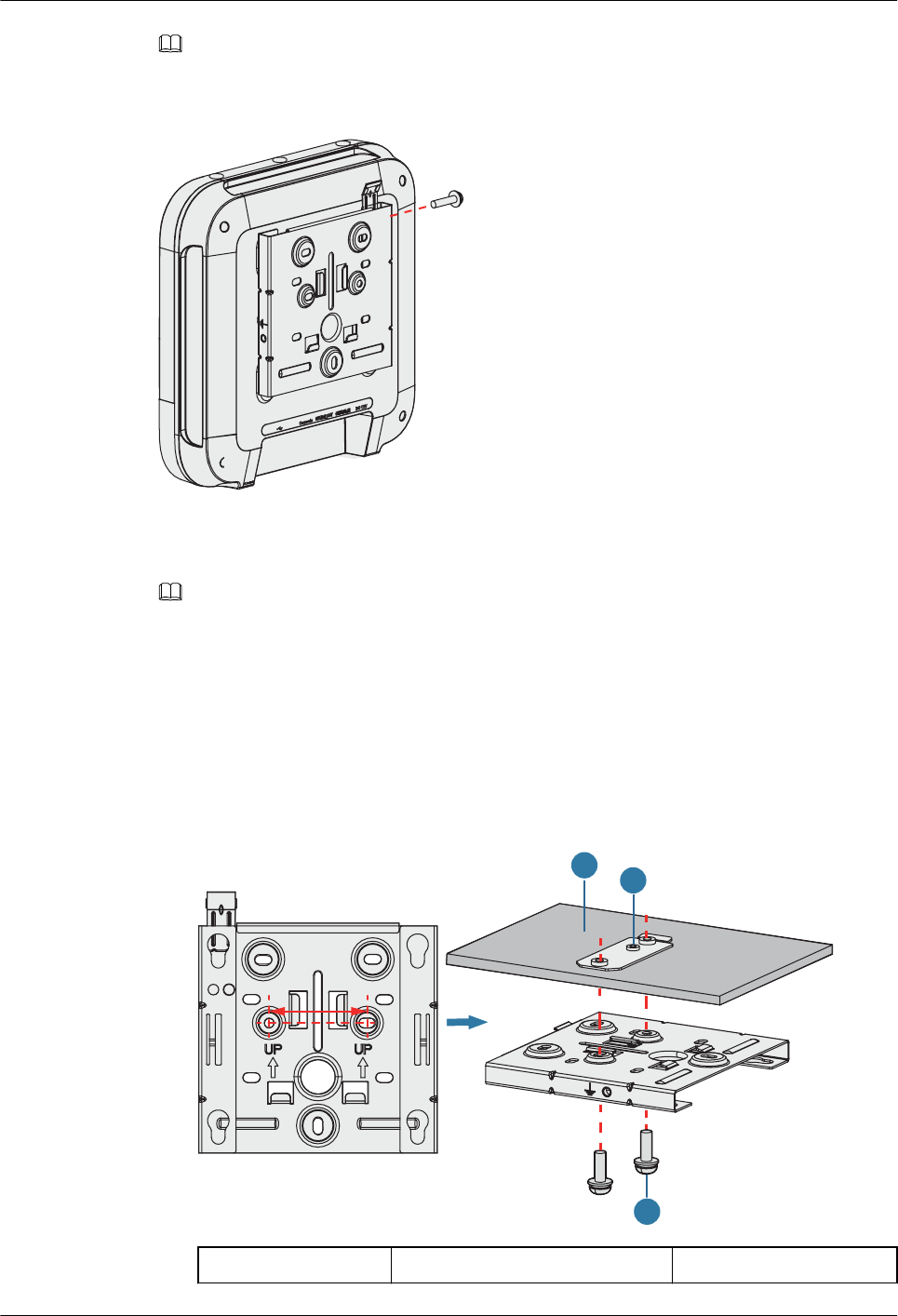
5. Align the rubber feet of the device over the mounting slots on the mounting bracket and
vertically push the AP to secure it. When the spring clip is popped up, push the AP
downward until it snaps into place (you can hear a click).
a
b
AP4050DN-E
Hardware Installation and Maintenance Guide 2 AP Installation
Issue 05 (2018-02-02) Huawei Proprietary and Confidential
Copyright © Huawei Technologies Co., Ltd.
16
NOTE
In a scenario with heavy vibrations, tighten the AP to the mounting bracket using M4x30 screws with a
torque of 1.4N•m. This prevents the AP falling off from due to vibrations. In normal scenarios, you do not
need to install these screws.
2.6.2 Installing the Device on a Ceiling
NOTE
A ceiling needs to bear the weight of four times the total weight of the device and mounting bracket
without damage.
1. Remove a ceiling tile, determine locations of mounting holes based on the distance
between two installation holes on the mounting bracket, use a hammer drill to drill holes
on the ceiling tile, and fix the mounting bracket to the ceiling tile(with a tightening
torque of 1.4 N•m).
The screws provided for ceiling-mounting of APs are 30 mm long and can be used to fix
an AP on a ceiling no thicker than 15 mm. To install APs on thicker ceilings, you need to
purchase longer screws.
47 mm
1
3
2
1. Ceiling tile 2. Adjustable buckle 3. M4x30 screw
AP4050DN-E
Hardware Installation and Maintenance Guide 2 AP Installation
Issue 05 (2018-02-02) Huawei Proprietary and Confidential
Copyright © Huawei Technologies Co., Ltd.
17
2. Connect the cables. For details, see 2.7 Cable Connection.
3. Align the rubber feet of the device over the mounting slots on the mounting bracket and
vertically push the AP to secure it. When the spring clip is popped up, push the AP
horizontally until it snaps into place (you can hear a click).
b
c
a
NOTE
lEnsure that the AP is correctly installed on the mounting bracket and there is 200 mm space above
and around the AP for maintenance.
lIn a scenario with heavy vibrations, tighten the AP to the mounting bracket using M4x30 screws
with a torque of 1.4N•m. This prevents the AP falling off from due to vibrations. In normal
scenarios, you do not need to install these screws.
2.6.3 Installing the Device on a T-rail
A T-rail needs to bear the weight of four times the total weight of the device and mounting
bracket without damage. Figure 2-3 shows the T-rail dimensions requirements (t: thickness;
w: width).
Figure 2-3 Section of a T-rail
19 mm ≤ w ≤ 29 mm
0.6 mm ≤ t ≤ 1.0 mm
AP4050DN-E
Hardware Installation and Maintenance Guide 2 AP Installation
Issue 05 (2018-02-02) Huawei Proprietary and Confidential
Copyright © Huawei Technologies Co., Ltd.
18
1. Remove two ceiling tiles around the T-rail, use screws to fix the adjustable buckle to the
mounting bracket, hook the adjustable buckle to the T-rail, and secure the screw on the
adjustable buckle to fasten the mounting bracket and T-rail.
2
3
1
4
1. T-rail 2. M4x30 Screw 3. Adjustable buckle 4. Sheet metal mounting bracket
2. Connect the cables. For details, see 2.7 Cable Connection.
3. Align the rubber feet of the device over the mounting slots on the mounting bracket and
vertically push the AP to secure it. When the spring clip is popped up, push the AP
horizontally until it snaps into place (you can hear a click).
b
c
a
AP4050DN-E
Hardware Installation and Maintenance Guide 2 AP Installation
Issue 05 (2018-02-02) Huawei Proprietary and Confidential
Copyright © Huawei Technologies Co., Ltd.
19

NOTE
lBefore fixing the adjustable buckle with a screw, adjust the buckle to a proper position based on the
T-rail width.
lEnsure that the AP is correctly installed on the mounting bracket and there is 200 mm space above
and around the AP for maintenance.
lIn a scenario with heavy vibrations, tighten the AP to the mounting bracket using M4x30 screws
with a torque of 1.4N•m. This prevents the AP falling off from due to vibrations. In normal
scenarios, you do not need to install these screws.
2.6.4 Removing an AP
Flip the spring clip on the mounting bracket and slip the AP towards the spring clip. Release
the spring clip until the rubber feet of the AP enter the mounting keyholes. Remove the AP
from the mounting bracket.
Figure 2-4 Removing an AP
a
b
c
NOTE
If a captive screw is installed, remove the screw and then follow the preceding steps to uninstall the AP.
2.7 Cable Connection
Table 2-3 describes the cable connections.
AP4050DN-E
Hardware Installation and Maintenance Guide 2 AP Installation
Issue 05 (2018-02-02) Huawei Proprietary and Confidential
Copyright © Huawei Technologies Co., Ltd.
20
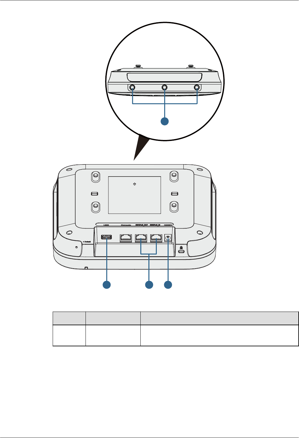
Figure 2-5 Appearance of the AP4050DN-E
3
1 2
4
Table 2-3 Cable connections
No. Cable or Device Description
1 USB flash drive Connects to a USB flash drive to extend the storage space
of the AP, and provides a maximum of 2.5 W power.
AP4050DN-E
Hardware Installation and Maintenance Guide 2 AP Installation
Issue 05 (2018-02-02) Huawei Proprietary and Confidential
Copyright © Huawei Technologies Co., Ltd.
21
No. Cable or Device Description
2 Network cable lThe service network cable and PoE input cable cannot
be connected to the console port. Otherwise, the AP
may be damaged when using PoE power supply.
lIf the AP needs to connect to the Ethernet, ensure that
the Ethernet cable is working properly. If the Ethernet
cable is not working properly, for example, RJ45
connectors are short-circuited, the AP may fail to be
powered on or fail to work. Before connecting an
Ethernet cable to the AP, use the cable test tool to
check whether the cable is qualified. If the cable is
unqualified, replace it.
NOTICE
lDo not insert a PoE input cable into the GE1/PoE_OUT port.
lCAT5e cables or higher must be used.
lThe length of a cable in the GE0/PoE_IN interface cannot
exceed 100 m.
lThe length of a cable cannot exceed 40 m when the GE1/
PoE_OUT port has PoE output and cannot exceed 100 m
when there is no PoE output.
lThe GE1/PoE_OUT port of an AP can provide power output
only works in 802.3at PoE mode. The output power varies at
different connection status:
lThe maximum output power is 7 W when no IoT card is
connected to the AP and the USB port is not used.
lThe maximum output power is 5.5 W when only one IoT
card is connected to the AP and the USB port is not used.
lThe PoE_OUT function is automatically disabled when
two or more IoT cards are connected to the AP or the
USB port is used.
3DC power adapter When the AP uses the DC power supply, use a power
adapter for power supply; otherwise, the AP may be
damaged.
4 RF cable Connects to an IoT card or an antenna.
NOTE
The AP is powered by either the DC power supply or PoE power supply that backs up each other.
When installing a cable, you must make a drip loop to prevent water from flowing into
devices along the cable. For the method of making the drip loop, see 5.8 Guide to Making
Drip Loops.
Pay attention to the following points when bundling the cables:
lDifferent types of cables must be separately routed with the minimum spacing of 30 mm
and cannot be entangled or crossed. Cables should be parallel or separated using
dedicated separators.
lBundled cables are closely arranged, straight, tidy, and undamaged.
AP4050DN-E
Hardware Installation and Maintenance Guide 2 AP Installation
Issue 05 (2018-02-02) Huawei Proprietary and Confidential
Copyright © Huawei Technologies Co., Ltd.
22
lCable ties are bound neatly facing the same direction, and those at the same horizontal
line must be in a straight line. Cable tie tails should be cut smoothly and evenly.
lLabels or nameplates must be attached to the cables after they are installed.
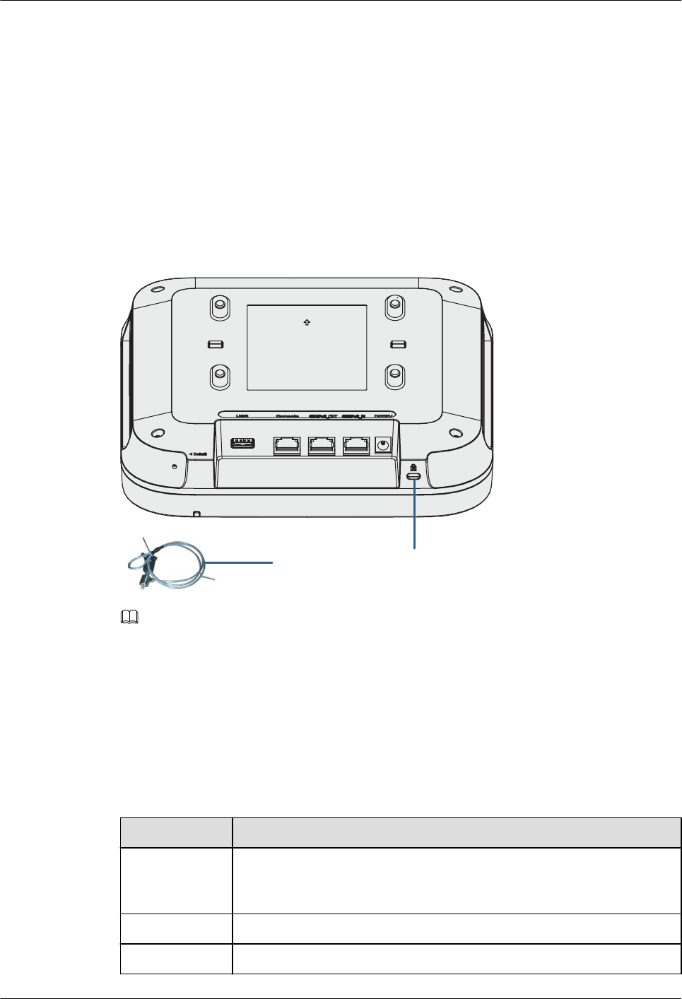
2.8 Connecting the Security Lock
There is a security slot on the device. You can lock the device to an immovable object to
prevent theft. The detailed procedures are as follows:
1. Fasten the cable of the security lock to an immovable object around.
2. Insert the security lock into the security slot and lock it.
Lock hole
Security lock
NOTE
You need to purchase the security lock separately.
2.9 Checking the Device After Installation
Table 2-4 shows the items to be checked after installation is complete. For more details, see
Installation Checklist in the appendix.
Table 2-4 Installation checklist
No. Check Item
1 The device is installed by strictly following the design draft. The
installation position meets space requirements, with maintenance space
reserved.
2 The device is securely installed.
3 The power cables are intact and not spliced.
AP4050DN-E
Hardware Installation and Maintenance Guide 2 AP Installation
Issue 05 (2018-02-02) Huawei Proprietary and Confidential
Copyright © Huawei Technologies Co., Ltd.
23

No. Check Item
4 Terminals of the power cables are welded or cramped firmly.
5 All power cables are not short-circuited or reversely connected and must
be intact with no damage.
6 The power cables and ground cables are separated from other cables and
bundled separately.
7 Connectors of signal cables are complete, intact, and tightly connected.
The signal cables are not damaged or broken.
8 Labels on cables are clear and correct.
2.10 Powering on the AP
After the AP is powered on, observe the indicator on the AP to check the system running
status. For details, see 1.2 Indicator Description.
NOTE
Do not frequently power on and off the device.
AP4050DN-E
Hardware Installation and Maintenance Guide 2 AP Installation
Issue 05 (2018-02-02) Huawei Proprietary and Confidential
Copyright © Huawei Technologies Co., Ltd.
24

3 Logging In to the Device
About This Chapter
3.1 Logging In to the Device Using STelnet/Telnet
3.2 Logging In to the Device Through the Web System
3.3 Logging In to the Device Through the Console Port
3.1 Logging In to the Device Using STelnet/Telnet
You can log in to the device using STelnet V2 or Telnet to configure, manage, and maintain
the device in the CLI.
NOTE
lBy default, only the STelnet V2 service is enabled on the device.
lTelnet has security vulnerabilities. You are not advised to enable the Telnet service.
Device connections are classified into wired and wireless connections.
lIn versions earlier than V200R007C20, APs support wired connections.
lIn V200R007C20 and later, Fat APs support both wired and wireless connections, and
Fit APs and cloud APs support wired connections.
Before logging in to the device, complete the following tasks:
lPower on the device.
lPrepare network cables used to connect device interfaces for wired connections. No
network cable is required for wireless connections.
The following table lists the default configuration of the device. You are advised to change the
default user name and password on your first login.
AP4050DN-E
Hardware Installation and Maintenance Guide 3 Logging In to the Device
Issue 05 (2018-02-02) Huawei Proprietary and Confidential
Copyright © Huawei Technologies Co., Ltd.
25
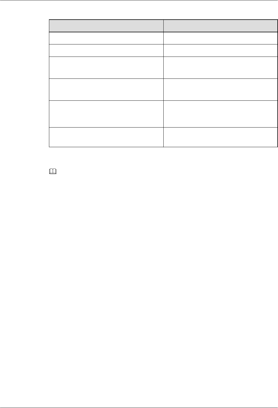
Table 3-1 Default configuration of the device
Parameter Default Setting
User name admin
Password admin@huawei.com
IP address lWired connection: 169.254.1.1
lWireless connection: 192.168.1.1
Subnet mask lWired connection: 255.255.0.0
lWireless connection: 255.255.255.0
SSID HUAWEI-XXXX, applicable to wireless
connections of Fat APs (XXXX specifies the
last four bits of the AP's MAC address.)
Wireless password None, applicable to wireless connections of
Fat APs
NOTE
For a Fit AP and cloud AP, you can perform the following operations:
lIf the Fit AP is already online on the AC, you can remotely log in to the AC on a local terminal and run
the display ap all command to check the IP address of the device.
lIf the Fit AP in any version is offline or the Fit AP in V200R007C10 or later does not go online, you can
access the device through the offline management VAP for operations. By default, the SSID of the offline
management VAP is hw_manage_xxxx (xxxx specifies the last four bits of the AP's MAC address) and
the password is hw_manage. After the IP address of the PC is set to 169.254.2.x/24 (169.254.2.1
excluded and 169.254.2.100 recommended), the connection is set up, you can log in to the AP using
STelnet for operations.
lIf the cloud AP is offline or does not go online, you can access the device through the offline management
VAP for operations. By default, the SSID of the offline management VAP is hw_manage_xxxx (xxxx
specifies the last four bits of the AP's MAC address) and the password is hw_manage. After the PC
dynamically obtains an IP address and connects to the AP, you can log in to the AP using STelnet for
operations.
The following example uses the default parameters and is used for reference only.
Wired Connection Mode
Step 1 Use a network cable to connect a PC to any network port of the AP or that of the switch on
the same network segment as the AP.
Step 2 Assign the PC with an IP address on the same network segment as the default IP address of
the device so that the PC and device are reachable to each other.
If the device uses the default settings, the IP address of the PC must be in the network
segment 169.254.0.0/16 but cannot be 169.254.1.1. 169.254.1.100 is recommended.
Step 3 Start the CLI on the PC and access the IP address 169.254.1.1 of the device using STelnet V2.
Step 4 Enter the user name and password as prompted to log in to the user interface.
----End
AP4050DN-E
Hardware Installation and Maintenance Guide 3 Logging In to the Device
Issue 05 (2018-02-02) Huawei Proprietary and Confidential
Copyright © Huawei Technologies Co., Ltd.
26

Wireless Connection Mode
Step 1 By default, STAs search for the WLAN HUAWEI-XXXX within the wireless signal coverage
of a Fat AP. STAs can access the WLAN without entering the password. If the SSID and
password have been configured, use the specified SSID and password to set up a wireless
connection.
Step 2 Start the CLI on the STA and access the IP address 192.168.1.1 of the device using STelnet
V2.
Step 3 Enter the user name and password as prompted to log in to the user interface.
----End
Method of Obtaining Upgrade and Configuration Documentation
To perform subsequent upgrades and configurations after login to the device, visit Huawei
enterprise technical support website http://support.huawei.com/enterprise and search for
product documentation by keyword. The search method is described as follows:
lFit AP:
–Upgrade: Search for Fit AP upgrade guide, and refer to the upgrade guide in the
documentation of the correct version.
–Configuration: Search for AC6605 product documentation, and refer to the
configuration guide in the documentation of the correct version.
lFat AP:
–Upgrade: Search for Fat AP upgrade guide, and refer to the upgrade guide in the
documentation of the correct version.
–Configuration: Search for Fat AP product documentation, and refer to the
configuration guide in the documentation of the correct version.
lcloud AP:
–Upgrade: Search for cloud AP upgrade guide, and refer to the upgrade guide in the
documentation of the correct version.
–Online configuration: Search for cloud AP product documentation, and refer to
the configuration guide in the documentation of the correct version.
–Service configuration after APs go online: Search for CloudCampus solution
product documentation, and refer to the deployment guide in the documentation
of the correct version.
3.2 Logging In to the Device Through the Web System
The built-in web system allows you to use a browser to log in to the device. You can
configure, manage, and maintain a Fat AP and cloud AP on the GUI. On the web page, you
are prompted to configure and manage a Fit AP on the AC.
Device connections are classified into wired and wireless connections.
lIn versions earlier than V200R007C20, APs support wired connections.
lIn V200R007C20 and later, Fat APs support both wired and wireless connections, and
Fit APs and cloud APs support wired connections.
AP4050DN-E
Hardware Installation and Maintenance Guide 3 Logging In to the Device
Issue 05 (2018-02-02) Huawei Proprietary and Confidential
Copyright © Huawei Technologies Co., Ltd.
27
Before logging in to the device, complete the following tasks:
lPower on the device.
lPrepare network cables used to connect device interfaces for wired connections. No
network cable is required for wireless connections.
The following table lists the default configuration of the device. You are advised to change the
default user name and password on your first login.
Table 3-2 Default configuration of the device
Parameter Default Setting
User name admin
Password admin@huawei.com
IP address lWired connection: 169.254.1.1
lWireless connection: 192.168.1.1
Subnet mask lWired connection: 255.255.0.0
lWireless connection: 255.255.255.0
SSID HUAWEI-XXXX, applicable to wireless
connections of Fat APs (XXXX specifies the
last four bits of the AP's MAC address.)
Wireless password None, applicable to wireless connections of
Fat APs
NOTE
For a Fit AP and cloud AP, you can perform the following operations:
lIf the Fit AP in any version is offline or the Fit AP in V200R007C10 or later does not go online, you can
access the device through the offline management VAP for operations. By default, the SSID of the offline
management VAP is hw_manage_xxxx (xxxx specifies the last four bits of the AP's MAC address) and
the password is hw_manage. After the IP address of the PC is set to 169.254.2.x/24 (169.254.2.1
excluded and 169.254.2.100 recommended), the connection is set up, , and you can log in to the AP using
web system for operations.
lIf the cloud AP is offline or does not go online, you can access the device through the offline management
VAP for operations. By default, the SSID of the offline management VAP is hw_manage_xxxx (xxxx
specifies the last four bits of the AP's MAC address) and the password is hw_manage. After the PC
dynamically obtains an IP address and connects to the AP, you can log in to the AP using web system for
operations.
The following example uses the default parameters and is used for reference only.
Wired Connection Mode
Step 1 Use a network cable to connect a PC to any network port of the AP or that of the switch on
the same network segment as the AP.
Step 2 Assign the PC with an IP address on the same network segment as the default IP address of
the device so that the PC and device are reachable to each other.
AP4050DN-E
Hardware Installation and Maintenance Guide 3 Logging In to the Device
Issue 05 (2018-02-02) Huawei Proprietary and Confidential
Copyright © Huawei Technologies Co., Ltd.
28

If the device uses the default settings, the IP address of the PC must be in the network
segment 169.254.0.0/16 but cannot be 169.254.1.1. 169.254.1.100 is recommended.
Step 3 Open the browser on the PC, enter http://IP address in the address box, and press Enter to
log in. Select a language for the web system, enter the default user name and password, and
click Login to enter the web system home page.
----End
Wireless Connection Mode
Step 1 By default, STAs search for the WLAN HUAWEI-XXXX within the wireless signal coverage
of a Fat AP. STAs can access the WLAN without entering the password. If the SSID and
password have been configured, use the specified SSID and password to set up a wireless
connection.
Step 2 Open the browser on the STA, enter http://IP address in the address box, and press Enter to
log in. Select a language for the web system, enter the default user name and password, and
click Login. The web system home page is displayed.
----End
Method of Obtaining Upgrade and Configuration Documentation
To perform subsequent upgrades and configurations after login to the device, visit Huawei
enterprise technical support website http://support.huawei.com/enterprise and search for
product documentation by keyword. The search method is described as follows:
lFit AP:
–Upgrade: Search for Fit AP upgrade guide, and refer to the upgrade guide in the
documentation of the correct version.
–Configuration: Search for AC6605 product documentation, and refer to the
configuration guide in the documentation of the correct version.
lFat AP:
–Upgrade: Search for Fat AP upgrade guide, and refer to the upgrade guide in the
documentation of the correct version.
–Configuration: Search for Fat AP product documentation, and refer to the
configuration guide in the documentation of the correct version.
lcloud AP:
–Upgrade: Search for cloud AP upgrade guide, and refer to the upgrade guide in the
documentation of the correct version.
–Online configuration: Search for cloud AP product documentation, and refer to
the configuration guide in the documentation of the correct version.
–Service configuration after APs go online: Search for CloudCampus solution
product documentation, and refer to the deployment guide in the documentation
of the correct version.
3.3 Logging In to the Device Through the Console Port
Before logging in to the device, complete the following tasks:
AP4050DN-E
Hardware Installation and Maintenance Guide 3 Logging In to the Device
Issue 05 (2018-02-02) Huawei Proprietary and Confidential
Copyright © Huawei Technologies Co., Ltd.
29

lPower on the device.
lPrepare a console cable.
lPrepare terminal simulation software.
NOTE
If your PC's operating system provides terminal simulation software (like HyperTerminal in Windows 2000/
XP), you do not need to install additional terminal simulation software. If the PC runs on an operating system
without terminal simulation software (like Windows 7), install third-party terminal simulation software on the
PC by referring to the user manual or online help.
Step 1 Use a console cable to connect the PC to the console port of the device.
Step 2 Start terminal emulation software on the PC, create a connection, and set communication
parameters as follows:
lBaud rate (B): 9600
lData bits (D): 8
lParity (P): None
lStop bits (S): 1
lFlow control (F): None
Step 3 Press Enter and enter the authentication information as prompted to log in to the user view.
(The following information is only for reference.)
For a Fit AP, enter the default user name admin and password admin@huawei.com.
You are advised to change the default user name and password on your first login.
Login authentication
Username: admin
Password:
Info: You are advised to change the password to ensure security.
For a Fat AP and Cloud AP, set a passowrd of console, and use the password to log in.
Please configure the login password:
Info: A plain text password is a string of 8 to 16 case-sensitive characters and
must be a combination of at least two of the follow
ing: uppercase letters A to Z, lowercase letters a to z, digits, and special
characters. A cipher text password contains 56 or 68 ch
aracters.
Enter password:
Confirm password:
----End
Method of Obtaining Upgrade and Configuration Documentation
To perform subsequent upgrades and configurations after login to the device, visit Huawei
enterprise technical support website http://support.huawei.com/enterprise and search for
product documentation by keyword. The search method is described as follows:
lFit AP:
–Upgrade: Search for Fit AP upgrade guide, and refer to the upgrade guide in the
documentation of the correct version.
–Configuration: Search for AC6605 product documentation, and refer to the
configuration guide in the documentation of the correct version.
AP4050DN-E
Hardware Installation and Maintenance Guide 3 Logging In to the Device
Issue 05 (2018-02-02) Huawei Proprietary and Confidential
Copyright © Huawei Technologies Co., Ltd.
30

lFat AP:
–Upgrade: Search for Fat AP upgrade guide, and refer to the upgrade guide in the
documentation of the correct version.
–Configuration: Search for Fat AP product documentation, and refer to the
configuration guide in the documentation of the correct version.
lcloud AP:
–Upgrade: Search for cloud AP upgrade guide, and refer to the upgrade guide in the
documentation of the correct version.
–Online configuration: Search for cloud AP product documentation, and refer to
the configuration guide in the documentation of the correct version.
–Service configuration after APs go online: Search for CloudCampus solution
product documentation, and refer to the deployment guide in the documentation
of the correct version.
AP4050DN-E
Hardware Installation and Maintenance Guide 3 Logging In to the Device
Issue 05 (2018-02-02) Huawei Proprietary and Confidential
Copyright © Huawei Technologies Co., Ltd.
31
4 Hardware Failures
About This Chapter
This section describes common methods for troubleshooting typical hardware faults.
4.1 A Device Fails to Be Powered On
4.1 A Device Fails to Be Powered On
Fault Description
The SYS indicator of a device is off.
Possible Causes
Power Supply Mode Possible Cause
Power supply using a power module lThe device is powered off.
lThe power cable is not securely
connected to the device.
lThe power supply unit has failed.
–If the device connects to an external
power source, its power adapter may
fail.
–If the device has a built-in power
supply, the device itself may be
faulty.
AP4050DN-E
Hardware Installation and Maintenance Guide 4 Hardware Failures
Issue 05 (2018-02-02) Huawei Proprietary and Confidential
Copyright © Huawei Technologies Co., Ltd.
32
Power Supply Mode Possible Cause
PoE power supply lThe power sourcing equipment does not
support the PoE function or is faulty.
lThe power sourcing equipment does not
support the required power supply mode.
lThe power sourcing equipment does not
provide sufficient power.
lThe power sourcing equipment is
incorrectly configured (the PoE function
is disabled or the power-off time range is
improperly set).
lThe line is faulty (the network cable or
distribution frame is damaged).
lThe device is faulty.
Troubleshooting Procedure
Power Supply Mode Troubleshooting Procedure
Power supply using a power module 1. Check whether the device is powered
off.
2. Check that the power cable is securely
connected to the device.
3. Check whether the power supply is
normal.
Replace the power adapter with a normal
one. If the device is powered on, the
original power adapter is faulty. Contact
technical support personnel or Huawei
agent and ask them to replace the power
adapter.
4. If the device still cannot be powered on,
the device itself is faulty. Contact
technical support personnel or Huawei
agent and ask them to replace the device.
AP4050DN-E
Hardware Installation and Maintenance Guide 4 Hardware Failures
Issue 05 (2018-02-02) Huawei Proprietary and Confidential
Copyright © Huawei Technologies Co., Ltd.
33
Power Supply Mode Troubleshooting Procedure
PoE power supply 1. Check whether the power sourcing
equipment supports PoE or is faulty.
2. Check whether the power output mode
of the power sourcing equipment is
supported by the powered device.
3. Check whether the power sourcing
equipment can support the maximum
power consumption of the device.
4. Check whether the configuration on the
power sourcing equipment causes PoE
power supply errors, such as the PoE
function is disabled or the power-off
time range is incorrectly set.
5. Check whether the network cable or
distribution frame is faulty.
6. If the device still cannot be powered on,
the device itself is faulty. Contact
technical support personnel or Huawei
agent and ask them to replace the device.
NOTE
The output power of an 802.3af PSE port is 15.4 W, that of an 802.3at PSE port is 30 W, and that of an
802.3bt PSE port is 60 W.
AP4050DN-E
Hardware Installation and Maintenance Guide 4 Hardware Failures
Issue 05 (2018-02-02) Huawei Proprietary and Confidential
Copyright © Huawei Technologies Co., Ltd.
34

5 Appendix
About This Chapter
5.1 On-site Cable Assembly and Installation
5.2 Environmental Requirements for Device Operation
5.3 Equipment Grounding Specifications
5.4 Engineering Labels for Cables
5.5 Guide to Using Optical Modules
5.6 Fault Tag
5.7 Installation Checklist
5.8 Guide to Making Drip Loops
5.9 Power Adaptation Solution
5.1 On-site Cable Assembly and Installation
5.1.1 Cable Assembly Precautions
Checking the Appearance of Cables
lIf the cable jacket or insulation is visibly dirty, clean it before assembly.
lIf the jacket or insulation of a cable has visible damage, irreparable scuffing, or other
defects, do not use the cable.
lIf the shield layer of a cable is damaged, do not use the cable.
lIf the cable jacket or insulation cracks after the cable is bent or twisted, discard this cable
and check whether other cables have the same problem. If other cables have the same
problem, replace these cables.
AP4050DN-E
Hardware Installation and Maintenance Guide 5 Appendix
Issue 05 (2018-02-02) Huawei Proprietary and Confidential
Copyright © Huawei Technologies Co., Ltd.
35

Checking the Appearance of Connectors
lDo not use connectors with visible defects, damage, rust or scuffing.
lDo not use connectors if their shells or pins have exposed part or uneven plating, or their
pins are lost, broken, or bent.
lDo not use connectors that have dirt on their pins or in their jacks or if there are
conductors between pins or between pins and the shell.
Precautions for Assembly
lUse dedicated tools or tools delivered by Huawei and follow the methods given here
during assembly.
lHold terminals of cables instead of pulling the cables themselves when installing or
removing cable components.
lTake the following precautions when cutting or stripping cables:
–Make cables slightly longer than necessary.
–Coil cables longer than 2 m (6.56 ft) after cutting. Bind and fasten the coils using
bundling ropes. The inner diameters of the coils should be larger than 20 times the
outer diameters of the cables.
–When stripping the jackets of cables, avoid damaging the shield layers (braid or
aluminum foil), insulation, core conductors, and other jackets that do not need to be
stripped.
–After assembling cables, cut all visible cross sections of jackets to ensure that the
cross sections are arranged neatly.
–Do not touch the core conductors of cables with your hands. Terminate exposed
conductors in a timely way after stripping off insulation so that the surface of the
conductors does not become oxidized.
lTake the following precautions when crimping and connecting cables or connectors:
–The terminals and conductors should be connected tightly after they are crimped.
They should not be moved or turned.
–Cut all the exposed copper wires.
–Try to avoid a second crimping of sleeves.
–Keep all the conductors clean and aligned.
NOTE
The connectors, cables, and tools provided by different vendors may be different. The figures in this
document are for your reference only.
5.1.2 Assembling Power Cables
5.1.2.1 Assembling a DC 2-Pin Round Connector (A)
Context
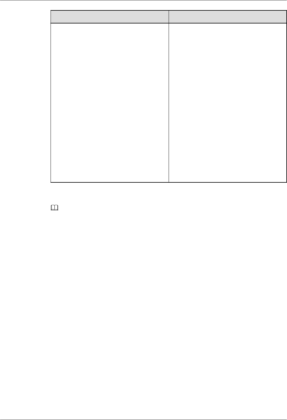
Figure 5-1 shows the components of DC 2-PIN round connector A.
AP4050DN-E
Hardware Installation and Maintenance Guide 5 Appendix
Issue 05 (2018-02-02) Huawei Proprietary and Confidential
Copyright © Huawei Technologies Co., Ltd.
36
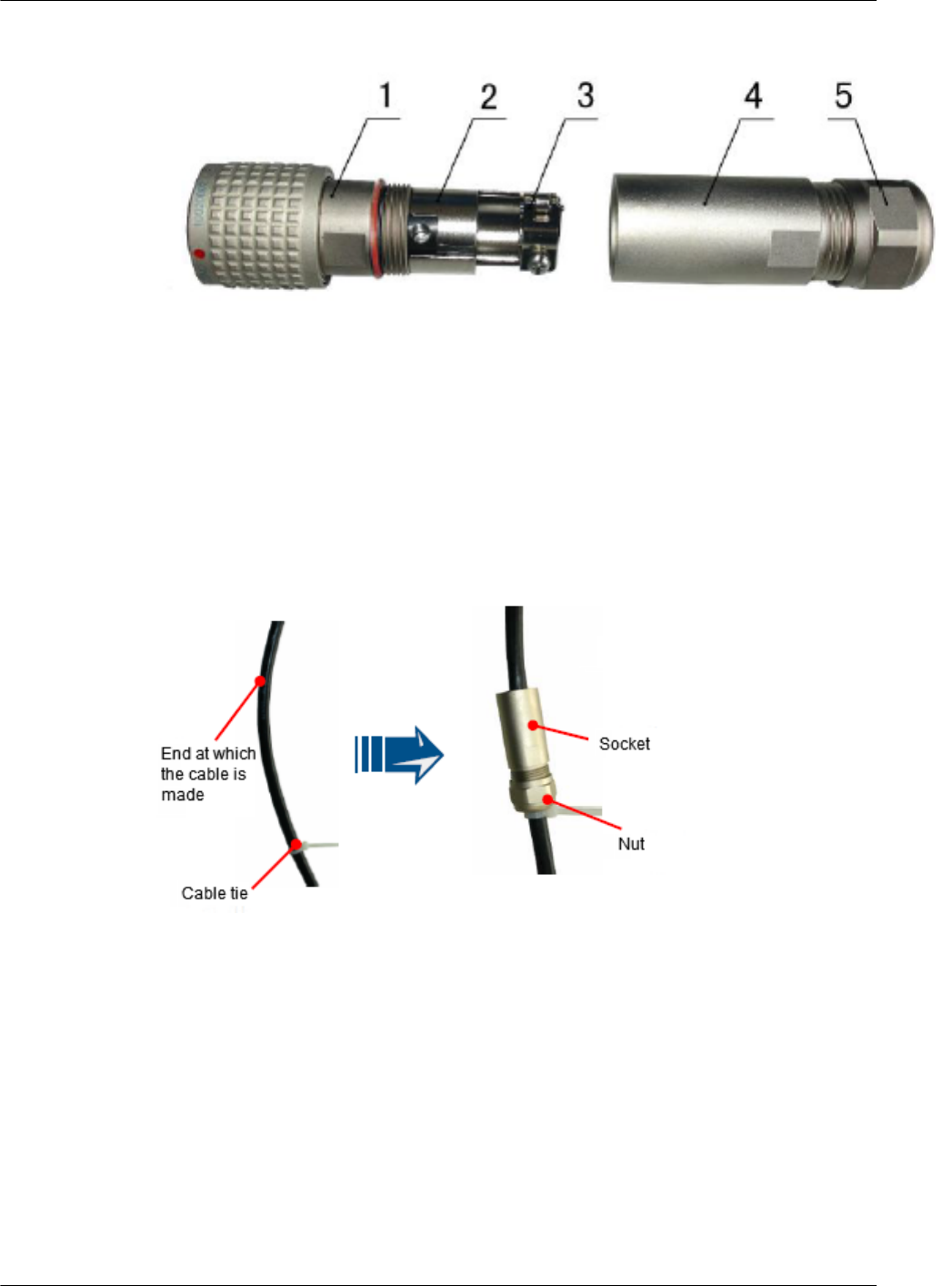
Figure 5-1 Components of DC 2-pin round connector A
1. Enclosure 2. Shield circle 3. Clip 4. Socket 5. Nut
Procedure
Step 1 Bind a cable tie, separate the socket and nut, and install them on the cable, as shown in Figure
5-2.
Figure 5-2 Installing the nut on the cable
Step 2 Strip the cable as shown in Figure 5-3.
AP4050DN-E
Hardware Installation and Maintenance Guide 5 Appendix
Issue 05 (2018-02-02) Huawei Proprietary and Confidential
Copyright © Huawei Technologies Co., Ltd.
37
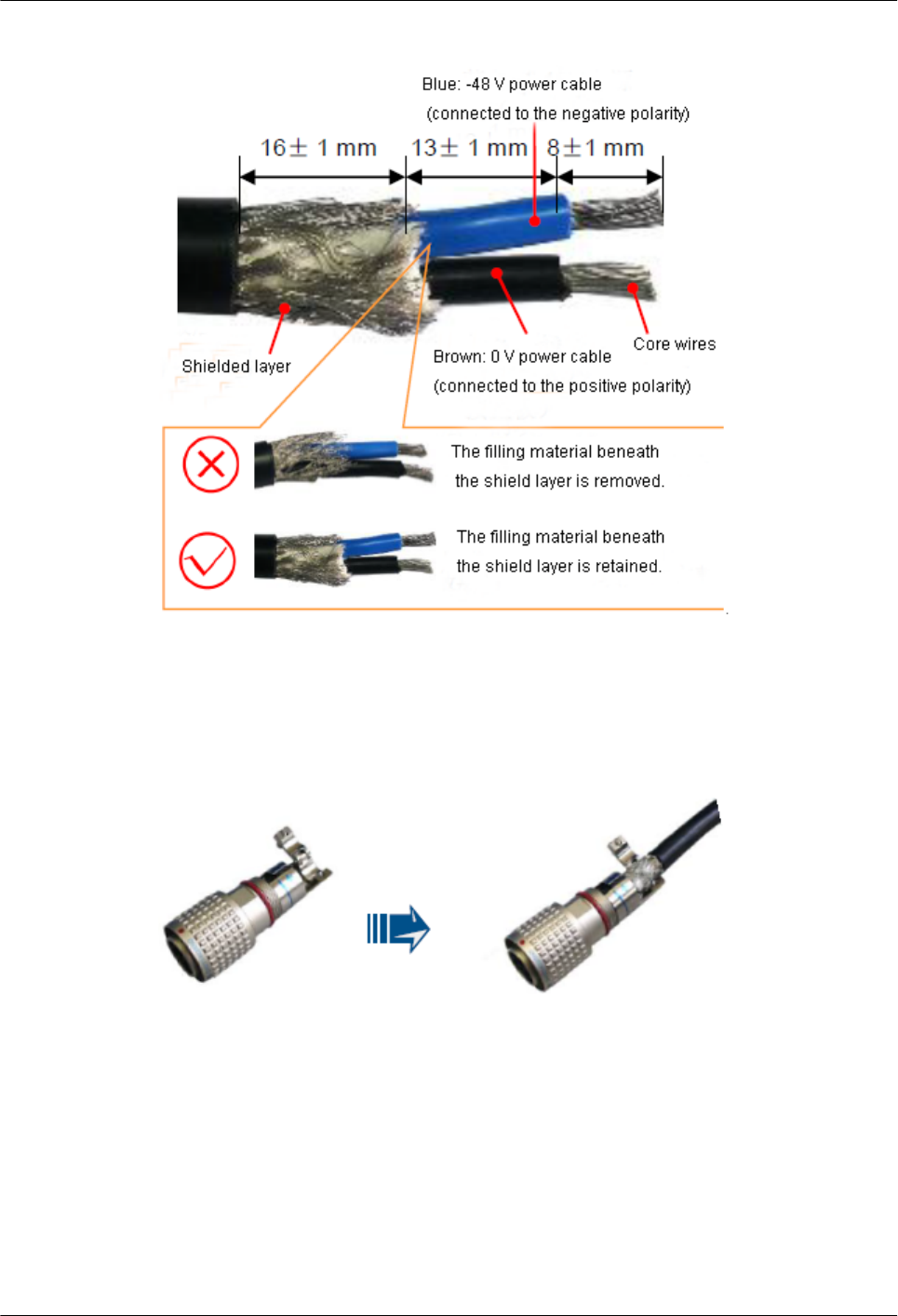
Figure 5-3 Stripping the cable
Step 3 Open the clip and correctly insert the core wires to the negative and positive holes, as shown
in Figure 5-4.
Figure 5-4 Inserting core wires
Step 4 Use a Phillips screwdriver to tighten the crimping screw in "+" hole, rotate the connector by
180 degree, and tighten the crimping screw in "-" hole, as shown in Figure 5-5.
AP4050DN-E
Hardware Installation and Maintenance Guide 5 Appendix
Issue 05 (2018-02-02) Huawei Proprietary and Confidential
Copyright © Huawei Technologies Co., Ltd.
38
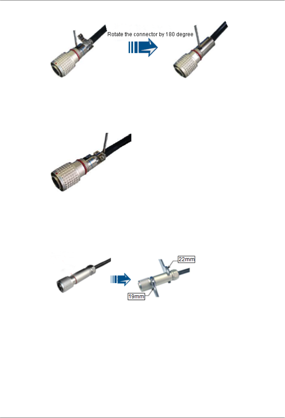
Figure 5-5 Tightening the crimping screws
Step 5 Close the clip and tighten the screw to compact the shield layer, as shown in Figure 5-6.
Figure 5-6 Compacting the shield layer
Step 6 Pre-tighten the socket and enclosure and use the Phillips screwdriver to tighten the socket
with the tightening torque no less than 1.2 N•m, as shown in Figure 5-7.
Figure 5-7 Tightening the socket
Step 7 Pre-tighten the socket and nut and use the Phillips screwdriver to tighten the nut with the
tightening torque no less than 1.2 N•m, as shown in Figure 5-8.
AP4050DN-E
Hardware Installation and Maintenance Guide 5 Appendix
Issue 05 (2018-02-02) Huawei Proprietary and Confidential
Copyright © Huawei Technologies Co., Ltd.
39
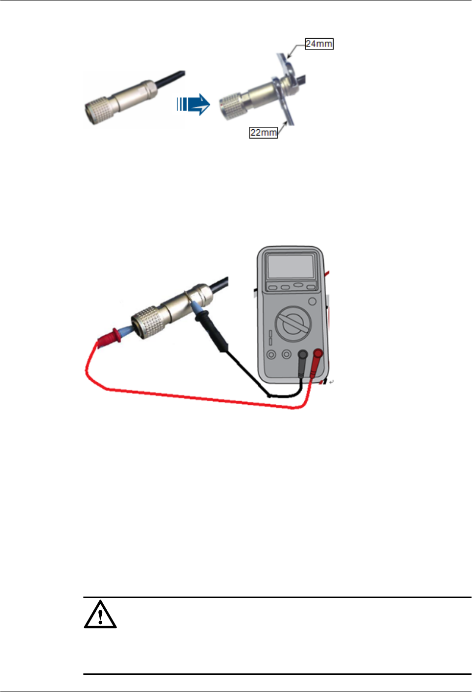
Figure 5-8 Tightening the nut
Step 8 Use a multimeter to check the connectivity of the 2-pin round connector's cable components,
as shown in Figure 5-9.
Figure 5-9 Checking connectivity
The connectivity meets standards if the following conditions are met:
lPositive and negative holes of the connector are not short-circuited.
lThe metal enclosure and connector's holes are not short-circuited.
lThe cable shield layer is properly connected to the metal enclosure.
lCore wires are properly connected to the connector's holes.
Step 9 If devices are installed outdoor, wrap three layers of PVC insulation tape around the
connector for protection, as shown in Figure 5-10.
NOTICE
Ensure that proper quantity of the PVC insulation tape is used for wrapping the connector,
facilitating the connector uninstallation in later maintenance.
AP4050DN-E
Hardware Installation and Maintenance Guide 5 Appendix
Issue 05 (2018-02-02) Huawei Proprietary and Confidential
Copyright © Huawei Technologies Co., Ltd.
40
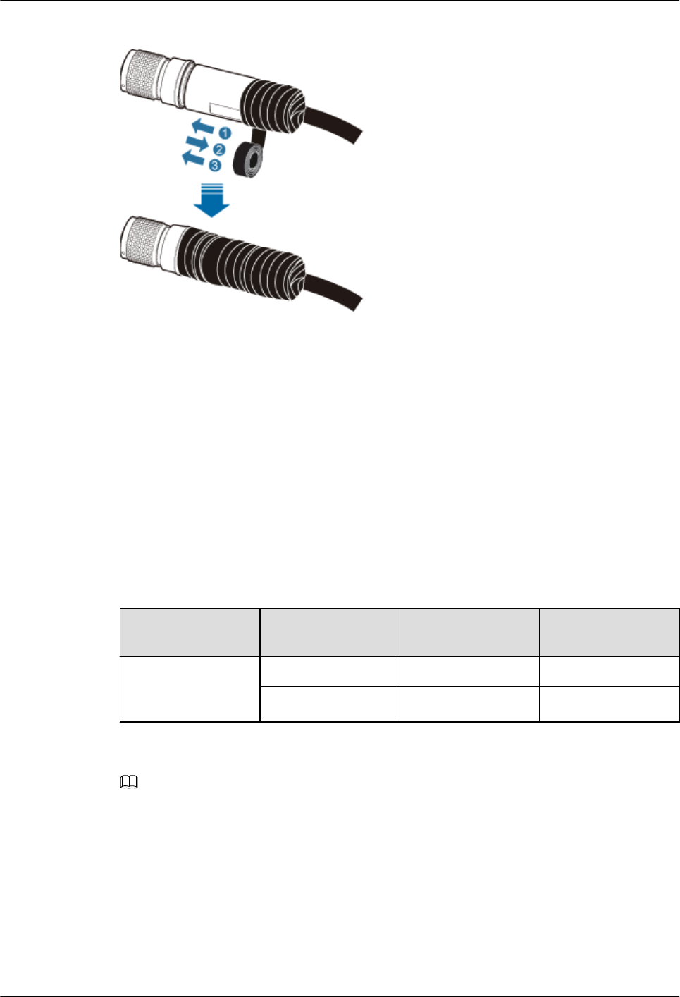
Figure 5-10 Wrapping PVC insulation tape
----End
5.1.2.2 Assembling a DC 2-Pin Round Connector (B)
This topic describes how to assemble a DC 2-pin round connector (B) and key operations.
Context
Table 5-1 lists power cables connected to the active antenna unit (AAU).
Table 5-1 AAU power cable
AAU Side Cable Commonly-Used
Colors
Colors Used in
Britain
DC round
waterproof
connector
RTN (+) Black or brown Blue
NEG (-) Blue Gray
NOTE
The color and appearance of cables in this topic are for reference only. The cable color and appearance
vary depending on countries and regions.
Figure 5-11 shows components of the DC round waterproof connector.
AP4050DN-E
Hardware Installation and Maintenance Guide 5 Appendix
Issue 05 (2018-02-02) Huawei Proprietary and Confidential
Copyright © Huawei Technologies Co., Ltd.
41
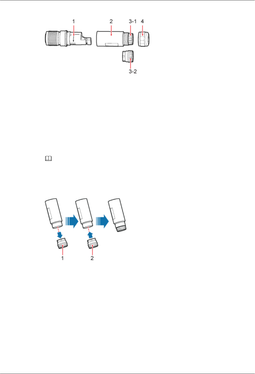
Figure 5-11 Components of the DC round waterproof connector
1. Enclosure 2. Socket 3-1. Clamping jaw 1 3-2. Clamping jaw 2 4. Nut
Procedure
Step 1 Determine the diameter of the cable to be installed. If the diameter is larger than 14 mm,
replace the clamping jaw, as shown in Figure 5-12. During the replacement, connect the
clamping jaw boss to the groove inside the socket and ensure that the clamping jaw is
completely installed in the socket, as shown in Figure 5-13.
NOTE
lPower cables supported by clamping jaw 1: 2 x 12 AWG, 2 x 4 mm2, and 2 x 6 mm2
lPower cables supported by clamping jaw 2: 2 x 8 AWG and 2 x 10 mm2
Figure 5-12 Replacing clamping jaws
1. Clamping jaw 1 2. Clamping jaw 2
AP4050DN-E
Hardware Installation and Maintenance Guide 5 Appendix
Issue 05 (2018-02-02) Huawei Proprietary and Confidential
Copyright © Huawei Technologies Co., Ltd.
42
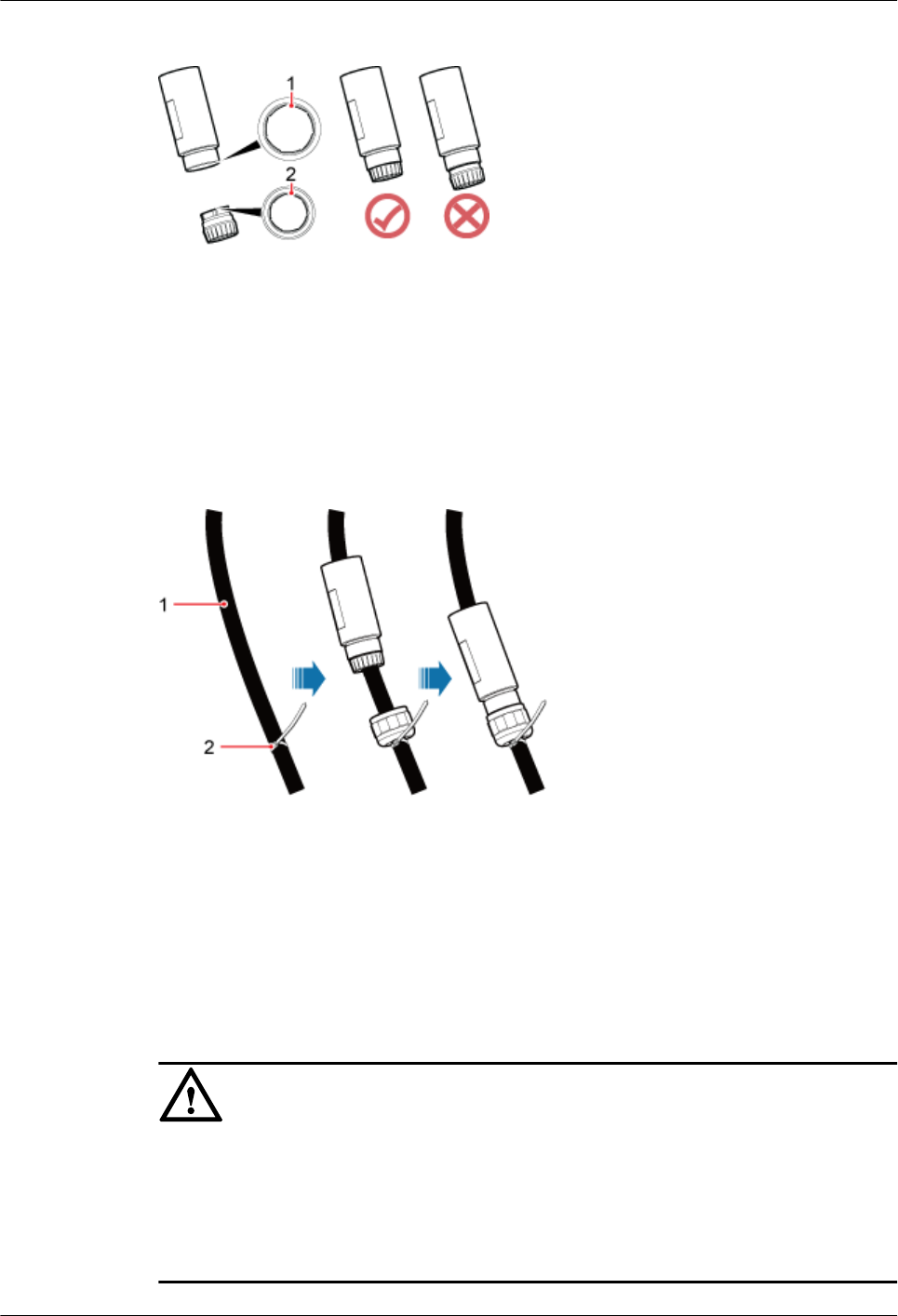
Figure 5-13 Correct operation for replacing a clamping jaw
1. Groove 2. Boss
Step 2 Reserve the cable length at the assembly end, bind the plastic cable tie, install the nut,
clamping jaw, and socket on the cable and pre-tighten them, as shown in Figure 5-14.
Figure 5-14 Pre-tightening
1. Cable 2. Plastic cable tie
Step 3 Use the stripping ruler card to measure required lengths, strip the outer jacket (48 mm) on the
head of the cable to be connected and the outer jacket (17 mm) of each core wire, twist the
shield layers into one strand, as shown in Figure 5-15.
NOTICE
lThe stripping ruler card is delivered with the components of the connector.
lCut the padding using diagonal pliers.
lGently strip the insulation sheath to avoid damage to the conductor metal.
lEnsure that the edge of core wires is not split.
AP4050DN-E
Hardware Installation and Maintenance Guide 5 Appendix
Issue 05 (2018-02-02) Huawei Proprietary and Confidential
Copyright © Huawei Technologies Co., Ltd.
43
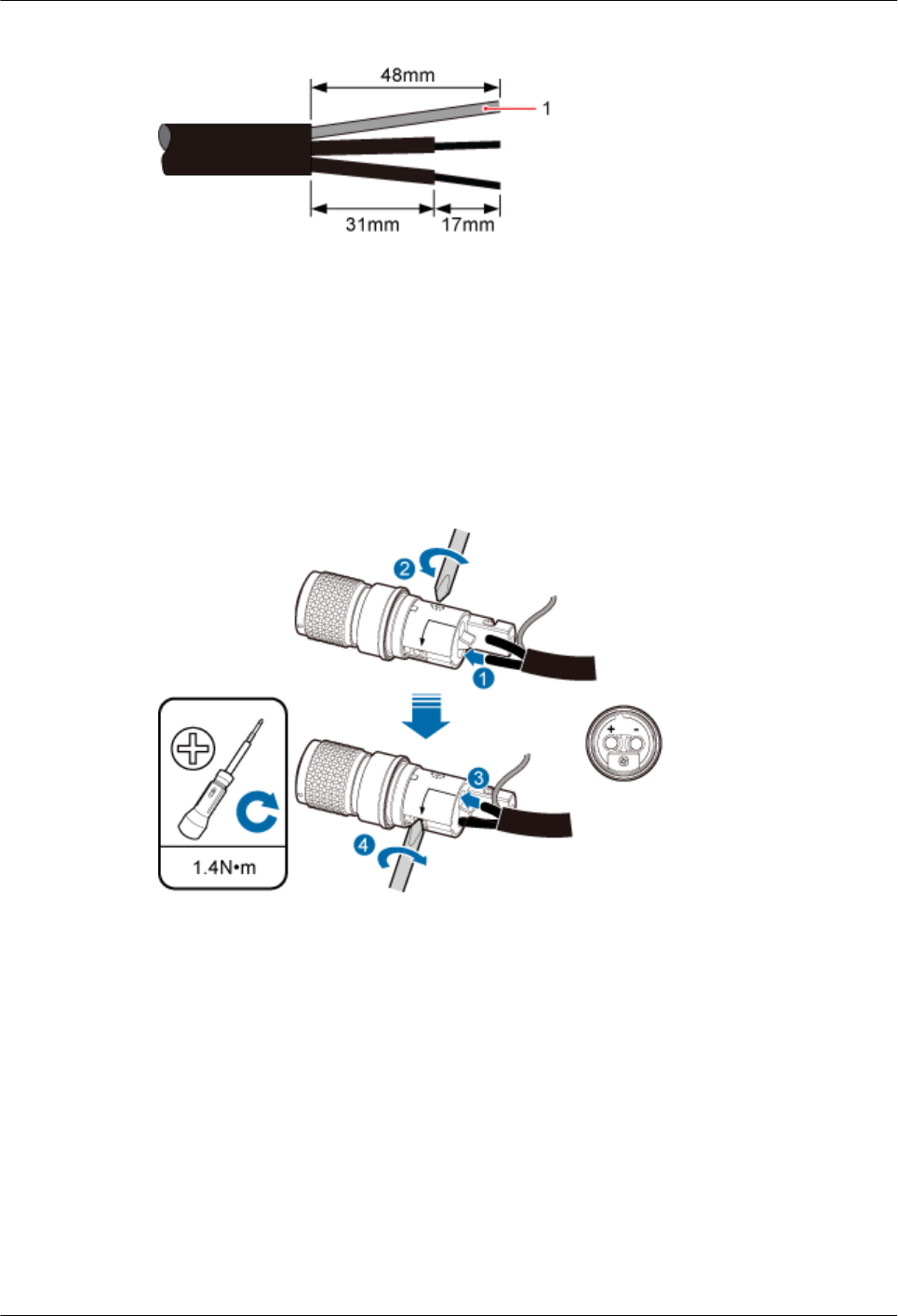
Figure 5-15 Stripping the cable
1. Shield layer
Step 4 Connect the cable NEG (-) (gray in Britain and blue in other countries) to - end of the
connector and cable RTN (+) (blue in Britain and black/brown in other countries) to + end of
the connector. Tighten two crimping screws using the Phillips screwdriver and compact the
cable with tightening torque 1.4 N•m, as shown in Figure 5-16.
Figure 5-16 Tightening the crimping screws
Step 5 After the cables are assembled, pull the cables slightly to check whether the connections are
secure. If the cable slides outward or the wire of the cable is exposed outside the hole for the
cable, remove the cable, cut the split wires, and then strip the jacket and install the cable
again.
Step 6 Twist the shield layers into one strand and insert it into the shield slot, tighten the tail screw,
and fasten the shielded layer with tightening torque 1.4 N•m, as shown in Figure 5-17.
AP4050DN-E
Hardware Installation and Maintenance Guide 5 Appendix
Issue 05 (2018-02-02) Huawei Proprietary and Confidential
Copyright © Huawei Technologies Co., Ltd.
44
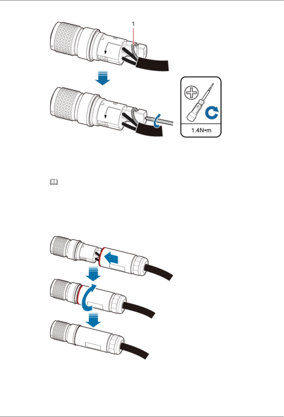
Figure 5-17 Compacting the shield layer
1. Shield layer
NOTE
Cut the extra shield layer using the diagonal pliers.
Step 7 Tighten the socket and enclosure until the red line on the socket is invisible, as shown in
Figure 5-18.
Figure 5-18 Tightening the socket and enclosure
Step 8 Pre-tighten the nut and socket and further tighten the nut using a torque wrench (opening
width: 28 mm), as shown in Figure 5-19.
AP4050DN-E
Hardware Installation and Maintenance Guide 5 Appendix
Issue 05 (2018-02-02) Huawei Proprietary and Confidential
Copyright © Huawei Technologies Co., Ltd.
45
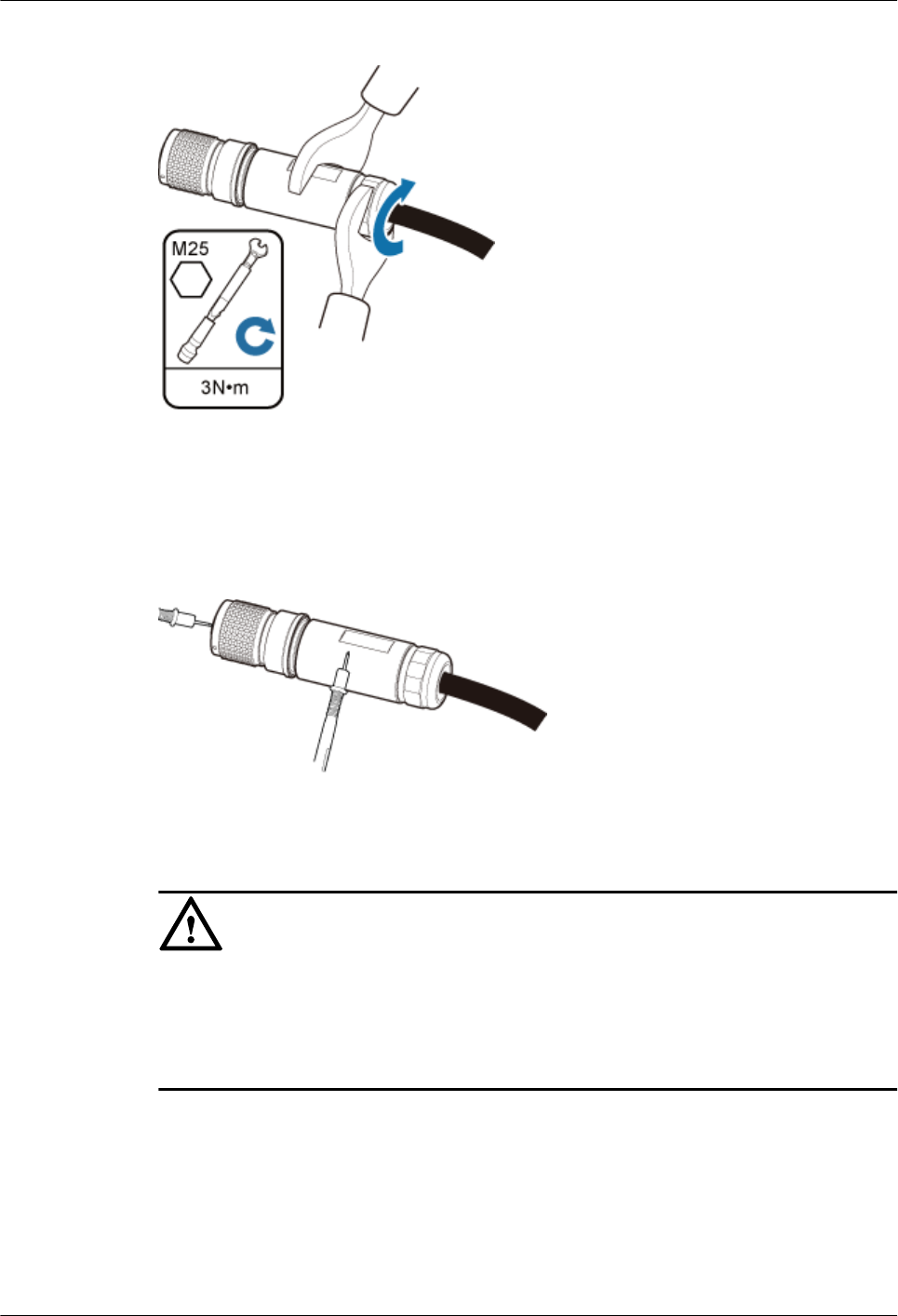
Figure 5-19 Tightening the nut
Step 9 Use a multimeter to check the reliability of cable components, as shown in Figure 5-20.
Figure 5-20 Checking reliability
NOTICE
lEnsure that the short circuit does not occur between the positive and negative holes of
the connector.
lEnsure that the short circuit does not occur between the metal enclosure and connector's
positive and negative holes.
Step 10 If devices are installed outdoor, wrap three layers of PVC insulation tape around the
connector for protection, as shown in Figure 5-21.
AP4050DN-E
Hardware Installation and Maintenance Guide 5 Appendix
Issue 05 (2018-02-02) Huawei Proprietary and Confidential
Copyright © Huawei Technologies Co., Ltd.
46
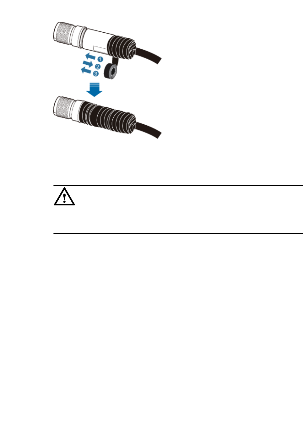
Figure 5-21 Wrapping PVC insulation tape
NOTICE
Ensure that proper quantity of the PVC insulation tape is used for wrapping the connector,
facilitating the connector uninstallation in later maintenance.
----End
5.1.2.3 Assembling the OT Terminal and Power Cable
Context
Figure 5-22 shows the components of an OT terminal and a power cable.
AP4050DN-E
Hardware Installation and Maintenance Guide 5 Appendix
Issue 05 (2018-02-02) Huawei Proprietary and Confidential
Copyright © Huawei Technologies Co., Ltd.
47
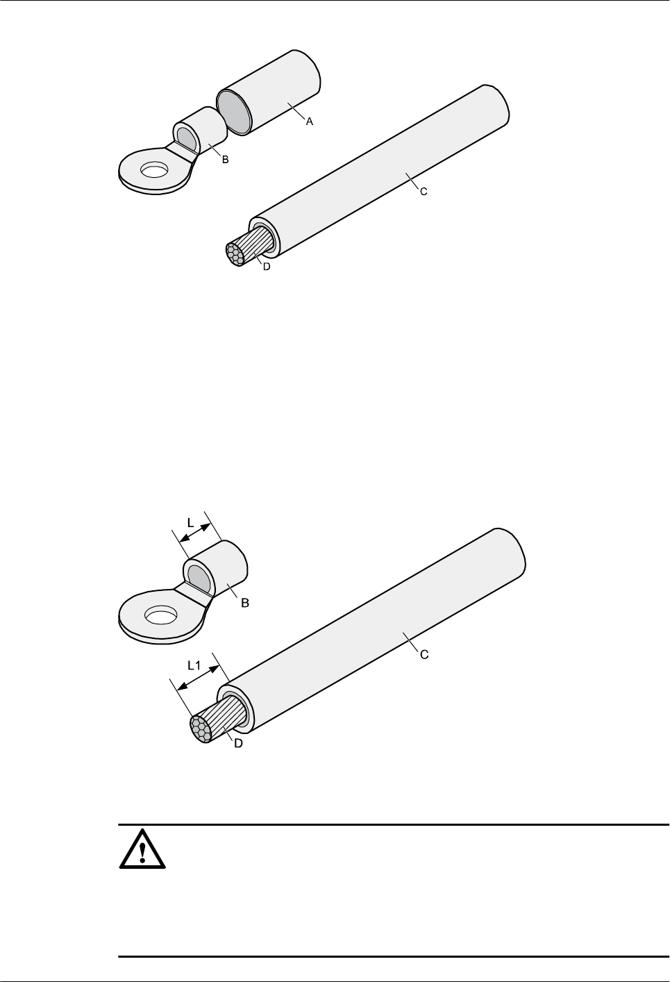
Figure 5-22 Components of an OT terminal and a power cable
A. Heat-shrinkable tubing B. Bare crimping terminal C. Insulation D. Conductor
Procedure
Step 1 Based on the cross-sectional area of the cable conductor, strip a length of insulation coating C
to expose the conductor D of length L1, as shown in Figure 5-23. The recommended values
of L1 are listed in Table 5-2.
Figure 5-23 Stripping a power cable (OT terminal)
NOTICE
lWhen you strip a power cable, do not damage the conductor of the cable.
lIf the bare crimping terminal is not provided by Huawei, the value of L1 is 1 mm (0.04 in.)
to 2 mm (0.08 in.) greater than the value of L.
AP4050DN-E
Hardware Installation and Maintenance Guide 5 Appendix
Issue 05 (2018-02-02) Huawei Proprietary and Confidential
Copyright © Huawei Technologies Co., Ltd.
48
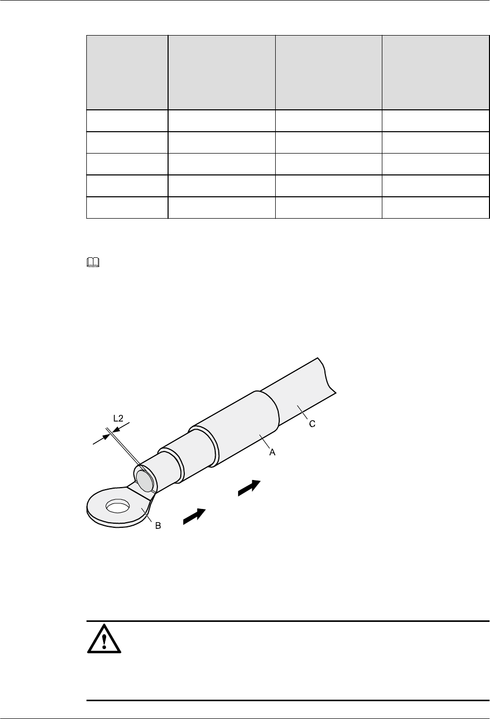
Table 5-2 Mapping between the cross-sectional area of the conductor and the value of L1
Cross-
Sectional
Area of
Conductor
(mm2(in.2))
Value of L1
(mm(in.))
Cross-Sectional
Area of Conductor
(mm2(in.2))
Value of L1
(mm(in.))
1 (0.002) 7 (0.28) 10 (0.015) 11 (0.43)
1.5 (0.002) 7 (0.28) 16 (0.025) 13 (0.51)
2.5 (0.004) 7 (0.28) 25 (0.039) 14 (0.55)
4 (0.006) 8 (0.31) 35 (0.054) 16 (0.63)
6 (0.009) 9 (0.35) 50 (0.077) 16 (0.63)
NOTE
If you are proficient in assembling OT terminals and power cables, you can obtain the value of L1 by
comparing the part to be crimped with the power cable.
Step 2 Put the heat-shrinkable (A) tubing onto the bare crimping terminal, as shown in Figure 5-24.
Figure 5-24 Putting the heat shrink tubing onto the bare crimping terminal
Step 3 Put the OT terminal B onto the exposed conductor, and ensure that the OT terminal is in good
contact with the insulation coating C, as shown in Figure 5-24.
NOTICE
After the conductor is fed into the OT terminal, the protruding part of the conductor, or L2 in
Figure 5-24, must not be longer than 2 mm (0.08 in.).
AP4050DN-E
Hardware Installation and Maintenance Guide 5 Appendix
Issue 05 (2018-02-02) Huawei Proprietary and Confidential
Copyright © Huawei Technologies Co., Ltd.
49
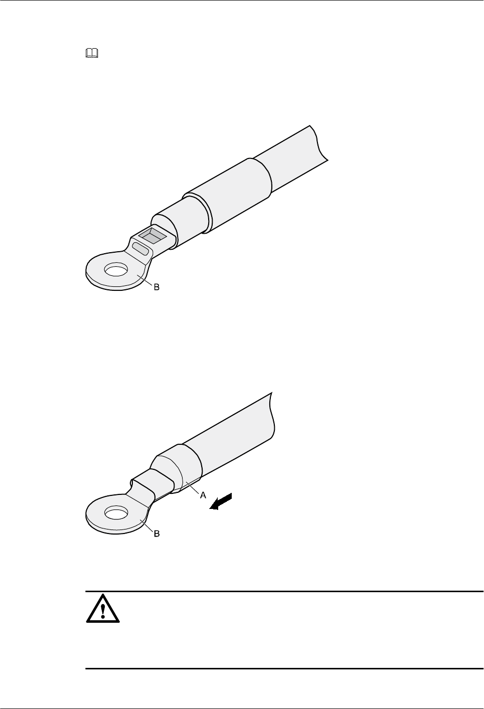
Step 4 Crimp the joint parts of the bare crimping terminal and the conductor, as shown in Figure
5-25.
NOTE
The shapes of crimped parts may vary with the crimping dies.
Figure 5-25 Crimping the joint parts of the bare crimping terminal and the conductor (OT
terminal)
Step 5 Push the heat shrink tubing (A) toward the connector until the tube covers the crimped part,
and then use a heat gun to heat the tube, as shown in Figure 5-26.
Figure 5-26 Heating the heat shrink tubing (OT terminal)
NOTICE
Stop heating the shrink tubing when the connector is securely locked in the shrink tubing. Do
not heat the shrink tubing too long as this may damage the insulation coating.
----End
AP4050DN-E
Hardware Installation and Maintenance Guide 5 Appendix
Issue 05 (2018-02-02) Huawei Proprietary and Confidential
Copyright © Huawei Technologies Co., Ltd.
50
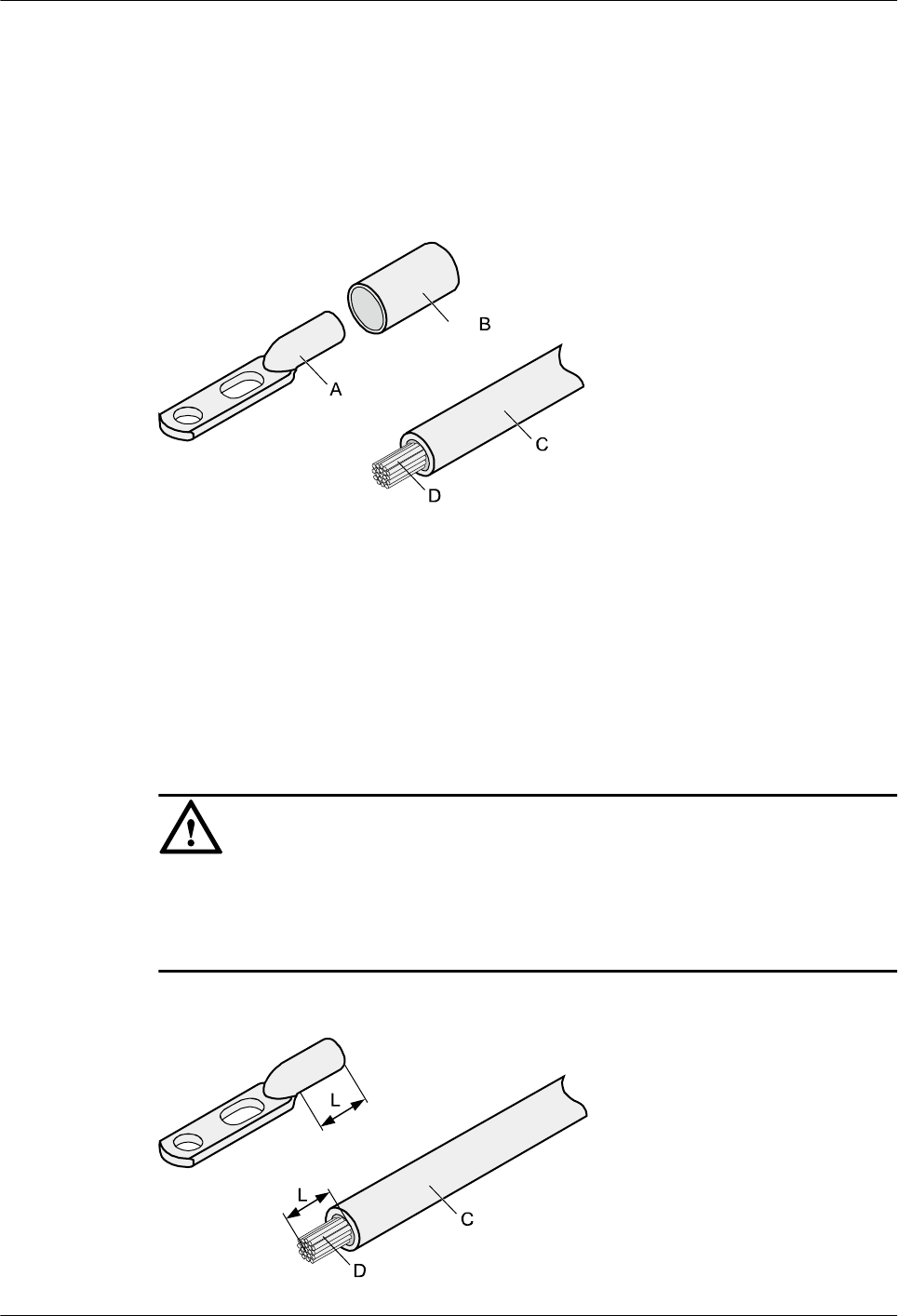
5.1.2.4 Assembling the JG Terminal and Power Cable
Context
Figure 5-27 shows the components of a JG terminal and a power cable.
Figure 5-27 Components of a JG terminal and a power cable
A. JG terminal B. Heat-shrinkable tubing C. Insulation layer of a power
cable
D. Conductor of a power cable
Procedure
Step 1 Strip a part of the insulation to expose the cable conductor with a length of L, as shown in
Figure 5-28. The recommended values of L are listed in Table 5-3.
NOTICE
lWhen you strip a power cable, do not damage the conductor of the cable.
lIf the bare crimping terminal is not provided by Huawei, you can adjust the value of L as
required.
Figure 5-28 Stripping a power cable (JG terminal)
AP4050DN-E
Hardware Installation and Maintenance Guide 5 Appendix
Issue 05 (2018-02-02) Huawei Proprietary and Confidential
Copyright © Huawei Technologies Co., Ltd.
51
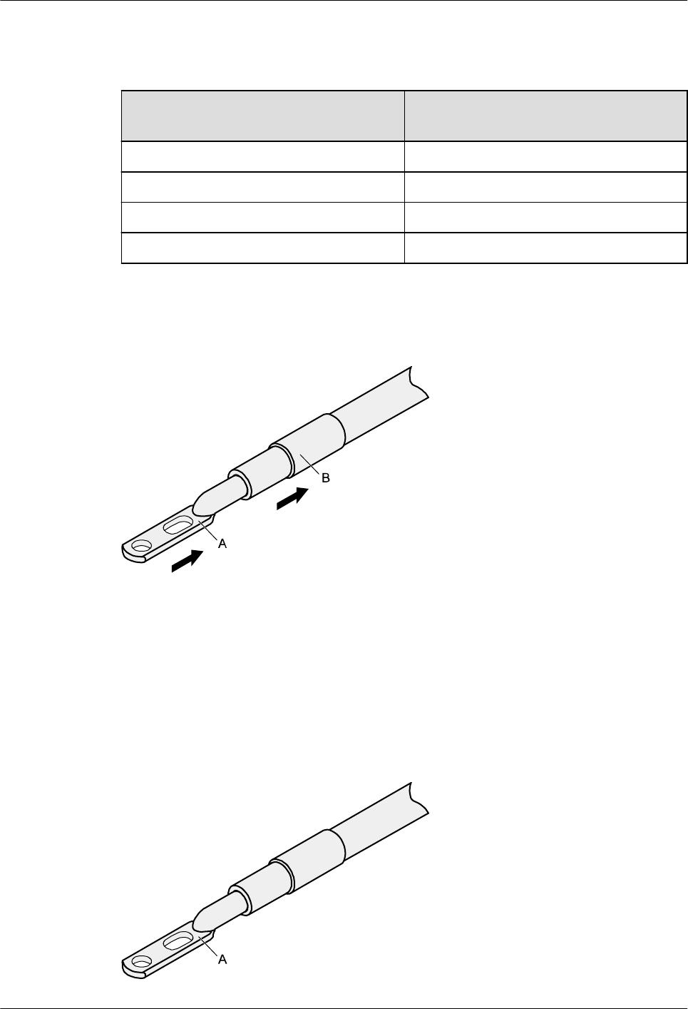
Table 5-3 Mapping between the cross-sectional area of the conductor and the value of L
Cross-Sectional Area of Conductor
(mm2(in.2))
Value of L (mm(in.))
16 (0.025) 13 (0.51)
25 (0.039) 14 (0.55)
35 (0.054) 16 (0.63)
50 (0.077) 16 (0.63)
Step 2 Put the heat shrink tubing onto the bare crimping terminal, as shown in Figure 5-29.
Figure 5-29 Putting the heat shrink tubing onto the bare crimping terminal
Step 3 Put the bare crimping terminal onto the exposed conductor, and ensure that the bare crimping
terminal is in good contact with the insulation of the power cable, as shown in Figure 5-29.
Step 4 Crimp the joint parts of the bare crimping terminal and the conductor, as shown in Figure
5-30.
Figure 5-30 Crimping the joint parts of the bare crimping terminal and the conductor (JG
terminal)
AP4050DN-E
Hardware Installation and Maintenance Guide 5 Appendix
Issue 05 (2018-02-02) Huawei Proprietary and Confidential
Copyright © Huawei Technologies Co., Ltd.
52
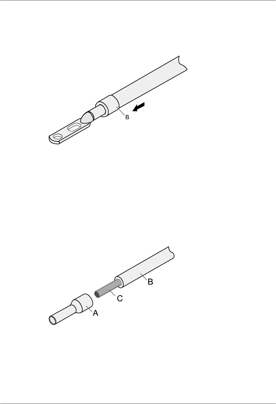
Step 5 Push the heat shrink tubing toward the connector until the tube covers the crimped part, and
then use a heat gun to heat the tube, as shown in Figure 5-31.
Figure 5-31 Heating the heat shrink tubing (JG terminal)
----End
5.1.2.5 Assembling the Cord End Terminal and the Power Cable
Context
Figure 5-32 shows the components of a cord end terminal and a power cable.
Figure 5-32 Components of a cord end terminal and a power cable
A. Cord end terminal B. Insulation layer of a power cable C. Conductor of a power cable
Procedure
Step 1 Strip a part of the insulation to expose the cable conductor with a length of L1, as shown in
Figure 5-33. The recommended values of L1 are listed in Table 5-4.
AP4050DN-E
Hardware Installation and Maintenance Guide 5 Appendix
Issue 05 (2018-02-02) Huawei Proprietary and Confidential
Copyright © Huawei Technologies Co., Ltd.
53
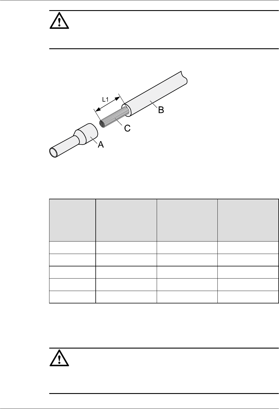
NOTICE
When you strip a power cable, do not damage the conductor of the cable.
Figure 5-33 Stripping a power cable (cord end terminal)
Table 5-4 Mapping between the cross-sectional area of the conductor and the value of L1
Cross-
Sectional
Area of
Conductor
(mm2(in.2))
Value of L1
(mm(in.))
Cross-Sectional
Area of Conductor
(mm2(in.2))
Value of L1
(mm(in.))
1 (0.002) 8 (0.31) 10 (0.015) 15 (0.59)
1.5 (0.002) 10 (0.39) 16 (0.025) 15 (0.59)
2.5 (0.004) 10 (0.39) 25 (0.039) 18 (0.71)
4 (0.006) 12 (0.47) 35 (0.054) 19 (0.75)
6 (0.009) 14 (0.55) 50 (0.077) 26 (1.02)
Step 2 Put the cord end terminal onto the conductor, and ensure that the conductor is aligned with the
edge of the cord end terminal, as shown in Figure 5-34.
NOTICE
After the conductor is fed into the cord end terminal, the protruding part of the conductor
must not be longer than 1 mm (0.04 in.).
AP4050DN-E
Hardware Installation and Maintenance Guide 5 Appendix
Issue 05 (2018-02-02) Huawei Proprietary and Confidential
Copyright © Huawei Technologies Co., Ltd.
54
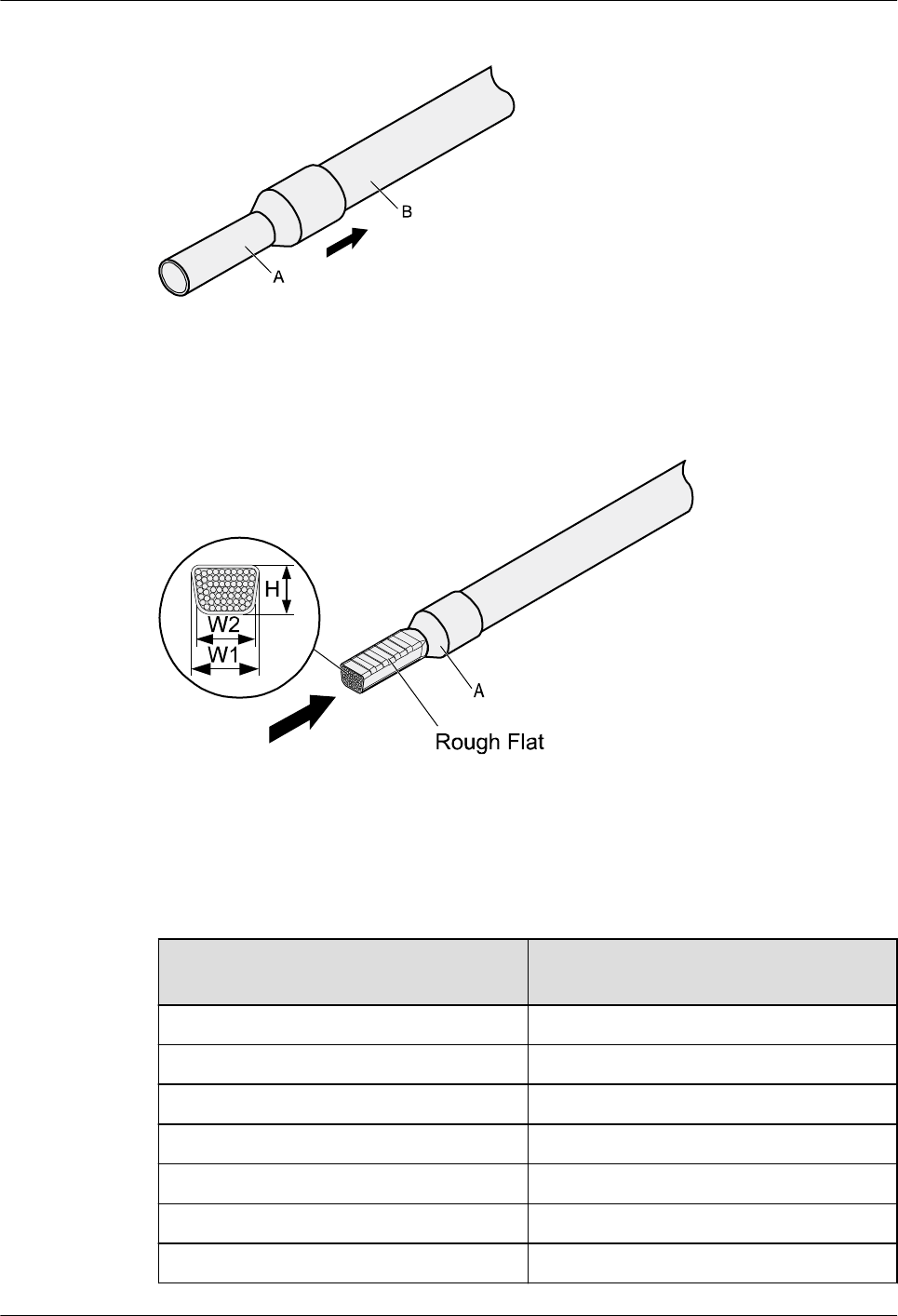
Figure 5-34 Putting the cord end terminal onto the conductor
Step 3 Crimp the joint parts of the cord end terminal and the conductor, as shown in Figure 5-35.
Figure 5-35 Crimping the cord end terminal and the conductor
Step 4 Check the maximum width of the tubular crimped terminal. The maximum width of a tubular
crimped terminal is listed in Table 5-5.
Table 5-5 Maximum width of a tubular crimped terminal
Cross-Sectional Area of Tubular
Terminal (mm2(in.2))
Maximum Width of Crimped Terminal
W1 (mm(in.))
0.25 (0.0004) 1 (0.04)
0.5 (0.0008) 1 (0.04)
1.0 (0.0015) 1.5 (0.06)
1.5 (0.0023) 1.5 (0.06)
2.5 (0.0039) 2.4 (0.09)
4 (0.006) 3.1 (0.12)
6 (0.009) 4 (0.16)
AP4050DN-E
Hardware Installation and Maintenance Guide 5 Appendix
Issue 05 (2018-02-02) Huawei Proprietary and Confidential
Copyright © Huawei Technologies Co., Ltd.
55
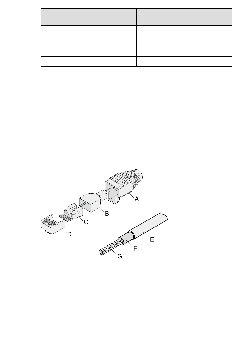
Cross-Sectional Area of Tubular
Terminal (mm2(in.2))
Maximum Width of Crimped Terminal
W1 (mm(in.))
10 (0.015) 5.3 (0.21)
16 (0.025) 6 (0.24)
25 (0.039) 8.7 (0.34)
35 (0.054) 10 (0.39)
----End
5.1.3 Assembling Ethernet Cables
5.1.3.1 Assembling the Shielded RJ45 Connector and Ethernet Cable
Context
Figure 5-36 shows the components of an RJ45 connector and a shielded Ethernet cable.
Figure 5-36 Shielded RJ45 connector and cable
A. Jacket of connector B. Metal shell of connector C. Wire holder of
connector
D. Plug of connector
E. Jacket of Ethernet cable F. Shield layer of Ethernet
cable
G. Twisted-pair wires -
Procedure
Step 1 Fit the jacket of the connector onto the Ethernet cable, as shown in Figure 5-37.
AP4050DN-E
Hardware Installation and Maintenance Guide 5 Appendix
Issue 05 (2018-02-02) Huawei Proprietary and Confidential
Copyright © Huawei Technologies Co., Ltd.
56
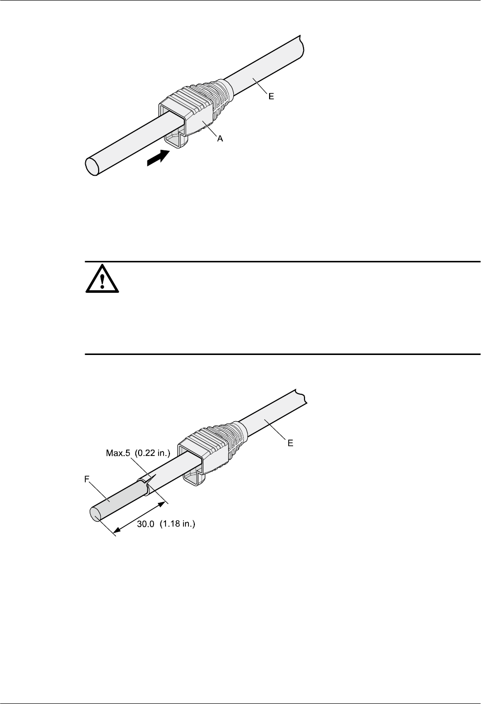
Figure 5-37 Fitting the jacket of the connector onto the Ethernet cable
Step 2 Remove a 30 mm (1.18 in.) long section of the jacket, cut off the nylon twine inside the
jacket, and cut a no more than 5 mm (0.20 in.) cleft in the jacket, as shown in Figure 5-38.
NOTICE
lWhen you remove a section of the jacket, do not damage the shield layer of the twisted-
pair cable.
lWhen you remove the shield layer, do not damage the insulation of the twisted-pair cable.
Figure 5-38 Removing the jacket of a twisted-pair cable (unit: mm (in.))
Step 3 Fit the metal shell onto the twisted-pair cable. The shield layer is covered by the metal shell,
as shown in Figure 5-39.
AP4050DN-E
Hardware Installation and Maintenance Guide 5 Appendix
Issue 05 (2018-02-02) Huawei Proprietary and Confidential
Copyright © Huawei Technologies Co., Ltd.
57
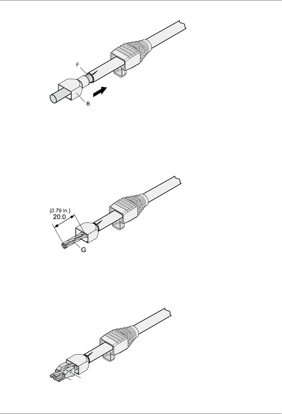
Figure 5-39 Fitting the metal shell onto the twisted-pair cable
Step 4 Fit the metal shell onto the twisted-pair cable until the shield layer is covered completely.
Along the edge of the metal shell, cut off the aluminum foil shield layer and ensure that there
is no surplus copper wire. The exposed twisted-pair cable is about 20 mm (0.79 in.) long, as
shown in Figure 5-40.
Figure 5-40 Removing the shield layer of a twisted-pair cable (unit: mm (in.))
Step 5 Lead the four pairs of twisted-pair wires through the wire holder, as shown in Figure 5-41 and
Figure 5-42. Ensure that the colored wires are in the correct location in the cable.
Figure 5-41 Leading wires through the wire holder
C
G
AP4050DN-E
Hardware Installation and Maintenance Guide 5 Appendix
Issue 05 (2018-02-02) Huawei Proprietary and Confidential
Copyright © Huawei Technologies Co., Ltd.
58
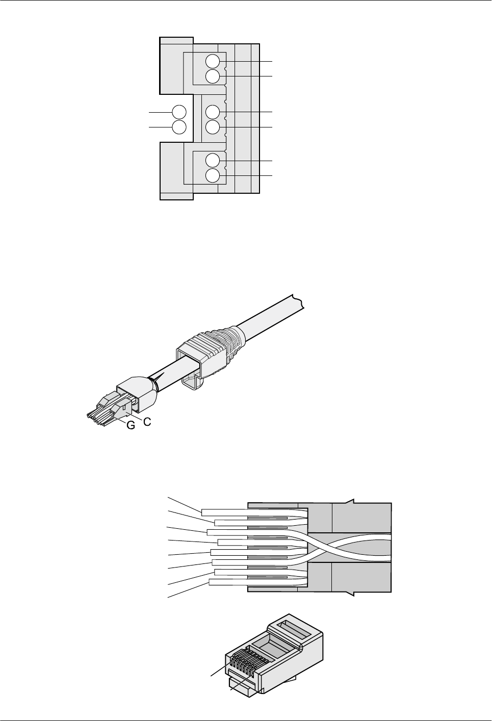
Figure 5-42 Cable locations in a wire holder
White-Green
Green
White-Orange
Orange
Blue
White-Blue
White-Brown
Brown
Step 6 Align the four pairs of cables in the holder, as shown in Figure 5-43. The connections
between the wires and the pins are shown in Figure 5-44 and listed in Table 5-6.
Figure 5-43 Four pairs of cables on a wire holder
Figure 5-44 Connections between wires and pins
Brown
White -Brown
Green
White-Blue
Blue
White-Green
Orange
White-Orange
Pin 8
Pin 1
AP4050DN-E
Hardware Installation and Maintenance Guide 5 Appendix
Issue 05 (2018-02-02) Huawei Proprietary and Confidential
Copyright © Huawei Technologies Co., Ltd.
59
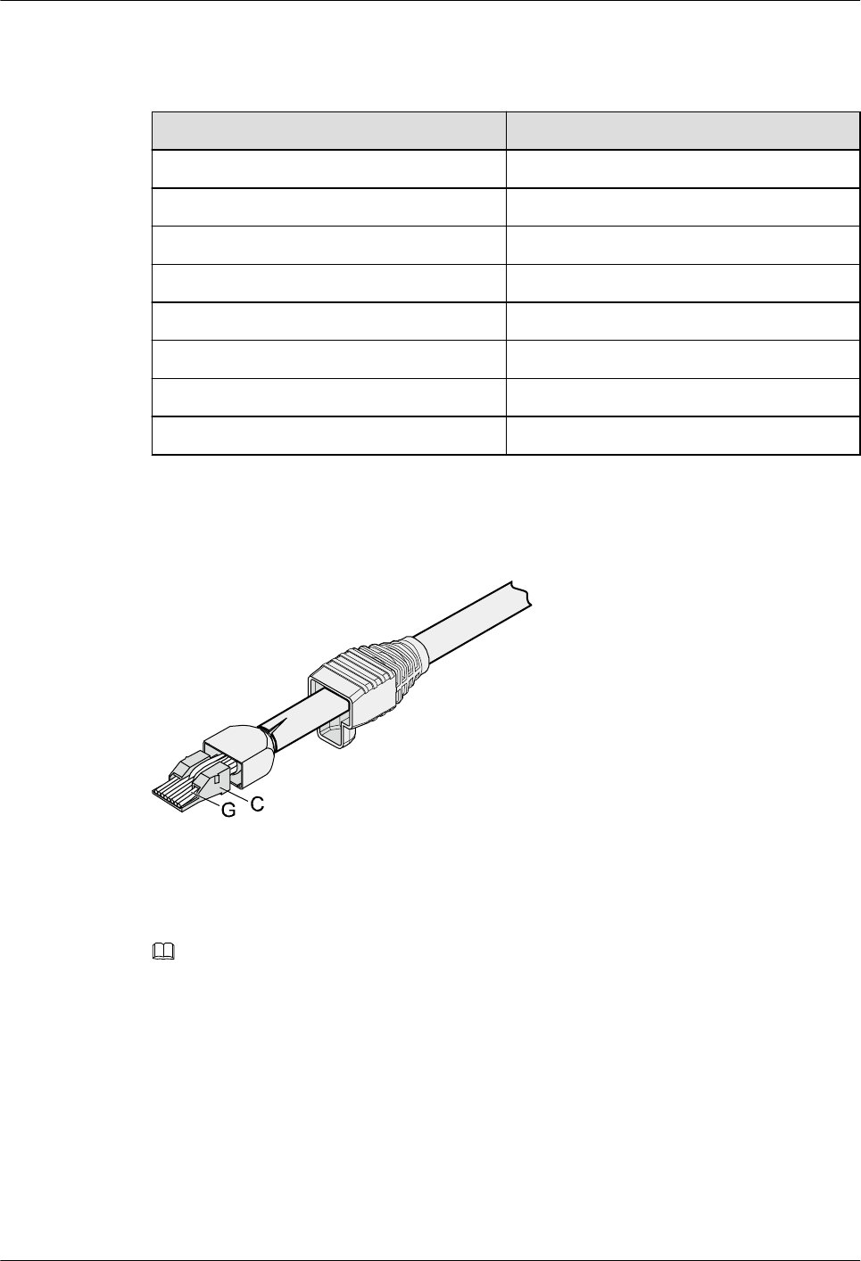
Table 5-6 Connections between wires and pins (using a straight-through cable as an example)
Matching Pins of Wires Wire Color
1 White-Orange
2 Orange
3 White-Green
4 Blue
5 White-Blue
6 Green
7 White-Brown
8 Brown
Step 7 Cut off the surplus cables along the lower edge of the wire holder, as shown in Figure 5-45.
Figure 5-45 Cutting off surplus cables
Step 8 Put the connector body onto the wire holder and turn the metal shell by 90°, as shown in
Figure 5-46.
NOTE
Ensure that the wire holder is in good contact with the connector body.
AP4050DN-E
Hardware Installation and Maintenance Guide 5 Appendix
Issue 05 (2018-02-02) Huawei Proprietary and Confidential
Copyright © Huawei Technologies Co., Ltd.
60
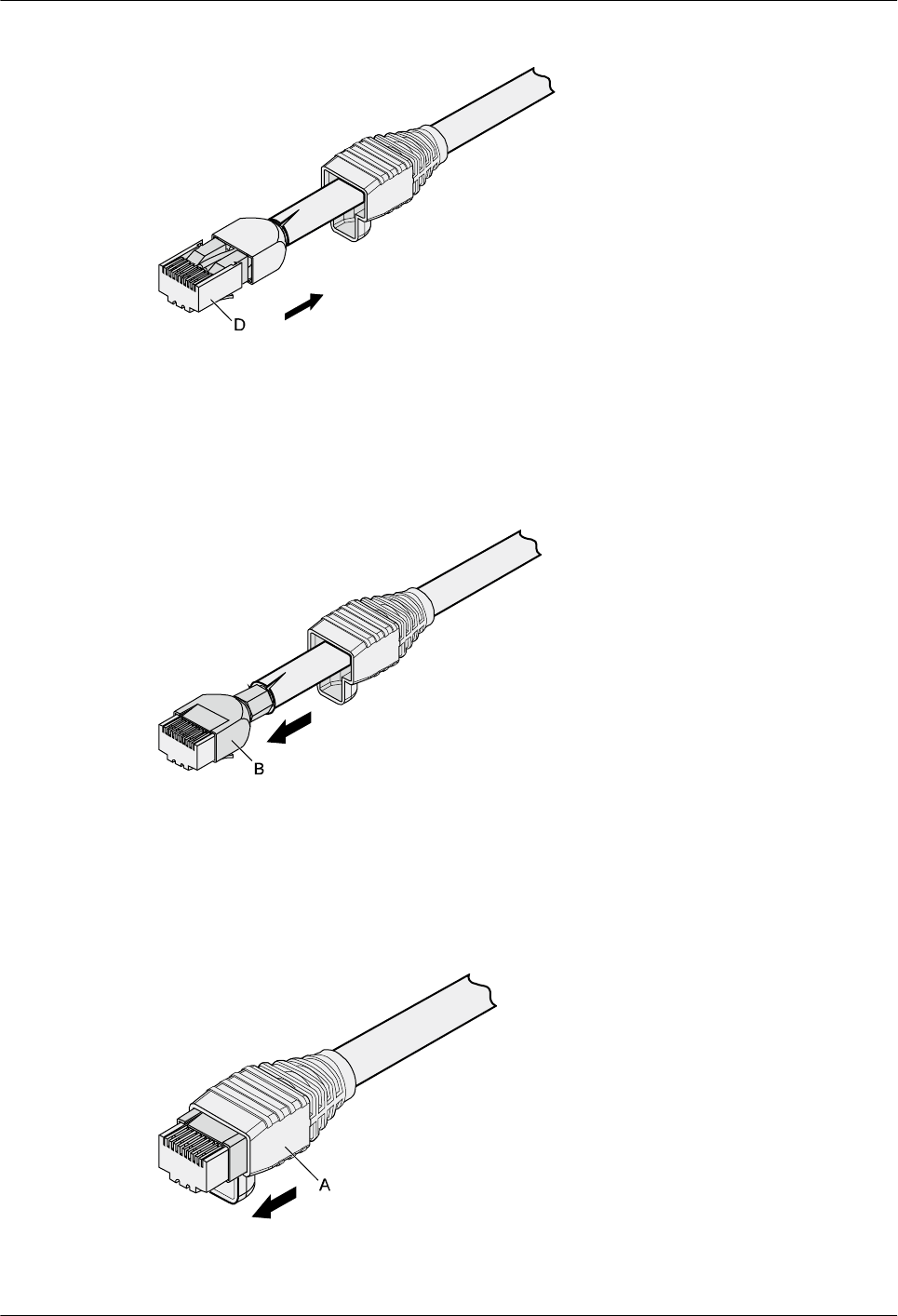
Figure 5-46 Putting the connector body onto the wire holder
Step 9 Push the metal shell toward the connector body until the wire holder and the connector body
are engaged completely. Crimp the connector, as shown in Figure 5-47.
Figure 5-47 Crimping the connector
Step 10 Push the jacket towards the metal shell until the metal shell is covered. This completes the
assembly of one end of the cable, as shown in Figure 5-48.
Figure 5-48 Pushing the metal shell
AP4050DN-E
Hardware Installation and Maintenance Guide 5 Appendix
Issue 05 (2018-02-02) Huawei Proprietary and Confidential
Copyright © Huawei Technologies Co., Ltd.
61
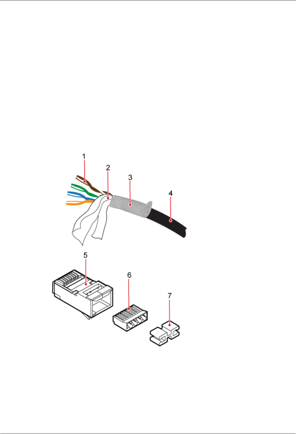
Step 11 To complete the assembly of the other end, repeat steps 1 to 10.
----End
5.1.3.2 Assembling an Optimized Shielded RJ45 Connector and SFTP Network
Cables
Context
This topic describes how to assemble an optimized shielded RJ45 connector with a Secure
File Transfer Protocol (SFTP) straight-through network cable as an example. The connector
has a cable support rack but does not have a metal jacket. Such a connector can be used for
crimping CAT. 6 network cables.
Figure 5-49 shows the shielded RJ45 connector.
Figure 5-49 Shielded RJ45 connector
1: Core
wires
2: Aluminum foil 3: Braid
shield
4: Outer
jacket
5: RJ45
connector
6: Load bar 7: Cable support
rack
Procedure
Step 1 Strip 20 mm outer jacket off the network cable, peel off the braid shield backward, and cut off
the aluminum foil and protection band, as shown in Figure 5-50.
AP4050DN-E
Hardware Installation and Maintenance Guide 5 Appendix
Issue 05 (2018-02-02) Huawei Proprietary and Confidential
Copyright © Huawei Technologies Co., Ltd.
62
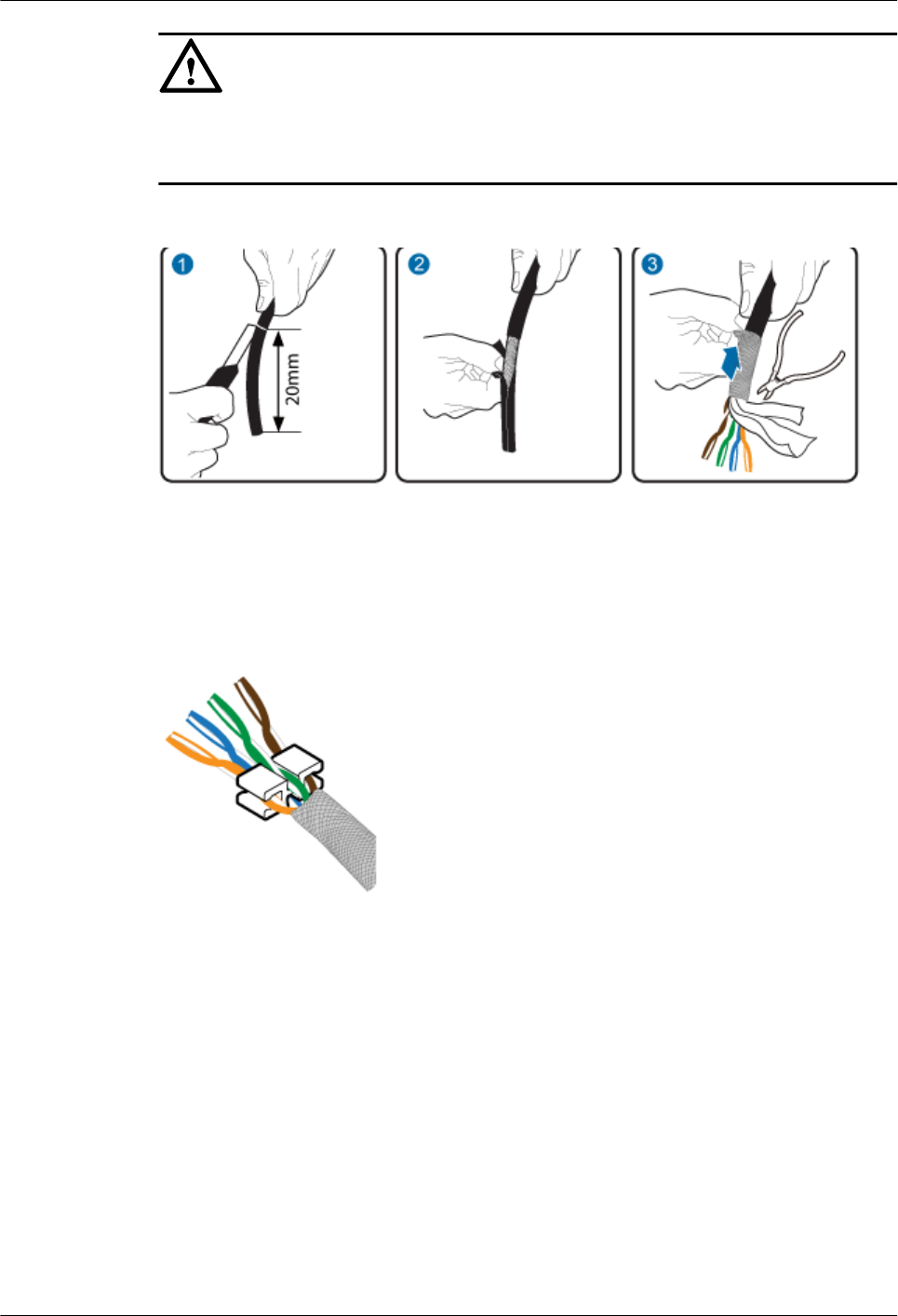
NOTICE
Ensure that the shielded layer is intact when stripping outer jackets off the network cable.
Keep the cable insulation intact when stripping the shielded layer.
Figure 5-50 Stripping the cable
Step 2 Arrange core wires in the order of colors shown in Figure 5-51 and fix the cable support rack
to the bottom of the core wires.
Figure 5-51 Core wire order
Step 3 Hold the arranged core wires and route them through the load bar, as shown in Figure 5-52.
Table 5-7 shows the mapping between the core wires and pins of the connector.
AP4050DN-E
Hardware Installation and Maintenance Guide 5 Appendix
Issue 05 (2018-02-02) Huawei Proprietary and Confidential
Copyright © Huawei Technologies Co., Ltd.
63
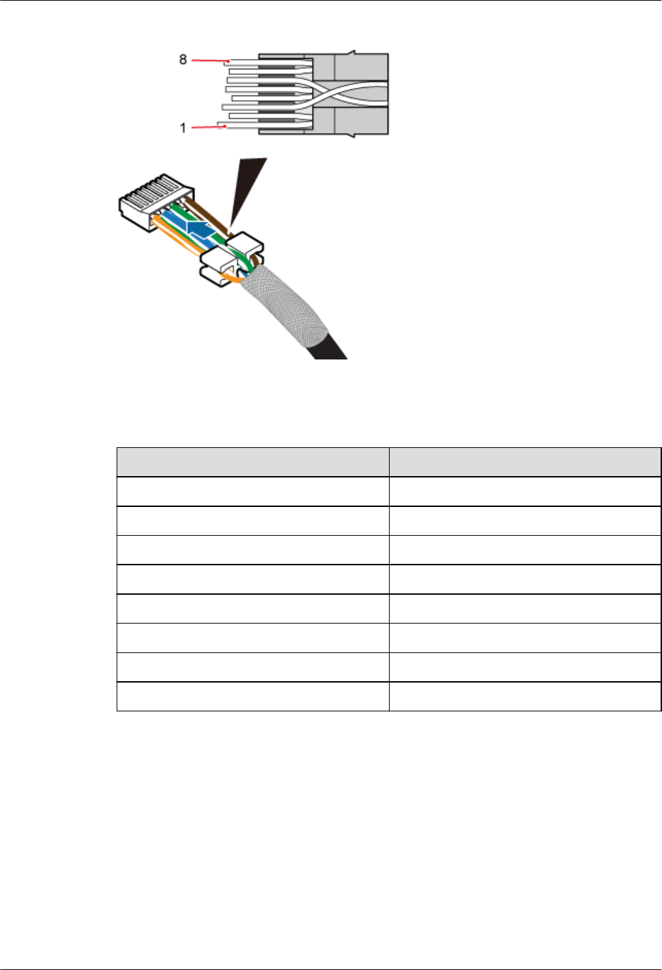
Figure 5-52 Routing the core wires through the load bar
Table 5-7 Mapping between core wires and pins
Pin ID Core Wire Color
1 White-orange
2 Orange
3 White-green
4 Blue
5 White-blue
6 Green
7 White-brown
8 Brown
Step 4 After routing core wires through the load bar, move the load bar to the bottom to connect to
the cable support rack, and neatly cut the edge cables, as shown in Figure 5-53.
AP4050DN-E
Hardware Installation and Maintenance Guide 5 Appendix
Issue 05 (2018-02-02) Huawei Proprietary and Confidential
Copyright © Huawei Technologies Co., Ltd.
64
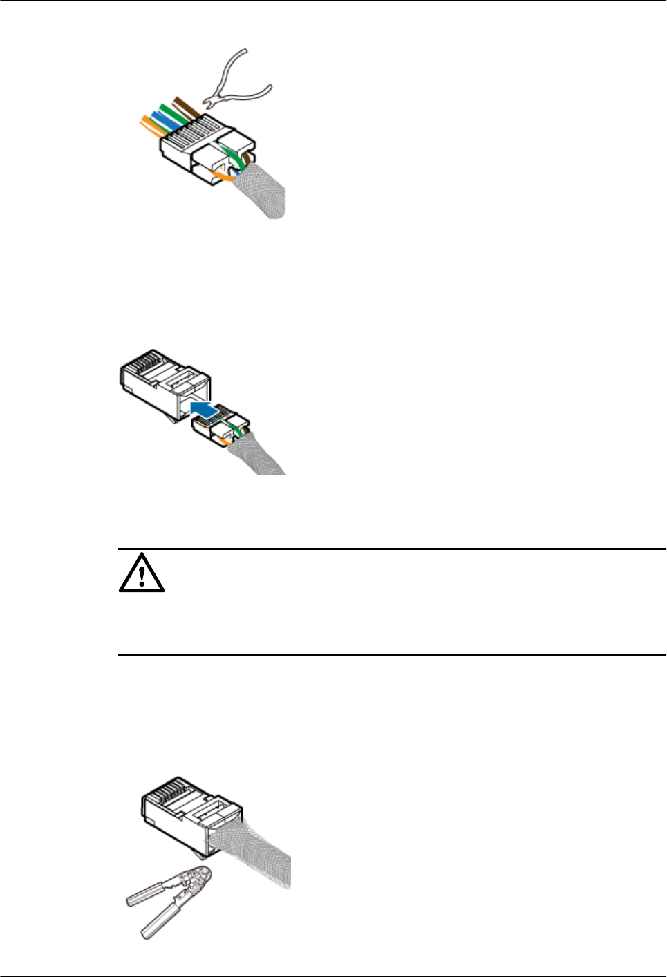
Figure 5-53 Neatly cutting edge cables
Step 5 Insert the load bar into the RJ45 connector, as shown in Figure 5-54.
Figure 5-54 Inserting the load bar into the RJ45 connector
NOTICE
Cables must be inserted into the bottom of the connector, which can be checked on the side or
front end face of the connector.
Step 6 Use the crimping tool to crimp the connector, as shown in Figure 5-55. Use cutting pliers to
neatly cut braid shields exposed out of the connector along the load bar, as shown in Figure
5-56.
Figure 5-55 Crimping the connector
AP4050DN-E
Hardware Installation and Maintenance Guide 5 Appendix
Issue 05 (2018-02-02) Huawei Proprietary and Confidential
Copyright © Huawei Technologies Co., Ltd.
65
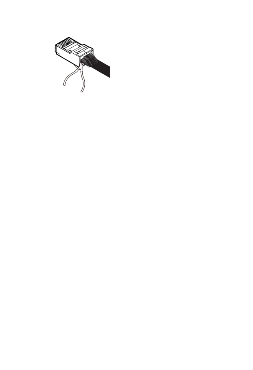
Figure 5-56 Neatly cutting braid shields
Step 7 Repeat Step 1 through Step 6 to assemble the optimized shielded RJ45 connector on the other
end of the network cable.
----End
5.1.3.3 Assembling an Integrated Shielded RJ45 Connector and SFTP Network
Cables
Context
This topic describes how to assemble an integrated shielded RJ45 connector with a Secure
File Transfer Protocol (SFTP) straight-through network cable as an example. The connector
does not have a cable support rack or metal jacket.
Figure 5-57 shows the integrated shielded RJ45 connector.
AP4050DN-E
Hardware Installation and Maintenance Guide 5 Appendix
Issue 05 (2018-02-02) Huawei Proprietary and Confidential
Copyright © Huawei Technologies Co., Ltd.
66
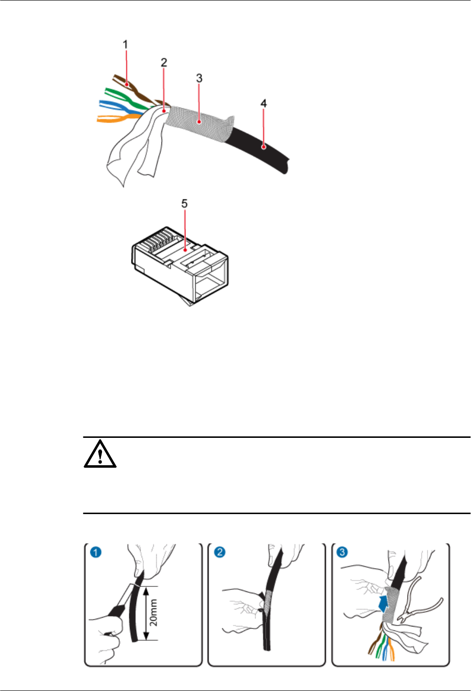
Figure 5-57 Shielded RJ45 connector
1: Core wires 2: Aluminum foil 3: Braid shield 4: Outer jacket 5: RJ45 connector
Procedure
Step 1 Strip 20 mm outer jacket off the network cable, peel off the braid shield backward, and cut off
the aluminum foil and protection band, as shown in Figure 5-58.
NOTICE
Ensure that the shielded layer is intact when stripping outer jackets off the network cable.
Keep the cable insulation intact when stripping the shielded layer.
Figure 5-58 Stripping the cable
AP4050DN-E
Hardware Installation and Maintenance Guide 5 Appendix
Issue 05 (2018-02-02) Huawei Proprietary and Confidential
Copyright © Huawei Technologies Co., Ltd.
67
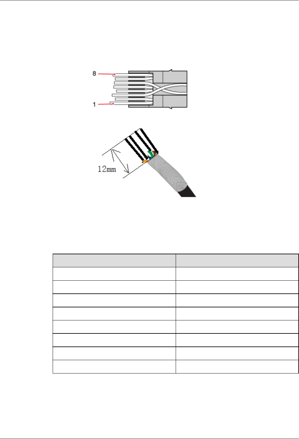
Step 2 Arrange the twisted pair wires in the order of colors shown in Table 5-8 and cut the wire ends
neatly with 12 mm core wires left, as shown in Figure 5-59.
Figure 5-59 Core wire order
Table 5-8 Mapping between core wires and pins
Pin ID Core Wire Color
1 White-orange
2 Orange
3 White-green
4 Blue
5 White-blue
6 Green
7 White-brown
8 Brown
Step 3 Route the arranged core wires through the RJ45 connector, as shown in Figure 5-60.
AP4050DN-E
Hardware Installation and Maintenance Guide 5 Appendix
Issue 05 (2018-02-02) Huawei Proprietary and Confidential
Copyright © Huawei Technologies Co., Ltd.
68
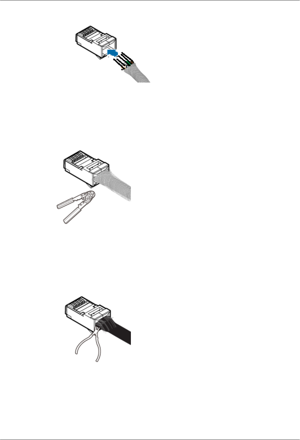
Figure 5-60 Routing core wires through the connector
Step 4 Use the crimping tool to crimp the connector, as shown in Figure 5-61.
Figure 5-61 Crimping the connector
Step 5 Neatly cut braid shields exposed out of the connector along the load bar, as shown in Figure
5-62.
Figure 5-62 Neatly cutting braid shields
Step 6 Repeat Step 1 through Step 5 to assemble the integrated shielded RJ45 connector on the other
end of the network cable.
----End
AP4050DN-E
Hardware Installation and Maintenance Guide 5 Appendix
Issue 05 (2018-02-02) Huawei Proprietary and Confidential
Copyright © Huawei Technologies Co., Ltd.
69
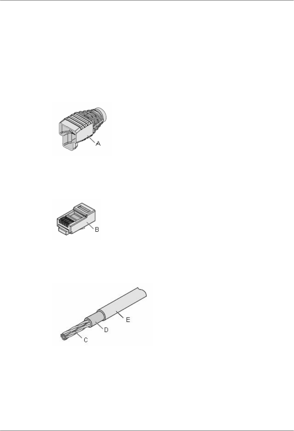
5.1.3.4 Assembling a Shielded RJ45 Connector and an FTP Network Cable
Context
This topic describes how to assemble a shielded RJ45 connector and File Transfer Protocol
(FTP) network cable and related notes.
Figure 5-64 shows the shielded RJ45 connector.
Figure 5-63 Connector jacket
Figure 5-64 Shielded RJ45 connector
Figure 5-65 Cable
A: Connector
jacket
B: Connector C: Core wires of the
twisted pair
D: Aluminum foil used as the
network cable shield
E: Network cable
jacket
Procedure
Step 1 Route the network cable through the connector jacket, as shown in Figure 5-66.
AP4050DN-E
Hardware Installation and Maintenance Guide 5 Appendix
Issue 05 (2018-02-02) Huawei Proprietary and Confidential
Copyright © Huawei Technologies Co., Ltd.
70
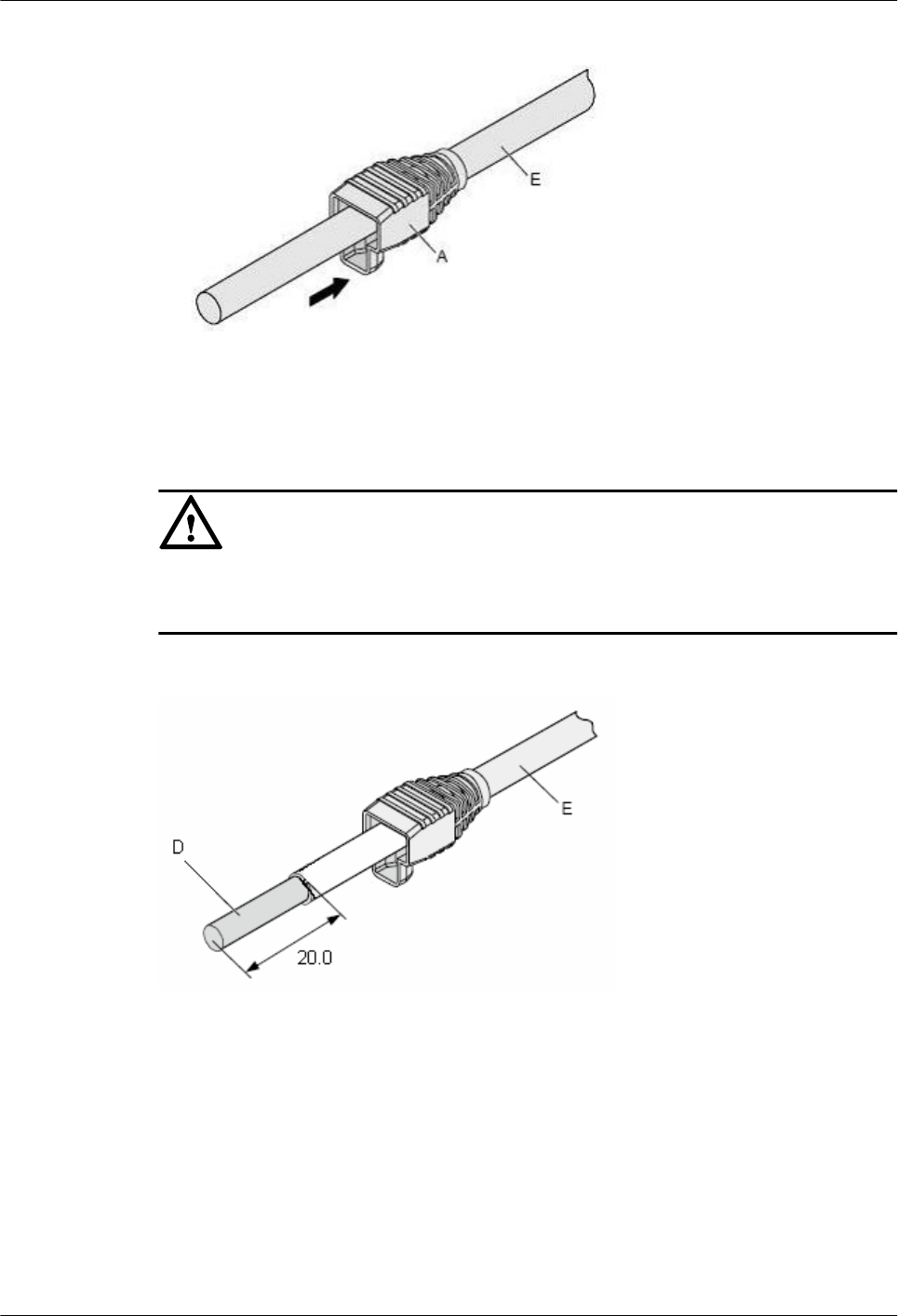
Figure 5-66 Routing the network cable through the connector jacket
Step 2 Strip 20 mm outer jacket off the cable and cut off the nylon layer inside the jacket, as shown
in Figure 5-67.
NOTICE
Ensure that the aluminum foil used as a shielded layer is intact when stripping outer jackets
off the twisted pair cable.
Figure 5-67 Stripping the outer jacket
Step 3 Pull outward the shielded aluminum foil and cut off the PET membrane and ground cables
along the end face of the outer jacket, as shown in Figure 5-68.
AP4050DN-E
Hardware Installation and Maintenance Guide 5 Appendix
Issue 05 (2018-02-02) Huawei Proprietary and Confidential
Copyright © Huawei Technologies Co., Ltd.
71
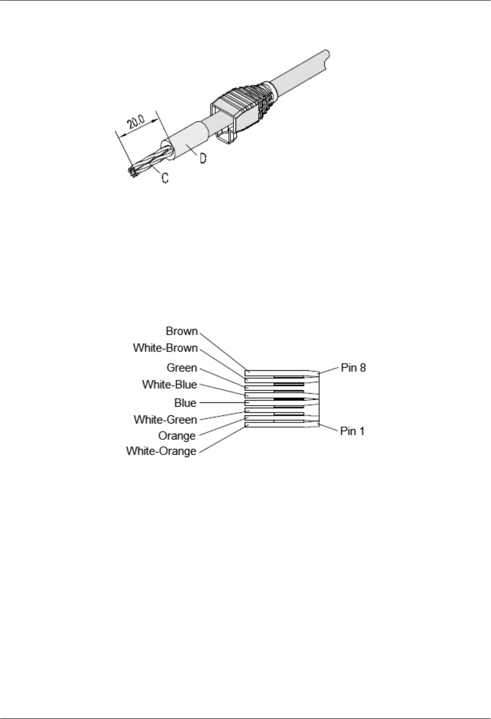
Figure 5-68 Cutting off the PET membrane and ground cables
Step 4 Arrange the twisted core wires according to color order shown in Figure 5-69. Use cutting
pliers to neatly cut the front end of the twisted pair, as shown in Figure 5-70. Figure 5-71
shows pin arrangement of each contact of the connector.
Figure 5-69 Mapping between colors and pins
AP4050DN-E
Hardware Installation and Maintenance Guide 5 Appendix
Issue 05 (2018-02-02) Huawei Proprietary and Confidential
Copyright © Huawei Technologies Co., Ltd.
72
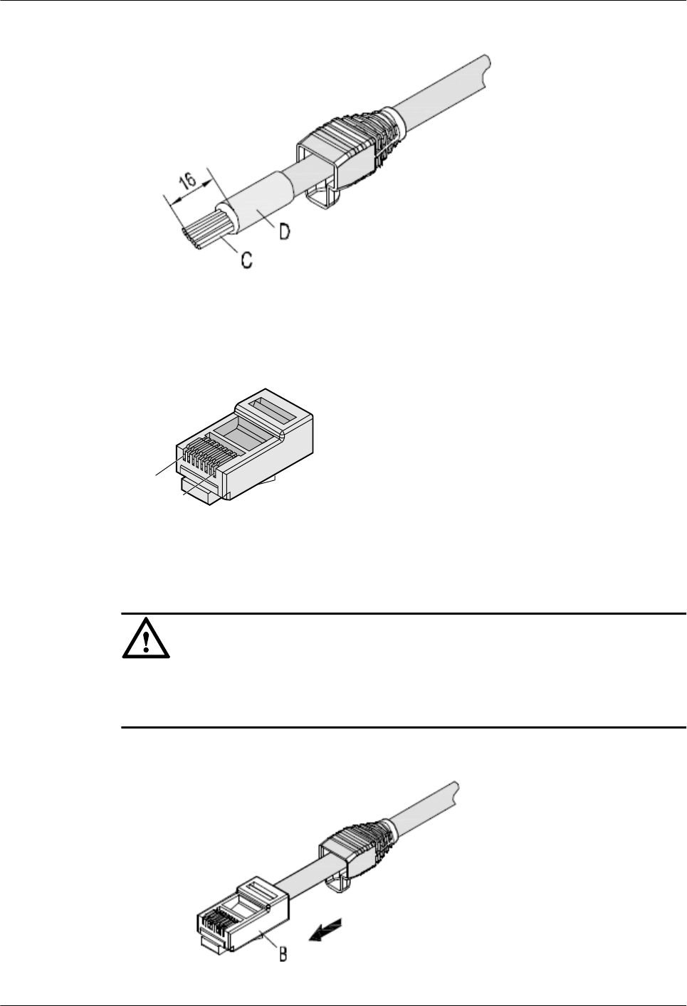
Figure 5-70 Neatly cutting the twisted pair
Figure 5-71 Pin arrangement of the connector
Pin8
Pin1
Step 5 Insert the arranged four twisted pair cables into the connector, as shown in Figure 5-72.
NOTICE
lCables must be inserted into the bottom.
lThe aluminum foil must keep intact after cables are inserted into the connector.
Figure 5-72 Inserting cables into the connector
AP4050DN-E
Hardware Installation and Maintenance Guide 5 Appendix
Issue 05 (2018-02-02) Huawei Proprietary and Confidential
Copyright © Huawei Technologies Co., Ltd.
73
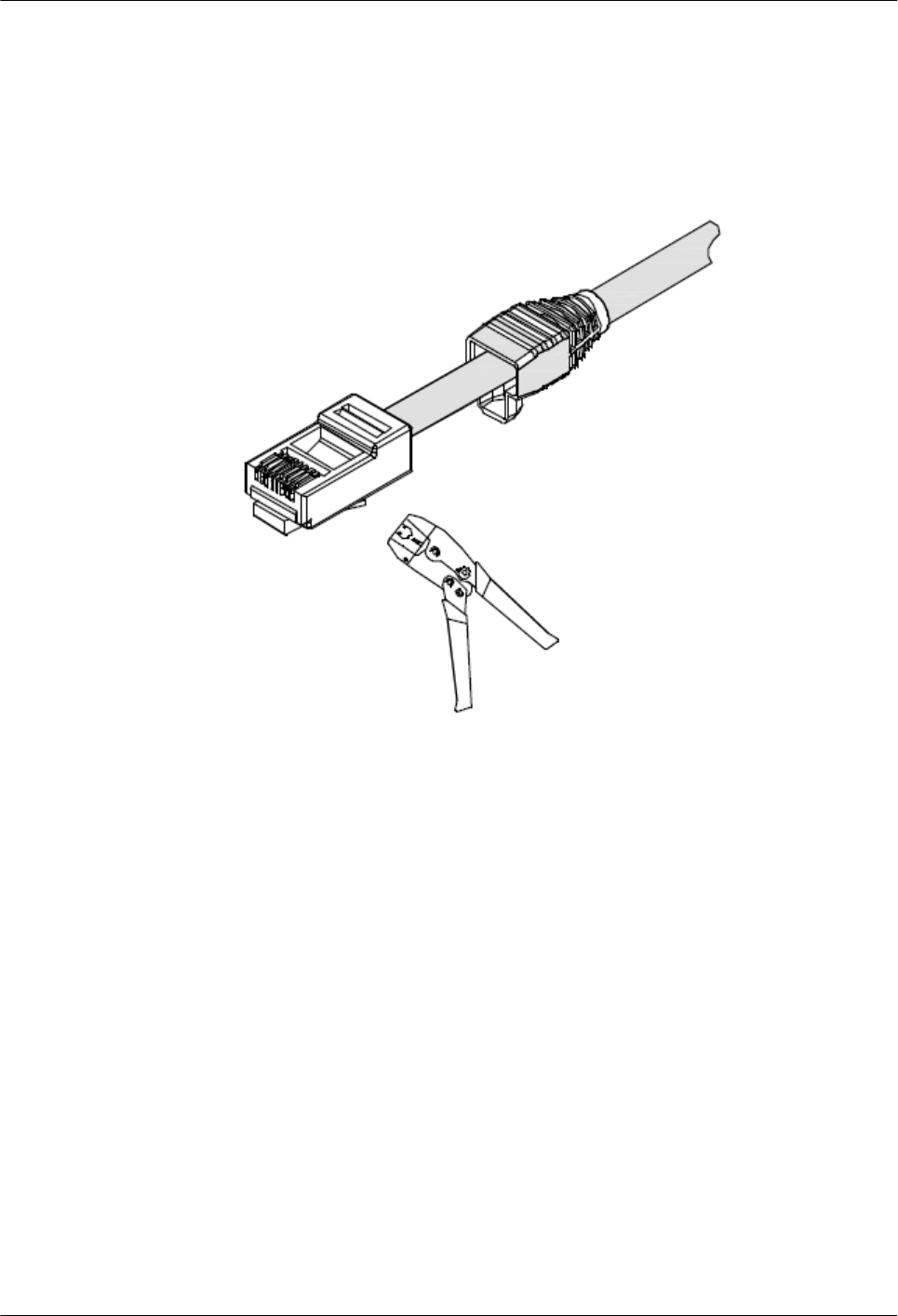
Step 6 Use the crimping tool dedicated for FTP network cables to crimp the connector and neatly cut
the aluminum foil along the end face of the connector, as shown in Figure 5-73.
Figure 5-73 Crimping the connector
Step 7 Move the connector jacket to the connector body to wrap the connector shell, as shown in
Figure 5-74.
AP4050DN-E
Hardware Installation and Maintenance Guide 5 Appendix
Issue 05 (2018-02-02) Huawei Proprietary and Confidential
Copyright © Huawei Technologies Co., Ltd.
74
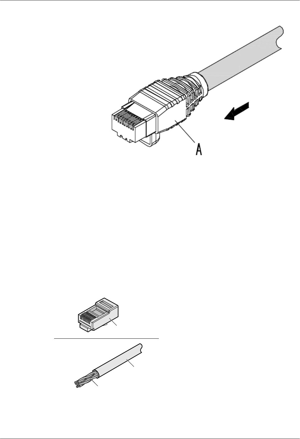
Figure 5-74 Wrapping the connector shell
Step 8 Repeat Step 1 through Step 7 to assemble the shielded RJ45 connector on the other end of the
network cable.
----End
5.1.3.5 Assembling an Unshielded RJ45 Connector and Ethernet Cable
Context
Figure 5-75 shows the components of an unshielded RJ45 connector and cable.
Figure 5-75 Components of an unshielded RJ45 connector and cable
A
B
C
A. Plug of connector B. Jacket C. Twisted-pair wires
AP4050DN-E
Hardware Installation and Maintenance Guide 5 Appendix
Issue 05 (2018-02-02) Huawei Proprietary and Confidential
Copyright © Huawei Technologies Co., Ltd.
75
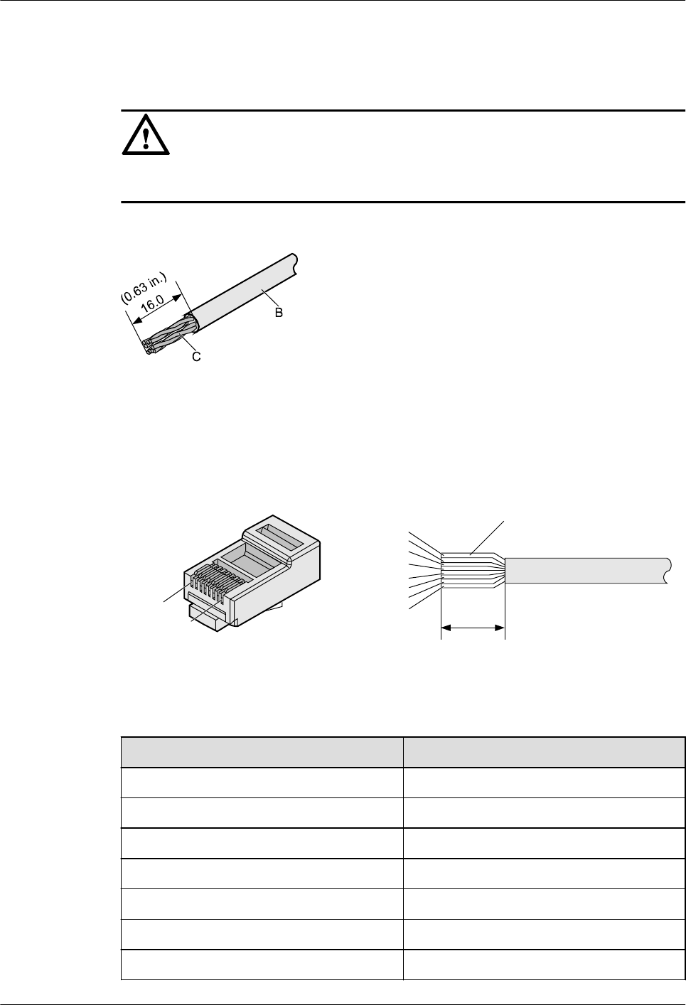
Procedure
Step 1 Remove a 16-mm (0.63 in.) long section of the jacket, as shown in Figure 5-76.
NOTICE
When you remove the shield layer, do not damage the insulation of the twisted-pair cable.
Figure 5-76 Removing the jacket of a twisted-pair cable (unit: mm (in.))
Step 2 Align the four pairs of wires and cut the ends neatly, as shown in Figure 5-77. The
connections between the wires and the pins are listed in Table 5-9.
Figure 5-77 Connections between wires and pins (unit: mm (in.))
C
16
White-Orange
White-Green
Orange
Blue
White-Blue
Green
White-Brown
Brown
Pin 8
Pin 1
Table 5-9 Connections between wires and pins (using a straight-through cable as an example)
Matching Pins of Wires Wire Color
1 White-Orange
2 Orange
3 White-Green
4 Blue
5 White-Blue
6 Green
7 White-Brown
AP4050DN-E
Hardware Installation and Maintenance Guide 5 Appendix
Issue 05 (2018-02-02) Huawei Proprietary and Confidential
Copyright © Huawei Technologies Co., Ltd.
76
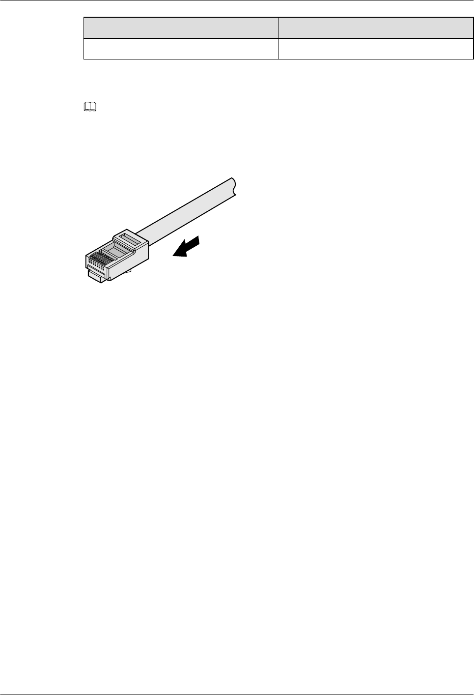
Matching Pins of Wires Wire Color
8 Brown
Step 3 Feed the cable into the plug, and crimp the connector, as shown in Figure 5-78.
NOTE
When inserting the cable, check from the side or bore of the plug to ensure that the cable is completely
seated in the plug.
Figure 5-78 Crimping the connector
Step 4 To complete the assembly of the other end, repeat steps 1 to 3.
----End
5.1.3.6 Checking the Appearance of Contact Strips
Context
lTo ensure proper contact between the crimped wires and the wire conductors, the heights
and sizes of the contact strips must be standard and the same.
lThe contact strips must be parallel to each other, with an offset of less than ± 5°. The top
margin of a strip must be parallel to the axis of the connector, with an offset of less than
± 10°.
lTo ensure conductivity, the surface of the contact strips must be clean.
lThe contact strips must be in good contact with the RJ45 socket. The plastic separators
must remain intact and be aligned.
lThe contact strip blade must extend beyond the ends of the wires. The ends of the wires
must be in contact with the edge of the RJ45. The distance between them must be less
than 0.5 mm (0.02 in.).
Procedure
Step 1 Hold the crimped connector, with the front side facing you, and check whether the contact
strips are of the same height. The height should be 6.02 ± 0.13 mm (0.237 ± 0.005). If a
measuring tool is not available, you can compare the connector with a standard connector.
Figure 5-79 shows an unqualified piece, and Figure 5-80 shows a qualified piece.
AP4050DN-E
Hardware Installation and Maintenance Guide 5 Appendix
Issue 05 (2018-02-02) Huawei Proprietary and Confidential
Copyright © Huawei Technologies Co., Ltd.
77
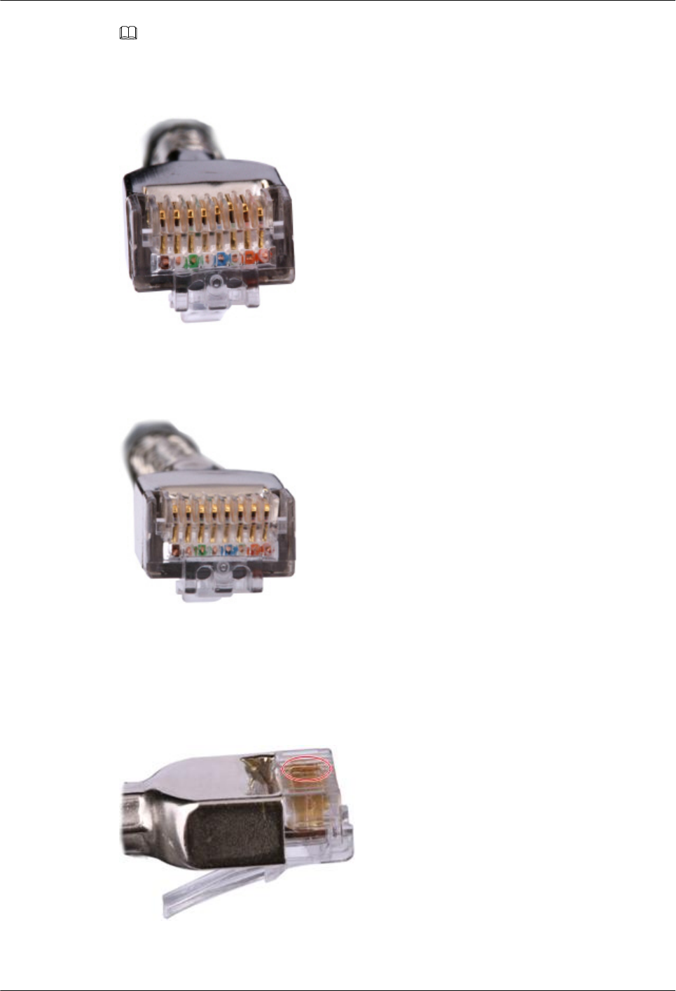
NOTE
All unqualified pieces must be crimped again.
Figure 5-79 Contact strips of different heights
Figure 5-80 Contact strips of the same height
Step 2 Hold an RJ45 connector and turn it 45°. Observe the top edges of the metal contact strips.
Figure 5-81 shows an unqualified piece.
Figure 5-81 Unparallel contact strips of different heights
AP4050DN-E
Hardware Installation and Maintenance Guide 5 Appendix
Issue 05 (2018-02-02) Huawei Proprietary and Confidential
Copyright © Huawei Technologies Co., Ltd.
78
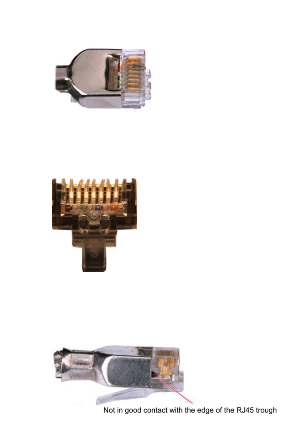
Step 3 Check whether the contact strips are clean. If they are not clean and the dirt cannot be
removed, replace it with a new RJ45 connector. Figure 5-82 shows an unqualified piece.
Figure 5-82 Dirt on a contract strip
Step 4 Check whether the contact strips and the plastic separators are well aligned and intact. If a
separator is skewed and cannot be fixed, replace it with a new RJ45 connector. Figure 5-83
shows an unqualified piece.
Figure 5-83 Skewed plastic separators
Step 5 Hold the connector with the side facing towards you, and check whether you can see the
cross-sections of the wires. Ensure that the ends of the wires are in good contact with the edge
of the RJ45, and that the contact strip blade extends beyond the ends of the wires and is
crimped with the wires. If not, replace the connector. Figure 5-84 shows an unqualified piece.
Figure 5-84 Wires not in good contact with the edge of the RJ45
AP4050DN-E
Hardware Installation and Maintenance Guide 5 Appendix
Issue 05 (2018-02-02) Huawei Proprietary and Confidential
Copyright © Huawei Technologies Co., Ltd.
79

----End
5.1.3.7 Testing the Connection of Assembled Cables
Context
Huawei provides two types of Ethernet cables: straight-through cables and crossover cables.
lStraight-through cables are connected in a one-to-one manner. They are used to connect
terminals such as a computer or switch to network devices. Table 5-10 lists the
connections of core wires in a straight-through cable.
Table 5-10 Connections of core wires in a straight-through cable
RJ45 Connector 1 RJ45 Connector 2 Core Wire Color Twisted or Not
2 2 Orange Twisted
1 1 Orange-White
6 6 Green Twisted
3 3 Green-White
4 4 Blue Twisted
5 5 Blue-White
8 8 Brown Twisted
7 7 Brown-White
lCrossover cables are connected in a crossover manner. They are used to connect
terminals such as two computers or switches. Table 5-11 lists the connections of core
wires in a crossover cable.
Table 5-11 Connections of core wires in a straight crossover cable
RJ45 Connector 1 RJ45 Connector 2 Core Wire Color Twisted or Not
6 2 Orange Twisted
3 1 Orange-White
2 6 Green Twisted
1 3 Green-White
4 4 Blue Twisted
5 5 Blue-White
8 8 Brown Twisted
AP4050DN-E
Hardware Installation and Maintenance Guide 5 Appendix
Issue 05 (2018-02-02) Huawei Proprietary and Confidential
Copyright © Huawei Technologies Co., Ltd.
80
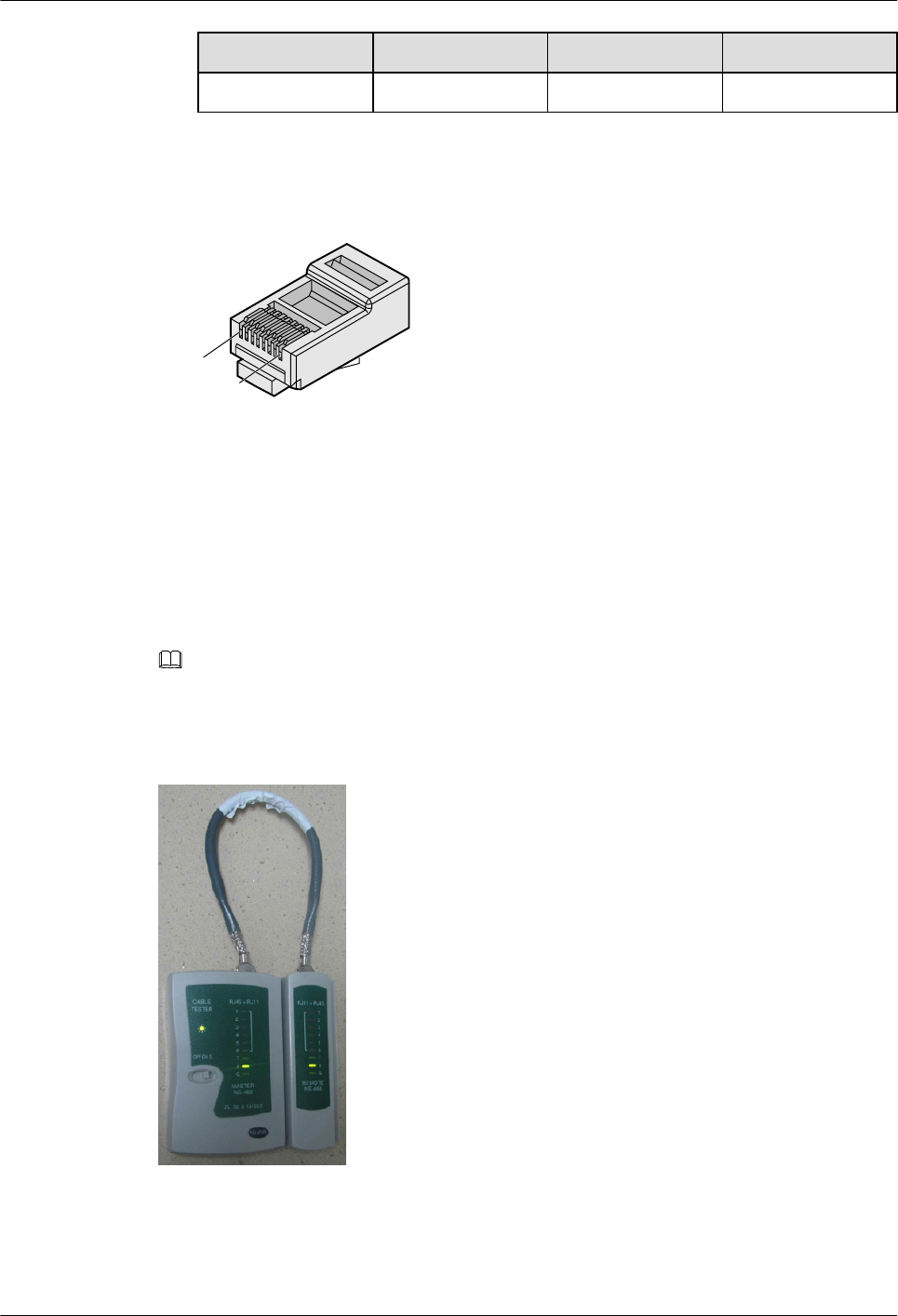
RJ45 Connector 1 RJ45 Connector 2 Core Wire Color Twisted or Not
7 7 Brown-White
Figure 5-85 shows the pins of an RJ45 connector.
Figure 5-85 Pins of an RJ45 connector
Pin8
Pin1
Procedure
Step 1 Feed both connectors of the cable into the ports of the cable tester.
Step 2 After the connectors are properly inserted, turn on the tester. If the indicators from 1 to G turn
on simultaneously, you can infer that the pins work normally and the wires are correctly
connected.
NOTE
Turn the switch to the S position to slow down lighting of the indicators so that you can see the
indicators more clearly, as shown in Figure 5-86.
Figure 5-86 Testing the conduction and connections of wires
Step 3 Gently shake the connector and repeat Step 2 to check whether the metal contact strips are in
good contact with the core wires and Ethernet ports, as shown in Figure 5-87.
AP4050DN-E
Hardware Installation and Maintenance Guide 5 Appendix
Issue 05 (2018-02-02) Huawei Proprietary and Confidential
Copyright © Huawei Technologies Co., Ltd.
81
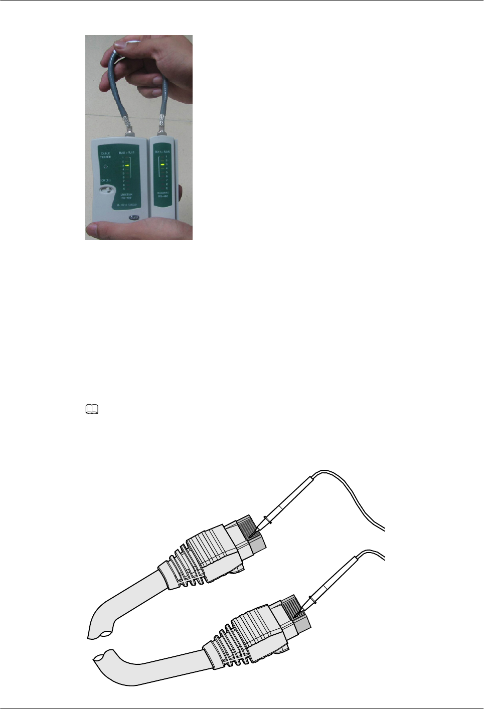
Figure 5-87 Checking the reliability
The procedure for testing a crossover cable is the same as that for testing a straight-through
cable except for the sequence in which the indicators turn on, which depends on the wire
connections of a crossover cable.
The Ethernet cable is qualified if the indicators turn on in the following sequence:
At the master (left) section of the tester, the indicators turn on in the sequence of 1-8-G. At the
slave (right) section of the tester, the indicators turn on in the sequence of 3-6-1-4-5-2-7-8-G.
If the indicators do not come on in this sequence, the Ethernet cable is unqualified.
NOTE
If a tester is not available, you can use a multimeter to perform a simple test, as shown in Figure 5-88.
Figure 5-88 Testing the connection of an Ethernet cable
AP4050DN-E
Hardware Installation and Maintenance Guide 5 Appendix
Issue 05 (2018-02-02) Huawei Proprietary and Confidential
Copyright © Huawei Technologies Co., Ltd.
82

----End
5.1.3.8 Common Network Cable Faults and Preventive Measures
Table 5-12 lists common network cable faults and preventive measures.
Table 5-12 Common network cable faults and preventive measures
Symptom Cause Preventive Measure
lThe device cannot be
powered using PoE.
lThe device restarts
frequently.
lA large number of error
packets exist on the
device or services are
interrupted.
A network cable has high
resistance or is too long.
Before using network cables
purchased from other
suppliers, use a multimeter
or other tools to measure
cable resistance. Replace the
network cables if their
resistance does not conform
to PoE standard
requirements for network
cable quality.
Non-standard network cable
connectors cause poor
contact with device
interfaces.
Before making a network
cable, use a standard go-no
go gauge to test the
connectors purchased from
other suppliers. Replace the
connectors if they do not
comply with the standard.
Wires in a network cable are
connected to wrong pins.
After a network cable is
made, use a conduction
tester to measure cable
connectivity. For test details,
see 5.1.3.7 Testing the
Connection of Assembled
Cables.
A network cable connector
is not crimped securely,
causing poor contact
between the network cable
and pins in the connector.
When testing a network
cable with a conduction
tester, gently shake the cable
connector and check
whether indicators on the
conduction tester are in
normal state. If indicators 1
to G turn on in a wrong
sequence, remake the
network cable.
The following methods are often used to test network cable resistance, and the test criteria are
listed in Table 5-13:
AP4050DN-E
Hardware Installation and Maintenance Guide 5 Appendix
Issue 05 (2018-02-02) Huawei Proprietary and Confidential
Copyright © Huawei Technologies Co., Ltd.
83
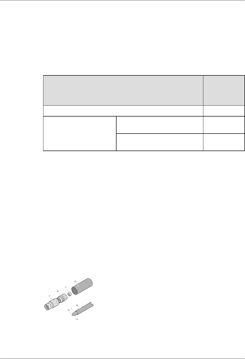
lUse a network cable tester (high-end cable tester of Fluke) to measure network cable
resistance.
lConnect multimeter probes to two ends of each wire in a network cable and check the
resistance value on the multimeter.
lConnect a network cable to an AP. Use a multimeter to test the resistance between pins 1
and 2 (or between pins 3 and 6, 4 and 5, or 7 and 8) on the other end of the cable. The
cable's DC resistance approximately equals a half of the displayed value.
Table 5-13 PoE standard requirements for network cable quality
Standard Total
Resistance of
a Network
Cable
802.3af ≤ 20 ohms
802.3at Maximum PD power consumption <
12.95 W
≤ 20 ohms
Maximum PD power consumption <
25.5 W
≤ 12.5 ohms
If an AP is connected to a switch or AC (excluding ACU2), you can run the virtual-cable-
test command on the switch or AC to check network cable connectivity. For details, see the
virtual-cable-test command in the command reference.
5.1.4 Assembling Feeders
5.1.4.1 Assembling the Straight Male Coaxial N Connector and the 1/2'' Feeder
Context
Figure 5-89 shows the components of an N coaxial connector and a 1/2" feeder cable.
Figure 5-89 Components of an N coaxial connector and a 1/2" feeder cable
A. Body of connector B. Back shell of connector C. O-ring seal D. Heat-shrink tubing
E. Cable jacket F. Outer conductor of feeder
cable
G. Inner conductor of
feeder cable
H. Insulation layer of
feeder cable
AP4050DN-E
Hardware Installation and Maintenance Guide 5 Appendix
Issue 05 (2018-02-02) Huawei Proprietary and Confidential
Copyright © Huawei Technologies Co., Ltd.
84
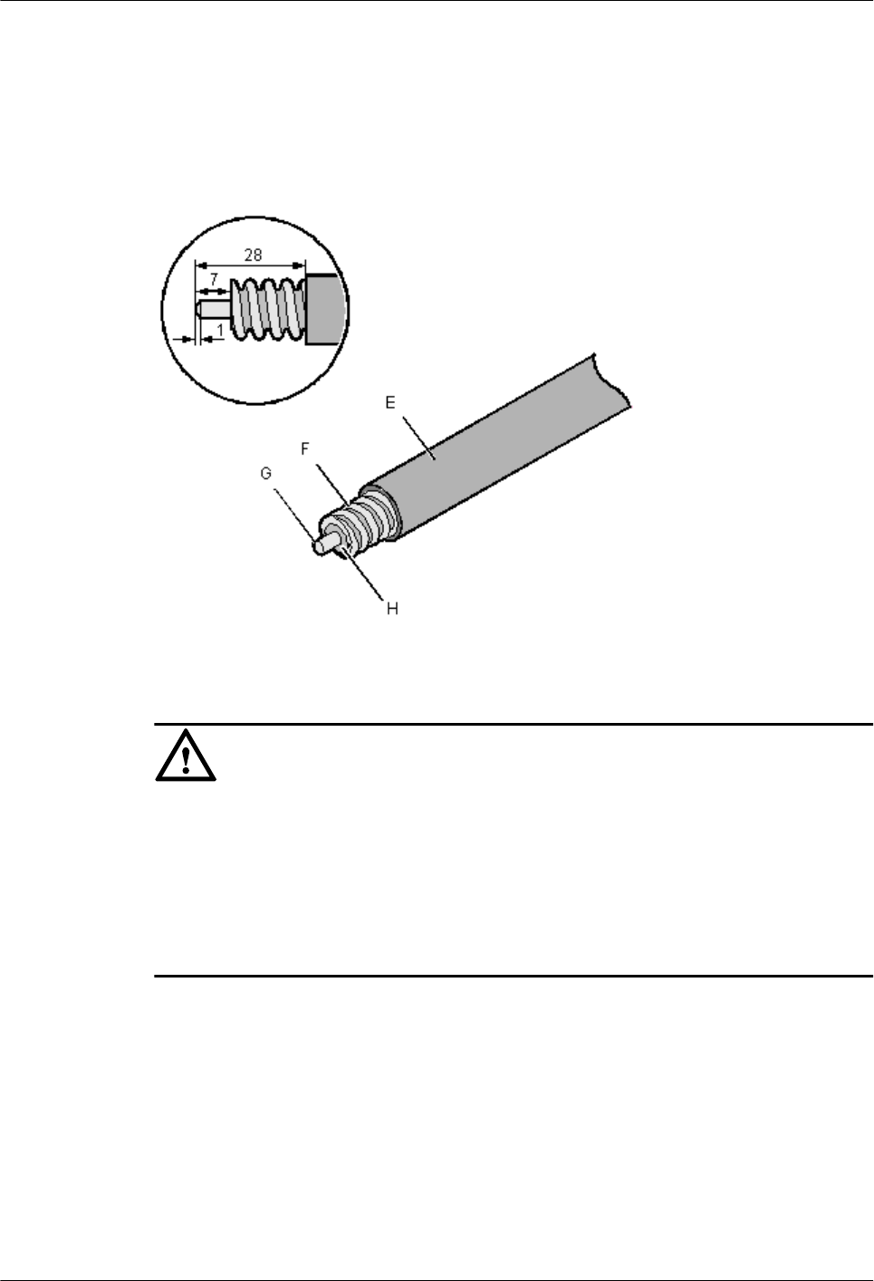
Procedure
Step 1 Cut the feeder cable, as shown in Figure 5-90.
Figure 5-90 Cutting a feeder cable (unit: mm)
NOTICE
lEnsure that the feeder cable is cut with reference to the guide in the package box of the
connector.
lAfter you cut the feeder cable, ensure that the cross-section of the outer conductor is
smooth, intact, and round.
lEnsure that the feeder cable is cut at the wave crest of the outer conductor.
lThe inner conductor must be beveled, as shown in Figure 5-90.
Step 2 Use a brush to remove the dirt on the cross-section of the feeder cable.
Step 3 Feed the feeder cable into the heat-shrink tubing, and cover the outer conductor of the feeder
cable with the O-ring seal, as shown in Figure 5-91.
AP4050DN-E
Hardware Installation and Maintenance Guide 5 Appendix
Issue 05 (2018-02-02) Huawei Proprietary and Confidential
Copyright © Huawei Technologies Co., Ltd.
85
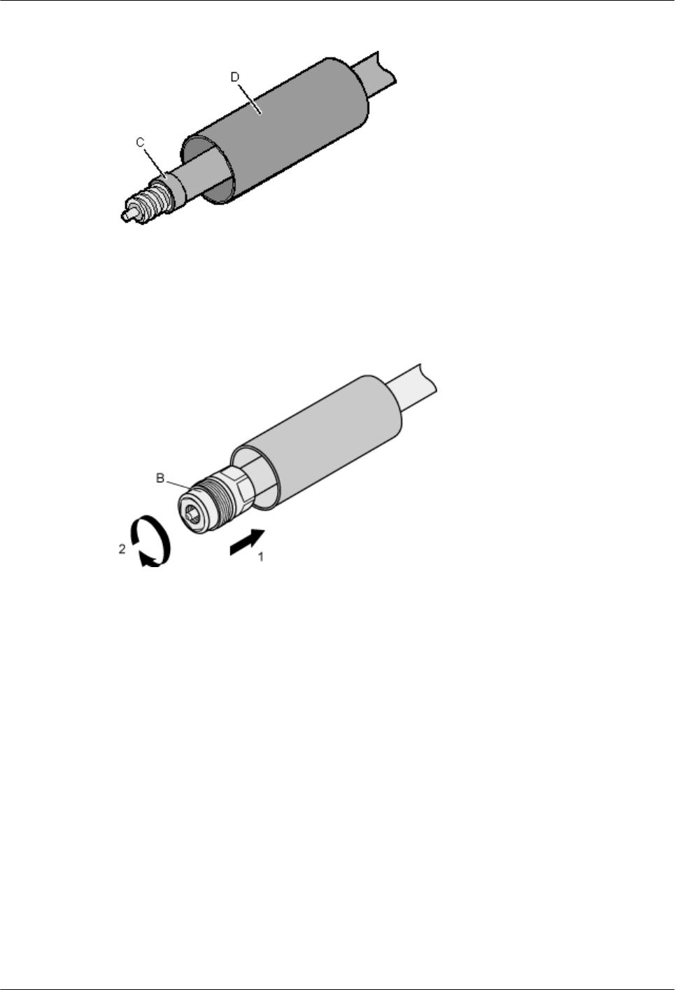
Figure 5-91 Installing the heat-shrink tubing and the O-ring seal
Step 4 Put the back shell of the connector onto the feeder cable. Tighten the back shell to the end of
the feeder cable, as shown in Figure 5-92.
Figure 5-92 Putting the back shell of the connector onto the feeder cable
Step 5 Mount the body of the connector onto the feeder cable so that the inner conductors of the
connector and feeder cable are connected. Use a spanner (27 N•m to 30 N•m torque
recommended) to fasten the body and back shell, as shown in Figure 5-93.
AP4050DN-E
Hardware Installation and Maintenance Guide 5 Appendix
Issue 05 (2018-02-02) Huawei Proprietary and Confidential
Copyright © Huawei Technologies Co., Ltd.
86
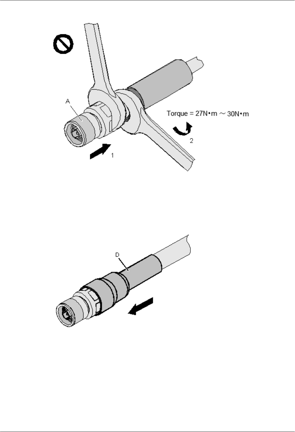
Figure 5-93 Fastening the body and back shell
Step 6 Push the heat-shrink tubing towards the connector, as shown in Figure 5-94. Then, heat the
tube.
Figure 5-94 Assembled N connector
Step 7 After the components are assembled, install the connector, as shown in Figure 5-95.
AP4050DN-E
Hardware Installation and Maintenance Guide 5 Appendix
Issue 05 (2018-02-02) Huawei Proprietary and Confidential
Copyright © Huawei Technologies Co., Ltd.
87
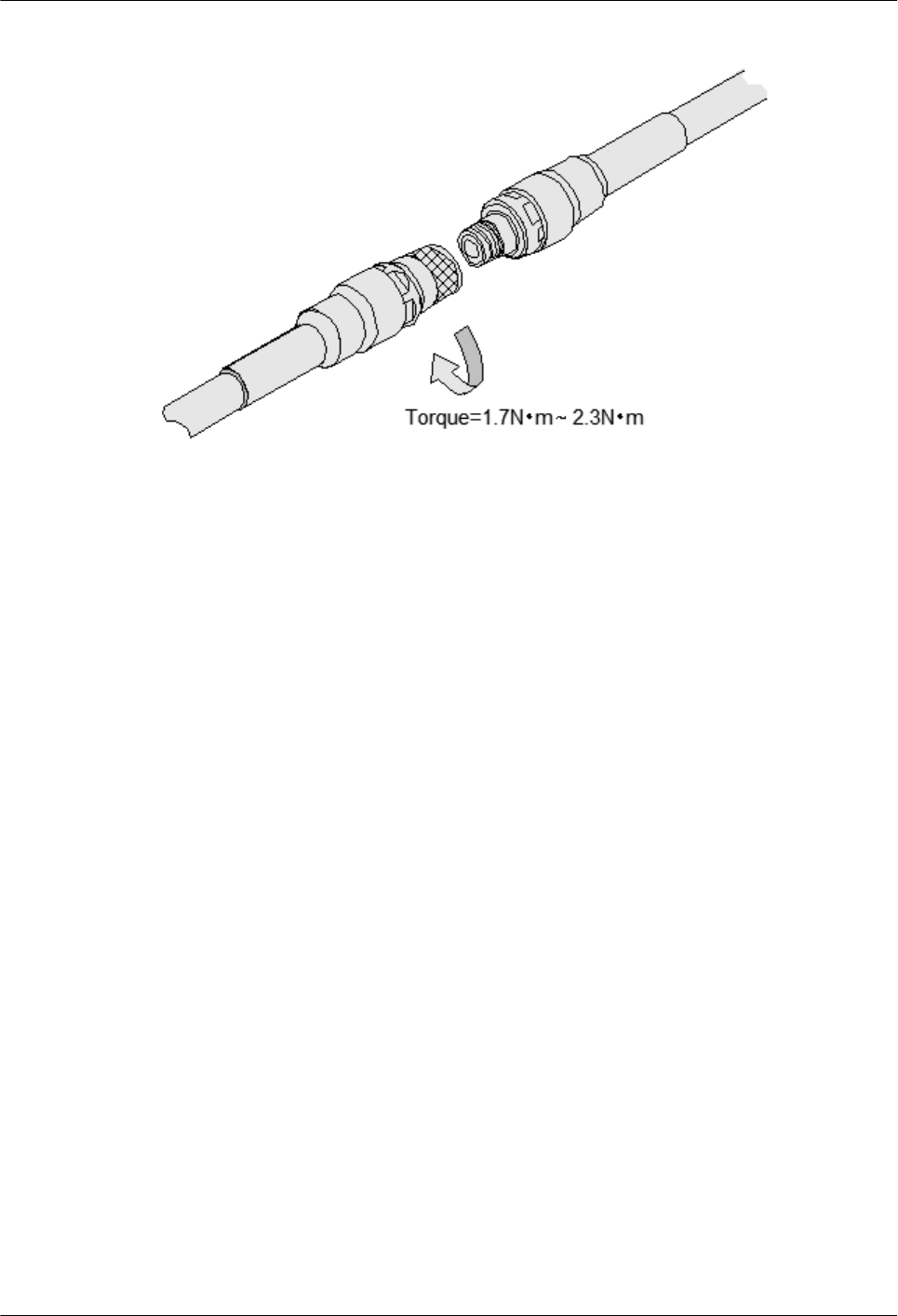
Figure 5-95 Installing the connector
----End
5.1.4.2 Assembling a Straight Male Coaxial N Connector and an RG8U Feeder
Context
Figure 5-96 shows the coaxial N connector and RG8U feeder.
AP4050DN-E
Hardware Installation and Maintenance Guide 5 Appendix
Issue 05 (2018-02-02) Huawei Proprietary and Confidential
Copyright © Huawei Technologies Co., Ltd.
88
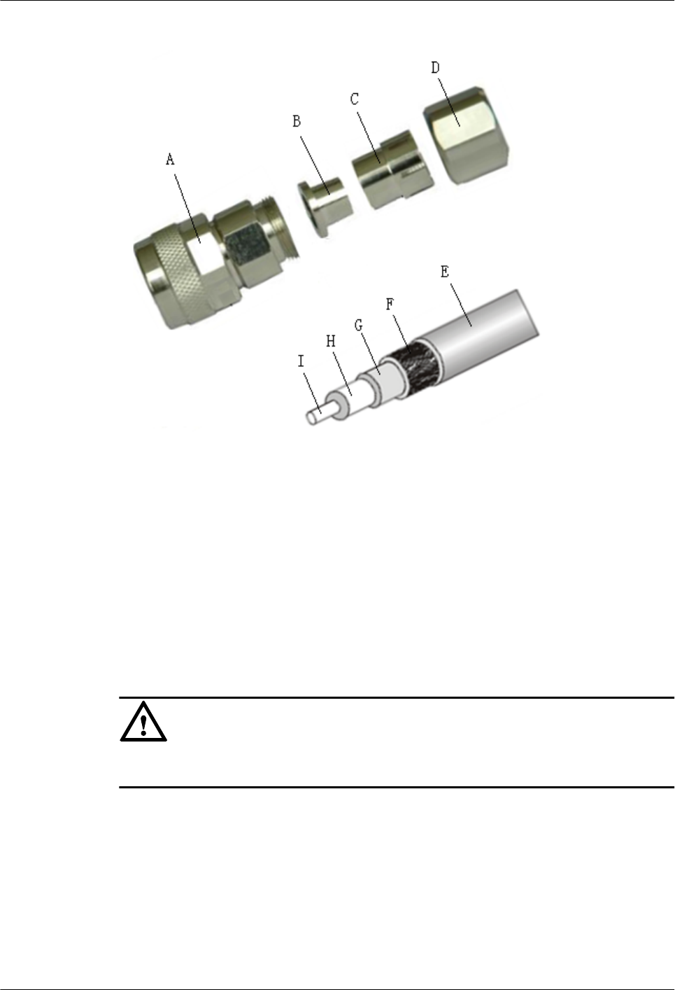
Figure 5-96 Coaxial N connector and RG8U feeder
A: Connector body B: Lining C: Clip D: Nut
E: Cable jacket F: Shielded layer of the
feeder
G: Aluminum foil of the
feeder
H: Insulation medium of
the feeder
I: Internal conductor of the
feeder
- - -
Procedure
Step 1 Strip the feeder with the length shown in Figure 5-97.
NOTICE
Ensure that the shielded layer F is intact after the stripping.
AP4050DN-E
Hardware Installation and Maintenance Guide 5 Appendix
Issue 05 (2018-02-02) Huawei Proprietary and Confidential
Copyright © Huawei Technologies Co., Ltd.
89
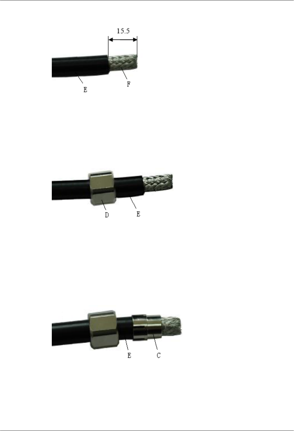
Figure 5-97 Stripping the feeder
Step 2 Route the Cable jacket (E) through the nut (D), as shown in Figure 5-98.
Figure 5-98 Installing the nut
Step 3 Install the clip (C) on the Cable jacket (E) and move the clip until the clip is close to the Cable
jacket, as shown in Figure 5-99.
Figure 5-99 Installing the clip
Step 4 Peel off the shielded layer (F) to the direction of the clip (C) so that the aluminum foil (G) is
exposed, as shown in Figure 5-100.
AP4050DN-E
Hardware Installation and Maintenance Guide 5 Appendix
Issue 05 (2018-02-02) Huawei Proprietary and Confidential
Copyright © Huawei Technologies Co., Ltd.
90
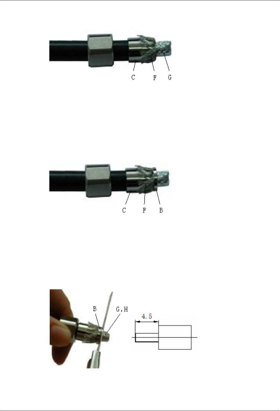
Figure 5-100 Peeling off the shielded layer
Step 5 Install the lining (B) on the feeder and tightly crimp the shielded layer (F) of the feeder, as
shown in Figure 5-101.
Figure 5-101 Installing the lining
Step 6 Cut off the aluminum foil (G) and insulation medium (H) along the end face of the lining (B).
Ensure that the length of the conducting line inside the feeder is 4.5 mm, as shown in Figure
5-102.
Figure 5-102 Cutting off the aluminum foil and insulation medium of the feeder
Step 7 Use the file to taper the internal conductor (I) of the feeder, as shown in Figure 5-103.
AP4050DN-E
Hardware Installation and Maintenance Guide 5 Appendix
Issue 05 (2018-02-02) Huawei Proprietary and Confidential
Copyright © Huawei Technologies Co., Ltd.
91
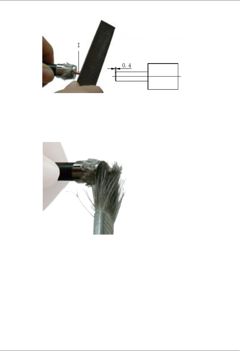
Figure 5-103 Tapering the internal conductor of the feeder
Step 8 Use a brush to remove impurities from the cross section of the feeder, as shown in Figure
5-104.
Figure 5-104 Clearing impurities
Step 9 Insert the half-finished part into the main body of the connector (A) and rotate the nut (D) and
the connector's main body until you cannot rotate further, as shown in Figure 5-105.
AP4050DN-E
Hardware Installation and Maintenance Guide 5 Appendix
Issue 05 (2018-02-02) Huawei Proprietary and Confidential
Copyright © Huawei Technologies Co., Ltd.
92
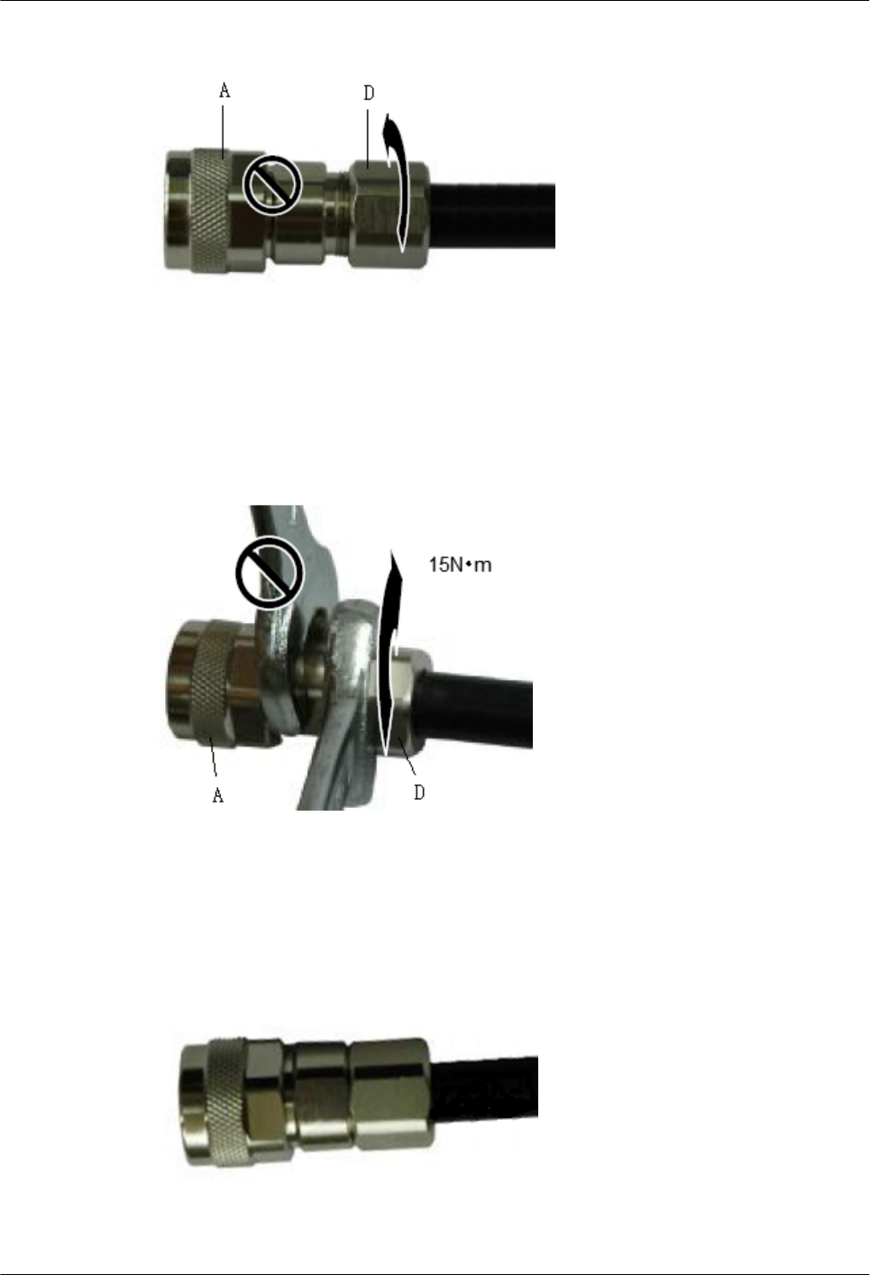
Figure 5-105 Installing the connector's main body
Step 10 Use a wrench to fix the nut (D) to connector's main body (A) with recommended tightening
torque 15 N•m, as shown in Figure 5-106.
Figure 5-106 Fixing the nut to the connector shell body
Step 11 Figure 5-107 shows the effect drawing after the assembling is complete.
Figure 5-107 Effect drawing of the straight male coaxial N connector
AP4050DN-E
Hardware Installation and Maintenance Guide 5 Appendix
Issue 05 (2018-02-02) Huawei Proprietary and Confidential
Copyright © Huawei Technologies Co., Ltd.
93
----End
5.1.5 Installing Cable Accessories
5.1.5.1 Precautions for Installing Cable Accessories
Tools
NOTE
The illustrations in this document may differ from actual situations, but the installation methods are the
same. For example, in this document, the adapters of cable connectors have separate interfaces. In the
actual situation, the adapters may have interfaces fixed on equipment.
Use dedicated tools provided or specified by Huawei and follow the installation procedure
described here.
Bending Radius
Unless otherwise specified, bending radius (R) of cables or fibers must meet the requirements
listed in Table 5-14.
Table 5-14 Bending radius of cables or fibers
Cable or Fiber Bending Radius (R)
Ordinary cable In normal cases, R ≥ 2d. When the cable is
connected with a connector, R ≥ 5d.
Fiber R ≥ 40 mm (1.57 in.); Bending angle > 90°
NOTE
The letter d indicates the diameter of a cable or fiber.
Precautions for Installation
lHold terminals of cables instead of pulling the cables themselves when installing or
removing cable components.
lDo not insert a connector forcibly when the connector is blocked. Use a dedicated tool to
pull out the connector. Install the connector again after you check that the pins are
inserted properly.
lBefore tightening screws on cable connectors, ensure that the connectors are properly
connected to their adapters. Tighten the screw with appropriate force using a flat-head or
Phillips screwdriver instead of bare hands or an electric screwdriver. If the screw cannot
be screwed into the tapped hole, determine the reason and try again. Do not apply too
much force, or the screw or adapter may be damaged.
lWhen removing densely aligned cables or fiber connectors, use dedicated pliers such as
cable-pulling pliers and fiber-pulling pliers.
AP4050DN-E
Hardware Installation and Maintenance Guide 5 Appendix
Issue 05 (2018-02-02) Huawei Proprietary and Confidential
Copyright © Huawei Technologies Co., Ltd.
94
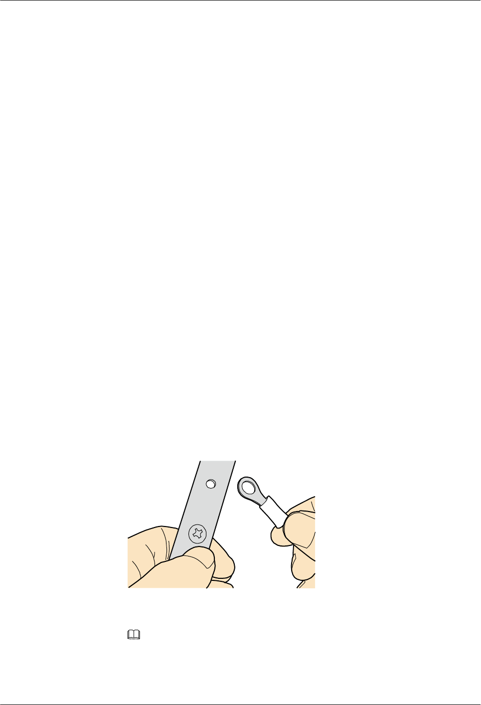
lDo not twist, bend, stretch, or extrude fibers during installation.
lCover the idle fiber connectors with dust caps. Remove the dust caps before using the
fiber connectors.
Requirements for Cable Routing
lTo protect cables, remove the burrs in the cable through-holes or install protective rings
in the holes.
lTo ease the connection and to avoid stress, keep cable joints slack. After connecting
multiple cables to a connector that has multiple interfaces, keep the cables slack to avoid
generating stress.
lBind or clean cables gently because cable distortion affects signal quality.
lKeep cables away from moveable components such as doors.
lSharp objects must not touch cable wiring to prevent damage to cables.
lTo protect power cables, route power cables of the active and standby power modules
separately.
5.1.5.2 Installing Power Adapters
5.1.5.2.1 Installing the OT Terminal
Procedure
lInstall an OT terminal.
a. Align the hole of the OT terminal (conductor upward) with a connecting hole, as
shown in Figure 5-108.
Figure 5-108 Aligning the OT terminal with a connecting hole
NOTE
When you install an OT terminal, the crimping sleeve is installed as shown in Figure 5-109,
where A is correct and B is incorrect.
AP4050DN-E
Hardware Installation and Maintenance Guide 5 Appendix
Issue 05 (2018-02-02) Huawei Proprietary and Confidential
Copyright © Huawei Technologies Co., Ltd.
95
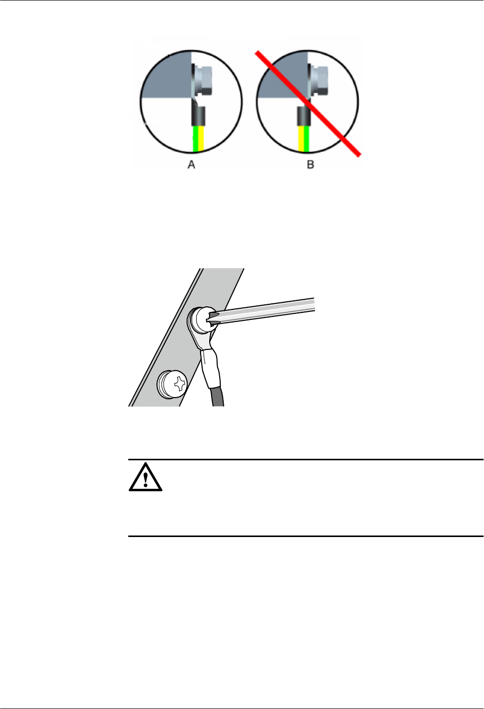
Figure 5-109 Installing an OT terminal, showing the orientation of crimping sleeve
b. Place the spring washer and flat washer in turn, mount a matching screw, and fasten
it clockwise, as shown in Figure 5-110.
Figure 5-110 Installing two terminals back to back
NOTICE
Ensure that the OT terminal is not in contact with other terminals or metal
components.
c. Move the cable slightly and ensure that it is securely connected, as shown in Figure
5-111.
AP4050DN-E
Hardware Installation and Maintenance Guide 5 Appendix
Issue 05 (2018-02-02) Huawei Proprietary and Confidential
Copyright © Huawei Technologies Co., Ltd.
96
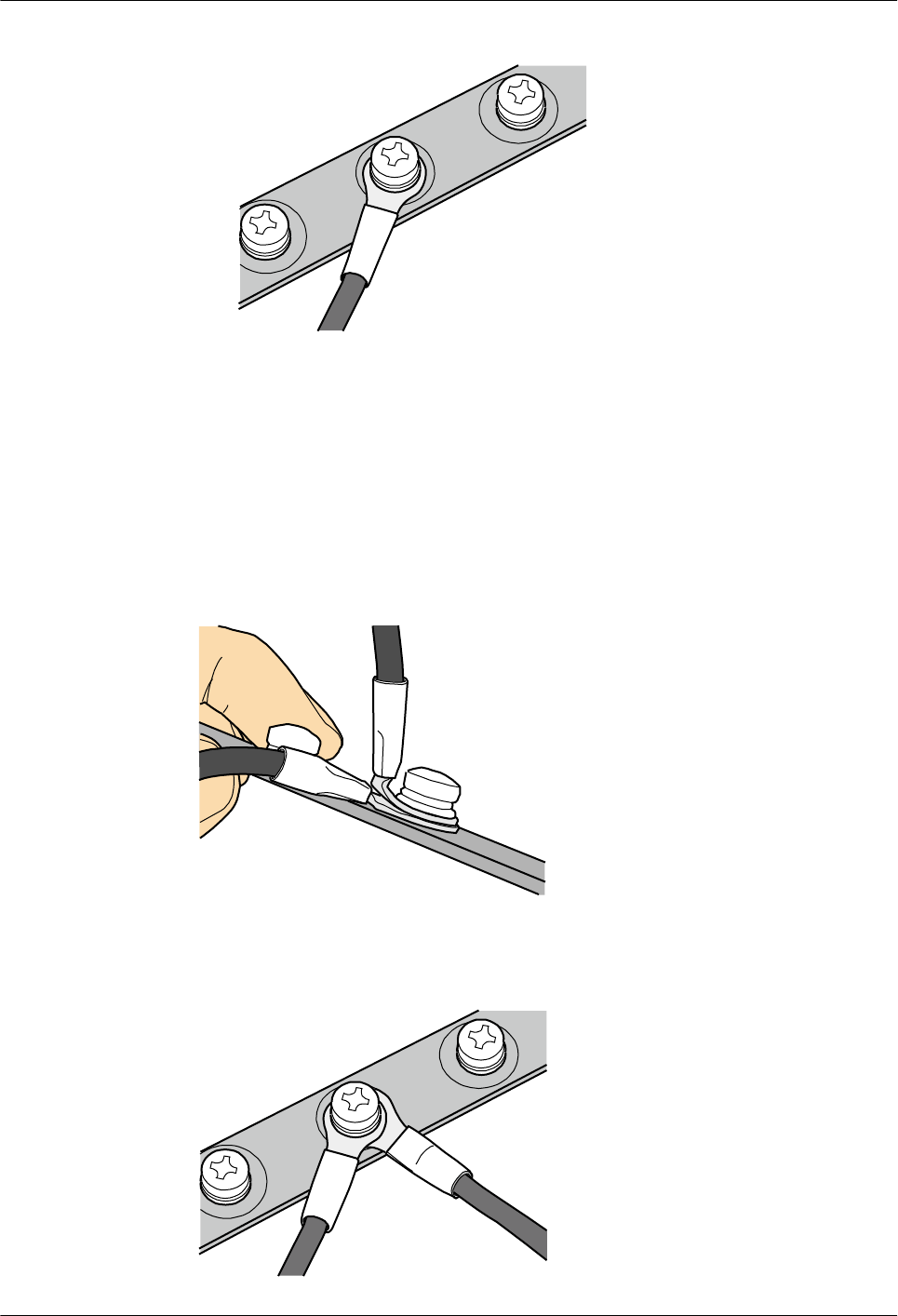
Figure 5-111 Installed OT terminal
lInstall two OT terminals on a post.
Before you install two OT terminals on a post, ensure that the two terminals can be
installed on the post and that the electrical connecting pieces have a large contact area.
Two OT terminals can be installed using any of these methods:
–Bend the upper OT terminal at a 45- or 90-degree angle, as shown in Figure 5-112.
–Cross the two terminals, as shown in Figure 5-113.
Figure 5-112 Bending the upper OT terminal at a 45- or 90-degree angle
Figure 5-113 Crossing two terminals
AP4050DN-E
Hardware Installation and Maintenance Guide 5 Appendix
Issue 05 (2018-02-02) Huawei Proprietary and Confidential
Copyright © Huawei Technologies Co., Ltd.
97
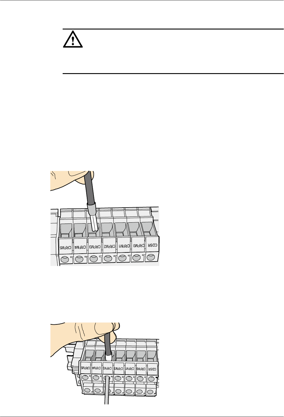
NOTICE
If the two terminals are different sizes, place the smaller one above the bigger one. A
maximum of two terminals can be installed on a post.
lTo remove an OT terminal, loosen the screw counterclockwise.
----End
5.1.5.2.2 Installing the Cord End Terminal
Procedure
Step 1 Hold a cord end terminal upright and place it on a terminal jack, as shown in Figure 5-114. To
ensure bump contact and dense connection, place the plain side of the terminal outwards.
Figure 5-114 Placing a terminal on a terminal jack vertically
Step 2 Insert the terminal into the jack vertically, and turn the screw clockwise to fasten the terminal,
as shown in Figure 5-115.
Figure 5-115 Feeding the terminal into the jack
AP4050DN-E
Hardware Installation and Maintenance Guide 5 Appendix
Issue 05 (2018-02-02) Huawei Proprietary and Confidential
Copyright © Huawei Technologies Co., Ltd.
98
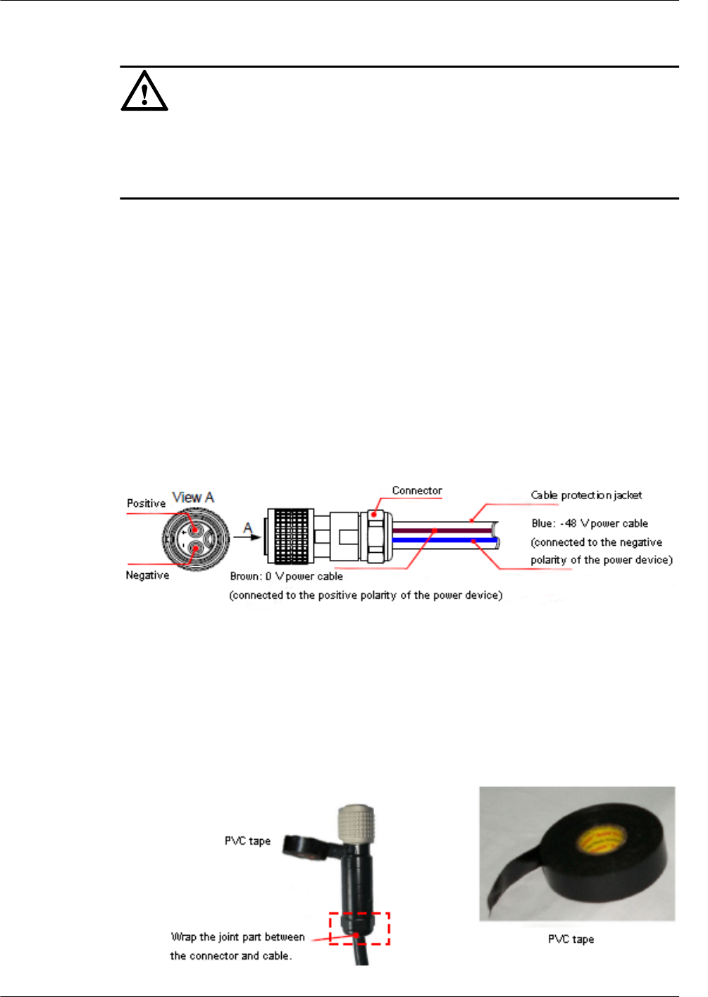
NOTICE
lEnsure that the exposed section of the terminal is less than 2 mm (0.079 in.) in length.
lDo not press the insulation of the terminal.
lInsert only one terminal into one jack.
Step 3 Move the cable slightly and ensure that it is securely connected.
Step 4 Before you remove a cord end terminal, loosen the screw counterclockwise.
----End
5.1.5.2.3 Installing a 2-Pin Round Connector and a DC Power Cable
This topic describes how to install a 2-pin round connector and a DC power cable and related
notes.
Context
Figure 5-116 shows the 2-pin round connector with a DC power cable.
Figure 5-116 2-pin round connector and a DC power cable
Procedure
Step 1 Waterproof cables to be connected.
1. Wrap a layer of PVC tape, as shown in Figure 5-117.
Figure 5-117 Wrapping the PVC tape
AP4050DN-E
Hardware Installation and Maintenance Guide 5 Appendix
Issue 05 (2018-02-02) Huawei Proprietary and Confidential
Copyright © Huawei Technologies Co., Ltd.
99
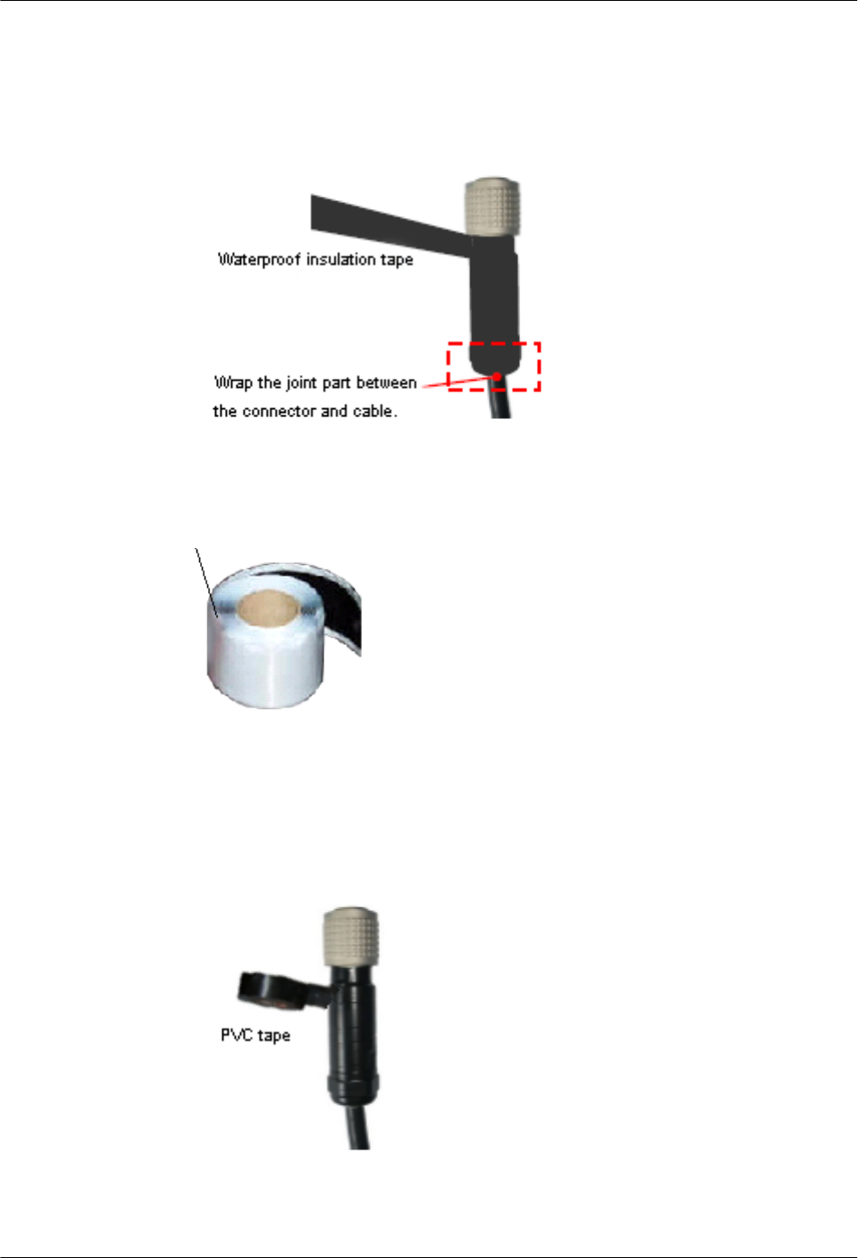
2. Wrap three layers of insulation tape, as shown in Figure 5-118.
Figure 5-118 Wrapping three layers of the waterproof insulation tape
Figure 5-119 Waterproof insulation tape
3. Wrap three layers of the PVC tape around the waterproof insulation tape, as shown in
Figure 5-120.
Figure 5-120 Wrapping three layers of the PVC tape
AP4050DN-E
Hardware Installation and Maintenance Guide 5 Appendix
Issue 05 (2018-02-02) Huawei Proprietary and Confidential
Copyright © Huawei Technologies Co., Ltd.
100
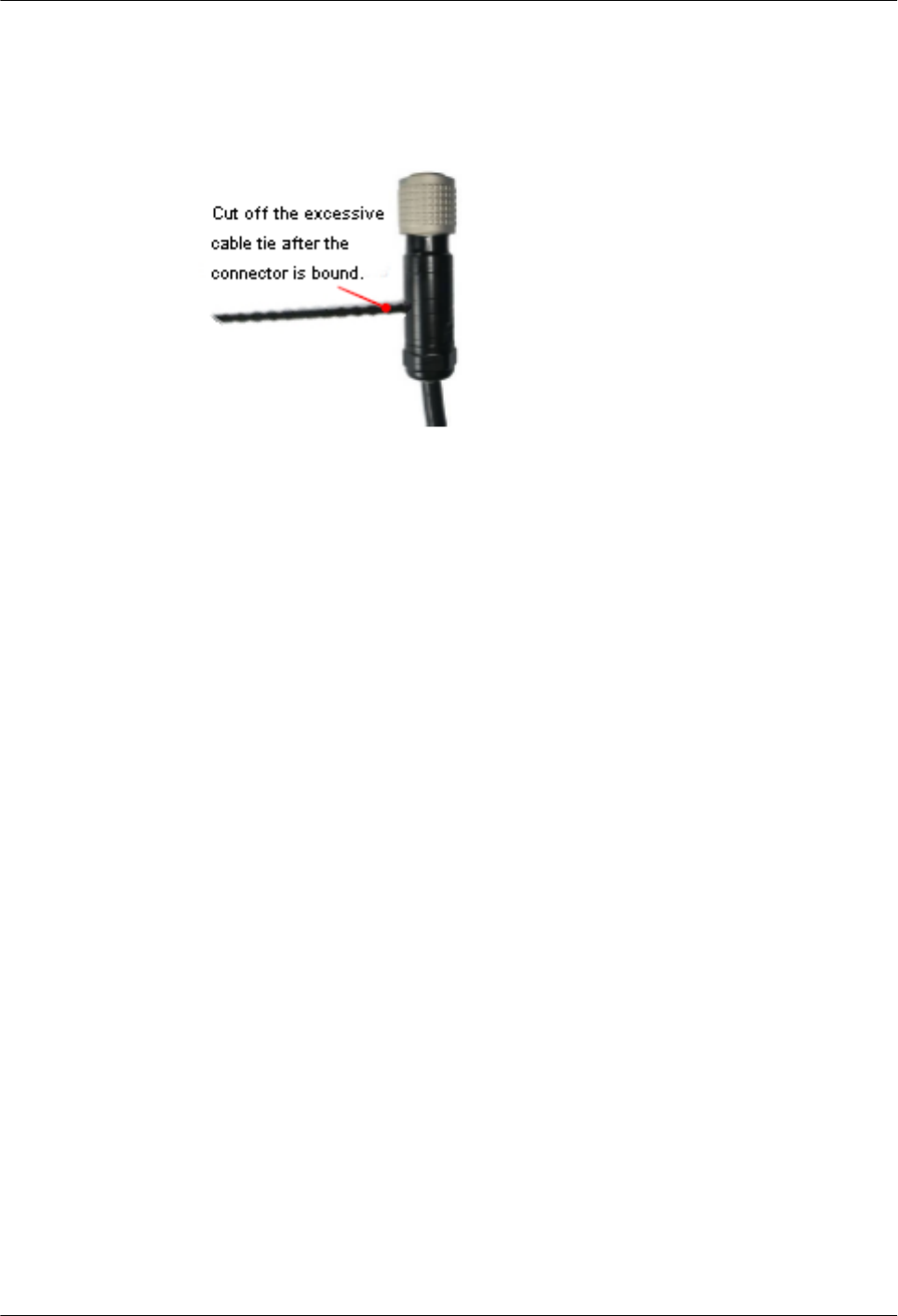
4. Tightly bind the PVC tape at the ends of the wrapping section, as shown in Figure
5-121.
Figure 5-121 Tightly binding the PVC tape
Step 2 Fix the DC power cable connector to the PWR port, as shown in Figure 5-122. Ensure that
positive and negative polarities are correct during the installation.
AP4050DN-E
Hardware Installation and Maintenance Guide 5 Appendix
Issue 05 (2018-02-02) Huawei Proprietary and Confidential
Copyright © Huawei Technologies Co., Ltd.
101
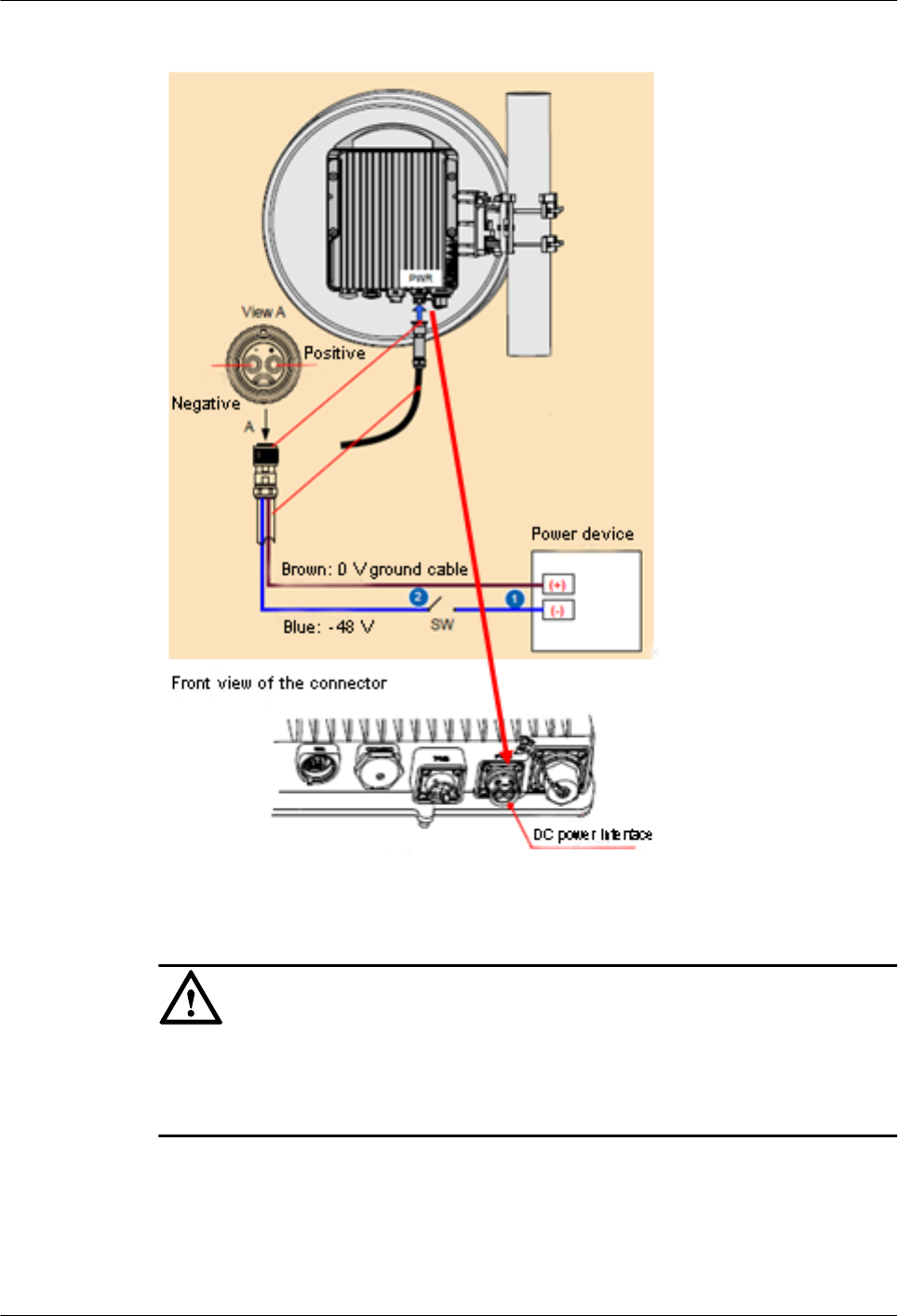
Figure 5-122 Installing the round connector
NOTICE
Use the outdoor binding strap to bind cables under the DC power cable connector for weight
bearing, preventing the DC power cable connector from being pulled. Reserve the proper
cable length between the binding point and the PWR port.
----End
5.1.5.3 Installing Ethernet Adapters
AP4050DN-E
Hardware Installation and Maintenance Guide 5 Appendix
Issue 05 (2018-02-02) Huawei Proprietary and Confidential
Copyright © Huawei Technologies Co., Ltd.
102
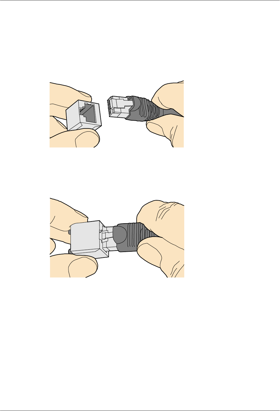
5.1.5.3.1 Installing a Shielded Ethernet Connector
Procedure
Step 1 Hold the male and female connectors, with the male connector facing the female connector, as
shown in Figure 5-123.
Figure 5-123 Holding the male and female shielded connectors
Step 2 Insert the male connector into the female connector, as shown in Figure 5-124.
Figure 5-124 Feeding the male shielded connector into the female shielded connector
Step 3 When you hear a click, the cable connector is completely inserted in the port. (The clip on the
cable connector pops up to fix the connector in the port.) Pull the connector slightly and
ensure that it is securely connected, as shown in Figure 5-125.
AP4050DN-E
Hardware Installation and Maintenance Guide 5 Appendix
Issue 05 (2018-02-02) Huawei Proprietary and Confidential
Copyright © Huawei Technologies Co., Ltd.
103
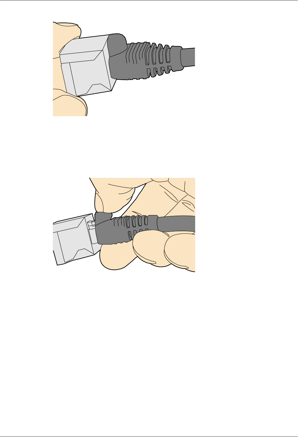
Figure 5-125 Installed shielded Ethernet connector
Step 4 To remove an Ethernet connector, press the locking key and pull out the connector, as shown
in Figure 5-126.
Figure 5-126 Removing a shielded Ethernet connector
----End
5.1.5.3.2 Installing an Unshielded Ethernet Connector
Procedure
Step 1 Hold the male and female connectors, with the male connector facing the female connector, as
shown in Figure 5-127.
AP4050DN-E
Hardware Installation and Maintenance Guide 5 Appendix
Issue 05 (2018-02-02) Huawei Proprietary and Confidential
Copyright © Huawei Technologies Co., Ltd.
104
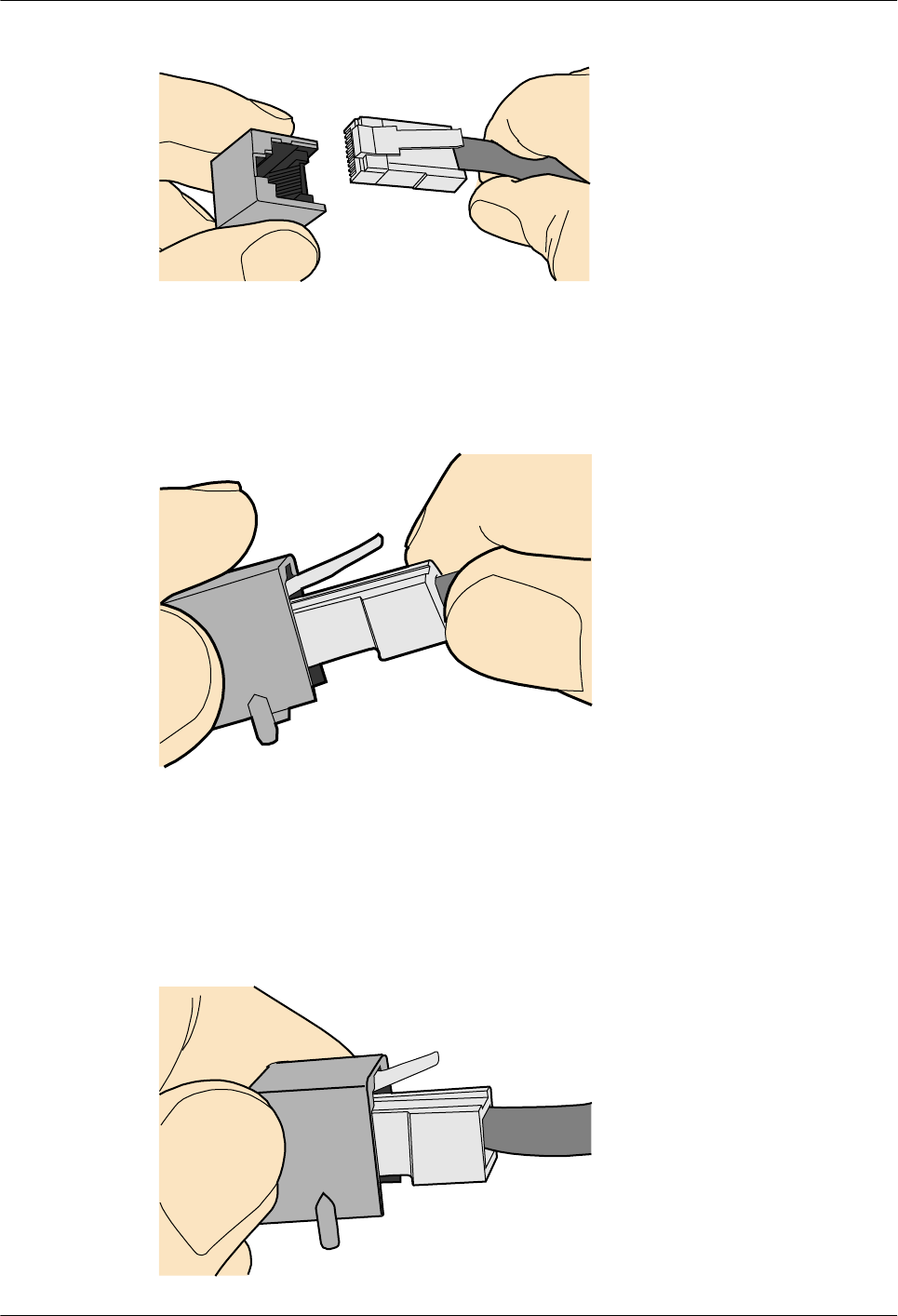
Figure 5-127 Holding the male and female unshielded connectors
Step 2 Feed the male connector into the female connector, as shown in Figure 5-128.
Figure 5-128 Feeding the male connector into the female unshielded connector
Step 3 A crisp click indicates that the connector is locked by the locking key. Pull the connector
slightly and ensure that it is securely connected. Figure 5-129 shows an installed Ethernet
connector.
Figure 5-129 Installed unshielded Ethernet connector
AP4050DN-E
Hardware Installation and Maintenance Guide 5 Appendix
Issue 05 (2018-02-02) Huawei Proprietary and Confidential
Copyright © Huawei Technologies Co., Ltd.
105
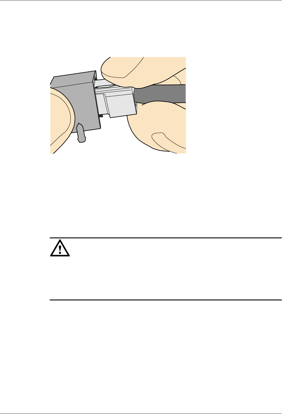
Step 4 To remove an Ethernet connector, press the locking key and pull out the connector, as shown
in Figure 5-130.
Figure 5-130 Removing an unshielded Ethernet connector
----End
5.1.5.4 Installing Fiber Connectors
Context
NOTICE
lAfter you remove the dustproof cap, ensure that the fiber pins are clean and install them as
soon as possible.
lWhen you disassemble fiber connectors, you must use a dedicated tool if the connectors
are densely installed.
5.1.5.4.1 Cleaning Fiber Connectors
Procedure
Step 1 Clean the pins of a fiber connector by using lint-free cotton and alcohol.
Step 2 Clean the pins again by using dust-free cotton. If necessary, clean the pins by using an air gun.
Ensure that the pins are free from any fiber or debris.
----End
5.1.5.4.2 Installing an FC Fiber Connector
AP4050DN-E
Hardware Installation and Maintenance Guide 5 Appendix
Issue 05 (2018-02-02) Huawei Proprietary and Confidential
Copyright © Huawei Technologies Co., Ltd.
106
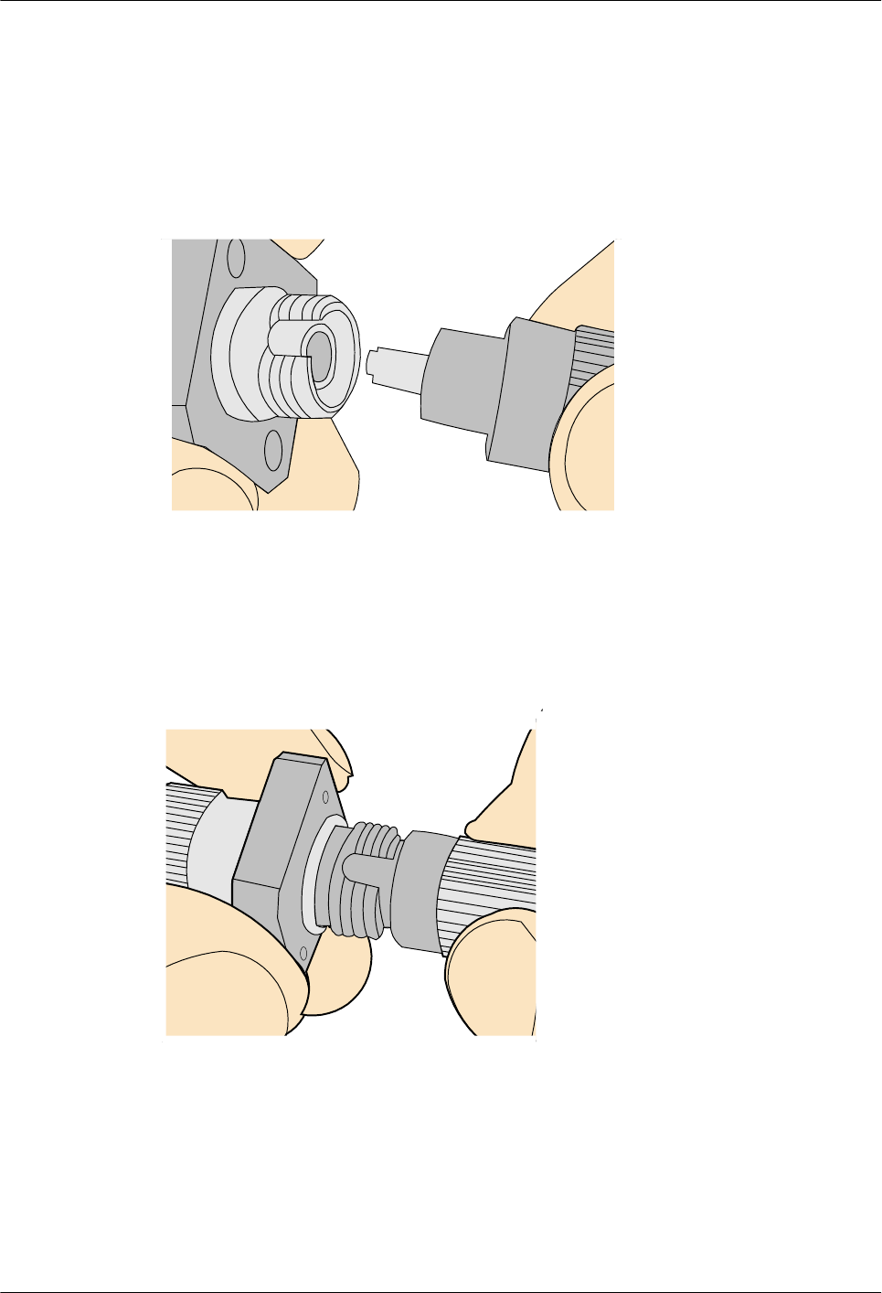
Procedure
Step 1 Remove the dustproof cap of the FC connector and store it for future use.
Step 2 Align the core pin of the male connector with that of the female connector, as shown in
Figure 5-131.
Figure 5-131 Aligning the male connector with the female connector
Step 3 Align the male connector with the female connector and gently push the male connector until
it is completely seated in the female connector, as shown in Figure 5-132.
Figure 5-132 Feeding the male connector into the female connector
Step 4 Fasten the locking nut clockwise and ensure that the connector is securely installed, as shown
in Figure 5-133.
AP4050DN-E
Hardware Installation and Maintenance Guide 5 Appendix
Issue 05 (2018-02-02) Huawei Proprietary and Confidential
Copyright © Huawei Technologies Co., Ltd.
107
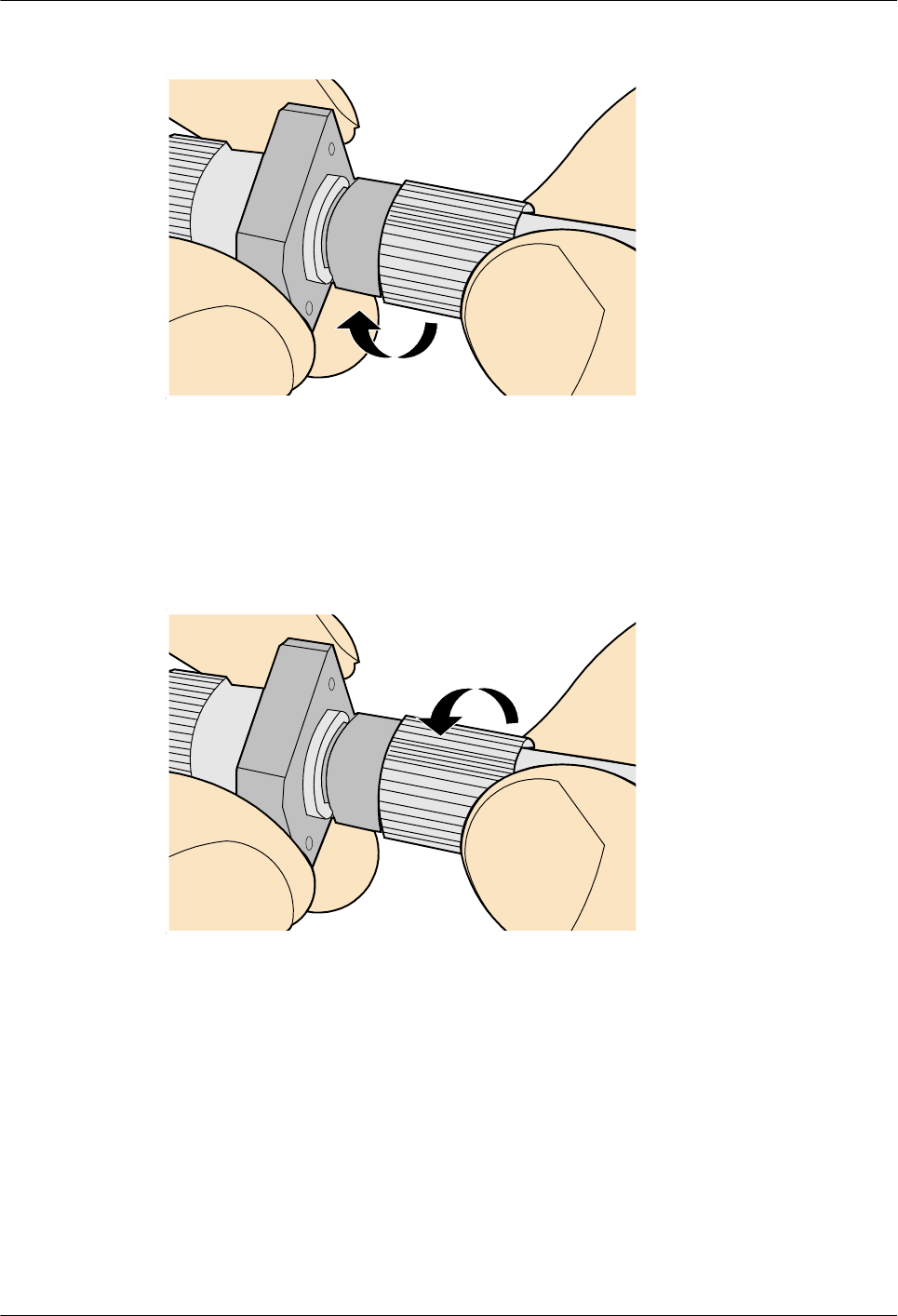
Figure 5-133 Fastening the locking nut
Step 5 To disassemble an FC fiber connector, loosen the locking nut counterclockwise, and gently
pull the male connector, as shown in Figure 5-134.
Figure 5-134 Disassembling an FC fiber connector
----End
5.1.5.4.3 Installing an LC Fiber Connector
Procedure
Step 1 Remove the dustproof cap of the LC fiber connector and store it for future use.
Step 2 Align the core pin of the male connector with that of the female connector, as shown in
Figure 5-135.
AP4050DN-E
Hardware Installation and Maintenance Guide 5 Appendix
Issue 05 (2018-02-02) Huawei Proprietary and Confidential
Copyright © Huawei Technologies Co., Ltd.
108
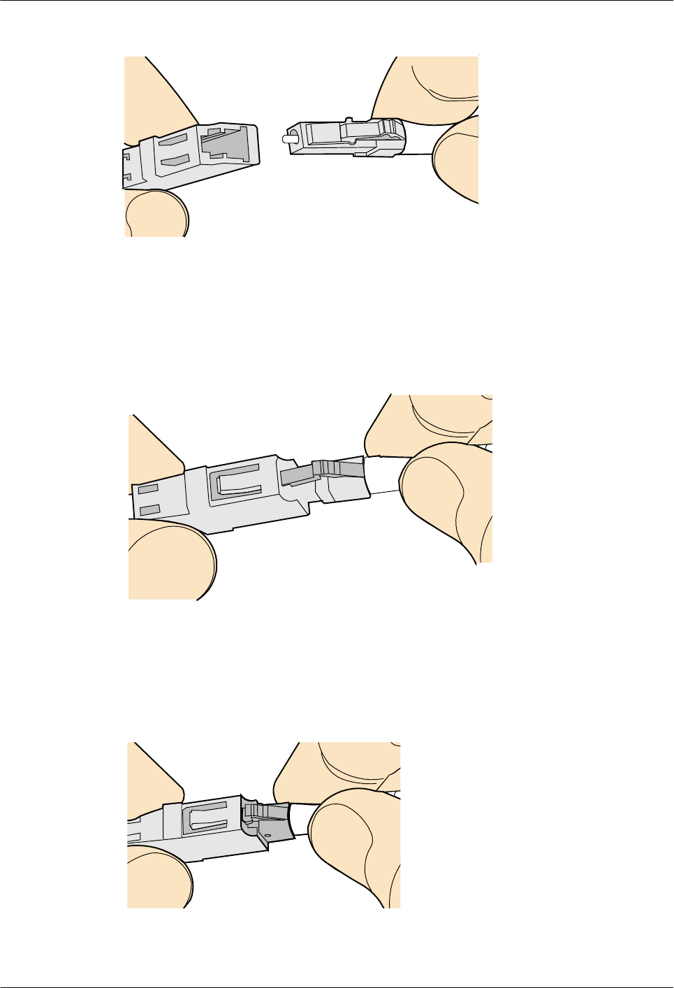
Figure 5-135 Aligning the male connector with the female connector
Step 3 Align the male connector with the fiber adapter and gently push the male connector until it is
completely seated in the fiber connector, as shown in Figure 5-136.
Figure 5-136 Feeding the male connector into the female connector
Step 4 A clicking sound indicates that the male connector is locked, as shown in Figure 5-137.
Figure 5-137 Installed LC connector
AP4050DN-E
Hardware Installation and Maintenance Guide 5 Appendix
Issue 05 (2018-02-02) Huawei Proprietary and Confidential
Copyright © Huawei Technologies Co., Ltd.
109
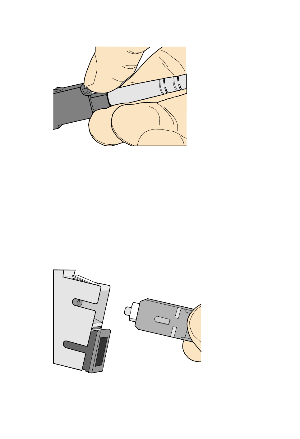
Step 5 To disassemble an LC fiber connector, press the locking nut to release the locking clips from
the bore, and gently pull the male connector, as shown in Figure 5-138.
Figure 5-138 Disassembling an LC fiber connector
----End
5.1.5.4.4 Installing the SC Fiber Connector
Procedure
Step 1 Remove the dustproof cap of the SC fiber connector and store it for future use.
Step 2 Align the core pin of the male connector with that of the female connector, as shown in
Figure 5-139.
Figure 5-139 Aligning the male connector with the female connector
Step 3 Feed the fiber connector into the female connector, with your fingers holding the shell of the
fiber connector (not the pigtail). When you hear a click, the fiber connector is secured by the
clips (internal parts, not illustrated in the figure). Pull the fiber connector gently. If the
connector does not loosen, the installation is complete. See Figure 5-140.
AP4050DN-E
Hardware Installation and Maintenance Guide 5 Appendix
Issue 05 (2018-02-02) Huawei Proprietary and Confidential
Copyright © Huawei Technologies Co., Ltd.
110
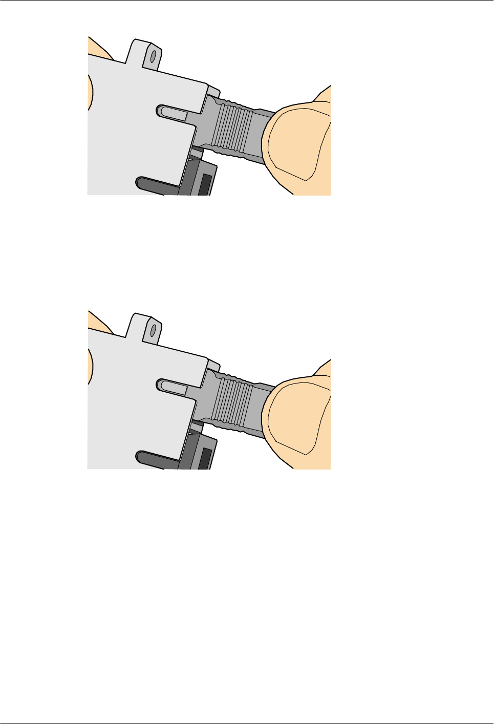
Figure 5-140 Installed SC fiber connector
Step 4 To disassemble an SC fiber connector, hold the shell of the connector (do not hold the fiber)
and gently pull the connector in the direction vertical to the adapter. Unlock the male
connector, and then separate it from the shell, as shown in Figure 5-141.
Figure 5-141 Disassembling an SC fiber connector
----End
5.1.5.4.5 Installing an MPO Connector
Procedure
Step 1 Remove the dustproof cap of the MPO fiber connector and store it for future use.
Step 2 Align the core pin of the male connector with that of the female connector, as shown in
Figure 5-142.
AP4050DN-E
Hardware Installation and Maintenance Guide 5 Appendix
Issue 05 (2018-02-02) Huawei Proprietary and Confidential
Copyright © Huawei Technologies Co., Ltd.
111
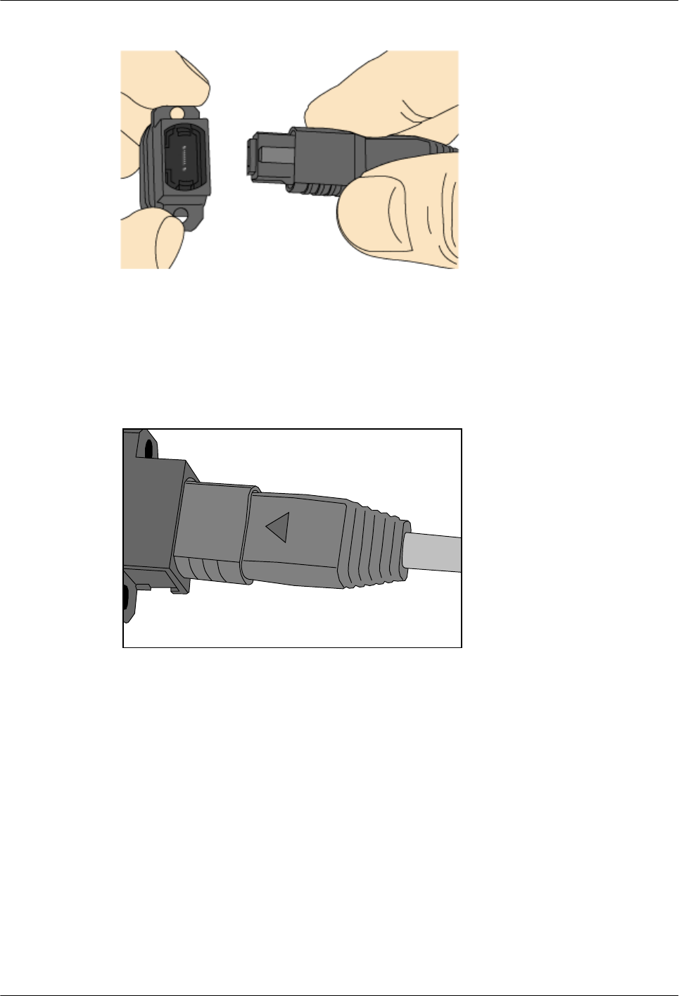
Figure 5-142 Aligning the male connector with the female connector
Step 3 Hold the shell labeled "PUSH" and feed the male connector into the female connector until
you hear a clicking sound. The male and female connectors are securely installed, as shown in
Figure 5-143.
Figure 5-143 Installed MPO fiber connector
Step 4 To disassemble an MPO fiber connector, hold the shell labeled "PULL" and remove the male
connector, as shown in Figure 5-144.
AP4050DN-E
Hardware Installation and Maintenance Guide 5 Appendix
Issue 05 (2018-02-02) Huawei Proprietary and Confidential
Copyright © Huawei Technologies Co., Ltd.
112
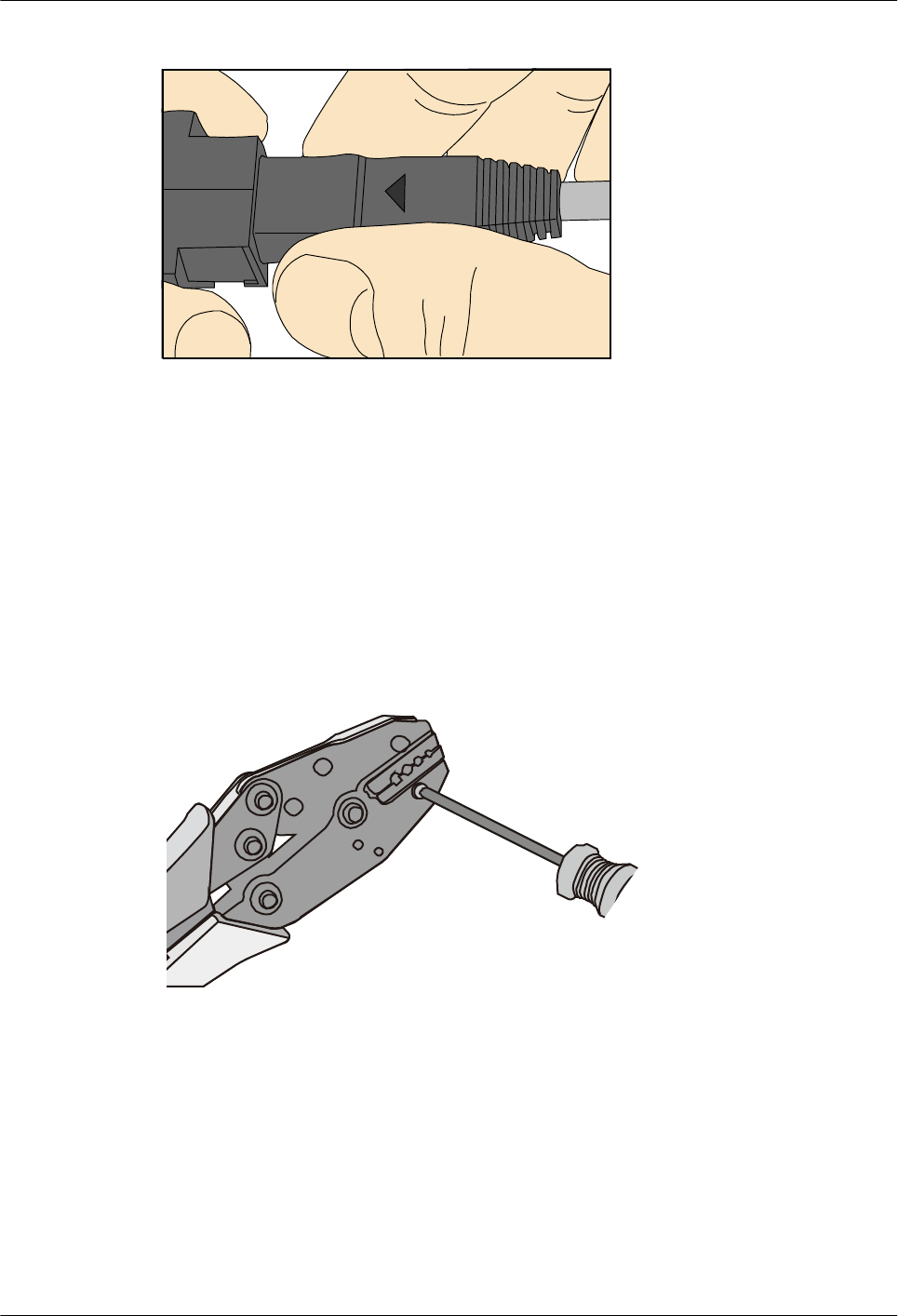
Figure 5-144 Disassembling an MPO fiber connector
----End
5.1.6 Replacing the Mold of the Crimping Tool
Procedure
Step 1 Hold the handles of a pair of COAX crimping tools. Loosen the two fastening screws
counterclockwise, as shown in Figure 5-145.
Figure 5-145 Loosening two fastening screws
Step 2 Hold the handles of the COAX crimping tools to open the self-locking mechanism. The jaw
of the COAX crimping tools opens automatically, as shown in Figure 5-146.
AP4050DN-E
Hardware Installation and Maintenance Guide 5 Appendix
Issue 05 (2018-02-02) Huawei Proprietary and Confidential
Copyright © Huawei Technologies Co., Ltd.
113
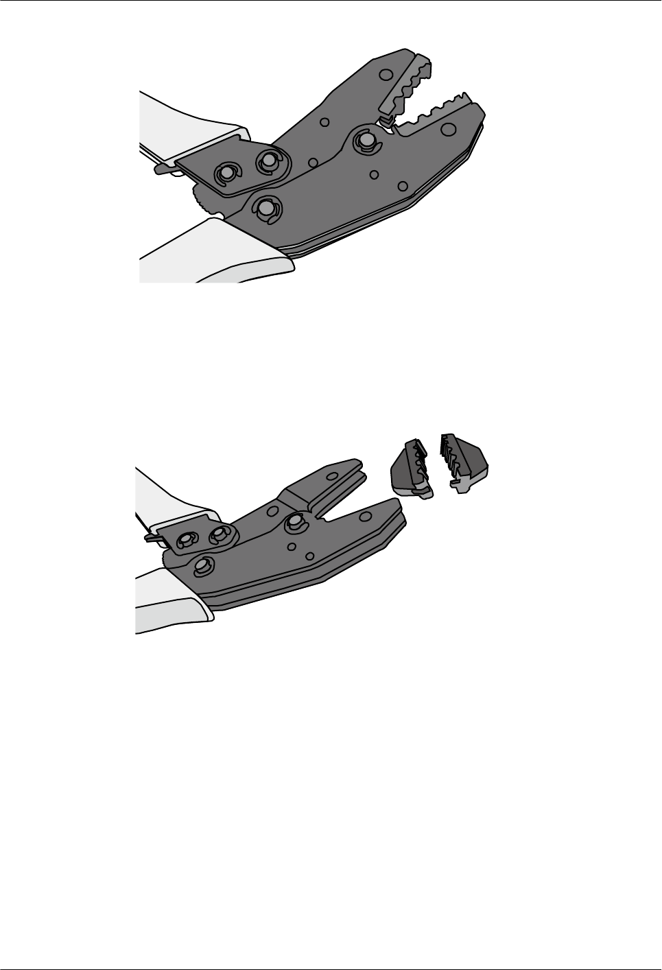
Figure 5-146 Pliers jaw opening automatically
Step 3 Remove the mold from the COAX crimping tools, as shown in Figure 5-147.
Figure 5-147 Removing the mold from the COAX crimping tools
Step 4 Place the mold to be installed into the jaw of the COAX crimping tools and align the screw
holes, as shown in Figure 5-148.
AP4050DN-E
Hardware Installation and Maintenance Guide 5 Appendix
Issue 05 (2018-02-02) Huawei Proprietary and Confidential
Copyright © Huawei Technologies Co., Ltd.
114
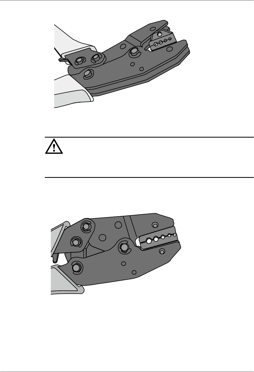
Figure 5-148 Installing a new mold in the COAX crimping tool
NOTICE
Keep the short side of the mold inwards and the long side outwards, with the teeth of the mold
aligning from the larger size to the smaller size.
Step 5 Hold the handles of the COAX crimping tools tightly to match the mold and the jaw
completely. Align the screw holes, as shown in Figure 5-149.
Figure 5-149 Aligning the screw holes
Step 6 Hold the handles of the COAX crimping tools with one hand. Tighten the two fastening
screws clockwise. Figure 5-150 and Figure 5-151shows the mold installed in the COAX
crimping tool.
AP4050DN-E
Hardware Installation and Maintenance Guide 5 Appendix
Issue 05 (2018-02-02) Huawei Proprietary and Confidential
Copyright © Huawei Technologies Co., Ltd.
115
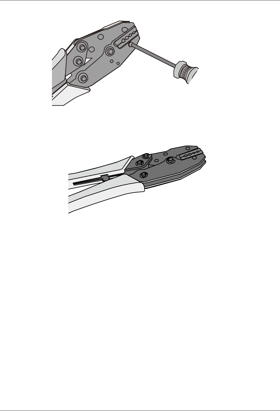
Figure 5-150 Mold installed in the COAX crimping tool
Figure 5-151 An installed mold
----End
5.2 Environmental Requirements for Device Operation
5.2.1 Environmental Requirements for an Equipment Room
5.2.1.1 Requirements for Selecting a Site for an Equipment Room
When designing a project, consider the communication network planning and technical
requirements of the equipment. Also consider hydrographic, geological, seismic, power
supply, and transportation factors.
Construction, structure, heating and ventilation, power supply, lighting and fire-proof
construction of the equipment room should be designed by specialized construction designers
to suit the environmental requirements of devices. The equipment room should also follow
local regulations concerning the industrial construction, environmental protection, fire safety,
and civil air defense. Construction must conform to government standards, regulations, and
other requirements.
AP4050DN-E
Hardware Installation and Maintenance Guide 5 Appendix
Issue 05 (2018-02-02) Huawei Proprietary and Confidential
Copyright © Huawei Technologies Co., Ltd.
116

The equipment room should be located in a place free from high temperature, dust, toxic
gases, explosive materials, or unstable voltage. Keep the equipment room away from
significant vibrations or loud noises, as well as power transformer stations.
The specific requirements for selecting a site for an equipment room are as follows:
lThe room should be located at a distance of at least 5 km (3.11 mi.) from heavy pollution
sources such as smelting and coal mines. It should be located at a distance of at least 3.7
km (2.30 mi.) from moderate pollution sources such as chemical, rubber, and
galvanization factories. It should be located at a distance of at least 2 km (1.24 mi.) from
light pollution sources such as packinghouses and tanyards. If these pollution sources
cannot be avoided, ensure that the equipment room is upwind of the pollution sources. In
addition, use a high-quality equipment room or protection products.
lThe room should be located away from livestock farms, or be upwind of the livestock
farms. Do not use an old livestock room or fertilizer warehouse as the equipment room.
lThe equipment room must be far away from residential areas. An equipment room that is
not far away from residential areas must comply with equipment room construction
standards to avoid noise pollution.
lThe room should be located far away from industrial and heating boilers.
lThe room should be at least 3.7 km (2.30 mi.) away from the seaside or salt lake.
Otherwise, the equipment room should be airtight with cooling facilities. In addition,
alkalized soil cannot be used as the construction material. Otherwise, equipment suitable
for wet conditions must be used.
lThe doors and windows of the equipment room must be kept closed to maintain an
airtight room.
lUsing steel doors to ensure sound insulation is recommended.
lNo cracks or openings are allowed on the walls or floors. The outlet holes on the walls or
windows must be sealed. Walls must be constructed such that they are smooth, wear-
resistant, dustproof, flame retardant, sound insulated, heat absorptive, and have
electromagnetic shielding.
lThe air vent of the room should be far from the exhaust of city waste pipes, big cesspools
and sewage treatment tanks. The room should be in the positive pressure state to prevent
corrosive gases from entering the equipment room and corroding components and circuit
boards.
lIt is recommended that the room be on or above the second floor. If this requirement
cannot be met, the ground for equipment installation in the room should be at least 600
mm (23.62 in,) above the maximum flood level.
lThe equipment room should be strong enough to resist winds and downpours.
lThe room should be located away from dusty roads or sand. If this is unavoidable, the
doors and windows of the equipment room must not face pollution sources.
lDo not place air conditioning vents near the equipment so that they blow directly on the
equipment because condensation may be blown into the equipment.
lDo not use decorative materials that contain sulfur in the equipment room.
5.2.1.2 Equipment Room Layout
An equipment room usually contains mobile switching equipment, telecommunications
equipment, power supply equipment, and other auxiliary equipment. To ensure easy
maintenance and management, place the equipment in different rooms. Figure 5-152 shows
the layout of the equipment room.
AP4050DN-E
Hardware Installation and Maintenance Guide 5 Appendix
Issue 05 (2018-02-02) Huawei Proprietary and Confidential
Copyright © Huawei Technologies Co., Ltd.
117
Figure 5-152 Layout of the equipment room
Control room Generator room
Transmission
room
Main communication
equipment room
Power distribution
room Battery room
Substation room
Communication cable and optical cable
Power cable
The general layout principles of the equipment room are as follows:
lIt should meet requirements for laying out and maintaining communication cables and
power cables.
lIt should reduce the cabling distance, which facilitates cable maintenance, reduces
potential communication faults, and maximizes efficiency.
5.2.1.3 Construction Requirements for the Equipment Room
Table 5-15 describes the construction requirements for the equipment room.
Table 5-15 Construction requirements for the equipment room
Item Requirements
Area The smallest area of the equipment room can accommodate the
equipment with the largest capacity.
Net height The minimum height of the equipment room should not be less than 3 m
(9.84 ft). The minimum height of the equipment room is the net height
below overhead beams or ventilation pipes.
Floor The floor in the equipment room should be semi-conductive and
dustproof. A raised floor with an ESD covering is recommended. Cover
the raised floor tightly and solidly. The horizontal tolerance of each
square meter should be less than 2 mm (0.08 in.). If raised floors are
unavailable, use a static-electricity-conductive floor material, with a
volume resistivity of 1.0 x 10⁷ ohms to 1.0 x 10¹⁰ ohms. Ground this
floor material or raised floor. You can connect them to ground using a
one megohm current-limiting resistor and connection line.
Load-bearing
capacity
The floor must bear loads larger than 150 kg/m2 (0.21 bf/in.2).
AP4050DN-E
Hardware Installation and Maintenance Guide 5 Appendix
Issue 05 (2018-02-02) Huawei Proprietary and Confidential
Copyright © Huawei Technologies Co., Ltd.
118
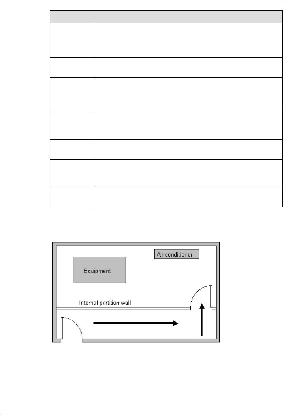
Item Requirements
Door and
windows
The door of the equipment room should be 2 m (6.56 ft) high and 1 m
(3.28 ft) wide. One door is enough. Seal the doors and windows with
dustproof plastic tape. Use double-pane glass in the windows and seal
them tightly.
Wall surface
treatment
Paste wallpaper on the wall or apply flat paint. Do not use pulverized
paint.
Cable trays Use cable trays to arrange cables. The inner faces of the cable trays must
be smooth. The reserved length and width of the cable trays, and the
number, position and dimensions of the holes must comply with the
requirements of device arrangement.
Water pipe Do not pass service pipes, drainpipes, and storm sewers through the
equipment room. Do not place a fire hydrant in the equipment room, but
place it in the corridor or near the staircase.
Internal
partition wall
Separate the area where the equipment is installed from the equipment
room door. The partition wall can block some outside dust.
Installation
position of the
air conditioner
Install air conditioner vents so that the air does not blow directly on
equipment.
Other
requirements
Avoid the proliferation of mildew, and keep out rodents (like mice).
Figure 5-153 Internal partition wall inside the equipment room
5.2.1.4 Equipment Room Environment
Dust on devices may cause electrostatic discharge and result in poor contact for connectors or
metal connection points. This problem can shorten the life span of devices and cause faults.
AP4050DN-E
Hardware Installation and Maintenance Guide 5 Appendix
Issue 05 (2018-02-02) Huawei Proprietary and Confidential
Copyright © Huawei Technologies Co., Ltd.
119
The equipment room must be free from explosive, conductive, magnetically-permeable, and
corrosive dust. Table 5-16 lists the requirement for dust concentration in the equipment room.
Table 5-16 Requirements for dust particles in the equipment room
Mechanical active
material
Unit Concentration
Dust particle Particle /m3≤ 3x 10⁴
(no visible dust accumulated
on a workbench in three
days)
Suspending dust mg/m3≤0.2
Precipitable dust mg/m2·h ≤1.5
Description
lDust particle diameter ≥ 5 µm
lSuspending dust diameter ≤ 75 µm
l75 µm ≤ precipitable dust diameter ≤ 150 µm
Take the following measures to meet the requirements:
lUse dustproof materials for ground, wall, and ceiling construction.
lUse screens on the door and windows facing outside. The outer windows should be dust-
proof.
lClean the equipment room regularly and clean the air filter monthly.
lWear shoe covers and ESD clothing before entering the equipment room.
5.2.1.5 Requirements for Corrosive Gases
The room should be free from dusts and corrosive gases, such as SO2, H2S, and NH3. Table
5-17 lists the requirements for the corrosive gas concentration.
Table 5-17 Requirements for corrosive gas concentration
Chemical active
material Unit Concentration
SO2mg/m3≤0.30
H2Smg/m3≤0.10
NOxmg/m3≤0.50
NH3mg/m3≤1.00
Cl2mg/m3≤0.10
HCl mg/m3≤0.10
AP4050DN-E
Hardware Installation and Maintenance Guide 5 Appendix
Issue 05 (2018-02-02) Huawei Proprietary and Confidential
Copyright © Huawei Technologies Co., Ltd.
120

Chemical active
material Unit Concentration
HF mg/m3≤0.01
O3mg/m3≤0.05
Take the following measures to meet the requirements:
lAvoid constructing the room near a place where the corrosive gas concentration is high,
such as a chemical plant.
lEnsure the air intake vent of the room is in the prevailing upwind direction from any
pollution source.
lPlace batteries in different rooms.
lA professional service should monitor the corrosive gas conditions regularly.
5.2.1.6 Requirements for ESD Prevention
The absolute value of electrostatic voltage must be less than 1000 V.
Take the following measures to meet this requirement:
lTrain operators about ESD prevention.
lKeep the correct humidity level in the equipment room to reduce the impact of static
electricity.
lLay out an ESD floor in equipment rooms.
lWear ESD shoes and clothing before entering equipment room.
lUse ESD tools, such as wrist straps, tweezers, and pullers.
lGround all conductive materials in the room, including computer terminals. Use ESD
worktables.
lKeep non-ESD materials (such as common bags, foam, and rubber) at least 30 cm (11.81
in.) away from boards and ESD-sensitive components.
5.2.1.7 Electromagnetism Requirements for the Equipment Room
All interference sources, inside or outside the equipment room, can cause equipment problems
with capacitive coupling, inductive coupling, electromagnetic wave radiation, and common
impedance (including grounding system) coupling. Prevent the interference using these
approaches:
lTake effective measures against electrical interference from the power supply system.
lDo not use the working ground of the equipment as the same ground for surge
protection. Separate them as far as possible.
lKeep the equipment far away from high-power radio transmitters, radar units, and high-
frequency and high-current equipment.
lUse electromagnetic shielding if necessary.
5.2.1.8 Requirements for Lightning Proof Grounding
Table 5-18 lists the requirements for lightning proof grounding.
AP4050DN-E
Hardware Installation and Maintenance Guide 5 Appendix
Issue 05 (2018-02-02) Huawei Proprietary and Confidential
Copyright © Huawei Technologies Co., Ltd.
121

Table 5-18 Requirements for lightning proof grounding
Item Requirements
Capital
construction
lUse reinforced concrete to construct the equipment room.
lInstall a lightning proof device like a lightning rod outside the room.
lThe lightning proof ground shares the same grounding body with
the protective ground of the room.
Power cables
leading in the
equipment room
need to be
equipped with a
surge protector
lAfter the low-voltage power cables are led into the room, install the
surge protector for the power cables in the AC voltage stabilizer and
the AC power distribution panel (box). Correctly ground the surge
protector nearby.
lFor an equipment room in urban area, install a power supply surge
protector with the nominal discharge current of no less than 20 kA.
For an equipment room that is built in a suburb and subject to
lightning strikes, install a power supply surge protector with the
nominal discharge current of more than 60 kA. For an equipment
room that is built in a mountain area and subject to frequent
lightning strikes, or in a separate high-rise building in a city, install a
power supply surge protector with the nominal discharge current of
more than 100 kA.
lThe ground cable of the surge protector should be no longer than 1
m (3.28 ft).
Grounding for
DC power
distribution
lConnect the DC working ground (positive pole of the -48 V DC
power supply or the negative pole of the 24 V DC power supply)
with the indoor collective ground cable nearby. The total ground
cable should meet the maximum load of the equipment.
lThe power equipment must have a DC working ground cable, which
can connect the power equipment to the collective ground cable of
the telecommunication site (or the protective ground bar of the
equipment room).
Equipotential
connection
lProperly ground the devices and auxiliary devices in the room such
as mobile base station, transmission, switching equipment, power
supply equipment, and cable distribution frame. Connect all PGND
cables to the collective protective ground bar. Connect all PGND
cables in one equipment room to one protective ground bar.
lApply joint grounding to the working ground and protective ground
of devices, which means the two share one grounding network.
lThe cable tray, rack or shell, metal ventilation pipe, metal door or
window of the equipment should be grounded for protection.
General
requirements for
grounding
lDo not connect the neutral line of the AC power cable with the
protective ground of any telecom equipment in the equipment room.
lDo not install a fuse or switch on the ground cable.
lAll ground cables should be as short as possible, and arranged in a
straight line.
AP4050DN-E
Hardware Installation and Maintenance Guide 5 Appendix
Issue 05 (2018-02-02) Huawei Proprietary and Confidential
Copyright © Huawei Technologies Co., Ltd.
122

Item Requirements
Grounding
resistance
lThe grounding resistance must be lower than 1 ohm.
lThe upper end of the grounding body should be at least 0.7 m (2.30
ft) over the ground. In cold areas, bury the grounding body below
the frozen ground.
lMeasure the grounding resistance periodically to ensure effective
grounding.
Routing of
signal cable
lDo not arrange the signal cables overhead in the equipment room.
All signal cables must be led into the site underground.
lUse the cables with a metal jacket or place them into a metal pipe if
they come out/in the equipment room.
lGround the idle lines inside the cable in the equipment room.
lSignal cables should be deployed on internal walls. Do not deploy
outdoor aerial cables.
lKeep signal cables away from power cables and surge protection
devices.
Collective
ground cable
lUse a ground ring or ground bar for the collective ground cable.
lDo not use aluminum cables as ground cables. Adopt measures to
prevent electrification corrosion when connecting different metal
parts together.
lUse a copper busbar as the collective ground cable with a cross-
sectional area of no less than 120 mm2 (0.19 in.2), or use the
galvanized flat steel of the same resistance. Insulate the collective
ground cable from the reinforcing steel bars of the building.
Grounding lead-
in
The grounding lead-in should be a maximum of 30 m (98.42 ft) long.
Use the galvanized flat steel with cross-sectional area of 40 mm x 4
mm (1.58 in. x 0.158 in.) or 50 mm x 5 mm (1.97 in. x 0.197 in.).
5.2.2 Requirements for Power Supply
5.2.2.1 Requirements for AC Power Supply
An AC power supply system consists of power mains, uninterruptible power supplies (UPSs),
and self-supplied electric generators. In addition to meeting the requirements of the server
load, the AC power supply must have a simple connection line, safe operation, flexible
scheduling, and easy maintenance.
The low-voltage power supply should be 3-phase, 5-wire mode or monophase 3-wire mode.
This AC power supply should be 110 V/220 V, with a frequency of 50 Hz.
The UPS should supply the same power and operate at the same phase as the power mains.
The switching time between the UPS and mains should be less than 10 ms; otherwise, the
networking devices will reboot or reset.
For power distribution capacity in the equipment room, both the working current and fault
current of the devices should be considered. Ensure that independent AC power supplies
AP4050DN-E
Hardware Installation and Maintenance Guide 5 Appendix
Issue 05 (2018-02-02) Huawei Proprietary and Confidential
Copyright © Huawei Technologies Co., Ltd.
123
protect independent devices. Configure the current-carrying capacity of the protection switch
of the equipment room for more than that of the devices.
Table 5-19 lists the voltage range of the AC power supply for the devices.
Table 5-19 Voltage range of AC power supply
Item Requirements
AC power capacity to
support the devices
-10% to +5% of the rated voltage
AC power capacity to
support the power modules
and important buildings
-15% to +10% of the rated voltage
Frequency of alternating
current
-4% to +4% of the rated value
Voltage wave shape sine
distortion
Within 5% of the rated voltage
The automated electric generator must have a standard interface that supports
telecommunication protocols, remote telecommunication, monitoring, and control.
AC power cables should meet the following specifications:
lAC neutral should have a conductor with the same cross section as the phase line.
lAC cables should have non-flammable insulation. The layout of AC cables should
comply with local regulations. Low-voltage power distribution rooms should comply
with local regulations.
5.2.2.2 Recommendations for AC Power Supply
The following are recommendations for the AC power supply.
lIf the voltage of the power mains that supply power directly to devices exceeds the rated
voltage by -10% to 5%, or exceeds the voltage range that devices can support, a voltage
regulating device or voltage stabilizing device is required.
lIf the mains do not supply power for the device directly, or if the mains voltage exceeds
the rated voltage by -15% to 10% or exceeds the input voltage range of the DC power
supply, a voltage regulating device or voltage stabilizing device is required.
lA UPS or inverter power supply system is required to provide uninterrupted AC power
to support the telecommunication load.
lIf abnormalities occur on the mains, telecommunication servers should be equipped with
a self-supplied electric generator to support the key telecommunication load. The
capacity should be not less than 150% to 200% of the total uninterruptible power supply.
lStorage batteries are usually installed in a parallel connection of two groups. UPS
storage batteries are generally installed in one group. The redundancy required for the
UPS can rely on concatenation or parallel connection. When an inverter or a UPS is
used, the active inverter is determined by the maximum power and a backup inverter is
required.
AP4050DN-E
Hardware Installation and Maintenance Guide 5 Appendix
Issue 05 (2018-02-02) Huawei Proprietary and Confidential
Copyright © Huawei Technologies Co., Ltd.
124
5.2.2.3 Requirements for DC Power Supply
The equipment room should receive stable and reliable DC power. Deploy the power
equipment near the telecommunications equipment to make the DC feeder as short as
possible. To reduce power consumption and installation cost, the loop voltage drop from the
battery port to the equipment port should be less than 3.2 V.
lA large-scale enterprise can deploy an independent power supply system on each floor to
supply power to the telecommunications equipment room on the respective floor.
lA medium-scale enterprise can use a power room and a battery room for centralized
power supply or use distributed power supply systems.
lA small-scale enterprise can deploy an integrated power supply system in its equipment
room but must take measures to prevent corrosive gases released from batteries from
eroding circuit boards of telecommunications equipment.
Table 5-20 lists the specifications for the DC power supply.
Table 5-20 Specifications for the DC power supply
Item Requirements
DC power
capacity to
support the surge
current
Greater than 1.5 times the rated current
Regulated
voltage precision
If the AC input voltage is in the range of 85% to 110% of the rated
value, and the load current is in the range of 5% to 100% of the rated
value, the output voltage of the rectifier ranges from -46.0 V to -56.4 V,
with the regulated voltage precision less than or equal to 1%.
Overshoot
amplitude of
switch on/off
Integral value of the DC output voltage ±5%
Peak noise
voltage
≤200 mV
Dynamic
response
The recovery time is less than 200 ms. The overshoot is in the range of
the integral value of the DC output voltage ±5%.
5.2.2.4 Recommendations for DC Power Supply
The following are recommendations for the DC power supply.
lUse distributed power supply mode. Use multiple DC power supply systems and put
power equipment in multiple locations.
lAdopt a standard DC power supply system, and set the output voltage to the
communications equipment within the required range.
lImprove reliability of the AC power supply system to reduce the necessary capacity of
storage batteries. For small offices, increase the capacity of storage batteries if it is
difficult to enhance reliability of the AC power supply system.
AP4050DN-E
Hardware Installation and Maintenance Guide 5 Appendix
Issue 05 (2018-02-02) Huawei Proprietary and Confidential
Copyright © Huawei Technologies Co., Ltd.
125
lThe total capacity of the high-frequency switching rectifier must satisfy the power of the
communication loading and battery charging. If there are 10 or fewer active rectifier
modules, configure one backup module. If there are more than 10 active modules,
configure one backup module for every 10 active modules.
lInstall storage batteries in two or more groups. The capacity is determined by the
duration for which the storage batteries must supply power. For most offices, the
batteries should be able to supply power for at least one hour.
5.3 Equipment Grounding Specifications
5.3.1 General Grounding Specifications
Table 5-21 shows the general grounding specifications.
Table 5-21 General grounding specifications
No. Description
1 The working ground and protective ground, including the shielded ground and the
lightning-proof ground of the cable distribution frame should share the same
grounding conductor.
2 The cable trays, shells, metal ventilation pipes, metal doors and windows in the
equipment room should be grounded for protection.
3 The metal parts of the equipment which are electrically floating in normal
conditions should be grounded for protection.
4 The ground cable must be connected securely to the protective ground bar of the
equipment room.
5 Do not use other equipment as part of the ground cable or electrical connection.
5.3.2 Grounding Specifications for an Equipment Room
The grounding resistance of a comprehensive communication building should be less than or
equal to one ohm. The grounding resistance of an ordinary communication office should be
less than five ohms. The grounding resistance in an area where the earth resistance rate is high
should be less than 10 ohms.
5.3.3 Grounding Specifications for Devices
Table 5-22 lists the equipment grounding specifications.
AP4050DN-E
Hardware Installation and Maintenance Guide 5 Appendix
Issue 05 (2018-02-02) Huawei Proprietary and Confidential
Copyright © Huawei Technologies Co., Ltd.
126
Table 5-22 Equipment Grounding Specifications
No. Description
1 All communication devices and auxiliary devices (such as mobile base stations,
transmission and switching devices, power supply devices) in the equipment room
should be grounded for protection. Connect all protective ground for various
devices jointly to a general ground bar, and then to the same protective ground bar
in the room together with the protective ground (PGND) of the device.
2 The PGND of the equipment is shorted to the copper ground bar provided by the
customer. The short-circuiting cable used should be a yellow-green plastic
insulated cable with a copper core and a cross-sectional area greater than 25 sq.
mm (0.039 sq. in.).
3 There are grounding terminals and grounding lugs at the lower part of the front
door, rear door and side panel of the cabinet, connected to the grounding terminals
of the cabinet framework through connection cables with cross-sectional area of no
less than 1.6 sq. mm (0.002 sq. in.).
4 Ensure that all metal components of the cabinet conduct well. No insulating
coating should be sprayed on the connection part of the metal components.
5 Connect the cabinets in the same row by fastening captive screws and gaskets on
the top of the cabinets. Do not spray any coating into a rectangular area measuring
30 mm x 50 mm (1.18 in. x 1.97 in.) around the connection hole for a captive bolt.
Measures to prevent rust and corrosion must be taken for this area. Zinc
electroplating with iridescent yellow chromate conversion coating should be
applied to the gasket and nut to ensure good electrical contact.
6 When combining cabinets of the same type, short-circuiting cables are required to
connect the ground busbars (if any) of the cabinets. The cross-sectional area of the
short-circuiting cable is 6 sq. mm (0.009 sq. in.) and is no more than 300 mm (11.8
in.) long. Connect the two ends of the short-circuiting cable to the ground busbar
terminals of neighboring cabinets and fix them firmly.
5.3.4 Grounding Specifications for Communications Power
Supply
Table 5-23 shows the grounding specifications for communication power supplies.
Table 5-23 Grounding specifications for communication power supplies
No. Description
1 The inlet for the AC power cable at the equipment room should be equipped with a
surge protection device (C-level) with a nominal discharge current no less than 20
kA.
2 The protective ground for the power supply and that for communication equipment
share the same grounding conductor. If the power supply and the equipment are in
the same equipment room, use the same protective ground bar for them if possible.
AP4050DN-E
Hardware Installation and Maintenance Guide 5 Appendix
Issue 05 (2018-02-02) Huawei Proprietary and Confidential
Copyright © Huawei Technologies Co., Ltd.
127
No. Description
3 Use a surge protection circuit on the AC power interface.
4 The positive of the -48 V DC power supply or negative pole of the 24 V DC power
supply should be grounded at the output of the DC power supply.
5 The working ground and protective ground of the DC power supply equipment
should use the same grounding conductor with the protective ground of the
switching equipment. If the power supply and equipment are in the same
equipment room, use the same protection ground bar for them if possible.
6 Add surge protection on the DC power interface.
5.3.5 Grounding Specifications for Signal Cables
Table 5-24 lists the grounding specifications for signal cables.
Table 5-24 Grounding specifications for signal cables
No. Description
1 Equip the cable outdoors with a metal jacket, well grounded at both ends, or
connect the ends of the metal jacket to the protective ground bar of the equipment
room. For cables inside the equipment room, install surge protection devices at the
interface to the equipment. The PGND cable for the surge protection devices
should be as short as possible.
2 The incoming and outgoing signal cables to and from the office and unused wires
inside the cable should be grounded for protection.
3 The Tone & Data Access (TDA) cable must pass through the Main Distribution
Frame (MDF) with surge protective device (SPD) when going out of the office.
The cable's shield layer should be connected to the protective ground of the MDF.
The MDF should use the same grounding conductor as the cabinet.
4 Do not route signal cables overhead.
5.3.6 Specifications for Laying Out Grounding Cables
Table 5-25 shows the specifications for the ground cable.
Table 5-25 Specifications for laying out ground cables
No. Description
1 The grounding wire should not run parallel to or twist around the signal cable.
AP4050DN-E
Hardware Installation and Maintenance Guide 5 Appendix
Issue 05 (2018-02-02) Huawei Proprietary and Confidential
Copyright © Huawei Technologies Co., Ltd.
128

No. Description
2 Bury ground underground or arrange them indoors. Do not route ground cables
overhead.
3 Do not connect two cables together to extend the PGND cable, or add any switches
or fuses.
4 The PGND cable should be an alternating yellow and green plastic insulated one
with a copper core.
5 The neutral line of the AC power cable cannot be connected to the protective
ground of transmission and communication equipment in the equipment room.
6 A PGND cable should be as short as possible, with a length of no more than 45 m
(147.64 ft).
5.4 Engineering Labels for Cables
An engineering label serves as an identifier for on-site installation and maintenance after the
installation. Labels on the cables facilitate correct and orderly connection of cables, and easy
maintenance after installation.
Engineering labels are specialized for power cables and signal cables:
lSignal cables include network cables, optical fibers, and user cables.
lPower cables include the AC power cables and DC power cables.
NOTE
Fill in labels according to specified requirements to keep consistency of labels in the equipment room.
Make a relevant statement in the self-check report.
5.4.1 Introduction to Labels
5.4.1.1 Label Materials
Features:
lThickness: 0.09 mm (0.004 in.)
lColor: chalk white
lMaterial: polyester (PET)
lAmbient temperature: -29°C (-20.2°F) to +149°C (300.2°F)
lPrinted by a laser printer and written with a marker
lPass UL and CSA authentication
AP4050DN-E
Hardware Installation and Maintenance Guide 5 Appendix
Issue 05 (2018-02-02) Huawei Proprietary and Confidential
Copyright © Huawei Technologies Co., Ltd.
129
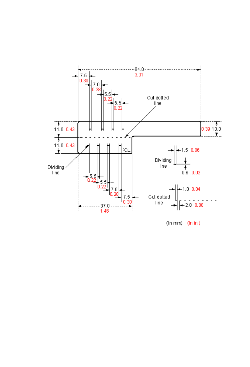
5.4.1.2 Type and Structure
Label for Signal Cables
The label for signal cables is L-shaped with fixed dimensions, as shown in Figure 5-154.
Figure 5-154 Label for signal cables
To specify more clearly the position of a cable, use the dividing lines on the label. For
example, there is a dividing line between the cabinet number and the chassis number, and
another one between the chassis number and the slot number. Each dividing line is light blue
(Pantone 656c) and 1.5 mm x 0.6 mm (0.06 in. x 0.02 in.).
The cut dotted line helps to fold the label when affixed to the cable, and its size is 1 mm x 2
mm (0.04 in. x 0.08 in.).
The word "TO:" (upside down in the figure) at the lower right corner of the label is used to
identify the opposite end of the cable on which the label is affixed.
Power Cable Label
The label for power cables should be attached to the identification plate on the cable ties that
are attached to the cable. The identification plate has an embossed area 0.2 mm x 0.6 mm
(0.008 in. x 0.02 in.) around (symmetric on both sides), and the area in the middle is for
affixing the label, as shown in Figure 5-155.
AP4050DN-E
Hardware Installation and Maintenance Guide 5 Appendix
Issue 05 (2018-02-02) Huawei Proprietary and Confidential
Copyright © Huawei Technologies Co., Ltd.
130
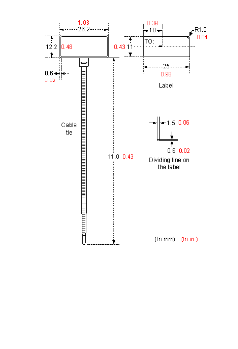
Figure 5-155 Power cable label
5.4.1.3 Label Printing
The contents can be printed or written on the labels. Printing is recommended for the sake of
high efficiency and eye-pleasant layout.
Template for Printing
You can obtain a template from the Huawei local office to print labels.
The template is made in Microsoft Word. Follow these instructions to use the template:
lYou can modify the contents of the template. Do not change settings of centered
characters, direction, and fonts.
AP4050DN-E
Hardware Installation and Maintenance Guide 5 Appendix
Issue 05 (2018-02-02) Huawei Proprietary and Confidential
Copyright © Huawei Technologies Co., Ltd.
131
lIf many characters need to be filled in, decrease the font size, but make sure that the
printouts are clear and legible.
Merging Cells in the Template
To merge two or more cells, do as follows:
1. Select Edit/Select All.
2. Select Format/Borders and Shading/Borders. Select Box tab and click OK.
3. Drag the mouse to select cells to be merged and select the Table/Merge Cells.
Requirements on the Printer
To print labels, use a laser jet printer of any model. Before printing labels, set up the page and
try printing.
1. Try printing on ordinary paper with both sides blank. Place the blank paper over the
whole page of the label paper, and check whether the page setup conforms to the label
layout.
2. Make sure the printer properties, such as "paper size" and "direction", have been set
correctly.
–If the printout conforms to the sheet of labels, print the labels on the label paper.
–If the printout does not conform, adjust the page setup and try printing again until
the correct printout is produced.
The method for adjusting the page setup is as follows.
1. Select File/Page Setup.
2. Select Layout and set Header and Footer as 0.
3. Select the Margins tab page. Select Left for Gutter Position and adjust the values of Top,
Bottom, Left, and Right.
NOTE
If the warning prompt as shown in Figure 5-156 appears before printing, click Ignore to continue
the printing.
Figure 5-156 Warning prompt before printing
After the page setup has been made correctly, save it for future use. This page setup is only
necessary the first time you use the template to print the labels.
AP4050DN-E
Hardware Installation and Maintenance Guide 5 Appendix
Issue 05 (2018-02-02) Huawei Proprietary and Confidential
Copyright © Huawei Technologies Co., Ltd.
132

Requirements for Feeding the Printer
The label paper consists of two layers and has undergone multiple processing procedures such
as printing and cutting. No matter what model of printer you use, feed in the labels one page
at a time. To avoid jamming the labels, never use the auto-feed mode.
Feed in the label paper in the correct direction to ensure that the text is printed in a correct
position.
Requirements for the Printed Label
Make sure that the printed labels satisfy the following requirements:
lAll the printouts must be on the label, and nothing should be printed on the backing layer
of the label page.
lContents in the cells should be aligned in the center. In a single-line printout, the
dividing lines and the word "TO:" should not be covered by printed characters.
lWhen the cells are merged and the printouts are made in multiple lines, avoid covering
the word "TO:" when printing the text. Use the space bar to move the text to the next
line.
5.4.1.4 Writing Labels
Writing Tools
To make sure the printouts are clear and legible, use black markers instead of ball-point pens
to write the labels.
If no marker is available, black ball-point pens are allowed, although not recommended.
Compared with ball-point pens, waterproof markers are better. When writing with a ball-point
pen, do not leave the oil on the label, which may contaminate the label and blur the words.
NOTE
The delivered marker has two nibs. Use the smaller nib to write the labels.
Font
For the sake of legibility, use standard block letters and numbers as shown in Table 5-26
(Times New Roman).
Table 5-26 Standard typeface for handwriting
012345678
9 A B C D E F G H
I J K L M N O P Q
R S T U V W X Y Z
Determine the size of characters based on the number of letters or digits and ensure that the
characters are distinct and tidy.
AP4050DN-E
Hardware Installation and Maintenance Guide 5 Appendix
Issue 05 (2018-02-02) Huawei Proprietary and Confidential
Copyright © Huawei Technologies Co., Ltd.
133
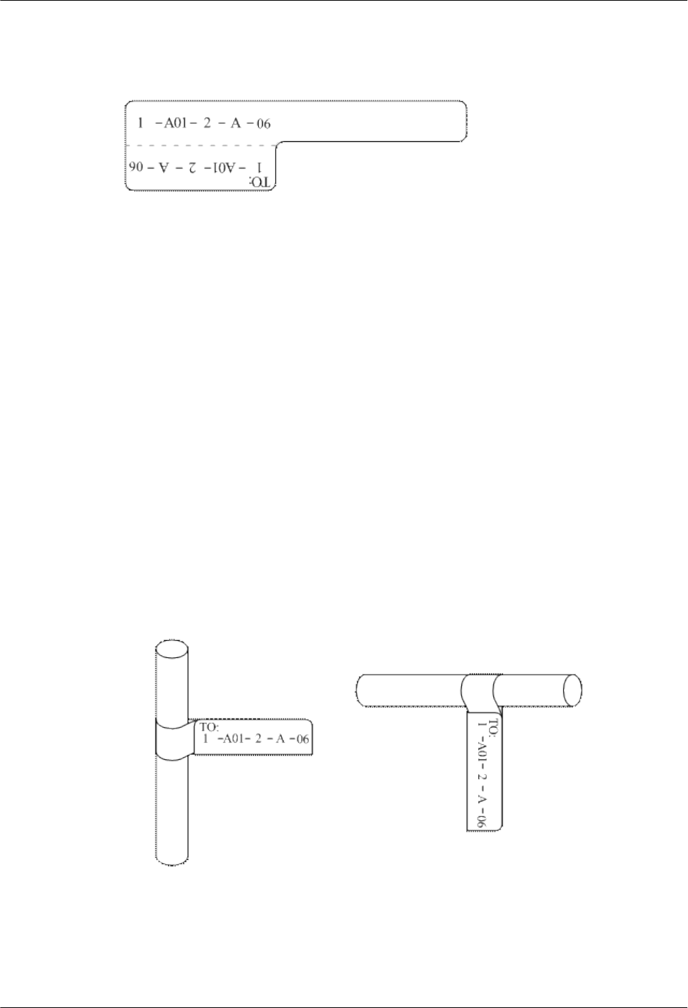
Placement of text on a label is shown in Figure 5-157.
Figure 5-157 Placement of text on a label
5.4.1.5 Attaching Labels
After printing or writing the label, remove the label from the page and attach it to the signal
cable, or the identification plate of the power cable. The methods for attaching labels are
described in the following sections.
Label for Signal Cables
lChoose the place to attach labels.
The label is attached 2 cm (0.79 in.) from the connector on a signal cable. In special
cases (for example, to avoid cable bending or affecting other cables), other positions are
allowed to attach the labels. The rectangular part with text is attached facing right or
downward, as shown in Figure 5-158. The details are as follows:
–The identification card is to the right of the cable in vertical cabling.
–The identification card should be downward when you lay out the cable
horizontally.
Figure 5-158 Text area of the label
lProcedure for attaching labels
Figure 5-159 shows the methods and procedures for attaching labels.
AP4050DN-E
Hardware Installation and Maintenance Guide 5 Appendix
Issue 05 (2018-02-02) Huawei Proprietary and Confidential
Copyright © Huawei Technologies Co., Ltd.
134
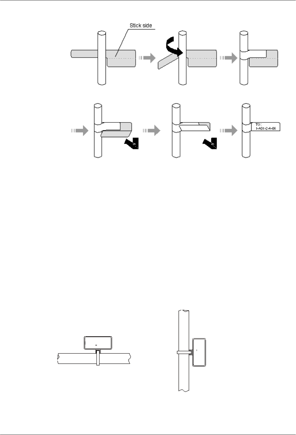
Figure 5-159 Label for signal cables
Power Cable Label
Remove the label from the backing page, and attach it to the identification plate on the cable
tie. The label should be attached to the rectangular flute on the identification plate, and
attached to only one side of the identification plate. The cable ties are bundled at 2 cm (0.79
in.) from the connectors, and other positions are allowed in special circumstances.
Cable ties should be bound on both ends of a cable. After the bundling, the finished
identification plate should be on top of the cable in horizontal cabling, or on the right side of
the cable in vertical cabling, as shown in Figure 5-160. The details are as follows:
lThe identification card is to the right of the cable in vertical cabling.
lThe identification card is on the top of the cable in horizontal cabling. Make sure that the
label is facing out.
Figure 5-160 Binding the label for the power cable
The identification card is on the
top of the cable in horizontal
cabling.
The identification card is to
the right of the cable in
vertical cabling.
TO:
B03 -48V2
TO:
B03 -48V2
Cable
Cable
AP4050DN-E
Hardware Installation and Maintenance Guide 5 Appendix
Issue 05 (2018-02-02) Huawei Proprietary and Confidential
Copyright © Huawei Technologies Co., Ltd.
135
5.4.1.6 Contents of Engineering Labels
Contents of Labels for Power Cables
Labels for power cables are affixed on only one side of the identification plates. On the labels,
there is information (the part after the word "TO:") about the location of the device on the
other end of the cable, like the location of control cabinet, distribution box or power socket.
Contents of Labels for Signal Cables
The two sides of the label affixed on the signal cable carry information about the location of
the ports connected to both ends of the cable. Figure 5-161 shows the information on both
sides of the labels affixed to the signal cables.
lArea 1 contains the location information of the local end of the cable.
lArea 2 (with the word "TO:") contains the location information of the opposite end of the
cable.
lArea 3 has been folded up inside the label.
Figure 5-161 Printed parts on the label for signal cables
Seen from the cabling end of the equipment, the text part of the label is on the right side of the
cable. The side with "TO:" that is facing outside carries the location information of the
opposite end; and the other side carries the location information of the local end.
In other words, the information in Area 1 at one end is the same as the information in Area 2
at the other end of the cable.
5.4.1.7 Precautions for Using Engineering Labels
When using labels, pay attention to the following points:
lWhen printing, writing, or attaching labels, keep the labels clean.
lSince the label paper is made of moistureproof material, ink-jet printers and ink pens
cannot be used to print and write labels.
lLabels should be attached neatly. New-type labels are L-shaped. If they are pasted at
incorrect locations or in the incorrect direction, the appearance of the device is affected.
lPower cable ties should be attached in the same positions on power cables, with
identification plates on the same side.
lThe positions of "up", "down", "left" or "right" are all based on the viewpoint of the
engineering person who is working on the label.
AP4050DN-E
Hardware Installation and Maintenance Guide 5 Appendix
Issue 05 (2018-02-02) Huawei Proprietary and Confidential
Copyright © Huawei Technologies Co., Ltd.
136
5.4.2 Engineering Labels for Optical Fibers
These labels are affixed to the optical fibers that connect the optical interfaces on the boards
in a chassis, or on the device boxes. There are two types of labels for optical cables:
lOne is for the fiber that connects the optical interfaces on two devices.
lThe other is for the fiber that connects the device and the ODF.
5.4.2.1 Labels for the Optical Fibers Connecting Devices
Meaning of the Label
Table 5-27 lists information on both sides of the labels affixed to the optical fibers that
connect two devices.
Table 5-27 Information on labels affixed to the fibers between two devices
Content Meaning Example
MN-B-C-D-
R/T
MN: cabinet
number
M: The cabinet rows from front to back are numbered
from A to Z.
N: The cabinet columns from left to right are numbered
from 01 to 99.
For example, A01 is the cabinet in row A and column
01.
B: chassis
number
Numbered in bottom-up order with two digits, for
example, 01.
C: physical slot
number
Numbered in top-down and left-right order starting
from 01. For example, 01 is the first slot at the top left
of the chassis.
D: optical
interface
number.
Numbered in top-down and left-right order, consistent
with the port sequence number on the device.
R: Receiving
interface
T: optical
transmitting
interface
-
Example of the Label
Figure 5-162 shows a sample label on an optical fiber.
Figure 5-162 Sample label on an optical fiber between two devices
A01 R
TO:
01 05 01
G01 T
01 01 01
AP4050DN-E
Hardware Installation and Maintenance Guide 5 Appendix
Issue 05 (2018-02-02) Huawei Proprietary and Confidential
Copyright © Huawei Technologies Co., Ltd.
137

The meaning of the label is listed in Figure 5-162.
l"A01-01-05-01-R" indicates that the local end of the optical fiber is connected to the
optical receiving interface 01 in slot 5, chassis 01 in the cabinet in row A, column 01 in
the machine room.
l"G01-01-01-01-T" indicates that the opposite end of the optical fiber is connected with
optical transmitting interface 01 in slot 01, chassis 01 in the cabinet in row G, column 01
in the machine room.
5.4.2.2 Labels for the Optical Fibers Connecting the Device and an ODF
Meaning of the Labels
Table 5-28 shows information on both sides of labels attached to an optical fiber between a
device and an optical distribution frame (ODF).
Table 5-28 Information on labels affixed to a fiber between a device and an ODF
Content Meaning Example
MN-B-C-D-
R/T
MN: cabinet
number
For example, A01.
B: chassis
number
Numbered in bottom-up order with two digits, for
example, 01.
C: physical slot
number
Numbered in top-down and left-right order starting
from 01. For example, 01 is the first slot at the top left
of the chassis.
D: optical
interface
number.
Numbered in top-down and left-right order, consistent
with the port sequence number on the device.
R: Optical
receiving
interface
T: optical
transmitting
interface
-
ODF-MN-B-
C-R/T
MN: row
number and
column number
of an ODF
M: The cabinet rows from front to back are numbered
from A to Z.
N: The cabinet columns from left to right are
numbered from 01 to 99.
For example, G01 is the ODF of row G and column
01.
B: row number
of the terminal
device
Range from 01 to 99, for example, 01-01.
AP4050DN-E
Hardware Installation and Maintenance Guide 5 Appendix
Issue 05 (2018-02-02) Huawei Proprietary and Confidential
Copyright © Huawei Technologies Co., Ltd.
138
Content Meaning Example
C: column
number of the
terminal device
R: Optical
receiving
interface
T: optical
transmitting
interface
-
Example of the Label
Figure 5-163 shows a sample label on an optical fiber.
Figure 5-163 Sample label on an optical fiber between the device and the ODF
ODF R
TO:
G01 01 01
A01 R
01 05 01
Meaning of the label in Figure 5-163
l"ODF-G01-01-01-R" indicates that the local end of the optical fiber is connected to the
optical receiving terminal in row 01, column 01 of the ODF in row G, column 01 in the
machine room.
l"A01-01-05-01-R" indicates that the opposite end of the optical fiber is connected to
optical receiving interface 1 in slot 05, chassis 01 in the cabinet in row A, column 01 in
the machine room.
5.4.3 Engineering Labels for Network Cables
Applicable Ranges
The labels can be applied to Ethernet cables.
Label Content
Table 5-29 shows the information on both sides of the labels affixed to Ethernet cables.
You can also decide the label content based on the actual environment. If the device is not
installed in the cabinet, for example, you can remove the cabinet number.
AP4050DN-E
Hardware Installation and Maintenance Guide 5 Appendix
Issue 05 (2018-02-02) Huawei Proprietary and Confidential
Copyright © Huawei Technologies Co., Ltd.
139
Table 5-29 Information on the Ethernet cables
Content Meaning Example
MN-B-C-D MN: cabinet
number
For example, A01 is the first cabinet in row A.
B: chassis
number
Numbered in bottom-up order with two digits, for
example, 01.
C: physical slot
number
Numbered with two digits in top-down and left-
right order. For example, 01.
D: network port
number
Numbered in top-down and left-right orders. For
example, 01.
MN-Z MN: cabinet
number
For example, B02 is the second cabinet in row B.
Z: Location
number
Fill in the location number of the terminal device
on site. If the cable is connected to a device in a
cabinet, specify the serial numbers of the cabinet,
the chassis, and the Ethernet interface of the device.
For example, B02-03-12. If the cable is connected
to the Network Management Station (NMS),
specify the specific location of the NMS.
The contents of the labels for network cables connecting hubs and devices or agents and the
network cables for other purposes should be specified according to actual connections. The
details are as follows:
lFor a network cable connecting a hub and device, the label on the hub end should
indicate the numbers of the chassis and cabinet where the hub resides, and the serial
number on the hub. The label on the device end should indicate the number of the
chassis and cabinet where the device is located. If the device is a standalone device,
provide the specific position of the device.
lFor a network cable connecting a hub and an agent or terminal, the label on the agent or
terminal end should contain the serial number of the network interface. The definitions
of the cabinet number and chassis number are the same as those described in Table 5-29.
lIf the hub is a standalone device without a cabinet or chassis, the label should contain
specific location information that identifies the hub.
The serial number on the hub, the network interface number of the agent or terminal, and the
location of the standalone device should be specified according to actual connections.
Label Example
Figure 5-164 shows a sample label on an Ethernet cable.
Figure 5-164 Sample label on an Ethernet cable
A01
TO:
03 01 01
B02 03 01
AP4050DN-E
Hardware Installation and Maintenance Guide 5 Appendix
Issue 05 (2018-02-02) Huawei Proprietary and Confidential
Copyright © Huawei Technologies Co., Ltd.
140
Meaning of the label in Figure 5-164.
l"A01-03-01-01" indicates that one end of the network cable is connected to network
interface 01 in slot 01, chassis 03 of the cabinet in row A, column 01 in the equipment
room.
l"B02-03-01" indicates that another end of the network cable is connected to network
interface 01 in chassis 03 of the cabinet on row B, column 02 in the equipment room. No
slot number is given.
5.4.4 Engineering Labels for User Cables
Attach labels to both ends of a user cable to indicate the locations of the cable on the device
and main distribution frame (MDF).
Meaning of the Engineering Labels for User Cables
Table 5-30 shows the contents of the labels.
Table 5-30 Contents of the engineering labels for user cables
Content Meaning Example
MN-B-C-D MN: cabinet
number
For example, A01 is the first cabinet in row A.
B: frame number Numbered in the bottom-up order with two digits,
for example, 03.
C: physical slot
number
Numbered with two digits in top-down and left-
right order. For example, 01.
D: cable number Numbered with two digits in top-down and left-
right order. For example, 01.
MDF-MN-B-C MN: row number
and column
number of the
MDF
M: The rows of cabinets from front to back are
numbered from A to Z. N: The columns of cabinets
from left to right are numbered from 01 to 99. For
example, G01 is the MDF of Row G and Column
01.
B: row number of
the terminal
device
Ranges from 01 to 99, for example, 01-01.
C: column number
of the terminal
device
Example of the Label
Figure 5-165 shows a sample label on a user cable.
AP4050DN-E
Hardware Installation and Maintenance Guide 5 Appendix
Issue 05 (2018-02-02) Huawei Proprietary and Confidential
Copyright © Huawei Technologies Co., Ltd.
141
Figure 5-165 Sample label on a user cable
A01
TO:
03 01 01
MDF G01 01 01
The meaning of the label in Figure 5-165 is as follows:
l"A01-03-01-01" indicates that the local end of the user cable is connected to port 1 in
slot 1, chassis 03 of the cabinet in row A, column 01 in the equipment room.
l"MDF-G01-01-01" indicates that the opposite end of the user cable is connected to the
terminal in row 01, column 01 of the MDF in row G, column 01 in the equipment room.
5.4.5 Engineering Labels for Power Cables
5.4.5.1 Engineering Labels for DC Power Cables
These labels are affixed to the DC power cables that provide power supply for cabinets,
including the -48 V, PGND, and BGND cables. Here, the DC power cables also include power
cables and PGND cables.
The labels for DC power cables are affixed to one side of the identification plates on cable
ties. For details of the labels, see Table 5-31.
Table 5-31 Contents of the label
Content Meaning
MN(BC)-
B--48Vn
MN(BC): BC is written right under MN.
B: chassis number, numbered in bottom-up order with two digits, for
example, 01.
N: power socket number, numbered as 1 to 3 in the bottom-up and left-
to-right orders.
On the loaded cabinet side, only MN is used to identify the cabinet.
On the power cabinet side, MN identifies the row and column number
of the power distribution equipment like a control cabinet and
distribution box, and BC identifies the row and column number of the
-48 V connector. If there is no row number or column number, or the
connector can be identified without them, BC can be omitted. It is
unnecessary to identify the row and column number for BGND and
PGND.
MN(BC)-B-
BGND
MN(BC)-B-
PGND
The label only carries location information about the destination direction of the power cable
whereas information about the local end is unnecessary. That is, the label only carries location
information about the opposite equipment, the control cabinet, or the distribution box. Table
AP4050DN-E
Hardware Installation and Maintenance Guide 5 Appendix
Issue 05 (2018-02-02) Huawei Proprietary and Confidential
Copyright © Huawei Technologies Co., Ltd.
142
5-31 lists the information on two -48 V power supplies on the label. The information on other
DC voltages, such as 24 V and 60 V should be given in similar methods.
Make sure that labels are affixed in the correct direction. That is, after the cable ties are
bundled onto the cable, the identification plates with the labels should face up, and the text on
the labels in the same cabinet should be in the same direction. For details, see Figure 5-166.
Figure 5-166 Example of the labels for DC power cables
The meaning of the label in Figure 5-166 is as follows:
lOn the loaded cabinet side, the label "A01/B08--48V2" on the cable indicates that the
cable is -48 V DC supply, which is from the eighth connector in row B of -48 V bus bar
in the cabinet in row A, and column 1 in the equipment room.
lOn the distribution box side, the label "B03--48V2" indicates that the cable is -48 V DC
supply, connected to DC power socket 2 in row B, column 03 in the equipment room.
NOTE
In the power distribution box or the first power cabinet of a row in a transmission equipment room,
every terminal block on the -48 V connector bar has a numeric identification. For example, in the above
label of "A01/B08--48V2", "08" (or sometimes "8") is the numeric identification of the terminal block.
PGND and BGND are two copper bars, on which the terminal blocks are short-circuited.
Therefore, it makes no difference which terminal is connected to them. It is only necessary to
give the row and column of the power distribution box, instead of giving the specific serial
number of the terminal block on the copper bar. For example, if the label on the loaded
cabinet side is "A01-BGND", it means that the power cable is a BGND that connects BGND
copper bar in the power distribution box in row A, column 01 in the machine room.
Information on the labels for PGND cables should be given in a similar way.
5.4.5.2 Engineering Labels for AC Power Cables
These labels are affixed to both ends of an AC power cable that provides AC power supply to
cabinets, including 110/220 V, PGND, and BGND cables. The 110/220 V AC cables and
related PGND and BGND cables are covered with an insulating sheath, so the labels need to
contain only the word "AC" and the cabinet numbers.
The labels for AC power cables are affixed to one side of the identification plates on cable
ties. For details, see Table 5-32.
AP4050DN-E
Hardware Installation and Maintenance Guide 5 Appendix
Issue 05 (2018-02-02) Huawei Proprietary and Confidential
Copyright © Huawei Technologies Co., Ltd.
143
Table 5-32 Label content
Content Meaning
MN-(B)-ACn MN: serial number of the cabinet or the socket where the power is led
in
B: chassis number, numbered in bottom-up order with two digits, for
example, 01.
n: power port number, numbered as 1 to 3 in bottom-up and left-to-right
order.
Serial number of the socket where the power is led in: the location of
the socket is marked according to the actual situation. If the sockets can
be identified by row numbers and column numbers, they can be
numbered following the same rule for the cabinets. If the sockets
cannot be identified by rows and columns, specify the detailed
locations to avoid confusion with other sockets.
The label only carries location information about the opposite equipment and the power
socket; information about the local end is unnecessary.
Make sure that labels are affixed in the correct direction. That is, after the cable ties are
bundled onto the cable, the identification plates with the labels should face up, and the text on
the labels in the same cabinet should be in the same direction, as shown in Figure 5-167.
Figure 5-167 Labels for AC power cables
Label on the loaded cabinet side
(indicating the position of the cable
on the power distribution box)
Label on the distribution box side
(indicating the position of the cable
on the loaded cabinet side)
Meaning of the label in Figure 5-167.
lOn the equipment cabinet side, the label marked "A01-AC1" indicates that the power
cable is connected to the first AC power socket of row A and column 01 in the
equipment room.
lOn the power socket side, the label marked "B01-AC1" indicates that the power cable is
connected to the first AC power socket in the cabinet of row B and column 01 in the
equipment room.
5.5 Guide to Using Optical Modules
AP4050DN-E
Hardware Installation and Maintenance Guide 5 Appendix
Issue 05 (2018-02-02) Huawei Proprietary and Confidential
Copyright © Huawei Technologies Co., Ltd.
144
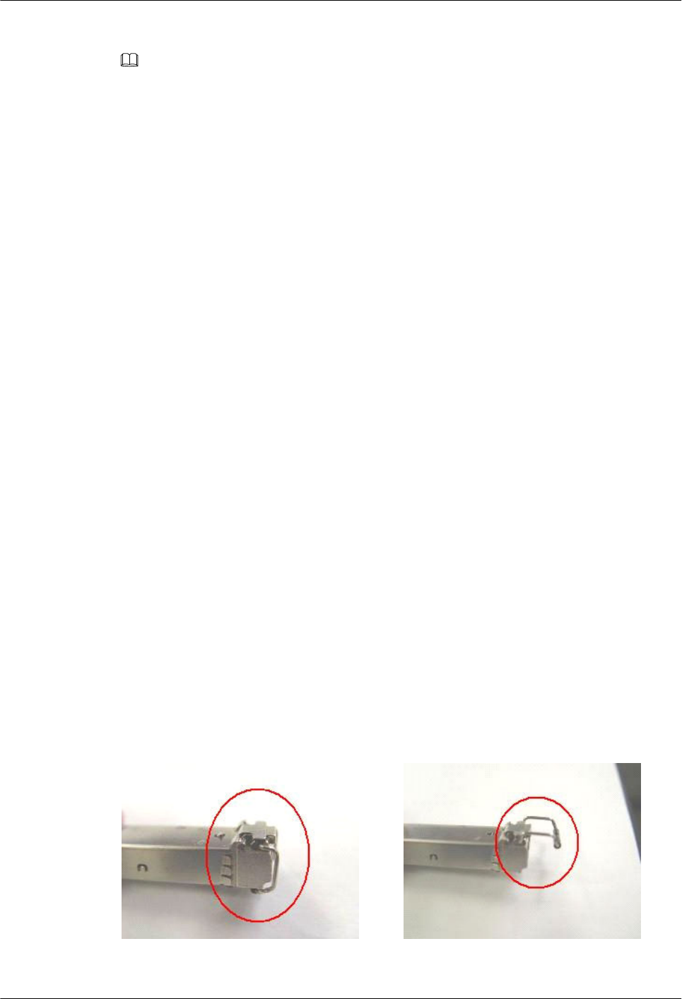
Common Faults of an Optical Module
NOTE
The system may fail to obtain information about non-Huawei-certified optical modules or obtain incorrect
information. You are advised to use Huawei-certified optical modules. Obtain the electronic label of the
optical module and contact technical support personnel to confirm whether it is a Huawei-certified optical
module.
1. An optical module is not completely installed in position.
If the optical module is not completely installed in position and the latch boss is not
secured, the device cannot identify the optical module. After the optical module works
for a long time, it will be ejected under external stress.
2. The optical receptacle on an optical module is contaminated.
If an optical module is not cleaned or protected properly, contaminants may accumulate
on the fiber pin in the optical module. As a result, the coupling efficiency is reduced,
optical signals are cut off, or even worse, the surface of the fiber pin is damaged
permanently.
3. An optical module is burnt.
If high-power optical signals (caused by an optical time domain reflectometer or self-
loop test) are transmitted through an optical module that is used for long-distance
transmission but no optical attenuator is used, the optical power will exceed the overload
power of the avalanche photodiode (APD). Then the optical module is burnt.
The preceding faults lead to temporary or long-term cut-off of optical signals; or even cause
permanent damages to the optical module, affecting communication services.
Measures to Prevent a Loosened Optical Module
1. When installing an optical module, insert it in position. If you hear a click or feel a slight
shake, it indicates that the latch boss is secured.
If the latch boss is not secured, the gold finger of the optical module is not in good
contact with the connector on the board. In this case, the link may be connected but
optical signals will be cut off or the optical module will be loosened when the optical
module is shaken or hit.
2. Figure 5-168 shows the release handle on an optical module when it is open and closed.
When inserting the optical module, make sure that the release handle is closed. At this
time, the latch boss locks the optical module. After the optical module is inserted, try
pulling it out to see if it is installed in position. If the optical module cannot be pulled
out, it is secured.
Figure 5-168 State of the release handle
Close the release handle Open the release handle
AP4050DN-E
Hardware Installation and Maintenance Guide 5 Appendix
Issue 05 (2018-02-02) Huawei Proprietary and Confidential
Copyright © Huawei Technologies Co., Ltd.
145
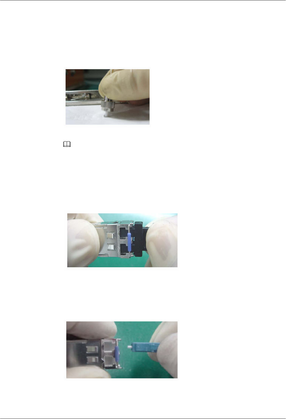
Measures to Prevent Receptacle Contamination
1. Cleaning tissues must be prepared on site. You need to clean the optical connector before
inserting it in the receptacle. This protects the receptacle against contamination on the
surface of the optical connector.
Figure 5-169 Cleaning optical fibers with special cleaning tissues
NOTE
Place at least three cleaning tissues on the work bench. As shown in Figure 5-169, wipe the end of
an optical connector from left to right or from right to left on a cleaning tissue, and then move the
connector end to the unused part of the cleaning tissue to continue.
2. Cover an unused optical module with a protective cap to prevent dust, as shown in
Figure 5-170.
Figure 5-170 Installing a protective cap
If no protective cap is available, use fibers to protect the optical module, as shown in
Figure 5-171.
Figure 5-171 Using fibers to protect an optical module
3. Cover unused optical connectors with protective caps, as shown in Figure 5-172, and
then lay out fibers on the fiber rack or coil them in a fiber management tray to prevent
fibers from being squeezed.
AP4050DN-E
Hardware Installation and Maintenance Guide 5 Appendix
Issue 05 (2018-02-02) Huawei Proprietary and Confidential
Copyright © Huawei Technologies Co., Ltd.
146
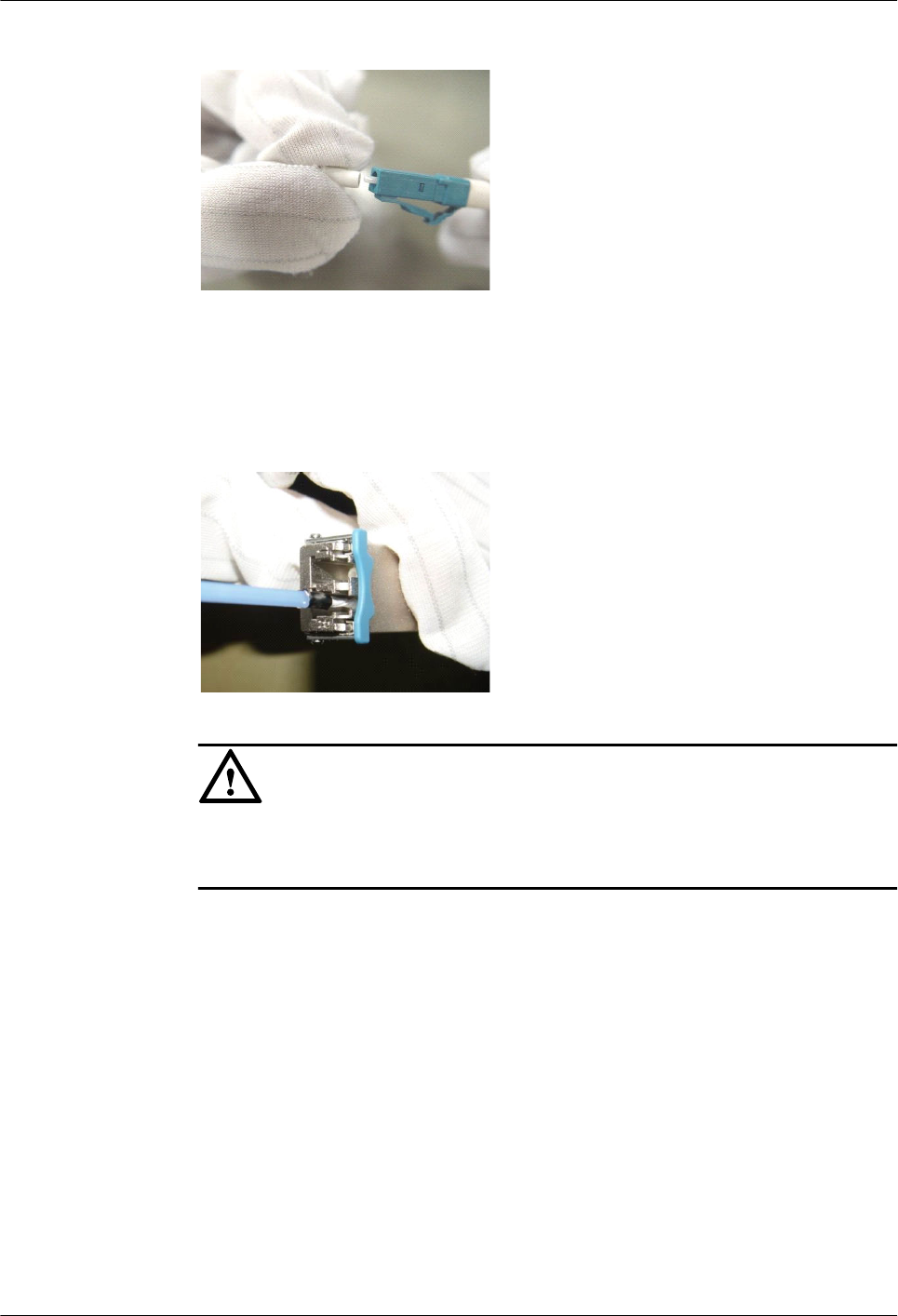
Figure 5-172 Installing a protective cap on a fiber
4. If a receptacle or an optical connector has not been used for a long time and is not
covered with a protective cap, you need to clean it before using it. Clean a receptacle
with a cotton swab, as shown in Figure 5-173. Clean an optical connector with cleaning
tissues.
Figure 5-173 Cleaning a receptacle with a cotton swab
NOTICE
When cleaning a receptacle, insert the cotton swab and turn it slowly in the receptacle.
Do not use too much strength because the receptacle may be damaged.
5. If optical signals are lost during the operation of a device, use the preceding method to
clean the receptacle or the optical connector. In this manner, the possibility of
contamination can be excluded.
Measures to Prevent an Optical Module from Being Burnt
1. Before using an optical time-domain reflectometer (OTDR) to test the connectivity or the
attenuation of optical signals, disconnect the optical fibers from the optical module.
Otherwise, the optical module will be burnt.
2. When performing a self-loop test, use an optical attenuator. Do not loosen the optical
connector instead of the optical attenuator.
Precautions
1. The optical connector should be vertically inserted in the receptacle to avoid damages to
the receptacle.
AP4050DN-E
Hardware Installation and Maintenance Guide 5 Appendix
Issue 05 (2018-02-02) Huawei Proprietary and Confidential
Copyright © Huawei Technologies Co., Ltd.
147
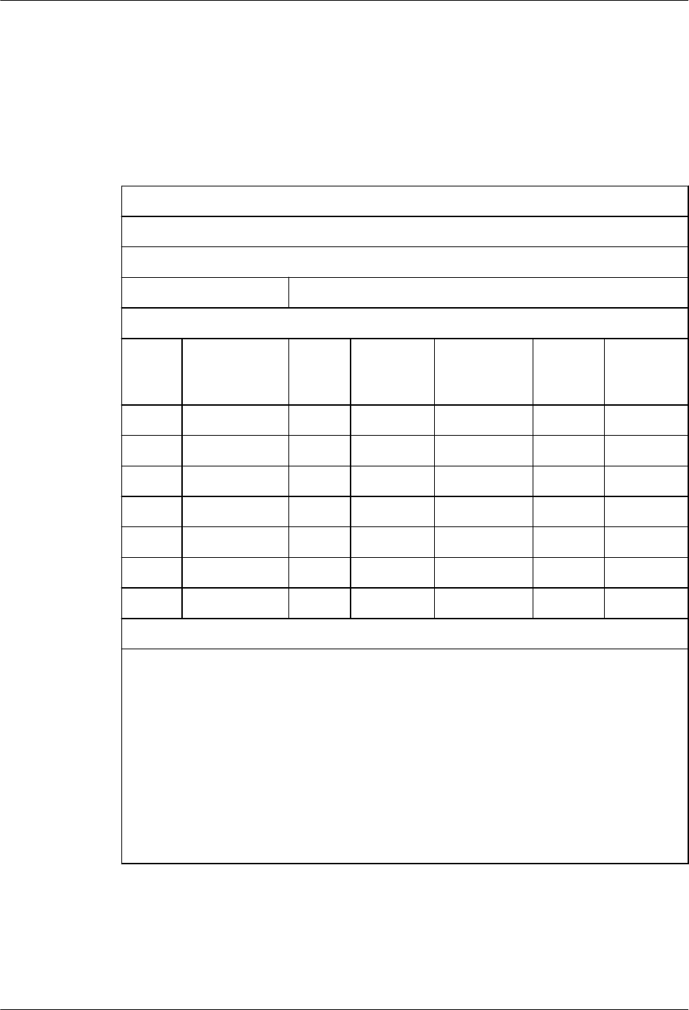
2. Fibers must be inserted into optical modules of the corresponding type. That is,
multimode fibers must be inserted into multimode optical modules, and single mode
fibers must be inserted into single mode optical modules. If a fiber is inserted into an
optical module of a different mode, faults may occur. For example, optical signals will
be lost.
5.6 Fault Tag
*Customer name:
Address:
Contact person:
Tel.: Fax:
Category*: □ RMA □ Return □ Analysis
BOM
Code
Product
Description
Bar
Code*
Fault
Occurring
Date*
Description
of the Fault
Phenomena*
Category
No.*
Software
Version*
Reasons for Repairing (Category No.):
Category No. includes the following eight types:
F001 - Wear out damaged (◊ In warranty Period ◊ Out of warranty period)
F002 - Deployment damaged
F003 - Intransit damaged
F004 - Version upgrade
F005 - Batch replace
F007 - Overdue spare parts inspecting
F008 - Others
F011 - Running circumstance change
AP4050DN-E
Hardware Installation and Maintenance Guide 5 Appendix
Issue 05 (2018-02-02) Huawei Proprietary and Confidential
Copyright © Huawei Technologies Co., Ltd.
148
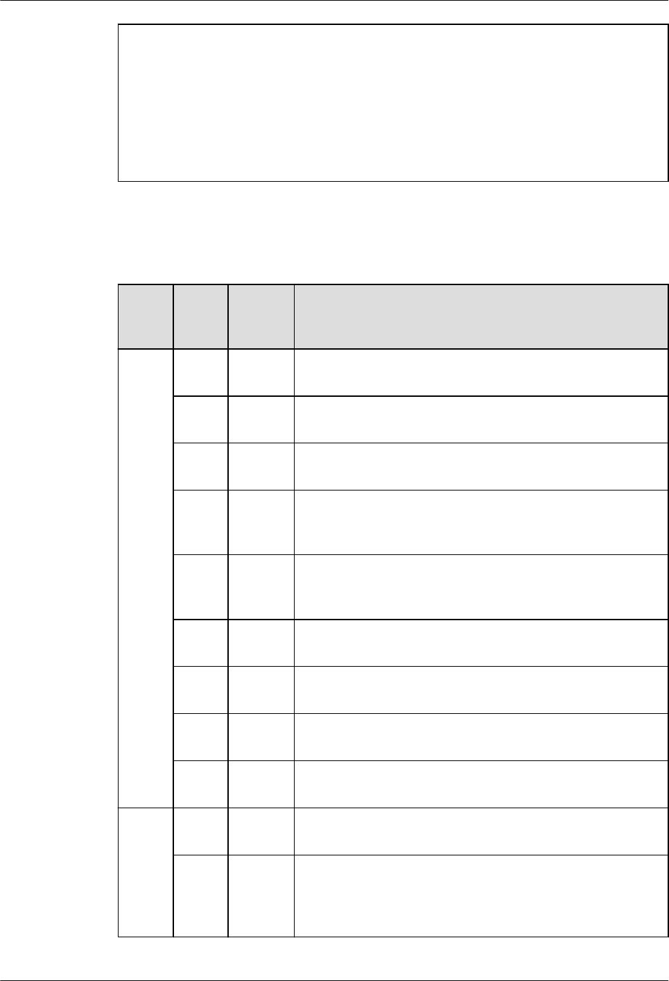
Note:
lFor optical interface cards returned, the optical interfaces should be covered with
protection caps.
lIn general, the analysis card will not be returned to you. If you have any special
requirements, please contact Huawei.
lOne Fault Tag should be adapted in one return category, such as RMA/Return/Analysis.
lThe items marked with "*" are the mandatory fields that you must fill in.
5.7 Installation Checklist
Com
pone
nt
No.
Applic
able
Scope
Check Item
AC 1Indepen
dent AC
The air vent of the device is free from blockage to ensure
normal heat dissipation.
2Indepen
dent AC
The power modules are securely installed with their captive
screws tightly fixed.
3Indepen
dent AC
Four rubber pads are attached to specified positions on the
bottom of the AC before it is placed on a desk.
4Indepen
dent AC
The AC is secured in the cabinet or rack by rack-mounting
brackets or guide rails (or trays), and floating nuts are
correctly secured.
5 AC card
The AC card is secured in the cabinet or rack by guide rails
or trays, and the guide rails or trays and floating nuts are
correctly secured.
6 AC card The AC card is correctly inserted into the device slot and
secured using the ejector lever.
7 AC card No pins on the backplane are bent when the AC card is
installed.
8Indepen
dent AC
The AC is grounded using a ground cable, meeting surge
protection requirements.
9Indepen
dent AC
When the AC directly connects to APs, location IDs of the
APs are provided at the cable connection points.
PoE
power
supply
1 General The proper PoE switch or power adapter is selected, meeting
AP power supply and onsite environment requirements.
2 General
To ensure that the PoE power meets requirements, the PoE
power supply device and APs must be connected through
CAT5E and CAT6E network cables, and the cable length
cannot exceed 100 m.
AP4050DN-E
Hardware Installation and Maintenance Guide 5 Appendix
Issue 05 (2018-02-02) Huawei Proprietary and Confidential
Copyright © Huawei Technologies Co., Ltd.
149

Com
pone
nt
No.
Applic
able
Scope
Check Item
3 General Labels must be made for the PoE power cable to identify AP
locations.
4 General Leave a 20 cm space between PoE power adapters to ensure
normal heat dissipation.
5 General The PoE switch is correctly grounded with the ground cable.
6 General
Reserve a few downlink network interfaces for the PoE
switch (for example, connect at most 20 APs to a 24-port
switch) for future capacity expansion.
7 General
You are advised to configure dual power modules for a PoE
switch for power redundancy backup and providing power
for more APs.
AP
1 General
The AP installation positions comply with the network
planning report and APs cannot be installed in environments
with strong electrical or magnetic interference or corrosive
materials. If the onsite environment does not meet
requirements, adjust the AP installation positions properly.
2 General The devices are installed correctly, securely, without
damages or paint peeling. Screws are tightened.
3 General
Leave at least 20 cm space at the cable outlet and top
(convex) of the AP to facilitate commissioning, maintenance,
and heat dissipation. APs that dissipate heat from the rear
must be fixed using mounting brackets in wall mounting
scenarios. Ensure that there is a certain space between the
APs and wall to facilitate heat dissipation.
4 General
APs with built-in antennas should be installed in open areas
and there should be no obvious obstruction in the coverage
direction of the main lobe. The main lobe of built-in antennas
faces the top (convex).
5 General The APs and antennas are neatly installed, without affecting
the overall layout of the environment.
6Indoor
AP
Indoor APs are placed far away from windows and in dry
environments with little dust and good ventilation. There
should be no inflammable materials in rooms. The indoor
temperature and humidity must be within acceptable ranges.
7Indoor
AP
When being mounted to a ceiling, the APs must be fixed
using the matching mounting brackets. The APs cannot be
hung in the air or placed directly on the ceiling. When the
APs are mounted to a wall, the bottom of the APs should be
at least 30 mm from the ground. The APs should be installed
in places out of reach of people.
AP4050DN-E
Hardware Installation and Maintenance Guide 5 Appendix
Issue 05 (2018-02-02) Huawei Proprietary and Confidential
Copyright © Huawei Technologies Co., Ltd.
150

Com
pone
nt
No.
Applic
able
Scope
Check Item
8Outdoor
AP
When two or more APs are installed in the same area, they
must be installed in the same vertical or horizontal line with
certain spacing greater than 15 mm.
9 General
Dustproof, waterproof, and anti-theft measures are taken and
the devices are kept clean. The APs are secured using the
security locks (separately purchased) based on onsite
situations and customer requirements. If APs are placed in a
network box, ensure that the box is well-ventilated, clean,
and dustless, and the ventilation holes are not blocked.
10 Indoor
AP
Indoor APs should be mounted on walls with network ports
downwards to prevent device damages caused by water drops
or other liquid. Install the device in a site that is free from
leaking or dripping water, heavy dew, and humidity, and take
protective measures to prevent water from flowing into the
equipment along the cable.
11 Outdoor
AP
When an outdoor AP is installed against a wall or pole, keep
the indicator downwards for easy observation.
12 General
Use waterproof labels to mark the registration names of APs
on the AC, as well as their channels and IP addresses. The
lables should be attached to the front of the APs for easy
observation.
13 General
Record AP installation positions, MAC addresses, interfaces
of uplink PoE switches, and IP addresses (APs use fixed IP
addresses) into a table.
14 Indoor
AP
The devices required during indoor AP installation, such as
the splitter, coupler, and antennas are operated in accordance
with specifications.
15 General The APs using a metal shell (with a ground point) must be
properly grounded.
16 Outdoor
AP Unused radio ports should be installed with 50 Ω RF loads.
17 Outdoor
AP
Take lightning protection measures on outdoor APs (the
outdoor APs have built-in 5 kV surge protectors. If
customers require a higher surge protection capability on the
feeder ports, they can purchase additional surge protective
devices, which need to be separately grounded). The APs
should be located in the protection scope (within a 45-degree
angle) of a lightning rod.
18 Outdoor
AP
When an AP is mounted to a pole, the distance between the
AP and the top of pole should be at least 30 cm.
AP4050DN-E
Hardware Installation and Maintenance Guide 5 Appendix
Issue 05 (2018-02-02) Huawei Proprietary and Confidential
Copyright © Huawei Technologies Co., Ltd.
151

Com
pone
nt
No.
Applic
able
Scope
Check Item
Signal
cable 1 General
Routes of signal cables comply with the engineering design
document. The signal cables are correctly connected to
facilitate maintenance and capacity expansion.
2 General Radio ports of an AP are correctly connected to radio ports
A/B/C of antennas.
3 General
Signal cable connectors are correctly installed and securely
connected to the device. Wires of each signal cable are
securely cramped in the connectors and pass connectivity
tests.
4 General
Signal cables are orderly routed and not crossed, twisted, or
winded (cables can be crossed at 1 m out of the cabinet). The
bend radius of cables meets requirements, and the cables are
not excessively bent.
5 General
Signal cables are not damaged or broken and have no splices.
Sufficient cable length is reserved. The reserved cables are
twined and placed properly to facilitate subsequent
maintenance.
6Indoor
AP
The optical, power, network, and feeder cables are bundled
using straps (one strap every 0.5 m) and securely fastened.
7Outdoor
AP
The signal cables shall be bundled at even intervals (about
1000 mm), not too tight or too loose. The cables shall be
bundled properly with cable ties placed in neat order. Cut off
redundant cable ties and remove burrs from them to avoid
injuries. The cables shall be fixed using fasteners or ageing-
resistant outdoor metal binding straps.
8 General
Keep the signal cables away from heat sources and use heat
insulation materials to insulate the cables from the heat
sources. Do not place signal cables on the air vents of the
cabinet to avoid affecting subrack heat dissipation or cable
lifetime.
AP4050DN-E
Hardware Installation and Maintenance Guide 5 Appendix
Issue 05 (2018-02-02) Huawei Proprietary and Confidential
Copyright © Huawei Technologies Co., Ltd.
152
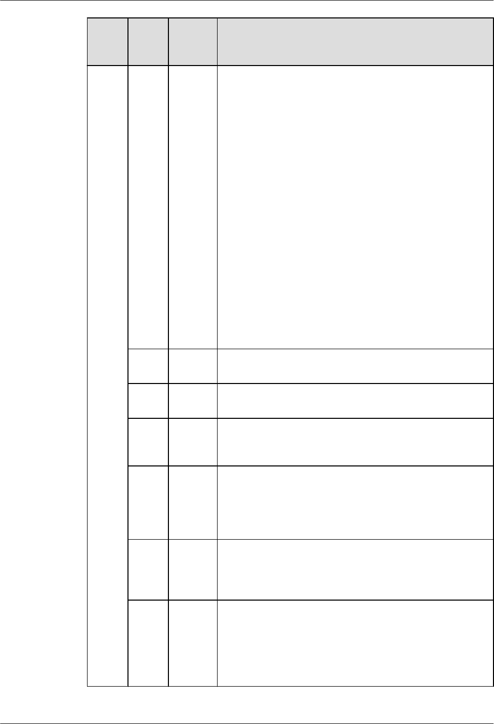
Com
pone
nt
No.
Applic
able
Scope
Check Item
9 General
Pigtail layout should meet the following requirements:
lPigtails are not strained or twisted at the bent parts. They
are bundled by binding tape with appropriate force.
lPigtails can be pulled back and forth easily inside the
cable tie and are not bent at a right angle.
lPigtails are not squeezed by other cables or objects.
lThe flange must be fixed.
lPigtails are protected with protective tubes or enveloped
in troughs when they are routed outside the cabinet. The
protective tubes are bundled and processed to prevent
cutting.
lThe optical fiber cannot be folded or twisted, and the
pigtail cannot be squeezed. The binding diameter of an
optical fiber must be larger than 6 cm.
lThe pigtail connection points must be clean and dustless.
Fiber connectors and optical ports that are not used must
be protected with protective caps or plugs. Cleaning must
be carried out in strict accordance with Huawei tool
specifications.
10 General The feeder cables shall not be bent or twisted, with no copper
wire exposed.
11 General The feeder cable connectors comply with corresponding
standards and are correctly connected, without looseness.
12 General
The feeder cables, power splitter, coupler, and surge
protective devices are connected correctly and reliably in
accordance with specifications.
13 General
Strong current and weak current cables are routed separately.
The power cables, ground cables, and signal cables are
bundled and routed separately (with a spacing of more than
30 mm) to prevent electrical or magnetic interference. Use
shielded cables in places with strong interference.
14 General
When routing cables in walls, place the cables in the cable
troughs or pipes and fix the cables using pipe straps. For non-
metal corrugated pipes, the fixing distance should be about
1000 mm.
15 Outdoor
AP
All outdoor connectors or feeder cable connectors are
properly sealed to prevent water. Wrap the cable using one-
layer PVC insulation tape, three-layer waterproof tape, and
then three-layer PVC insulation tape. The tape shall be
attached evenly and neatly. The network cables shall be
covered with waterproof PG tubes.
AP4050DN-E
Hardware Installation and Maintenance Guide 5 Appendix
Issue 05 (2018-02-02) Huawei Proprietary and Confidential
Copyright © Huawei Technologies Co., Ltd.
153

Com
pone
nt
No.
Applic
able
Scope
Check Item
16 Outdoor
AP
Cable connectors are secured on cables and sealed to prevent
water intrusion. The outlets of cable conduits on a wall are
sealed by waterproof and flame-retardant materials. Drip
loops meeting the minimum bending radius requirement are
made on the network cable segment that stretches indoor.
17 Outdoor
AP Do not deploy cables overhead between two buildings.
18 General
Waterproof labels (providing device names and cable
directions) are filled and attached to signal cables correctly.
Each label is attached 20 mm to 100 mm from the
corresponding cable connector.
19 Outdoor
AP
Surge protection measures are taken in the places where the
outdoor APs are installed. The outdoor APs, antennas, and
signal cables are deployed within 45-degree protection area
of a lightning rod.
20 Outdoor
AP
The bare wires of network and feeder cables should be
covered by the winding pipes, flexible metal conduit, PVC
pipes, or galvanization pipes. The cable outlet and inlet are
sealed to prevent dusts.
Anten
na 1 General
The installation positions of antennas should comply with the
engineering design and antennas should be securely and
reliably installed.
2 General
There should be no obstacles in the major coverage direction
of antennas. The direction and downlink tilt of antennas
should be adjusted based on the coverage targets.
3 General There should not be metal subjects within 1 m around an
outdoor omnidirectional antenna.
4 General The azimuth deviation of a directional antenna should be
within 5 degrees and the tilt deviation within 0.5 degree.
5Outdoor
antenna
The antennas are fixed using special support that supports
installation of surge protection devices and shall be located
within a 45 degree protection angle of a lightning rod. When
an antenna is mounted to a pole, the distance between the
antenna and top of the pole should be at least 30 cm.
6Outdoor
antenna
Take waterproof measures on connectors of the antennas and
feeder cables and keep the drain holes of antennas
downwards.
AP4050DN-E
Hardware Installation and Maintenance Guide 5 Appendix
Issue 05 (2018-02-02) Huawei Proprietary and Confidential
Copyright © Huawei Technologies Co., Ltd.
154

Com
pone
nt
No.
Applic
able
Scope
Check Item
7Outdoor
antenna
The pole used in antenna mounting should meet the
following requirements:
Pole height: ≥ 2000 mm
Bottom pole diameter: ≥ 220 mm
Top pole diameter: ≥ 120 mm
Pole thickness: ≥ 6 mm
Depth of foundation: ≥ 1500 mm
The pole deployed outdoors must be reinforced with hot-dip
zinc to prevent water corrosion and rust.
8Outdoor
antenna
It is recommended that at most three APs or antennas be
mounted to the same pole. The APs or antennas mounted to
the same pole should meet the following requirements:
lThe vertical distance should be at least 3.5 m between
adjacent 2.4G antennas and 2 m between adjacent 5G
antennas.
lThere should be at least 1 m vertical distance between
antennas that work on the same frequency band and
belong to different APs.
9Outdoor
antenna
When outdoor APs use single-polarized antennas, the
horizontal distance between 2.4G antennas should be at least
1 m and that between 5G antennas should be at least 0.5 m.
10 Outdoor
antenna
If multiple APs are mounted to different poles, the APs
should provide signal coverage in the same direction or in
back-to-back mode to ensure that main lobe of antennas on
different APs do not face each other.
Recommended AP distance:
≥ 44 m (APs provide signal coverage in the same direction)
≥ 6 m (APs provide distance in back-to-back mode)
Power
and
groun
d
cables
1 General The female connectors of power cables connecting to the
device are fixed using a locking latch.
2 General The power cables and ground cables are correctly connected.
3 General The power cables and ground cables are complete and not
spliced.
4 General
The excess of power cables or ground cables are trimmed off
without any coils. The power cables connecting the delivered
surge protection boxes and devices cannot be cut. These
power cables can be coiled.
5 General Power cables and ground cable are separated from the signal
cables.
AP4050DN-E
Hardware Installation and Maintenance Guide 5 Appendix
Issue 05 (2018-02-02) Huawei Proprietary and Confidential
Copyright © Huawei Technologies Co., Ltd.
155
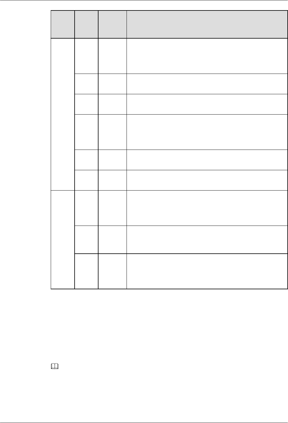
Com
pone
nt
No.
Applic
able
Scope
Check Item
6 General
Power cables and ground cables are routed straightly and
properly bundled, with sufficient slack at the bend part. If the
cables are fixed on a sharp mechanical part, take protection
measures.
7 General The equipotential cables between the attaching cabinets shall
be securely connected.
8 General The lugs for the power cables and ground cables are soldered
or crimped securely.
9 General
The lugs and bare wires of power cables and ground cables
are tightly wrapped with tubes or insulation tape without any
exposed copper wire. Flat washers and spring washers are
installed correctly.
10 General Labels are filled and attached to power cables and ground
cables correctly.
11 General Power cables deployed outdoors must be covered by PVC
tubes.
Optica
l
modul
e
1 General
A single-mode fiber can only be used with a single-mode
optical module while a multimode optical fiber can only be
used with a multimode optical module. On most optical
modules, the fibers of different types cannot be used together.
2 General
The labels of pluggable optical modules are smoothly
attached and intact, and cannot be covered by the optical
modules.
3 General
If a short-distance optical fiber is used for a long-distance
optical module, especially in loopback scenarios, use an
optical attenuator to prevent the optical module from being
burnt.
5.8 Guide to Making Drip Loops
To prevent water from flowing into devices along cables, you need to take waterproof
measures, for example, create a drip loop on a cable. As an example, the following describes
how to create drip loops on network cables connected to a device in different directions.
NOTE
lWhen a device is installed in a harsh environment or its ports face upward, follow outdoor
waterproof standards to lay out indoor cables. For details, see "Cable Connection" in the
AP6510DN&AP6610DN Hardware Installation and Maintenance Guide.
lThe network cable directions in the description below are relative to an AP.
lIf a cable is downward, no drip loop is required.
AP4050DN-E
Hardware Installation and Maintenance Guide 5 Appendix
Issue 05 (2018-02-02) Huawei Proprietary and Confidential
Copyright © Huawei Technologies Co., Ltd.
156
Downward Port, Upward Cable
≥50mm
Ķ
≤100mm
ǹ
Upward Port, Upward Cable
≥50mm
Ķ
≤100mm
ǹ
Horizontal Port, Upward Cable
≥50mm
≤100mm
ǹ
Ķ
Bending Radius Requirements
lThe bending radius of a 7/8'' feeder must be more than 250 mm, and that of a 5/4'' feeder
must be more than 380 mm.
AP4050DN-E
Hardware Installation and Maintenance Guide 5 Appendix
Issue 05 (2018-02-02) Huawei Proprietary and Confidential
Copyright © Huawei Technologies Co., Ltd.
157

lThe bending radius of a 1/4" jumper, 1/2" super-flexible jumper, and 1/2" common
jumper must be greater than 35 mm, 50 mm, and 127 mm, respectively.
lThe bending radius of a ground cable must be greater than or equal to five times the
cable diameter.
lThe bending radius of a network cable must be greater than or equal to five times the
cable diameter (that is, 50 mm).
5.9 Power Adaptation Solution
Select a suitable power supply mode as required.
DC Power Supply
Table 5-33 Mapping between device models and DC power adapters
Pa
rt
Nu
m
be
r
Name Vendor Applicable Device
02
31
0JF
D
S5700
Series,ES0W2PSD0150,150W DC
Power Module
HUAWEI AC6605
02
22
011
9
Adapter,0degC,40degC,90V,264V,
+48V/2.08A
FSP AD9430DN-12
AP2050DN,
AP2050DN-E, and
AP2050DN-S
AP7050DN-E
R250D-E
02
22
09
35
Adapter,-25degC,50degC,90V,290V,
56V1.07A,C8
Ktec / HONOR AP2050DN,
AP2050DN-E, and
AP2050DN-S
AP4051TN
AP6052DN
AP7052DN,
AP7152DN,
AP7052DE
R250D-E
02
22
08
64
AC/DC
Adapter--5degC-45degC-90V-270V-
12V/2A-Europe Standard-DC inlet
HuntKey /
SHILONG FUHUA
AP1050DN-S
AP4030TN,
AP4050DN,
AP4050DN-S,
AP4050DN-E,
AP4050DN-E
Hardware Installation and Maintenance Guide 5 Appendix
Issue 05 (2018-02-02) Huawei Proprietary and Confidential
Copyright © Huawei Technologies Co., Ltd.
158

Pa
rt
Nu
m
be
r
Name Vendor Applicable Device
02
22
08
65
AP4050DN-HD,
AP4051DN,
AP4151DN, and
AP430-E
AP5030DN-C
AP6050DN and
AP6150DN
AP7050DE
R450D
AC/DC
Adapter--5degC-45degC-90V-270V-
12V/2A-UK Standard-DC inlet
HuntKey /
SHILONG FUHUA
02
22
08
66
AC/DC
Adapter--5degC-45degC-90V-270V-
12V/2A-Australia Standard-DC inlet
HuntKey
02
22
08
67
Adapter,-5degC,45degC,90V,270V,
12V/2A
HuntKey /
SHILONG FUHUA
02
22
08
68
AC/DC
Adapter--5degC-45degC-90V-270V-
12V/2A-China Standard-DC inlet
HuntKey /
SHILONG FUHUA
02
22
08
69
AC/DC
Adapter--5degC-45degC-90V-270V-
12V/2A-Brazil Standard-DC inlet
HuntKey
02
22
08
70
Adapter,-5degC,45degC,90V,270V,
12V/2A,India Plug, DC Plug
HuntKey /
SHILONG FUHUA
AC Power Supply
Table 5-34 Mapping between device models and AC power adapters
Par
t
Nu
mb
er
Name Vendor Applicable Device
023
10J
FA
S5700
Series,ES0W2PSA0150,150W AC
Power Module
HUAWEI AC6605
AP4050DN-E
Hardware Installation and Maintenance Guide 5 Appendix
Issue 05 (2018-02-02) Huawei Proprietary and Confidential
Copyright © Huawei Technologies Co., Ltd.
159

Par
t
Nu
mb
er
Name Vendor Applicable Device
021
309
83
AC/DC power
module--25degC-55degC-90V-264V
-12V/10A,-53.5V/7.1A
FSP/VAPEL AC6605
AP4050DN-E
Hardware Installation and Maintenance Guide 5 Appendix
Issue 05 (2018-02-02) Huawei Proprietary and Confidential
Copyright © Huawei Technologies Co., Ltd.
160

PoE Power Supply
Table 5-35 Mapping between device models and PoE power adapters
Par
t
Nu
mb
er
Name Vendor Applicable Device
022
203
69
Adapter,-40degC~50degC,
90V~264V,54V/0.65A,C8/RJ45,GE
HuntKey /
SHILONG FUHUA
AP2010DN,
AP2030DN,
AP2050DN,
AP2050DN-S,
AP2050DN-E
AP3010DN
AP4030DN,
AP4030TN,
AP4050DN,
AP4050DN-E,
AP4050DN-S,
AP4051DN,
AP4051TN,
AP4130DN,
AP4151DN
AP5010DN,
AP5010SN,
AP5030DN,
AP5030DN-C,
AP5130DN
AP6010SN,
AP6010DN,
AP6050DN,
AP6052DN,
AP6150DN,
AP6510DN,
AP6310SN
AP7030DE,
AP7050DE,
AP7052DE,
AP7052DN,
AP7110DN,
AP7110SN,
AP7152DN
AP8030DN,
AP8050DN,
AP8050DN-S,
AP8050TN-HD,
AP8130DN,
AP8130DN-W,
AP8150DN
AP4050DN-E
Hardware Installation and Maintenance Guide 5 Appendix
Issue 05 (2018-02-02) Huawei Proprietary and Confidential
Copyright © Huawei Technologies Co., Ltd.
161

Par
t
Nu
mb
er
Name Vendor Applicable Device
AP9330DN
R240D, R250D,
R250D-E, R450D
AT815SN
022
201
54
Adapter,-25degC,60degC,90V,264V,
56V/1.52A,C8/RI45,POE
ADAPTER
FSP AD9430DN-12
AP6052DN,
AP6510DN
AP7030DE,
AP7050DE,
AP7052DE,
AP7052DN,
AP7110DN,
AP7110SN,
AP7152DN
AP8030DN,
AP8130DN,
AP8130DN-W,
AP8050DN,
AP8150DN,
AP8050DN-S,
AP8050TN-HD,
AP8082DN,
AP8182DN
AP8030DN,
AP8130DN,
AP8130DN-W,
AP8050DN,
AP8150DN,
AP8050DN-S,
AP8082DN,
AP8182DN
021
311
68
AC-DC Power,-5degC,45degC,90V,
264V,48V/0.42A
SHILONG FUHUA AT815SN
PSE Power Supply
lSwitches, ACs, and APs supporting the PoE out function can be used as power sourcing
equipment (PSE) to supply power to connected powered devices (PDs). Ensure that the
PoE out power of a PSE meet requirements of PDs.
AP4050DN-E
Hardware Installation and Maintenance Guide 5 Appendix
Issue 05 (2018-02-02) Huawei Proprietary and Confidential
Copyright © Huawei Technologies Co., Ltd.
162

lAn S5720-14X-PWH-SI-AC (part number: 02350MTV) can supply UPoE power to
AP7050DN-Es.
AP4050DN-E
Hardware Installation and Maintenance Guide 5 Appendix
Issue 05 (2018-02-02) Huawei Proprietary and Confidential
Copyright © Huawei Technologies Co., Ltd.
163

Wireless LAN Access Point is only used indoors
This device complies with part 15 of the FCC Rules. Operation is subject to the following two
conditions: (1) This device may not cause harmful interference, and (2) this device must
accept any interference received, including interference that may cause undesired operation.
Changes or modifications not expressly approved by the manufacturer could void the user’s
authority to operate the equipment.
The antenna(s) used for this transmitter must not be co-located or operating in conjunction
with any other antenna or transmitter.
This equipment has been tested and found to comply with the limits for a Class B digital device,
pursuant to part 15 of the FCC Rules.
These limits are designed to provide reasonable protection against harmful interference in a
residential installation. This equipment generates, uses and can radiate radio frequency
energy and, if not installed and used in accordance with the instructions, may cause harmful
interference to radio communications. However, there is no guarantee that interference will not
occur in a particular installation. If this equipment does cause harmful interference to radio or
television reception, which can be determined by turning the equipment off and on, the user is
encouraged to try to correct the interference by one or more of the following measures:
Reorient or relocate the receiving antenna.
Increase the separation between the equipment and receiver.
Connect the equipment into an outlet on a circuit different from that to which the receiver is
connected.
Consult the dealer or an experienced radio/TV technician for help.
This device complies with FCC RF radiation exposure limits set forth for an
uncontrolled enviroment.
The antenna(s) used for this transmitter must not be co-located or operating in
conjunction with any other antenna or transmitter and must be installed to
provide a separation distance of at least 20cm from all persons.