Huawei Technologies AP6610DN-AGN Outdoor Wireless LAN Access Point User Manual 1
Huawei Technologies Co.,Ltd Outdoor Wireless LAN Access Point 1
UserManual.wiki
>
Huawei Technologies
>
AP6610DN-AGN User Manual
>
13. AP6610DN-AGN-US_User Manual 1
Contents
1.
19. AP6610DN-AGN-US_User Manual 1
2.
19. AP6610DN-AGN-US_User Manual 2
3.
19. AP6610DN-AGN-US_User Manual 3_Rev.1
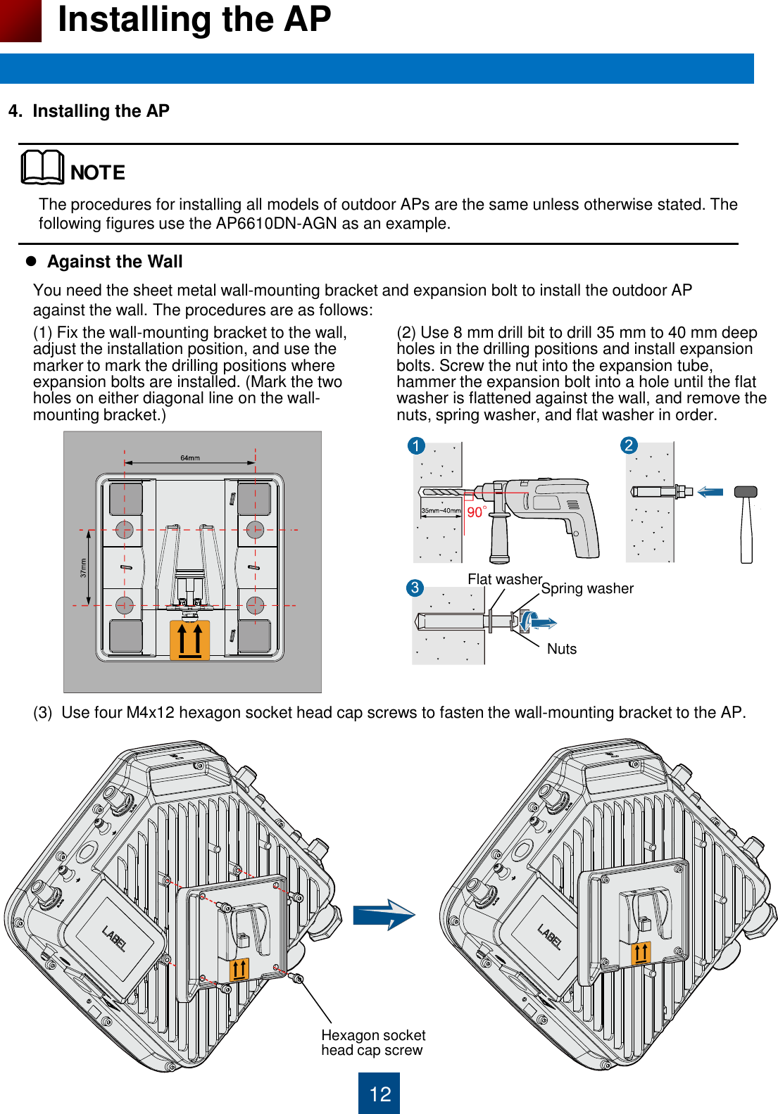
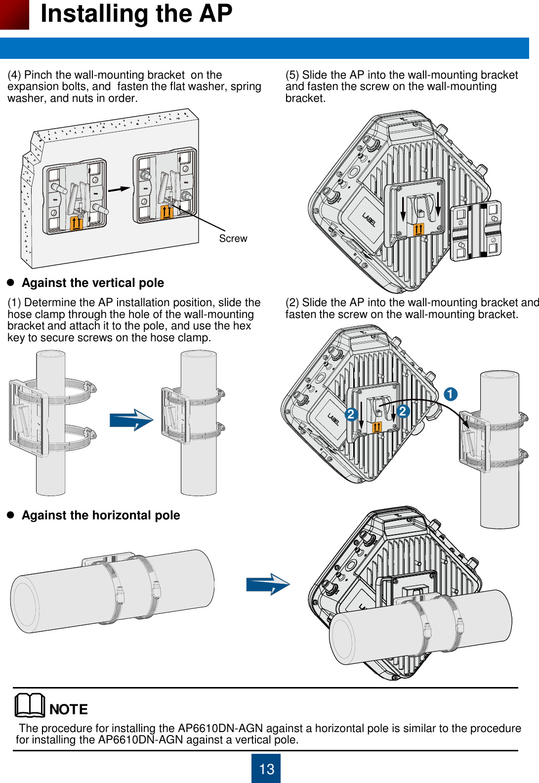
4.
19. AP6610DN-AGN-US_User Manual 1 Rev 1
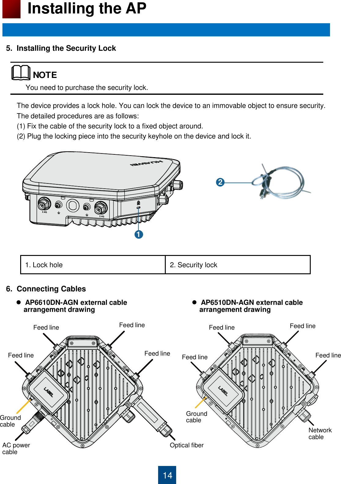
5.
13. AP6610DN-AGN-US_User Manual 1
6.
13. AP6610DN-AGN-US_User Manual 2
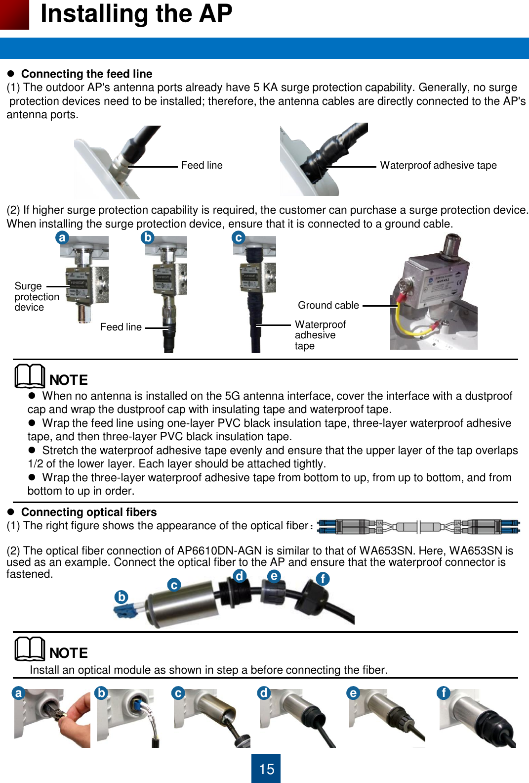
7.
13. AP6610DN-AGN-US_User Manual 3
13. AP6610DN-AGN-US_User Manual 1
Navigation menu
Upload a User Manual
Namespaces
Wiki Guide
HTML
PDF
Info
Views
User Manual
Discussion / Help
Navigation