Huawei Technologies AP6610DN-AGN Outdoor Wireless LAN Access Point User Manual 1
Huawei Technologies Co.,Ltd Outdoor Wireless LAN Access Point 1
Contents
13. AP6610DN-AGN-US_User Manual 1

AP Series Outdoor Wireless LAN Access Points
Quick Start Guide

Copyright © Huawei Technologies Co., Ltd. 2013. All rights reserved.
No part of this document may be reproduced or transmitted in any form or by any means without prior written
consent of Huawei Technologies Co., Ltd.
1
Trademarks and Permissions
and other Huawei trademarks are trademarks of Huawei Technologies Co., Ltd.
All other trademarks and trade names mentioned in this document are the property of their respective holders.
Notice
The purchased products, services and features are stipulated by the contract made between Huawei and the
customer. All or part of the products, services and features described in this document may not be within the
purchase scope or the usage scope. Unless otherwise specified in the contract, all statements, information,
and recommendations in this document are provided "AS IS" without warranties, guarantees or
representations of any kind, either express or implied.
The information in this document is subject to change without notice. Every effort has been made in the
preparation of this document to ensure accuracy of the contents, but all statements, information, and
recommendations in this document do not constitute the warranty of any kind, express or implied.
Huawei Technologies Co., Ltd.
Address: Huawei Industrial Base
Bantian, Longgang
Shenzhen 518129
People‟s Republic of China
Website: http://enterprise.huawei.com
Preface
2
This document describes the hardware configuration, installation preparation, installation method, installation
procedure, cable connection, and procedure for logging in to the outdoor APs.
The preface is organized as follows:
• Intended Audience
•Symbol Conventions
•Documentation Obtaining
•Technical Support
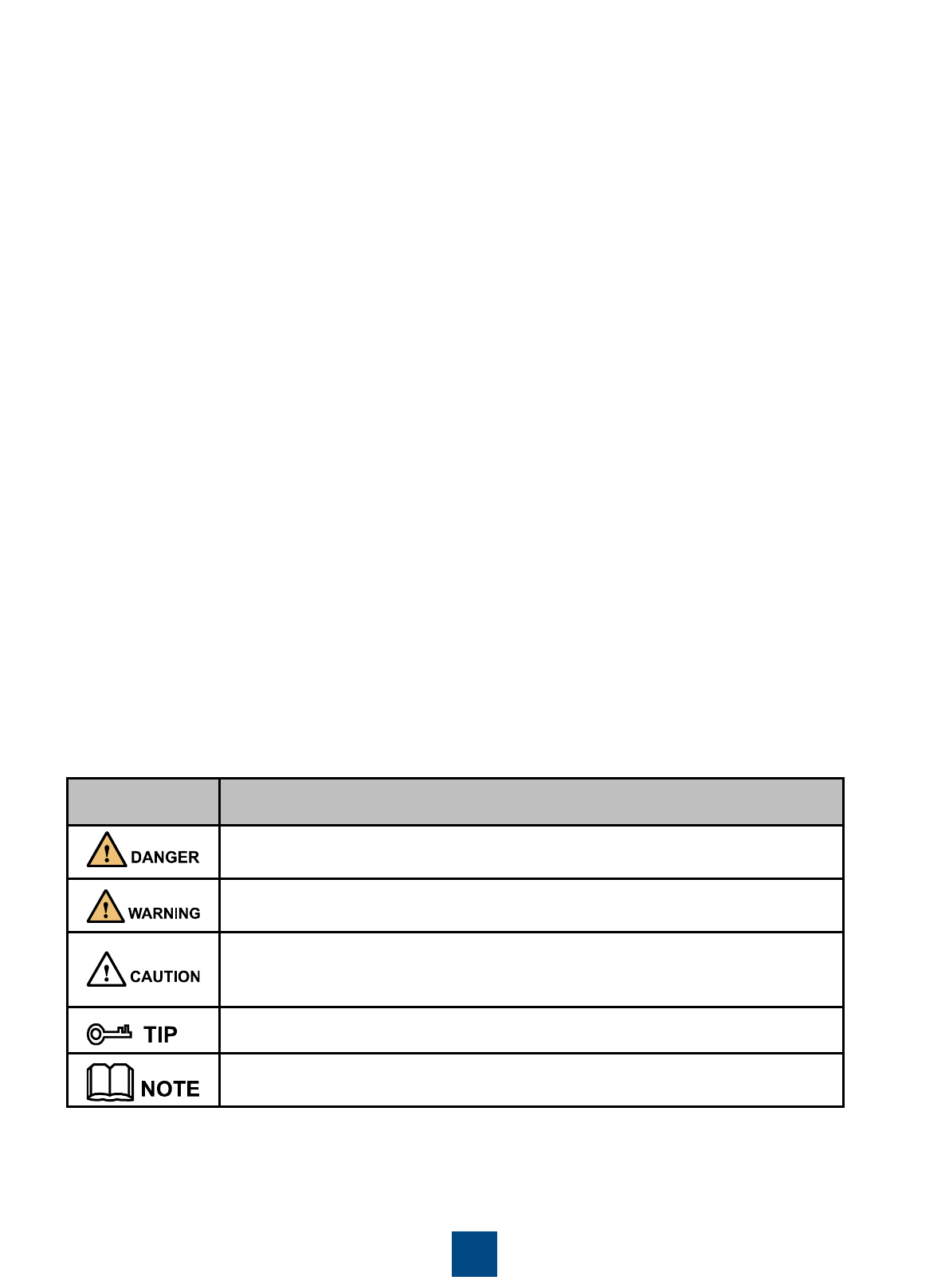
Symbol Conventions
The symbols that may be found in this document are defined as follows:
Intended Audience
This document is intended for:
•Hardware installation engineers
•Onsite maintenance engineers
•Network administrators configuring and maintaining the network
Symbol
Description
Indicates a hazard with a high level or medium level of risk which, if not
avoided, could result in death or serious injury.
Indicates a hazard with a low level of risk which, if not avoided, could result in
minor or moderate injury.
Indicates a potentially hazardous situation that, if not avoided, could result in
equipment damage, data loss, performance deterioration, or unanticipated
results.
Provides a tip that may help you solve a problem or save time.
Provides additional information to emphasize or supplement important points
of the main text.
Documentation Obtaining
You can visit http://enterprise.huawei.com to obtain the latest product documentations. Choose Support >
Product Support > Enterprise Networking > WLAN > AP, and then select the document of a specified
product.
You can select the document as required. For example, if you want to obtain AP6610DN-AGN documents,
select AP6610DN-AGN.
3
NOTE
Technical Support
If you have trouble in locating or rectifying faults during maintenance or troubleshooting by following
instructions in this document, contact the Huawei customer service center (CSC) for help.
You can also visit http://enterprise.huawei.com, click Contact Us in the lower area of the page, and select the
country to obtain contact information about Huawei local office.

Change History
Changes between document issues are cumulative. Therefore, the latest document issue contains all the
changes in previous issues.
Changes in Issue 02 (2013-01-30)
This version has the following updates:
The following information is added:
FCC compliance and sales regions of AP products
Change in Issue 01 (2012-10-31)
Initial commercial release.
4
5
Device Introduction
The Huawei AP series outdoor wireless LAN access point provides two models: AP6510DN-AGN,
AP6610DN-AGN. The outdoor AP supports 2.4GHz and 5 GHz frequency bands, and has enhanced
coverage performance and protection capabilities. It supports wireless bridging, complies with IEEE
802.11a/b/g/n, connects a large number of users, and works as a Fit AP. The outdoor AP features high
reliability, high security, simple network deployment, automatic AC discovery and configuration, and
real-time management and maintenance.
The APs are recommended for use in residential or commercial properties without wired resources. The
APs can be deployed at both ends of a commercial street or in the building opposite to a commercial
property. The APs must be equipped with external antennas to implement wireless signal coverage.
Different outdoor AP models are sold in different regions depending on whether the APs have passed
the FCC certification.
Table 1 FCC compliance and sales regions of AP products
Passed FCC
Certification
Product Model
Sales Region
No
AP6510DN-AGN
All regions except
Japan and
regions that
require FCC
certification
AP6610DN-AGN
Yes
AP6510DN-AGN-US
AP6510DN-AGN-US
Regions that
require FCC
certification
(except the U.S)
AP6510DN-AGN-USA
U.S
AP6610DN-AGN-US
AP6610DN-AGN-US
Regions that
require FCC
certification
(except the U.S)
AP6610DN-AGN-USA
U.S
The AP products sold in the U.S have a fixed country code US, and the country code change function
is disabled.
The AP6510DN-AGN, AP6510DN-AGN-US, and AP6510DN-AGN-USA have the same specifications
and are installed in the same way. This document collectively calls the three models AP6510DN-AGN.
The AP6610DN-AGN, AP6610DN-AGN-US, and AP6610DN-AGN-USA have the same specifications
and are installed in the same way. This document collectively calls the three models AP6610DN-AGN.
NOTE
6
Device Introduction
Table 2 lists the dimensions and weights of outdoor APs.
Table 2 Dimensions and weight
Model
Dimensions
Weight
AP6510DN-AGN
255mm×255mm×83mm(W×D×H)
2.2kg
AP6610DN-AGN
255mm×255mm×83mm(W×D×H)
2.65kg
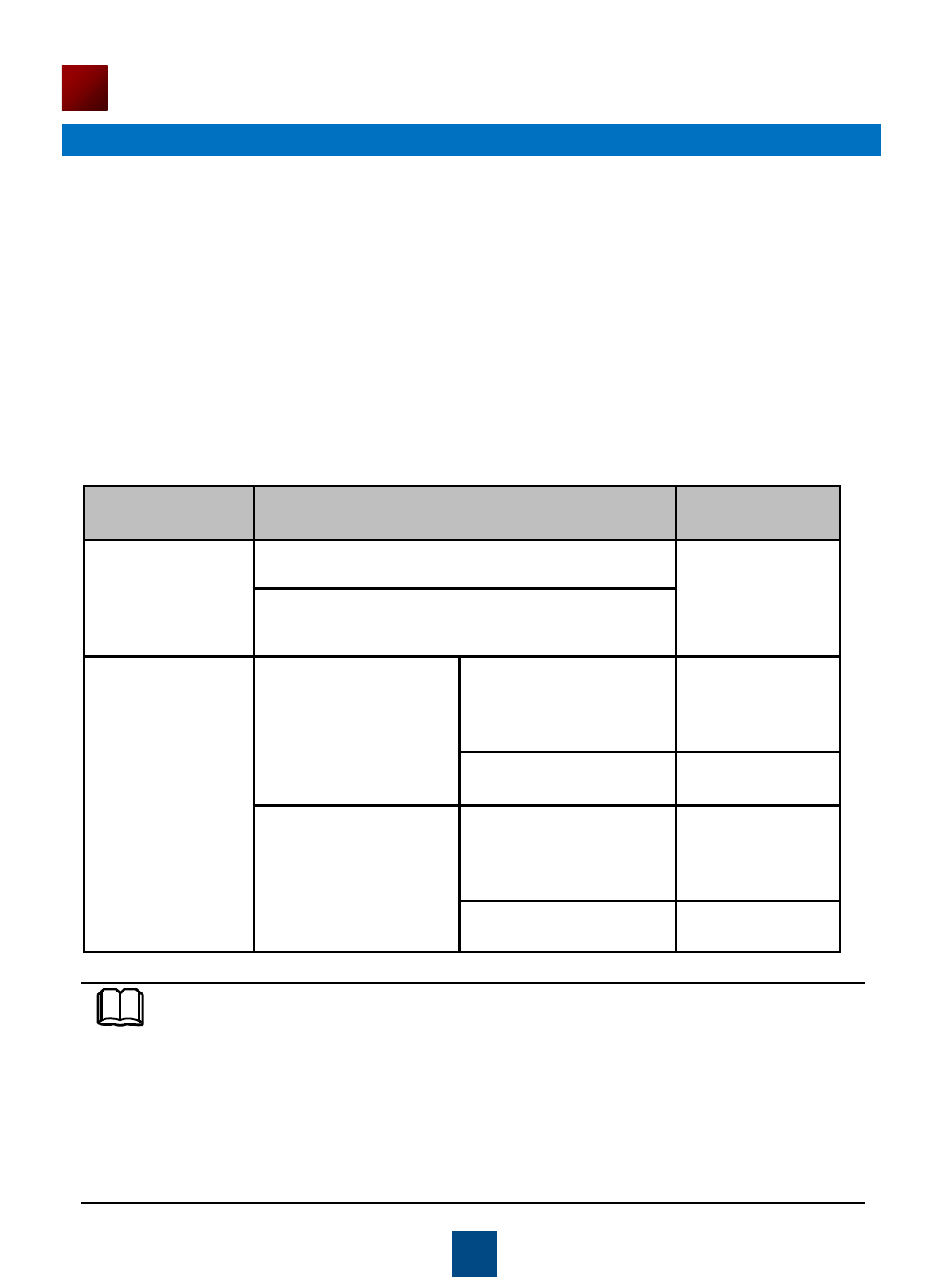
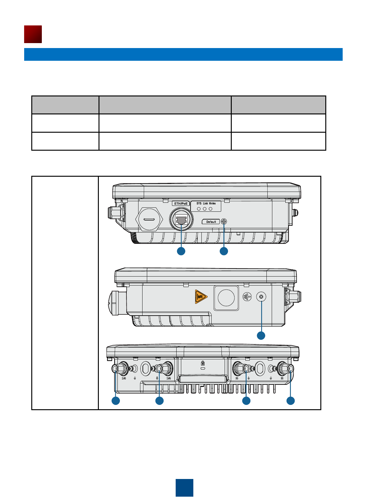
Table 3 Interfaces on outdoor APs
AP6510DN-AGN
5 5 6 6
1 2
7
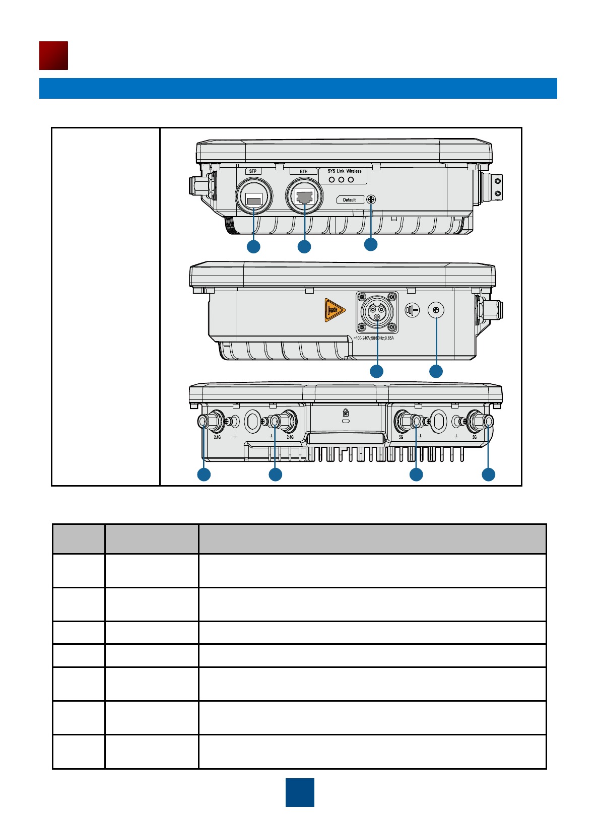
AP6610DN-AGN
7
Device Introduction
No.
Name
Description
1
ETH port
(ETH/PoE port)
Connected to a switch or PD.
2
Default
Press and hold down the Reset button for 3 seconds to restore the
factory settings and restart the AP.
3
SFP port
Connected to fiber. An optical module is required.
4
AC power port
Connected to an AC power module.
5
2.4 GHz
antenna port
A port connected to the 2.4 GHz antenna.
6
5 GHz
antenna port
A port connected to the 5 GHz antenna.
7
Ground screw
Connect the ground cable to the AP with a ground screw.
Table 3 Interfaces on outdoor APs
Table 4 Interfaces on outdoor APs
1 2
5 5 6 6
3
4 7
8
Installation Preparations
1. Safety Precautions
2. Installation Environment Check
Before installation, verify that the device runs in a favorable environment.
The table lists requirements on the environment that a device works in, including the temperature,
humidity, altitude, and pressure.
Table 5 Requirements on the environment
Only the qualified personnel are permitted to install and remove the device and its accessories.
Before installation and operation, read the safety precautions carefully.
Take proper measures to prevent injuries and device damage.
Place the device in a dry and flat position away from any liquid and prevent the device from
slipping.
Keep the device clean.
Do not put the device and tools in the aisles.
Item
Range
Operating temperature
AP6510DN-AGN: -40℃~60℃
AP6610DN-AGN: -40℃~60℃
Storage temperature
AP6510DN-AGN: -40℃~70℃
AP6610DN-AGN: -40℃~70℃
Relative humidity
0% to 100%
Altitude
-60 m to +4000 m
Pressure
70 kPa to 106 kPa
WARNING
9
Installation Preparations
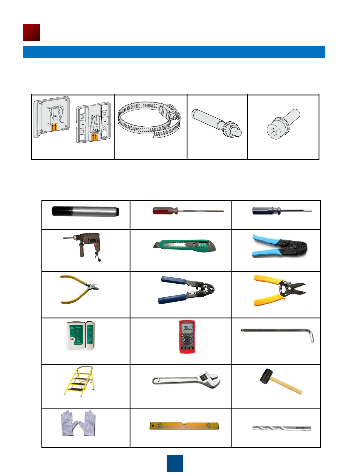
3. Device Accessories
The following accessories are delivered together with outdoor APs:
4. Installation Tools
To install outdoor APs, prepare the following tools:
Phillips screwdriver Flat-head screwdriver
Utility knife
Wire stripper
Network cable tester Multimeter
Adjustable wrench
Maker
RJ45 crimping tool Diagonal pliers
Ladder
COAX crimping tool
Hammer drill
Hammer
ESD gloves Level 8mm drill bit
M4x12 hexagon
socket head cap screw
Installation suite Hose clamp Expansion bolt
Hex key
No.
Item
Quantity
Unit
1
AP device
1
PCS
2
Installation suite
1
PCS
3
Network port connector
1
PCS
4
M4x12 hexagon socket head cap screw
4
PCS
5
Expansion bolt
2
PCS
6
Hose clamp
2
PCS
7
Fiber wrench
1
PCS
8
OT terminals
2
PCS
9
Quick Start
1
PCS
10
Installing the AP
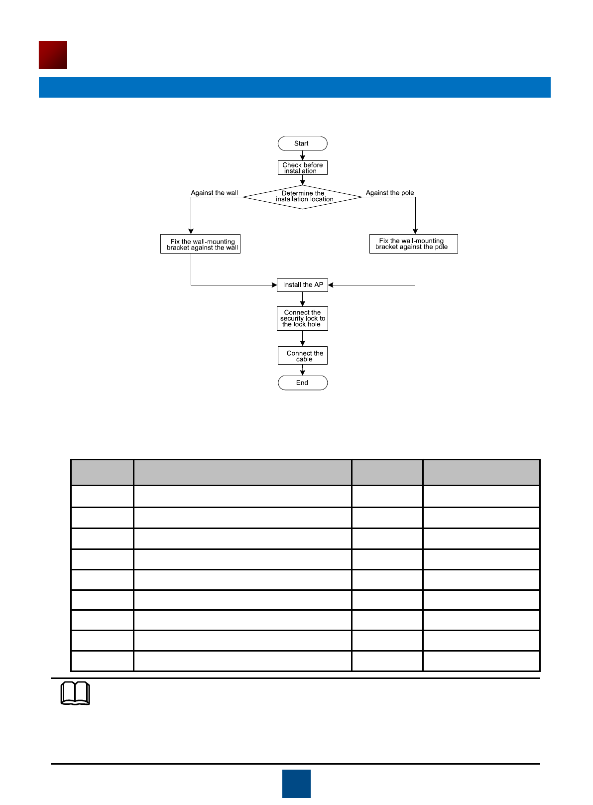
1. Installation Flowchart
Figure 1 Flowchart for installing an AP
2. Checking Before Installation
Unpack the package. Ensure that all the items listed in the packing list are included in the carton. If
any item is missing, contact the supplier.
Table 6 Packing list
NOTE
Before unpacking the carton, ensure that the packing carton is intact and that the carton is
not severely damaged or soaked. Stop unpacking if the packing carton is rusted or socked.
Then, investigate causes and give a feedback to the vendor.
Optical fiber tubes are only contained in the AP6610DN-AGN packing carton.
11
Installing the AP
3. Determining the Installation Position
When determining the AP installation position, comply with the following rules:
Install the AP free from high temperature, dust, toxic gases, flammable or explosive materials,
unstable voltage, or electromagnetic interferences, such as radar stations, launch pads, or
transformer substations. The AP should also be away from great vibrations and strong noises.
Install the AP away from water, drippings, and dews.
Install the AP in a hidden position in order not to disturb people.
Consider the communication network planning and the technical requirements of the equipment in
the project design. In addition, hydrographic, geological, seismic, power supply, and transportation
factors must be considered.
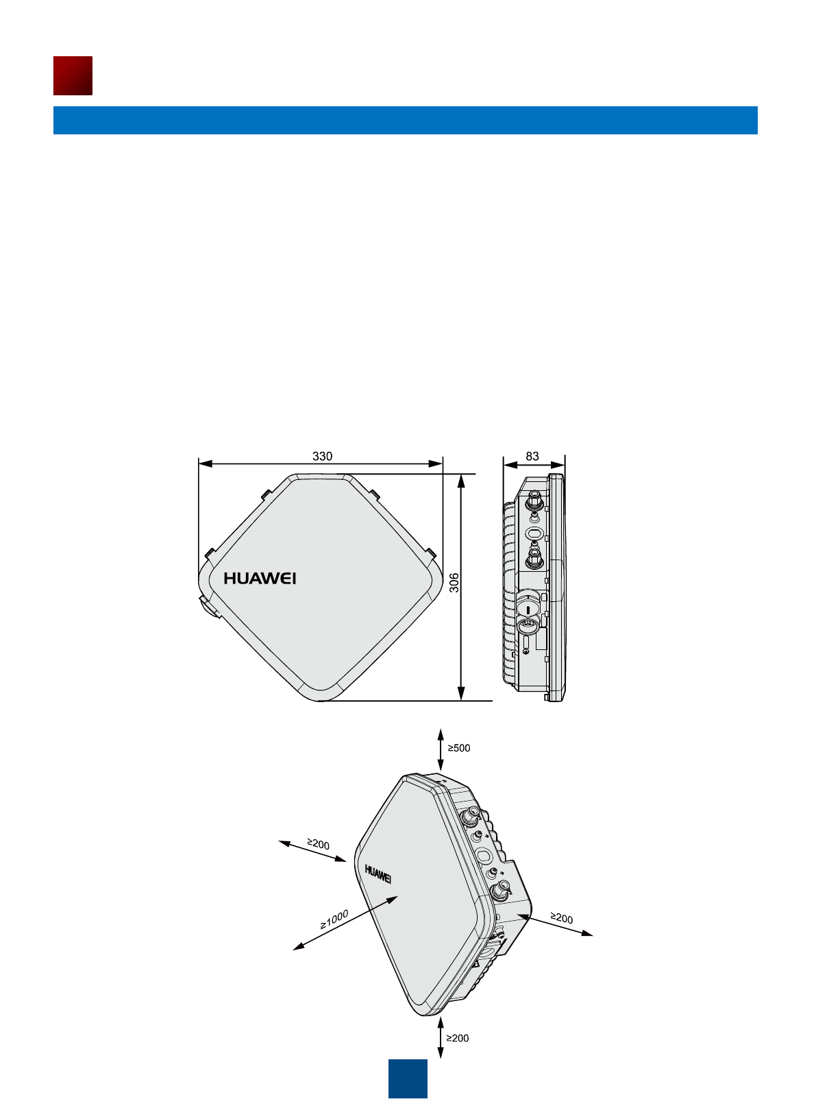
Outdoor APs can be installed on poles or wall. The pole diameter is 48 mm to 114 mm and the
thickness must be at least 2.5 mm. The AP must be installed by the installation personnel in the
position determined by site survey. The recommended AP installation space is as follows:
Figure 2 AP dimensions (unit: mm)
Figure 3 Recommended AP installation space (unit: mm)
12
Installing the AP
4. Installing the AP
Against the Wall
The procedures for installing all models of outdoor APs are the same unless otherwise stated. The
following figures use the AP6610DN-AGN as an example.
(1) Fix the wall-mounting bracket to the wall,
adjust the installation position, and use the
marker to mark the drilling positions where
expansion bolts are installed. (Mark the two
holes on either diagonal line on the wall-
mounting bracket.)
(2) Use 8 mm drill bit to drill 35 mm to 40 mm deep
holes in the drilling positions and install expansion
bolts. Screw the nut into the expansion tube,
hammer the expansion bolt into a hole until the flat
washer is flattened against the wall, and remove the
nuts, spring washer, and flat washer in order.
(3) Use four M4x12 hexagon socket head cap screws to fasten the wall-mounting bracket to the AP.
NOTE
You need the sheet metal wall-mounting bracket and expansion bolt to install the outdoor AP
against the wall. The procedures are as follows:
Flat washer
Spring washer
Nuts
Hexagon socket
head cap screw
13
Installing the AP
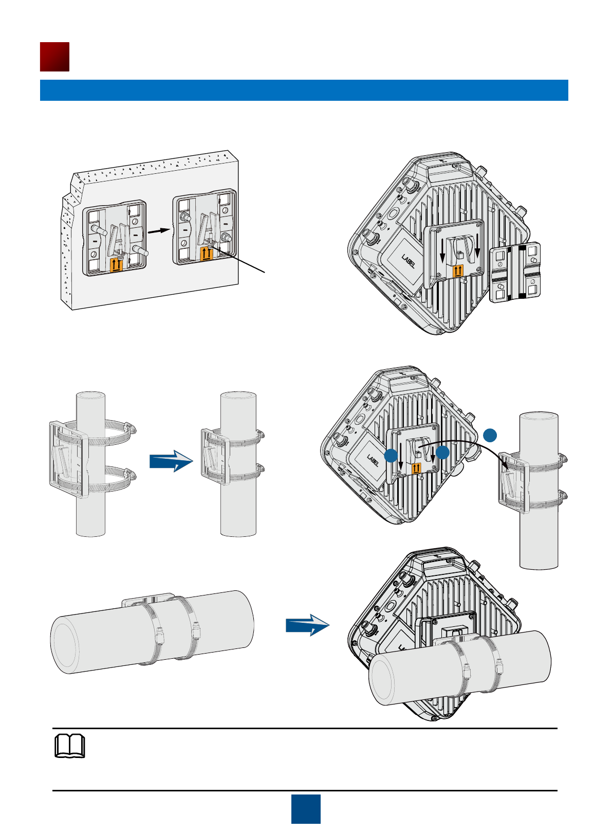
The procedure for installing the AP6610DN-AGN against a horizontal pole is similar to the procedure
for installing the AP6610DN-AGN against a vertical pole.
(4) Pinch the wall-mounting bracket on the
expansion bolts, and fasten the flat washer, spring
washer, and nuts in order.
(5) Slide the AP into the wall-mounting bracket
and fasten the screw on the wall-mounting
bracket.
Against the vertical pole
(1) Determine the AP installation position, slide the
hose clamp through the hole of the wall-mounting
bracket and attach it to the pole, and use the hex
key to secure screws on the hose clamp.
(2) Slide the AP into the wall-mounting bracket and
fasten the screw on the wall-mounting bracket.
1
2 2
Against the horizontal pole
NOTE
Screw
6. Connecting Cables
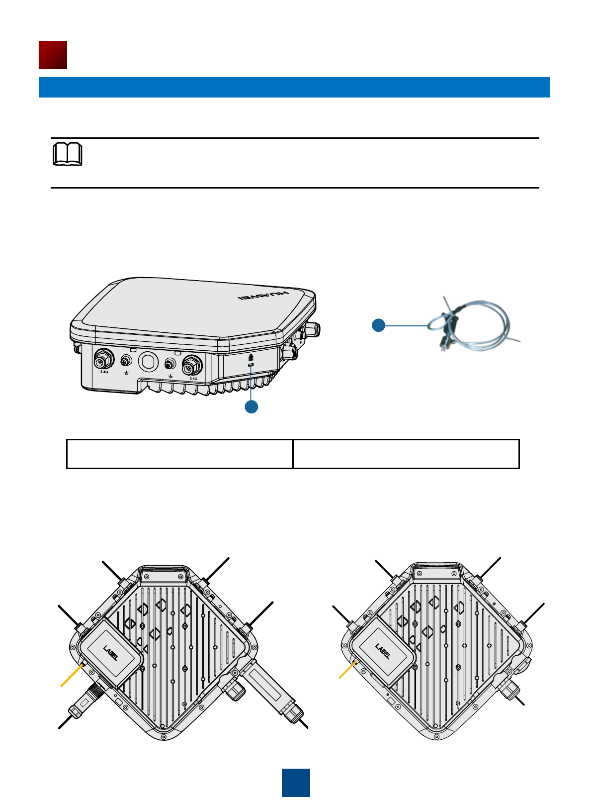
5. Installing the Security Lock
14
Installing the AP
You need to purchase the security lock.
1. Lock hole
2. Security lock
The device provides a lock hole. You can lock the device to an immovable object to ensure security.
The detailed procedures are as follows:
(1) Fix the cable of the security lock to a fixed object around.
(2) Plug the locking piece into the security keyhole on the device and lock it.
AP6610DN-AGN external cable
arrangement drawing
NOTE
1
2
Feed line
Feed line
Feed line
Feed line Feed line
Feed line Feed line
Feed line
Network
cable
Ground
cable
Ground
cable
AC power
cable Optical fiber
AP6510DN-AGN external cable
arrangement drawing
15
Installing the AP
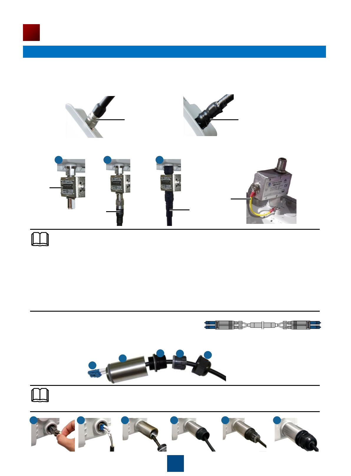
Connecting the feed line
(1) The outdoor AP's antenna ports already have 5 KA surge protection capability. Generally, no surge
protection devices need to be installed; therefore, the antenna cables are directly connected to the AP's
antenna ports.
(2) If higher surge protection capability is required, the customer can purchase a surge protection device.
When installing the surge protection device, ensure that it is connected to a ground cable.
Feed line Waterproof adhesive tape
Surge
protection
device
Feed line Waterproof
adhesive
tape
Ground cable
a b c
NOTE
When no antenna is installed on the 5G antenna interface, cover the interface with a dustproof
cap and wrap the dustproof cap with insulating tape and waterproof tape.
Wrap the feed line using one-layer PVC black insulation tape, three-layer waterproof adhesive
tape, and then three-layer PVC black insulation tape.
Stretch the waterproof adhesive tape evenly and ensure that the upper layer of the tap overlaps
1/2 of the lower layer. Each layer should be attached tightly.
Wrap the three-layer waterproof adhesive tape from bottom to up, from up to bottom, and from
bottom to up in order.
Connecting optical fibers
(1) The right figure shows the appearance of the optical fiber:
(2) The optical fiber connection of AP6610DN-AGN is similar to that of WA653SN. Here, WA653SN is
used as an example. Connect the optical fiber to the AP and ensure that the waterproof connector is
fastened.
b c d e f
NOTE
Install an optical module as shown in step a before connecting the fiber.
a b c d e f
16
Installing the AP
The thread must be secured properly; otherwise, optical fibers may be damaged. When removing
optical fibers, remove the waterproof PG connector, and then remove the optical fiber connected to
the AP. When removing the waterproof PG connector, use the ejector lever to clutch the optical fiber
tube. This prevents the optical fiber tube from rotating with the waterproof PG connector and protects
optical fibers.
Connecting optical fibers
(1) Make an AC power cable onsite, cut the cable of proper length. Make a cable according to figure 4.
L/N/PE pin arrangement must be correct.
(2) When connecting the AC power cable to the AP, align the socket to the red point of the connector,
and insert the waterproof connector. When a crack sound is heard, the AC power cable is installed
properly. When removing the AC power cable, press the component with the red point. You do not
need loosen the screw. (figure 5)
Figure 4 Figure 5
Making AC Power Cables Onsite
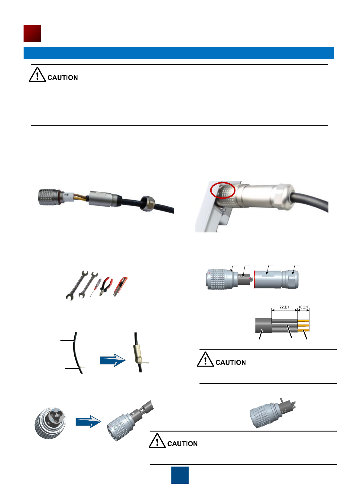
a Preparation
(1) The required tools are as follows: open-end (2) The following table shows the connector
wrench (22mmX24mm), open-end wrench components.
(22mmX24mm), Phillips screwdriver (0#X50mm),
diagonal pliers, and utility knife.
b Connection
(1) Use cable ties to fasten the cable, remove the (2) Strip the cable.
socket and nut together, and then lead the cable through
the socket and nut.
(3) Install the core wires in the L, N and PE holes. (4) Tighten the screws in the three holes using a
Phillips screwdriver.
Shell Screw Socket Nut
Wiring
terminal
Cable tie
Cable Core wire Conductor
Be careful when striping the cable, please don't
damage the Core wire and the Conductor.
After the screws are tightened, check that the cable is securely
installed by evenly pulling the cable with a 10 kg force.
17
Installing the AP
(5) Tighten the Socket and Shell using hand until you (6) Pre-tighten the nut and socket, and then further
can„t see the red color band. tighten the nut using a wrench with a torque of
more than 1.2N·m.
c Verification
Use a multimeter to test the reliability of the cable
components.
d Protection
The device is placed outdoors, warp up the connector using three layers of PVC insulation tapes to prevent
it from being damaged, as shown in the following figure.
Red color band Nut Wrench specifications:22
Before tightened the socket and shell, the cable
can't be tightened by the nut. Please be careful not to damage the surface coating
of parts when tightening the nut and socket.
Connector jacks can't be short-circuited.
Connections between the metal shell and the
connector jacks can't be short-circuited.
Cable core wires are connected properly to the
corresponding connector jacks.
NOTE
Each radio connector must be wrapped by three layers of waterproof tape and three layers of
insulating tape.
Wrap the tape from bottom to top, from top to bottom, and then from bottom to top. Cut the tape after
wrapping three layers of tape on the connector.
Wrap each layer of tape tightly and ensure that each layer covers more than 50% of the layer below it.
Before wrapping the waterproof tape, stretch the tape evenly until the tape turns 1/2 as wide as before.
After wrapping the tape, bundle cable ties at both ends of the insulating tape to prevent aging of the
tape.
Connecting the ground cable
Cut the cable of proper length, and select 6-M4 OT terminal for the AP and 6-M6 OT terminal for the
ground bar.
Connecting the
ground bar
18
Installing the AP
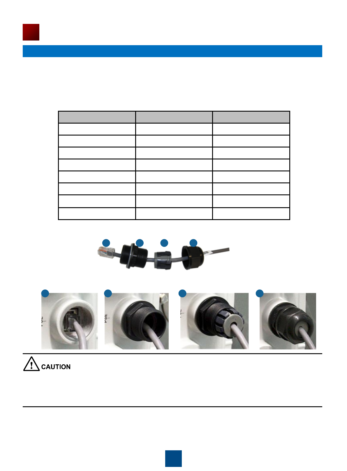
Connecting network cable
(1) Use a shield straight-through cable. Cut the cable of proper length based on the distance between the
AP and the PSE device, peel the insulation on both ends of the network cable, and crimp the wires to RJ45
connectors.
(2) Make a network cable onsite according to the following pin assignment. Otherwise, the communication
quality is affected even if devices can be connected.
(3) Put the network cable through the hole on the waterproof PG connector.
(4) Connect the RJ45 connector to the AP and secure the waterproof PG connector, as shown in figures
b, c, and d.
X1 Pin
Wire Color
X2 Pin
1
White and orange
1
2
Orange
2
3
White and green
3
4
Blue
4
5
White and blue
5
6
Green
6
7
White and brown
7
8
Brown
8
Table 7 Pin assignment
a b c d
a b c d
The network cables used are shield straight-through cables.
Ensure that the RJ45 connector is correctly connected to the AP. Otherwise, the network cable may be
damaged. Before removing the network cable, remove the waterproof PG connector, and then remove the
RJ45 connector from the AP.
Directional
outdoor antenna
19
Installing the AP
Installing outdoor antennas
Two types of outdoor antennas are available: directional outdoor antenna and omnidirectional outdoor
antenna. Omnidirectional antennas can be directly installed on APs. The following are the procedures for
installing directional and omnidirectional outdoor antennas.
1. Perform the following steps to install a directional outdoor antenna:
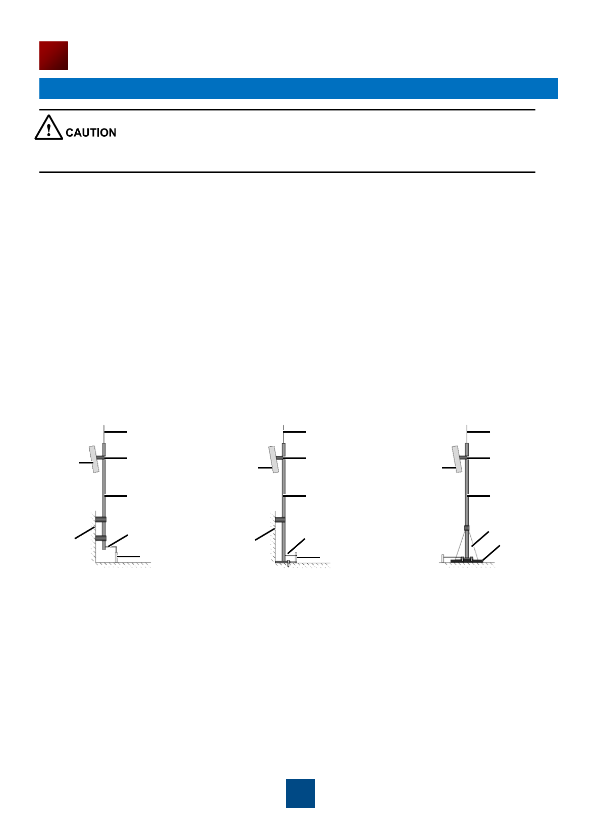
(1) Weld the lightning rod on the top of the antenna pole.
(2) Install the antenna pole on a parapet or concrete bed on the roof of the building.
(3) Use a 40 mm x 4 mm flat steel to connect the antenna pole to an earth mat.
(4) Secure the directional outdoor antenna on the pole with an antenna support.
Keep the pole vertical with the ground during the installation. (See the figure below for how a directional
outdoor antenna is installed on a pole.)
If roof of the building is surrounded by parapets of no less than 1.2 m high, fix the pole on a parapet with
expansion screws, and then fix the directional outdoor antenna on the pole with an antenna support.
If roof of the building is surrounded by parapets of less than 1.2 m high, fix the pole on a parapet and on
the ground with expansion screws, and then fix the directional outdoor antenna on the pole with an antenna
support.
If there is no parapets around the roof, fix the pole on the ground or a concrete bed with expansion
screws and steel wires, and then fix the directional outdoor antenna on the pole with an antenna support.
Lightning rod
Flat steel
Connect to earth mat
Parapet
Height of parapet > 1200 mm Height of parapet <1200 mm No parapet
Antenna support
Antenna pole
Directional
outdoor antenna
Lightning rod
Flat steel
Connect to earth mat
Parapet
Antenna support
Antenna pole
Directional
outdoor antenna
Lightning rod
Antenna support
Antenna pole
Steel wire
Concrete bed
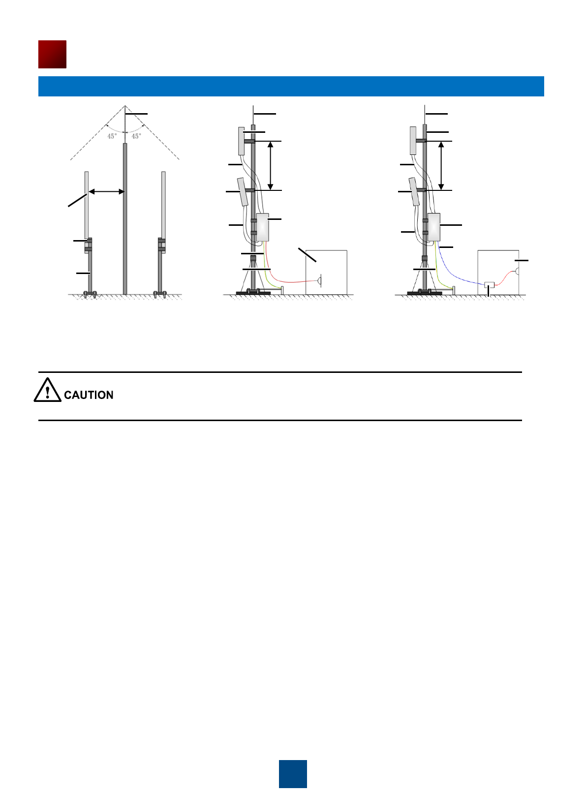
2. Perform the following steps to install a omnidirectional outdoor antenna:
Pay attention to the following points when installing an omnidirectional antenna:
(1) An omnidirectional outdoor must be installed on a pole with a diameter of 30 mm to 50 mm and the
thickness must be at least 2.5 mm. A 50 mm diameter pole made of round steel is usually used.
(2) The top of pole must be aligned with the hose clamp at the bottom of the antenna, as show in the figure 6.
(3) After the installation is complete, the antenna must high enough to provide sufficient signal coverage, and
the top of the antenna must be within the 45o protection angle of the lighting rod.
(4) Do no weld a lightning rod directly on the antenna pole (because there should not be metal subjects
within 1 m around an omnidirectional antenna). Instead, install an independent lightning rod between two
omnidirectional antenna poles. Adjust the height of the lightning rod to ensure that the omnidirectional
antennas are covered in the protection angle.
Only qualified professional personnel can install antennas. An AP can only be equipped with the
antennas delivered with it.
20
Installing the AP
Lightning rod
5GHz antenna
Lightning rod
Protection
angle
>1.0m
Hose
clamp
Antenna
pole
RF cable
2.4GHz
antenna
RF cable AP6610DN-AGN
Ground wire
Power line
AC Power
100V~240V
Figure 6
AP6510DN-AGN
>0.5m >0.5m
Ground wire
Ultra-5 cable
PoE adapter
Omnidirectional
outdoor antenna
Lightning rod
5GHz antenna
RF cable
2.4GHz
antenna
RF cable
AC Power
100V~240V
Pressing the Reset Button
The Reset button on an outdoor AP is protected by a waterproof screw. Before pressing the Reset button,
remove the waterproof screw.
Keep the screw properly and install it again after pressing the Reset button.
Requirements for laying Out Cables
Requirements for laying out ground cables
(1) All ground cables must be connected to a ground bar.
(2) The ground cable cannot be led in aerially, but buried in the earth or arranged indoor.
(3) Both ends of the external conductor of the coaxial cable and those of the insulation of the shielded cable
should have good electric contact with the metal shell of the equipment they connect to.
(4) Ground cables must be separated from signal cables to reduce interference between them.
(5) Do not add any switch or fuse on the ground cable.
(6) Do not use another device for an electrical connection with the ground cable.
(7) All metal components in the shell must be securely connected to the ground cable.
Information
Type
SYS
Link
Wireless
Description
Startup
status
Steady
green
NA
NA
The device is being started.
Blinking
green
NA
NA
The system is working properly.
Steady
red
NA
NA
The system fails to load the DRAM or system
software.
Running and
connection
0.5Hz
Off
Off
The system is working properly. However, the
Ethernet is not connected. Radios are disabled
and no user is connected to the AP.
Blinking
green
The system is working properly, but the Ethernet
is not connected. The AP has wireless users
connected to the 2.4 GHz band and is
transmitting data. The indicator blinks more
quickly when more packets are being transmitted.
Blinking
yellow
The system is working properly, but the Ethernet
is not connected. The AP has wireless users
connected to the 5 GHz band and is transmitting
data. The indicator blinks more quickly when
more packets are being transmitted.
Blinking
green and
yellow
alternately
The system is working properly, but the Ethernet
is not connected. The AP has wireless users
connected to the 2.4 GHz and 5 GHz bands and
is transmitting data.
0.5Hz
Steady or
Blinking
green
Off
The system is working properly, the Ethernet is
connected, and radios are disabled. The indicator
blinks more quickly when more data is being
transmitted.
Blinking
green
The system is working properly, and the Ethernet
is connected. The AP has wireless users
connected to the 2.4 GHz band and is
transmitting data. The indicator blinks more
quickly when more packets are being transmitted.
Blinking
yellow
The system is working properly, and the Ethernet
is connected. The AP has wireless users
connected to the 5 GHz band and is transmitting
data. The indicator blinks more quickly when
more packets are being transmitted.
Blinking
green and
yellow
alternately
The AP has wireless users connected to the 2.4
GHz and 5 GHz bands and is transmitting data.
The indicator blinks more quickly when more
packets are being transmitted.
21
Power-on
Table 8 Indicator status of the AP6510DN-AGN and AP6610DN-AGN
Power on the AP and check the indicator status to determine the system running status.
NOTE
The AP6510DN-AGN supports the PoE function that complies with 802.3at.
State
Blinking Frequency
Meaning
Blinking very
fast
10 Hz
The AP is transmitting or receiving data normally, and the
receive signal strength is high.
Blinking fast
2 Hz
The AP is transmitting or receiving data normally, and the
receive signal strength is medium.
Blinking slowly
0.5 Hz
The AP is transmitting or receiving data normally, and the
receive signal strength is low.
Off
0 Hz
The AP is not transmitting or receiving data.
22
Power-on
If an AP is deployed on a WDS network, you can check the Wireless indicator on the AP to determine
whether the AP transmits and receives wireless data normally when it is establishing a WDS link with
another AP. The Wireless indicator has four possible states, as described in the following table.
Table 9 Wireless indicator status
When the WDS function is enabled on an AP, the blinking frequency of its Wireless indicator indicates
the receive signal strength by default. You can run the wifi-light { signal-strength | traffic } command
on the A to make the blinking frequency of its Wireless indicator indicate receive signal strength or
service traffic rate.
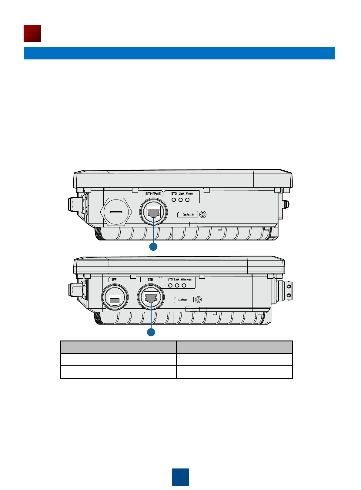
1. Logging In to the AP Using Telnet
This section describes how to log in to the AP using Telnet. After logging in to the AP, you can
configure the AP using commands.
Procedure
Step 1 Connect a PC to the uplink port of the AP with a network cable. Figure 7 shows the location
of the AP's uplink port.
Figure 7 Location of the AP's uplink port
Step 2 Configure a static IP address for the PC. The IP address must be on the network segment
192.168.0.1/24 (The IP address should not be same as the AP's default IP address
192.168.0.1.) and the subnet mask is 255.255.255.0.
After the configuration is complete, run the ping 192.168.0.1 command on the PC to check
whether the PC can be pinged. If the ping operation succeeds, the connection is set up
successfully. If the ping operation fails, the connection fails to be set up. Check whether the
network cable works properly.
Step 3 Access the command line window on the PC. For example, if the PC runs Windows XP,
choose Start > Run and enter cmd in the displayed dialog box.
23
Logging In to the AP
After an AP is powered on, you can log in to the AP using the following methods.
1. Logging In to the AP Using Telnet
1
2
No.
Port
1
ETH/PoE
2
ETH

Step 4 Run the telnet 192.168.0.1 command to log in to the AP.
Step 5 Enter the default user name and password admin. If the user view is displayed, you have
logged in successfully.
24
Logging In to the AP
If you logged in to the AP from an AC or a switch, press Ctrl+T to return to the AC or switch view.
This operation does not affect the AP operation.
If you logged in to the AP from a PC, directly close the Telnet window. This operation does not
affect the AP operation.
Run the exit command to exit from the Telnet window. When the system fails to exit from the Telnet
window:
NOTE
49
Appendix
1. Declaration on Hazardous Substances in Electronic Information Products
2. Qualification Card
Parts
Hazardous Substances
Pb
Hg
Cd
Cr6+
PBB
PBDE
Mechanical part
O
O
O
O
O
O
Board/circuit module
O
O
O
O
O
O
Signal cable
O
O
O
O
O
O
Cable connector
O
O
O
O
O
O
Power adapter
O
O
O
O
O
O
Auxiliary equipment
O
O
O
O
O
O
O: Indicates that the concentration of the hazardous substance contained in all the homogeneous
materials of this part is below the limit requirement of the SJ/T 11363-2006 standard.
X: Indicates that the Concentration of the hazardous substance contained in all the homogeneous
materials of this part is above the limit requirement.
PASS
Qualification Card
51
Appendix
3. Warranty Card
Warranty Card
Thank you for choosing HUAWEI Technologies Co., Ltd-a leading telecom solution provider. To get better services,
please read this warranty card carefully, fill in the required information and preserve this card in good condition.
Dealer's Seal:
Limited Warranty
Subject to the exclusions contained below, Huawei Technologies Co., Ltd. (hereinafter referred to as Huawei) warrants
its access terminals (“Products”) to be free from defects in materials and workmanship under normal consumer usage
for one year from the date of purchase of the product ("Warranty period"). During the warranty period, a Huawei
authorized service partner shall remedy defects in materials and workmanship free of charge.
Special Notice:
1. The warranty card shall be applicable only after being stamped by the dealer.
2. The warranty card must be preserved in good condition and free of any scratch or alteration.
3. To claim such service for defects that are not included in the following exclusion terms, the warranty card and
the invoice that records the product serial number shall be presented to a Huawei authorized service partner.
Exclusions:
In any of the following cases, the warranty card becomes unenforceable or inapplicable without prior notice:
1. The defects are caused by improper handling in transportation and assembly.
2. The defects are caused by the fact that the product is dismantled or altered by anyone that is not from a
Huawei authorized service partner.
3. The defects are caused by the fact that the product is used in a harsh environment that is not suitable for the
operation of the product.
4. The defects are caused by any force majeure including but not limited to fire, earthquake, lightning and tsunami.
5. The defects are caused by the fact that the product is used or handled improperly, roughly or not as instructed in
the applicable User Guide.
6. The normal wear and tear, including but not limited to the normal wear and tear of the shell and the power module,
shall not be covered by the limited warranty.
7. The warranty card is altered or illegible, or the product serial number recorded on the warranty card is inconsistent
with the actual one imprinted or labeled on the product.
In any case that is not covered by this limited warranty or should the warranty expire, Huawei shall charge for the
service(s) claimed for the products if the product is still remediable.
Huawei preserves the right for interpretation of this limited warranty.
Huawei Technologies Co., Ltd.
Huawei Industrial Base, Bantian, Longgang,
Shenzhen 518129, People's Republic of China
http://enterprise.huawei.com
Your Name
Address/Postal Code
Telephone
Product Type
Product Serial Number.
Purchase Date.
Invoice Number.
Dealer's Name
Dealer's Address/Telephone
Preserve well. No reissue