Huawei Technologies AR1220WIFI Access Router User Manual Hardware Description
Huawei Technologies Co.,Ltd Access Router Hardware Description
Contents
- 1. User Manual
- 2. User manual I
- 3. User manual II
- 4. User manual III
User manual II

Huawei AR1200-S&2200-S Series Enterprise
Routers
V200R001C01
Hardware Description
Issue 03
Date 2012-04-20
HUAWEI TECHNOLOGIES CO., LTD.

Copyright © Huawei Technologies Co., Ltd. 2012. All rights reserved.
No part of this document may be reproduced or transmitted in any form or by any means without prior written
consent of Huawei Technologies Co., Ltd.
Trademarks and Permissions
and other Huawei trademarks are trademarks of Huawei Technologies Co., Ltd.
All other trademarks and trade names mentioned in this document are the property of their respective holders.
Notice
The purchased products, services and features are stipulated by the contract made between Huawei and the
customer. All or part of the products, services and features described in this document may not be within the
purchase scope or the usage scope. Unless otherwise specified in the contract, all statements, information,
and recommendations in this document are provided "AS IS" without warranties, guarantees or representations
of any kind, either express or implied.
The information in this document is subject to change without notice. Every effort has been made in the
preparation of this document to ensure accuracy of the contents, but all statements, information, and
recommendations in this document do not constitute the warranty of any kind, express or implied.
Huawei Technologies Co., Ltd.
Address: Huawei Industrial Base
Bantian, Longgang
Shenzhen 518129
People's Republic of China
Website: http://www.huawei.com
Email: support@huawei.com
Issue 03 (2012-04-20) Huawei Proprietary and Confidential
Copyright © Huawei Technologies Co., Ltd.
i
About This Document
Intended Audience
This document provides an overall description of the AR routers, details about each chassis and
board, cables available to the device, and lists of components.
This document is intended for:
lNetwork planning engineers
lHardware installation engineers
lCommissioning engineers
lOn-site maintenance engineers
lSystem maintenance engineers
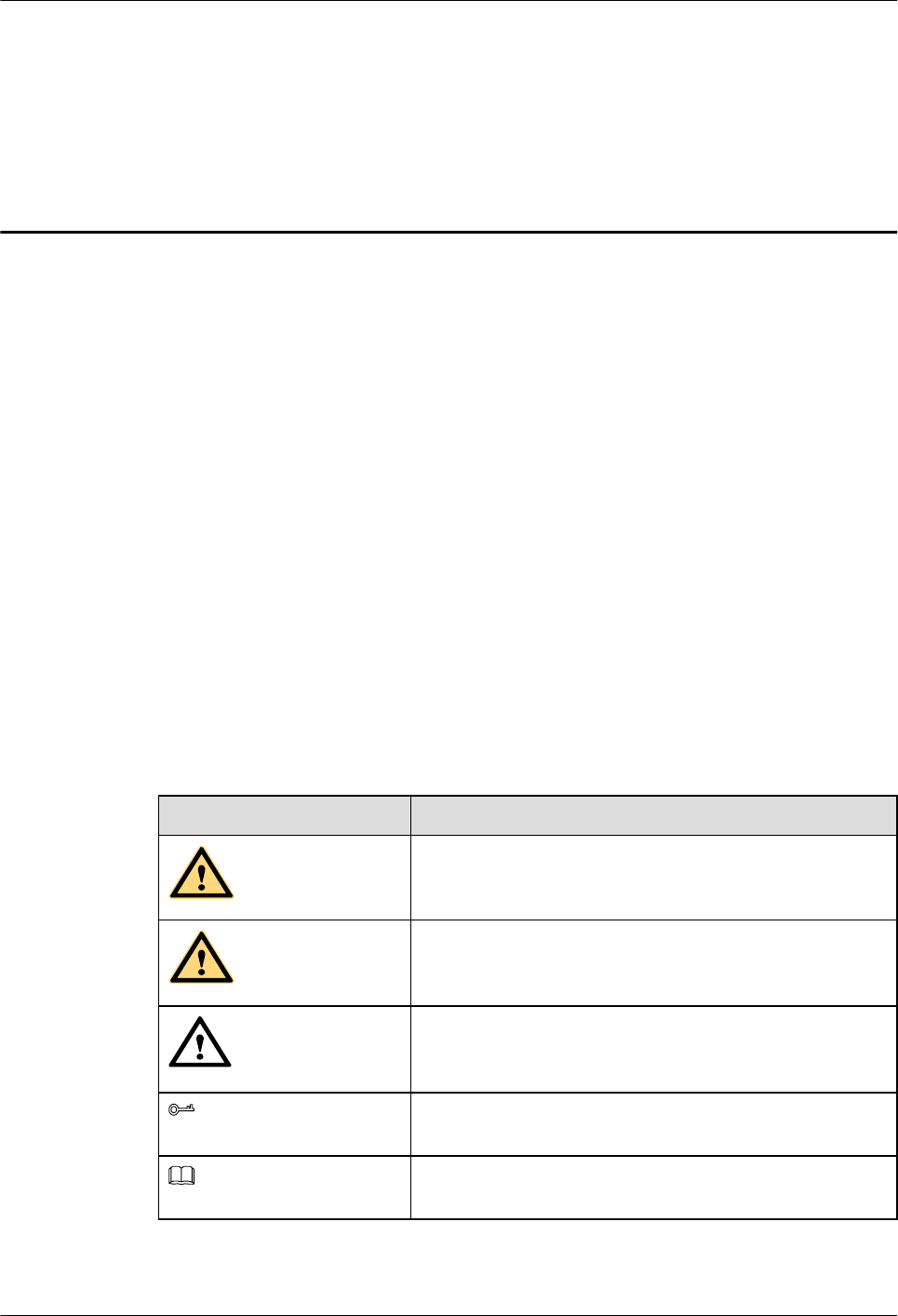
Symbol Conventions
The symbols that may be found in this document are defined as follows.
Symbol Description
DANGER
Indicates a hazard with a high level of risk, which if not
avoided, will result in death or serious injury.
WARNING
Indicates a hazard with a medium or low level of risk, which
if not avoided, could result in minor or moderate injury.
CAUTION
Indicates a potentially hazardous situation, which if not
avoided, could result in equipment damage, data loss,
performance degradation, or unexpected results.
TIP
Indicates a tip that may help you solve a problem or save
time.
NOTE
Provides additional information to emphasize or supplement
important points of the main text.
Huawei AR1200-S&2200-S Series Enterprise Routers
Hardware Description About This Document
Issue 03 (2012-04-20) Huawei Proprietary and Confidential
Copyright © Huawei Technologies Co., Ltd.
ii

Change History
Changes between document issues are cumulative. Therefore, the latest document issue contains
all the changes in previous issues.
Changes in Issue 02 (2012-03-30)
Based on issue 01 (2011-12-30), this issue has the following updates:
lThe AR2220-S model is added.
Changes in Issue 01 (2011-12-30)
Initial commercial release.
Huawei AR1200-S&2200-S Series Enterprise Routers
Hardware Description About This Document
Issue 03 (2012-04-20) Huawei Proprietary and Confidential
Copyright © Huawei Technologies Co., Ltd.
iii

Contents
About This Document.....................................................................................................................ii
1 Version Matching..........................................................................................................................1
1.1 Matching Between Product Models and Software Versions..............................................................................2
1.2 Matching Between Power Supplies and Software Versions..............................................................................2
1.3 Matching Between Cards and Software Versions..............................................................................................3
2 Chassis.............................................................................................................................................7
2.1 Introduction........................................................................................................................................................8
2.2 Naming Convention............................................................................................................................................8
2.3 Device Structure.................................................................................................................................................9
2.3.1 AR1200-S Series.......................................................................................................................................9
2.3.2 AR2200-S Series.....................................................................................................................................12
2.4 System Configuration.......................................................................................................................................14
2.5 Physical Specifications.....................................................................................................................................14
3 Power Supply Units....................................................................................................................16
3.1 Power Supply Configuration............................................................................................................................17
3.2 Power Supply Unit Connection Layouts..........................................................................................................17
3.2.1 Single Non-PoE AC Power Supply Unit.................................................................................................17
3.2.2 Single Non-PoE + PoE AC Power Supply Unit......................................................................................18
3.3 HW-100-48AC14D..........................................................................................................................................19
4 Heat Dissipation System............................................................................................................23
4.1 Heat Dissipation Process..................................................................................................................................24
5 Cards..............................................................................................................................................25
5.1 Introduction......................................................................................................................................................26
5.1.1 Relationships Between Cards..................................................................................................................26
5.1.2 Interface Numbering................................................................................................................................27
5.1.3 Card Dimensions.....................................................................................................................................28
5.2 WLAN Subcard................................................................................................................................................29
5.2.1 Functions and Applications.....................................................................................................................29
5.2.2 Technical Specifications..........................................................................................................................29
5.3 Ethernet LAN Interface Card............................................................................................................................29
5.3.1 8FE1GE-8-Port 100BASE-RJ45 and 1-Port 1000BASE-RJ45 L2/L3 Ethernet Interface Card.............30
Huawei AR1200-S&2200-S Series Enterprise Routers
Hardware Description Contents
Issue 03 (2012-04-20) Huawei Proprietary and Confidential
Copyright © Huawei Technologies Co., Ltd.
iv

5.3.2 24GE-24-Port 1000BASE-RJ45 L2/L3 Ethernet Interface Card............................................................33
5.4 WAN Interface Card.........................................................................................................................................36
5.4.1 1GEC (1-Port-GE Combo WAN Interface Card)....................................................................................36
5.4.2 2FE-2-Port-FE WAN Interface Card.......................................................................................................40
5.4.3 1E1T1-M/2E1T1-M-1/2 Port-Channelized E1/T1/PRI/VE1 Multifunctional Interface Card................42
5.4.4 1E1T1-F/2E1T1-F (1/2-Port-Fractional Channelized E1/T1 WAN Interface Card)..............................47
5.4.5 1SA/2SA-1/2-Port-Synchronous/Asynchronous WAN Interface Card..................................................50
5.4.6 8AS (8-Port-Asynchronous WAN Interface Card)..................................................................................54
5.4.7 1BST (1-Port-ISDN S/T WAN Interface Card)......................................................................................56
5.4.8 1CPOS-155M (1-Port Channelized POS Interface Card).......................................................................59
5.4.9 3G-HSPA+7 (3G WAN Interface Card).................................................................................................62
5.4.10 4GEW-T (4-Port-GE Electrical WAN Interface Card).........................................................................67
5.4.11 4GEW-S (4-Port-GE Optical WAN Interface Card..............................................................................69
5.5 Voice Interface Card.........................................................................................................................................73
5.5.1 2BST (2-Port-ISDN S/T Voice Interface Card)......................................................................................73
5.5.2 4FXS1FXO-4-Port FXS and 1-Port FXO Voice Interface Card.............................................................77
5.5.3 16/32/64/128-Channel DSP Module.......................................................................................................80
5.6 xDSL Interface Card.........................................................................................................................................81
5.6.1 ADSL-A/M and ADSL-B-1-Port-ADSL2+ ANNEX A/M and B WAN Interface Card........................81
5.6.2 4G.SHDSL-1-Port-4-Channel G.SHDSL WAN Interface Card.............................................................85
5.6.3 1PON (1-Port GPON/EPON Dual-Mode Interface Card).......................................................................87
5.6.4 VDSL (1-Port VDSL2 over POTS WAN Interface Card)......................................................................91
6 Cables.............................................................................................................................................95
6.1 AC Power Cable...............................................................................................................................................97
6.2 DC Power Cables..............................................................................................................................................98
6.3 Ground Cable..................................................................................................................................................100
6.4 Console Cable.................................................................................................................................................101
6.5 Network Cable................................................................................................................................................102
6.6 Optical Fiber...................................................................................................................................................105
6.7 E1/T1 Trunk Cables........................................................................................................................................109
6.8 Synchronous/Asynchronous Serial Interface Cables......................................................................................114
6.9 4G.SHDSL Cables..........................................................................................................................................120
6.10 ISDN-ST Cables...........................................................................................................................................122
6.11 Regular Telephone Lines..............................................................................................................................126
6.12 8AS Cable.....................................................................................................................................................127
6.13 3G Antenna...................................................................................................................................................132
7 List of Indicators........................................................................................................................136
7.1 Indicators on the AR1200-S Panel.................................................................................................................137
7.2 Indicators on the AR2220-S Panel.................................................................................................................140
7.3 Power Indicators.............................................................................................................................................142
8 List of Cards................................................................................................................................145
Huawei AR1200-S&2200-S Series Enterprise Routers
Hardware Description Contents
Issue 03 (2012-04-20) Huawei Proprietary and Confidential
Copyright © Huawei Technologies Co., Ltd.
v

8.1 Cards Supported by the AR............................................................................................................................146
8.2 Power Consumption and Weight....................................................................................................................149
9 List of Interface Attributes.......................................................................................................150
9.1 Electrical Interfaces........................................................................................................................................152
9.2 GE/PON Optical Interface Attributes.............................................................................................................153
9.3 CPOS Interface Attributes..............................................................................................................................155
9.4 E1 Interface Attributes....................................................................................................................................156
9.5 T1 Interface Attributes....................................................................................................................................157
9.6 Synchronous/Asynchronous Serial Interface Attributes.................................................................................158
9.7 ISDN S/T Interface Attributes........................................................................................................................159
9.8 FXS/FXO Interface Attributes........................................................................................................................159
9.9 ADSL2/ADSL2+/G.SHDSL Interface Attributes..........................................................................................161
9.10 Attributes of the Console Interface...............................................................................................................162
9.11 Attributes of the USB Interface....................................................................................................................162
9.12 3G Interface Attributes.................................................................................................................................163
9.13 VDSL Interface Attributes............................................................................................................................164
Huawei AR1200-S&2200-S Series Enterprise Routers
Hardware Description Contents
Issue 03 (2012-04-20) Huawei Proprietary and Confidential
Copyright © Huawei Technologies Co., Ltd.
vi

1 Version Matching
About This Chapter
This section describes the matching relationships between the chassis, power supplies, cards,
and system software versions of AR routers.
NOTE
lAR version roadmap: ARV200R001C01, ARV200R002C00, ARV200R002C01.
lUnless otherwise specified, if a power supply or card is supported by version A, it is also supported by
all versions later than version A.
1.1 Matching Between Product Models and Software Versions
This section describes the matching relationship between AR models and software versions.
1.2 Matching Between Power Supplies and Software Versions
This section describes the matching relationships between power supplies, power modes, and
software versions.
1.3 Matching Between Cards and Software Versions
This section describes the cards supported by AR routers, including SRUs, Ethernet LAN
interface cards, WAN interface cards, voice interface cards, and xDSL/xPON interface cards.
Huawei AR1200-S&2200-S Series Enterprise Routers
Hardware Description 1 Version Matching
Issue 03 (2012-04-20) Huawei Proprietary and Confidential
Copyright © Huawei Technologies Co., Ltd.
1
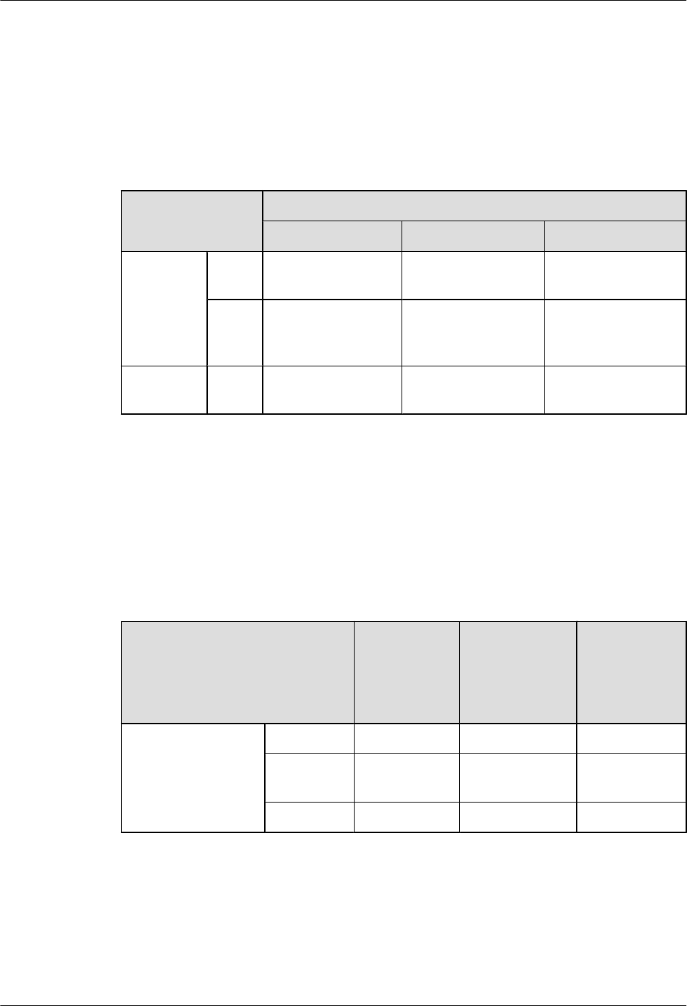
1.1 Matching Between Product Models and Software
Versions
This section describes the matching relationship between AR models and software versions.
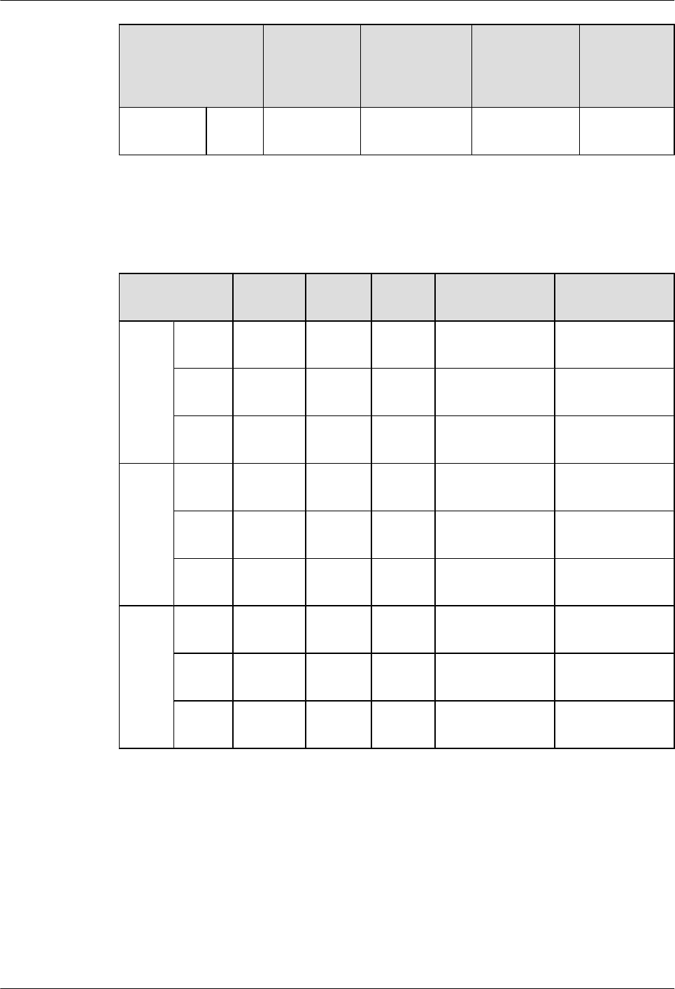
Table 1-1 Matching between product models and software versions
Model Software Version
ARV200R001C01 ARV200R002C00 ARV200R002C01
AR1200-S
series
AR12
20-S
√ √ √
AR12
20W-
S
√ √ √
AR2200-S
series
AR22
20-S
√ × √
1.2 Matching Between Power Supplies and Software
Versions
This section describes the matching relationships between power supplies, power modes, and
software versions.
Table 1-2 Matching between power supplies and software versions
Model&Version 60 W AC
Power
Supply Unit
in an Open
Rack
3.3
HW-100-48AC
14D
PWR150A
ARV200R001C01&
ARV200R002C00&
ARV200R002C01
AR1220-S √ × ×
AR1220W-
S
√ √ ×
AR2220-S × × √
Huawei AR1200-S&2200-S Series Enterprise Routers
Hardware Description 1 Version Matching
Issue 03 (2012-04-20) Huawei Proprietary and Confidential
Copyright © Huawei Technologies Co., Ltd.
2

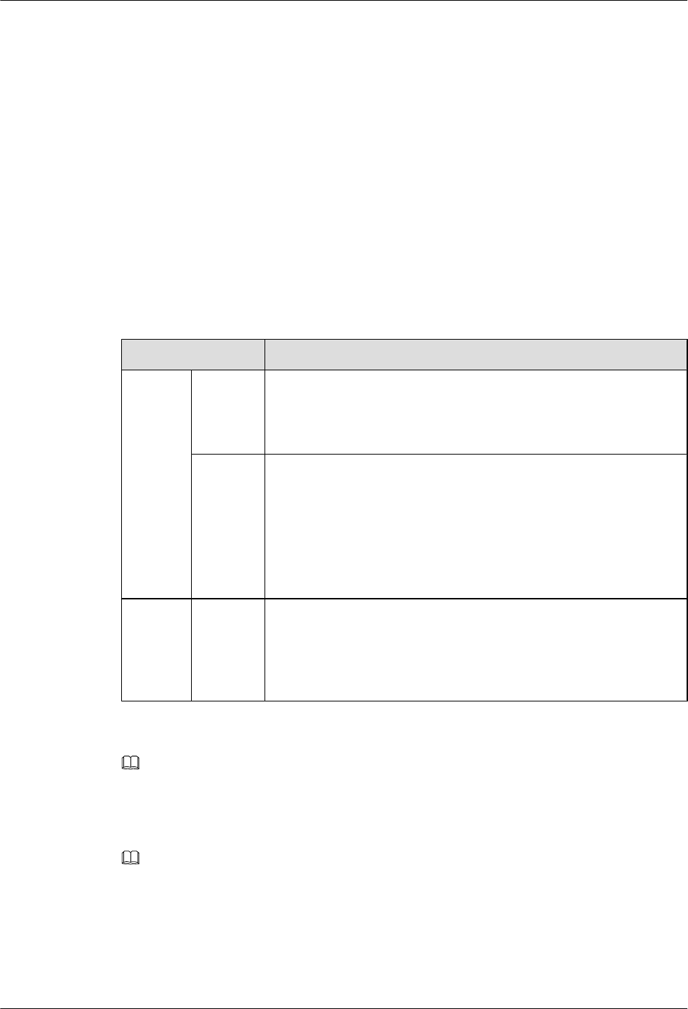
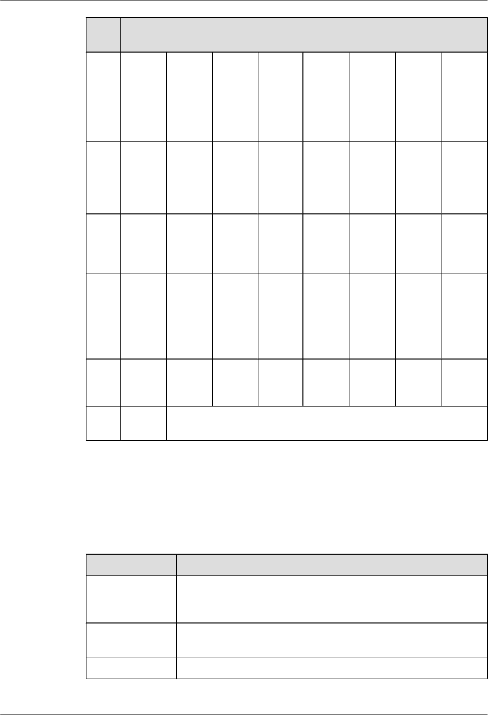
Table 1-3 Matching between power modes and software versions
Model&Versi
on
Single
DC
Power
Supply
Unit
Dual DC
Power
Supply
Units
Single
Non-PoE
AC Power
Supply
Unit
Dual Non-
PoE AC
Power
Supply
Units
Single
Non-PoE
+ PoE AC
Power
Supply
Unit
ARV2
00R0
01C0
1&A
RV20
0R00
2C00
&AR
V200
R002
C01
AR12
20-S
× × √ × ×
AR12
20W-S
× × √ × √
AR22
20-S
× × √ × ×
1.3 Matching Between Cards and Software Versions
This section describes the cards supported by AR routers, including SRUs, Ethernet LAN
interface cards, WAN interface cards, voice interface cards, and xDSL/xPON interface cards.
Matching between physical cards and software versions
Table 1-4 Matching between physical cards and software versions
Model&Version SIC WSIC XSIC voice card
ARV200R001C0
1&ARV200R002
C00&ARV200R0
02C01
AR1220-
S
√ √ × ×
AR1220
W-S
√ √ × ×
AR2220-
S
√ √ √ √
Matching between SRUs and software versions
Table 1-5 Matching between SRUs and software versions
Model&Version SRU WLAN Subcard
ARV200R001C0
1&ARV200R002
AR1220-S × ×
Huawei AR1200-S&2200-S Series Enterprise Routers
Hardware Description 1 Version Matching
Issue 03 (2012-04-20) Huawei Proprietary and Confidential
Copyright © Huawei Technologies Co., Ltd.
3
Model&Version SRU WLAN Subcard
C00&ARV200R
002C01
AR1220W-S × √
AR2220-S × ×
Matching between Ethernet LAN interface cards and software versions
Table 1-6 Matching between Ethernet LAN interface cards and software versions
Model&Version 8FE1GE 24GE
ARV200R001C0
1&ARV200R002
C00&ARV200R
002C01
AR1220-S √ ×
AR1220W-S √ ×
AR2220-S √ √
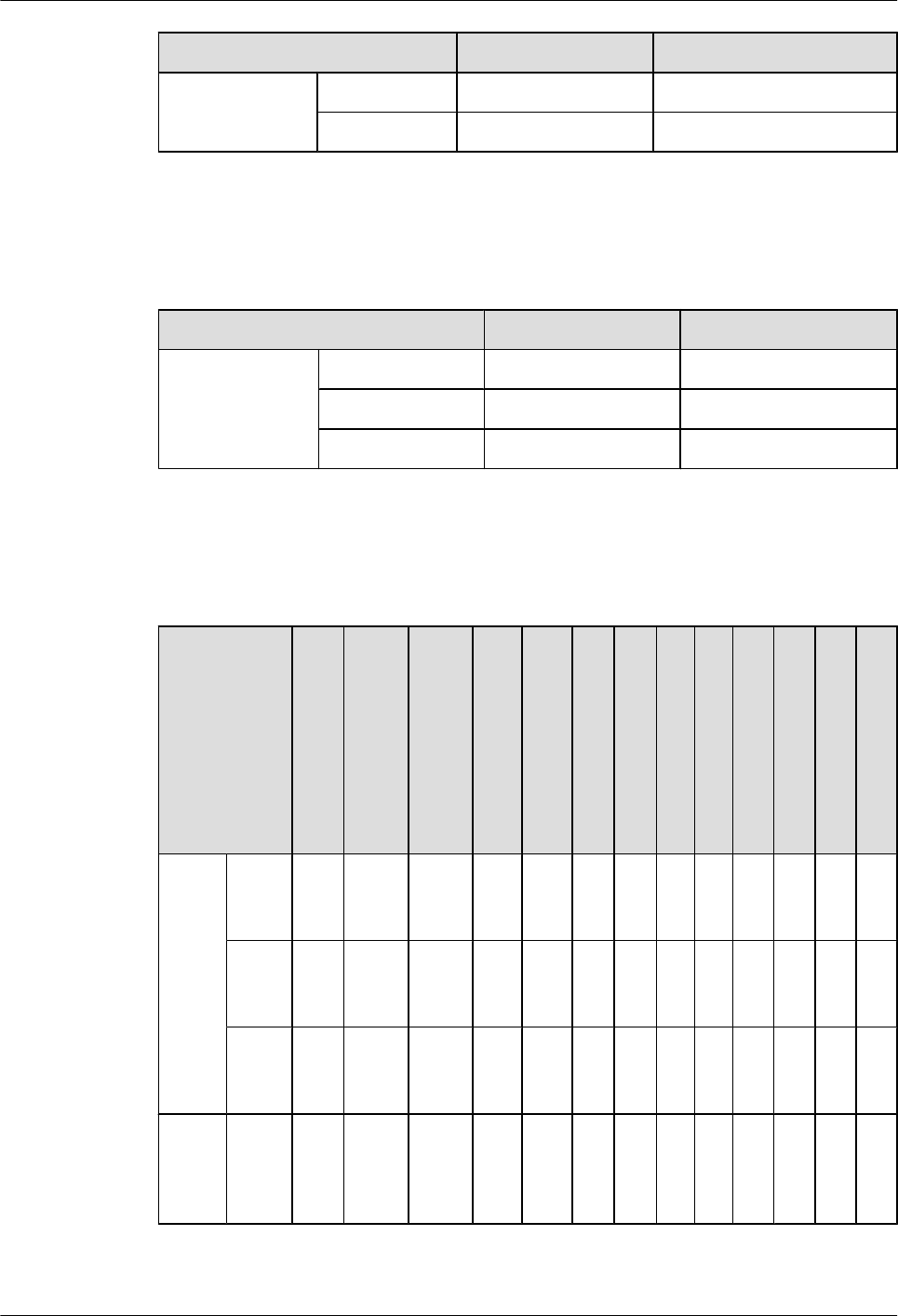
Matching between WAN cards and software versions
Table 1-7 Matching between WAN cards and software versions
Model&Ver
sion
2F
E
1E1
T1-
M/
2E1
T1-
M
(SIC
)
2E1
T1-
M
(WS
IC)
1E
1T
1-
F/
2E
1T
1-F
1S
A
2S
A
1
G
E
C
8
A
S
1
B
S
T
1
C
P
O
S-
15
5
M
3
G
-
H
S
P
A
+
7
4
G
E
W
-T
4
G
E
W
-S
ARV
200R
001C
01
AR1
220-
S
√ √ × √ √ √ √ √ √ × × × ×
AR1
220
W-S
√ √ × √ √ √ √ √ √ × × × ×
AR2
220-
S
√ √ × √ √ √ √ √ √ √ × × ×
ARV
200R
002C
00
AR1
220-
S
√ √ √ √ √ √ √ √ √ × × × ×
Huawei AR1200-S&2200-S Series Enterprise Routers
Hardware Description 1 Version Matching
Issue 03 (2012-04-20) Huawei Proprietary and Confidential
Copyright © Huawei Technologies Co., Ltd.
4
Model&Ver
sion
2F
E
1E1
T1-
M/
2E1
T1-
M
(SIC
)
2E1
T1-
M
(WS
IC)
1E
1T
1-
F/
2E
1T
1-F
1S
A
2S
A
1
G
E
C
8
A
S
1
B
S
T
1
C
P
O
S-
15
5
M
3
G
-
H
S
P
A
+
7
4
G
E
W
-T
4
G
E
W
-S
AR1
220
W-S
√ √ √ √ √ √ √ √ √ × × × ×
AR2
220-
S
√ √ √ √ √ √ √ √ √ √ × × ×
ARV
200R
002C
01
AR1
220-
S
√ √ √ √ √ √ √ √ √ × √ √ √
AR1
220
W-S
√ √ √ √ √ √ √ √ √ × √ √ √
AR2
220-
S
√ √ √ √ √ √ √ √ √ √ √ √ √
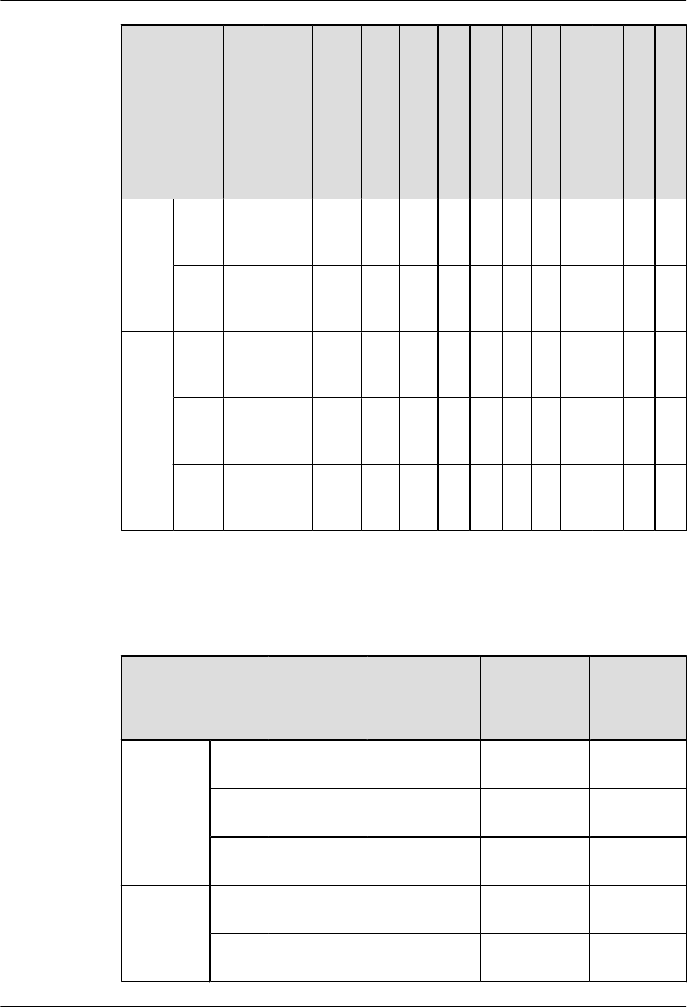
Matching between voice cards and software versions
Table 1-8 Matching between voice cards and software versions
Model&Version 4FXS1FXO 2BST(SIC) 2BST(WSIC) 16/32/64/128
-Channel
DSP
Module
ARV200R0
01C01
AR12
20-S
× × × ×
AR12
20W-S
× × × ×
AR22
20-S
√ √ × √
ARV200R0
02C00&AR
V200R002
C01
AR12
20-S
× × × ×
AR12
20W-S
× × × ×
Huawei AR1200-S&2200-S Series Enterprise Routers
Hardware Description 1 Version Matching
Issue 03 (2012-04-20) Huawei Proprietary and Confidential
Copyright © Huawei Technologies Co., Ltd.
5
Model&Version 4FXS1FXO 2BST(SIC) 2BST(WSIC) 16/32/64/128
-Channel
DSP
Module
AR22
20-S
√ √ √ √
Matching between xDSL/xPON cards and software versions
Table 1-9 Matching between xDSL/xPON cards and software versions
Model&Versi
on
ADSL-
A/M
ADSL-
B
4G.SH
DSL
1PON VDSL
ARV2
00R00
1C01
AR122
0-S
√ √ √ × ×
AR122
0W-S
√ √ √ × ×
AR222
0-S
√ √ √ × ×
ARV2
00R00
2C00
AR122
0-S
√ √ √ √ ×
AR122
0W-S
√ √ √ √ ×
AR222
0-S
√ √ √ √ ×
ARV2
00R00
2C01
AR122
0-S
√ √ √ √ √
AR122
0W-S
√ √ √ √ √
AR222
0-S
√ √ √ √ √
Huawei AR1200-S&2200-S Series Enterprise Routers
Hardware Description 1 Version Matching
Issue 03 (2012-04-20) Huawei Proprietary and Confidential
Copyright © Huawei Technologies Co., Ltd.
6

2 Chassis
About This Chapter
This section describes the characteristics, naming rules, appearance, structure, system
performance, and technical specifications of the AR routers.
2.1 Introduction
This section briefly describes the AR routers and the models available.
2.2 Naming Convention
This section describes the naming conventions used when naming AR routers.
2.3 Device Structure
This section describes the structure of the AR routers.
2.4 System Configuration
2.5 Physical Specifications
Huawei AR1200-S&2200-S Series Enterprise Routers
Hardware Description 2 Chassis
Issue 03 (2012-04-20) Huawei Proprietary and Confidential
Copyright © Huawei Technologies Co., Ltd.
7
2.1 Introduction
This section briefly describes the AR routers and the models available.
Description
Huawei AR Enterprise Router (AR router for short) are the next-generation routers integrating
data,voice, security, routing, switching, and virtual private network (VPN) functions. As an
egress gateway for enterprises, the AR routers use the multi-core CPU processing capabilities
and rapid expansibility.
Models
The AR routers offer the following models.
Model Characteristics
AR1200
-S
AR1220-
S
The AR1220-S is 1 U high (1 U = 44.45 mm [1.75 in.]), uses a 60 W
open frame AC power supply, and supports two SIC slots. The
integrated SRU provides eight fixed FE interfaces and two fixed GE
electrical interfaces.
AR1220
W-S
lCompared with the AR1220-S, the AR1220W-S supports the Wi-
Fi function and external PoE power supply unit. The last four FE
interfaces (FE4-FE7) on the main control unit support the PoE
function.
lThe silkscreen on the rear side of AR1220W-S chassis is
AR1220W-S and two antennas and a PoE power supply port are
provided.
AR2200 AR2220-
S
The AR2220-S is 1 U high (1 U = 44.45 mm), uses a 150 W AC power
supply unit, and supports four SIC cards and two WSIC cards. The
integrated SRU supports fixed 3GE interfaces (including one combo
interface). The backplane is in the middle of the chassis, and cards
are installed on the front and rear sides of the backplane.
NOTE
lSIC: Service Interface Card. This is the smallest card supported by ARs.
lWSIC: Wide SIC. The same height as a SIC, but twice the width.
lXSIC: Extended SIC. Double the height and width of an XSIC and twice those of a SIC.
NOTE
In this document, AR1200–S indicates AR1220–S and AR1220W–S.
2.2 Naming Convention
This section describes the naming conventions used when naming AR routers.
Huawei AR1200-S&2200-S Series Enterprise Routers
Hardware Description 2 Chassis
Issue 03 (2012-04-20) Huawei Proprietary and Confidential
Copyright © Huawei Technologies Co., Ltd.
8
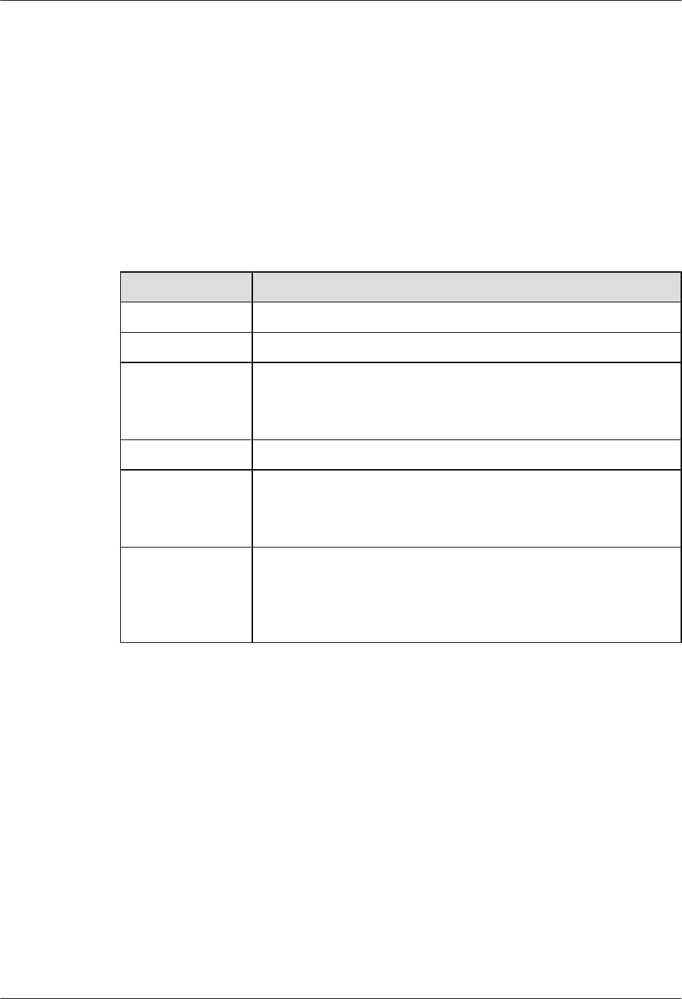
Figure 2-1 Naming convention
【AR】【B1 B2 B3 B4】【C1】【-D1】
Example:
AR1220 -S
Table 2-1 Naming convention of AR routers
Field Description
B1 Product series code. AR routers includes series 1 and 2.
B2 Fixed as 2, indicating enterprise router.
B3 Number of service card slots (dependent on B1):
lWhen B1 is 1, B3 indicates the number of SIC cards.
lWhen B1 is 2, B3 indicates the number of WSIC and XSIC cards.
B4 The value is fixed as 0.
C1 C1 contains one or two upper-case letters.
lW: WLAN
lV: voice
D1 lA: AC (This is the default configuration, so A is not contained in
the product name)
lD: DC
lS: Soho
2.3 Device Structure
This section describes the structure of the AR routers.
2.3.1 AR1200-S Series
This section describes the structure of the AR1200-S.
Appearance
Figure 2-2 and Figure 2-3 show front views of AR1200-S.
Huawei AR1200-S&2200-S Series Enterprise Routers
Hardware Description 2 Chassis
Issue 03 (2012-04-20) Huawei Proprietary and Confidential
Copyright © Huawei Technologies Co., Ltd.
9
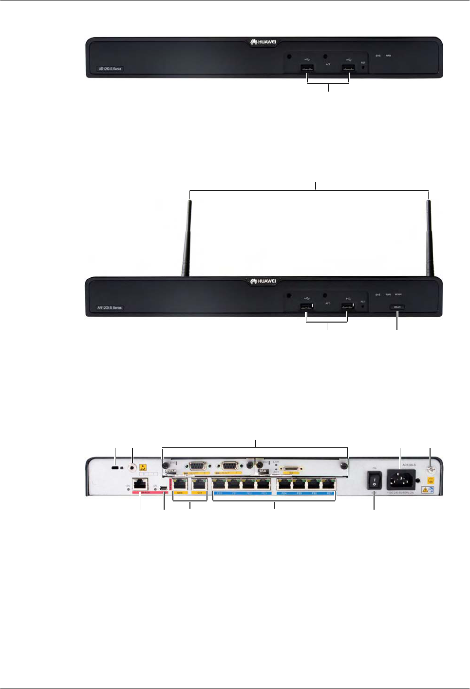
Figure 2-2 AR1220-S front view
18
Figure 2-3 AR1220W-S front view
2018
19
Figure 2-4 and Figure 2-5 show rear views of AR1200-S.
Figure 2-4 AR1220-S rear view
2 4 3
1
7
1012131415
Huawei AR1200-S&2200-S Series Enterprise Routers
Hardware Description 2 Chassis
Issue 03 (2012-04-20) Huawei Proprietary and Confidential
Copyright © Huawei Technologies Co., Ltd.
10
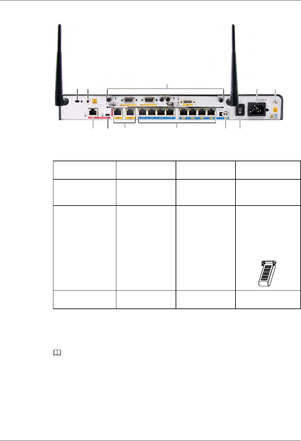
Figure 2-5 AR1220W-S rear view
2 4 3
1
7
101213 111415
1: Pluggable card 2: ESD jack 3: Ground screw 4: AC jack
7: Security lock 10: AC power switch 11: PoE port 12: Fixed 8FE interface
on the panel
13: Two Fixed GE
interfaces on the panel
14: Mini USB
interface
15: CON/AUX
interface
18: USB interfaces
NOTE
After a 3G USB modem
is inserted, install a
protection cap on it, as
shown in the following
figure.
19: Antenna 20: WLAN switch
Slot Distribution
Figure 2-6 shows slot distribution on AR1200-S.
NOTE
lTwo SIC slots can be combined into one WSIC slot by removing the guide rail.
lSlots can be combined into one, but one slot cannot be divided into multiple slots.
lAfter two slots are combined into one, the slot ID is the larger number of the two original slots.
Huawei AR1200-S&2200-S Series Enterprise Routers
Hardware Description 2 Chassis
Issue 03 (2012-04-20) Huawei Proprietary and Confidential
Copyright © Huawei Technologies Co., Ltd.
11
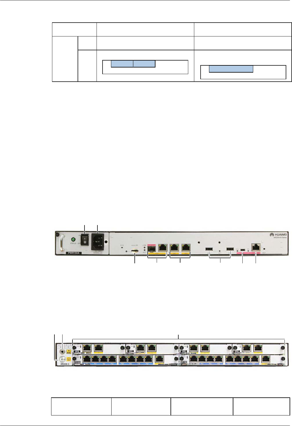
Figure 2-6 AR1200-S slot distribution on
Front
view
Rear
view
Device Model Slot Distribution
AR1200
-S
NA
Two SIC slots are combined into
one WSIC slot
NA
1(SIC)2(SIC)
0(SRU)
Slot Combination
2(WSIC)
0(SRU)
As shown in Figure 2-6, the slots of AR1200-S can be combined :
Slot 1 and slot 2 are combined into new slot 2.
2.3.2 AR2200-S Series
This section describes the structure of the AR2200-S.
Appearance
Figure 2-7 show front views of AR2200-S.
Figure 2-7 AR2220-S front view
410
14 151317 1816
Figure 2-8 show rear views of AR2200-S.
Figure 2-8 AR2220-S rear view
123
1: Pluggable card 2: ESD jack 3: Ground screw 4: AC jack
Huawei AR1200-S&2200-S Series Enterprise Routers
Hardware Description 2 Chassis
Issue 03 (2012-04-20) Huawei Proprietary and Confidential
Copyright © Huawei Technologies Co., Ltd.
12
10: AC power switch 13: Two Fixed GE
interfaces on the panel
14: Mini USB interface 15: CON/AUX
interface
16: Micro SD card
interface
17: GE optical/
electrical Combo
interface
18: USB interfaces
NOTE
After a 3G USB modem
is inserted, install a
protection cap on it, as
shown in the following
figure.
Slot Distribution
Figure 2-9 shows slot distribution on AR2200-S.
NOTE
lTwo SIC slots can be combined into one WSIC slot by removing the guide rail.
lTwo SIC slots and one WSIC slot can be combined into one XSIC slot by removing the guide rail.
lTwo XSIC slots can be combined into one EXSIC slot by removing the guide rail.
lSlots can be combined into one, but one slot cannot be divided into multiple slots.
lAfter two slots are combined into one, the slot ID is the larger number of the two original slots.
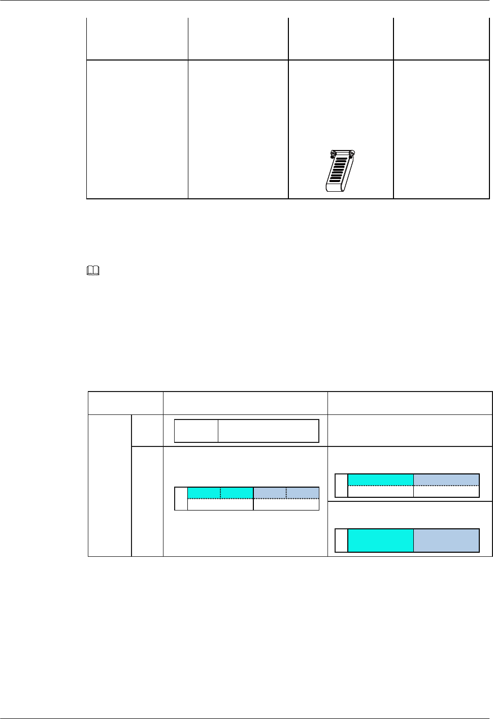
Figure 2-9 AR2200-S slot distribution
AR2220
-S
NA
0(SRU)7(Power)
Front
view
Rear
view
Device Model Slot Distribution
Two SIC slots are combined into
one WSIC slot
Slot Combination
Two WSIC slots are combined
into one XSIC slot
5(XSIC)6(XSIC)
2(WSIC)4(WSIC)
5(WSIC)6(WSIC)
2(SIC)3(SIC)4(SIC)
5(WSIC)6(WSIC)
1(SIC)
As shown in Figure 2-9, the slots of AR2200-S can be combined :
lAR2220-S
–Slot 1 and slot 2 are combined into new slot 2.
–Slot 3 and slot 4 are combined into new slot 4.
–New slot 2 and slot 5 are combined into new slot 5.
–New slot 4 and slot 6 are combined into new slot 6.
Huawei AR1200-S&2200-S Series Enterprise Routers
Hardware Description 2 Chassis
Issue 03 (2012-04-20) Huawei Proprietary and Confidential
Copyright © Huawei Technologies Co., Ltd.
13
2.4 System Configuration
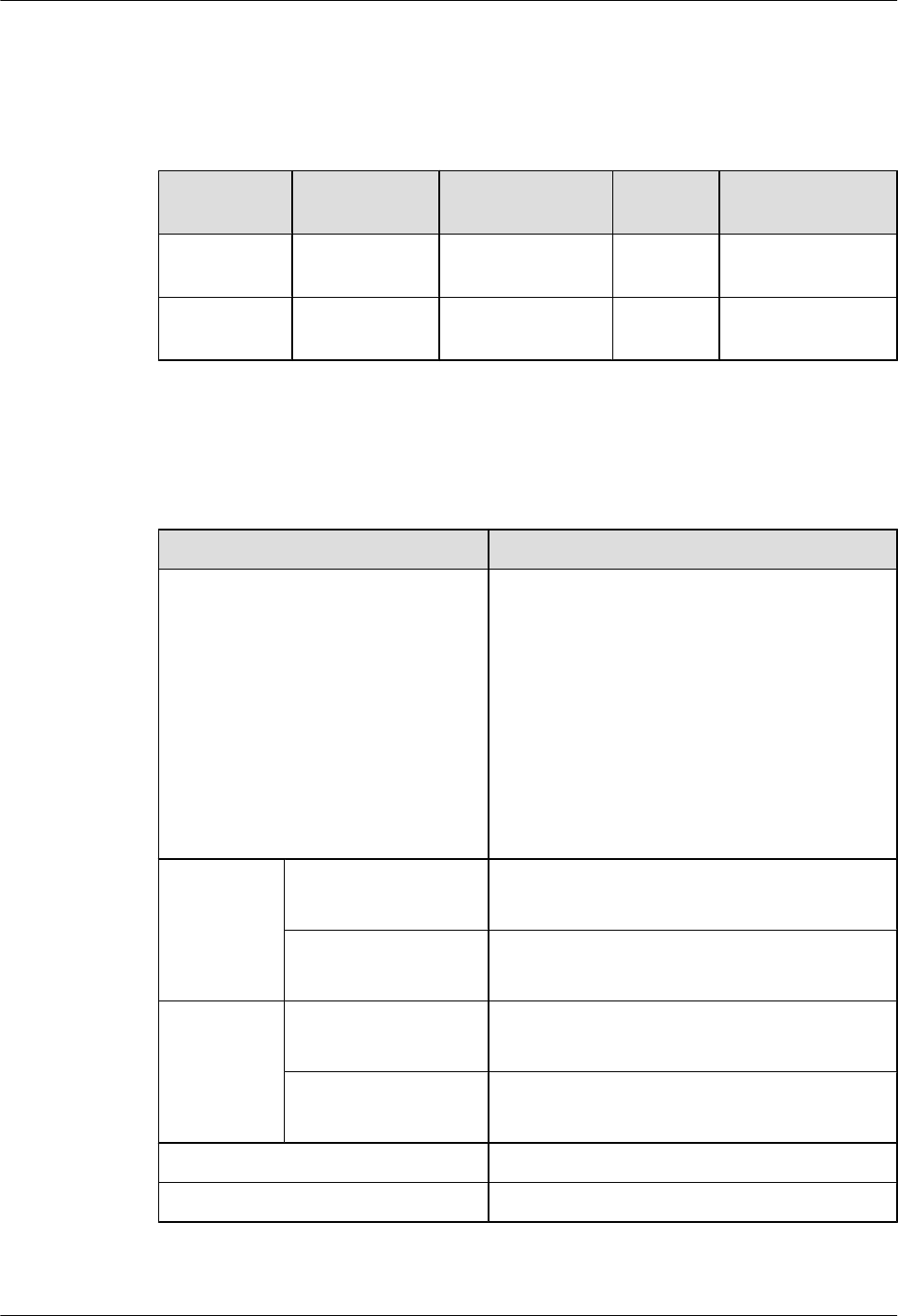
Table 2-2 System configuration
Model Processor Memory Flash
Memory
Micro SD Card
AR1200-S
Series
2-core: 500
MHz
512 MB 256 MB 0
AR2220-S 4-core: 600
MHz
2 GB 16 MB 2 GB
2.5 Physical Specifications
Table 2-3 Physical specifications
Item Description
Dimensions (width x depth x height) lWithout rack-mounting ear:
–AR1200-S: 390.0 mm x 220.0 mm x 44.5
mm (15.35 in. x 8.66 in. x 1.75 in.)
–AR2220-S: 442.0 mm x 420.0 mm x 44.5
mm (17.4 in. x 16.54 in. x 1.75 in.)
lWith rack-mounting ear:
–AR1200-S: 482.6 mm x 220.0 mm x 44.5
mm (19 in. x 8.66 in. x 1.75 in.)
–AR2220-S: 482.6 mm x 420.0 mm x 44.5
mm (19 in. x 16.54 in. x 1.75 in.)
Maximum
power
consumption
Full configuration lAR1200-S: 52 W
lAR2220-S: 95 W
Empty chassis lAR1200-S: 33.3 W
lAR2220-S: 65.1 W
Weight Full configuration lAR1200-S: 3.60 kg (7.94 lb)
lAR2220-S: 8.45 kg (18.63 lb)
Empty chassis lAR1200-S: 2.90 kg (6.39 lb)
lAR2220-S: 4.95 kg (10.91 lb)
Operating temperature 0°C to 40°C (0°F to 104°F)
Relative humidity 5% RH to 90% RH, non-condensing
Huawei AR1200-S&2200-S Series Enterprise Routers
Hardware Description 2 Chassis
Issue 03 (2012-04-20) Huawei Proprietary and Confidential
Copyright © Huawei Technologies Co., Ltd.
14

Item Description
Altitude Long-term operating
altitude
Below 4000 m (13123.2 ft.)
Storage altitude Below 4000 m (13123.2 ft.)
AC input
voltage
Rated voltage 100 V AC to 240 V AC, 50/60Hz
Maximum voltage 85 V AC to 264 V AC, 47/63Hz
Huawei AR1200-S&2200-S Series Enterprise Routers
Hardware Description 2 Chassis
Issue 03 (2012-04-20) Huawei Proprietary and Confidential
Copyright © Huawei Technologies Co., Ltd.
15
3 Power Supply Units
About This Chapter
This section describes the power supply units supported by the AR routers.
CAUTION
lPower off the AR routers before removing or performing maintenance on the power supply
units.
lTo power off the AR routers , power off all its power supply units.
3.1 Power Supply Configuration
This section describes the configurations of power supply units on the AR routers.
3.2 Power Supply Unit Connection Layouts
This section illustrates the connection between each power supply unit and the motherboard.
3.3 HW-100-48AC14D
This section describes the HW-100-48AC14D power supply unit, including the naming
convention, functions, appearance, and technical specifications.
Huawei AR1200-S&2200-S Series Enterprise Routers
Hardware Description 3 Power Supply Units
Issue 03 (2012-04-20) Huawei Proprietary and Confidential
Copyright © Huawei Technologies Co., Ltd.
16

3.1 Power Supply Configuration
This section describes the configurations of power supply units on the AR routers.
Table 3-1 describes the power supply units supported by each model.
Table 3-1 Power supply units supported by each model
Power Supply Unit Description Installation Maintenance
60 W AC power
supply unit in an open
rack
AC power supply
unit fixed in the
chassis
Fixed in the chassis,
does not need to be
connected to the
chassis using
cables.
Maintain together with
the chassis.
3.3
HW-100-48AC14D
External PoE AC
power supply unit
Connected to the
PoE port at the back
of the chassis using
its own power
cable.
Maintain
independently from the
chassis.
PWR150A AC power supply
unit
Inserted into a
power supply slot.
The device supports
only one power
supply unit.
Maintain together with
the chassis.
3.2 Power Supply Unit Connection Layouts
This section illustrates the connection between each power supply unit and the motherboard.
3.2.1 Single Non-PoE AC Power Supply Unit
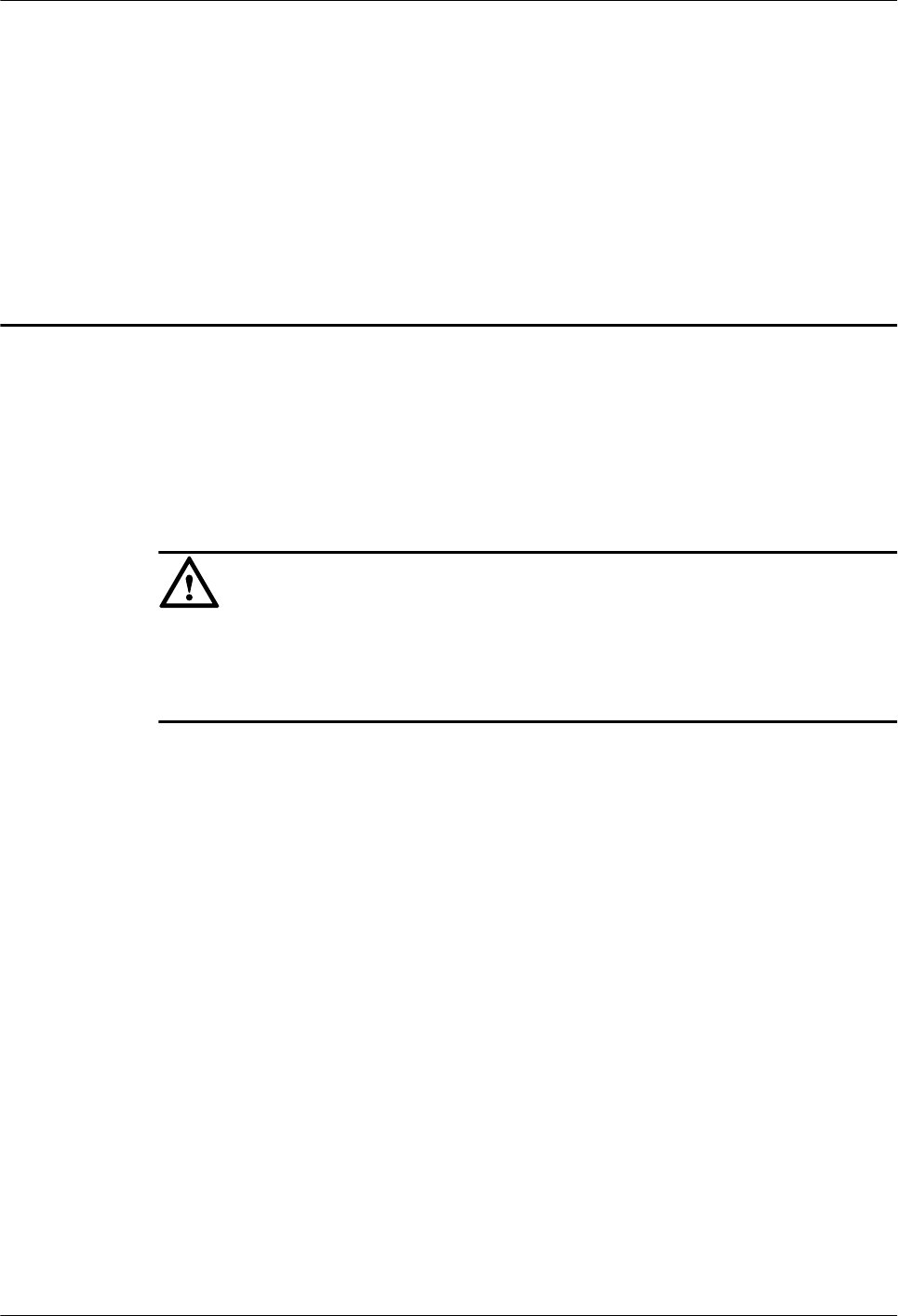
Figure 3-1 shows the layout of single non-PoE AC power supply unit connection to
motherboard.
Huawei AR1200-S&2200-S Series Enterprise Routers
Hardware Description 3 Power Supply Units
Issue 03 (2012-04-20) Huawei Proprietary and Confidential
Copyright © Huawei Technologies Co., Ltd.
17
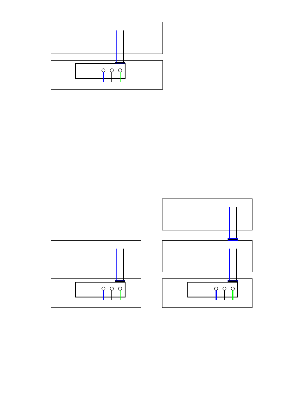
Figure 3-1 Layout of single non-PoE AC power supply unit connection to motherboard
Motherboard
GND12V
PWR
L N PGND
1. L: Live wire 2. N: Neutral wire 3. PGND: PGND wire 4. GND: Grounding
After the AC power is transmitted to the PWR module, the PWR module outputs 12 V voltage,
and then the motherboard provides power for the entire device.
3.2.2 Single Non-PoE + PoE AC Power Supply Unit
Figure 3-2 shows the layout of single non-PoE + PoE AC power supply unit connection to
motherboard.
Figure 3-2 Layout of single non-PoE + PoE AC power supply unit connection to motherboard
Motherboard
GND12V
PWR
L N PGND
PWR
L N PGND
RTN-53V
RTN-53V
PSE on the SRU
PoE Port (FE4~FE7)
1. L: Live wire 2. N: Neutral wire 3. PGND: PGND wire 4. GND: Grounding 5. RTN: Power ground cable
The non-PoE AC power supply unit and PoE AC power supply unit are independent of each
other:
lNon-PoE AC power supply unit: After the AC power is transmitted to the PWR module,
the PWR module outputs 12 V voltage, and then the motherboard provides power for the
entire device.
lPoE AC power supply unit: After the AC power is transmitted to the PoE module, the PoE
module outputs -53 V voltage, and then the PSE on the SRU provides power for the powered
devices (PDs) connected to the PoE interface.
Huawei AR1200-S&2200-S Series Enterprise Routers
Hardware Description 3 Power Supply Units
Issue 03 (2012-04-20) Huawei Proprietary and Confidential
Copyright © Huawei Technologies Co., Ltd.
18
3.3 HW-100-48AC14D
This section describes the HW-100-48AC14D power supply unit, including the naming
convention, functions, appearance, and technical specifications.
Naming Convention
Figure 3-3 illustrates the naming convention of the HW-100-48AC14D.
Figure 3-3 HW-100-48AC14D naming convention
HW-100-48AC14D
(1) (2) (3) (4) (5)
Number Description
(1) Product brand
(2) Output power parameters
l100: The output power is 100 W.
l48: The output voltage is 48 V.
(3) Power supply unit type
lA (Alternate): AC/DC power supply unit
lD (Direct): DC/DC power supply unit
(4) Socket type
lC14 is a type of socket.
(5) D (Desk), indicating the desktop power supply.
Functions
The HW-100-48AC14D uses 90 V AC-264 V AC input power, and provide 48 V/100 W output
power when no fan is used. Table 3-2 describes the protection functions provided by the
HW-100-48AC14D.
Huawei AR1200-S&2200-S Series Enterprise Routers
Hardware Description 3 Power Supply Units
Issue 03 (2012-04-20) Huawei Proprietary and Confidential
Copyright © Huawei Technologies Co., Ltd.
19

Table 3-2 Protection functions of the HW-100-48AC14D
Item Minimu
m Value
Typical
Value
Maximu
m Value
Remarks
Input
protecti
on
Input
undervolta
ge
protection
- - 62 V Input voltage can be
restored to the normal
range automatically.
Input
undervolta
ge recovery
- - 80 V Hysteresis is not smaller
than 5 V.
Output
protecti
on
Output
overvoltag
e protection
51 V - 58 V Output voltage can be
restored to the normal
range automatically.
Output
overcurrent
protection
2.5 A 3 A 3.5 A Output current can be
restored to the normal
range automatically.
Output
short-
circuit
protection
- - - Output short-circuit can be
recovered automatically.
Overheating protection - - - When temperature exceeds
the upper limit, the power
supply unit automatically
shuts down to avoid
permanent damage. No
smoke will be generated.
Temperature is reduced
below 55°C (131°F).
Appearance
Figure 3-4 shows the appearance of the HW-100-48AC14D.
Huawei AR1200-S&2200-S Series Enterprise Routers
Hardware Description 3 Power Supply Units
Issue 03 (2012-04-20) Huawei Proprietary and Confidential
Copyright © Huawei Technologies Co., Ltd.
20
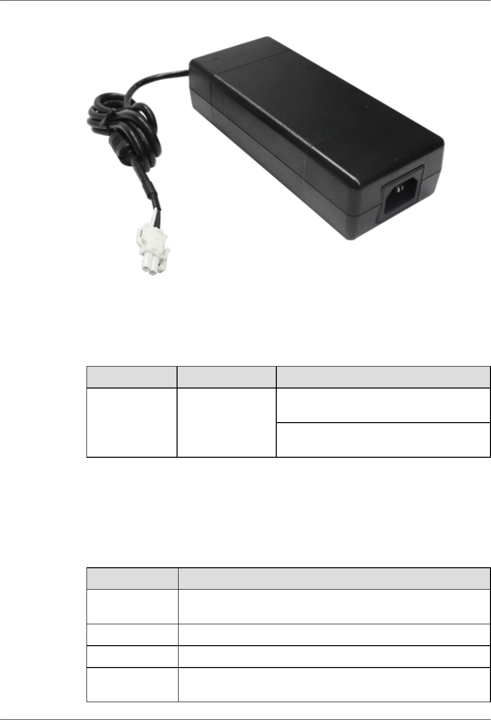
Figure 3-4 Appearance of the HW-100-48AC14D
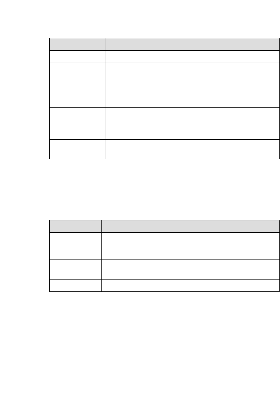
Table 3-3 describes meanings of the indicators.
Table 3-3 Description of the HW-100-48AC14D indicators
Indicator Color Description
Power indicator Blue If the indicator is steady on, the output power is
in the normal range.
If the indicator is off, the power supply unit does
not have output power.
Technical Specifications
Table 3-4 describes the technical specifications of the HW-100-48AC14D.
Table 3-4 Technical specifications of the HW-100-48AC14D
Item Specification
Dimensions (width
x depth x height)
72 mm x 171 mm x 40 mm (2.83 in. x 6.73 in. x 1.57 in.)
Weight 0.65 kg (1.5 lb)
AC input voltage 90 V AC to 264 V AC; typical: 110 V AC/220 V AC
AC input
frequency
47 Hz to 63 Hz; typical: 50 Hz/60 Hz
Huawei AR1200-S&2200-S Series Enterprise Routers
Hardware Description 3 Power Supply Units
Issue 03 (2012-04-20) Huawei Proprietary and Confidential
Copyright © Huawei Technologies Co., Ltd.
21
Item Specification
Rated operating
voltage
100 V AC to 240 V AC; typical: 110 V AC/220 V AC
Rated output
current
2.08 A
Rated output
voltage
48 V
Output power 100 W
Operating
temperature
0°C to 40°C (0°F to 104°F)
Humidity 20% RH to 80% RH
Altitude 4000 m (13123.2 ft.)
Huawei AR1200-S&2200-S Series Enterprise Routers
Hardware Description 3 Power Supply Units
Issue 03 (2012-04-20) Huawei Proprietary and Confidential
Copyright © Huawei Technologies Co., Ltd.
22

4 Heat Dissipation System
About This Chapter
This section describes the heat dissipation system of the AR router.
The fan module of the AR router is described as follows:
lThe fan module of the AR1200-S and AR2220-S is located on the right side in the chassis.
–The fan module dimensions of the AR1200-S are 40 mm [1.58 in.] (width) x 20 mm
[0.79 in.] (depth).
–The fan module dimensions of the AR2220-S are 40 mm [1.58 in.] (width) x 20 mm
[0.79 in.] (depth).
4.1 Heat Dissipation Process
The AR routers heat dissipation system uses fans to create a left-to-right air channel.
Huawei AR1200-S&2200-S Series Enterprise Routers
Hardware Description 4 Heat Dissipation System
Issue 03 (2012-04-20) Huawei Proprietary and Confidential
Copyright © Huawei Technologies Co., Ltd.
23
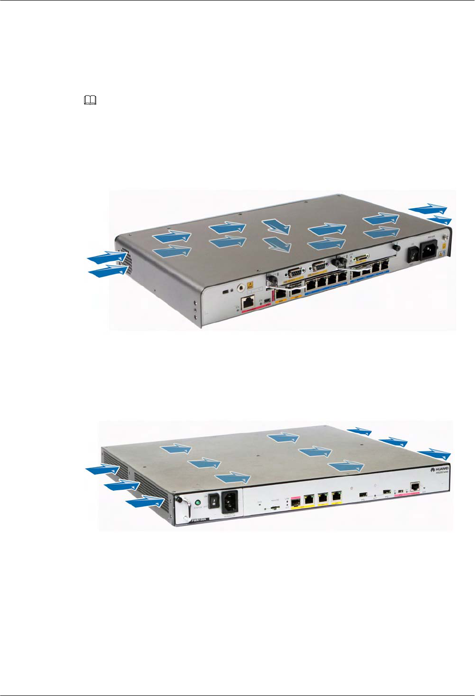
4.1 Heat Dissipation Process
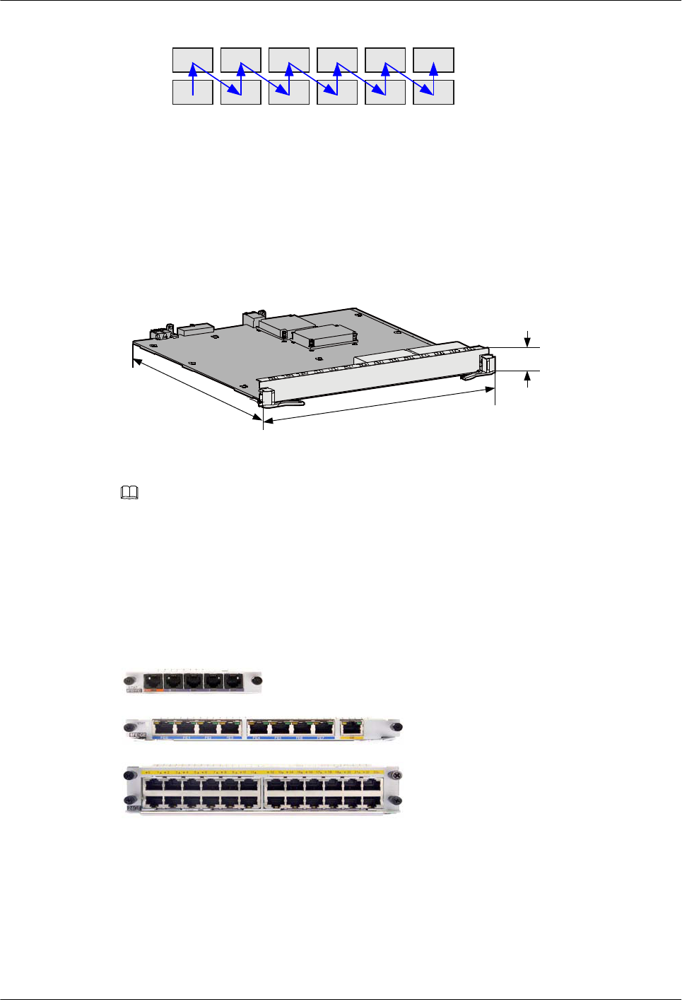
The AR routers heat dissipation system uses fans to create a left-to-right air channel.
NOTE
The heat dissipation system ensures that the AR routers operates at a normal temperature. For temperature
requirements, see 2.5 Physical Specifications.
Figure 4-1 shows air circulation through the AR1200-S chassis.
Figure 4-1 Air circulation through the AR1200-S chassis
Figure 4-2 shows air circulation through the AR2220-S chassis.
Figure 4-2 Air circulation through the AR2220-S chassis
Huawei AR1200-S&2200-S Series Enterprise Routers
Hardware Description 4 Heat Dissipation System
Issue 03 (2012-04-20) Huawei Proprietary and Confidential
Copyright © Huawei Technologies Co., Ltd.
24

5 Cards
About This Chapter
This chapter describes the cards supported by the AR routers.
5.1 Introduction
This section describes the cards supported by the AR routers, including card types, relationships
between cards, the interface numbering scheme, and card dimensions.
5.2 WLAN Subcard
WLAN subcards are Wi-Fi modules.
5.3 Ethernet LAN Interface Card
This section describes the types, functions, applications, appearance, interfaces, and technical
specifications of the Ethernet LAN interface card.
5.4 WAN Interface Card
This section describes the types, functions, applications, appearance, interfaces, and technical
specifications of the WAN interface card.
5.5 Voice Interface Card
This section describes the types, functions, applications, appearance, interfaces, and technical
specifications of the voice interface card.
5.6 xDSL Interface Card
This section describes the types, functions, applications, appearance, interfaces, and technical
specifications of the xDSL/xPON interface card.
Huawei AR1200-S&2200-S Series Enterprise Routers
Hardware Description 5 Cards
Issue 03 (2012-04-20) Huawei Proprietary and Confidential
Copyright © Huawei Technologies Co., Ltd.
25
5.1 Introduction
This section describes the cards supported by the AR routers, including card types, relationships
between cards, the interface numbering scheme, and card dimensions.
5.1.1 Relationships Between Cards
This section describes the relationships between the cards supported by the AR routers.
NOTE
lOn the AR1200, the backplane is at the bottom of the chassis, and cards are installed on the backplane.
lOn the AR2220, the backplane is in the middle of the chassis, cards are installed on the rear side of the
backplane, and a power supply module is installed on the front side of the backplane.
lOn the AR2240, the backplane is in the middle of the chassis, cards are installed on the front and rear
sides of the backplane, and a power supply unit is installed on the front side of the backplane.
lOn the AR3260, the backplane is in the middle of the chassis, cards are installed on the front and rear
sides of the backplane, and a power supply unit is installed on the front side of the backplane.
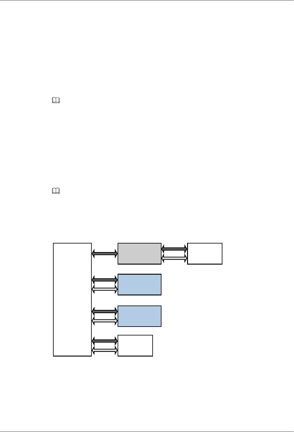
Figure 5-1 and Figure 5-2 illustrates the relationships between the cards supported by the AR
routers.
NOTE
lOn the AR1200–S, the backplane is at the bottom of the chassis, and cards are installed on the backplane.
lOn the AR2220–S, the backplane is in the middle of the chassis, cards are installed on the rear side of
the backplane, and a power supply module is installed on the front side of the backplane.
Figure 5-1 Relationships between cards on the AR1200-S
Service card
Power
Backplane
SRU Fan
Service card
Huawei AR1200-S&2200-S Series Enterprise Routers
Hardware Description 5 Cards
Issue 03 (2012-04-20) Huawei Proprietary and Confidential
Copyright © Huawei Technologies Co., Ltd.
26
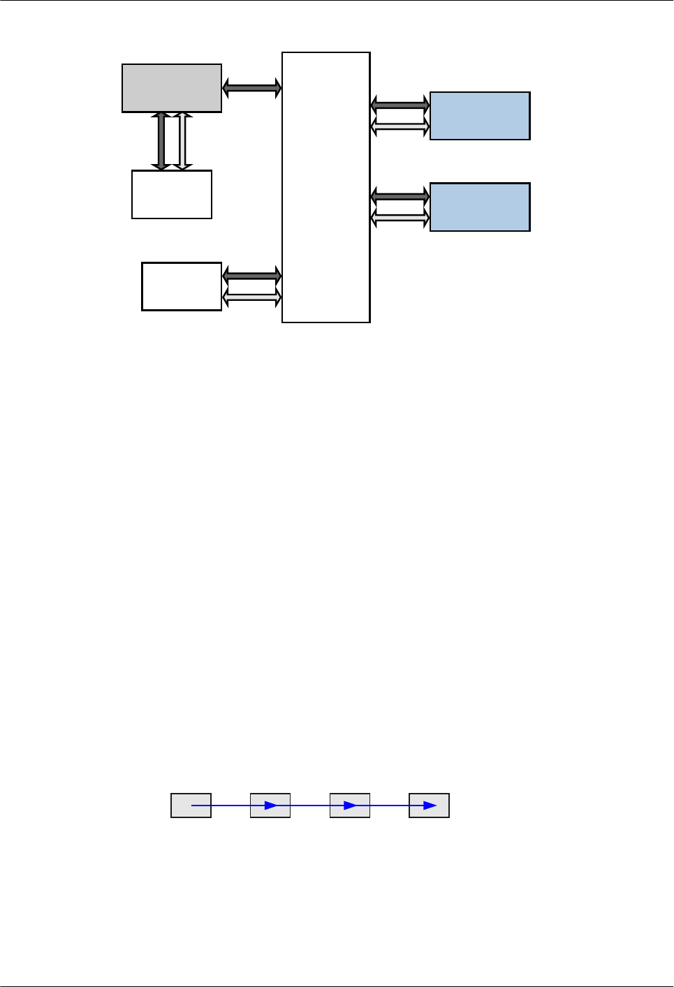
Figure 5-2 Relationships between cards on the AR2220-S
Power
Backplane
SRU
Fan
Service card
Service card
5.1.2 Interface Numbering
This section describes the interface numbering scheme on the AR routers.
On the AR routers, interfaces are numbered in the format of slot ID/subcard ID/interface
sequence number.
lSlot ID
The slot ID specifies the ID of the slot where a card resides.
–The SRU of the AR1200-S and 2220-S is integrated with the chassis, so the slot ID is
fixed as 0.
–When slots need to be combined into one slot, the greater slot ID is used as the new slot
ID. For example, when slot 1 and slot 2 are combined, slot ID 2 is used as the new slot
ID.
lSubcard ID
The subcard ID specifies the ID of a subcard. The cards of AR routers series routers do not
support subcards. Therefore, the subcard ID of the AR routers is fixed as 0.
lInterface sequence number
The interface sequence number indicates the number of each interface on a card.
–There is only one row of interfaces on the interface card. These interfaces are numbered
from left to right starting with 0.
0 1 2 3
–There are two rows of interfaces on the interface card. These interfaces are numbered
from bottom to top and left to right starting with 0.
Huawei AR1200-S&2200-S Series Enterprise Routers
Hardware Description 5 Cards
Issue 03 (2012-04-20) Huawei Proprietary and Confidential
Copyright © Huawei Technologies Co., Ltd.
27
1357911
0246810
5.1.3 Card Dimensions
This section explains the conventions for measuring cards and lists the dimensions of SIC, WSIC,
XSIC card.
Figure 5-3 illustrates the dimensions of a card.
Figure 5-3 Card dimensions description
Width
Depth
Height
NOTE
The card dimensions are defined as follows:
lDepth: the distance between the handle and the end of Printed Circuit Board (PCB)
lWidth: the longest distance between the tops of two handles
lHeight: the height of the ejector lever
Figure 5-4 shows the cards supported by the AR routers and Table 5-1 lists the card dimensions.
Figure 5-4 Card appearances
SIC
WSIC
XSIC
Huawei AR1200-S&2200-S Series Enterprise Routers
Hardware Description 5 Cards
Issue 03 (2012-04-20) Huawei Proprietary and Confidential
Copyright © Huawei Technologies Co., Ltd.
28
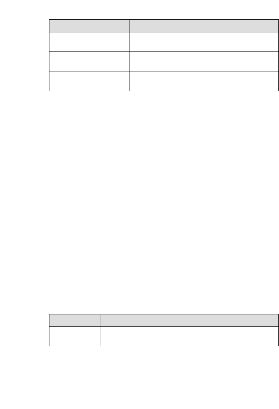
Table 5-1 Card dimensions
Card Type Dimensions (Depth x Width x Height)
SIC card 223.5 mm x 100.1 mm x 19.82 mm (8.8 in. x 3.94 in. x 0.78
in.)
WSIC card 223.5 mm x 201 mm x 19.82 mm (8.8 in. x 7.92 in. x 0.78
in.)
XSIC card 223.5 mm x 201 mm x 40.14 mm (8.8 in. x 7.92 in. x 1.58
in.)
5.2 WLAN Subcard
WLAN subcards are Wi-Fi modules.
5.2.1 Functions and Applications
Functions
lWLAN subcards provide Wi-Fi interfaces. Wi-Fi interfaces comply with IEEE 802.11n,
802.11g, and 802.11b, and each of these interfaces provides a maximum of 300 Mbit/s
transmission rate.
lWLAN subcards provide a high wireless performance and reliability, and large coverage
scope using the multiple-input and multiple-output (MIMO) technology.
lWLAN subcards support 64/128/152-bit WEP encryption, WPA/WPA2 encryption, and
WPA-PSK/WPA2-PSK encryption to provide secure data transmission.
Applications
A WLAN subcard has a dedicated WLAN slot on the AR routers.
5.2.2 Technical Specifications
Table 5-2 describes the technical specifications of the WLAN subcard.
Table 5-2 Technical specifications of the WLAN subcard
Item Specification
Maximum power
consumption
7.24 W
5.3 Ethernet LAN Interface Card
This section describes the types, functions, applications, appearance, interfaces, and technical
specifications of the Ethernet LAN interface card.
Huawei AR1200-S&2200-S Series Enterprise Routers
Hardware Description 5 Cards
Issue 03 (2012-04-20) Huawei Proprietary and Confidential
Copyright © Huawei Technologies Co., Ltd.
29

5.3.1 8FE1GE-8-Port 100BASE-RJ45 and 1-Port 1000BASE-RJ45 L2/
L3 Ethernet Interface Card
The 8FE1GE is the 8-port 100M+1-port 1000M Ethernet electrical interface card (RJ45). It
implements the 9-channel Ethernet Layer 2 and Layer 3 switching functions.
Functions and Applications
Functions
The 8FE1GE provides eight FE electrical interfaces and one GE electrical interface to implement
data access and line-speed switching.
lWhen category 5 twisted pairs (straight-through cables or crossover cables) are used, the
maximum transmission distance is 100 meters.
lWhen category 5 twisted pairs (straight-through cables or crossover cables) are used, 100
Mbit/s line-speed forwarding is supported between the eight FE interfaces.
lThe eight FE interfaces work at 10 Mbit/s or 100 Mbit/s, in auto-sensing mode. The GE
interface works at 10/100/1000 Mbit/s, in auto-sensing mode.
lThese interfaces support the half duplex mode and full duplex mode. The full duplex mode
is most commonly used.
Applications
The 8FE1GE can be installed into the WSIC slots of the AR1200-S and AR2220-S, On the
AR1200-S, two SIC slots are combined into one WSIC slot.
Panel and Interfaces
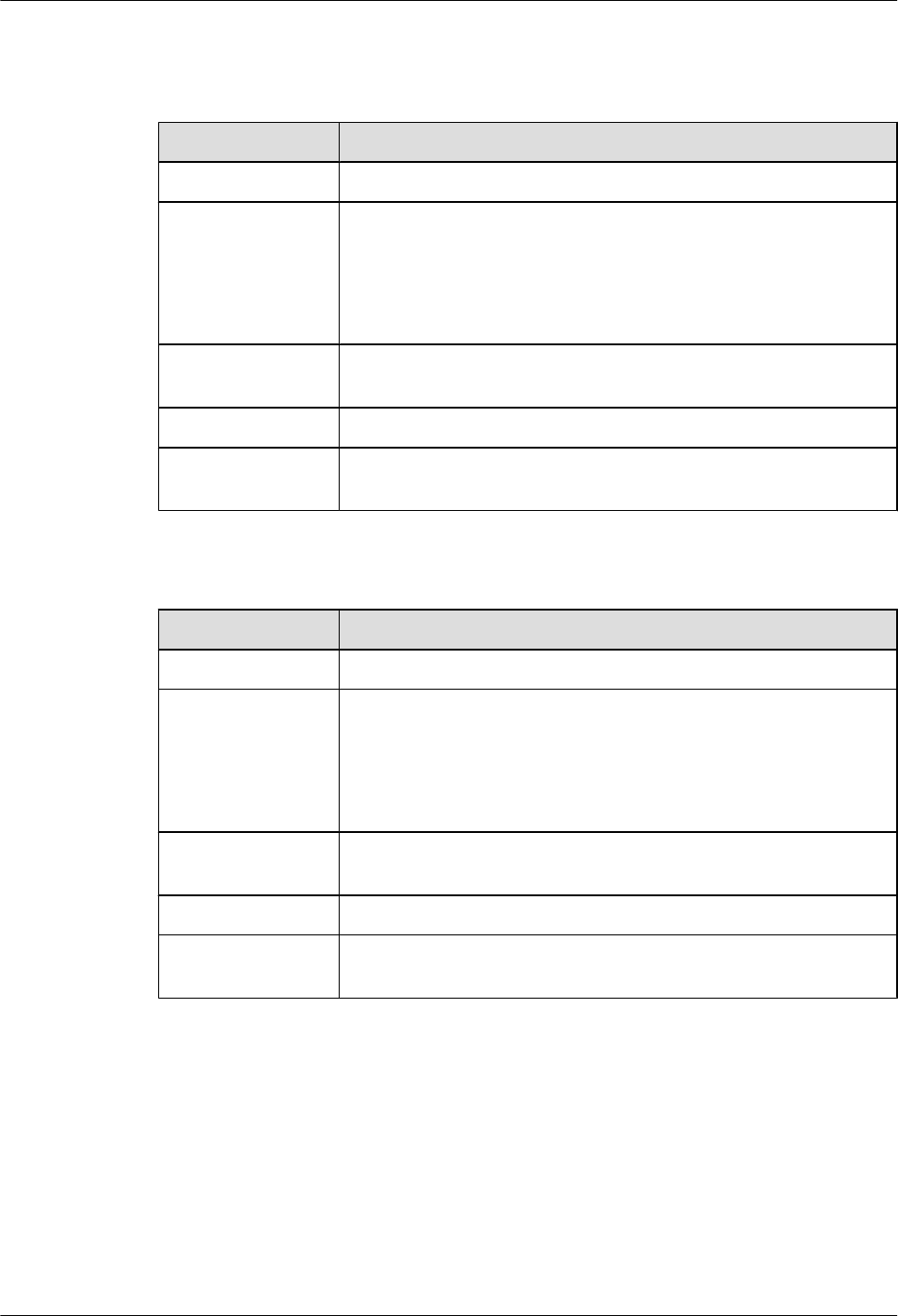
Figure 5-5 shows the appearance of the 8FE1GE.
Figure 5-5 Appearance of the 8FE1GE
3
1
a b
2
Buttons and Indicators on the Panel
Table 5-3 describes the buttons and indicators on the 8FE1GE panel.
Huawei AR1200-S&2200-S Series Enterprise Routers
Hardware Description 5 Cards
Issue 03 (2012-04-20) Huawei Proprietary and Confidential
Copyright © Huawei Technologies Co., Ltd.
30
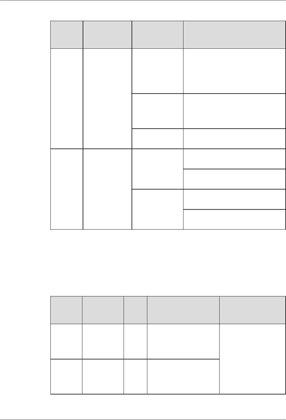
Table 5-3 Buttons and indicators on the 8FE1GE panel
Number
in Figure
5-5
Indicator Color Description
1STAT Green If the indicator blinks once 2s (0.5 Hz),
the system is running properly.
If the indicator blinks once 0.25s (4
Hz), the system is powering on or
restarting.
Red If the indicator is red, a fault that affects
services occurs and cannot be rectified
automatically. The fault needs to be
rectified manually.
Off If the indicator is off, the software is not
running or is being reset.
2 and 3 FE/GE interface
indicators:
lThe LINK
indicator is in
green.
lThe ACT
indicator is in
yellow.
Green If the indicator is steady on, a link has
been established.
If the indicator is off, no link is
established.
Yellow If the indicator is blinking, data is being
transmitted or received.
If the indicator is off, no data is being
transmitted or received.
Interfaces
Table 5-4 describes the types and functions of interfaces on the 8FE1GE.
Table 5-4 Types and functions of interfaces on the 8FE1GE
Letter in
Figure
5-5
Name Quan
tity
Description Cable Type
a 10BASE-TX/
100BASE-
TX electrical
interface
8 The 8FE1GE provides
eight FE electrical
interfaces to transmit and
receive FE services.
6.5 Network Cable
b1000BASE-T
electrical
interface
1 The 8FE1GE provides one
GE electrical interface to
transmit and receive GE
services.
Huawei AR1200-S&2200-S Series Enterprise Routers
Hardware Description 5 Cards
Issue 03 (2012-04-20) Huawei Proprietary and Confidential
Copyright © Huawei Technologies Co., Ltd.
31
Interface Attributes
Table 5-5 Attributes of 10BASE-TX/100BASE-TX electrical interfaces
Item Description
Connector type RJ45
Interface attribute MDI/MDIX
NOTE
lThe interfaces of most network cards are medium dependent interfaces
(MDIs).
lMDIX interfaces are usually used on hubs or LAN switches.
Standards
compliance
IEEE802.3, IEEE802.3u, IEEE802.3ab
Frame format Ethernet_II, Ethernet_SAP, or Ethernet_SNAP
Network layer
protocol
IP
Table 5-6 Attributes of 1000BASE-T electrical interfaces
Item Description
Connector type RJ45
Interface attribute MDI/MDIX
NOTE
lThe interfaces of most network cards are medium dependent interfaces
(MDIs).
lMDIX interfaces are usually used on hubs or LAN switches.
Standards
compliance
IEEE802.3, IEEE802.3u, IEEE802.3ab
Frame format Ethernet_II, Ethernet_SAP, or Ethernet_SNAP
Network layer
protocol
IP
Technical Specifications
Table 5-7 describes the technical specifications of the 8FE1GE.
Huawei AR1200-S&2200-S Series Enterprise Routers
Hardware Description 5 Cards
Issue 03 (2012-04-20) Huawei Proprietary and Confidential
Copyright © Huawei Technologies Co., Ltd.
32

Table 5-7 Technical specifications of the 8FE1GE
Item Specification
Dimensions
(depth x width x
height)
223.5 mm x 201 mm x 19.82 mm (8.8 in. x 7.92 in. x 0.78 in.)
Maximum power
consumption
12.036 W
Weight 0.6 kg (1.33 lb)
5.3.2 24GE-24-Port 1000BASE-RJ45 L2/L3 Ethernet Interface Card
The 24GE is the 24-port 1000M Ethernet electrical interface card (RJ45). It implements the 24-
channel Ethernet Layer 2 and Layer 3 switching functions.
Functions and Applications
Functions
The 24GE provides 24 GE electrical interfaces to implement data access and line-speed
switching.
lWhen category 5 twisted pairs (straight-through cables or crossover cables) are used, the
maximum transmission distance is 100 meters.
lWhen category 5 twisted pairs (straight-through cables or crossover cables) are used, 1000
Mbit/s line-speed forwarding is supported between the 24 GE interfaces.
lThese interfaces work in 10/100/1000 Mbit/s auto-sensing mode.
lThese interfaces support the half duplex mode and full duplex mode. The full duplex mode
is most commonly used.
Applications
The 24GE can be installed into the XSIC slot on the AR2220-S. On the AR2220-S, two WSIC
slots are combined into one XSIC slot.
Panel and Interfaces
Figure 5-6 shows the appearance of the 24GE.
Huawei AR1200-S&2200-S Series Enterprise Routers
Hardware Description 5 Cards
Issue 03 (2012-04-20) Huawei Proprietary and Confidential
Copyright © Huawei Technologies Co., Ltd.
33
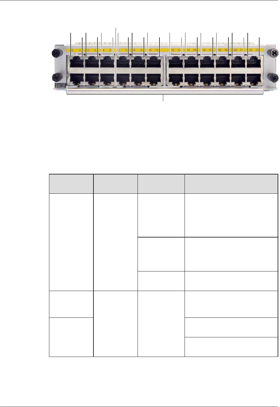
Figure 5-6 Appearance of the 24GE
1
a
23
2323232323232323232323
Buttons and Indicators on the Panel
Table 5-8 describes the buttons and indicators on the 24GE panel.
Table 5-8 Buttons and indicators on the 24GE panel
Number in
Figure 5-6
Indicator Color Description
1STAT Green If the indicator blinks once 2s (0.5
Hz), the system is running properly.
If the indicator blinks once 0.25s (4
Hz), the system is powering on or
restarting.
Red If the indicator is red, a fault that
affects services occurs and cannot be
rectified automatically. The fault
needs to be rectified manually.
Off If the indicator is off, the software is
not running or is being reset.
2: indicators of
interfaces in the
second row
LINK Green If the indicator is steady on, a link
has been established.
3: indicators of
interfaces in the
first row
If the indicator is blinking, data is
being transmitted or received.
If the indicator is off, the link is not
connected.
Interfaces
Table 5-9 describes the types and functions of interfaces on the 24GE.
Huawei AR1200-S&2200-S Series Enterprise Routers
Hardware Description 5 Cards
Issue 03 (2012-04-20) Huawei Proprietary and Confidential
Copyright © Huawei Technologies Co., Ltd.
34
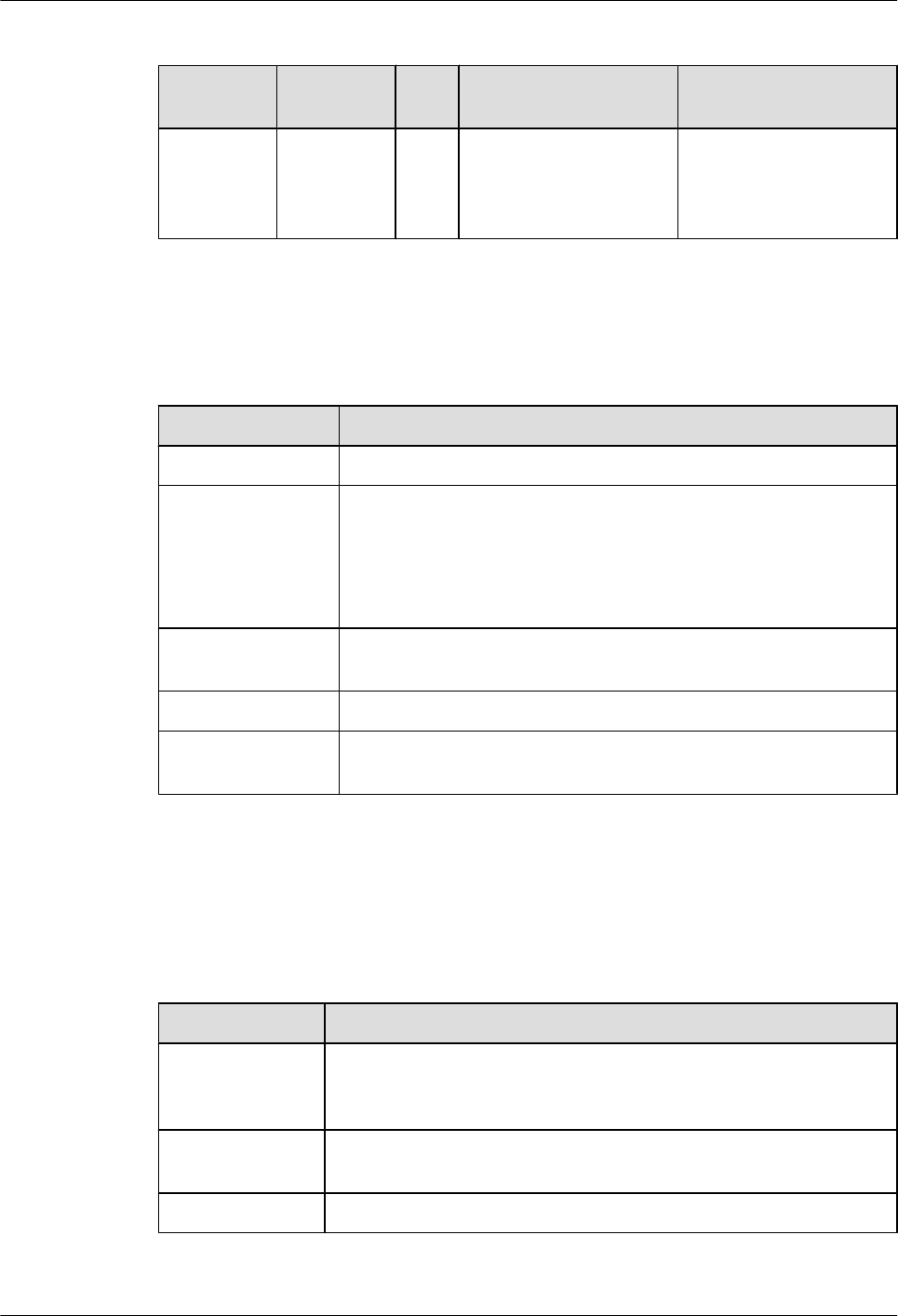
Table 5-9 Types and functions of interfaces on the 24GE
Letter in
Figure 5-6
Name Qua
ntity
Description Cable Type
a 1000BASE-
T electrical
interface
24 The 24GE provides 24
GE electrical interfaces to
transmit and receive GE
services.
6.5 Network Cable
Interface Attributes
Table 5-10 Attributes of 1000BASE-T electrical interfaces
Item Description
Connector type RJ45
Interface attribute MDI/MDIX
NOTE
lThe interfaces of most network cards are medium dependent interfaces
(MDIs).
lMDIX interfaces are usually used on hubs or LAN switches.
Standards
compliance
IEEE802.3, IEEE802.3u, IEEE802.3ab
Frame format Ethernet_II, Ethernet_SAP, or Ethernet_SNAP
Network layer
protocol
IP
Technical Specifications
Table 5-11 describes the technical specifications of the 24GE.
Table 5-11 Technical specifications of the 24GE
Item Specification
Dimensions
(depth x width x
height)
223.50 mm x 201.00 mm x 40.14 mm (8.8 in. x 7.92 in. x 1.58 in.)
Maximum power
consumption
25 W
Weight 0.85 kg (1.88 lb)
Huawei AR1200-S&2200-S Series Enterprise Routers
Hardware Description 5 Cards
Issue 03 (2012-04-20) Huawei Proprietary and Confidential
Copyright © Huawei Technologies Co., Ltd.
35

5.4 WAN Interface Card
This section describes the types, functions, applications, appearance, interfaces, and technical
specifications of the WAN interface card.
5.4.1 1GEC (1-Port-GE Combo WAN Interface Card)
1GEC is a 1-port 1000M Ethernet optical and electrical Combo interface card (RJ45, SFP). Only
one of the optical interface and electrical interface can be used at a time.
1GEC stands for:
l1: one interface
lGE: 1000M Ethernet
lC: Combo interface
Functions and Applications
Functions
The 1GEC provides one GE optical and electrical Combo interface to implement data access
and line-speed switching.
lThe Combo interface sends, receives, and processes GE data traffic.
lThe electrical interface works at 10/100/1000 Mbit/s in auto-sensing mode.
lThe optical interface works at 100/1000 Mbit/s in auto-sensing mode.
Applications
The 1GEC is installed into the SIC slot of the AR1200-S and AR2220-S.
Panel and Interfaces
Figure 5-7 shows the appearance of the 1GEC panel.
Figure 5-7 Appearance of the 1GEC panel
12 3 4 5
a b
Buttons and Indicators on the Panel
Table 5-12 describes the buttons and indicators on the 1GEC panel.
Huawei AR1200-S&2200-S Series Enterprise Routers
Hardware Description 5 Cards
Issue 03 (2012-04-20) Huawei Proprietary and Confidential
Copyright © Huawei Technologies Co., Ltd.
36
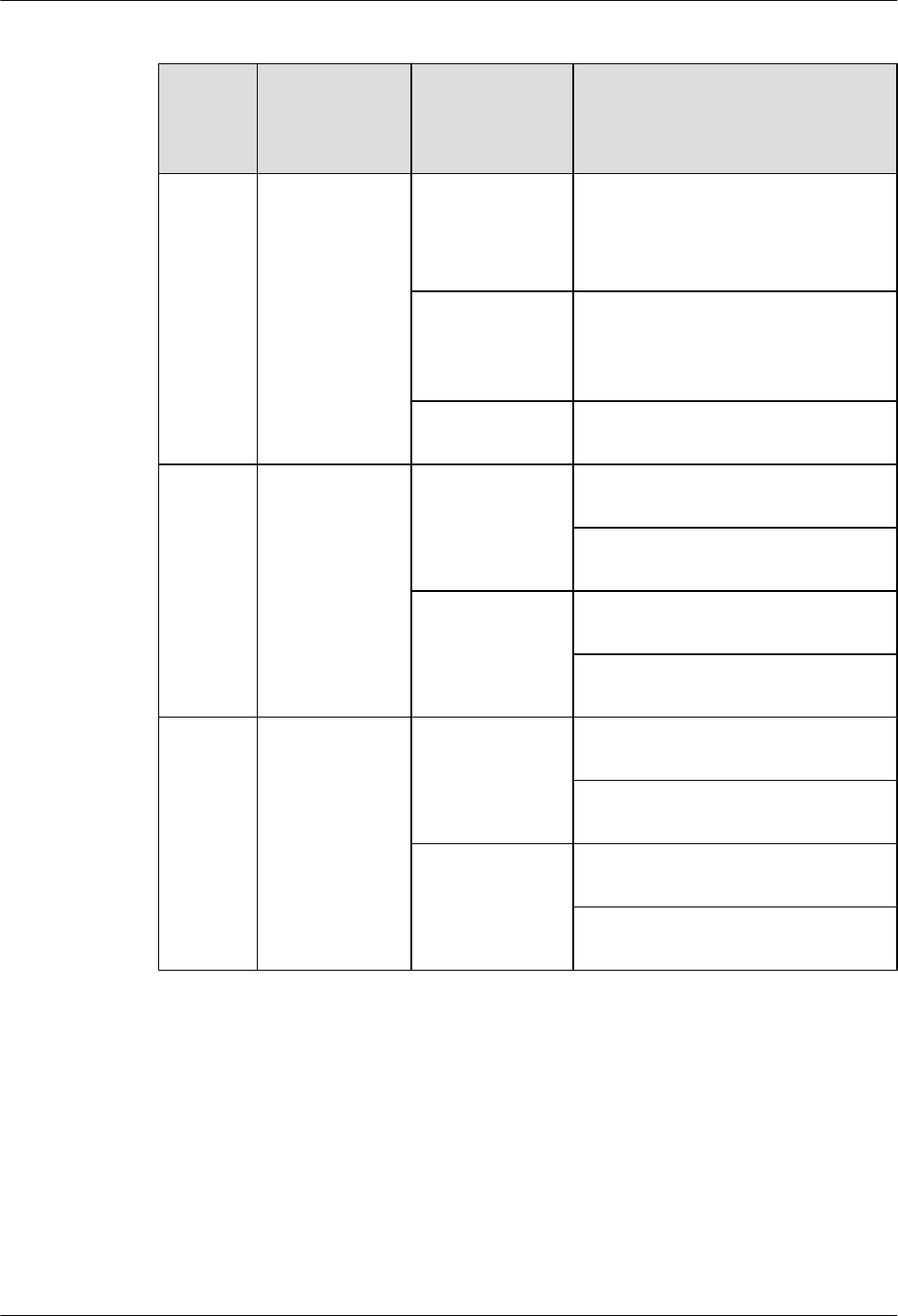
Table 5-12 Buttons and indicators on the 1GEC panel
Number
in
Figure
5-7
Indicator Color Description
1STAT Green If the indicator blinks once 2s (0.5 Hz),
the system is running properly.
If the indicator blinks once 0.25s (4 Hz),
the system is powering on or restarting.
Red If the indicator is red, a fault that affects
services occurs and cannot be rectified
automatically. The fault needs to be
rectified manually.
Off If the indicator is off, the software is not
running or is being reset.
2 and 3 GE interface
indicators:
lThe LINK
indicator is in
green.
lThe ACT
indicator is in
yellow.
Green If the indicator is steady on, a link has
been established.
If the indicator is off, no link is
established.
Yellow If the indicator is blinking, data is being
transmitted or received.
If the indicator is off, no data is being
transmitted or received.
4 and 5 SFP interface
indicators:
lThe LINK
indicator is in
green.
lThe ACT
indicator is in
yellow.
Green If the indicator is steady on, a link has
been established.
If the indicator is off, no link is
established.
Yellow If the indicator is blinking, data is being
transmitted or received.
If the indicator is off, no data is being
transmitted or received.
Interfaces
Table 5-13 describes the types and functions of interface on the 1GEC.
Huawei AR1200-S&2200-S Series Enterprise Routers
Hardware Description 5 Cards
Issue 03 (2012-04-20) Huawei Proprietary and Confidential
Copyright © Huawei Technologies Co., Ltd.
37
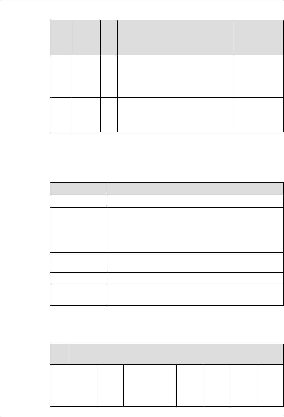
Table 5-13 Types and functions of the interface on the 1GEC
Lette
r in
Figur
e 5-7
Name Qu
ant
ity
Description Cable Type
a 1000BA
SE-T
electrica
l
interface
1 The 1GEC provides one GE electrical
interface to transmit and receive GE services.
NOTE
Only one of the optical interface and electrical
interface can be used at a time.
6.5 Network
Cable
b 1000BA
SE-X
optical
interface
1 The 1GEC provides one GE optical interface
to transmit and receive GE services.
6.6 Optical
Fiber
Interface Attributes
Table 5-14 Attributes of 1000BASE-T electrical interfaces
Item Description
Connector type RJ45
Interface attribute MDI/MDIX
NOTE
lThe interfaces of most network cards are medium dependent interfaces
(MDIs).
lMDIX interfaces are usually used on hubs or LAN switches.
Standards
compliance
IEEE802.3, IEEE802.3u, IEEE802.3ab
Frame format Ethernet_II, Ethernet_SAP, or Ethernet_SNAP
Network layer
protocol
IP
Table 5-15 Attributes of the SFP optical module (100/1000 Mbit/s) supported by the GE optical
interface
Attri
bute
Description
Tran
smiss
ion
dista
nce
500 m 10 km 10 km (single-
mode bidirectional
fiber)
40 km 40 km 80 km 100 km
Huawei AR1200-S&2200-S Series Enterprise Routers
Hardware Description 5 Cards
Issue 03 (2012-04-20) Huawei Proprietary and Confidential
Copyright © Huawei Technologies Co., Ltd.
38
Attri
bute
Description
Cent
er
wave
lengt
h
850 nm 1310
nm
Tx:
1310
nm
Rx:
1490
nm
Tx:
1490
nm
Rx:
1310
nm
1310
nm
1550
nm
1550
nm
1550
nm
Tran
smitt
ing
powe
r
-9.5
dBm to
-2.5
dBm
-9.0
dBm to
-3.0
dBm
-9.0
dBm to
-3.0
dBm
-9.0
dBm to
-3.0
dBm
-5.0
dBm to
0 dBm
-5.0
dBm to
0 dBm
-2.0
dBm to
5.0
dBm
0 dBm
to 5
dBm
Rece
iver
sensi
tivity
-17.0
dBm
-20.0
dBm
-19.5
dBm
-19.5
dBm
-23
dBm
-22
dBm
-23.0
dBm
-30.0
dBm
Over
load
optic
al
powe
r
0 dBm -3.0
dBm
-3.0
dBm
-3.0
dBm
-3.0
dBm
-3.0
dBm
-3.0
dBm
-9.0
dBm
Extin
ction
ratio
9 dB 9 dB 6 dB 6 dB 9 dB 8.5 dB 9 dB 8 dB
Fiber
type
Multi-
mode
Single-mode
Technical Specifications
Table 5-16 describes the technical specifications of the 1GEC.
Table 5-16 Technical specifications of the 1GEC
Item Specification
Dimensions
(depth x width x
height)
223.5 mm x 100.1 mm x 19.82 mm (8.8 in. x 3.94 in. x 0.78 in.)
Maximum power
consumption
2.28 W
Weight 0.25 kg (0.55 lb)
Huawei AR1200-S&2200-S Series Enterprise Routers
Hardware Description 5 Cards
Issue 03 (2012-04-20) Huawei Proprietary and Confidential
Copyright © Huawei Technologies Co., Ltd.
39
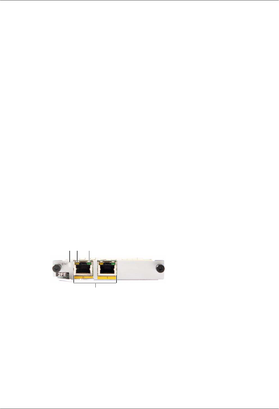
5.4.2 2FE-2-Port-FE WAN Interface Card
The 2FE is the 2-port 100M Ethernet electrical interface card (RJ45).
Functions and Applications
Functions
The 2FE provides two FE electrical interfaces to implement data access and line-speed
switching.
lWhen category 5 twisted pairs (straight-through cables or crossover cables) are used, the
maximum transmission distance is 100 meters.
lTwo FE electrical interfaces can be bound to function as an upstream interface at the line
rate of 200 Mbit/s.
lThe two FE interfaces work in 10/100 Mbit/s auto-sensing mode.
lThese interfaces support the half duplex mode and full duplex mode. The full duplex mode
is most commonly used.
Applications
The 2FE can be installed into the SIC slot of the AR1200-S, AR2220-S.
Panel and Interfaces
Figure 5-8 shows the appearance of the 2FE.
Figure 5-8 Appearance of the 2FE
12 3
a
Buttons and Indicators on the Panel
Table 5-17 describes the buttons and indicators on the 2FE panel.
Huawei AR1200-S&2200-S Series Enterprise Routers
Hardware Description 5 Cards
Issue 03 (2012-04-20) Huawei Proprietary and Confidential
Copyright © Huawei Technologies Co., Ltd.
40
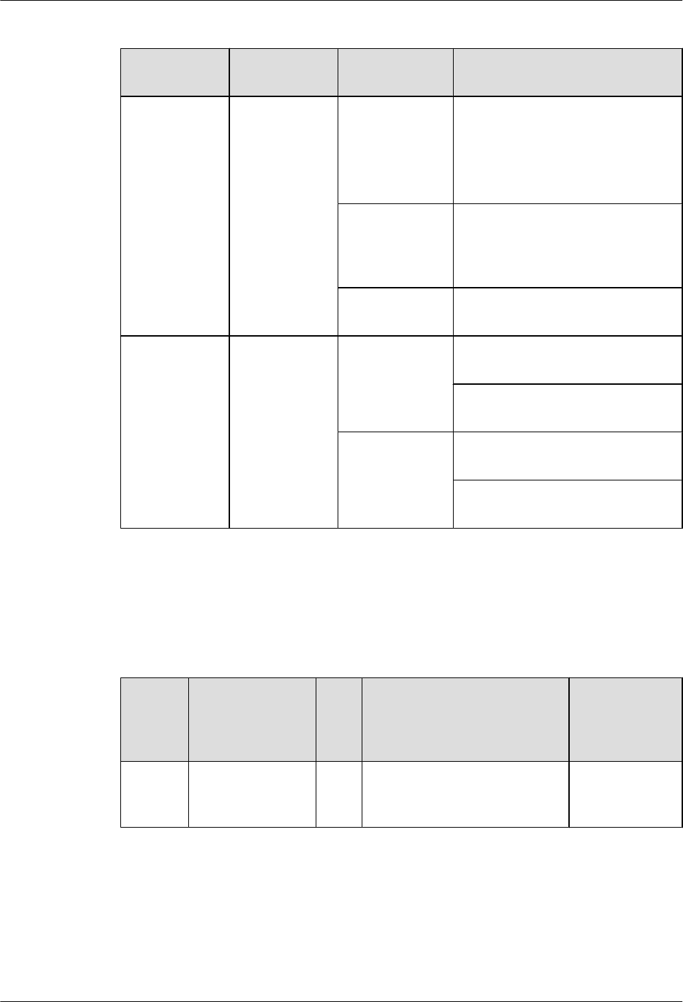
Table 5-17 Buttons and indicators on the 2FE panel
Number in
Figure 5-8
Indicator Color Description
1STAT Green If the indicator blinks once 2s (0.5
Hz), the system is running properly.
If the indicator blinks once 0.25s (4
Hz), the system is powering on or
restarting.
Red If the indicator is red, a fault that
affects services occurs and cannot be
rectified automatically. The fault
needs to be rectified manually.
Off If the indicator is off, the software is
not running or is being reset.
2 and 3 FE interface
indicators:
lThe LINK
indicator is
in green.
lThe ACT
indicator is
in yellow.
Green If the indicator is steady on, a link
has been established.
If the indicator is off, no link is
established.
Yellow If the indicator is blinking, data is
being transmitted or received.
If the indicator is off, no data is being
transmitted or received.
Interfaces
Table 5-18 describes the types and functions of interfaces on the 2FE.
Table 5-18 Types and functions of interfaces on the 2FE
Letter
in
Figure
5-8
Name Qua
ntit
y
Description Cable Type
a FE electrical
interface
2 The 2FE provides two FE
electrical interfaces to transmit
and receive FE services.
6.5 Network
Cable
Huawei AR1200-S&2200-S Series Enterprise Routers
Hardware Description 5 Cards
Issue 03 (2012-04-20) Huawei Proprietary and Confidential
Copyright © Huawei Technologies Co., Ltd.
41
Interface Attributes
Table 5-19 Attributes of 10BASE-TX/100BASE-TX electrical interfaces
Item Description
Connector type RJ45
Interface attribute MDI/MDIX
NOTE
lThe interfaces of most network cards are medium dependent interfaces
(MDIs).
lMDIX interfaces are usually used on hubs or LAN switches.
Standards
compliance
IEEE802.3, IEEE802.3u, IEEE802.3ab
Frame format Ethernet_II, Ethernet_SAP, or Ethernet_SNAP
Network layer
protocol
IP
Technical Specifications
Table 5-20 describes the technical specifications of the 2FE.
Table 5-20 Technical specifications of the 2FE
Item Specification
Dimensions
(depth x width x
height)
223.5 mm x 100.1 mm x 19.82 mm (8.8 in. x 3.94 in. x 0.78 in.)
Maximum power
consumption
3.01 W
Weight 0.3 kg (0.66 lb)
5.4.3 1E1T1-M/2E1T1-M-1/2 Port-Channelized E1/T1/PRI/VE1
Multifunctional Interface Card
The 1E1T1-M/2E1T1-M is the E1/T1/PRI/VE1 processing unit on the AR routers and provides
one or two E1/T1/PRI/VE1 interfaces. Primary Rate Interface (PRI) indicates ISDN primary
rate interfaces.
Huawei AR1200-S&2200-S Series Enterprise Routers
Hardware Description 5 Cards
Issue 03 (2012-04-20) Huawei Proprietary and Confidential
Copyright © Huawei Technologies Co., Ltd.
42
NOTE
l1/2: indicates one or two interfaces.
lE1: indicates E1 interfaces.
lT1: indicates T1 interfaces.
lM: indicates multiflex trunks.
lVE1: indicates voice E1 interfaces.
Table 5-21 lists the number of interfaces on the 1E1T1-M and 2E1T1-M.
Table 5-21 Number of interfaces on the 1E1T1-M and 2E1T1-M
Card Name Quantity of Interfaces
1E1T1-M 1
2E1T1-M 2
2E1T1-M cards have two types: SIC and WSIC. Table 5-22 lists the slots where the SIC card
and WSIC card are installed.
Table 5-22 Slots of 2E1T1-M SIC and WSIC cards
Card Slot
2E1T1-M (SIC) SIC slot
2E1T1-M (WSIC) WSIC slot or XSIC slot
NOTE
In an XSIC slot, the WSIC card is installed in the lower part
of the slot. The WSIC card uses the XSIC slot ID as its own
slot ID.
Functions and Applications
Functions
The 1E1T1-M/2E1T1-M provides the following functions:
lSends, receives, and processes E1/T1 data traffic.
lProvides CE1/T1 access.
lProvides the ISDN PRI function.
Applications
1E1T1-M/2E1T1-M(SIC) can be installed into the SIC slot of the AR1200-S and AR2220-S.
2E1T1-M(WSIC) is installed in a WSIC or XSIC slot on the AR2220-S.
Huawei AR1200-S&2200-S Series Enterprise Routers
Hardware Description 5 Cards
Issue 03 (2012-04-20) Huawei Proprietary and Confidential
Copyright © Huawei Technologies Co., Ltd.
43
Panel and Interfaces
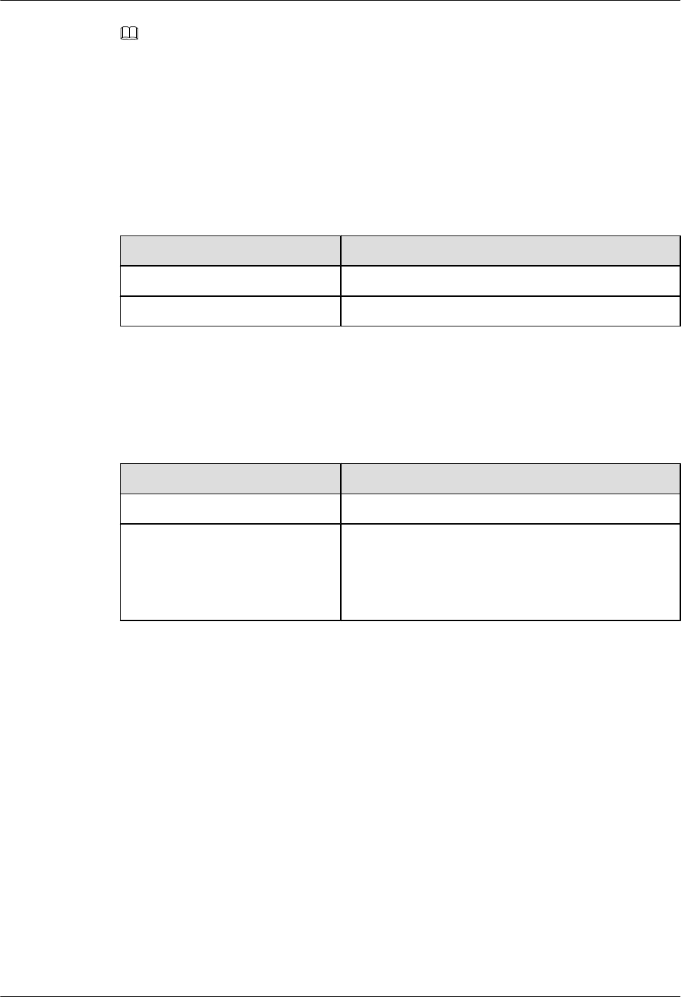
Figure 5-9 shows the appearance of the 1E1T1-M.
Figure 5-9 Appearance of the 1E1T1-M
1 2
a
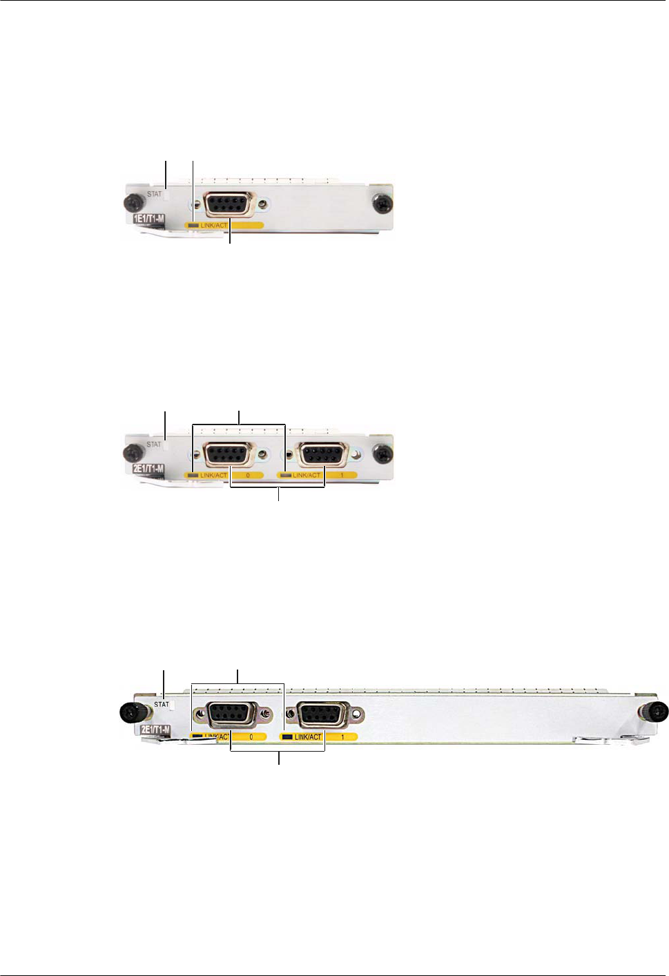
Figure 5-10 shows the appearance of the 2E1T1-M (SIC).
Figure 5-10 Appearance of the 2E1T1-M (SIC)
1
a
2
Figure 5-11 shows the appearance of the 2E1T1-M (WSIC).
Figure 5-11 Appearance of the 2E1T1-M (WSIC)
1
a
2
Buttons and Indicators on the Panel
Table 5-23 describes the buttons and indicators on the 1E1T1-M/2E1T1-M panel.
Huawei AR1200-S&2200-S Series Enterprise Routers
Hardware Description 5 Cards
Issue 03 (2012-04-20) Huawei Proprietary and Confidential
Copyright © Huawei Technologies Co., Ltd.
44
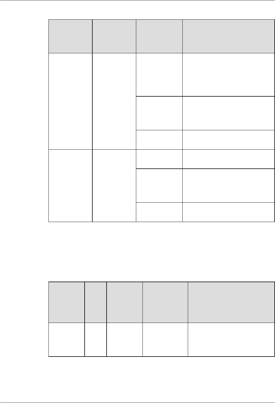
Table 5-23 Buttons and indicators on the 1E1T1-M/2E1T1-M panel
Number in
Figure 5-9,
Figure 5-10,
Figure 5-11
Indicator Color Description
1STAT Green If the indicator blinks once 2s (0.5
Hz), the system is running properly.
If the indicator blinks once 0.25s (4
Hz), the system is powering on or
restarting.
Red If the indicator is red, a fault that
affects services occurs and cannot be
rectified automatically. The fault
needs to be rectified manually.
Off If the indicator is off, the software is
not running or is being reset.
2 LINK/ACT Green If the indicator is steady on, a link
has been established.
Yellow (The
indicator is in
green and blinks
red.)
If the indicator is in green and blinks
red, data is being transmitted or
received.
Off If the indicator is off, there is no
connection.
Interfaces
Table 5-24 describes the types and functions of interfaces on the 1E1T1-M/2E1T1-M.
Table 5-24 Types and functions of interfaces on the 1E1T1-M/2E1T1-M
Letter in
Figure 5-9,
Figure
5-10,
Figure 5-11
Nam
e
Quantity Description Cable Type
a DB9 1E1T1-M: 1
2E1T1-M: 2
75-ohm or 120-
ohm E1 cable or
100-ohm T1
cable
6.7 E1/T1 Trunk Cables
Huawei AR1200-S&2200-S Series Enterprise Routers
Hardware Description 5 Cards
Issue 03 (2012-04-20) Huawei Proprietary and Confidential
Copyright © Huawei Technologies Co., Ltd.
45
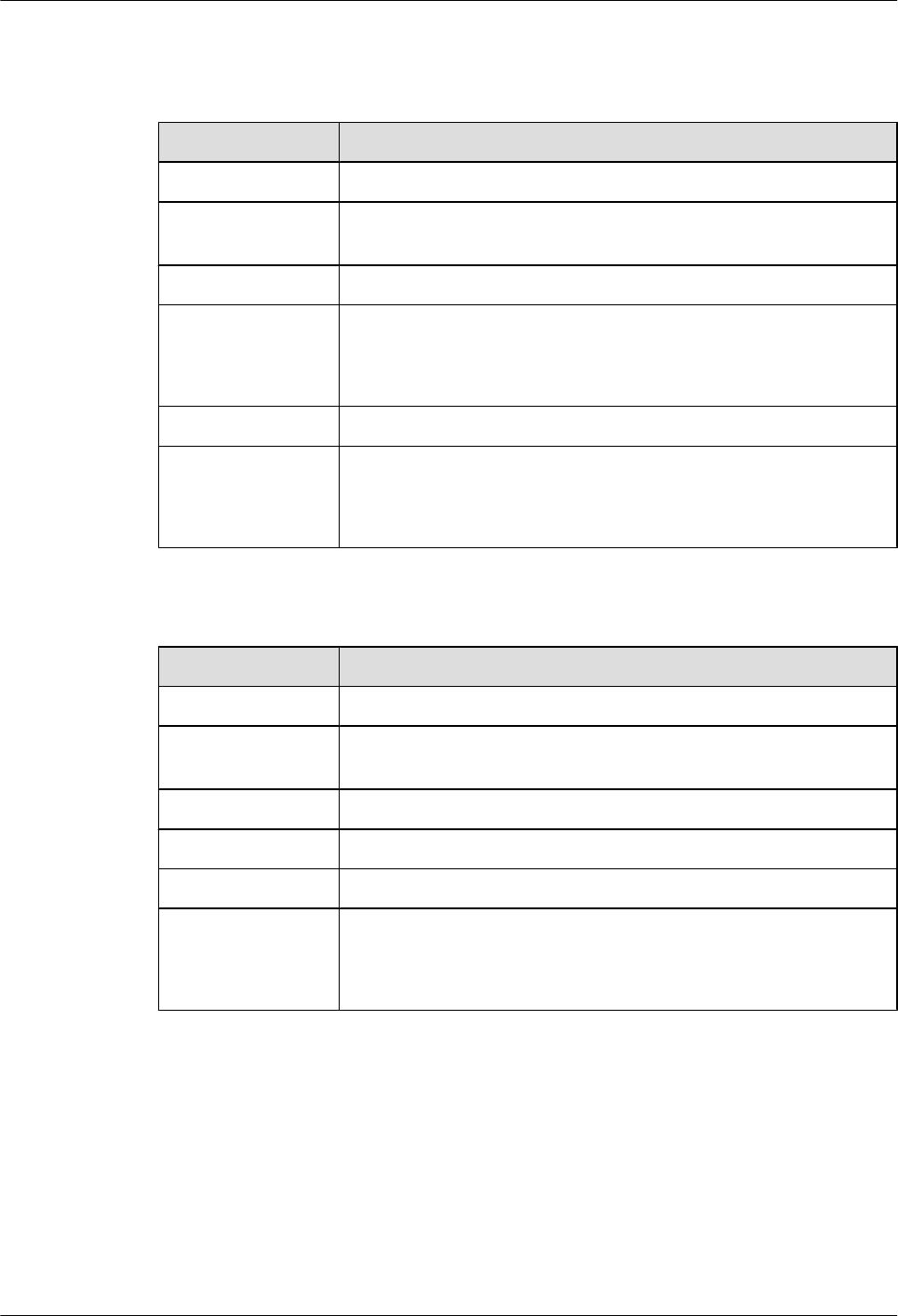
Interface Attributes
Table 5-25 Attributes of channelized E1 interfaces
Attribute Description
Connector type DB9
Standards
compliance
G.703 or G.704
Transmission rate 2.048 Mbit/s
Cable type E1 75-ohm unbalanced coaxial cable
E1 120-ohm balanced twisted pair cable
E1 trunk cable extension
Working mode CE1, ISDN PRI, or VE1
Function Backup
Terminal access
ISDN PRI
Table 5-26 Attributes of channelized T1 interfaces
Attribute Description
Connector type DB9
Standards
compliance
G.703 or G.704
Transmission rate 1.544 Mbit/s
Cable type T1 100-ohm coaxial cable
Working mode CT1, ISDN PRI, or VT1
Function Backup
Terminal access
ISDN PRI
Technical Specifications
Table 5-27 describes the technical specifications of the 1E1T1-M/2E1T1-M.
Huawei AR1200-S&2200-S Series Enterprise Routers
Hardware Description 5 Cards
Issue 03 (2012-04-20) Huawei Proprietary and Confidential
Copyright © Huawei Technologies Co., Ltd.
46
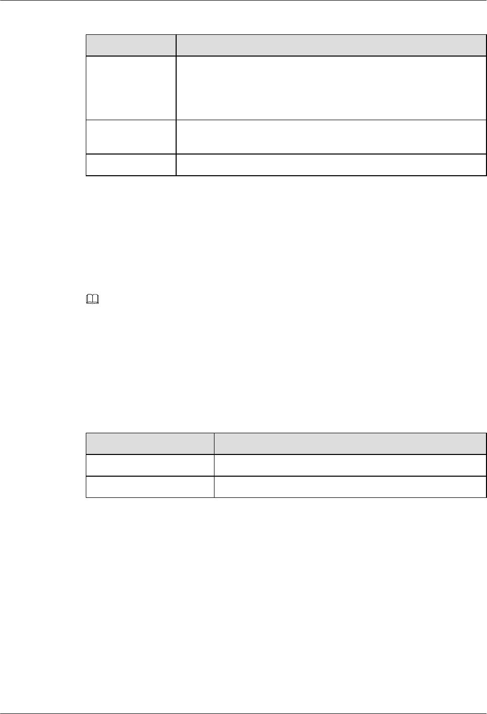
Table 5-27 Technical specifications of the 1E1T1-M/2E1T1-M
Item Specification
Dimensions
(depth x width x
height)
1E1T1-M/2E1T1-M (SIC): 223.5 mm x 100.1 mm x 19.82 mm (8.8 in.
x 3.94 in. x 0.78 in.)
2E1T1-M (WSIC): 223.5 mm x 201 mm x 19.82 mm (8.8 in. x 7.92 in.
x 0.78 in.)
Maximum power
consumption
7 W
Weight 0.3 kg (0.66 lb)
5.4.4 1E1T1-F/2E1T1-F (1/2-Port-Fractional Channelized E1/T1
WAN Interface Card)
The 1E1T1-F/2E1T1-F is the E1/T1 processing unit on the AR routers and provides one or two
E1/T1 interfaces.
NOTE
1E1T1-F/2E1T1-F stands for:
l1/2: one or two interfaces
lE1: E1 interface
lT1: T1 interface
lF: fractional E1
Table 5-28 lists the number of interfaces on the 1E1T1-F and 2E1T1-F.
Table 5-28 Number of interfaces on the 1E1T1-F and 2E1T1-F
Card Name Quantity of Interfaces
1E1T1-F 1
2E1T1-F 2
Functions and Applications
Functions
The 1E1T1-F/2E1T1-F sends, receives, and processes E1/T1 data traffic. Table 5-29 describes
the differences in functions provided by the 1E1T1-F/2E1T1-F and 1E1T1-M/2E1T1-M.
Huawei AR1200-S&2200-S Series Enterprise Routers
Hardware Description 5 Cards
Issue 03 (2012-04-20) Huawei Proprietary and Confidential
Copyright © Huawei Technologies Co., Ltd.
47
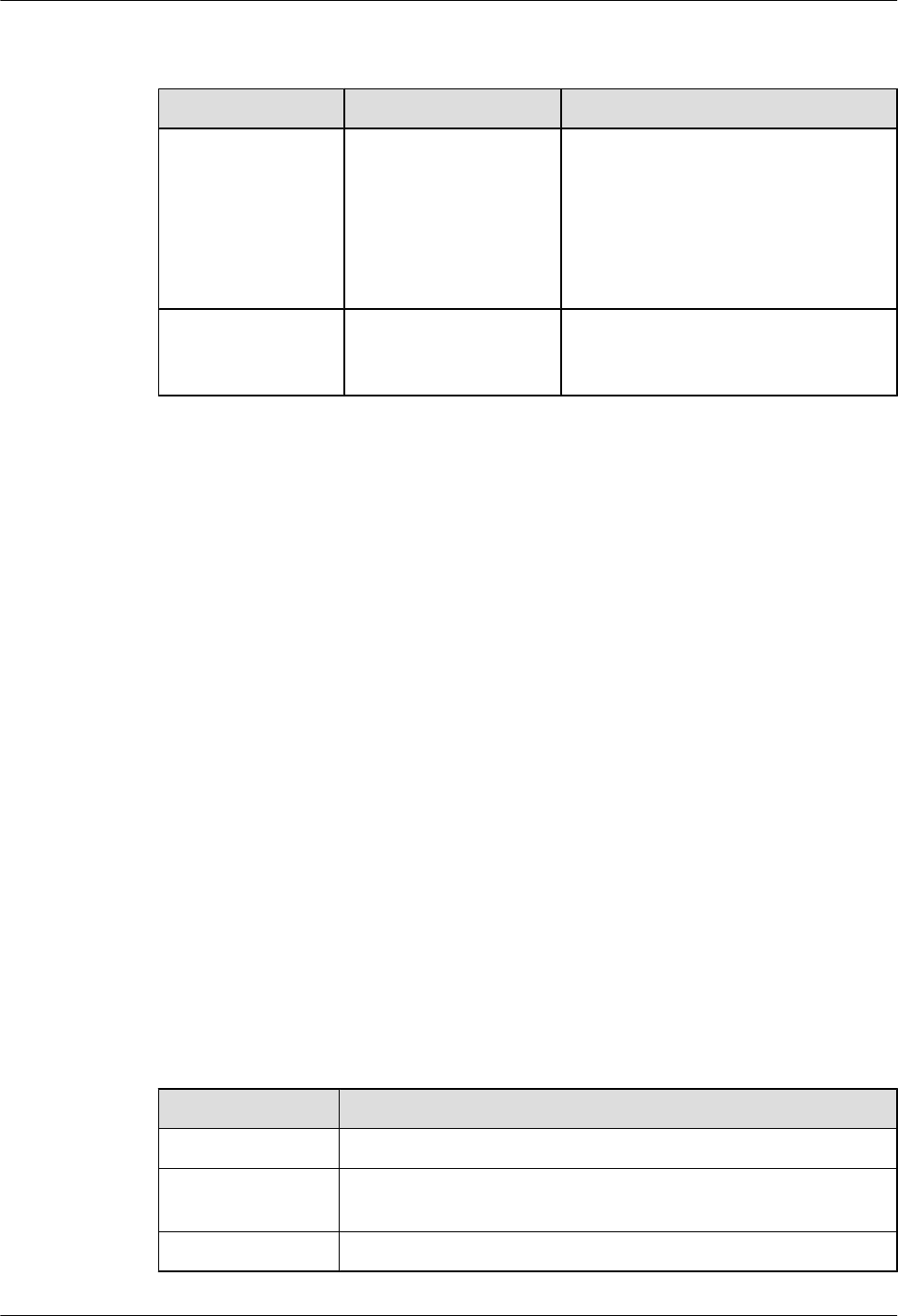
Table 5-29 Differences in functions provided by the 1E1T1-F/2E1T1-F and 1E1T1-M/2E1T1-
M
Card Name Fractional E1 Mode Whether to Support the PRI Mode
1E1T1-F/2E1T1-F Timeslots of an E1/T1
interface can only be
bundled into one channel
at a rate of n x 64 kbit/s (n
specifies the number of
bundled timeslots and
ranges from 1 to 31).
No
1E1T1-M/2E1T1-M Timeslots of an E1/T1
interface can be bundled
into multiple channels.
Yes
Applications
The 1E1T1-F/2E1T1-F is installed into the SIC slot of the AR1200-S and AR2220-S.
Panel and Interfaces
The 1E1T1-F and 1E1T1-M panels are identical except for having different silkscreens. Figure
5-9 shows the appearance of the 1E1T1-F panel.
The 2E1T1-F and 2E1T1-M panels are identical except for having different silkscreens. Figure
5-10 shows the appearance of the 2E1T1-F panel.
Buttons and Indicators on the Panel
Table 5-23 describes the buttons and indicators on the 1E1T1-F/2E1T1-F panel.
Interfaces
Table 5-24 describes the types and functions of interfaces on the 1E1T1-F/2E1T1-F.
Interface Attributes
Table 5-30 Attributes of unchannelized E1 interfaces
Attribute Description
Connector type DB9
Standards
compliance
G.703 or G.704
Transmission rate 2.048 Mbit/s
Huawei AR1200-S&2200-S Series Enterprise Routers
Hardware Description 5 Cards
Issue 03 (2012-04-20) Huawei Proprietary and Confidential
Copyright © Huawei Technologies Co., Ltd.
48
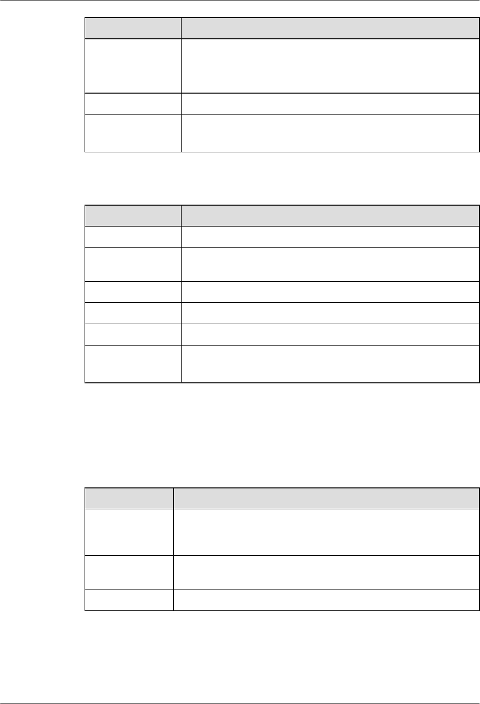
Attribute Description
Cable type E1 75-ohm unbalanced coaxial cable
E1 120-ohm balanced twisted pair cable
E1 trunk cable extension
Working mode Unchannelized E1
Function Backup
Terminal access
Table 5-31 Attributes of unchannelized T1 interfaces
Attribute Description
Connector type DB9
Standards
compliance
G.703 or G.704
Transmission rate 1.544 Mbit/s
Cable type T1 100-ohm coaxial cable
Working mode Unchannelized T1
Function Backup
Terminal access
Technical Specifications
Table 5-32 describes the technical specifications of the 1E1T1-F/2E1T1-F.
Table 5-32 Technical specifications of the 1E1T1-F/2E1T1-F
Item Specification
Dimensions
(depth x width x
height)
223.5 mm x 100.1 mm x 19.82 mm (8.8 in. x 3.94 in. x 0.78 in.)
Maximum power
consumption
7 W
Weight 0.3 kg (0.66 lb)
Huawei AR1200-S&2200-S Series Enterprise Routers
Hardware Description 5 Cards
Issue 03 (2012-04-20) Huawei Proprietary and Confidential
Copyright © Huawei Technologies Co., Ltd.
49
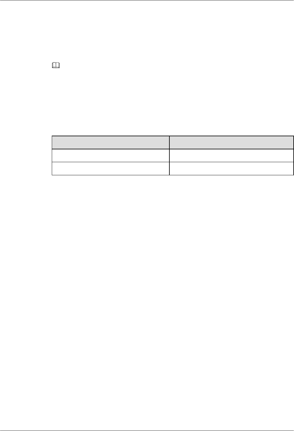
5.4.5 1SA/2SA-1/2-Port-Synchronous/Asynchronous WAN
Interface Card
The 1SA/2SA is the 1-port/2-port synchronous/asynchronous serial interface module on the AR
routers.
NOTE
l1/2: indicates one interface or two interfaces.
lS: indicates synchronous serial interface.
lA: indicates asynchronous serial interface.
Table 5-33 lists the number of interfaces on the 1SA and 2SA.
Table 5-33 Number of interfaces on the 1SA and 2SA
Card Name Quantity of Interfaces
1SA 1
2SA 2
Functions and Applications
Functions
The 1SA/2SA provides the following functions:
lA synchronous serial interface can function as a DCE or DTE. It supports multiple physical
layer protocols, such as V.24, V.35, and X.21, but does not support X.21 DCE. The
maximum rate of V.24 is 64 kbit/s and V.35 is 2.048 Mbit/s.
lAn asynchronous serial interface supports the RS232 protocol and provides a maximum
transmission rate of 115.2 kbit/s.
lThe 1SA/2SA provides system management channels by using in-band GE channels and
implements in-service upgrade by using system management channels.
lThe system powers on or off the 1SA/2SA and monitors the current of the 1SA/2SA; the
backplane provides 12 V voltage for the 1SA/2SA.
lThe 1SA/2SA is hot swappable.
Applications
1SA/2SA can be installed into the SIC slot of the AR1200-S, and AR2220-S.
Panel and Interfaces
Figure 5-12 shows the appearance of the 1SA.
Huawei AR1200-S&2200-S Series Enterprise Routers
Hardware Description 5 Cards
Issue 03 (2012-04-20) Huawei Proprietary and Confidential
Copyright © Huawei Technologies Co., Ltd.
50
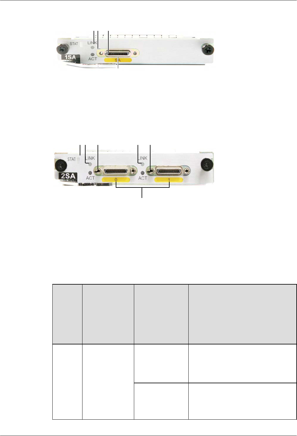
Figure 5-12 Appearance of the 1SA
a
1 2 3
Figure 5-13 shows the appearance of the 2SA.
Figure 5-13 Appearance of the 2SA
a
12 3 2 3
Buttons and Indicators on the Panel
Table 5-34 describes the buttons and indicators on the 1SA/2SA panel.
Table 5-34 Buttons and indicators on the 1SA/2SA panel
Numbe
r in
Figure
5-12
and
Figure
5-13
Indicator Color Description
1STAT Green If the indicator blinks once 2s (0.5 Hz),
the system is running properly.
If the indicator blinks once 0.25s (4 Hz),
the system is powering on or restarting.
Red If the indicator is red, a fault that affects
services occurs and cannot be rectified
automatically. The fault needs to be
rectified manually.
Huawei AR1200-S&2200-S Series Enterprise Routers
Hardware Description 5 Cards
Issue 03 (2012-04-20) Huawei Proprietary and Confidential
Copyright © Huawei Technologies Co., Ltd.
51
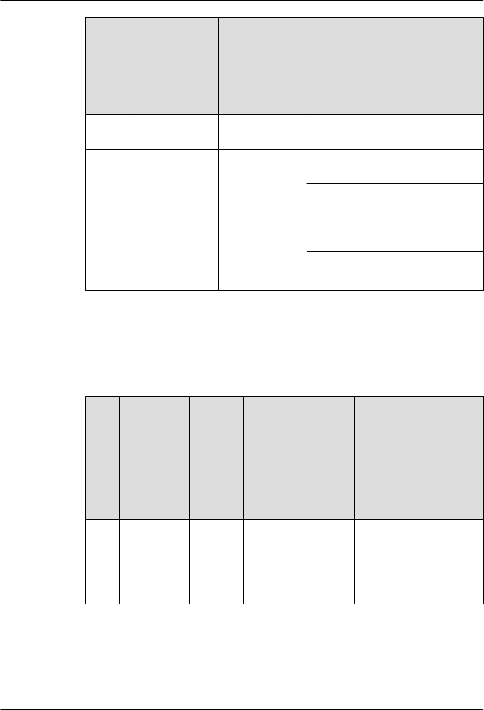
Numbe
r in
Figure
5-12
and
Figure
5-13
Indicator Color Description
Off If the indicator is off, the software is not
running or is being reset.
2 and 3 Synchronous/
Asynchronous
serial interface
indicators:
lThe LINK
indicator is in
green.
lThe ACT
indicator is in
yellow.
Green If the indicator is steady on, a link has
been established.
If the LINK indicator is off, the link is
not connected.
Yellow If the indicator is blinking, data is being
transmitted or received.
If the ACT indicator is off, no data is
transmitted or received.
Interfaces
Table 5-35 describes the types and functions of interfaces on the 1SA/2SA.
Table 5-35 Types and functions of interfaces on the 1SA/2SA
Lett
er in
Figu
re
5-12
and
Figu
re
5-13
Name Quantity Description Cable Type
a DB28 1SA: 1
2SA: 2
The synchronous/
asynchronous serial
interface cable is
selected according to
attributes of the
connected line.
6.8 Synchronous/
Asynchronous Serial
Interface Cables
Huawei AR1200-S&2200-S Series Enterprise Routers
Hardware Description 5 Cards
Issue 03 (2012-04-20) Huawei Proprietary and Confidential
Copyright © Huawei Technologies Co., Ltd.
52
Interface Attributes
Table 5-36 Attributes of synchronous/asynchronous serial interfaces
Attribute Description
Synchronous Serial Interface Asynchronous Serial
Interface
Connector
type
DB28
Standards
compliance
and working
mode
lV.24 DTE
lV.24 DCE
lV.35 DTE
lV.35 DCE
lX.21 DTE
lRS449 DTE
lRS449 DCE
lRS530 DTE
lRS530 DCE
RS232
Minimum
baud rate (bit/
s)
1200 1200 600
Maximum
baud rate (bit/
s)
64 k 2.048 M 115.2 k
Cable type lV.24 DTE cable
lV.24 DCE cable
lV.35 DTE cable
lV.35 DCE cable
lX.21 DTE cable
lRS449 DTE cable
lRS449 DCE cable
lRS530 DTE cable
lRS530 DCE cable
Function DDN leased line lModem dial-up
lBackup
Terminal access lAsynchronous leased line
lTerminal access
Technical Specifications
Table 5-37 describes the technical specifications of the 1SA/2SA.
Huawei AR1200-S&2200-S Series Enterprise Routers
Hardware Description 5 Cards
Issue 03 (2012-04-20) Huawei Proprietary and Confidential
Copyright © Huawei Technologies Co., Ltd.
53
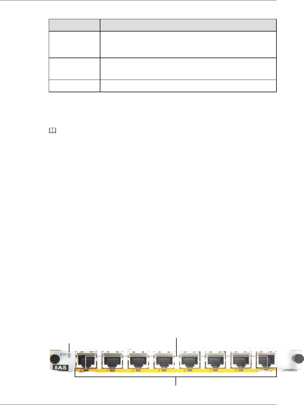
Table 5-37 Technical specifications of the 1SA/2SA
Item Specification
Dimensions
(Depth x Width x
Height)
223.5 mm x 100.1 mm x 19.82 mm (8.8 in. x 3.94 in. x 0.78 in.)
Maximum power
consumption
l1SA: 10 W
l2SA: 11.7 W
Weight 0.3 kg (0.66 lb)
5.4.6 8AS (8-Port-Asynchronous WAN Interface Card)
The 8AS is an 8-port asynchronous serial interface module on the AR routers.
NOTE
8AS stands for:
l8: eight interfaces
lAS: asynchronous serial interface
Functions and Applications
Functions
The 8AS sends, receives, and processes asynchronous data traffic.
lSupports a maximum of 115.2 kbit/s transmission rate for each asynchronous serial
interface.
lSupports terminal access and asynchronous leased lines.
lFunctions as a dialup access server for small and medium-sized ISPs when asynchronous
serial interfaces are used for dialup.
Applications
The 8AS is installed into the WSIC slot of the AR1200-S and AR2220-S. On the AR1200-S, a
WSIC slot consists of two SIC slots.
Panel and Interfaces
Figure 5-14 shows the appearance of the 8AS panel.
Figure 5-14 Appearance of the 8AS panel
a
12
Huawei AR1200-S&2200-S Series Enterprise Routers
Hardware Description 5 Cards
Issue 03 (2012-04-20) Huawei Proprietary and Confidential
Copyright © Huawei Technologies Co., Ltd.
54
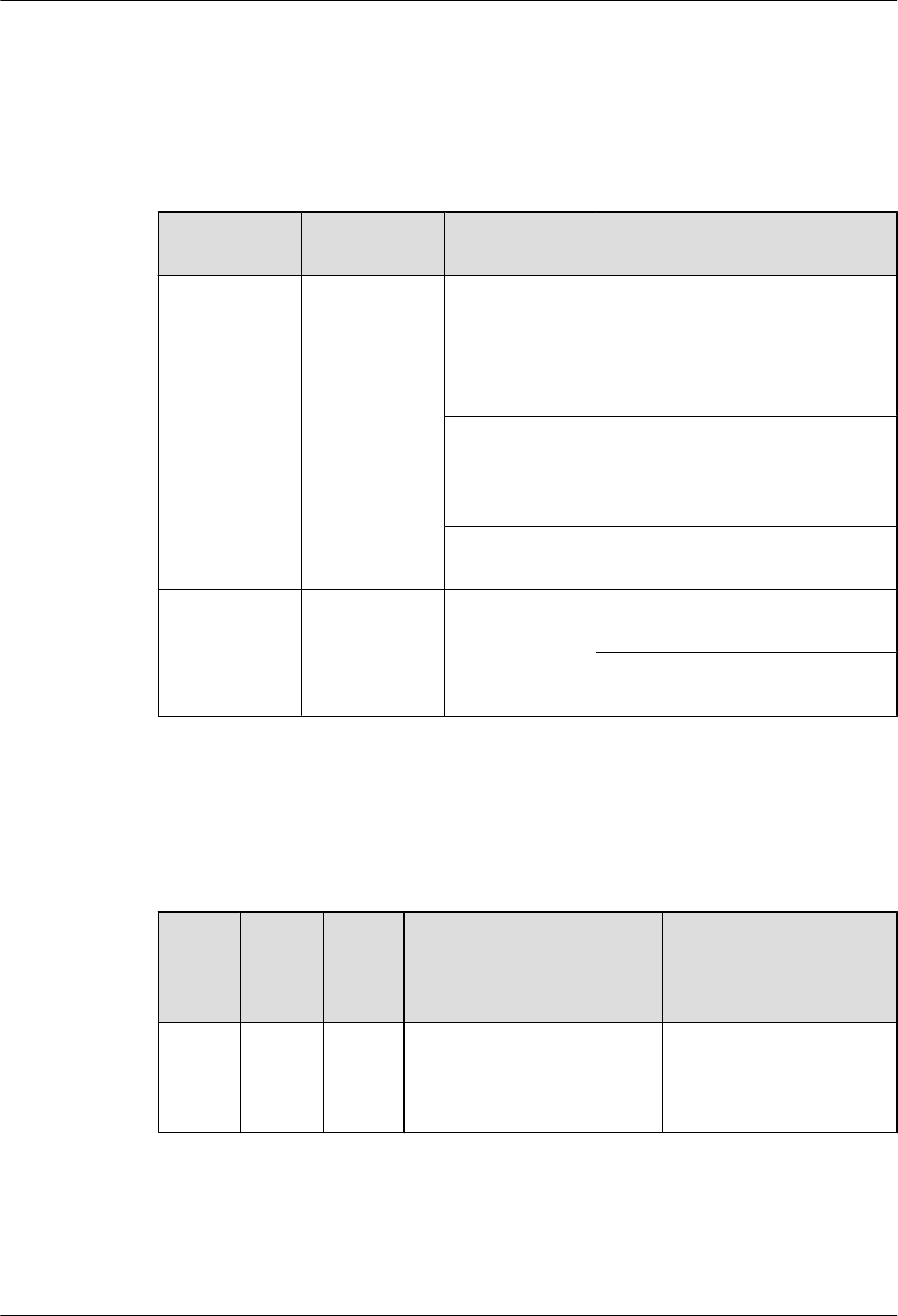
Buttons and Indicators on the Panel
Table 5-38 describes the buttons and indicators on the 8AS panel.
Table 5-38 Buttons and indicators on the 8AS panel
Number in
Figure 5-14
Indicator Color Description
1STAT Green If the indicator blinks once 2s (0.5
Hz), the system is running properly.
If the indicator blinks once 0.25s (4
Hz), the system is powering on or
restarting.
Red If the indicator is red, a fault that
affects services occurs and cannot be
rectified automatically. The fault
needs to be rectified manually.
Off If the indicator is off, the software is
not running or is being reset.
2 LINK
(interface status
indicator)
Green If the indicator is steady on, a link
has been established.
If the indicator is off, no link is
established.
Interfaces
Table 5-39 describes the types and functions of interfaces on the 8AS.
Table 5-39 Types and functions of interfaces on the 8AS
Letter
in
Figure
5-14
Name Quant
ity
Description Cable Type
a RJ45 8 Interfaces on the 8AS send,
receive, and process
asynchronous data traffic
using customized RJ45 cables.
6.12 8AS Cable
Huawei AR1200-S&2200-S Series Enterprise Routers
Hardware Description 5 Cards
Issue 03 (2012-04-20) Huawei Proprietary and Confidential
Copyright © Huawei Technologies Co., Ltd.
55
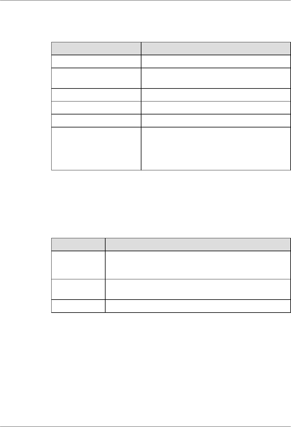
Interface Attributes
Table 5-40 Attributes of asynchronous serial interfaces
Attribute Description
Connector type RJ45
Standards compliance and
working mode
RS232
Minimum baud rate (bit/s) 300
Maximum baud rate (bit/s) 115.2 k
Cable type Customized RJ45 cable
Function lModem dial-up
lBackup
lAsynchronous leased line
lTerminal access
Technical Specifications
Table 5-41 describes the technical specifications of the 8AS.
Table 5-41 Technical specifications of the 8AS
Item Specification
Dimensions
(depth x width x
height)
223.5 mm x 201 mm x 19.82 mm (8.8 in. x 7.92 in. x 0.78 in.)
Maximum power
consumption
8.9 W
Weight 0.6 kg (1.32 lb)
5.4.7 1BST (1-Port-ISDN S/T WAN Interface Card)
The 1BST is the ISDN module on the AR routers and provides one ISDN S/T interface, which
transmits data services.
The 1BST transmits, receives, and processes 1-channel ISDN BRI S/T data flow.
Functions and Applications
Huawei AR1200-S&2200-S Series Enterprise Routers
Hardware Description 5 Cards
Issue 03 (2012-04-20) Huawei Proprietary and Confidential
Copyright © Huawei Technologies Co., Ltd.
56
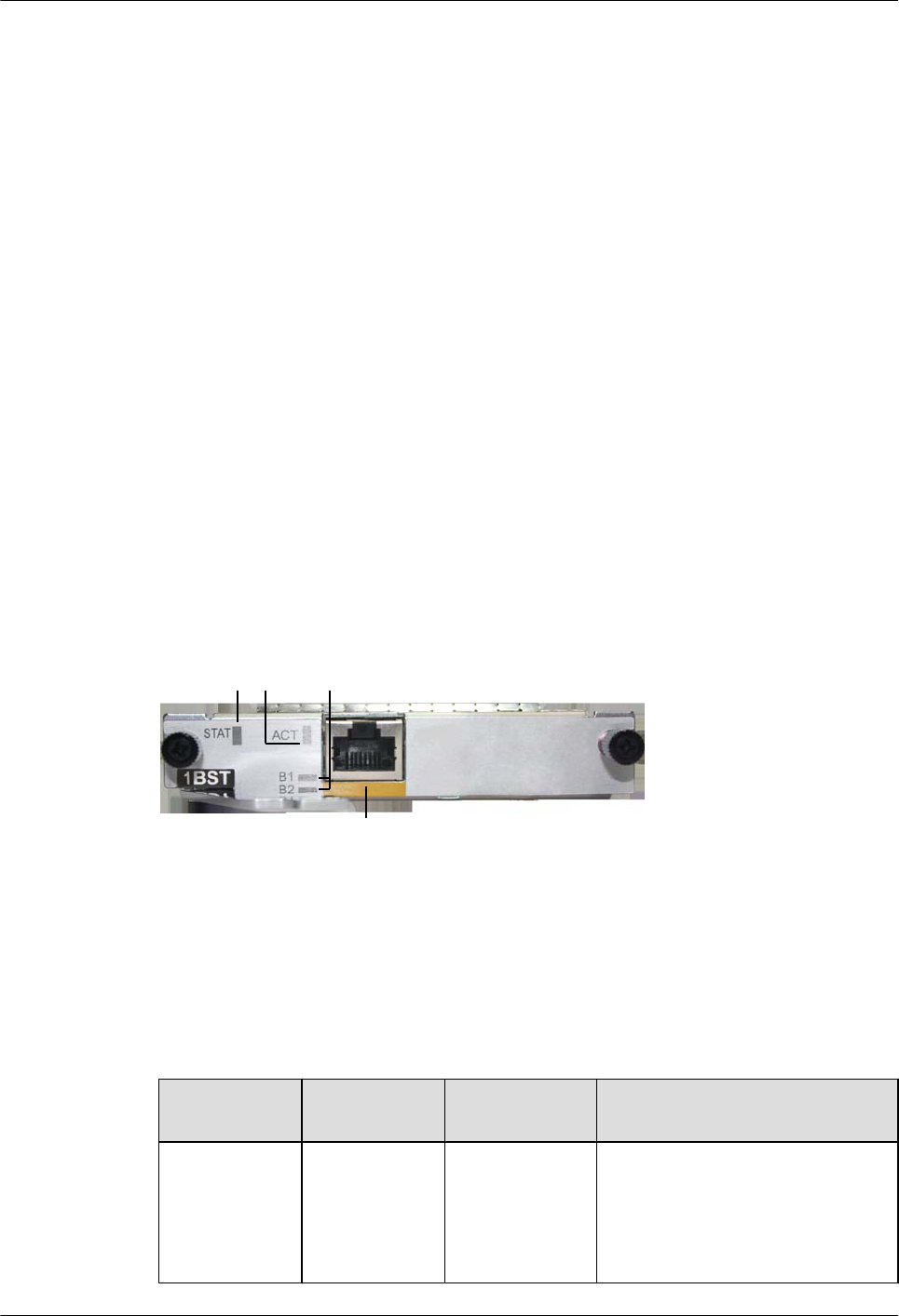
Functions
The 1BST provides one ISDN S/T interface for data access.
The 1BST consists of the following modules:
lCPU control module: manages the system and loads programs.
lCPLD logic module: provides the working clock and reset signals for the chip, controls the
service port status, and monitors the board clock.
lISDN chip module: provides S/T interface access, supports TE mode, and provides parallel
interfaces and serial interfaces.
lPower supply module: conducts power from backplane to card.
lClock module: provides the working clock for the CPU and working modules.
Applications
The 1BST is installed into the SIC slot of the AR1200-S and AR2220-S.
Panel and Interfaces
Figure 5-15 shows the appearance of the 1BST panel.
Figure 5-15 Appearance of the 1BST panel
a
2
13
Buttons and Indicators on the Panel
Table 5-42 describes the buttons and indicators on the 1BST panel.
Table 5-42 Buttons and indicators on the 1BST panel
Number in
Figure 5-15
Indicator Color Description
1STAT Green If the indicator blinks once 2s (0.5
Hz), the system is running properly.
If the indicator blinks once 0.25s (4
Hz), the system is powering on or
restarting.
Huawei AR1200-S&2200-S Series Enterprise Routers
Hardware Description 5 Cards
Issue 03 (2012-04-20) Huawei Proprietary and Confidential
Copyright © Huawei Technologies Co., Ltd.
57
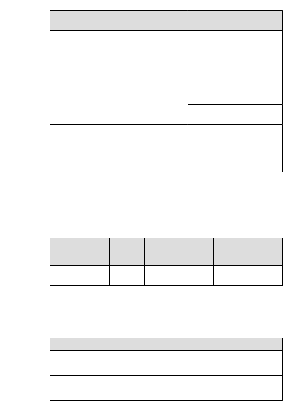
Number in
Figure 5-15
Indicator Color Description
Red If the indicator is red, a fault that
affects services occurs and cannot be
rectified automatically. The fault
needs to be rectified manually.
Off If the indicator is off, the software is
not running or is being reset.
2 ACT (interface
status
indicator)
Green If the indicator is steady on, the
ISDN channel is activated.
If the indicator is off, the ISDN
channel is deactivated.
3 B1/B2 Green If the indicator is blinking, the B1/
B2 channel of the ISDN channel is
being occupied.
If the indicator is off, the B1/B2
channel of the ISDN channel is idle.
Interfaces
Table 5-43 describes the types and functions of interfaces on the 1BST.
Table 5-43 Types and functions of interfaces on the 1BST
Letter in
Figure
5-15
Name Quantity Description Cable Type
a RJ45 1 ISDN S/T interfaces are
provided.
6.10 ISDN-ST Cables
Interface Attributes
Table 5-44 ISDN S/T interface attributes
Item Description
Connector RJ45
Standards compliance ITU-T I.430, Q.921, Q.931
Rate 192 kbit/s
Bandwidth 0 to 100 MHz
Huawei AR1200-S&2200-S Series Enterprise Routers
Hardware Description 5 Cards
Issue 03 (2012-04-20) Huawei Proprietary and Confidential
Copyright © Huawei Technologies Co., Ltd.
58
Item Description
Cable lTE: standard ISDN S/T interface cables (straight-
through cables)
lNT: ISDN S/T interface crossover cables
Technical Specifications
Table 5-45 describes the technical specifications of the 1BST.
Table 5-45 Technical specifications of the 1BST
Item Specification
Dimensions
(depth x width x
height)
223.5 mm x 100.1 mm x 19.82 mm (8.8 in. x 3.94 in. x 0.78 in.)
Maximum power
consumption
12 W
Weight 0.3 kg (0.66 lb)
5.4.8 1CPOS-155M (1-Port Channelized POS Interface Card)
1CPOS-155M provides an STM-1/OC3 optical interface to implement 63-channel E1 or 84-
channel T1 transmission in compliance with SDH/SONET.
NOTE
1CPOS-155M stands for:
l1: one interface
lC: channelized
lPOS: Packet Over SDH/SONET
l155M: a rate of 155.52 Mbit/s
Functions and Applications
Functions
1CPOS-155M has the following functions:
lSupports clear channel (unframed) E1, non-channelized (framed) E1, and channelized CE1.
lSupports non-channelized (framed) T1 and channelized CT1.
lSupports the link layer protocols such as HDLC and PPP and a maximum of 1024 HDLC
channels.
Huawei AR1200-S&2200-S Series Enterprise Routers
Hardware Description 5 Cards
Issue 03 (2012-04-20) Huawei Proprietary and Confidential
Copyright © Huawei Technologies Co., Ltd.
59
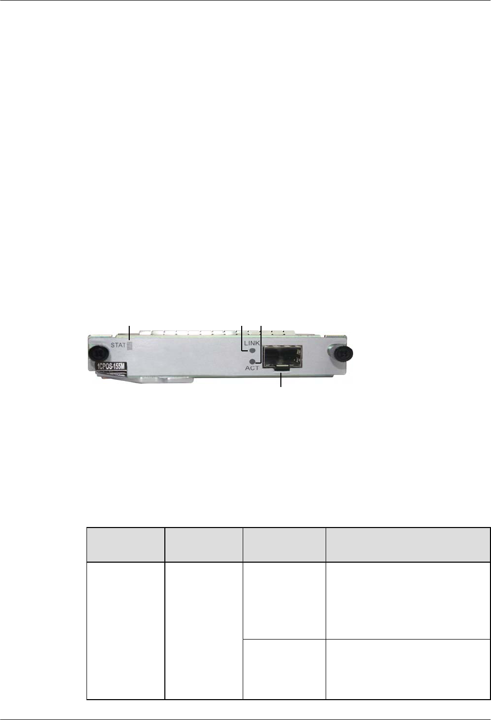
lSupports four SFP optical module types: short-distance multi-mode (1310 nm), mid-
distance single-mode (1310 nm), long-distance single-mode (1310 nm), and ultra-long-
distance single-mode (1550 nm).
lAutomatically starts and loads configurations after being powered on, provides the system
management function using a GE inband channel, and uses the UART serial interface as
the escape channel for subcard.
lUses the 12 V power provided by the backplane, be powered on and off by the main control
board, and monitors voltage and current.
lBe hot swappable.
Applications
1CPOS-155M can be installed in a SIC slot of AR2220-S.
Panel and Interfaces
Figure 5-16 shows the appearance of the 1CPOS-155M.
Figure 5-16 Appearance of the 1CPOS-155M
12 3
a
Buttons and Indicators on the Panel
Table 5-46 describes the buttons and indicators on the 1CPOS-155M panel.
Table 5-46 Buttons and indicators on the 1CPOS-155M panel
Number in
Figure 5-16
Indicator Color Description
1STAT Green If the indicator blinks once 2s (0.5
Hz), the system is running properly.
If the indicator blinks once 0.25s (4
Hz), the system is powering on or
restarting.
Red If the indicator is red, a fault that
affects services occurs and cannot be
rectified automatically. The fault
needs to be rectified manually.
Huawei AR1200-S&2200-S Series Enterprise Routers
Hardware Description 5 Cards
Issue 03 (2012-04-20) Huawei Proprietary and Confidential
Copyright © Huawei Technologies Co., Ltd.
60
Number in
Figure 5-16
Indicator Color Description
Off If the indicator is off, the software is
not running or is being reset.
2 LINK Green If the indicator is steady on, a link
has been established.
If the indicator is off, no link is
established.
3 ACT Yellow If the indicator is blinking, data is
being transmitted or received.
If the indicator is off, no data is being
transmitted or received.
Interfaces
Table 5-47 describes the types and functions of interfaces on the 1CPOS-155M.
Table 5-47 Types and functions of interfaces on the 1CPOS-155M
Letter in
Figure 5-16
Name Quantit
y
Description Cable Type
a SFP
optical
interface
1 The
1CPOS-155M
provides one
SFP optical
interface to
transmit and
receive SDH/
SONET frames.
6.6 Optical Fiber
Interface Attributes
Table 5-48 CPOS interface attributes
Attribute Description
Connector type LC/PC
Optical interface
attribute
Depending on the SFP optical module
Standards
compliance
STM-1
Frame format SDH/SONET
Huawei AR1200-S&2200-S Series Enterprise Routers
Hardware Description 5 Cards
Issue 03 (2012-04-20) Huawei Proprietary and Confidential
Copyright © Huawei Technologies Co., Ltd.
61
Attribute Description
Network layer
protocol
IP
Table 5-49 Attributes of the SFP optical module supported by the CPOS interface
Attribute Description
Transmissio
n distance
2 km 15 km 40 km 80 km
Center
wavelength
1310 nm 1310 nm 1310 nm 1550 nm
Transmittin
g power
-19.0 dBm to
-14.0 dBm
-15.0 dBm to 8.0
dBm
-15.0 dBm to 8.0
dBm
-3.0 dBm to 0
dBm
Receiver
sensitivity
-28.0 dBm -23.0 dBm -23.0 dBm -32.98 dBm
Overload
optical
power
-14.0 dBm -10.17 dBm -8.0 dBm -8.0 dBm
Extinction
ratio
>10.0 dB 58.86 dB 14.08 dB 43.09 dB
Fiber type Multimode Single-mode
Technical Specifications
Table 5-50 describes the technical specifications of the 1CPOS-155M.
Table 5-50 Technical specifications of the 1CPOS-155M
Item Specification
Dimensions
(depth x width x
height)
223.5 mm x 100.1 mm x 19.82 mm (8.8 in. x 3.94 in. x 0.78 in.)
Maximum power
consumption
12 W
Weight 0.3 kg (0.66 lb)
5.4.9 3G-HSPA+7 (3G WAN Interface Card)
A 3G-HSPA+7 interface card provides two 3G antenna interfaces and one mini USB interface.
Huawei AR1200-S&2200-S Series Enterprise Routers
Hardware Description 5 Cards
Issue 03 (2012-04-20) Huawei Proprietary and Confidential
Copyright © Huawei Technologies Co., Ltd.
62
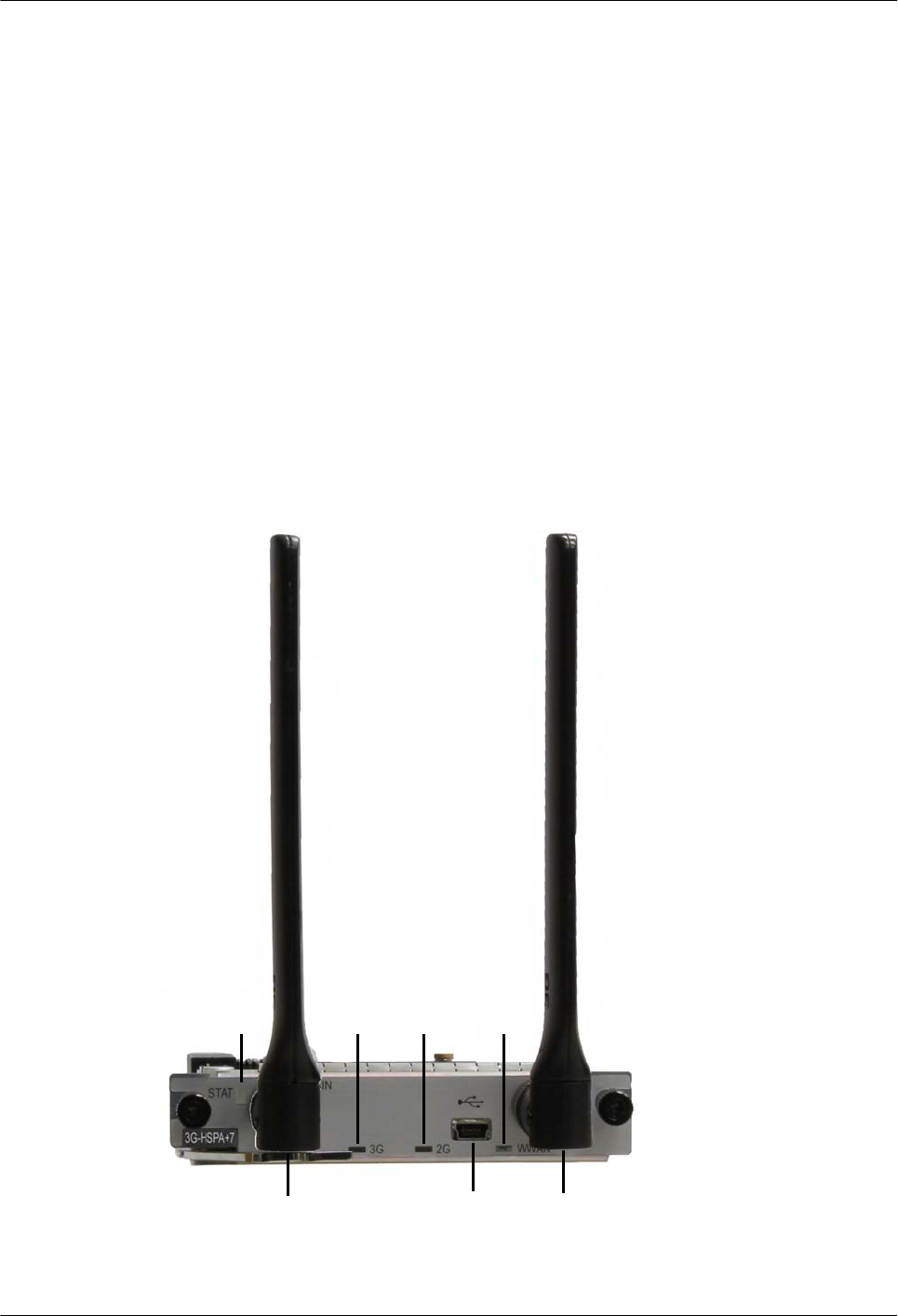
Functions and Applications
Functions
The 3G-HSPA+7 interface card provides WAN access through WCDMA.
Applications
The 3G-HSPA+7 interface card can be installed in the SIC slot on the AR1200-S and AR2220-
S chassis.
Panel and Interfaces
Figure 5-17 shows the appearance of the 3G-HSPA+7 interface card.
Figure 5-17 3G-HSPA+7 panel
a
12 3 4
a
b
Huawei AR1200-S&2200-S Series Enterprise Routers
Hardware Description 5 Cards
Issue 03 (2012-04-20) Huawei Proprietary and Confidential
Copyright © Huawei Technologies Co., Ltd.
63

Buttons and Indicators on the Panel
Table 5-51 describes the buttons and indicators on the 3G-HSPA+7 panel.
Table 5-51 Buttons and indicators on the 3G-HSPA+7 panel
Number
in
Figure
5-17
Indicator Color Description
1STAT Green If the indicator is steady on, the router
has been powered on, but the system
software is not running.
If the indicator blinks once every 2s (0.5
Hz), the system is running properly.
If the indicator blinks once every 0.25s
(4 Hz), the system is loading software
after power-on or is restarting.
Red If the indicator is steady on, a fault that
affects services has occurred and
cannot be rectified automatically. The
fault needs to be rectified manually.
Orange If the indicator is off, the software is not
running or is being reset.
2 3G Green If the indicator is steady on, the 3G
signal strength is high.
If the indicator blinks once every 2s (0.5
Hz), the 3G signals strength is low.
If the indicator blinks once every 0.25s
(4 Hz), the 3G signals strength is
medium.
32G Green If the indicator is steady on, the 2G
signal strength is high.
If the indicator blinks once every 2s (0.5
Hz), the 2G signals strength is low.
If the indicator blinks once every 0.25s
(4 Hz), the 2G signals strength is
medium.
Huawei AR1200-S&2200-S Series Enterprise Routers
Hardware Description 5 Cards
Issue 03 (2012-04-20) Huawei Proprietary and Confidential
Copyright © Huawei Technologies Co., Ltd.
64
Number
in
Figure
5-17
Indicator Color Description
4WWAN Green If the indicator is steady on, the 3G/2G
connection is being established or is
active.
If the indicator is blinking, data is being
transmitted or received over the 3G/2G
connection.
If the indicator is off, the 3G/2G
connection has not been established or
is inactive.
Interfaces
Table 5-52 describes the types and functions of interfaces on the 3G-HSPA+7 interface card.
Table 5-52 Types and functions of interfaces on the 3G-HSPA+7 interface card
Lette
r in
Figu
re
5-17
Name Qu
ant
ity
Description Cable Type
a Antenna
interface
2 The 3G-HSPA+7 interface card provides two
3G interfaces to transmit and receive 3G
service data. One interface is the primary
interface, and the other is the secondary
interface.
3G antenna
bMini
USB
interface
1 The mini USB interface is used to
commission the 3G module.
Mini USB cable
Interface Attributes
Table 5-53 3G interface attributes
Item Description
Connector SMA RF: connects to an antenna to provide wireless access.
mini USB: connects to a USB flash drive with third-party wireless
network test software, for example, Qualcomm CAIT.
Huawei AR1200-S&2200-S Series Enterprise Routers
Hardware Description 5 Cards
Issue 03 (2012-04-20) Huawei Proprietary and Confidential
Copyright © Huawei Technologies Co., Ltd.
65
Item Description
Standards
compliance and
frequency bands
supported
GSM/GPRS/EDGE: 850/900/1800/1900 (MHz)
HSPA+/HSUPA/HSDPA/WCDMA: 2100/1900/900/850 (MHz)
Rate GSM CS:
lUpstream (Tx): 9.6kbit/s
lDownstream (Rx): 9.6kbit/s
GPRS/EDGE: Multi-slot Class 12, Class B
WCDMA CS:
lUpstream (Tx): 64 kbit/s
lDownstream (Rx): 64 kbit/s
WCDMA PS:
lUpstream (Tx): 384 kbit/s
lDownstream (Rx): 384 kbit/s
HSPA:
lUpstream (Tx): 5.76 Mbit/s
lDownstream (Rx): 14.4 Mbit/s
HSPA+:
lUpstream (Tx): 5.76 Mbit/s
lDownstream (Rx): 21 Mbit/s
Network protocol WCDMA/HSPA/GPRS/EDGE
Installing a 3G SIM Card
For details on how to installing a 3G SIM card on the 3G-HSPA+7 interface card, see the
AR1200&2200&3200 Quick Installation Guide.
Technical Specifications
Table 5-54 describes the technical specifications of the 3G-HSPA+7 interface card.
Table 5-54 Technical specifications of the 3G-HSPA+7
Parameter Description
Dimensions (W x
D x H)
100.1 mm x 223.5 mm x 19.82 mm
Maximum power
consumption
7 W
Weight 0.2 kg
Huawei AR1200-S&2200-S Series Enterprise Routers
Hardware Description 5 Cards
Issue 03 (2012-04-20) Huawei Proprietary and Confidential
Copyright © Huawei Technologies Co., Ltd.
66
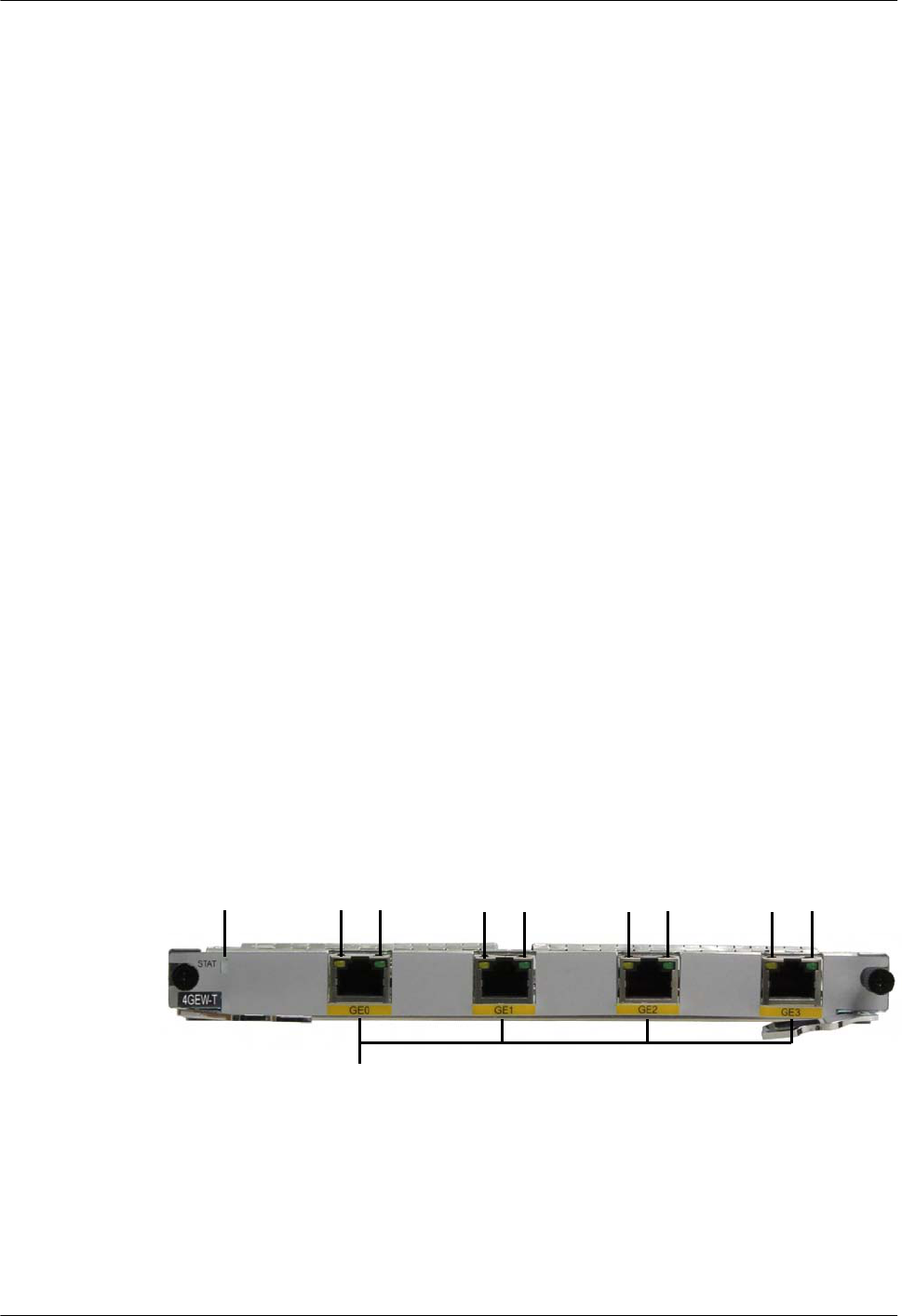
5.4.10 4GEW-T (4-Port-GE Electrical WAN Interface Card)
The 4GEW-T interface card provides four GE electrical interfaces.
4GEW-T stands for:
l4: four interfaces
lGE: 1000M Ethernet
lW: WAN
lT: electrical interface
Functions and Applications
Functions
The 4GEW-T interface card provides four GE electrical interfaces to implement data access and
line-speed switching.
The 4GEW-T interface card sends, receives, and processes GE data traffic. The four GE electrical
interfaces work in 10/100/1000 Mbit/s auto-negotiation mode.
Applications
The 4GEW-T interface card can be installed in the WSIC slot on the AR1200-S and AR2220-
S chassis.
Panel and Interfaces
Figure 5-18 shows the appearance of the 4GEW-T interface card.
Figure 5-18 4GEW-T panel
12323 2 323
a
Buttons and Indicators on the Panel
Table 5-55 describes the buttons and indicators on the 4GEW-T panel.
Huawei AR1200-S&2200-S Series Enterprise Routers
Hardware Description 5 Cards
Issue 03 (2012-04-20) Huawei Proprietary and Confidential
Copyright © Huawei Technologies Co., Ltd.
67
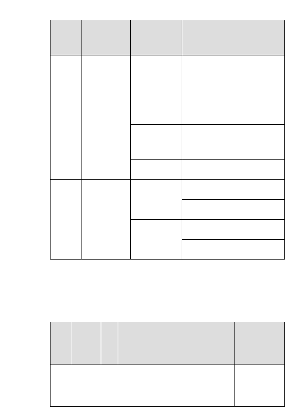
Table 5-55 Buttons and indicators on the 4GEW-T panel
Number
in
Figure
5-18
Indicator Color Description
1STAT Green If the indicator is steady on, the router
has been powered on, but the system
software is not running.
If the indicator blinks once every 2s (0.5
Hz), the system is running properly.
If the indicator blinks once every 0.25s
(4 Hz), the system is loading software
after power-on or is restarting.
Red If the indicator is steady on, a fault that
affects services has occurred and
cannot be rectified automatically. The
fault needs to be rectified manually.
Off If the indicator is off, the software is not
running or is being reset.
2 and 3 GE interface
indicators:
lThe LINK
indicator is in
green.
lThe ACT
indicator is in
yellow.
Green If the indicator is steady on, a link has
been established.
If the indicator is off, no link is
established.
Yellow If the indicator is blinking, the interface
is transmitting or receiving data.
If the indicator is off, no data is being
transmitted or received.
Interfaces
Table 5-56 describes the types and functions of interfaces on the 4GEW-T interface card.
Table 5-56 Types and functions of interfaces on the 4GEW-T interface card
Lette
r in
Figur
e
5-18
Name Qu
ant
ity
Description Cable Type
a 1000BA
SE-T
electrica
l
interface
4 The 4GEW-T interface card provides four
1000M electrical interfaces to transmit and
receive GE data traffic.
6.5 Network
Cable
Huawei AR1200-S&2200-S Series Enterprise Routers
Hardware Description 5 Cards
Issue 03 (2012-04-20) Huawei Proprietary and Confidential
Copyright © Huawei Technologies Co., Ltd.
68
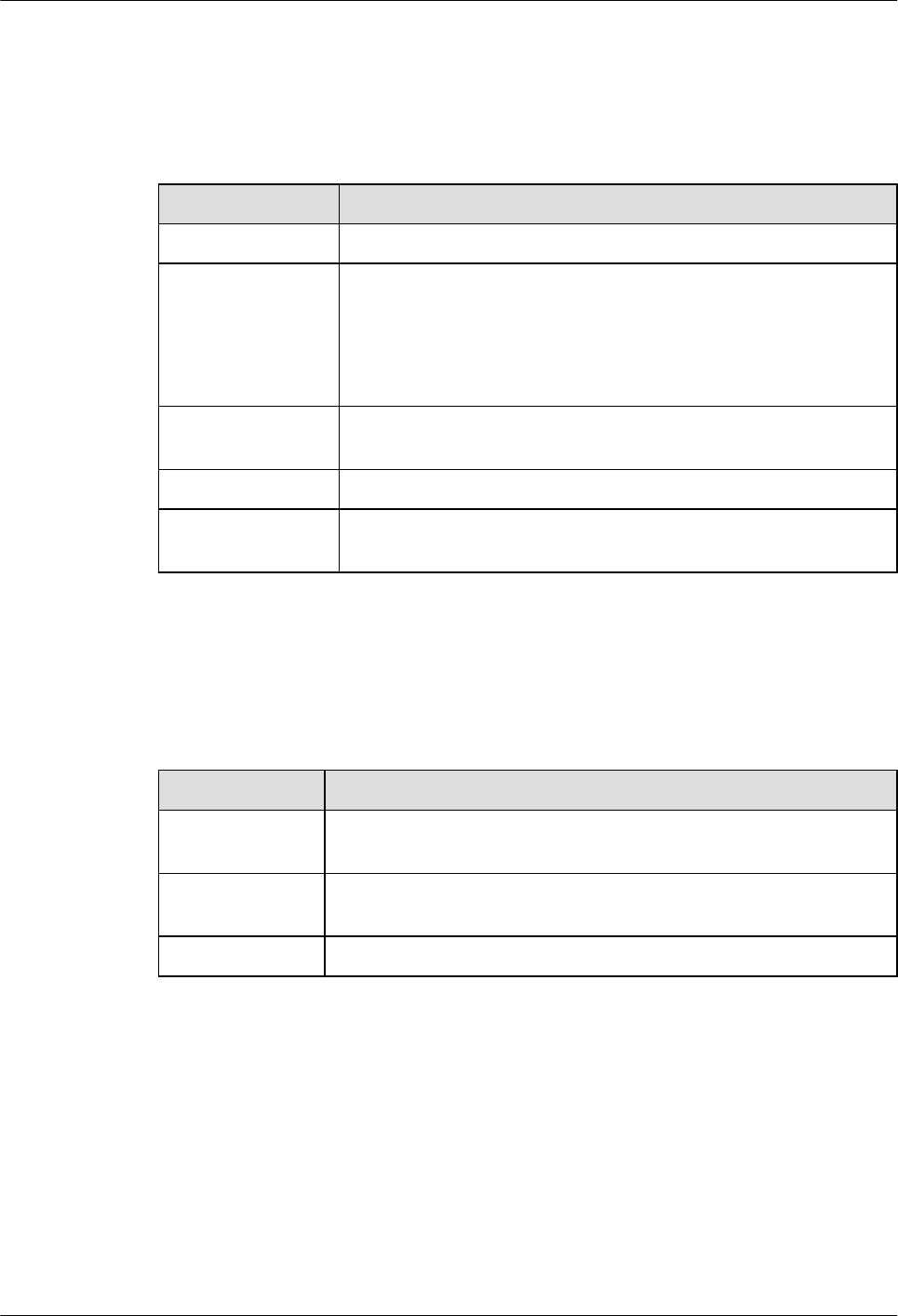
Interface Attributes
Table 5-57 Attributes of 1000BASE-T electrical interfaces
Item Description
Connector type RJ45
Interface attribute MDI/MDIX
NOTE
lThe interfaces of most network cards are medium dependent interfaces
(MDIs).
lMDIX interfaces are usually used on hubs or LAN switches.
Standards
compliance
IEEE802.3, IEEE802.3u, IEEE802.3ab
Frame format Ethernet_II, Ethernet_SAP, or Ethernet_SNAP
Network layer
protocol
IP
Technical Specifications
Table 5-58 describes the technical specifications of the 4GEW-T interface card.
Table 5-58 Technical specifications of the 4GEW-T
Parameter Description
Dimensions (W x
D x H)
201 mm x 223.5 mm x 19.82 mm
Maximum power
consumption
11 W
Weight 0.3 kg
5.4.11 4GEW-S (4-Port-GE Optical WAN Interface Card
The 4GEW-S interface card provides four GE optical interfaces.
4GEW-S stands for:
l4: four interfaces
lGE: 1000M Ethernet
lW: WAN
lS: optical interface
Huawei AR1200-S&2200-S Series Enterprise Routers
Hardware Description 5 Cards
Issue 03 (2012-04-20) Huawei Proprietary and Confidential
Copyright © Huawei Technologies Co., Ltd.
69
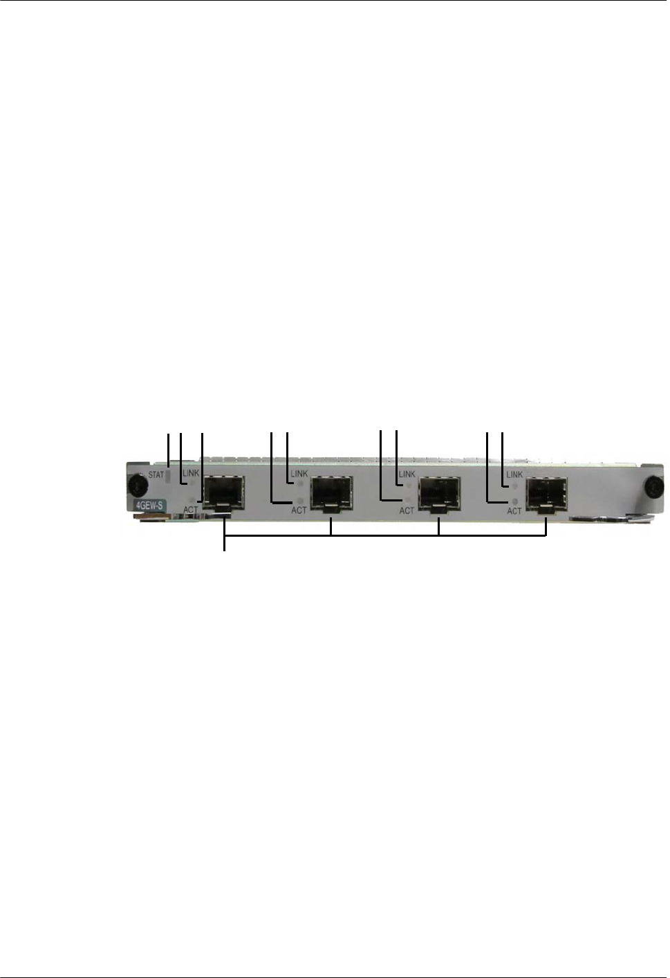
Functions and Applications
Functions
The 4GEW-S interface card provides four GE optical interfaces to implement data access and
line-speed switching.
The 4GEW-S interface card sends, receives, and processes GE data traffic. The four GE optical
interfaces work in 100/1000 Mbit/s auto-sensing mode.
Applications
The 4GEW-S interface card can be installed in the WSIC slot on the AR1200-S and AR2220-
S chassis.
Panel and Interfaces
Figure 5-19 shows the appearance of the 4GEW-S interface card.
Figure 5-19 4GEW-S panel
1
a
2 3 2 3 2323
Buttons and Indicators on the Panel
Table 5-59 describes the buttons and indicators on the 4GEW-S panel.
Huawei AR1200-S&2200-S Series Enterprise Routers
Hardware Description 5 Cards
Issue 03 (2012-04-20) Huawei Proprietary and Confidential
Copyright © Huawei Technologies Co., Ltd.
70
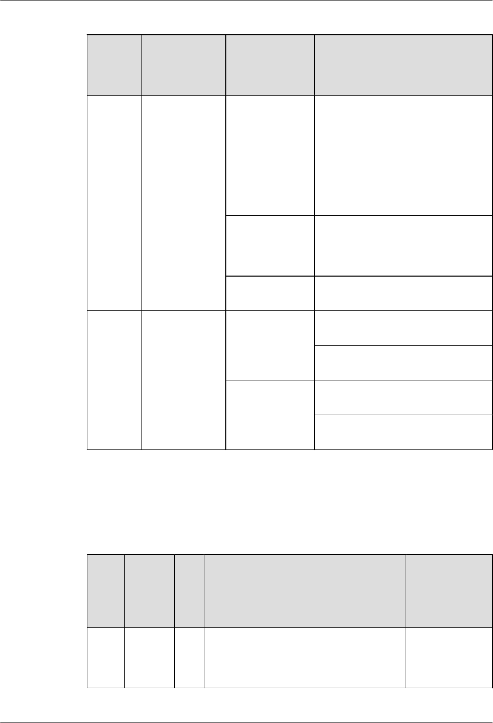
Table 5-59 Buttons and indicators on the 4GEW-S panel
Number
in
Figure
5-19
Indicator Color Description
1STAT Green If the indicator is steady on, the router
has been powered on, but the system
software is not running.
If the indicator blinks once every 2s (0.5
Hz), the system is running properly.
If the indicator blinks once every 0.25s
(4 Hz), the system is loading software
after power-on or is restarting.
Red If the indicator is steady on, a fault that
affects services has occurred and
cannot be rectified automatically. The
fault needs to be rectified manually.
Off If the indicator is off, the software is not
running or is being reset.
2 and 3 GE interface
indicators:
lThe LINK
indicator is in
green.
lThe ACT
indicator is in
yellow.
Green If the indicator is steady on, a link has
been established.
If the indicator is off, no link is
established.
Yellow If the indicator is blinking, the interface
is transmitting or receiving data.
If the indicator is off, no data is being
transmitted or received.
Interfaces
Table 5-60 describes the types and functions of interfaces on the 4GEW-S interface card.
Table 5-60 Types and functions of interfaces on the 4GEW-S interface card
Lette
r in
Figur
e
5-19
Name Qu
ant
ity
Description Cable Type
a 1000BA
SE-X
optical
interface
4 The 4GEW-S interface card provides four GE
optical interfaces to transmit and receive GE
service traffic.
6.6 Optical
Fiber
Huawei AR1200-S&2200-S Series Enterprise Routers
Hardware Description 5 Cards
Issue 03 (2012-04-20) Huawei Proprietary and Confidential
Copyright © Huawei Technologies Co., Ltd.
71
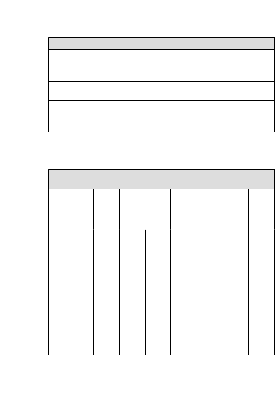
Interface Attributes
Table 5-61 Attributes of the 100/1000BASE-X GE optical interface
Attribute Description
Connector type LC/PC
Optical interface
attribute
Depending on the SFP optical module.
Standards
compliance
IEEE 802.3ab
Frame format Ethernet_II, Ethernet_SAP, or Ethernet_SNAP
Network layer
protocol
IP
Table 5-62 Attributes of the SFP optical module (100/1000 Mbit/s) supported by the GE optical
interface
Attri
bute
Description
Tran
smiss
ion
dista
nce
500 m 10 km 10 km (single-
mode bidirectional
fiber)
40 km 40 km 80 km 100 km
Cent
er
wave
lengt
h
850 nm 1310
nm
Tx:
1310
nm
Rx:
1490
nm
Tx:
1490
nm
Rx:
1310
nm
1310
nm
1550
nm
1550
nm
1550
nm
Tran
smitt
ing
powe
r
-9.5
dBm to
-2.5
dBm
-9.0
dBm to
-3.0
dBm
-9.0
dBm to
-3.0
dBm
-9.0
dBm to
-3.0
dBm
-5.0
dBm to
0 dBm
-5.0
dBm to
0 dBm
-2.0
dBm to
5.0
dBm
0 dBm
to 5
dBm
Rece
iver
sensi
tivity
-17.0
dBm
-20.0
dBm
-19.5
dBm
-19.5
dBm
-23
dBm
-22
dBm
-23.0
dBm
-30.0
dBm
Huawei AR1200-S&2200-S Series Enterprise Routers
Hardware Description 5 Cards
Issue 03 (2012-04-20) Huawei Proprietary and Confidential
Copyright © Huawei Technologies Co., Ltd.
72
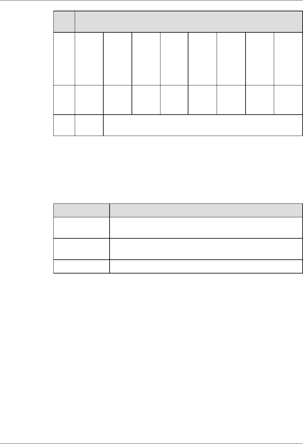
Attri
bute
Description
Over
load
optic
al
powe
r
0 dBm -3.0
dBm
-3.0
dBm
-3.0
dBm
-3.0
dBm
-3.0
dBm
-3.0
dBm
-9.0
dBm
Extin
ction
ratio
9 dB 9 dB 6 dB 6 dB 9 dB 8.5 dB 9 dB 8 dB
Fiber
type
Multi-
mode
Single-mode
Technical Specifications
Table 5-63 describes the technical specifications of the 4GEW-S interface card.
Table 5-63 Technical specifications of the 4GEW-S
Parameter Description
Dimensions (W x
D x H)
201 mm x 223.5 mm x 19.82 mm
Maximum power
consumption
8 W
Weight 0.3 kg
5.5 Voice Interface Card
This section describes the types, functions, applications, appearance, interfaces, and technical
specifications of the voice interface card.
5.5.1 2BST (2-Port-ISDN S/T Voice Interface Card)
The 2BST is the ISDN module on the AR routers and provides two ISDN S/T interfaces, which
transmit voice service.
The 2BST implements the ISDN BRI function and provides the bandwidth of two B channels
and one D channel:
lB channel: provides 64 kbit/s bandwidth and transmits voice service.
lD channel: is a signaling channel and provides 16 kbit/s bandwidth.
lThe total bandwidth of two B channels and one D channel is 144 kbit/s.
Huawei AR1200-S&2200-S Series Enterprise Routers
Hardware Description 5 Cards
Issue 03 (2012-04-20) Huawei Proprietary and Confidential
Copyright © Huawei Technologies Co., Ltd.
73
The S/T interface on the 2BST provides a rate of 192 kbit/s, including 144 kbit/s for data
transmission and 48 kbit/s for maintenance information transmission.
Table 5-64 lists the number of interfaces on the 1BST and 2BST.
Table 5-64 Number of interfaces on the 1BST and 2BST
Card
Name
User
Interface
Usage
Scenario
Mode Feed Supported
1BST One S/T
interface
Data services TE No
2BST Two S/T
interfaces
Voice services NT -40 V feed
NOTE
lTE: terminal equipment
lNT: network termination
2BST cards have two types: SIC and WSIC. Table 5-65 lists the slots where the SIC card and
WSIC card are installed.
Table 5-65 Slots of 2BST SIC and WSIC cards
Card Slot
2BST (SIC) SIC slot
2BST (WSIC) WSIC slot or XSIC slot
NOTE
In an XSIC slot, the WSIC card is installed in the lower part
of the slot. The WSIC card uses the XSIC slot ID as its own
slot ID.
Functions and Applications
Functions
The 2BST has the following functions:
lProvides two ISDN S/T interfaces for voice access.
lImplements NT mode.
The 2BST consists of the following modules:
lCPU control module: manages the system and loads programs.
lCPLD logic module: provides the working clock and reset signals for the chip, controls the
line -40 V feed, controls the service port status, and monitors the board clock.
Huawei AR1200-S&2200-S Series Enterprise Routers
Hardware Description 5 Cards
Issue 03 (2012-04-20) Huawei Proprietary and Confidential
Copyright © Huawei Technologies Co., Ltd.
74
lISDN chip module: provides S/T interface access, supports NT mode, and provides parallel
interfaces and serial interfaces.
lPower supply module: conducts power from backplane to card.
lClock module: provides the working clock for the CPU and working modules.
Applications
2BST (SIC) is installed into the SIC slot of the AR2220-S.
The 2BST (WSIC) is installed in a WSIC slot on the AR2220-S.
Panel and Interfaces
Figure 5-20 shows the appearance of the 2BST (SIC) panel.
Figure 5-20 Appearance of the 2BST (SIC) panel
a
1 2 3 2 3
Figure 5-21 shows the appearance of the 2BST (WSIC).
Figure 5-21 Appearance of the 2BST (WSIC) panel
a
12323
Buttons and Indicators on the Panel
Table 5-66 describes the buttons and indicators on the 2BST panel.
Huawei AR1200-S&2200-S Series Enterprise Routers
Hardware Description 5 Cards
Issue 03 (2012-04-20) Huawei Proprietary and Confidential
Copyright © Huawei Technologies Co., Ltd.
75
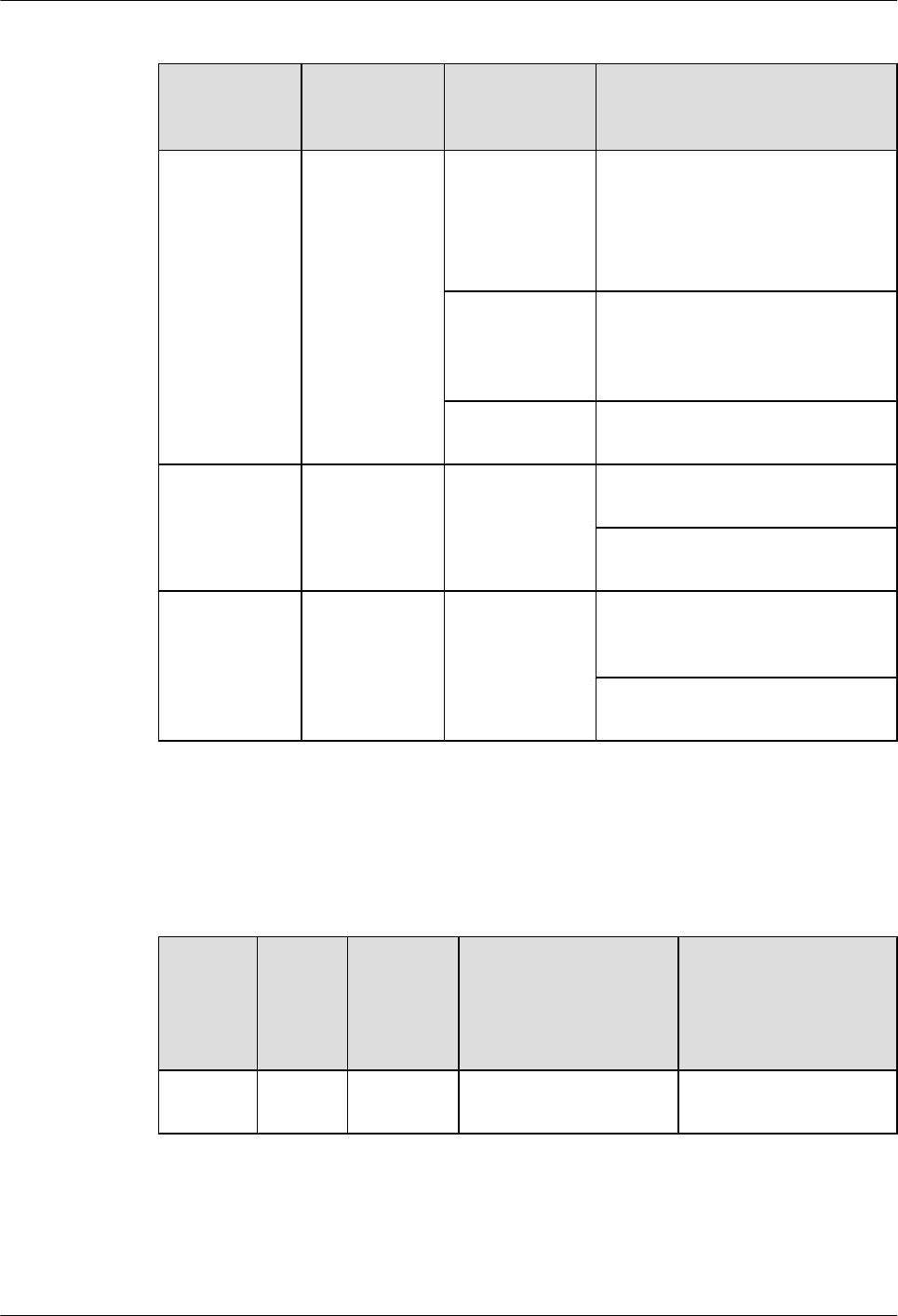
Table 5-66 Buttons and indicators on the 2BST panel
Number in
Figure 5-20,
Figure 5-21
Indicator Color Description
1STAT Green If the indicator blinks once 2s (0.5
Hz), the system is running properly.
If the indicator blinks once 0.25s (4
Hz), the system is powering on or
restarting.
Red If the indicator is red, a fault that
affects services occurs and cannot be
rectified automatically. The fault
needs to be rectified manually.
Off If the indicator is off, the software is
not running or is being reset.
2 ACT (interface
status
indicator)
Green If the indicator is steady on, the
ISDN channel is activated.
If the indicator is off, the ISDN
channel is deactivated.
3 B1/B2 Green If the indicator is blinking, the B1/
B2 channel of the ISDN channel is
being occupied.
If the indicator is off, the B1/B2
channel of the ISDN channel is idle.
Interfaces
Table 5-67 describes the types and functions of interfaces on the 2BST.
Table 5-67 Types and functions of interfaces on the 2BST
Letter in
Figure
5-20,
Figure
5-21
Name Quantity Description Cable Type
a RJ45 2 ISDN S/T interfaces are
provided.
6.10 ISDN-ST Cables
Huawei AR1200-S&2200-S Series Enterprise Routers
Hardware Description 5 Cards
Issue 03 (2012-04-20) Huawei Proprietary and Confidential
Copyright © Huawei Technologies Co., Ltd.
76
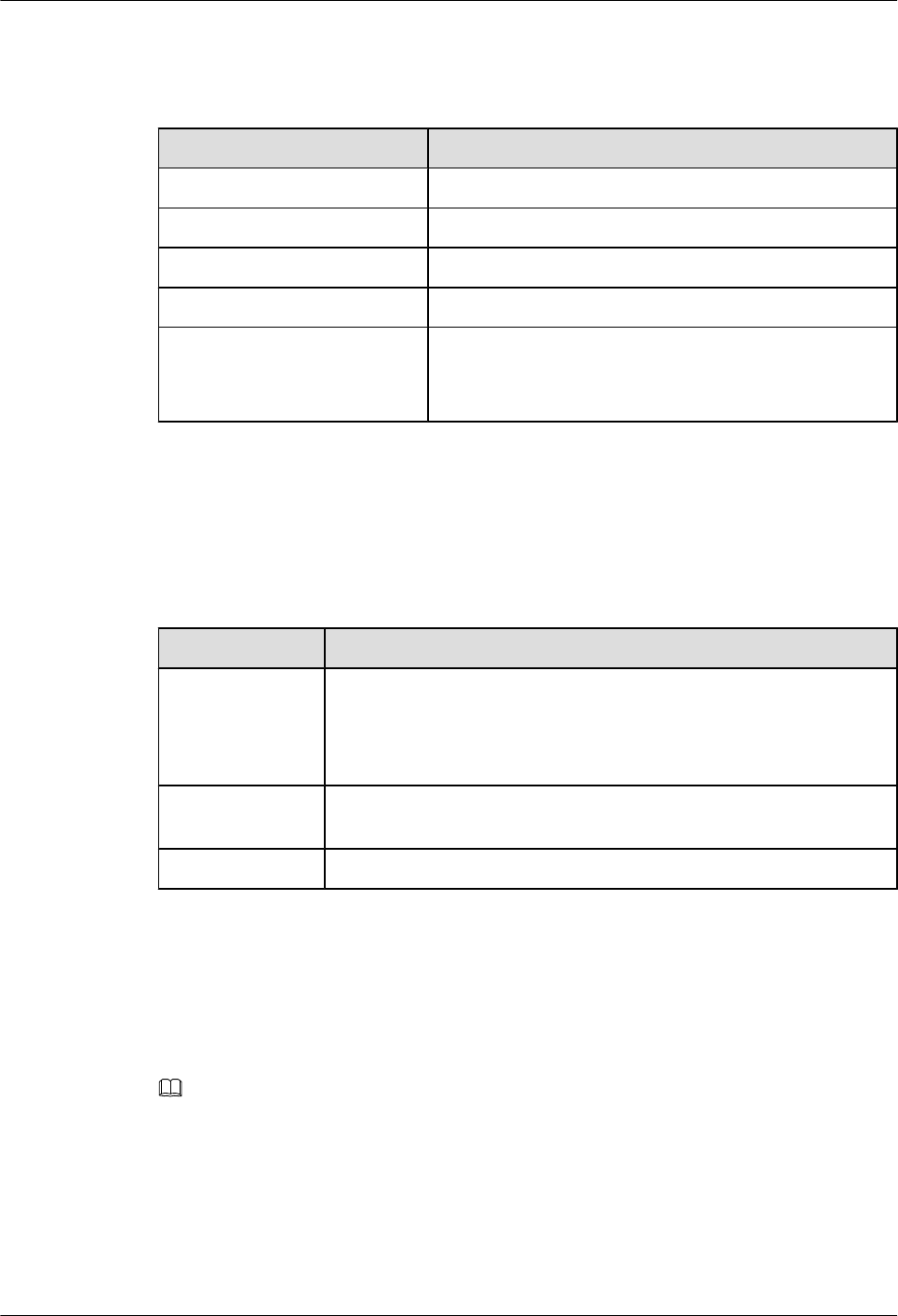
Interface Attributes
Table 5-68 ISDN S/T interface attributes
Item Description
Connector RJ45
Standards compliance ITU-T I.430, Q.921, Q.931
Rate 192 kbit/s
Bandwidth 0 to 100 MHz
Cable lTE: standard ISDN S/T interface cables (straight-
through cables)
lNT: ISDN S/T interface crossover cables
Technical Specifications
Table 5-69 describes the technical specifications of the 2BST.
Table 5-69 Technical specifications of the 2BST
Item Specification
Dimensions
(depth x width x
height)
2BST (SIC): 223.5 mm x 100.1 mm x 19.82 mm (8.8 in. x 3.94 in. x
0.78 in.)
2BST (WSIC): 223.5 mm x 201 mm x 19.82 mm (8.8 in. x 7.92 in. x
0.78 in.)
Maximum power
consumption
16.8 W
Weight 0.3 kg (0.66 lb)
5.5.2 4FXS1FXO-4-Port FXS and 1-Port FXO Voice Interface Card
The 4FXS1FXO is the voice module on the AR routers. It provides five RJ11 interfaces,
including four POTS FXS interfaces and one POTS FXO interface.
NOTE
lAn FXS interface is a simulated subscriber line interface and provides access to AT0 loop trunk of the
analog phone, fax, and telephone exchange.
lAn FXO interface is a loop trunk interface and provides access to the telephone exchange by using
regular subscriber lines.
Functions and Applications
Huawei AR1200-S&2200-S Series Enterprise Routers
Hardware Description 5 Cards
Issue 03 (2012-04-20) Huawei Proprietary and Confidential
Copyright © Huawei Technologies Co., Ltd.
77
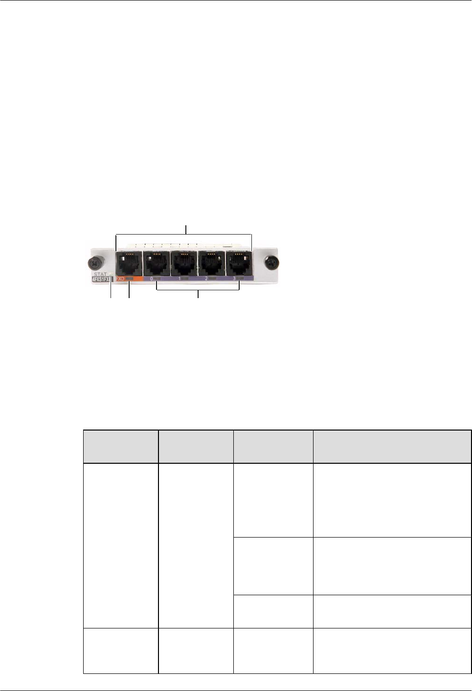
Functions
The 4FXS1FXO works with the SRU to implement the voice call function. The first FXS
interface works with an FXO interface to implement the power failure survival function.
Applications
The 4FXS1FXO can be installed into the SIC slot of the AR2220-S.
Panel and Interfaces
Figure 5-22 shows the appearance of the 4FXS1FXO.
Figure 5-22 Appearance of the 4FXS1FXO
a
1 2 3
Buttons and Indicators on the Panel
Table 5-70 describes the buttons and indicators on the 4FXS1FXO panel.
Table 5-70 Buttons and indicators on the 4FXS1FXO panel
Number in
Figure 5-22
Indicator Color Description
1STAT Green If the indicator blinks once 2s (0.5
Hz), the system is running properly.
If the indicator blinks once 0.25s (4
Hz), the system is powering on or
restarting.
Red If the indicator is red, a fault that
affects services occurs and cannot be
rectified automatically. The fault
needs to be rectified manually.
Off If the indicator is off, the software is
not running or is being reset.
2 ACT (interface
status
indicator)
Green If the indicator is steady on, the FXO
channel is being occupied by a call.
Huawei AR1200-S&2200-S Series Enterprise Routers
Hardware Description 5 Cards
Issue 03 (2012-04-20) Huawei Proprietary and Confidential
Copyright © Huawei Technologies Co., Ltd.
78
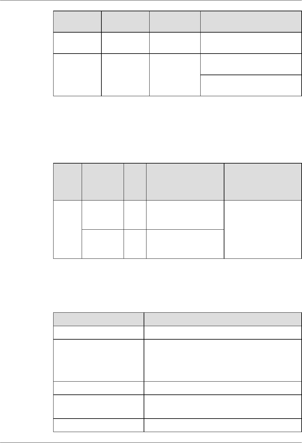
Number in
Figure 5-22
Indicator Color Description
If the indicator is off, the FXO
channel is idle.
3 ACT (interface
status
indicator)
Green If the indicator is steady on, the FXS
channel is being occupied by a call.
If the indicator is off, the FXS
channel is idle.
Interfaces
Table 5-71 describes the types and functions of interfaces on the 4FXS1FXO.
Table 5-71 Types and functions of interfaces on the 4FXS1FXO
Letter
in
Figure
5-22
Name Qua
ntity
Description Cable Type
a FXS (RJ11) 4 The POTS voice FXS
interface uses regular
telephone lines.
6.11 Regular Telephone
Lines
FXO (RJ11) 1 The POTS voice FXO
interface uses regular
telephone lines.
Interface Attributes
Table 5-72 Attributes of FXS/FXO (RJ11) interfaces
Attribute Description
Connector type RJ11
Standards compliance ITU Q.512 for FXS interfaces
ITU Q.552 for FXO interfaces
ITU K.20 for protection against overcurrent and
overvoltage
Cable type Regular telephone line
Dialing mode DTMF in accordance with GB3378
Pulse dialing
Bandwidth 300 Hz to 3400 Hz
Huawei AR1200-S&2200-S Series Enterprise Routers
Hardware Description 5 Cards
Issue 03 (2012-04-20) Huawei Proprietary and Confidential
Copyright © Huawei Technologies Co., Ltd.
79
Technical Specifications
Table 5-73 describes the technical specifications of the 4FXS1FXO.
Table 5-73 Technical specifications of the 4FXS1FXO
Item Specification
Dimensions
(Depth x Width x
Height)
223.5 mm x 100.1 mm x 19.82 mm (8.8 in. x 3.94 in. x 0.78 in.)
Maximum power
consumption
12.78 W
Weight 0.3 kg (0.66 lb)
5.5.3 16/32/64/128-Channel DSP Module
The 16/32/64/128-channel DSP module is a VoIP voice processing DIMM.
Functions and Applications
Functions
The 16/32/64/128-channel DSP module provides the voice over IP (VoIP) functions, including:
lProcesses the dial tone.
lParses telephone numbers.
lGenerates interactive voice response (IVR) and voice signal.
lEncodes, decodes, and converts voice.
lImplements voice conferences and echo canceler (EC).
lProcesses IP packets.
Applications
The 16/32/64/128-channel DSP module is installed into the DSP DIMM of the main control
board on the AR2220-S.
CAUTION
Only the DSP module supported by the product can be inserted into the DSP DIMM slot. The
DDR3 memory board or unsupported DIMMs cannot be inserted; otherwise, the device may be
damaged or does not function properly.
Huawei AR1200-S&2200-S Series Enterprise Routers
Hardware Description 5 Cards
Issue 03 (2012-04-20) Huawei Proprietary and Confidential
Copyright © Huawei Technologies Co., Ltd.
80
Technical Specifications
Table 5-74 shows the technical specifications of the 16/32/64/128-channel DSP module.
Table 5-74 Technical specifications of the 16/32/64/128-channel DSP module
Item Specification
Maximum power
consumption
2.89 W
Weight 0.05 kg (0.11 lb)
5.6 xDSL Interface Card
This section describes the types, functions, applications, appearance, interfaces, and technical
specifications of the xDSL/xPON interface card.
5.6.1 ADSL-A/M and ADSL-B-1-Port-ADSL2+ ANNEX A/M and B
WAN Interface Card
The ADSL-A/M and ADSL-B are the ADSL2/ADSL2+ service access modules on the AR
routers and support ADSL2+ Annex A, Annex B, and Annex M specifications.
NOTE
lThe ADSL-A/M supports both Annex A and Annex M.
lThe ADSL-B supports Annex B.
Table 5-75 describes the comparison between Annex A, Annex B, and Annex M.
Table 5-75 Comparison between Annex A, Annex B, and Annex M
Card Name Usage Scenario
Annex A Annex A is applied to ADSL over POTS and compatible with POTS
services.
Annex B Annex B is applied to ADSL over ISDN and compatible with ISDN
services.
Huawei AR1200-S&2200-S Series Enterprise Routers
Hardware Description 5 Cards
Issue 03 (2012-04-20) Huawei Proprietary and Confidential
Copyright © Huawei Technologies Co., Ltd.
81
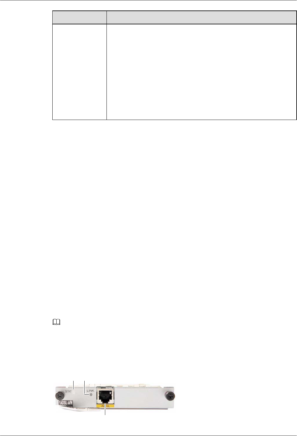
Card Name Usage Scenario
Annex M Annex M expands the upstream frequency band of ADSL and provides
a higher upstream transmission rate.
G.992.3 and G.992.5 each define Annex M:
lAnnex M defined in G.992.3 and Annex M defined in G.992.5 have
the same upstream frequency band.
lThey have different downstream frequency bands:
–The maximum downstream frequency band of Annex M defined
in G.992.3 is 1104 kHz.
–The maximum downstream frequency band of Annex M defined
in G.992.5 is 2208 kHz.
Functions and Applications
Functions
The ADSL-A/M and ADSL-B each provide 1-channel ADSL/ADSL2+ access, provide
independent CPU and management interfaces, and support ADSL2+ Annex A, Annex B, and
Annex M specifications.
The ADSL-A/M or ADSL-B consists of the following modules:
lCPU control module: manages the system and loads programs.
lADSL2+ module: implements ADSL2+ modulation and demodulation on CPEs.
lSGMII upstream module: provides one SGMII upstream interface to communicate with
the active and standby SRUs.
lPower supply module: conducts power from backplane to card.
lClock module: provides two types of working clocks for cards.
Applications
The ADSL-A/M and ADSL-B can be installed into the SIC slot of the AR1200-S and AR2220-
S.
Panel and Interfaces
NOTE
The ADSL-A/M and ADSL-B panels are identical except for having different silkscreens. The following
describes the panel and Interfaces of the ADSL-A/M.
Figure 5-23 shows the appearance of the ADSL-A/M.
Figure 5-23 Appearance of the ADSL-A/M
1 2
a
Huawei AR1200-S&2200-S Series Enterprise Routers
Hardware Description 5 Cards
Issue 03 (2012-04-20) Huawei Proprietary and Confidential
Copyright © Huawei Technologies Co., Ltd.
82
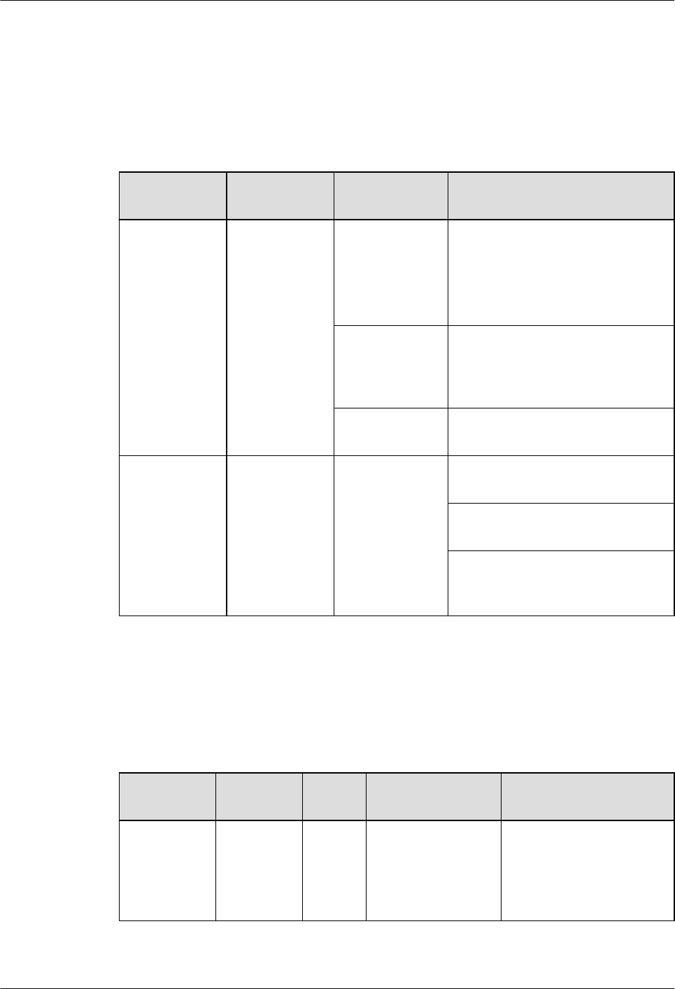
Buttons and Indicators on the Panel
Table 5-76 describes the buttons and indicators on the ADSL-A/M panel.
Table 5-76 Buttons and indicators on the ADSL-A/M panel
Number in
Figure 5-23
Indicator Color Description
1STAT Green If the indicator blinks once 2s (0.5
Hz), the system is running properly.
If the indicator blinks once 0.25s (4
Hz), the system is powering on or
restarting.
Red If the indicator is red, a fault that
affects services occurs and cannot be
rectified automatically. The fault
needs to be rectified manually.
Off If the indicator is off, the software is
not running or is being reset.
2 LINK Green If the indicator is steady on, the DSL
channel has been activated.
If the indicator is off, the DSL
channel is not activated.
If the indicator blinks once 0.25s (4
Hz), the DSL channel is being
activated.
Interfaces
Table 5-77 describes the types and functions of interfaces on the ADSL-A/M.
Table 5-77 Types and functions of interfaces on the ADSL-A/M
Letter in
Figure 5-23
Name Quanti
ty
Description Cable Type
a ADSL2+
(RJ11)
1 The ADSL-A/M
provides one RJ11
interface, which
supports regular
telephone lines.
6.11 Regular Telephone
Lines
Huawei AR1200-S&2200-S Series Enterprise Routers
Hardware Description 5 Cards
Issue 03 (2012-04-20) Huawei Proprietary and Confidential
Copyright © Huawei Technologies Co., Ltd.
83
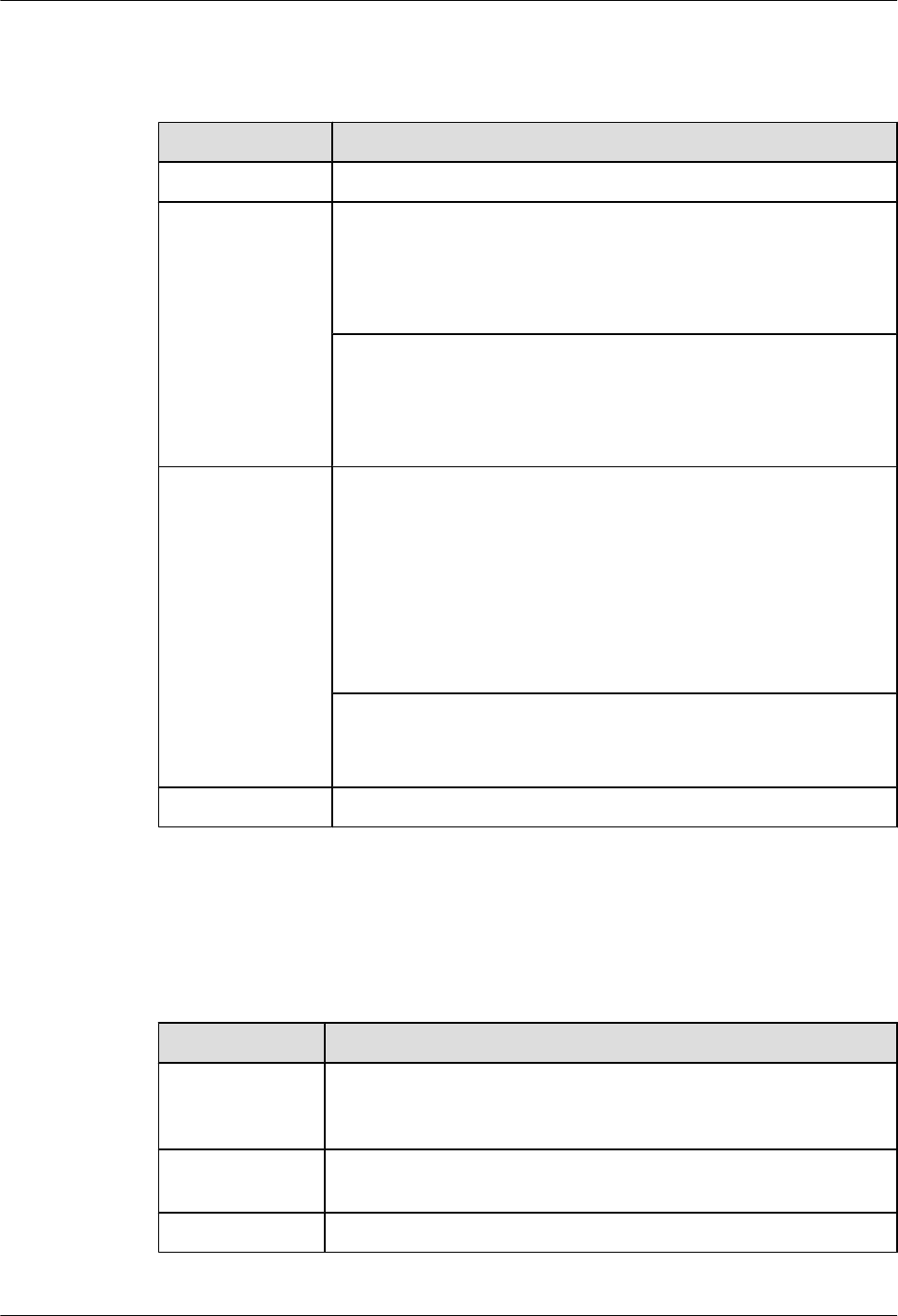
Interface Attributes
Table 5-78 Attributes of ADSL2/ADSL2+ interfaces
Attribute Description
Connector type RJ11
Standards
compliance
ADSL-A/M:
ITU-T 992.1 G.DMT
ITU-T 992.3
ITU-T 992.5
ADSL-B:
ITU-T 992.1 G.DMT ANSI T1.413 Issue 2
ITU-T 992.3
ITU-T 992.5
Transmission rate ADSL-A/M:
lADSL full rate mode (ITU-T 992.1 G.DMT): a downstream
transmission rate of 8 Mbit/s and an upstream transmission rate of
1024 kbit/s
lADSL2 full rate mode (ITU-T 992.3): a downstream transmission
rate of 12 Mbit/s and an upstream transmission rate of 1024 kbit/s
lADSL2+ full rate mode (ITU-T 992.5): a downstream transmission
rate of 24 Mbit/s and an upstream transmission rate of 1024 kbit/s
ADSL-B:
A downstream transmission rate of 8 Mbit/s and an upstream
transmission rate of 1024 kbit/s
Cable type Regular telephone line
Technical Specifications
Table 5-79 describes the technical specifications of the ADSL-A/M and ADSL-B.
Table 5-79 Technical specifications of the ADSL-A/M and ADSL-B
Item Specification
Dimensions
(Depth x Width x
Height)
223.5 mm x 100.1 mm x 19.82 mm (8.8 in. x 3.94 in. x 0.78 in.)
Maximum power
consumption
5.4 W
Weight 0.3 kg (0.66 lb)
Huawei AR1200-S&2200-S Series Enterprise Routers
Hardware Description 5 Cards
Issue 03 (2012-04-20) Huawei Proprietary and Confidential
Copyright © Huawei Technologies Co., Ltd.
84

5.6.2 4G.SHDSL-1-Port-4-Channel G.SHDSL WAN Interface Card
The 4G.SHDSL is the G.SHDSL service access module on the AR routers.
G.Single-Pair High-Speed Digital Subscriber Line (G.SHDSL) uses trellis coded pulse
amplitude modulation (TCPAM), provides up to 5.696 Mbit/s symmetric data rates, and supports
2/3/4-pair binding. The transmission rate can automatically adapt according to the line length
and conditions. G.SHDSL provides a longer transmission distance than ADSL.
Functions and Applications
Functions
The 4G.SHDSL provides 4-channel G.SHDSL access and the independent CPU as well as
management interfaces.
The 4G.SHDSL consists of the following modules:
lCPU control module: manages the system and loads programs.
lG.SHDSL module: processes G.SHDSL services on CPEs.
lGE upstream module: provides one upstream interface to communicate with the active and
standby SRUs.
lPower supply module: conducts power from backplane to card.
lClock module: provides three types of working clocks for cards.
Applications
The 4G.SHDSL can be installed into the SIC slot of the AR1200-S and AR2220-S.
Panel and Interfaces
Figure 5-24 shows the appearance of the 4G.SHDSL.
Figure 5-24 Appearance of the 4G.SHDSL
1 2 3
a
Buttons and Indicators on the Panel
Table 5-80 describes the buttons and indicators on the 4G.SHDSL panel.
Huawei AR1200-S&2200-S Series Enterprise Routers
Hardware Description 5 Cards
Issue 03 (2012-04-20) Huawei Proprietary and Confidential
Copyright © Huawei Technologies Co., Ltd.
85

Table 5-80 Buttons and indicators on the 4G.SHDSL panel
Number in
Figure 5-24
Indicator Color Description
1STAT Green If the indicator blinks once 2s (0.5
Hz), the system is running properly.
If the indicator blinks once 0.25s (4
Hz), the system is powering on or
restarting.
Red If the indicator is red, a fault that
affects services occurs and cannot be
rectified automatically. The fault
needs to be rectified manually.
Off If the indicator is off, the software is
not running or is being reset.
2 LINK Green If the indicator is steady on, the four
DSL channels have been activated.
If the indicator is off, the four DSL
channels have not been activated.
lIf the indicator is on for 0.25
seconds and blinks three times in
the next 0.75 seconds, the DSL
channel has been activated.
lIf the indicator is on for 0.5
seconds and blinks twice in the
next 0.5 seconds, the two DSL
channels have been activated.
lIf the indicator is on for 0.75
seconds and blinks in the next
0.25 seconds, the three DSL
channels have been activated.
3ACT Yellow If the indicator is blinking, data is
being transmitted or received.
If the indicator is off, no data is being
transmitted or received.
Interfaces
Table 5-81 describes the types and functions of interfaces on the 4G.SHDSL.
Huawei AR1200-S&2200-S Series Enterprise Routers
Hardware Description 5 Cards
Issue 03 (2012-04-20) Huawei Proprietary and Confidential
Copyright © Huawei Technologies Co., Ltd.
86
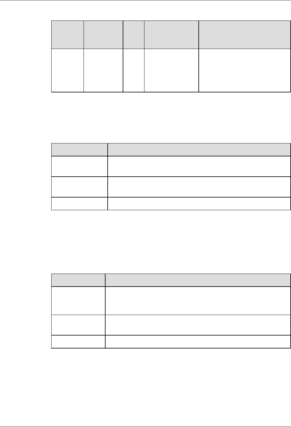
Table 5-81 Types and functions of interfaces on the 4G.SHDSL
Letter in
Figure
5-24
Name Qua
ntity
Description Cable Type
a G.SHDSL
(RJ45)
1 The 4G.SHDSL
provides one RJ45
interface, which
supports standard
network cables.
6.9 4G.SHDSL Cables or 6.5
Network Cable
Interface Attributes
Table 5-82 Attributes of G.SHDSL interfaces
Attribute Description
Connector type One RJ45 connector on one end and four RJ11 connectors on the other
end
Standards
compliance
G.SHDSL.bit
Transmission rate 5.696 Mbit/s per pair
Technical Specifications
Table 5-83 describes the technical specifications of the 4G.SHDSL.
Table 5-83 Technical specifications of the 4G.SHDSL
Item Specification
Dimensions
(Depth x Width x
Height)
223.5 mm x 100.1 mm x 19.82 mm (8.8 in. x 3.94 in. x 0.78 in.)
Maximum power
consumption
8.2 W
Weight 0.35 kg (0.78 lb)
5.6.3 1PON (1-Port GPON/EPON Dual-Mode Interface Card)
The 1PON card is the EPON/GPON auto-sensing module on the AR routers.
Huawei AR1200-S&2200-S Series Enterprise Routers
Hardware Description 5 Cards
Issue 03 (2012-04-20) Huawei Proprietary and Confidential
Copyright © Huawei Technologies Co., Ltd.
87

NOTE
1 port: There are two ports on the 1PON card, one of which is the backup port. Therefore, the 1PON card
is also called the 1PON.
The 1PON card functions as the ONU of the EPON/GPON system:
lReceives cells broadcast in TDM mode at a downlink rate of 1.25 Gbit/s (EPON) or 2.488
Gbit/s (GPON).
lSupports burst transmission in TDMA mode at an uplink rate of 1.25 Gbit/s (EPON) or
1.244 Gbit/s (GPON).
Functions and Applications
Functions
The 1PON card works with the main control board and supports two PON SFP uplink interfaces.
The 1PON card has the following functions:
lSupports OLT clock synchronization but not the 1588 function.
lSupports EPON/GPON but not GE.
lSupports the DyingGasp function.
lSupports rogue ONT detection and isolation.
lDetects the receiving optical power.
lSupports delayed reset.
Applications
The 1PON card is installed into the SIC slot of the AR1200-S and AR2220-S.
Panel and Interfaces
Figure 5-25 shows the appearance of the 1PON panel.
Figure 5-25 Appearance of the 1PON panel
1
a
2 3 2 3
Buttons and Indicators on the Panel
Table 5-84 describes the buttons and indicators on the 1PON panel.
Huawei AR1200-S&2200-S Series Enterprise Routers
Hardware Description 5 Cards
Issue 03 (2012-04-20) Huawei Proprietary and Confidential
Copyright © Huawei Technologies Co., Ltd.
88
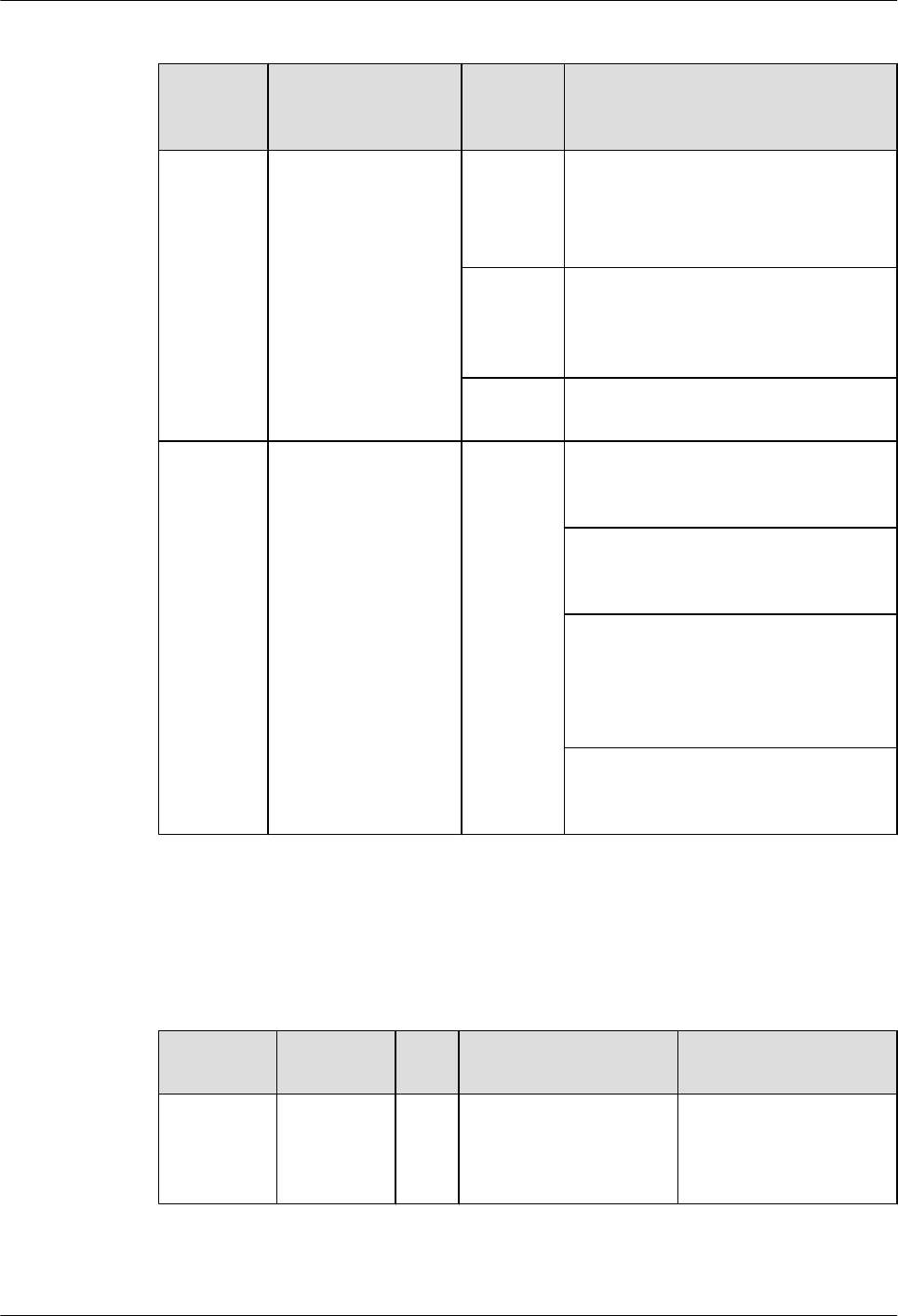
Table 5-84 Buttons and indicators on the 1PON panel
Number
in Figure
5-25
Indicator Color Description
1STAT Green If the indicator blinks once 2s (0.5 Hz),
the system is running properly.
If the indicator blinks once 0.25s (4 Hz),
the system is powering on or restarting.
Red If the indicator is red, a fault that affects
services occurs and cannot be rectified
automatically. The fault needs to be
rectified manually.
Off If the indicator is off, the software is not
running or is being reset.
2 and 3 PON interface
indicators:
lThe LINK
indicator indicates
whether the PON
card is requesting
data transmission.
lThe AUTH
indicator indicates
the authentication
status.
Green If both the LINK indicator and AUTH
indicator are steady on, the 1PON card is
registered successfully.
If the LINK indicator is steady on and the
AUTH indicator blinks once 0.25s (4
Hz), the 1PON card is being registered.
If both the LINK indicator and AUTH
indicator blink once 0.25s (4 Hz), the
1PON card keeps requesting data
transmission. When this occurs, the
1PON card is a rogue ONU.
If both the LINK indicator and AUTH
indicator are off, the 1PON card does not
request data transmission.
Interfaces
Table 5-85 describes the types and functions of interfaces on the 1PON card.
Table 5-85 Types and functions of interfaces on the 1PON card
Letter in
Figure 5-25
Name Qua
ntity
Description Cable Type
a PON
interface
2 The 1PON card provides
EPON/GPON interfaces
that are connected using
SC/PC fibers.
6.6 Optical Fiber
Huawei AR1200-S&2200-S Series Enterprise Routers
Hardware Description 5 Cards
Issue 03 (2012-04-20) Huawei Proprietary and Confidential
Copyright © Huawei Technologies Co., Ltd.
89
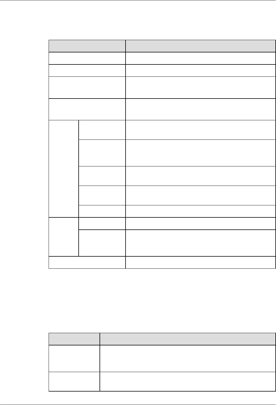
Interface Attributes
Table 5-86 Attributes of the SFP optical module supported by the PON optical interface
Attribute Description
Connector type SC/PC connector (SFP encapsulation)
Transport mode Single-mode bidirectional
Transmission rate lDownstream transmission rate of 2488 Mbit/s
lUpstream transmission rate of 1244 Mbit/s
Standards compliance ITU-T G.984.2 CLASS B+
ITU-T G.984.5 WBF
Sending
end
Center
wavelength
1290 nm to 1330 nm
Average
transmitting
optical power
0.5 dBm to 5 dBm
Average turn-off
optical power
-45 dBm
Side-mode
suppression ratio
30 dB
Extinction ratio 10 dB to 15 dB
Receivin
g end
Overload power -8 dBm
Input
wavelength
range
1480 nm to 1500 nm
Operating temperature 0°C to 70°C
Technical Specifications
Table 5-87 describes the technical specifications of the 1PON card.
Table 5-87 Technical specifications of the 1PON card
Item Specification
Dimensions
(depth x width x
height)
223.5 mm x 100.1 mm x 19.82 mm
Maximum power
consumption
8.72 W
Huawei AR1200-S&2200-S Series Enterprise Routers
Hardware Description 5 Cards
Issue 03 (2012-04-20) Huawei Proprietary and Confidential
Copyright © Huawei Technologies Co., Ltd.
90

Item Specification
Weight 0.3 kg
5.6.4 VDSL (1-Port VDSL2 over POTS WAN Interface Card)
The VDSL interface card provides an interface for VDSL2 access.
Functions and Applications
Functions
The VDSL interface card is used for packet switching and device management. It supports the
following functions:
lWorks in VDSL2 mode that complies with ITU-T G.993.2 and supports profile 17a defined
in G.993.2.
lRolls back to ADSL2+ mode that complies with G.992.5.
lSupports temperature and power measurement.
lSends a dying gasp alarm in the case of a power failure.
The VDSL interface card consists of the following modules:
lADSL2/VDSL2 socket: implements ADSL2/VDSL2 modulation and demodulation on
customer premises equipment (CPE).
lStorage module: stores data and programs on the interface card.
lGE uplink interface module: provides a GE uplink interface to receive and transmit data.
The SRU manages the interface through this GE interface.
lTemperature and power module: measures temperature and power on the interface card.
lClock resetting module: provides signals to reset the system clock.
Applications
The VDSL interface card can be installed in the SIC slot on the AR1200-S and AR2220-S
chassis.
Panel and Interfaces
Figure 5-26 shows the appearance of the VDSL interface card.
Figure 5-26 VDSL panel
12
a
Huawei AR1200-S&2200-S Series Enterprise Routers
Hardware Description 5 Cards
Issue 03 (2012-04-20) Huawei Proprietary and Confidential
Copyright © Huawei Technologies Co., Ltd.
91
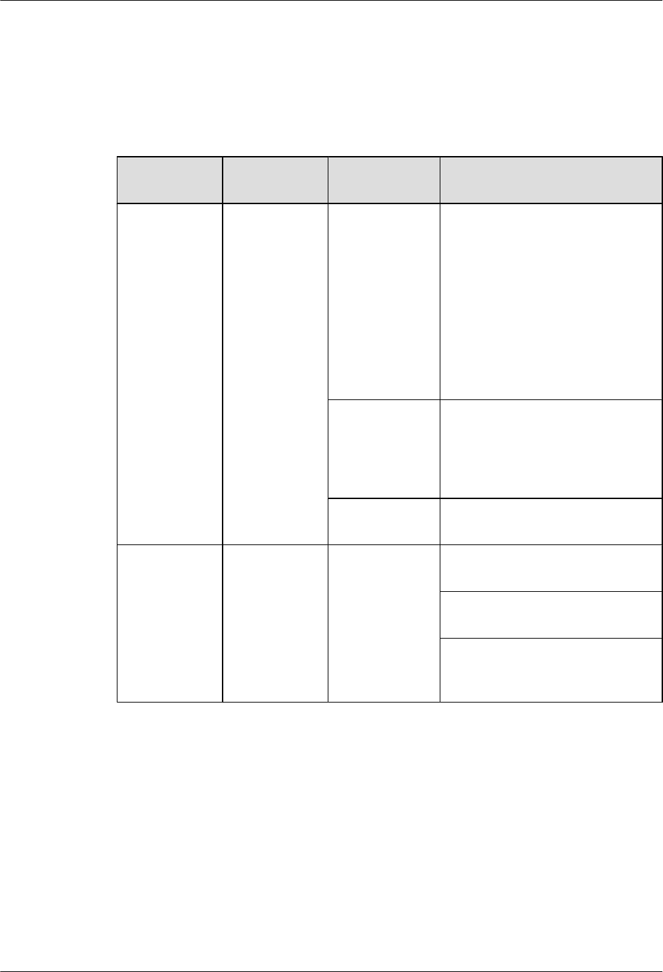
Buttons and Indicators on the Panel
Table 5-88 describes the buttons and indicators on the VDSL panel.
Table 5-88 Buttons and indicators on the VDSL panel
Number in
Figure 5-26
Indicator Color Description
1STAT Green If the indicator is steady on, the
router has been powered on, but the
system software is not running.
If the indicator blinks once every 2s
(0.5 Hz), the system is running
properly.
If the indicator blinks once every
0.25s (4 Hz), the system is loading
software after power-on or is
restarting.
Red If the indicator is steady on, a fault
that affects services has occurred
and cannot be rectified
automatically. The fault needs to be
rectified manually.
Off If the indicator is off, the software is
not running or is being reset.
2 LINK Green If the indicator is steady on, the
VDSL channel has been activated.
If the indicator is off, the VDSL
channel has not been activated.
If the indicator blinks once every
0.25s (4 Hz), the VDSL channel is
being activated.
Interfaces
Table 5-89 describes the types and functions of interfaces on the VDSL interface card.
Huawei AR1200-S&2200-S Series Enterprise Routers
Hardware Description 5 Cards
Issue 03 (2012-04-20) Huawei Proprietary and Confidential
Copyright © Huawei Technologies Co., Ltd.
92
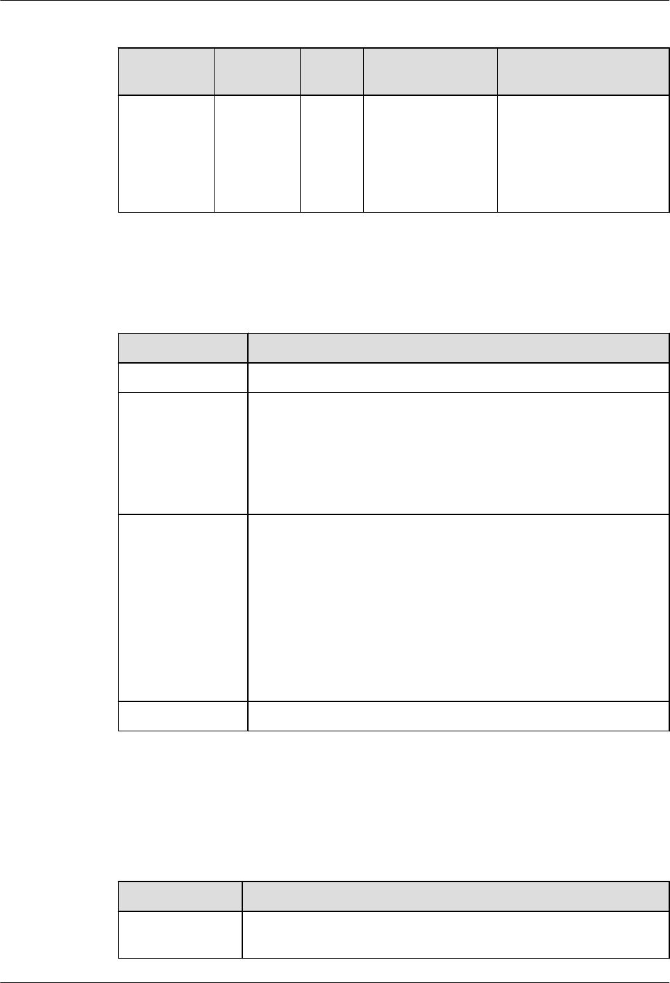
Table 5-89 Types and functions of interfaces on the VDSL interface card
Letter in
Figure 5-26
Name Quanti
ty
Description Cable Type
a VDSL2
(RJ11)
1 The VDSL interface
card provides an
RJ11 interface,
which connects to a
DSLAM through a
telephone cable.
6.11 Regular Telephone
Lines
Interface Attributes
Table 5-90 VDSL interface attributes
Item Description
Connector RJ11
Standards
compliance
VDSL standards:
ITU-T 993.2
ITU-T 992.5
ITU-T 992.3
ITU-T 992.1 G.DMT
Rate lADSL2+ full rate mode (ITU-T 992.3): a downstream transmission
rate of 12 Mbit/s and an upstream transmission rate of 1 Mbit/s
lVDSL2 mode (ITU-T 993.2): a downstream transmission rate of
100 Mbit/s and an upstream transmission rate of 50 kbit/s
lADSL2 full rate mode (ITU-T 992.5): a downstream transmission
rate of 24 Mbit/s and an upstream transmission rate of 1 Mbit/s
lADSL full rate mode (ITU-T 992.1 G.DMT): a downstream
transmission rate of 8 Mbit/s and an upstream transmission rate of
1 Mbit/s
Cable type Telephone cable
Technical Specifications
Table 5-91 describes the technical specifications of the VDSL interface card.
Table 5-91 Technical specifications of the VDSL interface card
Parameter Description
Dimensions (W x
D x H)
100.1 mm x 223.5 mm x 19.82 mm
Huawei AR1200-S&2200-S Series Enterprise Routers
Hardware Description 5 Cards
Issue 03 (2012-04-20) Huawei Proprietary and Confidential
Copyright © Huawei Technologies Co., Ltd.
93

Parameter Description
Maximum power
consumption
7.6 W
Weight 0.2 kg
Huawei AR1200-S&2200-S Series Enterprise Routers
Hardware Description 5 Cards
Issue 03 (2012-04-20) Huawei Proprietary and Confidential
Copyright © Huawei Technologies Co., Ltd.
94

6 Cables
About This Chapter
This chapter describes the cables used by the AR routers, including the structures and technical
specifications of the cables.
6.1 AC Power Cable
An AC power cable transmits AC power to the switch.
6.2 DC Power Cables
A DC power cable transmits DC power to the switch.
6.3 Ground Cable
A ground cable protects the device from lightning strike and electromagnetic interference.
6.4 Console Cable
A console cable is used to debug or maintain a local device.
6.5 Network Cable
A network cable subtends devices, enables a device to communication with other network
devices, and allows users to locally or remotely maintain the device.
6.6 Optical Fiber
An optical fiber connects the optical interface of a device to an upstream device or optical
network terminal.
6.7 E1/T1 Trunk Cables
This section describes the structure and technical specifications of the E1/T1 trunk cable.
6.8 Synchronous/Asynchronous Serial Interface Cables
This section describes the categories, structure, and technical specifications of the synchronous/
asynchronous serial interface cable.
6.9 4G.SHDSL Cables
This section describes the structure and technical specifications of the 4G.SHDSL cable.
6.10 ISDN-ST Cables
This section describes the categories, structure, and technical specifications of the ISDN-ST
cable.
6.11 Regular Telephone Lines
Huawei AR1200-S&2200-S Series Enterprise Routers
Hardware Description 6 Cables
Issue 03 (2012-04-20) Huawei Proprietary and Confidential
Copyright © Huawei Technologies Co., Ltd.
95

This section describes the structure and technical specifications of the regular telephone line.
6.12 8AS Cable
An 8AS cable is connected to an 8AS interface card to commission or maintain the 8AS interface
card.
6.13 3G Antenna
A 3G antenna transmits and receives 3G signals to enable an AR router to communicate with a
3G network.
Huawei AR1200-S&2200-S Series Enterprise Routers
Hardware Description 6 Cables
Issue 03 (2012-04-20) Huawei Proprietary and Confidential
Copyright © Huawei Technologies Co., Ltd.
96

6.1 AC Power Cable
An AC power cable transmits AC power to the switch.
Application
An AC power cable connects the following:
lThe AC input power jack on the chassis
lThe other end is connected to the AC power supply
Appearance
Figure 6-1 shows the appearance of the AC power cable.
Figure 6-1 Appearance of the AC power cable
Specifications
NOTE
The AC power cables used in different countries and regions may have different specifications. The
following are the specifications of the international standard AC power cable.
Table 6-1 lists the specifications of the AC power cable.
Table 6-1 Specifications of the AC power cable
Item Description
Cable type External power cable
Function 250 V AC/10 A complying with international standard
Huawei AR1200-S&2200-S Series Enterprise Routers
Hardware Description 6 Cables
Issue 03 (2012-04-20) Huawei Proprietary and Confidential
Copyright © Huawei Technologies Co., Ltd.
97

Item Description
Connector 1 PI-straight-male
Connector 2 C13-straight-female
Cable type l227 IEC 53 (RVV)-300 V/500 V
lRated voltage: 300 V/500 V
lStandards compliance: 227 IEC 53 (RVV)
Conductor cross-sectional
area
3 x 1.0 mm2 (3 x 0.00155 in.2)
Fireproof level GB18380.1
6.2 DC Power Cables
A DC power cable transmits DC power to the switch.
Applications
A DC power cable connects the following two interfaces:
lInput power jack on the chassis
lOutput power interface on an external power system
NOTE
A black -48 V DC power return wire (RTN) is connected to the RTN(+) end of the DC power supply. A
blue -48 V DC power cable is connected to the NEG(-) end of the DC power supply.
Appearance and Structure
The black -48 V DC power return wire and the blue -48 V DC power cable are shown in Figure
6-2 and Figure 6-3.
Huawei AR1200-S&2200-S Series Enterprise Routers
Hardware Description 6 Cables
Issue 03 (2012-04-20) Huawei Proprietary and Confidential
Copyright © Huawei Technologies Co., Ltd.
98

Figure 6-2 -48 V DC power return wire
Figure 6-3 -48 V DC power cable
Specifications
The technical specifications of a -48 V DC power return wire and a -48 V DC power cable are
the same, as described in Table 6-2.
Huawei AR1200-S&2200-S Series Enterprise Routers
Hardware Description 6 Cables
Issue 03 (2012-04-20) Huawei Proprietary and Confidential
Copyright © Huawei Technologies Co., Ltd.
99

Table 6-2 Specifications of the DC power cables
Item Description
Cable type Power cable
Color Blue for -48 V DC power cable and black for -48 V DC power
return wire
Connector 1 OT
Connector 2 Cord end terminal
Impedance 4.95 Ω/km
Conductor cross-sectional
area
1.2 mm2 (0.00186 in.2)
6.3 Ground Cable
A ground cable protects the device from lightning strike and electromagnetic interference.
Application
A ground cable connects the chassis to the ground.
Appearance
Figure 6-4 shows the appearance of the ground cable.
Figure 6-4 Appearance of the ground cable
Specifications
Table 6-3 lists the specifications of the ground cable.
Huawei AR1200-S&2200-S Series Enterprise Routers
Hardware Description 6 Cables
Issue 03 (2012-04-20) Huawei Proprietary and Confidential
Copyright © Huawei Technologies Co., Ltd.
100
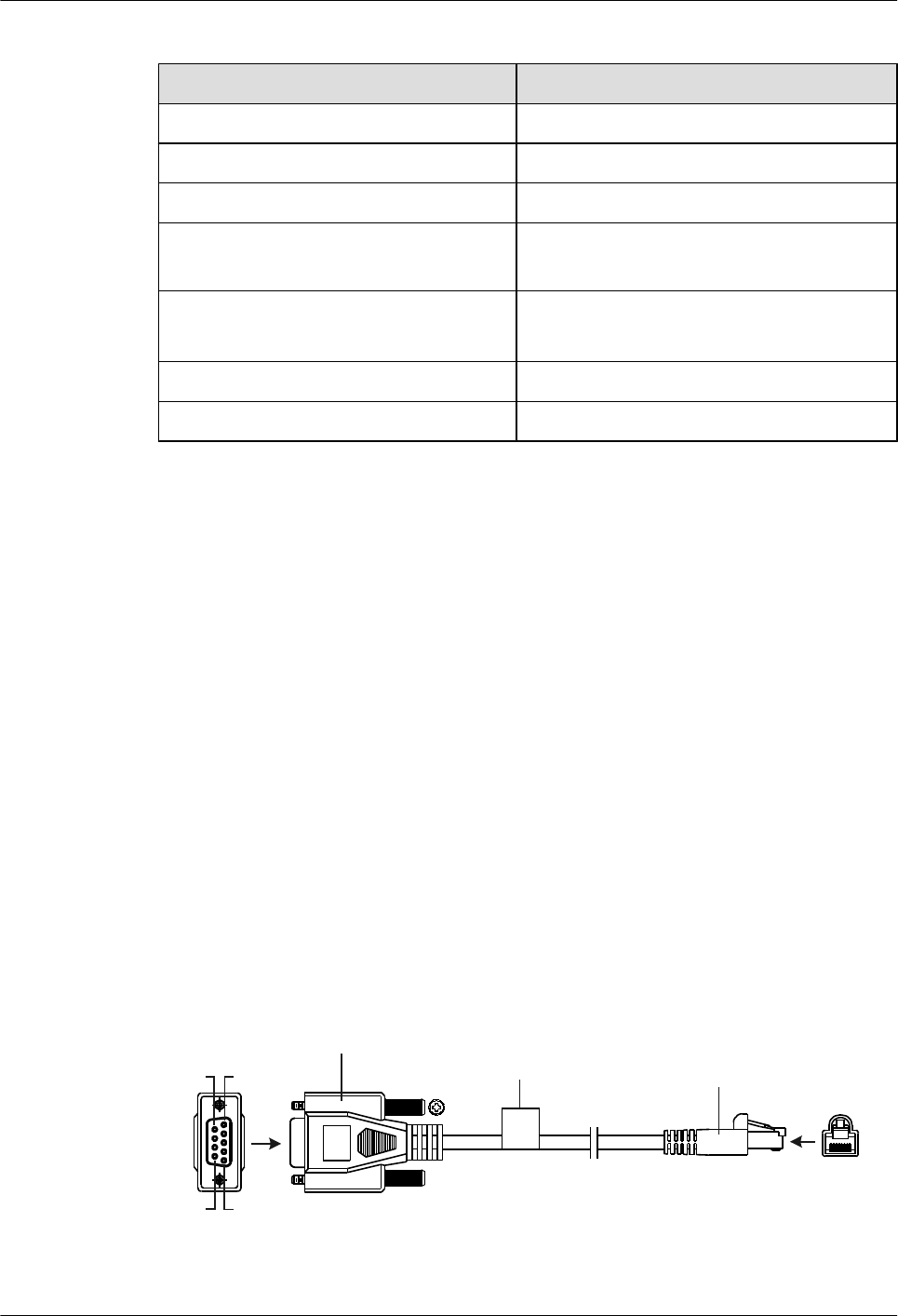
Table 6-3 Specifications of the ground cable
Item Description
Cable type Power cable
Color Green-yellow
Connector type (X1/X2) OT/OT naked crimping terminal
Gauge 10 AWG (cross-sectional area ≈ 5.2 mm2
[0.0081 in.2])
Cable type lStandards compliance: H07Z-K UL3386
lLength: 0.3 m
Maximum current 50.0 A
Fireproof level VW-1, CSA FT1
6.4 Console Cable
A console cable is used to debug or maintain a local device.
Application
A console cable connects the console port of the device to the serial port of an operation terminal
to transmit configuration data. A shielded cable or an unshielded cable can be used according
to the onsite situation.
A console cable connects the device and terminal as follows:
lThe 8-pin RJ45 connector is inserted into the console port of the device.
lThe DB9 male connector is connected to an operation terminal, which is usually a PC.
Appearance and Structure
Figure 6-5 shows the structure of the console cable.
Figure 6-5 Structure of the console cable
X1
Pos.1
Pos.9
Pos.6
Pos.5
X2 1 8
Network port connector
(8-pin, RJ-45)
D-type connector
(9-pin, male)
Label
Huawei AR1200-S&2200-S Series Enterprise Routers
Hardware Description 6 Cables
Issue 03 (2012-04-20) Huawei Proprietary and Confidential
Copyright © Huawei Technologies Co., Ltd.
101
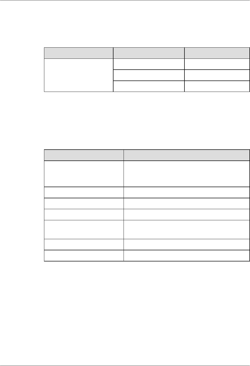
Pin Assignments
Table 6-4 describes the pin assignments of the console cable.
Table 6-4 Pin assignments of the console cable
Connector X1(DB9) X2(RJ45)
Pin assignment 2 3
3 6
5 5
Specifications
Table 6-5 lists the specifications of the console cable.
Table 6-5 Specifications of the console cable
Item Description
Connector type lConnector X1: cable connector, D-type, 9-pin, male
lConnector X2: network interface connector, RJ45, 8-
pin, 8-bit, male
Cable type Twisted pair
Color PANTONE WARM GRAY 1U
Diameter 0.32 mm (0.13 in.)
Gauge 28 AWG (cross-sectional area ≈ 0.08 mm2 [0.0002 in.
2])
Pin 2 pairs
Length 3 m (9.85 ft.)
6.5 Network Cable
A network cable subtends devices, enables a device to communication with other network
devices, and allows users to locally or remotely maintain the device.
Application
A network cable connects a maintenance terminal to the console port on the main control board
for local or remote maintenance.
The network cables are classified into straight-through cables and crossover cables.
Huawei AR1200-S&2200-S Series Enterprise Routers
Hardware Description 6 Cables
Issue 03 (2012-04-20) Huawei Proprietary and Confidential
Copyright © Huawei Technologies Co., Ltd.
102
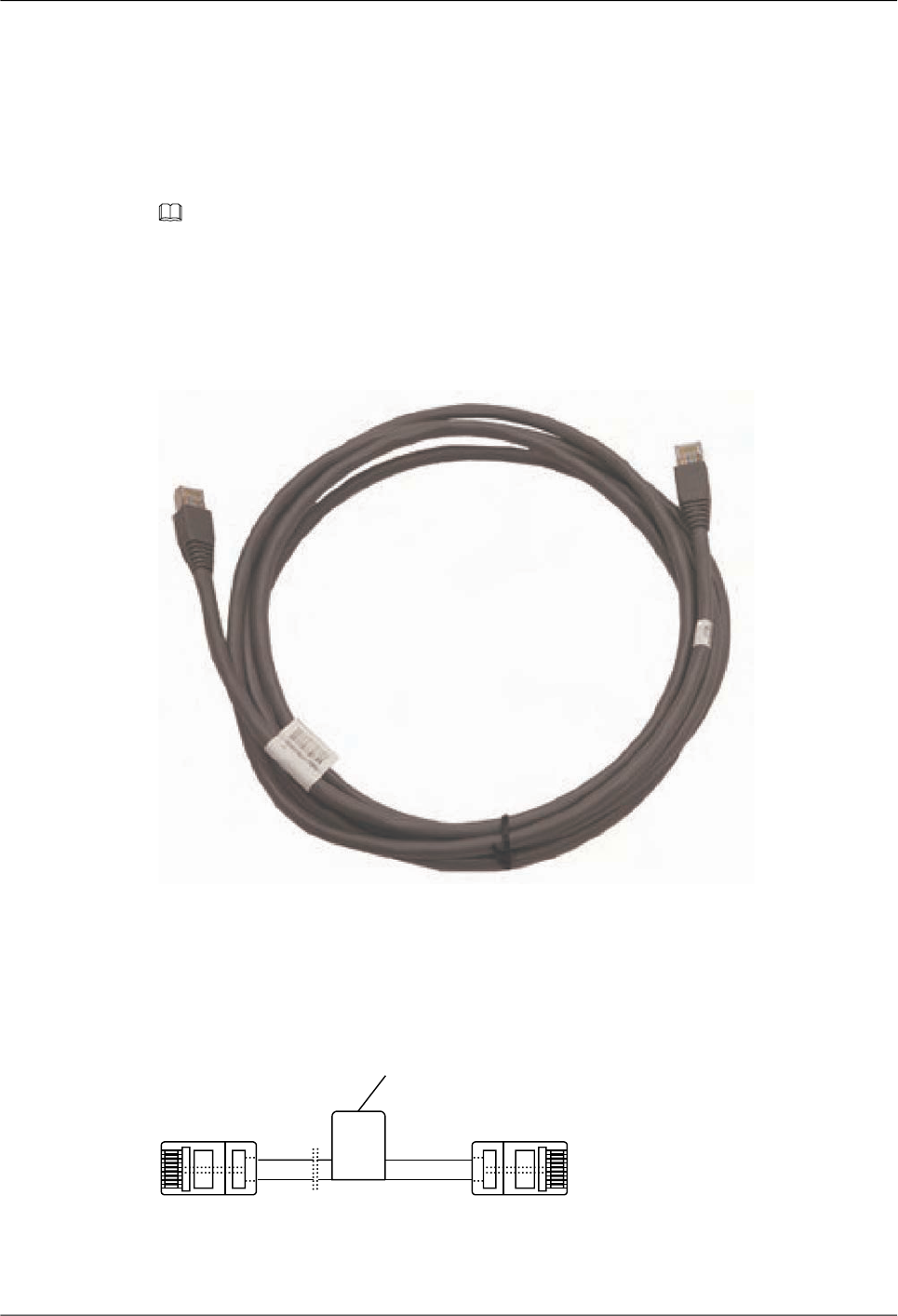
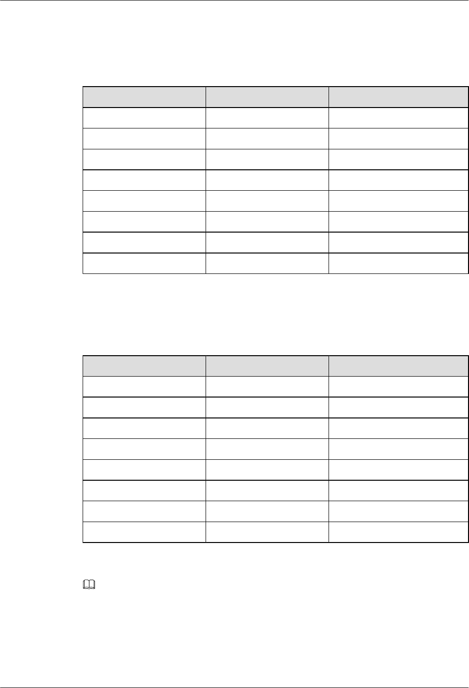
Pin Assignments
Table 6-6 describes the pin assignments of the straight-through cable.
Table 6-6 Pin assignments of the straight-through cable
X1 Pin Tip Color X2 Pin
1White and orange 1
2 Orange 2
3 White and Green 3
4 Blue 4
5 White and Blue 5
6 Green 6
7 White and brown 7
8 Brown 8
Table 6-7 describes the pin assignments of the crossover cable.
Table 6-7 Pin assignments of the crossover cable
X1 Pin Tip Color X2 Pin
1White and orange 3
2 Orange 6
3 White and Green 1
4 Blue 4
5 White and Blue 5
6 Green 2
7 White and brown 7
8 Brown 8
NOTE
To achieve the optimum electrical transmission performance, ensure that the wires connected to pins 1 and 2
and to pins 3 and 6 are twisted pairs.
Specifications
Table 6-8 lists the specifications of the network cable.
Huawei AR1200-S&2200-S Series Enterprise Routers
Hardware Description 6 Cables
Issue 03 (2012-04-20) Huawei Proprietary and Confidential
Copyright © Huawei Technologies Co., Ltd.
104
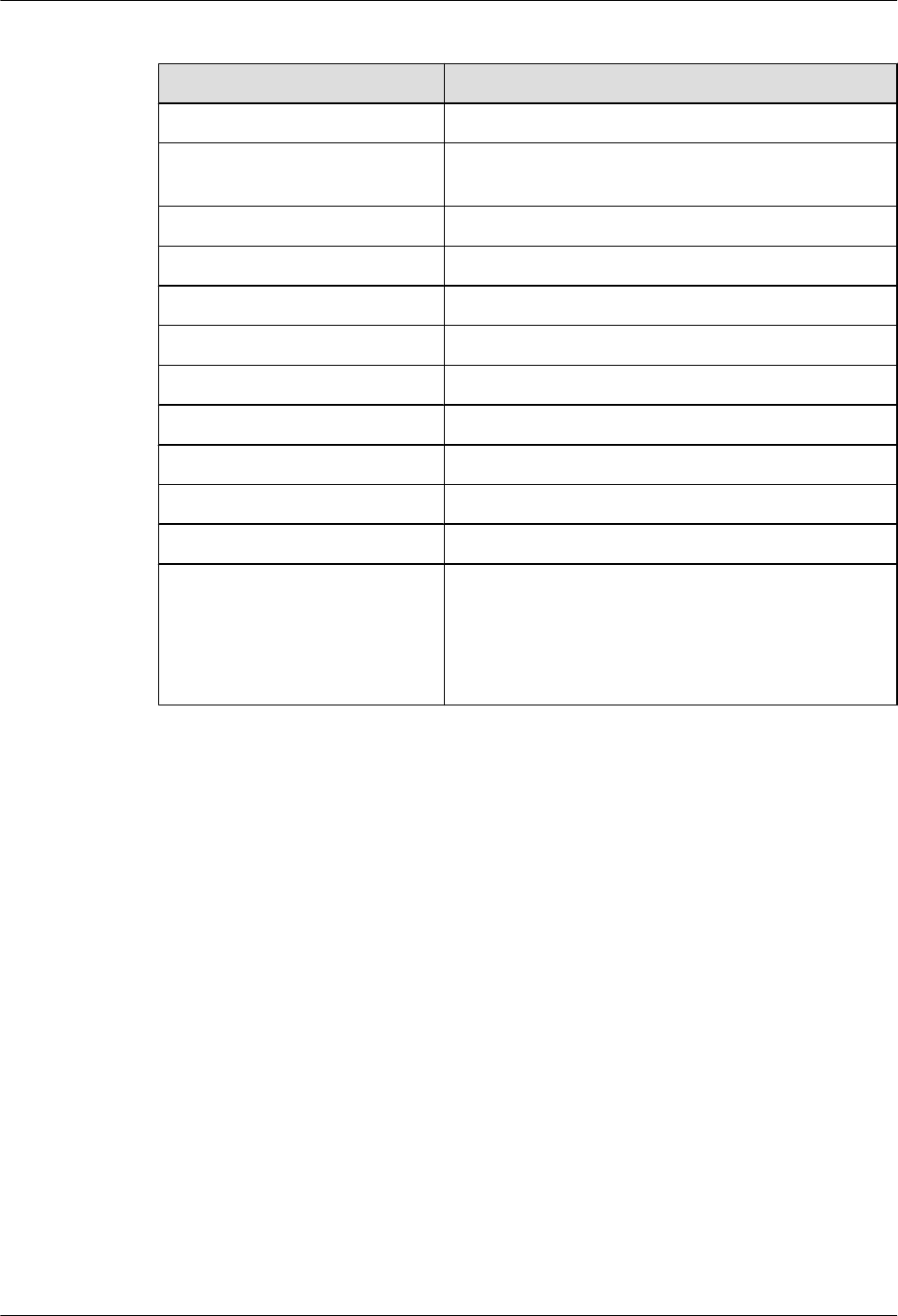
Table 6-8 Specifications of the network cable
Item Description
Connector type (X1/X2) RJ45 connectors
Cable type Category-3 and category-5 unshielded twisted pairs
(UTP-3 and UTP-5) or shielded twisted pairs (STP)
Color Dark gray
Characteristic impedance 100.0 Ω
Diameter 0.510 mm (0.02 in.)
Breakdown voltage 500.0 V
Impedance 93.8 Ω
Pin 8 pins
Frequency 0 MHz to 100 MHz
Frequency attenuation 22 dB/100 m@100 MHz
Fireproof level CM
Length lStraight through cable: 5 meters (16.4 ft.), 10 meters
(32.8 ft.), 20 meters (65.6 ft.), and 30 meters (98.5
ft.)
lCrossover cable: 5 meters (16.4 ft.) and 30 meters
(98.5 ft.)
6.6 Optical Fiber
An optical fiber connects the optical interface of a device to an upstream device or optical
network terminal.
Application
An optical fiber carries optical signals and transmits them over short distance. An optical fiber
connects the following:
lThe optical interface on a board
lThe optical distribution frame (ODF) or the optical interface on another device
Table 6-9 lists the classification of optical fibers.
Huawei AR1200-S&2200-S Series Enterprise Routers
Hardware Description 6 Cables
Issue 03 (2012-04-20) Huawei Proprietary and Confidential
Copyright © Huawei Technologies Co., Ltd.
105
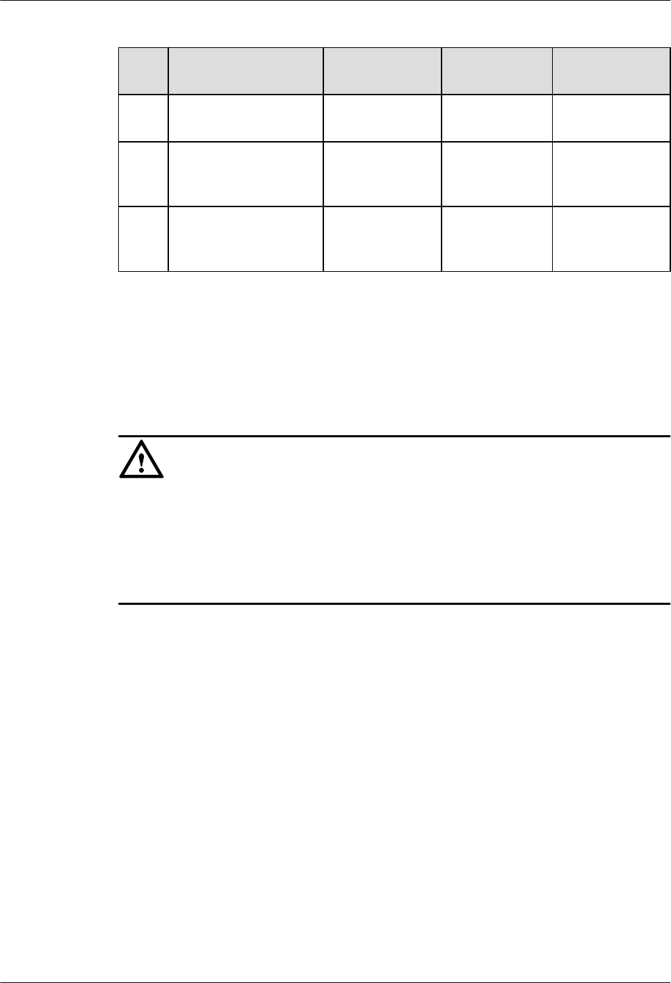
Table 6-9 Optical fiber classification
No. Purpose Local End
Connector
Remote End
Connector
Mode
1To connect LPU of the
device to the ODF
LC/PC FC/PC Single mode,
indoor
2 To connect LPUs of two
devices
LC/PC LC/PC Single mode/
multimode,
indoor
3 To connect LPU of the
device to another device
LC/PC SC/PC or LC/
PC
Single mode/
multimode,
indoor
Appearance
The appearances of the single-mode optical fiber and the multimode optical fiber are the same,
but their colors are different. The single-mode optical fiber is yellow, and the multi-mode optical
fiber is orange.
CAUTION
When connecting or removing the LC/PC optical connector, align the connector with the optical
interface, and do not rotate the fiber. Pay attention to the following points:
lAlign the head of the fiber jumper with the optical interface and insert the optical fiber into
the interface gently.
lTo remove the fiber, press the latch on the connector and pull the fiber out.
Figure 6-8 and Figure 6-9 show the appearances of the single mode fiber.
Huawei AR1200-S&2200-S Series Enterprise Routers
Hardware Description 6 Cables
Issue 03 (2012-04-20) Huawei Proprietary and Confidential
Copyright © Huawei Technologies Co., Ltd.
106
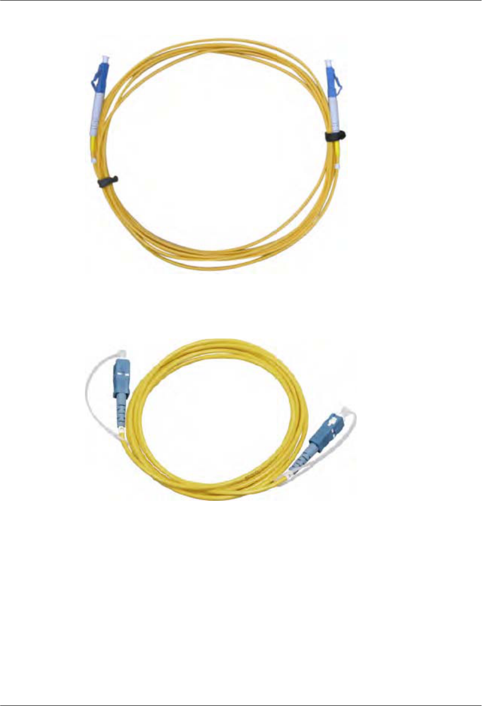
Figure 6-8 Single mode fiber with LC/PC connectors
Figure 6-9 Single mode fiber with SC/PC connectors
Figure 6-10 shows the appearance of the multimode fiber.
Huawei AR1200-S&2200-S Series Enterprise Routers
Hardware Description 6 Cables
Issue 03 (2012-04-20) Huawei Proprietary and Confidential
Copyright © Huawei Technologies Co., Ltd.
107
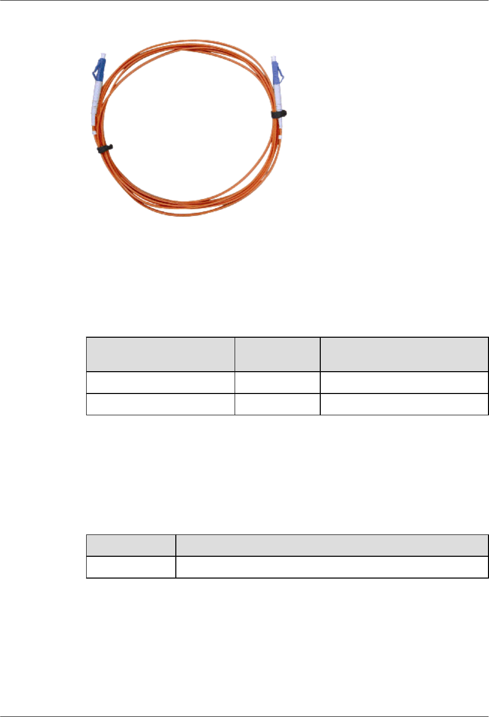
Figure 6-10 Multimode fiber with LC/PC connectors
Pin Assignments
Table 6-10 describes the pin assignments of the optical fiber.
Table 6-10 Pin assignments of the optical fiber
Local End Terminal Signal
Direction
Remote End Terminal
Optical interface Tx terminal -> Optical interface Rx terminal
Optical interface Rx terminal <- Optical interface Tx terminal
Fiber Selection Criterion
Table 6-11 lists the criteria for selecting optical fibers. Table 6-12 lists common optical
connectors.
Table 6-11 Fiber selection criterion
Parameter Criterion
Length Onsite survey result
Huawei AR1200-S&2200-S Series Enterprise Routers
Hardware Description 6 Cables
Issue 03 (2012-04-20) Huawei Proprietary and Confidential
Copyright © Huawei Technologies Co., Ltd.
108
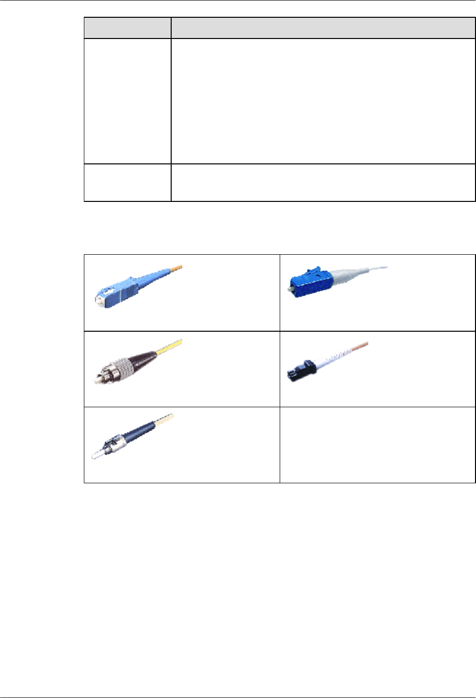
Parameter Criterion
Single mode or
multimode
Optical module type
lThe optical transmitting module of the multitransverse mode is
connected to the multimode fiber.
lThe optical transmitting module of the single-longitudinal mode or
multi-longitudinal mode is connected to the single mode fiber.
NOTE
If the optical fiber jumper is used, the connector connected to the device must be
the LC/PC connector, and the connector connected to the remote end must be of
the same type as the remote end interface.
Connector shape lCube: SC/PC, LC/PC, and MTRJ/PC
lColumn: ST/PC and FC/PC
Table 6-12 Common optical connectors
SC/PC optical connector
LC/PC optical connector
FC/PC optical connector MTRJ/PC optical connector
ST/PC optical connector
-
6.7 E1/T1 Trunk Cables
This section describes the structure and technical specifications of the E1/T1 trunk cable.
Introduction
E1 trunk cables are classified into 75-ohm unbalanced coaxial cables and 120-ohm balanced
twisted pair cables. The connectors of the cables are as follows:
l75-ohm unbalanced coaxial cable (DB9 to BNC):
–One end provides a DB9 connector.
–The other end provides two BNC connectors.
Huawei AR1200-S&2200-S Series Enterprise Routers
Hardware Description 6 Cables
Issue 03 (2012-04-20) Huawei Proprietary and Confidential
Copyright © Huawei Technologies Co., Ltd.
109
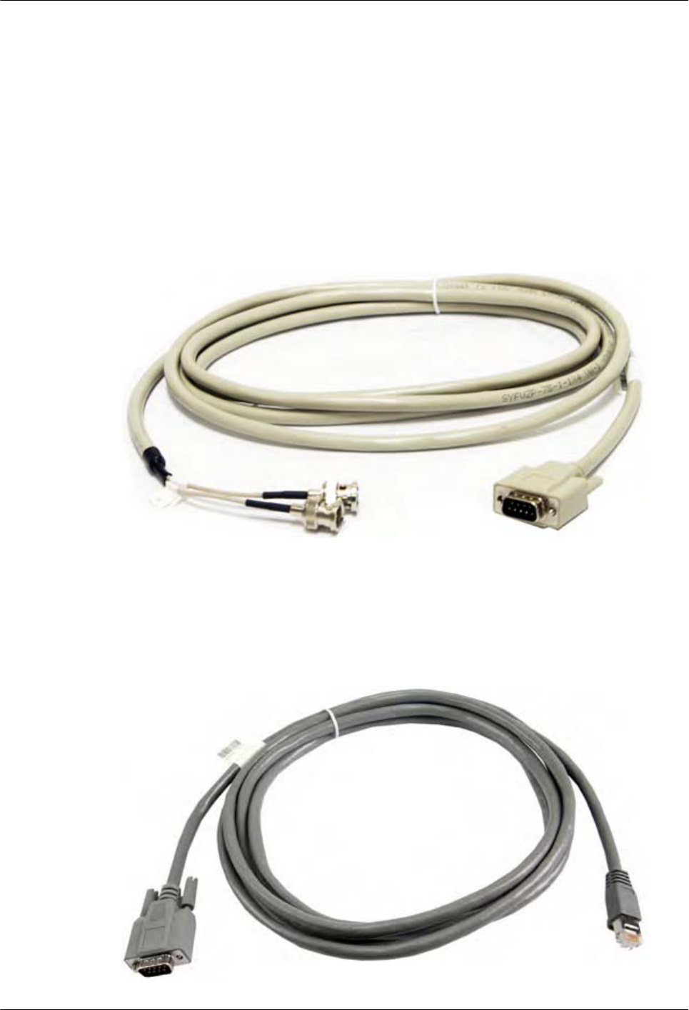
l120-ohm balanced twisted pair cable (DB9 to RJ45):
–One end provides a DB9 connector.
–The other end provides an RJ45 connector.
A T1 trunk cable is a 100-ohm balanced twisted pair cable. Its appearance is the same as the
appearance of an E1 120-ohm balanced twisted pair cable.
Appearance and Structure
Figure 6-11 shows the appearance of an E1 75-ohm unbalanced coaxial cable.
Figure 6-11 Appearance of an E1 75-ohm unbalanced coaxial cable
Figure 6-12 shows the appearance of the E1 120-ohm or T1 100-ohm balanced twisted pair
cable.
Figure 6-12 Appearance of the E1 120-ohm or T1 100-ohm balanced twisted pair cable
Huawei AR1200-S&2200-S Series Enterprise Routers
Hardware Description 6 Cables
Issue 03 (2012-04-20) Huawei Proprietary and Confidential
Copyright © Huawei Technologies Co., Ltd.
110
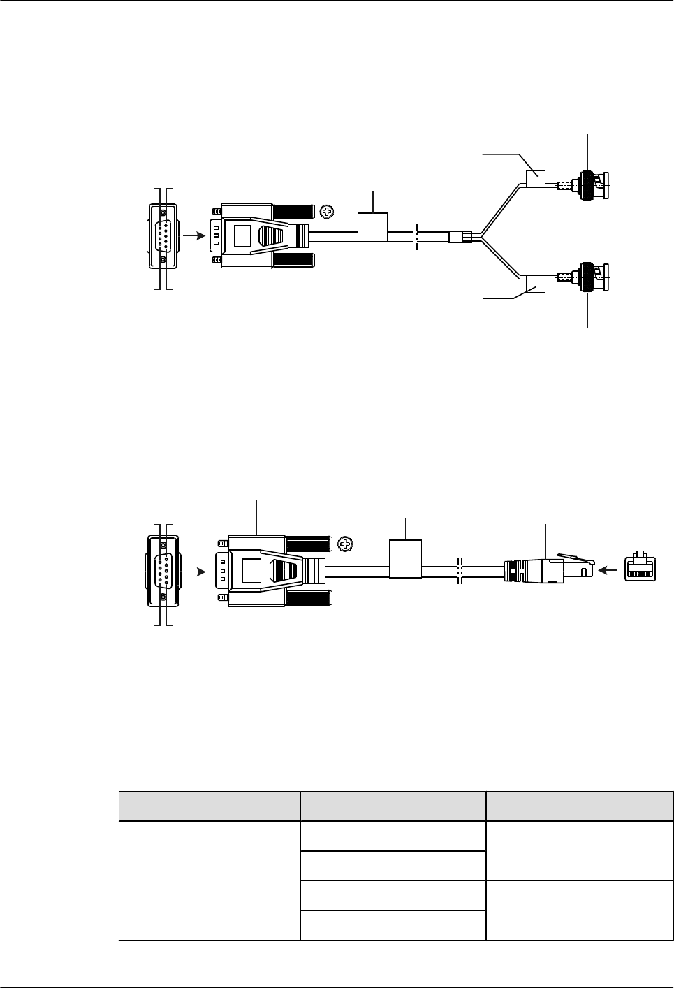
Figure 6-13 shows the structure of an E1 75-ohm unbalanced coaxial cable.
Figure 6-13 Structure of an E1 75-ohm unbalanced coaxial cable
Pos.5
Pos.6
Pos.9
Pos.1
X1
X2
X3
Main Label
BNC connector
D-type connector
(9-pin, male) Label 1
Label 2
BNC connector
Figure 6-14 shows the structure of the E1 120-ohm or T1 100-ohm balanced twisted pair cable.
Figure 6-14 Structure of the E1 120-ohm or T1 100-ohm balanced twisted pair cable
X1
X2
Pos.5
Pos.6
Pos.9
Pos.1
1 8
Label Network port connector
(8-pin, RJ-45)
D-type connector
(9-pin, male)
Pin Assignments
Table 6-13 describes the pin assignments of an E1 75-ohm unbalanced coaxial cable.
Table 6-13 Pin assignments of an E1 75-ohm unbalanced coaxial cable
Connector X1 (DB9) BNC Connector
Pin assignment 1X2
2
6 X3
7
Huawei AR1200-S&2200-S Series Enterprise Routers
Hardware Description 6 Cables
Issue 03 (2012-04-20) Huawei Proprietary and Confidential
Copyright © Huawei Technologies Co., Ltd.
111
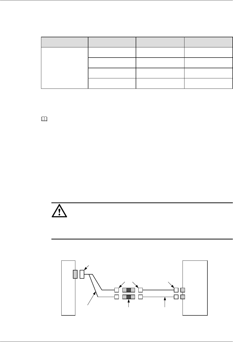
Table 6-14 describes the pin assignments of the E1 120-ohm or T1 100-ohm balanced twisted
pair cable.
Table 6-14 Pin assignments of the E1 120-ohm or T1 100-ohm balanced twisted pair cable
Connector X1 (DB9) X2 (RJ45) Tip Color
Pin assignment 1 4 White and orange
2 5 Orange
6 1 White and Blue
7 2 Blue
E1/T1 Trunk Cable Extension
NOTE
The E1/T1 trunk cable is 3 m long. If the connection distance is long, a cable extension is required.
lE1 75-ohm unbalanced coaxial cable: BNC to BNC (The two connectors are BNC 75 angle male-II.)
lE1 120-ohm or T1 100-ohm balanced twisted pair cable: RJ45 to RJ45 (The two connectors are RJ45.)
The E1 75-ohm unbalanced coaxial cable is connected as follows:
lIf the E1 trunk cable extension is not used, the BNC connector is connected to the remote
device.
lIf the E1 trunk cable extension is used, the BNC connector is connected to a coaxial
connector, and the coaxial connector is connected to the remote device through the cable
extension, as shown in Figure 6-15.
CAUTION
The Tx end of the E1 trunk cable is connected to the Rx end of the remote device, and the
Rx end is connected to the Tx end.
Figure 6-15 E1 75-ohm unbalanced coaxial cable extension
Router
DB9
connector
BNC
E1 75-ohm
unbalanced
coaxial cable
Coaxial
connector E1 75-ohm
cable extension
DDN
BNC
Huawei AR1200-S&2200-S Series Enterprise Routers
Hardware Description 6 Cables
Issue 03 (2012-04-20) Huawei Proprietary and Confidential
Copyright © Huawei Technologies Co., Ltd.
112
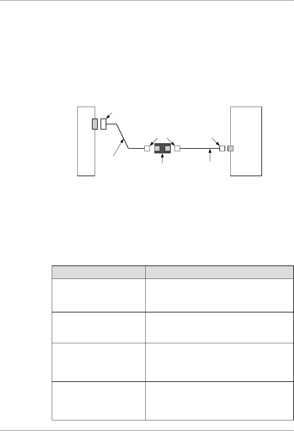
The E1 120-ohm or T1 100-ohm balanced twisted pair cable is connected as follows:
lIf the E1/T1 trunk cable extension is not used, the RJ45 connector is connected to the RJ45
interface of the remote device.
lIf the E1/T1 trunk cable extension is used, the RJ45 connector is connected to a network
interface connector, and the network interface connector is connected to the remote device
through the cable extension, as shown in Figure 6-16.
Figure 6-16 E1 120-ohm or T1 100-ohm balanced twisted pair cable extension
Router
DDN
DB9
connector
RJ45 RJ45
E1 120-ohm and
T1 100-ohm
balanced
twisted pair
Network
interface
connector
E1 120-ohm and
T1 100-ohm
cable extension
Specifications
Table 6-15 lists the specifications of the E1/T1 trunk cable.
Table 6-15 Specifications of the E1/T1 trunk cable
Item Description
Characteristic impedance lE1 75-ohm unbalanced coaxial cable: 75 ohm
lE1 120-ohm balanced twisted pair cable: 120 ohm
lT1 100-ohm balanced twisted pair cable: 100 ohm
Cable type lE1 75-ohm unbalanced coaxial cable: coaxial cable
lE1 120-ohm or T1 100-ohm balanced twisted pair
cable: balanced twisted pair cable
Color lE1 75-ohm unbalanced coaxial cable: PANTONE
WARM GREY 1U
lE1 120-ohm or T1 100-ohm balanced twisted pair
cable: PANTONE 430U
Diameter lE1 75-ohm unbalanced coaxial cable: 0.254 mm
(0.01 in.)
lE1 120-ohm or T1 100-ohm balanced twisted pair
cable: 0.4 mm (0.016 in.)
Huawei AR1200-S&2200-S Series Enterprise Routers
Hardware Description 6 Cables
Issue 03 (2012-04-20) Huawei Proprietary and Confidential
Copyright © Huawei Technologies Co., Ltd.
113
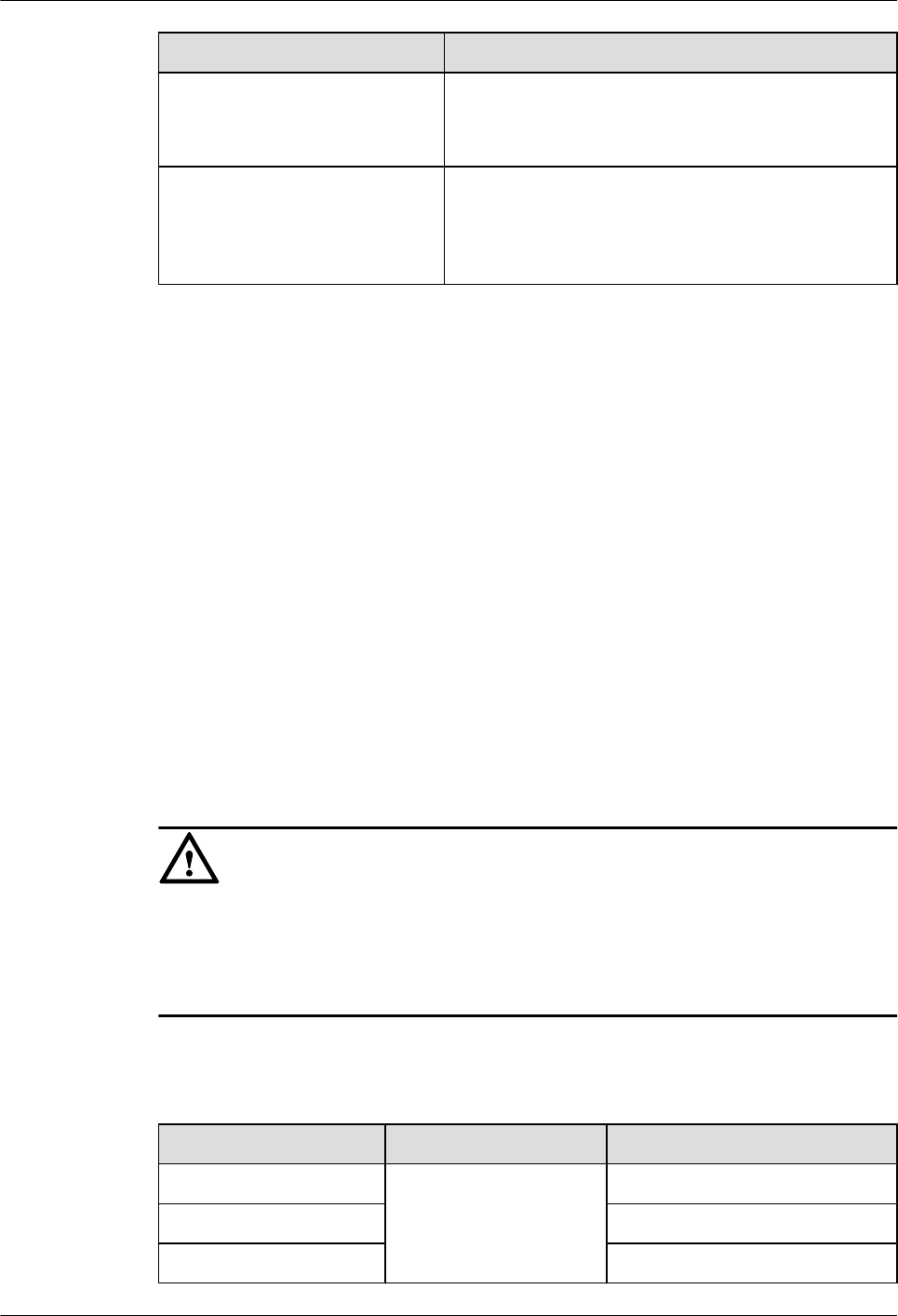
Item Description
Gauge lE1 75-ohm unbalanced coaxial cable: 30 AWG
lE1 120-ohm or T1 100-ohm balanced twisted pair
cable: 26 AWG
Cores lE1 75-ohm unbalanced coaxial cable:
SYFVZP-75-1-1*4
lE1 120-ohm or T1 100-ohm balanced twisted pair
cable: SEYVP-120
6.8 Synchronous/Asynchronous Serial Interface Cables
This section describes the categories, structure, and technical specifications of the synchronous/
asynchronous serial interface cable.
Introduction
A synchronous/asynchronous serial interface cable is connected as follows:
lThe DB28 connector is connected to the DB28 port on a card.
lAnother end depends on the connected device:
–If the wide area network (WAN) uses the DDN line, the cable is connected to the CSU/
DSU.
–If the WAN uses the dial-up line, the cable is connected to the modem.
Cable Category
CAUTION
Verify that devices are connected using appropriate synchronous/asynchronous serial interface
cables. Appropriate cable type is determined based on device connection mode (such as
synchronous/asynchronous and DTE/DCE modes), signals used by the connected device, baud
rate, and clock.
Table 6-16 lists the categories of synchronous/asynchronous serial interface cables.
Table 6-16 Categories of synchronous/asynchronous serial interface cables
Cable Local End Connector Network-side Connector
V.24 DTE cable DB28 connector DB25 (male) connector
V.24 DCE cable DB25 (female) connector
V.35 DTE cable DB28 (male) connector
Huawei AR1200-S&2200-S Series Enterprise Routers
Hardware Description 6 Cables
Issue 03 (2012-04-20) Huawei Proprietary and Confidential
Copyright © Huawei Technologies Co., Ltd.
114
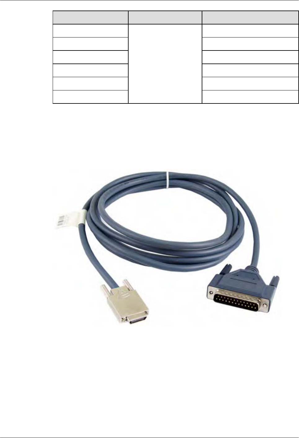
Cable Local End Connector Network-side Connector
V.35 DCE cable DB28 (female) connector
X.21 DTE cable DB15 (male) connector
RS449 DTE cable DB28 (male) connector
RS449 DCE cable DB28 (female) connector
RS530 DTE cable DB25 (male) connector
RS530 DCE cable DB25 (female) connector
Appearance
Figure 6-17 shows the appearance of the V.24 DTE cable.
Figure 6-17 Appearance of the V.24 DTE cable
Figure 6-18 shows the appearance of the V.24 DCE cable.
Huawei AR1200-S&2200-S Series Enterprise Routers
Hardware Description 6 Cables
Issue 03 (2012-04-20) Huawei Proprietary and Confidential
Copyright © Huawei Technologies Co., Ltd.
115
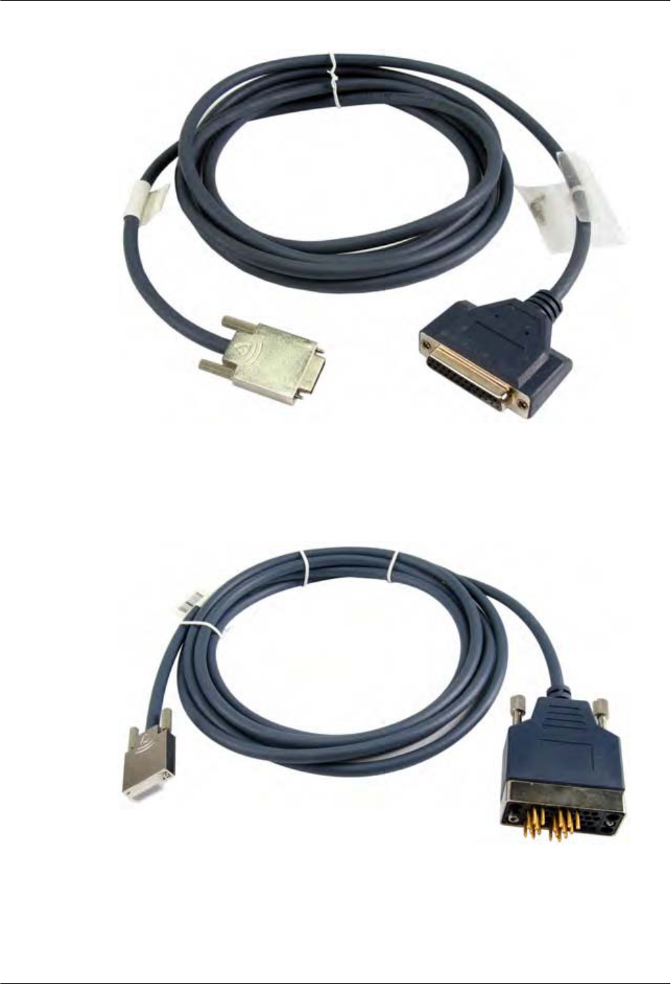
Figure 6-18 Appearance of the V.24 DCE cable
Figure 6-19 shows the appearance of the V.35 DTE cable.
Figure 6-19 Appearance of the V.35 DTE cable
Figure 6-20 shows the appearance of the V.35 DCE cable.
Huawei AR1200-S&2200-S Series Enterprise Routers
Hardware Description 6 Cables
Issue 03 (2012-04-20) Huawei Proprietary and Confidential
Copyright © Huawei Technologies Co., Ltd.
116
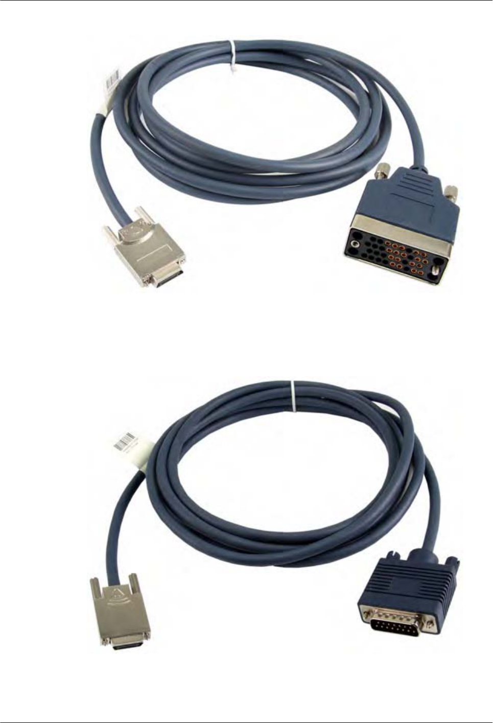
Figure 6-20 Appearance of the V.35 DCE cable
Figure 6-21 shows the appearance of the X.21 DTE cable.
Figure 6-21 Appearance of the X.21 DTE cable
Figure 6-22 shows the appearance of the RS449 DTE cable.
Huawei AR1200-S&2200-S Series Enterprise Routers
Hardware Description 6 Cables
Issue 03 (2012-04-20) Huawei Proprietary and Confidential
Copyright © Huawei Technologies Co., Ltd.
117
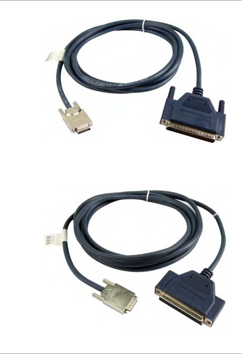
Figure 6-22 Appearance of the RS449 DTE cable
Figure 6-23 shows the appearance of the RS449 DCE cable.
Figure 6-23 Appearance of the RS449 DCE cable
Huawei AR1200-S&2200-S Series Enterprise Routers
Hardware Description 6 Cables
Issue 03 (2012-04-20) Huawei Proprietary and Confidential
Copyright © Huawei Technologies Co., Ltd.
118
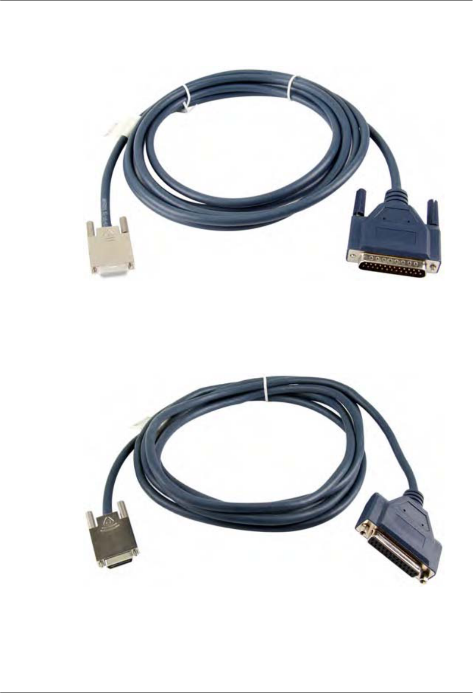
Figure 6-24 shows the appearance of the RS530 DTE cable.
Figure 6-24 Appearance of the RS530 DTE cable
Figure 6-25 shows the appearance of the RS530 DCE cable.
Figure 6-25 Appearance of the RS530 DCE cable
Specifications
Table 6-17 lists the specifications of the synchronous/asynchronous serial interface cable.
Huawei AR1200-S&2200-S Series Enterprise Routers
Hardware Description 6 Cables
Issue 03 (2012-04-20) Huawei Proprietary and Confidential
Copyright © Huawei Technologies Co., Ltd.
119
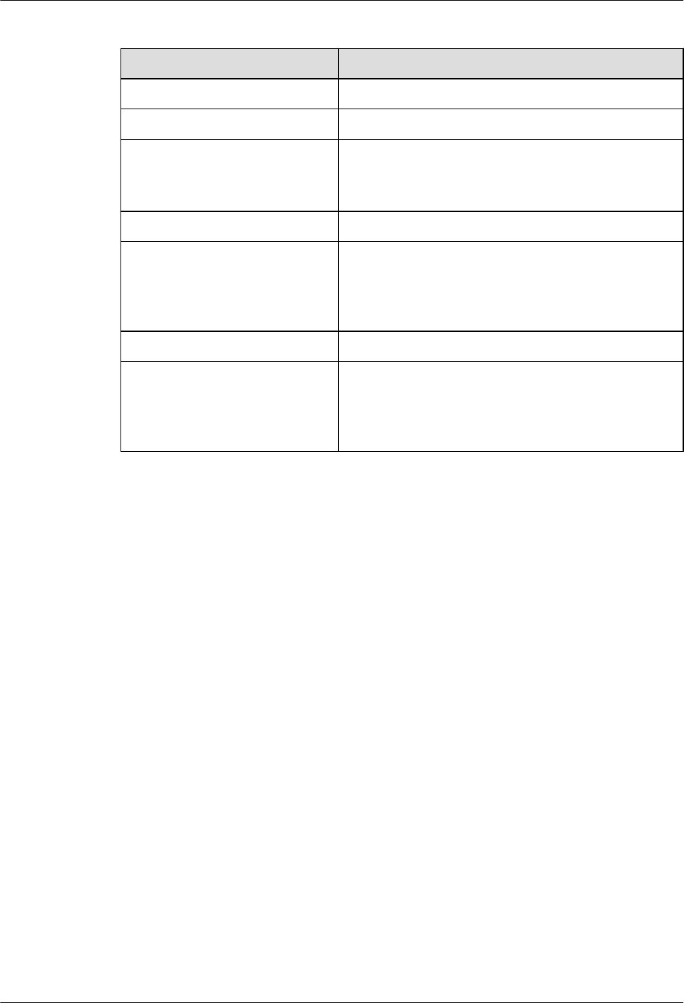
Table 6-17 Specifications of the synchronous/asynchronous serial interface cable
Item Description
Characteristic impedance 100 ohm
Cable type Twisted pair
Transmission rate lV.24: 1200 bit/s to 64 kbit/s
lV.35/X.21/RS449/RS530: 1200 bit/s to 2.048 Mbit/
s
Color Dark blue (PANTONE 296U)
Diameter lV.24 DTE/DCE cable, V.35 DTE/DCE cable, and X.
21 DTE cable: 0.38 mm (0.015 in.)
lRS449 DTE/DCE cable and RS530 DTE/DCE cable:
0.32 mm (0.013 in.)
Gauge 28 AWG
Pin lV.24 DTE/DCE cable, V.35 DTE/DCE cable, X.21
DTE cable: 5 pairs + 8 pins
lRS449 DTE/DCE cable and RS530 DTE/DCE cable:
26 pins
6.9 4G.SHDSL Cables
This section describes the structure and technical specifications of the 4G.SHDSL cable.
Introduction
The connectors of a 4G.SHDSL cable are as follows:
lFour RJ11 connectors on the local end
lAn RJ45 connector on the network side
Appearance and Structure
Figure 6-26 shows the appearance of the 4G.SHDSL cable.
Huawei AR1200-S&2200-S Series Enterprise Routers
Hardware Description 6 Cables
Issue 03 (2012-04-20) Huawei Proprietary and Confidential
Copyright © Huawei Technologies Co., Ltd.
120
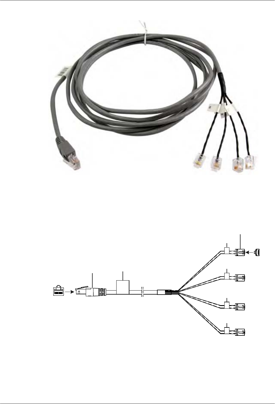
Figure 6-26 Appearance of the 4G.SHDSL cable
Figure 6-27 shows the structure of the 4G.SHDSL cable.
Figure 6-27 Structure of the 4G.SHDSL cable
X1
1 8
Main Label
X2
X3
X4
X5
1
6
Network port connector
(8-pin, RJ-45)
Label 1
Label 2
Label 3
Label 4
6-pin connector
Pin Assignments
Table 6-18 describes the pin assignments of the 4G.SHDSL cable.
Huawei AR1200-S&2200-S Series Enterprise Routers
Hardware Description 6 Cables
Issue 03 (2012-04-20) Huawei Proprietary and Confidential
Copyright © Huawei Technologies Co., Ltd.
121
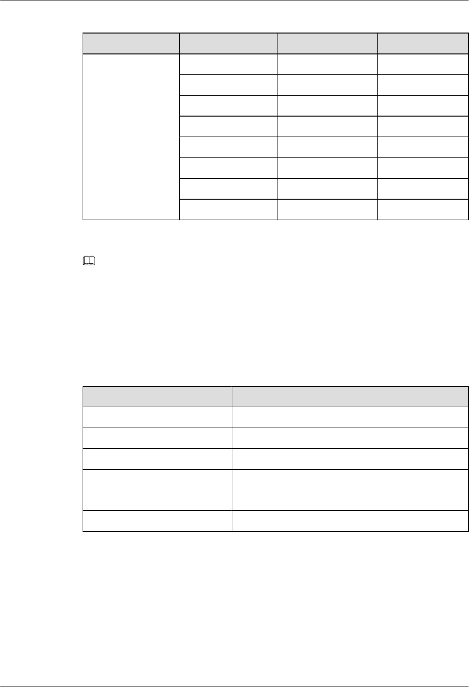
Table 6-18 Pin assignments of the 4G.SHDSL cable
Connector X1 (RJ45) X2/X3/X4/X5 (RJ11) Tip Color
Pin assignment 1 (LINE1 A) 2.3 White and orange
2 (LINE1 B) 2.4 Orange
3 (LINE2 A) 3.3 White and Green
6 (LINE2 B) 3.4 Green
4 (LINE0 A) 4.3 White and Blue
5 (LINE0 B) 4.4 Blue
7 (LINE3 A) 5.3 White and brown
8 (LINE3 B) 5.4 Brown
NOTE
As shown in Table 6-18, the 4G.SHDSL cable uses standard pin assignments. A cable has four ports, each
of them has two lines (A/B). The two lines in a port can be assigned in any sequence, but the line pairs
must be assigned in certain sequence.
Specifications
Table 6-19 lists the specifications of the 4G.SHDSL cable.
Table 6-19 Specifications of the 4G.SHDSL cable
Item Description
Characteristic impedance 100 ohm
Cable type Category 5 twisted pairs
Color PANTONE 430U
Diameter 0.51 mm (0.02 in.)
Gauge 24 AWG
Pin 8 pins
6.10 ISDN-ST Cables
This section describes the categories, structure, and technical specifications of the ISDN-ST
cable.
Introduction
ISDN-ST cables are classified into the following types:
Huawei AR1200-S&2200-S Series Enterprise Routers
Hardware Description 6 Cables
Issue 03 (2012-04-20) Huawei Proprietary and Confidential
Copyright © Huawei Technologies Co., Ltd.
122
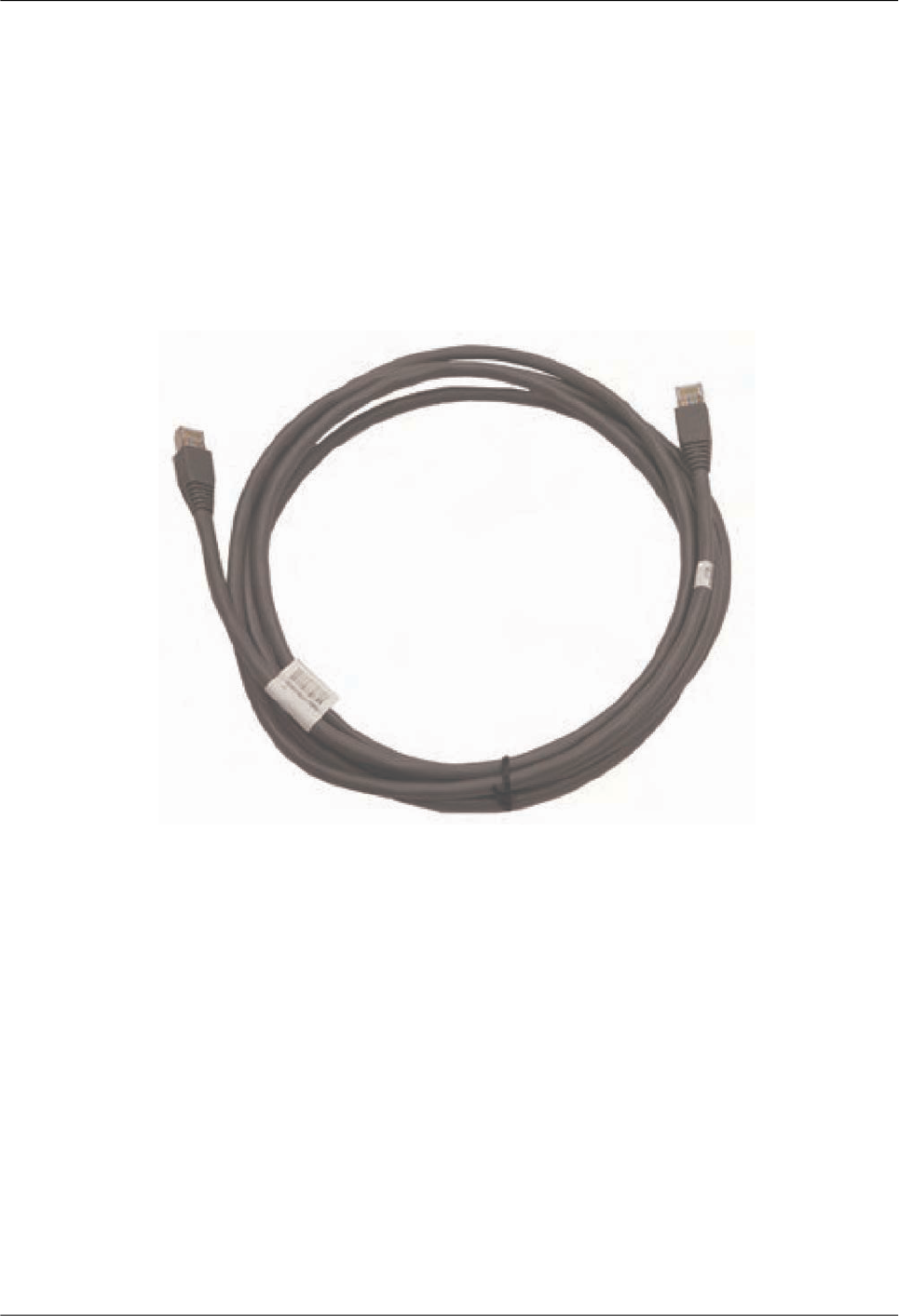
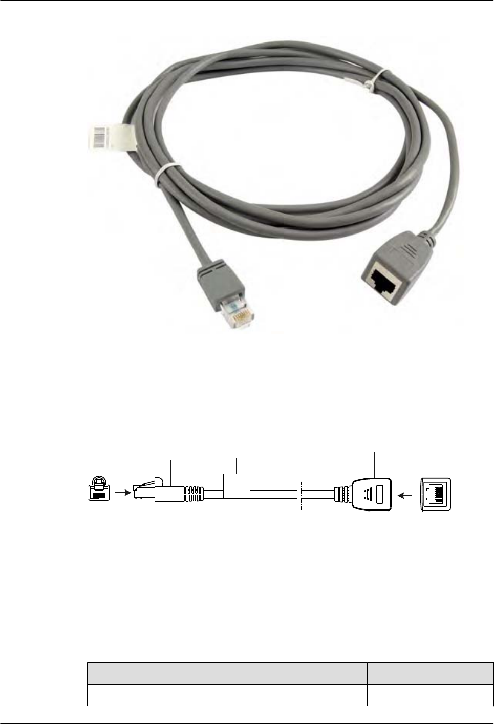
Figure 6-29 Appearance of an ISDN S/T interface crossover cable
Figure 6-30 shows the structure of an ISDN S/T interface crossover cable.
Figure 6-30 Structure of an ISDN S/T interface crossover cable
X1 X2
1
8
Label
Network port connector
(8-pin, RJ-45, male)
Network port connector
(8-pin, RJ-45, female)
1 8
Pin Assignments
Table 6-20 describes the pin assignments of the standard ISDN S/T interface cable. Pins 3 and
6 are the sending end, and pins 4 and 5 are the receiving end.
Table 6-20 Pin assignments of the standard ISDN S/T interface cable
RJ45 Signal RJ45
1 - 1
Huawei AR1200-S&2200-S Series Enterprise Routers
Hardware Description 6 Cables
Issue 03 (2012-04-20) Huawei Proprietary and Confidential
Copyright © Huawei Technologies Co., Ltd.
124
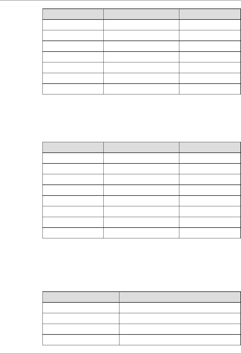
RJ45 Signal RJ45
2 - 2
3Tx+ 3
4 Rx+ 4
5 Rx- 5
6 Tx- 6
7 - 7
8 - 8
Table 6-21 describes the pin assignments of the ISDN S/T interface crossover cable. Pins 4 and
5 are the sending end, and pins 3 and 6 are the receiving end.
Table 6-21 Pin assignments of the standard ISDN S/T interface crossover cable
RJ45 (TE) Signal RJ45 (NT)
1 - 1
2 - 2
3Tx+ 4
4 Rx+ 3
5 Rx- 6
6 Tx- 5
7 - 7
8 - 8
Technical Specifications
Table 6-22 lists the technical specifications of an ISDN-ST cable.
Table 6-22 Technical specifications of an ISDN-ST cable
Item Specification
Characteristic impedance 100 ohm
Cable Category 5 twisted pairs
Color PANTONE 430U
Diameter 0.51 mm (0.02 in.)
Huawei AR1200-S&2200-S Series Enterprise Routers
Hardware Description 6 Cables
Issue 03 (2012-04-20) Huawei Proprietary and Confidential
Copyright © Huawei Technologies Co., Ltd.
125
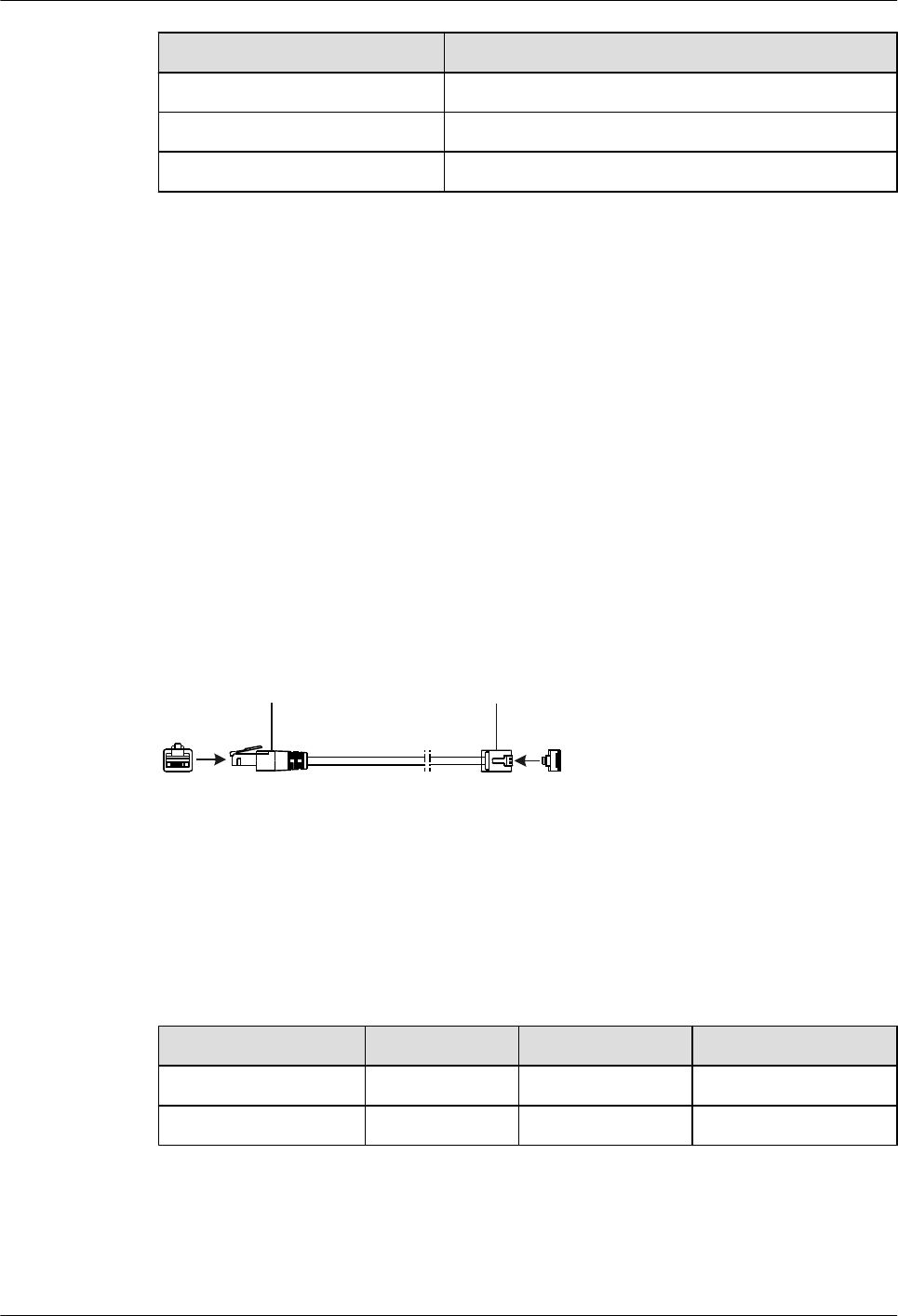
Item Specification
Gauge 24 AWG
Impedance 93.8 ohm
Pin 8 pins
6.11 Regular Telephone Lines
This section describes the structure and technical specifications of the regular telephone line.
Introduction
The regular telephone line is connected as follows:
lThe RJ11 connector is connected to a device such as a phone and fax machine.
lAnother RJ11 connector is connected to the voice card of the AR1200-S.
Appearance
Figure 6-31 shows the appearance of the regular telephone line.
Figure 6-31 Appearance of the regular telephone line
X1
1 6 X2
1
6
6PIN-RJ11 6PIN-RJ11
Pin Assignment
Table 6-23 provides the pin assignment of a regular telephone line.
Table 6-23 Pin assignment of a regular telephone line
X1 Pin Wire Color X2 Pin Remarks
3Red 3 Tip(+)
4 Green 4 Ring(-)
Specifications
Table 6-24 lists the specifications of the regular telephone line.
Huawei AR1200-S&2200-S Series Enterprise Routers
Hardware Description 6 Cables
Issue 03 (2012-04-20) Huawei Proprietary and Confidential
Copyright © Huawei Technologies Co., Ltd.
126

Table 6-24 Specifications of the regular telephone line
Item Description
Dielectric strength 150 V
Maximum current 1 A
Impedance 237.25 ohm
Cable type UL20251
Color White
Gauge 28 AWG
Pin 2 pins
6.12 8AS Cable
An 8AS cable is connected to an 8AS interface card to commission or maintain the 8AS interface
card.
Introduction
An 8AS cable connects the console port on an 8AS interface card to the serial port of an operation
terminal. You can use shield cables or unshielded cables as required in different scenarios.
The common usage scenarios of 8AS cables are:
lTo connect an 8AS interface card to automatic teller machines in a bank, use shield straight-
through cables. You can buy shield straight-through cables from Huawei or made these
cables onsite.
lTo connect an 8AS interface card to a dumb terminal, use a transit cable and a shield
straight-through cable. A transit cable has an RJ45 plug on one end and an RJ45 socket on
the other end. The transit cable converts the pin assignments on the dumb terminal to the
standard pin assignments, which are the same as those on the straight-through cable. Then
the straight-through cable can connect to the dumb terminal.
lTo connect an 8AS interface card to a serial port device, such as a PC or modem, use an
asynchronous serial cable and a transit cable. One end of an asynchronous serial cable is
an RJ45 socket, and the other end has a DB25 plug and a DB9 plug. The asynchronous
serial cable connects to the PC or modem through the transit cable.
NOTE
Huawei can customize 8AS cables of specified length.
Straight-through cable
Figure 6-32 shows the appearance of a straight-through cable.
Huawei AR1200-S&2200-S Series Enterprise Routers
Hardware Description 6 Cables
Issue 03 (2012-04-20) Huawei Proprietary and Confidential
Copyright © Huawei Technologies Co., Ltd.
127
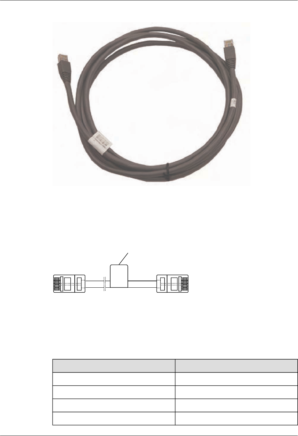

X1 Pin (8AS) X2 Pin (Console)
5 3
6 6
7 1
8 8
Table 6-8 lists the technical specifications of a straight-through cable.
Transit Cable
Figure 6-34 shows the appearance of a transit cable.
Figure 6-34 Transit cable appearance
Figure 6-35 shows the structure of a transit cable.
Huawei AR1200-S&2200-S Series Enterprise Routers
Hardware Description 6 Cables
Issue 03 (2012-04-20) Huawei Proprietary and Confidential
Copyright © Huawei Technologies Co., Ltd.
129
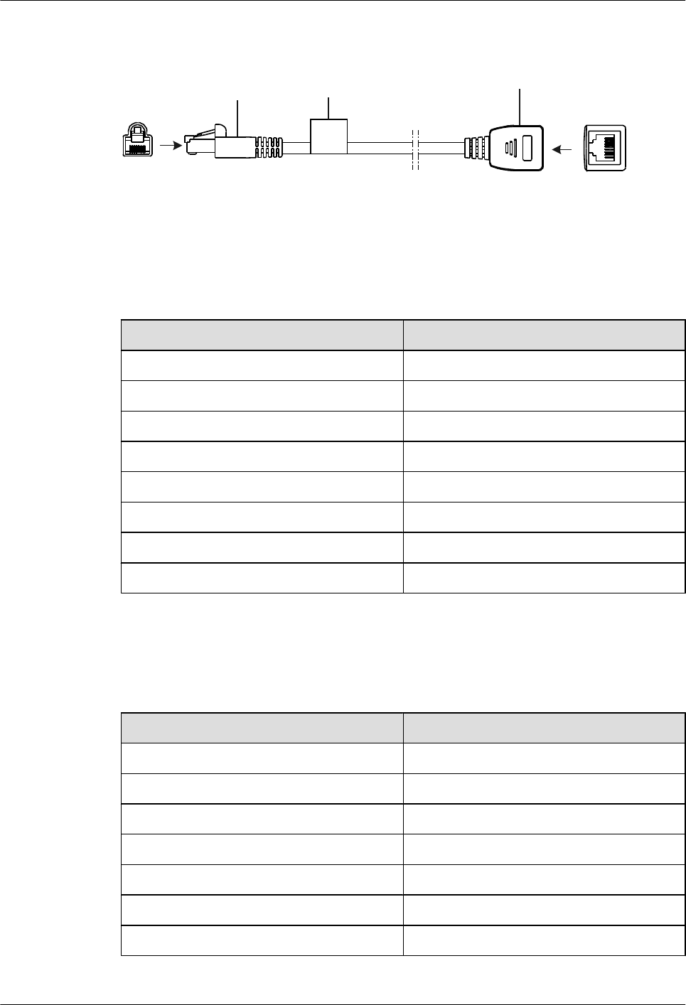
Figure 6-35 Transit cable structure
X1 X2
1
8
Label
Network port connector
(8-pin, RJ-45, male)
Network port connector
(8-pin, RJ-45, female)
1 8
Table 6-26 lists the pin assignments of a transit cable.
Table 6-26 Pin assignments of a transit cable
X1 X2
1 4
2 2
3 7
4 5
5 6
6 3
7 8
8 1
Table 6-27 lists the specifications of a transit cable.
Table 6-27 Specifications of a transit cable
Item Description
Characteristic impedance 100 ohm
Cable type Category 5 twisted pairs
Color PANTONE 430U
Core diameter of the inner conductor 0.51 mm
Wire gauge of the inner conductor 24 AWG
DC resistance of the inner conductor 93.8 ohm
Number of pins 8
Huawei AR1200-S&2200-S Series Enterprise Routers
Hardware Description 6 Cables
Issue 03 (2012-04-20) Huawei Proprietary and Confidential
Copyright © Huawei Technologies Co., Ltd.
130
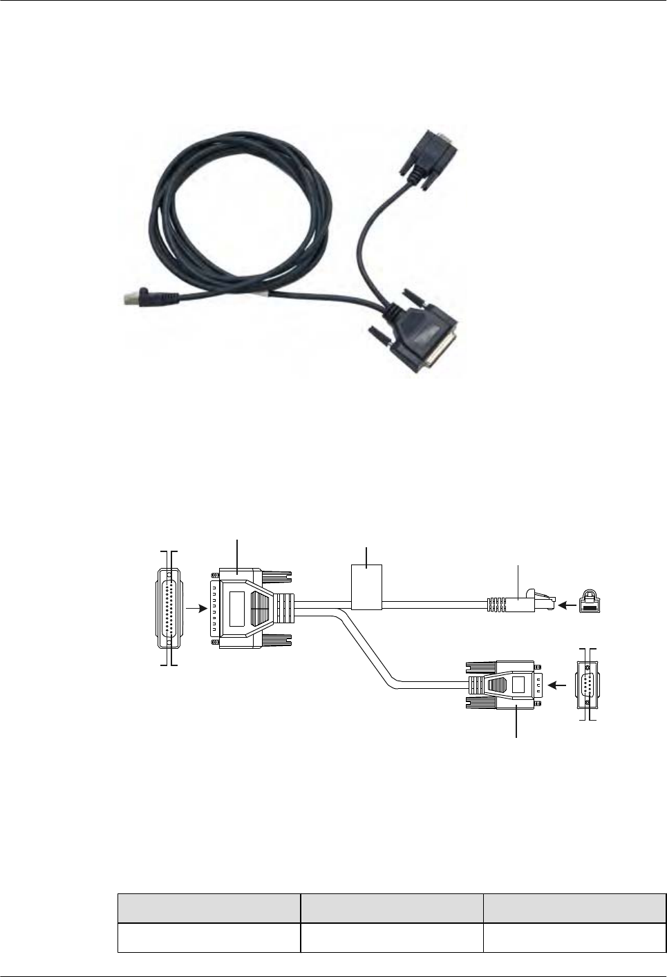
Asynchronous Serial Cable
Figure 6-36 shows the appearance of an asynchronous serial cable.
Figure 6-36 Appearance of an asynchronous serial cable
Figure 6-37 shows the structure of an asynchronous serial cable.
Figure 6-37 Structure of an asynchronous serial cable
Label
X1
X2
X3
D-type connector
(25-pin, male) Network port connector
(8-pin, RJ-45)
1 8
Pos.13
Pos.14
Pos.25
Pos.1
D-type connector
(9-pin, male)
Pos.5
Pos.6
Pos.9
Pos.1
Table 6-28 lists the pin assignments of an asynchronous serial cable.
Table 6-28 Pin assignments of an asynchronous serial cable
X1 X2 X3
417
Huawei AR1200-S&2200-S Series Enterprise Routers
Hardware Description 6 Cables
Issue 03 (2012-04-20) Huawei Proprietary and Confidential
Copyright © Huawei Technologies Co., Ltd.
131
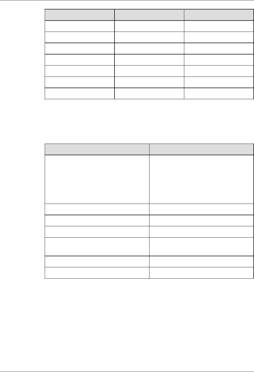
X1 X2 X3
20 2 4
233
841
755
362
676
588
Table 6-29 lists the specifications an asynchronous serial cable.
Table 6-29 Specifications of an asynchronous serial cable
Item Description
Connector lConnector X1: cable connector, D-type,
25-pin, male
lConnector X2: network interface
connector, RJ45, 8-pin, 8-bit
lConnector X3: cable connector, D-type,
9-pin, male
Cable type Symmetrical twisted pair
Color PANTONE WARM GRAY 1U
Core diameter of the inner conductor 0.32 mm
Wire gauge of the inner conductor 28 AWG (cross-sectional area approximately
equal to 0.08 mm2)
Number of pins 2 pairs
Length 3 m
6.13 3G Antenna
A 3G antenna transmits and receives 3G signals to enable an AR router to communicate with a
3G network.
Introduction
The antenna interfaces on a 3G-HSPA+7 interface card can connect to whip antennas and indoor
remote antennas.
Huawei AR1200-S&2200-S Series Enterprise Routers
Hardware Description 6 Cables
Issue 03 (2012-04-20) Huawei Proprietary and Confidential
Copyright © Huawei Technologies Co., Ltd.
132

lWhip antennas are directly installed on an AR router and are recommended when a router
is desk installed or wall mounted.
lIndoor remote antennas have a 3 m long feed line and can use two 6 m feed lines to expand
the length to 15 m. Indoor remote antennas are recommended when an AR router is installed
in a cabinet or rack. (Indoor remote antennas need to be ordered separately if needed.)
Whip Antenna
Figure 6-38 shows the appearance of a whip antenna.
Figure 6-38 Whip antenna
Table 6-30 lists the technical specifications of a whip antenna.
Table 6-30 Technical specifications of a whip antenna
Item Description
Connector SMA-J
Color Black
Characteristic impedance 50 ohm
Length 150 mm
Frequency 824 MHz to 960 MHz/1710 MHz to 2170
MHz
Maximum power 10 W
Operating temperature -40°C to +70°C
Huawei AR1200-S&2200-S Series Enterprise Routers
Hardware Description 6 Cables
Issue 03 (2012-04-20) Huawei Proprietary and Confidential
Copyright © Huawei Technologies Co., Ltd.
133

Item Description
Relative humidity 5% RH to 90% RH, non-condensing
Gain l824 MHz to 960 MHz: 1d Bi
l1710 MHz to 2170 MHz: 2 dBi
Voltage standing wave ratio < 3
Remote Antenna
Figure 6-39 shows the appearance of a remote antenna.
Figure 6-39 Remote antenna
Table 6-31 lists the technical specifications of a remote antenna.
Huawei AR1200-S&2200-S Series Enterprise Routers
Hardware Description 6 Cables
Issue 03 (2012-04-20) Huawei Proprietary and Confidential
Copyright © Huawei Technologies Co., Ltd.
134
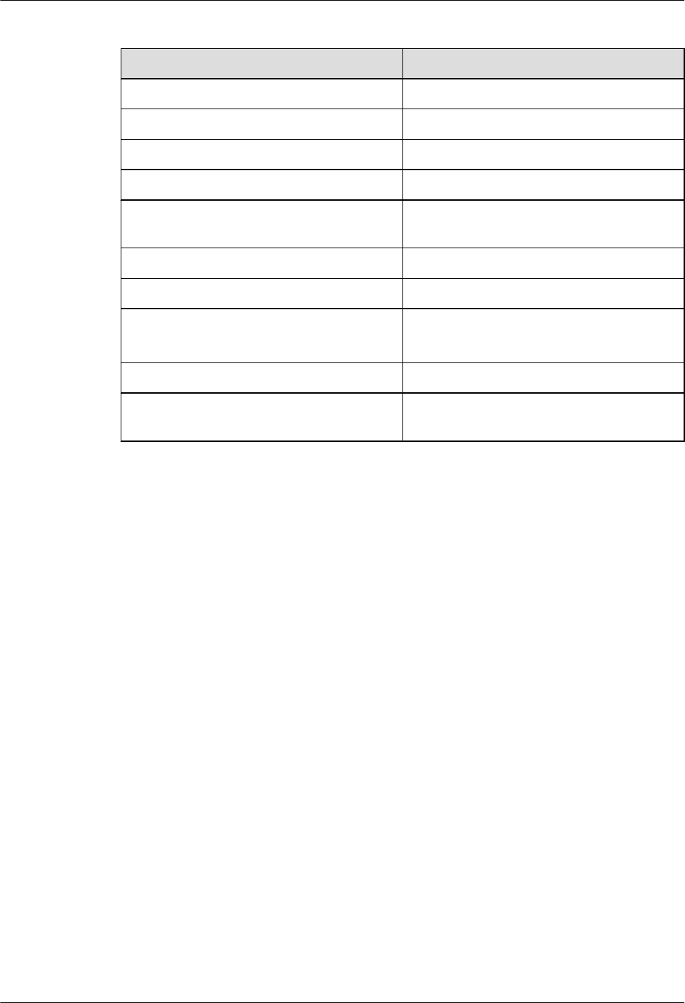
Table 6-31 Technical specifications of a remote antenna
Item Description
Connector SMA-Male
Color Black
Characteristic impedance 50 ohm
Height 260 mm
Frequency 824 MHz to 960 MHz/1710 MHz to 2170
MHz
Maximum power 50 W
Operating temperature -40°C to +90°C
Gain l824 MHz to 960 MHz: 1 dBi
l1710 MHz to 2170 MHz: 2.5 dBi
Voltage standing wave ratio < 2.5
Attenuation < 0.3 dB on each meter of feed line (within
the working frequency band)
Huawei AR1200-S&2200-S Series Enterprise Routers
Hardware Description 6 Cables
Issue 03 (2012-04-20) Huawei Proprietary and Confidential
Copyright © Huawei Technologies Co., Ltd.
135

7 List of Indicators
About This Chapter
This chapter describes the status and meanings of indicators on the AR routers, including
indicators on the front and rear panels, cards, fan modules, and power supply units.
7.1 Indicators on the AR1200-S Panel
This section describes the indicators on the AR1200-S panel.
7.2 Indicators on the AR2220-S Panel
This section describes the indicators on the AR2220-S panel.
7.3 Power Indicators
This section describes the power indicators.
Huawei AR1200-S&2200-S Series Enterprise Routers
Hardware Description 7 List of Indicators
Issue 03 (2012-04-20) Huawei Proprietary and Confidential
Copyright © Huawei Technologies Co., Ltd.
136
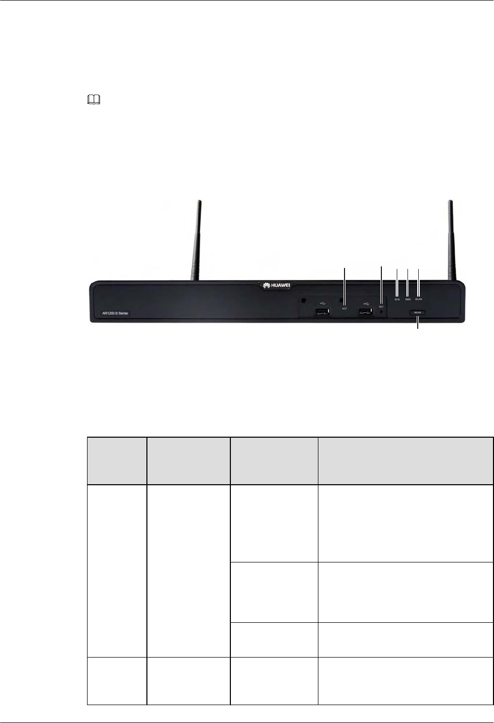
7.1 Indicators on the AR1200-S Panel
This section describes the indicators on the AR1200-S panel.
NOTE
The indicators on the AR1220W-S and AR1220-S front panels are the same. The AR1220W-S is used as
an example to describe the indicators.
Figure 7-1 shows the indicators on the AR1220W-S front panel.
Figure 7-1 Indicators on the AR1220W-S front panel
3 4 1 2 5
6
Table 7-1 describes the indicators on the AR1220W-S front panel.
Table 7-1 Indicators on the AR1220W-S front panel
Number
in Figure
7-1
Indicator Color Description
1SYS Green If the indicator blinks once 2s (0.5 Hz),
the system is running properly.
If the indicator blinks once 0.25s (4
Hz), the system is powering on or
restarting.
Red If the indicator is red, a fault that affects
services occurs and cannot be rectified
automatically. The fault needs to be
rectified manually.
Off If the indicator is off, the software is
not running or is being reset.
2 WAN Green If the indicator is steady on, at least one
GE interface has been connected or
activated.
Huawei AR1200-S&2200-S Series Enterprise Routers
Hardware Description 7 List of Indicators
Issue 03 (2012-04-20) Huawei Proprietary and Confidential
Copyright © Huawei Technologies Co., Ltd.
137

Number
in Figure
7-1
Indicator Color Description
If the indicator is off, neither GE
interface is connected or activated.
3 ACT Red and green If the indicator is green, devices have
been deployed by using the USB disk.
If the indicator blinks green, data is
being read from the USB disk.
If the indicator is red, the device cannot
be correctly connected to the NMS or
cannot be registered with the NMS.
If the indicator blinks red, an error
occurs when configuration files are
being executed or data is being read
from the USB disk.
If the indicator is off, the USB disk is
not inserted, the USB interface fails, or
the indicator fails.
4 RST CAUTION
The Reset button is used for resetting the device manually.
Resetting the device will cause service interruption; therefore,
confirm the action before you reset the device.
5 WLAN Green If the indicator is steady on, the link has
been connected or activated.
If the indicator blinks (≤20 Hz), the
link is transmitting data. If the traffic
volume of transmitted data increases,
the indicator blinks faster.
If the indicator is off, the link is not
connected or activated.
6 WLAN The button enables and disables the WLAN function.
Figure 7-2 shows the indicators on the AR1220W-S rear panel.
Huawei AR1200-S&2200-S Series Enterprise Routers
Hardware Description 7 List of Indicators
Issue 03 (2012-04-20) Huawei Proprietary and Confidential
Copyright © Huawei Technologies Co., Ltd.
138
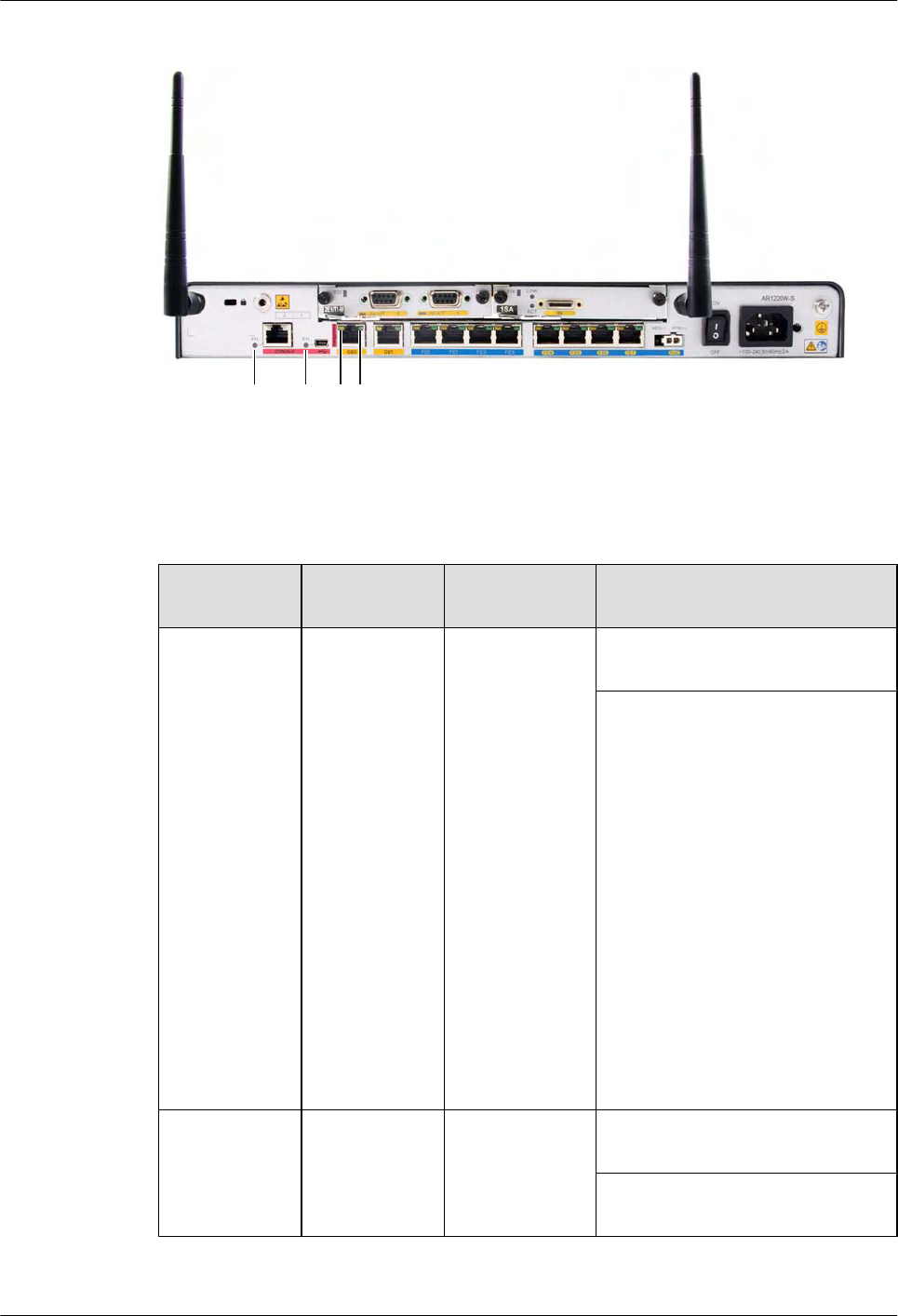
Figure 7-2 Indicators on the AR1220W-S rear panel
7 8 9 10
Table 7-2 shows the indicators on the AR1220W-S rear panel.
Table 7-2 Description of indicators on the AR1220W-S rear panel
Number in
Figure 7-2
Indicator Color Description
7EN (CON/
AUX interface)
NOTE
lEither the
CON/AUX
port or the
MiniUSB
port can be
used at a
time.
lBy default,
the port is
used as the
CON/AUX
port. The
EN
indicator is
green no
matter
whether a
cable is
installed.
Green If the indicator is steady on, the port
is used as a CON/AUX port.
If the indicator is off, the port does
not function as a CON/AUX port.
8 EN (MiniUSB
interface)
Green If the indicator is steady on, the port
is used as a MiniUSB port.
If the indicator is off, the port does
not function as a MiniUSB port.
Huawei AR1200-S&2200-S Series Enterprise Routers
Hardware Description 7 List of Indicators
Issue 03 (2012-04-20) Huawei Proprietary and Confidential
Copyright © Huawei Technologies Co., Ltd.
139
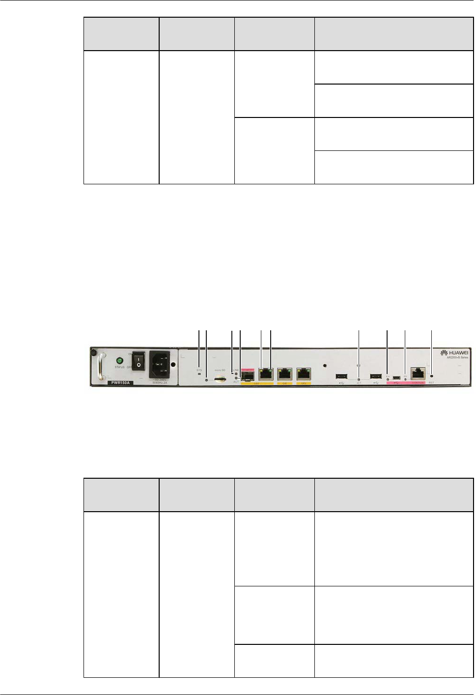
Number in
Figure 7-2
Indicator Color Description
9 and 10 GE interface
indicators:
lThe LINK
indicator is
in green.
lThe ACT
indicator is
in yellow.
Green If the indicator is steady on, a link
has been established.
If the indicator is off, no link is
established.
Yellow If the indicator is blinking, data is
being transmitted or received.
If the indicator is off, no data is being
transmitted or received.
7.2 Indicators on the AR2220-S Panel
This section describes the indicators on the AR2220-S panel.
Figure 7-3 shows the indicators on the AR2220-S front panel.
Figure 7-3 Indicators on the AR2220-S front panel
1 2 34 5 6 7 8 9 10
Table 7-3 describes the indicators on the AR2220-S front panel.
Table 7-3 Indicators on the AR2220-S front panel
Number in
Figure 7-3
Indicator Color Description
1SYS Green If the indicator blinks once 2s (0.5
Hz), the system is running properly.
If the indicator blinks once 0.25s (4
Hz), the system is powering on or
restarting.
Red If the indicator is red, a fault that
affects services occurs and cannot be
rectified automatically. The fault
needs to be rectified manually.
Off If the indicator is off, the software is
not running or is being reset.
Huawei AR1200-S&2200-S Series Enterprise Routers
Hardware Description 7 List of Indicators
Issue 03 (2012-04-20) Huawei Proprietary and Confidential
Copyright © Huawei Technologies Co., Ltd.
140
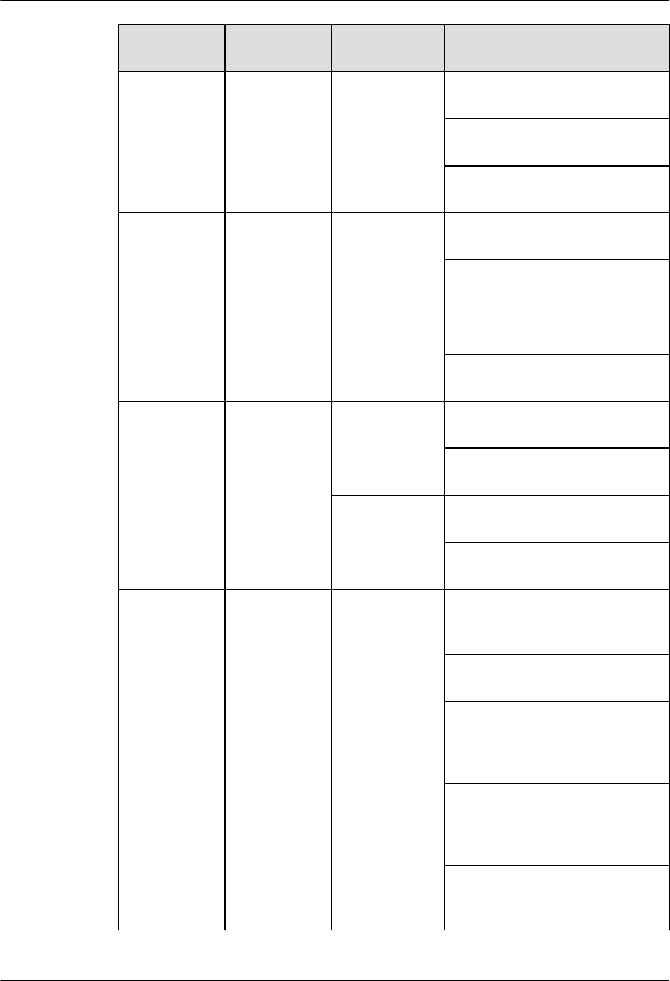
Number in
Figure 7-3
Indicator Color Description
2MiniSD card
indicator
Green If the indicator is steady on, a link
has been established.
If the indicator is blinking, data is
being transmitted or received.
If the indicator is off, there is no
MiniSD card.
3 and 4 SFP interface
indicators:
lThe LINK
indicator is
in green.
lThe ACT
indicator is
in yellow.
Green If the indicator is steady on, a link
has been established.
If the indicator is off, no link is
established.
Yellow If the indicator is blinking, data is
being transmitted or received.
If the indicator is off, no data is being
transmitted or received.
5 and 6 GE interface
indicators:
lThe LINK
indicator is
in green.
lThe ACT
indicator is
in yellow.
Green If the indicator is steady on, a link
has been established.
If the indicator is off, no link is
established.
Yellow If the indicator is blinking, data is
being transmitted or received.
If the indicator is off, no data is being
transmitted or received.
7 ACT Red and green If the indicator is green, devices have
been deployed by using the USB
disk.
If the indicator blinks green, data is
being read from the USB disk.
If the indicator is red, the device
cannot be correctly connected to the
NMS or cannot be registered with
the NMS.
If the indicator blinks red, an error
occurs when configuration files are
being executed or data is being read
from the USB disk.
If the indicator is off, the USB disk
is not inserted, the USB interface
fails, or the indicator fails.
Huawei AR1200-S&2200-S Series Enterprise Routers
Hardware Description 7 List of Indicators
Issue 03 (2012-04-20) Huawei Proprietary and Confidential
Copyright © Huawei Technologies Co., Ltd.
141

Number in
Figure 7-3
Indicator Color Description
8EN (MiniUSB
interface)
Green If the indicator is steady on, the port
is used as a MiniUSB port.
If the indicator is off, the port does
not function as a MiniUSB port.
9 EN (CON/
AUX interface)
NOTE
lEither the
CON/AUX
port or the
MiniUSB
port can be
used at a
time.
lBy default,
the port is
used as the
CON/AUX
port. The
EN
indicator is
green no
matter
whether a
cable is
installed.
Green If the indicator is steady on, the port
is used as a CON/AUX port.
If the indicator is off, the port does
not function as a CON/AUX port.
10 RST CAUTION
The Reset button is used for resetting the device manually.
Resetting the device will cause service interruption; therefore,
confirm the action before you reset the device.
7.3 Power Indicators
This section describes the power indicators.
HW-100-48AC14D
Figure 7-4 shows the indicator of the HW-100-48AC14D.
Huawei AR1200-S&2200-S Series Enterprise Routers
Hardware Description 7 List of Indicators
Issue 03 (2012-04-20) Huawei Proprietary and Confidential
Copyright © Huawei Technologies Co., Ltd.
142
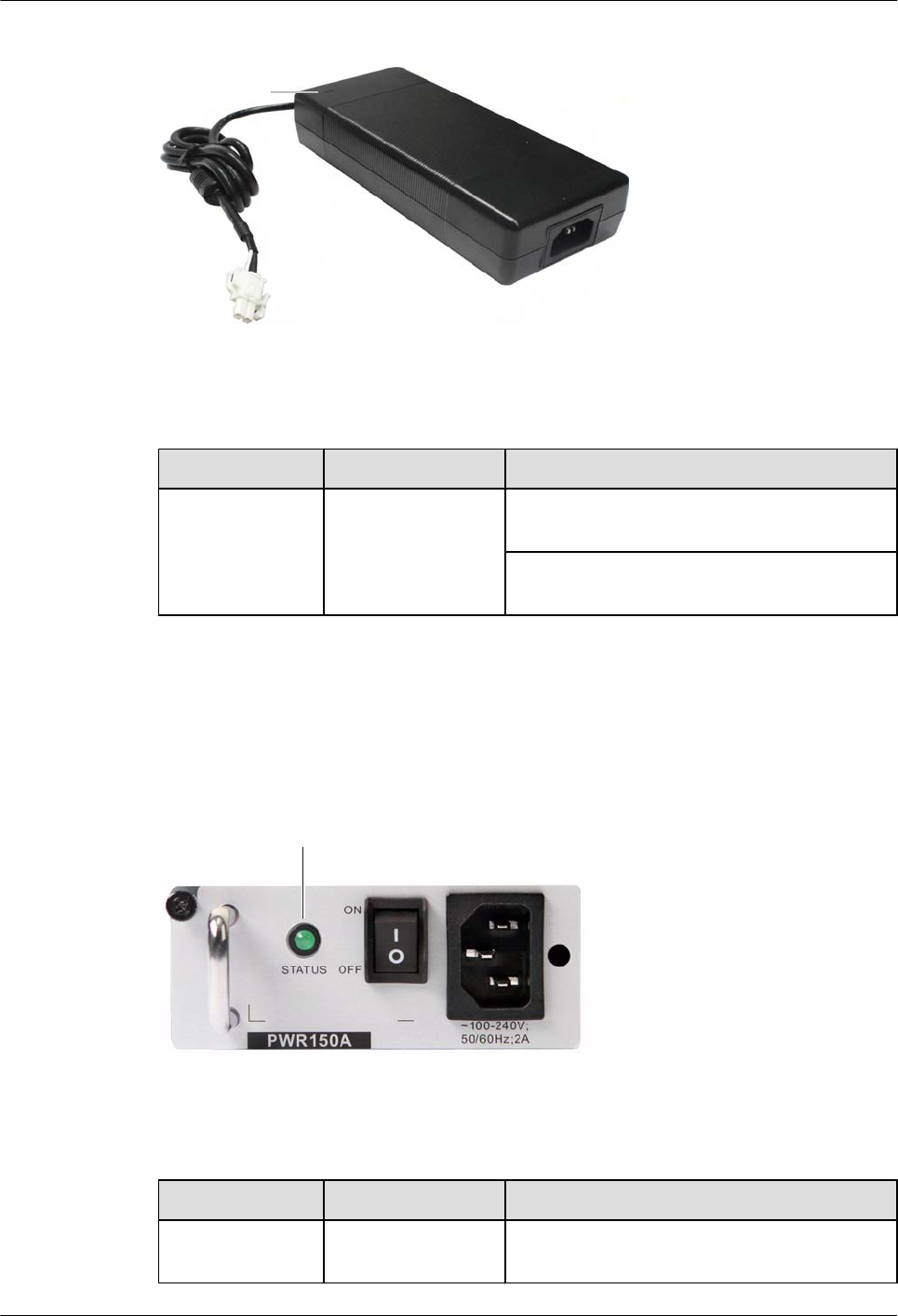
Figure 7-4 Indicator of the HW-100-48AC14D
In dicator
Table 7-4 Description of the HW-100-48AC14D indicators
Indicator Color Description
Power indicator Blue If the indicator is steady on, the output power is
in the normal range.
If the indicator is off, the power supply unit does
not have output power.
PWR150A
Figure 7-5 shows the indicator of the PWR150A.
Figure 7-5 Indicator of the PWR150A
Indicator
Table 7-5 Description of the PWR150A indicators
Indicator Color Description
Power indicator
(STATUS)
Green If the indicator is steady on, the power supply
unit functions properly.
Huawei AR1200-S&2200-S Series Enterprise Routers
Hardware Description 7 List of Indicators
Issue 03 (2012-04-20) Huawei Proprietary and Confidential
Copyright © Huawei Technologies Co., Ltd.
143

Indicator Color Description
If the indicator blinks, the output power is out of
range, for example, overvoltage, overcurrent,
and short-circuit.
If the indicator is off, the input power is out of
range, for example no AC input, overvoltage,
and undervoltage, or the output power is out of
range, for example, undervoltage and
overtemperature.
Huawei AR1200-S&2200-S Series Enterprise Routers
Hardware Description 7 List of Indicators
Issue 03 (2012-04-20) Huawei Proprietary and Confidential
Copyright © Huawei Technologies Co., Ltd.
144

8 List of Cards
About This Chapter
This chapter describes the types and technical specifications of cards on the AR routers.
8.1 Cards Supported by the AR
This section describes the cards supported by AR routers, including SRUs, Ethernet LAN
interface cards, WAN interface cards, voice interface cards, and xDSL/xPON interface cards.
8.2 Power Consumption and Weight
This section describes the power consumption and weight of cards supported by the AR routers.
Huawei AR1200-S&2200-S Series Enterprise Routers
Hardware Description 8 List of Cards
Issue 03 (2012-04-20) Huawei Proprietary and Confidential
Copyright © Huawei Technologies Co., Ltd.
145
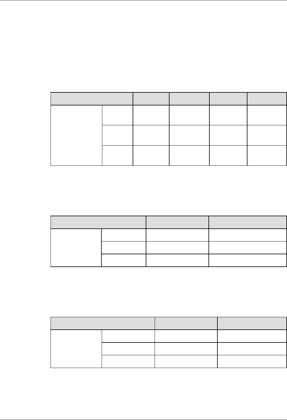
8.1 Cards Supported by the AR
This section describes the cards supported by AR routers, including SRUs, Ethernet LAN
interface cards, WAN interface cards, voice interface cards, and xDSL/xPON interface cards.
Matching between physical cards and software versions
Table 8-1 Matching between physical cards and software versions
Model&Version SIC WSIC XSIC voice card
ARV200R001C0
1&ARV200R002
C00&ARV200R0
02C01
AR1220-
S
√ √ × ×
AR1220
W-S
√ √ × ×
AR2220-
S
√ √ √ √
Matching between SRUs and software versions
Table 8-2 Matching between SRUs and software versions
Model&Version SRU WLAN Subcard
ARV200R001C0
1&ARV200R002
C00&ARV200R
002C01
AR1220-S × ×
AR1220W-S × √
AR2220-S × ×
Matching between Ethernet LAN interface cards and software versions
Table 8-3 Matching between Ethernet LAN interface cards and software versions
Model&Version 8FE1GE 24GE
ARV200R001C0
1&ARV200R002
C00&ARV200R
002C01
AR1220-S √ ×
AR1220W-S √ ×
AR2220-S √ √
Huawei AR1200-S&2200-S Series Enterprise Routers
Hardware Description 8 List of Cards
Issue 03 (2012-04-20) Huawei Proprietary and Confidential
Copyright © Huawei Technologies Co., Ltd.
146

Matching between WAN cards and software versions
Table 8-4 Matching between WAN cards and software versions
Model&Ver
sion
2F
E
1E1
T1-
M/
2E1
T1-
M
(SIC
)
2E1
T1-
M
(WS
IC)
1E
1T
1-
F/
2E
1T
1-F
1S
A
2S
A
1
G
E
C
8
A
S
1
B
S
T
1
C
P
O
S-
15
5
M
3
G
-
H
S
P
A
+
7
4
G
E
W
-T
4
G
E
W
-S
ARV
200R
001C
01
AR1
220-
S
√ √ × √ √ √ √ √ √ × × × ×
AR1
220
W-S
√ √ × √ √ √ √ √ √ × × × ×
AR2
220-
S
√ √ × √ √ √ √ √ √ √ × × ×
ARV
200R
002C
00
AR1
220-
S
√ √ √ √ √ √ √ √ √ × × × ×
AR1
220
W-S
√ √ √ √ √ √ √ √ √ × × × ×
AR2
220-
S
√ √ √ √ √ √ √ √ √ √ × × ×
ARV
200R
002C
01
AR1
220-
S
√ √ √ √ √ √ √ √ √ × √ √ √
AR1
220
W-S
√ √ √ √ √ √ √ √ √ × √ √ √
AR2
220-
S
√ √ √ √ √ √ √ √ √ √ √ √ √
Huawei AR1200-S&2200-S Series Enterprise Routers
Hardware Description 8 List of Cards
Issue 03 (2012-04-20) Huawei Proprietary and Confidential
Copyright © Huawei Technologies Co., Ltd.
147
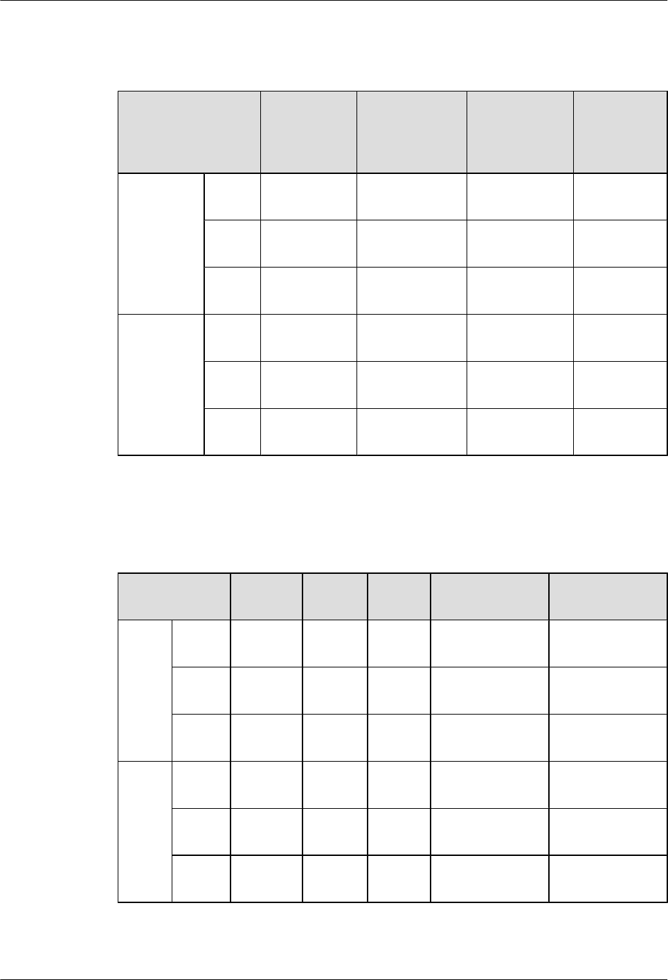
Matching between voice cards and software versions
Table 8-5 Matching between voice cards and software versions
Model&Version 4FXS1FXO 2BST(SIC) 2BST(WSIC) 16/32/64/128
-Channel
DSP
Module
ARV200R0
01C01
AR12
20-S
× × × ×
AR12
20W-S
× × × ×
AR22
20-S
√ √ × √
ARV200R0
02C00&AR
V200R002
C01
AR12
20-S
× × × ×
AR12
20W-S
× × × ×
AR22
20-S
√ √ √ √
Matching between xDSL/xPON cards and software versions
Table 8-6 Matching between xDSL/xPON cards and software versions
Model&Versi
on
ADSL-
A/M
ADSL-
B
4G.SH
DSL
1PON VDSL
ARV2
00R00
1C01
AR122
0-S
√ √ √ × ×
AR122
0W-S
√ √ √ × ×
AR222
0-S
√ √ √ × ×
ARV2
00R00
2C00
AR122
0-S
√ √ √ √ ×
AR122
0W-S
√ √ √ √ ×
AR222
0-S
√ √ √ √ ×
Huawei AR1200-S&2200-S Series Enterprise Routers
Hardware Description 8 List of Cards
Issue 03 (2012-04-20) Huawei Proprietary and Confidential
Copyright © Huawei Technologies Co., Ltd.
148
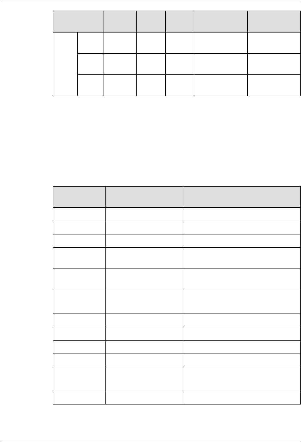
Model&Versi
on
ADSL-
A/M
ADSL-
B
4G.SH
DSL
1PON VDSL
ARV2
00R00
2C01
AR122
0-S
√ √ √ √ √
AR122
0W-S
√ √ √ √ √
AR222
0-S
√ √ √ √ √
8.2 Power Consumption and Weight
This section describes the power consumption and weight of cards supported by the AR routers.
Table 8-7 describes the power consumption and weight of cards supported by the AR routers.
The table describes the power consumption of the cards operating at 25°C (80°F).
Table 8-7 Power consumption and weight of cards supported by the AR1200-S
Card Name Maximum Power
Consumption
Weight
8FE1GE 12.036 W 0.6 kg (1.33 lb)
1GEC 2.28 W 0.25 kg (0.55 lb)
2FE 3.01 W 0.3 kg (0.67 lb)
1E1T1-M/
2E1T1-M
7 W 0.3 kg (0.67 lb)
1E1T1-F/2E1T1-
F
7 W 0.3 kg (0.67 lb)
1SA/2SA l1SA: 10 W
l2SA: 11.7 W
0.3 kg (0.67 lb)
8AS 8.9 W 0.6 kg (1.33 lb)
1BST 12 W 0.3 kg (0.67 lb)
2BST 16.8 W 0.3 kg (0.67 lb)
4FXS1FXO 12.78 W 0.3 kg (0.67 lb)
ADSL-A/M
ADSL-B
5.4 W 0.3 kg (0.67 lb)
4G.SHDSL 8.2 W 0.35 kg (0.77 lb)
Huawei AR1200-S&2200-S Series Enterprise Routers
Hardware Description 8 List of Cards
Issue 03 (2012-04-20) Huawei Proprietary and Confidential
Copyright © Huawei Technologies Co., Ltd.
149

9 List of Interface Attributes
About This Chapter
This section describes the interface attributes supported by the AR routers.
9.1 Electrical Interfaces
This section describes the attributes of electrical interfaces.
9.2 GE/PON Optical Interface Attributes
This section describes the attributes of GE/PON optical interfaces.
9.3 CPOS Interface Attributes
This section describes the CPOS interface attributes.
9.4 E1 Interface Attributes
This section describes the attributes of E1 interfaces.
9.5 T1 Interface Attributes
This section describes the attributes of T1 interfaces.
9.6 Synchronous/Asynchronous Serial Interface Attributes
This section describes the attributes of synchronous/asynchronous serial interfaces.
9.7 ISDN S/T Interface Attributes
This section describes ISDN S/T interface attributes.
9.8 FXS/FXO Interface Attributes
This section describes the attributes of FXS/FXO interfaces.
9.9 ADSL2/ADSL2+/G.SHDSL Interface Attributes
This section describes the attributes of ADSL2/ADSL2+/G.SHDSL interfaces.
9.10 Attributes of the Console Interface
This section describes the attributes of the console interface.
9.11 Attributes of the USB Interface
This section describes the attributes of the USB interface.
9.12 3G Interface Attributes
This section describes the attributes of 3G interfaces.
Huawei AR1200-S&2200-S Series Enterprise Routers
Hardware Description 9 List of Interface Attributes
Issue 03 (2012-04-20) Huawei Proprietary and Confidential
Copyright © Huawei Technologies Co., Ltd.
150

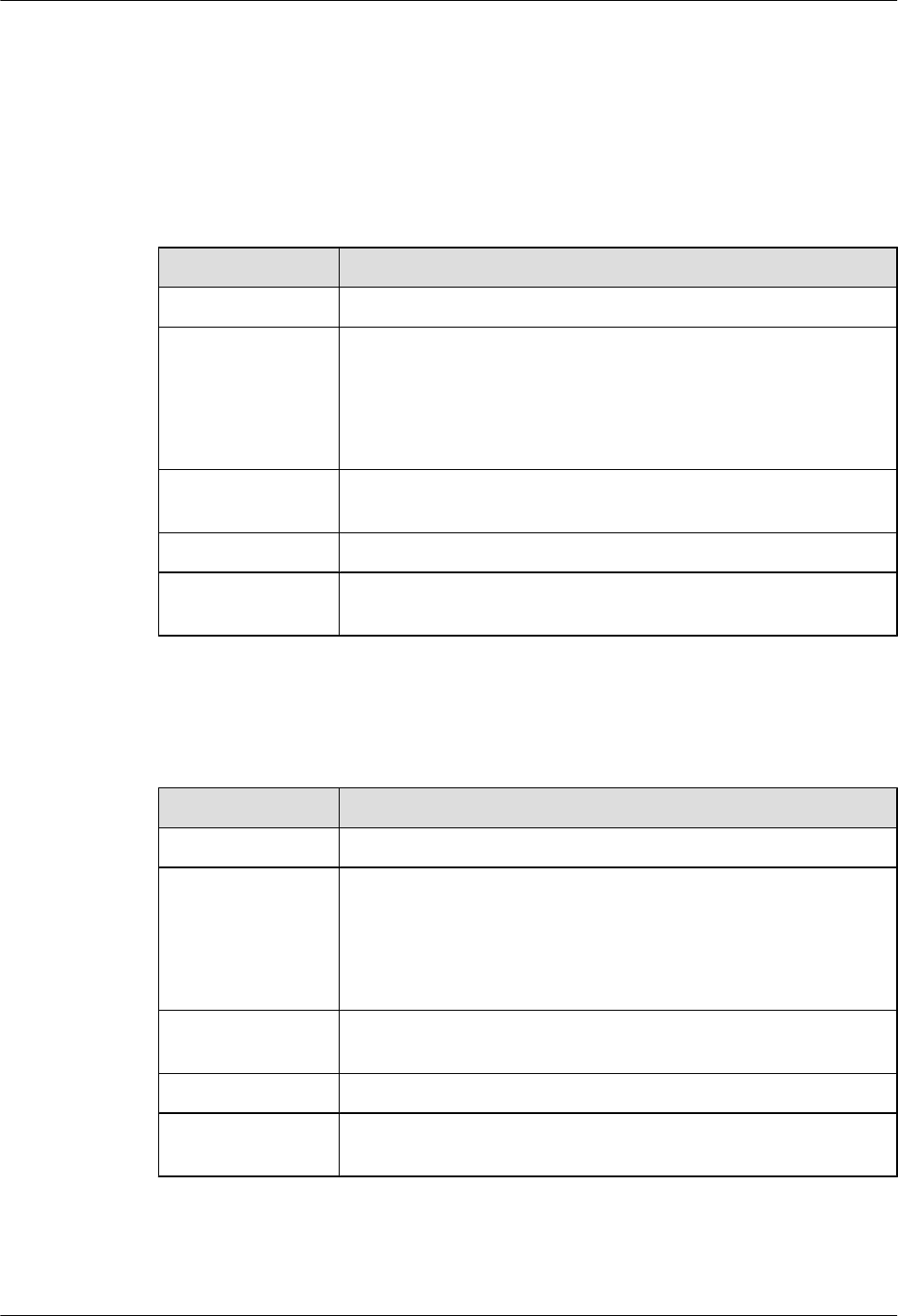
9.1 Electrical Interfaces
This section describes the attributes of electrical interfaces.
Table 9-1 describes the attributes of 10BASE-TX/100BASE-TX electrical interfaces.
Table 9-1 Attributes of 10BASE-TX/100BASE-TX electrical interfaces
Item Description
Connector type RJ45
Interface attribute MDI/MDIX
NOTE
lThe interfaces of most network cards are medium dependent interfaces
(MDIs).
lMDIX interfaces are usually used on hubs or LAN switches.
Standards
compliance
IEEE802.3, IEEE802.3u, IEEE802.3ab
Frame format Ethernet_II, Ethernet_SAP, or Ethernet_SNAP
Network layer
protocol
IP
Table 9-2 describes the attributes of 1000BASE-T electrical interfaces.
Table 9-2 Attributes of 1000BASE-T electrical interfaces
Item Description
Connector type RJ45
Interface attribute MDI/MDIX
NOTE
lThe interfaces of most network cards are medium dependent interfaces
(MDIs).
lMDIX interfaces are usually used on hubs or LAN switches.
Standards
compliance
IEEE802.3, IEEE802.3u, IEEE802.3ab
Frame format Ethernet_II, Ethernet_SAP, or Ethernet_SNAP
Network layer
protocol
IP
Huawei AR1200-S&2200-S Series Enterprise Routers
Hardware Description 9 List of Interface Attributes
Issue 03 (2012-04-20) Huawei Proprietary and Confidential
Copyright © Huawei Technologies Co., Ltd.
152
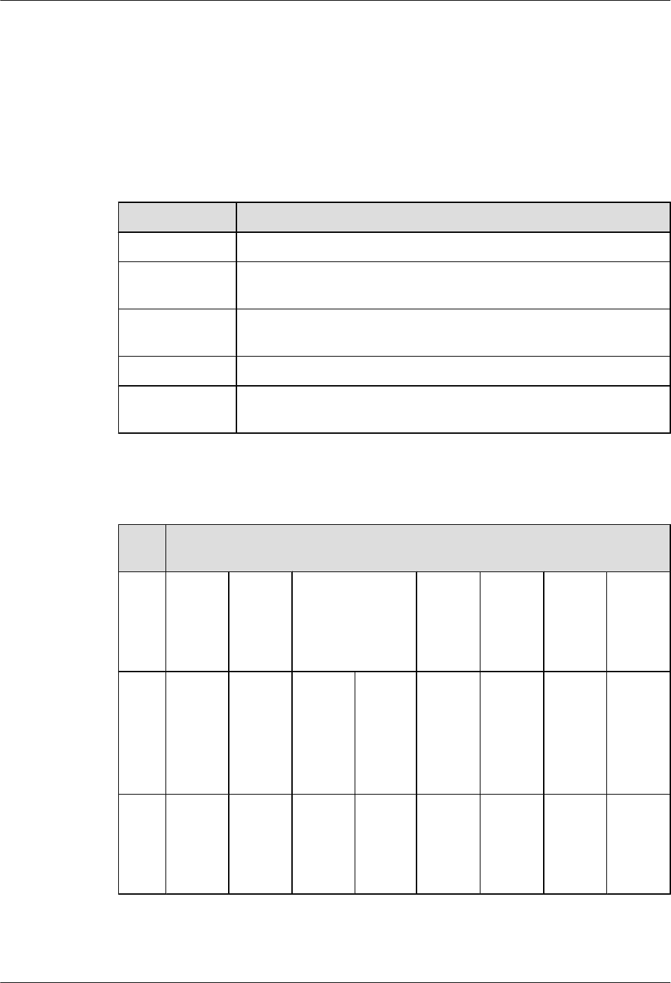
9.2 GE/PON Optical Interface Attributes
This section describes the attributes of GE/PON optical interfaces.
A GE optical interface can be connected to an optical module. Table 9-3 and Table 9-4 describe
the attributes of optical interfaces and optical modules.
Table 9-3 Attributes of the 100/1000BASE-X GE optical interface
Attribute Description
Connector type LC/PC
Optical interface
attribute
Depending on the SFP optical module.
Standards
compliance
IEEE 802.3ab
Frame format Ethernet_II, Ethernet_SAP, or Ethernet_SNAP
Network layer
protocol
IP
Table 9-4 Attributes of the SFP optical module (100/1000 Mbit/s) supported by the GE optical
interface
Attri
bute
Description
Tran
smiss
ion
dista
nce
500 m 10 km 10 km (single-
mode bidirectional
fiber)
40 km 40 km 80 km 100 km
Cent
er
wave
lengt
h
850 nm 1310
nm
Tx:
1310
nm
Rx:
1490
nm
Tx:
1490
nm
Rx:
1310
nm
1310
nm
1550
nm
1550
nm
1550
nm
Tran
smitt
ing
powe
r
-9.5
dBm to
-2.5
dBm
-9.0
dBm to
-3.0
dBm
-9.0
dBm to
-3.0
dBm
-9.0
dBm to
-3.0
dBm
-5.0
dBm to
0 dBm
-5.0
dBm to
0 dBm
-2.0
dBm to
5.0
dBm
0 dBm
to 5
dBm
Huawei AR1200-S&2200-S Series Enterprise Routers
Hardware Description 9 List of Interface Attributes
Issue 03 (2012-04-20) Huawei Proprietary and Confidential
Copyright © Huawei Technologies Co., Ltd.
153
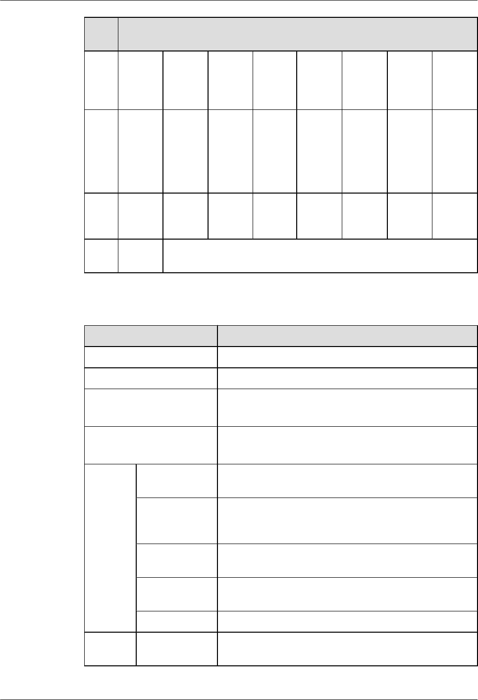
Attri
bute
Description
Rece
iver
sensi
tivity
-17.0
dBm
-20.0
dBm
-19.5
dBm
-19.5
dBm
-23
dBm
-22
dBm
-23.0
dBm
-30.0
dBm
Over
load
optic
al
powe
r
0 dBm -3.0
dBm
-3.0
dBm
-3.0
dBm
-3.0
dBm
-3.0
dBm
-3.0
dBm
-9.0
dBm
Extin
ction
ratio
9 dB 9 dB 6 dB 6 dB 9 dB 8.5 dB 9 dB 8 dB
Fiber
type
Multi-
mode
Single-mode
Table 9-5 Attributes of the SFP optical module supported by the PON optical interface
Attribute Description
Connector type SC/PC connector (SFP encapsulation)
Transport mode Single-mode bidirectional
Transmission rate lDownstream transmission rate of 2488 Mbit/s
lUpstream transmission rate of 1244 Mbit/s
Standards compliance ITU-T G.984.2 CLASS B+
ITU-T G.984.5 WBF
Sending
end
Center
wavelength
1290 nm to 1330 nm
Average
transmitting
optical power
0.5 dBm to 5 dBm
Average turn-off
optical power
-45 dBm
Side-mode
suppression ratio
30 dB
Extinction ratio 10 dB to 15 dB
Receivin
g end
Overload power -8 dBm
Huawei AR1200-S&2200-S Series Enterprise Routers
Hardware Description 9 List of Interface Attributes
Issue 03 (2012-04-20) Huawei Proprietary and Confidential
Copyright © Huawei Technologies Co., Ltd.
154
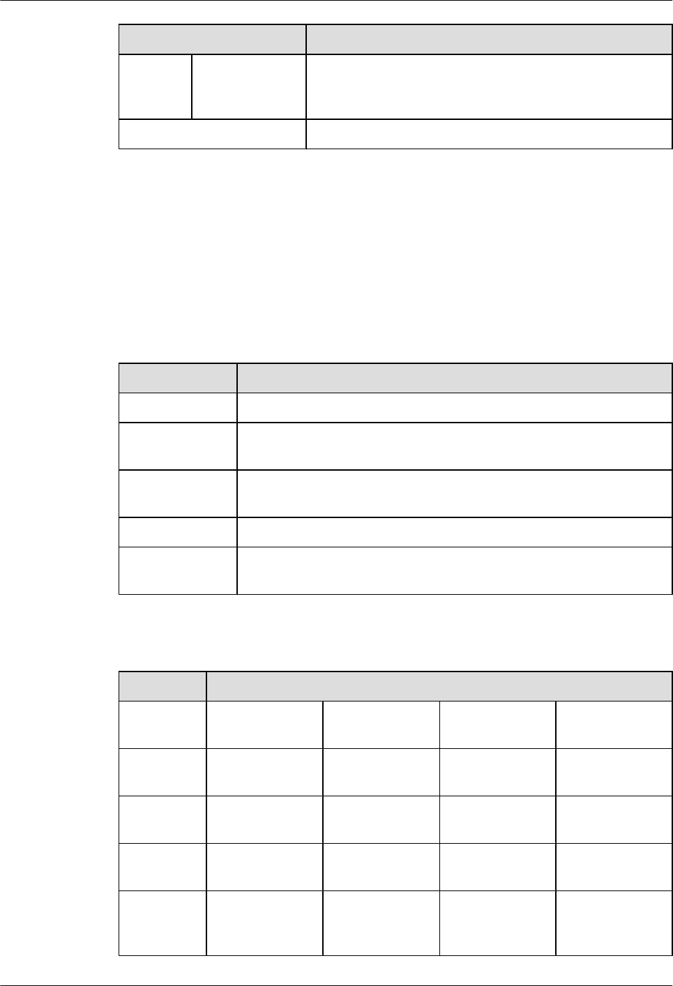
Attribute Description
Input
wavelength
range
1480 nm to 1500 nm
Operating temperature 0°C to 70°C
9.3 CPOS Interface Attributes
This section describes the CPOS interface attributes.
A CPOS optical interface can be connected to an optical module. Table 9-6 and Table 9-7
describe the attributes of optical interfaces and optical modules.
Table 9-6 CPOS interface attributes
Attribute Description
Connector type LC/PC
Optical interface
attribute
Depending on the SFP optical module
Standards
compliance
STM-1
Frame format SDH/SONET
Network layer
protocol
IP
Table 9-7 Attributes of the SFP optical module supported by the CPOS interface
Attribute Description
Transmissio
n distance
2 km 15 km 40 km 80 km
Center
wavelength
1310 nm 1310 nm 1310 nm 1550 nm
Transmittin
g power
-19.0 dBm to
-14.0 dBm
-15.0 dBm to 8.0
dBm
-15.0 dBm to 8.0
dBm
-3.0 dBm to 0
dBm
Receiver
sensitivity
-28.0 dBm -23.0 dBm -23.0 dBm -32.98 dBm
Overload
optical
power
-14.0 dBm -10.17 dBm -8.0 dBm -8.0 dBm
Huawei AR1200-S&2200-S Series Enterprise Routers
Hardware Description 9 List of Interface Attributes
Issue 03 (2012-04-20) Huawei Proprietary and Confidential
Copyright © Huawei Technologies Co., Ltd.
155
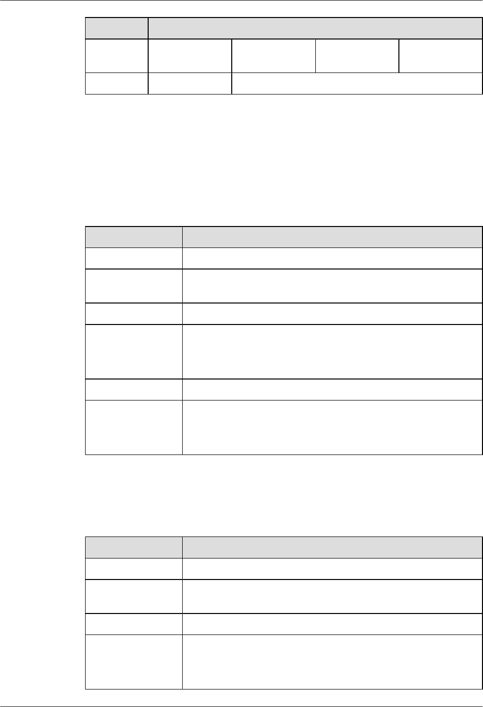
Attribute Description
Extinction
ratio
>10.0 dB 58.86 dB 14.08 dB 43.09 dB
Fiber type Multimode Single-mode
9.4 E1 Interface Attributes
This section describes the attributes of E1 interfaces.
Table 9-8 describes the attributes of channelized E1 interfaces.
Table 9-8 Attributes of channelized E1 interfaces
Attribute Description
Connector type DB9
Standards
compliance
G.703 or G.704
Transmission rate 2.048 Mbit/s
Cable type E1 75-ohm unbalanced coaxial cable
E1 120-ohm balanced twisted pair cable
E1 trunk cable extension
Working mode CE1, ISDN PRI, or VE1
Function Backup
Terminal access
ISDN PRI
Table 9-9 describes the attributes of unchannelized E1 interfaces.
Table 9-9 Attributes of unchannelized E1 interfaces
Attribute Description
Connector type DB9
Standards
compliance
G.703 or G.704
Transmission rate 2.048 Mbit/s
Cable type E1 75-ohm unbalanced coaxial cable
E1 120-ohm balanced twisted pair cable
E1 trunk cable extension
Huawei AR1200-S&2200-S Series Enterprise Routers
Hardware Description 9 List of Interface Attributes
Issue 03 (2012-04-20) Huawei Proprietary and Confidential
Copyright © Huawei Technologies Co., Ltd.
156
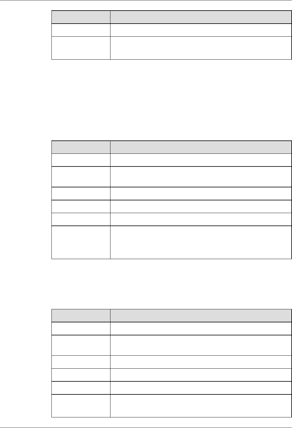
Attribute Description
Working mode Unchannelized E1
Function Backup
Terminal access
9.5 T1 Interface Attributes
This section describes the attributes of T1 interfaces.
Table 9-10 describes the attributes of channelized T1 interfaces.
Table 9-10 Attributes of channelized T1 interfaces
Attribute Description
Connector type DB9
Standards
compliance
G.703 or G.704
Transmission rate 1.544 Mbit/s
Cable type T1 100-ohm coaxial cable
Working mode CT1, ISDN PRI, or VT1
Function Backup
Terminal access
ISDN PRI
Table 9-11 describes the attributes of unchannelized T1 interfaces.
Table 9-11 Attributes of unchannelized T1 interfaces
Attribute Description
Connector type DB9
Standards
compliance
G.703 or G.704
Transmission rate 1.544 Mbit/s
Cable type T1 100-ohm coaxial cable
Working mode Unchannelized T1
Function Backup
Terminal access
Huawei AR1200-S&2200-S Series Enterprise Routers
Hardware Description 9 List of Interface Attributes
Issue 03 (2012-04-20) Huawei Proprietary and Confidential
Copyright © Huawei Technologies Co., Ltd.
157

9.6 Synchronous/Asynchronous Serial Interface Attributes
This section describes the attributes of synchronous/asynchronous serial interfaces.
Table 9-12 describes the attributes of synchronous/asynchronous serial interfaces.
Table 9-12 Attributes of synchronous/asynchronous serial interfaces
Attribute Description
Synchronous Serial Interface Asynchronous Serial
Interface
Connector
type
DB28
Standards
compliance
and working
mode
lV.24 DTE
lV.24 DCE
lV.35 DTE
lV.35 DCE
lX.21 DTE
lRS449 DTE
lRS449 DCE
lRS530 DTE
lRS530 DCE
RS232
Minimum
baud rate (bit/
s)
1200 1200 600
Maximum
baud rate (bit/
s)
64 k 2.048 M 115.2 k
Cable type lV.24 DTE cable
lV.24 DCE cable
lV.35 DTE cable
lV.35 DCE cable
lX.21 DTE cable
lRS449 DTE cable
lRS449 DCE cable
lRS530 DTE cable
lRS530 DCE cable
Function DDN leased line lModem dial-up
lBackup
Terminal access lAsynchronous leased line
lTerminal access
Huawei AR1200-S&2200-S Series Enterprise Routers
Hardware Description 9 List of Interface Attributes
Issue 03 (2012-04-20) Huawei Proprietary and Confidential
Copyright © Huawei Technologies Co., Ltd.
158

Table 9-13 describes the attributes of asynchronous serial interfaces.
Table 9-13 Attributes of asynchronous serial interfaces
Attribute Description
Connector type RJ45
Standards compliance and
working mode
RS232
Minimum baud rate (bit/s) 300
Maximum baud rate (bit/s) 115.2 k
Cable type Customized RJ45 cable
Function lModem dial-up
lBackup
lAsynchronous leased line
lTerminal access
9.7 ISDN S/T Interface Attributes
This section describes ISDN S/T interface attributes.
Table 9-14 lists ISDN S/T interface attributes.
Table 9-14 ISDN S/T interface attributes
Item Description
Connector RJ45
Standards compliance ITU-T I.430, Q.921, Q.931
Rate 192 kbit/s
Bandwidth 0 to 100 MHz
Cable lTE: standard ISDN S/T interface cables (straight-
through cables)
lNT: ISDN S/T interface crossover cables
9.8 FXS/FXO Interface Attributes
This section describes the attributes of FXS/FXO interfaces.
Table 9-15 describes the attributes of FXS/FXO (RJ11) interfaces on the 4FXS1FXO.
Huawei AR1200-S&2200-S Series Enterprise Routers
Hardware Description 9 List of Interface Attributes
Issue 03 (2012-04-20) Huawei Proprietary and Confidential
Copyright © Huawei Technologies Co., Ltd.
159
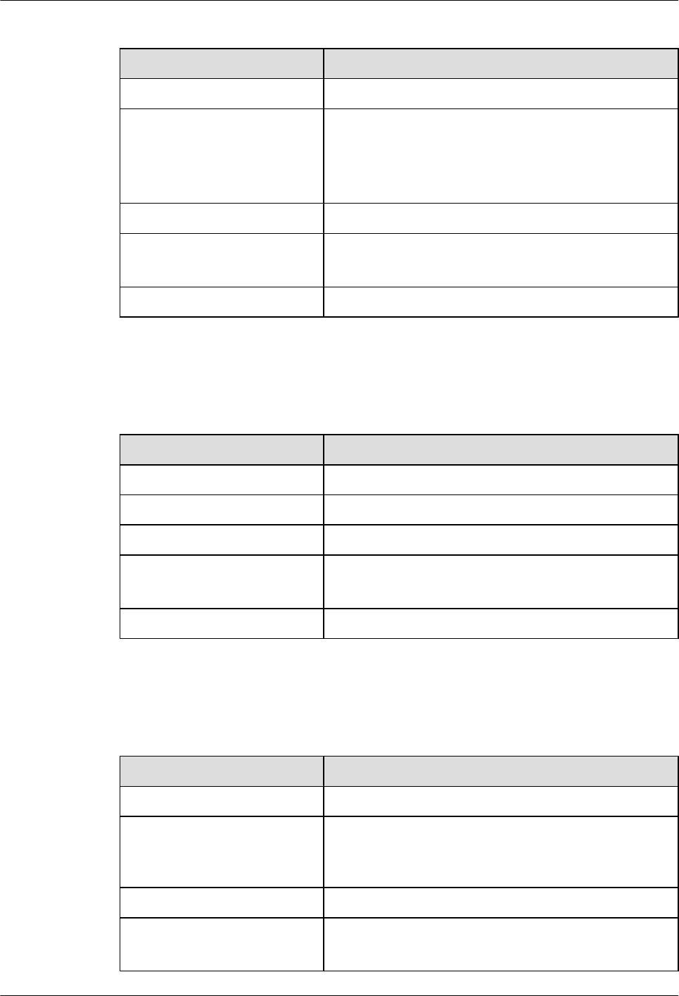
Table 9-15 Attributes of FXS/FXO (RJ11) interfaces
Attribute Description
Connector type RJ11
Standards compliance ITU Q.512 for FXS interfaces
ITU Q.552 for FXO interfaces
ITU K.20 for protection against overcurrent and
overvoltage
Cable type Regular telephone line
Dialing mode DTMF in accordance with GB3378
Pulse dialing
Bandwidth 300 Hz to 3400 Hz
Table 9-16 describes the attributes of FXS (DB68) interfaces on the 32FXS/16FXS.
Table 9-16 Attributes of FXS (DB68) interfaces
Attribute Description
Connector type DB68
Standards compliance IEEE 1284C Interface as a 36 contact connector
Cable type Twisted pair
Dialing mode DTMF in accordance with GB3378
Pulse dialing
Bandwidth 300 Hz to 3400 Hz
Table 9-17 describes the attributes of FXO (RJ11) interfaces on the 4FXO.
Table 9-17 Attributes of FXO (RJ11) interfaces
Attribute Description
Connector type RJ11
Standards compliance ITU Q.552 for FXO interfaces
ITU K.20 for protection against overcurrent and
overvoltage
Cable type Telephone cable
Dialing mode DTMF in accordance with GB3378
Pulse dialing
Huawei AR1200-S&2200-S Series Enterprise Routers
Hardware Description 9 List of Interface Attributes
Issue 03 (2012-04-20) Huawei Proprietary and Confidential
Copyright © Huawei Technologies Co., Ltd.
160
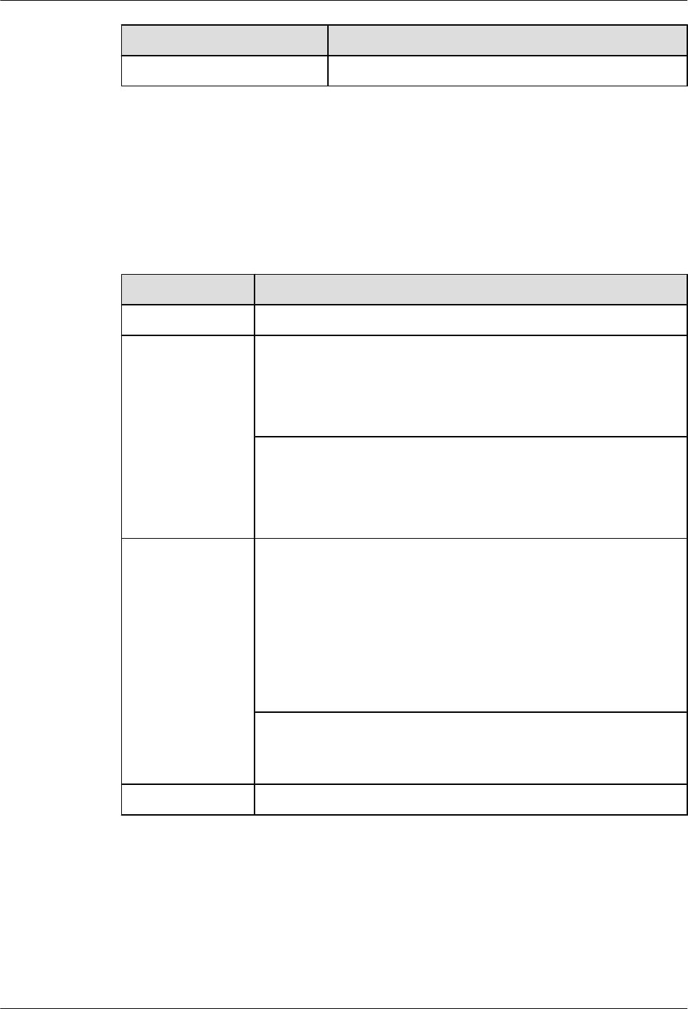
Attribute Description
Bandwidth 300 Hz to 3400 Hz
9.9 ADSL2/ADSL2+/G.SHDSL Interface Attributes
This section describes the attributes of ADSL2/ADSL2+/G.SHDSL interfaces.
Table 9-18 describes the attributes of ADSL2/ADSL2+ interfaces.
Table 9-18 Attributes of ADSL2/ADSL2+ interfaces
Attribute Description
Connector type RJ11
Standards
compliance
ADSL-A/M:
ITU-T 992.1 G.DMT
ITU-T 992.3
ITU-T 992.5
ADSL-B:
ITU-T 992.1 G.DMT ANSI T1.413 Issue 2
ITU-T 992.3
ITU-T 992.5
Transmission rate ADSL-A/M:
lADSL full rate mode (ITU-T 992.1 G.DMT): a downstream
transmission rate of 8 Mbit/s and an upstream transmission rate of
1024 kbit/s
lADSL2 full rate mode (ITU-T 992.3): a downstream transmission
rate of 12 Mbit/s and an upstream transmission rate of 1024 kbit/s
lADSL2+ full rate mode (ITU-T 992.5): a downstream transmission
rate of 24 Mbit/s and an upstream transmission rate of 1024 kbit/s
ADSL-B:
A downstream transmission rate of 8 Mbit/s and an upstream
transmission rate of 1024 kbit/s
Cable type Regular telephone line
Table 9-19 describes the attributes of G.SHDSL interfaces.
Huawei AR1200-S&2200-S Series Enterprise Routers
Hardware Description 9 List of Interface Attributes
Issue 03 (2012-04-20) Huawei Proprietary and Confidential
Copyright © Huawei Technologies Co., Ltd.
161
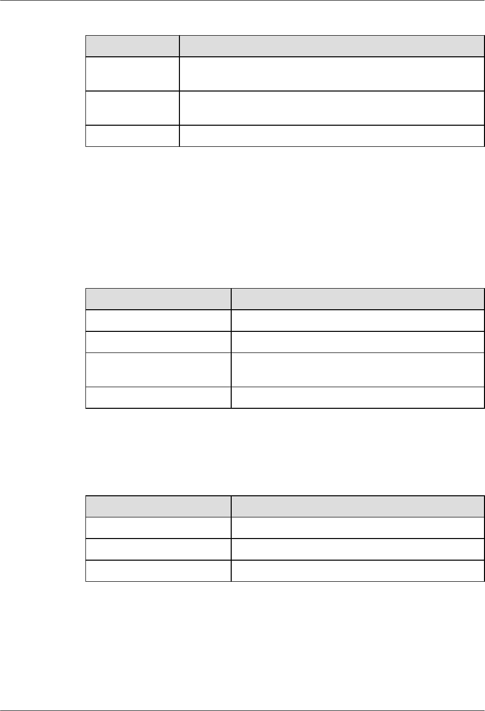
Table 9-19 Attributes of G.SHDSL interfaces
Attribute Description
Connector type One RJ45 connector on one end and four RJ11 connectors on the other
end
Standards
compliance
G.SHDSL.bit
Transmission rate 5.696 Mbit/s per pair
9.10 Attributes of the Console Interface
This section describes the attributes of the console interface.
Table 9-20 lists the attributes of the console interface.
Table 9-20 Attributes of the console interface
Item Description
Connector type RJ45
Standards compliance RS232
Operating mode Full duplex Universal Asynchronous Receiver/
Transmitter (UART)
Data equipment type Data Circuit-terminating Equipment (DCE)
Table 9-21 lists the attributes of the MiniUSB-B interface.
Table 9-21 Attributes of the MiniUSB-B interface
Item Description
Connector type MiniUSB-B, angle
Standards compliance USB1.0
Operating mode Device
9.11 Attributes of the USB Interface
This section describes the attributes of the USB interface.
Table 9-22 lists the attributes of the USB-A interface.
Huawei AR1200-S&2200-S Series Enterprise Routers
Hardware Description 9 List of Interface Attributes
Issue 03 (2012-04-20) Huawei Proprietary and Confidential
Copyright © Huawei Technologies Co., Ltd.
162
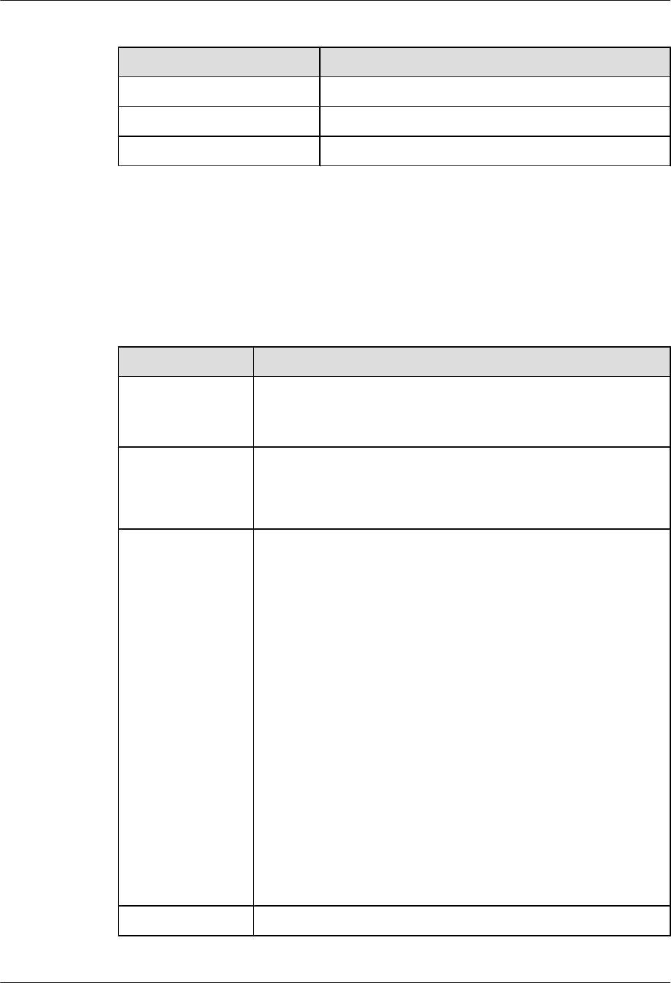
Table 9-22 Attributes of the USB-A interface
Item Description
Connector type USB-A
Standards compliance USB2.0, compatible with USB1.0 and USB1.1
Operating mode Host
9.12 3G Interface Attributes
This section describes the attributes of 3G interfaces.
Table 9-23 lists the attributes of 3G interfaces.
Table 9-23 3G interface attributes
Item Description
Connector SMA RF: connects to an antenna to provide wireless access.
mini USB: connects to a USB flash drive with third-party wireless
network test software, for example, Qualcomm CAIT.
Standards
compliance and
frequency bands
supported
GSM/GPRS/EDGE: 850/900/1800/1900 (MHz)
HSPA+/HSUPA/HSDPA/WCDMA: 2100/1900/900/850 (MHz)
Rate GSM CS:
lUpstream (Tx): 9.6kbit/s
lDownstream (Rx): 9.6kbit/s
GPRS/EDGE: Multi-slot Class 12, Class B
WCDMA CS:
lUpstream (Tx): 64 kbit/s
lDownstream (Rx): 64 kbit/s
WCDMA PS:
lUpstream (Tx): 384 kbit/s
lDownstream (Rx): 384 kbit/s
HSPA:
lUpstream (Tx): 5.76 Mbit/s
lDownstream (Rx): 14.4 Mbit/s
HSPA+:
lUpstream (Tx): 5.76 Mbit/s
lDownstream (Rx): 21 Mbit/s
Network protocol WCDMA/HSPA/GPRS/EDGE
Huawei AR1200-S&2200-S Series Enterprise Routers
Hardware Description 9 List of Interface Attributes
Issue 03 (2012-04-20) Huawei Proprietary and Confidential
Copyright © Huawei Technologies Co., Ltd.
163

9.13 VDSL Interface Attributes
This section describes the attributes of the VDSL interface.
Table 9-24 lists attributes of the VDSL interface.
Table 9-24 VDSL interface attributes
Item Description
Connector RJ11
Standards
compliance
VDSL standards:
ITU-T 993.2
ITU-T 992.5
ITU-T 992.3
ITU-T 992.1 G.DMT
Rate lADSL2+ full rate mode (ITU-T 992.3): a downstream transmission
rate of 12 Mbit/s and an upstream transmission rate of 1 Mbit/s
lVDSL2 mode (ITU-T 993.2): a downstream transmission rate of
100 Mbit/s and an upstream transmission rate of 50 kbit/s
lADSL2 full rate mode (ITU-T 992.5): a downstream transmission
rate of 24 Mbit/s and an upstream transmission rate of 1 Mbit/s
lADSL full rate mode (ITU-T 992.1 G.DMT): a downstream
transmission rate of 8 Mbit/s and an upstream transmission rate of
1 Mbit/s
Cable type Telephone cable
Huawei AR1200-S&2200-S Series Enterprise Routers
Hardware Description 9 List of Interface Attributes
Issue 03 (2012-04-20) Huawei Proprietary and Confidential
Copyright © Huawei Technologies Co., Ltd.
164