Huawei Technologies AR1220WIFI Access Router User Manual Hardware Description
Huawei Technologies Co.,Ltd Access Router Hardware Description
UserManual.wiki
>
Huawei Technologies
>
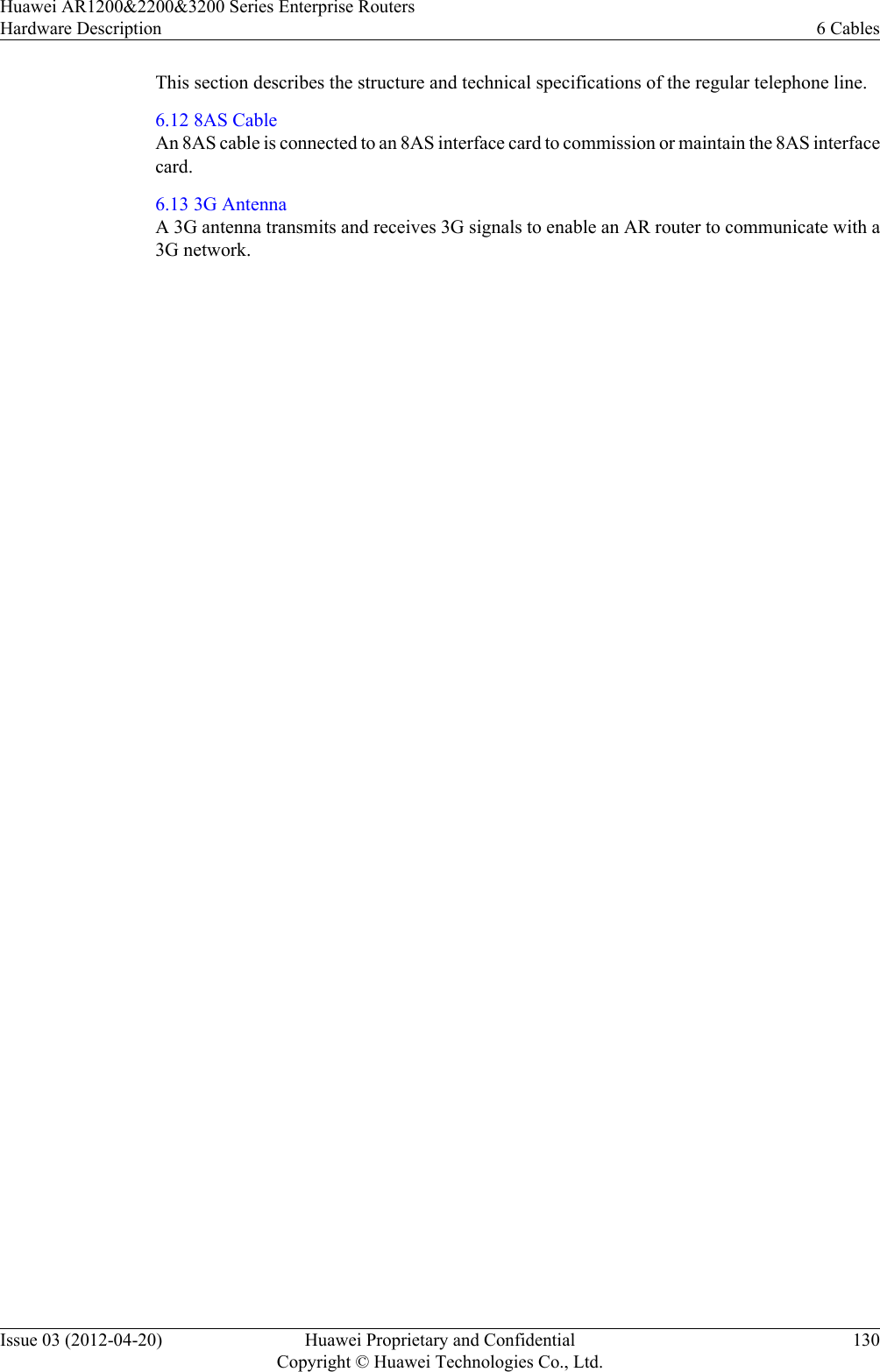
AR1220WIFI User Manual
>
User manual III
Contents
1.
User Manual
2.
User manual I
3.
User manual II
4.
User manual III
User manual III
Navigation menu
Upload a User Manual
Namespaces
Wiki Guide
HTML
PDF
Info
Views
User Manual
Discussion / Help
Navigation

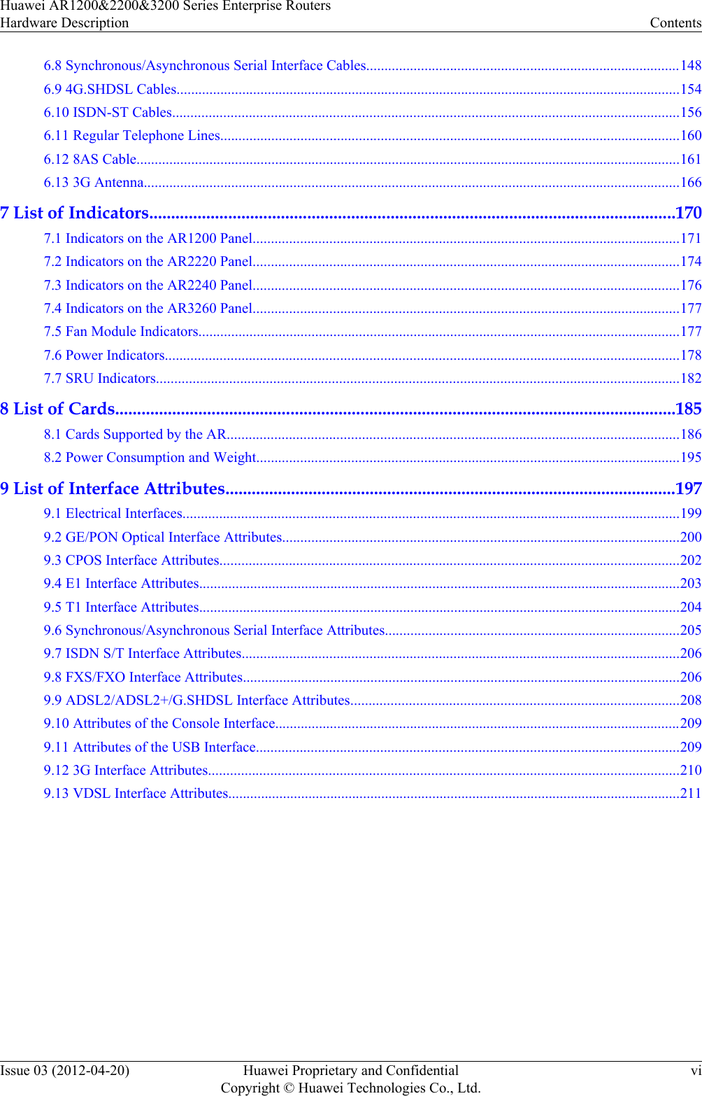
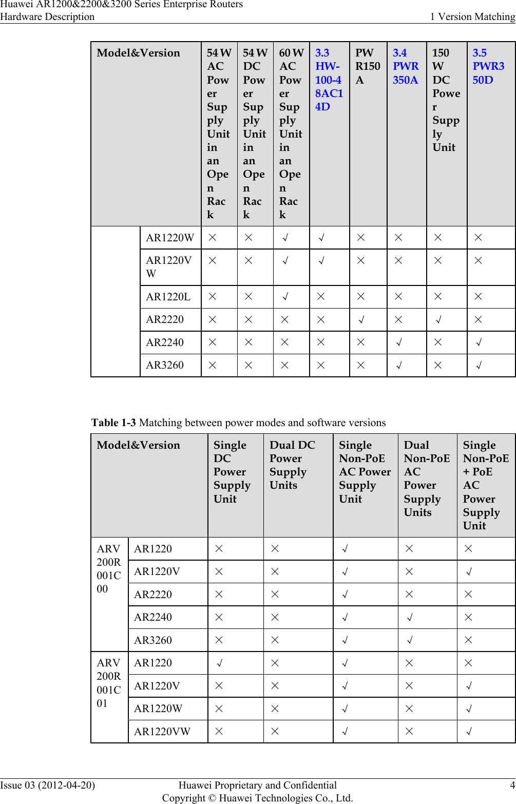
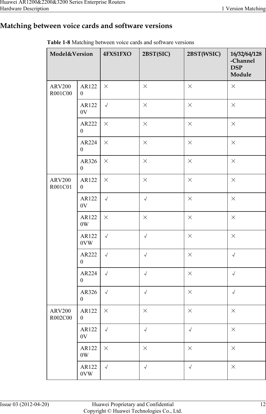
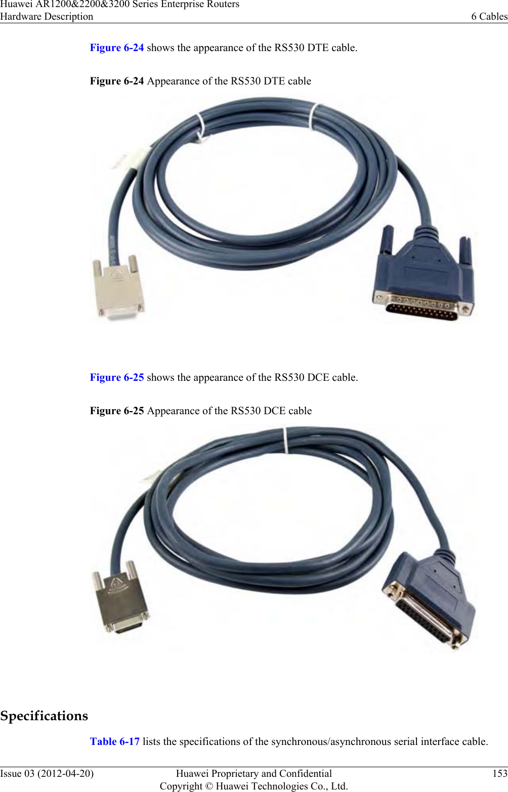
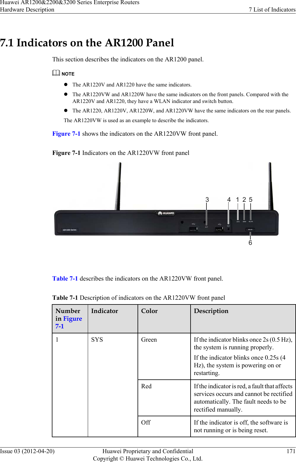
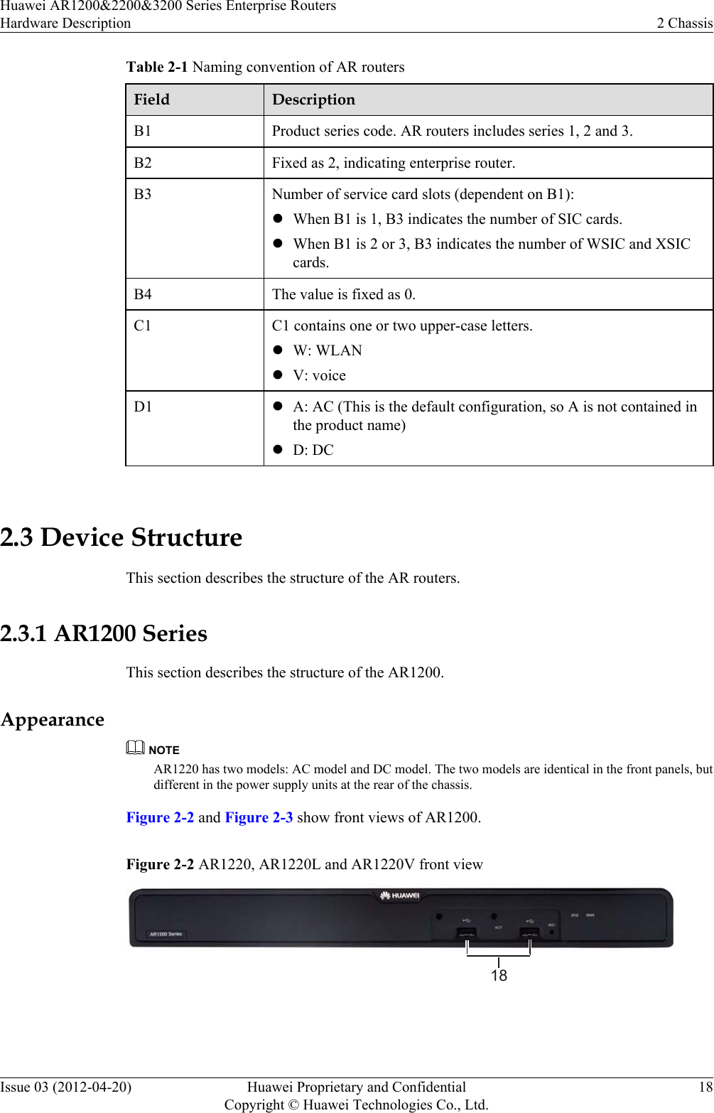
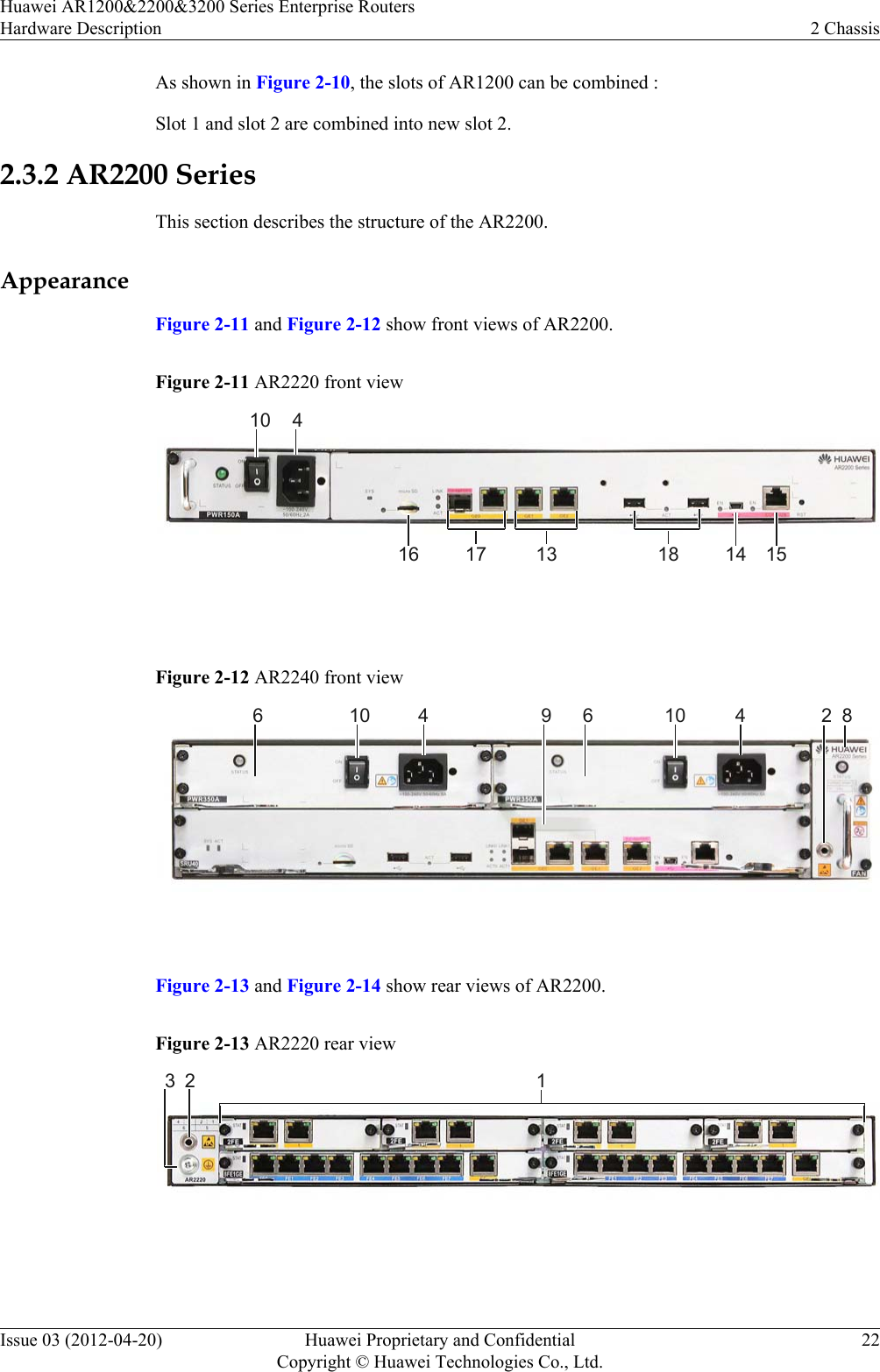
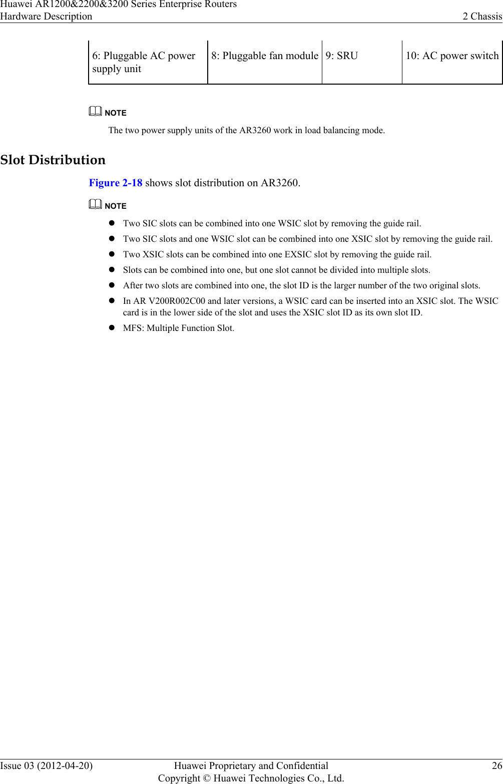
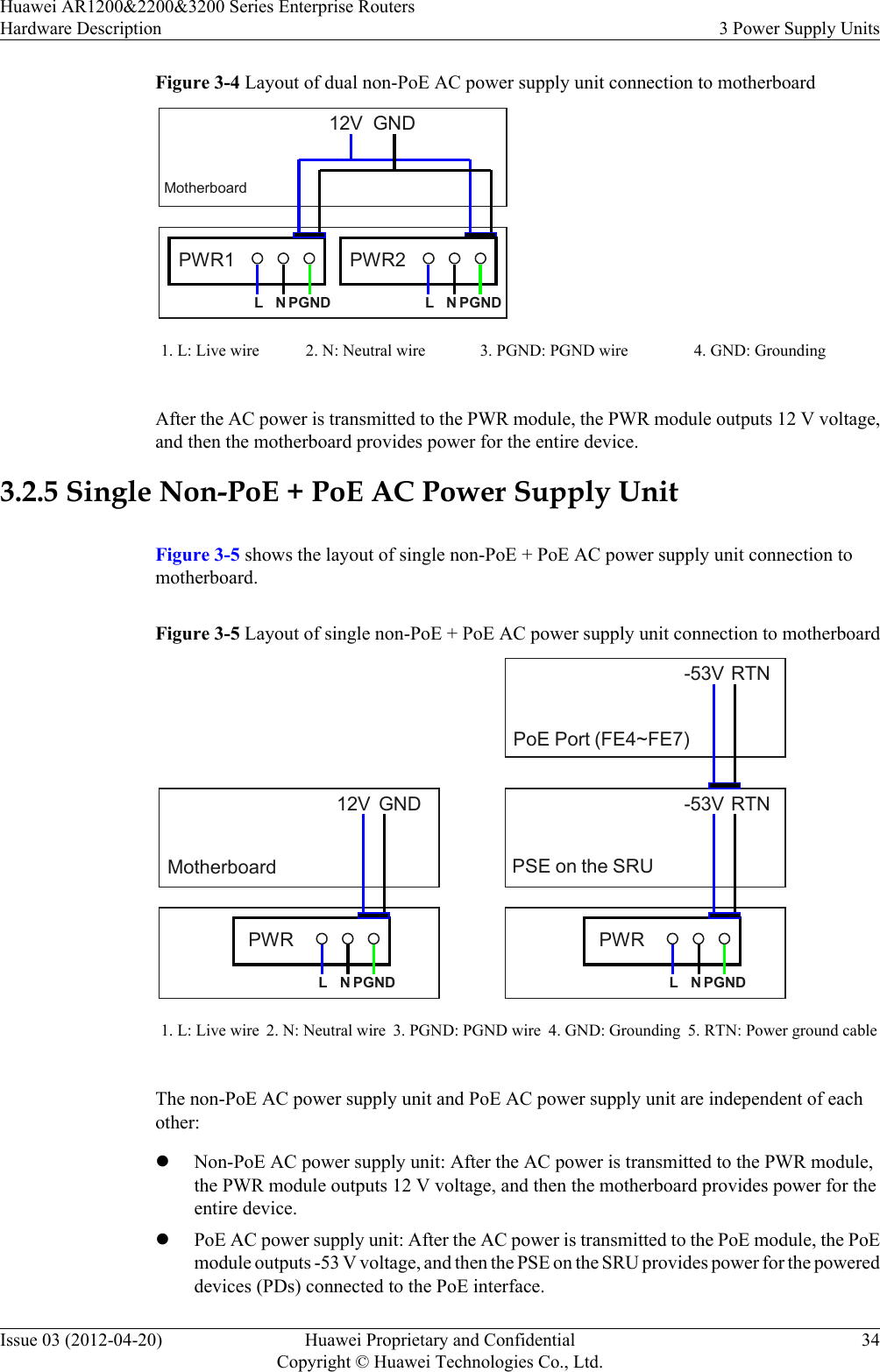
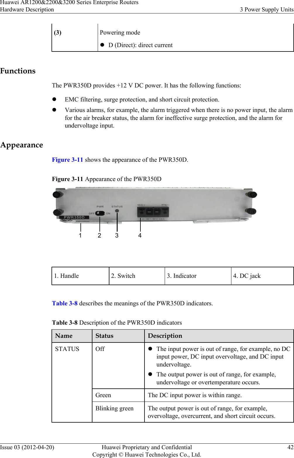
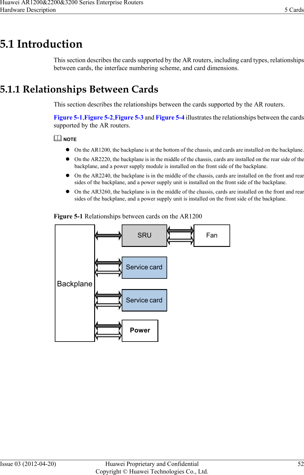
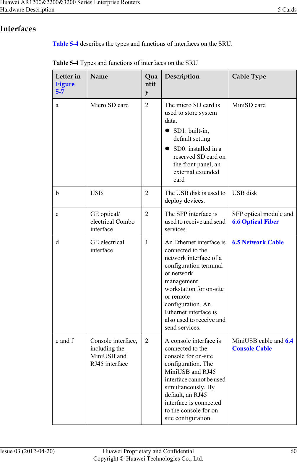
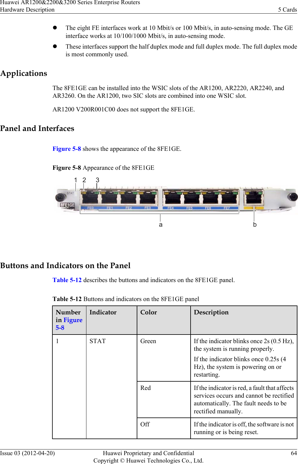
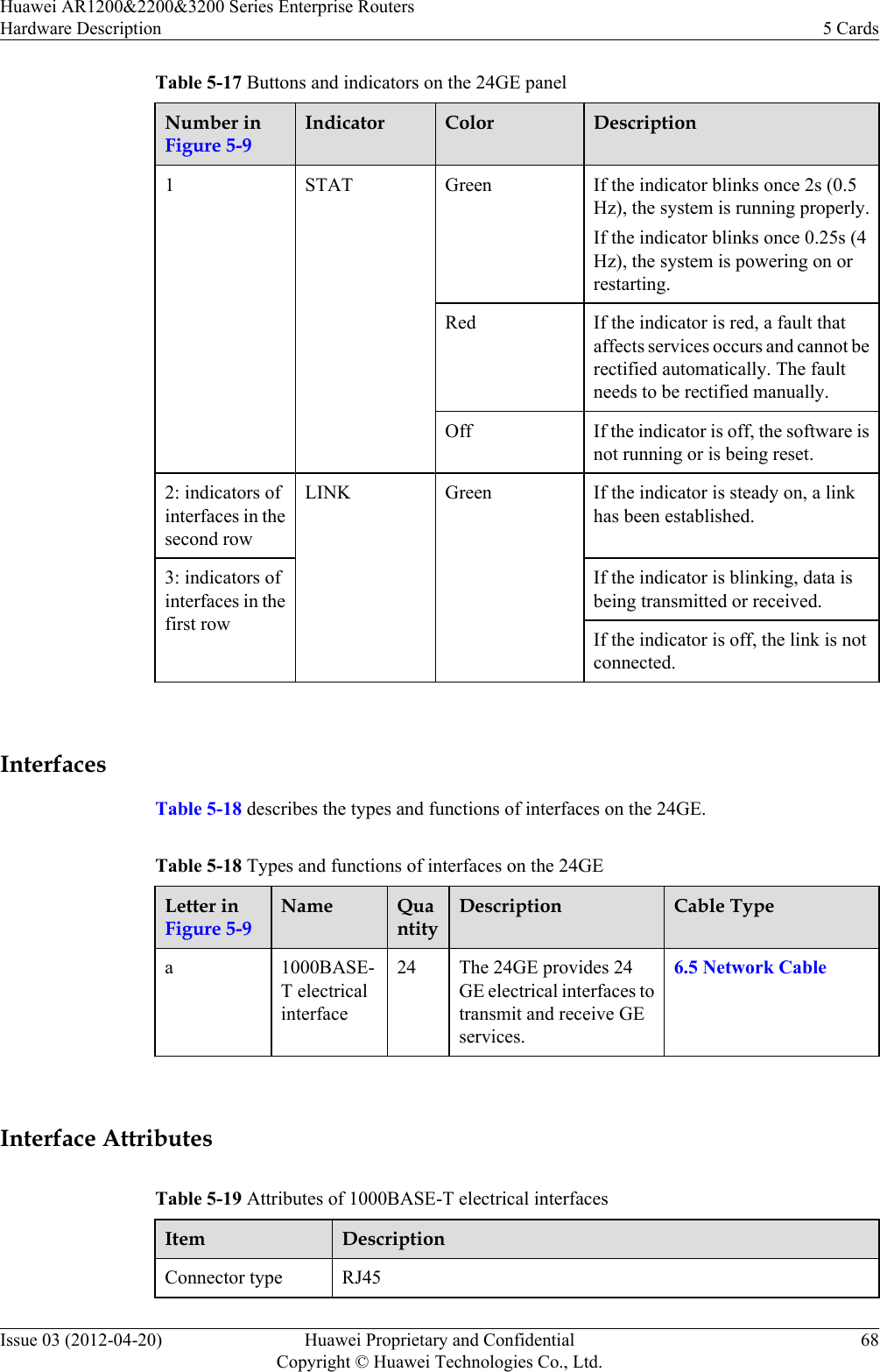
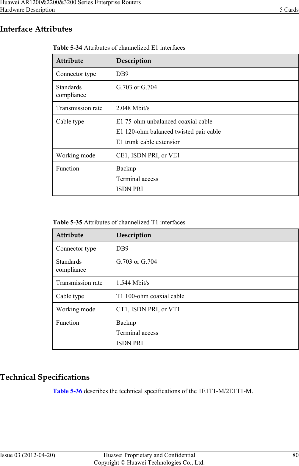
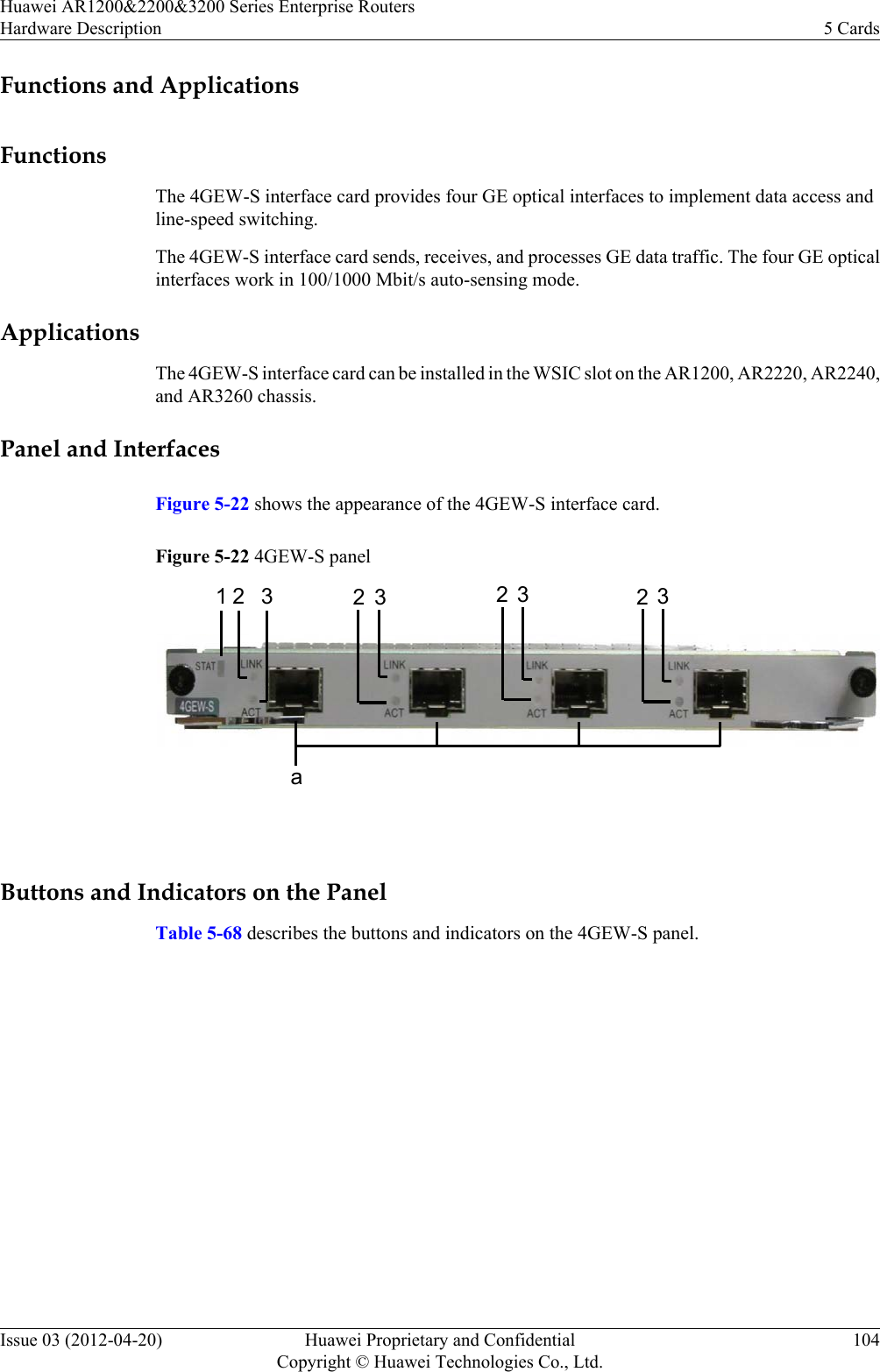
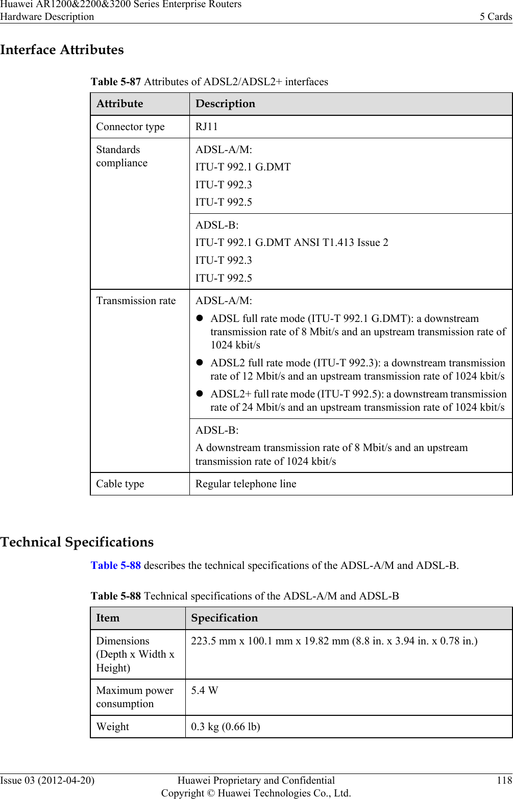
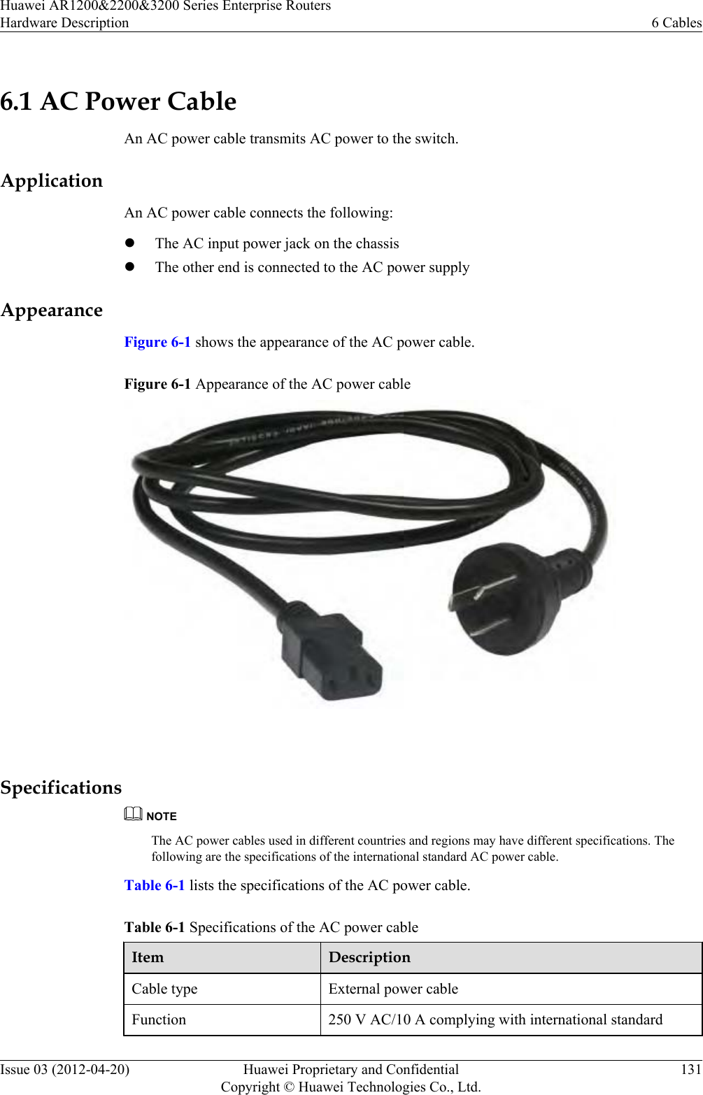
![2.1 IntroductionThis section briefly describes the AR routers and the models available.DescriptionHuawei AR Enterprise Router (AR router for short) are the next-generation routers integratingdata,voice, security, routing, switching, and virtual private network (VPN) functions. As anegress gateway for enterprises, the AR routers use the multi-core CPU processing capabilitiesand rapid expansibility.ModelsThe AR routers offer the following models.Model CharacteristicsAR1200 AR1220 The AR1220 is 1 U high (1 U = 44.45 mm [1.75 in.]), uses a 60 WAC power supply unit installed in an open rack, and supports two SICcards. The integrated SRU supports fixed 8FE interfaces and fixed2GE electrical interfaces.NOTElAR V200R001C00 uses the 54 W AC power supply unit installed in anopen rack.lAR V200R001C01 and later versions use the 60 W AC power supply unitinstalled in an open rack.AR1220VlCompared with the AR1220, the AR1220V supports 32-channelvoice and the PoE power supply unit can be installed on it. Thelast four FE interfaces (FE4-FE7) on the main control unit supportthe PoE function.lThe silkscreen on the rear side of AR1220V chassis is AR1220Vand a PoE power supply port is provided.AR1220WlCompared with the AR1220, the AR1220W supports the Wi-Fifunction and external PoE power supply unit. The last four FEinterfaces (FE4-FE7) on the main control unit support the PoEfunction.lThe silkscreen on the rear side of AR1220W chassis is AR1220Wand two antennas and a PoE power supply port are provided.AR1220VWlCompared with the AR1220, the AR1220VW supports 32-channel voice, Wi-Fi, and external PoE power supply unit. Thelast four FE interfaces (FE4-FE7) on the main control unit supportthe PoE function.lThe silkscreen on the rear side of AR1220VW chassis isAR1220VW and two antennas and a PoE power supply port areprovided.Huawei AR1200&2200&3200 Series Enterprise RoutersHardware Description 2 ChassisIssue 03 (2012-04-20) Huawei Proprietary and ConfidentialCopyright © Huawei Technologies Co., Ltd.16](https://usermanual.wiki/Huawei-Technologies/AR1220WIFI.User-manual-III/User-Guide-1716095-Page-23.png)
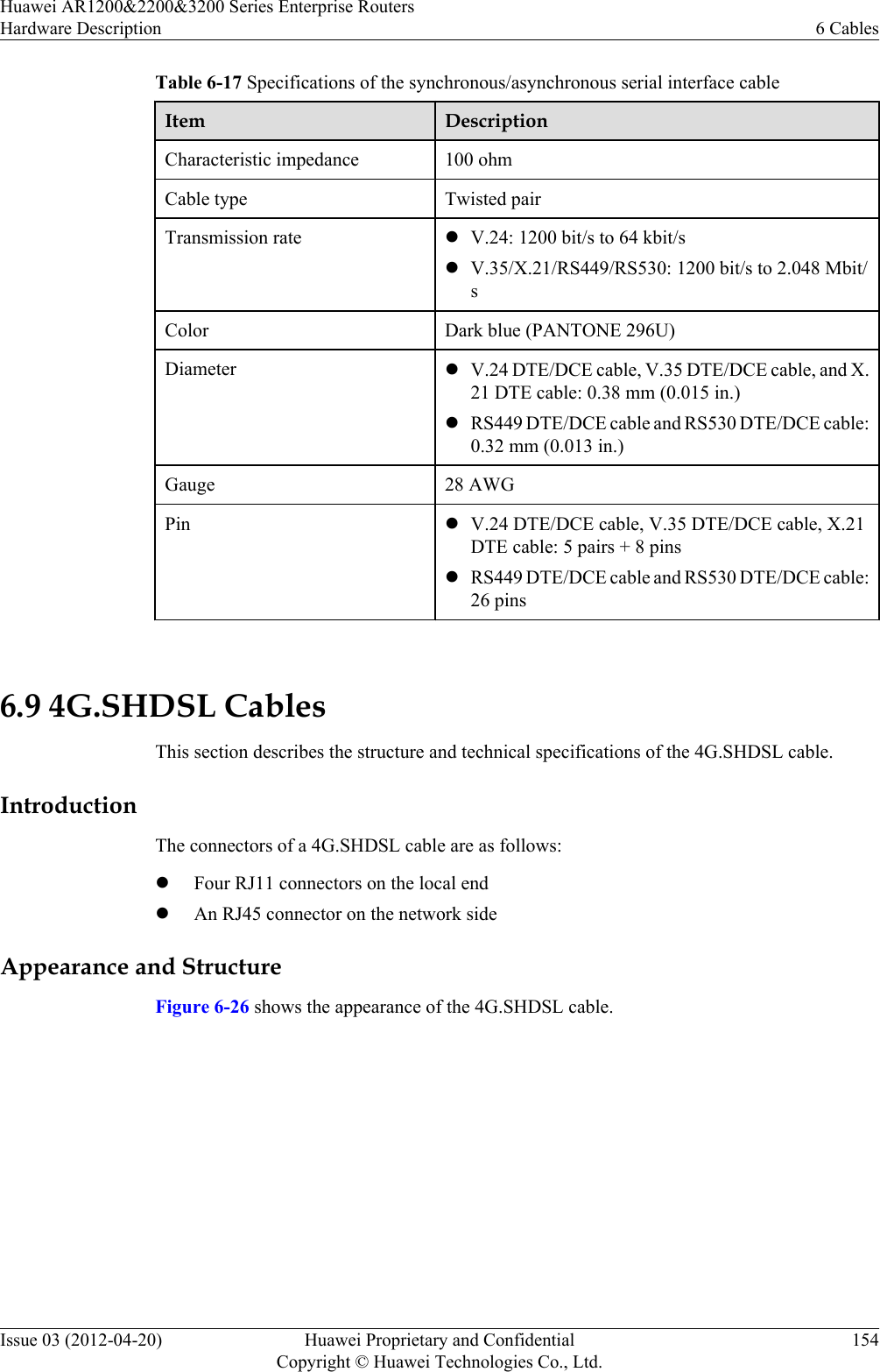
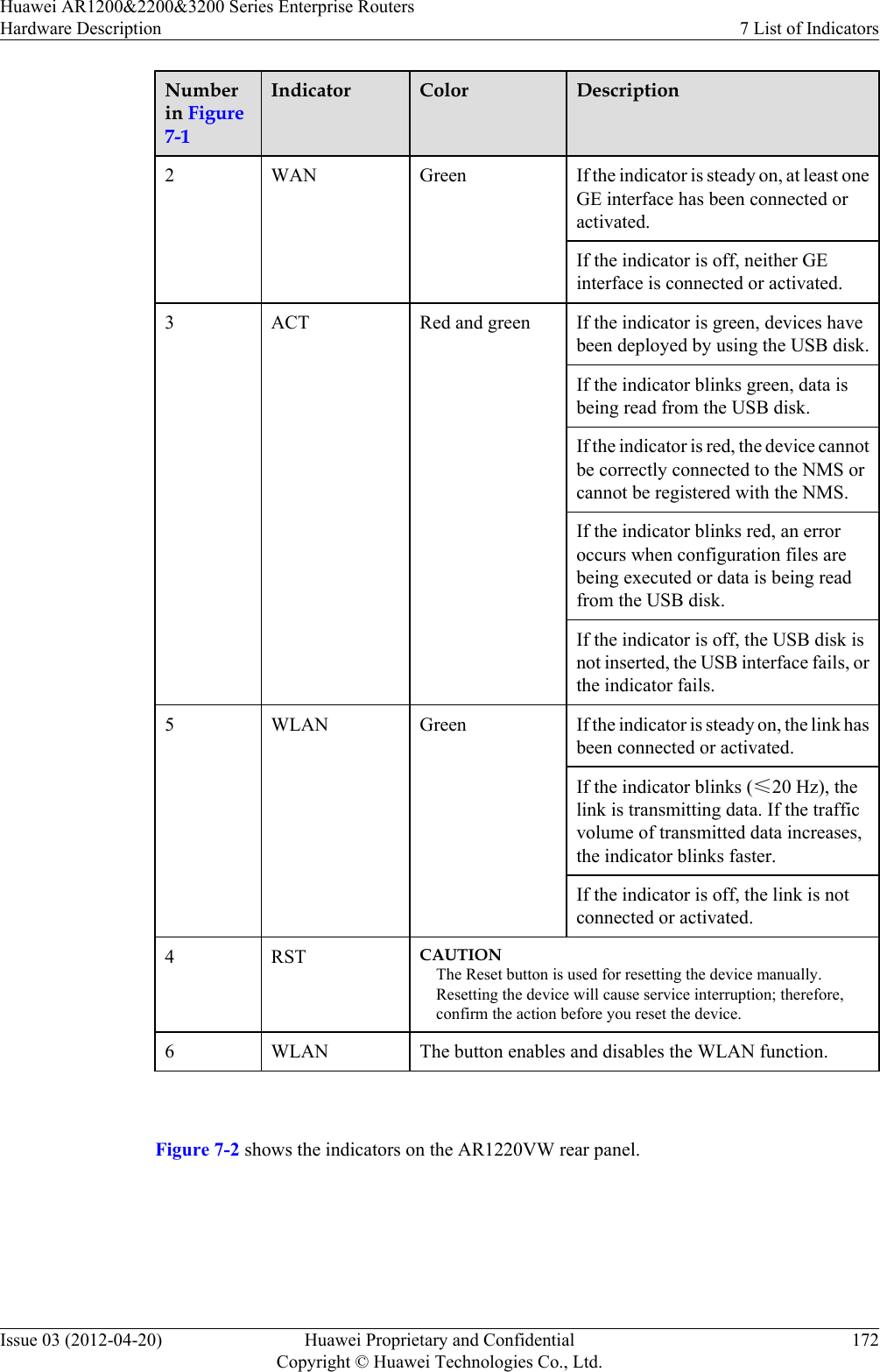
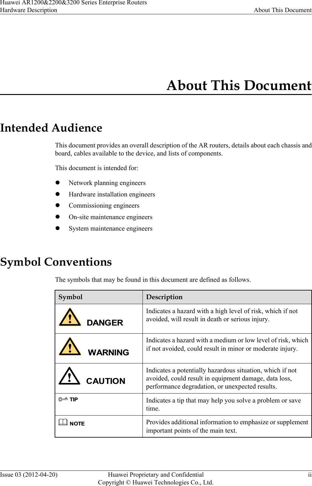
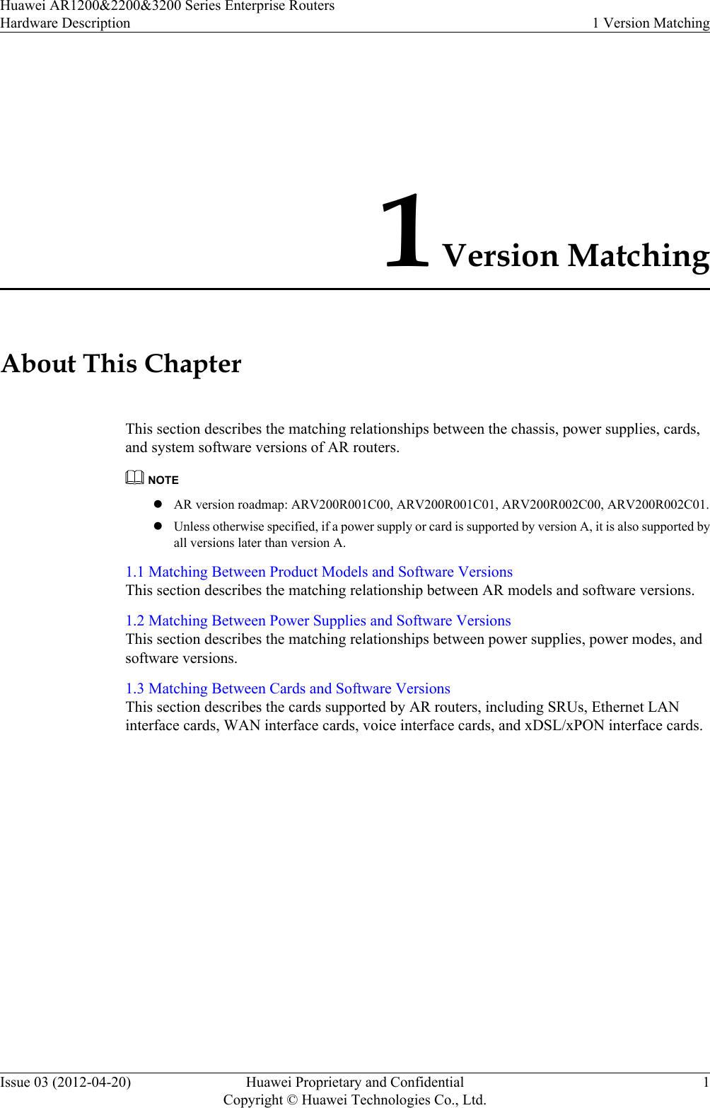
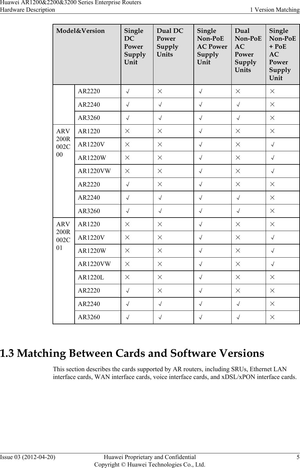
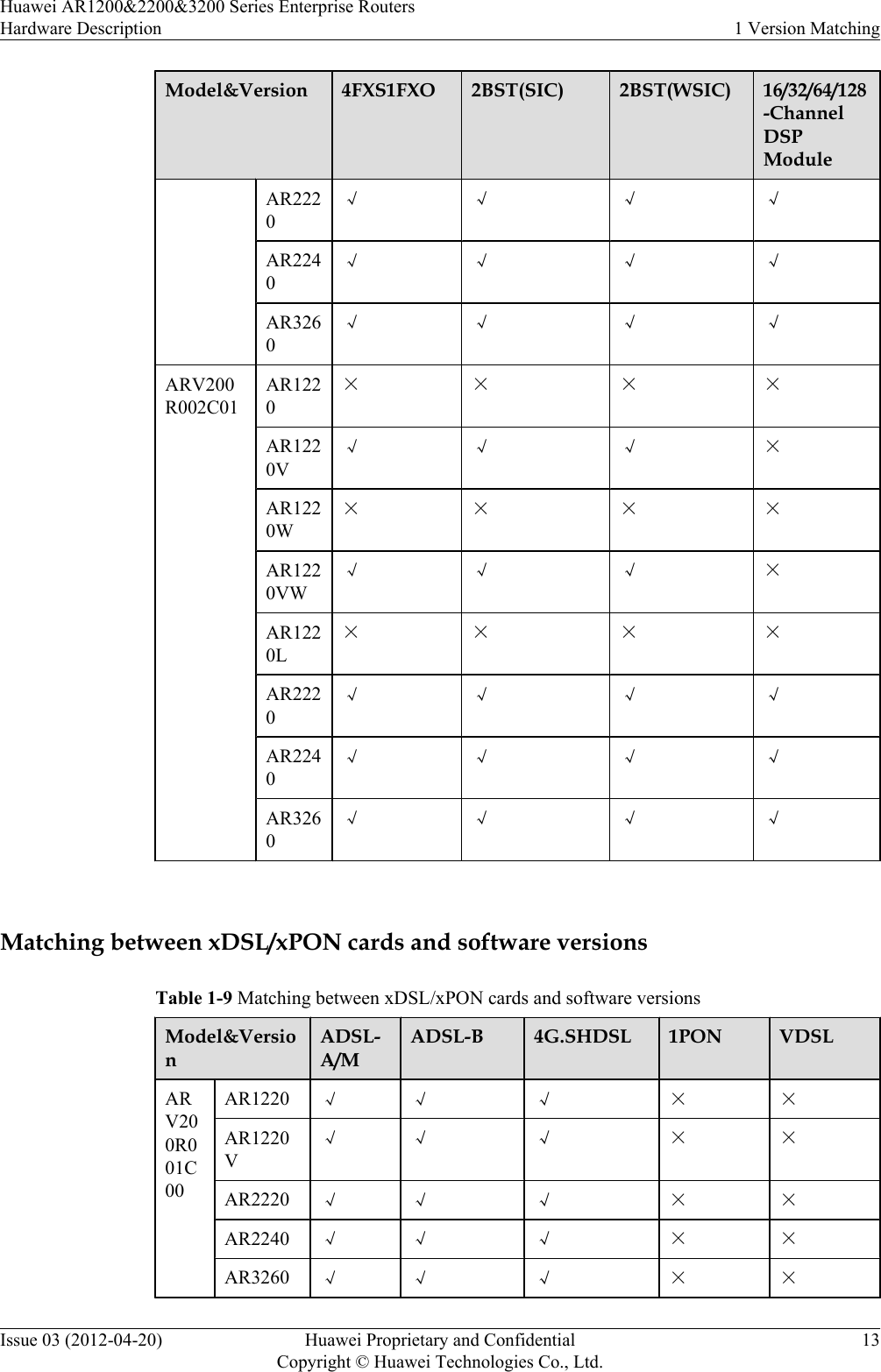
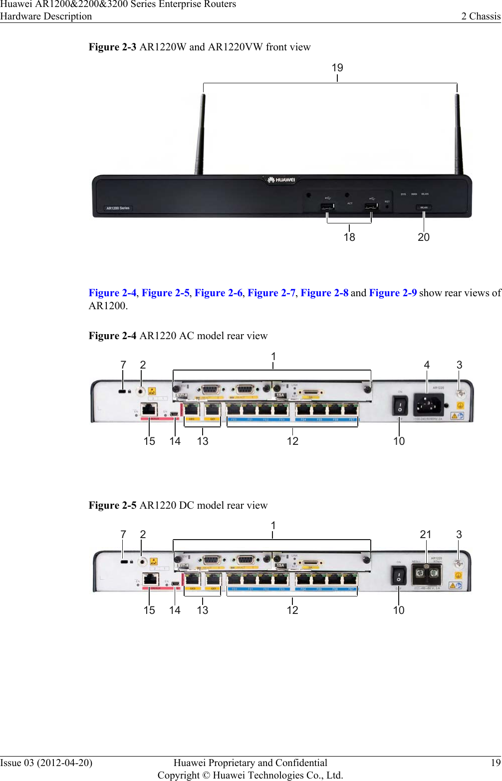
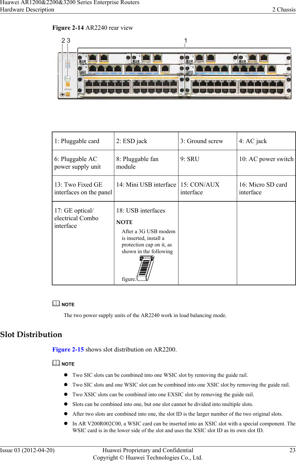
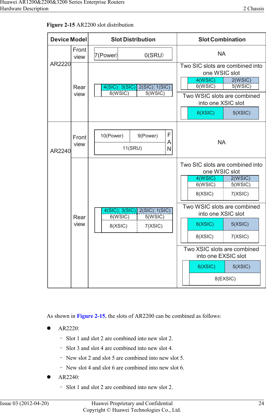
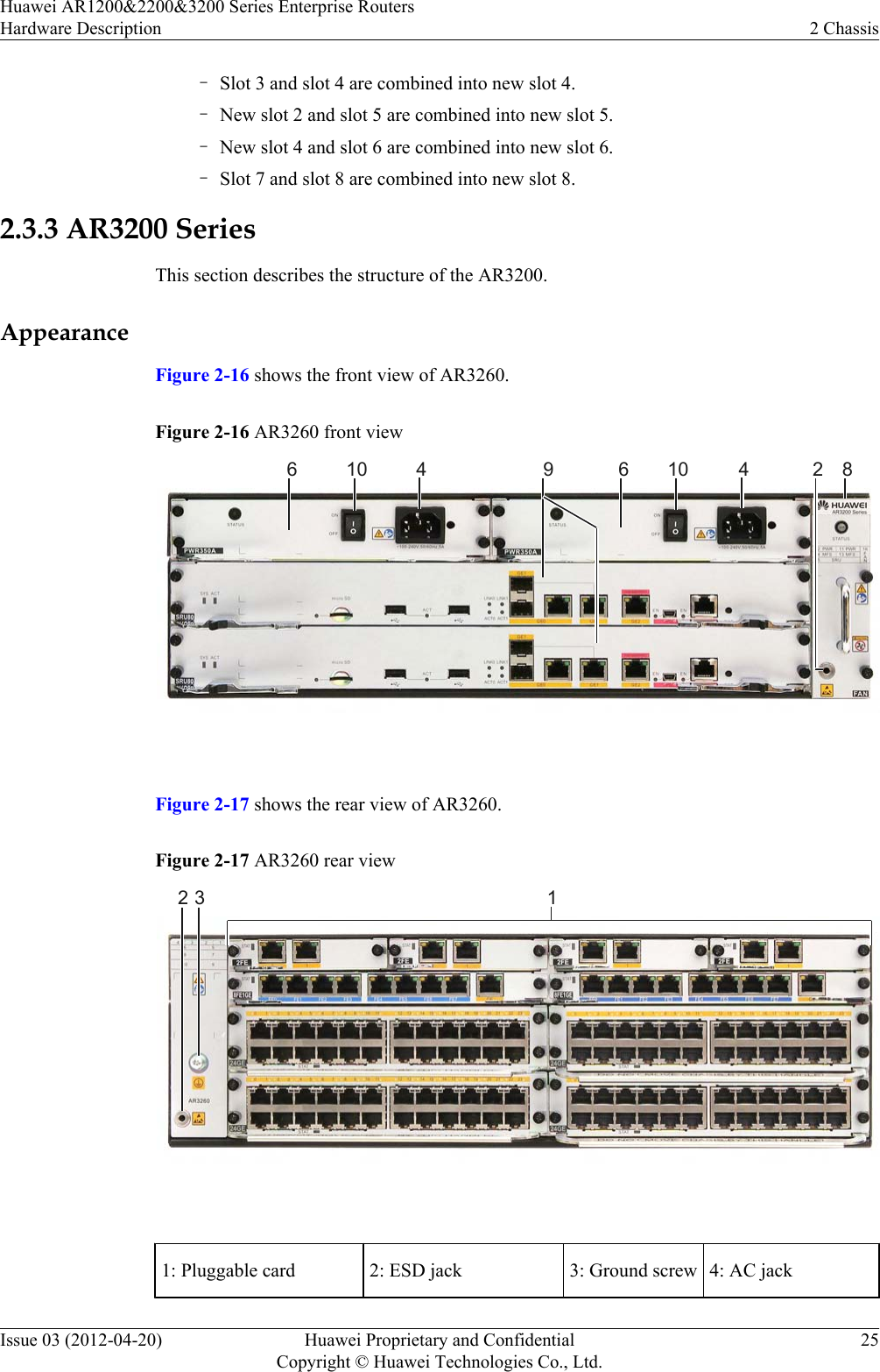
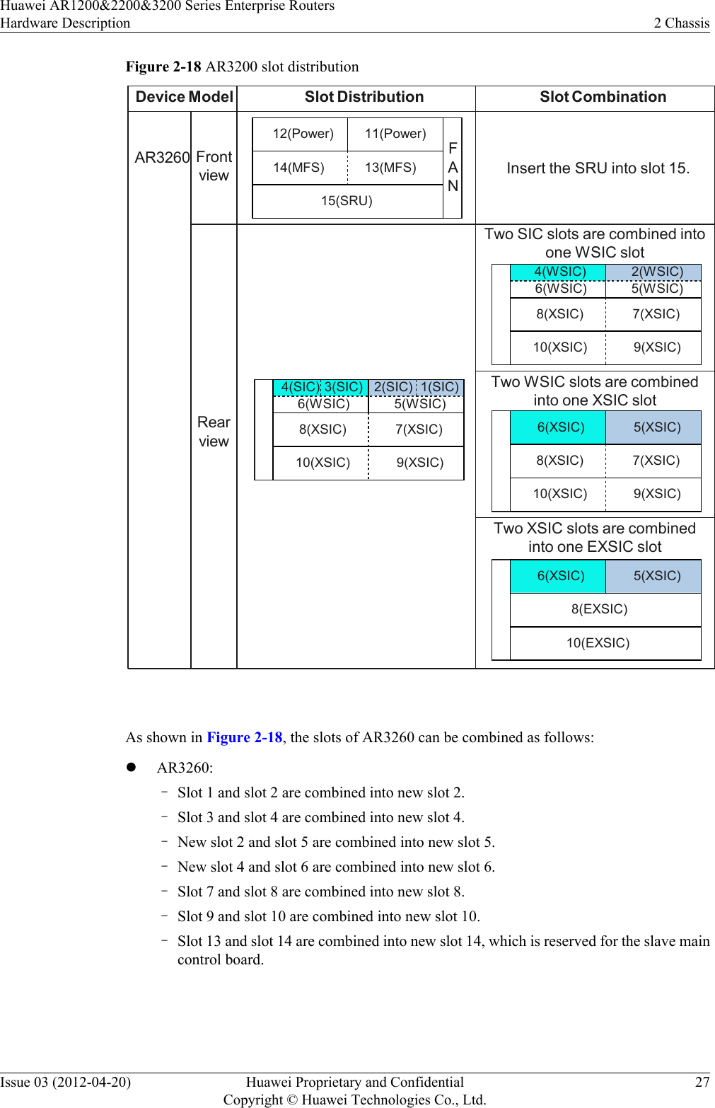
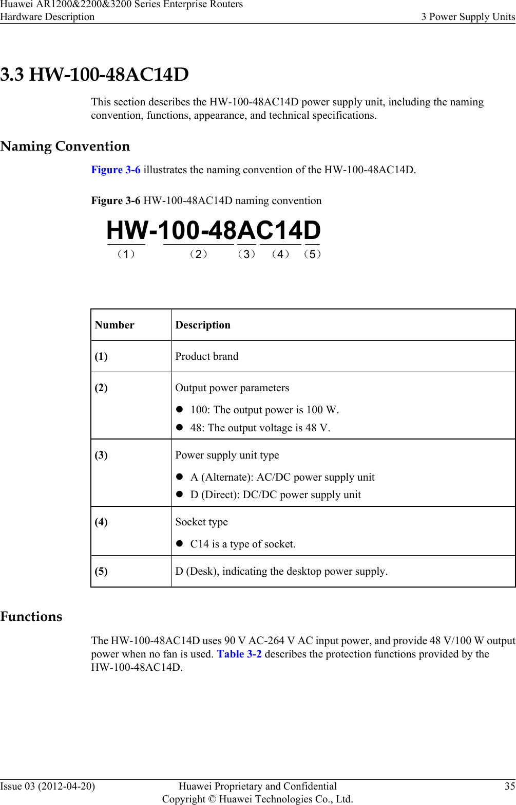
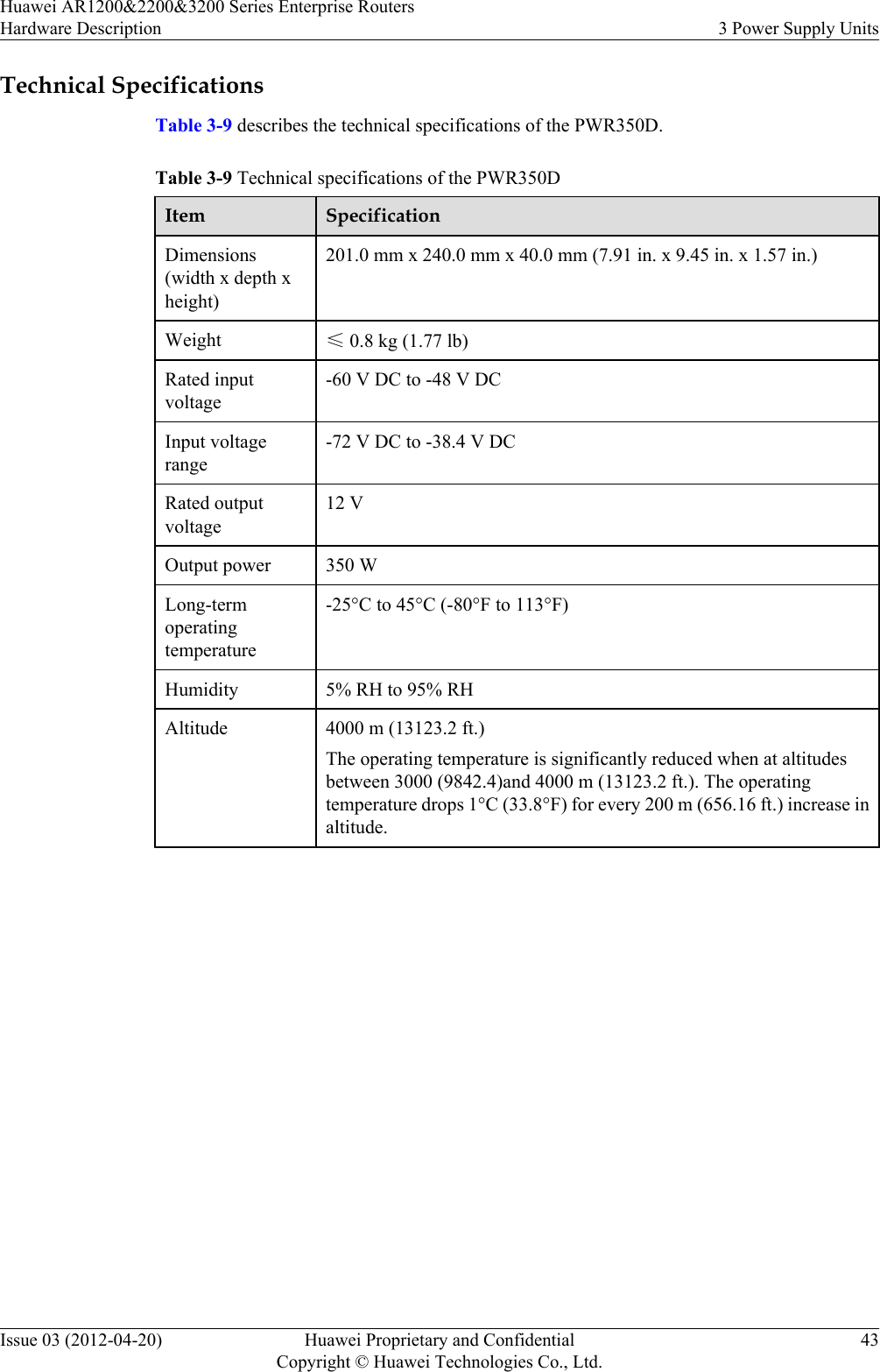
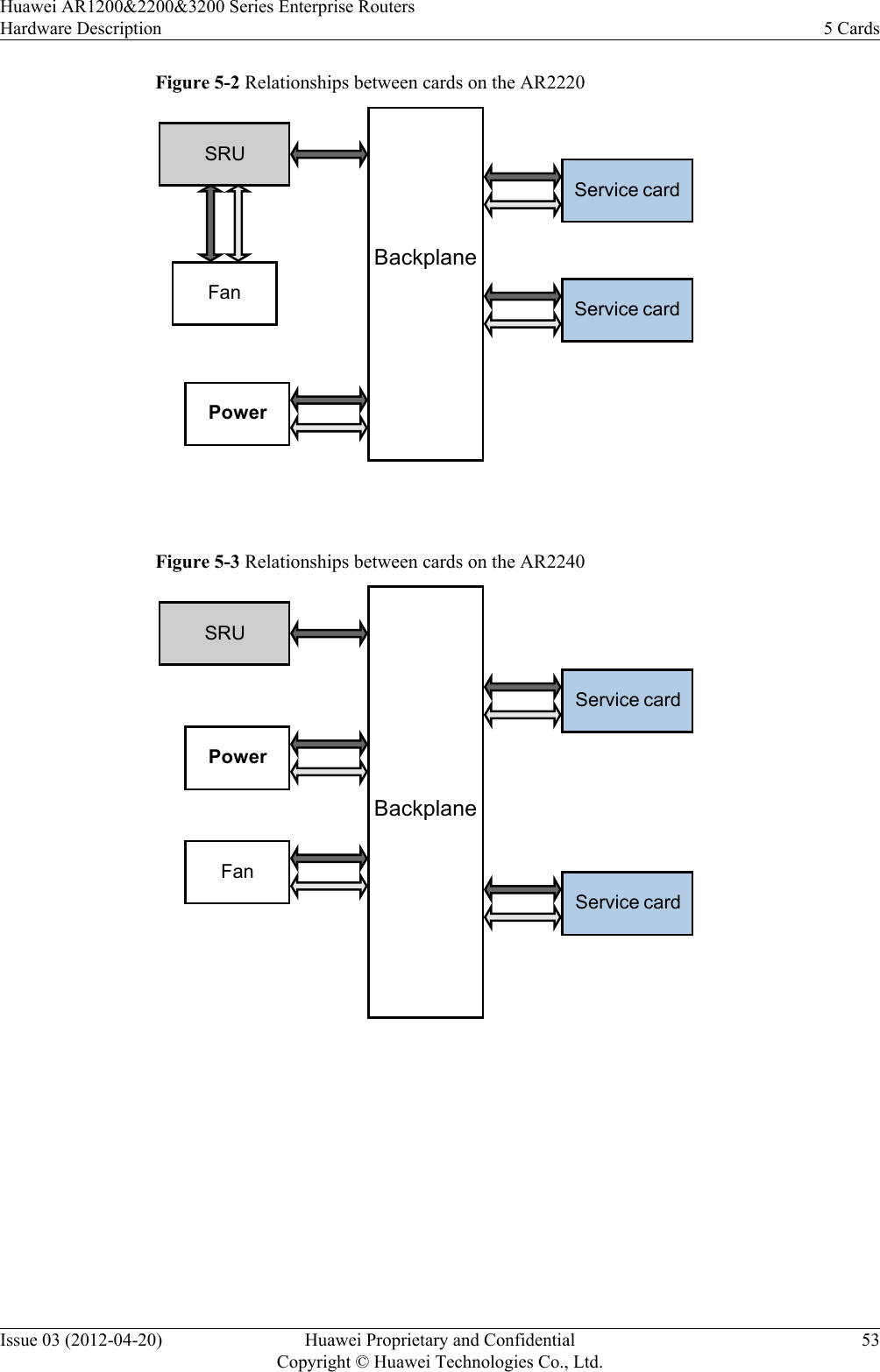
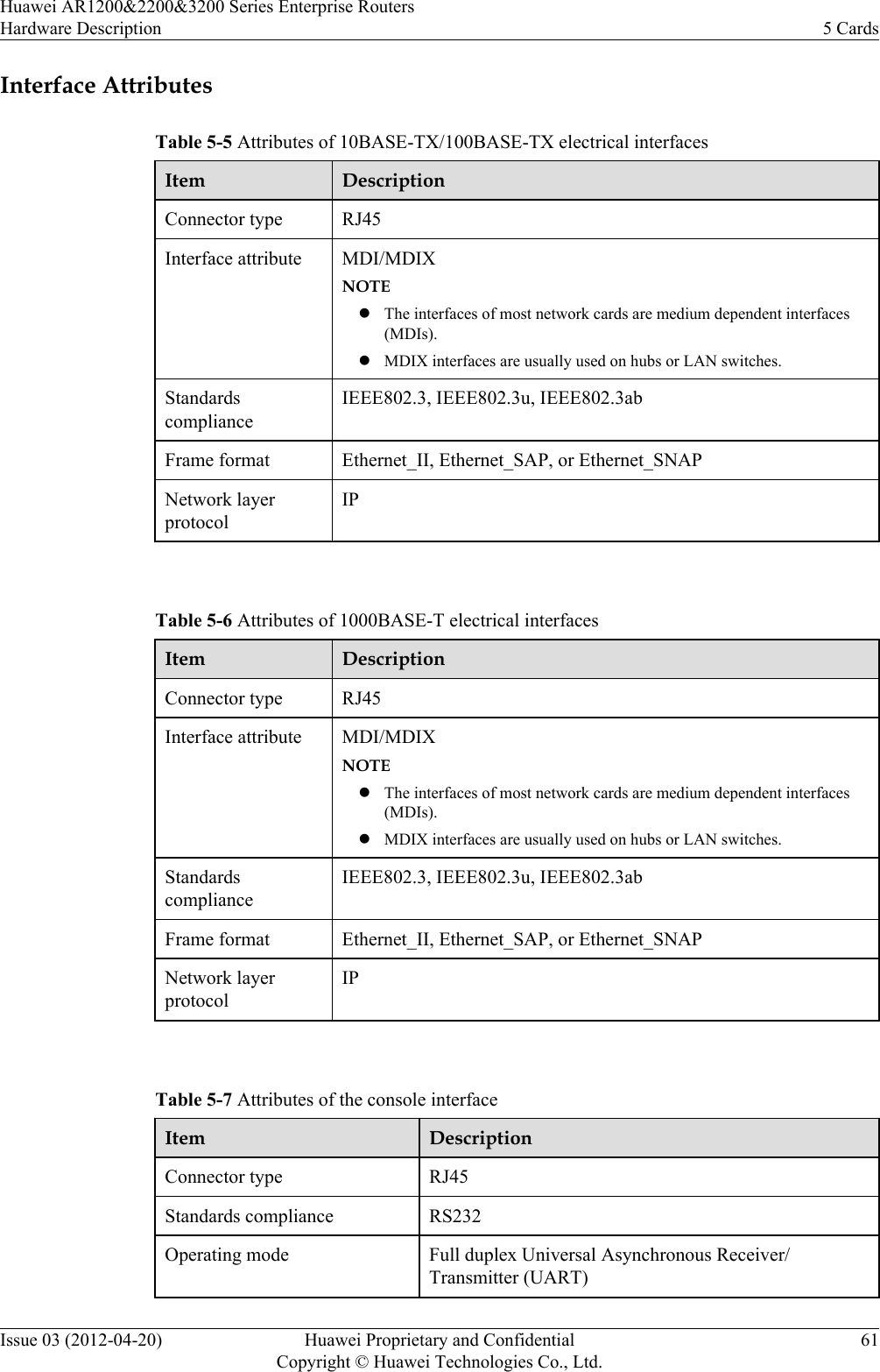
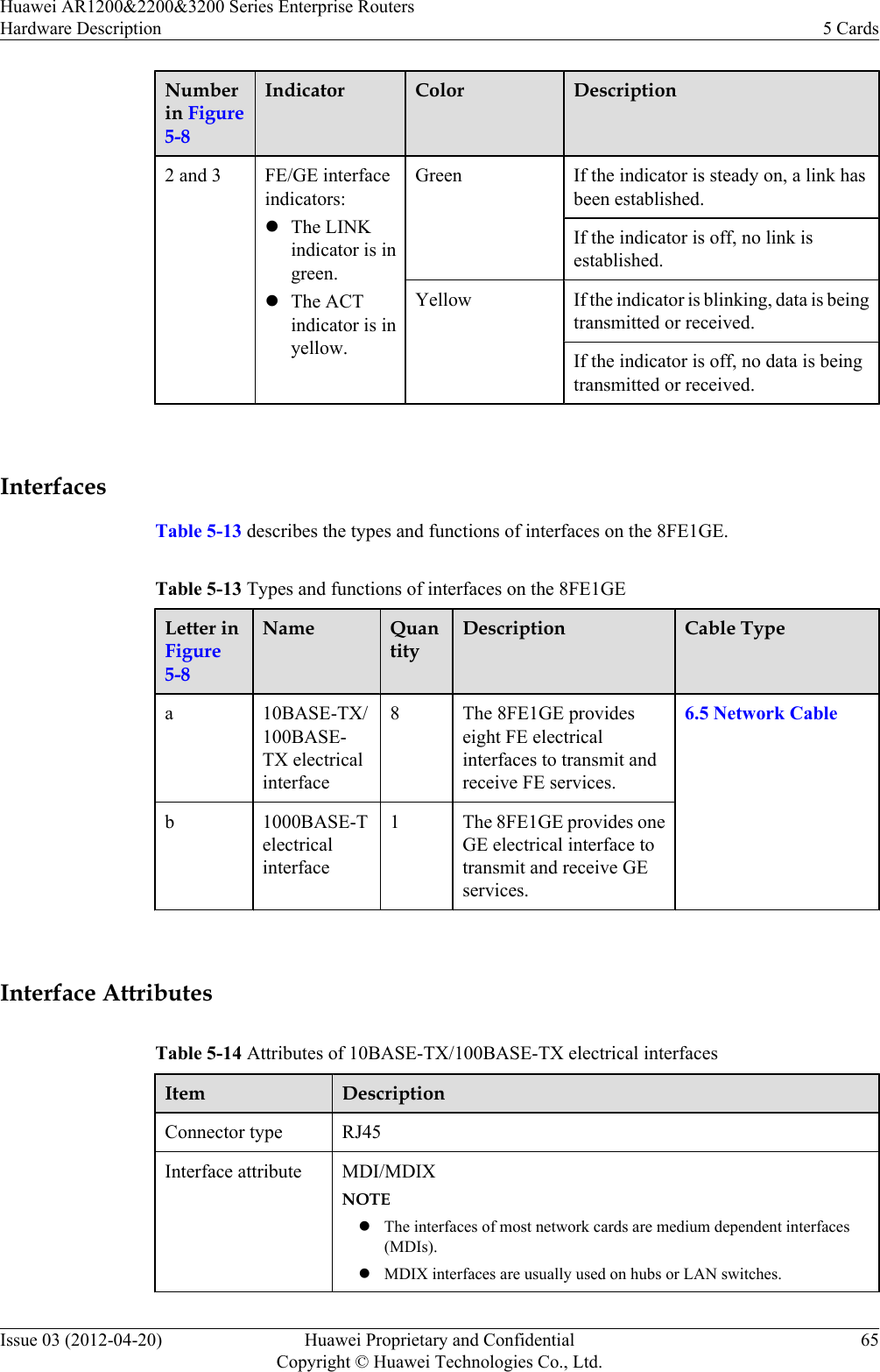
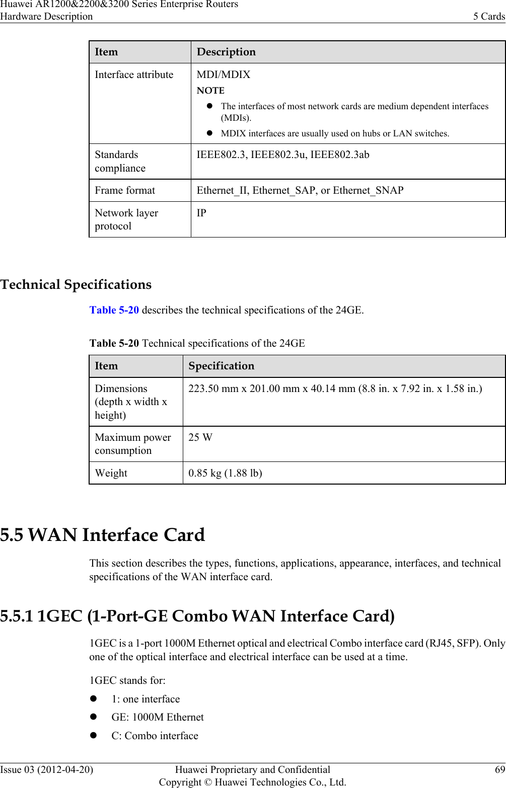
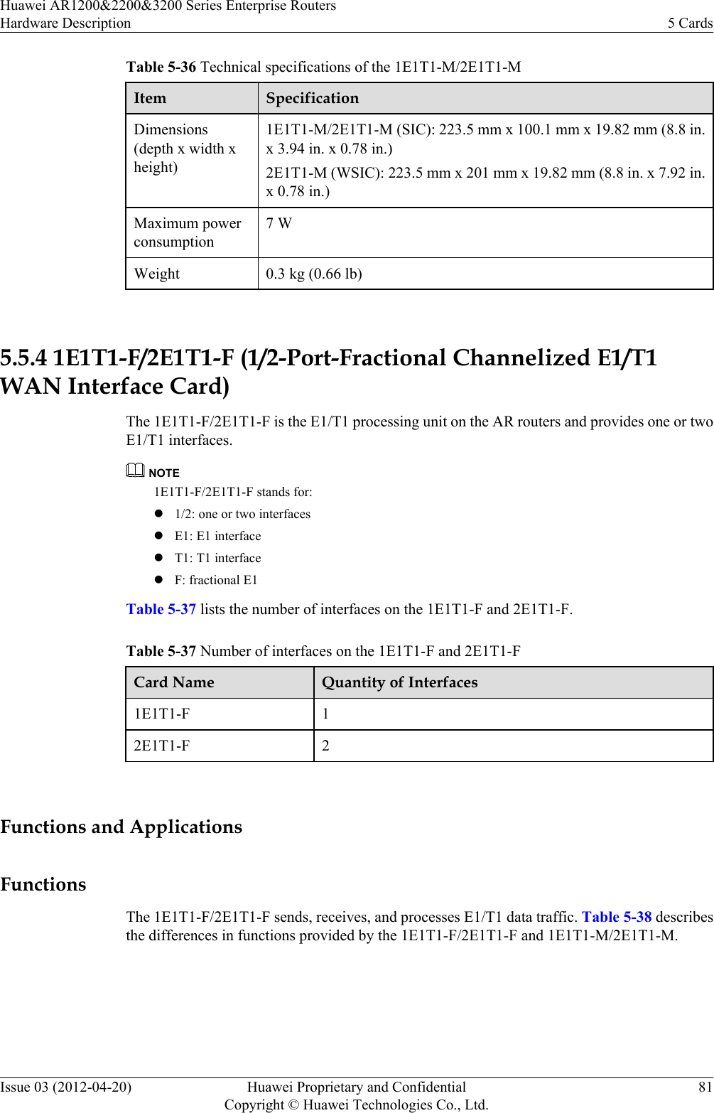
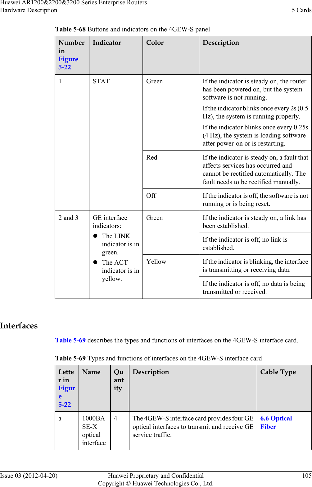
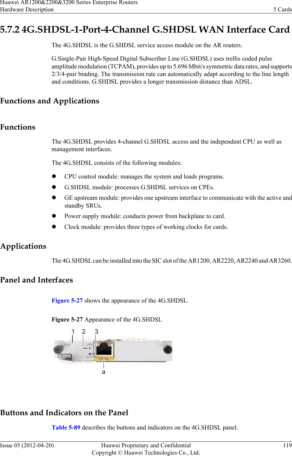
![Model CharacteristicsAR2200 AR2220 The AR2220 is 1 U high (1 U = 44.45 mm), uses a 150 W powersupply unit, and supports four SIC cards and two WSIC cards. Theintegrated SRU supports fixed 3GE interfaces (including one combointerface). The backplane is in the middle of the chassis, and cardsare installed on the front and rear sides of the backplane.AR2240 The AR2240 is 2 U high (1 U = 44.45 mm [1.75 in.]) and uses a 350W pluggable power supply unit. The AR2240 has a backplane, frontsubcards, and rear subcards. The pluggable fan module uses front-access design. The AR2240 supports four SIC cards, two WSIC cards,and two XSIC cards.AR3200 AR3260 The AR3260 is 3 U high (1 U = 44.45 mm [1.75 in.]) and uses a 350W pluggable power supply unit. The AR3260 has a backplane, frontsubcards, and rear subcards. The pluggable fan module uses front-access design. The AR3260 supports four SIC cards, two WSIC cards,and four XSIC cards. NOTElSIC: Service Interface Card. This is the smallest card supported by ARs.lWSIC: Wide SIC. The same height as a SIC, but twice the width.lXSIC: Extended SIC. Double the height and width of an XSIC and twice those of a SIC.lEXSIC: Extra-Extended SIC. Twice the height of a SIC, and four times the width of a SIC.NOTEIn this document, AR1200 indicates AR1220, AR1220V, AR1220W, and AR1220VW.2.2 Naming ConventionThis section describes the naming conventions used when naming AR routers.Figure 2-1 Naming convention【AR】【B1 B2 B3 B4】【C1】【-D1】Example:AR1220 V Huawei AR1200&2200&3200 Series Enterprise RoutersHardware Description 2 ChassisIssue 03 (2012-04-20) Huawei Proprietary and ConfidentialCopyright © Huawei Technologies Co., Ltd.17](https://usermanual.wiki/Huawei-Technologies/AR1220WIFI.User-manual-III/User-Guide-1716095-Page-24.png)
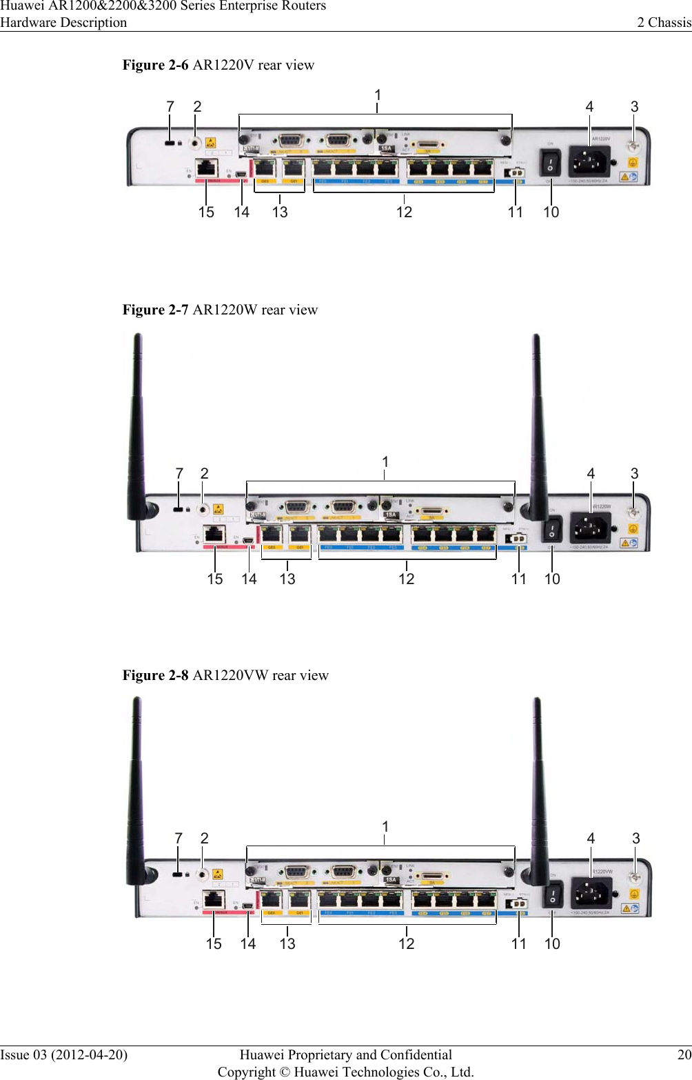
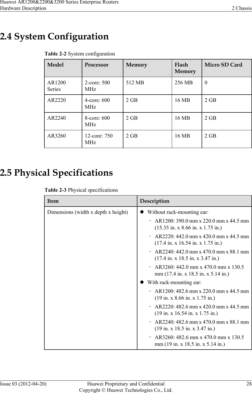
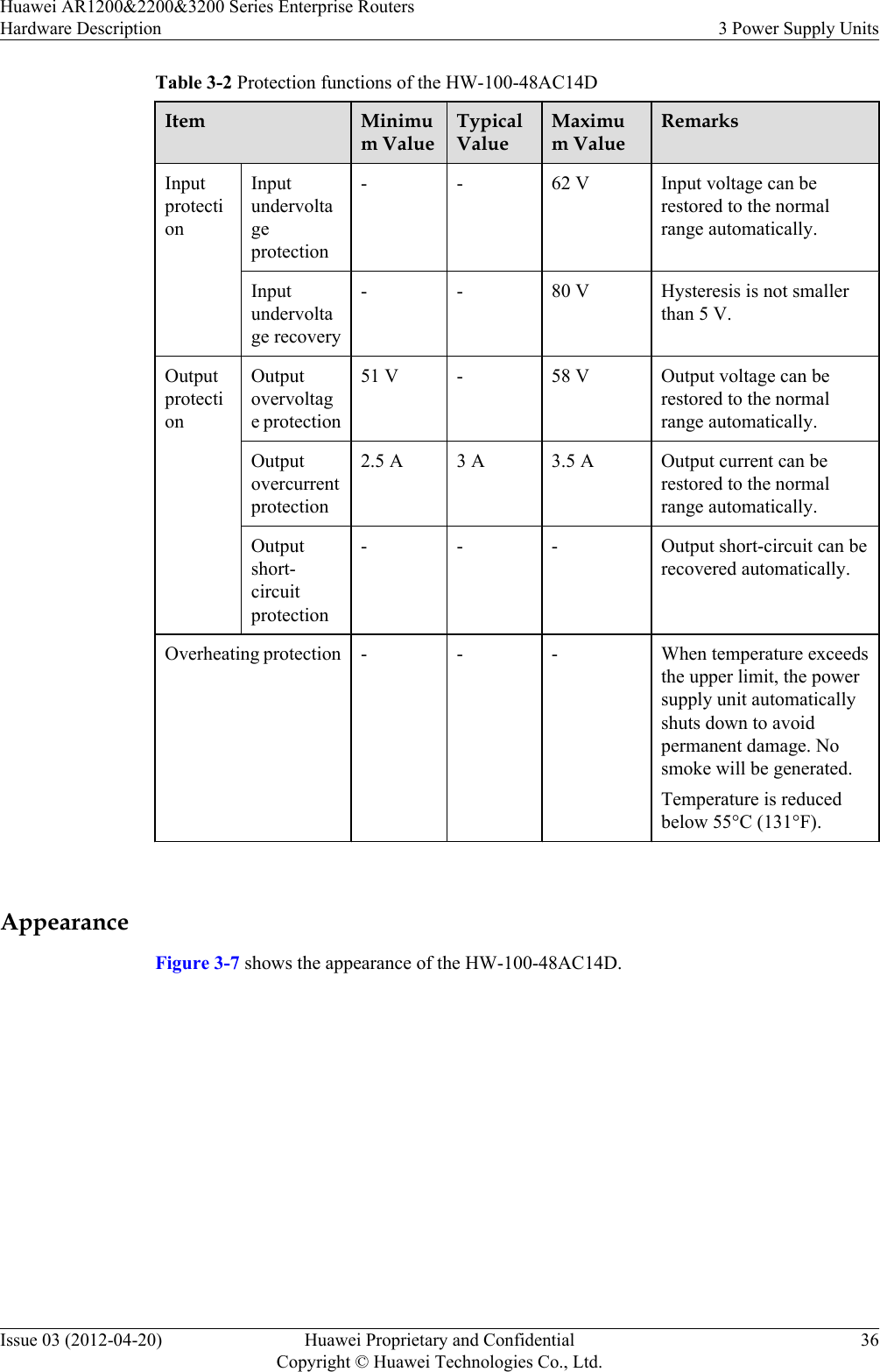
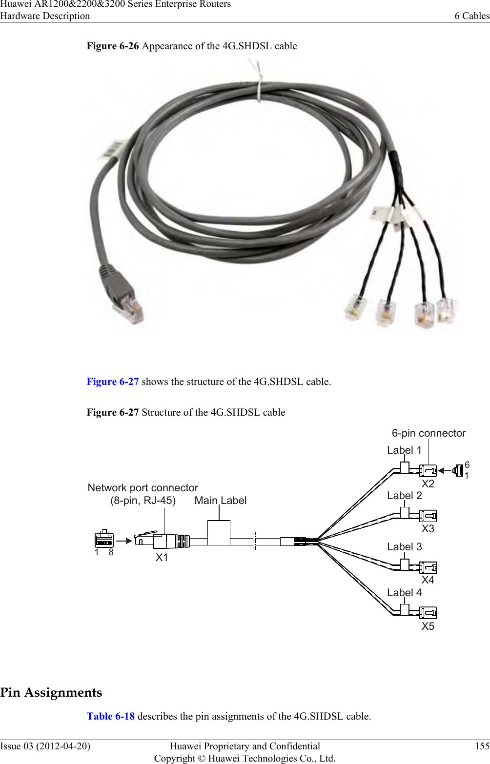
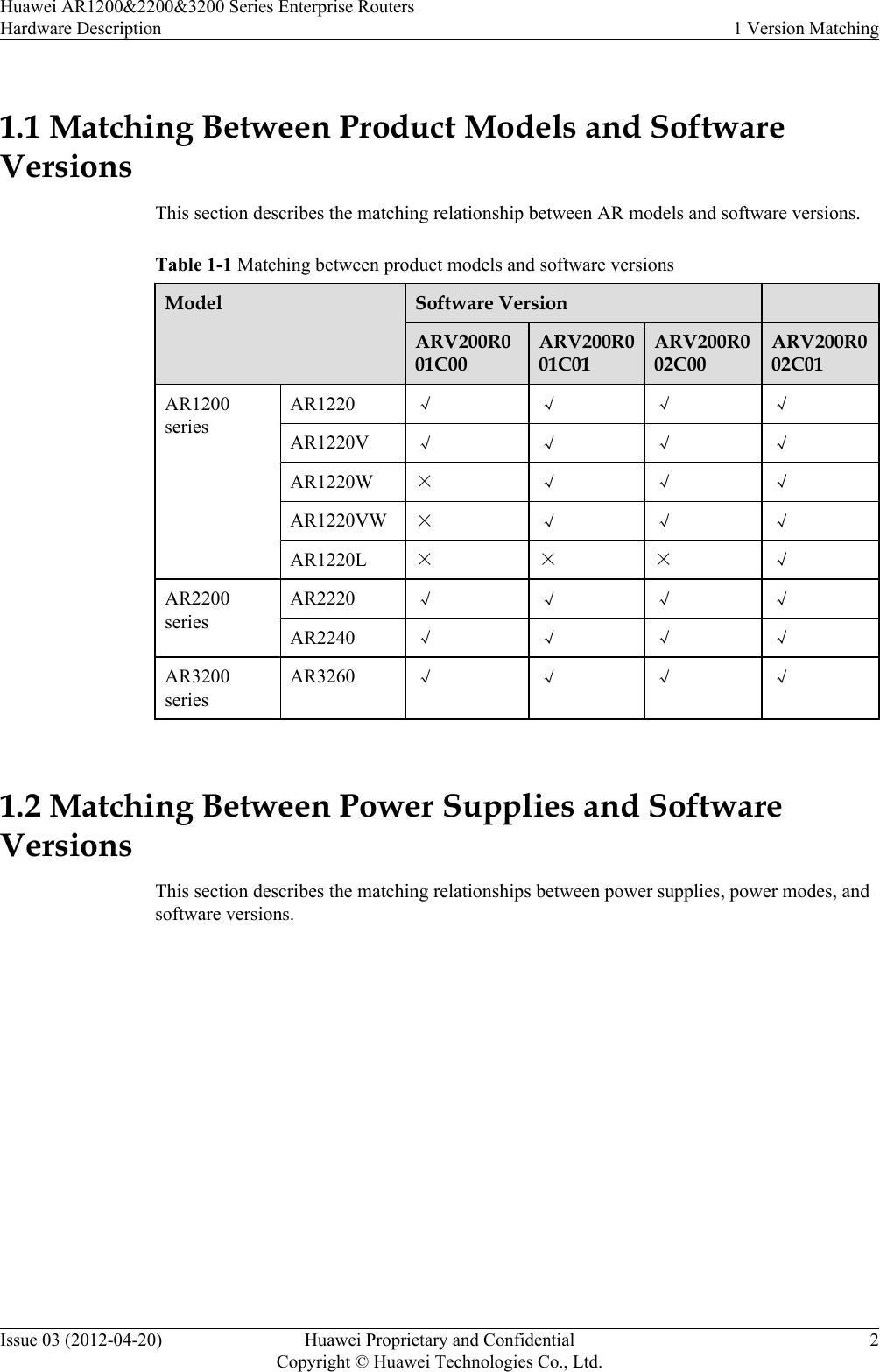
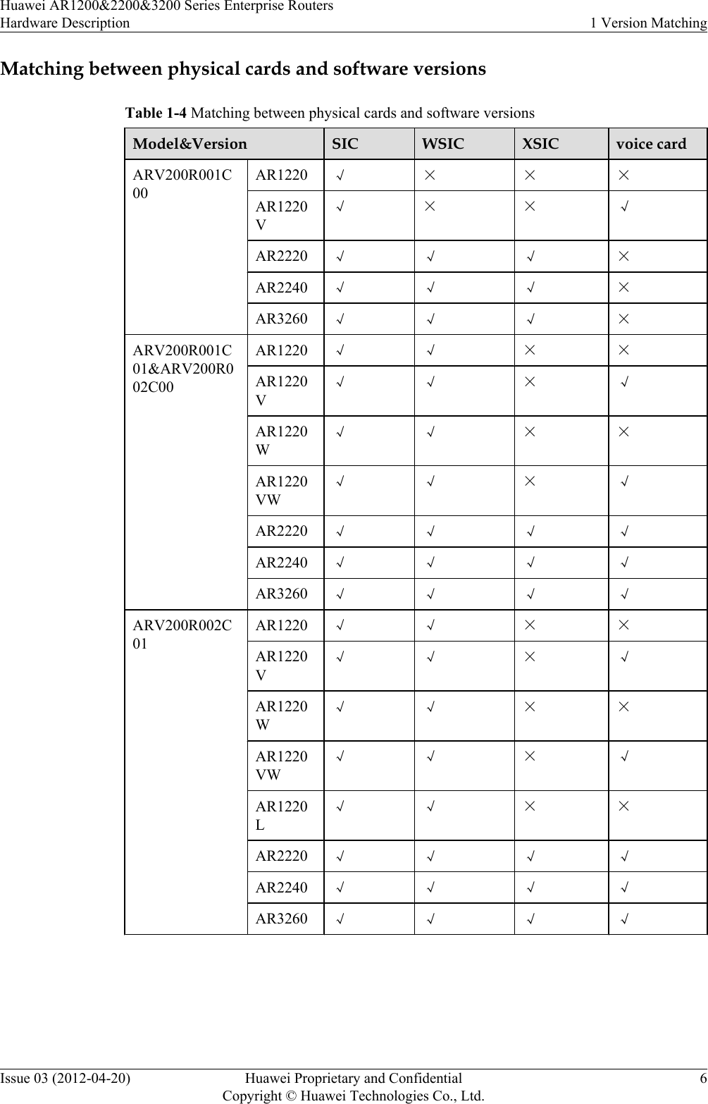
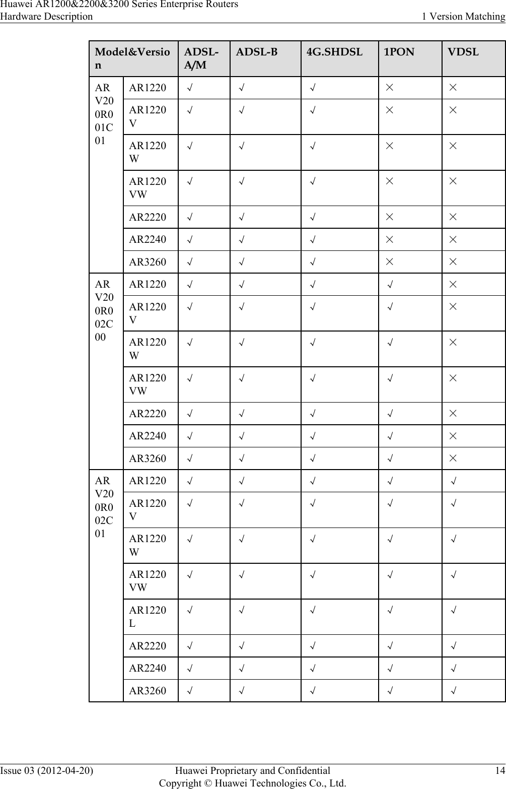
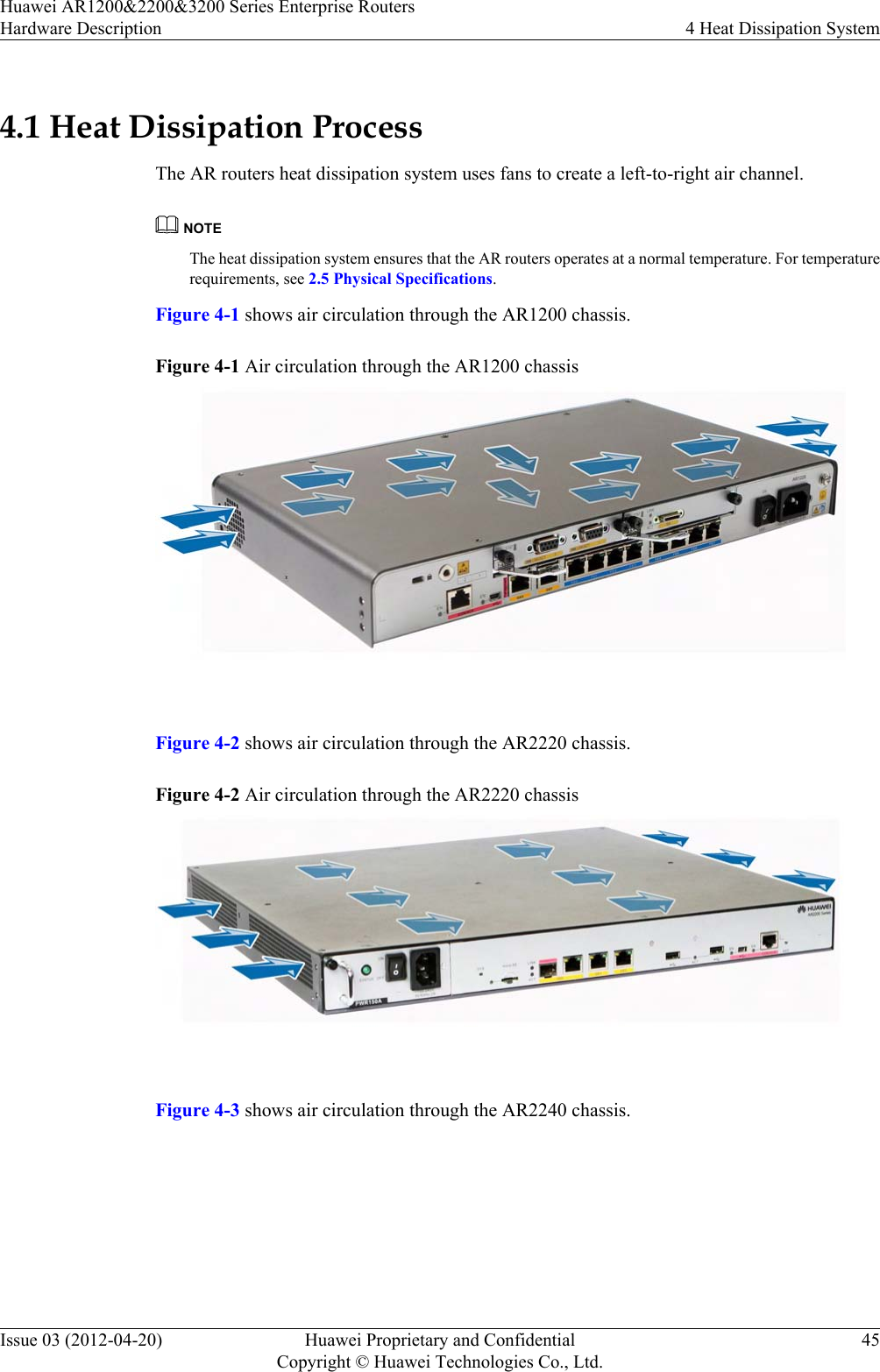
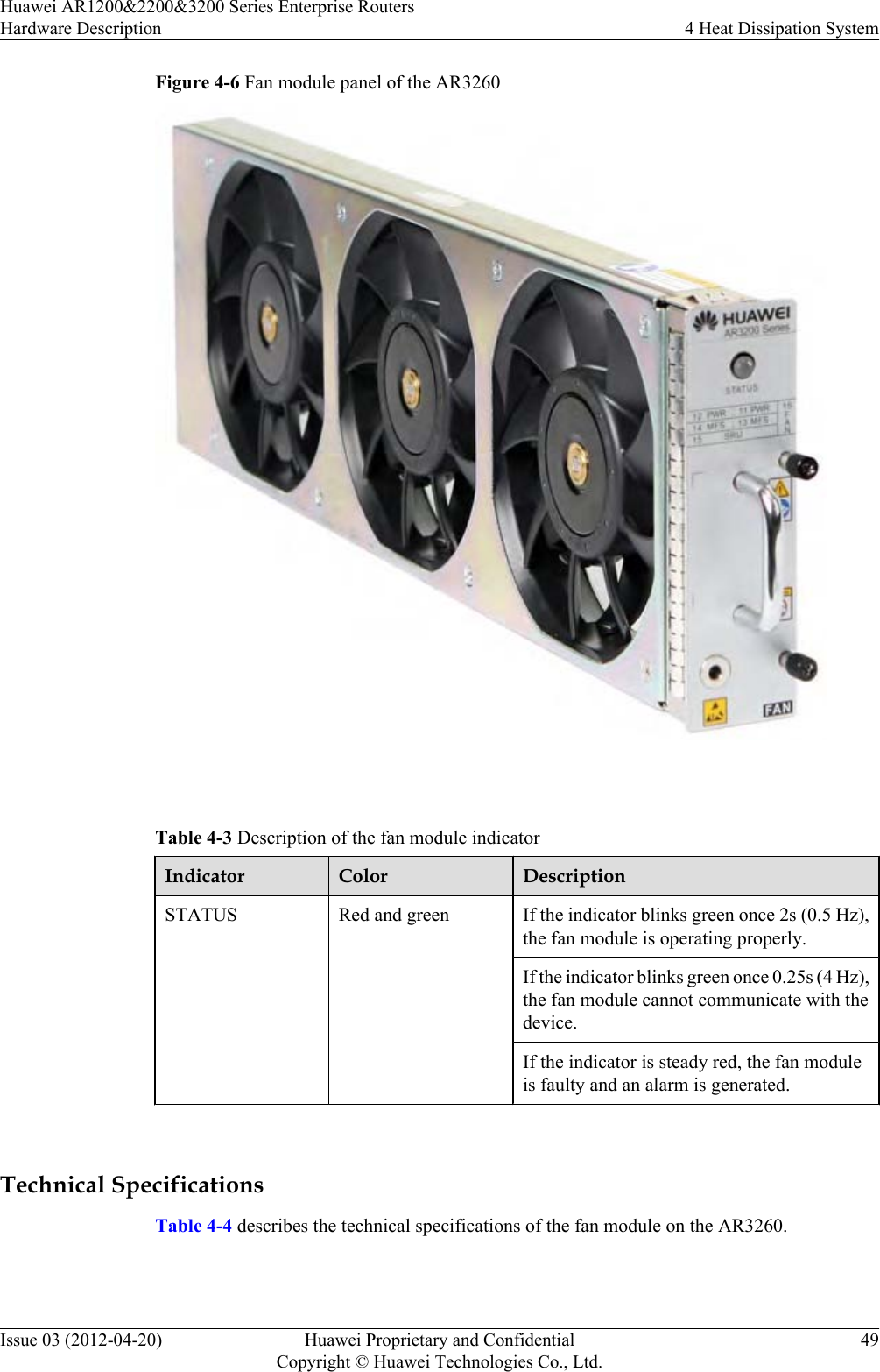
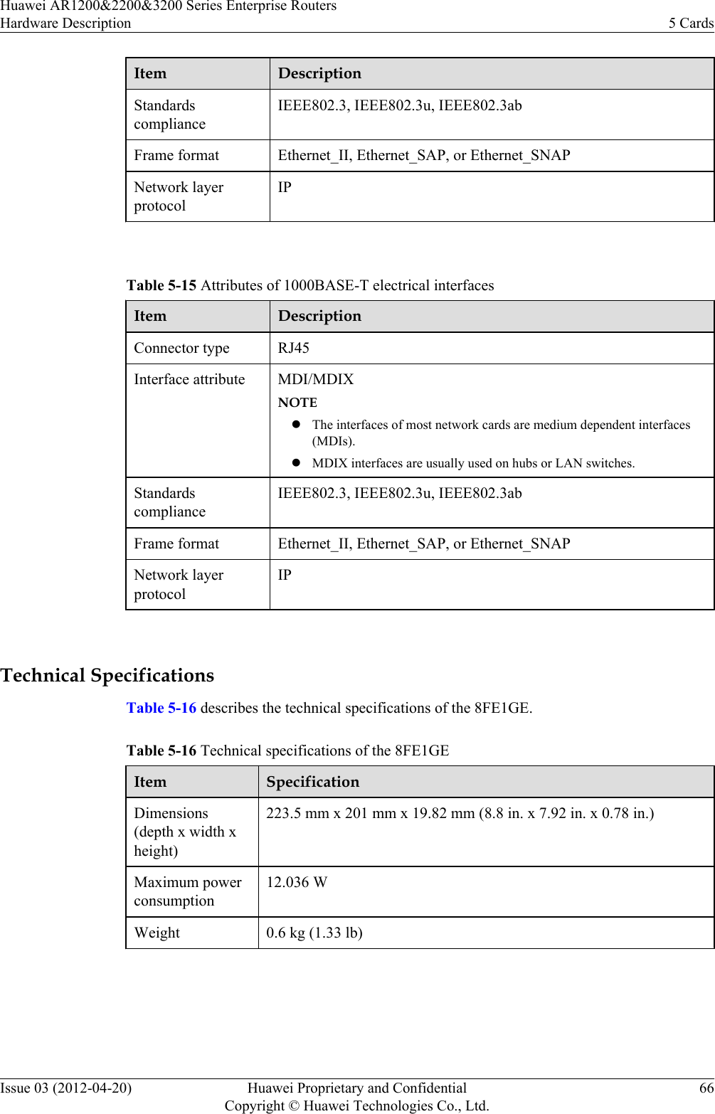
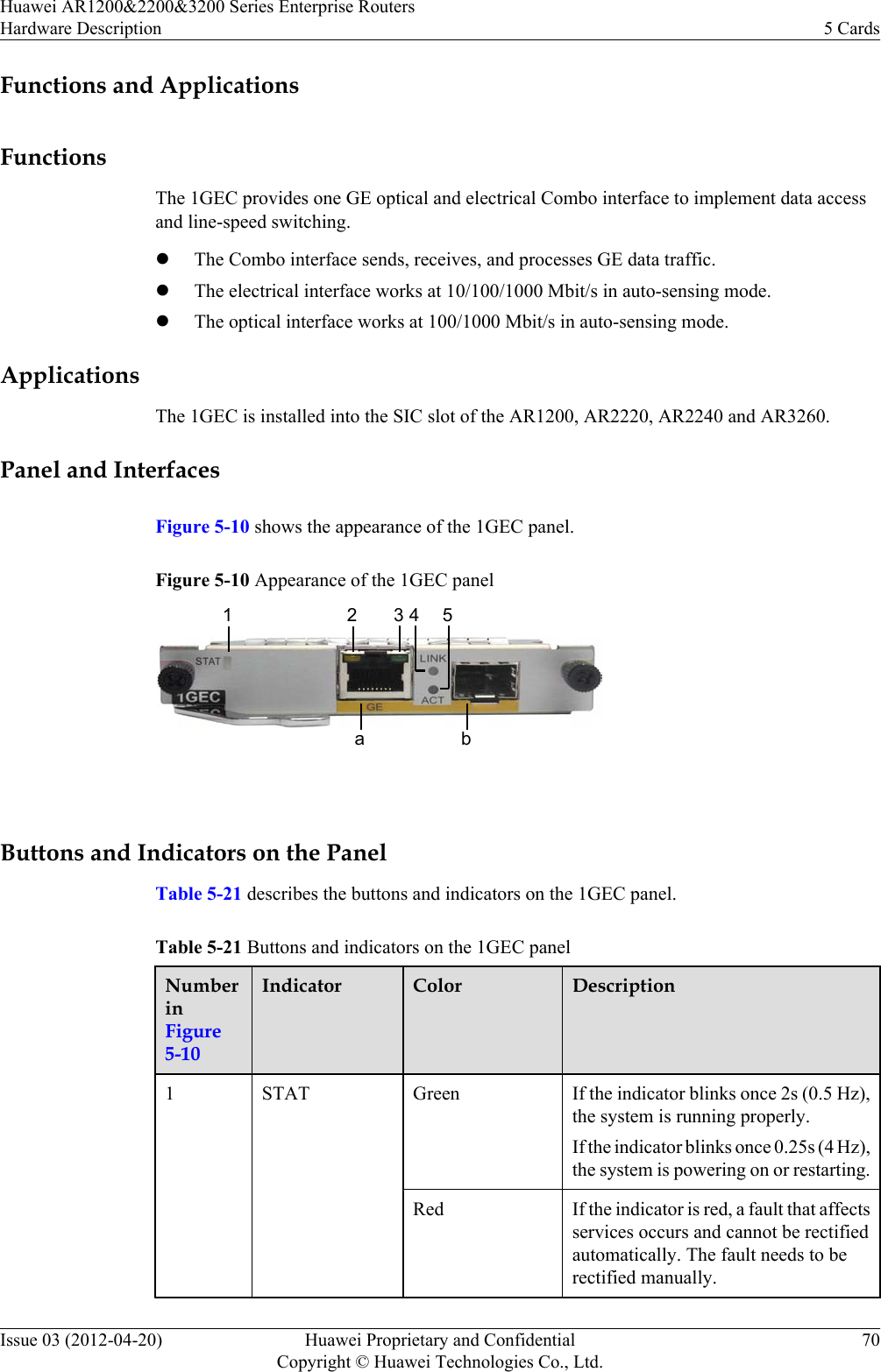
![4 Heat Dissipation SystemAbout This ChapterThis section describes the heat dissipation system of the AR router.The fan module of the AR router is described as follows:lThe fan module of the AR1200 and AR2220 is located on the right side in the chassis.–The fan module dimensions of the AR1200 are 40 mm [1.58 in.] (width) x 20 mm [0.79in.] (depth).–The fan module dimensions of the AR2220 are 40 mm [1.58 in.] (width) x 20 mm [0.79in.] (depth).lThe fan module of the AR2240 is 2 U high. It is pluggable and uses front-access design.lThe fan module of the AR3260 is 3 U high. It is pluggable and uses front-access design.4.1 Heat Dissipation ProcessThe AR routers heat dissipation system uses fans to create a left-to-right air channel.4.2 AR2240 Fan ModuleThe AR2240 fan module is 2 U high, pluggable and uses front-access design.4.3 AR3260 Fan ModuleThe fan module of the AR3260 is 3 U high. It is pluggable and uses front-access design.Huawei AR1200&2200&3200 Series Enterprise RoutersHardware Description 4 Heat Dissipation SystemIssue 03 (2012-04-20) Huawei Proprietary and ConfidentialCopyright © Huawei Technologies Co., Ltd.44](https://usermanual.wiki/Huawei-Technologies/AR1220WIFI.User-manual-III/User-Guide-1716095-Page-51.png)
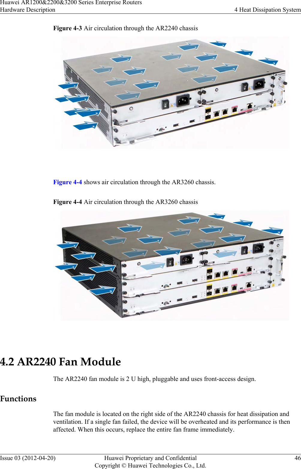
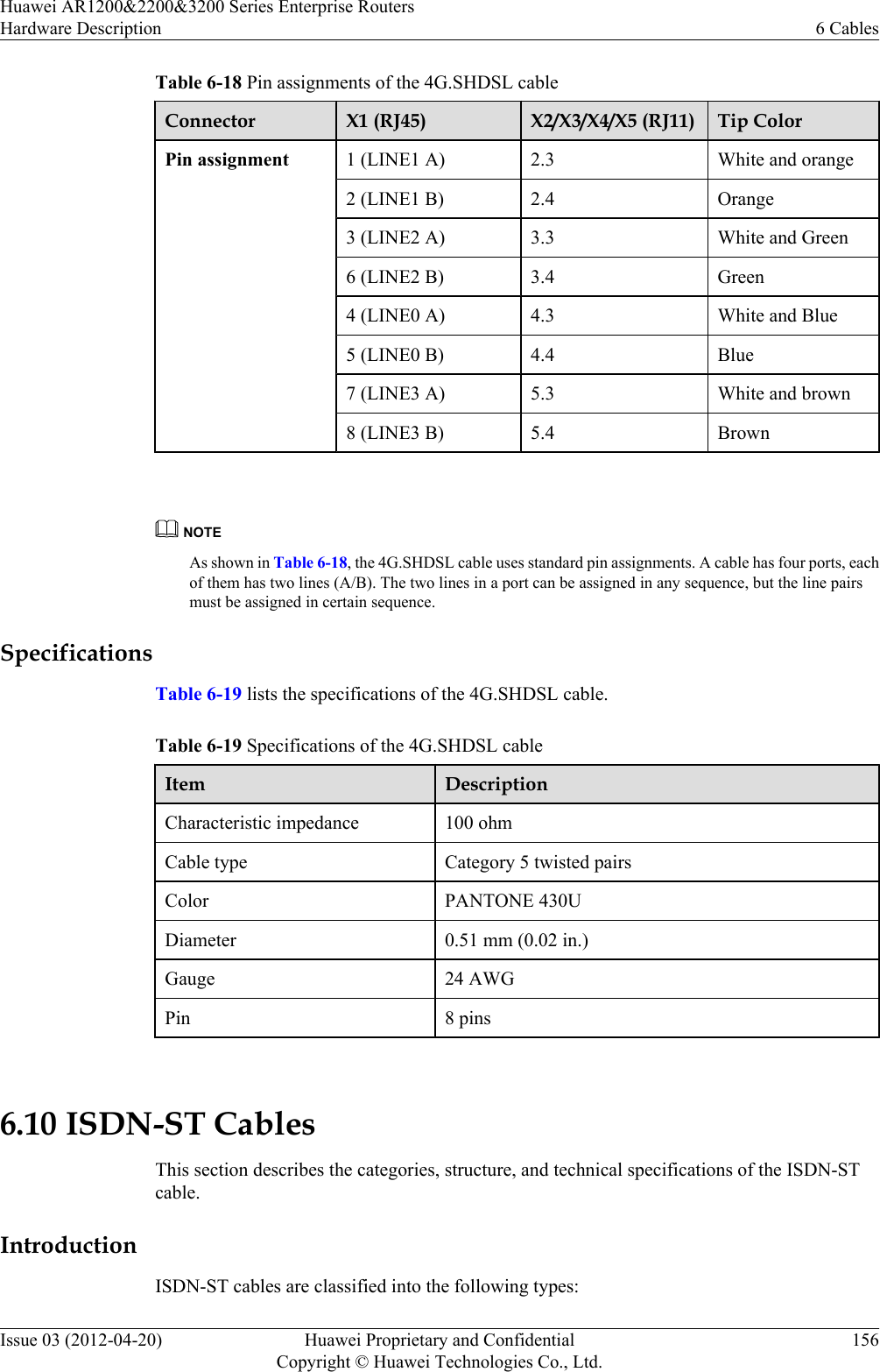
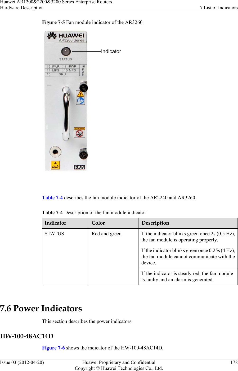
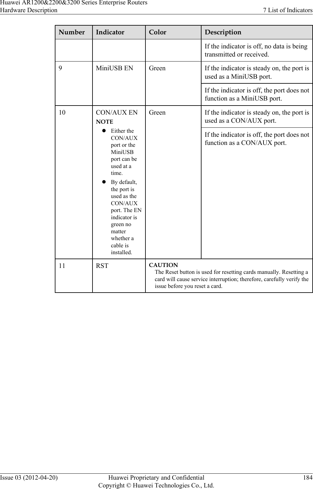
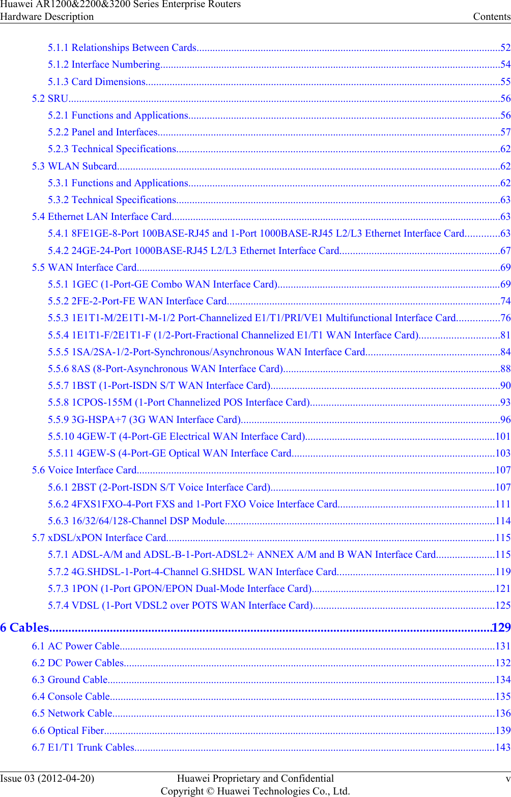
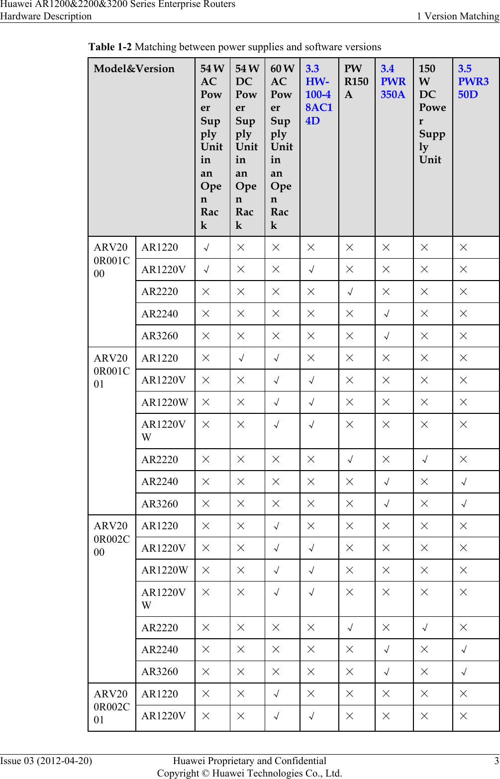
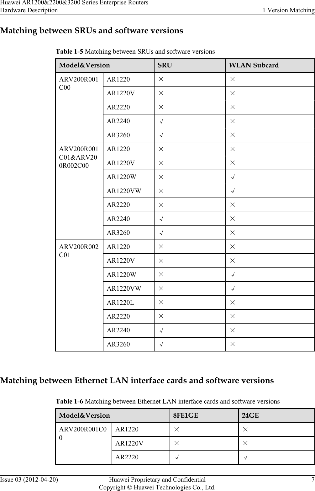
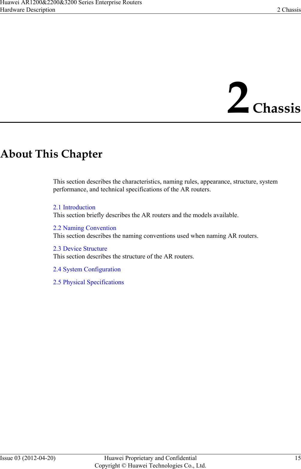
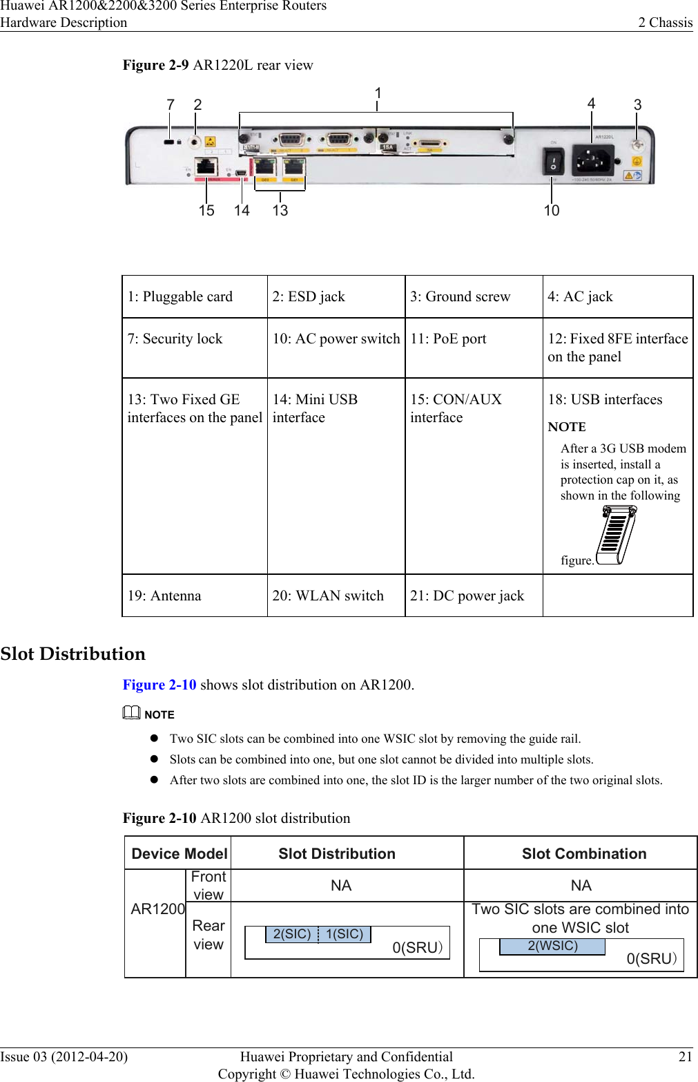
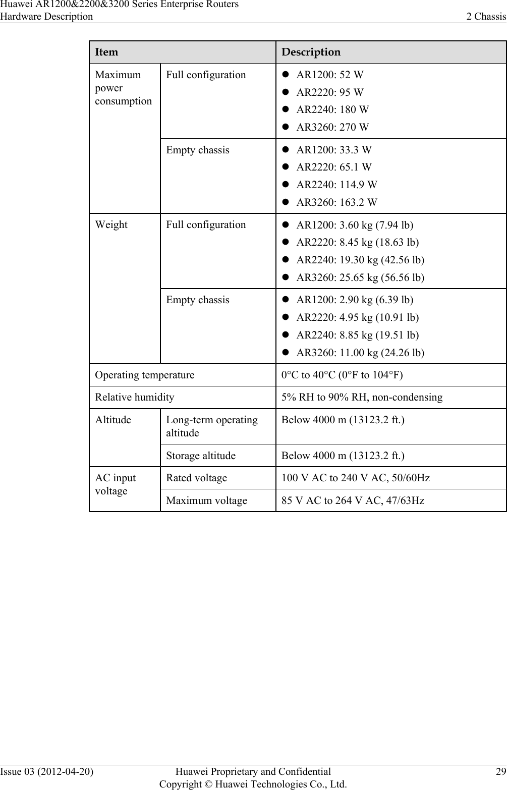
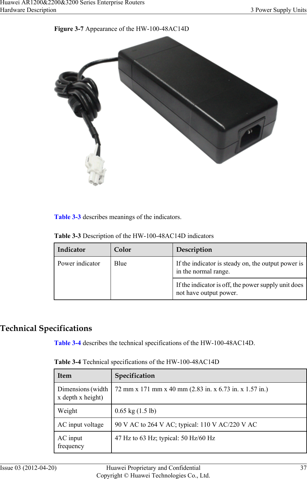
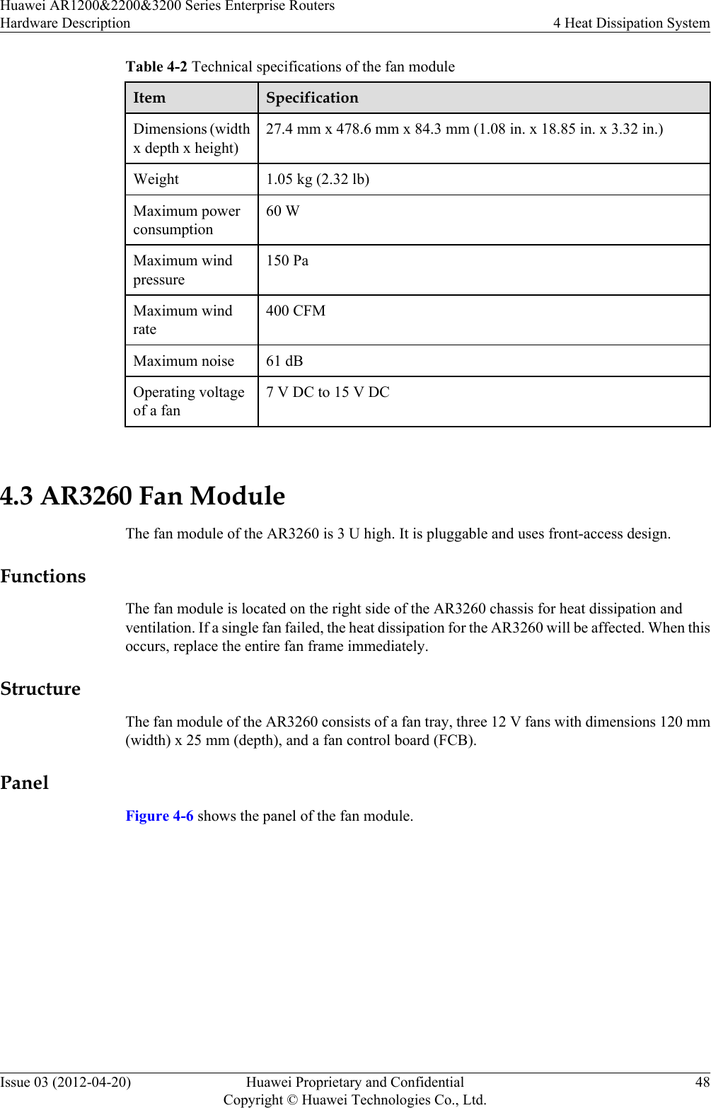
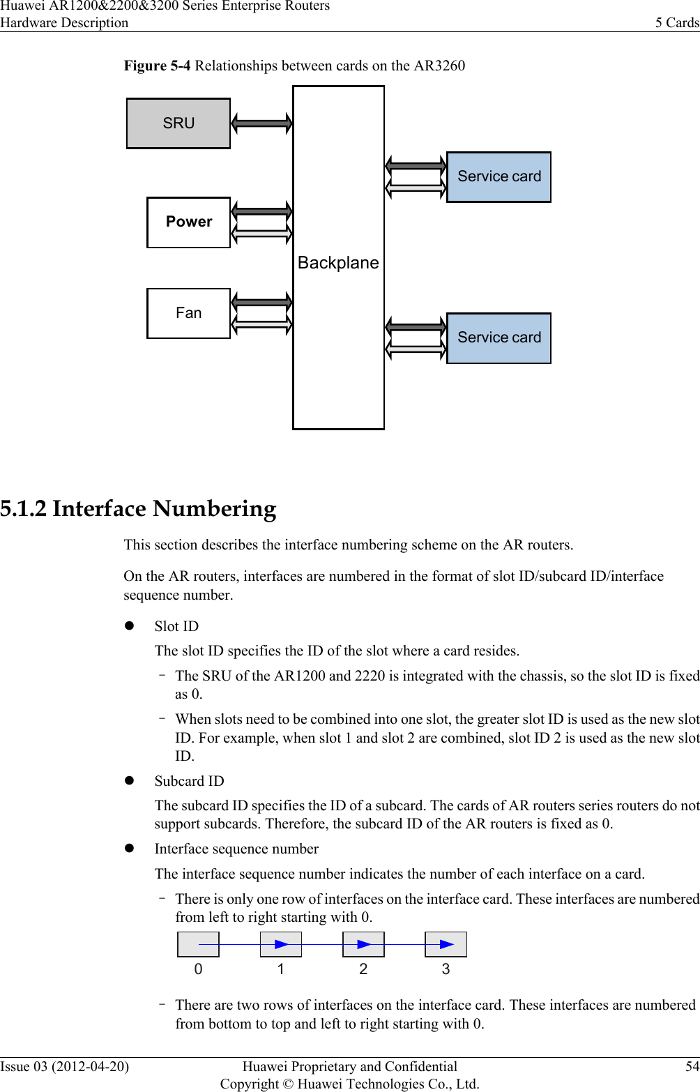
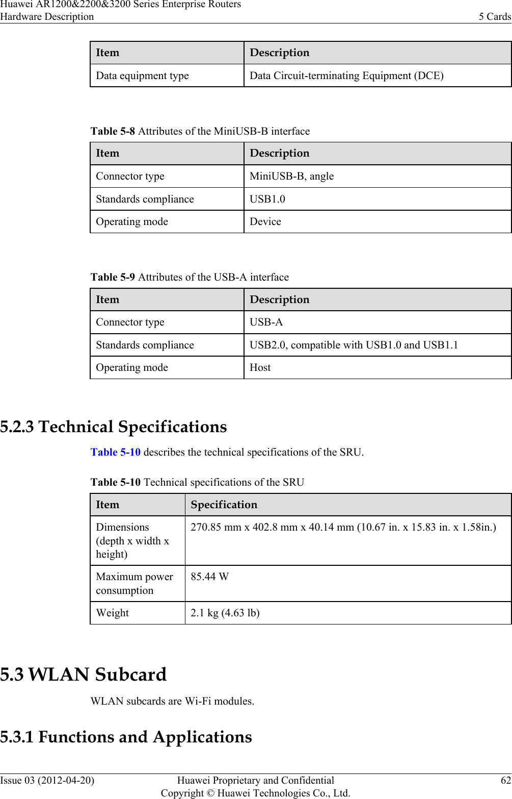
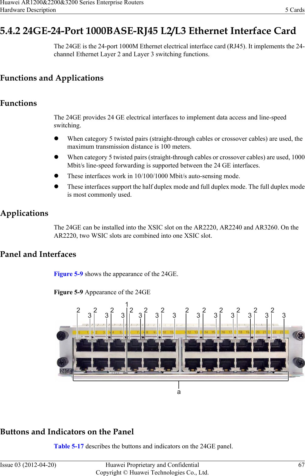
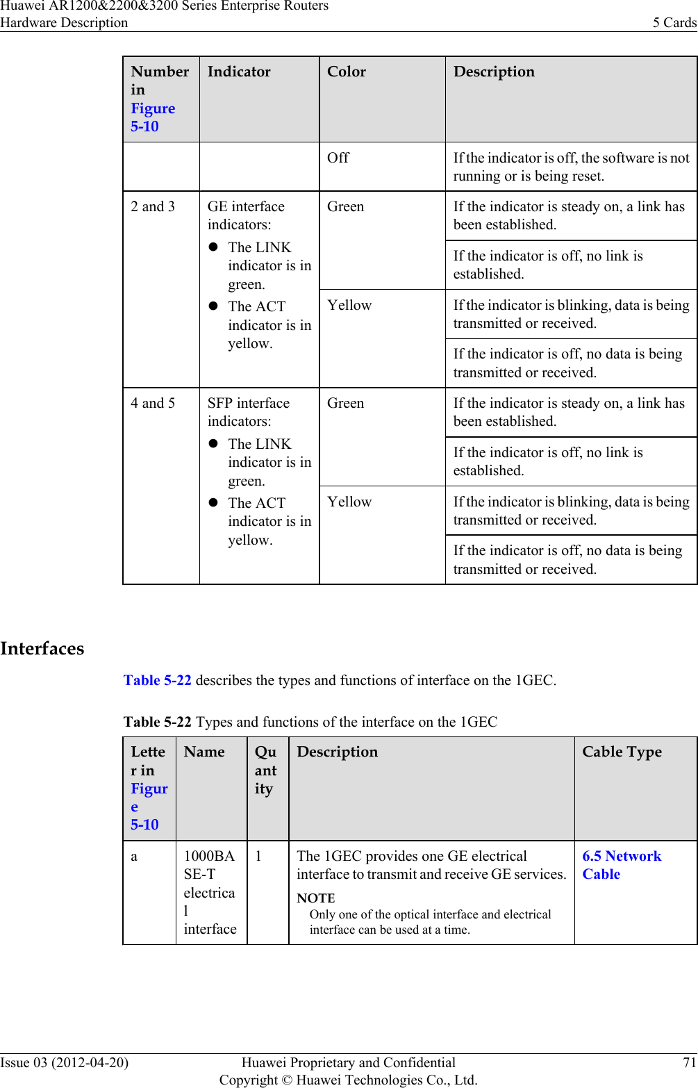
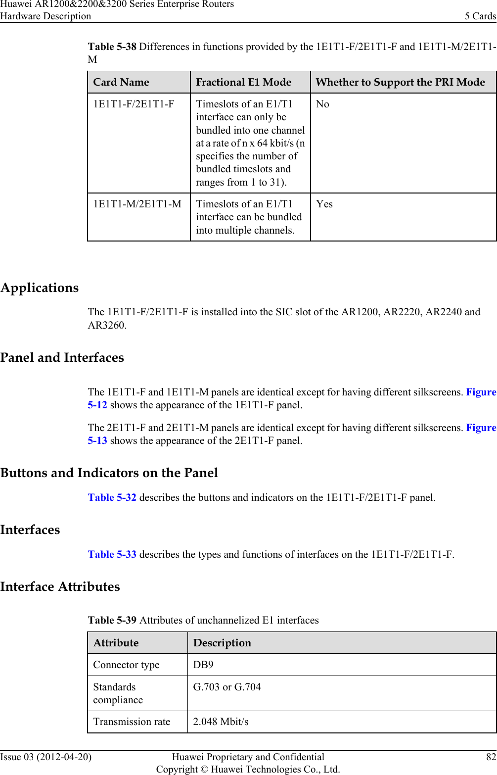
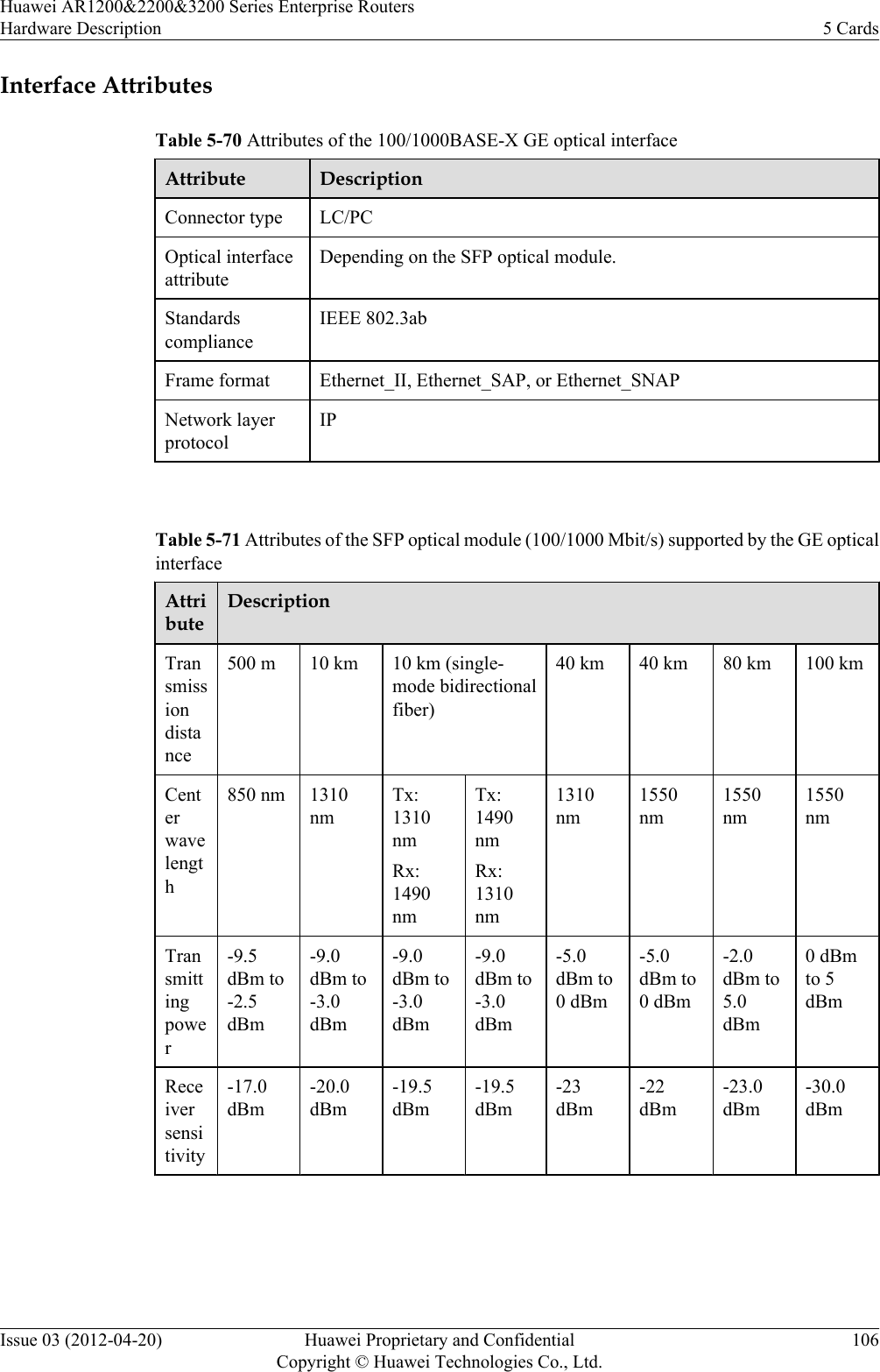
![StructureThe fan module of the AR2240 consists of a fan tray, five 12 V fans with dimensions 80 mm[3.16 in.] (width) x 25 mm [0.99 in.] (depth), and a fan control board (FCB).PanelFigure 4-5 shows the panel of the fan module.Figure 4-5 Fan module panel of the AR2240 Table 4-1 Description of the fan module indicatorIndicator Color DescriptionSTATUS Red and green If the indicator blinks green once 2s (0.5 Hz),the fan module is operating properly.If the indicator blinks green once 0.25s (4 Hz),the fan module cannot communicate with thedevice.If the indicator is steady red, the fan moduleis faulty and an alarm is generated. Technical SpecificationsTable 4-2 describes the technical specifications of the fan module on the AR2240.Huawei AR1200&2200&3200 Series Enterprise RoutersHardware Description 4 Heat Dissipation SystemIssue 03 (2012-04-20) Huawei Proprietary and ConfidentialCopyright © Huawei Technologies Co., Ltd.47](https://usermanual.wiki/Huawei-Technologies/AR1220WIFI.User-manual-III/User-Guide-1716095-Page-54.png)
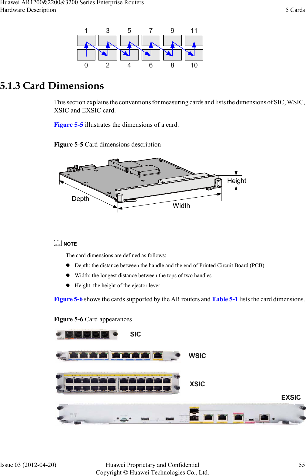
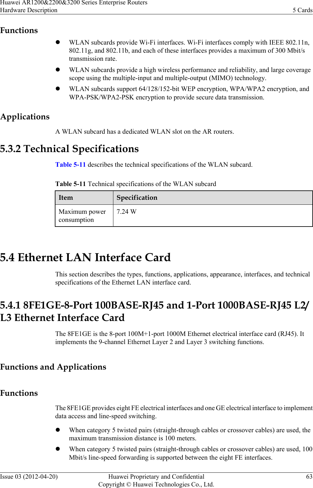
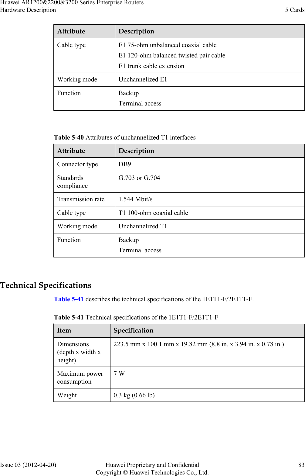
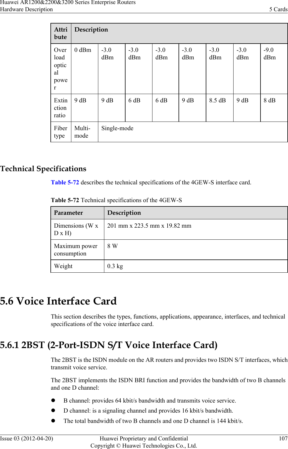
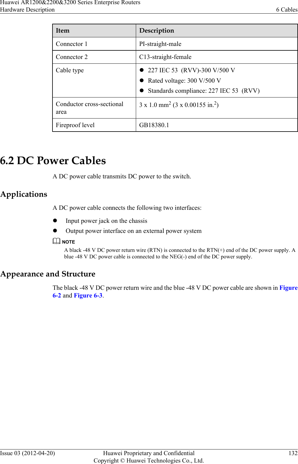
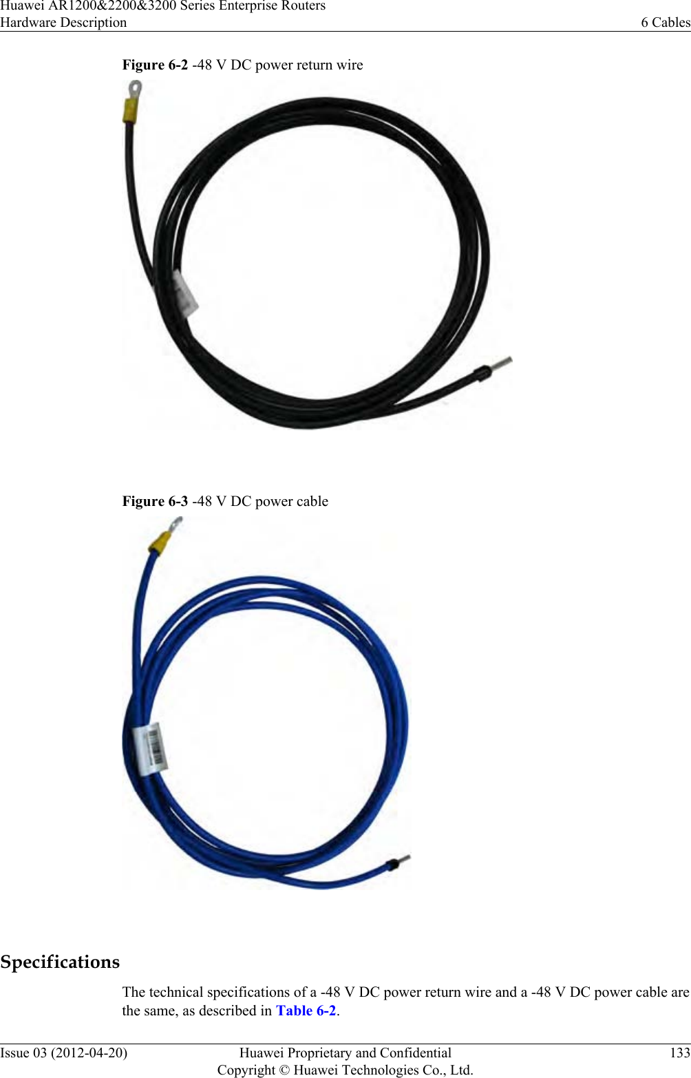
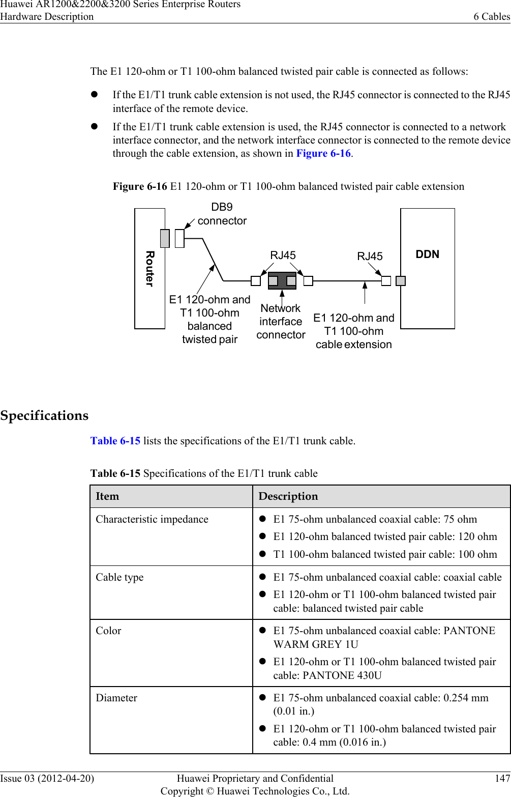
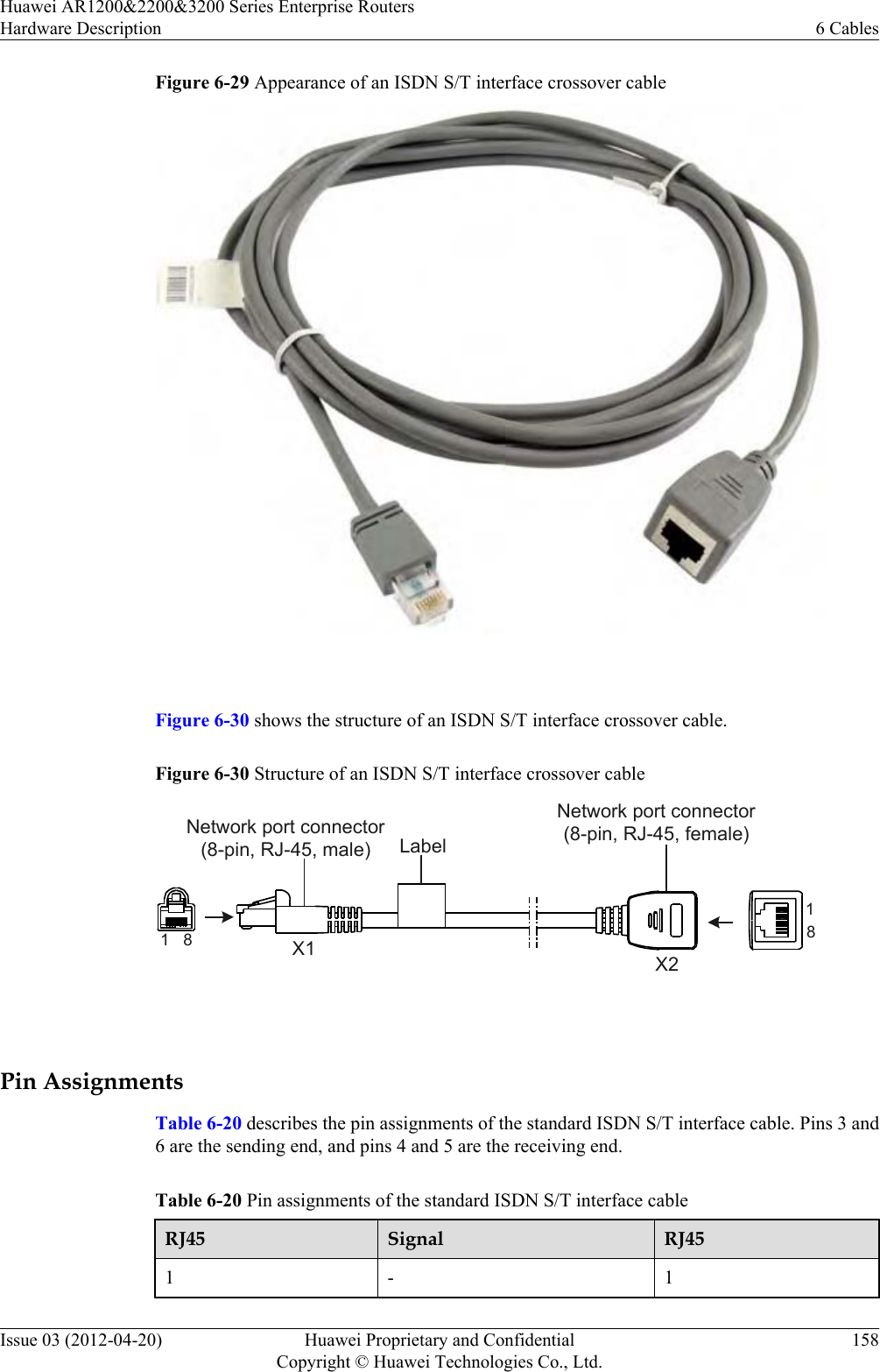
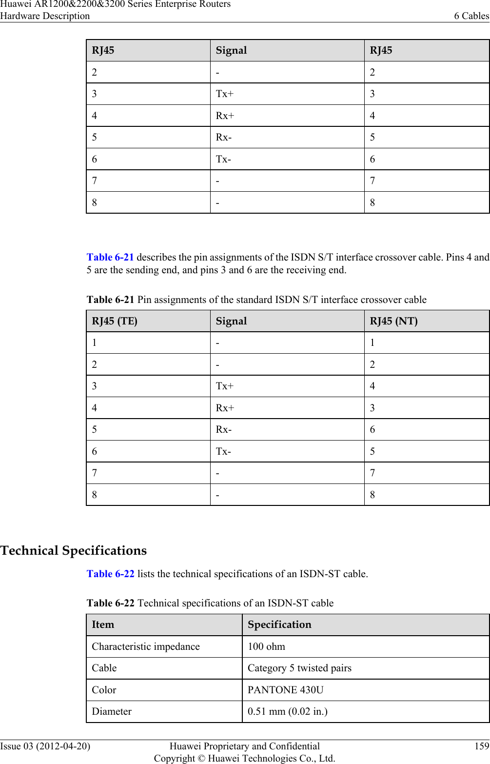
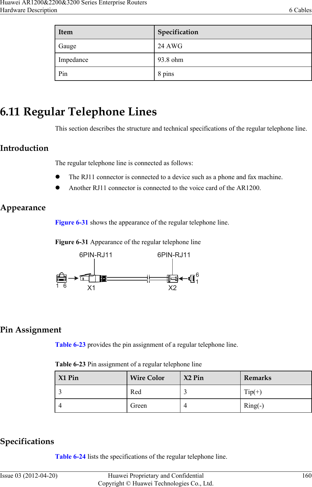
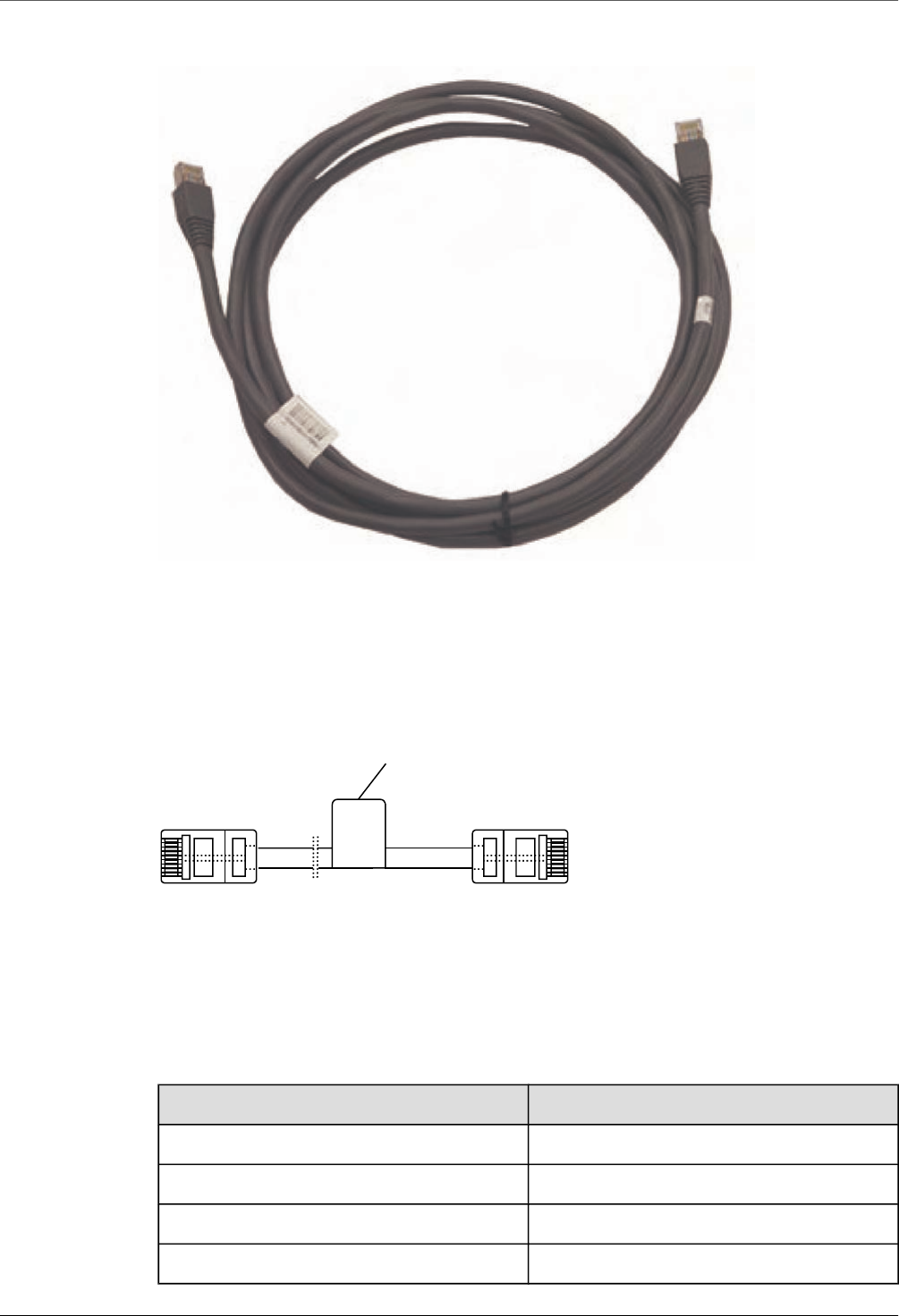
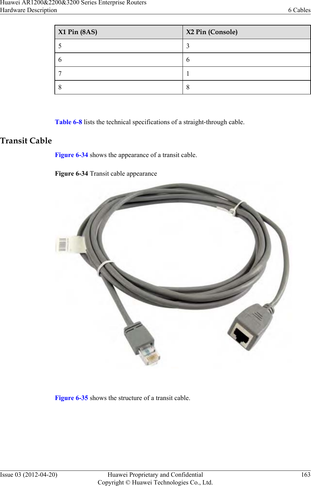
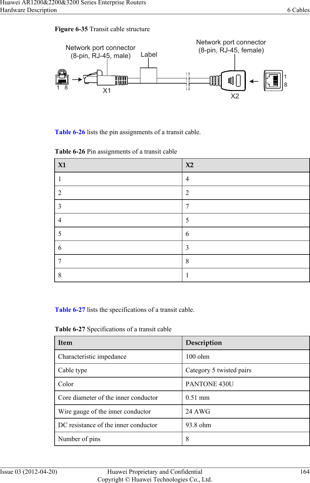
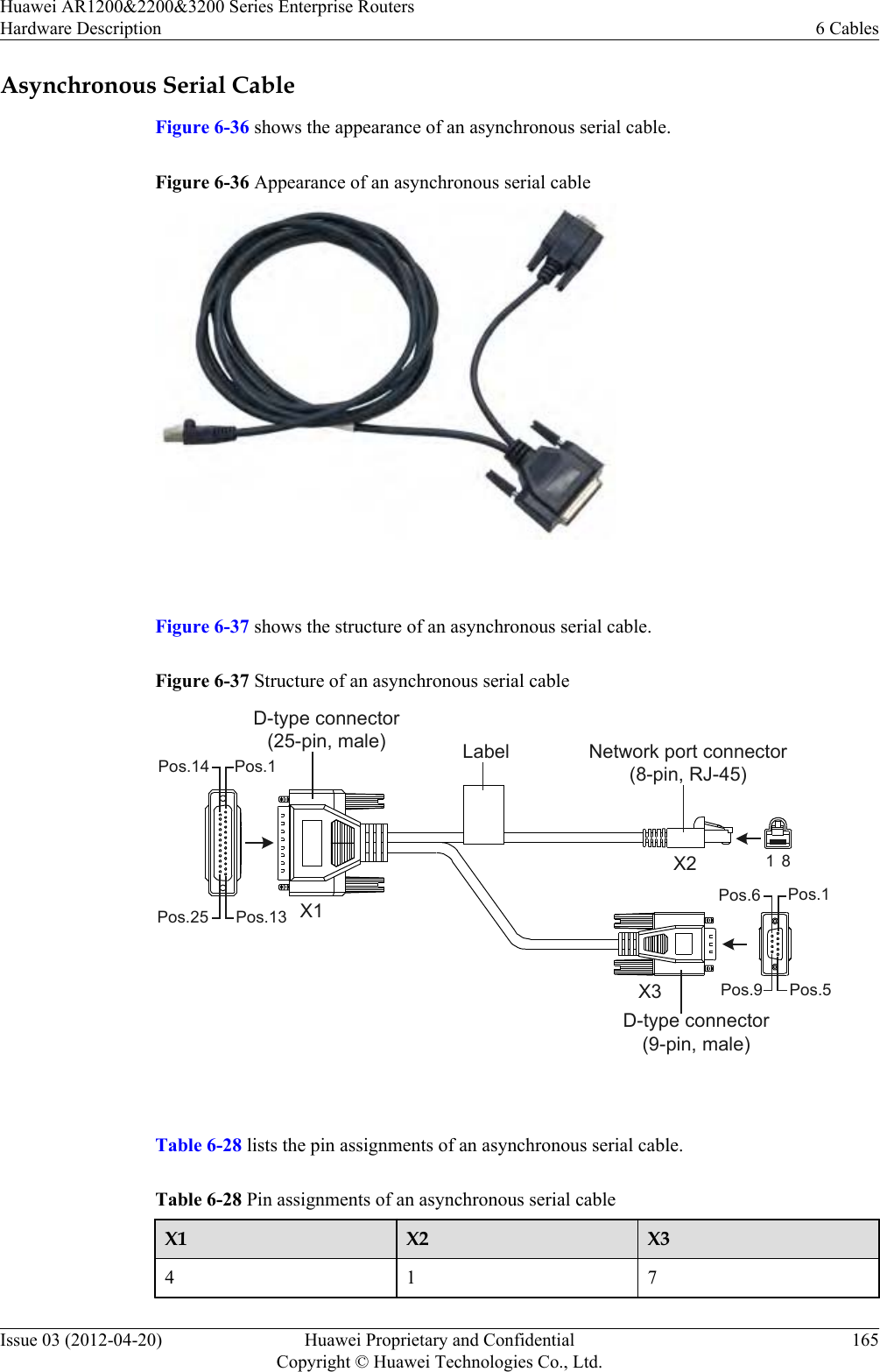
![Table 6-3 Specifications of the ground cableItem DescriptionCable type Power cableColor Green-yellowConnector type (X1/X2) OT/OT naked crimping terminalGauge 10 AWG (cross-sectional area ≈ 5.2 mm2[0.0081 in.2])Cable type lStandards compliance: H07Z-K UL3386lLength: 0.3 mMaximum current 50.0 AFireproof level VW-1, CSA FT1 6.4 Console CableA console cable is used to debug or maintain a local device.ApplicationA console cable connects the console port of the device to the serial port of an operation terminalto transmit configuration data. A shielded cable or an unshielded cable can be used accordingto the onsite situation.A console cable connects the device and terminal as follows:lThe 8-pin RJ45 connector is inserted into the console port of the device.lThe DB9 male connector is connected to an operation terminal, which is usually a PC.Appearance and StructureFigure 6-5 shows the structure of the console cable.Figure 6-5 Structure of the console cableX1Pos.1Pos.9Pos.6Pos.5X2 1 8Network port connector(8-pin, RJ-45)D-type connector(9-pin, male)Label Huawei AR1200&2200&3200 Series Enterprise RoutersHardware Description 6 CablesIssue 03 (2012-04-20) Huawei Proprietary and ConfidentialCopyright © Huawei Technologies Co., Ltd.135](https://usermanual.wiki/Huawei-Technologies/AR1220WIFI.User-manual-III/User-Guide-1716095-Page-142.png)
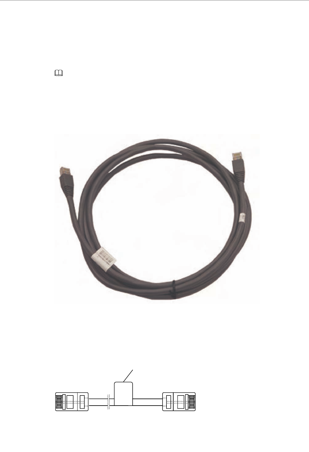
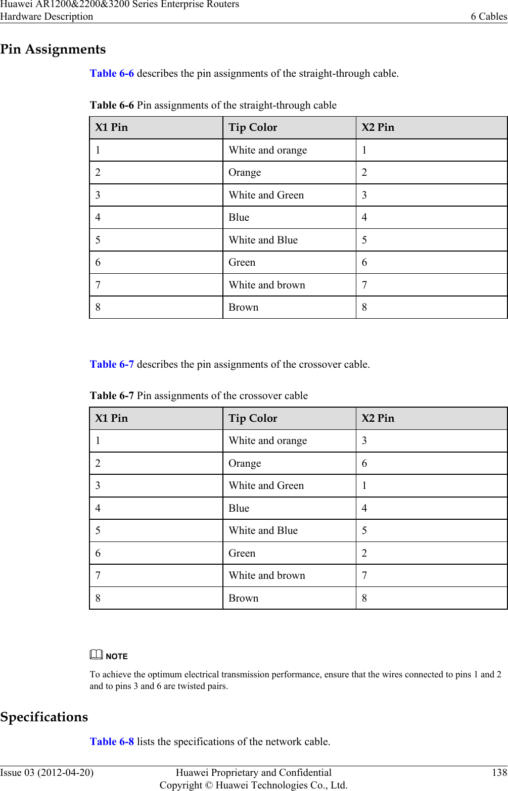
![Pin AssignmentsTable 6-4 describes the pin assignments of the console cable.Table 6-4 Pin assignments of the console cableConnector X1(DB9) X2(RJ45)Pin assignment 2 33 65 5 SpecificationsTable 6-5 lists the specifications of the console cable.Table 6-5 Specifications of the console cableItem DescriptionConnector type lConnector X1: cable connector, D-type, 9-pin, malelConnector X2: network interface connector, RJ45, 8-pin, 8-bit, maleCable type Twisted pairColor PANTONE WARM GRAY 1UDiameter 0.32 mm (0.13 in.)Gauge 28 AWG (cross-sectional area ≈ 0.08 mm2 [0.0002 in.2])Pin 2 pairsLength 3 m (9.85 ft.) 6.5 Network CableA network cable subtends devices, enables a device to communication with other networkdevices, and allows users to locally or remotely maintain the device.ApplicationA network cable connects a maintenance terminal to the console port on the main control boardfor local or remote maintenance.The network cables are classified into straight-through cables and crossover cables.Huawei AR1200&2200&3200 Series Enterprise RoutersHardware Description 6 CablesIssue 03 (2012-04-20) Huawei Proprietary and ConfidentialCopyright © Huawei Technologies Co., Ltd.136](https://usermanual.wiki/Huawei-Technologies/AR1220WIFI.User-manual-III/User-Guide-1716095-Page-143.png)