Huawei Technologies BTS3006C Outdoor BTS with dual-density TRX User Manual 00 1 Title Page
Huawei Technologies Co.,Ltd Outdoor BTS with dual-density TRX 00 1 Title Page
UserManual.wiki
>
Huawei Technologies
>
BTS3006C User Manual
User Manual
Navigation menu
Upload a User Manual
Namespaces
Wiki Guide
HTML
PDF
Info
Views
User Manual
Discussion / Help
Navigation

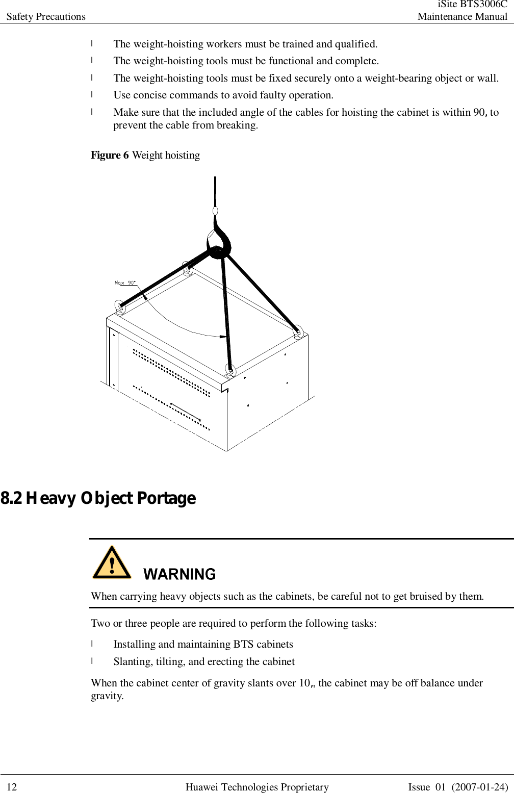
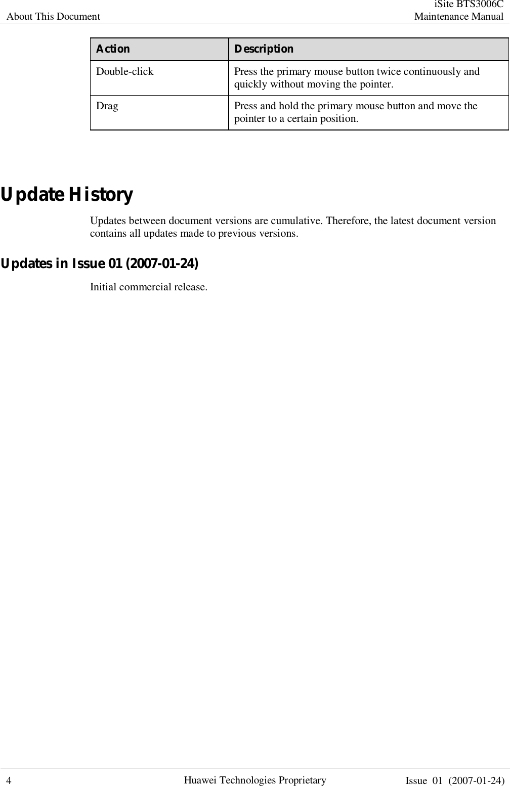
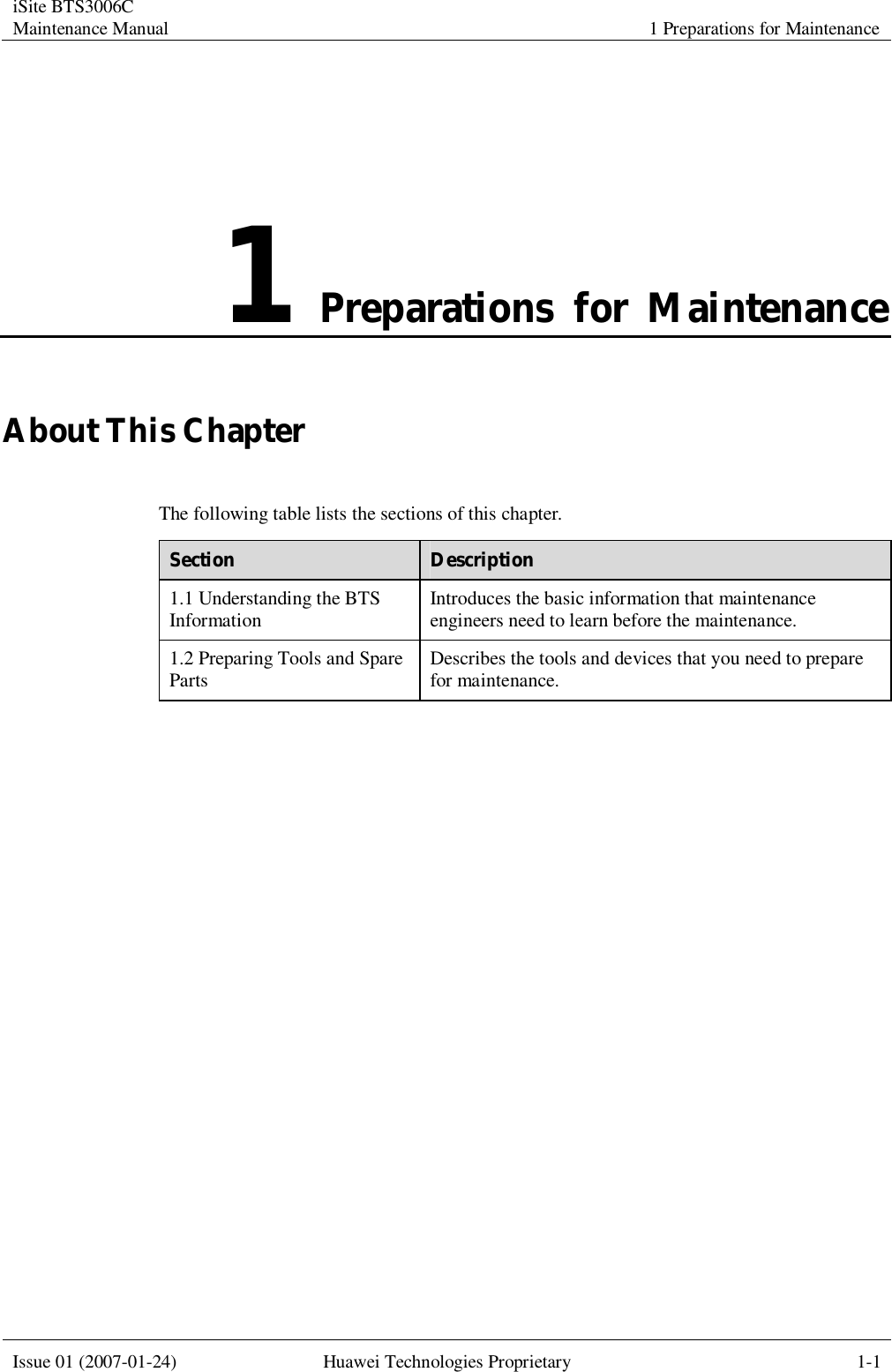
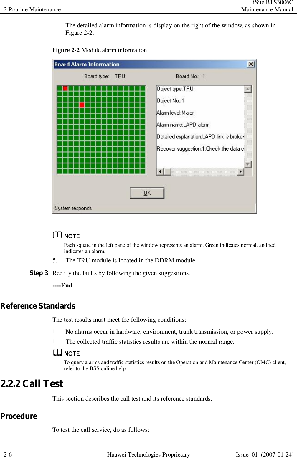
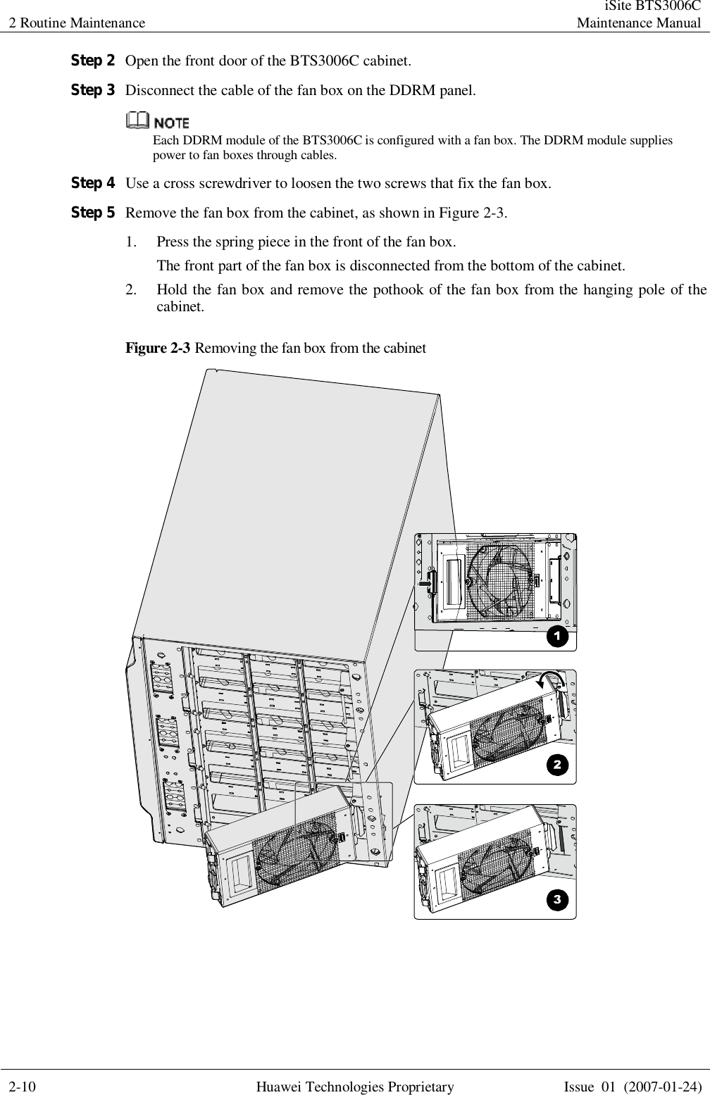
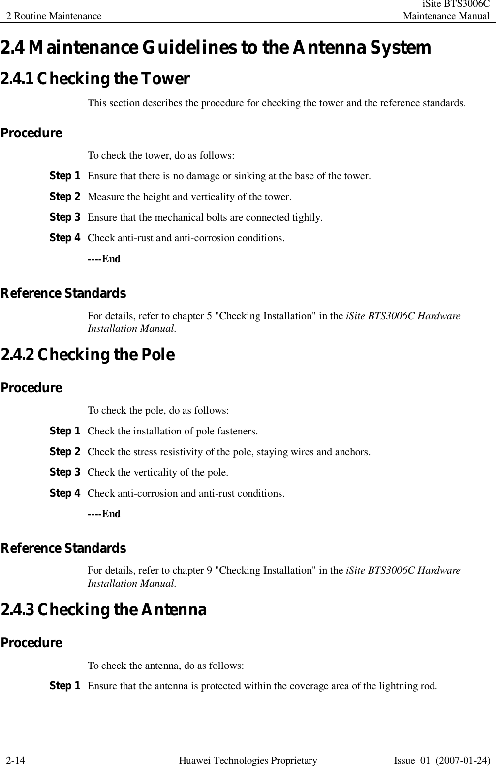
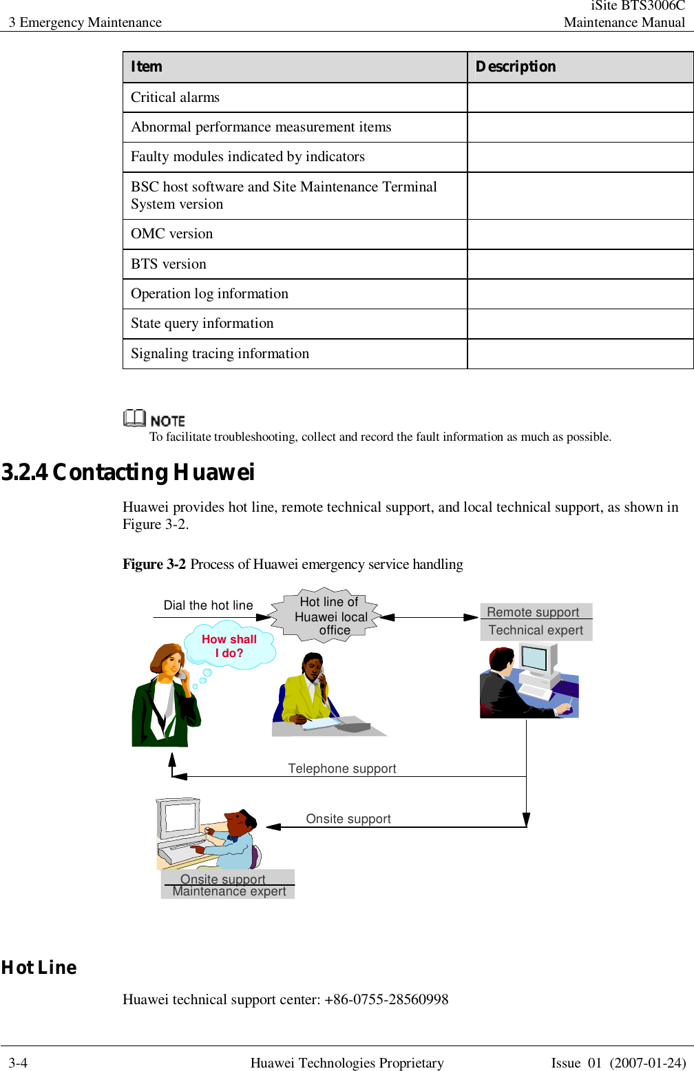
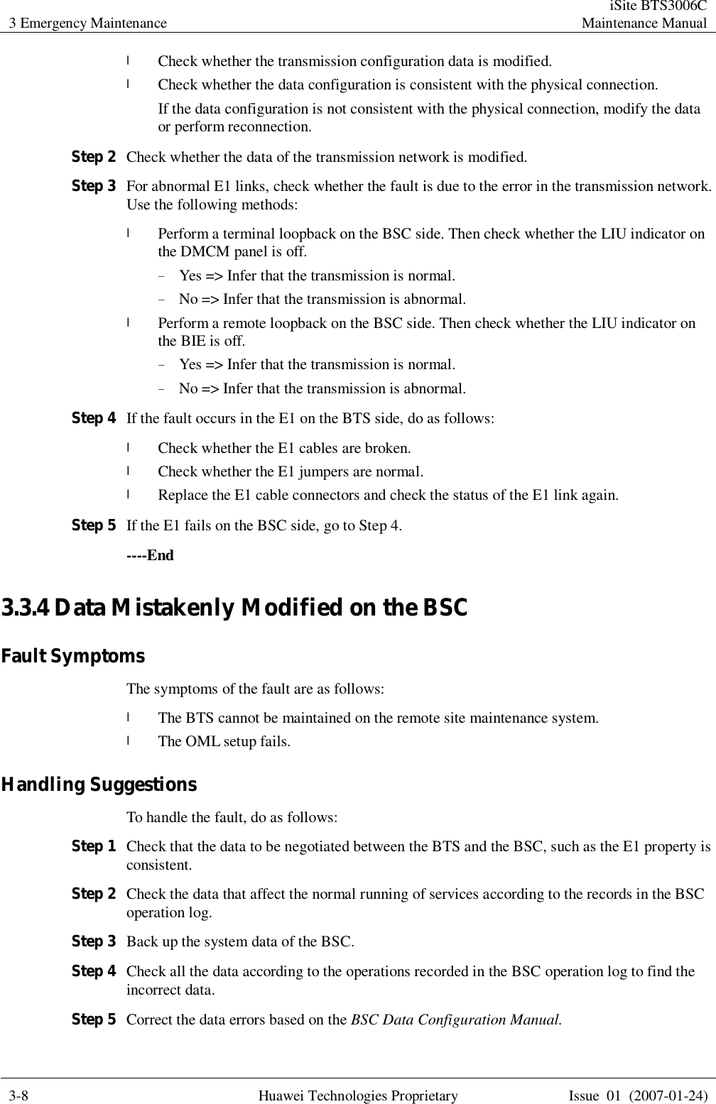
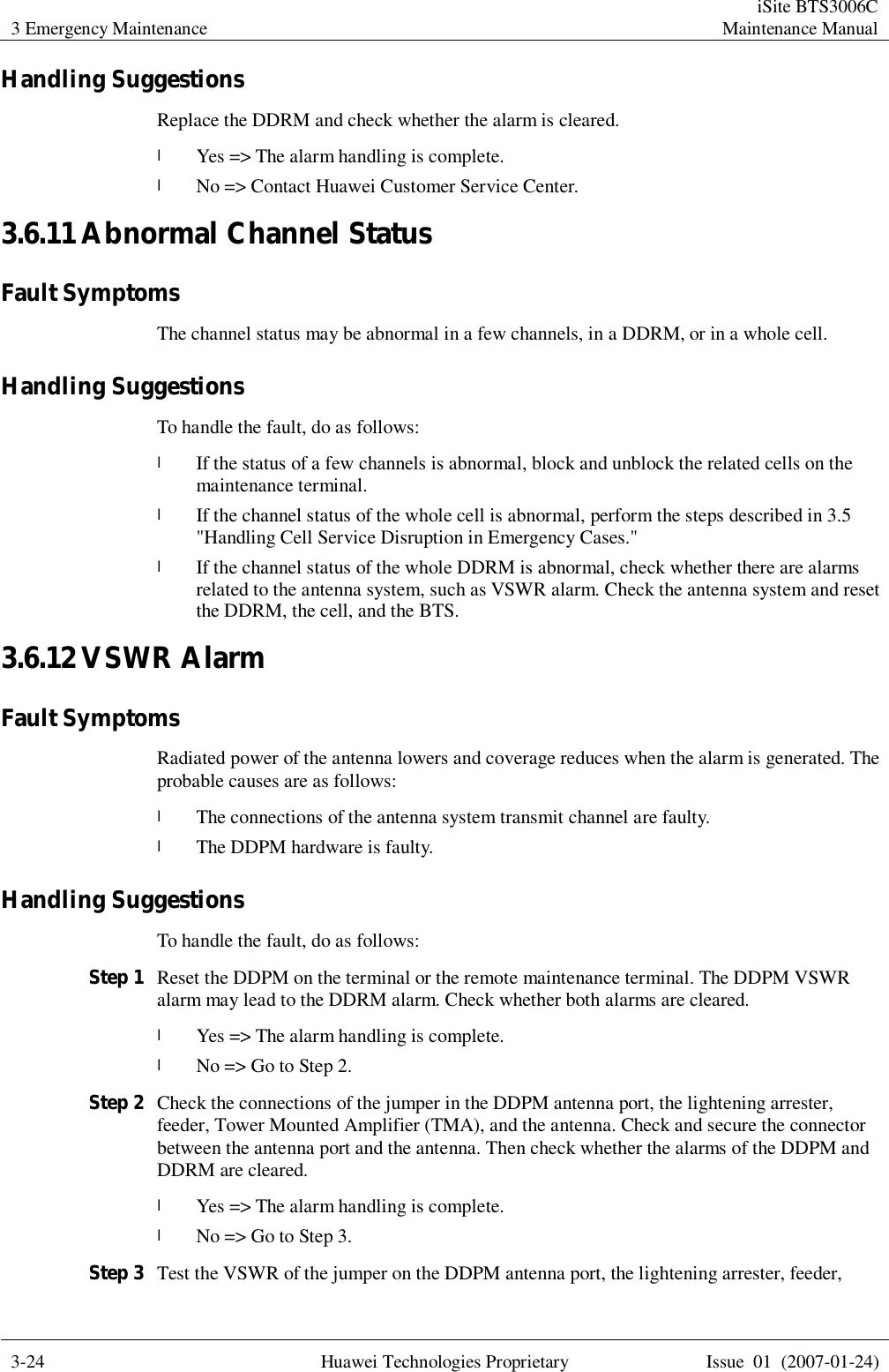
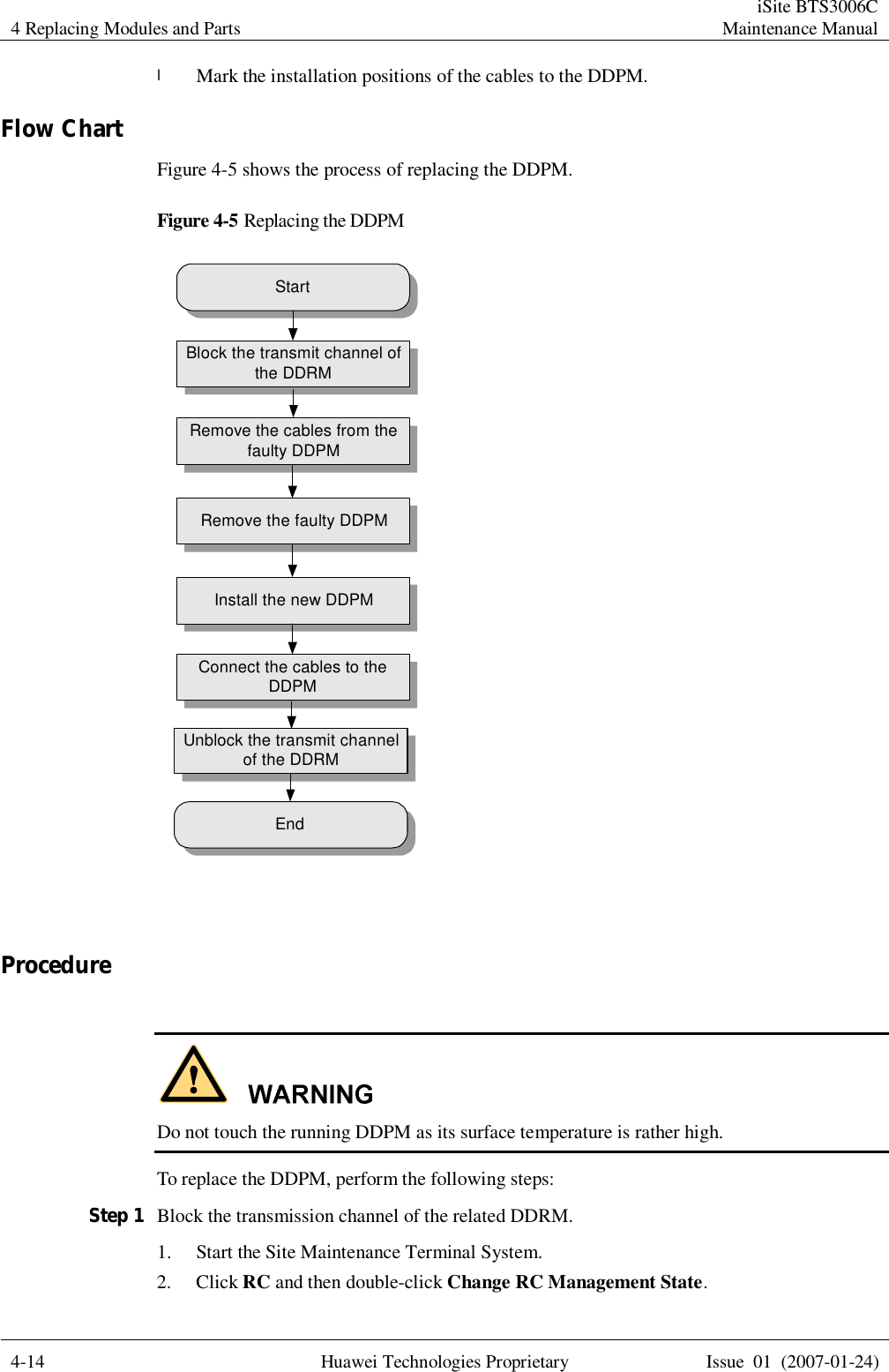
![iSite BTS3006C Maintenance Manual About This Document Issue 01 (2007-01-24) Huawei Technologies Proprietary 3 Command Conventions Convention Description Boldface The keywords of a command line are in boldface. Italic Command arguments are in italics. [ ] Items (keywords or arguments) in square brackets [ ] are optional. { x | y | ... } Alternative items are grouped in braces and separated by vertical bars. One is selected. [ x | y | ... ] Optional alternative items are grouped in square brackets and separated by vertical bars. One or none is selected. { x | y | ... } * Alternative items are grouped in braces and separated by vertical bars. A minimum of one or a maximum of all can be selected. GUI Conventions Convention Description Boldface Buttons, menus, parameters, tabs, windows, and dialog titles are in boldface. For example, click OK. > Multi-level menus are in boldface and separated by the ">" signs. For example, choose File > Create > Folder. Keyboard Operation Format Description Key Press the key. For example, press Enter and press Tab. Key 1+Key 2 Press the keys concurrently. For example, pressing Ctrl+Alt+A means the three keys should be pressed concurrently. Key 1, Key 2 Press the keys in turn. For example, pressing Alt, A means the two keys should be pressed in turn. Mouse Operation Action Description Click Select and release the primary mouse button without moving the pointer.](https://usermanual.wiki/Huawei-Technologies/BTS3006C/User-Guide-872161-Page-36.png)