Huawei Technologies BTS3601C-800 CDMA Base Station User Manual 1
Huawei Technologies Co.,Ltd CDMA Base Station Users Manual 1
UserManual.wiki
>
Huawei Technologies
>
BTS3601C-800 User Manual
>
Users Manual 1
Contents
1.
Users Manual 1
2.
Users Manual 2
3.
Users Manual 3
Users Manual 1
Navigation menu
Upload a User Manual
Namespaces
Wiki Guide
HTML
PDF
Info
Views
User Manual
Discussion / Help
Navigation
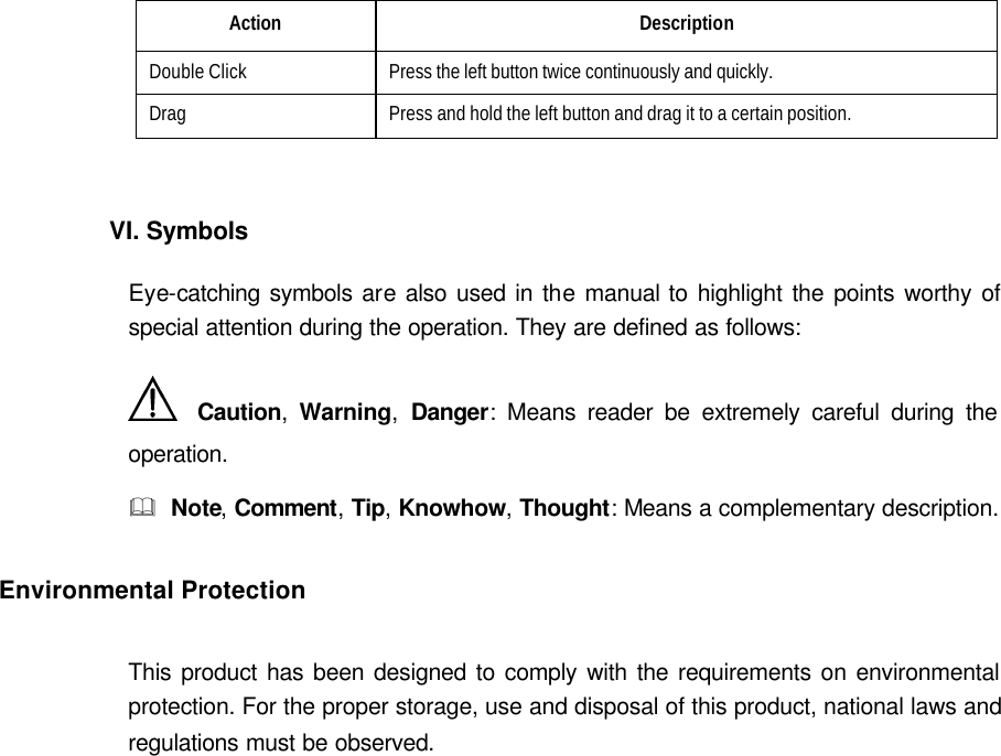
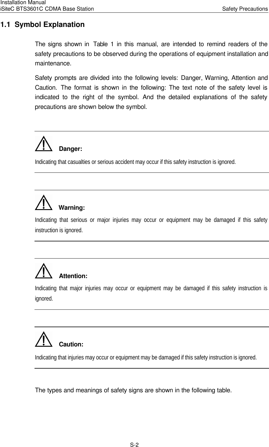
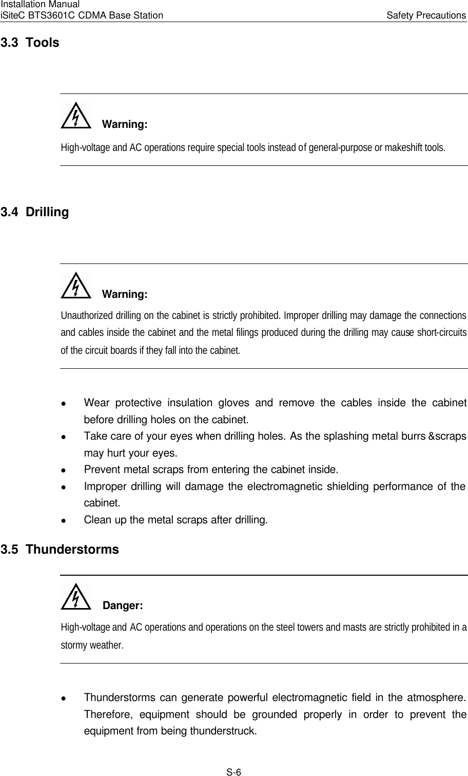
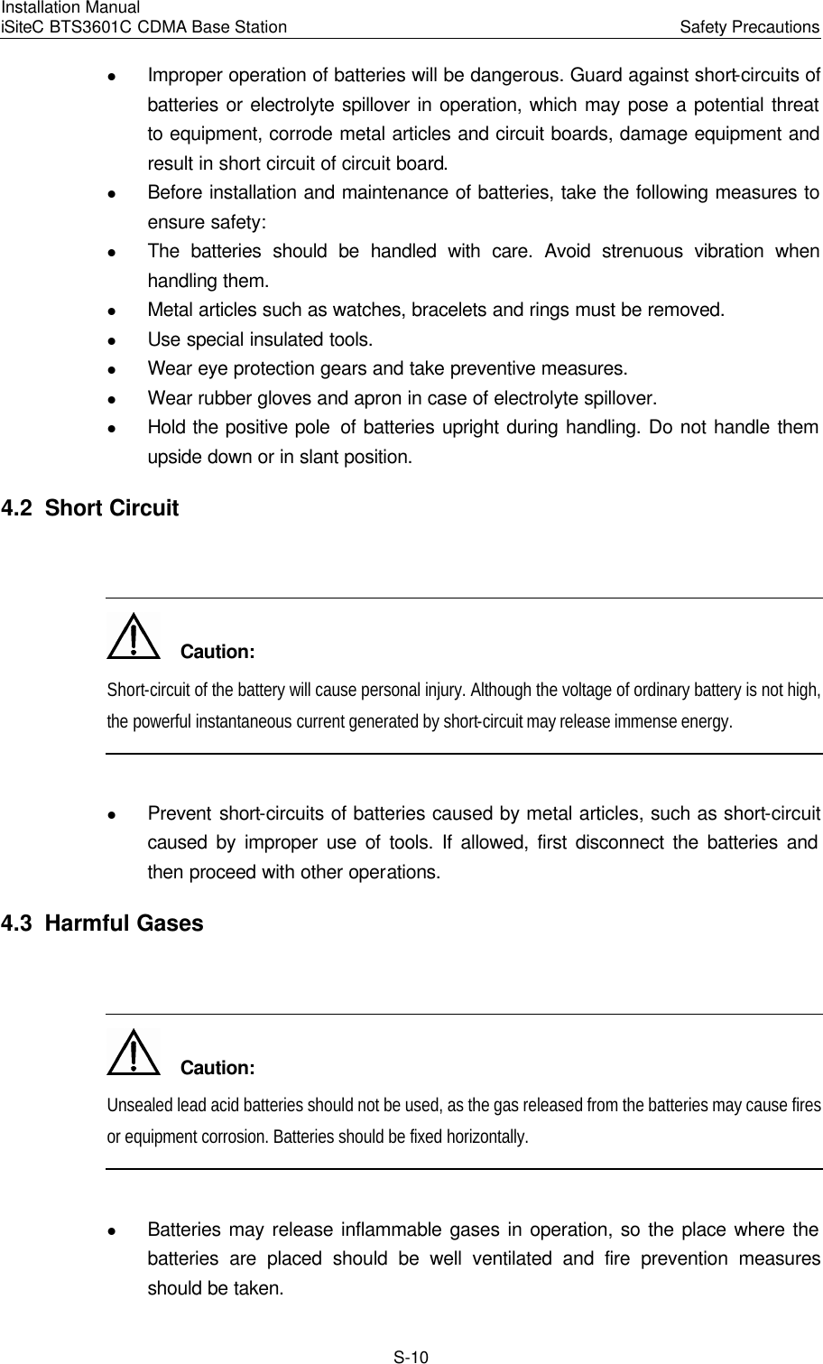
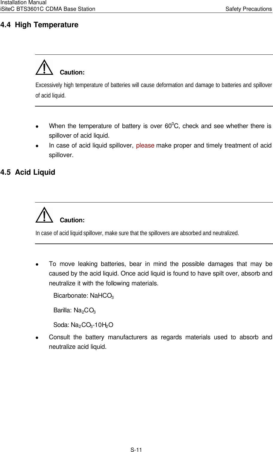
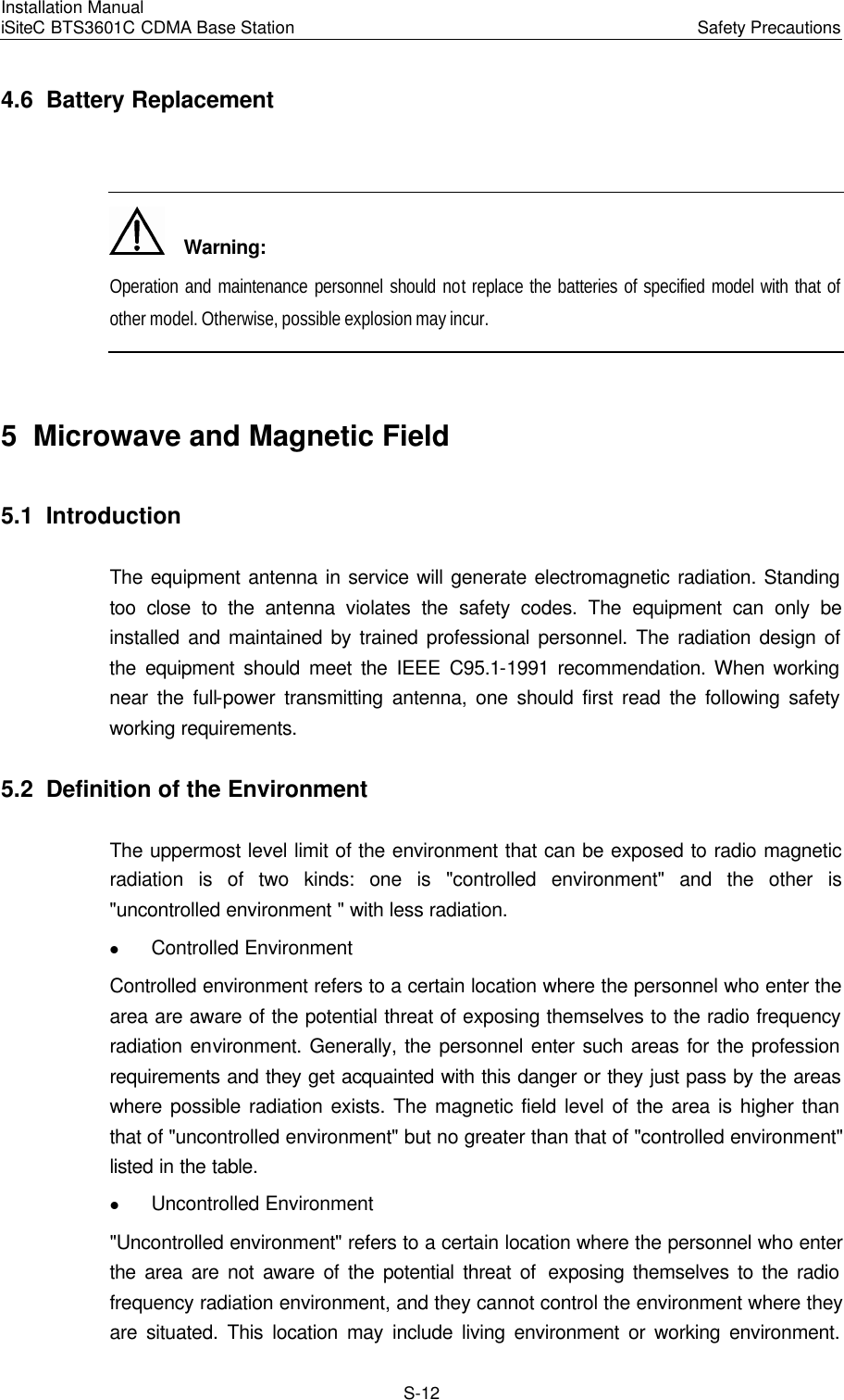
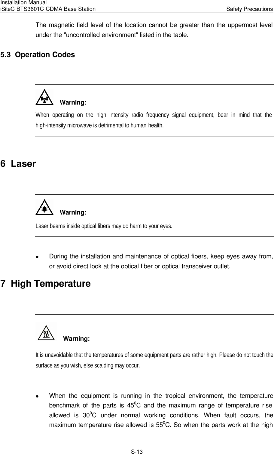
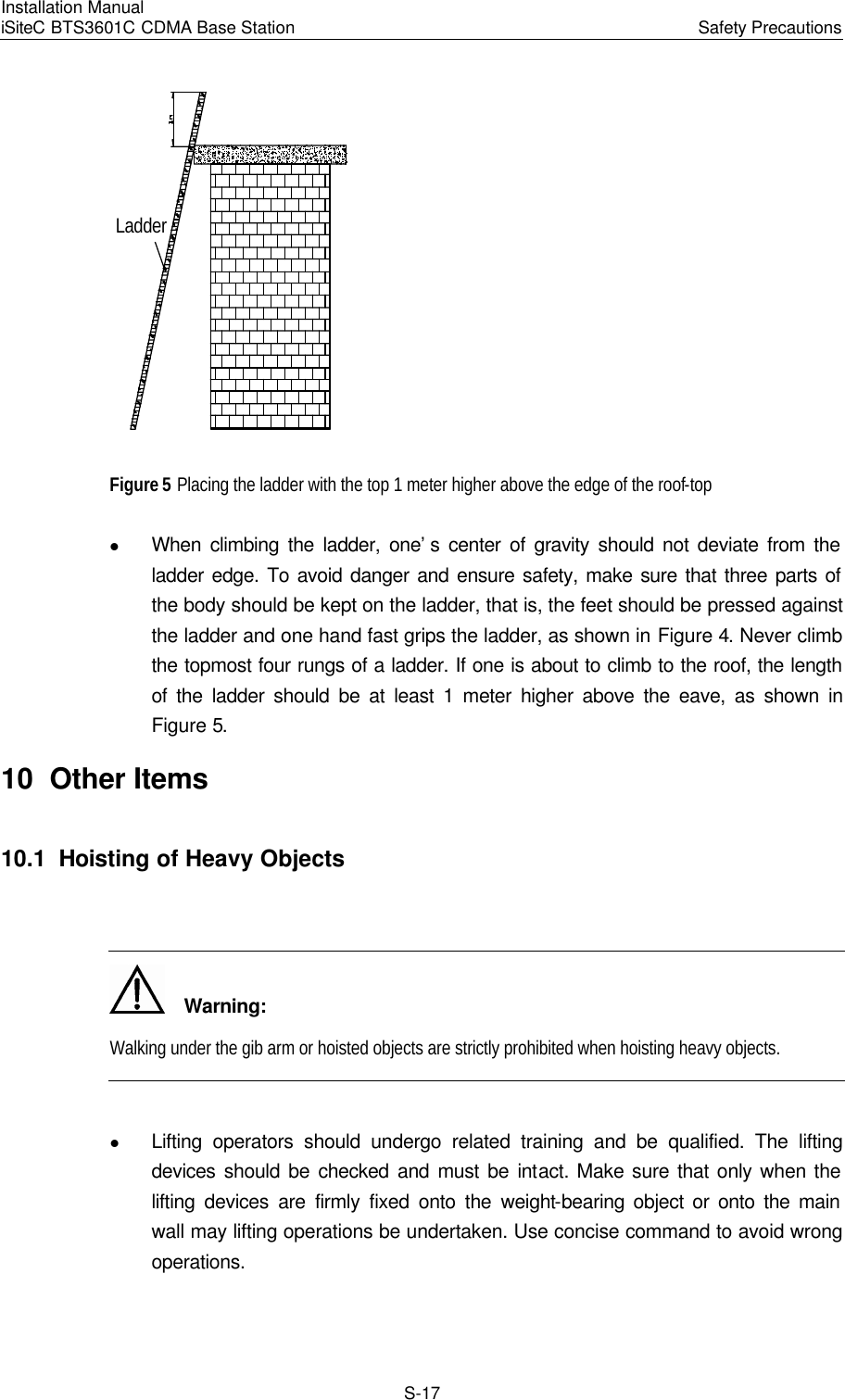
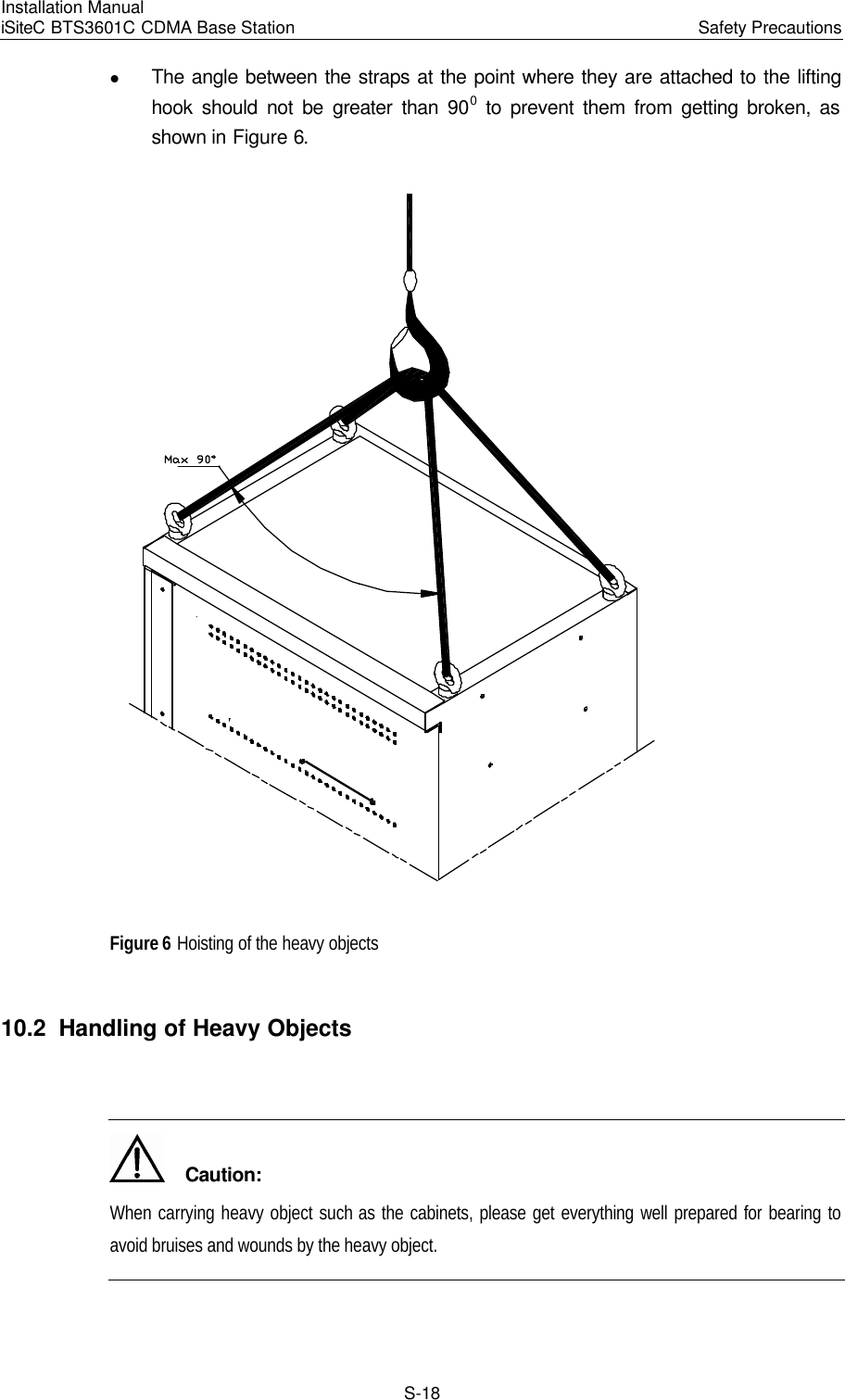
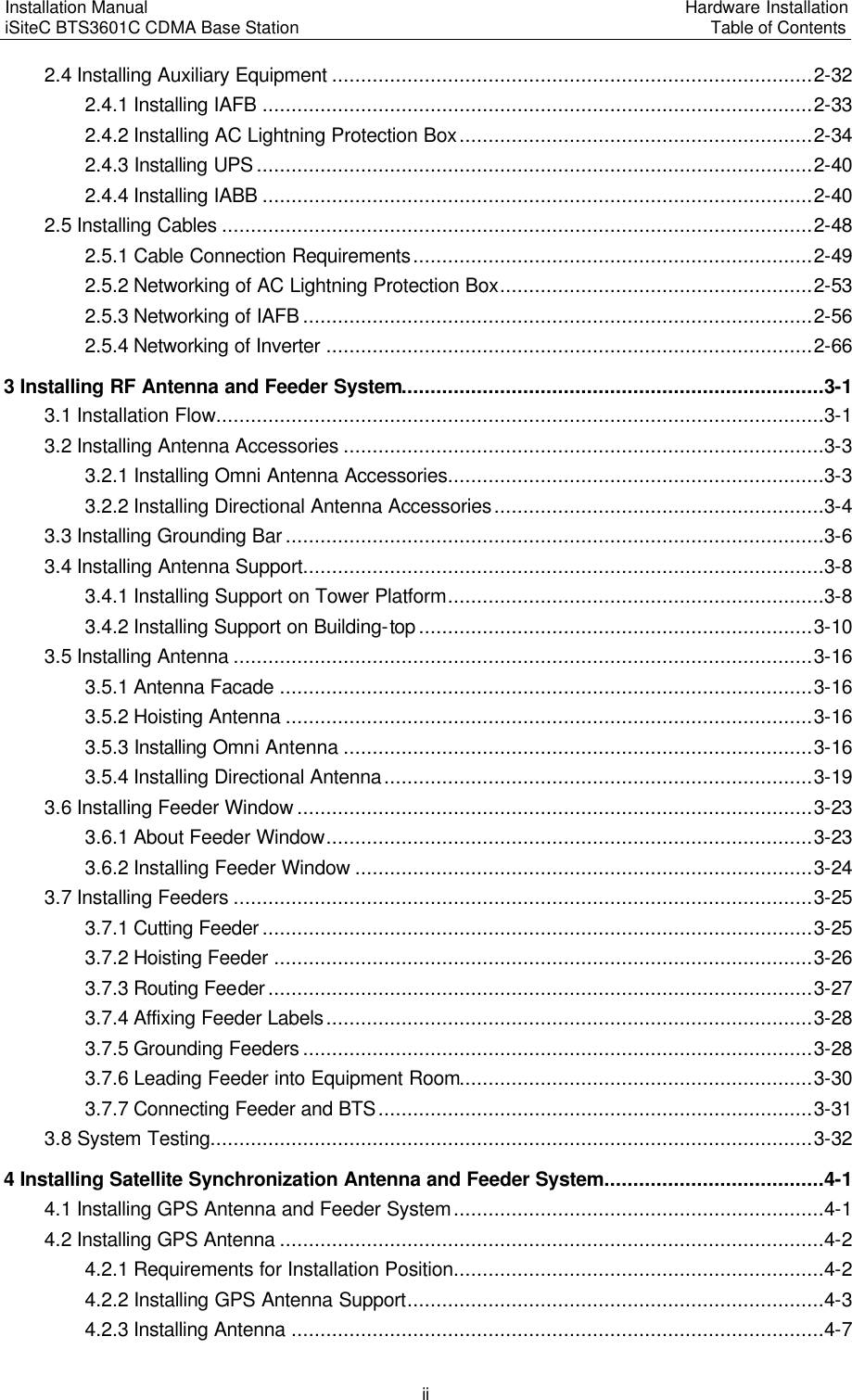
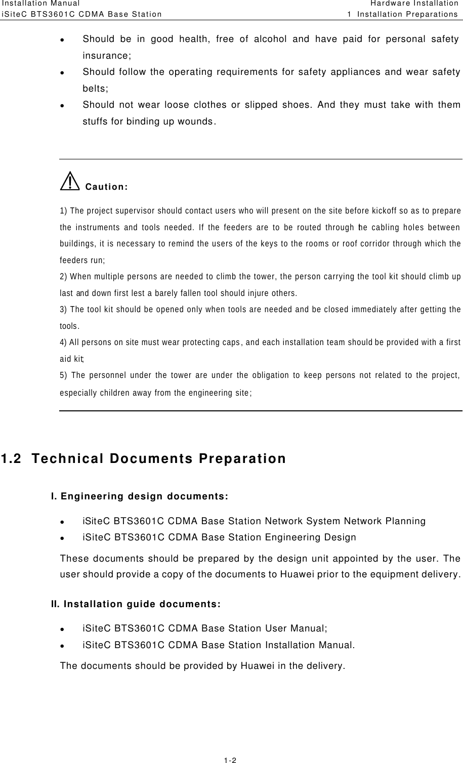
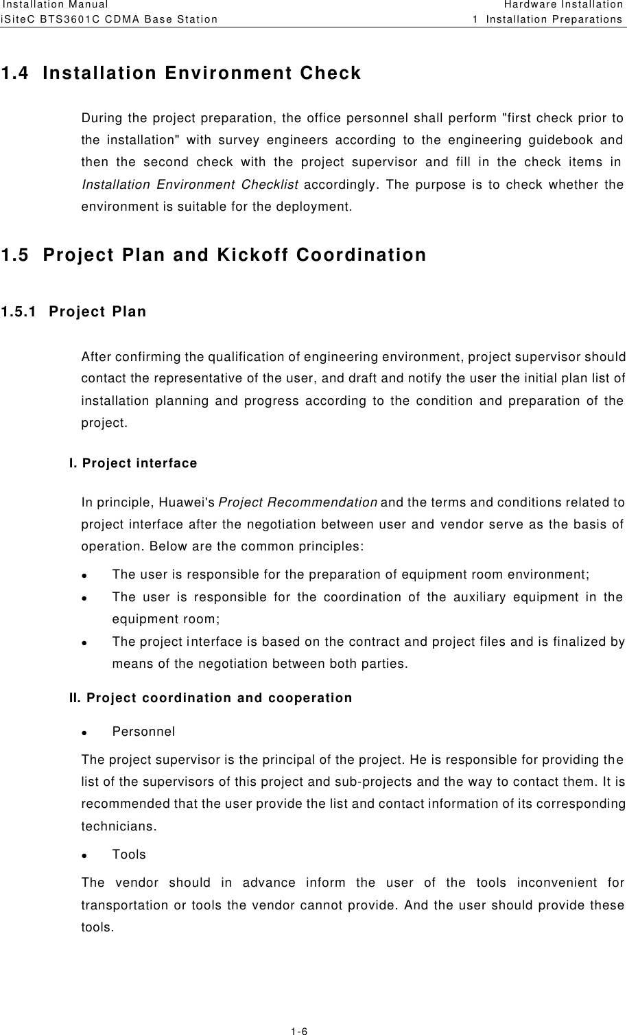
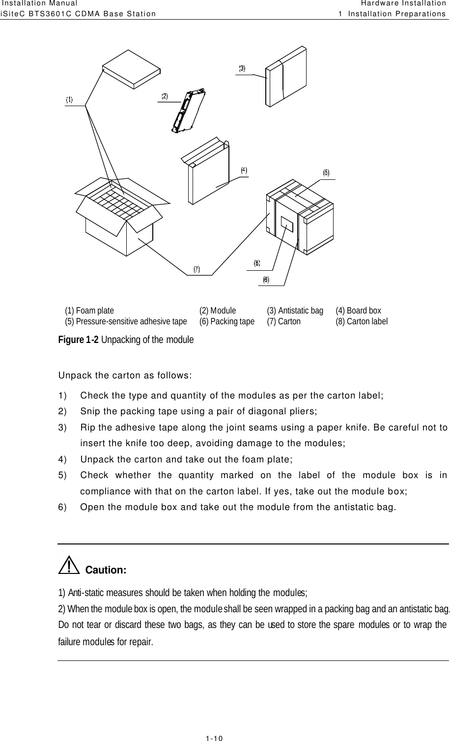
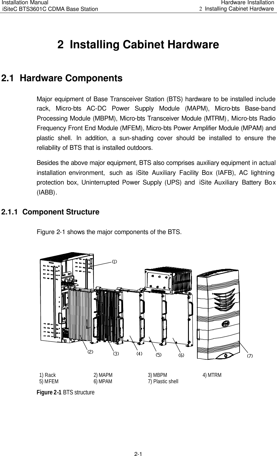
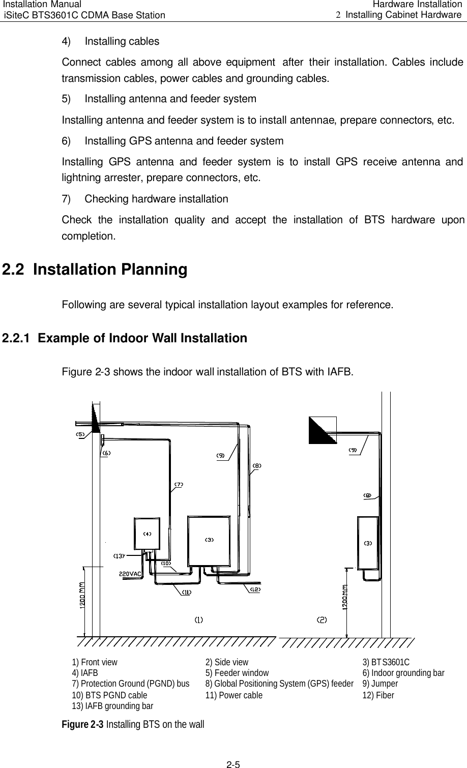
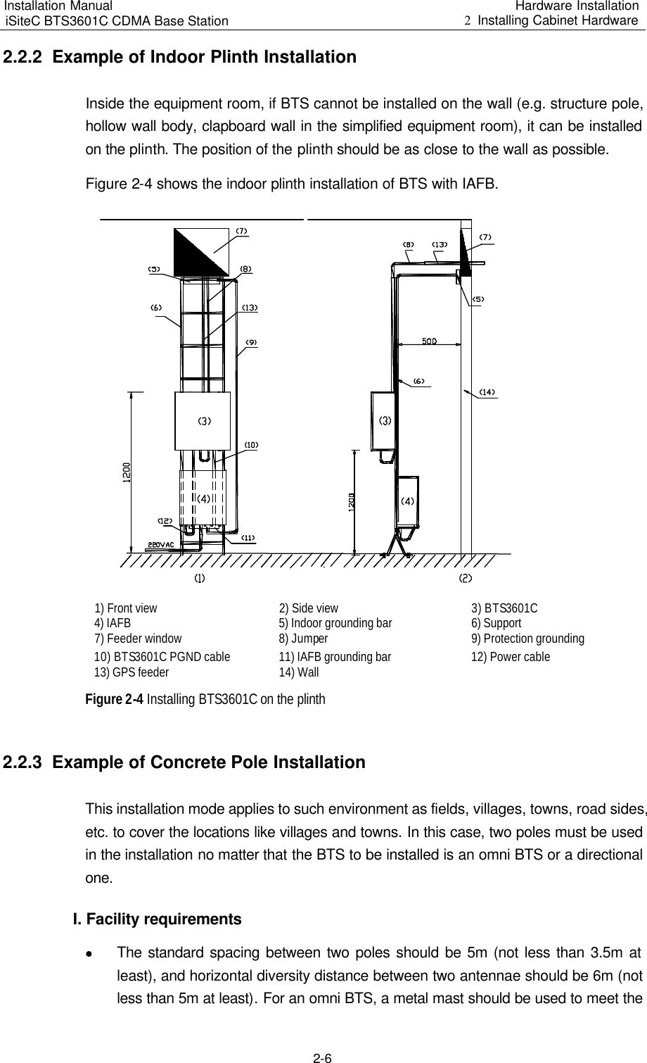
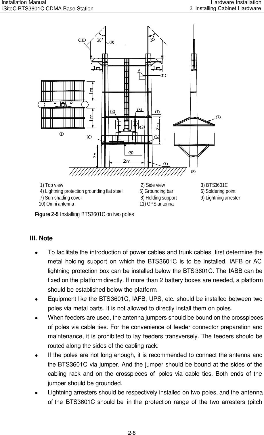
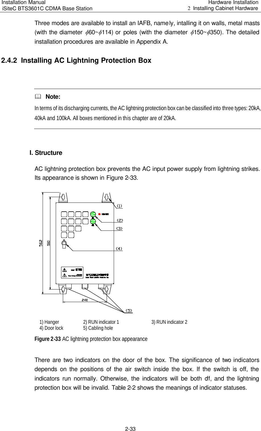
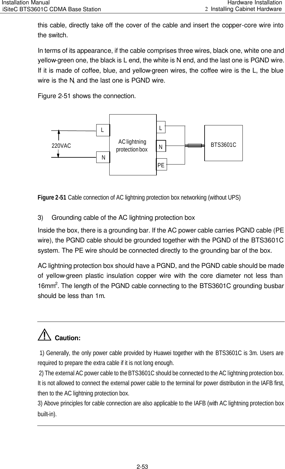
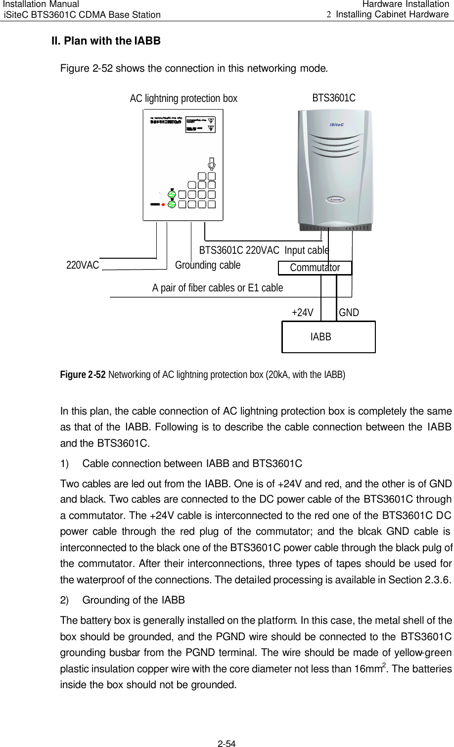
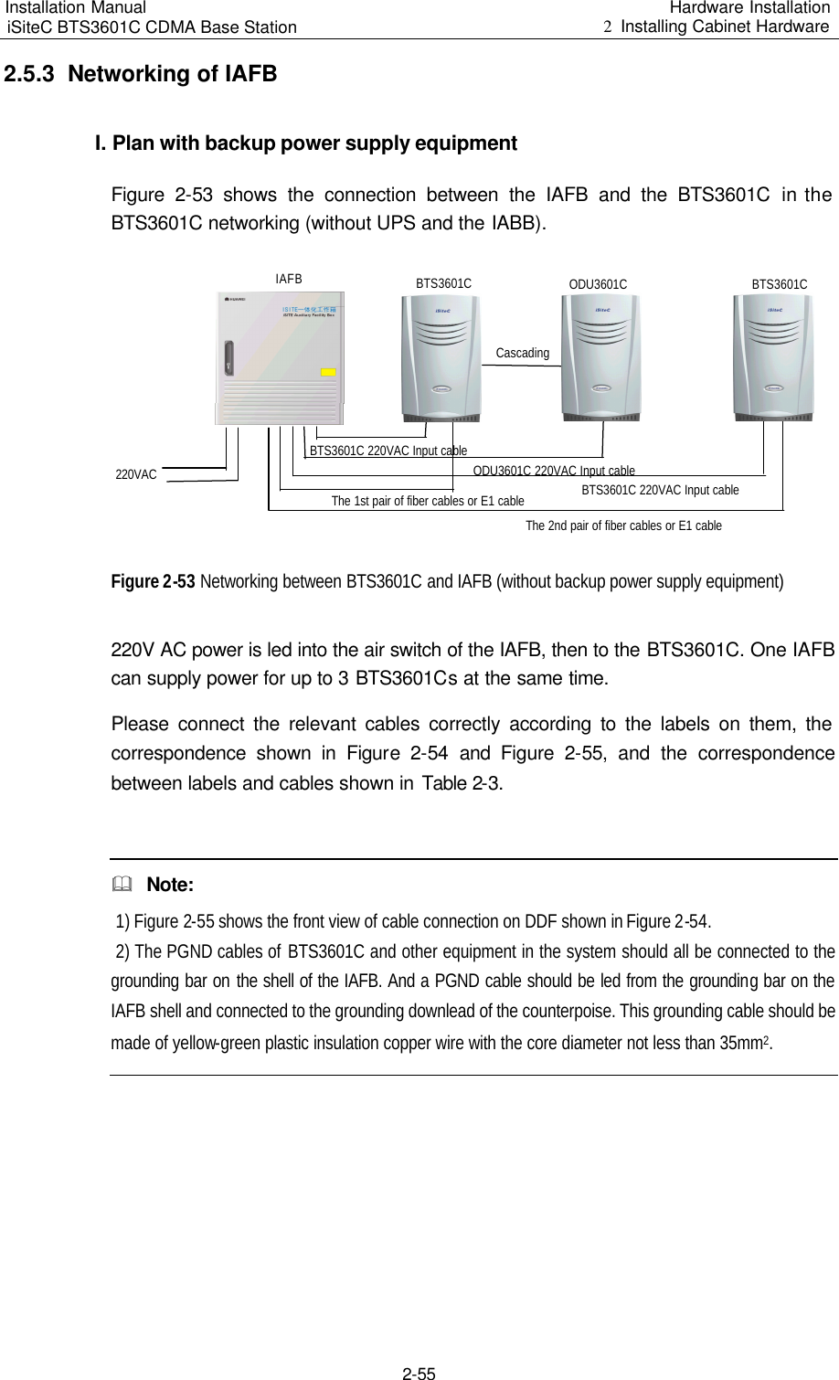
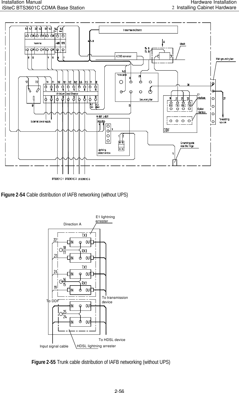
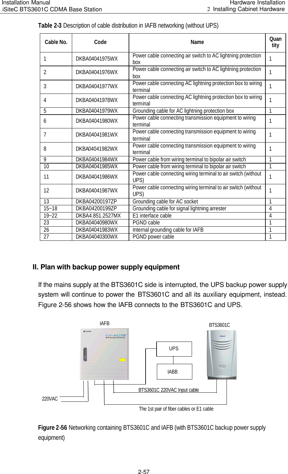
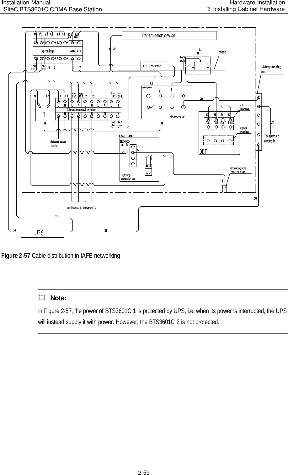
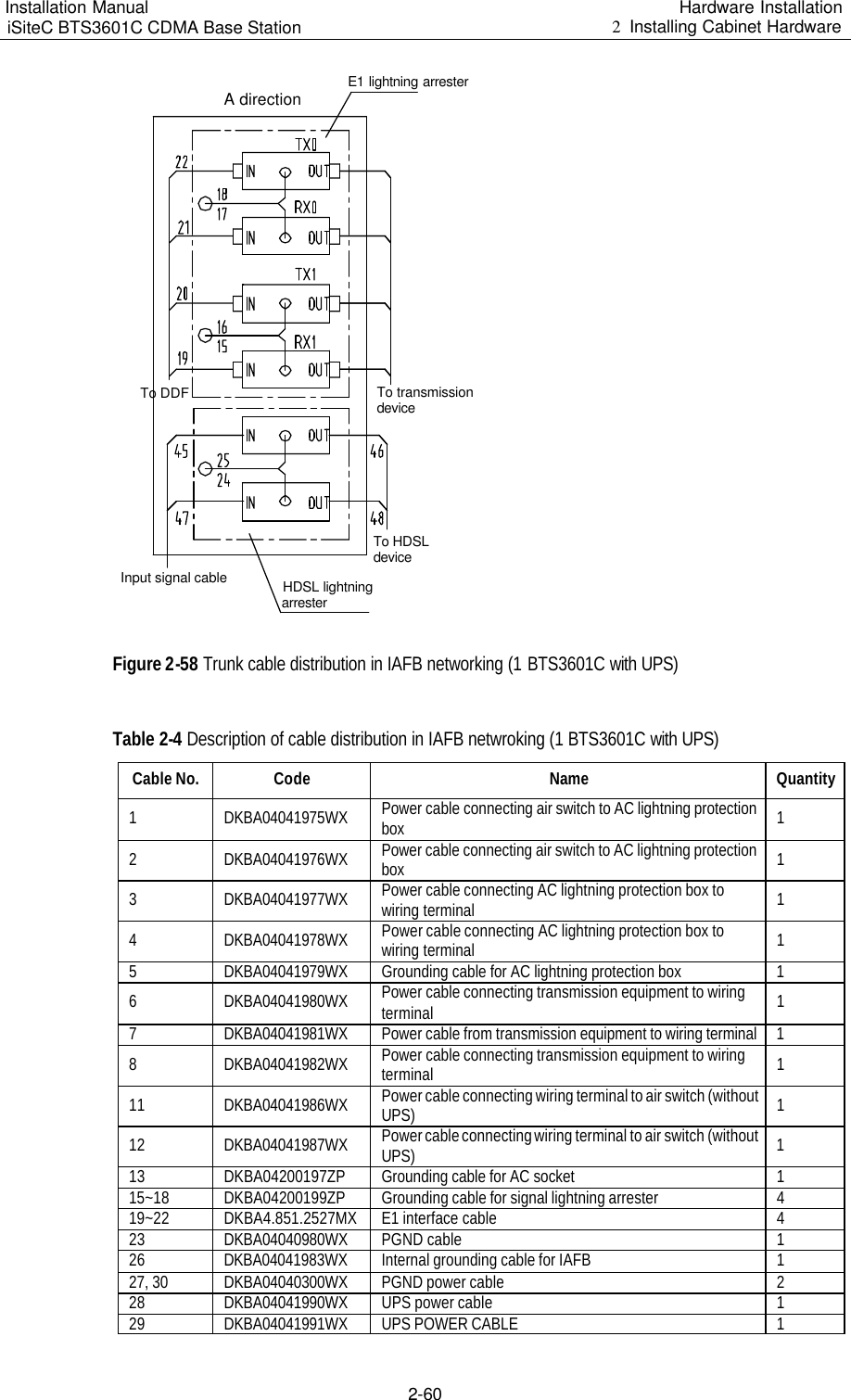
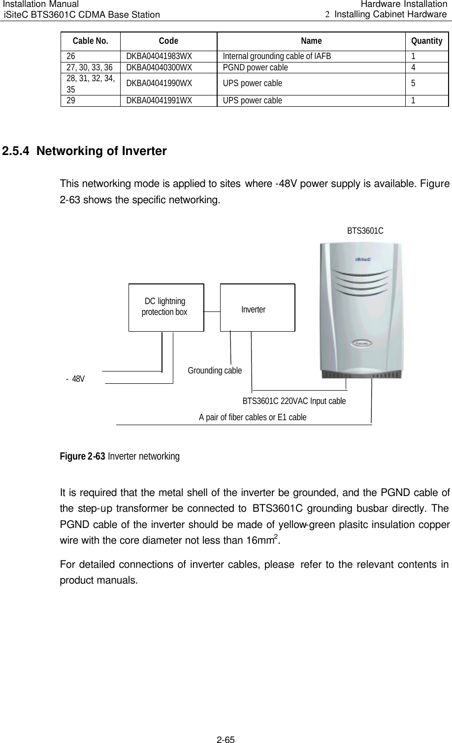
![II. Command conventions Convention Description Boldface The keywords of a command line are in Boldface. italic Command arguments are in italic. [ ] Items (keywords or arguments) in square brackets [ ] are optional. { x | y | ... } Alternative items are grouped in braces and separated by vertical bars. One is selected. [ x | y | ... ] Optional alternative items are grouped in square brackets and separated by vertical bars. One or none is selected. { x | y | ... } * Alternative items are grouped in braces and separated by vertical bars. A minimum of one or a maximum of all can be selected. [ x | y | ... ] * Optional alternative items are grouped in square brackets and separated by vertical bars. Many or none can be selected. III. GUI conventions Convention Description < > Button names are inside angle brackets. For example, click <OK> button. [ ] Window names, menu items, data table and field names are inside square brackets. For example, pop up the [New User] window. / Multi-level menus are separated by forward slashes. For example, [File/Create/Folder]. IV. Keyboard operation Format Description <Key> Press the key with the key name inside angle brackets. For example, <Enter>, <Tab>, <Backspace>, or <A>. <Key1+Key2> Press the keys concurrently. For example, <Ctrl+Alt+A> means the three keys should be pressed concurrently. <Key1, Key2> Press the keys in turn. For example, <Alt, A> means the two keys should be pressed in turn. V. Mouse operation Action Description Click Press the left button or right button quickly (left button by default).](https://usermanual.wiki/Huawei-Technologies/BTS3601C-800.Users-Manual-1/User-Guide-469342-Page-5.png)