Huawei Technologies BTS3601C-800 CDMA Base Station User Manual 2
Huawei Technologies Co.,Ltd CDMA Base Station Users Manual 2
UserManual.wiki
>
Huawei Technologies
>
BTS3601C-800 User Manual
>
Users Manual 2
Contents
1.
Users Manual 1
2.
Users Manual 2
3.
Users Manual 3
Users Manual 2
Navigation menu
Upload a User Manual
Namespaces
Wiki Guide
HTML
PDF
Info
Views
User Manual
Discussion / Help
Navigation
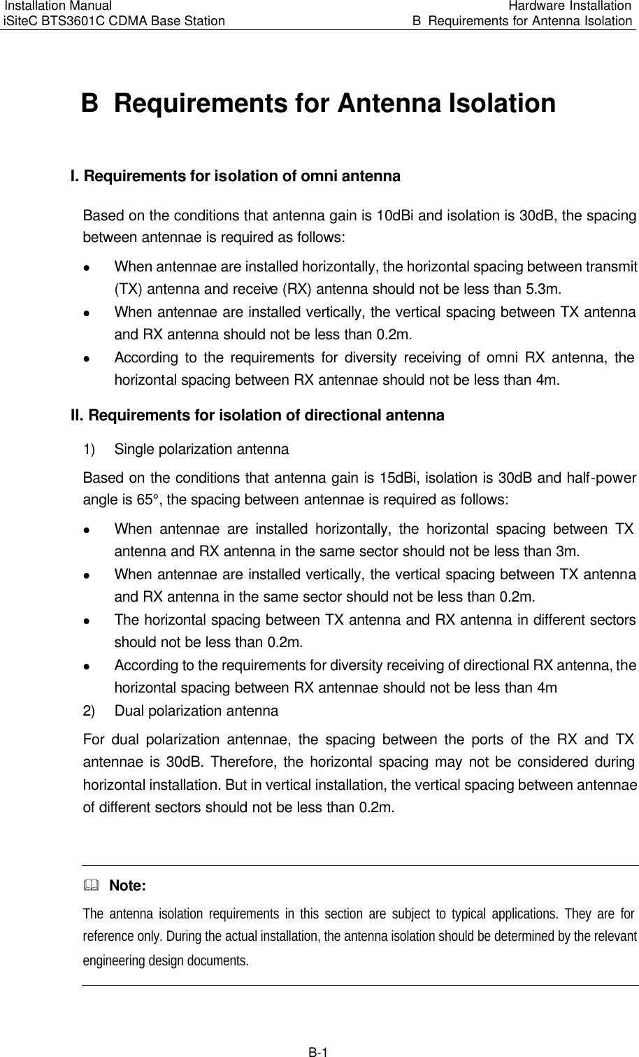
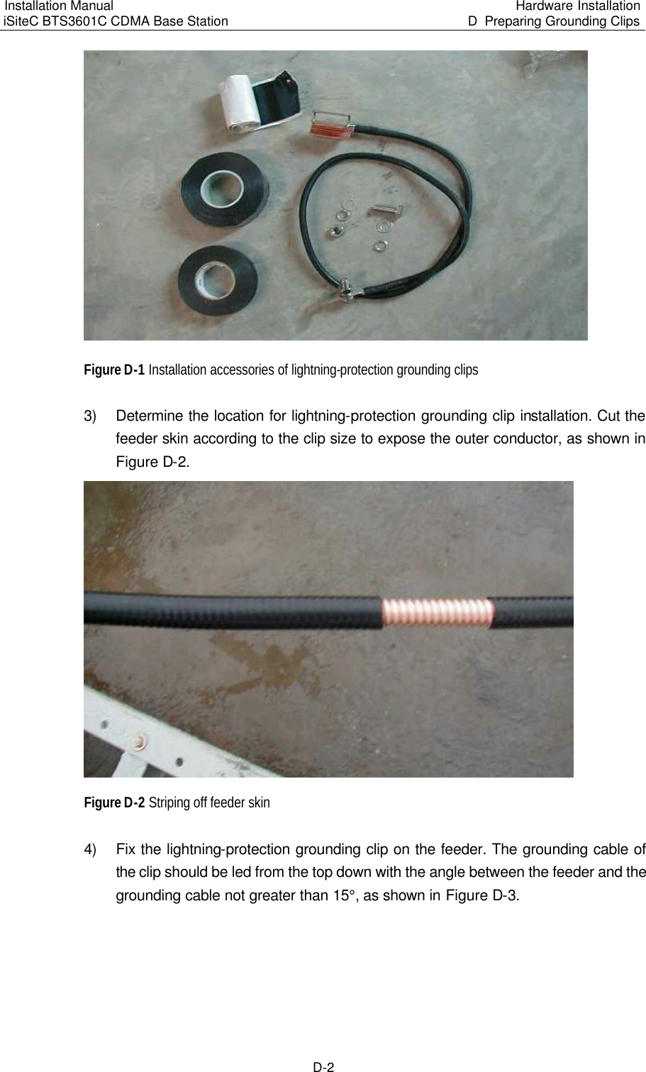
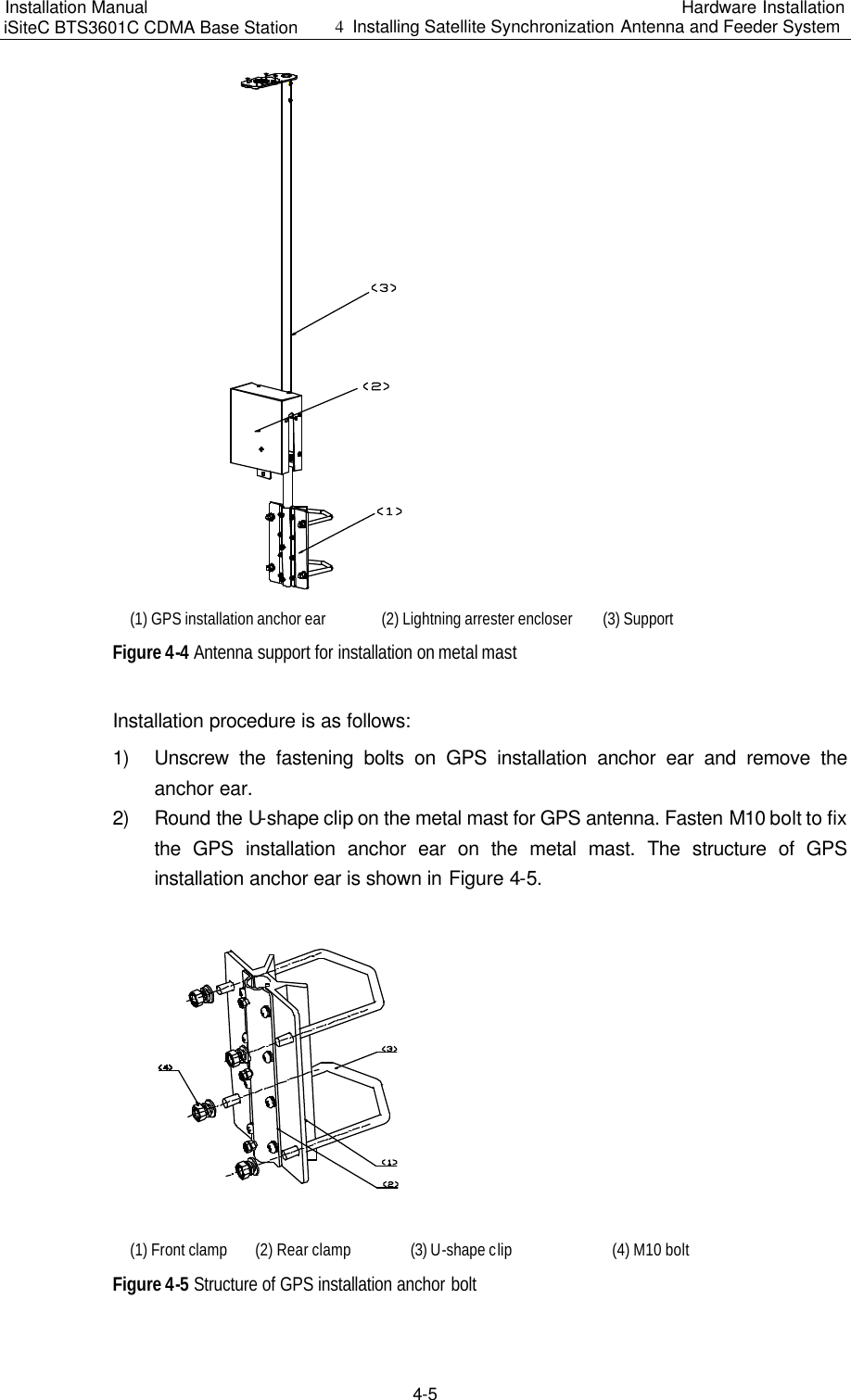
![Installation Manual iSiteC BTS3601C CDMA Base Station Software Installation & System Commissioning 0错误 表格结果无效 3-4 III. Trouble shooting Case One: Failed to activate after successful downloading. Cause analysis: Incorrect parameter for software downloading command, e.g., wrong software version No., may result in unsuccessful activation after successful downloading. Case two: Failed to download. Cause analysis: Check the loading sequence first. If that is fine, check the following: l Is the BAM FTP server powered on? l Is the access directory open? l Are the login user name and password correct? l Does the access directory/file exist? IV. Specific process of software downloading 1) Preparing for software downloading Copy the board software to be downloaded to the BTS3601C software loading directory, which is designated in the BAM. Make sure that the file is writable and readable. Meanwhile, note down the software version information. Finally, log in to the BAM through the remote maintenance console after starting the FTP server at BAM side. 2) Adding the software loading information in the remote BTS3610C maintenance system Run the remote maintenance console software (AirBridge cBSS Client), and select BTS Management in the command tree. Select Mini-BTS Management\Mini-BTS Loading Management\Add Mini-BTS Loading Information (MICRO>ADD BTSLDINFO). Click , the shortcut icon of command Create Input Interface, and input the following: l [Board Type]: Select the type of the board whose loading information is to be added. l [Software Type]: Select the type of board software; l [Software Version]: Input the version No. (which must meet the related specification) of the software to be downloaded; l [File Path]: Input the path for the software to be loaded (i.e. the software loading directory in the previous step); l [File Name]: Input the name (the corresponding file name under the software loading directory in the previous step) of the file to be loaded.](https://usermanual.wiki/Huawei-Technologies/BTS3601C-800.Users-Manual-2/User-Guide-469343-Page-52.png)
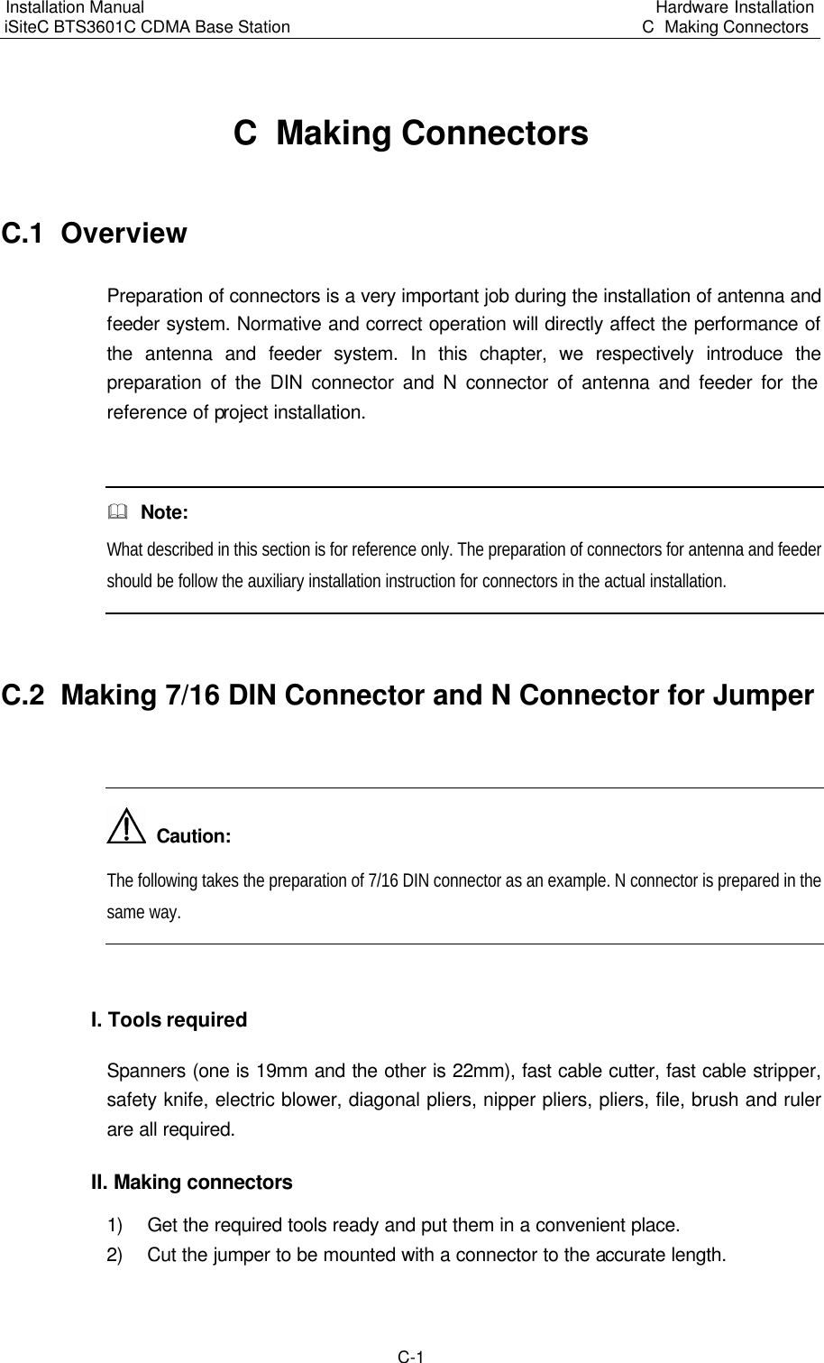
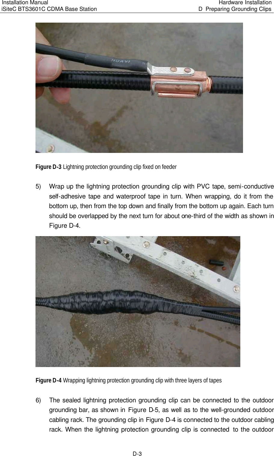
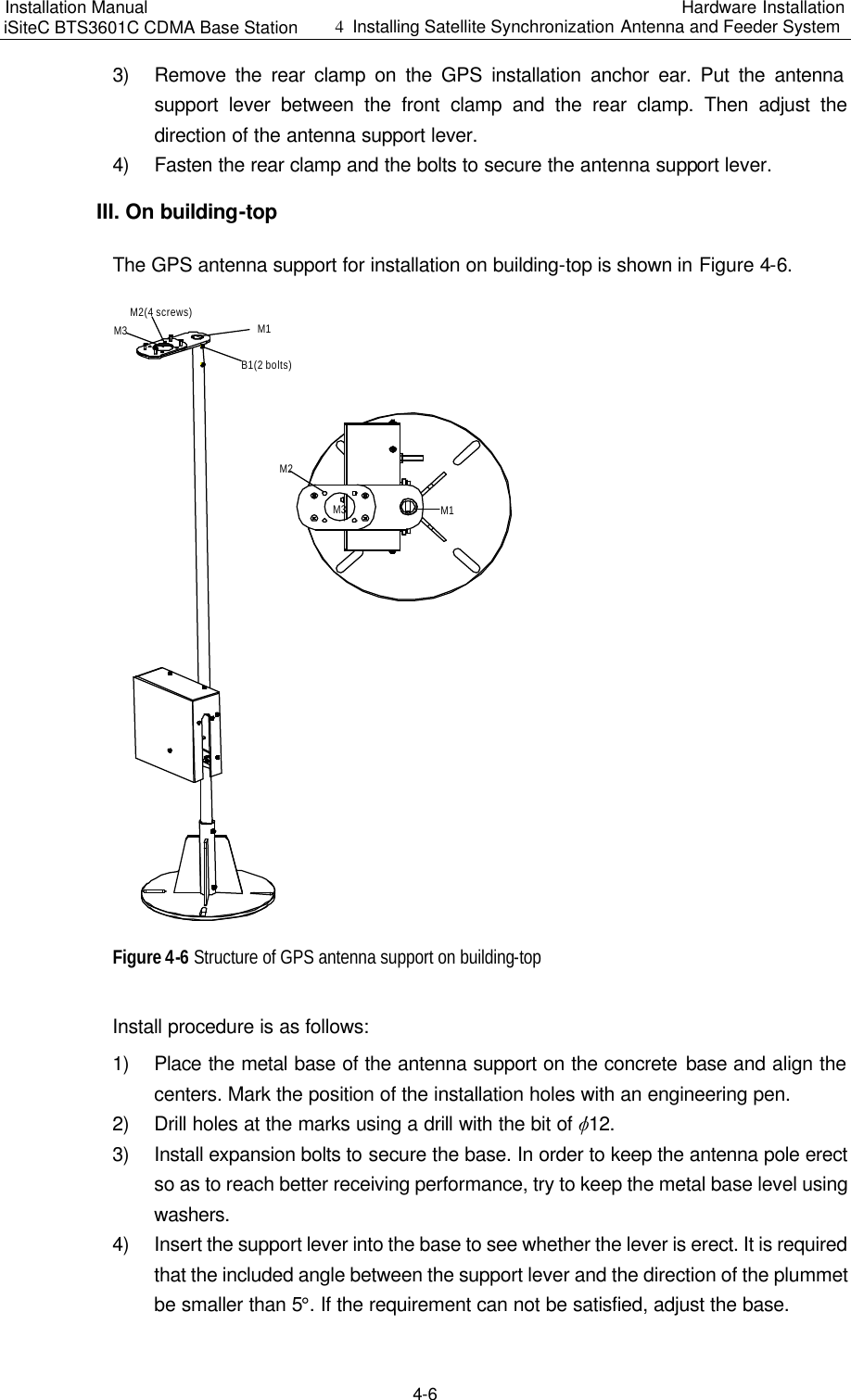
![Installation Manual iSiteC BTS3601C CDMA Base Station Software Installation & System Commissioning 0错误 表格结果无效 3-5 Click , the shortcut icon of Execute Command, to add the software loading information of the corresponding board. 3) Downloading software Run the remote maintenance console software (AirBridge cBSS Client), and select BTS Management in the command tree. Select Mini-BTS Management\Mini-BTS Loading Management\Download BTS Software or Data Operation (MICRO>DLD BTSSW). Click , the shortcut icon of command Create Input Interface, and input the following: l [BTS Name]: Input the name of the BTS to be downloaded with software (this entry may be omitted); l [BTS ID]: Input the ID of the BTS to be downloaded with the software; l [Software Activation Mode]: Select the activation mode for the software to be downloaded; l [Object Type]: Select the type of the object to which the software is to be downloaded; l [Software Type]: Select the type of the software to be downloaded; l [Software Version]: The information that is input here must be consistent with the version No. of the software whose loading information has been added in the system; l [Board ID]: Select the ID of the MTRB to be downloaded with the software. Click , the shortcut icon Execute Command, to download the software for the corresponding board. If the software activation mode is set to be "Automatic Activation", the software will be activated automatically after the downloading. V. Activation of BTS3601C software Run the remote maintenance console software (AirBridge cBSS Client), and select BTS Management in the command tree. Select Mini-BTS Management\Mini-BTS Loading Management\Activate Mini-BTS Software/Configuration (MICRO>ACT BTSSW). Click , the shortcut icon of command Create Input Interface, and input the following:](https://usermanual.wiki/Huawei-Technologies/BTS3601C-800.Users-Manual-2/User-Guide-469343-Page-53.png)
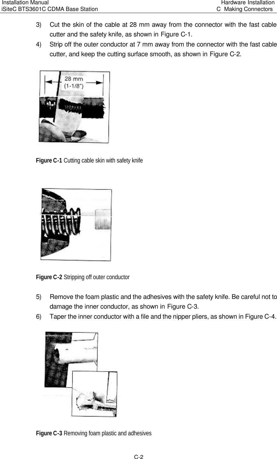
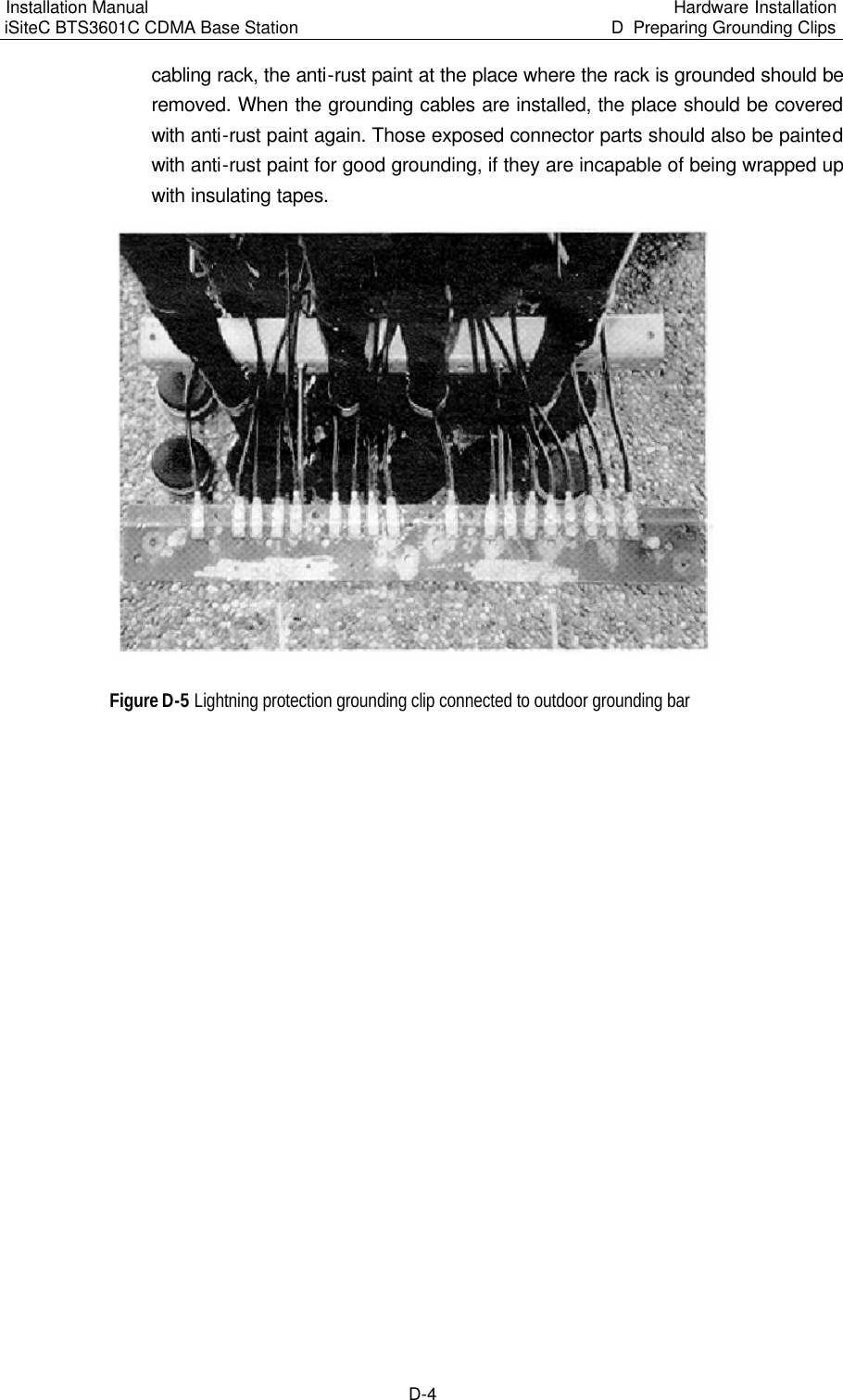
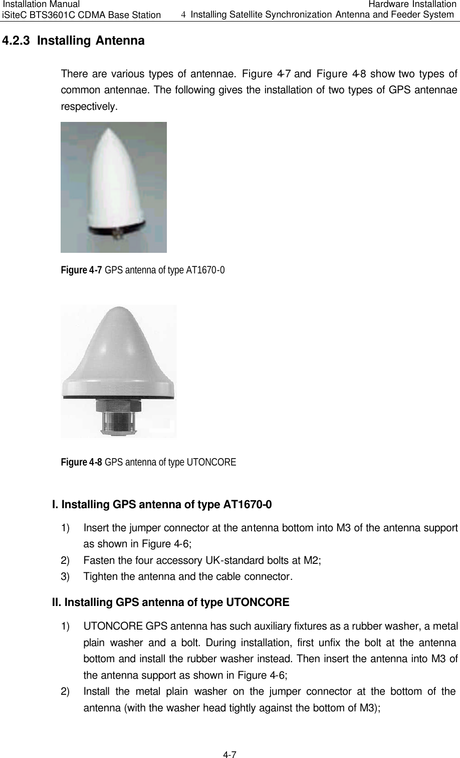
![Installation Manual iSiteC BTS3601C CDMA Base Station Software Installation & System Commissioning 0错误 表格结果无效 3-6 [BTS Name]: Input the name of BTS whose software is to be activated (this entry may be omitted); [BTS ID]: Input the ID of the BTS whose software is to be activated; [Object Type]: Select the type of the object whose software is to be activated; [Software Type]: Select the type of the software to be activated; [Software Version]: Input the version No. of the software to be activated; [Board ID]: Select the ID of the corresponding board. Click , the shortcut icon of Execute Command, to activate the corresponding board software/data. & Note: The activation of the software can be conducted automatically by the system if the [Software Activation Mode] is set as "Automatic" during the setup to download the software. VI. Uploading of BTS3601C configuration data Run the remote maintenance console software (AirBridge cBSS Client), and select BTS Management in the command tree. Select Mini-BTS Management\Mini-BTS Loading Management\Upload BTS Data Operation (MICRO>ULD BTSCFG). Click , the shortcut icon of command Create Input Interface, and input the following: [BTS Name]: Input the name of BTS whose configuration data is to be uploaded (this entry may be omitted); [BTS ID]: Input the ID of the BTS whose data is to be uploaded; [Object Type]: Select the type of the object whose data is to be uploaded. Click , the shortcut icon of command Execute Command, to upload the corresponding BTS3601C configuration data.](https://usermanual.wiki/Huawei-Technologies/BTS3601C-800.Users-Manual-2/User-Guide-469343-Page-54.png)
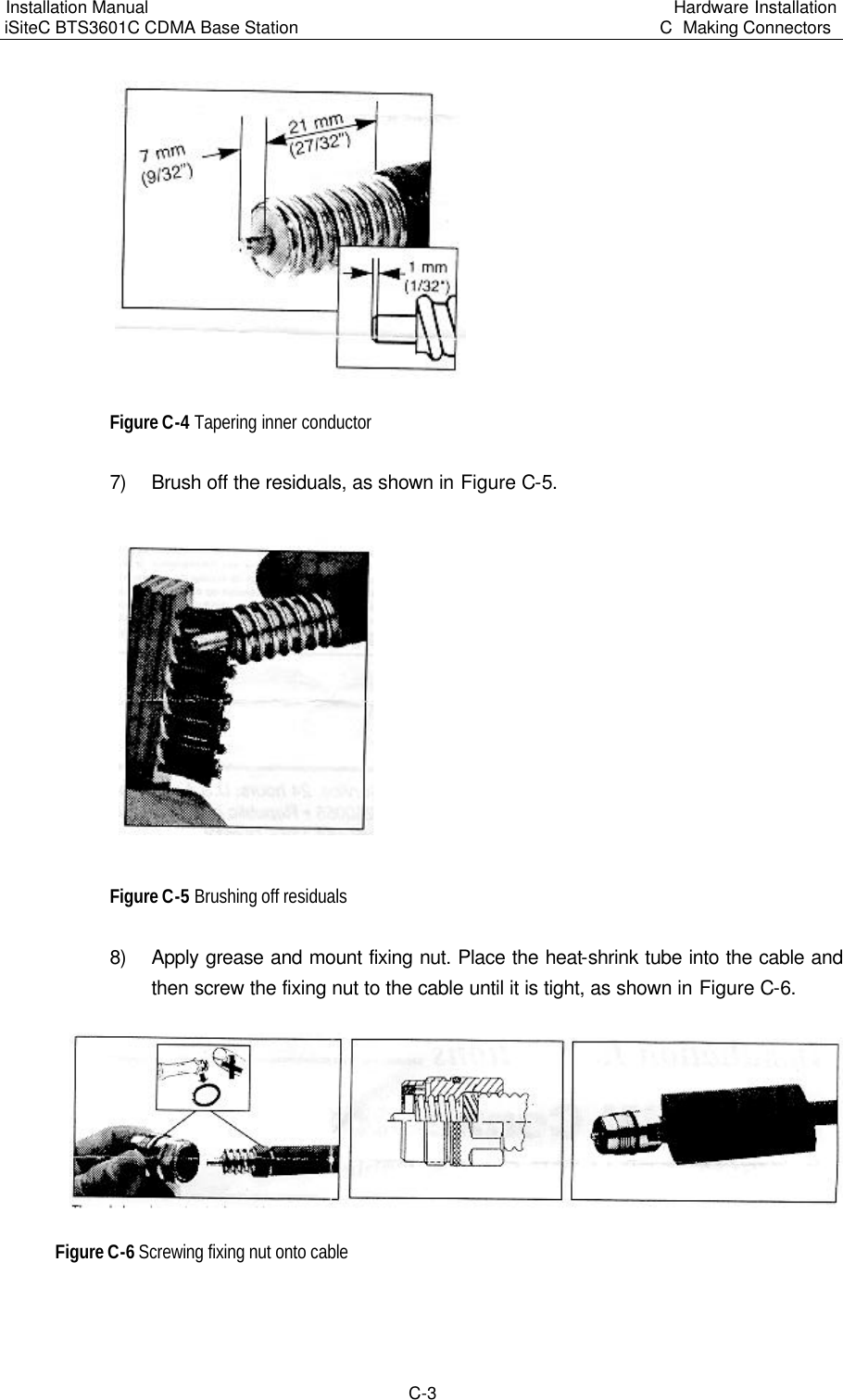
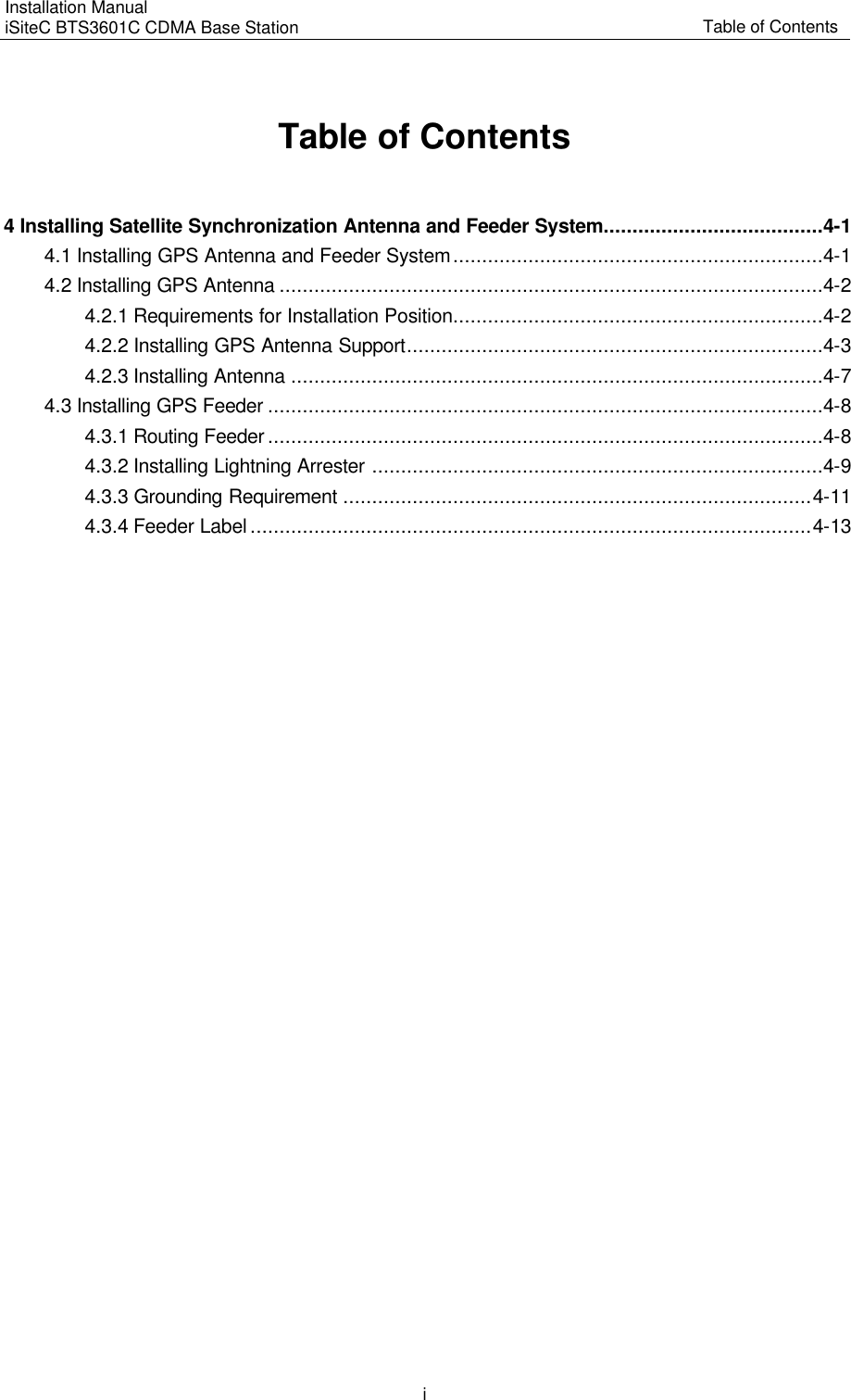
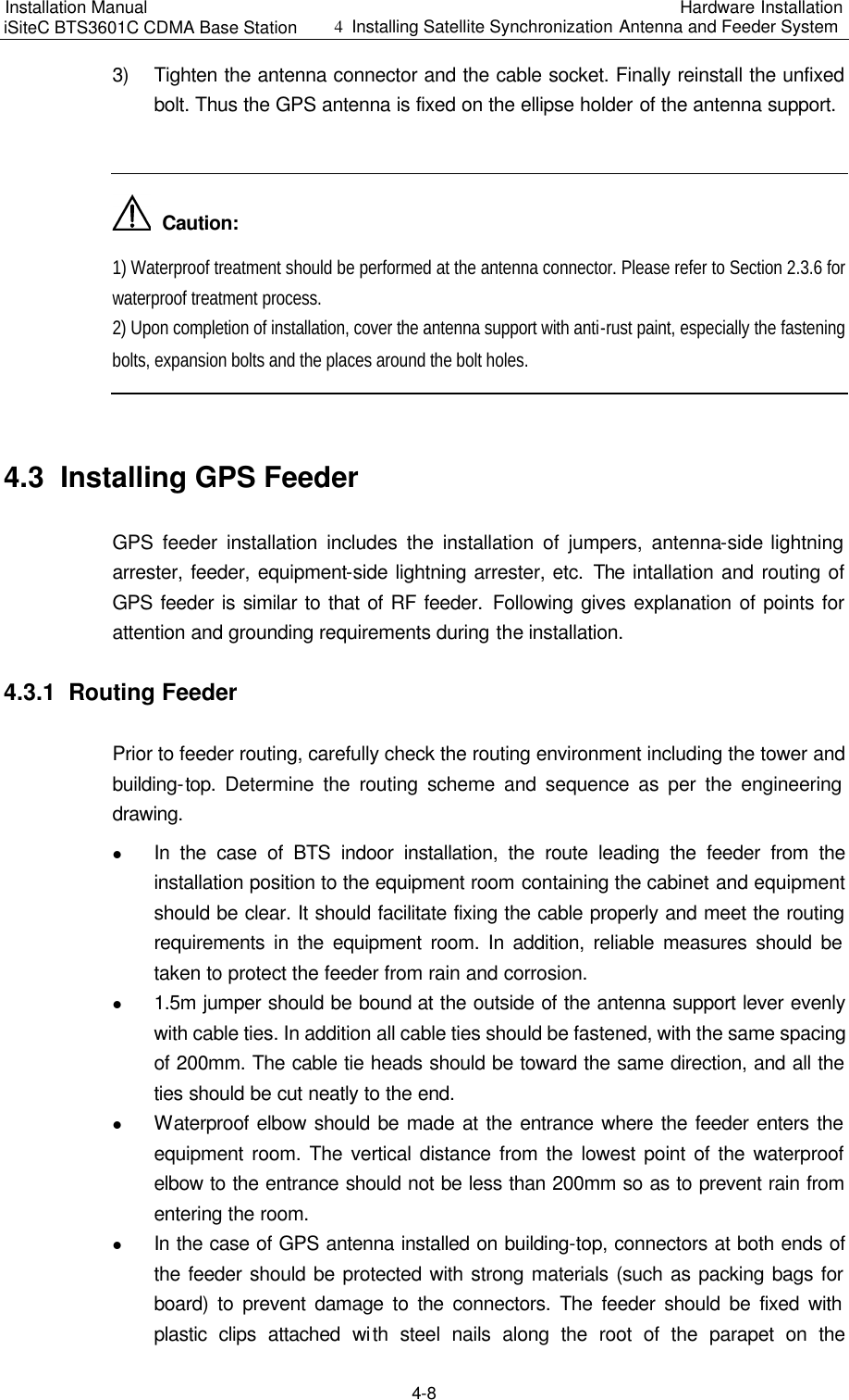
![Installation Manual iSiteC BTS3601C CDMA Base Station Software Installation & System Commissioning 0错误 表格结果无效 3-7 If this operation is successful, BTS3601C will operate by FTP to upload the configuration information of the specified version to the remote BAM, and save it under the file loading path designated when adding the software loading information. 3.3.3 Verifying the Software Version You can execute a query command through the remote/local maintenance console to get the version information of the running software on BTS3601C boards. I. Get the version information of board software through the remote maintenance console Run the remote maintenance console software (AirBridge cBSS Client), and select BTS Management in the command tree. Select Mini-BTS Management\Mini-BTS Equipment Management\Query Mini-BTS Board Version Information (MICRO>DSP BTSBRDVER). Click , the shortcut icon of command Create Input Interface, and input the following: [BTS Name]: Input the name of the BTS which is to be downloaded with software (this entry may be omitted); [BTS ID]: Select the ID of the BTS to be queried; [Board Type]: Select the type of the BTS board to be queried; [Board ID]: Select the ID of the BTS MTRB to be queried (if [Board Type] is selected to be Micro-bts Base-band Processing Board (MBPB), this parameter will not appear). Click , the shortcut icon of Execute Command, to get the query result of BTS board version information in the maintenance window. II. Query the board version information through the local maintenance console Start Telnet at the local maintenance console. Input the following command under the prompt character after the login: DSP BTSBRDVER:BRDTP=<MBPB>,BRDID=<0> BRDTP is the type of the board to be queried, and BRDID is the ID of the board to be queried.](https://usermanual.wiki/Huawei-Technologies/BTS3601C-800.Users-Manual-2/User-Guide-469343-Page-55.png)
![Installation Manual iSiteC BTS3601C CDMA Base Station Software Installation & System Commissioning 0错误 表格结果无效 2-3 2.2.4 Software Installation and Instructions Since Local O&M software (Ftp.exe and Telnet.exe) is self-contained by Windows9x, there is no need for extra installation. To run Ftp/Telnet, click [Start/Run] in the system menu of the computer, and input "ftp xxx.xxx.xxx.xxx"/"telnet xxx.xxx.xxx.xxx" into the dialogue box of [Run]. "xxx.xxx.xxx.xxx" is the IP address of MBPM network port. Ftp/Telnet is then started for you to log in to the MBPM. 2.3 Installing Remote O&M Software 2.3.1 Operational Environment The remote O&M software (referring to the BTS3601C Client software here) should be installed to the same computer together with BSC Client and BTS3612 Client. 2.3.2 Conditions 1) Make sure the computer is installed with only the software necessary for the system. Otherwise, there may be operational conflicts that may affect the normal operation of the Client software. Moreover, make sure that a nice and stable network hardware environment has been established. 2) Obtain from Huawei the complete set of installation files and read-me files, as well as a legal product serial number. 3) BTS3601C Client software should be installed only after the corresponding BSC Client and BTS3612 Client have been installed. Before installation, please make sure that the versions of the three kinds of software are consistent. 2.3.3 Software Installation and Instructions The BSC Client and BTS3612 Client (both are of the matching versions) should have been installed first (for instructions, please refer to the corresponding parts in BSC/BTS3612 installation manuals). After that, to install BTS3601C Client software, the procedures include: I. Starting SETUP.EXE After inserting the installation disk into the disk drive, different alternatives are provided for: l If auto execution has been set for the system, the program will be started then. l Or, you should click [Start/Run] in the system menu and key in "SETUP" and the corresponding driver icon and path, and press <Enter>.](https://usermanual.wiki/Huawei-Technologies/BTS3601C-800.Users-Manual-2/User-Guide-469343-Page-60.png)
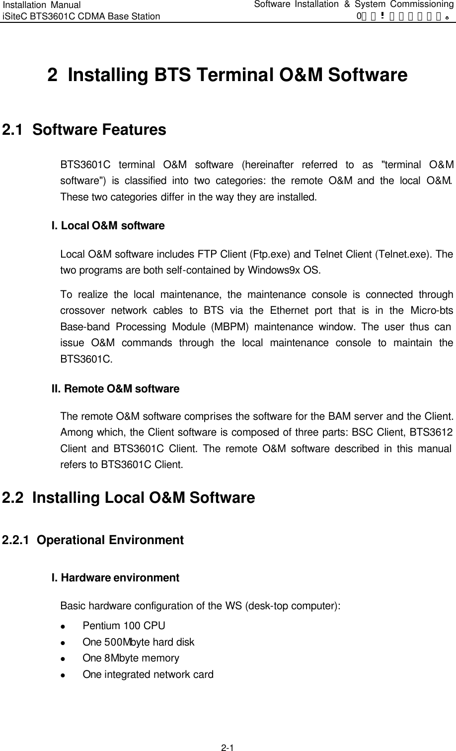
![Installation Manual iSiteC BTS3601C CDMA Base Station Software Installation & System Commissioning 0错误 表格结果无效 2-4 l You can also click [SETUP.EXE] in the Resource Manager to run the program. l You can copy the files in the installation disk to the hard disk and run them. The initial installation interface as shown in Figure 2-2 will then pop up. Figure 2-2 Initial installation interface Click <Next> to continue (or click <Cancel> to exit the installation). II. License agreement and installation instructions The [Software License Agreement] will pop up as shown in Figure 2-3. After reading it carefully, click <Yes> to accept it and continue (or <No> to exit the installation).](https://usermanual.wiki/Huawei-Technologies/BTS3601C-800.Users-Manual-2/User-Guide-469343-Page-61.png)
![Installation Manual iSiteC BTS3601C CDMA Base Station Software Installation & System Commissioning 0错误 表格结果无效 2-6 III. Confirming the installation information You are required to confirm the installation information as shown in Figure 2-5 before copying files. If you want to change the installation information, please click <Back> to return to the previous step. Otherwise, click <Next> to continue. Figure 2-5 Confirming the installation information & Note: The default installation path for BTS3601C Client software is D:\AirBridge, the same as that of BSC Client and BTS3612 Client. If the installation path of BSC/BTS3612 Client has been changed, the installation program of BTS3601C Client will automatically find the new one. IV. Completing the installation After confirming the installation information, the installation program will start copying files. In the process of file copying, the installation program will show such information including overall progress, available disk space, available memory and progress of individual file copying. Upon the completion of the installation, the window [Setup Complete] as shown in Figure 2-6 will pop up.](https://usermanual.wiki/Huawei-Technologies/BTS3601C-800.Users-Manual-2/User-Guide-469343-Page-63.png)
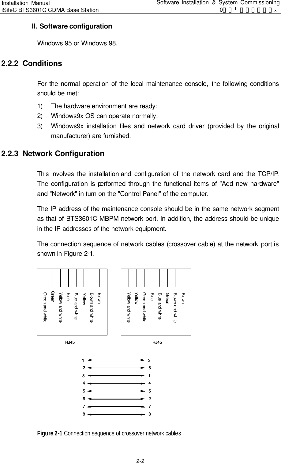
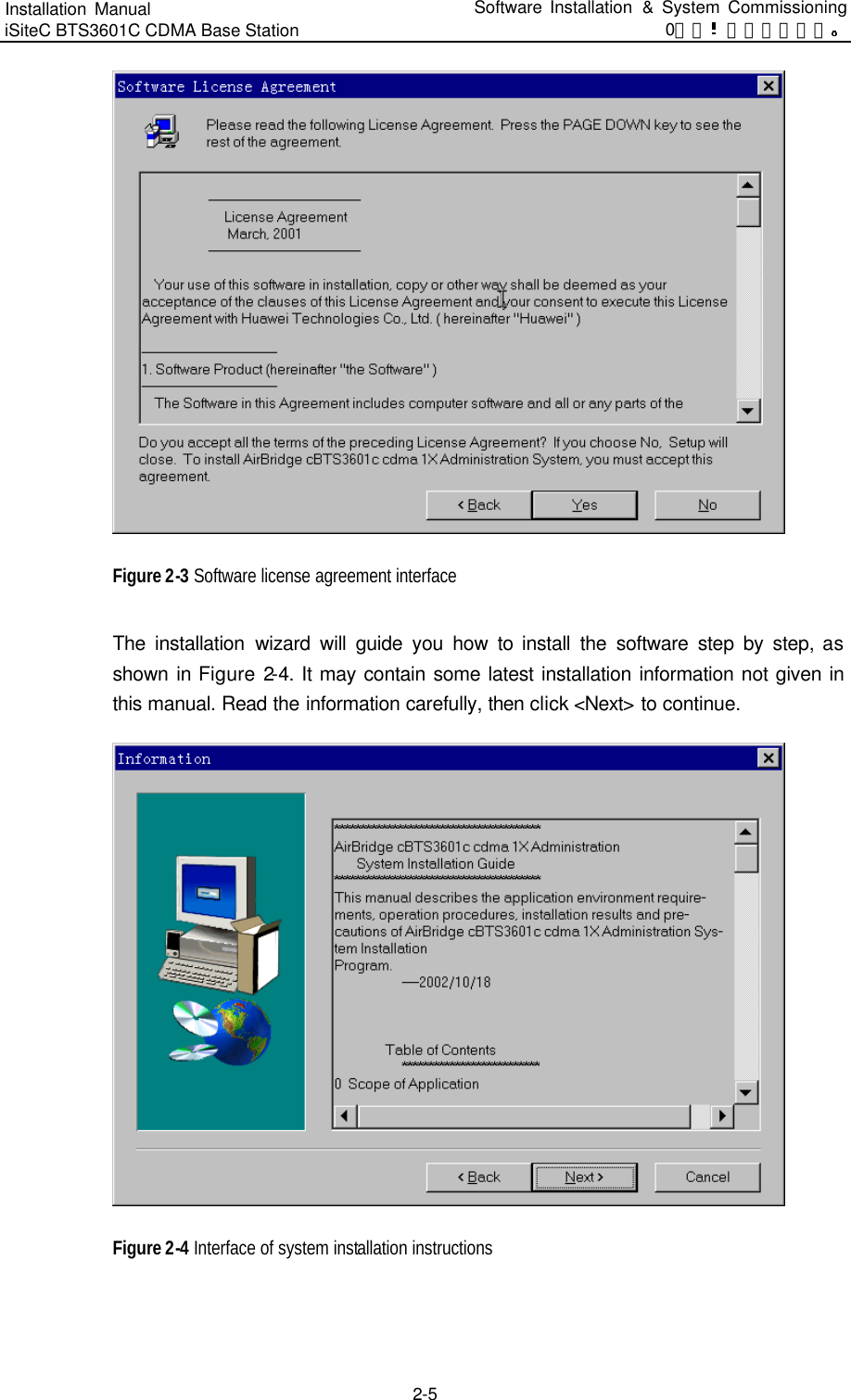
![Installation Manual iSiteC BTS3601C CDMA Base Station Software Installation & System Commissioning 0错误 表格结果无效 2-7 Click <OK>, and the system should be restarted to make the Client software valid. Figure 2-6 End of the installation That is the end of the installation of BTS3601C Client software. & Note: The above described installation procedure is the one in normal situation. If abnormality occurs at any installation procedure, please follow the system prompts. After the installation, click [Start/Program/Airbridge cBSS cdma 1X Administration System/ AirBridge cBSS Client] to start the Client software. The operation interface is shown in Figure 2-7.](https://usermanual.wiki/Huawei-Technologies/BTS3601C-800.Users-Manual-2/User-Guide-469343-Page-64.png)
![Installation Manual iSiteC BTS3601C CDMA Base Station Software Installation & System Commissioning 0错误 表格结果无效 4-5 II. Alarm processing Boards will report a message to OMU when an alarm is generated or cleared. Accordingly, OMU will set the board availability status and take related measures. OMU will report all the alarms to OMC to facilitate operators locate the fault before further measures can be taken. 4.3.3 Operation and Maintenance BTS3601C provides convenient O&M function to manage and maintain the BTS3601C equipment. The functions include loading management, configuration management, equipment management, tracing management and testing management. What follows is the description of some daily maintenance operations from the angle of OMC terminal. I. Equipment management 1) Querying the operation status of BTS3601C boards Run the remote maintenance console software (AirBridge cBSS Client), and select BTS Management in the command tree. Select Mini-BTS Management\Mini-BTS Equipment Management\Query Mini-BTS Board Status (MICRO>DSP BTSBRDSTAT). Click , the shortcut icon of command Create Input Interface, and input the following: l [BTS Name]: Input the name of the BTS (this entry may be omitted); l [BTS ID]: Select the ID of the BTS to be queried; l [Board Type]: Select the type of the BTS board to be queried; l [Board ID]: Select the ID of the BTS MTRB to be queried (when [Board Type] is selected to be MBPB, this parameter will not appear). Click , the shortcut icon of Execute command, to display the query result about the corresponding BTS board status in the maintenance window. 2) Querying the version information of BTS3601C boards Run the remote maintenance console software (AirBridge cBSS Client), and select BTS Management in the command tree. Select Mini-BTS Management\Mini-BTS Equipment Management\Query Mini-BTS Board Version Information (MICRO>DSP BTSBRDVER).](https://usermanual.wiki/Huawei-Technologies/BTS3601C-800.Users-Manual-2/User-Guide-469343-Page-71.png)
![Installation Manual iSiteC BTS3601C CDMA Base Station Software Installation & System Commissioning 0错误 表格结果无效 4-6 Click , the shortcut icon of Create Input Interface, and input the following: l [BTS Name]: Input the name of the BTS (this entry may be omitted); l [BTS ID]: Select the ID of the BTS to be queried; l [Board Type]: Select the type of the BTS board to be queried; l [Board ID]: Select the ID of the BTS MTRB to be queried (when [Board Type] is selected to be MBPB, this parameter will not appear). Click , the shortcut icon of Execute command , to display the query result of BTS board version information in the maintenance window. 3) Resetting BTS3601C boards Boards can be reset through the BTS3601C remote/local O&M console. OMU issues the board resetting command to the corresponding board. In receipt of the command, the board will reset itself, send the reset report message to and wait for the initialization data from OMU. Board reset will affect the system operation status. It is recommended that the user use it prudently. The method to reset BTS3601C boards on the remote BTS3601C maintenance console is as follows: Run the remote maintenance console software (AirBridge cBSS Client), and select BTS Management in the command tree. Select Mini-BTS Management\Mini-BTS Equipment Management\Reset Mini-BTS Board (MICRO>RST BTSBRD). Click , the shortcut icon of command Create Input Interface, and input the following: l [BTS Name]: Input the name of the BTS (this entry may be omitted); l [BTS ID]: Select the ID of the BTS to be managed. l [Board Type]: Select the type of the BTS board to be reset. l [Board ID]: Select the ID of the BTS MTRB to be reset (when [Board Type] is selected to be MBPB, this parameter will not appear); l [Level of resetting]: Select the level of the reset. Click , the shortcut icon of Execute command, to reset the corresponding BTS board. II. Tracing management 1) Starting BTS3601C resource tracing](https://usermanual.wiki/Huawei-Technologies/BTS3601C-800.Users-Manual-2/User-Guide-469343-Page-72.png)
![Installation Manual iSiteC BTS3601C CDMA Base Station Software Installation & System Commissioning 0错误 表格结果无效 4-7 Run the remote maintenance console software (AirBridge cBSS Client), and select BTS Management in the command tree. Select Mini-BTS Management\Mini-BTS Tracing Management\Start Mini-BTS Resource Tracing (MICRO>STR BTSRESTRC). Click , the shortcut icon of command Create Input Interface, and input the following: l [BTS Name]: Input the name of the BTS (this entry may be omitted); l [BTS ID]: Select the ID of the BTS to be managed; l [Board Type]: Select the type of the board to be traced; l [Board ID]: Select the ID of the BTS MTRB to be traced (when [Board Type] is selected to be MBPB, this parameter will not appear); l [Resource Type]: Select the type of the resource to be traced. Click , the shortcut icon of Execute command, to display the tracing result of the corresponding BTS3601C board resource in the maintenance window. 2) Stopping BTS3601C resource tracing Run the remote maintenance console software (AirBridge cBSS Client), and select BTS Management in the command tree. Select Mini-BTS Management\Mini-BTS Tracing Management\Stop Mini-BTS Resource Tracing (MICRO>STP BTSRESTRC). Click , the shortcut icon of Create Input Interface, and input the following: l [BTS Name]: Input the name of the BTS (this entry may be omitted); l [BTS ID]: Select the ID of the BTS to be managed; l [Board Type]: Select the type of the board no longer to be traced. l [Board ID]: Select the ID of the BTS MTRB no longer to be traced (when [Board Type] is selected to be MBPB, this parameter will not appear); l [Resource Type]: Select the type of the resource no longer to be traced. Click , the shortcut icon of Execute command, to stop tracing the corresponding BTS3601C board resource. III. Test management 1) Starting BTS3601C loopback test The loopback test can be conducted on the BTS3601C remote maintenance console to check the status of the BTS3601C MBPB-MTRB OML. The following describes the method to perform the loopback test.](https://usermanual.wiki/Huawei-Technologies/BTS3601C-800.Users-Manual-2/User-Guide-469343-Page-73.png)
![Installation Manual iSiteC BTS3601C CDMA Base Station Software Installation & System Commissioning 0错误 表格结果无效 4-8 Run the remote maintenance console software (AirBridge cBSS Client), and select BTS Management in the command tree. Select Mini-BTS Management\Mini-BTS Test Management\Start Mini-BTS Loopback Test (MICRO>STR BTSLPBACKTST). Click , the shortcut icon of Create Input Interface, and input the following: l [BTS Name]: Input the name of the BTS (this entry may be omitted); l [BTS ID]: Select the ID of the BTS to be managed; l [Board ID]: Select the number of the MTRB to be tested. l [Test Type]: Select the type of the loopback to be conducted. l [Time of Loopback]: Select or input the number of times that the loopback test will be conducted. Click , the shortcut icon of command Execute command, to start the loopback test for the corresponding BTS3601C board. 2) Stopping BTS3601C loopback test Run the remote maintenance console software (AirBridge cBSS Client), and select BTS Management in the command tree. Select Mini-BTS Management\Mini-BTS Test Management\Stop Mini-BTS Loopback Test (MICRO>STP BTSLPBACKTST). Click , the shortcut icon of command Create Input Interface, and input the following: l [BTS Name]: Input the name of the BTS (this entry may be omitted); l [BTS ID]: Select the ID of the BTS to be managed; l [Board ID]: Select the number of the MTRB on which the loopback test is to be stopped. l [Test Type]: Select the type of the loopback to be stopped. Click , the shortcut icon of Execute command, to stop the loopback test on the corresponding BTS3601C board. 3) Starting BTS3601C E1 test BTS3601C E1 test can be conducted on the remote O&M console to check the BSC-BTS physical transmission link, so as to locate the transmission fault or evaluate the quality of the transmission link. Run the remote maintenance console software (AirBridge cBSS Client), and select BTS Management in the command tree.](https://usermanual.wiki/Huawei-Technologies/BTS3601C-800.Users-Manual-2/User-Guide-469343-Page-74.png)
![Installation Manual iSiteC BTS3601C CDMA Base Station Software Installation & System Commissioning 0错误 表格结果无效 4-9 Select Mini-BTS Management\Mini-BTS Test Management\Start Mini-BTS E1 Test (MICRO>STR BTSE1TST). Click , the shortcut icon of Create Input Interface, and input the following: l [BTS Name]: Input the name of the BTS (this entry may be omitted); l [BTS ID]: Select the ID of the BTS to be managed; l [Test Type]: Select the type of the loopback to be conducted; l [Duration of Test (min)]: Select or input the time that the loopback test will last. This is an optional parameter. By default: 5min. Click , the shortcut icon of Execute command , to start the loopback test on the corresponding BTS3601C E1 link. 4.4 Call Function Test After the hardware installation, check, software installation and basic commissioning, the user should start the BTS3601C overall function test: service function test. 4.4.1 Test Equipment I. Abis interface signaling monitoring Connect the signaling protocol tester (such as K1205 and MA10) to the E1 cables between BSC and BTS. Set the protocol stack as Abis interface, and select the timeslot to be monitored according to BSC configuration. If no signaling tester is available, the OMC interface tracing function also works. II. Call generator It is used to simulate multi-user call setup. III. Test MS It is used to test the service functions. 4.4.2 Preparations for Service Function Test Before the test, make the following preparations: 1) Make sure that BSC and BTS3601C are properly connected. BSC and BTS3601C can be connected via E1/T1 or optical fiber. Make sure that the connection is correct before the system is powered on.](https://usermanual.wiki/Huawei-Technologies/BTS3601C-800.Users-Manual-2/User-Guide-469343-Page-75.png)