Huawei Technologies BTS3601C-800 CDMA Base Station User Manual 2
Huawei Technologies Co.,Ltd CDMA Base Station Users Manual 2
Contents
- 1. Users Manual 1
- 2. Users Manual 2
- 3. Users Manual 3
Users Manual 2

Installation Manual
iSiteC BTS3601C CDMA Base Station Table of Contents
i
Table of Contents
5 Installation Check ..............................................................................................................5-1
5.1 Overall Check............................................................................................................5-1
5.1.1 Checking Equipment Installation .......................................................................5-1
5.1.2 Checking Cable Connection..............................................................................5-1
5.1.3 Checking Lightning Protection Grounding ..........................................................5-1
5.2 Power-on Check........................................................................................................5-3
5.3 Checking Environment Condition ................................................................................5-3
5.4 System Commissioning..............................................................................................5-3

Installation Manual
iSiteC BTS3601C CDMA Base Station Hardware Installation
错误 未找到引用源 错误 未找到引用源
5-1
5 Installation Check
Upon completion of all hardware installation, check the installation including the
following aspects: overall check, power-on check, environment condition check and
system commissioning.
5.1 Overall Check
5.1.1 Checking Equipment Installation
l All the equipment should be steady and neat in appearance when installed.
l All the bolts and nuts are fastened. And plain washers and spring washers are
applied under all the nuts with the plain washer under the spring washer.
l There should be no missing or damaged parts on the equipment, and all the
cables should be intact.
l The rack interior should be cleaned. Fingerprints and smudges left during the
installation should be cleaned. There should be no dust in the rack.
5.1.2 Checking Cable Connection
l Power cables should be well connected. The connector should not be loose or
damaged. And there should be no scratch or fissure on the power cable skin.
l Check whether the contact of the grounding cable is good.
l Check whether the trunk cable connections are secure and correct.
l All the cables should be secure. Do not over-strain the cables running round the
corner. Cables and fibers should run in straight and smooth courses without any
cross. Cables and fibers in the same direction should be bundled up. The cable
layout should be neat and tidy with the same bundling space. Signal cables cannot
be bundled with power cables and grounding cables.
l There should be no damage to the skin of all the cables.
5.1.3 Checking Lightning Protection Grounding
I. Checking outdoor grounding
Outdoor grounding check includes the following aspects:
l Outdoor grounding bar should be connected to the counterpoise with grounding
bus. DO NOT connect the outdoor grounding bus to the grounding flat steel of the
feeder lightning arrester.

Installation Manual
iSiteC BTS3601C CDMA Base Station Hardware Installation
错误 未找到引用源 错误 未找到引用源
5-2
l Check whether there is good electrical connection between the UPS shell and the
UPS external box via screws. UPS external box should be grounded.
l Check whether the protection grounding cable of AC lightning protection box or
IAFB is directly connected to the protection grounding bar. Make sure the
grounding cable is shorter than 1m.
l The AC power cable from the exterior to the BTS should be directly connected to
the AC lightning protection box (when AC lightning protection box is available) or
to the IAFB (when AC lightning protection box is unavailable). It is not allowed to
connect the external power cable to the power distribution terminal in the work box
first and then to the AC lightning protection box.
l When E1 cable is used for signal transmission of the BTS, if the E1 cable from the
exterior to the BTS is coaxial cable with metal shell (provided by the user), its
metal shell should be grounded with grounding clip. The grounding cable from the
grounding clip should be directly connected to the protection grounding bar
instead of to the grounding bar of the IAFB.
l In BTS outdoor tower installation mode, the shielding covering of the BTS coaxial
feeder should be grounded at the tower-top and the front end connecting the BTS.
The grounding cable should be connected to the tower body nearby. The
protection grounding bar should have separate grounding donwlead that is not
insulated from the tower body.
l When the feeder is not shorter than 60m, the shielding covering of the coaxial
feeder should be grounded at the middle of the tower body.
II. Checking indoor grounding
Indoor grounding check includes the following aspects:
l In BTS indoor installation, there should be indoor grounding bar and outdoor
grounding bar that should be led into the counterpoise separately instead of being
connected in series directly with grounding cables.
l The grounding cable at the point where the feeder enters the feeder window is
connected to the outdoor grounding bar in the direction from the antenna to the
BTS.
l The AC lightning protection box provides separate grounding cable to connect to
the indoor grounding bar. The grounding cable from the AC lightning protection
box or from the IAFB to the indoor grounding bar should be shorter than 1m.
l Check whether there is good electrical connection between the UPS shell and the
UPS external box via screws. UPS external box should be grounded.
l When E1 cable is used for signal transmission of the BTS, if the E1 cable from the
exterior to the BTS is coaxial cable with metal shell (provided by the user), its
metal shell should be grounded with grounding clip. The grounding cable from the
grounding clip should be directly connected to the indoor grounding bar instead of
to the grounding bar of the IAFB.

Installation Manual
iSiteC BTS3601C CDMA Base Station Hardware Installation
错误 未找到引用源 错误 未找到引用源
5-3
l The shielding covering of the coaxial feeder should be well grounded at the
tower-top, tower-bottom and the outside of the entrance to the equipment room.
When the feeder is not shorter than 60m, the shielding covering of the coaxial
feeder should be grounded at the middle of the tower body.
l The outdoor grounding bar and indoor protection grounding bar should share the
counterpoise of the equipment room. The outdoor grounding bar should not be
connected to the tower counterpoise for grounding.
l The feeder skin should be grounded after the feeder enters the equipment room.
The grounding cable from the feeder skin should be directly connected to the
indoor grounding bar.
5.2 Power-on Check
1) Check whether the voltage of the power supply is normal (normal voltage range:
150VAC~300VAC). If it is normal, turn on the power switch of the BTS and check
whether the indicators on the power supply module of the BTS are normal. Please
refer to User Manual for indicator descriptions.
2) Observe the running of boards and modules. Cut off the power supply immediately
in case of any exception. Power on all the boards and modules after the fault is
removed.
5.3 Checking Environment Condition
1) There should be no sundries inside or on top of the sun-shading cover. The cover
should be clean without any smudge or fingerprint.
2) There should be no redundant tape or cable tie on the cable.
3) There should be no tape, cable tie head, waste paper, or packing bag around the
BTS.
4) All the things around the BTS should be clean and neat in their original
appearance.
5.4 System Commissioning
After the BTS is powered on, if the indicators of all the modules are normal, system
commissioning should be performed by starting some basic operations and
maintenance and function test. The following briefs the items of system commissioning:
1) Location update flow
2) MO call flow
3) MT call flow
4) Handover flow
5) MO SM flow
6) MT SM flow
7) MO packet data flow

Installation Manual
iSiteC BTS3601C CDMA Base Station Hardware Installation
错误 未找到引用源 错误 未找到引用源
5-4
8) MS packet data flow test (downlink traffic rate).
&
Note:
System commissioning items can be determined as per the specific situation at the site. The above is the
system commissioning item list. For details, please refer to relevant engineering documents.

Installation Manual
iSiteC BTS3601C CDMA Base Station Table of Contents
i
Table of Contents
A Installing IAFB.................................................................................................................. A-1
A.1 Installation Flow ....................................................................................................... A-1
A.2 Wall Installation ........................................................................................................ A-1
A.3 Metal Mast Installation .............................................................................................. A-4
A.4 Pole Installation........................................................................................................ A-5
A.5 Installation Check..................................................................................................... A-6
B Requirements for Antenna Isolation ................................................................................B-1
C Making Connectors..........................................................................................................C-1
C.1 Overview.................................................................................................................C-1
C.2 Making 7/16 DIN Connector and N Connector for Jumper ...........................................C-1
C.3 Making 7/16 DIN Connector and N Connector for 7/8 Feeder ......................................C-5
D Preparing Grounding Clips ..............................................................................................D-1
D.1 Overview.................................................................................................................D-1
D.2 Preparation Process.................................................................................................D-1
Installation Manual
iSiteC BTS3601C CDMA Base Station Hardware Installation
A Installing IAFB
A-1
A Installing IAFB
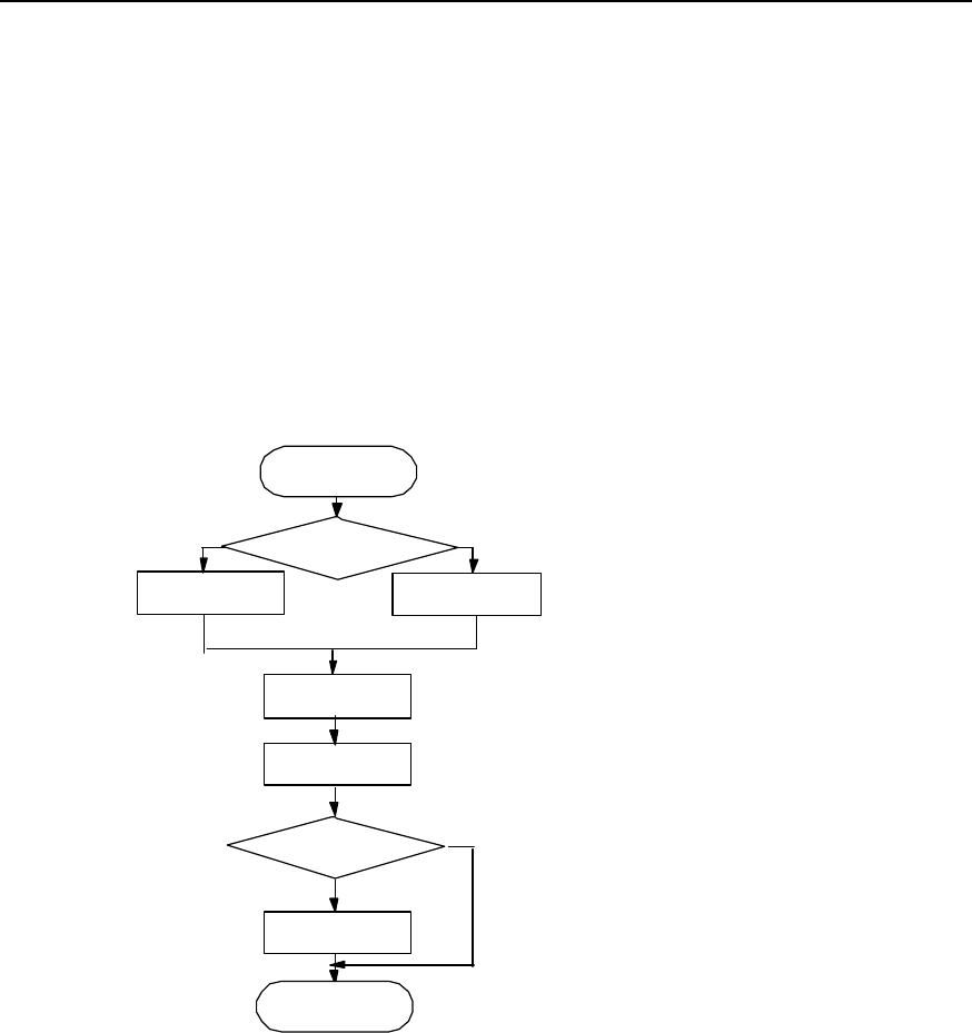
There are 3 installation modes for IAFB: Wall installation, metal mast installation
(v60~v114) and pole installation (v150~v350).
A.1 Installation Flow
Figure A-1 is the installation flow of IAFB.
Install IAFB
Install sun-shading
cover
Wall installation Metal mast or pole
installation
Install
fastener
Fit bolt
Install hanger
Outdoor
installation?
Y
N
Select installation
mode
Start
End
Figure A-1 IAFB installation flow
A.2 Wall Installation
The wall installation procedure of IAFB is as follows:
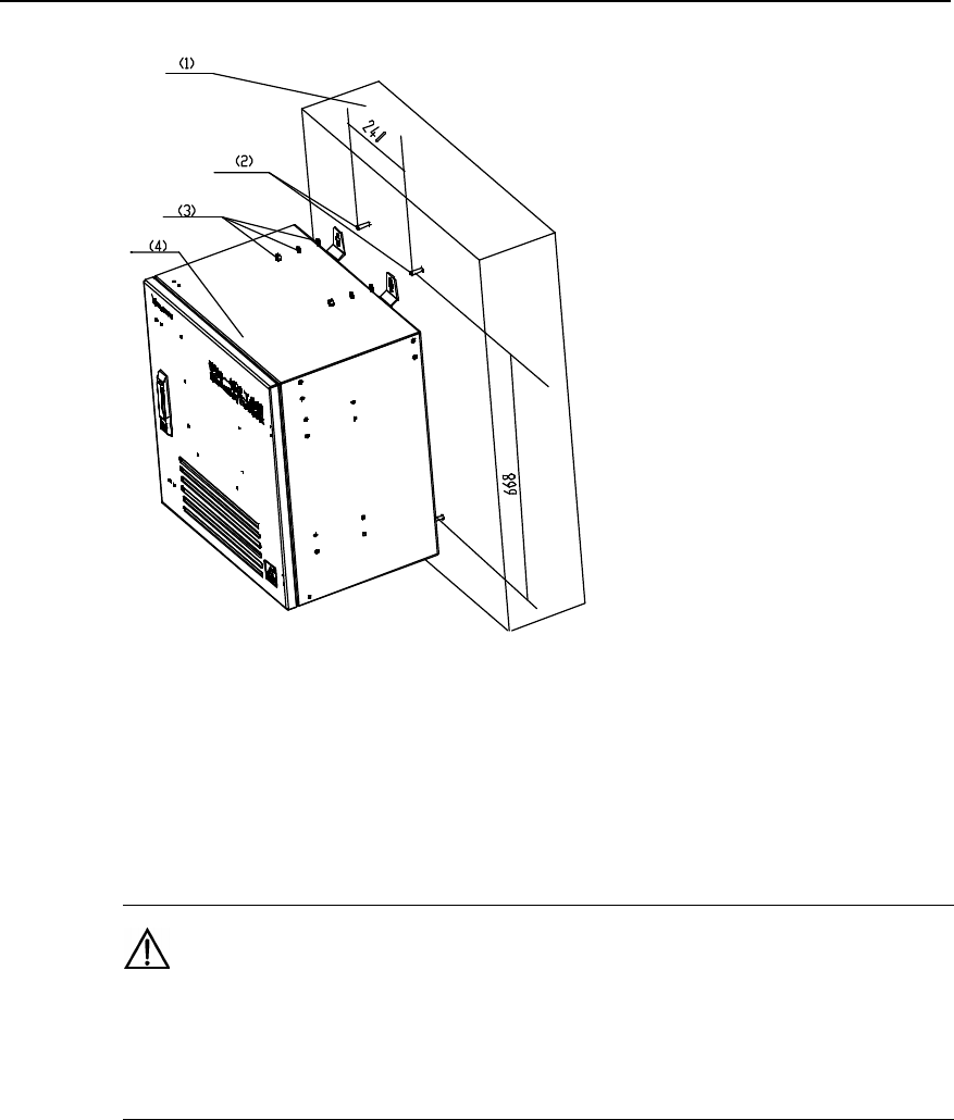
1) Determine a proper installation position on the wall. Mark it with a pencil as the
hole for bolt. The hole is the key position for bracket installation, as shown in
Figure A-2.
Installation Manual
iSiteC BTS3601C CDMA Base Station Hardware Installation
A Installing IAFB
A-2
(1) Wall (2) M8%80 exploded expansion bolt (3) Bolt, plain washer, spring washer (4) Box
Figure A-2 Fixing bolts
2) Drill a hole with the drill bit of v10mm at the mark for the bolts, Then mount the
exploded expansion M8%80 bolt.
Caution:
The depth of the hole is 50mm~60mm. It cannot be too deep; otherwise, the installation may be affected by
the part of the expansion bolt extended outside the wall. Neither can it be too shallow, otherwise it may
affect the reliability of the BTS.
3) Determine the other three holes with a plumb line and a ruler and mark them with a
pencil.
4) The procedure to drill holes and install the expansion bolts is similar to that
mentioned above.
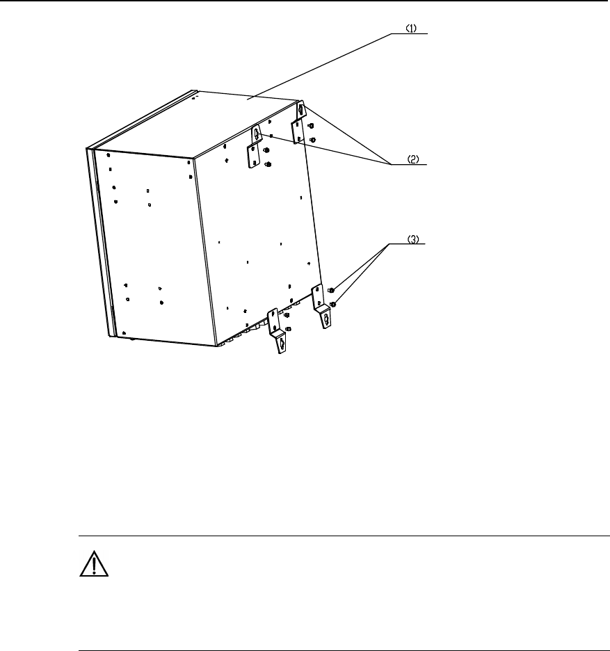
5) Use combination screw M6%12 to mount the 4 hangers on the back of the box, as
shown in Figure A-3.
Installation Manual
iSiteC BTS3601C CDMA Base Station Hardware Installation
A Installing IAFB
A-3
(1) Box (2) Hanger (3) M6%12 bolt
Figure A-3 Installing hanger
6) Mount the hangers of IAFB aiming at the four bolts. Mount plain washer, spring
washer and nut on the bolt. Then fasten the nut clockwise with an adjustable
wrench to fix the bracket on the wall.
Caution:
The length of the bolt outside the wall should be about 20mm. And the washer should be mounted before
the nut is fastened.
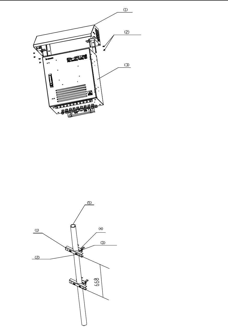
7) The installation of sun-shading cover is shown in Figure A-4. It is fixed with
M12%16 bolt.
Installation Manual
iSiteC BTS3601C CDMA Base Station Hardware Installation
A Installing IAFB
A-4
(1) Sun-shading cover (2) M12%16 bolt (3) Box
Figure A-4 Installing sun-shading cover
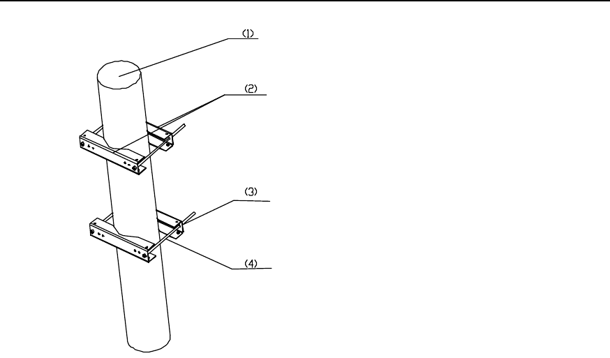
A.3 Metal Mast Installation
The installation procedure of IAFB metal mast is as follows:
1) Mount the beam and fastener to the steel pipe with M10 bolt and nut. The pipe is
between the beam and the fastener. Then fasten the bolt and nut. See Figure A-5.
(1) Beam (2) M10 bolt (3) Plain washer, spring washer, nut (4) Fastener (5) Steel pipe
Figure A-5 Installing beam and fastener
Installation Manual
iSiteC BTS3601C CDMA Base Station Hardware Installation
A Installing IAFB
A-5
2) Lean the box of IAFB on the beam and let M8%25 bolt go through the hanger of
IAFB. Then fasten the IAFB to the beam. See Figure A-6.
(1) M8%25 bolt (2) Spring washer (3) Plain washer (4) Beam
Figure A-6 Fixing IAFB
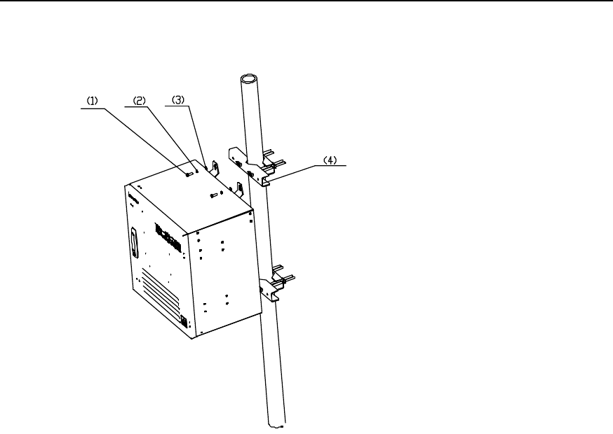
A.4 Pole Installation
The installation procedure of IAFB pole is as follows:
1) Lean the fastener to the pole and fasten the beam to let the pole be in the middle of
the pole. Then fasten the beam with bolt and nut. Refer to Figure A-7 below.
Installation Manual
iSiteC BTS3601C CDMA Base Station Hardware Installation
A Installing IAFB
A-6
(1) Pole (2) Fastener (3) Plain washer, spring washer, nut (4) M12 bolt
Figure A-7 Fixing fastener
2) Fix the IAFB to the fastener with M8%25 bolt. Its installation procedure is similar to
that on metal mast. See Figure A-6.
A.5 Installation Check
After all the parts are installed, check the installation in the following aspects: parts
installation overal check, BTS power-on check and environment check.
I. Overall Check
As a review on the whole foregoing installation process, the overall check includes the
following items:
1) Fixation check
The IAFB installed should satisfy the following requirements:
l The IAFB should be secure with neat appearance.
l All the bolts and nuts are fastened with plain washer and spring washer mounted
in correct sequence.
l There should be no missing or damaged parts, and all the cables should be intact.
l The IAFB should be clean without any smudge, fingerprint or dust.
2) Cable connection check
l Power cables should be well connected. The plugs should not be loose or
damaged. And there should be no scratch or fissure on the power cable shell.
l Check whether the contact of the grounding cables is good.

Installation Manual
iSiteC BTS3601C CDMA Base Station Hardware Installation
A Installing IAFB
A-7
l All the cables should be secure. Do not over-strain the cables running round the
corner. Cables and fibers should run in straight and smooth courses without any
cross. Cables and fibers in the same direction should be bundled up. The cable
layout should be neat and tidy with the same bundling space.
l There should be no damage to the shell of all the cables.
II. Environment condition check
1) There should be no sundries inside or on top of the sun-shading cover. The cover
should be clean without any smudge or fingerprint.
2) There should be no redundant tape or cable tie on the cable.
3) There should be no tape, cable tie head, waste paper, or packing bag around the
IAFB.
4) All the things around the BTS should be clean and neat in their original
appearance.
III. Power-on check
Open the door of the IAFB and check whether the voltage of the power supply is normal.
If ther power switch is turned on normally, test with the multimeter whether the output
voltage is normal.

Installation Manual
iSiteC BTS3601C CDMA Base Station Hardware Installation
B Requirements for Antenna Isolation
B-1
B Requirements for Antenna Isolation
I. Requirements for isolation of omni antenna
Based on the conditions that antenna gain is 10dBi and isolation is 30dB, the spacing
between antennae is required as follows:
l When antennae are installed horizontally, the horizontal spacing between transmit
(TX) antenna and receive (RX) antenna should not be less than 5.3m.
l When antennae are installed vertically, the vertical spacing between TX antenna
and RX antenna should not be less than 0.2m.
l According to the requirements for diversity receiving of omni RX antenna, the
horizontal spacing between RX antennae should not be less than 4m.
II. Requirements for isolation of directional antenna
1) Single polarization antenna
Based on the conditions that antenna gain is 15dBi, isolation is 30dB and half-power
angle is 65°, the spacing between antennae is required as follows:
l When antennae are installed horizontally, the horizontal spacing between TX
antenna and RX antenna in the same sector should not be less than 3m.
l When antennae are installed vertically, the vertical spacing between TX antenna
and RX antenna in the same sector should not be less than 0.2m.
l The horizontal spacing between TX antenna and RX antenna in different sectors
should not be less than 0.2m.
l According to the requirements for diversity receiving of directional RX antenna, the
horizontal spacing between RX antennae should not be less than 4m
2) Dual polarization antenna
For dual polarization antennae, the spacing between the ports of the RX and TX
antennae is 30dB. Therefore, the horizontal spacing may not be considered during
horizontal installation. But in vertical installation, the vertical spacing between antennae
of different sectors should not be less than 0.2m.
&
Note:
The antenna isolation requirements in this section are subject to typical applications. They are for
reference only. During the actual installation, the antenna isolation should be determined by the relevant
engineering design documents.
Installation Manual
iSiteC BTS3601C CDMA Base Station Hardware Installation
C Making Connectors
C-1
C Making Connectors
C.1 Overview
Preparation of connectors is a very important job during the installation of antenna and
feeder system. Normative and correct operation will directly affect the performance of
the antenna and feeder system. In this chapter, we respectively introduce the
preparation of the DIN connector and N connector of antenna and feeder for the
reference of project installation.
&
Note:
What described in this section is for reference only. The preparation of connectors for antenna and feeder
should be follow the auxiliary installation instruction for connectors in the actual installation.
C.2 Making 7/16 DIN Connector and N Connector for Jumper
Caution:
The following takes the preparation of 7/16 DIN connector as an example. N connector is prepared in the
same way.
I. Tools required
Spanners (one is 19mm and the other is 22mm), fast cable cutter, fast cable stripper,
safety knife, electric blower, diagonal pliers, nipper pliers, pliers, file, brush and ruler
are all required.
II. Making connectors
1) Get the required tools ready and put them in a convenient place.
2) Cut the jumper to be mounted with a connector to the accurate length.
Installation Manual
iSiteC BTS3601C CDMA Base Station Hardware Installation
C Making Connectors
C-2
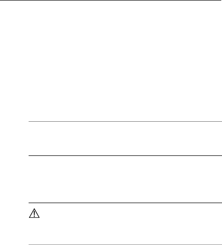
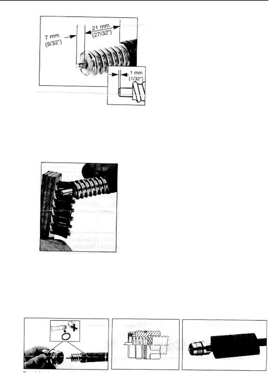
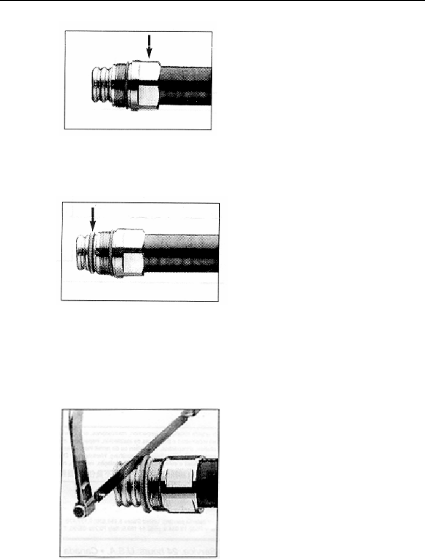
3) Cut the skin of the cable at 28 mm away from the connector with the fast cable
cutter and the safety knife, as shown in Figure C-1.
4) Strip off the outer conductor at 7 mm away from the connector with the fast cable
cutter, and keep the cutting surface smooth, as shown in Figure C-2.
Figure C-1 Cutting cable skin with safety knife
用安全刀切整电缆外皮
Figure C-2 Stripping off outer conductor
5) Remove the foam plastic and the adhesives with the safety knife. Be careful not to
damage the inner conductor, as shown in Figure C-3.
6) Taper the inner conductor with a file and the nipper pliers, as shown in Figure C-4.
Figure C-3 Removing foam plastic and adhesives
Installation Manual
iSiteC BTS3601C CDMA Base Station Hardware Installation
C Making Connectors
C-3
Figure C-4 Tapering inner conductor
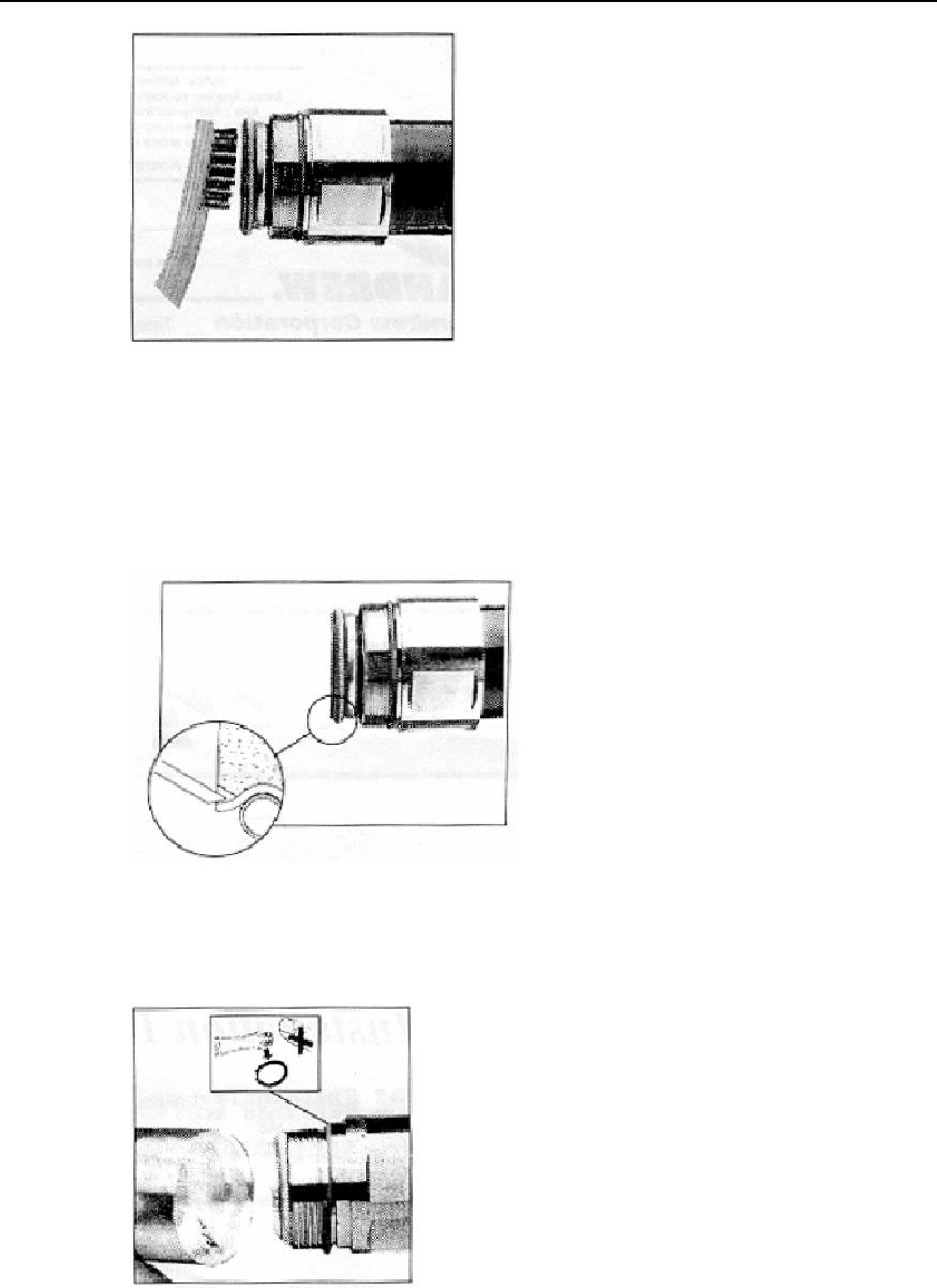
7) Brush off the residuals, as shown in Figure C-5.
Figure C-5 Brushing off residuals
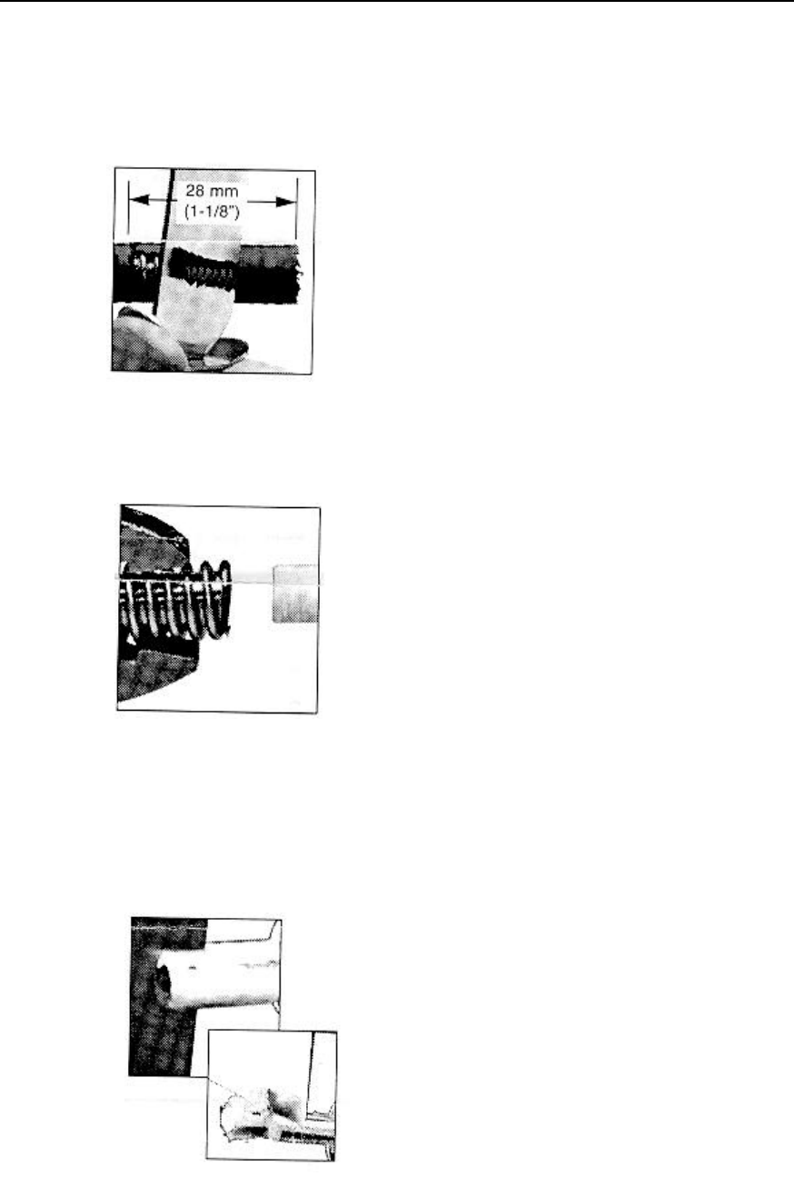
8) Apply grease and mount fixing nut. Place the heat-shrink tube into the cable and
then screw the fixing nut to the cable until it is tight, as shown in Figure C-6.
Figure C-6 Screwing fixing nut onto cable
Installation Manual
iSiteC BTS3601C CDMA Base Station Hardware Installation
C Making Connectors
C-4
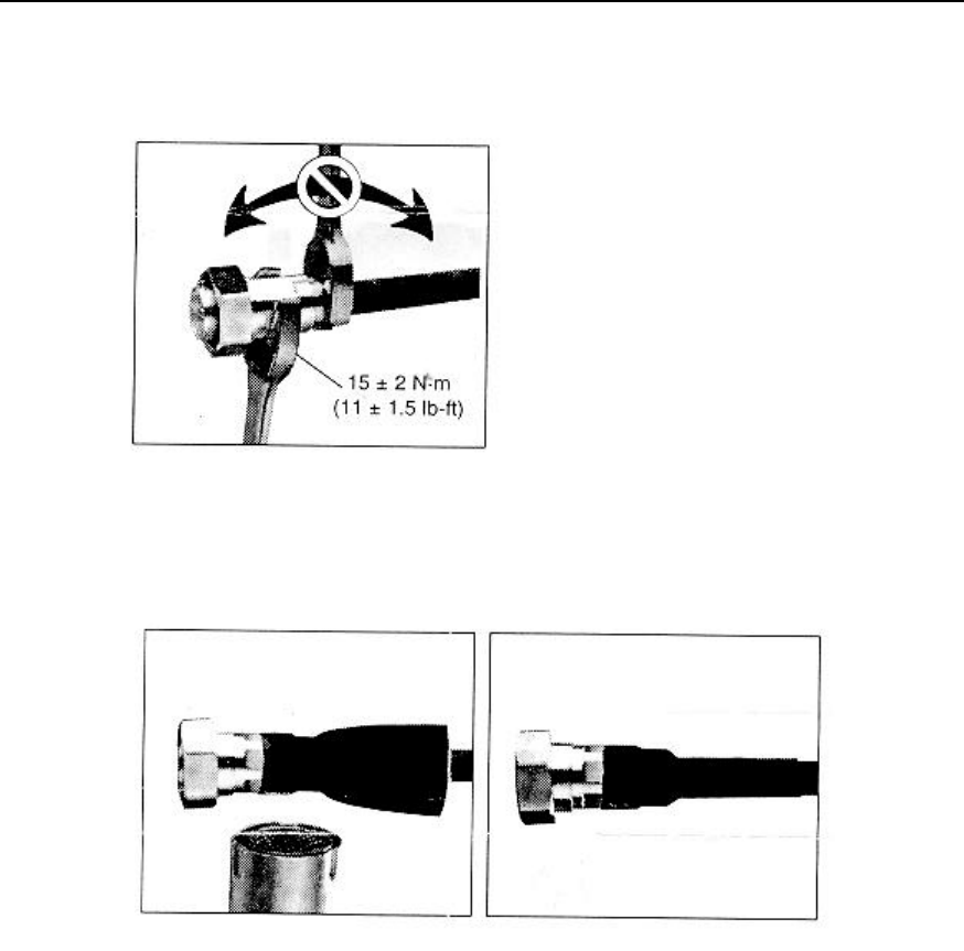
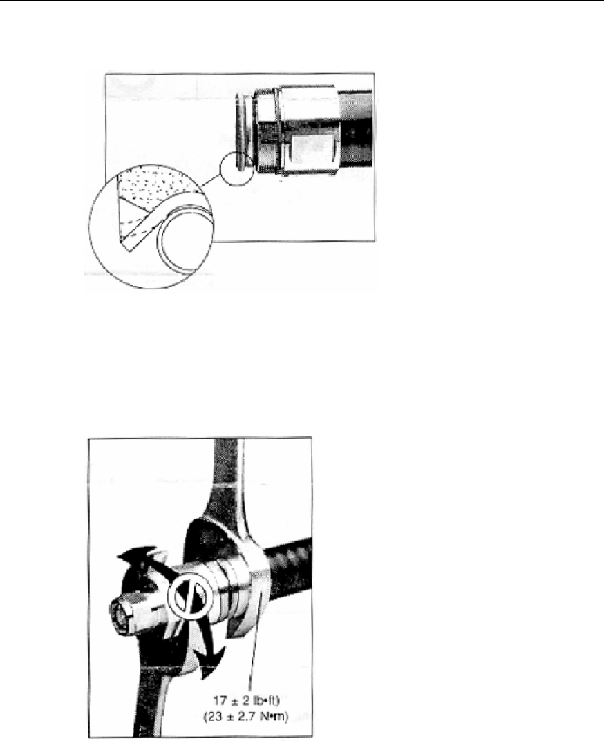
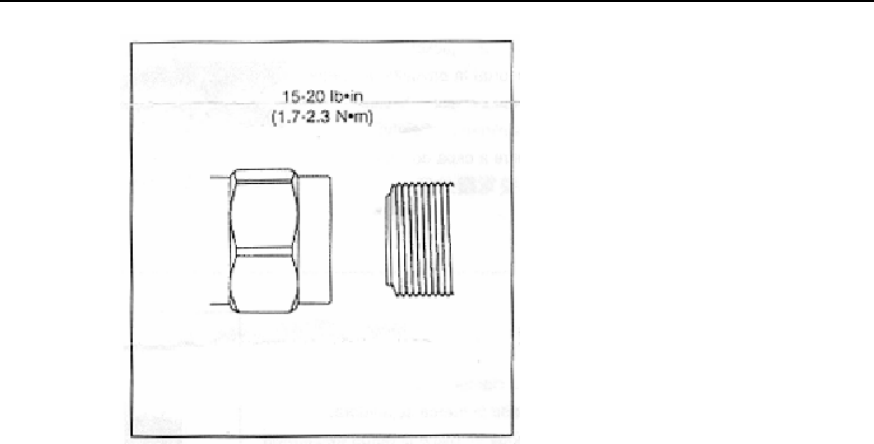
9) Mount the connector cap. Screw the connector cap while keeping the fixing nut still,
as shown in Figure C-7.
Figure C-7 Mounting connector cap
10) Heat up the heat-shrink tube, as shown in Figure C-8.
Figure C-8 Heating up heat-shrink tube
11) Fit torque, as shown in Figure C-9.
Installation Manual
iSiteC BTS3601C CDMA Base Station Hardware Installation
C Making Connectors
C-5
Figure C-9 Fitting torque
12) Be sure to test the connector after it is made. It can only be put into use after it
passes the test.
Caution:
1. Pay attention to safety during the preparation. Improper operation of sharp-edged tools can cause
human injury.
2. Be sure to clean up the feeder remainders to avoid copper scales from mixing up with the connector,
which could adversely affect the performance of the antenna and feeder system.
C.3 Making 7/16 DIN Connector and N Connector for 7/8
Feeder
Caution:
The following takes the preparation of N connector as an example. 7/16 DIN connector is prepared in the
same way.
Installation Manual
iSiteC BTS3601C CDMA Base Station Hardware Installation
C Making Connectors
C-6
I. Tools required
Spanners (one is 19mm and the other is 22mm), fast cable cutter, fast cable stripper,
safety knife, electric blower, diagonal pliers, nipper pliers, pliers, file, brush and ruler
are all required.
II. Making connectors
1) Get the required tools ready and put them in a convenient place.
2) Straighten the end of the feeder to be mounted with a connector.
3) Cut the feeder with a fast cable cutter. The cutting surface should be smooth.
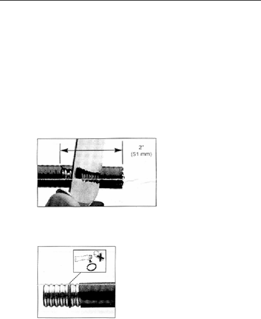
4) Cut the cable skin at 51mm away from the connector with the fast cable cutter and
the safety knife, as shown in Figure C-10.
5) Add O-ring and apply proper amount of grease on it, as shown in Figure C-11.
Figure C-10 Cutting cable skin
Figure C-11 Adding O-ring and applying grease
6) Add fixing nut, as shown in Figure C-12.
7) Place spring ring and fix it in the outer conductor trough of the feeder, as shown in
Figure C-13.
Installation Manual
iSiteC BTS3601C CDMA Base Station Hardware Installation
C Making Connectors
C-7
Figure C-12 Adding fixing nut
Figure C-13 Adding spring ring
8) Adjust the hacksaw and the hacksaw guide (big washer) to cut the cable, as
shown in Figure C-14.
9) Brush off the burr and residuals, as shown in Figure C-15.
Figure C-14 Cutting cable
Installation Manual
iSiteC BTS3601C CDMA Base Station Hardware Installation
C Making Connectors
C-8
Figure C-15 Brushing off residuals
10) Press the foam plastic tightly, as shown in Figure C-16.
11) Add O-ring and apply grease to it. Mount the connector body, as shown in Figure
C-17.
Figure C-16 Pressing foam plastic tightly
Figure C-17 Mounting connector body
Installation Manual
iSiteC BTS3601C CDMA Base Station Hardware Installation
C Making Connectors
C-9
12) Expand the outer conductor with a fast cable stripper (fitting the feeder type).
Check the stretching surface and clean off the residuals, as shown in Figure C-18.
Figure C-18 Stretching outer conductor
13) Refit the connector. Never rotate the connector body while installing, as shown in
Figure C-19.
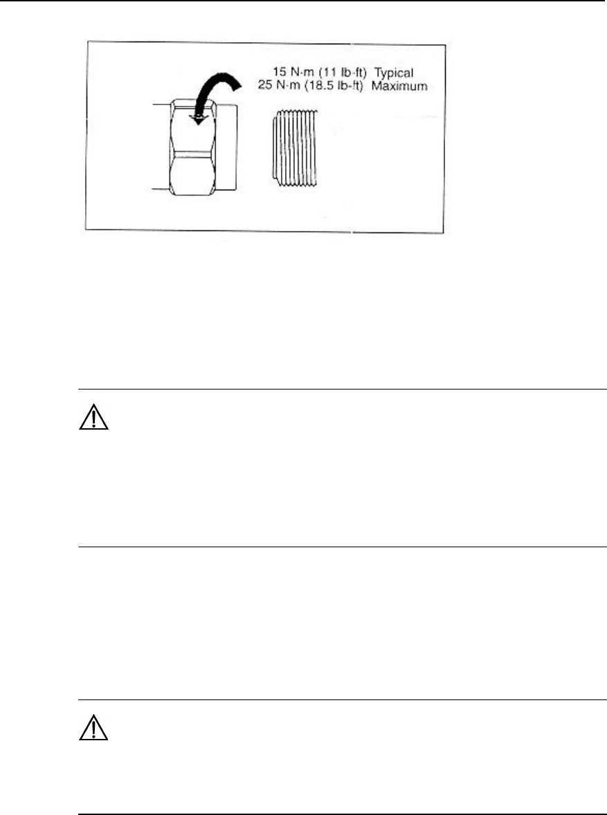
14) Fit the torque, as shown in Figure C-20.
Figure C-19 Fitting connector
Installation Manual
iSiteC BTS3601C CDMA Base Station Hardware Installation
C Making Connectors
C-10
Figure C-20 Fitting torque

Installation Manual
iSiteC BTS3601C CDMA Base Station Hardware Installation
D Preparing Grounding Clips
D-1
D Preparing Grounding Clips
D.1 Overview
During the entire installation, there are many places where grounding clips should be
applied. The following is the summary of the places where grounding clips are required.
1) Normally, each feeder should be grounded at the following three points at least for
lightning-protection:
l Within 1m's reach behind the place where the feeder is led from the tower
platform;
l Within 1m's reach in front of the place where the feeder is led from the tower body
to the outdoor cabling rack;
l At the outer side of the feeder window before which the feeder is led into (on the
spot).
When the length of the feeder along the tower body exceeds 60m, more
lightning-protection grounding clips should be added in the middle of the tower body.
Typically, one clip is installed for every 20m.
2) If the feeder is led into the room after being routed for a stretch of distance on the
building-top, and the distance exceeds 20m, a lightning-protection grounding clip
is required on the top of the building.
3) For the feeder that enters the room from the building-top along the wall, if an
outdoor cabling rack is used, the cabling rack should also be grounded.
D.2 Preparation Process
1) Prepare the required tools, such as paper cutter, flat screwdriver and nipper pliers,
etc.
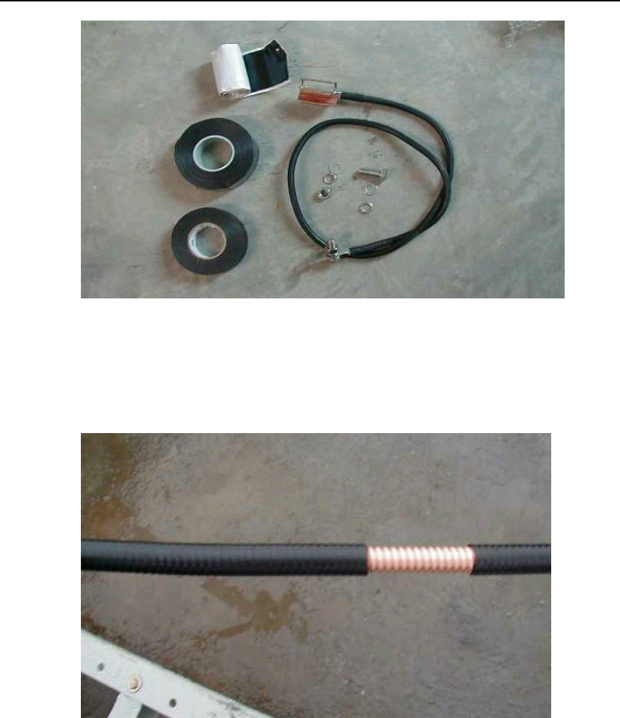
2) Unpack the box and bags containing the lightning-protection grounding clips and
put various parts and accessories on clean ground or paper for use, as shown in
Figure D-1.
Installation Manual
iSiteC BTS3601C CDMA Base Station Hardware Installation
D Preparing Grounding Clips
D-2
Figure D-1 Installation accessories of lightning-protection grounding clips
3) Determine the location for lightning-protection grounding clip installation. Cut the
feeder skin according to the clip size to expose the outer conductor, as shown in
Figure D-2.
Figure D-2 Striping off feeder skin
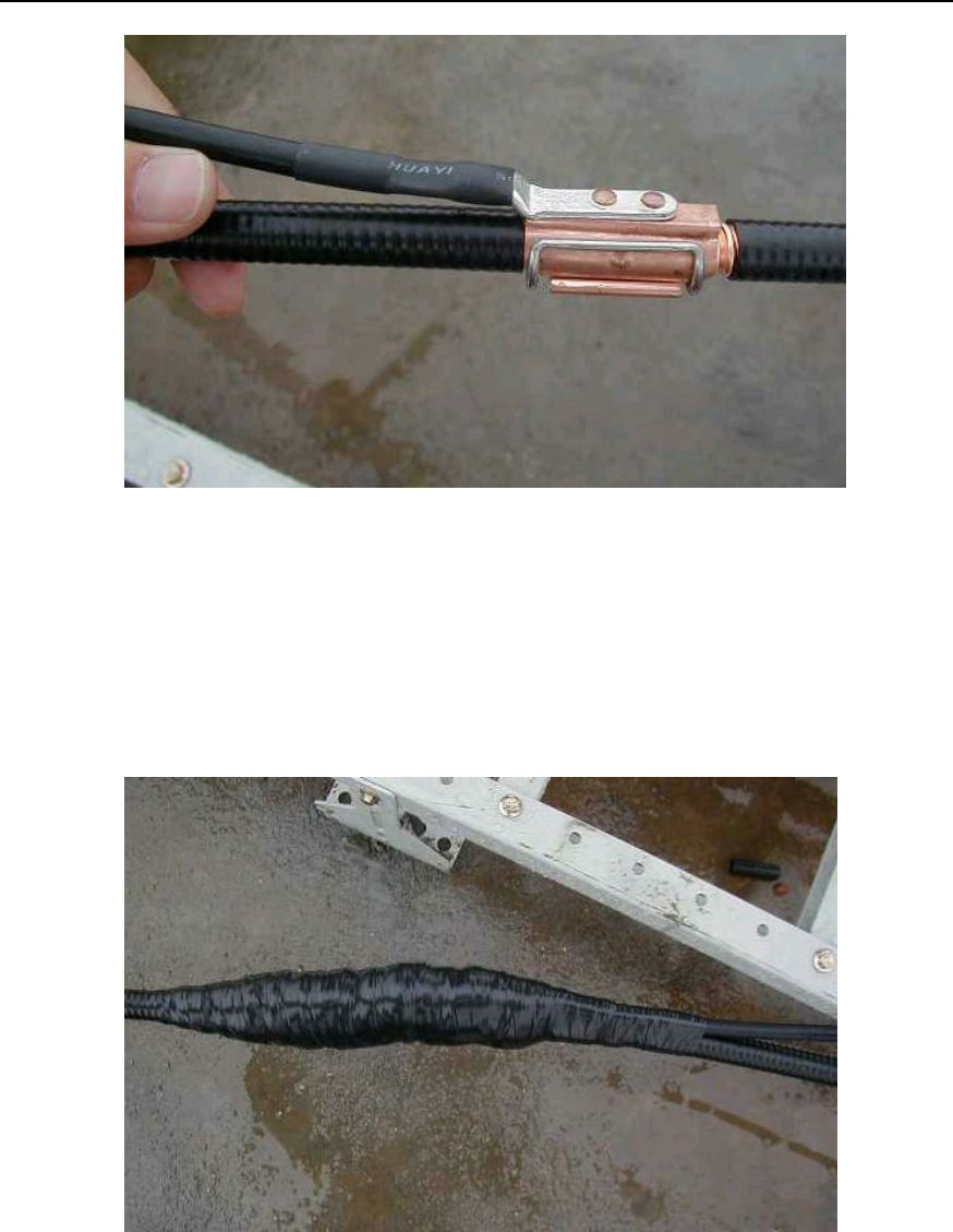
4) Fix the lightning-protection grounding clip on the feeder. The grounding cable of
the clip should be led from the top down with the angle between the feeder and the
grounding cable not greater than 15°, as shown in Figure D-3.
Installation Manual
iSiteC BTS3601C CDMA Base Station Hardware Installation
D Preparing Grounding Clips
D-3
Figure D-3 Lightning protection grounding clip fixed on feeder
5) Wrap up the lightning protection grounding clip with PVC tape, semi-conductive
self-adhesive tape and waterproof tape in turn. When wrapping, do it from the
bottom up, then from the top down and finally from the bottom up again. Each turn
should be overlapped by the next turn for about one-third of the width as shown in
Figure D-4.
Figure D-4 Wrapping lightning protection grounding clip with three layers of tapes
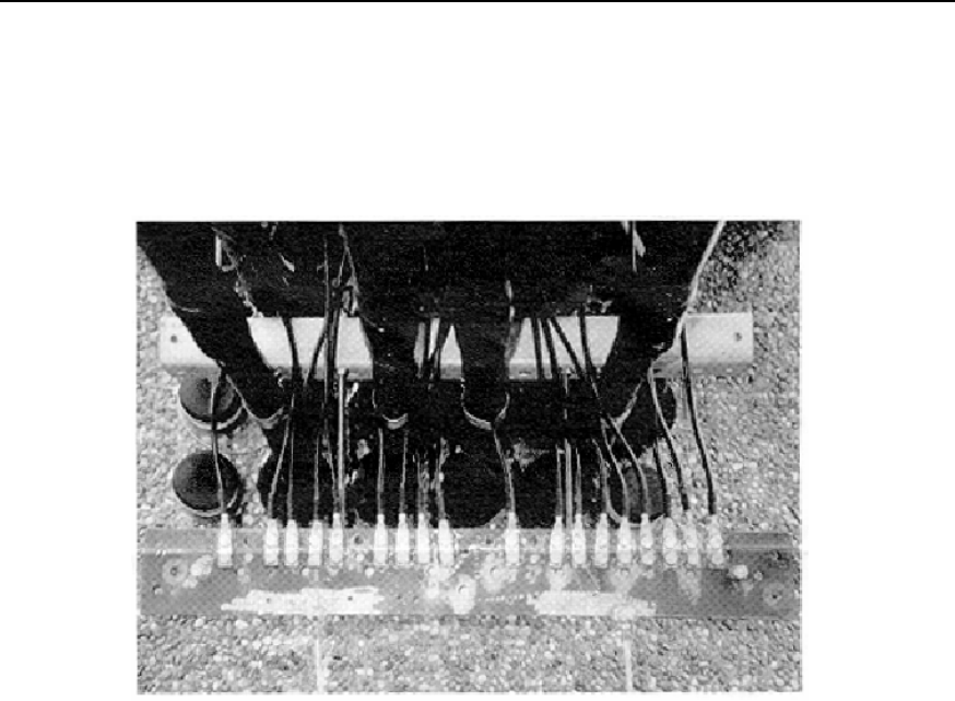
6) The sealed lightning protection grounding clip can be connected to the outdoor
grounding bar, as shown in Figure D-5, as well as to the well-grounded outdoor
cabling rack. The grounding clip in Figure D-4 is connected to the outdoor cabling
rack. When the lightning protection grounding clip is connected to the outdoor
Installation Manual
iSiteC BTS3601C CDMA Base Station Hardware Installation
D Preparing Grounding Clips
D-4
cabling rack, the anti-rust paint at the place where the rack is grounded should be
removed. When the grounding cables are installed, the place should be covered
with anti-rust paint again. Those exposed connector parts should also be painted
with anti-rust paint for good grounding, if they are incapable of being wrapped up
with insulating tapes.
Figure D-5 Lightning protection grounding clip connected to outdoor grounding bar

Installation Manual
iSiteC BTS3601C CDMA Base Station Table of Contents
i
Table of Contents
4 Installing Satellite Synchronization Antenna and Feeder System......................................4-1
4.1 Installing GPS Antenna and Feeder System................................................................4-1
4.2 Installing GPS Antenna ..............................................................................................4-2
4.2.1 Requirements for Installation Position................................................................4-2
4.2.2 Installing GPS Antenna Support........................................................................4-3
4.2.3 Installing Antenna ............................................................................................4-7
4.3 Installing GPS Feeder ................................................................................................4-8
4.3.1 Routing Feeder ................................................................................................4-8
4.3.2 Installing Lightning Arrester ..............................................................................4-9
4.3.3 Grounding Requirement .................................................................................4-11
4.3.4 Feeder Label .................................................................................................4-13

Installation Manual
iSiteC BTS3601C CDMA Base Station Hardware Installation
4 Installing Satellite Synchronization Antenna and Feeder System
4-1
4 Installing Satellite Synchronization Antenna and
Feeder System
This chapter introduces the installation of satellite synchronization antenna and feeder
system taking GPS as an example. In practical installation, it can be performed
simultaneously with that of RF antenna and feeder system.
This chapter will not cover the same contents with the installation of RF antenna and
feeder system. Instead, it focuses on the differences between the installations of the
two systems.
4.1 Installing GPS Antenna and Feeder System
The installation of GPS antenna and feeder system is basically the same with that of
RF antenna and feeder system. The major differences lie between the GPS antenna
and the RF antenna. In addition, GPS antenna and feeder installation includes the
installation of antenna-side and equipment-side lightning arresters. The procedure is:
1) Check the installation environment of GPS antenna and feeder system.
2) Get familiar with the engineering design documents and determine the installation
scheme.
3) Install antenna support.
4) Install antenna.
5) Connect outdoor jumpers.
6) Install antenna-side lightning arrester.
7) Prepare the connectors of feeders, route the outdoor feeders and attach labels on
them.
8) Mount grounding clips for feeders.
9) Install equipment-side lightning arrester;
10) Prepare, route and bind indoor jumpers, and attach labels on them.
11) Inspect the project installation.
&
Note:
The installation of GPS antenna and feeder system can be performed simultaneously with that of RF
antenna and feeder system. The specific installation process can be adjusted according to the actual
configuration and environment.
Installation Manual
iSiteC BTS3601C CDMA Base Station Hardware Installation
4 Installing Satellite Synchronization Antenna and Feeder System
4-2
4.2 Installing GPS Antenna
4.2.1 Requirements for Installation Position
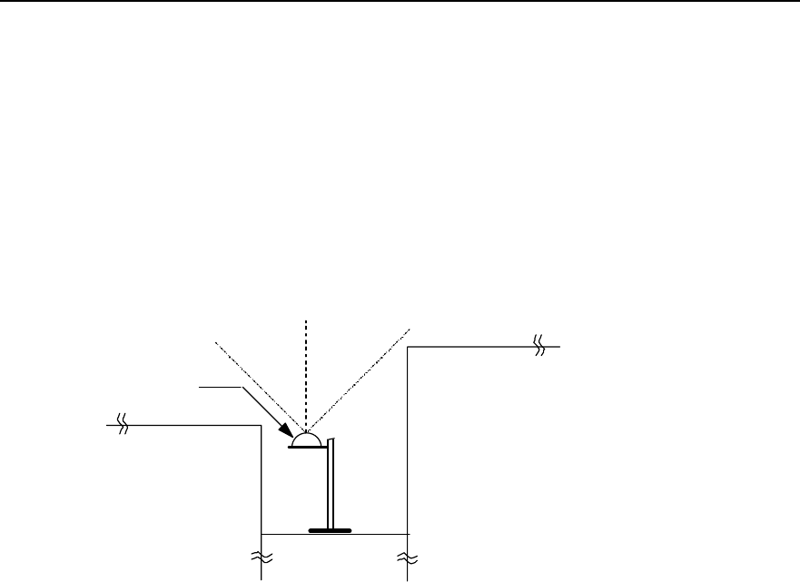
The installation position of GPS antenna should have a broad vision without high
buildings around, and as far as possible from the compact accessory buildings on the
building-top. The available area of the plane for installing GPS antenna should be as
big as possible. And the antenna should be vertically erected with a visual angle
greater than 90°. See Figure 4-1.
(2)
(1) (1)
≥ 90°
(1) Surrounding buildings or other obstacles (2) GPS antenna
Figure 4-1 Antenna installation position
l Note that the antenna should not be close-range radiated by the front of the main
lobe of the mobile communication antenna. In addition, it should not be located at
the range of the microwave signal from microwave antenna, not below the high
voltage cable, nor under the intense radiation of TV launching tower.
l Considering lightning protection, try the best to install the antenna at the center of
the building-top. Do not install it on the stub wall around the building-top. DO not
install it at the corner of the building-top as the corner has the greatest possibility
of being stricken by lightning.
l The antenna should be installed at the place where there is special lightning
arrester or similar facilities such as telecommunication tower around. And the
antenna should be located within the valid protection range of the lightning
arrester. That is, the included angle between the erect direction and the direction
from the antenna RX connector to the lightning arrester or to the tower-top should
be less than 30°. If there is no tower or lightning arrester around, the special
lightning arrester should be installed to meet the design requirements for lightning
protection of the building. The horizontal distance from the lightning arrester to the
antenna should be 2m to 3m preferably. And the lightning arrester should be 0.5m
higher than that of GPS antenna receive connector.
Installation Manual
iSiteC BTS3601C CDMA Base Station Hardware Installation
4 Installing Satellite Synchronization Antenna and Feeder System
4-3
4.2.2 Installing GPS Antenna Support
In terms of varied installations, there are different supports available.
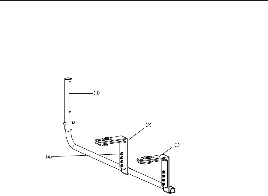
I. On tower
Figure 4-2 illustrates the support installed on tower.
(1) Adjustable clamp (2) Fixed clamp (3) Support (4) M8 bolt
Figure 4-2 Antenna support on tower
Installation procedure is as follows:
1) Unscrew the bolts on the fixed clamps and remove the adjustable clamps;
2) Place the antenna support in the right position on the tower so that the tower angle
steel is between the fixed clamp and the adjustable clamp;
3) Fix the support on the tower with fasteners including bolts, plain washers, spring
washers and nuts;
4) Insert the antenna support lever into the support and put it through the bolt holes.
Tighten the bolts to fix the antenna support.
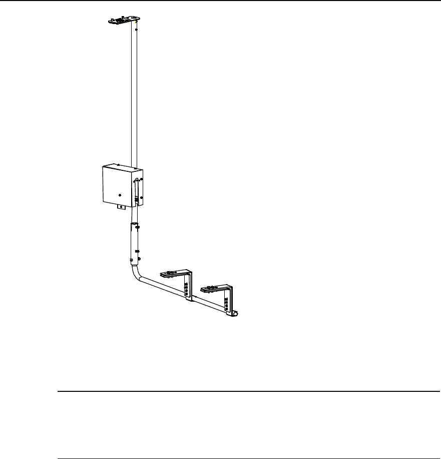
Figure 4-3 illustrates an installed antenna support on tower.
Installation Manual
iSiteC BTS3601C CDMA Base Station Hardware Installation
4 Installing Satellite Synchronization Antenna and Feeder System
4-4
Figure 4-3 Installed antenna support on tower
&
Note:
For the tower without angle steel, the above mentioned antenna support cannot be used. Antenna support
for metal mast can be adopted. Please refer to the section right below for its installation.
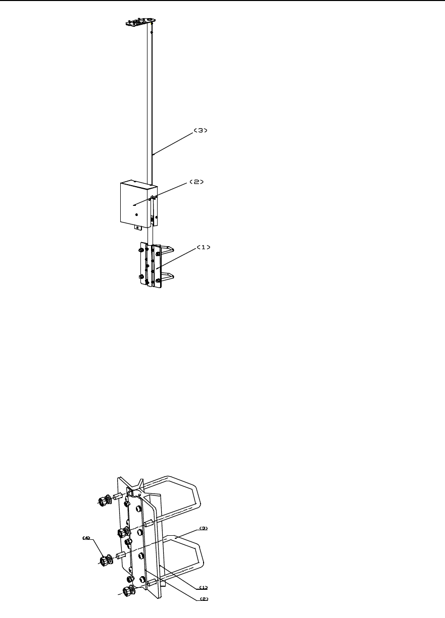
II. On metal mast
The antenna support for installation on metal mast is shown in Figure 4-4.
Installation Manual
iSiteC BTS3601C CDMA Base Station Hardware Installation
4 Installing Satellite Synchronization Antenna and Feeder System
4-5
(1) GPS installation anchor ear (2) Lightning arrester encloser (3) Support
Figure 4-4 Antenna support for installation on metal mast
Installation procedure is as follows:
1) Unscrew the fastening bolts on GPS installation anchor ear and remove the
anchor ear.
2) Round the U-shape clip on the metal mast for GPS antenna. Fasten M10 bolt to fix
the GPS installation anchor ear on the metal mast. The structure of GPS
installation anchor ear is shown in Figure 4-5.
(1) Front clamp (2) Rear clamp (3) U-shape clip (4) M10 bolt
Figure 4-5 Structure of GPS installation anchor bolt
Installation Manual
iSiteC BTS3601C CDMA Base Station Hardware Installation
4 Installing Satellite Synchronization Antenna and Feeder System
4-6
3) Remove the rear clamp on the GPS installation anchor ear. Put the antenna
support lever between the front clamp and the rear clamp. Then adjust the
direction of the antenna support lever.
4) Fasten the rear clamp and the bolts to secure the antenna support lever.
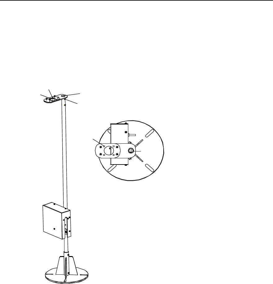
III. On building-top
The GPS antenna support for installation on building-top is shown in Figure 4-6.
M1
M2(4 screws)
M3
B1(2 bolts)
M2
M1
M3
Figure 4-6 Structure of GPS antenna support on building-top
Install procedure is as follows:
1) Place the metal base of the antenna support on the concrete base and align the
centers. Mark the position of the installation holes with an engineering pen.
2) Drill holes at the marks using a drill with the bit of v12.
3) Install expansion bolts to secure the base. In order to keep the antenna pole erect
so as to reach better receiving performance, try to keep the metal base level using
washers.
4) Insert the support lever into the base to see whether the lever is erect. It is required
that the included angle between the support lever and the direction of the plummet
be smaller than 5°. If the requirement can not be satisfied, adjust the base.
Installation Manual
iSiteC BTS3601C CDMA Base Station Hardware Installation
4 Installing Satellite Synchronization Antenna and Feeder System
4-7
4.2.3 Installing Antenna
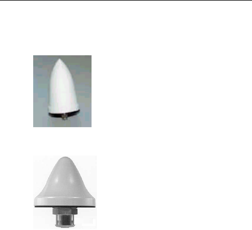
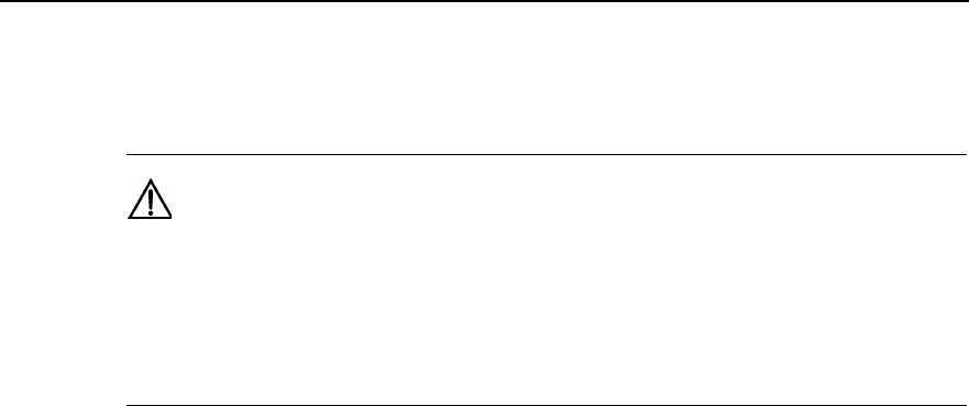
There are various types of antennae. Figure 4-7 and Figure 4-8 show two types of
common antennae. The following gives the installation of two types of GPS antennae
respectively.
Figure 4-7 GPS antenna of type AT1670-0
Figure 4-8 GPS antenna of type UTONCORE
I. Installing GPS antenna of type AT1670-0
1) Insert the jumper connector at the antenna bottom into M3 of the antenna support
as shown in Figure 4-6;
2) Fasten the four accessory UK-standard bolts at M2;
3) Tighten the antenna and the cable connector.
II. Installing GPS antenna of type UTONCORE
1) UTONCORE GPS antenna has such auxiliary fixtures as a rubber washer, a metal
plain washer and a bolt. During installation, first unfix the bolt at the antenna
bottom and install the rubber washer instead. Then insert the antenna into M3 of
the antenna support as shown in Figure 4-6;
2) Install the metal plain washer on the jumper connector at the bottom of the
antenna (with the washer head tightly against the bottom of M3);
Installation Manual
iSiteC BTS3601C CDMA Base Station Hardware Installation
4 Installing Satellite Synchronization Antenna and Feeder System
4-8
3) Tighten the antenna connector and the cable socket. Finally reinstall the unfixed
bolt. Thus the GPS antenna is fixed on the ellipse holder of the antenna support.
Caution:
1) Waterproof treatment should be performed at the antenna connector. Please refer to Section 2.3.6 for
waterproof treatment process.
2) Upon completion of installation, cover the antenna support with anti-rust paint, especially the fastening
bolts, expansion bolts and the places around the bolt holes.
4.3 Installing GPS Feeder
GPS feeder installation includes the installation of jumpers, antenna-side lightning
arrester, feeder, equipment-side lightning arrester, etc. The intallation and routing of
GPS feeder is similar to that of RF feeder. Following gives explanation of points for
attention and grounding requirements during the installation.
4.3.1 Routing Feeder
Prior to feeder routing, carefully check the routing environment including the tower and
building-top. Determine the routing scheme and sequence as per the engineering
drawing.
l In the case of BTS indoor installation, the route leading the feeder from the
installation position to the equipment room containing the cabinet and equipment
should be clear. It should facilitate fixing the cable properly and meet the routing
requirements in the equipment room. In addition, reliable measures should be
taken to protect the feeder from rain and corrosion.
l 1.5m jumper should be bound at the outside of the antenna support lever evenly
with cable ties. In addition all cable ties should be fastened, with the same spacing
of 200mm. The cable tie heads should be toward the same direction, and all the
ties should be cut neatly to the end.
l Waterproof elbow should be made at the entrance where the feeder enters the
equipment room. The vertical distance from the lowest point of the waterproof
elbow to the entrance should not be less than 200mm so as to prevent rain from
entering the room.
l In the case of GPS antenna installed on building-top, connectors at both ends of
the feeder should be protected with strong materials (such as packing bags for
board) to prevent damage to the connectors. The feeder should be fixed with
plastic clips attached with steel nails along the root of the parapet on the
Installation Manual
iSiteC BTS3601C CDMA Base Station Hardware Installation
4 Installing Satellite Synchronization Antenna and Feeder System
4-9
building-top. The spacing between plastic clips should be 1m. And the direction of
the clip heads should be interlaced regularly. If two feeders are joined, they should
be bound together without intersection or curve.
l When routing the feeder, try to expand the feeder roll before routing. Try to avoid
bending of it. If it is unavoidable to bend the feeder, the bent radius should not be
less than the minimum of the allowed bent radius for the cables so as to avoid
damage to the feeder.
Caution:
When the distance from the antenna to the BTS is greater than 100m, 7/8 feeder should be adopted so as
to minimize signal loss. If it is unavailable, 1/2 feeder should be adopted, instead.
4.3.2 Installing Lightning Arrester
There are two types of lightning arresters for GPS antenna, i.e. antenna-side lightning
arrester and equipment-side lightning arrester. The former is used for lightning
protection for active GPS antennae, while the latter for the GPS card. The two arresters
are of the same model.
Currently there are two types of lightning arresters. The installation procedure for each
type is described in detail as follows:
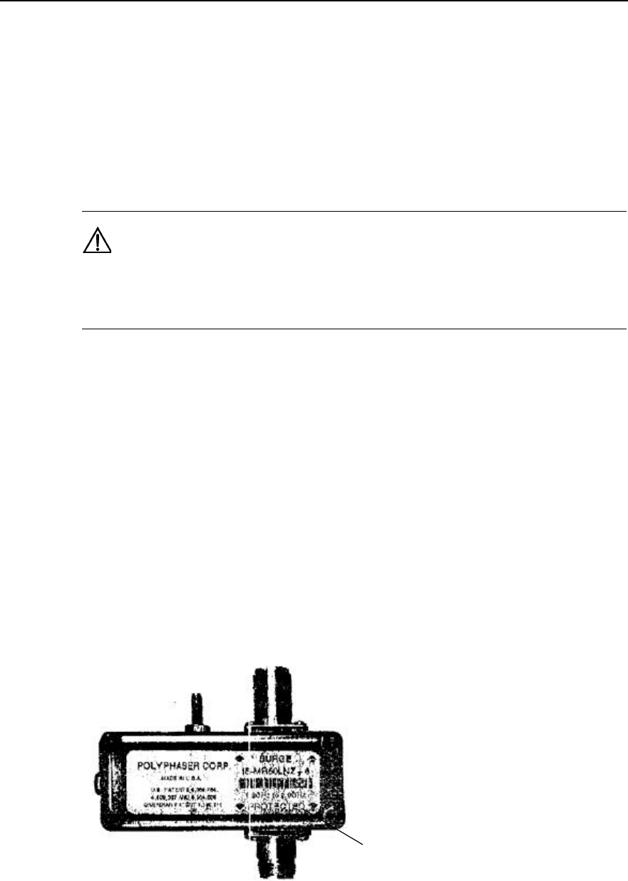
I. Type iS-MR50LNZ+6 lightning arrester
Figure 4-9 illustrates the appearance of Type iS-MR50LNZ+6 lightning arresters.
(1)
(1) PROTECTED end
Figure 4-9 Appearance of Type iS-MR50LNZ+6 lightning arrester
Installation Manual
iSiteC BTS3601C CDMA Base Station Hardware Installation
4 Installing Satellite Synchronization Antenna and Feeder System
4-10
Attention:
1) GPS antenna-side lightning arrester
l The "PROTECTED" end of the GPS lightning arrester should face the antenna.
That is, the "PROTECTED" end of the arrester is connected with the jumper end.
l The lightning arrester should not be grounded when it is installed either on the
tower or on building-top, but the feeder grounding clip should be as close as
possible to the lightning arrester.
l The lightning arrester is installed inside the lightning arrester box, with its
connectors sealed with waterproof adhesive tape and PVC tape in sequence, so
as to prevent moisture invasion.
2) GPS equipment-side lightning arrester
l The "PROTECTED" end of GPS lightning arrester should face the BTS. That is,
the "PROTECTED" end of the arrester is connected with the GPS port of the BTS.
l In the case of BTS indoor installation, dual-male conversion connector should be
used to connect the lightning arrester directly to the GPS port of MBPM. It is
unnecessary to connect the lightning arrester to lightning protection grounding
cable.
l In the case of BTS outdoor installation, dual-male-connector jumper of 0.3m long
should be used to connect the lightning arrester to the GPS port of MBPM. The
arrester should then be connected to the lightning protection grounding cable that
leads to the grounding bar of the BTS. The connector between the arrester and the
feeder should be sealed with waterproof adhesive tape and PVC tape in sequence,
so as to prevent moisture invasion.
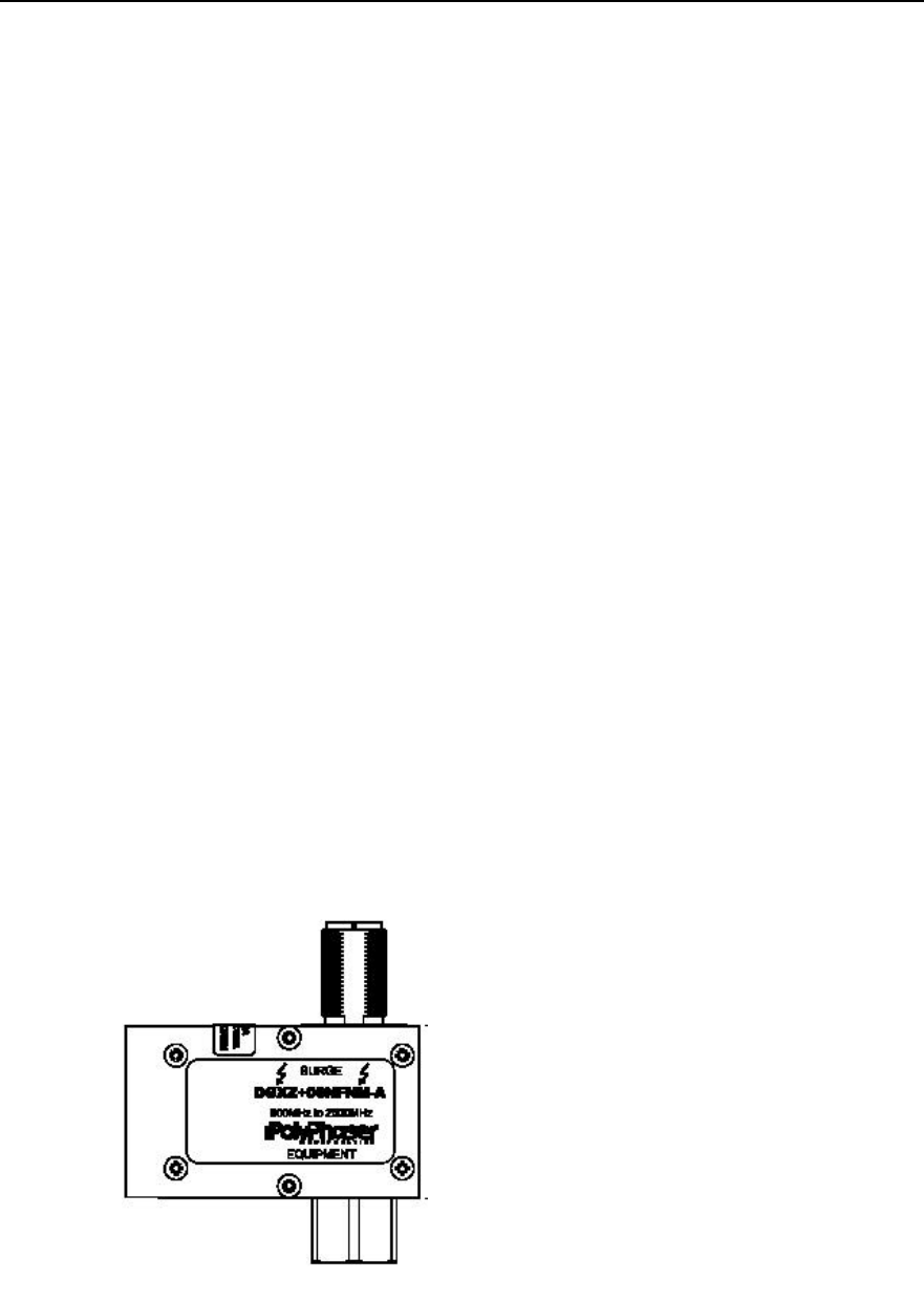
II. Type DGXZ+6NFNM-A lightning arrester
Figure 4-10 illustrates the appearance of Type DGXZ+6NFNM-A lightning arrester.
Figure 4-10 Appearance of Type DGXZ+6NFNM-A lightning arrester
Attention:

Installation Manual
iSiteC BTS3601C CDMA Base Station Hardware Installation
4 Installing Satellite Synchronization Antenna and Feeder System
4-11
1) GPS antenna-side lightning arrester
l The connectors on both ends of Type DGXZ+6NFNM-A lightning arrester are
male and female respectively. Therefore, jumpers with male and female
connectors should be prepared for the installation of the lightning arrester. The
male connector of the jumper is connected with the GPS antenna, while the
female connector on the other end is connected with the male connector of the
lightning arrester.
l The lightning arrester should not be grounded when it is installed either on the
tower or on building-top, but the feeder grounding clip should be as close as
possible to the lightning arrester.
l The lightning arrester is installed inside the lightning arrester box, with its
connectors sealed with waterproof adhesive tape and PVC tape in sequence, so
as to prevent moisture invasion.
2) GPS equipment-side lightning arrester
l In the case of BTS indoor installation, the lightning arrester may be directly
connected to the GPS port of MBPM. And it is unnecessary to connect the
lightning arrester to the lightning protection grounding cable.
l In the case of BTS outdoor installation, a 0.3m jumper with both male and female
connectors should be used. Its male connector is connected to the GPS port of
MBPM of the BTS, while its female connector to the male connector of the
lightning arrester. The lightning arrester should be connected to the lightning
protection grounding cable that leads to the grounding body of the BTS. And the
connector between the lightning arrester and the feeder should be sealed with
waterproof adhesive tape and PVC tape in sequence, so as to prevent moisture
invasion.
4.3.3 Grounding Requirement
GPS feeder grounding and routing are conducted simultaneously. The following gives
description of feeder grounding points in different installations.
I. BTS outdoor installation (building-top installation excluded)
l Within the range of 1m~2m under the GPS antenna;
l The front end connecting the BTS.
Caution:
If the GPS feeder is not longer than 5m, its shielding covering may be grounded only at the front end
connecting the BTS.

Installation Manual
iSiteC BTS3601C CDMA Base Station Hardware Installation
4 Installing Satellite Synchronization Antenna and Feeder System
4-12
II. BTS outdoor installation on building-top
In this installation mode, GPS feeder shielding covering may be grounded only at the
front end connecting the BTS.
III. BTS indoor installation with GPS antenna and BTS antenna installed on the
same tower or metal mast
1) When the outdoor GPS feeder is longer than 20m:
l Within the range of 1m~2m under the GPS antenna;
l Within 1m range of the mast or of where the GPS feeder is led from the tower
platform;
l At the outer side of the feeder window where the GPS feeder enters the equipment
room (connecting to outdoor protection grounding bar).
l Close to the indoor protection grounding bar after it enters the equipment room.
2) When the outdoor GPS feeder is not longer than 20m:
l Within the range of 1m~2m under the GPS antenna;
l At the outer side of the feeder window where the GPS feeder enters the equipment
room (connecting to outdoor protection grounding bar).
l Close to the indoor protection grounding bar after it enters the equipment room.
Caution:
1) If the GPS feeder is longer than 60m, feeder grounding clips should be applied in the middle of the
feeder, with the clip spacing of 20m.
2) If the GPS feeder is led into the room after being routed for a stretch of distance on the building-top, and
the distance exceeds 20m, a feeder grounding clip is required on the top of the building.
3) For the GPS feeder that enters the room from the building-top along the wall, if a cabling rack is used,
the cabling rack should also be grounded.
IV. BTS indoor installation with GPS antenna not on the BTS tower but
separately placed
l The shielding covering of GPS feeder is grounded at the entrance to the building.
The grounding point should be the outdoor grounding bar of the mobile equipment
room. The grounding cable should adopt the plastic insulation copper core wire of
diameter not less than 6mm2. It should be black, or yellow and green.
l If the feeder is longer than 60m, feeder grounding clips should be applied in the
middle of the feeder, with the clip spacing of 20m.
l Place the GPS feeder close to the indoor protection grounding bar after it enters
the equipment room.
Installation Manual
iSiteC BTS3601C CDMA Base Station Hardware Installation
4 Installing Satellite Synchronization Antenna and Feeder System
4-13
Caution:
When the GPS feeder is not longer than 10m, the shielding covering of the coaxial feeder may be
grounded at one point indoor only.
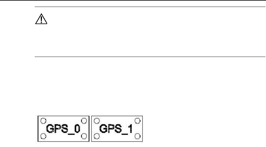
4.3.4 Feeder Label
Figure 4-11 illustrates the standard nameplate used as GPS feeder label.
Figure 4-11 GPS feeder label
I. BTS indoor installation
GPS feeder labels can be affixed in three positions:
l 0.3m to the outdoor feeder connector;
l Outside the feeder entrance to the feeder window;
l 0.3m to the indoor feeder connection.
II. BTS outdoor installation
GPS feeder labels can be affixed in two positions:
l 0.3m to the outdoor feeder connector;
l 0.3m to the front end connecting the BTS.

Installation Manual
iSiteC BTS3601C CDMA Base Station Software Installation & System Commissioning
Table of Contents
i
Table of Contents
1 Overview of Software Installation ......................................................................................1-1
1.1 Overview of Software Installation ................................................................................1-1
1.1.1 BTS Operational Software ................................................................................1-1
1.1.2 Terminal O&M Software ...................................................................................1-2
2 Installing BTS Terminal O&M Software..............................................................................2-1
2.1 Software Features .....................................................................................................2-1
2.2 Installing Local O&M Software....................................................................................2-1
2.2.1 Operational Environment..................................................................................2-1
2.2.2 Conditions .......................................................................................................2-2
2.2.3 Network Configuration ......................................................................................2-2
2.2.4 Software Installation and Instructions ................................................................2-3
2.3 Installing Remote O&M Software ................................................................................2-3
2.3.1 Operational Environment..................................................................................2-3
2.3.2 Conditions .......................................................................................................2-3
2.3.3 Software Installation and Instructions ................................................................2-3
3 Installing BTS Operational Software..................................................................................3-1
3.1 Software Media .........................................................................................................3-1
3.2 Replacing the Chip ....................................................................................................3-1
3.3 Downloading Software ...............................................................................................3-2
3.3.1 Methods of Software Loading............................................................................3-2
3.3.2 Remote Loading ..............................................................................................3-3
3.3.3 Verifying the Software Version ..........................................................................3-7
4 System Commissioning.....................................................................................................4-1
4.1 Modes of System Commissioning ...............................................................................4-1
4.1.1 Local Commissioning .......................................................................................4-1
4.1.2 Remote Commissioning....................................................................................4-1
4.2 Power-on Operation of Software.................................................................................4-1
4.2.1 Board Startup and Indicator Description.............................................................4-2
4.2.2 Setting up OML ................................................................................................4-2
4.2.3 Setting up Abis Signaling Link...........................................................................4-3
4.2.4 Setting up Cells................................................................................................4-3
4.2.5 Normal Operational Status................................................................................4-3
4.2.6 Clock Reference Source...................................................................................4-3
4.3 Commissioning Board Software..................................................................................4-4
4.3.1 Testing Links ...................................................................................................4-4
4.3.2 Processing Faults and Alarms...........................................................................4-4

Installation Manual
iSiteC BTS3601C CDMA Base Station Software Installation & System Commissioning
Table of Contents
ii
4.3.3 Operation and Maintenance..............................................................................4-5
4.4 Call Function Test......................................................................................................4-9
4.4.1 Test Equipment................................................................................................4-9
4.4.2 Preparations for Service Function Test..............................................................4-9
4.4.3 Service Flow Overview...................................................................................4-10
4.4.4 Test of Location Update Flow..........................................................................4-11
4.4.5 Test of MOC Flow..........................................................................................4-12
4.4.6 Test of MTC Flow...........................................................................................4-12
4.4.7 Test of Handoff Flow......................................................................................4-13
4.4.8 Test of Mobile Originated SMS Flow................................................................4-14
4.4.9 Test of Mobile Terminated SMS Flow..............................................................4-14
4.4.10 Test of Mobile Originated Packet Data Flow...................................................4-15
4.4.11 Test of MS Packet Data Flow (Downlink Service Rate) ...................................4-15
4.4.12 Processing of Abnormalities in the Test .........................................................4-16

Installation Manual
iSiteC BTS3601C CDMA Base Station Software Installation & System Commissioning
Table of Contents
i
Table of Contents
1 Overview of Software Installation ......................................................................................1-1
1.1 Overview of Software Installation ................................................................................1-1
1.1.1 BTS Operational Software ................................................................................1-1
1.1.2 Terminal O&M Software ...................................................................................1-2

Installation Manual
iSiteC BTS3601C CDMA Base Station
Software Installation & System Commissioning
0
错误 表格结果无效
1-1
1 Overview of Software Installation
1.1 Overview of Software Installation
BTS3601C software includes BTS operational software and terminal Operation &
Maintenance (O&M) software.
BTS operational software includes BOOT software, Central Processing Unit (CPU)
software, and Field Programmable Gate Array (FPGA) logic.
CPU software includes Micro-bts Base-band Processing Board (MBPB) software and
Micro-bts Transceiver Board (MTRB) software; while FPGA logic includes MBPB logic
and MTRB logic. The actual situation differs from one board type to another.
Terminal O&M software includes Local Maintenance Function (LMF) software (i.e.,
the local O&M software), and O&M Center (OMC) software (i.e., the remote O&M
software).
LMF software comprises PC self-contained Telnet and File Transfer Protocol (FTP)
software, while OMC software is composed of BAM software and Client software.
1.1.1 BTS Operational Software
I. BOOT software
BOOT software serves to start the board. Before the delivery of the BTS3601C, the
BOOTROM in every board has already been installed with BOOT software. BOOT
software upgrade is usually realized by replacing the chip.
II. CPU software
CPU software is the core of system functions. It can be loaded in two ways:
l If there is no old-version software on the board, it is necessary to load the board
(in the commissioning mode) with the software through the board network port.
l If there is old-version software on the board, the software can be upgraded
through software loading by using local FTP software or remote O&M software.
III. FPGA logic
FPGA logic should be loaded to BTS3601C MBPB/MTRB. The loading mode is the
same as that of CPU software.

Installation Manual
iSiteC BTS3601C CDMA Base Station
Software Installation & System Commissioning
0
错误 表格结果无效
1-2
&
Note:
The BTS operational software has been installed before delivery, so there is no need to install onsite.
However, the operational software needs to be upgraded or re-loaded upon version upgrade. For details,
please refer to Chapter 3 BTS Operation Software Installation.
1.1.2 Terminal O&M Software
I. Local O&M software
The local maintenance console is a portable computer installed with Windows9x
Operating System (OS), which contains the local O&M software. It includes FTP
Client (Ftp.exe) and Telnet Client (Telnet.exe).
The BTS3601C objects, including sites, cells, basebands, carriers, channels, etc.,
can be maintained with local maintenance commands.
Since the two programs (Ftp.exe and Telnet.exe) are provided by Windows9x OS,
there is no need for extra installation.
II. Remote O&M software
Remote O&M software (OMC) of the Base Station Subsystem (BSS) adopts the
Client/Server structure.
Through the Client, users can input operation commands, which are then processed
by the server (BAM) in a centralized way. After the processing, these commands are
transmitted to the foreground (including BSC and BTS), which will then return the
operation result (success, failure, timeout, exception, etc.). BAM will record the result
and transmit it in a certain report format to the Client.
With OMC, the user can perform remote maintenance and monitoring over all the
BTSs that are under his control.
The collected site information can also be used for network planning.
The installation of OMC software involves the installation of BAM server software and
the installation of the Client software.
The Client software is divided into three kinds: BSC Client, BTS3612 Client and
BTS3601C Client.
This manual describes the installation of BTS3601C Client software only. For the
installation of BAM server and other Client software, please refer to the
corresponding installation manual.

Installation Manual
iSiteC BTS3601C CDMA Base Station Software Installation & System Commissioning
Table of Contents
i
Table of Contents
3 Installing BTS Operational Software..................................................................................3-1
3.1 Software Media .........................................................................................................3-1
3.2 Replacing the Chip ....................................................................................................3-1
3.3 Downloading Software ...............................................................................................3-2
3.3.1 Methods of Software Loading............................................................................3-2
3.3.2 Remote Loading ..............................................................................................3-3
3.3.3 Verifying the Software Version ..........................................................................3-7

Installation Manual
iSiteC BTS3601C CDMA Base Station
Software Installation & System Commissioning
0
错误 表格结果无效
3-1
3 Installing BTS Operational Software
3.1 Software Media
BTS3601C software has two kinds of media:
l Memory chip
l Disk file
For specific software, their respective media are described as follows:
I. For BOOT software
Boot software includes the fundamental hardware initialization information of boards.
Before delivery, BOOTROMs of all boards are pre-installed with BOOT software,
which can be upgraded by replacing chips.
II. For CPU software
CPU software is the core of system functions. Before delivery, CPU software has
been loaded to the Flash Memory. Once the equipment is powered-on, BOOT
software will load the CPU software from Flash Memory to RAM and run it there.
When CPU software should be reloaded or upgraded during the maintenance
process, CPU software in disk file format can be loaded to the corresponding Flash
Memory through the remote or local maintenance console.
III. For FPGA logic
FPGA logic is responsible for board data exchange. It is loaded in the same way as
the CPU software.
3.2 Replacing the Chip
Generally, the BOOT software is updated by replacing the chip. All you need to do is
to replace the program chip of the old version software with the chip of the new
version.
Installation Manual
iSiteC BTS3601C CDMA Base Station
Software Installation & System Commissioning
0
错误 表格结果无效
3-2
&
Note:
1) The four angles of the chip correspond to those of the socket one by one. Make sure there is no
mistake when replacing the chip. Otherwise, the chip may be burned.
2) The chips should be replaced by authorized Huawei engineers.
3.3 Downloading Software
The boot software of BTS3601C system is installed and upgraded by replacing the
memory chip, while common board software (including CPU software and FPGA logic)
are installed and updated by downloading the software.
3.3.1 Methods of Software Loading
BTS software loading can be conducted through remote/local maintenance console.
The remote maintenance console is connected to BSC via LAN. Through IP Over
ATM (IPOA) link of BSC, it is connected to MBPM of BTS3601C, and through MBPM,
it is connected to Micro-bts Transceiver Module (MTRM).
The local maintenance console is connected to MBPM (via the Ethernet port in
MBPM maintenance window) through the crossover network cable. Through MBPM, it
is then connected to MTRM.
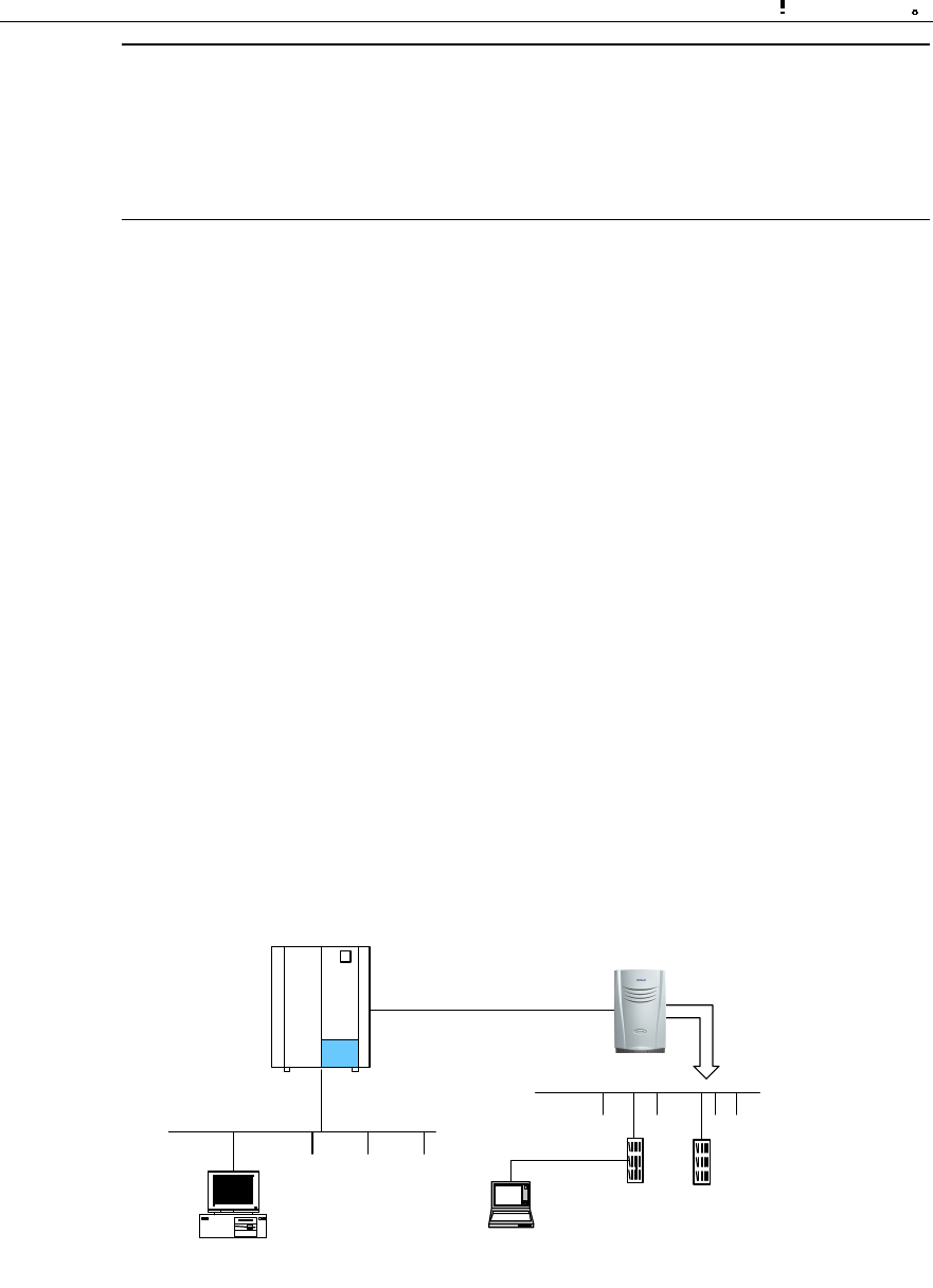
The connection between BTS remote maintenance console and local maintenance
console is shown in Figure 3-1.
BSC BTS3601C
Abis
MBPM MTRM
BAM
(1) (2)
(1) BTS3601C remote maintenance console (2) BTS3601C local maintenance console
Figure 3-1 Connection of BTS3601C maintenance consoles

Installation Manual
iSiteC BTS3601C CDMA Base Station
Software Installation & System Commissioning
0
错误 表格结果无效
3-3
It is quite convenient to load the board software to BTS3601C through remote/local
maintenance console.
The processes of software installation and version upgrade for BTS3601C through
the local and remote maintenance consoles are almost the same.
In the following text, the remote maintenance console is used as an example to
describe the process.
3.3.2 Remote Loading
I. Overview
The system provides the remote loading function to enable the maintenance
personnel to load software to the BTS3601C boards through the remote maintenance
console.
Software loading includes downloading of software and uploading of BTS
configuration data. While the software downloading still comprises two steps:
1) Downloading BTS3601C software;
2) Activating BTS3601C software.
If the loaded software is MBPB software and when it is activated, the BTS3601C will
be reset and MBPB will start the newly-loaded software.
If the loaded software is the MTRB software and when it is activated, MBPB will load
the corresponding MTRB software stored in the memory just now to the specific
board.
In receipt of the new software, the board will activate the software by resetting itself.
The software loading is then completed.
II. Precautions
1) Software loading should be carried out based on the actual conditions.
According to the version matching table, FPGA software should be loaded first,
then the CPU software.
2) Since the solidified software is generally loaded by off-line replacing the chip,
there is no requirement on the sequence.
3) The board software loading should follow the sequence of "MTRB first, MBPB
later". While loading software to a specific board, the sequence of "FPGA first,
CPU later" should be followed.
4) The software version fallback of boards follows the sequence MTRB→MBPB,
the fallback sequence of software on a board is CPU first, then FPGA, so the
general sequence is like this: MTRB.CPUàMTRB.FPGAàMBPB.CPUà
MBPB.FPGA.

Installation Manual
iSiteC BTS3601C CDMA Base Station
Software Installation & System Commissioning
0
错误 表格结果无效
3-4
III. Trouble shooting
Case One: Failed to activate after successful downloading.
Cause analysis: Incorrect parameter for software downloading command, e.g.,
wrong software version No., may result in unsuccessful activation after successful
downloading.
Case two: Failed to download.
Cause analysis: Check the loading sequence first. If that is fine, check the following:
l Is the BAM FTP server powered on?
l Is the access directory open?
l Are the login user name and password correct?
l Does the access directory/file exist?
IV. Specific process of software downloading
1) Preparing for software downloading
Copy the board software to be downloaded to the BTS3601C software loading
directory, which is designated in the BAM. Make sure that the file is writable and
readable.
Meanwhile, note down the software version information.
Finally, log in to the BAM through the remote maintenance console after starting the
FTP server at BAM side.
2) Adding the software loading information in the remote BTS3610C maintenance
system
Run the remote maintenance console software (AirBridge cBSS Client), and select
BTS Management in the command tree.
Select Mini-BTS Management\Mini-BTS Loading Management\Add Mini-BTS Loading
Information (MICRO>ADD BTSLDINFO). Click , the shortcut icon of command
Create Input Interface, and input the following:
l [Board Type]: Select the type of the board whose loading information is to be
added.
l [Software Type]: Select the type of board software;
l [Software Version]: Input the version No. (which must meet the related
specification) of the software to be downloaded;
l [File Path]: Input the path for the software to be loaded (i.e. the software loading
directory in the previous step);
l [File Name]: Input the name (the corresponding file name under the software
loading directory in the previous step) of the file to be loaded.

Installation Manual
iSiteC BTS3601C CDMA Base Station
Software Installation & System Commissioning
0
错误 表格结果无效
3-5
Click , the shortcut icon of Execute Command, to add the software loading
information of the corresponding board.
3) Downloading software
Run the remote maintenance console software (AirBridge cBSS Client), and select
BTS Management in the command tree.
Select Mini-BTS Management\Mini-BTS Loading Management\Download BTS
Software or Data Operation (MICRO>DLD BTSSW).
Click , the shortcut icon of command Create Input Interface, and input the
following:
l [BTS Name]: Input the name of the BTS to be downloaded with software (this
entry may be omitted);
l [BTS ID]: Input the ID of the BTS to be downloaded with the software;
l [Software Activation Mode]: Select the activation mode for the software to be
downloaded;
l [Object Type]: Select the type of the object to which the software is to be
downloaded;
l [Software Type]: Select the type of the software to be downloaded;
l [Software Version]: The information that is input here must be consistent with the
version No. of the software whose loading information has been added in the
system;
l [Board ID]: Select the ID of the MTRB to be downloaded with the software.
Click , the shortcut icon Execute Command, to download the software for the
corresponding board.
If the software activation mode is set to be "Automatic Activation", the software will be
activated automatically after the downloading.
V. Activation of BTS3601C software
Run the remote maintenance console software (AirBridge cBSS Client), and select
BTS Management in the command tree.
Select Mini-BTS Management\Mini-BTS Loading Management\Activate Mini-BTS
Software/Configuration (MICRO>ACT BTSSW).
Click , the shortcut icon of command Create Input Interface, and input the
following:

Installation Manual
iSiteC BTS3601C CDMA Base Station
Software Installation & System Commissioning
0
错误 表格结果无效
3-6
[BTS Name]: Input the name of BTS whose software is to be activated (this entry may
be omitted);
[BTS ID]: Input the ID of the BTS whose software is to be activated;
[Object Type]: Select the type of the object whose software is to be activated;
[Software Type]: Select the type of the software to be activated;
[Software Version]: Input the version No. of the software to be activated;
[Board ID]: Select the ID of the corresponding board.
Click , the shortcut icon of Execute Command, to activate the corresponding
board software/data.
&
Note:
The activation of the software can be conducted automatically by the system if the [Software Activation
Mode] is set as "Automatic" during the setup to download the software.
VI. Uploading of BTS3601C configuration data
Run the remote maintenance console software (AirBridge cBSS Client), and select
BTS Management in the command tree.
Select Mini-BTS Management\Mini-BTS Loading Management\Upload BTS Data
Operation (MICRO>ULD BTSCFG).
Click , the shortcut icon of command Create Input Interface, and input the
following:
[BTS Name]: Input the name of BTS whose configuration data is to be uploaded (this
entry may be omitted);
[BTS ID]: Input the ID of the BTS whose data is to be uploaded;
[Object Type]: Select the type of the object whose data is to be uploaded.
Click , the shortcut icon of command Execute Command, to upload the
corresponding BTS3601C configuration data.

Installation Manual
iSiteC BTS3601C CDMA Base Station
Software Installation & System Commissioning
0
错误 表格结果无效
3-7
If this operation is successful, BTS3601C will operate by FTP to upload the
configuration information of the specified version to the remote BAM, and save it
under the file loading path designated when adding the software loading information.
3.3.3 Verifying the Software Version
You can execute a query command through the remote/local maintenance console to
get the version information of the running software on BTS3601C boards.
I. Get the version information of board software through the remote
maintenance console
Run the remote maintenance console software (AirBridge cBSS Client), and select
BTS Management in the command tree.
Select Mini-BTS Management\Mini-BTS Equipment Management\Query Mini-BTS
Board Version Information (MICRO>DSP BTSBRDVER).
Click , the shortcut icon of command Create Input Interface, and input the
following:
[BTS Name]: Input the name of the BTS which is to be downloaded with software
(this entry may be omitted);
[BTS ID]: Select the ID of the BTS to be queried;
[Board Type]: Select the type of the BTS board to be queried;
[Board ID]: Select the ID of the BTS MTRB to be queried (if [Board Type] is selected
to be Micro-bts Base-band Processing Board (MBPB), this parameter will not appear).
Click , the shortcut icon of Execute Command, to get the query result of BTS
board version information in the maintenance window.
II. Query the board version information through the local maintenance
console
Start Telnet at the local maintenance console. Input the following command under the
prompt character after the login:
DSP BTSBRDVER:BRDTP=<MBPB>,BRDID=<0>
BRDTP is the type of the board to be queried, and BRDID is the ID of the board to be
queried.

Installation Manual
iSiteC BTS3601C CDMA Base Station
Software Installation & System Commissioning
0
错误 表格结果无效
3-8
&
Note:
1) When BRDTP is selected as MTRB, the parameter BRDID (value range: 0-5) must be specified.
2) When BTDTP is selected as MBPB, the parameter BRDID (value: 0) is optional.

Installation Manual
iSiteC BTS3601C CDMA Base Station Software Installation & System Commissioning
Table of Contents
i
Table of Contents
2 Installing BTS Terminal O&M Software..............................................................................2-1
2.1 Software Features .....................................................................................................2-1
2.2 Installing Local O&M Software....................................................................................2-1
2.2.1 Operational Environment..................................................................................2-1
2.2.2 Conditions .......................................................................................................2-2
2.2.3 Network Configuration ......................................................................................2-2
2.2.4 Software Installation and Instructions ................................................................2-3
2.3 Installing Remote O&M Software ................................................................................2-3
2.3.1 Operational Environment..................................................................................2-3
2.3.2 Conditions .......................................................................................................2-3
2.3.3 Software Installation and Instructions ................................................................2-3

Installation Manual
iSiteC BTS3601C CDMA Base Station
Software Installation & System Commissioning
0
错误 表格结果无效
2-1
2 Installing BTS Terminal O&M Software
2.1 Software Features
BTS3601C terminal O&M software (hereinafter referred to as "terminal O&M
software") is classified into two categories: the remote O&M and the local O&M.
These two categories differ in the way they are installed.
I. Local O&M software
Local O&M software includes FTP Client (Ftp.exe) and Telnet Client (Telnet.exe). The
two programs are both self-contained by Windows9x OS.
To realize the local maintenance, the maintenance console is connected through
crossover network cables to BTS via the Ethernet port that is in the Micro-bts
Base-band Processing Module (MBPM) maintenance window. The user thus can
issue O&M commands through the local maintenance console to maintain the
BTS3601C.
II. Remote O&M software
The remote O&M software comprises the software for the BAM server and the Client.
Among which, the Client software is composed of three parts: BSC Client, BTS3612
Client and BTS3601C Client. The remote O&M software described in this manual
refers to BTS3601C Client.
2.2 Installing Local O&M Software
2.2.1 Operational Environment
I. Hardware environment
Basic hardware configuration of the WS (desk-top computer):
l Pentium 100 CPU
l One 500Mbyte hard disk
l One 8Mbyte memory
l One integrated network card
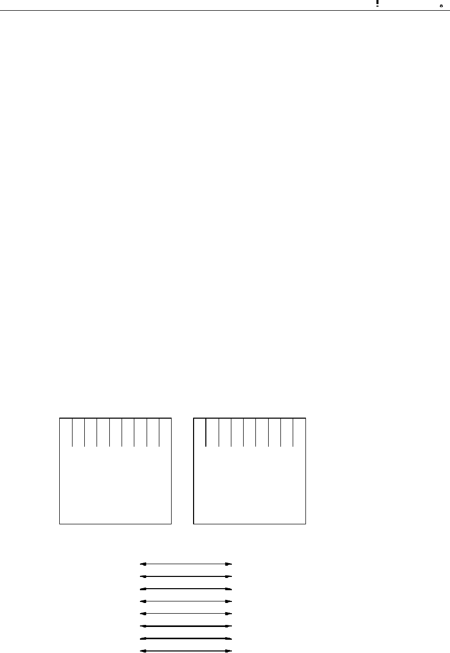
Installation Manual
iSiteC BTS3601C CDMA Base Station
Software Installation & System Commissioning
0
错误 表格结果无效
2-2
II. Software configuration
Windows 95 or Windows 98.
2.2.2 Conditions
For the normal operation of the local maintenance console, the following conditions
should be met:
1) The hardware environment are ready;
2) Windows9x OS can operate normally;
3) Windows9x installation files and network card driver (provided by the original
manufacturer) are furnished.
2.2.3 Network Configuration
This involves the installation and configuration of the network card and the TCP/IP.
The configuration is performed through the functional items of "Add new hardware"
and "Network" in turn on the "Control Panel" of the computer.
The IP address of the maintenance console should be in the same network segment
as that of BTS3601C MBPM network port. In addition, the address should be unique
in the IP addresses of the network equipment.
The connection sequence of network cables (crossover cable) at the network port is
shown in Figure 2-1.
RJ45
Green and white
Green
Yellow and white
Blue
Blue and white
Yellow
Blown and white
Blown
Yellow and white
Yellow
Green and white
Blue
Blue and white
Green
Blown and white
Blown
RJ45
1
2
3
4
5
6
7
8
3
6
1
4
5
2
7
8
RJ45
Green and white
Green
Yellow and white
Blue
Blue and white
Yellow
Blown and white
Blown
Yellow and white
Yellow
Green and white
Blue
Blue and white
Green
Blown and white
Blown
RJ45
1
2
3
4
5
6
7
8
3
6
1
4
5
2
7
8
Figure 2-1 Connection sequence of crossover network cables

Installation Manual
iSiteC BTS3601C CDMA Base Station
Software Installation & System Commissioning
0
错误 表格结果无效
2-3
2.2.4 Software Installation and Instructions
Since Local O&M software (Ftp.exe and Telnet.exe) is self-contained by Windows9x,
there is no need for extra installation.
To run Ftp/Telnet, click [Start/Run] in the system menu of the computer, and input "ftp
xxx.xxx.xxx.xxx"/"telnet xxx.xxx.xxx.xxx" into the dialogue box of [Run].
"xxx.xxx.xxx.xxx" is the IP address of MBPM network port. Ftp/Telnet is then started
for you to log in to the MBPM.
2.3 Installing Remote O&M Software
2.3.1 Operational Environment
The remote O&M software (referring to the BTS3601C Client software here) should
be installed to the same computer together with BSC Client and BTS3612 Client.
2.3.2 Conditions
1) Make sure the computer is installed with only the software necessary for the
system. Otherwise, there may be operational conflicts that may affect the normal
operation of the Client software. Moreover, make sure that a nice and stable
network hardware environment has been established.
2) Obtain from Huawei the complete set of installation files and read-me files, as
well as a legal product serial number.
3) BTS3601C Client software should be installed only after the corresponding BSC
Client and BTS3612 Client have been installed. Before installation, please make
sure that the versions of the three kinds of software are consistent.
2.3.3 Software Installation and Instructions
The BSC Client and BTS3612 Client (both are of the matching versions) should have
been installed first (for instructions, please refer to the corresponding parts in
BSC/BTS3612 installation manuals). After that, to install BTS3601C Client software,
the procedures include:
I. Starting SETUP.EXE
After inserting the installation disk into the disk drive, different alternatives are
provided for:
l If auto execution has been set for the system, the program will be started then.
l Or, you should click [Start/Run] in the system menu and key in "SETUP" and the
corresponding driver icon and path, and press <Enter>.
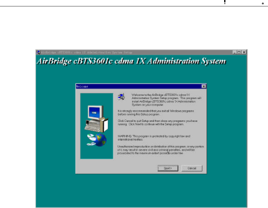
Installation Manual
iSiteC BTS3601C CDMA Base Station
Software Installation & System Commissioning
0
错误 表格结果无效
2-4
l You can also click [SETUP.EXE] in the Resource Manager to run the program.
l You can copy the files in the installation disk to the hard disk and run them.
The initial installation interface as shown in Figure 2-2 will then pop up.
Figure 2-2 Initial installation interface
Click <Next> to continue (or click <Cancel> to exit the installation).
II. License agreement and installation instructions
The [Software License Agreement] will pop up as shown in Figure 2-3. After reading it
carefully, click <Yes> to accept it and continue (or <No> to exit the installation).
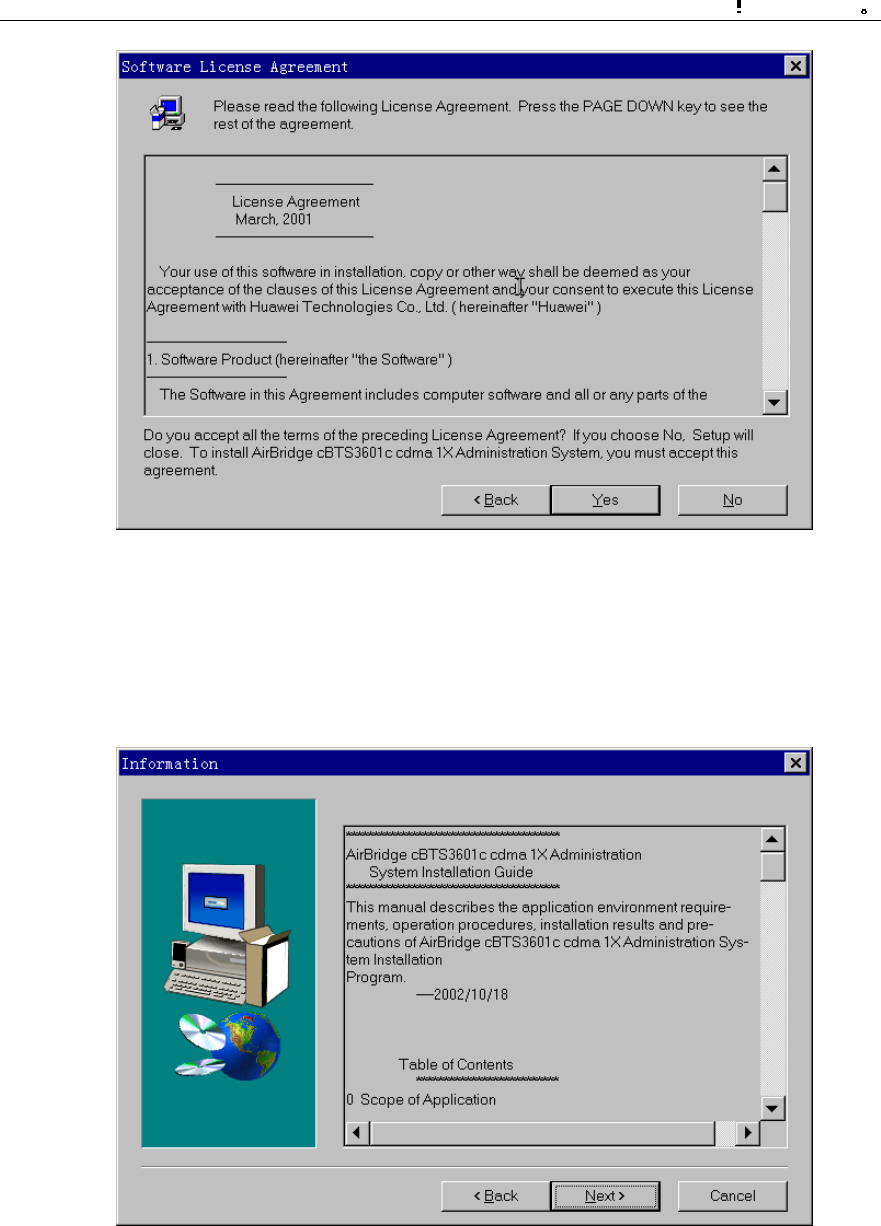
Installation Manual
iSiteC BTS3601C CDMA Base Station
Software Installation & System Commissioning
0
错误 表格结果无效
2-5
Figure 2-3 Software license agreement interface
The installation wizard will guide you how to install the software step by step, as
shown in Figure 2-4. It may contain some latest installation information not given in
this manual. Read the information carefully, then click <Next> to continue.
Figure 2-4 Interface of system installation instructions
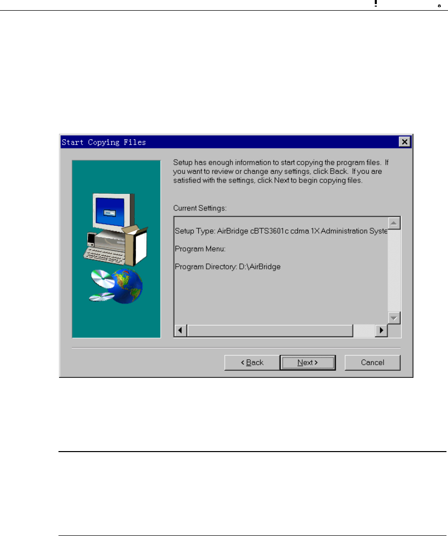
Installation Manual
iSiteC BTS3601C CDMA Base Station
Software Installation & System Commissioning
0
错误 表格结果无效
2-6
III. Confirming the installation information
You are required to confirm the installation information as shown in Figure 2-5 before
copying files.
If you want to change the installation information, please click <Back> to return to the
previous step. Otherwise, click <Next> to continue.
Figure 2-5 Confirming the installation information
&
Note:
The default installation path for BTS3601C Client software is D:\AirBridge, the same as that of BSC
Client and BTS3612 Client. If the installation path of BSC/BTS3612 Client has been changed, the
installation program of BTS3601C Client will automatically find the new one.
IV. Completing the installation
After confirming the installation information, the installation program will start copying
files. In the process of file copying, the installation program will show such information
including overall progress, available disk space, available memory and progress of
individual file copying.
Upon the completion of the installation, the window [Setup Complete] as shown in
Figure 2-6 will pop up.
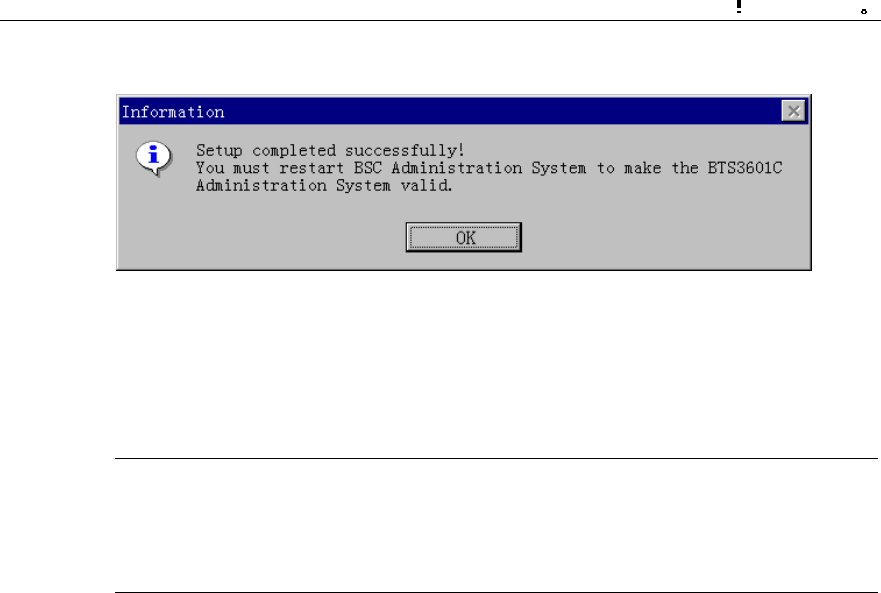
Installation Manual
iSiteC BTS3601C CDMA Base Station
Software Installation & System Commissioning
0
错误 表格结果无效
2-7
Click <OK>, and the system should be restarted to make the Client software valid.
Figure 2-6 End of the installation
That is the end of the installation of BTS3601C Client software.
&
Note:
The above described installation procedure is the one in normal situation. If abnormality occurs at any
installation procedure, please follow the system prompts.
After the installation, click [Start/Program/Airbridge cBSS cdma 1X Administration
System/ AirBridge cBSS Client] to start the Client software.
The operation interface is shown in Figure 2-7.
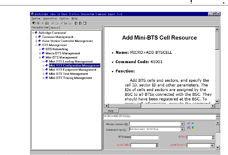
Installation Manual
iSiteC BTS3601C CDMA Base Station
Software Installation & System Commissioning
0
错误 表格结果无效
2-8
Figure 2-7 Operation interface of remote O&M software

Installation Manual
iSiteC BTS3601C CDMA Base Station Software Installation & System Commissioning
Table of Contents
i
Table of Contents
4 System Commissioning.....................................................................................................4-1
4.1 Modes of System Commissioning ...............................................................................4-1
4.1.1 Local Commissioning .......................................................................................4-1
4.1.2 Remote Commissioning....................................................................................4-1
4.2 Power-on Operation of Software.................................................................................4-1
4.2.1 Board Startup and Indicator Description.............................................................4-2
4.2.2 Setting up OML ................................................................................................4-2
4.2.3 Setting up Abis Signaling Link...........................................................................4-3
4.2.4 Setting up Cells................................................................................................4-3
4.2.5 Normal Operational Status................................................................................4-3
4.2.6 Clock Reference Source...................................................................................4-3
4.3 Commissioning Board Software..................................................................................4-4
4.3.1 Testing Links ...................................................................................................4-4
4.3.2 Processing Faults and Alarms...........................................................................4-4
4.3.3 Operation and Maintenance..............................................................................4-5
4.4 Call Function Test......................................................................................................4-9
4.4.1 Test Equipment................................................................................................4-9
4.4.2 Preparations for Service Function Test..............................................................4-9
4.4.3 Service Flow Overview...................................................................................4-10
4.4.4 Test of Location Update Flow..........................................................................4-11
4.4.5 Test of MOC Flow..........................................................................................4-12
4.4.6 Test of MTC Flow...........................................................................................4-12
4.4.7 Test of Handoff Flow......................................................................................4-13
4.4.8 Test of Mobile Originated SMS Flow................................................................4-14
4.4.9 Test of Mobile Terminated SMS Flow..............................................................4-14
4.4.10 Test of Mobile Originated Packet Data Flow...................................................4-15
4.4.11 Test of MS Packet Data Flow (Downlink Service Rate) ...................................4-15
4.4.12 Processing of Abnormalities in the Test .........................................................4-16

Installation Manual
iSiteC BTS3601C CDMA Base Station
Software Installation & System Commissioning
0
错误 表格结果无效
4-1
4 System Commissioning
4.1 Modes of System Commissioning
4.1.1 Local Commissioning
Local commissioning is performed through BTS3601C local maintenance console.
The user can log in to the BTS3601C in the Telnet mode, and commission the
BTS3601C objects with Man-Machine-Language (MML) commands.
Please refer to the module of "Maintenance Console" in User Manual for details of
commissioning commands.
4.1.2 Remote Commissioning
In the remote commissioning mode, the user can input the commissioning command
at the OMC Client. After receiving the command, BAM server will process it and send
it to the BTS3601C. When the response returns from the BTS3601C, BAM server will
record the operation result (success, failure, timeout, abnormality, etc.) and send the
returned operation result in a certain report format to the Client.
For specific operations, please refer to cBSC Operation Manual.
4.2 Power-on Operation of Software
After the BTS3601C is powered on, the software of various boards will conduct
self-test and necessary initialization.
After the system operation becomes stable, MBPB will acquire the basic configuration
parameters to set up the Operation & Maintenance Link (OML) for the BTS3601C
(The protocol involved is BOOTP, a standard protocol in TCP/IP protocol family, which
can be used to obtain IP automatically).
MBPB will also judge whether there are correct configuration data in the BTS3601C
Flash Memory. If there are correct configuration data, MBPB will directly send the
data to each board for configuration. If there is no correct data, MBPB will request the
data from OMC, and send it to the BTS3601C boards for configuration.
The following section briefs the startup and operation of BTS3601C.

Installation Manual
iSiteC BTS3601C CDMA Base Station
Software Installation & System Commissioning
0
错误 表格结果无效
4-2
4.2.1 Board Startup and Indicator Description
When the BTS3601C is powered-on, BOOT software of each board will start running
to transfer CPU software from Flash Memory to Random-Access Memory (RAM), and
start the self-test and initialization.
If the initialization is successful, the board will send a request to Operation &
Maintenance Unit (OMU) for configuration; otherwise, board will be reset and
restarted.
There are three indicators on both the board panels in the maintenance window of
MBPM and MTRM respectively. From top to bottom they are: RUN (operation
indicator, green), ALM (alarm indicator, red) and ACT (work indicator, green).
The following briefs the statuses of indicators. For details, please refer to chapter
"Introduction to Module Maintenance Window" in the User Manual.
l When MBPB/MTRB has no configuration data, all the three indicators will fast
flash at the frequency of 4Hz.
l When MBPB/MTRB is downloading the software, indicator RUN will fast flash at
the frequency of 4Hz.
l When the board is in normal operation, indicator RUN flashes slowly at the
frequency of 0.5Hz, while "ACT" keeps on, and "ALM" is off.
l When alarms occur in the operation of the board, indicator ALM will flash at
different frequencies to indicate different alarm levels.
4.2.2 Setting up OML
After the self-test, MBPB will set up OML with OMC first.
OML is set up through the following procedures:
1) MBPB in the BTS3601C sends BOOTP request to OMC;
2) After receiving BOOTP request from the BTS3601C, OMC will fill the
corresponding BOOTP response frame (including the IP address, subnet mask,
gateway address, etc. of this BTS3601C) according to BOOTP information of the
relevant BTS3601C configured before. OMC will then send the frame to the
BTS3601C.
3) According to the received BOOTP response frame, BTS3601C will set its own IP
address and the related routing data;
4) After obtaining IP address and creating the route, the BTS3601C will send to
OMC a request to setup TCP link. In receipt of the request, OMC will set up the
OML to that BTS3601C.

Installation Manual
iSiteC BTS3601C CDMA Base Station
Software Installation & System Commissioning
0
错误 表格结果无效
4-3
4.2.3 Setting up Abis Signaling Link
After the configuration of the BTS3601C, MBPB will set up Abis signaling link
according to the configured parameters and exchange signaling with the BSC.
4.2.4 Setting up Cells
When Abis signaling link is set up, MBPB will report the configuration status of
BTS3601C resources to BSC and ask for logical configuration.
After BSC sends cell configuration data to MBPB, BTS3601C will configure the
relevant carrier attributes, set up common channel and update the overall messages.
So far the cell has been set up and MSs can access the network and originate calls.
4.2.5 Normal Operational Status
Once the BTS3601C comes into normal operation, MSs can access the network and
make calls.
However, sometimes it is found that although MTRM is in normal operation without
any critical alarms, MSs cannot access the network and make calls. To solve such
problem, the user can take the following measures:
l Check whether MTRM has power output.
l Check whether the system messages are issued normally.
l Trace and locate the fault by using a signaling analyzer or the Abis interface
tracing function of the maintenance console.
During the operation, if the board ALM indicator flashes, it indicates that alarms have
been generated. In this case, the user can query at the BTS3601C terminal
maintenance console for specific alarm description and take the corresponding
measures.
4.2.6 Clock Reference Source
The cdma2000 1X is a synchronization system. A precise reference clock should be
provided for the BTS3601C.
The BTS3601C can receive the clock signal from multiple clock reference sources,
including: GPS clock reference source, GLONASS clock reference source and
external clock reference source.

Installation Manual
iSiteC BTS3601C CDMA Base Station
Software Installation & System Commissioning
0
错误 表格结果无效
4-4
4.3 Commissioning Board Software
4.3.1 Testing Links
The normal operation of communication links is the precondition for the board
software to operate normally. By querying alarms, the user can check whether the
OMLs between BTS3601C boards and OMU are normal, and whether the signaling
links between the boards and the main control Signaling Processing Unit (SPU) are
normal.
Besides, users can use the BTS3601C local/remote maintenance console to issue
commands to perform loopback test on the boards. In this way, the user can ensure
the normal operation of the communication links.
4.3.2 Processing Faults and Alarms
I. Description of alarms
The faults occurred on the modules during BTS3601C operation will be reported to
OMU in logs or alarms. After recording and processing, OMU will report them to
OMC.
The alarms generated by BTS3601C include the following levels: critical, major, minor
and notice.
What follows is the introduction to various module alarms items:
l Common alarm
This alarm item includes the following alarms: 1. Board parameter configuration error
alarm; 2. Board temperature abnormal alarm; 3. Board communication link fault alarm;
4. Optical interface no signal alarm. 5. CUP overload alarm.
l MBPB alarm
This alarm item includes the following alarms: 1. OML interrupted alarm; 2. Abis
signaling link fault alarm; 3. Satellite antenna feeder system fault alarm; 4. System
clock abnormal alarm; 5. Master clock out of lock alarm; 6, UNI link alarm; 7. E1/T1
link local alarm; 8. E1/T1 link remote alarm; 9. ASU fault alarm.
l MTRB alarm
This alarm item includes the following alarms: 1. Receive channel over-activated
alarm; 2. Transmit channel clock unlocked alarm; 3. Hardware phase-lock loop
unlocked alarm; 4. Software phase-lock loop unlocked alarm; 5. I0 value abnormal
alarm; 6. Digital down-converter alarm. Besides, the related alarms including fan,
power amplifier and MLNA alarms are also reported through MTRM.

Installation Manual
iSiteC BTS3601C CDMA Base Station
Software Installation & System Commissioning
0
错误 表格结果无效
4-5
II. Alarm processing
Boards will report a message to OMU when an alarm is generated or cleared.
Accordingly, OMU will set the board availability status and take related measures.
OMU will report all the alarms to OMC to facilitate operators locate the fault before
further measures can be taken.
4.3.3 Operation and Maintenance
BTS3601C provides convenient O&M function to manage and maintain the
BTS3601C equipment. The functions include loading management, configuration
management, equipment management, tracing management and testing
management.
What follows is the description of some daily maintenance operations from the angle
of OMC terminal.
I. Equipment management
1) Querying the operation status of BTS3601C boards
Run the remote maintenance console software (AirBridge cBSS Client), and select
BTS Management in the command tree.
Select Mini-BTS Management\Mini-BTS Equipment Management\Query Mini-BTS
Board Status (MICRO>DSP BTSBRDSTAT).
Click , the shortcut icon of command Create Input Interface, and input the
following:
l [BTS Name]: Input the name of the BTS (this entry may be omitted);
l [BTS ID]: Select the ID of the BTS to be queried;
l [Board Type]: Select the type of the BTS board to be queried;
l [Board ID]: Select the ID of the BTS MTRB to be queried (when [Board Type] is
selected to be MBPB, this parameter will not appear).
Click , the shortcut icon of Execute command, to display the query result about
the corresponding BTS board status in the maintenance window.
2) Querying the version information of BTS3601C boards
Run the remote maintenance console software (AirBridge cBSS Client), and select
BTS Management in the command tree.
Select Mini-BTS Management\Mini-BTS Equipment Management\Query Mini-BTS
Board Version Information (MICRO>DSP BTSBRDVER).

Installation Manual
iSiteC BTS3601C CDMA Base Station
Software Installation & System Commissioning
0
错误 表格结果无效
4-6
Click , the shortcut icon of Create Input Interface, and input the following:
l [BTS Name]: Input the name of the BTS (this entry may be omitted);
l [BTS ID]: Select the ID of the BTS to be queried;
l [Board Type]: Select the type of the BTS board to be queried;
l [Board ID]: Select the ID of the BTS MTRB to be queried (when [Board Type] is
selected to be MBPB, this parameter will not appear).
Click , the shortcut icon of Execute command , to display the query result of
BTS board version information in the maintenance window.
3) Resetting BTS3601C boards
Boards can be reset through the BTS3601C remote/local O&M console. OMU issues
the board resetting command to the corresponding board. In receipt of the command,
the board will reset itself, send the reset report message to and wait for the
initialization data from OMU.
Board reset will affect the system operation status. It is recommended that the user
use it prudently.
The method to reset BTS3601C boards on the remote BTS3601C maintenance
console is as follows:
Run the remote maintenance console software (AirBridge cBSS Client), and select
BTS Management in the command tree.
Select Mini-BTS Management\Mini-BTS Equipment Management\Reset Mini-BTS
Board (MICRO>RST BTSBRD).
Click , the shortcut icon of command Create Input Interface, and input the
following:
l [BTS Name]: Input the name of the BTS (this entry may be omitted);
l [BTS ID]: Select the ID of the BTS to be managed.
l [Board Type]: Select the type of the BTS board to be reset.
l [Board ID]: Select the ID of the BTS MTRB to be reset (when [Board Type] is
selected to be MBPB, this parameter will not appear);
l [Level of resetting]: Select the level of the reset.
Click , the shortcut icon of Execute command, to reset the corresponding BTS
board.
II. Tracing management
1) Starting BTS3601C resource tracing

Installation Manual
iSiteC BTS3601C CDMA Base Station
Software Installation & System Commissioning
0
错误 表格结果无效
4-7
Run the remote maintenance console software (AirBridge cBSS Client), and select
BTS Management in the command tree.
Select Mini-BTS Management\Mini-BTS Tracing Management\Start Mini-BTS
Resource Tracing (MICRO>STR BTSRESTRC).
Click , the shortcut icon of command Create Input Interface, and input the
following:
l [BTS Name]: Input the name of the BTS (this entry may be omitted);
l [BTS ID]: Select the ID of the BTS to be managed;
l [Board Type]: Select the type of the board to be traced;
l [Board ID]: Select the ID of the BTS MTRB to be traced (when [Board Type] is
selected to be MBPB, this parameter will not appear);
l [Resource Type]: Select the type of the resource to be traced.
Click , the shortcut icon of Execute command, to display the tracing result of
the corresponding BTS3601C board resource in the maintenance window.
2) Stopping BTS3601C resource tracing
Run the remote maintenance console software (AirBridge cBSS Client), and select
BTS Management in the command tree.
Select Mini-BTS Management\Mini-BTS Tracing Management\Stop Mini-BTS
Resource Tracing (MICRO>STP BTSRESTRC).
Click , the shortcut icon of Create Input Interface, and input the following:
l [BTS Name]: Input the name of the BTS (this entry may be omitted);
l [BTS ID]: Select the ID of the BTS to be managed;
l [Board Type]: Select the type of the board no longer to be traced.
l [Board ID]: Select the ID of the BTS MTRB no longer to be traced (when [Board
Type] is selected to be MBPB, this parameter will not appear);
l [Resource Type]: Select the type of the resource no longer to be traced.
Click , the shortcut icon of Execute command, to stop tracing the corresponding
BTS3601C board resource.
III. Test management
1) Starting BTS3601C loopback test
The loopback test can be conducted on the BTS3601C remote maintenance console
to check the status of the BTS3601C MBPB-MTRB OML. The following describes the
method to perform the loopback test.

Installation Manual
iSiteC BTS3601C CDMA Base Station
Software Installation & System Commissioning
0
错误 表格结果无效
4-8
Run the remote maintenance console software (AirBridge cBSS Client), and select
BTS Management in the command tree.
Select Mini-BTS Management\Mini-BTS Test Management\Start Mini-BTS Loopback
Test (MICRO>STR BTSLPBACKTST).
Click , the shortcut icon of Create Input Interface, and input the following:
l [BTS Name]: Input the name of the BTS (this entry may be omitted);
l [BTS ID]: Select the ID of the BTS to be managed;
l [Board ID]: Select the number of the MTRB to be tested.
l [Test Type]: Select the type of the loopback to be conducted.
l [Time of Loopback]: Select or input the number of times that the loopback test
will be conducted.
Click , the shortcut icon of command Execute command, to start the loopback
test for the corresponding BTS3601C board.
2) Stopping BTS3601C loopback test
Run the remote maintenance console software (AirBridge cBSS Client), and select
BTS Management in the command tree.
Select Mini-BTS Management\Mini-BTS Test Management\Stop Mini-BTS Loopback
Test (MICRO>STP BTSLPBACKTST).
Click , the shortcut icon of command Create Input Interface, and input the
following:
l [BTS Name]: Input the name of the BTS (this entry may be omitted);
l [BTS ID]: Select the ID of the BTS to be managed;
l [Board ID]: Select the number of the MTRB on which the loopback test is to be
stopped.
l [Test Type]: Select the type of the loopback to be stopped.
Click , the shortcut icon of Execute command, to stop the loopback test on the
corresponding BTS3601C board.
3) Starting BTS3601C E1 test
BTS3601C E1 test can be conducted on the remote O&M console to check the
BSC-BTS physical transmission link, so as to locate the transmission fault or evaluate
the quality of the transmission link.
Run the remote maintenance console software (AirBridge cBSS Client), and select
BTS Management in the command tree.
Installation Manual
iSiteC BTS3601C CDMA Base Station
Software Installation & System Commissioning
0
错误 表格结果无效
4-9
Select Mini-BTS Management\Mini-BTS Test Management\Start Mini-BTS E1 Test
(MICRO>STR BTSE1TST).
Click , the shortcut icon of Create Input Interface, and input the following:
l [BTS Name]: Input the name of the BTS (this entry may be omitted);
l [BTS ID]: Select the ID of the BTS to be managed;
l [Test Type]: Select the type of the loopback to be conducted;
l [Duration of Test (min)]: Select or input the time that the loopback test will last.
This is an optional parameter. By default: 5min.
Click , the shortcut icon of Execute command , to start the loopback test on the
corresponding BTS3601C E1 link.
4.4 Call Function Test
After the hardware installation, check, software installation and basic commissioning,
the user should start the BTS3601C overall function test: service function test.
4.4.1 Test Equipment
I. Abis interface signaling monitoring
Connect the signaling protocol tester (such as K1205 and MA10) to the E1 cables
between BSC and BTS. Set the protocol stack as Abis interface, and select the
timeslot to be monitored according to BSC configuration.
If no signaling tester is available, the OMC interface tracing function also works.
II. Call generator
It is used to simulate multi-user call setup.
III. Test MS
It is used to test the service functions.
4.4.2 Preparations for Service Function Test
Before the test, make the following preparations:
1) Make sure that BSC and BTS3601C are properly connected. BSC and
BTS3601C can be connected via E1/T1 or optical fiber. Make sure that the
connection is correct before the system is powered on.

Installation Manual
iSiteC BTS3601C CDMA Base Station
Software Installation & System Commissioning
0
错误 表格结果无效
4-10
2) Make sure the O&M and signaling links on Abis interface are connected properly.
The connection status of the OMLs and signaling links on Abis interface can be
queried through the OMC BAM.
3) Make sure cell configuration is correct, and the MS can access the network at
the configured frequency.
4.4.3 Service Flow Overview
When switched on, an MS may be either in the idle mode or the dedicated mode. In
the idle mode, the MS will monitor the radio surroundings and find a suitable service
cell to stay; then the MS will monitor the paging channel in the service cell so as to
receive the paging messages from the network side. In the dedicated mode, the MS
exchanges signaling and data with the network.
The basic flow is as follows:
1) Location update flow
2) Mobile Originated Call (MOC) flow
3) Mobile Terminated Call (MTC) flow
4) Handoff flow
5) Mobile originated SMS flow
6) Mobile terminated SMS flow
7) Mobile originated call packet data flow
8) MS packet data flow (downlink service rate)
Flows 1), 2), 3), and 4) are of basic radio connection; while flows 5), 6), 7), and 8) can
be independent flows, or be additional part of flows 1), 2), 3), and 4).
I. Location update flow
The MS notifies the network of its current location in the network through the location
update flow so that the network can provide service.
In the following situations, MSs will originate the location update:
l When an MS moves into a new location area
l When it is time to perform periodic location registration. The time for periodic
location update is designated in the system message received from the network.
II. Mobile originated/terminated call setup flow
These are two basic connection flows of CDMA system. The call may be a speech
call, or a data call.
In an mobile originated call, the called party may be a CDMA mobile subscriber, a
PSTN subscriber, an ISDN subscriber, a CSPDN subscriber or a PSPDN subscriber.

Installation Manual
iSiteC BTS3601C CDMA Base Station
Software Installation & System Commissioning
0
错误 表格结果无效
4-11
In the mobile terminated calls, the calling party may be a cdma2000 1X mobile
subscriber, a PSTN subscriber, an ISDN subscriber, a CSPDN subscriber or a
PSPDN subscriber.
III. Handoff flow
In cdma2000 1X system, handoff has three types: soft handoff, softer handoff and
hard handoff.
Soft handoff or softer handoff can ensure MSs the uninterrupted service when they
are crossing the cell or sector border; while in the hard handoff, the existing
connection has to be cut off before the new connection can be set up.
If the subscriber's current channel suffers from serious interference, the service on it
can be handed over to another channel to prevent the interruption. The QoS is thus
improved. The handoff flow is an important means for the operators to deal with
temporary service overload of cells.
The handoff flow is not independent. It is a part of other basic service flows.
IV. Mobile originated/terminated Short Message Service (SMS) flow
cdma2000 1X supports the point-to-point SMS flow, so that subscribers can send and
receive SMs. It is different from the cell broadcast SMS, which is the
point-to-multipoint broadcast service.
Mobile originated SMS flow is to send an short message from the MS to the Message
Center (MC); on the contrary, mobile terminated SMS flow is to send an short
message from the MC to the MS.
V. MS packet data flow
cdma2000 1X supports packet data service flow. It provides the high-speed data
service transmission capability of up to 156.3kbit/s.
The MS can be used either as a terminal to run data services such as surfing the
internet and sending/receiving E-mails, or as a data channel for other terminals (such
as computer and PDA) to run data services.
4.4.4 Test of Location Update Flow
I. Test condition
The test MS has been defined in HLR.

Installation Manual
iSiteC BTS3601C CDMA Base Station
Software Installation & System Commissioning
0
错误 表格结果无效
4-12
II. Test steps
1) Make sure the network data setting is correct.
2) Switch on the test MS
3) Observe the signaling on Abis interface.
III. Expected test result
By tracing the signaling on Abis interface, the possible results of the location update
include:
1) The network side accepts the MS location update request;
2) The network side rejects the MS location update request.
4.4.5 Test of MOC Flow
I. Test condition
This test should be conducted after a successful location update flow, when the MS
should display the current PLMN No. or operator name.
II. Test steps
Call a PSTN subscriber with the MS.
III. Expected test result
In normal cases, the called PSTN subscriber establishes a bidirectional conversation
with the MS after ringing and off-hook.
4.4.6 Test of MTC Flow
I. Test condition
This test must be preceded by a successful location update flow. The called MS
should reside in the coverage of the tested BTS3601C, and display the current PLMN
No. or operator name of the network.
II. Test steps
Call the test MS from a PSTN telephone set.
III. Expected test result
In normal cases, the test MS establishes a conversation with the calling PSTN
subscriber after ringing and off-hook.

Installation Manual
iSiteC BTS3601C CDMA Base Station
Software Installation & System Commissioning
0
错误 表格结果无效
4-13
4.4.7 Test of Handoff Flow
I. Test condition
1) This test should be performed after the above three tests and in the area
covered by at least two cells. One of cell should be configured with several
sectors, so that the test of the softer handoff can be conducted.
2) The sectors (or omni cells) that compose the overlapped radio coverage should
be configured with different frequencies, so that the hard handoff can be
conducted.
3) The related handoff data should have been configured;
4) Dedicated test MSs;
5) Change the IMSI of the MS, and redefine the subscriber. In this way, the MS can
access the network by selecting a certain basic frequency or auxiliary frequency
in the sector (or omni cell) that is configured with multiple frequencies.
II. Test steps
1) Use an MS to call a PSTN subscriber and establish a conversation.
2) Move the MS from the source sector to the adjacent sector within the same cell
to test the softer handoff performance.
Only when the adjacent sector is also configured with the frequency at which the
MS has established the conversation in the source sector, and the frequency is
available, can the softer handoff be achieved.
3) Move the MS from the source cell to the target cell to test the soft/hard handoff
performance.
When the MS establishes a connection at a frequency in the source cell, while the
target cell is not configured with this frequency, the hard handoff will occur. If the
target cell is configured with this frequency and this frequency is available, the soft
handoff will occur.
III. Expected test result
1) Soft handoff and softer handoff
Normally, when the MS moves to the adjacent cell/sector, the target pilot channel will
be shown in the active set of the MS pilot set.
During the conversation, the mobile subscriber feels no interruption or call drop, and
the voice quality is good.
2) Hard handoff
Normally, when the MS moves to the adjacent cell or sector, it is visible in the active
set of the MS pilot set that the source pilot channel is deleted, and the target pilot
channel is added.

Installation Manual
iSiteC BTS3601C CDMA Base Station
Software Installation & System Commissioning
0
错误 表格结果无效
4-14
The mobile subscriber will feel temporary conversation interruptions.
&
Note:
If the actual test conditions cannot meet the standard, the test flow can be simplified like this: Make an
MOC/MTC, and move the MS repeatedly between the adjacent cells, or between the adjacent sectors in
one cell. Whether the handoff flow is normal or not can be judged by observing whether or not there are
conversation interruptions, and by the voice quality.
4.4.8 Test of Mobile Originated SMS Flow
I. Test condition
1) The test should be performed after the location update flow test;
2) The system must be configured with Message Center (MC);
II. Test steps
Use an idle MS to send an short message through the specified MC.
III. Expected test result
In normal cases, the MS that originates the short message will prompt that the short
message has been transmitted successfully. The corresponding short message can
be queried at the MC.
4.4.9 Test of Mobile Terminated SMS Flow
I. Test condition
Location update flow test is completed.
II. Test steps
Input an short message to MC properly. The receiver of the short message is the test
MS that is in the idle status.
III. Expected test result
In normal cases, the called MS will ring to indicate that the MS has received the short
message and is ready to display the content of the SM.

Installation Manual
iSiteC BTS3601C CDMA Base Station
Software Installation & System Commissioning
0
错误 表格结果无效
4-15
4.4.10 Test of Mobile Originated Packet Data Flow
I. Test condition
1) A cdma2000 1X MS, a set of BlueRose and a ready FTP server;
2) The system adopts dynamic rate allocation.
II. Test steps
1) Use the BlueRose to control the process of the test MS logging in to FTP server,
and originate the FTP downloading;
2) Observe the signaling flow and the status transition of MS on BlueRose;
3) Check the channel setup of the sector.
III. Expected test result
1) The MS successfully logs in to the FTP server, and transits from the idle status
to the downloading status.
2) After the Fundamental Channel (FCH) is set up, BTS3601C repeatedly issues
the ESCAM message and performs the Supplemental Channel (SCH) setup or
SCH extension.
4.4.11 Test of MS Packet Data Flow (Downlink Service Rate)
I. Test condition
1) The system adopts dynamic rate allocation;
2) A cdma2000 1X MS, a set of BlueRose and a ready FTP server;
II. Test steps
After the MS logs in to the FTP server under the control of the BlueRose, originate
the FTP file downloading, and test the downlink rate of a single subscriber under the
following conditions respectively:
--The adjacent cell and target sector are not loaded. The MS is stationary, and is
within short distance to the BTS3601C.
--The adjacent cell and target sector are not loaded. The MS is stationary, and is
within long distance to the BTS3601C.
--The adjacent cell and target sector are not loaded, and the MS is moving (15, 30,
70km/h), and is within short distance to the BTS3601C.
--The adjacent cell and target sector are not loaded, and the MS is moving (15, 30,
70km/h), and is within long distance to the BTS3601C.

Installation Manual
iSiteC BTS3601C CDMA Base Station
Software Installation & System Commissioning
0
错误 表格结果无效
4-16
--The adjacent cell is 100% loaded. The target sector is 50% loaded. The MS is
stationary, and is within short distance to the BTS3601C.
--The adjacent cell is 100% loaded. The target sector is 50% loaded. The MS is
stationary, and is within long distance to the BTS3601C.
--The adjacent cell is 100% loaded. The target sector is 50% loaded. The MS is
moving (15, 30, 70Km/h), and is within short distance to the BTS3601C.
--The adjacent cell is 100% loaded. The target sector is 50% loaded. The MS is
moving (15, 30, 70Km/h), and is within long distance to the BTS3601C.
III. Expected test result
In normal cases, the downlink data service rate keeps stable.
&
Note:
There are multiple test conditions listed in the test steps. It does not mean that all of them are necessary
during the actual test.
4.4.12 Processing of Abnormalities in the Test
In normal cases, the above flows can pass the test. When abnormalities occur in the
test, they cannot be all attributed to the fault of BTS3601C.
The service flow test does not only test BTS3601C, but also the whole CDMA 1X
system. The parts tested include BTS3612, BTS3601C and BSC6600 of BSS.
Besides, also tested are MSC/VLR, HLR, and AUC of the NSS and their interfaces to
PSTN and Internet. The fault of any part of the system may result in the failure of the
flow. Therefore, the analysis should be made based on the actual conditions when a
fault occurs.
BTS3601C is responsible only for the radio transmission. If the MS can access the
network and set up the radio service link, then we say the BTS3601C is in normal
operation.
Take the location update flow as the example. If a location update request is rejected,
basically it is due to the abnormality of the network equipment, or to be more specific,
the problem with the data setting of HLR. Based on the rejection reason in the
message for the rejected location update, further cause for the rejection can be
figured out.