Huawei Technologies BTS3606A-1900 CDMA Base Station User Manual
Huawei Technologies Co.,Ltd CDMA Base Station Users Manual
UserManual.wiki
>
Huawei Technologies
>
BTS3606A 1900 User Manual
Users Manual
Navigation menu
Upload a User Manual
Namespaces
Wiki Guide
HTML
PDF
Info
Views
User Manual
Discussion / Help
Navigation
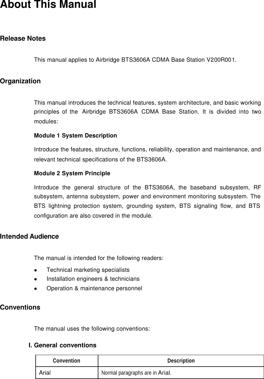
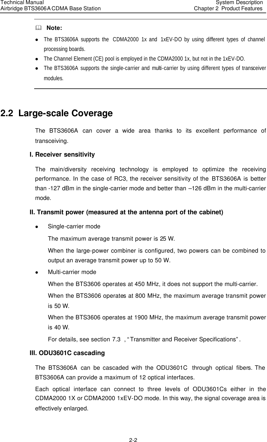
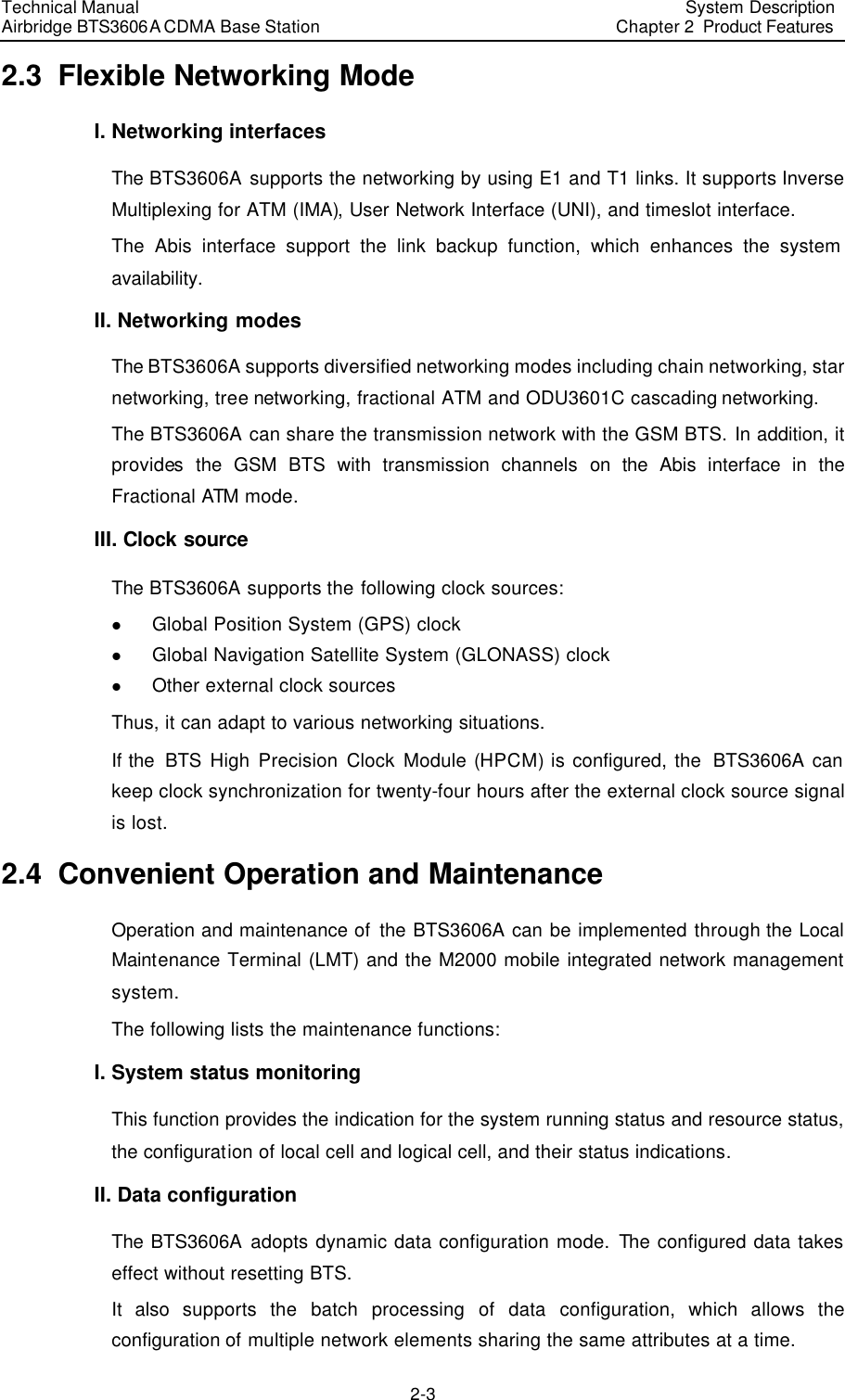
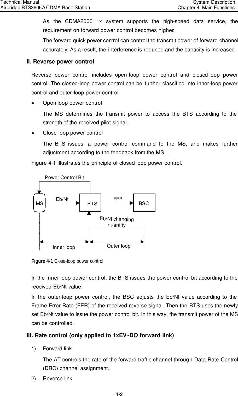
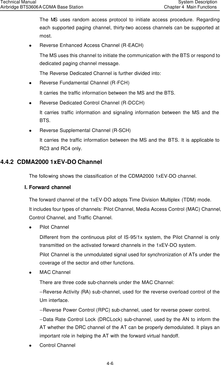
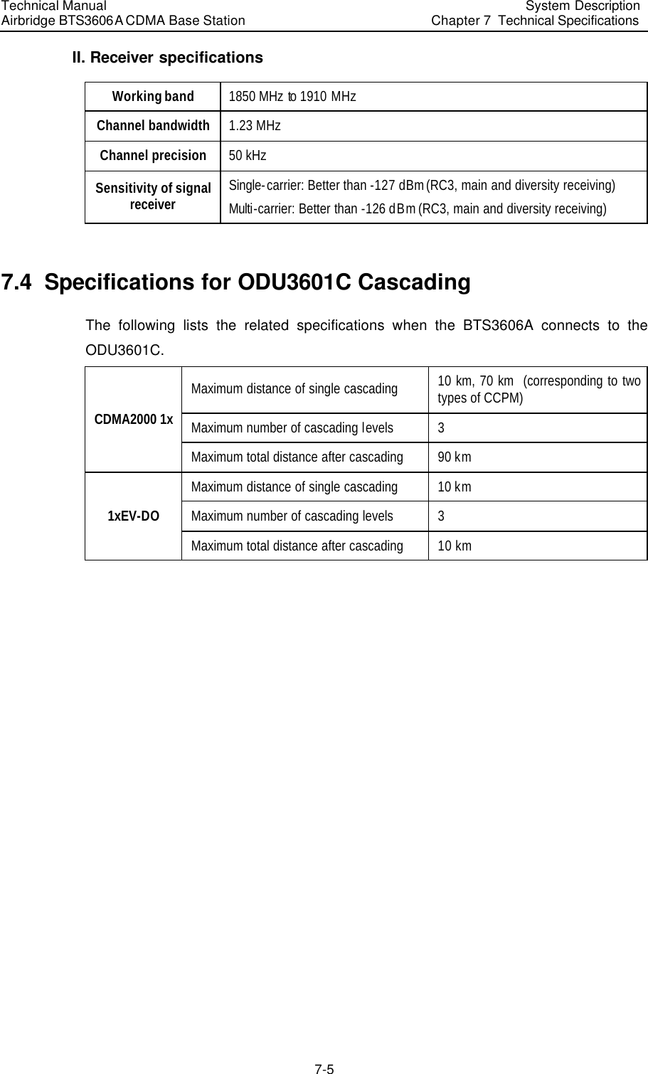
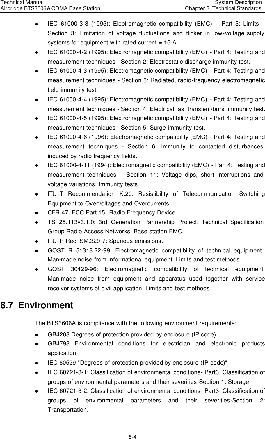
![Convention Description Arial Narrow Warnings, Cautions, Notes and Tips are in Arial Narrow. Boldface Headings are in Boldface. Courier New Terminal Display is in Courier New. II. Command conventions Convention Description Boldface The keywords of a command line are in Boldface. italic Command arguments are in italic. [ ] Items (keywords or arguments) in square brackets [ ] are optional. { x | y | ... } Alternative items are grouped in braces and separated by vertical bars. One is selected. [ x | y | ... ] Optional alternative items are grouped in square brackets and separated by vertical bars. One or none is selected. { x | y | ... } * Alternative items are grouped in braces and separated by vertical bars. A minimum of one or a maximum of all can be selected. [ x | y | ... ] * Optional alternative items are grouped in square brackets and separated by vertical bars. Many or none can be selected. III. GUI conventions Convention Description < > Button names are inside angle brackets. For example, click the <OK> button. [ ] Window names, menu items, data table and field names are inside square brackets. For example, pop up the [New User] window. / Multi-level menus are separated by forward slashes. For example, [File/Create/Folder]. IV. Keyboard operation Format Description <Key> Press the key with the key name inside angle brackets. For example, <Enter>, <Tab>, <Backspace>, or <A>. <Key1+Key2> Press the keys concurrently. For example, <Ctrl+Alt+A> means the three keys should be pressed concurrently.](https://usermanual.wiki/Huawei-Technologies/BTS3606A-1900/User-Guide-447491-Page-5.png)