Huawei Technologies BTS3606A-1900 CDMA Base Station User Manual
Huawei Technologies Co.,Ltd CDMA Base Station Users Manual
Users Manual
HUAWEI
1. System Description
2. System Principle
Airbridge BTS3606A CDMA Base Station
Technical Manual
V200R001

Airbridge BTS3606A CDMA Base Station
Technical Manual
Manual Version T2-030266-20040602-C-2.10
Product Version V200R001
BOM 31026366
Huawei Technologies Co., Ltd. provides customers with comprehensive technical support
and service. Please feel free to contact our local office or company headquarters.
Huawei Technologies Co., Ltd.
Address: Administration Building, Huawei Technologies Co., Ltd.,
Bantian, Longgang District, Shenzhen, P. R. China
Postal Code: 518129
Website: http://www.huawei.com
Email: support@huawei.com

Copyright © 2004 Huawei Technologies Co., Ltd.
All Rights Reserved
No part of this manual may be reproduced or transmitted in any form or by any
means without prior written consent of Huawei Technologies Co., Ltd.
Trademarks
, HUAWEI, C&C08, EAST8000, HONET, , ViewPoint, INtess, ETS, DMC,
TELLIN, InfoLink, Netkey, Quidway, SYNLOCK, Radium, M900/M1800,
TELESIGHT, Quidview, Musa, Airbridge, Tellwin, Inmedia, VRP, DOPRA, iTELLIN,
HUAWEI OptiX, C&C08 iNET, NETENGINE, OptiX, iSite, U-SYS, iMUSE, OpenEye,
Lansway, SmartAX, infoX, TopEng are trademarks of Huawei Technologies Co.,
Ltd.
All other trademarks mentioned in this manual are the property of their respective
holders.
Notice
The information in this manual is subject to change without notice. Every effort has
been made in the preparation of this manual to ensure accuracy of the contents, but
all statements, information, and recommendations in this manual do not constitute
the warranty of any kind, express or implied.

About This Manual
Release Notes
This manual applies to Airbridge BTS3606A CDMA Base Station V200R001.
Organization
This manual introduces the technical features, system architecture, and basic working
principles of the Airbridge BTS3606A CDMA Base Station. It is divided into two
modules:
Module 1 System Description
Introduce the features, structure, functions, reliability, operation and maintenance, and
relevant technical specifications of the BTS3606A.
Module 2 System Principle
Introduce the general structure of the BTS3606A, the baseband subsystem, RF
subsystem, antenna subsystem, power and environment monitoring subsystem. The
BTS lightning protection system, grounding system, BTS signaling flow, and BTS
configuration are also covered in the module.
Intended Audience
The manual is intended for the following readers:
l Technical marketing specialists
l Installation engineers & technicians
l Operation & maintenance personnel
Conventions
The manual uses the following conventions:
I. General conventions
Convention Description
Arial Normal paragraphs are in Arial.

Convention Description
Arial Narrow Warnings, Cautions, Notes and Tips are in Arial Narrow.
Boldface Headings are in Boldface.
Courier New Terminal Display is in Courier New.
II. Command conventions
Convention Description
Boldface The keywords of a command line are in Boldface.
italic Command arguments are in italic.
[ ] Items (keywords or arguments) in square brackets [ ] are optional.
{ x | y | ... } Alternative items are grouped in braces and separated by vertical bars.
One is selected.
[ x | y | ... ] Optional alternative items are grouped in square brackets and separated
by vertical bars. One or none is selected.
{ x | y | ... } * Alternative items are grouped in braces and separated by vertical bars. A
minimum of one or a maximum of all can be selected.
[ x | y | ... ] * Optional alternative items are grouped in square brackets and separated
by vertical bars. Many or none can be selected.
III. GUI conventions
Convention Description
< > Button names are inside angle brackets. For example, click the <OK>
button.
[ ] Window names, menu items, data table and field names are inside square
brackets. For example, pop up the [New User] window.
/ Multi-level menus are separated by forward slashes. For example,
[File/Create/Folder].
IV. Keyboard operation
Format Description
<Key> Press the key with the key name inside angle brackets. For example,
<Enter>, <Tab>, <Backspace>, or <A>.
<Key1+Key2> Press the keys concurrently. For example, <Ctrl+Alt+A> means the three
keys should be pressed concurrently.

Format Description
<Key1, Key2> Press the keys in turn. For example, <Alt, A> means the two keys should
be pressed in turn.
V. Mouse operation
Action Description
Click Press the left button or right button quickly (left button by default).
Double Click Press the left button twice continuously and quickly.
Drag Press and hold the left button and drag it to a certain position.
VI. Symbols
Eye-catching symbols are also used in the manual to highlight the points worthy of
special attention during the operation. They are defined as follows:
Caution, Warning, Danger: Means reader be extremely careful during the
operation.
& Note, Comment, Tip, Knowhow, Thought: Means a complementary description.

Technical Manual
Airbridge BTS3606A CDMA Base Station System Description
Table of Contents
i
Table of Contents
Chapter 1 Introduction .........................................................................................................1-1
1.1 Comparison between CDMA2000 1x and 1xEV-DO.....................................................1-1
1.2 Huawei CDMA2000 1x / 1xEV-DO Hybrid Network Solution .........................................1-2
1.2.1 Brief Introduction to BSS/AN.............................................................................1-3
1.2.2 Brief Introduction to CN....................................................................................1-4
1.3 Position of BTS3606A ................................................................................................1-5
Chapter 2 Product Features.................................................................................................2-1
2.1 Technical Features ....................................................................................................2-1
2.2 Large-scale Coverage................................................................................................2-2
2.3 Flexible Networking Mode..........................................................................................2-3
2.4 Convenient Operation and Maintenance......................................................................2-3
2.5 Powerful Environment Adaptability..............................................................................2-5
2.6 Easy Upgrade and Expansion ....................................................................................2-6
2.7 Serial Products for Seamless Coverage......................................................................2-6
Chapter 3 Product Architecture............................................................................................3-1
3.1 Cabinet Physical Features..........................................................................................3-1
3.2 Cabinet Configuration ................................................................................................3-2
3.3 System Structure.......................................................................................................3-3
3.3.1 Baseband Subsystem ......................................................................................3-4
3.3.2 RF Subsystem.................................................................................................3-4
3.3.3 Antenna Subsystem.........................................................................................3-5
3.3.4 Power Supply and Environment Monitoring Subsystem......................................3-5
3.4 Physical Interface......................................................................................................3-6
Chapter 4 Main Functions....................................................................................................4-1
4.1 Power Control and Rate Control .................................................................................4-1
4.2 Handoff.....................................................................................................................4-3
4.3 Radio Configuration ...................................................................................................4-4
4.4 Channel Configuration ...............................................................................................4-4
4.4.1 CDMA2000 1x Channel....................................................................................4-4
4.4.2 CDMA2000 1xEV-DO Channel .........................................................................4-6
4.5 Multi-carrier...............................................................................................................4-8
4.6 Receiving Diversity....................................................................................................4-8
4.7 Cell Breathing............................................................................................................4-8
Chapter 5 Reliability Design .................................................................................................5-1
5.1 System Reliability ......................................................................................................5-1
5.2 Hardware Reliability...................................................................................................5-2

Technical Manual
Airbridge BTS3606A CDMA Base Station System Description
Table of Contents
ii
5.3 Software Reliability ....................................................................................................5-4
Chapter 6 Operation and Maintenance System ....................................................................6-1
6.1 Structure of the Operation and Maintenance System....................................................6-1
6.1.1 Local Operation and Maintenance System.........................................................6-1
6.1.2 Mobile Integrated Network Management System ...............................................6-2
6.2 Operation and Maintenance Function..........................................................................6-3
Chapter 7 Technical Specifications......................................................................................7-1
7.1 Structure and Environment Specifications ...................................................................7-1
7.2 Capacity Specifications ..............................................................................................7-2
7.3 Transmitter and Receiver Specifications......................................................................7-3
7.3.1 Transmitter and Receiver Specifications at 450 MHz Band.................................7-3
7.3.2 Transmitter and Receiver Specifications at 800 MHz Band.................................7-4
7.3.3 Transmitter and Receiver Specifications at 1900 MHz Band ...............................7-4
7.4 Specifications for ODU3601C Cascading ....................................................................7-5
Chapter 8 Technical Standards............................................................................................8-1
8.1 General Technical Specifications ................................................................................8-1
8.2 Um Interface .............................................................................................................8-1
8.3 Abis Interface............................................................................................................8-1
8.4 Lightning Protection ...................................................................................................8-2
8.5 Safety.......................................................................................................................8-3
8.6 EMC.........................................................................................................................8-3
8.7 Environment ..............................................................................................................8-4
Chapter 9 Abbreviations and Acronyms..............................................................................9-1

Technical Manual
Airbridge BTS3606A CDMA Base Station System Description
List of Figures
iii
List of Figures
Figure 1-1 Structure of Huawei CDMA2000 1x / 1xEV-DO hybrid network .........................1-2
Figure 3-1 BTS3606A cabinet ........................................................................................3-1
Figure 3-2 A fully equipped BTS3606A cabinet................................................................3-2
Figure 3-3 BTS3606A system structure...........................................................................3-4
Figure 4-1 Close-loop power control ...............................................................................4-2
Figure 6-1 BSS/AN local operation and maintenance system ...........................................6-1
Figure 6-2 Networking of M2000 mobile integrated network management system..............6-3

Technical Manual
Airbridge BTS3606A CDMA Base Station System Description
List of Tables
iv
List of Tables
Table 1-1 Comparison between CDMA2000 1x and 1xEV-DO ..........................................1-1
Table 2-1 Application comparison among serial BTS products ..........................................2-7
Table 3-1 Boards and modules of the BTS3606A .............................................................3-2

Technical Manual
Airbridge BTS3606A CDMA Base Station System Description
Chapter 1 Introduction
1-1
Chapter 1 Introduction
The mobile communication system has experienced the first generation (analog
system) and the second generation (digital system).
As one of the main development trends of the second generation, the Code Division
Multiple Access 1 Carrier (CDMA2000 1x) technology, advocated by the 3rd Generation
Partnership Project 2 (3GPP2), has been widely used for commercial purpose.
The CDMA2000 1x technology is compatible with IS-95A and IS-95B standards. The
capacity of the CDMA2000 1x system increases substantially thanks to technologies
such as reverse pilot, fast power control and transmits diversity.
As the evolution of the CDMA2000 1x, 1xEV-DO (EVolution-Data Optimized) can
provides a peak forward data rate at 2.4 Mbps and a peak reverse data rate at 153.6
kbps. It can deliver diversified radio data services such as multi-media gaming,
multi-media news, real-time video traffic news, video phone, video conference,
real-time security information, and location-base services.
This chapter provides the compassion between the CDMA2000 1x and the 1xEV-DO
technologies, and introduces the network solution of Huawei CDMA2000 1x / 1xEV-DO
hybrid mobile communication system and the position of BTS3606A in this solution.
1.1 Comparison between CDMA2000 1x and 1xEV-DO
The BTS3606A supports both CDMA2000 1x and 1xEV-DO.
Table 1-1 exams the differences between them.
Table 1-1 Comparison between CDMA2000 1x and 1xEV-DO
Item CDMA2000 1x 1xEV-DO
Peak data
rate
Forward (RC3): 153.6 kbps
Reverse (RC3): 153.6 kbps
Forward: 2.4 Mbps
Reverse: 153.6 kbps
Code Convolutional code and Turbo code Turbo code
Modulation
Reverse: Hybrid Phase Shift Keying
(HPSK)
Forward: Quadrature Phase Shift Keying
(QPSK)
Reverse: HPSK
Forward: QPSK, 8-Phase Shift Keying
(8-PSK), 16- Quadrature Amplitude
Modulation (16-QAM)
Handoff Forward: Soft handoff and hard handoff
Reverse: Soft handoff and hard handoff.
Forward: Virtual soft handoff
Reverse: Soft handoff
Rate/power
control
Forward: Power control
Reverse: Power control
Forward: Rate control
Reverse: Rate control and power control
Technical Manual
Airbridge BTS3606A CDMA Base Station System Description
Chapter 1 Introduction
1-2
Item CDMA2000 1x 1xEV-DO
Channel
multiplex
mode
Forward: Code Division Multiplex (CDM)
Reverse: Code division multiplex
Forward: Time Division Multiplex (TDM)
and code division multiplex
Reverse: Code division multiplex
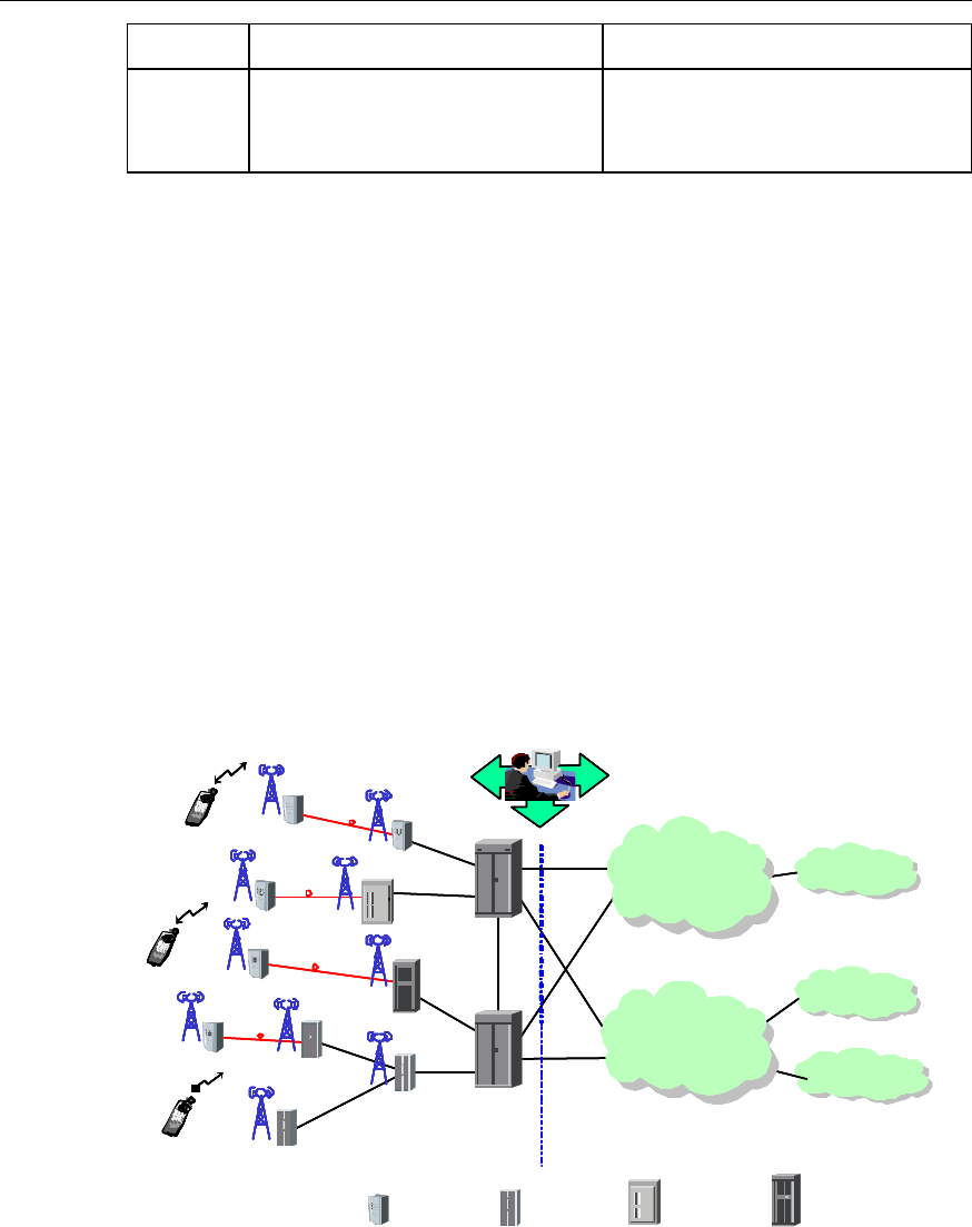
1.2 Huawei CDMA2000 1x / 1xEV-DO Hybrid Network
Solution
The Huawei CDMA2000 1x / 1xEV-DO hybrid mobile communication system
comprises the Base Station Subsystem/Access Network (BSS/AN) and the Core
Network (CN).
The operation and maintenance of the system is implemented through an integrated
mobile network management system.
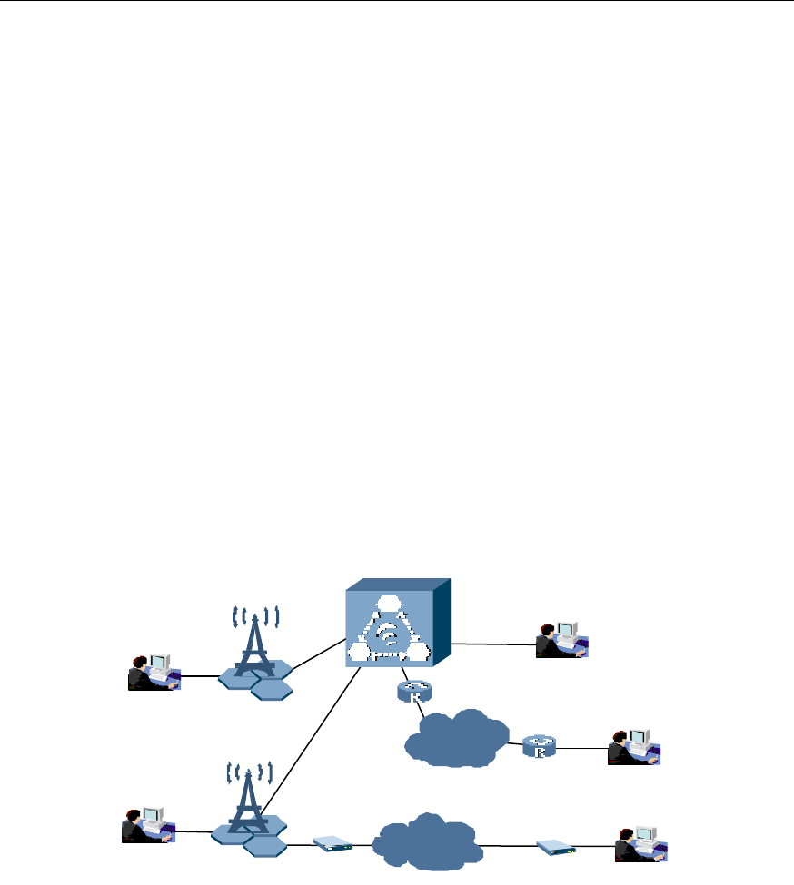
Figure 1-1 shows the network structure of Huawei CDMA2000 1x / 1xEV-DO hybrid
system.
As this manual aims to introduce the BTS3606A of the BSS/AN, the following figure
emphasizes the network structure of the BSS/AN.
Mobile Network
Management System
Internet
PSTN/ISDN
PLMN
A3/A7
A1/A2
A10/A11
Abis
A1/A2
BSC/PCF
BSC/PCF
MS
A10/A11
Abis
Abis
BSS / AN CN
BTS
Abis
BTS
BTS
BTS
BTS
BTS
ODU
ODU
ODU
ODU
MS/AT
BTS3601C/ODU3601C BTS3606 cBTS3612BTS3612A/BTS3606A
Optical fiber
MS/AT
Packet Domain
Network Equipment
Circuit Domain
Network Equipment
Internet
PSTN/ISDN
PLMNPLMNPLMN
A3/A7
A1/A2
A10/A11
Abis
A1/A2
BSC/PCF
BSC/PCF
MSMS
A10/A11
Abis
Abis
BSS / AN CN
BTS
Abis
BTSBTS
BTSBTS
BTSBTS
BTSBTS
BTSBTS
ODUODU
ODUODU
ODUODU
ODUODU
MS/AT
BTS3601C/ODU3601C BTS3606 cBTS3612BTS3612A/BTS3606A
Optical fiber
MS/AT
Packet Domain
Network Equipment
Circuit Domain
Network Equipment
MS: Mobile Station BTS: Base Transceiver Station
ODU: Out Door Unit BSC: Base Station Controller
PCF: Packet Control Function BSS: Base Station Subsystem
CN: Core Network PLMN: Public Land Mobile Network
AN: Access Network ISDN: Integrated Service Digital Network
AT: Access Terminal PSTN: Public Service Telephone Network
Figure 1-1 Structure of Huawei CDMA2000 1x / 1xEV-DO hybrid network

Technical Manual
Airbridge BTS3606A CDMA Base Station System Description
Chapter 1 Introduction
1-3
&
Note:
The appearance of the BTS3601C cabinet is the same as the ODU3601C cabinet.
1.2.1 Brief Introduction to BSS/AN
The BSS is a concept used in the CDMA2000 1x network. It consists of the Base
Transceiver Station (BTS), Base Station Controller (BSC), and Packet Control Function
(PCF). The PCF is usually integrated with the BSC. The ODU3601C, a soft BTS, is also
a part of the Huawei BSS.
The AN is a concept used in the 1xEV-DO network. It consists of the 1xEV-DO BTS and
BSC (integrated with PCF).
I. BTS
The BTS transmits and receives radio signals to enable the communication between
the radio network system and the Mobile Station/Access Terminal (MS/AT). Huawei
provides a series of BTS products, including:
l BTS3606A: Outdoor BTS equipment supporting the CDMA2000 1x and
CDMA2000 1xEV-DO standards. The maximum capacity of a single cabinet is six
sector carriers. With the multi-carrier technology, the BTS3606A can support a
maximum of 18 sector carriers.
l BTS3606: Indoor BTS equipment supporting the CDMA2000 1x and CDMA2000
1xEV-DO standards. The maximum capacity of a single cabinet is six sector
carriers. With the multi-carrier technology, the BTS3606 can support a maximum
of 18 sector carriers.
l cBTS3612: Indoor BTS equipment supporting both the CDMA2000 1x and
1xEV-DO standards. The maximum capacity of a single cabinet is 12 sector
carriers.
l BTS3612A: Outdoor BTS equipment supporting both the CDMA2000 1x and
1xEV-DO standards. The maximum capacity of a single cabinet is six sector
carriers.
l BTS3601C: Outdoor one-carrier BTS equipment supporting the CDMA2000 1x
standard.
l ODU3601C: Outdoor one-carrier soft BTS equipment supporting the CDMA2000
1x standard. It shares the baseband processing resource of its upper-level BTS. It
also transmits and receives the radio signals together with the upper-level BTS.
II. BSC/PCF
The BSC performs the following functions:
l BTS control and management
l Call connection and disconnection

Technical Manual
Airbridge BTS3606A CDMA Base Station System Description
Chapter 1 Introduction
1-4
l Mobility management
l Power control
l Radio resource management
l Provision of stable and reliable radio connections for the upper-level services
through soft/hard handoff
The PCF manages the Radio-Packet (R-P) connection. As radio resources are limited,
they should be released when subscribers are not sending or receiving any information.
But the Peer-Peer Protocol (PPP) connection must be maintained. The PCF shields the
radio mobility from the upper-level services through the handoff function.
III. MS/AT
l MS
MS is the equipment used by the mobile subscriber. It can originate and receive
calls, and communicate with the BSS.
l AT
AT is a device with a radio modem and a data interface that allows the user to
access a packet data network through the 1xEV-DO Access Network.
An AT is analogous to a mobile station in an CDMA2000 1x system. It may be
connected to a computing device like a laptop computer or may be a
self-contained data device like a Personal Digital Assistant (PDA).
1.2.2 Brief Introduction to CN
The CN comprises the packet domain network and the circuit domain network.
I. Packet domain network equipment
The packet domain network equipment covers
l Packet Data Service Node (PDSN)
l Mobile Internet Protocol Home Agent (MIP HA)
l Authorization, Authentication and Accounting (AAA)
They connect to and communicate with the Internet.
II. Circuit domain network equipment
The circuit domain network equipment includes
l Mobile Switching Center (MSC)
l Home Location Register (HLR)
l Gateway Mobile-services Switching Center (GMSC).
They connect to and communicate with the conventional Public Land Mobile Network
(PLMN) and Public Switched Telephone Network/Integrated Services Digital Network
(PSTN/ISDN).

Technical Manual
Airbridge BTS3606A CDMA Base Station System Description
Chapter 1 Introduction
1-5
1.3 Position of BTS3606A
The following examines the position of the BTS3606A in the network and in the
application.
I. Position in the network
The BTS3606A is located between the BSC and the MS/AT in the CDMA2000 1x /
1xEV-DO hybrid system. Under the control of the BSC, the BTS3606A is the radio
transceiver equipment serving one cell or multiple logical sectors.
Connecting with the BSC through the Abis interface, the BTS3606A helps the BSC
manage radio resources, radio parameters and interfaces. It also implements, over the
Um interface, the radio transmission between the BTS and the MS, as well as related
control functions.
II. Position in the application
The BTS3606A is an outdoor BTS. It can adapt to the sophisticated natural and
electromagnetic environment.
The BTS3606A features lower cost, fast deployment, and strong environment
adaptability. It facilitates the seamless coverage of the radio network.
The BTS3606A is suitable for the area with medium or large traffic.
Fully compatible with CDMA2000 1x and 1xEV-DO, the BTS3606A can work in the
CDAM2000 1x mode, the 1xEV-DO mode, or the CDMA2000 1x / 1xEV-DO hybrid
mode.

Technical Manual
Airbridge BTS3606A CDMA Base Station System Description
Chapter 2 Product Features
2-1
Chapter 2 Product Features
The BTS3606A is designed in consideration of customers' requirements for service,
capacity, coverage, transmission, power supply, installation and maintenance. It
employs integrated design, which shows the customer-oriented service idea of Huawei.
2.1 Technical Features
The BTS3606A has the following technical features:
l Support both the CDMA2000 1x and 1xEV-DO standards.
l Support the CDMA2000 1x / 1xEV-DO hybrid networking. The CDMA2000 1x and
CDMA2000 1xEV-DO carriers can be configured at any ratio.
l Allow the coexistence of the single-carrier and multi-carrier modules.
l Provide powerful sector processing capability and support the large-power
coverage of a single sector or large-capacity coverage of multiple carriers.
l Adopt resource pool design to improve the hardware resource utilization ratio and
the system error tolerance capability.
l Adopt the digital Intermediate Frequency (IF) technology to improve the system
availability.
l Adopt intelligent fan control to increase the service life of fans and reduce the
noise.
l Support anti-interference for inband adaptive wave filtering (applicable to the case
of a single carrier)
l Work on such bands as 450 MHz, 800 MHz and 1900 MHz.
l Support cascading with the ODU3601C to expand the coverage area of radio
network flexibly.
l Support forward/reverse load control and access channel load control to ensure
the system capacity and the service quality.
l Support various service negotiations, including active negotiations, passive
negotiations, or non- negotiations.
l Support Push To Talk (PTT) function.
l Support the coexistence of modules of multiple bands.

Technical Manual
Airbridge BTS3606A CDMA Base Station System Description
Chapter 2 Product Features
2-2
&
Note:
l The BTS3606A supports the CDMA2000 1x and 1xEV-DO by using different types of channel
processing boards.
l The Channel Element (CE) pool is employed in the CDMA2000 1x, but not in the 1xEV-DO.
l The BTS3606A supports the single-carrier and multi-carrier by using different types of transceiver
modules.
2.2 Large-scale Coverage
The BTS3606A can cover a wide area thanks to its excellent performance of
transceiving.
I. Receiver sensitivity
The main/diversity receiving technology is employed to optimize the receiving
performance. In the case of RC3, the receiver sensitivity of the BTS3606A is better
than -127 dBm in the single-carrier mode and better than –126 dBm in the multi-carrier
mode.
II. Transmit power (measured at the antenna port of the cabinet)
l Single-carrier mode
The maximum average transmit power is 25 W.
When the large-power combiner is configured, two powers can be combined to
output an average transmit power up to 50 W.
l Multi-carrier mode
When the BTS3606 operates at 450 MHz, it does not support the multi-carrier.
When the BTS3606 operates at 800 MHz, the maximum average transmit power
is 50 W.
When the BTS3606 operates at 1900 MHz, the maximum average transmit power
is 40 W.
For details, see section 7.3 , “Transmitter and Receiver Specifications”.
III. ODU3601C cascading
The BTS3606A can be cascaded with the ODU3601C through optical fibers. The
BTS3606A can provide a maximum of 12 optical interfaces.
Each optical interface can connect to three levels of ODU3601Cs either in the
CDMA2000 1X or CDMA2000 1xEV-DO mode. In this way, the signal coverage area is
effectively enlarged.

Technical Manual
Airbridge BTS3606A CDMA Base Station System Description
Chapter 2 Product Features
2-3
2.3 Flexible Networking Mode
I. Networking interfaces
The BTS3606A supports the networking by using E1 and T1 links. It supports Inverse
Multiplexing for ATM (IMA), User Network Interface (UNI), and timeslot interface.
The Abis interface support the link backup function, which enhances the system
availability.
II. Networking modes
The BTS3606A supports diversified networking modes including chain networking, star
networking, tree networking, fractional ATM and ODU3601C cascading networking.
The BTS3606A can share the transmission network with the GSM BTS. In addition, it
provides the GSM BTS with transmission channels on the Abis interface in the
Fractional ATM mode.
III. Clock source
The BTS3606A supports the following clock sources:
l Global Position System (GPS) clock
l Global Navigation Satellite System (GLONASS) clock
l Other external clock sources
Thus, it can adapt to various networking situations.
If the BTS High Precision Clock Module (HPCM) is configured, the BTS3606A can
keep clock synchronization for twenty-four hours after the external clock source signal
is lost.
2.4 Convenient Operation and Maintenance
Operation and maintenance of the BTS3606A can be implemented through the Local
Maintenance Terminal (LMT) and the M2000 mobile integrated network management
system.
The following lists the maintenance functions:
I. System status monitoring
This function provides the indication for the system running status and resource status,
the configuration of local cell and logical cell, and their status indications.
II. Data configuration
The BTS3606A adopts dynamic data configuration mode. The configured data takes
effect without resetting BTS.
It also supports the batch processing of data configuration, which allows the
configuration of multiple network elements sharing the same attributes at a time.

Technical Manual
Airbridge BTS3606A CDMA Base Station System Description
Chapter 2 Product Features
2-4
The data backup function is also available.
III. Alarm processing
This function involves:
l Alarm collection
l Alarm clearing
l Alarm querying
l Alarm shielding
l Alarm filtering
IV. Security management
The security management function includes:
l User login authentication
l Command authority restriction
l Confirmation of dangerous operation
l User group management
l Timeout locking
V. Test
The BTS3606A supports both offline and online tests. The test items include:
l Board loopback test
l Self-test
l Trunk loopback test
VI. Site monitoring
Data transmission channels are available for the monitoring equipment in the
equipment room to facilitate attendance-free and centralized monitoring of the
BTS3606A.
VII. Upgrade
Users can upgrade the system through remote loading. The upgrade process is
retrievable, that is, the system can back off to the original one when the upgrade fails.
VIII. Equipment operation
The BTS3606A supports front operation, and online insertion and removal of baseband
boards. This facilitates the maintenance, upgrade and expansion of the system.
IX. Auto restart function
When the BTS3606A is out of service owing to power failure or transmission failure, it
can restart automatically right after the faults are cleared.

Technical Manual
Airbridge BTS3606A CDMA Base Station System Description
Chapter 2 Product Features
2-5
X. Reverse maintenance function
With the reverse maintenance function, users can, from the LMT, log in to the BAM
through the network port on the BCKM to perform operation, maintenance and
management over the whole BSS.
2.5 Powerful Environment Adaptability
The BTS3606A is protected against wind, sand, rain, sun shine, and theft.
I. Totally-enclosed integrated structure
The water-proof and dust-proof measures of the BTS3606A are in compliance with the
International Protection (IP55) standard. The moisture-proof, mould-proof, and salt
fog-proof level reaches the Class 1 protection standard (3 classes).
&
Note:
For details a|bout the IP55, see GB4208: Enclosure Protection Level (IP Code) or IEC 60529: Degrees of
protection provided by enclosure (IP code).
II. Wide operating temperature range
The BTS3606A is equipped with a temperature control system.
The operating temperature of the BTS3606A with air conditioner is from –40°C to
+55°C. The operating temperature of the BTS3606A with heat exchanger is from
–40°C to +45°C.
In a high-temperature environment, the BTS3606A uses its temperature control unit to
dissipate heat. In a low-temperature environment, the built-in heater is activated to
ensure the internal components to operate in a reliable temperature range.
III. Robust power distribution function
The BTS3606A supports 220V, 230V and 240V power and single-phase/three-phase
input. The voltage ranges from 176 V to 264V and frequency from 47 Hz to 63 Hz. It
provides over-voltage protection when the voltage reaches 290 V.
The system is also compatible with 110 V AC, 115 V AC and 127 V AC power and
single-phase/three-phase input. The voltage ranges between 95 V to 135V and
frequency between 47 Hz to 63 Hz. It provides over-voltage protection when the
voltage reaches 85V.
The built-in battery provides power supply in the case of AC power failure to ensure the
normal operation of the BTS3606A for a period of time.

Technical Manual
Airbridge BTS3606A CDMA Base Station System Description
Chapter 2 Product Features
2-6
The optional outdoor battery cabinet allows a three-section-carrier system to operate
for more than eight hours when the AC power of the BTS is cut off.
The hierarchical power supply function of the BTS3606A can promise the transmission
function of lower-level BTSs in the absence of mains support.
IV. Sound lightning protection and monitoring function
The BTS3606A is equipped with reliable lightning protection facilities such as built-in
lightning protection board and external lightning protection box.
It is also furnished with comprehensive environment monitoring system to implement
remote monitoring.
2.6 Easy Upgrade and Expansion
I. Compatibility design
The BTS3606A is compatible with CDMA2000 1x and 1xEV-DO. It can be evolved to
1xEV-DV (EVolution-Data and Voice) smoothly.
The network can be upgraded from CDMA2000 1x to CDMA2000 1x EV-DO by
replacing the CCPM with CECM and upgrading the BTS software to protect the
operator's investment.
II. Flexible configuration
The BTS3606A supports the multi-cell configuration. When it is cascaded with
ODU3601C, the ODU3601C can be configured as an independent cell to realize the
flexible coverage.
The BTS3606A supports the omni cell and 3-sector configuration.
III. Smooth expansion
The modular structure allows the BTS3606A to be expanded simply by adding
modules.
With the multi-carrier technology, the capacity of a single-carrier BTS3606A cabinet
can be expanded from six sector carriers to eighteen sector carriers.
2.7 Serial Products for Seamless Coverage
Huawei provides a series of BTS products to enable a seamless coverage for urban,
suburb, and rural area, highway and hot area.
Table 2-1 shows the application of various BTS products.

Technical Manual
Airbridge BTS3606A CDMA Base Station System Description
Chapter 2 Product Features
2-7
Table 2-1 Application comparison among serial BTS products
Model Max. sector
carrier per
cabinet Capacity Application Type
Single-
carrier 6 Medium Medium and small cities,
towns. Low requirement for
equipment room.
Indoor BTS supporting
CDMA2000 1x and 1xEV-DO
BTS3606
Multi-
carrier 18 Large Highly populated area and
city
Indoor BTS supporting
CDMA2000 1x and 1xEV-DO
Single-
carrier 6 Medium Highly populated area and
city , medium and small cities
and towns.
Outdoor BTS supporting
CDMA2000 1x and 1xEV-DO
BTS3606A
Multi-
carrier 18 Large
High-traffic area and limited
equipment room space,
highly populated area and
city
Outdoor BTS supporting
CDMA2000 1x and 1xEV-DO
cBTS3612 12 Large Highly populated area and
city. Indoor BTS supporting both
CDMA2000 1x and 1xEV-DO
BTS3612A 6 Medium High-traffic area and limited
equipment room space
Outdoor BTS supporting both
CDMA2000 1x and 1xEV-DO
BTS3601C 1 Small Indoor, underground,
highway and railroad.
Outdoor BTS supporting
CDMA2000 1x (also applicable
to the indoor condition)
ODU3601C 1 Small Indoor, underground,
highway and railroad.
Outdoor BTS supporting
CDMA2000 1x (also applicable
to the indoor condition)
Technical Manual
Airbridge BTS3606A CDMA Base Station System Description
Chapter 3 Product Architecture
3-1
Chapter 3 Product Architecture
This chapter introduces the physical features and configuration of the BTS3606A.
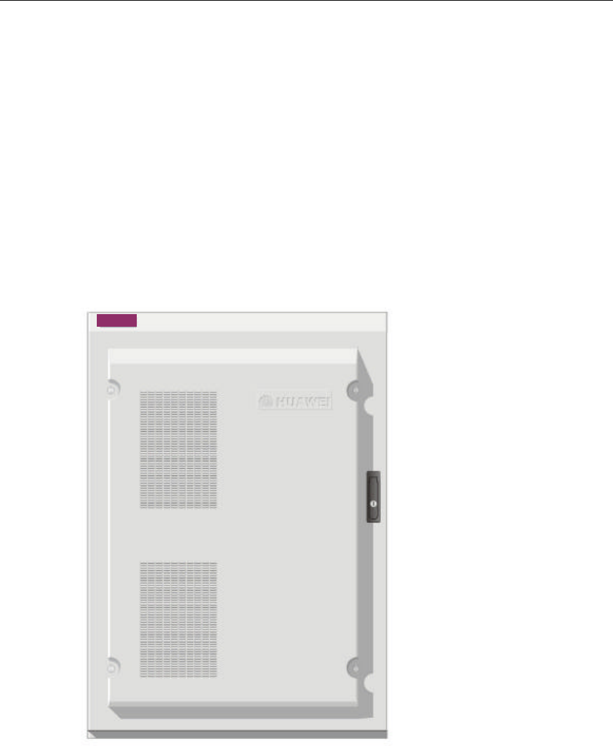
3.1 Cabinet Physical Features
The BTS3606A cabinet is designed in accordance with the IEC297 standard.
The outer dimensions are 1700 mm % 1200 mm % 1000 mm (Height % Width % Depth)
(excluding the components installed on the top of the cabinet).
Figure 3-1 shows the BTS3606A cabinet.
BTS3606ABTS3606A
Figure 3-1 BTS3606A cabinet
The BTS3606A cabinet has the following features:
l Total-enclosed integrated structure and power environment adaptively
l Light weight owing to its aluminum alloy materials
l Excellent electrical conductivity and shielding effect
l Good ventilation effect owing to its reasonable design of air ducts
l Easy installation and maintenance
Technical Manual
Airbridge BTS3606A CDMA Base Station System Description
Chapter 3 Product Architecture
3-2
l Nice appearance
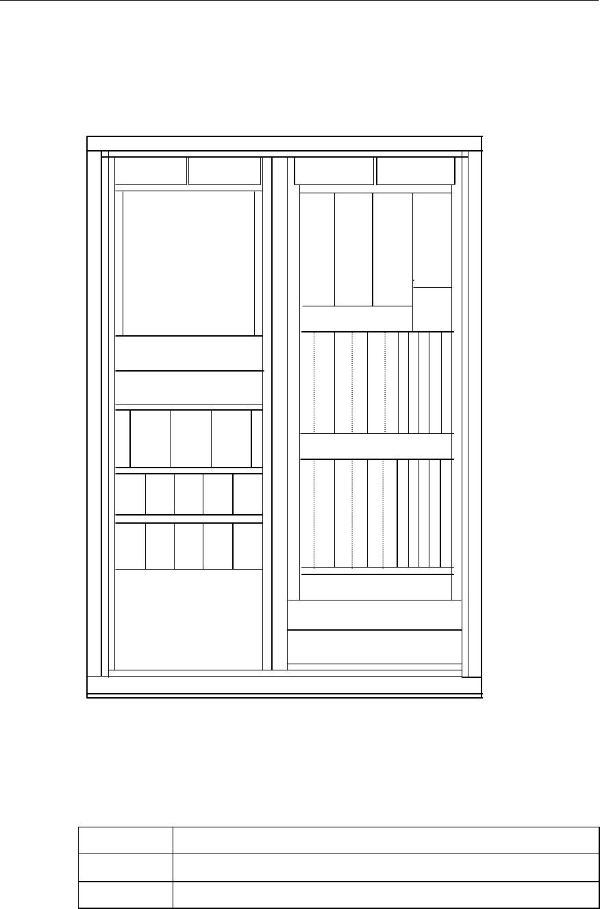
3.2 Cabinet Configuration
Figure 3-2 shows the configuration of the BTS3606A cabinet.
Battery or AC filter/DC lightning
arrester
Microwave/Other
Transimission Device
Fan box
Cable through
Cable inlet and AC lightning
PSU
(DC/DC) PSU
(DC/DC)
PSU
(AC/DC )
PMU
Secondary power
supply switch box
E1 or HDSL lightning
protection board
PSU
(DC/DC )
PSU
(AC/DC )
PSU
(AC/DC)
PSU
(AC/DC)
PSU
(AC/DC)
PSU
(AC/DC )
PSU
(AC/DC )
PSU
(AC/DC)
PSU
(AC/DC)
Air exhaust vent Air exhaust ventAir exhaust ventAir exhaust vent
C
H
P
A
1
C
T
R
M
1
C
H
P
A
3
C
T
R
M
3
C
H
P
A
5
C
T
R
M
5
C
H
P
A
0
C
T
R
M
0
C
H
P
A
2
C
T
R
M
2
C
H
P
A
4
C
T
R
M
4
CDDU
0CDDU
1CDDU
2
+27V
PDU
C
C
P
M
4
C
C
P
M
2
C
C
P
M
0
C
C
P
M
5
C
C
P
M
3
C
C
P
M
1
B
C
K
M
0
B
C
I
M
0
B
C
K
M
1
Cable through
Cable through
AC distribution box/Filter unit
Figure 3-2 A fully equipped BTS3606A cabinet
Table 3-1 lists the boards and modules of the BTS3606A.
Table 3-1 Boards and modules of the BTS3606A
Acronyms Full name
BCIM BTS Control Interface Module
BCKM BTS Control & Clock Module

Technical Manual
Airbridge BTS3606A CDMA Base Station System Description
Chapter 3 Product Architecture
3-3
Acronyms Full name
CCPM Compact-BTS Channel Process Module
CECM Compact-BTS EVDO Channel Module
CDDU Compact-BTS Dual Duplexer Unit
CHPA Compact-BTS High power Amplifier
CPCM Compact-BTS Power Combination Module
CTRM Compact-BTS Transceiver Module
CMTR Compact-BTS Multi-carrier Transceiver Module
CMPA Compact-BTS Multi-carrier Power Amplifier
PSUAC/DC AC/DC Power Supply Unit
PSUDC/DC DC/DC Power Supply Unit
PMU Power Management Unit
&
Note:
l The BTS3606A adopts the CCPM to support CDMA2000 1x, and the CECM to support 1xEV-DO.
l The same BTS3606A cabinet can be configured with CCPM and CECM, that is, the BTS3606A can
simultaneously support CDMA2000 1x and 1xEV-DO.
l The CPCM supports the power combination when the BTS3606 operates at 1900 MHz.
l CTRM and CHPA support the multi-carrier application.
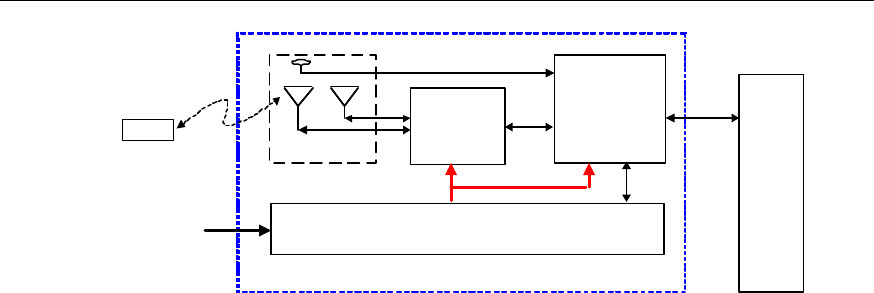
3.3 System Structure
The BTS3606A system consists of baseband subsystem, Radio Frequency (RF)
subsystem, power supply subsystem, and antenna subsystem.
Space is also reserved in the BTS3606A cabinet to hold the transmission equipment
such as the micro wave equipment and SDH equipment to support flexible
transmission access mode.
Figure 3-3 shows the structure of the BTS3606A.
Technical Manual
Airbridge BTS3606A CDMA Base Station System Description
Chapter 3 Product Architecture
3-4
BSC
Baseband subsystem
Power supply and environment monitoring subsystem
RF subsystem
Abis
interface
Um interface
MS/AT
Antenna subsystem
220 V AC
or 110 V AC
BTS3606A
Figure 3-3 BTS3606A system structure
3.3.1 Baseband Subsystem
The baseband subsystem comprises the BCKM, BCIM, CCPM, CECM, and HPCM. It
has the following functions:
l Provide Abis interface to process the Abis interface protocol.
l Provide a fiber interface to the RF subsystem to process the Um physical layer
and Common Channel (CCH) MAC layer protocols.
l Implement modulation/demodulation of CDMA2000 1x and 1xEV-DO baseband
data and the coding/decoding of CDMA channels.
l Provide synchronization clock signal to the BTS.
l Perform system resource management, operation and maintenance, and
environment monitoring.
3.3.2 RF Subsystem
The RF subsystem consists of the CTRM, CHPA, CDDU, and CPCM. It has the
following functions:
I. On the forward link
The RF subsystem
1) Performs power-adjustable up-conversion and linear power amplification on the
modulated transmit signals.
2) Completes power combination (optional).
3) Filters the transmit signals.
4) Finally sends the signals to the antenna subsystem.
II. On the reverse link
The RF subsystem
1) Filters the signals received by the BTS antenna to suppress the out-band
interference.
2) Performs low-noise amplification.

Technical Manual
Airbridge BTS3606A CDMA Base Station System Description
Chapter 3 Product Architecture
3-5
3) Performs noise factor–adjustable down-conversion, and channel-selective
filtering.
4) Finally sends the signals to the baseband subsystem.
3.3.3 Antenna Subsystem
The antenna subsystem of the BTS3606A includes the RF antenna and the satellite
synchronization antenna.
l RF antenna
This part covers the transmitting and receiving antennas, feeders, antenna
lightning arrester (optional), and tower mounted amplifier (optional). It transmits
and receives signals on the Um interface.
l Satellite synchronization antenna
This part includes the satellite signal receiving antenna, feeder, and lightning
arrester. It receives synchronization signals from the satellites (GPS or GLONASS)
to provide precise clock source for the BTS.
3.3.4 Power Supply and Environment Monitoring Subsystem
The power supply and environment monitoring subsystem includes the power supply,
environment monitoring part, and the temperature controller.
l Power supply
The power supply consists of:
--AC distribution unit
--DC distribution unit
--Power Supply Units (PSUs, including PSUAC/DC and PSUDC/DC)
--Power Management Unit (PMU)
--Battery group
--Management unit of the battery group
The PSUs work in N+1 redundancy mode. If any PSU fails, an alarm will be
reported. The PSUs support online insertion and removal.
l Environment monitoring part
The environment monitoring part includes the PMU and sensors. The PMU
collects the environment variables such as temperature, humidity, smoke, water
and access control from the sensors, and reports them to the BCKM of the BTS.
Based on the preset configuration, the BTS performs operations and reports the
information to the OMC.
l Temperature controller

Technical Manual
Airbridge BTS3606A CDMA Base Station System Description
Chapter 3 Product Architecture
3-6
The temperature controller may be an air conditioner or a heat exchanger, which
can ensure the normal operation of the BTS in the following ambient-temperature
ranges:
--Air conditioner: –40°C to 55°C
--Heat exchanger: –40°C to 45°C
3.4 Physical Interface
Interface Type Quantity Function
Abis interface E1 or T1 8
These interfaces connect to the transmission system that
connects to the BSC. Support IMA/UNI, cascading, and ATM over
Fractional ATM function.
When E1 is selected, 75W and 120W load interfaces are
available.
When T1 is selected, the 100W load interface is available.
ODU3601C
cascading
interface
Optical fiber 8 One CCPM/CECM can provide two optical interfaces. When it is
necessary to connect the BTS3606A to the ODU3601C, up to
three levels of ODU3601Cs can be connected.
GPS/GLONASS 2 Connect to the satellite receiver and satellite synchronization
antenna to provide long-term stable clock signals.
Clock interface External
synchronization
clock input
1 Provide high-precision clock when the GPS/GLONASS clock
signals are unavailable.
Maintenance
interface
Ethernet
interface 1 Provide local maintenance path.
Reference clock
interface 1 Output 10 MHz signals for test purpose.
Clock test
interface Synchronization
test interface 1 Output PP2S signals for test purpose.
Power supply
interface 4 Respectively connect to A, B, C, and N lines.
PGND interface 2 Respectively connect to grounding cable, and to the auxiliary
equipment.
Power supply
and Protection
Ground (PGND)
interface
DC interface 2 Connect to the –48V DC power supply that is used to charge the
batteries.
Antenna
interface RF signal 6 When three sectors are configured, each sector corresponds to
two DIN connectors, which can be used for both transmitting and
receiving.
Environment
Alarm Chest
(EAC) interface
Alarm signal 1 Provided by the PMU.

Technical Manual
Airbridge BTS3606A CDMA Base Station System Description
Chapter 4 Main Functions
4-1
Chapter 4 Main Functions
The BTS3606A supports the following CDMA2000 1x standards:
l The Um interface supports the TIA/EIA IS -2000 Rel.A standard and is compatible
with the TIA/EIA-95-A/B standard.
l The minimum performance of the BTS3606A satisfies TIA/EIA-97-D
requirements.
The BTS3606A supports the following 1xEV-DO standards:
l The Um interface supports the C.S0024-0 standard.
l The minimum performance of the BTS3606A satisfies C.S0032-0 requirements.
4.1 Power Control and Rate Control
The CDMA system is a self-interference system. Every subscriber is an interference
source to other subscribers. If it is possible to ensure that every MS transmits at the
minimum power it needs, the whole system capacity can reach the maximum.
Therefore, power control directly affects the system capacity and the service quality.
Operating in the CDMA2000 1x system, the BTS3606A adopts power control
mechanism. Power control is classified into forward power control and reverse power
control. Forward power control is used to control the transmit power of the BTS.
Reverse power control aims to control the transmit power of the MS.
Operating in the 1xEV-DO system, the BTS3606A adopts rate control in the forward
direction, and the rate control plus power control in the reverse direction.
I. Forward power control
There are several methods to realize forward power control, depending on the MS
protocol version and the system parameters.
l Power control based on PMRM
When the MS uses the Power Measurement Report Message (PMRM) for power
control, it determines the method and frequency of reporting PMRM according to
the received control message contained in the system parameter message.
l Power control based on EIB
When the MS uses the Erasure Indicator Bit (EIB) for power control, it detects
forward frame quality and sends this information to the BTS using EIB. The BTS
will adjust the transmit power according to the EIB information.
l Forward fast power control
The MS adjusts the BTS power according to the power control bit. The power
control bit can be transmitted at a maximum speed of 800 bps.
Technical Manual
Airbridge BTS3606A CDMA Base Station System Description
Chapter 4 Main Functions
4-2
As the CDMA2000 1x system supports the high-speed data service, the
requirement on forward power control becomes higher.
The forward quick power control can control the transmit power of forward channel
accurately. As a result, the interference is reduced and the capacity is increased.
II. Reverse power control
Reverse power control includes open-loop power control and closed-loop power
control. The closed-loop power control can be further classified into inner-loop power
control and outer-loop power control.
l Open-loop power control
The MS determines the transmit power to access the BTS according to the
strength of the received pilot signal.
l Close-loop power control
The BTS issues a power control command to the MS, and makes further
adjustment according to the feedback from the MS.
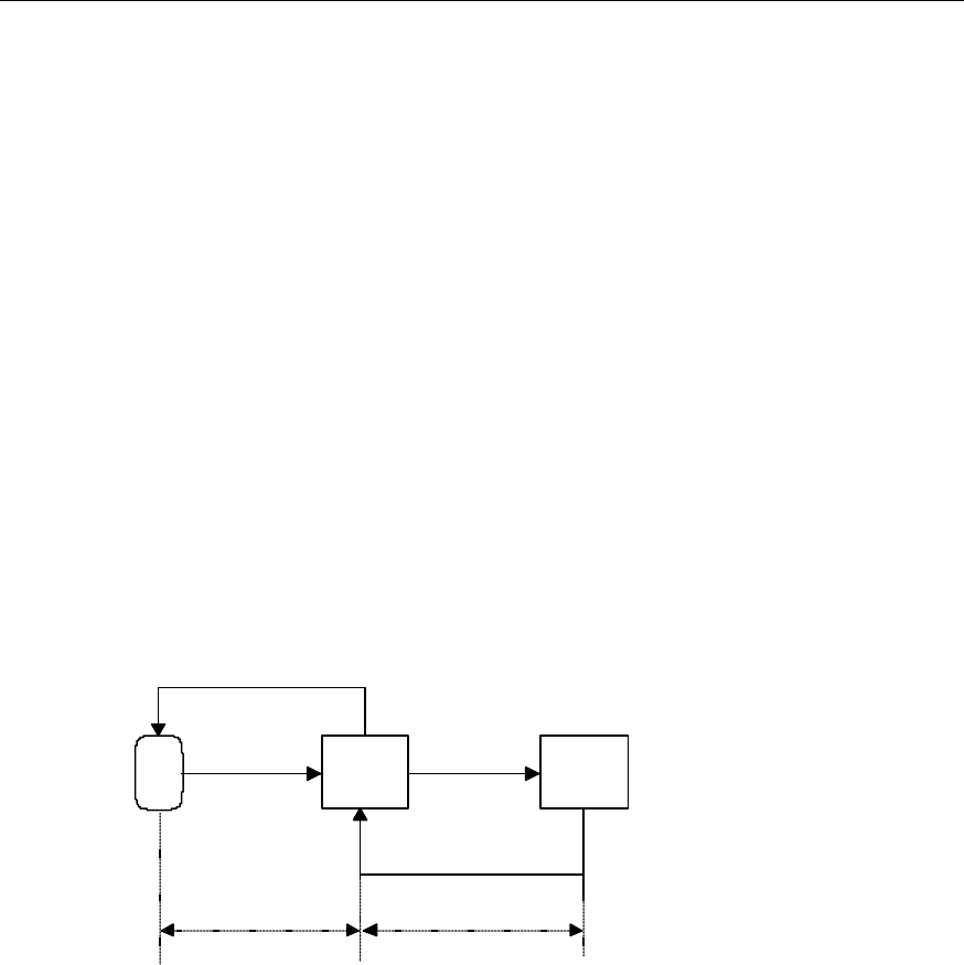
Figure 4-1 illustrates the principle of closed-loop power control.
MS BTS BSC
Eb/Nt FER
Power Control Bit
Eb/Nt changing
quantity
Inner loop Outer loop
Figure 4-1 Close-loop power control
In the inner-loop power control, the BTS issues the power control bit according to the
received Eb/Nt value.
In the outer-loop power control, the BSC adjusts the Eb/Nt value according to the
Frame Error Rate (FER) of the received reverse signal. Then the BTS uses the newly
set Eb/Nt value to issue the power control bit. In this way, the transmit power of the MS
can be controlled.
III. Rate control (only applied to 1xEV-DO forward link)
1) Forward link
The AT controls the rate of the forward traffic channel through Data Rate Control
(DRC) channel assignment.
2) Reverse link

Technical Manual
Airbridge BTS3606A CDMA Base Station System Description
Chapter 4 Main Functions
4-3
The system transmits at the maximum allowed rate through the Control Channel
(CC).
The AT first transmits at 9.6 kbps, and then increases the rate gradually according
to the Reverse Activity Bit (RAB) sent by the AN.
l If the RAB sent by all sectors in the Active Set is 0 and when a certain
condition is met, the AT multiples the rate every other 26.67 ms until the rate
reaches the maximum allowed rate.
l If the RAB sent by at least one sector in the Active Set is 1, the AT decreases
the rate by half when a certain condition is met.
4.2 Handoff
When the MS/AT moves out of the current serving cell/sector or the conversation
quality deteriorates to an unacceptable degree, the MS will be handed off to another
cell/sector to maintain the ongoing conversation.
If the handoff of MS/AT to another cell/sector helps to improve the conversation quality
and network performance, it is also possible to trigger the handoff procedure.
Different from the CDMA2000 1x, the 1xEV-DO introduces virtual soft handoff function
to the forward link.
I. Soft handoff
The soft handoff happens between neighboring cells which serve on the same
frequency and belong to different BTSs. The two different BTSs can belong to the same
BSC, or two different BSCs connected with A3/A7 interface.
In the soft handoff procedure, the MS maintains the connection with the previous cell till
it establishes the communication with the new cell. The MS can establish radio links
with multiple cells, select and combine data received from these links to improve the
conversation quality and reduce call drops.
II. Softer handoff
The softer handoff happens between neighboring sectors that serve on the same
frequency and belong to the same BTS. It is a special case of soft handoff.
Since the MS establishes radio links with multiple sectors under the same BTS, the
BTS can combine the diversity signals received by its sectors from the MS.
Therefore, the conversation quality during softer handoff is better than that of soft
handoff.
III. Virtual soft handoff (only applied to the 1xEV-DO forward link)
The AT monitors all pilot signals in the Active Set and selects the best as its serving
sector. Then, it receives signaling messages and data from the selected sector. This
process is called virtual software handoff.

Technical Manual
Airbridge BTS3606A CDMA Base Station System Description
Chapter 4 Main Functions
4-4
A cell knows whether it is selected according to the DRC Cover.
IV. Hard handoff
In the hard handoff procedure, the MS firstly interrupts the connection with the previous
cell, and then sets up the connection with the new cell. Therefore, call drop may occur.
Hard handoff includes:
l Intra-frequency hard handoff: Handoff between the BSCs without A3/A7 interface
in-between.
l Inter-frequency hard handoff: Handoff between cells serving on different
frequencies.
4.3 Radio Configuration
The Um interface of the BTS3606A supports CDMA2000 1x. It is compatible with
1xEV-DO. The spreading rate is 1.2288 Mcps.
The CDMA2000 1x physical layer supports multiple Radio Configurations (RCs).
Different radio configurations support the frames of the different rate sets, and have
different channel configurations and spreading spectrum structures.
The transmission combinations supported by the BTS3606A include:
l Forward RC1 and reverse RC1
l Forward RC2 and reverse RC2
l Forward RC3 or RC4, and reverse RC3
l Forward RC5 and reverse RC4
Each RC supports traffic channel at different data rates. The performance of the
CDMA2000 1x system varies with RCs. For example, the CDMA2000 1x system with
RC1 and RC2 is compatible with IS-95A/B.
4.4 Channel Configuration
A series of physical channels have been defined on the Um interface. These physical
channels are classified by the channel features. To support higher-rate data
transmission, the 1xEV-DO uses a channel design different from that of the CDMA2000
1x.
4.4.1 CDMA2000 1x Channel
The following shows the classification of the CDMA2000 1x channel.
I. Forward channel
The CDMA2000 1x forward channel includes Forward Common Channel and Forward
Dedicated Channel.
The Forward Common Channel is further divided into:

Technical Manual
Airbridge BTS3606A CDMA Base Station System Description
Chapter 4 Main Functions
4-5
l Forward Pilot Channel (F-PICH)
It provides synchronization signals to the MSs operating in the BTS coverage.
Different from other channels, the F-PICH is an unmodulated spread spectrum
signal that is always in the transmitting status.
l Forward Sync Channel (F-SYNCH)
It provides the initial time synchronization information to MSs operating in the BTS
coverage.
l Forward Paging Channel (F-PCH)
It sends the system information and MS-specific message to the MSs operating in
the BTS coverage. Each CDMA channel in a sector can support seven paging
channels at most.
l Forward Quick Paging Channel (F-QPCH)
The BTS uses this channel to send the paging order and system configuration
change order to slotted-mode MSs, instructing them to receive the paging
messages. As a result, the MS battery energy is saved.
l Forward Common Control Channel (CCCH)
The BTS uses this channel to send system message and message to dedicated
MS.
The Forward Dedicated Channel is further divided into:
l Forward Dedicated Control Channel (F-DCCH)
It carries traffic information and signaling information between the MS and the
BTS.
l Forward Fundamental Channel (F-FCH)
It carries traffic information between the MS and the BTS.
l Forward Supplemental Channel (F-SCH)
It carries traffic information between the MS and the BTS. It is only applicable to
RC3, RC4 and RC5.
II. Reverse channel
The CDMA2000 1x forward channel includes Reverse Common Channel and Reverse
Dedicated Channel.
The Reverse Common Channel is further divided into:
l Reverse Access Channel (R-ACH)
The MS uses this channel to communicate with the BTS and respond to paging
channel message.

Technical Manual
Airbridge BTS3606A CDMA Base Station System Description
Chapter 4 Main Functions
4-6
The MS uses random access protocol to initiate access procedure. Regarding
each supported paging channel, thirty-two access channels can be supported at
most.
l Reverse Enhanced Access Channel (R-EACH)
The MS uses this channel to initiate the communication with the BTS or respond to
dedicated paging channel message.
The Reverse Dedicated Channel is further divided into:
l Reverse Fundamental Channel (R-FCH)
It carries the traffic information between the MS and the BTS.
l Reverse Dedicated Control Channel (R-DCCH)
It carries traffic information and signaling information between the MS and the
BTS.
l Reverse Supplemental Channel (R-SCH)
It carries the traffic information between the MS and the BTS. It is applicable to
RC3 and RC4 only.
4.4.2 CDMA2000 1xEV-DO Channel
The following shows the classification of the CDMA2000 1xEV-DO channel.
I. Forward channel
The forward channel of the 1xEV-DO adopts Time Division Multiplex (TDM) mode.
It includes four types of channels: Pilot Channel, Media Access Control (MAC) Channel,
Control Channel, and Traffic Channel.
l Pilot Channel
Different from the continuous pilot of IS-95/1x system, the Pilot Channel is only
transmitted on the activated forward channels in the 1xEV-DO system.
Pilot Channel is the unmodulated signal used for synchronization of ATs under the
coverage of the sector and other functions.
l MAC Channel
There are three code sub-channels under the MAC Channel:
--Reverse Activity (RA) sub-channel, used for the reverse overload control of the
Um interface.
--Reverse Power Control (RPC) sub-channel, used for reverse power control.
--Data Rate Control Lock (DRCLock) sub-channel, used by the AN to inform the
AT whether the DRC channel of the AT can be properly demodulated. It plays an
important role in helping the AT with the forward virtual handoff.
l Control Channel

Technical Manual
Airbridge BTS3606A CDMA Base Station System Description
Chapter 4 Main Functions
4-7
The Control Channel is similar to the paging channel in the CDMA2000 1x system.
It broadcasts various overhead messages and transmits other uni-cast messages
such as paging message.
l Traffic Channel
The Traffic Channel transmits traffic data. It is multiplexed by multiple users at
different time.
II. Reverse channel
The reverse channel of the 1xEV-DO includes reverse access channel and reverse
traffic channel.
l Reverse access channel
The AT uses it to originate a call or respond to network paging message. The
reverse access channel covers Pilot sub-channel (transmitted on channel I) and
Data sub-channel (transmitted on channel Q).
l Reverse traffic channel
The reverse traffic channel covers Pilot Channel, Media Access Control (MAC)
Channel, Acknowledgement (ACK) Channel, and Data Channel.
--Pilot Channel
It helps with the coherence demodulation and phase estimation of the BTS3606A.
--MAC Channel
It consists of Reverse Rate Indicator (RRI) sub-channel and DRC sub-channel.
The AT uses the DRC sub-channel to report the quality of the forward channel to
the AN. The AN can adjust the rate and the sector for transmitting data to the AT
according to the message of DRC channel. In this way, the air resource is best
utilized.
The data channel of the reverse traffic channel uses the RRI sub-channel to
determine the rate for transmitting data.
--ACK sub-channel
It helps the AT notify the AN whether the data packet of forward traffic channel is
correctly received. This function helps adjust the forward rate forecast by the AT to
improve the performance of the system.
--Data sub-channel
It is used to transmit the reverse data. In the 1xEV-DO system, the data
sub-channel can transmit data at five rates: 9.6 kbps, 19.2 kbps, 38.4 kbps, 76.8
kbps, or 153.6 kbps.

Technical Manual
Airbridge BTS3606A CDMA Base Station System Description
Chapter 4 Main Functions
4-8
4.5 Multi-carrier
The BTS3606A supports multi-carrier technology. The single-carrier cabinet can hold
both the single-carrier and multi-carrier modules.
A single-carrier transceiver module (consisting of one CTRM and one CHPA) can
process one carrier signal. A multi-carrier transceiver module (consisting of one CMTR
and one CMPA) can process three carrier signals. Hence, in a single-carrier cabinet,
the adoption of multi-carrier transceiver module can realize the maximum configuration
of S(6/6/6), that is, 18 sector carriers.
The multi-carrier module supports the 1900 MHz and 800 MHz. The BTS3606A of later
version is expected to supported more bands.
4.6 Receiving Diversity
The BTS3606A supports receiving diversity function. The receiving diversity is realized
through two sets of independent receiving equipment, each of which comprises
antenna, feeder, CDDU, and main/diversity receiving channels.
The two sets of receiving equipment demodulate the received signals simultaneously.
Then the baseband processing unit decodes the signals with diversity combining
algorithm so as to provide some diversity gain.
The receiving diversity enhances the anti-attenuation capability of the BTS receiver,
and ensures the receiving effect of the BTS under complicated radio environment.
4.7 Cell Breathing
Under the control of the BSC, the BTS3606A adjusts the transmit power to control the
effective coverage area and balance the system load as required.
When the BTS3606A provides the cell breathing function, the controllable range of the
transmit power is from 0 dB to 24 dB and the adjustment step of transmit power is 0.5
dB.

Technical Manual
Airbridge BTS3606A CDMA Base Station System Description
Chapter 5 Reliability Design
5-1
Chapter 5 Reliability Design
This chapter introduces the system reliability, hardware reliability, and software
reliability design of the BTS3606A.
5.1 System Reliability
The system reliability design involves the following aspects:
I. De-rating design
The de-rating design aims to lower the electrical stress and temperature stress on the
high-power or heat-generating components to values less than the rated ones. It delays
performance degeneration and prolongs the service life of these components.
II. Selection, control, and normalization of components
The category, specifications and manufacturers of the components are carefully
selected depending on the requirements of the product reliability and maintainability.
The replaceability and normalization of components is also important in selecting
components.
All components are high-quality ones selected through aging test. Strict quality control
is implemented on hardware assembling procedures to ensure high reliability and
stability in the long run.
III. Thermal design
The thermal design focuses on following items to minimize the impact of temperature
changes upon product performance:
l Component selection
l Circuit design
l Mechanical design
l Heat dissipation design
The thermal design of the BTS3606A ensures that it can work reliably in a wide range
of temperatures.
IV. EMC design
The EMC design ensures that the ElectroMagnetic Interference (EMI) from other
equipment in the same electromagnetic environment does not degrade the
performance of the BTS3606A to an unacceptable level. At the same time, the EMI
generated by the BTS3606A does not degrade the performance of other equipment in
the same electromagnetic environment to an unacceptable level.

Technical Manual
Airbridge BTS3606A CDMA Base Station System Description
Chapter 5 Reliability Design
5-2
V. Redundancy design
For the purpose of reliability, the system is designed with several sets of units
performing the same function. The system will not fail unless the number of units failed
amounts to the specified quantity.
VI. Reliability design for input voltage
l The system is protected against reverse connection of power supply.
l The input voltage is tested and alarm signal will be generated when the voltage is
too low or too high.
l The system is protected against sharp voltage drop and lightning strikes.
l The system can protect program and data in the case of power failure.
VII. Maintainability design
The reasonable internal wiring of the BTS facilitates board replacement. To replace a
faulty board, user only needs to remove the cable of this board. The board can be
removed and inserted directly from the front of the cabinet.
In addition, board indicators are provided to help users identify board status.
VIII. Fault monitoring and handling
The BTS3606A system can self-detect and diagnose the faults of software and
hardware. It can record, output and print various fault information. In addition, it collects
environment condition information and generates alarms if there is any problem.
When faults occur to the hardware, the system locates the fault, isolates the faulty
component, and automatically carries out switchover to the standby components that
operate normally.
The system makes a final confirmation on a hardware fault through repeated detection,
thus avoiding the reconfiguration of the system or the degradation of QoS due to
contingent faults.
When faults occur to the software, automatic error-correction and recovery functions
will be executed, including restarting and reloading.
The network management system records, outputs, and notifies the users of critical
faults. In this way, users can operate and maintain the system with ease through
maintenance console.
5.2 Hardware Reliability
The hardware reliability design involves the following aspects:

Technical Manual
Airbridge BTS3606A CDMA Base Station System Description
Chapter 5 Reliability Design
5-3
I. Protection against wrong insertion of boards
When a board is inserted into a wrong slot, the special guide pins will prevent the board
from touching the backplane. This avoids the possible damage to the equipment owing
to wrong insertion.
II. Active-standby switchover of BCKM
The active BCKM can back up the files to the standby BCKM periodically.
Once critical faults occur to the active BCKM, the original standby BCKM will function
as the active BCKM to ensure normal operation of the BTS.
III. BCIM backup slots
The BTS3606A has BCIM backup slots. Normally the BCIMs reside in the upper slots.
When the upper slots are faulty, the lower slots are used instead.
IV. BCIM/BCKM power supply backup
The power modules of the BCIM and BCKM are mutually backed up. When the power
module of one board is faulty, the power module of another board is used instead.
V. N+1 backup for baseband fans
The baseband fans work in the N+1 backup mode. One standby fan is equipped. When
one fan is faulty, this standby fan starts working to ensure the performance of the
baseband ventilation system.
VI. Link backup of Abis interface
The BTS3606A supports the Abis interface link backup function to improve the
reliability of links. When the backup link is configured, if the active link is faulty, the
system can automatically carry out the active-standby link switchover.
VII. CE pool design of the CCPM
The CCPM adopts the CE pool design. The CCPMs are connected into a daisy chain,
which increases the utilization rate of the channel resource and enables flexible
configuration of the channel capacity of each sector carrier. This enhances the
reliability of the system.
VIII. Status monitoring and alarm report
The BCKM can monitor the status of other boards or modules, and report alarms to
ensure timely fault location.
IX. Distributed power supply
The system adopts distributed power supply. The DC/DC power supply module works
in the N+1 redundancy mode.

Technical Manual
Airbridge BTS3606A CDMA Base Station System Description
Chapter 5 Reliability Design
5-4
When an error occurs to a module, an alarm is generated and sent to the BAM. The
system also supports online insertion and removal of boards.
5.3 Software Reliability
The software reliability design involves the following aspects:
I. Periodic check of key resources
This function aims to check the software resource which has been occupied for a long
time. If certain resource becomes unavailable owing to software error, the check
mechanism will release that resource and output logs and alarms.
II. Process monitoring
Process monitoring provides channel for outputting various software and hardware
faults while the software is running. It can monitor the running status of a specific task
or system, and report the information to the outside.
III. Data check
Data check consists of the following contents:
l Check the data consistency of different processing boards, restore the data, and
output logs and alarms.
l Check the consistency of the data input by the user to ensure correct reference
relation among data.
l Use the rollback function to restore the data to the initial state when the
modification of some data fails at a certain point.
IV. Fault isolation
In the BTS3606A, when a fault occurs to one software module, other software modules
can run normally.
The software also has the fault tolerance and correction functions. The minor operation
exceptions will not cause the reset or reboot of the system.
V. Reversible upgrade
The system provides such function as program and data restoration. When the
upgrade fails, the function helps restore to the original program and data configuration.
VI. Log function
The operation and maintenance software can automatically record user's operations
and save them into a log file.
When an unknown error occurs to the system, log files can help to find out the status in
the normal condition for fault location or data restoration.
Technical Manual
Airbridge BTS3606A CDMA Base Station System Description
Chapter 6 Operation and Maintenance System
6-1
Chapter 6 Operation and Maintenance System
The operation and maintenance system covers the local operation and maintenance
system, and the M2000 Mobile Integrated Network Management System (hereafter
briefed as M2000 system).
This chapter introduces how to perform the local and remote maintenance through the
local operation and maintenance system.
This chapter also briefs the basic structure and functions of the M2000 system. The
details information of the M2000 system is available in the related manuals of M2000.
6.1 Structure of the Operation and Maintenance System
6.1.1 Local Operation and Maintenance System
Figure 6-1 shows the structure of the BSS/AN local operation and maintenance
system.
PSTN
Internet
IPoE
IPoA
IPoA
Router
Modem
IPoE
IPoE
IPoE
Router
Modem
IPoE
BSC
BTS
BTS
IPOA : IP over ATM IPOE: IP over Ethernet
Figure 6-1 BSS/AN local operation and maintenance system
I. Far-end maintenance
The Local Maintenance Terminal (LMT) connects to the BSC BAM to realize the far-end
maintenance on BTS.
The local operation and maintenance system of the BSS is designed in Client/Server
(C/S) structure, where LMT is a Client and BAM a Server. The operation procedure is
as follows:
1) The user inputs operation commands through the LMT.
2) The BAM processes commands from LMTs.

Technical Manual
Airbridge BTS3606A CDMA Base Station System Description
Chapter 6 Operation and Maintenance System
6-2
3) After processing, the BAM sends these commands to the host (BSC or BTS) and
then waits for the response.
4) The BAM records the operation results (such as success, failure, timeout, or
abnormality) and sends the results to the LMT in a specified format.
Users can also use the BAM to manage the BTSs under its control and carry out
network planning in a centralized way.
II. Remote maintenance
The LMT visits the BTS by dialing up on the Modem to realize the remote maintenance.
When maintenance engineers cannot perform far-end maintenance owing to some
cause (for example, the IPOA maintenance channel is faulty), they can use the remote
maintenance method to maintain the BTS.
III. Near-end maintenance
In the BTS equipment room, the LMT connects to the BTS through network cables to
realize the near-end maintenance.
Users can log in to the BTS through Telnet Client and execute the MML command to
maintain the BTS.
User can also employ the reverse maintenance function to log in to the BAM from the
BTS to realize the maintenance of the whole BSS.
6.1.2 Mobile Integrated Network Management System
The M2000 system implements the centralized maintenance function. In this system,
the M2000 server is the core. Various mobile network elements (such as BSC, MSC,
and HLR) connect to the M2000 system through Local Area Network (LAN) or Wide
Area Network (WAN).
The BSC connects to the M2000 system through the BAM.
Figure 6-2 shows the typical networking of the M2000 mobile integrated network
management system.
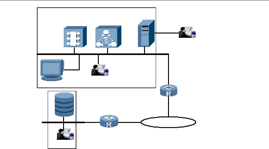
Technical Manual
Airbridge BTS3606A CDMA Base Station System Description
Chapter 6 Operation and Maintenance System
6-3
M2000 Server WS
Dialup Server
NE
PSTN
E1,DDN,X.25,frame relay
NE
NE
WS
Figure 6-2 Networking of M2000 mobile integrated network management system
The M2000 system completes the configuration management, performance
management, and fault management.
l Configuration management. Collect, store, query, and modify the data of NE
equipment in the network.
l Performance management. Users can register the traffic measurement tasks of
the NEs on the Client, and view the execution results of the traffic measurement
tasks registered on the whole network.
l Fault management. Users can set combined conditions to get the required alarm
data of the NEs from the Alarm Client, view the results, and perform related
operations
6.2 Operation and Maintenance Function
The BTS3606A provides powerful operation and maintenance functions.
I. Security management
To prevent illegal operation, the system provides powerful security management
function to manage and control user's operation and operating equipment.
The user needs to log in for authentication before operating the BTS3606A.The system
provides multi-level authority mechanism so that only the authorized user can use
specified command sets.
The timeout locking function is provided. When the user does not operate the system
for a specific period of time, the system will automatically lock the screen. User needs
to enter the right password to go on with the operation.

Technical Manual
Airbridge BTS3606A CDMA Base Station System Description
Chapter 6 Operation and Maintenance System
6-4
Before the execution of important commands, the system will show the possible
execution results and prompt the user for confirmation.
II. Alarm management
The system performs centralized management over the alarms of the BSC and the
BTS. The BSS Maintenance Console provides real-time alarm management function:
l Collect alarms
l Clear alarms
l Query alarms
l Handle alarms
l Save alarms
l Interpret alarms
l Prompt alarms
l Shield alarms
l Filter alarms
l Acknowledge alarms
l Analyze alarms
In addition, the alarm management system provides online help and hierarchical
filtering to help locate faults and provide alarm recovery method.
While reporting alarms, the BTS3606A drives status indicators and alarm box to
provide audible and visual alarms.
III. Loading management
The loading management allows the loading of the software and the configuration data.
Software loading involves the downloading and activation of the Central Processing
Unit (CPU) software and the Field Programmable Gate Array (FPGA) logic.
Configuration data loading includes both the downloading and uploading of
configuration data.
IV. Configuration management
The configuration management is to configure BTS equipment and radio resources. It
also enables the user to query the configuration data and check data consistency.
Both online and offline configuration functions are provided with batch processing
function for data configuration.
V. Equipment management
The equipment management is to monitor and query the status of the board and the
system, so that users can learn the running status of the system timely. It also provides
users with operation log and system running log to facilitate fault location and clearing.
The equipment management function includes:

Technical Manual
Airbridge BTS3606A CDMA Base Station System Description
Chapter 6 Operation and Maintenance System
6-5
l Version query
l Status query
l Electronic label query
l Log management
l Equipment reset
l Resource blocking/unblocking
l Power supply management
VI. Test management
The test management facilitates fault location and the optimization of system
performance. The tests include board loopback test, self-detection test, and Abis link
test.
VII. Tracing management
The tracing management aims to help the fault location and performance measurement
analysis. The traced objects include various interfaces and indices.
Some indices (such as CPU load, board temperature, BTRM transmit power, and
receive signal strength indicator) can be displayed in graphics on real-time basis.

Technical Manual
Airbridge BTS3606A CDMA Base Station System Description
Chapter 7 Technical Specifications
7-1
Chapter 7 Technical Specifications
This chapter provides the engineering specifications, protection specification, capacity
specifications, and performance specifications of the BTS3606A.
7.1 Structure and Environment Specifications
The structure and environment specifications include cabinet dimensions, weight,
power, ambient temperature, and relative humidity.

Technical Manual
Airbridge BTS3606A CDMA Base Station System Description
Chapter 7 Technical Specifications
7-2
Cabinet dimensions 1700 mm x 1200 mm x 1000 mm (Height×Width×Depth)
220/230/240V AC:
Single-phase/three-phase input
Voltage range: 176 V to 264 V
Frequency range: 47 Hz to 63 Hz
Over-voltage protection when the voltage reaches 290V.
Power supply 110/115/127V AC:
Single-phase/three-phase input
Voltage range: 90 V to 135 V
Frequency range: 47 Hz to 63 Hz
Under-voltage protection when the voltage reaches 85V.
Cabinet weight 650 kg (excluding the batteries and the built-in transmission
equipment)
Air
conditioner
6100 W (with air conditioner set to cooling function, and without battery
cabinet)
11000 W (with air conditioner set to cooling function, and with battery
cabinet)
6000 W (with air conditioner set to heating function, and without battery
recharging considered)
Power
consumption
(in full
configuration)
Heat
exchanger
4500W (without battery cabinet)
9500W (with battery cabinet)
6000W (heating, without recharging)
Air
conditioner
-40°C to 55°C
Operating
ambient
temperature Heat
exchanger -40°C to 45°C
Relative humidity 5% to 100%
Noise ≤ 65 dBA (The noise varies with the ambient temperature)
Availability ≥ 99.999%
MTBF:≥ 100000 hours
Reliability
MTTR: ≤ 1 hour (excluding the time spent on the journey)
MTTR: ≤3 hours (including the time spent on the journey)
7.2 Capacity Specifications
The maximum capacity of one BTS3606A is six sector carriers. With the multi-carrier
modules, the capacity can reach 18 sector carriers.

Technical Manual
Airbridge BTS3606A CDMA Base Station System Description
Chapter 7 Technical Specifications
7-3
The BTS3606A supports two types of channel processing boards: CCPM and CECM.
The CCPM supports the CDMA2000 1x protocols, whereas the CECM supports the
CDMA2000 1xEV-DO protocols.
I. CDMA2000 1x capacity
The BTS capacity is given according to the number of sector carriers configured. One
sector carrier can serve about 20 IS95 subscribers or about 40 CDMA2000 1x
subscribers.
The maximum reverse channel capacity of one carrier (three sectors) is 128 channels.
II. CDMA2000 1xEV-DO capacity
The BTS capacity is given according to the number of sector carriers configured. One
sector carrier can serve up to 48 subscribers.
The maximum reverse channel capacity of one carrier (three sectors) is 96 channels.
7.3 Transmitter and Receiver Specifications
This section provides the specifications of the BTS3606A transmitter and receiver at
different bands.
7.3.1 Transmitter and Receiver Specifications at 450 MHz Band
This following lists the BTS3606A transmitter and receiver specifications when the
BTS3606A works at the 450 MHz band.
I. Transmitter specifications
Working band 460 MHz to 467 MHz
Channel bandwidth 1.23 MHz
Channel precision 25 kHz, 20 kHz
Frequency tolerance Ÿ ! 0.05 ppm
Transmit power 25 W (the maximum value measured at the feeder port on the top of the
cabinet)
II. Receiver specifications
Working band 450 MHz to 457 MHz
Channel bandwidth 1.23 MHz
Channel precision 25 kHz, 20 kHz
Sensitivity of signal receiver Better than -127 dBm (RC3, main and diversity receiving)

Technical Manual
Airbridge BTS3606A CDMA Base Station System Description
Chapter 7 Technical Specifications
7-4
7.3.2 Transmitter and Receiver Specifications at 800 MHz Band
This following lists the BTS3606A transmitter and receiver specifications when the
BTS3606A works at the 800 MHz band.
I. Transmitter specifications
Working band 869 MHz to 894 MHz
Channel bandwidth 1.23 MHz
Channel precision 30 kHz
Frequency tolerance Ÿ ! 0.05 ppm
Transmit power
Single-carrier: 25 W (the maximum value measured at the feeder port on the
top of the cabinet)
Multi-carrier: 50 W (measured on the top of the cabinet)
II. Receiver specifications
Working band 824 MHz to 849 MHz
Channel bandwidth 1.23 MHz
Channel precision 30 kHz
Sensitivity of signal
receiver Single-carrier: Better than -127 dBm (RC3, main and diversity receiving)
Multi-carrier: Better than -126 dBm (RC3, main and diversity receiving)
7.3.3 Transmitter and Receiver Specifications at 1900 MHz Band
This following lists the BTS3606A transmitter and receiver specifications when the
BTS3606A works at the 1900 MHz band.
I. Transmitter specifications
Working band 1930 MHz to 1990 MHz
Channel bandwidth 1.23 MHz
Channel precision 50 kHz
Frequency tolerance Ÿ ! 0.05 ppm
Transmit power
Single-carrier: 25 W (the maximum value measured at the feeder port on the
top of the cabinet)
Multi-carrier: 40 W (measured on the top of the cabinet)

Technical Manual
Airbridge BTS3606A CDMA Base Station System Description
Chapter 7 Technical Specifications
7-5
II. Receiver specifications
Working band 1850 MHz to 1910 MHz
Channel bandwidth 1.23 MHz
Channel precision 50 kHz
Sensitivity of signal
receiver Single-carrier: Better than -127 dBm (RC3, main and diversity receiving)
Multi-carrier: Better than -126 dBm (RC3, main and diversity receiving)
7.4 Specifications for ODU3601C Cascading
The following lists the related specifications when the BTS3606A connects to the
ODU3601C.
Maximum distance of single cascading 10 km, 70 km (corresponding to two
types of CCPM)
Maximum number of cascading levels 3
CDMA2000 1x
Maximum total distance after cascading 90 km
Maximum distance of single cascading 10 km
Maximum number of cascading levels 3 1xEV-DO
Maximum total distance after cascading 10 km

Technical Manual
Airbridge BTS3606A CDMA Base Station System Description
Chapter 8 Technical Standards
8-1
Chapter 8 Technical Standards
8.1 General Technical Specifications
The BTS3606A is compliance with the following general technical specifications:
l TIA/EIA-97-D: Recommended Minimum Performance Standards for Base
Stations Supporting Dual-mode Spread Spectrum Mobile Stations.
l Federal IMT-MC (CDMA 2000) Cellular Mobile System Operating in Band 450
MHZ.
l C.S0032-0V1.0 Recommended Minimum Performance Standards for CDMA2000
High Rate Packet Data Access Network
l C.S0039-0V1.0 Enhanced Subscriber Privacy for CDMA2000 High Rate Packet
Data
l C.S0038-0V1.0 Signaling Conformance Specification for High Rate Packet Data
Air Interface
8.2 Um Interface
The BTS3606A is compliance with the following Um interface specifications:
I. Physical layer
TIA/EIA IS-2000-2-A: Physical Layer Standard for CDMA 1X Standards for Spread
Spectrum Systems.
C.S0024-0V4.0 CDMA2000 High Rate Packet Data Air Interface Specifications
II. MAC layer
TIA/EIA IS-2000-3-A: Medium Access Control (MAC) Standard for CDMA 1X
Standards for Spread Spectrum Systems.
III. Service capability
TSB2000: Capabilities Requirements Mapping for CDMA 1X Standards.
8.3 Abis Interface
The BTS3606A is compliance with the following Abis interface specifications:
I. Physical layer
l E1 interface:
E1 Physical Interface Specification, September 1996
l SDH STM-1

Technical Manual
Airbridge BTS3606A CDMA Base Station System Description
Chapter 8 Technical Standards
8-2
ANSI T1.101: Synchronization Interface Standard.
ITU-T G.707: (3/96) Network node interface for the synchronous digital hierarchy
(SDH).
ITU-T G.703: (10/98) Physical/electrical characteristics of hierarchical digital
interfaces.
ITU-T G.957: Optical interface for equipment and systems relating to the
synchronous digital hierarchy.
ITU-T G.958: Digital line systems based on the synchronous digital hierarchy for
use on optical fiber cables.
l ATM
AF-PHY-0086.001: Inverse Multiplexing for ATM (IMA) Specification Version 1.1.
ATM Forum af-phy-0064.000.
STR-PHY-FN64-01.00: ATM on Fractional E1/T1.
II. ATM layer
ANSI T1.627-1993: Telecommunications broadband ISDN-ATM Layer Functionality
and specification.
III. ATM adaptation layer
ITU-T recommendation I.366.2: B-ISDN ATM Adaptation Layer Type 2 Specification.
ITU-T I.363.5: B-ISDN ATM Adaptation Layer 5 Specification: Type 5 AAL.
IV. TCP/IP
RFC791: Internet Protocol.
RFC793: Transport Control Protocol.
V. Abis interface high layer protocol
3GPP2 A.R0003: Abis interface technical report for CDMA 1X Spread Spectrum
System.
VI. Self-defined standard: CDMA 1X Abis interface high layer protocol
8.4 Lightning Protection
The BTS3606A is compliance with the following lightning protection standards:
l IEC 61312-1 (1995) Protection against Lightning Electromagnetic Impulse Part I:
General Principles.
l IEC 61643-1 (1998) Surge Protective devices connected to low-voltage power
distribution systems.
l ITU -T K.11 (1993) Principles of Protection against Overvoltage and Overcurrent.

Technical Manual
Airbridge BTS3606A CDMA Base Station System Description
Chapter 8 Technical Standards
8-3
l ITU -T K.27 (1996) Bonding Configurations and Earthing Inside a
Telecommunication Building.
l ETS 300 253(1995) Equipment Engineering; Earthing and bonding of
telecommunication equipment in telecommunication centres.
8.5 Safety
The BTS3606A is compliance with the following safety requirements:
l GB4943-2000: Safety of information technology equipment.
l IEC60950 Safety of information technology equipment including Electrical
Business Equipment.
l IEC60215 Safety requirement for radio transmitting equipment.
l CAN/CSA-C22.2 No 1-M94 Audio, Video and Similar Electronic Equipment.
l CAN/CSA-C22.2 No 950-95 Safety of Information Technology Equipment
Including Electrical Business Equipment.
l UL 1419 Standard for Professional Video and Audio Equipment
l 73/23/EEC Low Voltage Directive.
l UL 1950 Safety of information technology equipment Including Electrical Business
Equipment.
l IEC60529 Classification of degrees of protection provided by enclosure (IP Code).
l GOST 30631-99. General Requirements to machines, instruments and other
industrial articles on stability to external mechanical impacts while operating.
l GOST R 50829-95. Safety of radio stations, radio electronic equipment using
transceivers and their components. The general requirements and test methods.
l GOST 12.2.007.0-75. Electrotechnical devices. The general safety requirements.
8.6 EMC
The BTS3606A is compliance with the following EMC standards:
l TS 25.105; 3rd Generation Partnership Project; TSG RAN WG4; UTRA (BS) TDD:
Radio transmission and reception89/336/EEC EMC directive Council directive of 3
May 1989 on approximation of laws of the Member States relating to
electromagnetic compatibility.
l CISPR 22 (1997): Limits and methods of measurement of radio disturbance
characteristics of information technology equipment.
l IEC 61000-6-1: 1997: Electromagnetic compatibility (EMC) - Part 6: Generic
standards - Section 1: Immunity for residential, commercial and light-industrial
environments.
l IEC 61000-6-3: 1996: Electromagnetic compatibility (EMC) - Part 6: Generic
standards - Section 3: mission standard for residential, commercial and light
industrial environments.
l IEC 61000-3-2 (1995): Electromagnetic compatibility (EMC) - Part 3: Limits -
Section 2: Limits for harmonic current emissions (equipment input current = 16 A).

Technical Manual
Airbridge BTS3606A CDMA Base Station System Description
Chapter 8 Technical Standards
8-4
l IEC 61000-3-3 (1995): Electromagnetic compatibility (EMC) - Part 3: Limits -
Section 3: Limitation of voltage fluctuations and flicker in low-voltage supply
systems for equipment with rated current = 16 A.
l IEC 61000-4-2 (1995): Electromagnetic compatibility (EMC) - Part 4: Testing and
measurement techniques - Section 2: Electrostatic discharge immunity test.
l IEC 61000-4-3 (1995): Electromagnetic compatibility (EMC) - Part 4: Testing and
measurement techniques - Section 3: Radiated, radio-frequency electromagnetic
field immunity test.
l IEC 61000-4-4 (1995): Electromagnetic compatibility (EMC) - Part 4: Testing and
measurement techniques - Section 4: Electrical fast transient/burst immunity test.
l IEC 61000-4-5 (1995): Electromagnetic compatibility (EMC) - Part 4: Testing and
measurement techniques - Section 5: Surge immunity test.
l IEC 61000-4-6 (1996): Electromagnetic compatibility (EMC) - Part 4: Testing and
measurement techniques - Section 6: Immunity to contacted disturbances,
induced by radio frequency fields.
l IEC 61000-4-11 (1994): Electromagnetic compatibility (EMC) - Part 4: Testing and
measurement techniques - Section 11: Voltage dips, short interruptions and
voltage variations. Immunity tests.
l ITU -T Recommendation K.20: Resistibility of Telecommunication Switching
Equipment to Overvoltages and Overcurrents.
l CFR 47, FCC Part 15: Radio Frequency Device.
l TS 25.113v3.1.0: 3rd Generation Partnership Project; Technical Specification
Group Radio Access Networks; Base station EMC.
l ITU -R Rec. SM.329-7: Spurious emissions.
l GOST R 51318.22-99: Electromagnetic compatibility of technical equipment.
Man-made noise from informational equipment. Limits and test methods.
l GOST 30429-96: Electromagnetic compatibility of technical equipment.
Man-made noise from equipment and apparatus used together with service
receiver systems of civil application. Limits and test methods.
8.7 Environment
The BTS3606A is compliance with the following environment requirements:
l GB4208 Degrees of protection provided by enclosure (IP code).
l GB4798 Environmental conditions for electrician and electronic products
application.
l IEC 60529 "Degrees of protection provided by enclosure (IP code)"
l IEC 60721-3-1: Classification of environmental conditions- Part3: Classification of
groups of environmental parameters and their severities-Section 1: Storage.
l IEC 60721-3-2: Classification of environmental conditions- Part3: Classification of
groups of environmental parameters and their severities-Section 2:
Transportation.

Technical Manual
Airbridge BTS3606A CDMA Base Station System Description
Chapter 8 Technical Standards
8-5
l IEC 60721-3-3 (1994): Classification of environmental conditions - Part 3:
Classification of groups of environmental parameters and their severities - Section
3: Stationary use at weather protected locations.
l IEC 60721-3-4 (1995): Classification of environmental conditions - Part 3:
Classification of groups of environmental parameters and their severities - Section
4: Stationary use at non-weather protected locations.
l ETS 300 019-2-1: Equipment Engineering (EE); Environmental conditions and
environmental tests for telecommunications equipment; Part 2-1, Specification of
environmental tests Storage.
l ETS 300 019-2-2: Equipment Engineering (EE); Environmental conditions and
environmental tests for telecommunications equipment; Part 2-2, Specification of
environmental tests Transportation.
l ETS 300 019-2-3: Equipment Engineering (EE); Environmental conditions and
environmental tests for telecommunications equipment; Part 2-3, Specification of
environmental tests Transportation Stationary use at weather-protected locations.
l ETS 300 019-2-3: Equipment Engineering (EE); Environmental conditions and
environmental tests for telecommunications equipment; Part 2-3, Specification of
environmental tests Transportation Stationary use at non-weather-protected
locations.
l IEC 60068-2-1 (1990): Environmental testing - Part 2: Tests. Tests A: Cold.
l IEC 60068-2-2 (1974): Environmental testing - Part 2: Tests. Tests B: Dry heat.
l IEC 60068-2-6 (1995): Environmental testing - Part 2: Tests - Test Fc: Vibration
(sinusoidal).
l GOST 15150-69: Machines, instruments and other industrial articles. Applications
for different climatic regions. Categories, operating, storage and transportation
conditions in compliance with the environmental factors.
l GOST 23088-80: Electronic equipment. Requirements to packing and
transportation and test methods.

Technical Manual
Airbridge BTS3606A CDMA Base Station System Description
Chapter 9 Abbreviations and Acronyms
9-1
Chapter 9 Abbreviations and Acronyms
#
1xEV-DO Single 1.25MHz carrier Evolution - Data Optimized
1xEV-DV Single 1.25MHz carrier Evolution - Data and Voice
3GPP2 3rd Generation Partnership Project 2
A
AAA Authorization, Authentication and Accounting
AC Alternating Current
ACK Acknowledgement
AN Access Network
AT Access Terminal
ATM Asynchronous Transfer Mode
B
BAM Back Administration Module
BCIM BTS Control Interface Module
BCKM BTS Clock Module
BS Base Station
BSC Base Station Controller
BSS Base Station Subsystem
C
CC Control Channel
CCPM Compact-BTS Channel Process Module
CDMA Code Division Multiple Access
CDDU Compact-BTS Dual Duplexer Unit
CECM Compact-BTS EVDO Channel Module
CFMM Compact-BTS Fan Monitor Module
CHPA Compact-BTS High power Amplifier
CIFM Compact-BTS Intermediate Frequency Module
CN Core Network
CPBM Compact-BTS Power Backplane Module

Technical Manual
Airbridge BTS3606A CDMA Base Station System Description
Chapter 9 Abbreviations and Acronyms
9-2
CPU Center Processing Unit
CRCM Compact-BTS Radio Up-Down Convert Module
CSLM Compact-BTS Serial port Lightning proof Module
CTBM Compact-BTS Transceiver Backplane Module
CTRM Compact-BTS Transceiver Module
D
DC Direct Current
DRC Data Rate Control
E
EIA Electronics Industry Association
EIB Erasure Indicator Bit
F
F-CCCH Forward Common Control Channel
F-DCCH Forward Dedicated Control Channel
F-FCH Forward Fundamental Channel
F-PCH Forward Paging Channel
FPGA Field Programmable Gate Array
F-PICH Forward Pilot Channel
F-QPCH Forward Quick Paging Channel
F-SCH Forward Supplemental Channel
F-SYNCH Forward Sync Channel
G
GLONASS Global Navigation Satellite System
GMSC Gateway Mobile Switching Center
GPS Global Positioning System
GSM Global System for Mobile Communications
H
HA Home Agent
HLR Home Location Register
HPSK Hybrid Phase Shift Keying
I
IMA Inverse Multiplexing for ATM
IPOA Internet Protocols over ATM

Technical Manual
Airbridge BTS3606A CDMA Base Station System Description
Chapter 9 Abbreviations and Acronyms
9-3
ISDN Integrated Services Digital Network
L
LMT Local Maintenance Terminal
LNA Low Noise Amplifier
M
MAC Media Access Control
MIP Mobile Internet Protocol
MML Man-Machine Language
MS Mobile Station
MSC Mobile Switching Center
MTBF Mean Time Between Failures
MTTR Mean Time To Repair
O
ODU OutDoor Unit
OML Operation & Maintenance Link
P
PCF Packet Control Function
PDSN Packet Data Service Node
PLMN Public Land Mobile Network
PMRM Power Measurement Report Message
PP2S Pulses Per 2 Seconds
PPP Peer-to-Peer Protocol
PSK Phase Shift Keying
PSTN Public Switched Telephone Network
PSU Power Supply Unit
PSUDC DC/DC Power Supply Unit
PTT Push To Talk
Q
QAM Quadrature Amplitude Modulation
QPSK Quadrature Phase Shift Keying
R
RA Reverse Activity
RAB Reverse Activity Bit

Technical Manual
Airbridge BTS3606A CDMA Base Station System Description
Chapter 9 Abbreviations and Acronyms
9-4
R-ACH Reverse Access Channel
RC Radio Configuration
R-DCCH Reverse Dedicated Control Channel
R-EACH Reverse Enhanced Access Channel
R-FCH Reverse Fundamental Channel
RLDU Receive LNA Distribution Unit
R-P Radio-Packet
RPC Reverse Power Control
RRI Reverse Rate Indicator
R-SCH Reverse Supplemental Channel
T
TDM Time Division Multiplexing
TIA Telecommunications Industry Association
U
UNI User Network Interface