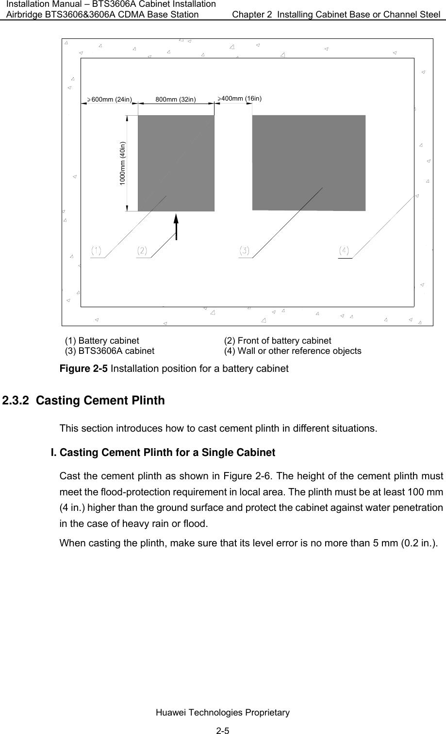
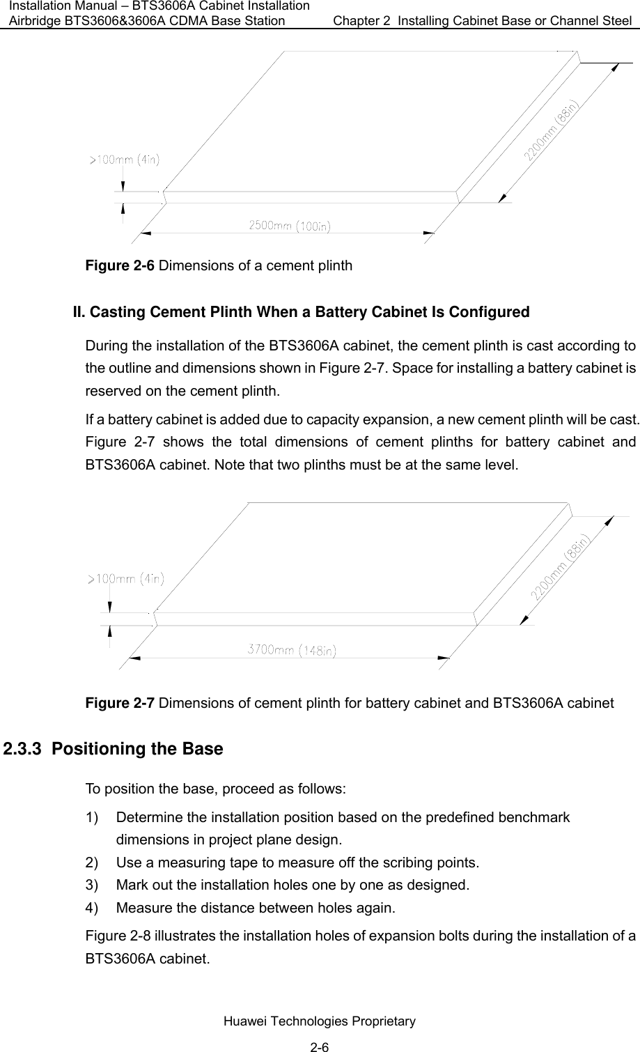
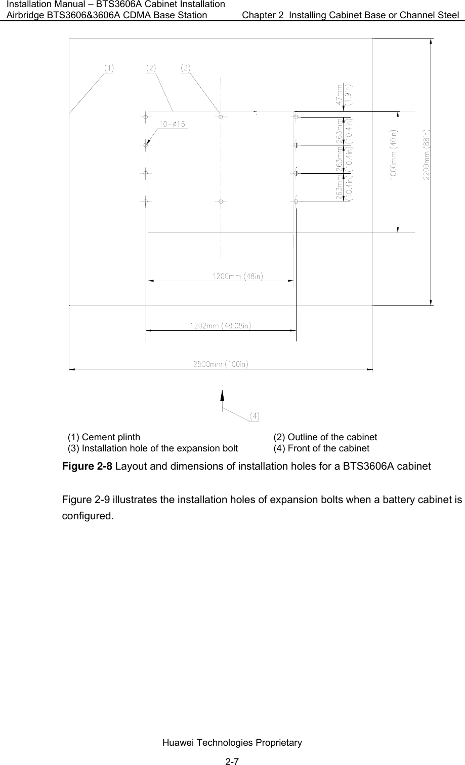
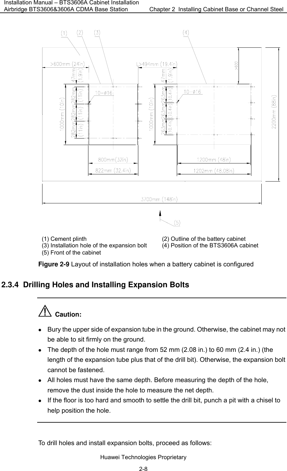
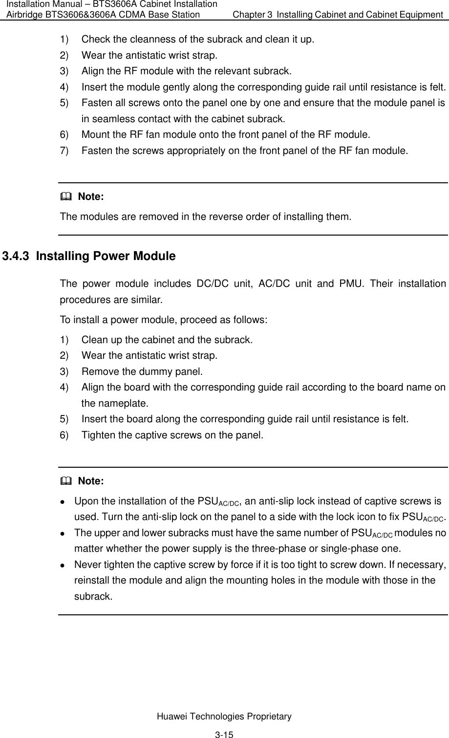
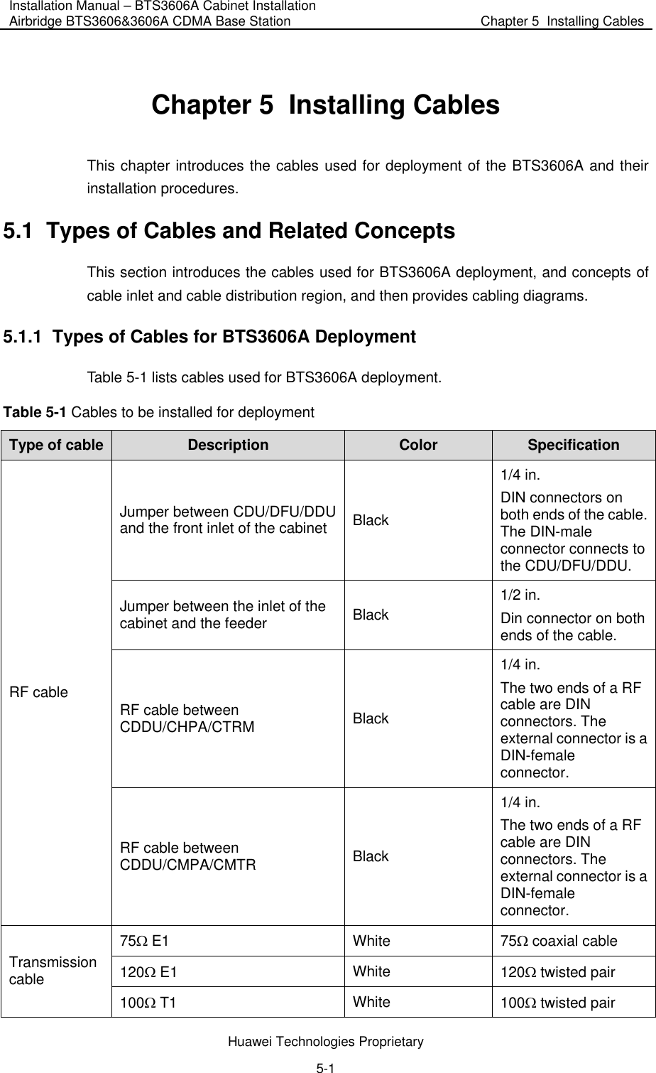
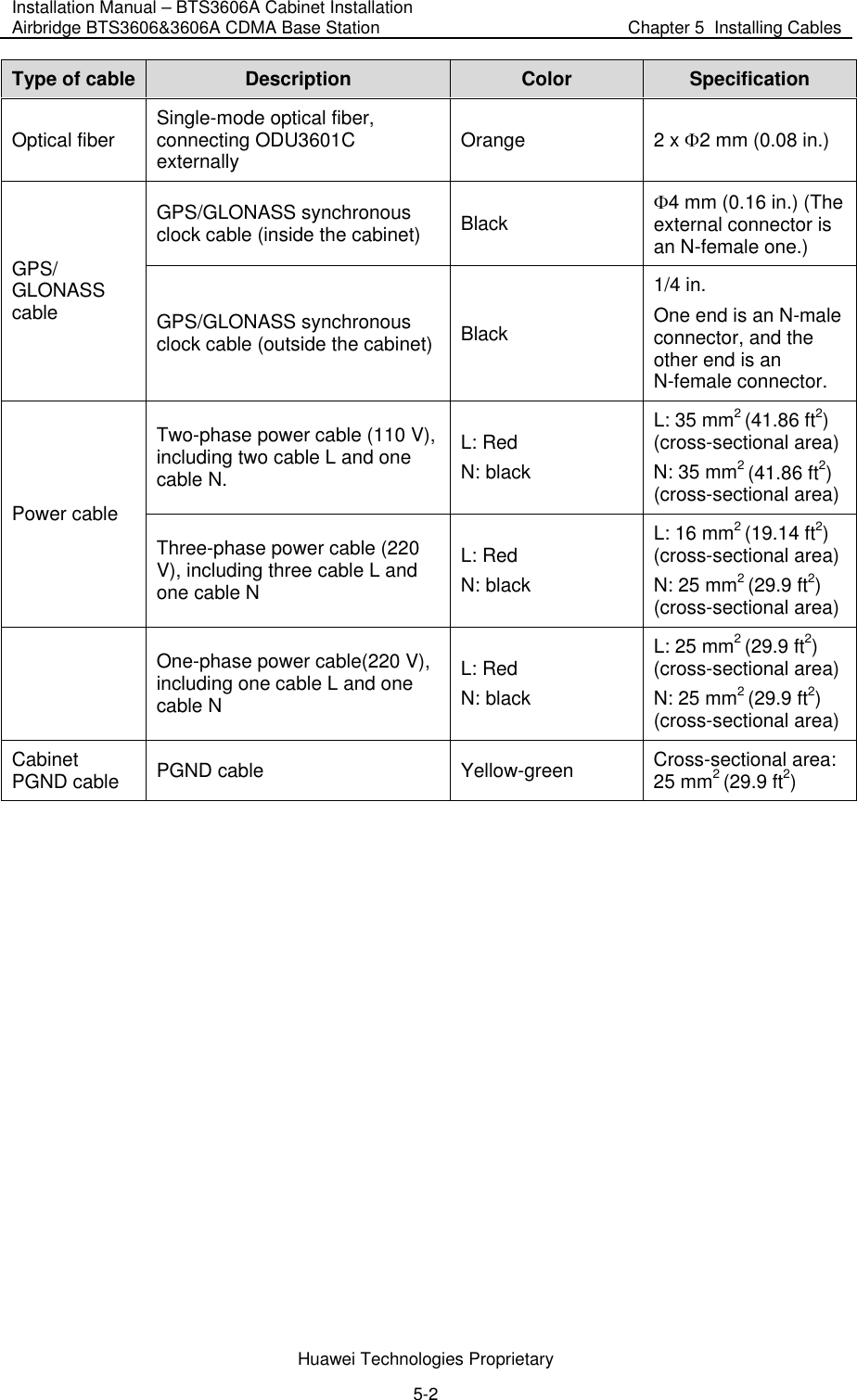
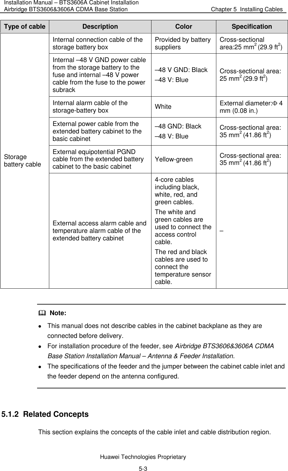
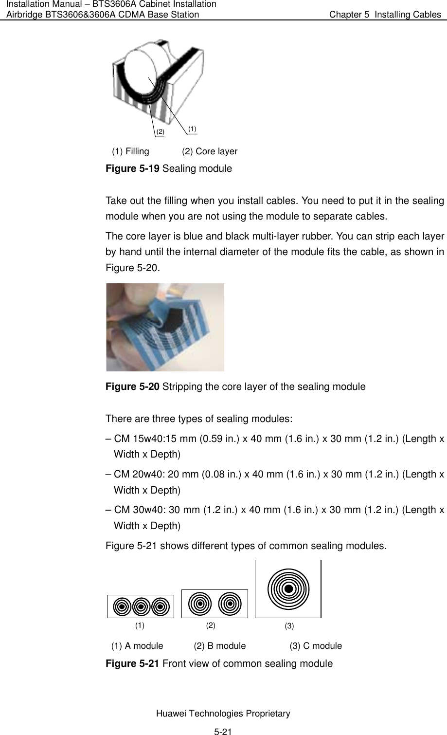
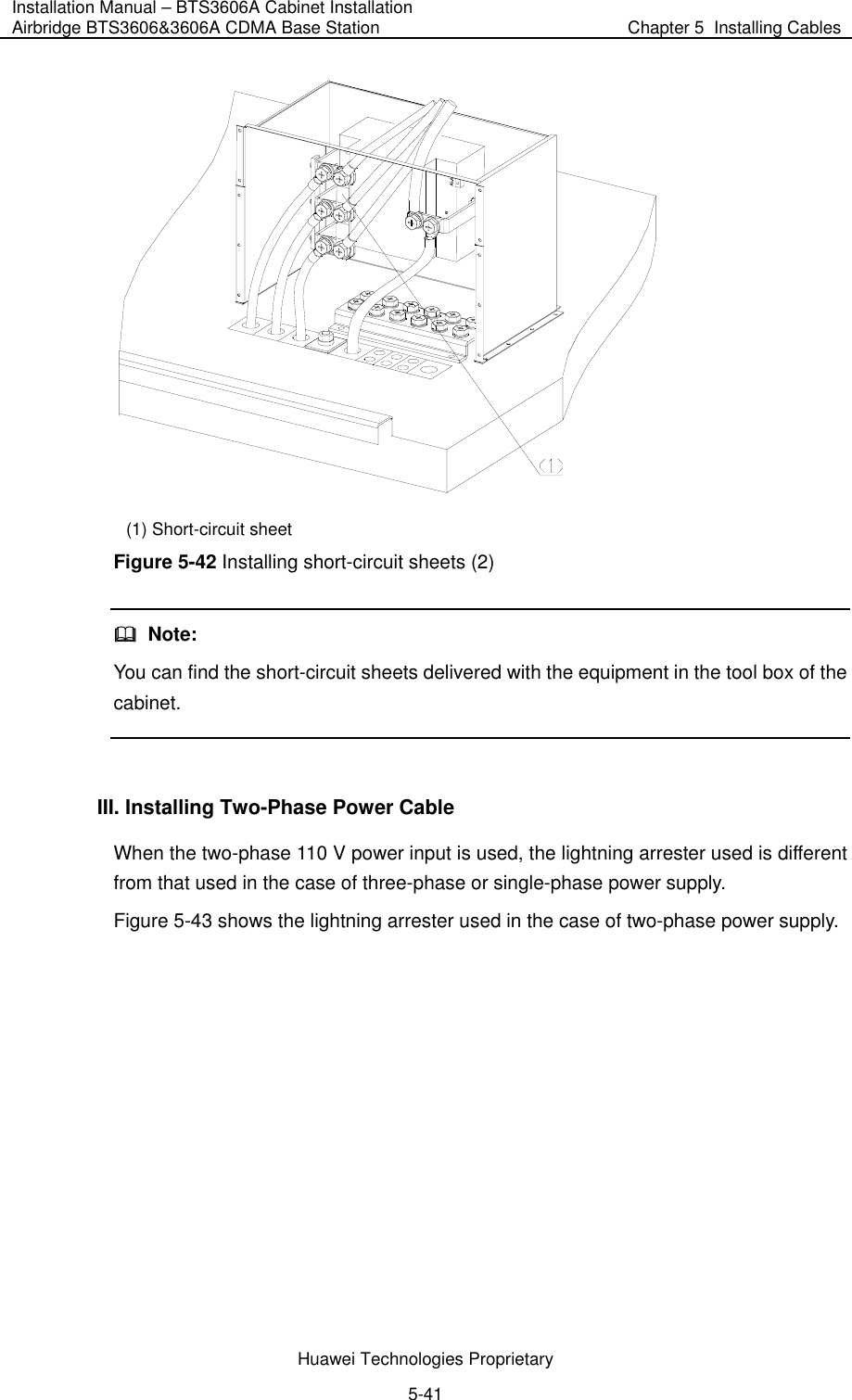
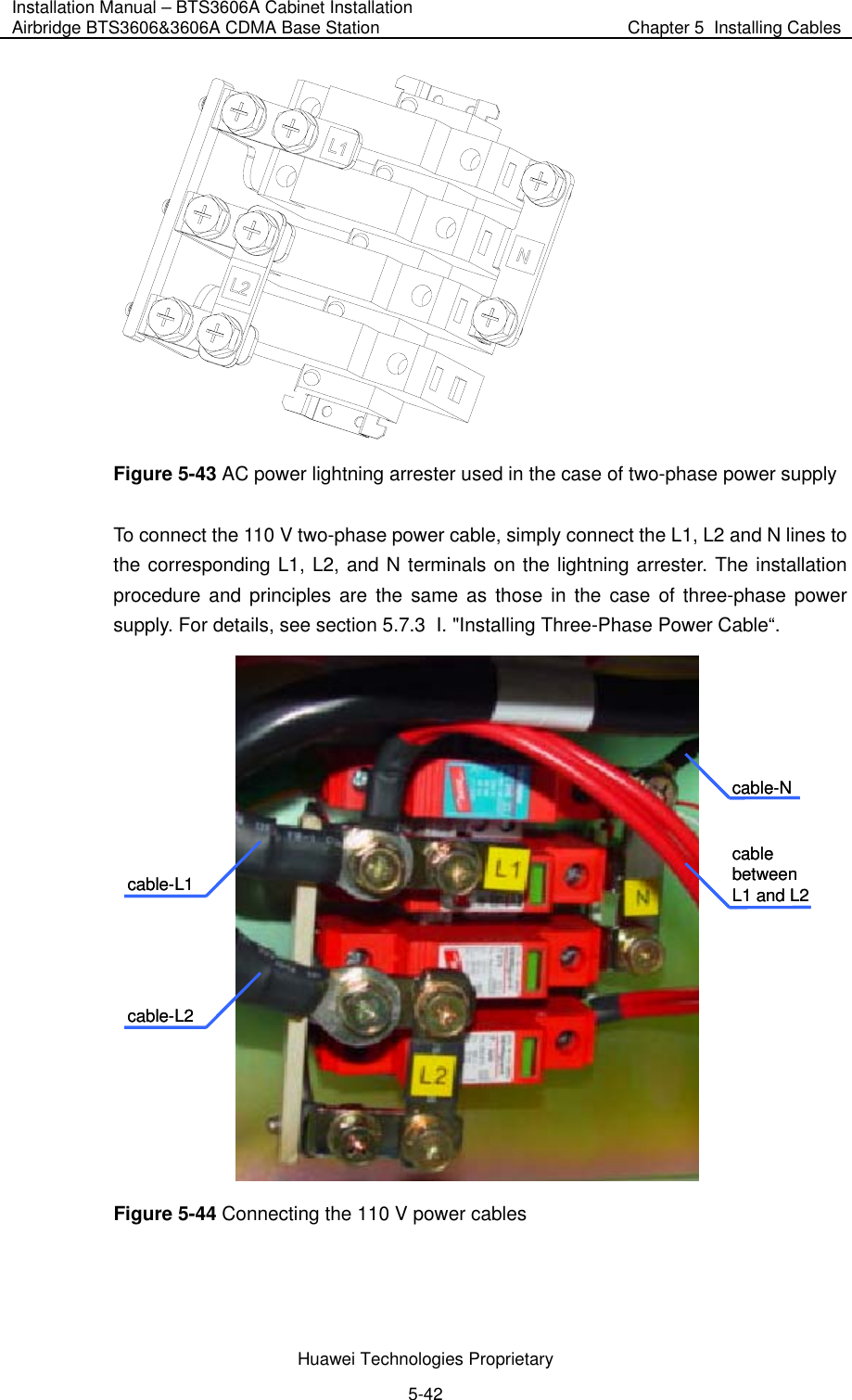
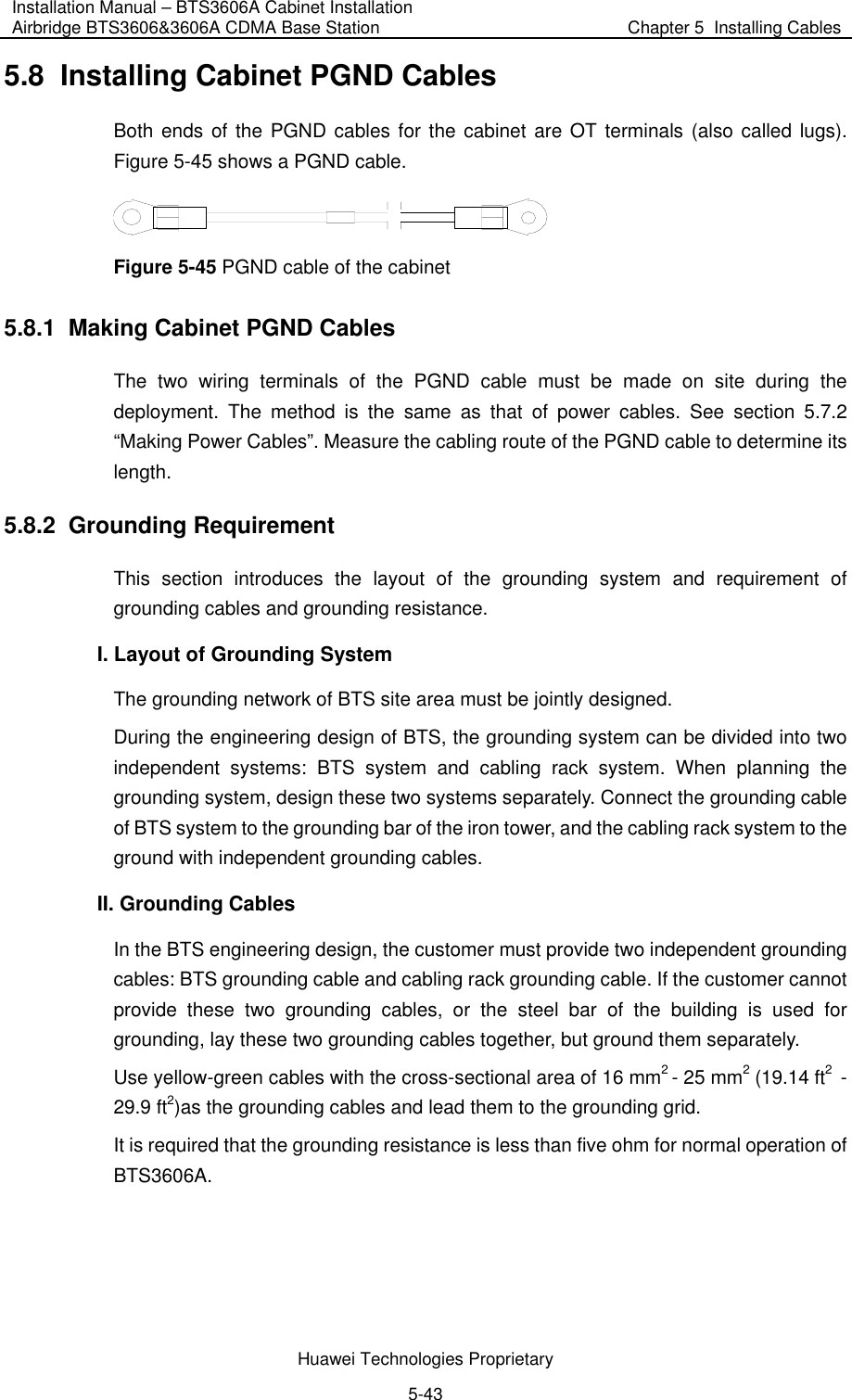
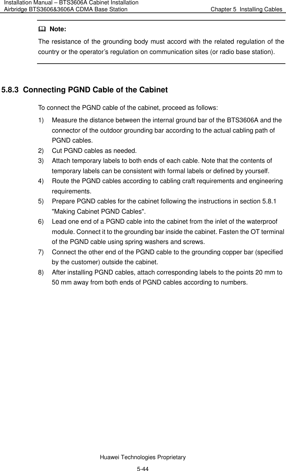
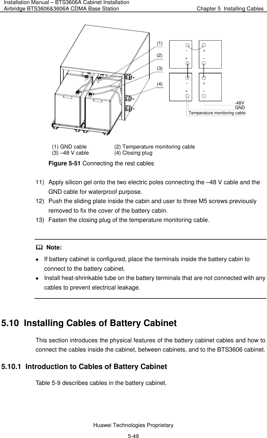
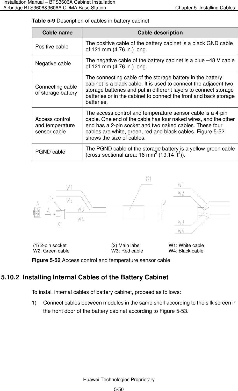
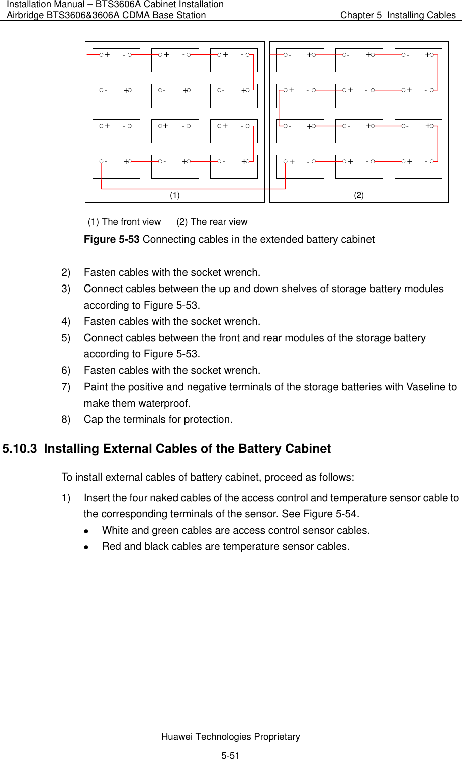
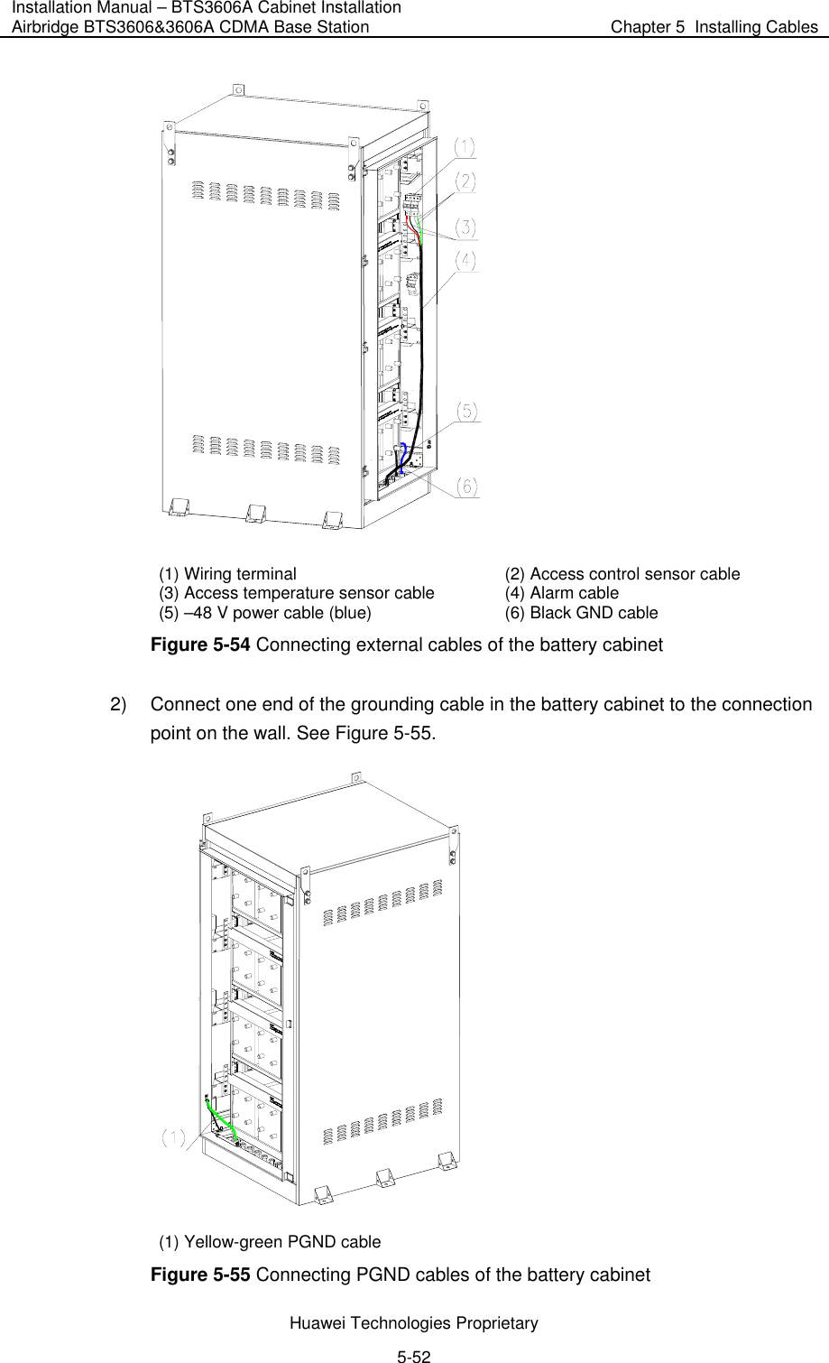
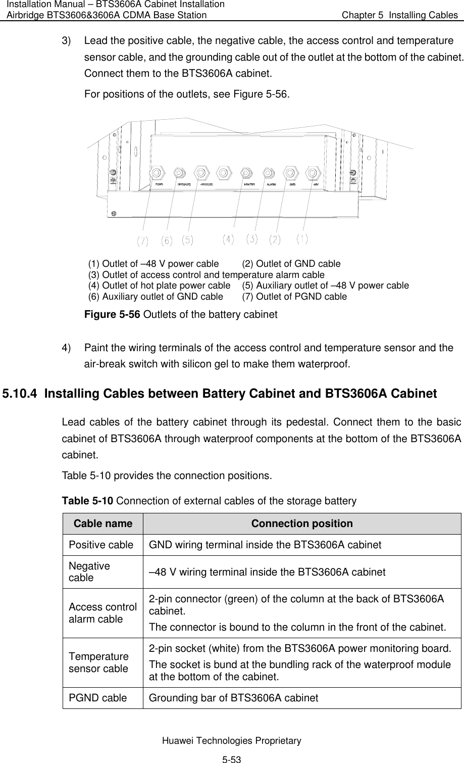
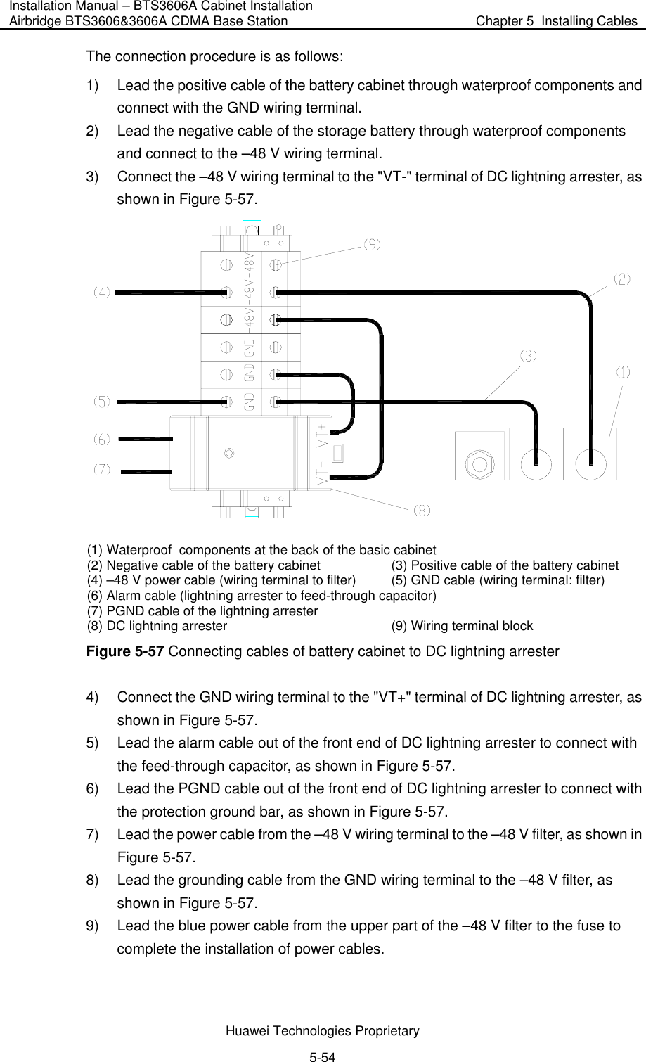
Huawei Technologies BTS3606A-1900D CDMA Base Station User Manual
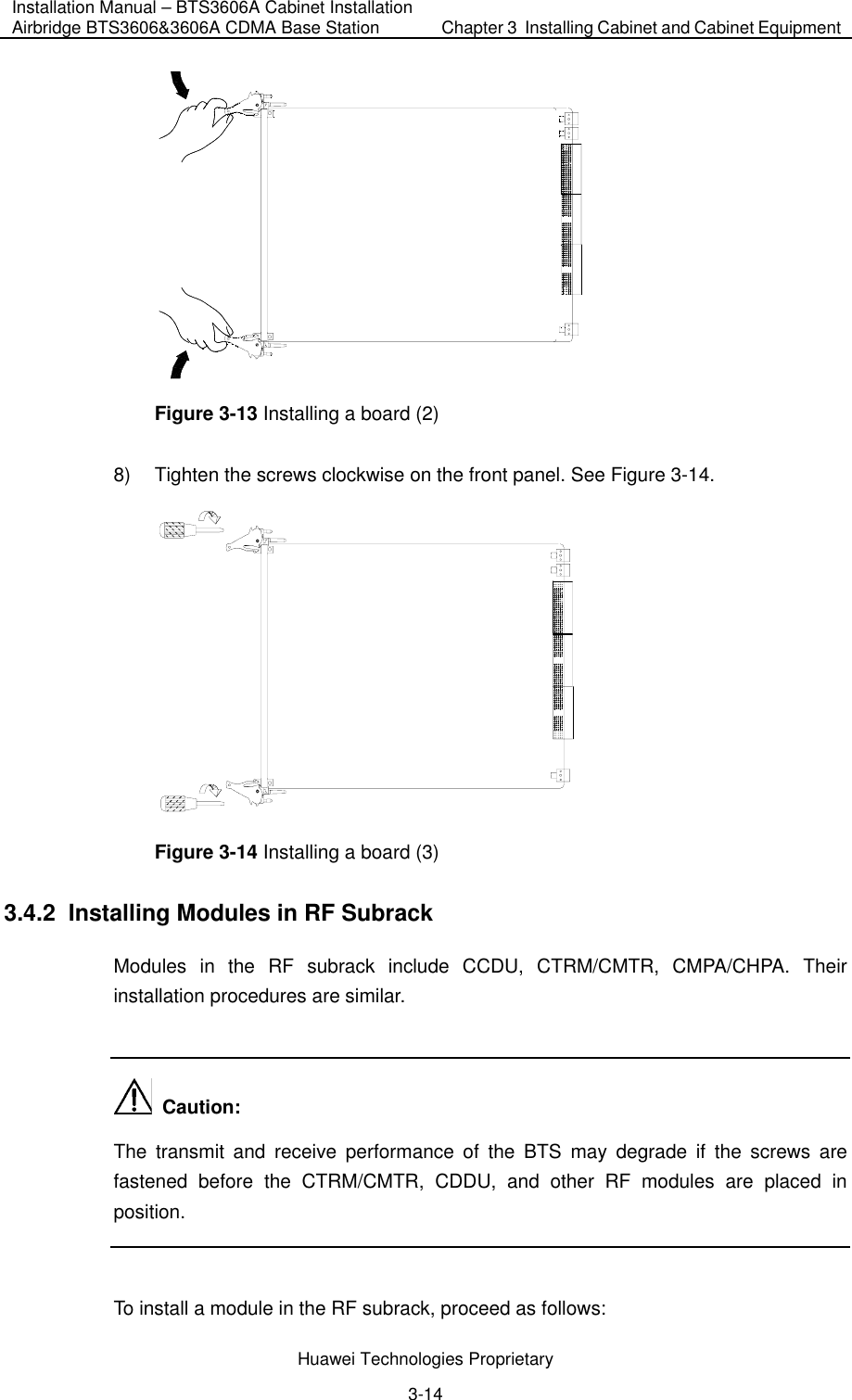
Huawei Technologies Co.,Ltd CDMA Base Station Users Manual
UserManual.wiki
>
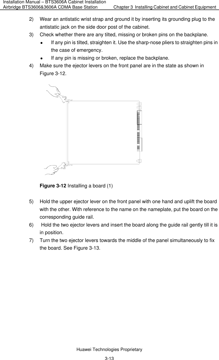
Huawei Technologies
>
BTS3606A 1900D User Manual
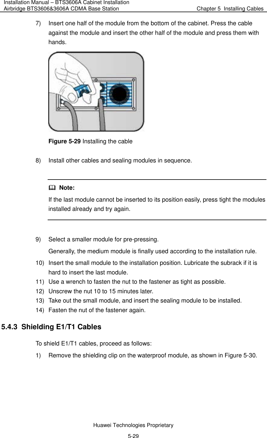
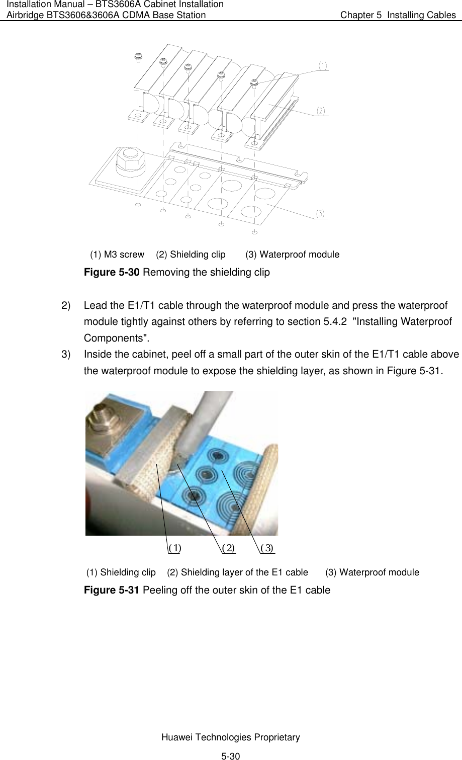
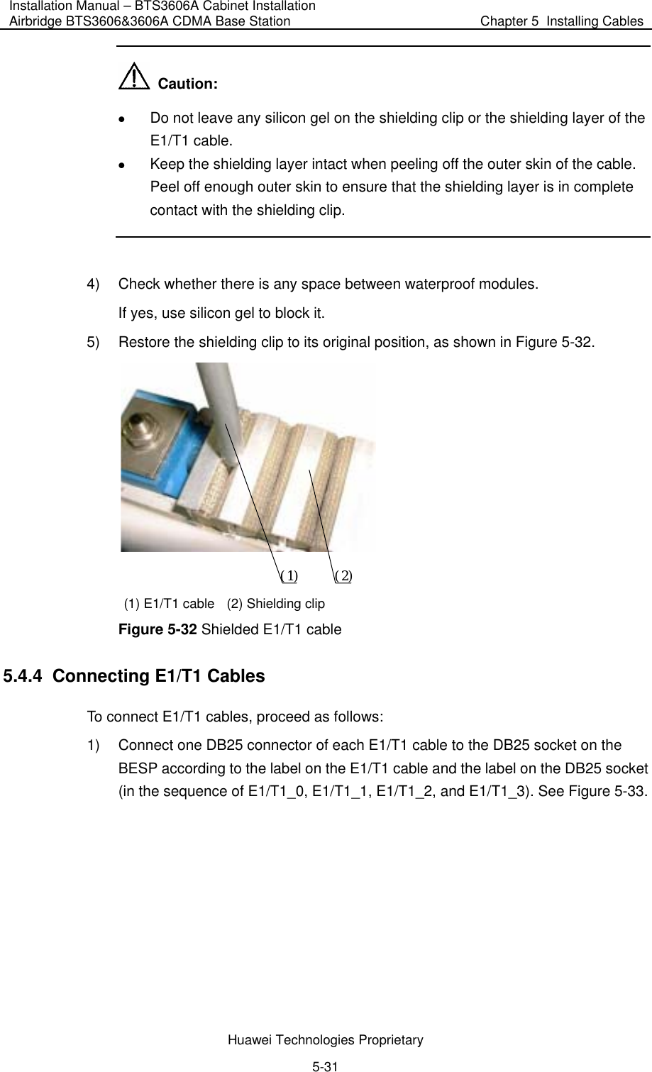
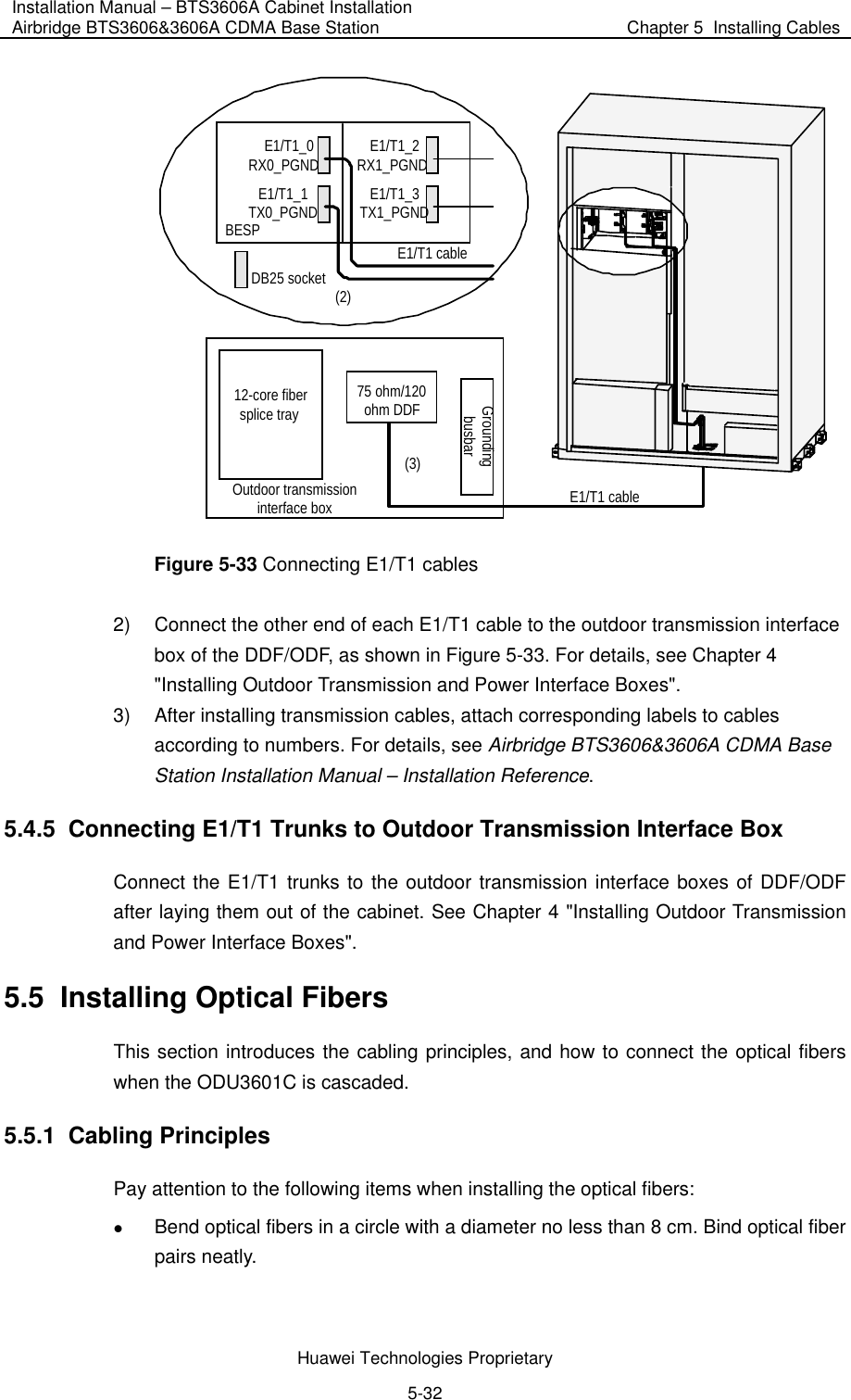
Users Manual
Navigation menu
Upload a User Manual
Namespaces
Wiki Guide
HTML
PDF
Info
Views
User Manual
Discussion / Help
Navigation
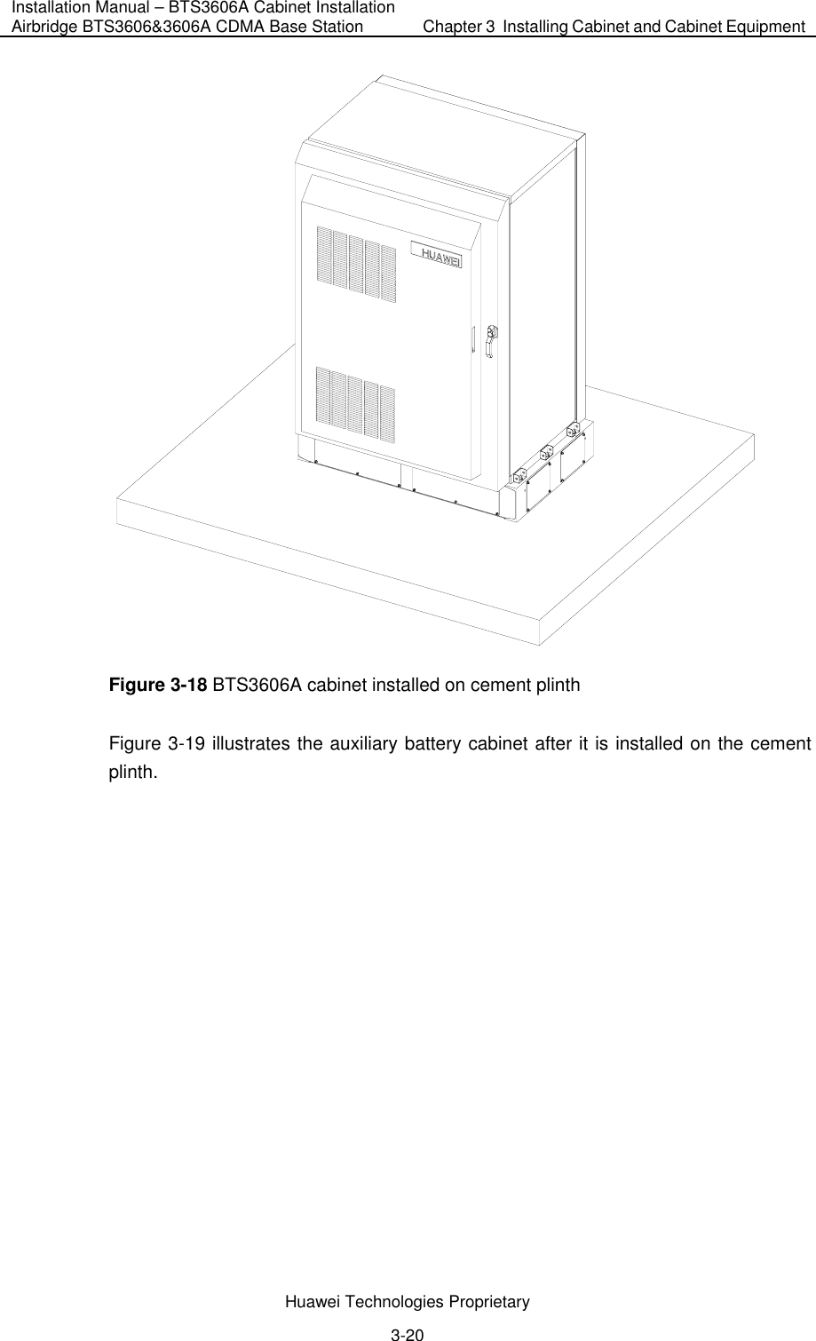
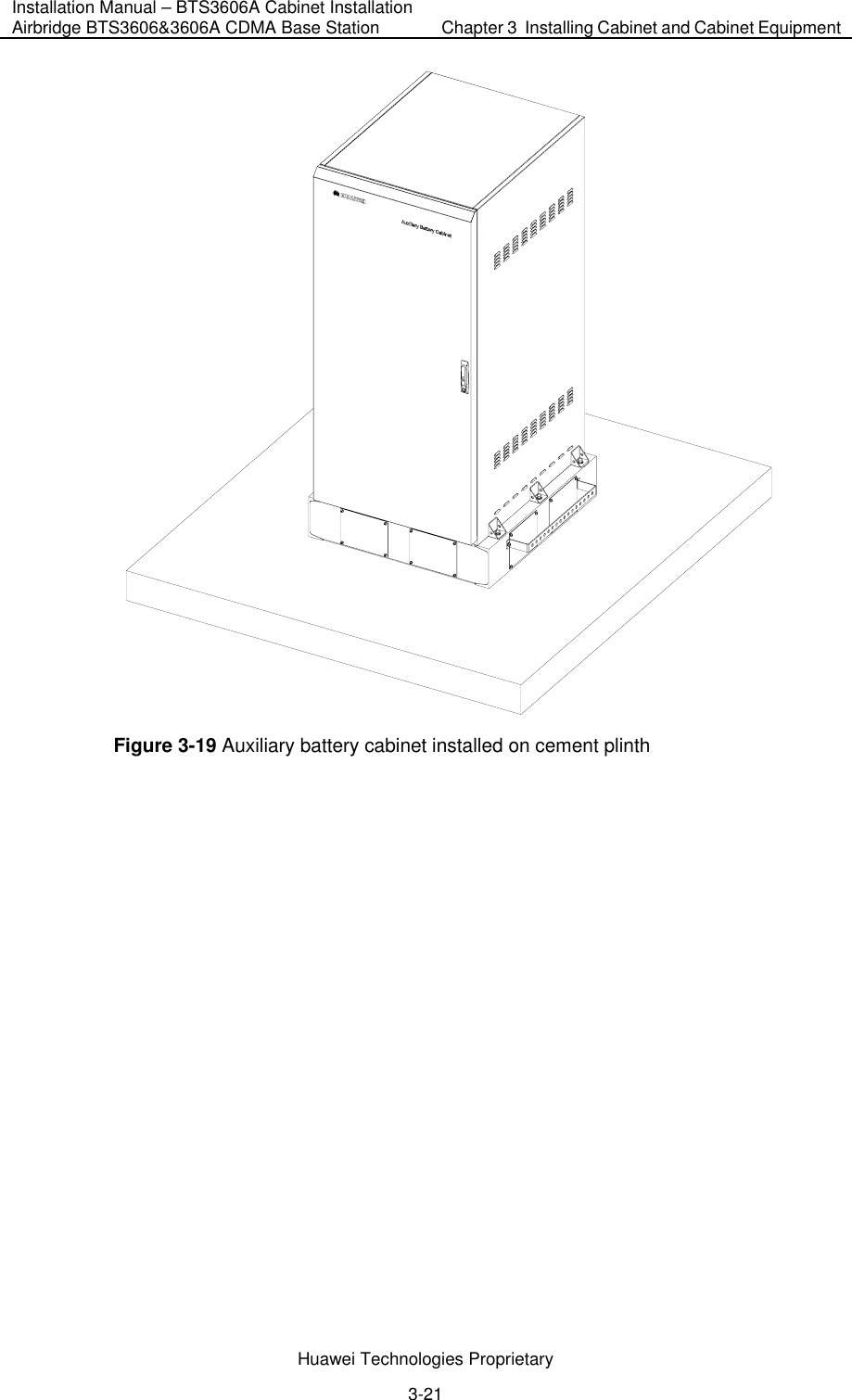
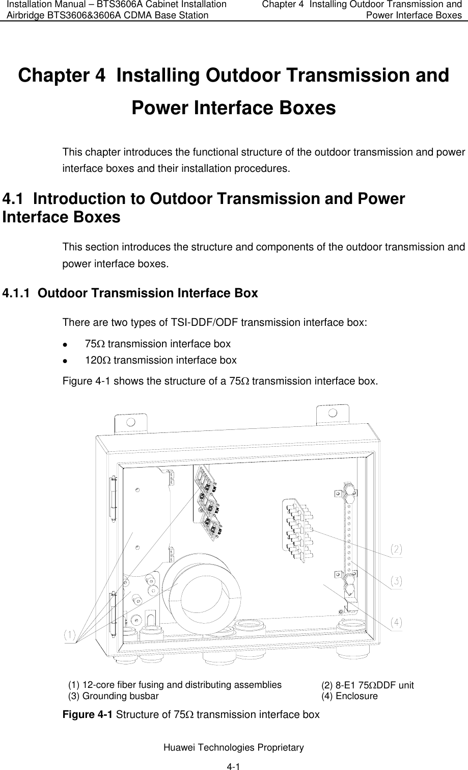
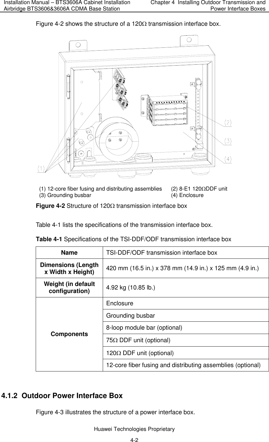
![Huawei Technologies Proprietary Chapter 3 Installing Cabinet and Cabinet Equipment introduces how to install the BTS3606A cabinet and the battery cabinet, how to install/remove the cabinet doors, and how to install the boards/modules and the batteries. Chapter 4 Installing Outdoor Transmission and Power Interface Boxes introduces the structures of the outdoor transmission and power interface boxes, the installation procedures, and the usage of the two interface boxes. Chapter 5 Installing Cables introduces the categories of cables installed on site, cable distribution methods, description of water-proof components, and procedures of connecting various cables in BTS3606A cabinet, battery cabinet, and combined cabinets. Chapter 6 Checking Cabinet Installation provides the installation checklists after the cabinet equipment is installed. Intended Audience The manual is intended for the following readers: z Installation engineers and technicians z Operation and maintenance personnel Conventions The manual uses the following conventions: I. General conventions Convention Description Arial Normal paragraphs are in Arial. Boldface Headings are in Boldface. Courier New Terminal Display is in Courier New. II. Command conventions Convention Description Boldface The keywords of a command line are in Boldface. italic Command arguments are in italic. [ ] Items (keywords or arguments) in square brackets [ ] are optional.](https://usermanual.wiki/Huawei-Technologies/BTS3606A-1900D/User-Guide-599189-Page-5.png)
![Huawei Technologies Proprietary Convention Description { x | y | ... } Alternative items are grouped in braces and separated by vertical bars. One is selected. [ x | y | ... ] Optional alternative items are grouped in square brackets and separated by vertical bars. One or none is selected. { x | y | ... } * Alternative items are grouped in braces and separated by vertical bars. A minimum of one or a maximum of all can be selected. [ x | y | ... ] * Optional alternative items are grouped in square brackets and separated by vertical bars. Many or none can be selected. # A line starting with the # sign is comments. III. GUI conventions Convention Description Boldface Button names and menu items are in Boldface. For example, click OK. / Multi-level menus are in bold and separated by forward slashes. For example, select the File/Create/Folder menu. Convention Description < > Button names are inside angle brackets. For example, click the <OK> button. [ ] Window names, menu items, data table and field names are inside square brackets. For example, pop up the [New User] window. / Multi-level menus are separated by forward slashes. For example, [File/Create/Folder]. IV. Keyboard operation Format Description <Key> Press the key with the key name inside angle brackets. For example, <Enter>, <Tab>, <Backspace>, or <A>. <Key1+Key2> Press the keys concurrently. For example, <Ctrl+Alt+A> means the three keys should be pressed concurrently. <Key1, Key2> Press the keys in turn. For example, <Alt, A> means the two keys should be pressed in turn.](https://usermanual.wiki/Huawei-Technologies/BTS3606A-1900D/User-Guide-599189-Page-6.png)