Huawei Technologies BTS3902E-U1900 Micro BTS User Manual Installation Guide
Huawei Technologies Co.,Ltd Micro BTS Installation Guide
UserManual.wiki
>
Huawei Technologies
>
BTS3902E U1900 User Manual
Installation Guide
Navigation menu
Upload a User Manual
Namespaces
Wiki Guide
HTML
PDF
Info
Views
User Manual
Discussion / Help
Navigation
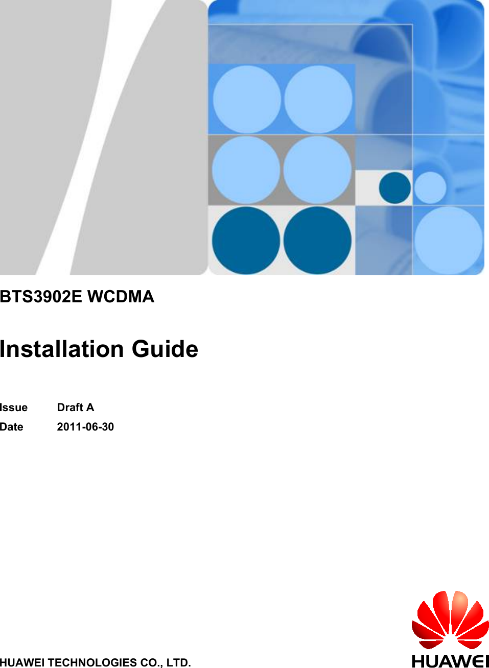


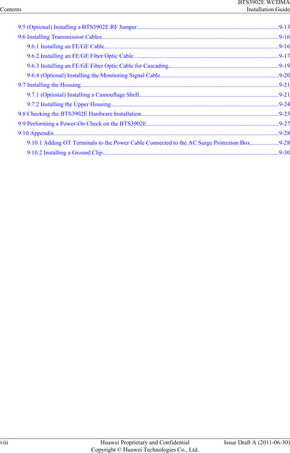
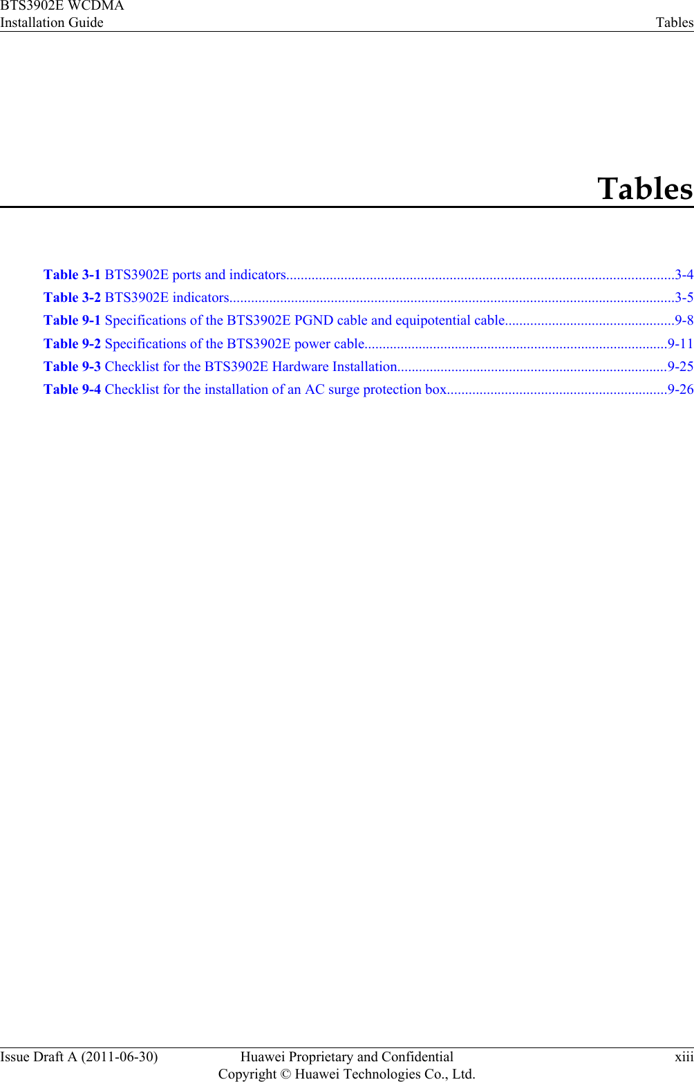
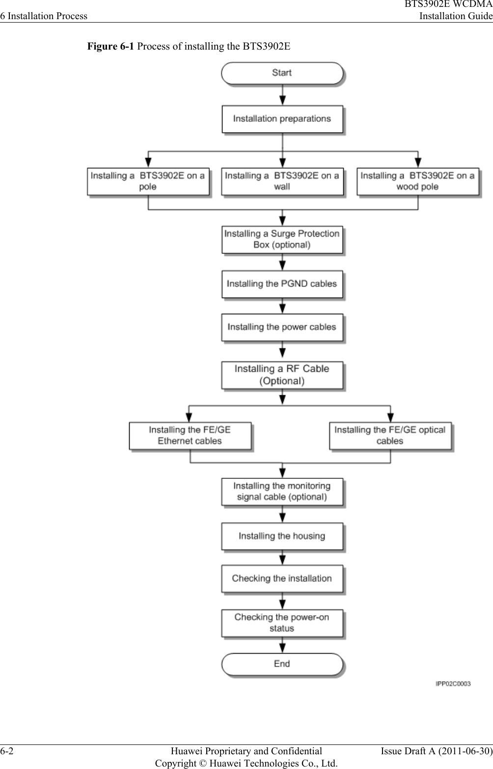
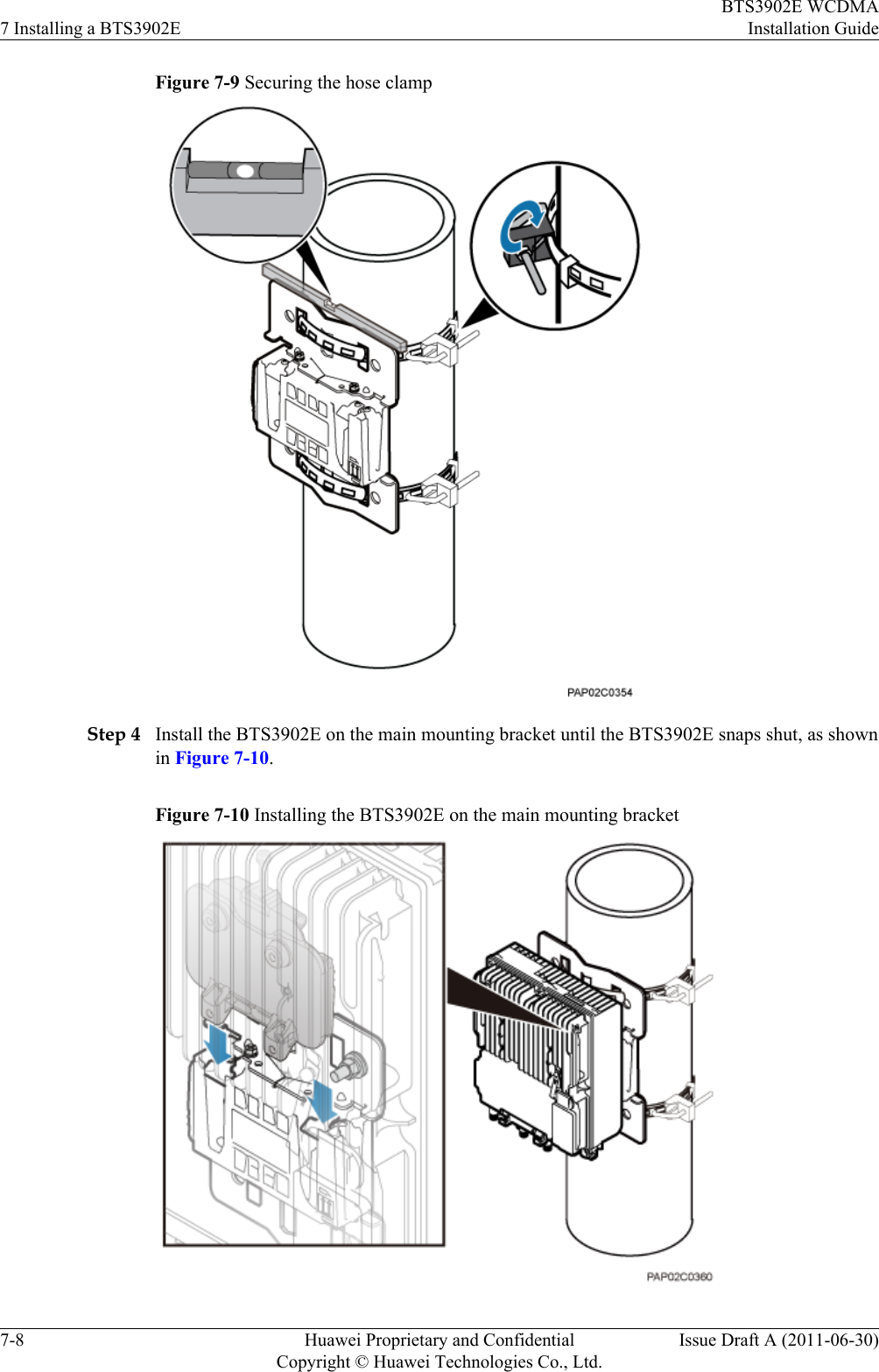
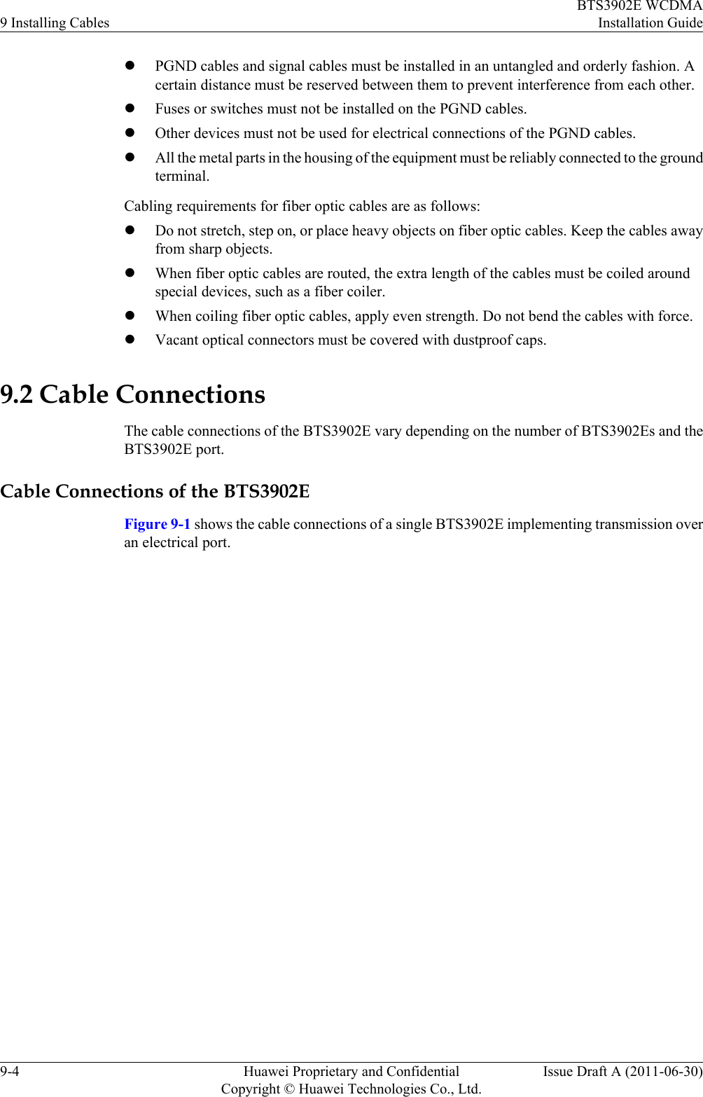
![The general conventions that may be found in this document are defined as follows.Convention DescriptionTimes New Roman Normal paragraphs are in Times New Roman.Boldface Names of files, directories, folders, and users are inboldface. For example, log in as user root.Italic Book titles are in italics.Courier New Examples of information displayed on the screen are inCourier New. Command ConventionsThe command conventions that may be found in this document are defined as follows.Convention DescriptionBoldface The keywords of a command line are in boldface.Italic Command arguments are in italics.[ ] Items (keywords or arguments) in brackets [ ] are optional.{ x | y | ... } Optional items are grouped in braces and separated byvertical bars. One item is selected.[ x | y | ... ] Optional items are grouped in brackets and separated byvertical bars. One item is selected or no item is selected.{ x | y | ... }*Optional items are grouped in braces and separated byvertical bars. A minimum of one item or a maximum of allitems can be selected.[ x | y | ... ]*Optional items are grouped in brackets and separated byvertical bars. Several items or no item can be selected. GUI ConventionsThe GUI conventions that may be found in this document are defined as follows.Convention DescriptionBoldface Buttons, menus, parameters, tabs, window, and dialog titlesare in boldface. For example, click OK.>Multi-level menus are in boldface and separated by the ">"signs. For example, choose File > Create > Folder. Keyboard OperationsBTS3902E WCDMAInstallation Guide About This DocumentIssue Draft A (2011-06-30) Huawei Proprietary and ConfidentialCopyright © Huawei Technologies Co., Ltd.v](https://usermanual.wiki/Huawei-Technologies/BTS3902E-U1900/User-Guide-1487677-Page-7.png)
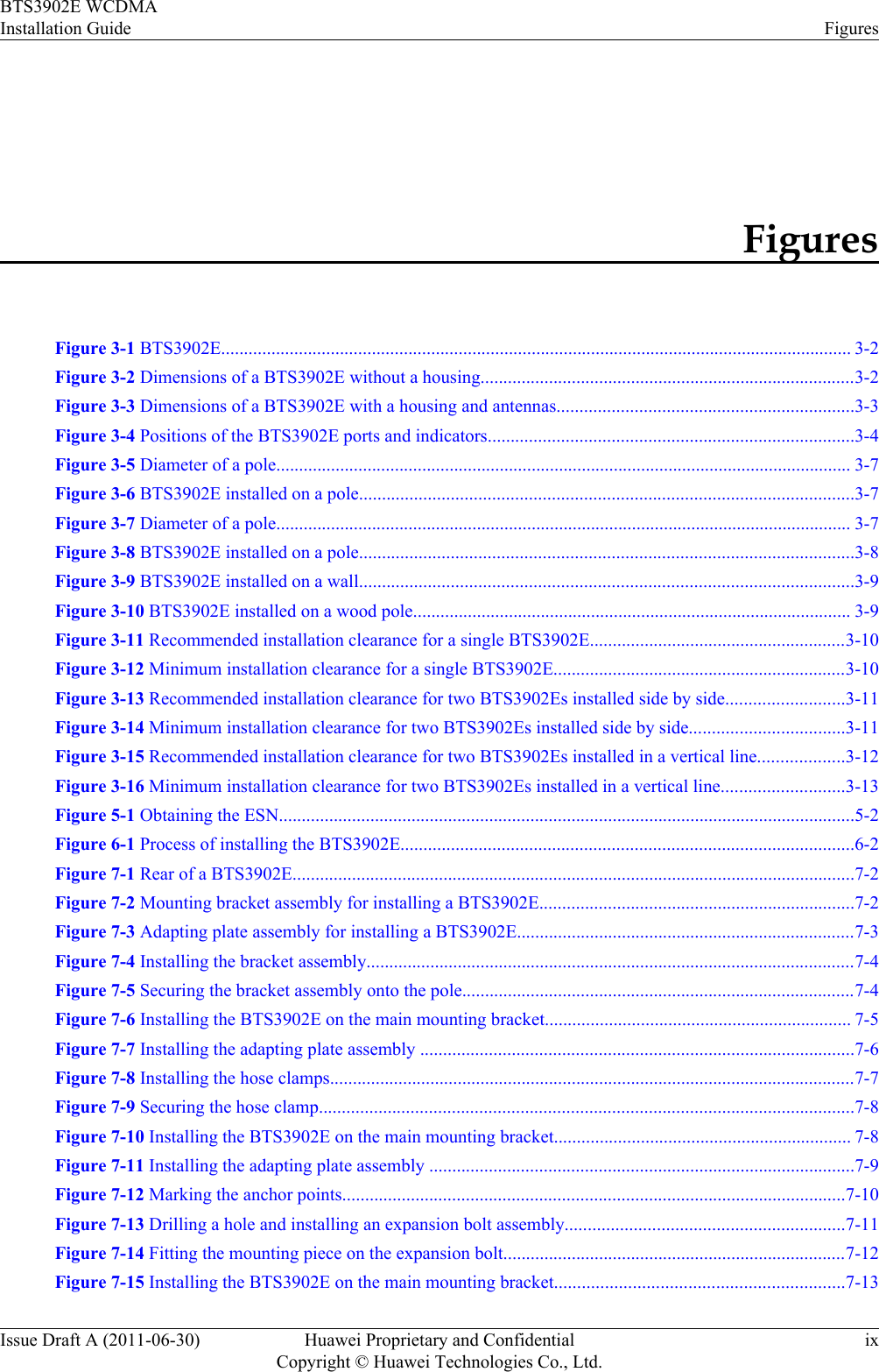
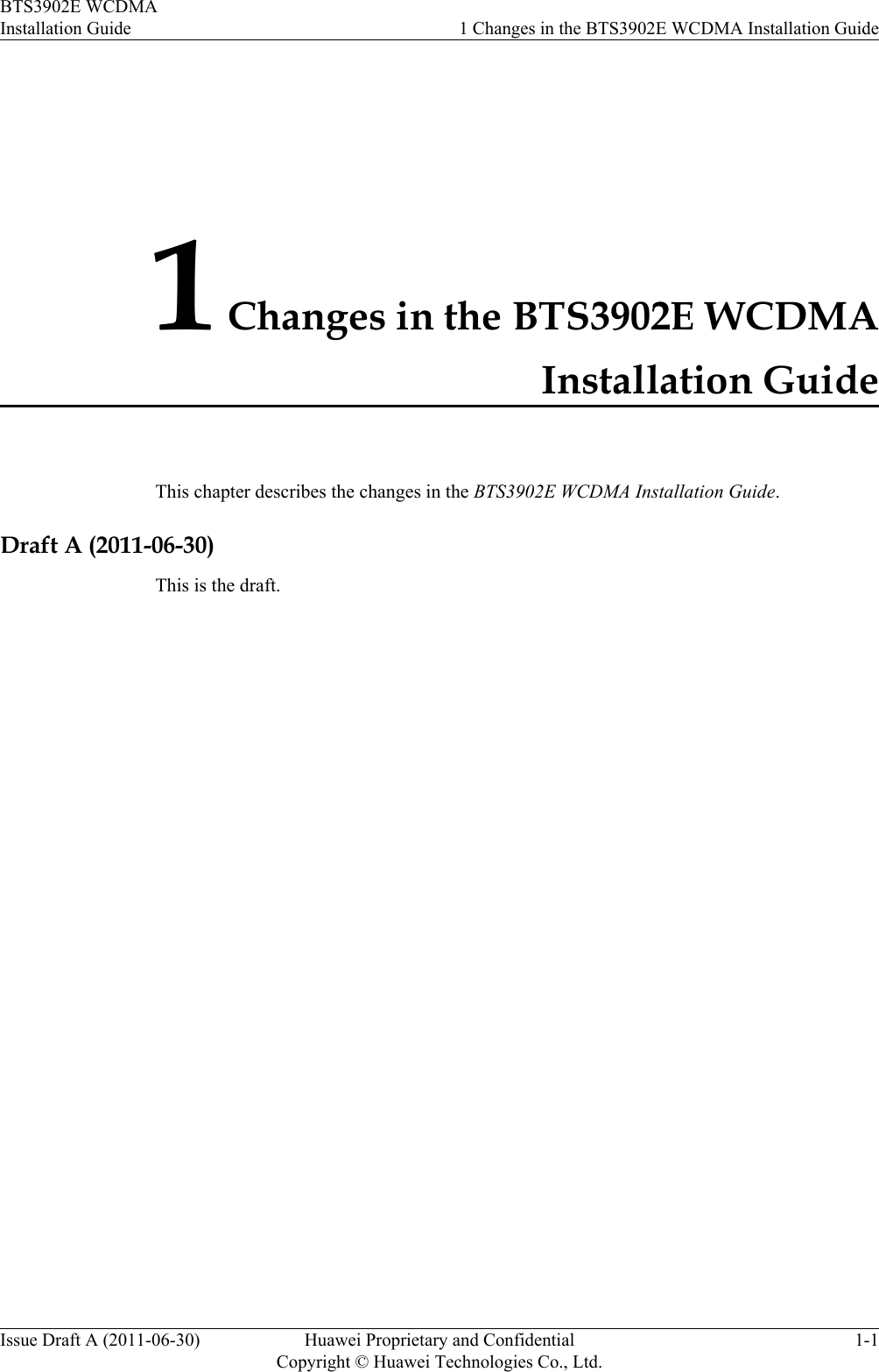
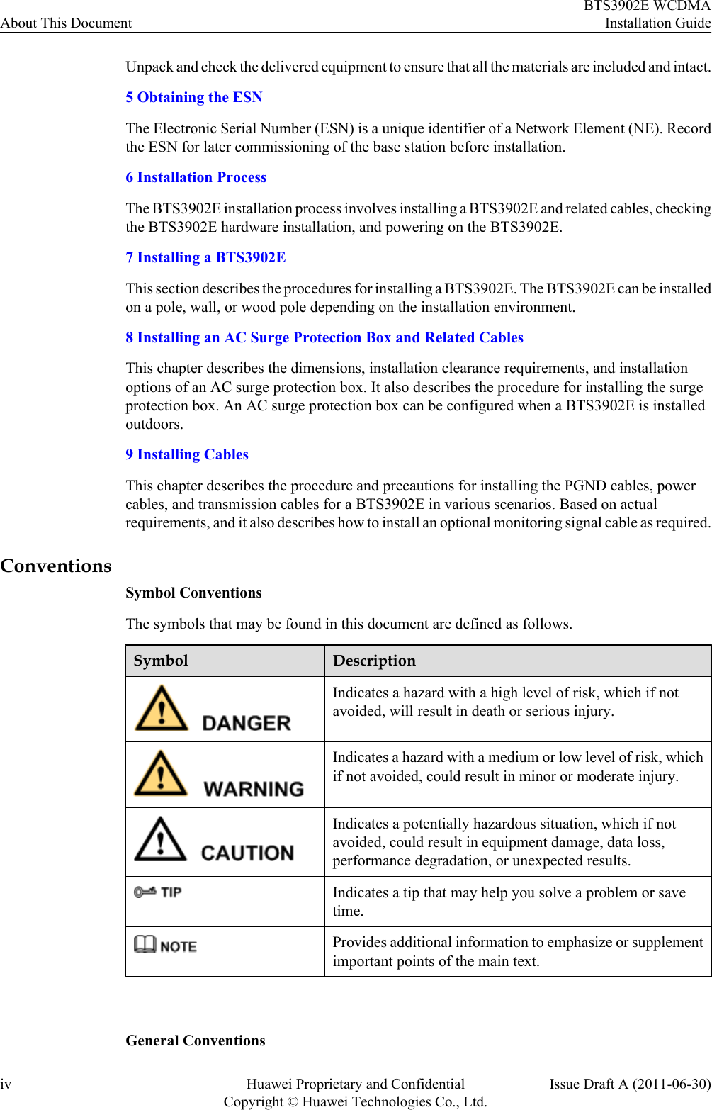
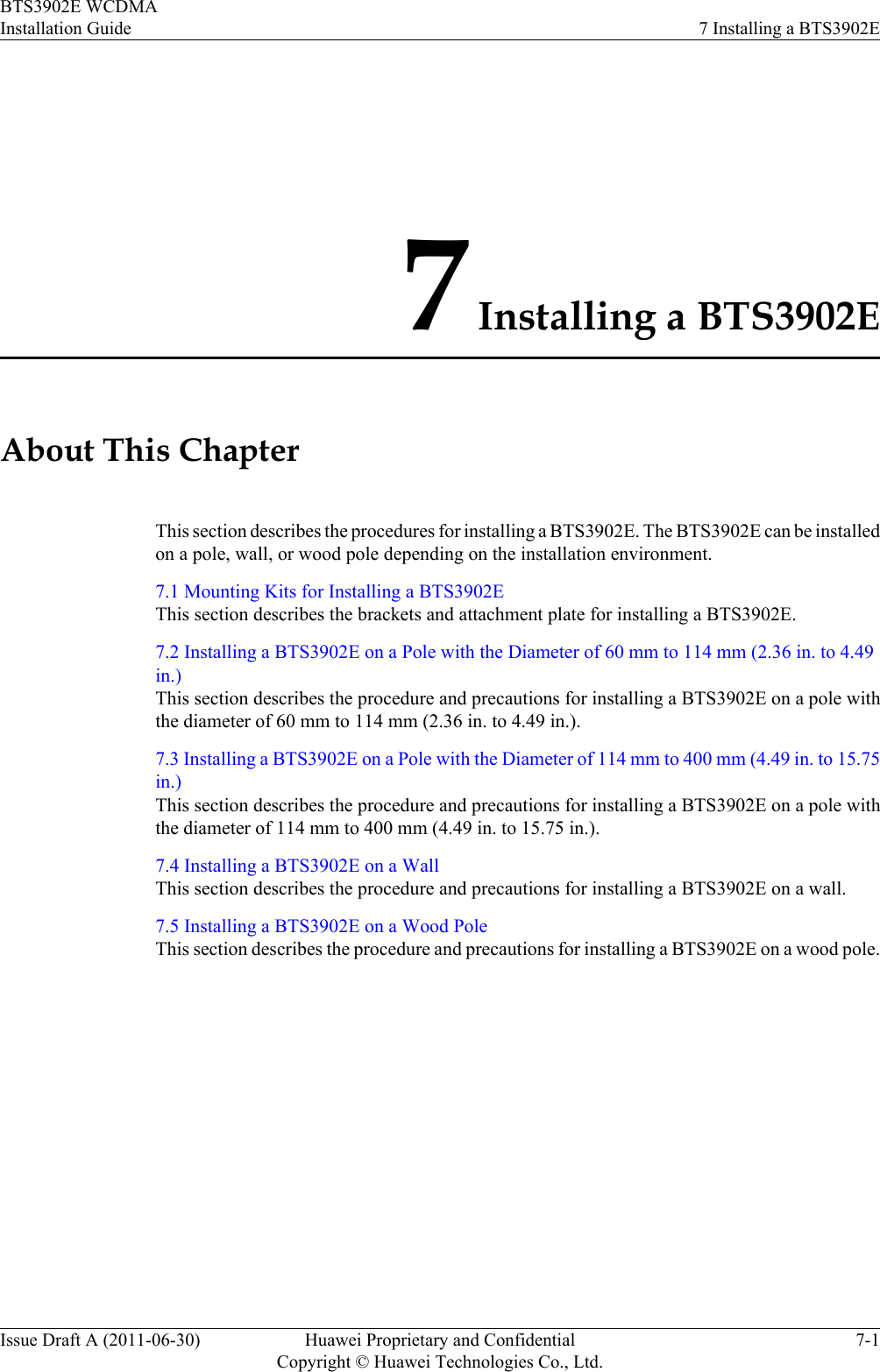
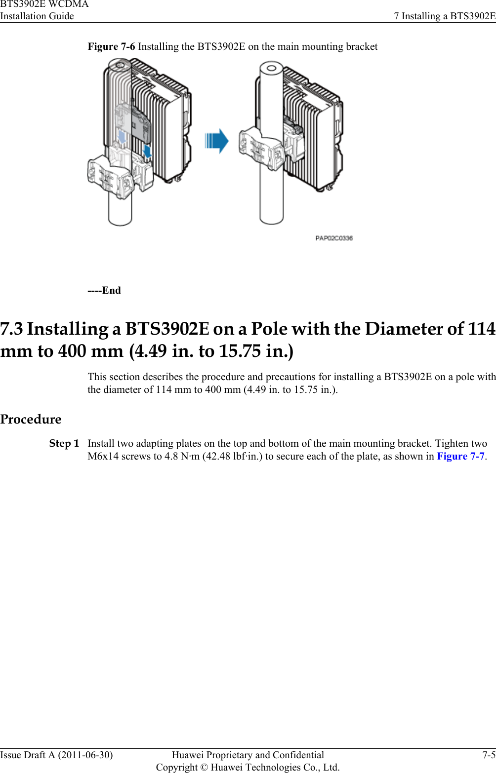
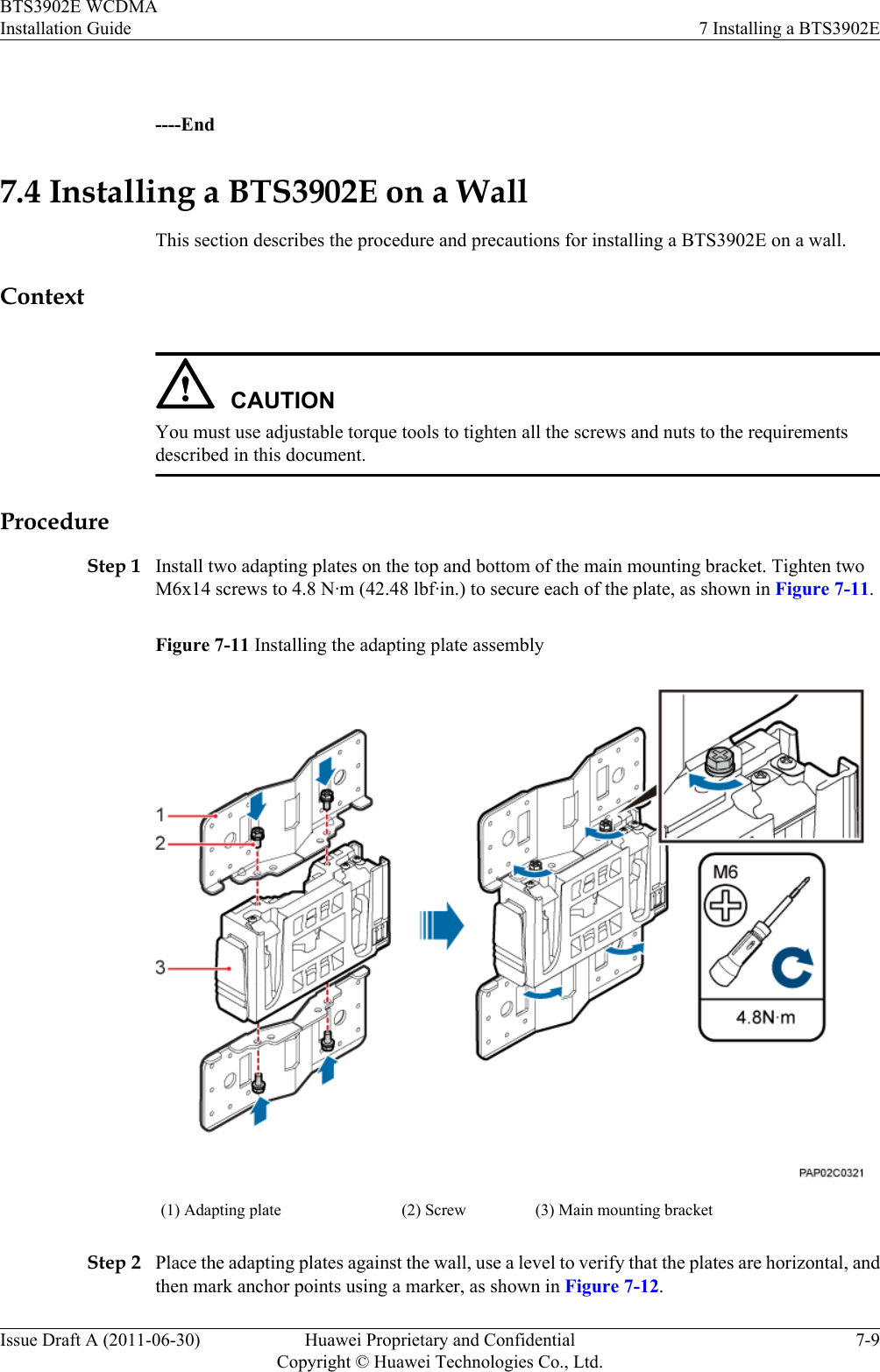
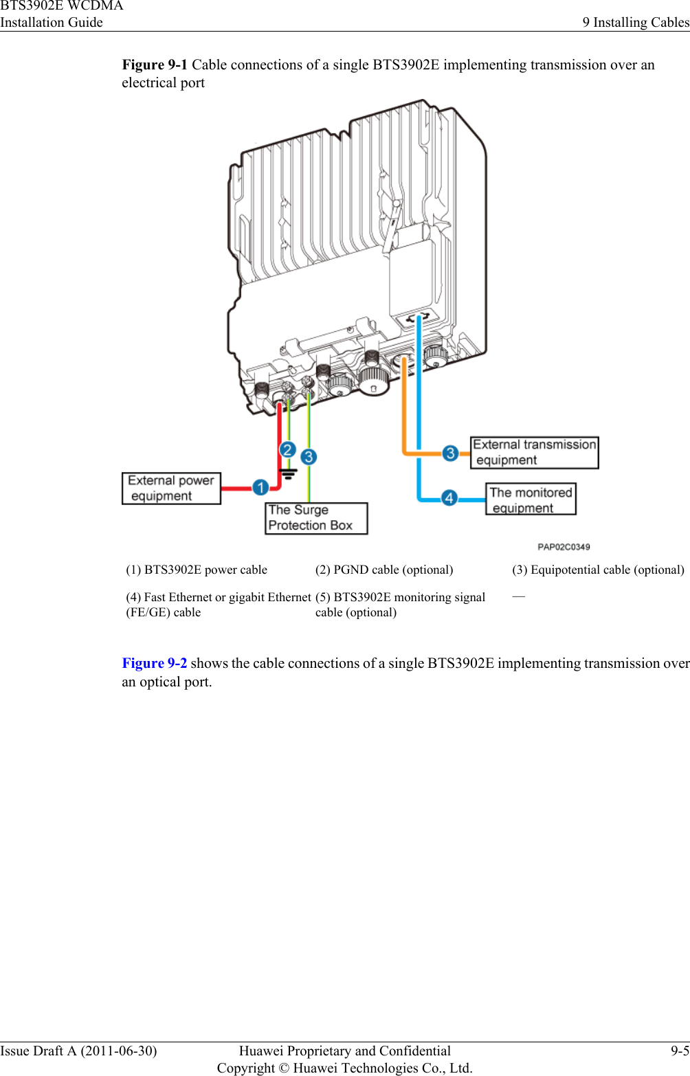
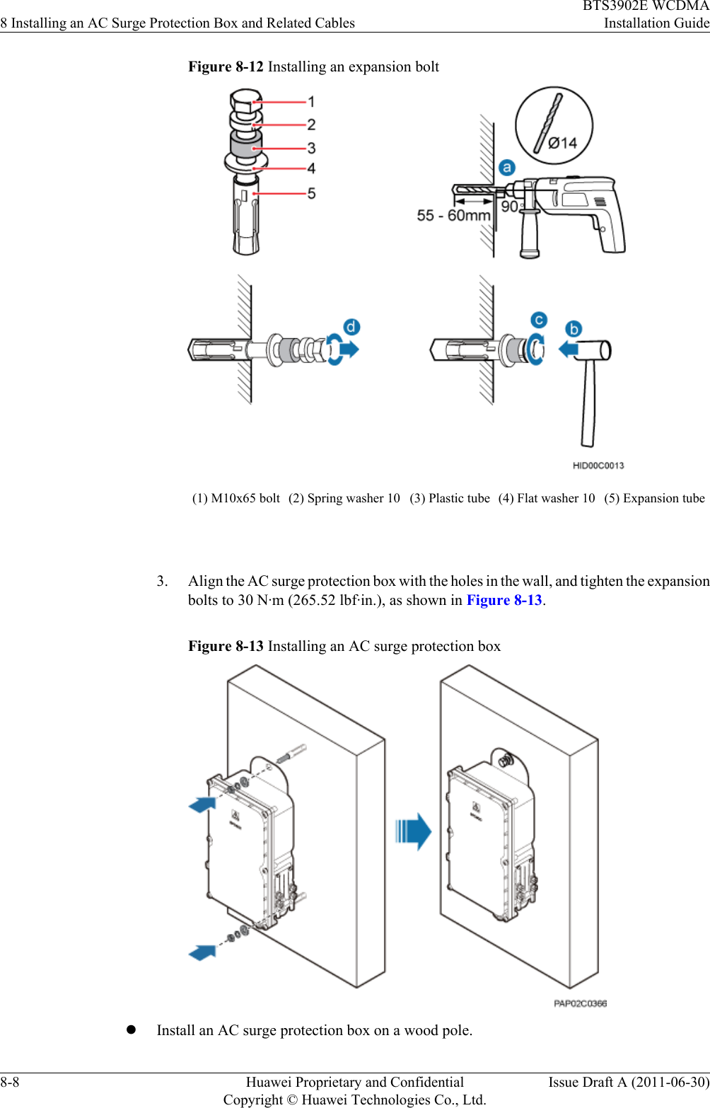
![2.1 Tools and InstrumentsAll required tools and instruments must be ready before the installation.Hammer drill (with a φ 12bit, φ 14 bit, and φ 18 bit)Electrostatic discharge(ESD) glovesVacuum cleanerHeat gun Phillips screwdriver (M3 toM6)Flat-head screwdriver (M3 toM6)Rubber mallet COAX crimping tool Wire stripperUtility knife Wire clippers Adjustable wrench (capacity≥ 32 mm [1.26 in.])Level Torque screwdriver5 mm (0.2 in.)(M3 to M6)(M3 to M6)Torque wrenchCapacity: 17 mm (0.67 in.) or21 mm (0.83 in.)Combination wrenchCapacity: 17 mm [0.67 in.] or21 mm [0.83 in.]Inner hexagon wrench Measuring tape2 Installation PreparationsBTS3902E WCDMAInstallation Guide2-2 Huawei Proprietary and ConfidentialCopyright © Huawei Technologies Co., Ltd.Issue Draft A (2011-06-30)](https://usermanual.wiki/Huawei-Technologies/BTS3902E-U1900/User-Guide-1487677-Page-20.png)
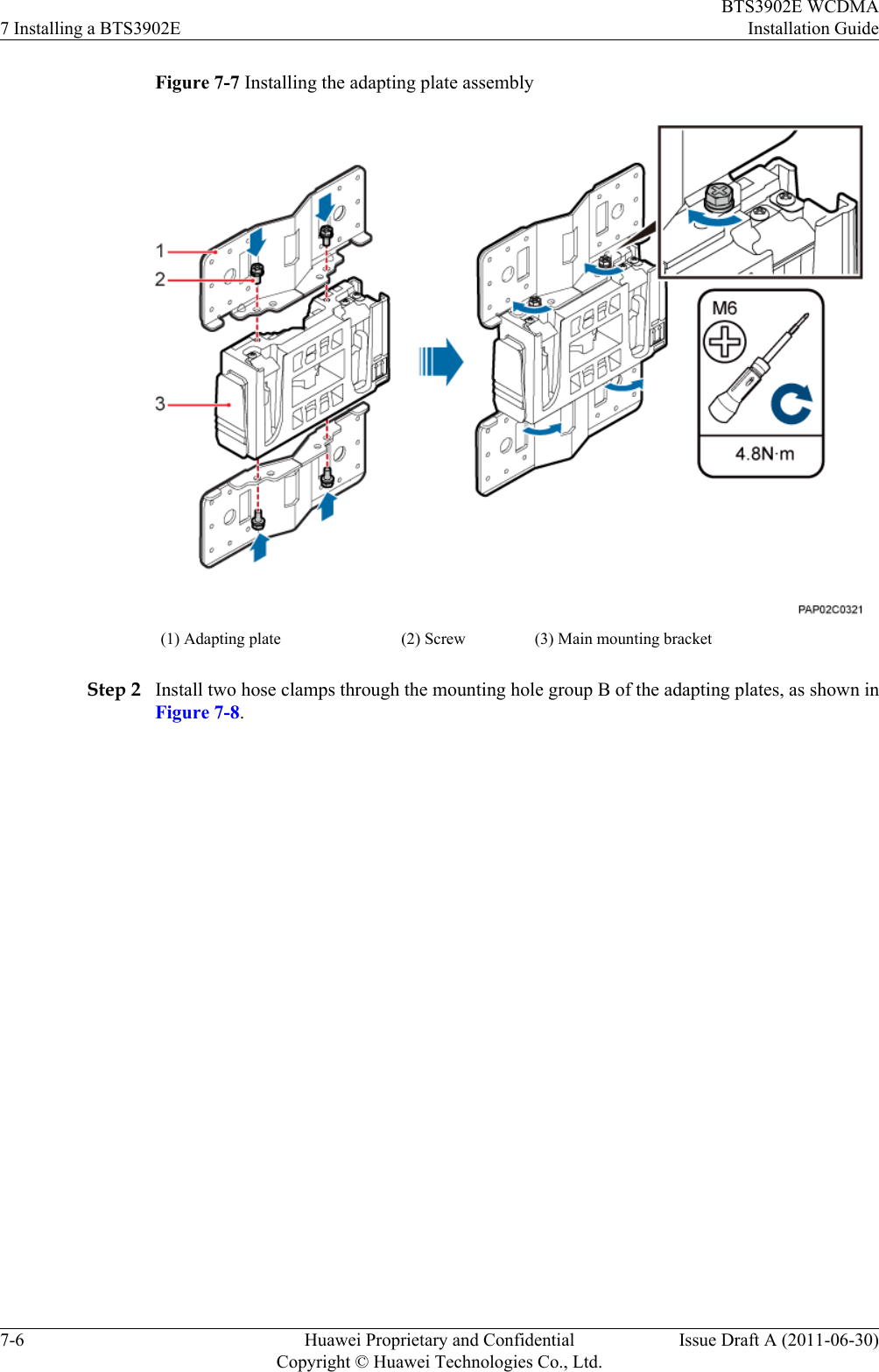
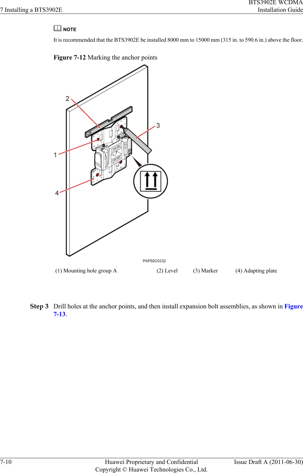
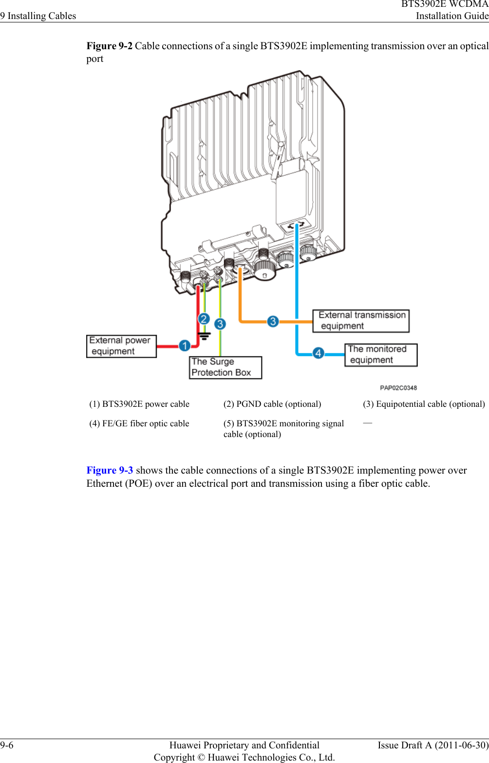
![Multimeter Marker (diameter ≤ 10 mm[0.39 in.])— 2.2 Skills and Requirements for Onsite PersonnelOnsite personnel must be qualified and trained. Before performing any operation, onsitepersonnel must be familiar with correct operation methods and safety precautions.Before the installation, pay attention to the following items:lThe customer's technical engineers must be trained by Huawei and be familiar with theproper installation and operation methods.lThe number of onsite personnel depends on the engineering schedule and installationenvironment. Generally, only three to five onsite personnel are necessary.BTS3902E WCDMAInstallation Guide 2 Installation PreparationsIssue Draft A (2011-06-30) Huawei Proprietary and ConfidentialCopyright © Huawei Technologies Co., Ltd.2-3](https://usermanual.wiki/Huawei-Technologies/BTS3902E-U1900/User-Guide-1487677-Page-21.png)

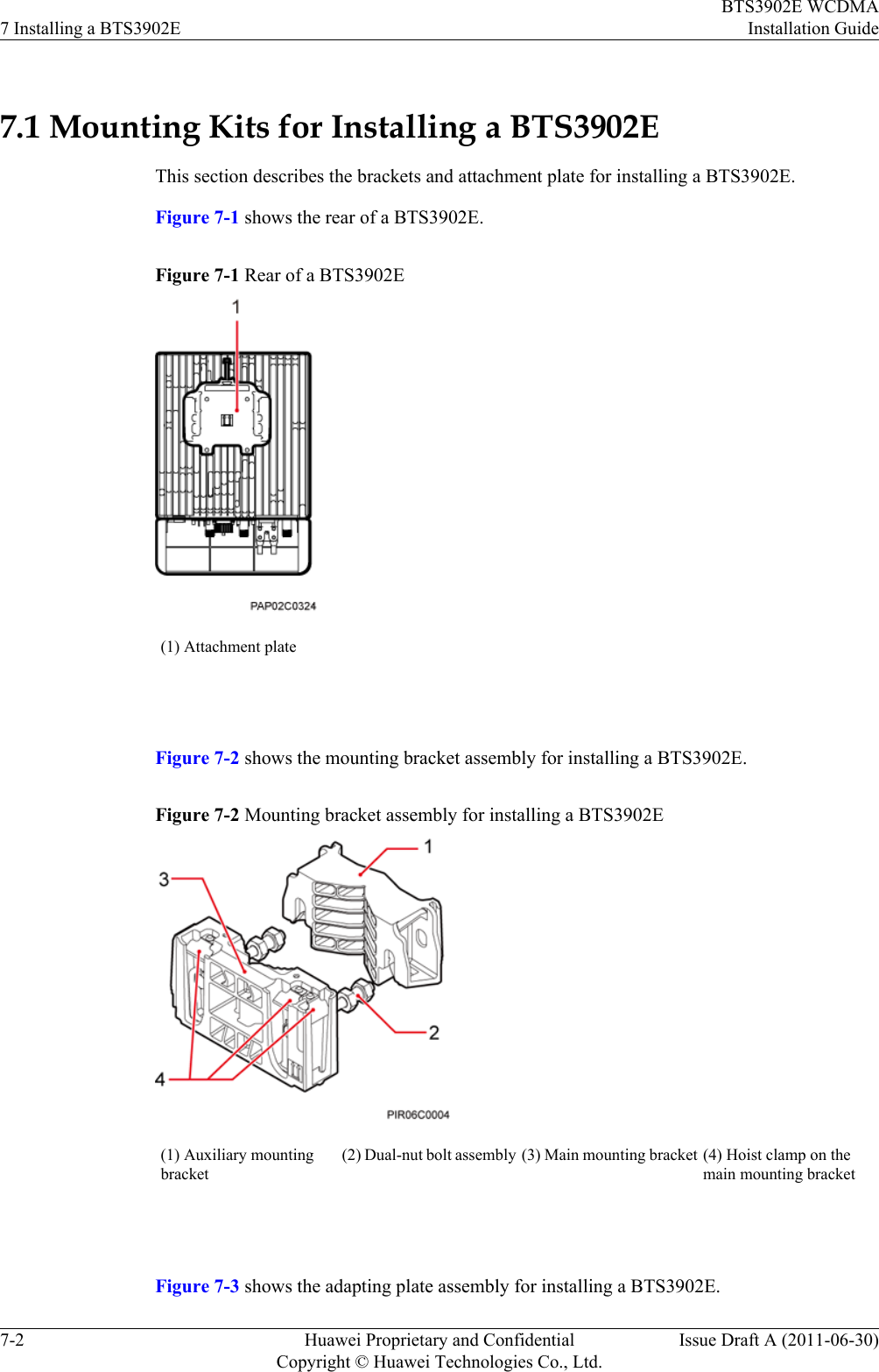
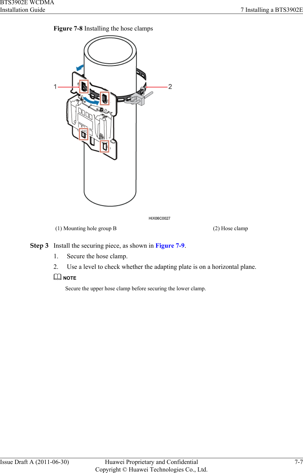
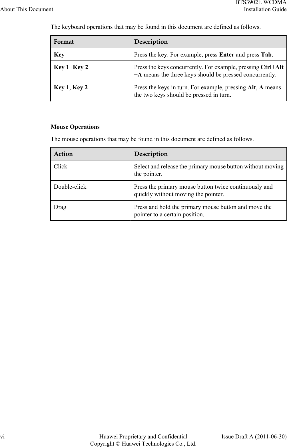
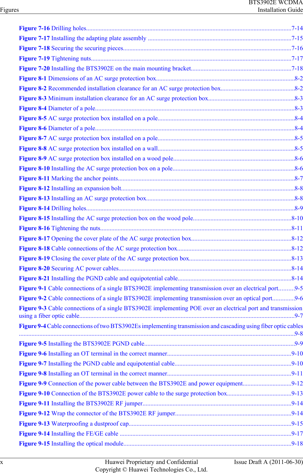
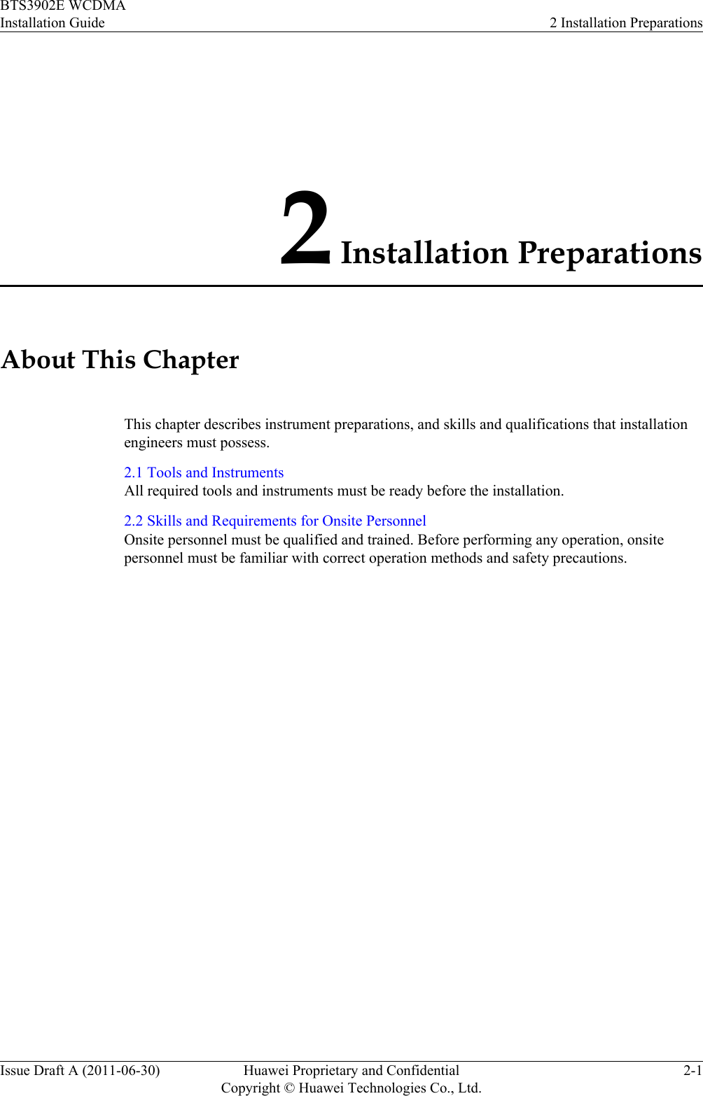
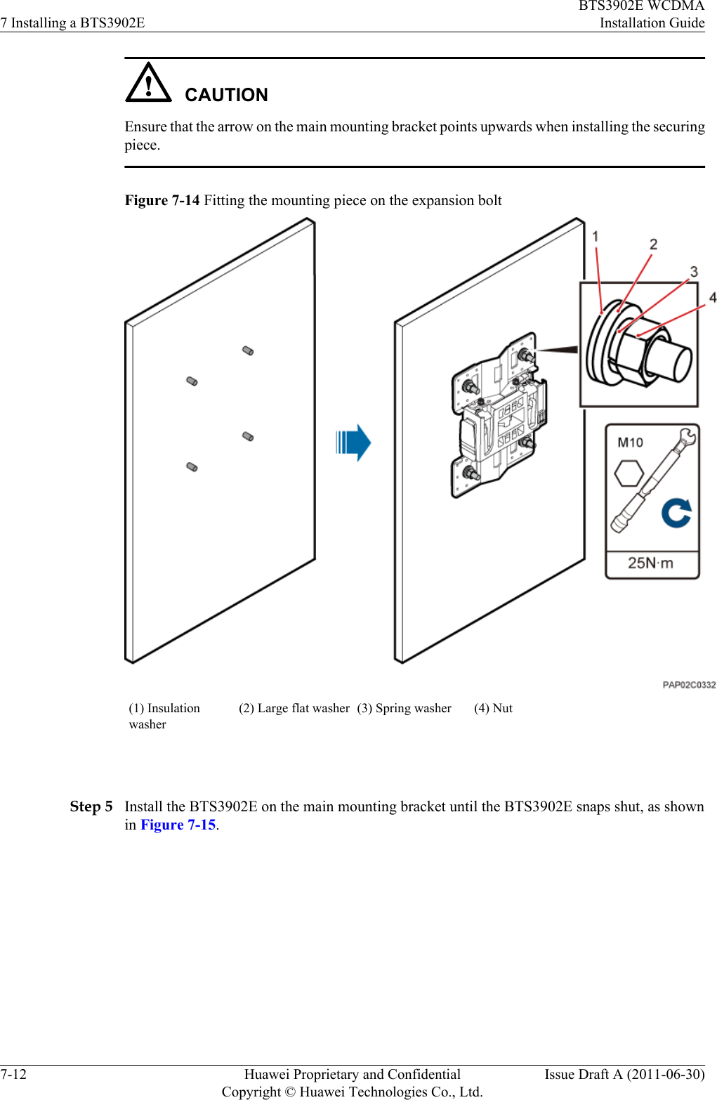
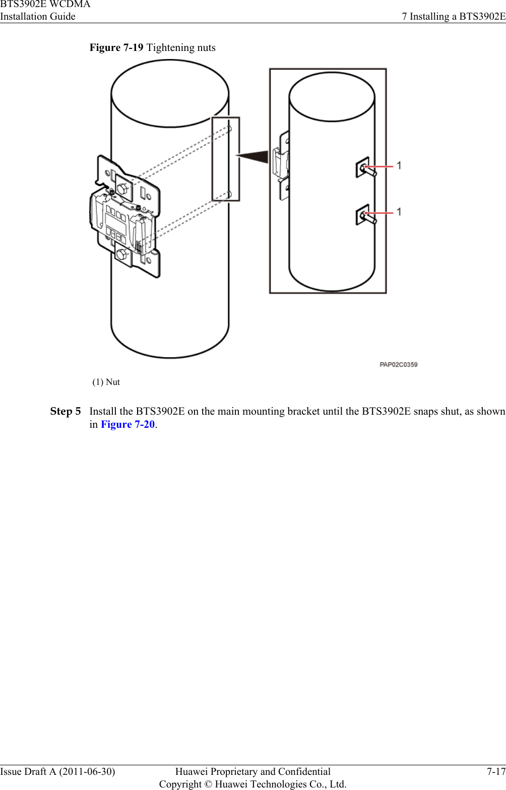
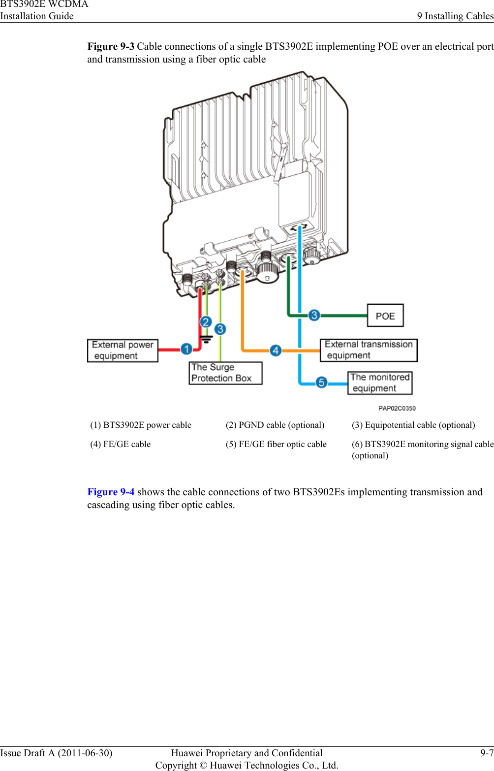
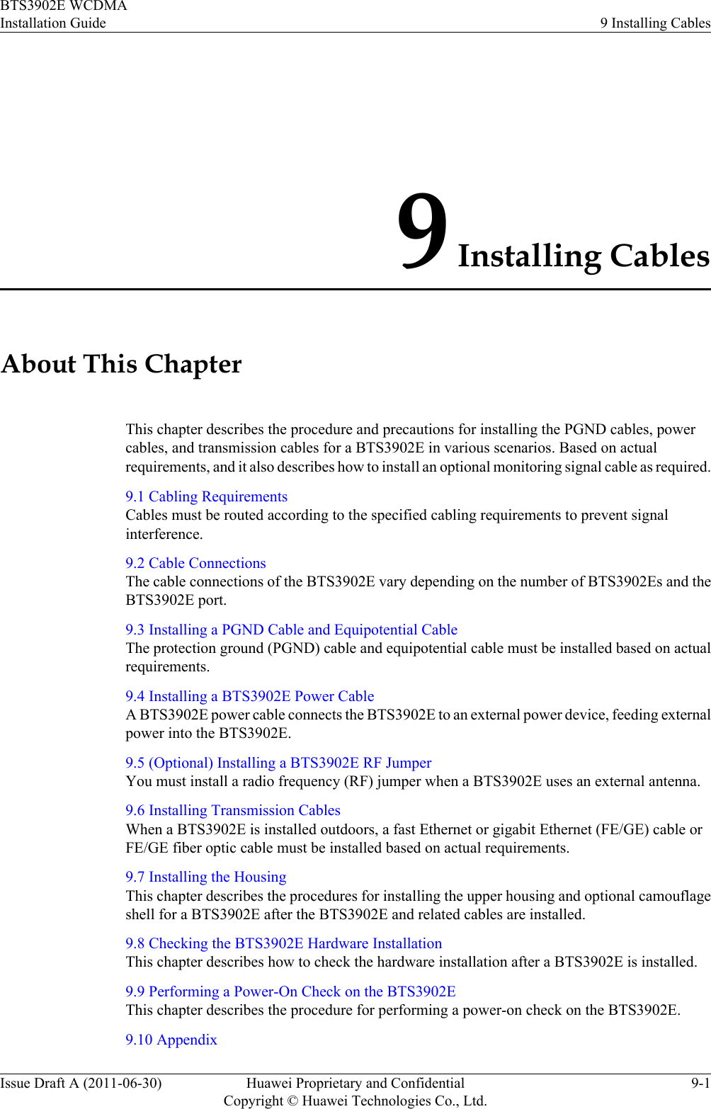
![Figure 7-13 Drilling a hole and installing an expansion bolt assembly(1) M10x80 bolt (2) Nut (3) Spring washer (4) Flat washer (5) Expansion tube 1. Use a hammer drill with a φ12 bit to drill holes perpendicularly with the wall at the markedanchor points. Ensure that the depth of each hole ranges from 55 mm to 60 mm (2.17 in.to 2.36 in.).WARNINGTake proper safety measures before drilling holes to protect your eyes and respiratory tractagainst dust.2. Use a vacuum cleaner to clear dust inside and around the holes, and then measure the inter-hole spacing. If the spacing is too wide or too narrow, drill holes again.3. Tighten each expansion bolt slightly and place them perpendicularly into each hole.4. Hit the expansion bolt using a rubber mallet to enable the expansion tube to completelyenter the hole.5. Remove the M10x80 bolt, spring washer, and flat washer from each expansion boltassembly in sequence.CAUTIONAfter disassembling an expansion bolt assembly, ensure that the top of the expansion tubeis on the same level as the wall. Otherwise, the BTS3902E cannot be installed on the wallevenly and securely.Step 4 Fit the mounting piece on the expansion bolt, and then use a combination wrench (17 mm [0.67in.]) to tighten the expansion bolt to 25 N·m (221.27 lbf·in.), as shown in Figure 7-14.BTS3902E WCDMAInstallation Guide 7 Installing a BTS3902EIssue Draft A (2011-06-30) Huawei Proprietary and ConfidentialCopyright © Huawei Technologies Co., Ltd.7-11](https://usermanual.wiki/Huawei-Technologies/BTS3902E-U1900/User-Guide-1487677-Page-53.png)
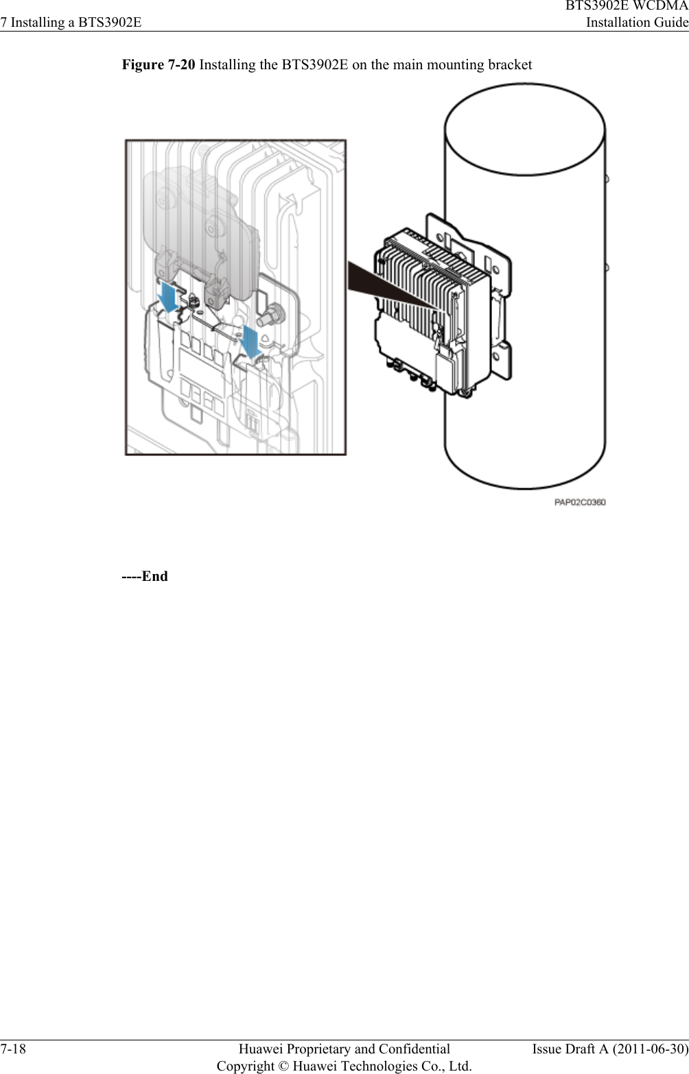
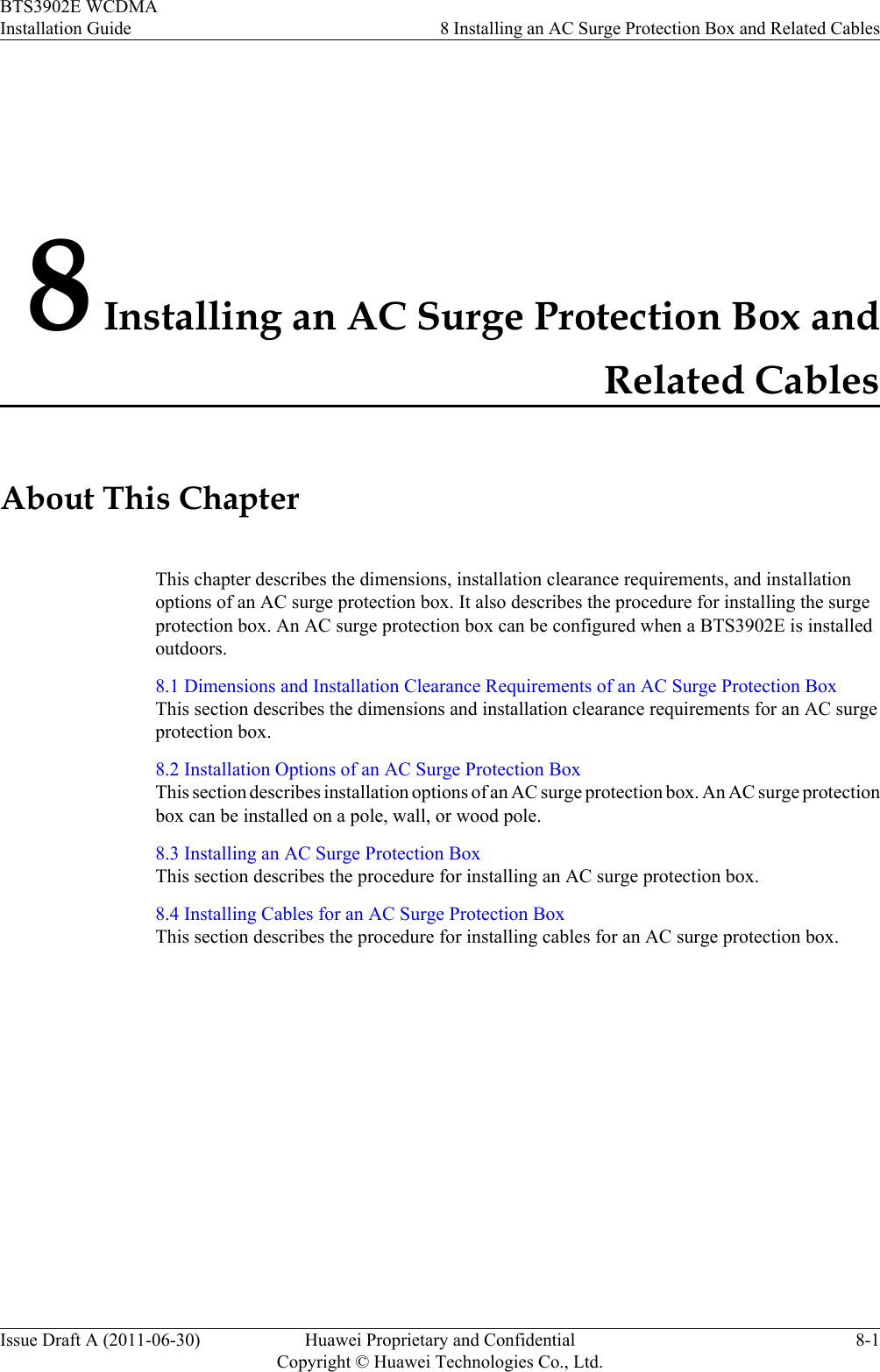


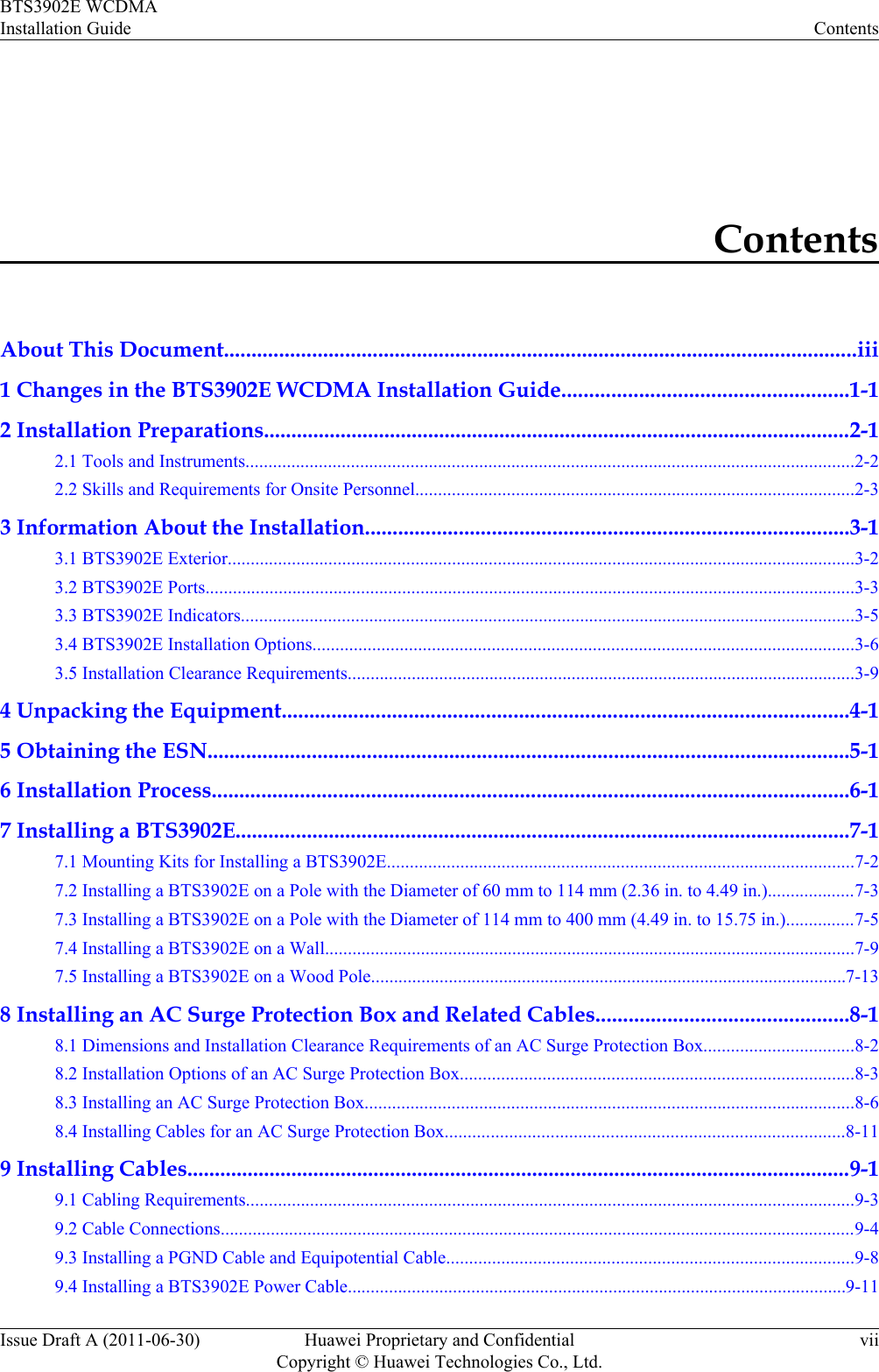
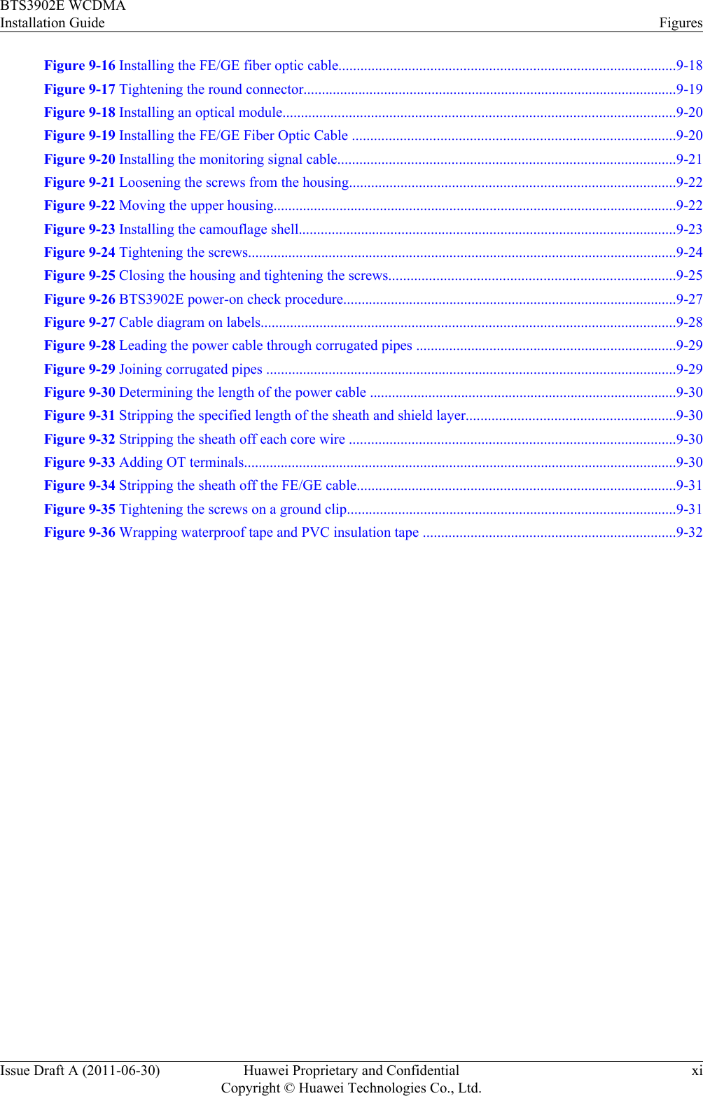
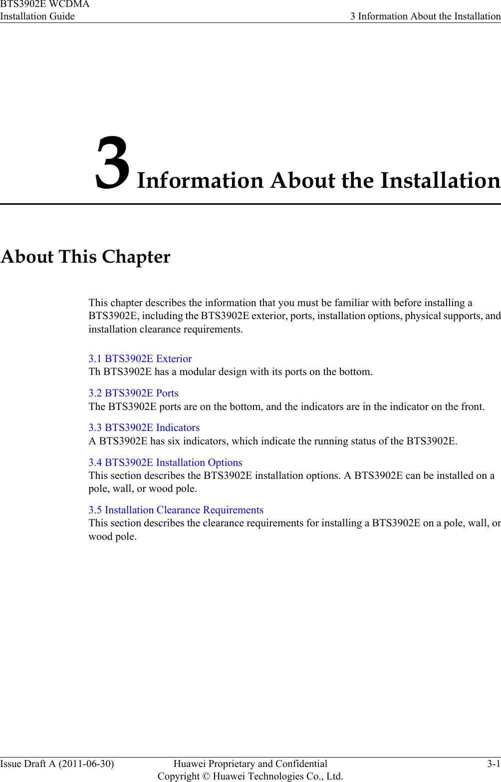
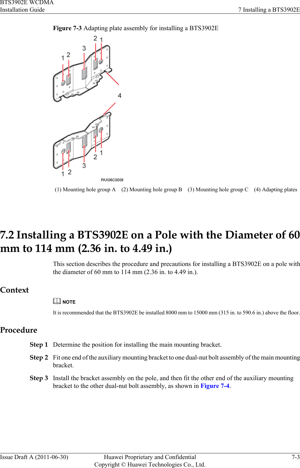
![Figure 9-4 Cable connections of two BTS3902Es implementing transmission and cascadingusing fiber optic cables(1) BTS3902E power cable (2) PGND cable (optional) (3) Equipotential cable (optional)(4) FE/GE fiber optic cable (5) BTS3902E monitoring signalcable (optional)(6) FE/GE fiber optic cable forcascading9.3 Installing a PGND Cable and Equipotential CableThe protection ground (PGND) cable and equipotential cable must be installed based on actualrequirements.ContextTable 9-1 lists the specifications of the PGND cable and equipotential cable.Table 9-1 Specifications of the BTS3902E PGND cable and equipotential cableCable One End The Other End RemarksPGND cable OT terminal (M6, 16mm2 [0.025 in.2])OT terminal (M6, 16mm2 [0.025 in.2])Green and yellow9 Installing CablesBTS3902E WCDMAInstallation Guide9-8 Huawei Proprietary and ConfidentialCopyright © Huawei Technologies Co., Ltd.Issue Draft A (2011-06-30)](https://usermanual.wiki/Huawei-Technologies/BTS3902E-U1900/User-Guide-1487677-Page-84.png)
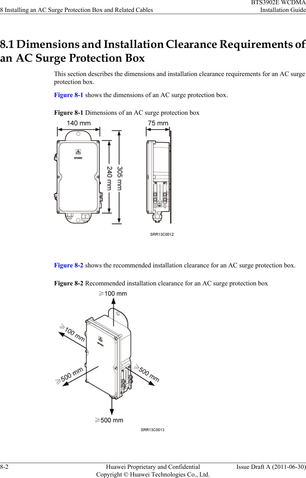
![Cable One End The Other End RemarksEquipotential cable OT terminal (M6, 16mm2 [0.025 in.2])OT terminal (M6, 16mm2 [0.025 in.2])Green and yellow ProcedurelInstall the PGND cable when no AC surge protection box is installed, as shown in Figure9-5.1. Connect one end of the BTS3902E PGND terminal to the ground cable on theBTS3902E and the other end to the external ground bar.Figure 9-5 Installing the BTS3902E PGND cableNOTEWhen installing the PGND cable, tightly press the OT terminal in the correct direction, asshown in Figure 9-6.BTS3902E WCDMAInstallation Guide 9 Installing CablesIssue Draft A (2011-06-30) Huawei Proprietary and ConfidentialCopyright © Huawei Technologies Co., Ltd.9-9](https://usermanual.wiki/Huawei-Technologies/BTS3902E-U1900/User-Guide-1487677-Page-85.png)


![Figure 9-4 Cable connections of two BTS3902Es implementing transmission and cascadingusing fiber optic cables(1) BTS3902E power cable (2) PGND cable (optional) (3) Equipotential cable (optional)(4) FE/GE fiber optic cable (5) BTS3902E monitoring signalcable (optional)(6) FE/GE fiber optic cable forcascading9.3 Installing a PGND Cable and Equipotential CableThe protection ground (PGND) cable and equipotential cable must be installed based on actualrequirements.ContextTable 9-1 lists the specifications of the PGND cable and equipotential cable.Table 9-1 Specifications of the BTS3902E PGND cable and equipotential cableCable One End The Other End RemarksPGND cable OT terminal (M6, 16mm2 [0.025 in.2])OT terminal (M6, 16mm2 [0.025 in.2])Green and yellow9 Installing CablesBTS3902E WCDMAInstallation Guide9-8 Huawei Proprietary and ConfidentialCopyright © Huawei Technologies Co., Ltd.Issue Draft A (2011-06-30)](https://usermanual.wiki/Huawei-Technologies/BTS3902E-U1900/User-Guide-1487677-Page-104.png)
![Cable One End The Other End RemarksEquipotential cable OT terminal (M6, 16mm2 [0.025 in.2])OT terminal (M6, 16mm2 [0.025 in.2])Green and yellow ProcedurelInstall the PGND cable when no AC surge protection box is installed, as shown in Figure9-5.1. Connect one end of the BTS3902E PGND terminal to the ground cable on theBTS3902E and the other end to the external ground bar.Figure 9-5 Installing the BTS3902E PGND cableNOTEWhen installing the PGND cable, tightly press the OT terminal in the correct direction, asshown in Figure 9-6.BTS3902E WCDMAInstallation Guide 9 Installing CablesIssue Draft A (2011-06-30) Huawei Proprietary and ConfidentialCopyright © Huawei Technologies Co., Ltd.9-9](https://usermanual.wiki/Huawei-Technologies/BTS3902E-U1900/User-Guide-1487677-Page-105.png)