Huawei Technologies BTS3902E-U1900 Micro BTS User Manual Installation Guide
Huawei Technologies Co.,Ltd Micro BTS Installation Guide
Installation Guide

BTS3902E WCDMA
Installation Guide
Issue Draft A
Date 2011-06-30
HUAWEI TECHNOLOGIES CO., LTD.

Copyright © Huawei Technologies Co., Ltd. 2011. All rights reserved.
No part of this document may be reproduced or transmitted in any form or by any means without prior written
consent of Huawei Technologies Co., Ltd.
Trademarks and Permissions
and other Huawei trademarks are trademarks of Huawei Technologies Co., Ltd.
All other trademarks and trade names mentioned in this document are the property of their respective holders.
Notice
The purchased products, services and features are stipulated by the contract made between Huawei and the
customer. All or part of the products, services and features described in this document may not be within the
purchase scope or the usage scope. Unless otherwise specified in the contract, all statements, information,
and recommendations in this document are provided "AS IS" without warranties, guarantees or representations
of any kind, either express or implied.
The information in this document is subject to change without notice. Every effort has been made in the
preparation of this document to ensure accuracy of the contents, but all statements, information, and
recommendations in this document do not constitute the warranty of any kind, express or implied.
Huawei Technologies Co., Ltd.
Address: Huawei Industrial Base
Bantian, Longgang
Shenzhen 518129
People's Republic of China
Website: http://www.huawei.com
Email: support@huawei.com
Issue Draft A (2011-06-30) Huawei Proprietary and Confidential
Copyright © Huawei Technologies Co., Ltd.
i
About This Document
Purpose
This document describes the procedures for installing a BTS3902E in different scenarios. It also
provides checklists for hardware installation.
Product Version
The following table lists the product version related to this document.
Product Name Product Version
BTS3902E WCDMA (referred to as
BTS3902E in this document)
V200R013
Intended Audience
This document is intended for:
lBase station installation engineers
Organization
1 Changes in the BTS3902E WCDMA Installation Guide
This chapter describes the changes in the BTS3902E WCDMA Installation Guide.
2 Installation Preparations
This chapter describes instrument preparations, and skills and qualifications that installation
engineers must possess.
3 Information About the Installation
This chapter describes the information that you must be familiar with before installing a
BTS3902E, including the BTS3902E exterior, ports, installation options, physical supports, and
installation clearance requirements.
4 Unpacking the Equipment
BTS3902E WCDMA
Installation Guide About This Document
Issue Draft A (2011-06-30) Huawei Proprietary and Confidential
Copyright © Huawei Technologies Co., Ltd.
iii
Unpack and check the delivered equipment to ensure that all the materials are included and intact.
5 Obtaining the ESN
The Electronic Serial Number (ESN) is a unique identifier of a Network Element (NE). Record
the ESN for later commissioning of the base station before installation.
6 Installation Process
The BTS3902E installation process involves installing a BTS3902E and related cables, checking
the BTS3902E hardware installation, and powering on the BTS3902E.
7 Installing a BTS3902E
This section describes the procedures for installing a BTS3902E. The BTS3902E can be installed
on a pole, wall, or wood pole depending on the installation environment.
8 Installing an AC Surge Protection Box and Related Cables
This chapter describes the dimensions, installation clearance requirements, and installation
options of an AC surge protection box. It also describes the procedure for installing the surge
protection box. An AC surge protection box can be configured when a BTS3902E is installed
outdoors.
9 Installing Cables
This chapter describes the procedure and precautions for installing the PGND cables, power
cables, and transmission cables for a BTS3902E in various scenarios. Based on actual
requirements, and it also describes how to install an optional monitoring signal cable as required.
Conventions
Symbol Conventions
The symbols that may be found in this document are defined as follows.
Symbol Description
Indicates a hazard with a high level of risk, which if not
avoided, will result in death or serious injury.
Indicates a hazard with a medium or low level of risk, which
if not avoided, could result in minor or moderate injury.
Indicates a potentially hazardous situation, which if not
avoided, could result in equipment damage, data loss,
performance degradation, or unexpected results.
Indicates a tip that may help you solve a problem or save
time.
Provides additional information to emphasize or supplement
important points of the main text.
General Conventions
About This Document
BTS3902E WCDMA
Installation Guide
iv Huawei Proprietary and Confidential
Copyright © Huawei Technologies Co., Ltd.
Issue Draft A (2011-06-30)
The general conventions that may be found in this document are defined as follows.
Convention Description
Times New Roman Normal paragraphs are in Times New Roman.
Boldface Names of files, directories, folders, and users are in
boldface. For example, log in as user root.
Italic Book titles are in italics.
Courier New Examples of information displayed on the screen are in
Courier New.
Command Conventions
The command conventions that may be found in this document are defined as follows.
Convention Description
Boldface The keywords of a command line are in boldface.
Italic Command arguments are in italics.
[ ] Items (keywords or arguments) in brackets [ ] are optional.
{ x | y | ... } Optional items are grouped in braces and separated by
vertical bars. One item is selected.
[ x | y | ... ] Optional items are grouped in brackets and separated by
vertical bars. One item is selected or no item is selected.
{ x | y | ... }*Optional items are grouped in braces and separated by
vertical bars. A minimum of one item or a maximum of all
items can be selected.
[ x | y | ... ]*Optional items are grouped in brackets and separated by
vertical bars. Several items or no item can be selected.
GUI Conventions
The GUI conventions that may be found in this document are defined as follows.
Convention Description
Boldface Buttons, menus, parameters, tabs, window, and dialog titles
are in boldface. For example, click OK.
>Multi-level menus are in boldface and separated by the ">"
signs. For example, choose File > Create > Folder.
Keyboard Operations
BTS3902E WCDMA
Installation Guide About This Document
Issue Draft A (2011-06-30) Huawei Proprietary and Confidential
Copyright © Huawei Technologies Co., Ltd.
v
The keyboard operations that may be found in this document are defined as follows.
Format Description
Key Press the key. For example, press Enter and press Tab.
Key 1+Key 2 Press the keys concurrently. For example, pressing Ctrl+Alt
+A means the three keys should be pressed concurrently.
Key 1, Key 2 Press the keys in turn. For example, pressing Alt, A means
the two keys should be pressed in turn.
Mouse Operations
The mouse operations that may be found in this document are defined as follows.
Action Description
Click Select and release the primary mouse button without moving
the pointer.
Double-click Press the primary mouse button twice continuously and
quickly without moving the pointer.
Drag Press and hold the primary mouse button and move the
pointer to a certain position.
About This Document
BTS3902E WCDMA
Installation Guide
vi Huawei Proprietary and Confidential
Copyright © Huawei Technologies Co., Ltd.
Issue Draft A (2011-06-30)

Contents
About This Document...................................................................................................................iii
1 Changes in the BTS3902E WCDMA Installation Guide....................................................1-1
2 Installation Preparations...........................................................................................................2-1
2.1 Tools and Instruments.....................................................................................................................................2-2
2.2 Skills and Requirements for Onsite Personnel................................................................................................2-3
3 Information About the Installation........................................................................................3-1
3.1 BTS3902E Exterior.........................................................................................................................................3-2
3.2 BTS3902E Ports..............................................................................................................................................3-3
3.3 BTS3902E Indicators......................................................................................................................................3-5
3.4 BTS3902E Installation Options......................................................................................................................3-6
3.5 Installation Clearance Requirements...............................................................................................................3-9
4 Unpacking the Equipment.......................................................................................................4-1
5 Obtaining the ESN.....................................................................................................................5-1
6 Installation Process....................................................................................................................6-1
7 Installing a BTS3902E................................................................................................................7-1
7.1 Mounting Kits for Installing a BTS3902E......................................................................................................7-2
7.2 Installing a BTS3902E on a Pole with the Diameter of 60 mm to 114 mm (2.36 in. to 4.49 in.)...................7-3
7.3 Installing a BTS3902E on a Pole with the Diameter of 114 mm to 400 mm (4.49 in. to 15.75 in.)...............7-5
7.4 Installing a BTS3902E on a Wall....................................................................................................................7-9
7.5 Installing a BTS3902E on a Wood Pole........................................................................................................7-13
8 Installing an AC Surge Protection Box and Related Cables..............................................8-1
8.1 Dimensions and Installation Clearance Requirements of an AC Surge Protection Box.................................8-2
8.2 Installation Options of an AC Surge Protection Box......................................................................................8-3
8.3 Installing an AC Surge Protection Box...........................................................................................................8-6
8.4 Installing Cables for an AC Surge Protection Box.......................................................................................8-11
9 Installing Cables.........................................................................................................................9-1
9.1 Cabling Requirements.....................................................................................................................................9-3
9.2 Cable Connections...........................................................................................................................................9-4
9.3 Installing a PGND Cable and Equipotential Cable.........................................................................................9-8
9.4 Installing a BTS3902E Power Cable.............................................................................................................9-11
BTS3902E WCDMA
Installation Guide Contents
Issue Draft A (2011-06-30) Huawei Proprietary and Confidential
Copyright © Huawei Technologies Co., Ltd.
vii

9.5 (Optional) Installing a BTS3902E RF Jumper..............................................................................................9-13
9.6 Installing Transmission Cables.....................................................................................................................9-16
9.6.1 Installing an FE/GE Cable....................................................................................................................9-16
9.6.2 Installing an FE/GE Fiber Optic Cable................................................................................................9-17
9.6.3 Installing an FE/GE Fiber Optic Cable for Cascading.........................................................................9-19
9.6.4 (Optional) Installing the Monitoring Signal Cable..............................................................................9-20
9.7 Installing the Housing...................................................................................................................................9-21
9.7.1 (Optional) Installing a Camouflage Shell.............................................................................................9-21
9.7.2 Installing the Upper Housing...............................................................................................................9-24
9.8 Checking the BTS3902E Hardware Installation...........................................................................................9-25
9.9 Performing a Power-On Check on the BTS3902E........................................................................................9-27
9.10 Appendix.....................................................................................................................................................9-28
9.10.1 Adding OT Terminals to the Power Cable Connected to the AC Surge Protection Box...................9-28
9.10.2 Installing a Ground Clip.....................................................................................................................9-30
Contents
BTS3902E WCDMA
Installation Guide
viii Huawei Proprietary and Confidential
Copyright © Huawei Technologies Co., Ltd.
Issue Draft A (2011-06-30)

Figures
Figure 3-1 BTS3902E.......................................................................................................................................... 3-2
Figure 3-2 Dimensions of a BTS3902E without a housing..................................................................................3-2
Figure 3-3 Dimensions of a BTS3902E with a housing and antennas.................................................................3-3
Figure 3-4 Positions of the BTS3902E ports and indicators................................................................................3-4
Figure 3-5 Diameter of a pole.............................................................................................................................. 3-7
Figure 3-6 BTS3902E installed on a pole............................................................................................................3-7
Figure 3-7 Diameter of a pole.............................................................................................................................. 3-7
Figure 3-8 BTS3902E installed on a pole............................................................................................................3-8
Figure 3-9 BTS3902E installed on a wall............................................................................................................3-9
Figure 3-10 BTS3902E installed on a wood pole................................................................................................ 3-9
Figure 3-11 Recommended installation clearance for a single BTS3902E........................................................3-10
Figure 3-12 Minimum installation clearance for a single BTS3902E................................................................3-10
Figure 3-13 Recommended installation clearance for two BTS3902Es installed side by side..........................3-11
Figure 3-14 Minimum installation clearance for two BTS3902Es installed side by side..................................3-11
Figure 3-15 Recommended installation clearance for two BTS3902Es installed in a vertical line...................3-12
Figure 3-16 Minimum installation clearance for two BTS3902Es installed in a vertical line...........................3-13
Figure 5-1 Obtaining the ESN..............................................................................................................................5-2
Figure 6-1 Process of installing the BTS3902E...................................................................................................6-2
Figure 7-1 Rear of a BTS3902E...........................................................................................................................7-2
Figure 7-2 Mounting bracket assembly for installing a BTS3902E.....................................................................7-2
Figure 7-3 Adapting plate assembly for installing a BTS3902E..........................................................................7-3
Figure 7-4 Installing the bracket assembly...........................................................................................................7-4
Figure 7-5 Securing the bracket assembly onto the pole......................................................................................7-4
Figure 7-6 Installing the BTS3902E on the main mounting bracket................................................................... 7-5
Figure 7-7 Installing the adapting plate assembly ...............................................................................................7-6
Figure 7-8 Installing the hose clamps...................................................................................................................7-7
Figure 7-9 Securing the hose clamp.....................................................................................................................7-8
Figure 7-10 Installing the BTS3902E on the main mounting bracket................................................................. 7-8
Figure 7-11 Installing the adapting plate assembly .............................................................................................7-9
Figure 7-12 Marking the anchor points..............................................................................................................7-10
Figure 7-13 Drilling a hole and installing an expansion bolt assembly.............................................................7-11
Figure 7-14 Fitting the mounting piece on the expansion bolt...........................................................................7-12
Figure 7-15 Installing the BTS3902E on the main mounting bracket...............................................................7-13
BTS3902E WCDMA
Installation Guide Figures
Issue Draft A (2011-06-30) Huawei Proprietary and Confidential
Copyright © Huawei Technologies Co., Ltd.
ix

Figure 7-16 Drilling holes..................................................................................................................................7-14
Figure 7-17 Installing the adapting plate assembly ...........................................................................................7-15
Figure 7-18 Securing the securing pieces...........................................................................................................7-16
Figure 7-19 Tightening nuts...............................................................................................................................7-17
Figure 7-20 Installing the BTS3902E on the main mounting bracket...............................................................7-18
Figure 8-1 Dimensions of an AC surge protection box........................................................................................8-2
Figure 8-2 Recommended installation clearance for an AC surge protection box...............................................8-2
Figure 8-3 Minimum installation clearance for an AC surge protection box.......................................................8-3
Figure 8-4 Diameter of a pole..............................................................................................................................8-3
Figure 8-5 AC surge protection box installed on a pole.......................................................................................8-4
Figure 8-6 Diameter of a pole..............................................................................................................................8-4
Figure 8-7 AC surge protection box installed on a pole.......................................................................................8-5
Figure 8-8 AC surge protection box installed on a wall.......................................................................................8-5
Figure 8-9 AC surge protection box installed on a wood pole.............................................................................8-6
Figure 8-10 Installing the AC surge protection box on a pole.............................................................................8-6
Figure 8-11 Marking the anchor points................................................................................................................8-7
Figure 8-12 Installing an expansion bolt..............................................................................................................8-8
Figure 8-13 Installing an AC surge protection box..............................................................................................8-8
Figure 8-14 Drilling holes....................................................................................................................................8-9
Figure 8-15 Installing the AC surge protection box on the wood pole..............................................................8-10
Figure 8-16 Tightening the nuts.........................................................................................................................8-11
Figure 8-17 Opening the cover plate of the AC surge protection box...............................................................8-12
Figure 8-18 Cable connections of the AC surge protection box........................................................................8-12
Figure 8-19 Closing the cover plate of the AC surge protection box.................................................................8-13
Figure 8-20 Securing AC power cables.............................................................................................................8-14
Figure 8-21 Installing the PGND cable and equipotential cable........................................................................8-14
Figure 9-1 Cable connections of a single BTS3902E implementing transmission over an electrical port..........9-5
Figure 9-2 Cable connections of a single BTS3902E implementing transmission over an optical port..............9-6
Figure 9-3 Cable connections of a single BTS3902E implementing POE over an electrical port and transmission
using a fiber optic cable........................................................................................................................................9-7
Figure 9-4 Cable connections of two BTS3902Es implementing transmission and cascading using fiber optic cables
...............................................................................................................................................................................9-8
Figure 9-5 Installing the BTS3902E PGND cable...............................................................................................9-9
Figure 9-6 Installing an OT terminal in the correct manner...............................................................................9-10
Figure 9-7 Installing the PGND cable and equipotential cable..........................................................................9-10
Figure 9-8 Installing an OT terminal in the correct manner...............................................................................9-11
Figure 9-9 Connection of the power cable between the BTS3902E and power equipment...............................9-12
Figure 9-10 Connection of the BTS3902E power cable to the surge protection box.........................................9-13
Figure 9-11 Installing the BTS3902E RF jumper..............................................................................................9-14
Figure 9-12 Wrap the connector of the BTS3902E RF jumper..........................................................................9-14
Figure 9-13 Waterproofing a dustproof cap.......................................................................................................9-15
Figure 9-14 Installing the FE/GE cable .............................................................................................................9-17
Figure 9-15 Installing the optical module..........................................................................................................9-18
Figures
BTS3902E WCDMA
Installation Guide
x Huawei Proprietary and Confidential
Copyright © Huawei Technologies Co., Ltd.
Issue Draft A (2011-06-30)

Figure 9-16 Installing the FE/GE fiber optic cable............................................................................................9-18
Figure 9-17 Tightening the round connector......................................................................................................9-19
Figure 9-18 Installing an optical module...........................................................................................................9-20
Figure 9-19 Installing the FE/GE Fiber Optic Cable ........................................................................................9-20
Figure 9-20 Installing the monitoring signal cable............................................................................................9-21
Figure 9-21 Loosening the screws from the housing.........................................................................................9-22
Figure 9-22 Moving the upper housing..............................................................................................................9-22
Figure 9-23 Installing the camouflage shell.......................................................................................................9-23
Figure 9-24 Tightening the screws.....................................................................................................................9-24
Figure 9-25 Closing the housing and tightening the screws..............................................................................9-25
Figure 9-26 BTS3902E power-on check procedure...........................................................................................9-27
Figure 9-27 Cable diagram on labels.................................................................................................................9-28
Figure 9-28 Leading the power cable through corrugated pipes .......................................................................9-29
Figure 9-29 Joining corrugated pipes ................................................................................................................9-29
Figure 9-30 Determining the length of the power cable ....................................................................................9-30
Figure 9-31 Stripping the specified length of the sheath and shield layer.........................................................9-30
Figure 9-32 Stripping the sheath off each core wire .........................................................................................9-30
Figure 9-33 Adding OT terminals......................................................................................................................9-30
Figure 9-34 Stripping the sheath off the FE/GE cable.......................................................................................9-31
Figure 9-35 Tightening the screws on a ground clip..........................................................................................9-31
Figure 9-36 Wrapping waterproof tape and PVC insulation tape .....................................................................9-32
BTS3902E WCDMA
Installation Guide Figures
Issue Draft A (2011-06-30) Huawei Proprietary and Confidential
Copyright © Huawei Technologies Co., Ltd.
xi

Tables
Table 3-1 BTS3902E ports and indicators...........................................................................................................3-4
Table 3-2 BTS3902E indicators...........................................................................................................................3-5
Table 9-1 Specifications of the BTS3902E PGND cable and equipotential cable...............................................9-8
Table 9-2 Specifications of the BTS3902E power cable....................................................................................9-11
Table 9-3 Checklist for the BTS3902E Hardware Installation...........................................................................9-25
Table 9-4 Checklist for the installation of an AC surge protection box.............................................................9-26
BTS3902E WCDMA
Installation Guide Tables
Issue Draft A (2011-06-30) Huawei Proprietary and Confidential
Copyright © Huawei Technologies Co., Ltd.
xiii

1 Changes in the BTS3902E WCDMA
Installation Guide
This chapter describes the changes in the BTS3902E WCDMA Installation Guide.
Draft A (2011-06-30)
This is the draft.
BTS3902E WCDMA
Installation Guide 1 Changes in the BTS3902E WCDMA Installation Guide
Issue Draft A (2011-06-30) Huawei Proprietary and Confidential
Copyright © Huawei Technologies Co., Ltd.
1-1

2 Installation Preparations
About This Chapter
This chapter describes instrument preparations, and skills and qualifications that installation
engineers must possess.
2.1 Tools and Instruments
All required tools and instruments must be ready before the installation.
2.2 Skills and Requirements for Onsite Personnel
Onsite personnel must be qualified and trained. Before performing any operation, onsite
personnel must be familiar with correct operation methods and safety precautions.
BTS3902E WCDMA
Installation Guide 2 Installation Preparations
Issue Draft A (2011-06-30) Huawei Proprietary and Confidential
Copyright © Huawei Technologies Co., Ltd.
2-1
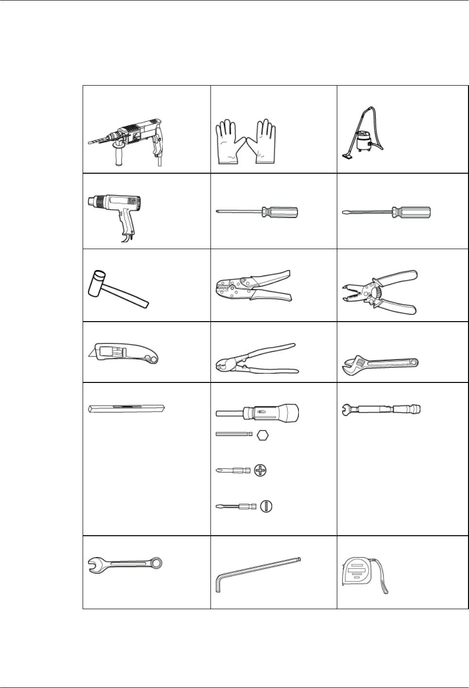
2.1 Tools and Instruments
All required tools and instruments must be ready before the installation.
Hammer drill (with a φ 12
bit, φ 14 bit, and φ 18 bit)
Electrostatic discharge
(ESD) gloves
Vacuum cleaner
Heat gun Phillips screwdriver (M3 to
M6)
Flat-head screwdriver (M3 to
M6)
Rubber mallet COAX crimping tool Wire stripper
Utility knife Wire clippers Adjustable wrench (capacity
≥ 32 mm [1.26 in.])
Level Torque screwdriver
5 mm (0.2 in.)
(M3 to M6)
(M3 to M6)
Torque wrench
Capacity: 17 mm (0.67 in.) or
21 mm (0.83 in.)
Combination wrench
Capacity: 17 mm [0.67 in.] or
21 mm [0.83 in.]
Inner hexagon wrench Measuring tape
2 Installation Preparations
BTS3902E WCDMA
Installation Guide
2-2 Huawei Proprietary and Confidential
Copyright © Huawei Technologies Co., Ltd.
Issue Draft A (2011-06-30)

Multimeter Marker (diameter ≤ 10 mm
[0.39 in.])
—
2.2 Skills and Requirements for Onsite Personnel
Onsite personnel must be qualified and trained. Before performing any operation, onsite
personnel must be familiar with correct operation methods and safety precautions.
Before the installation, pay attention to the following items:
lThe customer's technical engineers must be trained by Huawei and be familiar with the
proper installation and operation methods.
lThe number of onsite personnel depends on the engineering schedule and installation
environment. Generally, only three to five onsite personnel are necessary.
BTS3902E WCDMA
Installation Guide 2 Installation Preparations
Issue Draft A (2011-06-30) Huawei Proprietary and Confidential
Copyright © Huawei Technologies Co., Ltd.
2-3

3 Information About the Installation
About This Chapter
This chapter describes the information that you must be familiar with before installing a
BTS3902E, including the BTS3902E exterior, ports, installation options, physical supports, and
installation clearance requirements.
3.1 BTS3902E Exterior
Th BTS3902E has a modular design with its ports on the bottom.
3.2 BTS3902E Ports
The BTS3902E ports are on the bottom, and the indicators are in the indicator on the front.
3.3 BTS3902E Indicators
A BTS3902E has six indicators, which indicate the running status of the BTS3902E.
3.4 BTS3902E Installation Options
This section describes the BTS3902E installation options. A BTS3902E can be installed on a
pole, wall, or wood pole.
3.5 Installation Clearance Requirements
This section describes the clearance requirements for installing a BTS3902E on a pole, wall, or
wood pole.
BTS3902E WCDMA
Installation Guide 3 Information About the Installation
Issue Draft A (2011-06-30) Huawei Proprietary and Confidential
Copyright © Huawei Technologies Co., Ltd.
3-1
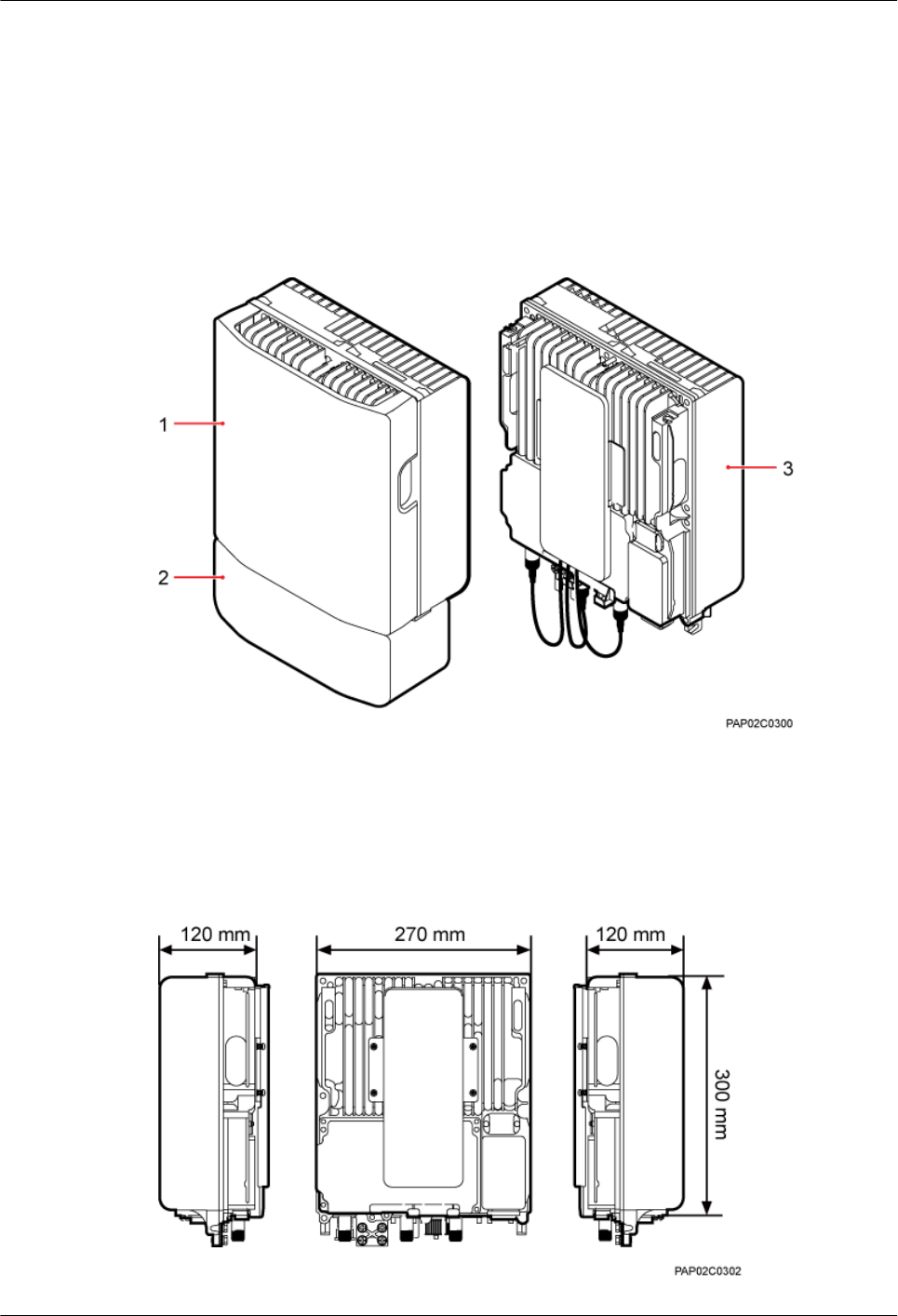
3.1 BTS3902E Exterior
Th BTS3902E has a modular design with its ports on the bottom.
Figure 3-1 shows the BTS3902E. The BTS3902E on the left has a housing, and the BTS3902E
on the right does not have a housing. The camouflage shell is optional.
Figure 3-1 BTS3902E
(1) Upper housing (2) Camouflage shell (3) BTS3902E
Figure 3-2 shows the dimensions of a BTS3902E without a housing, and Figure 3-3shows the
dimensions of a BTS3902E with a housing.
Figure 3-2 Dimensions of a BTS3902E without a housing
3 Information About the Installation
BTS3902E WCDMA
Installation Guide
3-2 Huawei Proprietary and Confidential
Copyright © Huawei Technologies Co., Ltd.
Issue Draft A (2011-06-30)
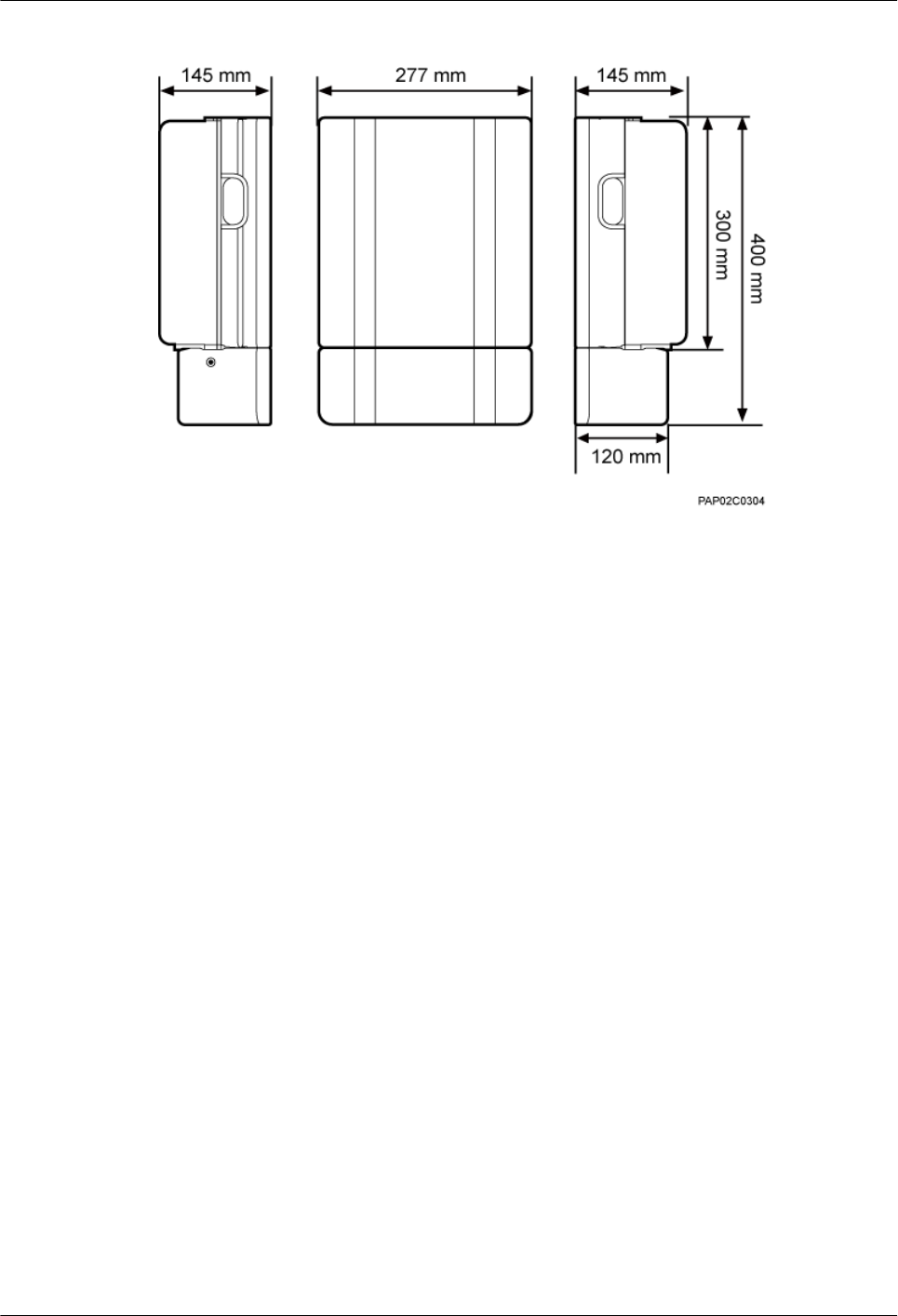
Figure 3-3 Dimensions of a BTS3902E with a housing and antennas
3.2 BTS3902E Ports
The BTS3902E ports are on the bottom, and the indicators are in the indicator on the front.
Figure 3-4 shows the positions of the BTS3902E ports and indicators.
BTS3902E WCDMA
Installation Guide 3 Information About the Installation
Issue Draft A (2011-06-30) Huawei Proprietary and Confidential
Copyright © Huawei Technologies Co., Ltd.
3-3
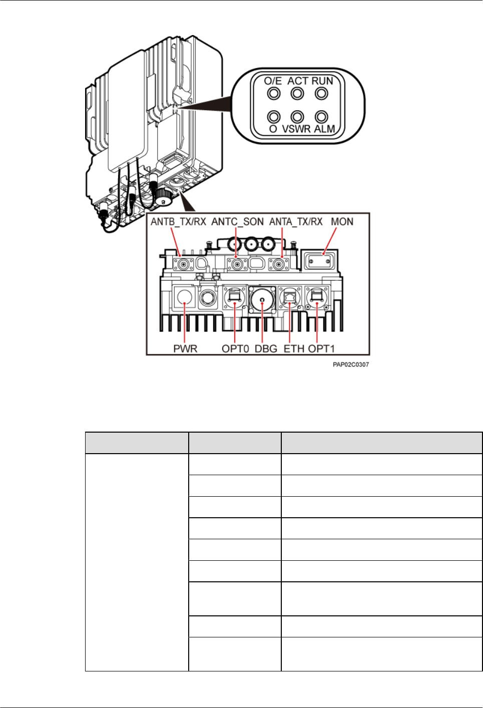
Figure 3-4 Positions of the BTS3902E ports and indicators
Table 3-1 describes the BTS3902E ports and indicators.
Table 3-1 BTS3902E ports and indicators
Item Label Description
Ports ANTA_TX/RX TX/RX port A
ANTB_TX/RX TX/RX port B
ANTC_SON SON antenna port
ETH FE/GE electrical port
OPT0 FE/GE optical port
OPT1 FE/GE optical port
MON Environment monitoring port for an RS485
input and four dry contact inputs.
PWR Power supply port
DBG Port for commissioning, clock test, or
software upgrade
3 Information About the Installation
BTS3902E WCDMA
Installation Guide
3-4 Huawei Proprietary and Confidential
Copyright © Huawei Technologies Co., Ltd.
Issue Draft A (2011-06-30)
Item Label Description
Indicators RUN For details, see BTS3902E Indicators.
ALM
ACT
VSWR
O/E
O
3.3 BTS3902E Indicators
A BTS3902E has six indicators, which indicate the running status of the BTS3902E.
For details about the indicator positions on the BTS3902E panel, see BTS3902E Ports.
Table 3-2 describes BTS3902E indicators.
Table 3-2 BTS3902E indicators
Indicator Color Status Description
RUN Green Steady on There is power supply, but the BTS3902E is
faulty.
Off There is no power supply, or the BTS3902E
is faulty.
Blinking (on for
1s and off for 1s)
The BTS3902E is working properly.
Blinking (on for
0.125s and off for
0.125s)
Software is being loaded to the BTS3902E,
or the BTS3902E is not started.
ALM Red Steady on Alarms are generated, and the BTS3902E
must be replaced.
Blinking (on for
1s and off for 1s)
Alarms are generated. The alarms may be
caused by the faults on the related boards or
ports. Therefore, the necessity for
BTS3902E replacement is uncertain.
Off No alarm is generated.
ACT Green Steady on The BTS3902E is working properly with TX
channels enabled.
Blinking (on for
1s and off for 1s)
The BTS3902E is working properly with TX
channels disabled.
BTS3902E WCDMA
Installation Guide 3 Information About the Installation
Issue Draft A (2011-06-30) Huawei Proprietary and Confidential
Copyright © Huawei Technologies Co., Ltd.
3-5
Indicator Color Status Description
VSWR Red Off No VSWR alarm is generated.
Blinking red (on
for 1s and off for
1s)
VSWR alarms are generated on the
ANTB_TX/RX port.
Steady red VSWR alarms are generated on the
ANTA_TX/RX port.
Blinking red (on
for 0.125s and off
for 0.125s)
VSWR alarms are generated on the
ANTA_TX/RX and ANTB_TX/RX ports.
O/E Green Steady on The OPT1 or ETH port is connected
properly.
Blinking (on for
0.125s and off for
0.125s)
The OPT1 or ETH port is transmitting or
receiving data.
Off The OPT1 or ETH port is connected
improperly.
O Green Steady on The OPT0 port is connected properly.
Blinking (on for
0.125s and off for
0.125s)
The OPT0 port is transmitting or receiving
data.
Off The OPT0 port is connected improperly.
3.4 BTS3902E Installation Options
This section describes the BTS3902E installation options. A BTS3902E can be installed on a
pole, wall, or wood pole.
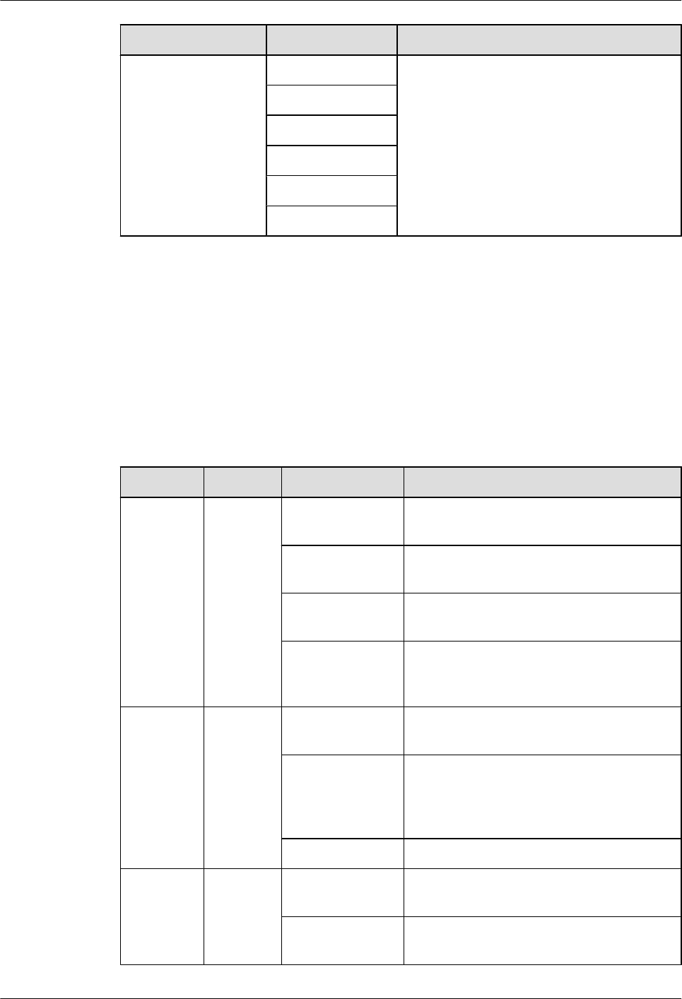
Installing a BTS3902E on a Pole with the Diameter of 60 mm to 114 mm (2.36 in. to
4.49 in.)
Figure 3-5 shows the diameter of a pole for installing a BTS3902E.
CAUTION
lThe recommended diameter is 80 mm (3.15 in.).
3 Information About the Installation
BTS3902E WCDMA
Installation Guide
3-6 Huawei Proprietary and Confidential
Copyright © Huawei Technologies Co., Ltd.
Issue Draft A (2011-06-30)
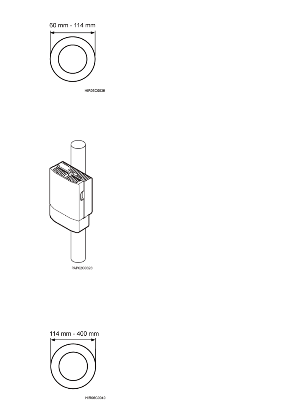
Figure 3-5 Diameter of a pole
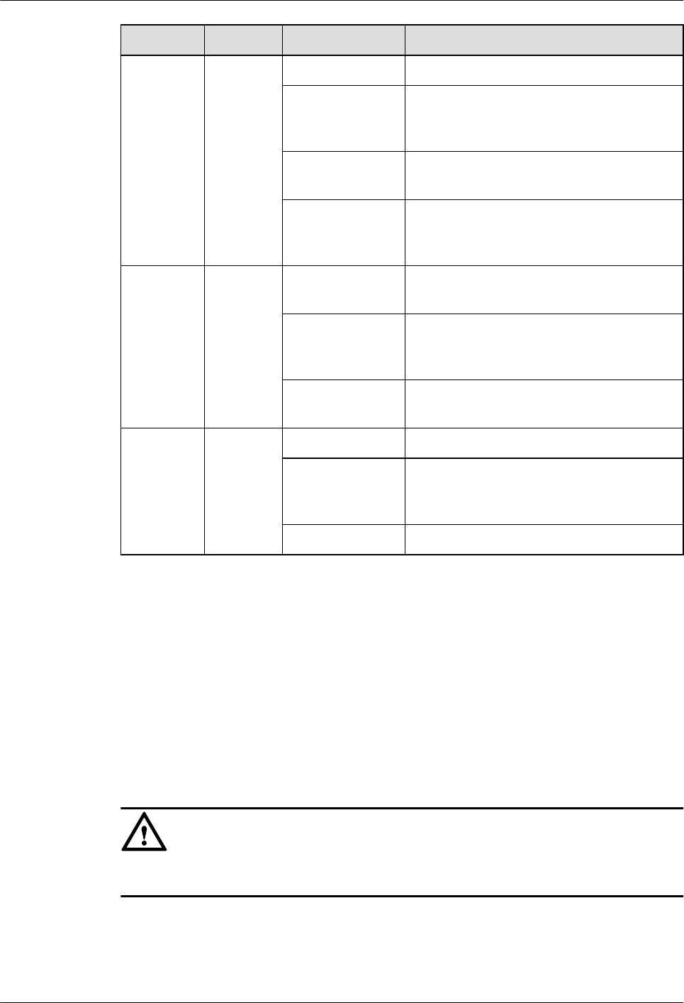
Figure 3-6 shows a BTS3902E installed on a pole.
Figure 3-6 BTS3902E installed on a pole
Installing a BTS3902E on a Pole with the Diameter of 114 mm to 400 mm (4.49 in.
to 15.75 in.)
Figure 3-7 shows the diameter of a pole for installing a BTS3902E.
Figure 3-7 Diameter of a pole
BTS3902E WCDMA
Installation Guide 3 Information About the Installation
Issue Draft A (2011-06-30) Huawei Proprietary and Confidential
Copyright © Huawei Technologies Co., Ltd.
3-7
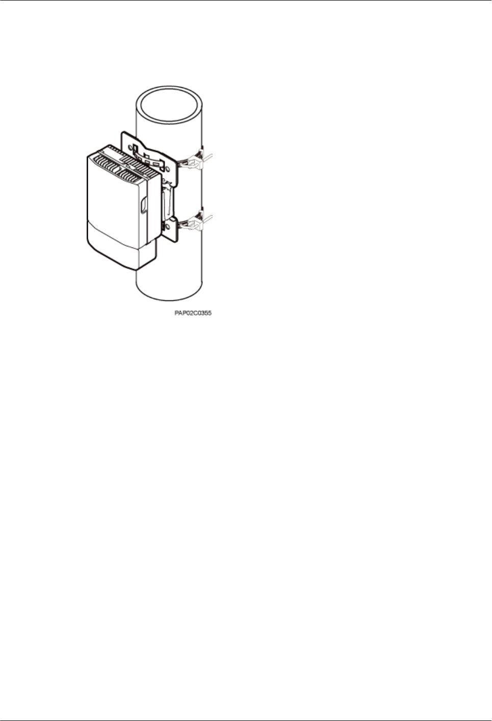
Figure 3-8 shows a BTS3902E installed on a pole.
Figure 3-8 BTS3902E installed on a pole
Installing a BTS3902E on a Wall
The wall on a BTS3902E is installed must meet the following requirements:
lWhen a single BTS3902E is installed, the wall has a capacity of bearing at least four times
the weight of the BTS3902E.
lExpansion bolts must be tightened to 30 N·m (265.52 lbf·in.) to ensure the bolts work
properly and the wall remains intact without cracks in it.
Figure 3-9 shows a BTS3902E installed on a wall.
3 Information About the Installation
BTS3902E WCDMA
Installation Guide
3-8 Huawei Proprietary and Confidential
Copyright © Huawei Technologies Co., Ltd.
Issue Draft A (2011-06-30)
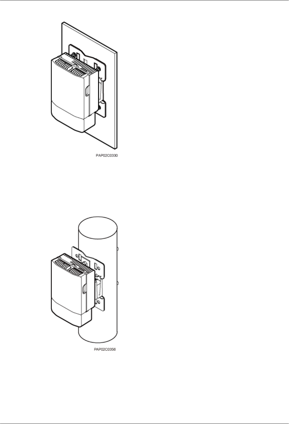
Figure 3-9 BTS3902E installed on a wall
Installing a BTS3902E on a Wood Pole
Figure 3-10 shows a BTS3902E installed on a wood pole.
Figure 3-10 BTS3902E installed on a wood pole
3.5 Installation Clearance Requirements
This section describes the clearance requirements for installing a BTS3902E on a pole, wall, or
wood pole.
Figure 3-11 shows the recommended installation clearance for a single BTS3902E.
BTS3902E WCDMA
Installation Guide 3 Information About the Installation
Issue Draft A (2011-06-30) Huawei Proprietary and Confidential
Copyright © Huawei Technologies Co., Ltd.
3-9
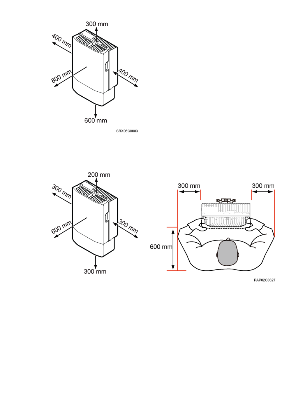
Figure 3-11 Recommended installation clearance for a single BTS3902E
Figure 3-12 shows the minimum installation clearance for a single BTS3902E.
Figure 3-12 Minimum installation clearance for a single BTS3902E
Figure 3-13 shows the recommended installation clearance for two BTS3902Es installed side
by side.
3 Information About the Installation
BTS3902E WCDMA
Installation Guide
3-10 Huawei Proprietary and Confidential
Copyright © Huawei Technologies Co., Ltd.
Issue Draft A (2011-06-30)
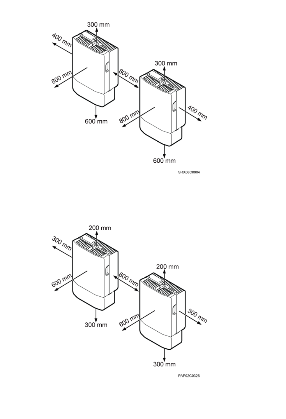
Figure 3-13 Recommended installation clearance for two BTS3902Es installed side by side
Figure 3-14 shows the minimum installation clearance for two BTS3902Es installed side by
side.
Figure 3-14 Minimum installation clearance for two BTS3902Es installed side by side
Figure 3-15 shows the recommended installation clearance for two BTS3902Es installed in a
vertical line.
BTS3902E WCDMA
Installation Guide 3 Information About the Installation
Issue Draft A (2011-06-30) Huawei Proprietary and Confidential
Copyright © Huawei Technologies Co., Ltd.
3-11

Figure 3-15 Recommended installation clearance for two BTS3902Es installed in a vertical line
(1) Pole (2) Wall
Figure 3-16 shows the minimum installation clearance for two BTS3902Es installed in a vertical
line.
3 Information About the Installation
BTS3902E WCDMA
Installation Guide
3-12 Huawei Proprietary and Confidential
Copyright © Huawei Technologies Co., Ltd.
Issue Draft A (2011-06-30)
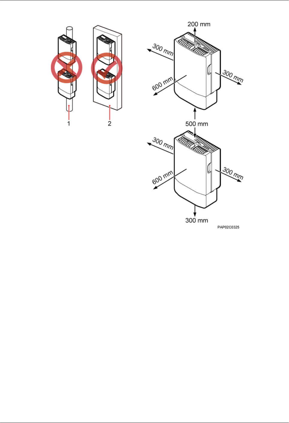
Figure 3-16 Minimum installation clearance for two BTS3902Es installed in a vertical line
(1) Pole (2) Wall
BTS3902E WCDMA
Installation Guide 3 Information About the Installation
Issue Draft A (2011-06-30) Huawei Proprietary and Confidential
Copyright © Huawei Technologies Co., Ltd.
3-13
4 Unpacking the Equipment
Unpack and check the delivered equipment to ensure that all the materials are included and intact.
Context
NOTE
When transporting, moving, or installing the equipment, components, or parts, you must:
lPrevent them from colliding with doors, walls, shelves, or other objects.
lWear clean gloves, and avoid touching the equipment, components, or parts with bare hands, sweat-
soaked gloves, or dirty gloves.
Procedure
Step 1 Check the total number of articles in each case according to the packing list.
If ... Then ...
The total number tallies with the packing
list
Go to Step 2.
The total number does not tally with the
packing list
Find out the cause and report any missing
articles to the local Huawei office.
Step 2 Check the exterior of the packing case.
If ... Then ...
The outer packing is intact Go to Step 3.
The outer packing is severely damaged or
soaked
Find out the cause and report it to the local
Huawei office.
Step 3 Check the type and quantity of the equipment in the cases according to the packing list.
BTS3902E WCDMA
Installation Guide 4 Unpacking the Equipment
Issue Draft A (2011-06-30) Huawei Proprietary and Confidential
Copyright © Huawei Technologies Co., Ltd.
4-1
If ... Then ...
Types and quantity of the article tally with
those on the packing list
Sign the Packing List with the customer.
There is any shipment shortage or wrong
shipment
Fill in and submit the Cargo Shortage and
Mishandling Report.
Articles are damaged. Fill in and submit the Article Replacement
Report.
WARNING
To protect the equipment and prevent damage to the equipment, you are advised to keep the
unpacked equipment and packing materials indoors, take photos of the stocking environment,
packing case or carton, packing materials, and any rusted or eroded equipment, and then file the
photos.
----End
4 Unpacking the Equipment
BTS3902E WCDMA
Installation Guide
4-2 Huawei Proprietary and Confidential
Copyright © Huawei Technologies Co., Ltd.
Issue Draft A (2011-06-30)

5 Obtaining the ESN
The Electronic Serial Number (ESN) is a unique identifier of a Network Element (NE). Record
the ESN for later commissioning of the base station before installation.
Procedure
Step 1 Use an M4 Phillips screwdriver to loosen the two captive screws on the housing, and then move
the upper housing until it is stopped.
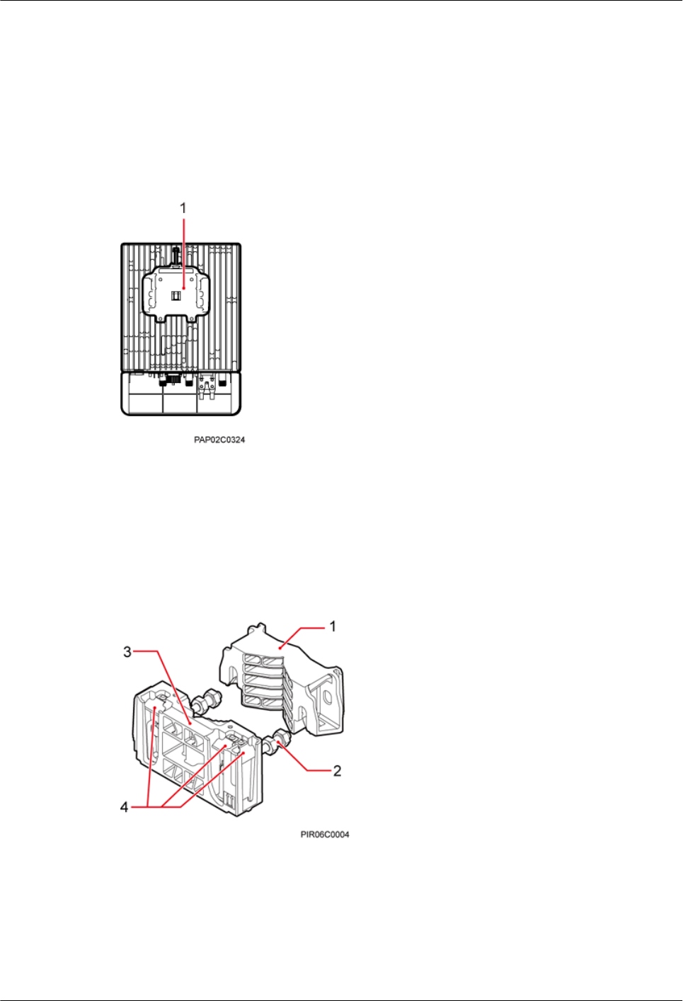
Step 2 Record the ESN on the BTS3902E.
lThe ESN is printed on the label and BTS3902E. You must remove the label to record the
site information on the side labeled Site on the label, as shown in Figure 5-1.
BTS3902E WCDMA
Installation Guide 5 Obtaining the ESN
Issue Draft A (2011-06-30) Huawei Proprietary and Confidential
Copyright © Huawei Technologies Co., Ltd.
5-1
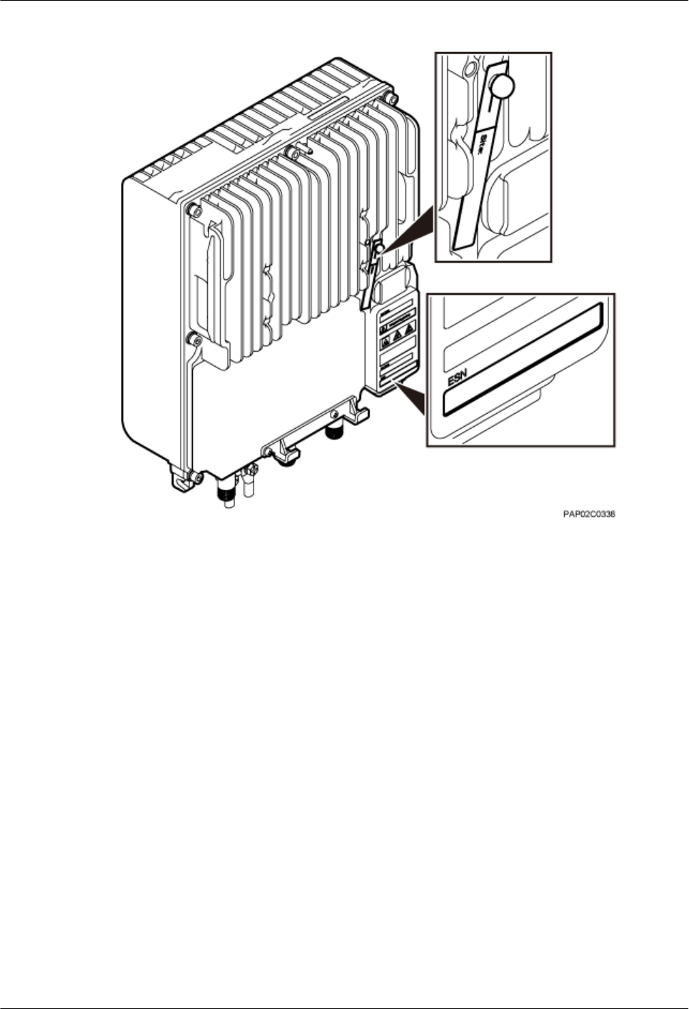
Figure 5-1 Obtaining the ESN
Step 3 Report the ESN to the engineer for the commissioning of the base station.
----End
5 Obtaining the ESN
BTS3902E WCDMA
Installation Guide
5-2 Huawei Proprietary and Confidential
Copyright © Huawei Technologies Co., Ltd.
Issue Draft A (2011-06-30)

6 Installation Process
The BTS3902E installation process involves installing a BTS3902E and related cables, checking
the BTS3902E hardware installation, and powering on the BTS3902E.
Figure 6-1 shows the process of installing a BTS3902E.
BTS3902E WCDMA
Installation Guide 6 Installation Process
Issue Draft A (2011-06-30) Huawei Proprietary and Confidential
Copyright © Huawei Technologies Co., Ltd.
6-1
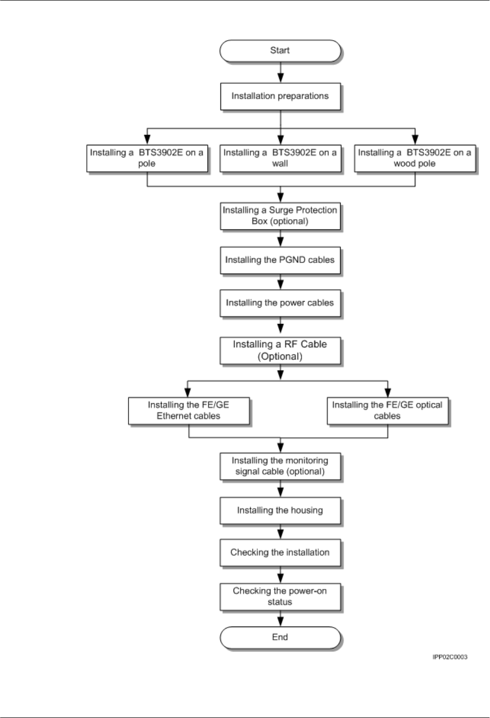
Figure 6-1 Process of installing the BTS3902E
6 Installation Process
BTS3902E WCDMA
Installation Guide
6-2 Huawei Proprietary and Confidential
Copyright © Huawei Technologies Co., Ltd.
Issue Draft A (2011-06-30)

7 Installing a BTS3902E
About This Chapter
This section describes the procedures for installing a BTS3902E. The BTS3902E can be installed
on a pole, wall, or wood pole depending on the installation environment.
7.1 Mounting Kits for Installing a BTS3902E
This section describes the brackets and attachment plate for installing a BTS3902E.
7.2 Installing a BTS3902E on a Pole with the Diameter of 60 mm to 114 mm (2.36 in. to 4.49
in.)
This section describes the procedure and precautions for installing a BTS3902E on a pole with
the diameter of 60 mm to 114 mm (2.36 in. to 4.49 in.).
7.3 Installing a BTS3902E on a Pole with the Diameter of 114 mm to 400 mm (4.49 in. to 15.75
in.)
This section describes the procedure and precautions for installing a BTS3902E on a pole with
the diameter of 114 mm to 400 mm (4.49 in. to 15.75 in.).
7.4 Installing a BTS3902E on a Wall
This section describes the procedure and precautions for installing a BTS3902E on a wall.
7.5 Installing a BTS3902E on a Wood Pole
This section describes the procedure and precautions for installing a BTS3902E on a wood pole.
BTS3902E WCDMA
Installation Guide 7 Installing a BTS3902E
Issue Draft A (2011-06-30) Huawei Proprietary and Confidential
Copyright © Huawei Technologies Co., Ltd.
7-1
7.1 Mounting Kits for Installing a BTS3902E
This section describes the brackets and attachment plate for installing a BTS3902E.
Figure 7-1 shows the rear of a BTS3902E.
Figure 7-1 Rear of a BTS3902E
(1) Attachment plate
Figure 7-2 shows the mounting bracket assembly for installing a BTS3902E.
Figure 7-2 Mounting bracket assembly for installing a BTS3902E
(1) Auxiliary mounting
bracket
(2) Dual-nut bolt assembly (3) Main mounting bracket (4) Hoist clamp on the
main mounting bracket
Figure 7-3 shows the adapting plate assembly for installing a BTS3902E.
7 Installing a BTS3902E
BTS3902E WCDMA
Installation Guide
7-2 Huawei Proprietary and Confidential
Copyright © Huawei Technologies Co., Ltd.
Issue Draft A (2011-06-30)
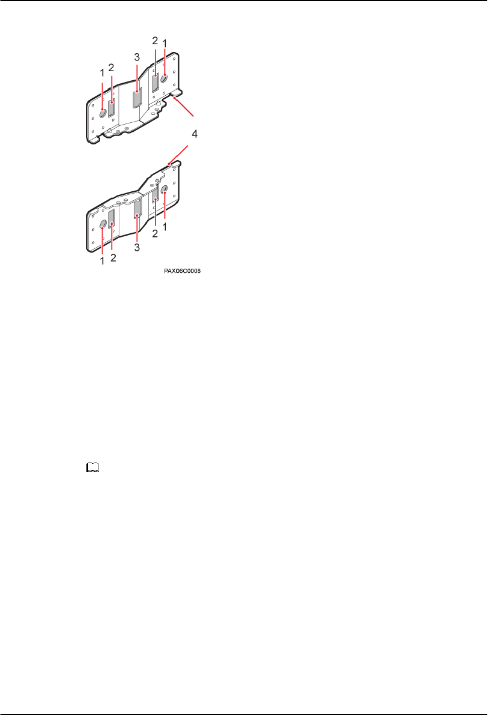
Figure 7-3 Adapting plate assembly for installing a BTS3902E
(1) Mounting hole group A (2) Mounting hole group B (3) Mounting hole group C (4) Adapting plates
7.2 Installing a BTS3902E on a Pole with the Diameter of 60
mm to 114 mm (2.36 in. to 4.49 in.)
This section describes the procedure and precautions for installing a BTS3902E on a pole with
the diameter of 60 mm to 114 mm (2.36 in. to 4.49 in.).
Context
NOTE
It is recommended that the BTS3902E be installed 8000 mm to 15000 mm (315 in. to 590.6 in.) above the floor.
Procedure
Step 1 Determine the position for installing the main mounting bracket.
Step 2 Fit one end of the auxiliary mounting bracket to one dual-nut bolt assembly of the main mounting
bracket.
Step 3 Install the bracket assembly on the pole, and then fit the other end of the auxiliary mounting
bracket to the other dual-nut bolt assembly, as shown in Figure 7-4.
BTS3902E WCDMA
Installation Guide 7 Installing a BTS3902E
Issue Draft A (2011-06-30) Huawei Proprietary and Confidential
Copyright © Huawei Technologies Co., Ltd.
7-3
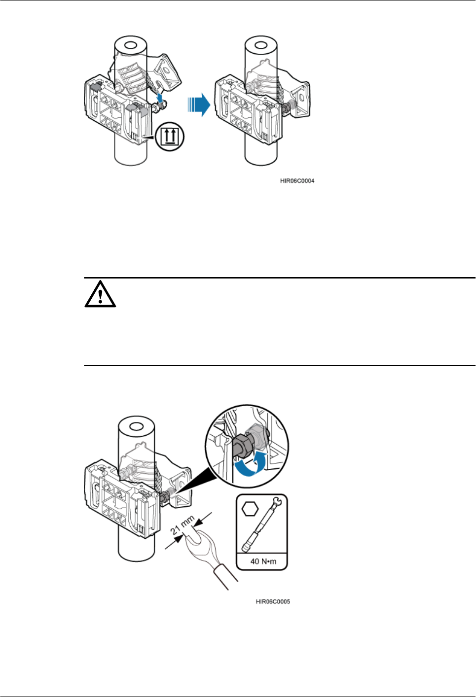
Figure 7-4 Installing the bracket assembly
Step 4 Using a torque wrench, tighten the nuts to 40 N·m (354.03 lbf·in.) to secure the bracket assembly
onto the pole, as shown in Figure 7-5.
CAUTION
Tighten the two dual-nut bolt assemblies alternatively. After the main and auxiliary brackets are
secured properly, measure the spacing between the brackets on both sides and ensure that the
spacing is the same on the two sides.
Figure 7-5 Securing the bracket assembly onto the pole
Step 5 Install the BTS3902E on the main mounting bracket until the BTS3902E snaps shut, as shown
in Figure 7-6.
7 Installing a BTS3902E
BTS3902E WCDMA
Installation Guide
7-4 Huawei Proprietary and Confidential
Copyright © Huawei Technologies Co., Ltd.
Issue Draft A (2011-06-30)
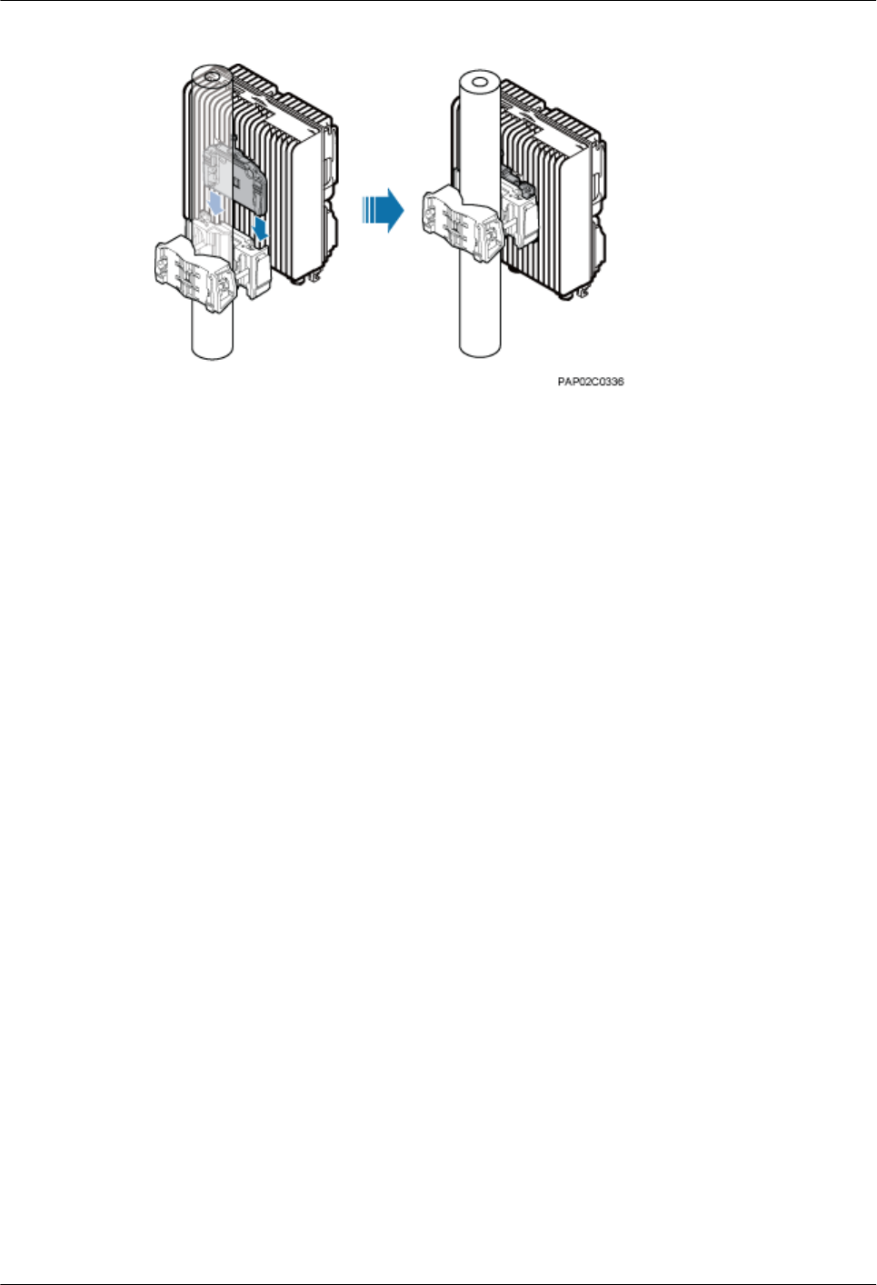
Figure 7-6 Installing the BTS3902E on the main mounting bracket
----End
7.3 Installing a BTS3902E on a Pole with the Diameter of 114
mm to 400 mm (4.49 in. to 15.75 in.)
This section describes the procedure and precautions for installing a BTS3902E on a pole with
the diameter of 114 mm to 400 mm (4.49 in. to 15.75 in.).
Procedure
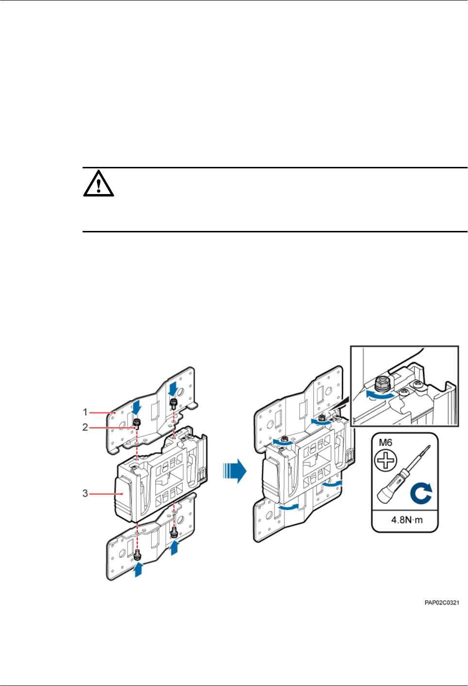
Step 1 Install two adapting plates on the top and bottom of the main mounting bracket. Tighten two
M6x14 screws to 4.8 N·m (42.48 lbf·in.) to secure each of the plate, as shown in Figure 7-7.
BTS3902E WCDMA
Installation Guide 7 Installing a BTS3902E
Issue Draft A (2011-06-30) Huawei Proprietary and Confidential
Copyright © Huawei Technologies Co., Ltd.
7-5
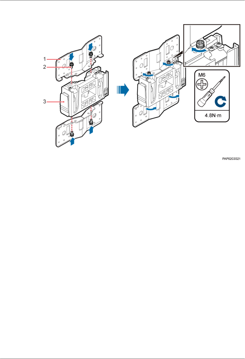
Figure 7-7 Installing the adapting plate assembly
(1) Adapting plate (2) Screw (3) Main mounting bracket
Step 2 Install two hose clamps through the mounting hole group B of the adapting plates, as shown in
Figure 7-8.
7 Installing a BTS3902E
BTS3902E WCDMA
Installation Guide
7-6 Huawei Proprietary and Confidential
Copyright © Huawei Technologies Co., Ltd.
Issue Draft A (2011-06-30)
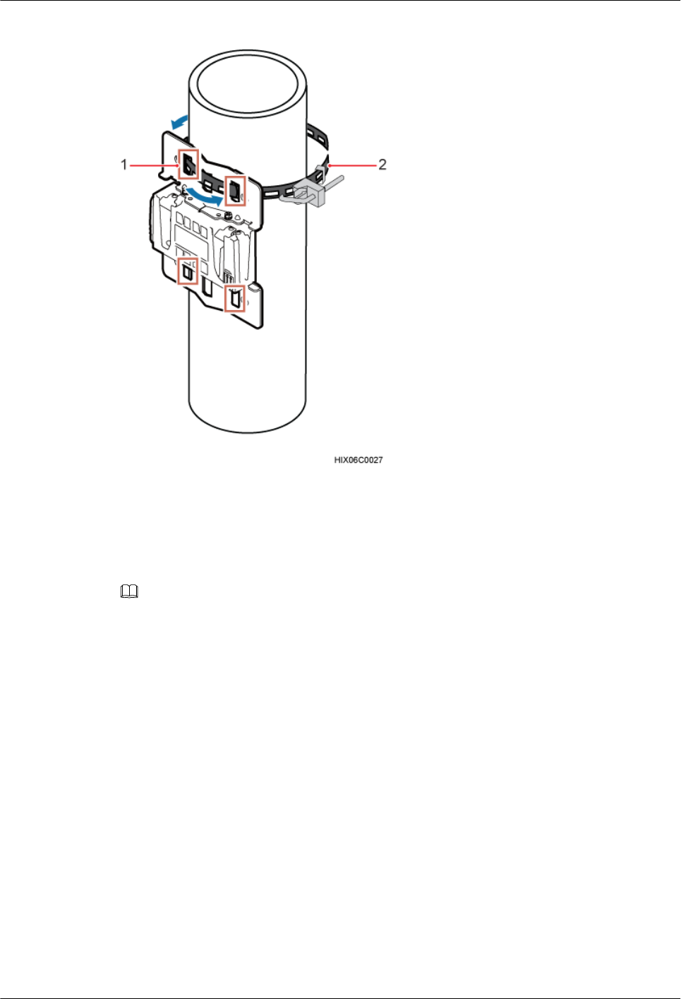
Figure 7-8 Installing the hose clamps
(1) Mounting hole group B (2) Hose clamp
Step 3 Install the securing piece, as shown in Figure 7-9.
1. Secure the hose clamp.
2. Use a level to check whether the adapting plate is on a horizontal plane.
NOTE
Secure the upper hose clamp before securing the lower clamp.
BTS3902E WCDMA
Installation Guide 7 Installing a BTS3902E
Issue Draft A (2011-06-30) Huawei Proprietary and Confidential
Copyright © Huawei Technologies Co., Ltd.
7-7
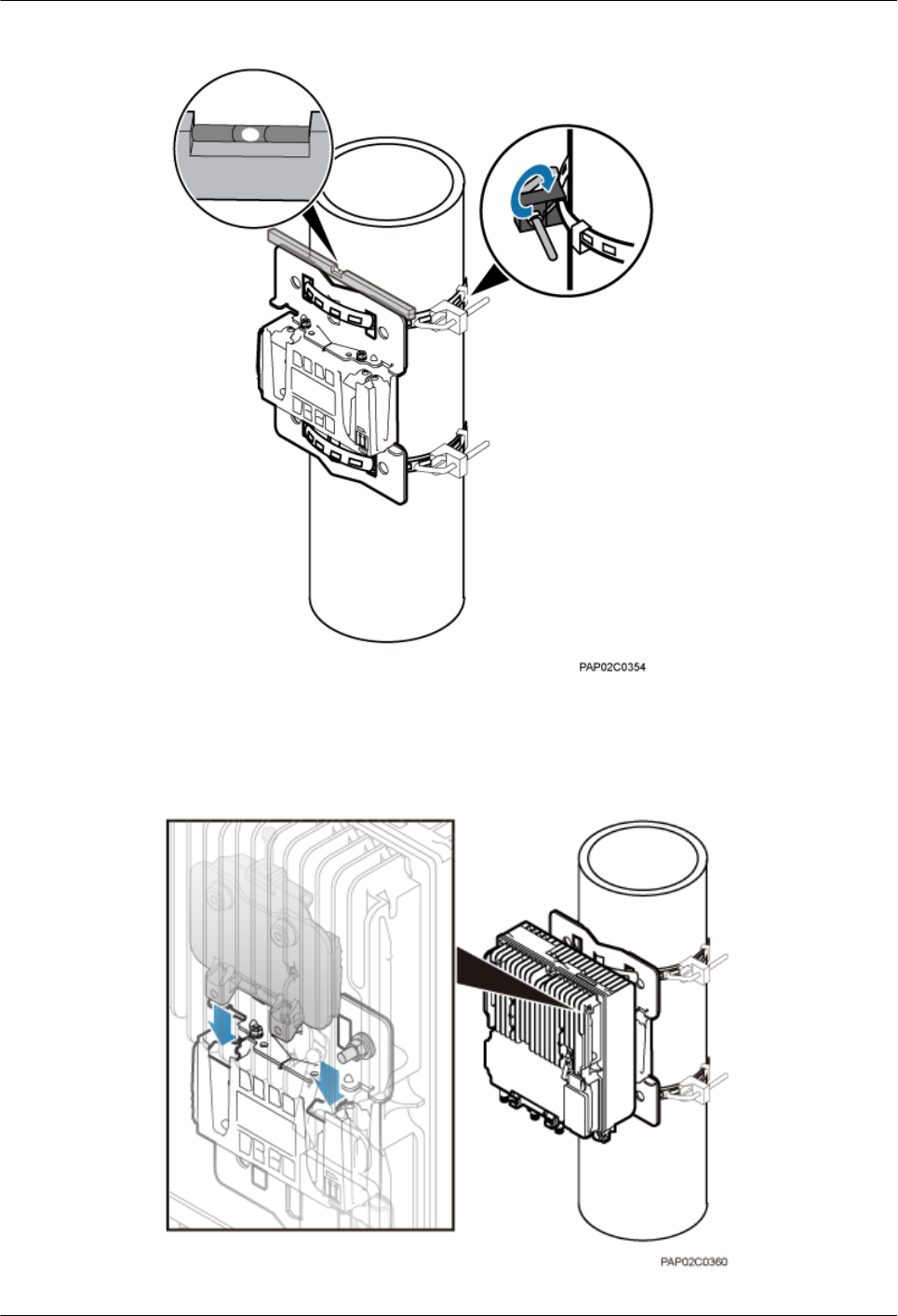
Figure 7-9 Securing the hose clamp
Step 4 Install the BTS3902E on the main mounting bracket until the BTS3902E snaps shut, as shown
in Figure 7-10.
Figure 7-10 Installing the BTS3902E on the main mounting bracket
7 Installing a BTS3902E
BTS3902E WCDMA
Installation Guide
7-8 Huawei Proprietary and Confidential
Copyright © Huawei Technologies Co., Ltd.
Issue Draft A (2011-06-30)
----End
7.4 Installing a BTS3902E on a Wall
This section describes the procedure and precautions for installing a BTS3902E on a wall.
Context
CAUTION
You must use adjustable torque tools to tighten all the screws and nuts to the requirements
described in this document.
Procedure
Step 1 Install two adapting plates on the top and bottom of the main mounting bracket. Tighten two
M6x14 screws to 4.8 N·m (42.48 lbf·in.) to secure each of the plate, as shown in Figure 7-11.
Figure 7-11 Installing the adapting plate assembly
(1) Adapting plate (2) Screw (3) Main mounting bracket
Step 2 Place the adapting plates against the wall, use a level to verify that the plates are horizontal, and
then mark anchor points using a marker, as shown in Figure 7-12.
BTS3902E WCDMA
Installation Guide 7 Installing a BTS3902E
Issue Draft A (2011-06-30) Huawei Proprietary and Confidential
Copyright © Huawei Technologies Co., Ltd.
7-9
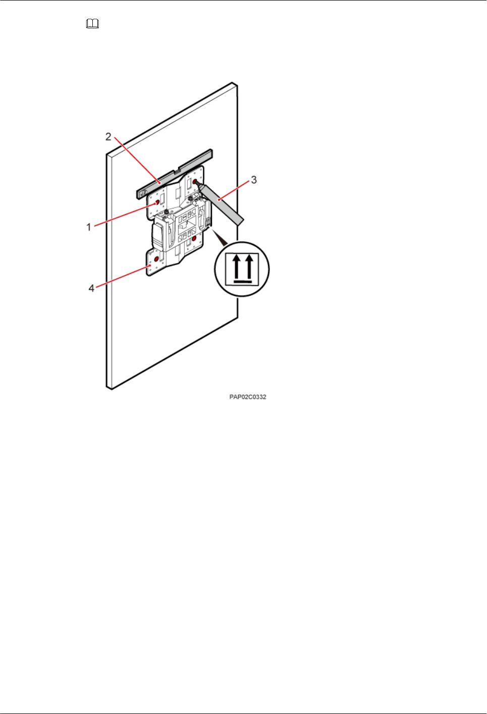
NOTE
It is recommended that the BTS3902E be installed 8000 mm to 15000 mm (315 in. to 590.6 in.) above the floor.
Figure 7-12 Marking the anchor points
(1) Mounting hole group A (2) Level (3) Marker (4) Adapting plate
Step 3 Drill holes at the anchor points, and then install expansion bolt assemblies, as shown in Figure
7-13.
7 Installing a BTS3902E
BTS3902E WCDMA
Installation Guide
7-10 Huawei Proprietary and Confidential
Copyright © Huawei Technologies Co., Ltd.
Issue Draft A (2011-06-30)
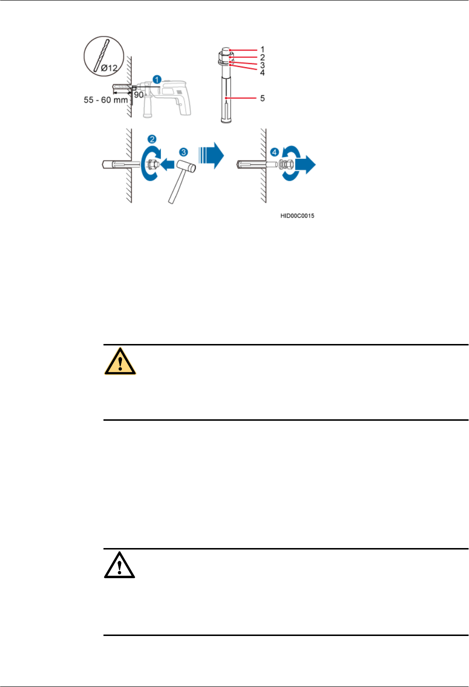
Figure 7-13 Drilling a hole and installing an expansion bolt assembly
(1) M10x80 bolt (2) Nut (3) Spring washer (4) Flat washer (5) Expansion tube
1. Use a hammer drill with a φ12 bit to drill holes perpendicularly with the wall at the marked
anchor points. Ensure that the depth of each hole ranges from 55 mm to 60 mm (2.17 in.
to 2.36 in.).
WARNING
Take proper safety measures before drilling holes to protect your eyes and respiratory tract
against dust.
2. Use a vacuum cleaner to clear dust inside and around the holes, and then measure the inter-
hole spacing. If the spacing is too wide or too narrow, drill holes again.
3. Tighten each expansion bolt slightly and place them perpendicularly into each hole.
4. Hit the expansion bolt using a rubber mallet to enable the expansion tube to completely
enter the hole.
5. Remove the M10x80 bolt, spring washer, and flat washer from each expansion bolt
assembly in sequence.
CAUTION
After disassembling an expansion bolt assembly, ensure that the top of the expansion tube
is on the same level as the wall. Otherwise, the BTS3902E cannot be installed on the wall
evenly and securely.
Step 4 Fit the mounting piece on the expansion bolt, and then use a combination wrench (17 mm [0.67
in.]) to tighten the expansion bolt to 25 N·m (221.27 lbf·in.), as shown in Figure 7-14.
BTS3902E WCDMA
Installation Guide 7 Installing a BTS3902E
Issue Draft A (2011-06-30) Huawei Proprietary and Confidential
Copyright © Huawei Technologies Co., Ltd.
7-11
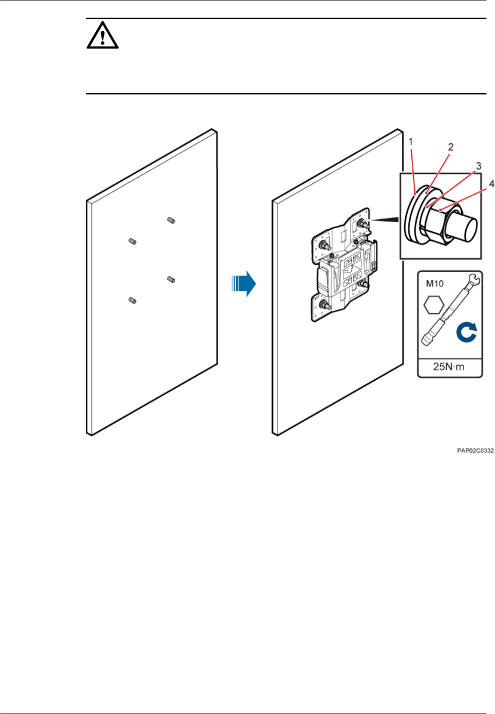
CAUTION
Ensure that the arrow on the main mounting bracket points upwards when installing the securing
piece.
Figure 7-14 Fitting the mounting piece on the expansion bolt
(1) Insulation
washer
(2) Large flat washer (3) Spring washer (4) Nut
Step 5 Install the BTS3902E on the main mounting bracket until the BTS3902E snaps shut, as shown
in Figure 7-15.
7 Installing a BTS3902E
BTS3902E WCDMA
Installation Guide
7-12 Huawei Proprietary and Confidential
Copyright © Huawei Technologies Co., Ltd.
Issue Draft A (2011-06-30)
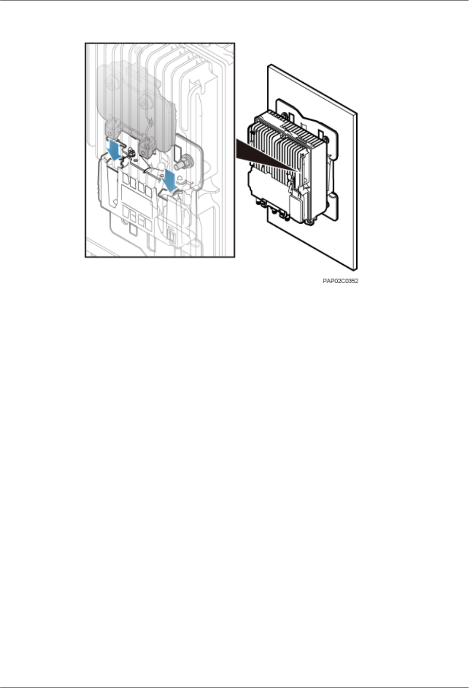
Figure 7-15 Installing the BTS3902E on the main mounting bracket
----End
7.5 Installing a BTS3902E on a Wood Pole
This section describes the procedure and precautions for installing a BTS3902E on a wood pole.
Procedure
Step 1 Drill two holes with the diameter of 18 mm (0.71 in.) on the middle axis of the wood pole,
ensuring that the inter-hole spacing is 203 mm (7.99 in.), as shown in Figure 7-16.
BTS3902E WCDMA
Installation Guide 7 Installing a BTS3902E
Issue Draft A (2011-06-30) Huawei Proprietary and Confidential
Copyright © Huawei Technologies Co., Ltd.
7-13
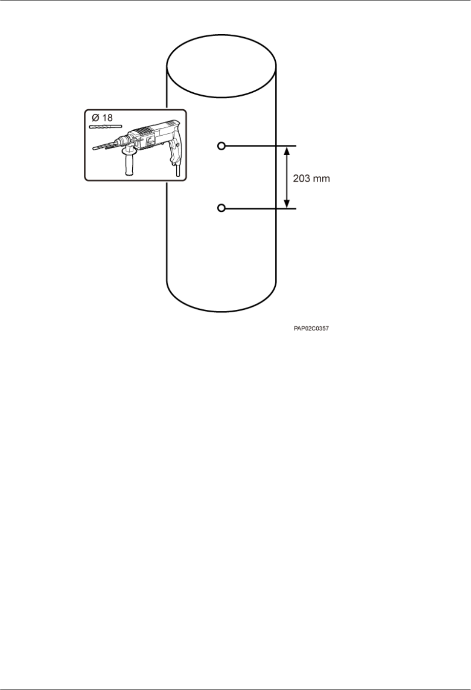
Figure 7-16 Drilling holes
Step 2 Install two adapting plates on the top and bottom of the main mounting bracket. Tighten two
M6x14 screws to 4.8 N·m (42.48 lbf·in.) to secure each of the plate, as shown in Figure 7-17.
7 Installing a BTS3902E
BTS3902E WCDMA
Installation Guide
7-14 Huawei Proprietary and Confidential
Copyright © Huawei Technologies Co., Ltd.
Issue Draft A (2011-06-30)

Figure 7-17 Installing the adapting plate assembly
(1) Adapting plate (2) Screw (3) Main mounting bracket
Step 3 Install the securing piece, as shown in Figure 7-18.
1. Align the mounting hole group C with the mounting holes in the wood pole.
2. Lead the two long M16 bolts with spacers through the upper and lower mounting holes.
BTS3902E WCDMA
Installation Guide 7 Installing a BTS3902E
Issue Draft A (2011-06-30) Huawei Proprietary and Confidential
Copyright © Huawei Technologies Co., Ltd.
7-15
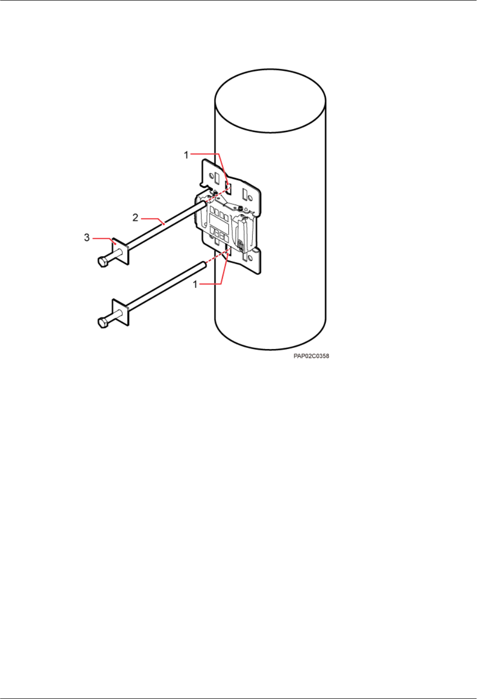
Figure 7-18 Securing the securing pieces
(1) Mounting hole group C (2) Bolt (3) Spacer
Step 4 Tighten the nuts to 80 N·m (708.06 lbf·in.), as shown in Figure 7-19.
7 Installing a BTS3902E
BTS3902E WCDMA
Installation Guide
7-16 Huawei Proprietary and Confidential
Copyright © Huawei Technologies Co., Ltd.
Issue Draft A (2011-06-30)
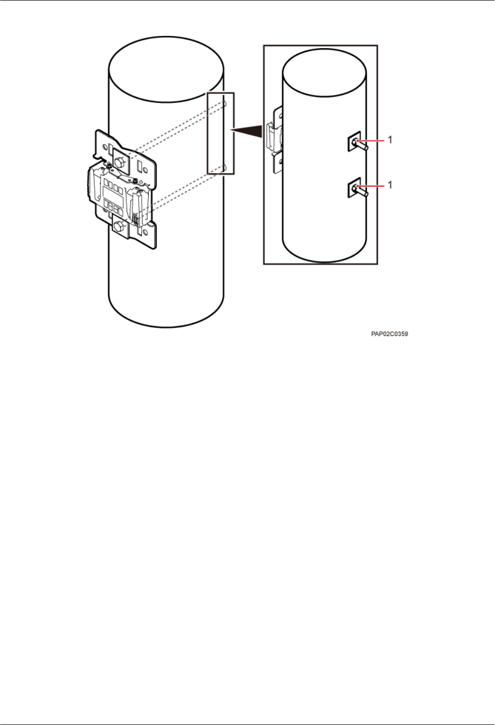
Figure 7-19 Tightening nuts
(1) Nut
Step 5 Install the BTS3902E on the main mounting bracket until the BTS3902E snaps shut, as shown
in Figure 7-20.
BTS3902E WCDMA
Installation Guide 7 Installing a BTS3902E
Issue Draft A (2011-06-30) Huawei Proprietary and Confidential
Copyright © Huawei Technologies Co., Ltd.
7-17
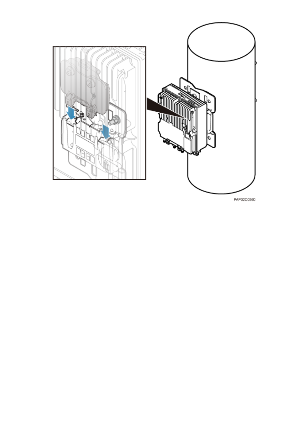
Figure 7-20 Installing the BTS3902E on the main mounting bracket
----End
7 Installing a BTS3902E
BTS3902E WCDMA
Installation Guide
7-18 Huawei Proprietary and Confidential
Copyright © Huawei Technologies Co., Ltd.
Issue Draft A (2011-06-30)

8 Installing an AC Surge Protection Box and
Related Cables
About This Chapter
This chapter describes the dimensions, installation clearance requirements, and installation
options of an AC surge protection box. It also describes the procedure for installing the surge
protection box. An AC surge protection box can be configured when a BTS3902E is installed
outdoors.
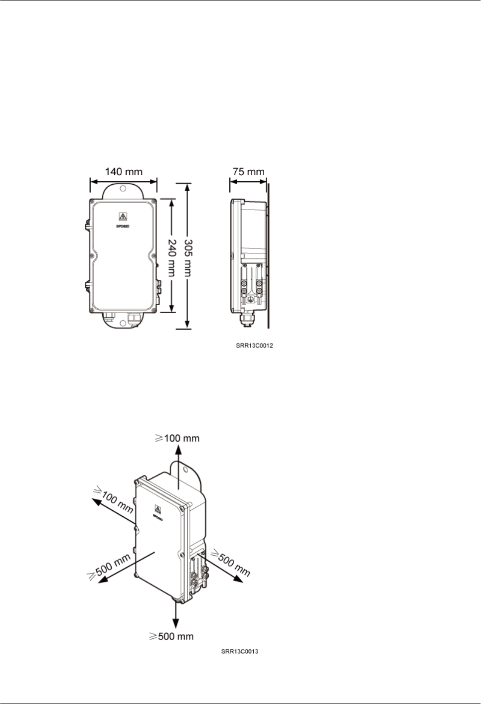
8.1 Dimensions and Installation Clearance Requirements of an AC Surge Protection Box
This section describes the dimensions and installation clearance requirements for an AC surge
protection box.
8.2 Installation Options of an AC Surge Protection Box
This section describes installation options of an AC surge protection box. An AC surge protection
box can be installed on a pole, wall, or wood pole.
8.3 Installing an AC Surge Protection Box
This section describes the procedure for installing an AC surge protection box.
8.4 Installing Cables for an AC Surge Protection Box
This section describes the procedure for installing cables for an AC surge protection box.
BTS3902E WCDMA
Installation Guide 8 Installing an AC Surge Protection Box and Related Cables
Issue Draft A (2011-06-30) Huawei Proprietary and Confidential
Copyright © Huawei Technologies Co., Ltd.
8-1
8.1 Dimensions and Installation Clearance Requirements of
an AC Surge Protection Box
This section describes the dimensions and installation clearance requirements for an AC surge
protection box.
Figure 8-1 shows the dimensions of an AC surge protection box.
Figure 8-1 Dimensions of an AC surge protection box
Figure 8-2 shows the recommended installation clearance for an AC surge protection box.
Figure 8-2 Recommended installation clearance for an AC surge protection box
8 Installing an AC Surge Protection Box and Related Cables
BTS3902E WCDMA
Installation Guide
8-2 Huawei Proprietary and Confidential
Copyright © Huawei Technologies Co., Ltd.
Issue Draft A (2011-06-30)
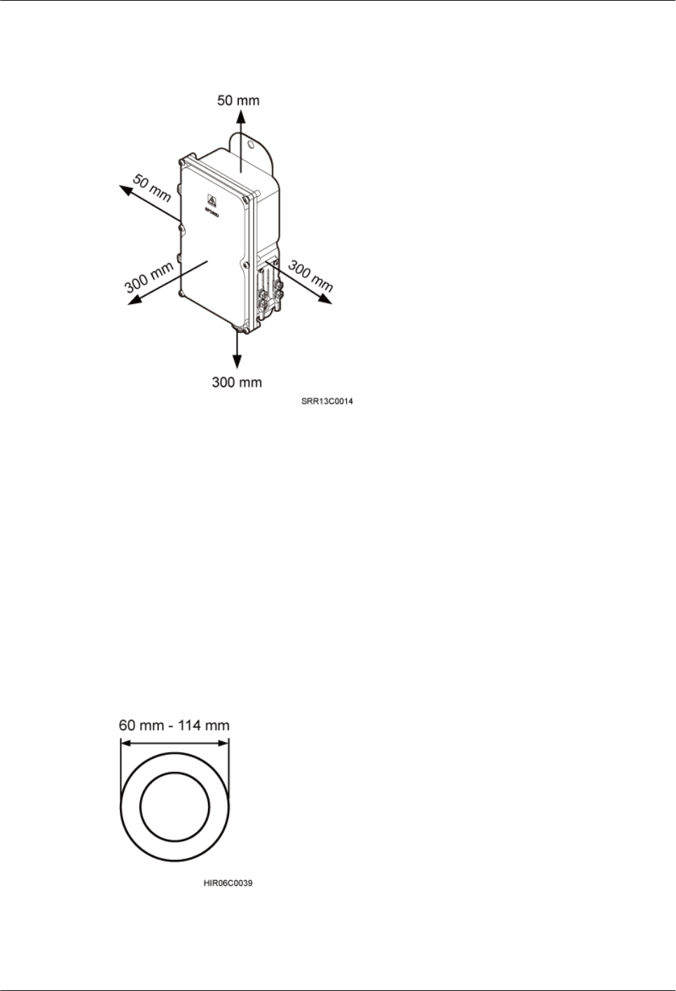
Figure 8-3 shows the minimum installation clearance for an AC surge protection box.
Figure 8-3 Minimum installation clearance for an AC surge protection box
8.2 Installation Options of an AC Surge Protection Box
This section describes installation options of an AC surge protection box. An AC surge protection
box can be installed on a pole, wall, or wood pole.
Installing an AC Surge Protection Box on a Pole with the Diameter of 60 mm to 114
mm (2.36 in. to 4.49 in.)
Figure 8-4 shows the diameter of a pole for installing an AC surge protection box.
Figure 8-4 Diameter of a pole
Figure 8-5 shows an AC surge protection box installed on a pole.
BTS3902E WCDMA
Installation Guide 8 Installing an AC Surge Protection Box and Related Cables
Issue Draft A (2011-06-30) Huawei Proprietary and Confidential
Copyright © Huawei Technologies Co., Ltd.
8-3
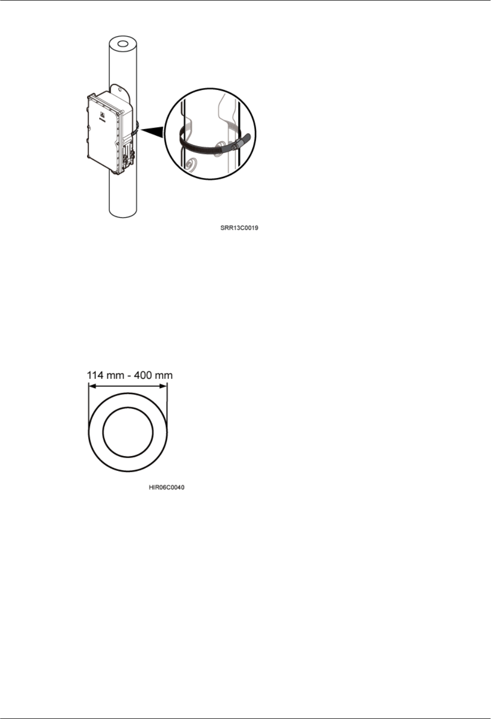
Figure 8-5 AC surge protection box installed on a pole
Installing an AC Surge Protection Box on a Pole with the Diameter of 114 mm to
400 mm (4.49 in. to 15.75 in.)
Figure 8-6 shows the diameter of a pole for installing an AC surge protection box.
Figure 8-6 Diameter of a pole
Figure 8-7 shows an AC surge protection box installed on a pole.
8 Installing an AC Surge Protection Box and Related Cables
BTS3902E WCDMA
Installation Guide
8-4 Huawei Proprietary and Confidential
Copyright © Huawei Technologies Co., Ltd.
Issue Draft A (2011-06-30)
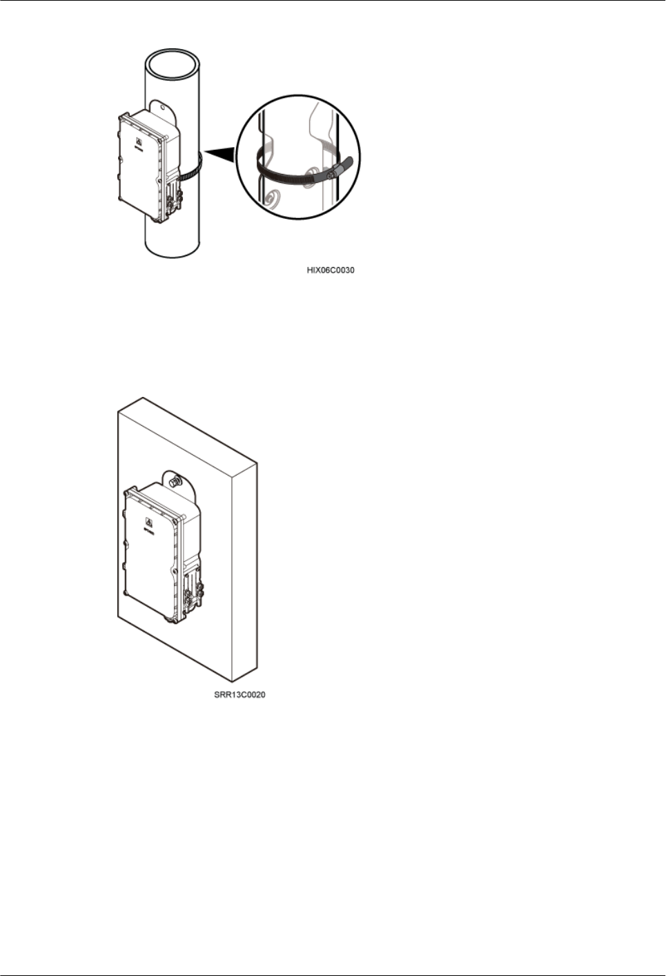
Figure 8-7 AC surge protection box installed on a pole
Installing an AC Surge Protection Box on a Wall
Figure 8-8 shows an AC surge protection box installed on a wall.
Figure 8-8 AC surge protection box installed on a wall
Installing an AC Surge Protection Box on a Wood Pole
Figure 8-9 shows an AC surge protection box installed on a wood pole.
BTS3902E WCDMA
Installation Guide 8 Installing an AC Surge Protection Box and Related Cables
Issue Draft A (2011-06-30) Huawei Proprietary and Confidential
Copyright © Huawei Technologies Co., Ltd.
8-5

Figure 8-9 AC surge protection box installed on a wood pole
8.3 Installing an AC Surge Protection Box
This section describes the procedure for installing an AC surge protection box.
Procedure
lInstall an AC surge protection box on a pole, as shown in Figure 8-10.
NOTE
lWhen the diameter of the pole ranges from 60 mm to 114 mm (2.36 in. to 4.49 in.), the hose clamps
delivered with the AC surge protection box is used.
lWhen the diameter of the pole ranges from 114 mm to 400 mm (4.49 in. to 15.75 in.), the hose clamps
purchased locally is used.
Figure 8-10 Installing the AC surge protection box on a pole
8 Installing an AC Surge Protection Box and Related Cables
BTS3902E WCDMA
Installation Guide
8-6 Huawei Proprietary and Confidential
Copyright © Huawei Technologies Co., Ltd.
Issue Draft A (2011-06-30)

1. Loosen the hose clamp.
2. Lead the clamp through the gap between the rear mounting plate and the case of the
AC surge protection box.
3. Install the hose clamp around the pole, and secure the clamp.
NOTE
If the diameter of the pole around which the clamp is installed is small, cut the extra part of the clamp.
lInstall an AC surge protection box on a wall.
1. Place the rear mounting plate of the AC surge protection box against the wall, use a
level to verify that the plate is horizontal, and then mark anchor points using a marker,
as shown in Figure 8-11.
Figure 8-11 Marking the anchor points
2. Use a hammer drill with a Ø14 bit to drill holes at the anchor points, and install
expansion bolts, as shown in Figure 8-12.
NOTE
After disassembling the expansion bolt assemblies, discard the plastic tubes.
BTS3902E WCDMA
Installation Guide 8 Installing an AC Surge Protection Box and Related Cables
Issue Draft A (2011-06-30) Huawei Proprietary and Confidential
Copyright © Huawei Technologies Co., Ltd.
8-7
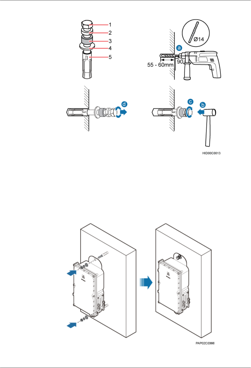
Figure 8-12 Installing an expansion bolt
(1) M10x65 bolt (2) Spring washer 10 (3) Plastic tube (4) Flat washer 10 (5) Expansion tube
3. Align the AC surge protection box with the holes in the wall, and tighten the expansion
bolts to 30 N·m (265.52 lbf·in.), as shown in Figure 8-13.
Figure 8-13 Installing an AC surge protection box
lInstall an AC surge protection box on a wood pole.
8 Installing an AC Surge Protection Box and Related Cables
BTS3902E WCDMA
Installation Guide
8-8 Huawei Proprietary and Confidential
Copyright © Huawei Technologies Co., Ltd.
Issue Draft A (2011-06-30)
1. Place the rear mounting plate of the AC surge protection box against the wood pole,
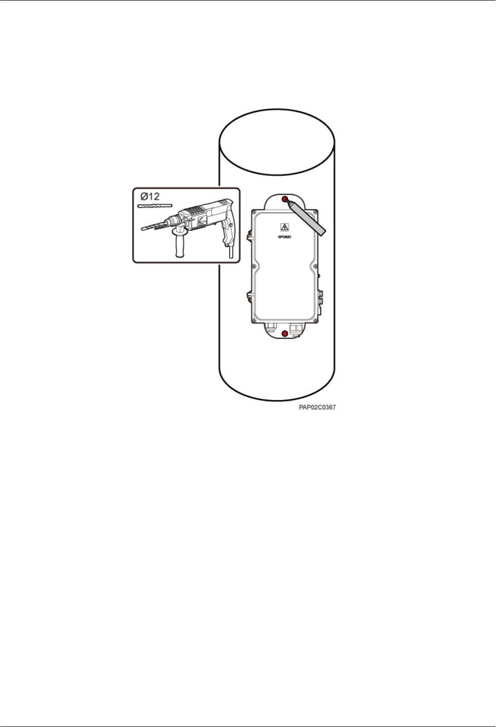
determine the anchor points on the middle axis, and then mark the anchor points.
2. Drill holes with the diameter of 12 mm (0.47 in.) at the anchor points through the
wood pole, as shown in Figure 8-14.
Figure 8-14 Drilling holes
3. Align the AC surge protection box with the holes in the wood pole, lead the two long
M10 bolts with spacers through the two mounting holes and holes, and then install the
bolts on the wood pole, as shown in Figure 8-15.
BTS3902E WCDMA
Installation Guide 8 Installing an AC Surge Protection Box and Related Cables
Issue Draft A (2011-06-30) Huawei Proprietary and Confidential
Copyright © Huawei Technologies Co., Ltd.
8-9

Figure 8-15 Installing the AC surge protection box on the wood pole
4. Tighten the nuts to 30 N·m (265.52 lbf·in.), as shown in Figure 8-16.
8 Installing an AC Surge Protection Box and Related Cables
BTS3902E WCDMA
Installation Guide
8-10 Huawei Proprietary and Confidential
Copyright © Huawei Technologies Co., Ltd.
Issue Draft A (2011-06-30)
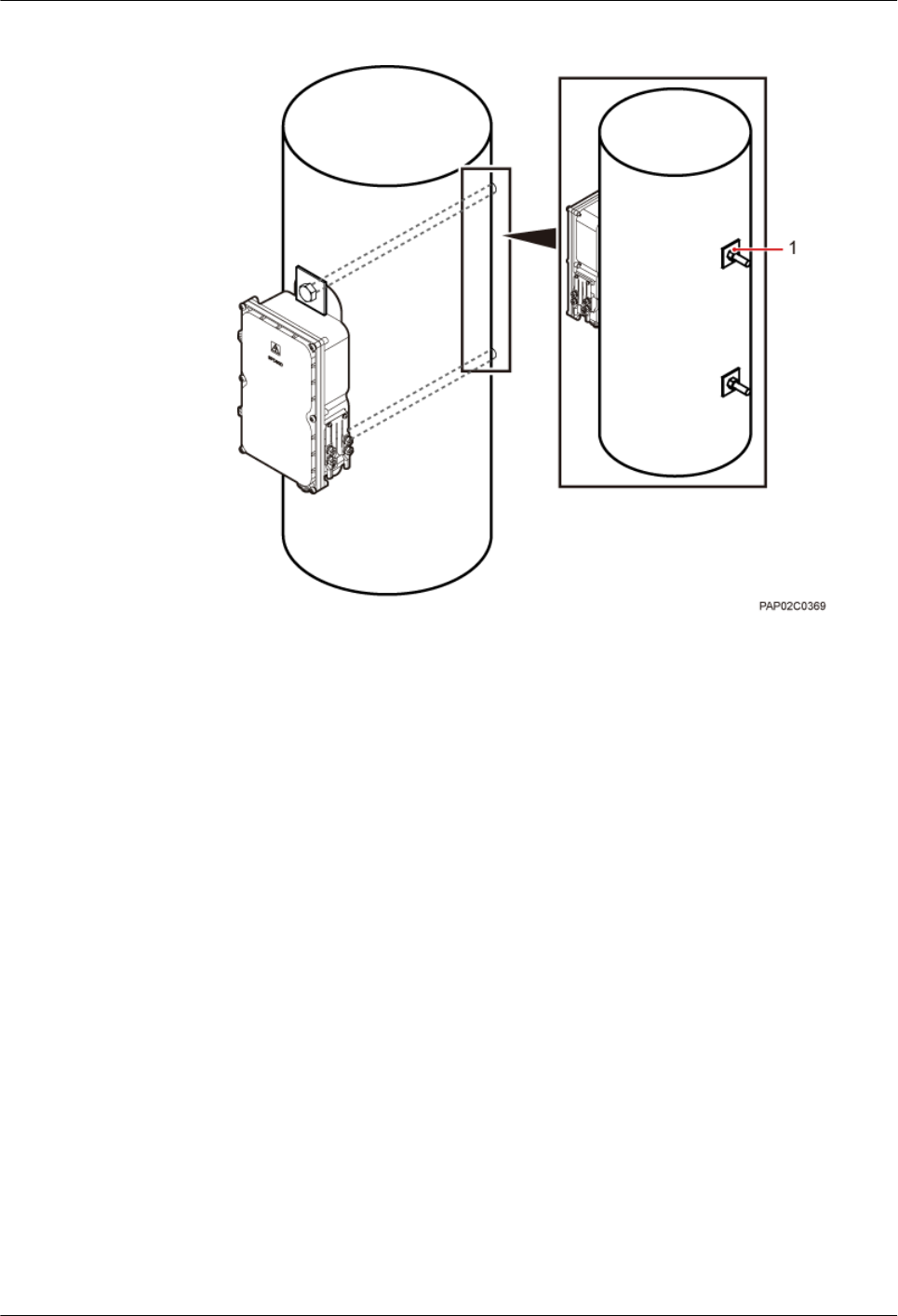
Figure 8-16 Tightening the nuts
(1) Nut
----End
8.4 Installing Cables for an AC Surge Protection Box
This section describes the procedure for installing cables for an AC surge protection box.
Prerequisite
Add OT terminals to the power cables for the AC surge protection box on the surge protection
box side. For details, see Adding OT Terminals to the Power Cable Connected to the AC Surge
Protection Box.
Procedure
Step 1 Loosen the screws on the AC surge protection box using the M4 Phillips screwdriver and open
the cover plate. Then, remove the thread-lock sealing nut from the PG connector of the surge
protection box, and store waterproof blocks properly, as shown in Figure 8-17.
BTS3902E WCDMA
Installation Guide 8 Installing an AC Surge Protection Box and Related Cables
Issue Draft A (2011-06-30) Huawei Proprietary and Confidential
Copyright © Huawei Technologies Co., Ltd.
8-11
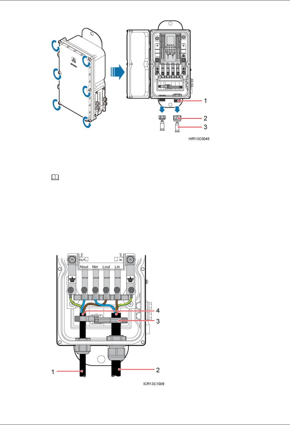
Figure 8-17 Opening the cover plate of the AC surge protection box
(1) PG connector (2) Thread-lock sealing nut of the PG connector (3) Waterproof block
NOTE
Do not use the removed thread-lock sealing nut of the PG connector with the thread-lock sealing nuts on
other surge protection boxes.
Step 2 Glide the thread-lock sealing nut and then the PG connector over the power cable.
Step 3 Connect the power cables to the AC surge protection box, as shown in Figure 8-18. The power
cable on the left connects the BTS3902E and the AC surge protection box, and the power cable
on the right connects the AC surge protection box and the external power device.
Figure 8-18 Cable connections of the AC surge protection box
(1) Power cable between the BTS3902E
and the AC surge protection box
(2) Power cable between the AC surge
protection box and the external power
device
(3) Clip (4) Insulation layer
8 Installing an AC Surge Protection Box and Related Cables
BTS3902E WCDMA
Installation Guide
8-12 Huawei Proprietary and Confidential
Copyright © Huawei Technologies Co., Ltd.
Issue Draft A (2011-06-30)
1. Lead the power cable between the surge protection box and the external power device
through the PG connector labeled IN. Connect the OT terminals of the brown, blue, and
yellow/green core wires to the Lin, Nin, and GND ports on the surge protection box
respectively.
2. Route the power cable between the BTS3902E and the AC surge protection box through
the PG connector labeled OUT. Connect the OT terminals of the blue, brown, and green
and yellow wires to the Nout, Lout, and GND ports in the AC surge protection box,
respectively.
3. Tighten the thread-lock sealing nut, and then use a wrench to tighten the PG connector to
ensure it is waterproofed properly.
Step 4 Fasten the power cables using clips.
NOTE
Ensure that the insulation layer of each power cable is fastened using clips.
Step 5 Close the cover plate of the surge protection box and tighten the screw to 1.4 N·m (123.91 lbf.in.)
using an M4 Phillips screwdriver, as shown in Figure 8-19.
Figure 8-19 Closing the cover plate of the AC surge protection box
Step 6 Wrap the joints of the corrugated pipe and power cables using waterproof tape and polyvinyl
chloride (PVC) insulation tape, as shown in Figure 8-20. Wrap the joints using waterproof tape
before using PVC insulation tape.
TIP
Wrap each connector with three layers of waterproof tape, from bottom up, then from top down, and finally
from bottom up. Do not cut the tape until all the three layers of the tape are already wrapped. When wrapping
tape, be sure that each layer of tape overlaps more than 50% of the preceding layer.
BTS3902E WCDMA
Installation Guide 8 Installing an AC Surge Protection Box and Related Cables
Issue Draft A (2011-06-30) Huawei Proprietary and Confidential
Copyright © Huawei Technologies Co., Ltd.
8-13

Figure 8-20 Securing AC power cables
(1) Corrugated pipe (2) Connector between corrugated pipes
Step 7 Bind the cables using cable ties at equal spacing of 30 cm (11.81 in.) and verify that the bend
radius of the corrugated pipe is not less than 60 mm (2.36 in.).
Step 8 Install the PGND cable and equipotential cable, as shown in Figure 8-21.
Figure 8-21 Installing the PGND cable and equipotential cable
(1) PGND cable (2) Equipotential cable
8 Installing an AC Surge Protection Box and Related Cables
BTS3902E WCDMA
Installation Guide
8-14 Huawei Proprietary and Confidential
Copyright © Huawei Technologies Co., Ltd.
Issue Draft A (2011-06-30)

----End
BTS3902E WCDMA
Installation Guide 8 Installing an AC Surge Protection Box and Related Cables
Issue Draft A (2011-06-30) Huawei Proprietary and Confidential
Copyright © Huawei Technologies Co., Ltd.
8-15

9 Installing Cables
About This Chapter
This chapter describes the procedure and precautions for installing the PGND cables, power
cables, and transmission cables for a BTS3902E in various scenarios. Based on actual
requirements, and it also describes how to install an optional monitoring signal cable as required.
9.1 Cabling Requirements
Cables must be routed according to the specified cabling requirements to prevent signal
interference.
9.2 Cable Connections
The cable connections of the BTS3902E vary depending on the number of BTS3902Es and the
BTS3902E port.
9.3 Installing a PGND Cable and Equipotential Cable
The protection ground (PGND) cable and equipotential cable must be installed based on actual
requirements.
9.4 Installing a BTS3902E Power Cable
A BTS3902E power cable connects the BTS3902E to an external power device, feeding external
power into the BTS3902E.
9.5 (Optional) Installing a BTS3902E RF Jumper
You must install a radio frequency (RF) jumper when a BTS3902E uses an external antenna.
9.6 Installing Transmission Cables
When a BTS3902E is installed outdoors, a fast Ethernet or gigabit Ethernet (FE/GE) cable or
FE/GE fiber optic cable must be installed based on actual requirements.
9.7 Installing the Housing
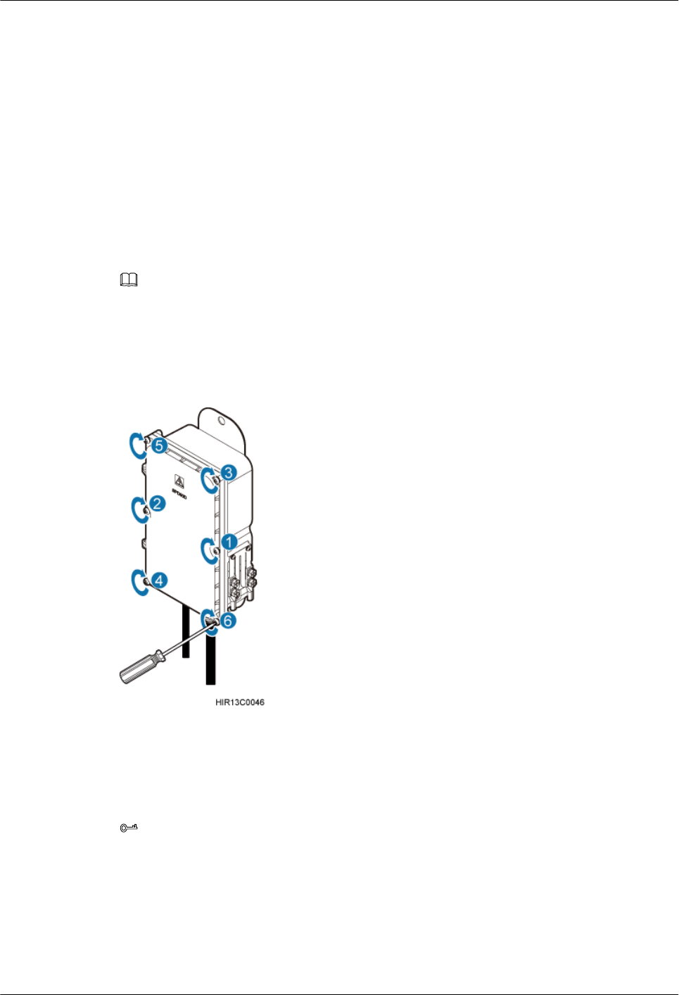
This chapter describes the procedures for installing the upper housing and optional camouflage
shell for a BTS3902E after the BTS3902E and related cables are installed.
9.8 Checking the BTS3902E Hardware Installation
This chapter describes how to check the hardware installation after a BTS3902E is installed.
9.9 Performing a Power-On Check on the BTS3902E
This chapter describes the procedure for performing a power-on check on the BTS3902E.
9.10 Appendix
BTS3902E WCDMA
Installation Guide 9 Installing Cables
Issue Draft A (2011-06-30) Huawei Proprietary and Confidential
Copyright © Huawei Technologies Co., Ltd.
9-1

This section describes the procedure for adding an easy power receptacle (pressfit type)
connector.This section describes the procedure for adding OT terminals.This section describes
the procedure for adding OT terminals to the surge protection box side of the power cable for
the AC surge protection box.
9 Installing Cables
BTS3902E WCDMA
Installation Guide
9-2 Huawei Proprietary and Confidential
Copyright © Huawei Technologies Co., Ltd.
Issue Draft A (2011-06-30)

9.1 Cabling Requirements
Cables must be routed according to the specified cabling requirements to prevent signal
interference.
NOTE
If a cable listed below is not required, skip the routing requirements of the cable.
General Cabling Requirements
The bending radius of the cables must meet the following specifications:
lThe bending radius of the 7/8'' feeder must be more than 250 mm (9.84 in.), and the bending
radius of the 5/4'' feeder must be more than 380 mm (14.96 in.).
lThe bending radius of the 1/4'' jumper must be more than 35 mm (1.38 in.). The bending
radius of the super-flexible 1/2'' jumper must be more than 50 mm (1.97 in.), and the bending
radius of the ordinary 1/2'' jumper must be more than 127 mm (5 in.).
lThe bending radius of the power cable or PGND cable must be at least five times the
diameter of the cable.
lThe bending radius of an fiber optic cable is at least 20 times the diameter of the fiber optic
cable.
lThe bending radius of the signal cable must be at least five times the diameter of the cable.
The cables must be bound as follows:
lThe cables must be bound tightly and neatly. The sheaths of the cables must not be damaged.
lThe cable ties must face the same direction, and those at the same horizontal line must be
in a straight line. Extra length of cable ties must be cut.
lLabels or nameplates must be attached to the cables after they are installed.
The cables must be routed as follows:
lDifferent types of cables must be installed in an untangled and orderly fashion.
lDifferent types of cables must be routed in parallel or separated by special objects.
Special Cabling Requirements
Cabling requirements for power cables are as follows:
lMultiple power cables must be bound when routed.
lPower cables must be installed in the position specified in engineering design documents.
lIf the length of power cables is insufficient, replace the cables rather than adding connectors
or soldering joints to lengthen the cables.
Cabling requirements for PGND cables are as follows:
lPGND cables for the base station must be connected to the same ground bar.
lPGND cables must be buried in the ground or routed indoors. They should not be routed
overhead before they are led into the equipment room.
lThe exterior of the coaxial wire and the shield layer of the shielded cable must have proper
electrical contact with the metal surface of the equipment to which they are connected.
BTS3902E WCDMA
Installation Guide 9 Installing Cables
Issue Draft A (2011-06-30) Huawei Proprietary and Confidential
Copyright © Huawei Technologies Co., Ltd.
9-3

lPGND cables and signal cables must be installed in an untangled and orderly fashion. A
certain distance must be reserved between them to prevent interference from each other.
lFuses or switches must not be installed on the PGND cables.
lOther devices must not be used for electrical connections of the PGND cables.
lAll the metal parts in the housing of the equipment must be reliably connected to the ground
terminal.
Cabling requirements for fiber optic cables are as follows:
lDo not stretch, step on, or place heavy objects on fiber optic cables. Keep the cables away
from sharp objects.
lWhen fiber optic cables are routed, the extra length of the cables must be coiled around
special devices, such as a fiber coiler.
lWhen coiling fiber optic cables, apply even strength. Do not bend the cables with force.
lVacant optical connectors must be covered with dustproof caps.
9.2 Cable Connections
The cable connections of the BTS3902E vary depending on the number of BTS3902Es and the
BTS3902E port.
Cable Connections of the BTS3902E
Figure 9-1 shows the cable connections of a single BTS3902E implementing transmission over
an electrical port.
9 Installing Cables
BTS3902E WCDMA
Installation Guide
9-4 Huawei Proprietary and Confidential
Copyright © Huawei Technologies Co., Ltd.
Issue Draft A (2011-06-30)
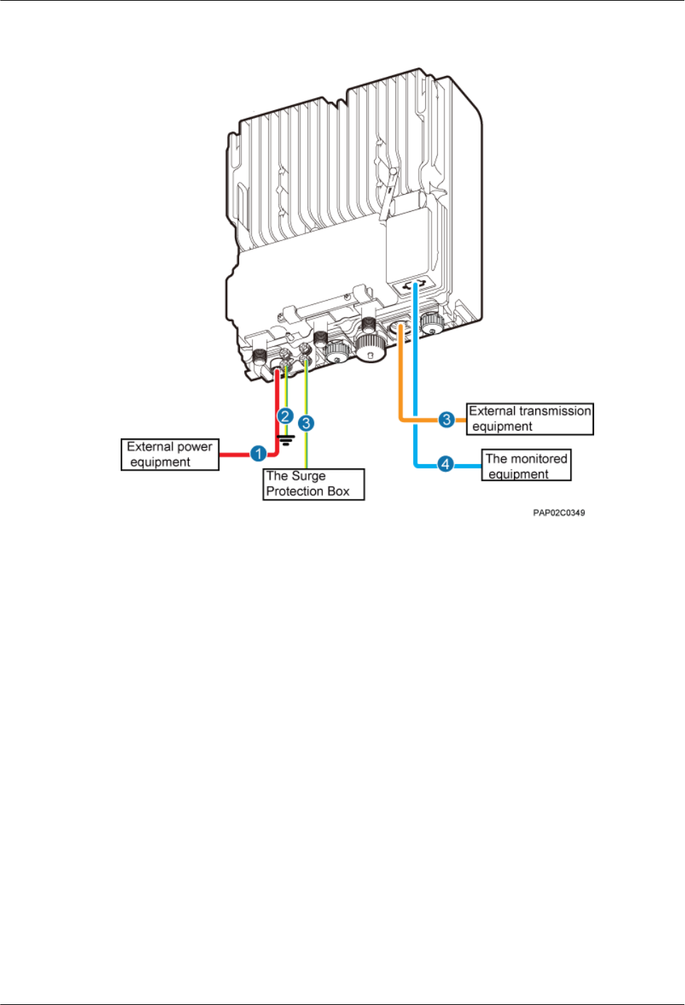
Figure 9-1 Cable connections of a single BTS3902E implementing transmission over an
electrical port
(1) BTS3902E power cable (2) PGND cable (optional) (3) Equipotential cable (optional)
(4) Fast Ethernet or gigabit Ethernet
(FE/GE) cable
(5) BTS3902E monitoring signal
cable (optional)
—
Figure 9-2 shows the cable connections of a single BTS3902E implementing transmission over
an optical port.
BTS3902E WCDMA
Installation Guide 9 Installing Cables
Issue Draft A (2011-06-30) Huawei Proprietary and Confidential
Copyright © Huawei Technologies Co., Ltd.
9-5

Figure 9-2 Cable connections of a single BTS3902E implementing transmission over an optical
port
(1) BTS3902E power cable (2) PGND cable (optional) (3) Equipotential cable (optional)
(4) FE/GE fiber optic cable (5) BTS3902E monitoring signal
cable (optional)
—
Figure 9-3 shows the cable connections of a single BTS3902E implementing power over
Ethernet (POE) over an electrical port and transmission using a fiber optic cable.
9 Installing Cables
BTS3902E WCDMA
Installation Guide
9-6 Huawei Proprietary and Confidential
Copyright © Huawei Technologies Co., Ltd.
Issue Draft A (2011-06-30)

Figure 9-3 Cable connections of a single BTS3902E implementing POE over an electrical port
and transmission using a fiber optic cable
(1) BTS3902E power cable (2) PGND cable (optional) (3) Equipotential cable (optional)
(4) FE/GE cable (5) FE/GE fiber optic cable (6) BTS3902E monitoring signal cable
(optional)
Figure 9-4 shows the cable connections of two BTS3902Es implementing transmission and
cascading using fiber optic cables.
BTS3902E WCDMA
Installation Guide 9 Installing Cables
Issue Draft A (2011-06-30) Huawei Proprietary and Confidential
Copyright © Huawei Technologies Co., Ltd.
9-7
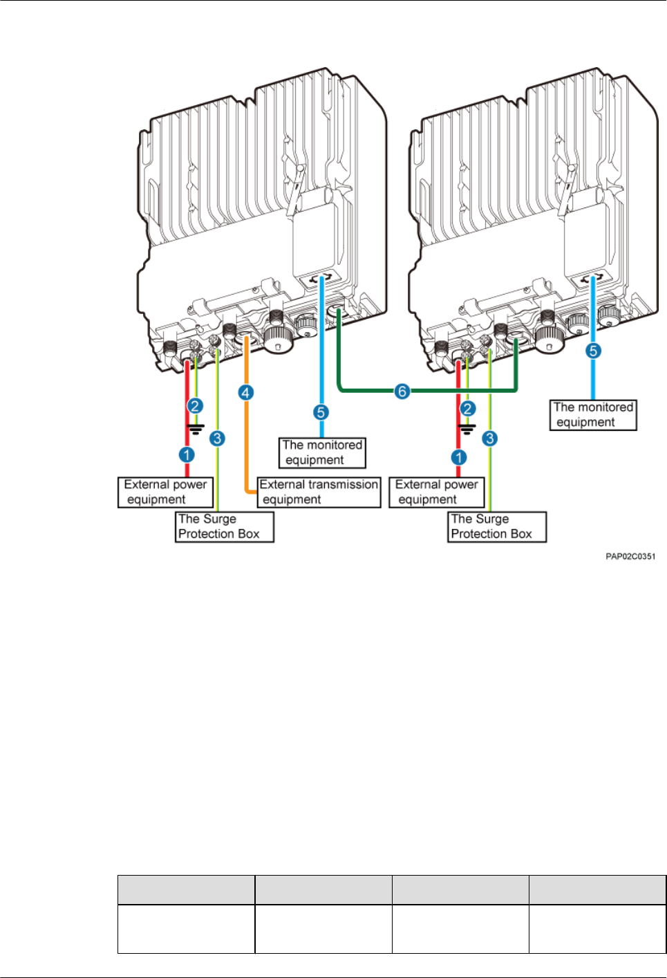
Figure 9-4 Cable connections of two BTS3902Es implementing transmission and cascading
using fiber optic cables
(1) BTS3902E power cable (2) PGND cable (optional) (3) Equipotential cable (optional)
(4) FE/GE fiber optic cable (5) BTS3902E monitoring signal
cable (optional)
(6) FE/GE fiber optic cable for
cascading
9.3 Installing a PGND Cable and Equipotential Cable
The protection ground (PGND) cable and equipotential cable must be installed based on actual
requirements.
Context
Table 9-1 lists the specifications of the PGND cable and equipotential cable.
Table 9-1 Specifications of the BTS3902E PGND cable and equipotential cable
Cable One End The Other End Remarks
PGND cable OT terminal (M6, 16
mm2 [0.025 in.2])
OT terminal (M6, 16
mm2 [0.025 in.2])
Green and yellow
9 Installing Cables
BTS3902E WCDMA
Installation Guide
9-8 Huawei Proprietary and Confidential
Copyright © Huawei Technologies Co., Ltd.
Issue Draft A (2011-06-30)
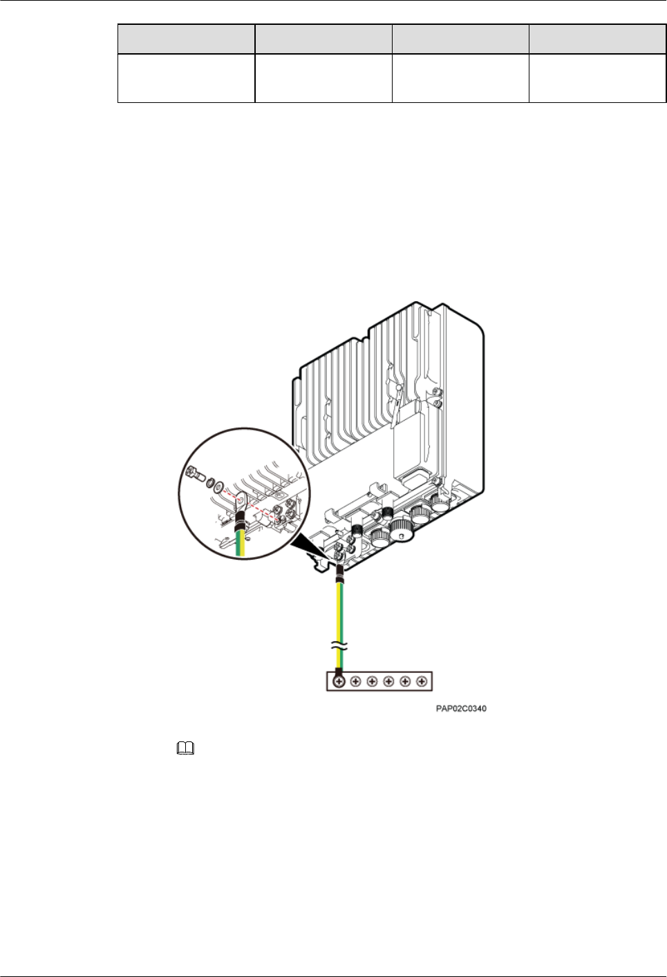
Cable One End The Other End Remarks
Equipotential cable OT terminal (M6, 16
mm2 [0.025 in.2])
OT terminal (M6, 16
mm2 [0.025 in.2])
Green and yellow
Procedure
lInstall the PGND cable when no AC surge protection box is installed, as shown in Figure
9-5.
1. Connect one end of the BTS3902E PGND terminal to the ground cable on the
BTS3902E and the other end to the external ground bar.
Figure 9-5 Installing the BTS3902E PGND cable
NOTE
When installing the PGND cable, tightly press the OT terminal in the correct direction, as
shown in Figure 9-6.
BTS3902E WCDMA
Installation Guide 9 Installing Cables
Issue Draft A (2011-06-30) Huawei Proprietary and Confidential
Copyright © Huawei Technologies Co., Ltd.
9-9
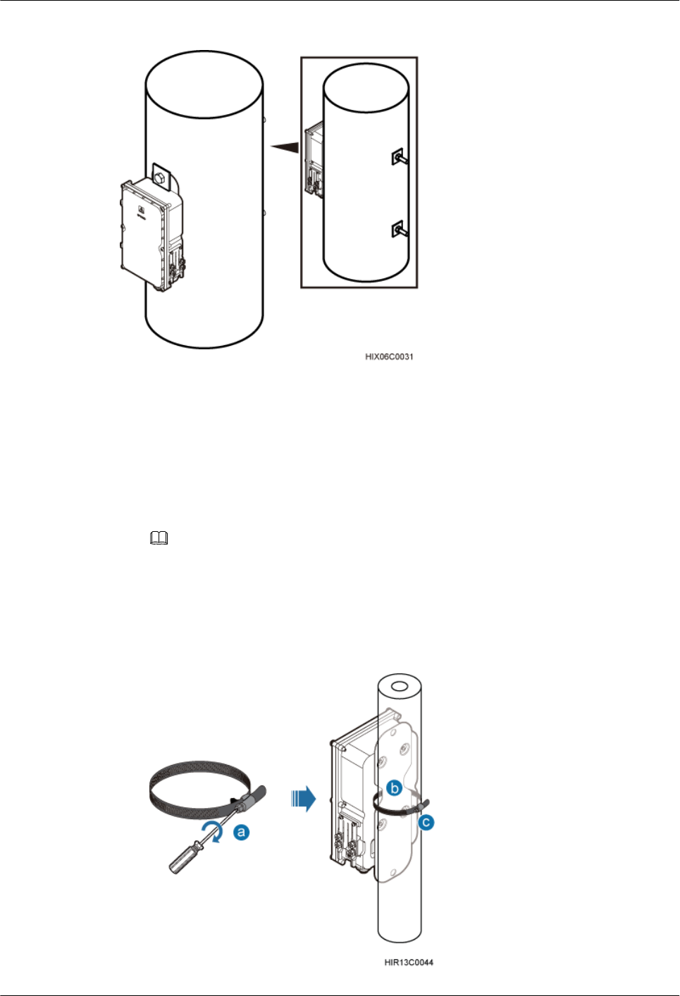
Figure 8-9 AC surge protection box installed on a wood pole
8.3 Installing an AC Surge Protection Box
This section describes the procedure for installing an AC surge protection box.
Procedure
lInstall an AC surge protection box on a pole, as shown in Figure 8-10.
NOTE
lWhen the diameter of the pole ranges from 60 mm to 114 mm (2.36 in. to 4.49 in.), the hose clamps
delivered with the AC surge protection box is used.
lWhen the diameter of the pole ranges from 114 mm to 400 mm (4.49 in. to 15.75 in.), the hose clamps
purchased locally is used.
Figure 8-10 Installing the AC surge protection box on a pole
8 Installing an AC Surge Protection Box and Related Cables
BTS3902E WCDMA
Installation Guide
8-6 Huawei Proprietary and Confidential
Copyright © Huawei Technologies Co., Ltd.
Issue Draft A (2011-06-30)
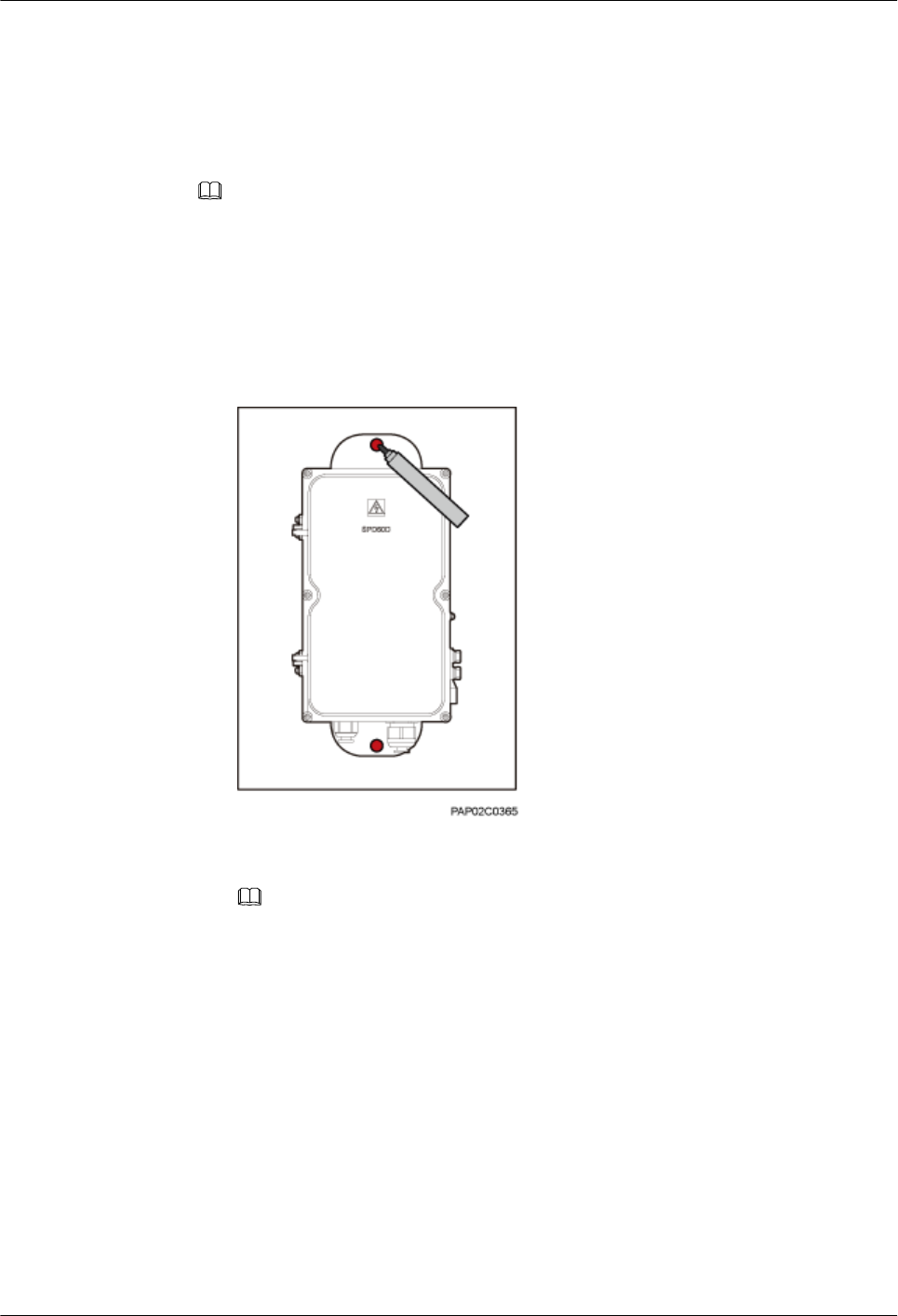
1. Loosen the hose clamp.
2. Lead the clamp through the gap between the rear mounting plate and the case of the
AC surge protection box.
3. Install the hose clamp around the pole, and secure the clamp.
NOTE
If the diameter of the pole around which the clamp is installed is small, cut the extra part of the clamp.
lInstall an AC surge protection box on a wall.
1. Place the rear mounting plate of the AC surge protection box against the wall, use a
level to verify that the plate is horizontal, and then mark anchor points using a marker,
as shown in Figure 8-11.
Figure 8-11 Marking the anchor points
2. Use a hammer drill with a Ø14 bit to drill holes at the anchor points, and install
expansion bolts, as shown in Figure 8-12.
NOTE
After disassembling the expansion bolt assemblies, discard the plastic tubes.
BTS3902E WCDMA
Installation Guide 8 Installing an AC Surge Protection Box and Related Cables
Issue Draft A (2011-06-30) Huawei Proprietary and Confidential
Copyright © Huawei Technologies Co., Ltd.
8-7

Figure 8-12 Installing an expansion bolt
(1) M10x65 bolt (2) Spring washer 10 (3) Plastic tube (4) Flat washer 10 (5) Expansion tube
3. Align the AC surge protection box with the holes in the wall, and tighten the expansion
bolts to 30 N·m (265.52 lbf·in.), as shown in Figure 8-13.
Figure 8-13 Installing an AC surge protection box
lInstall an AC surge protection box on a wood pole.
8 Installing an AC Surge Protection Box and Related Cables
BTS3902E WCDMA
Installation Guide
8-8 Huawei Proprietary and Confidential
Copyright © Huawei Technologies Co., Ltd.
Issue Draft A (2011-06-30)

1. Place the rear mounting plate of the AC surge protection box against the wood pole,
determine the anchor points on the middle axis, and then mark the anchor points.
2. Drill holes with the diameter of 12 mm (0.47 in.) at the anchor points through the
wood pole, as shown in Figure 8-14.
Figure 8-14 Drilling holes
3. Align the AC surge protection box with the holes in the wood pole, lead the two long
M10 bolts with spacers through the two mounting holes and holes, and then install the
bolts on the wood pole, as shown in Figure 8-15.
BTS3902E WCDMA
Installation Guide 8 Installing an AC Surge Protection Box and Related Cables
Issue Draft A (2011-06-30) Huawei Proprietary and Confidential
Copyright © Huawei Technologies Co., Ltd.
8-9
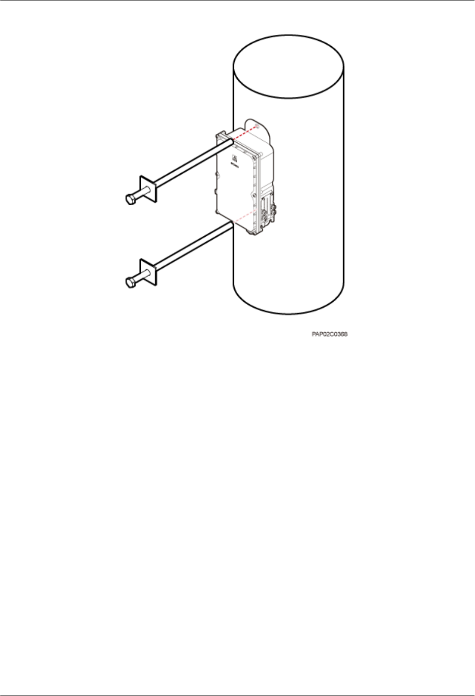
Figure 8-15 Installing the AC surge protection box on the wood pole
4. Tighten the nuts to 30 N·m (265.52 lbf·in.), as shown in Figure 8-16.
8 Installing an AC Surge Protection Box and Related Cables
BTS3902E WCDMA
Installation Guide
8-10 Huawei Proprietary and Confidential
Copyright © Huawei Technologies Co., Ltd.
Issue Draft A (2011-06-30)

Figure 8-16 Tightening the nuts
(1) Nut
----End
8.4 Installing Cables for an AC Surge Protection Box
This section describes the procedure for installing cables for an AC surge protection box.
Prerequisite
Add OT terminals to the power cables for the AC surge protection box on the surge protection
box side. For details, see Adding OT Terminals to the Power Cable Connected to the AC Surge
Protection Box.
Procedure
Step 1 Loosen the screws on the AC surge protection box using the M4 Phillips screwdriver and open
the cover plate. Then, remove the thread-lock sealing nut from the PG connector of the surge
protection box, and store waterproof blocks properly, as shown in Figure 8-17.
BTS3902E WCDMA
Installation Guide 8 Installing an AC Surge Protection Box and Related Cables
Issue Draft A (2011-06-30) Huawei Proprietary and Confidential
Copyright © Huawei Technologies Co., Ltd.
8-11

Figure 8-17 Opening the cover plate of the AC surge protection box
(1) PG connector (2) Thread-lock sealing nut of the PG connector (3) Waterproof block
NOTE
Do not use the removed thread-lock sealing nut of the PG connector with the thread-lock sealing nuts on
other surge protection boxes.
Step 2 Glide the thread-lock sealing nut and then the PG connector over the power cable.
Step 3 Connect the power cables to the AC surge protection box, as shown in Figure 8-18. The power
cable on the left connects the BTS3902E and the AC surge protection box, and the power cable
on the right connects the AC surge protection box and the external power device.
Figure 8-18 Cable connections of the AC surge protection box
(1) Power cable between the BTS3902E
and the AC surge protection box
(2) Power cable between the AC surge
protection box and the external power
device
(3) Clip (4) Insulation layer
8 Installing an AC Surge Protection Box and Related Cables
BTS3902E WCDMA
Installation Guide
8-12 Huawei Proprietary and Confidential
Copyright © Huawei Technologies Co., Ltd.
Issue Draft A (2011-06-30)

1. Lead the power cable between the surge protection box and the external power device
through the PG connector labeled IN. Connect the OT terminals of the brown, blue, and
yellow/green core wires to the Lin, Nin, and GND ports on the surge protection box
respectively.
2. Route the power cable between the BTS3902E and the AC surge protection box through
the PG connector labeled OUT. Connect the OT terminals of the blue, brown, and green
and yellow wires to the Nout, Lout, and GND ports in the AC surge protection box,
respectively.
3. Tighten the thread-lock sealing nut, and then use a wrench to tighten the PG connector to
ensure it is waterproofed properly.
Step 4 Fasten the power cables using clips.
NOTE
Ensure that the insulation layer of each power cable is fastened using clips.
Step 5 Close the cover plate of the surge protection box and tighten the screw to 1.4 N·m (123.91 lbf.in.)
using an M4 Phillips screwdriver, as shown in Figure 8-19.
Figure 8-19 Closing the cover plate of the AC surge protection box
Step 6 Wrap the joints of the corrugated pipe and power cables using waterproof tape and polyvinyl
chloride (PVC) insulation tape, as shown in Figure 8-20. Wrap the joints using waterproof tape
before using PVC insulation tape.
TIP
Wrap each connector with three layers of waterproof tape, from bottom up, then from top down, and finally
from bottom up. Do not cut the tape until all the three layers of the tape are already wrapped. When wrapping
tape, be sure that each layer of tape overlaps more than 50% of the preceding layer.
BTS3902E WCDMA
Installation Guide 8 Installing an AC Surge Protection Box and Related Cables
Issue Draft A (2011-06-30) Huawei Proprietary and Confidential
Copyright © Huawei Technologies Co., Ltd.
8-13
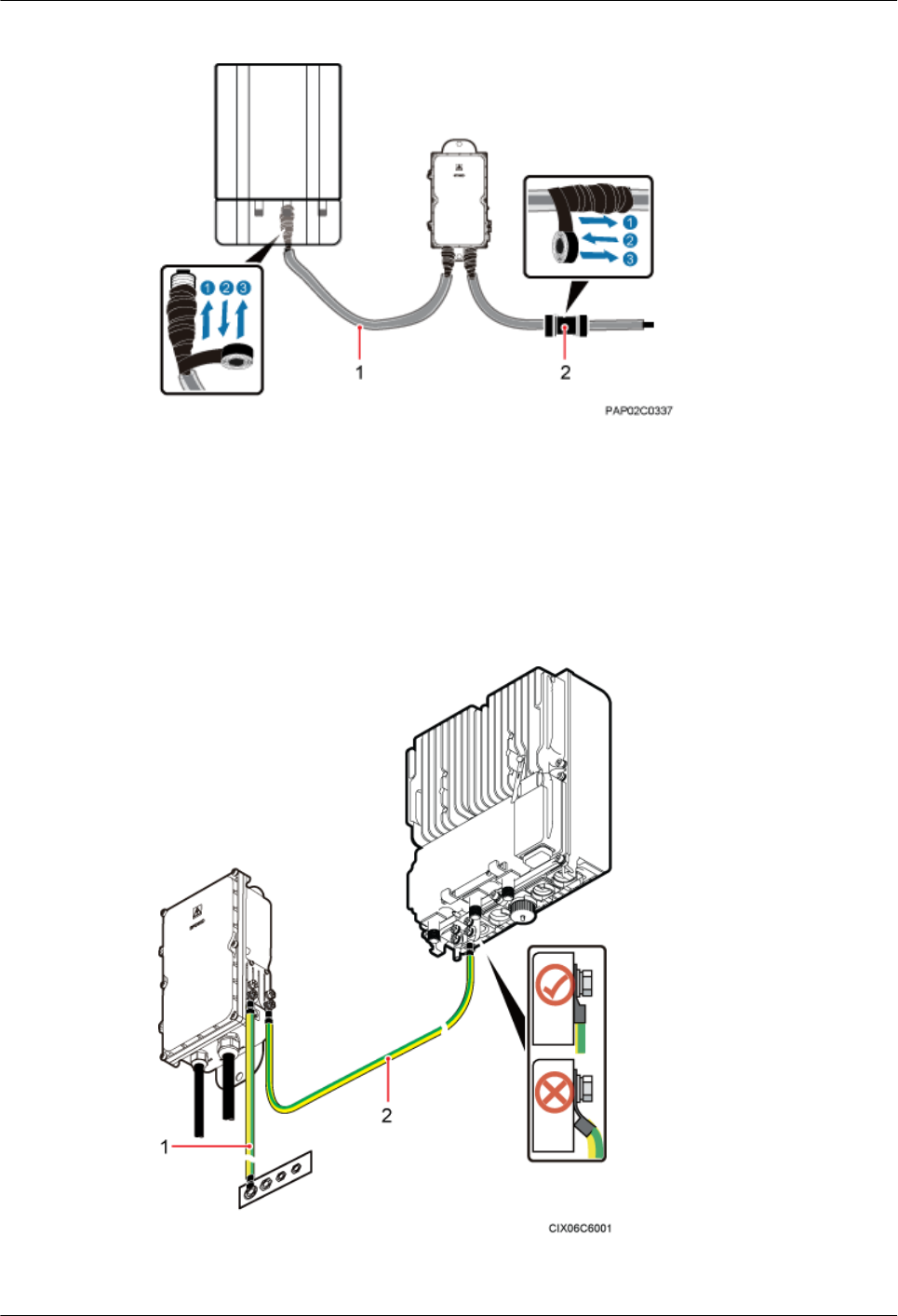
Figure 8-20 Securing AC power cables
(1) Corrugated pipe (2) Connector between corrugated pipes
Step 7 Bind the cables using cable ties at equal spacing of 30 cm (11.81 in.) and verify that the bend
radius of the corrugated pipe is not less than 60 mm (2.36 in.).
Step 8 Install the PGND cable and equipotential cable, as shown in Figure 8-21.
Figure 8-21 Installing the PGND cable and equipotential cable
(1) PGND cable (2) Equipotential cable
8 Installing an AC Surge Protection Box and Related Cables
BTS3902E WCDMA
Installation Guide
8-14 Huawei Proprietary and Confidential
Copyright © Huawei Technologies Co., Ltd.
Issue Draft A (2011-06-30)

----End
BTS3902E WCDMA
Installation Guide 8 Installing an AC Surge Protection Box and Related Cables
Issue Draft A (2011-06-30) Huawei Proprietary and Confidential
Copyright © Huawei Technologies Co., Ltd.
8-15

9 Installing Cables
About This Chapter
This chapter describes the procedure and precautions for installing the PGND cables, power
cables, and transmission cables for a BTS3902E in various scenarios. Based on actual
requirements, and it also describes how to install an optional monitoring signal cable as required.
9.1 Cabling Requirements
Cables must be routed according to the specified cabling requirements to prevent signal
interference.
9.2 Cable Connections
The cable connections of the BTS3902E vary depending on the number of BTS3902Es and the
BTS3902E port.
9.3 Installing a PGND Cable and Equipotential Cable
The protection ground (PGND) cable and equipotential cable must be installed based on actual
requirements.
9.4 Installing a BTS3902E Power Cable
A BTS3902E power cable connects the BTS3902E to an external power device, feeding external
power into the BTS3902E.
9.5 (Optional) Installing a BTS3902E RF Jumper
You must install a radio frequency (RF) jumper when a BTS3902E uses an external antenna.
9.6 Installing Transmission Cables
When a BTS3902E is installed outdoors, a fast Ethernet or gigabit Ethernet (FE/GE) cable or
FE/GE fiber optic cable must be installed based on actual requirements.
9.7 Installing the Housing
This chapter describes the procedures for installing the upper housing and optional camouflage
shell for a BTS3902E after the BTS3902E and related cables are installed.
9.8 Checking the BTS3902E Hardware Installation
This chapter describes how to check the hardware installation after a BTS3902E is installed.
9.9 Performing a Power-On Check on the BTS3902E
This chapter describes the procedure for performing a power-on check on the BTS3902E.
9.10 Appendix
BTS3902E WCDMA
Installation Guide 9 Installing Cables
Issue Draft A (2011-06-30) Huawei Proprietary and Confidential
Copyright © Huawei Technologies Co., Ltd.
9-1

This section describes the procedure for adding an easy power receptacle (pressfit type)
connector.This section describes the procedure for adding OT terminals.This section describes
the procedure for adding OT terminals to the surge protection box side of the power cable for
the AC surge protection box.
9 Installing Cables
BTS3902E WCDMA
Installation Guide
9-2 Huawei Proprietary and Confidential
Copyright © Huawei Technologies Co., Ltd.
Issue Draft A (2011-06-30)

9.1 Cabling Requirements
Cables must be routed according to the specified cabling requirements to prevent signal
interference.
NOTE
If a cable listed below is not required, skip the routing requirements of the cable.
General Cabling Requirements
The bending radius of the cables must meet the following specifications:
lThe bending radius of the 7/8'' feeder must be more than 250 mm (9.84 in.), and the bending
radius of the 5/4'' feeder must be more than 380 mm (14.96 in.).
lThe bending radius of the 1/4'' jumper must be more than 35 mm (1.38 in.). The bending
radius of the super-flexible 1/2'' jumper must be more than 50 mm (1.97 in.), and the bending
radius of the ordinary 1/2'' jumper must be more than 127 mm (5 in.).
lThe bending radius of the power cable or PGND cable must be at least five times the
diameter of the cable.
lThe bending radius of an fiber optic cable is at least 20 times the diameter of the fiber optic
cable.
lThe bending radius of the signal cable must be at least five times the diameter of the cable.
The cables must be bound as follows:
lThe cables must be bound tightly and neatly. The sheaths of the cables must not be damaged.
lThe cable ties must face the same direction, and those at the same horizontal line must be
in a straight line. Extra length of cable ties must be cut.
lLabels or nameplates must be attached to the cables after they are installed.
The cables must be routed as follows:
lDifferent types of cables must be installed in an untangled and orderly fashion.
lDifferent types of cables must be routed in parallel or separated by special objects.
Special Cabling Requirements
Cabling requirements for power cables are as follows:
lMultiple power cables must be bound when routed.
lPower cables must be installed in the position specified in engineering design documents.
lIf the length of power cables is insufficient, replace the cables rather than adding connectors
or soldering joints to lengthen the cables.
Cabling requirements for PGND cables are as follows:
lPGND cables for the base station must be connected to the same ground bar.
lPGND cables must be buried in the ground or routed indoors. They should not be routed
overhead before they are led into the equipment room.
lThe exterior of the coaxial wire and the shield layer of the shielded cable must have proper
electrical contact with the metal surface of the equipment to which they are connected.
BTS3902E WCDMA
Installation Guide 9 Installing Cables
Issue Draft A (2011-06-30) Huawei Proprietary and Confidential
Copyright © Huawei Technologies Co., Ltd.
9-3

lPGND cables and signal cables must be installed in an untangled and orderly fashion. A
certain distance must be reserved between them to prevent interference from each other.
lFuses or switches must not be installed on the PGND cables.
lOther devices must not be used for electrical connections of the PGND cables.
lAll the metal parts in the housing of the equipment must be reliably connected to the ground
terminal.
Cabling requirements for fiber optic cables are as follows:
lDo not stretch, step on, or place heavy objects on fiber optic cables. Keep the cables away
from sharp objects.
lWhen fiber optic cables are routed, the extra length of the cables must be coiled around
special devices, such as a fiber coiler.
lWhen coiling fiber optic cables, apply even strength. Do not bend the cables with force.
lVacant optical connectors must be covered with dustproof caps.
9.2 Cable Connections
The cable connections of the BTS3902E vary depending on the number of BTS3902Es and the
BTS3902E port.
Cable Connections of the BTS3902E
Figure 9-1 shows the cable connections of a single BTS3902E implementing transmission over
an electrical port.
9 Installing Cables
BTS3902E WCDMA
Installation Guide
9-4 Huawei Proprietary and Confidential
Copyright © Huawei Technologies Co., Ltd.
Issue Draft A (2011-06-30)

Figure 9-1 Cable connections of a single BTS3902E implementing transmission over an
electrical port
(1) BTS3902E power cable (2) PGND cable (optional) (3) Equipotential cable (optional)
(4) Fast Ethernet or gigabit Ethernet
(FE/GE) cable
(5) BTS3902E monitoring signal
cable (optional)
—
Figure 9-2 shows the cable connections of a single BTS3902E implementing transmission over
an optical port.
BTS3902E WCDMA
Installation Guide 9 Installing Cables
Issue Draft A (2011-06-30) Huawei Proprietary and Confidential
Copyright © Huawei Technologies Co., Ltd.
9-5

Figure 9-2 Cable connections of a single BTS3902E implementing transmission over an optical
port
(1) BTS3902E power cable (2) PGND cable (optional) (3) Equipotential cable (optional)
(4) FE/GE fiber optic cable (5) BTS3902E monitoring signal
cable (optional)
—
Figure 9-3 shows the cable connections of a single BTS3902E implementing power over
Ethernet (POE) over an electrical port and transmission using a fiber optic cable.
9 Installing Cables
BTS3902E WCDMA
Installation Guide
9-6 Huawei Proprietary and Confidential
Copyright © Huawei Technologies Co., Ltd.
Issue Draft A (2011-06-30)
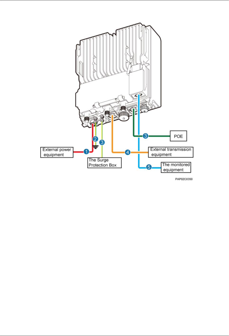
Figure 9-3 Cable connections of a single BTS3902E implementing POE over an electrical port
and transmission using a fiber optic cable
(1) BTS3902E power cable (2) PGND cable (optional) (3) Equipotential cable (optional)
(4) FE/GE cable (5) FE/GE fiber optic cable (6) BTS3902E monitoring signal cable
(optional)
Figure 9-4 shows the cable connections of two BTS3902Es implementing transmission and
cascading using fiber optic cables.
BTS3902E WCDMA
Installation Guide 9 Installing Cables
Issue Draft A (2011-06-30) Huawei Proprietary and Confidential
Copyright © Huawei Technologies Co., Ltd.
9-7

Figure 9-4 Cable connections of two BTS3902Es implementing transmission and cascading
using fiber optic cables
(1) BTS3902E power cable (2) PGND cable (optional) (3) Equipotential cable (optional)
(4) FE/GE fiber optic cable (5) BTS3902E monitoring signal
cable (optional)
(6) FE/GE fiber optic cable for
cascading
9.3 Installing a PGND Cable and Equipotential Cable
The protection ground (PGND) cable and equipotential cable must be installed based on actual
requirements.
Context
Table 9-1 lists the specifications of the PGND cable and equipotential cable.
Table 9-1 Specifications of the BTS3902E PGND cable and equipotential cable
Cable One End The Other End Remarks
PGND cable OT terminal (M6, 16
mm2 [0.025 in.2])
OT terminal (M6, 16
mm2 [0.025 in.2])
Green and yellow
9 Installing Cables
BTS3902E WCDMA
Installation Guide
9-8 Huawei Proprietary and Confidential
Copyright © Huawei Technologies Co., Ltd.
Issue Draft A (2011-06-30)

Cable One End The Other End Remarks
Equipotential cable OT terminal (M6, 16
mm2 [0.025 in.2])
OT terminal (M6, 16
mm2 [0.025 in.2])
Green and yellow
Procedure
lInstall the PGND cable when no AC surge protection box is installed, as shown in Figure
9-5.
1. Connect one end of the BTS3902E PGND terminal to the ground cable on the
BTS3902E and the other end to the external ground bar.
Figure 9-5 Installing the BTS3902E PGND cable
NOTE
When installing the PGND cable, tightly press the OT terminal in the correct direction, as
shown in Figure 9-6.
BTS3902E WCDMA
Installation Guide 9 Installing Cables
Issue Draft A (2011-06-30) Huawei Proprietary and Confidential
Copyright © Huawei Technologies Co., Ltd.
9-9
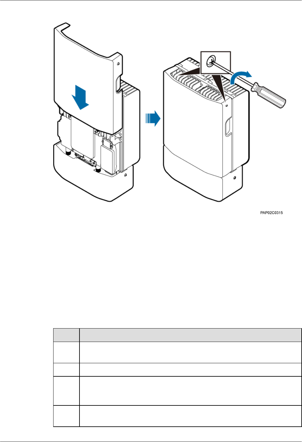
Figure 9-25 Closing the housing and tightening the screws
----End
9.8 Checking the BTS3902E Hardware Installation
This chapter describes how to check the hardware installation after a BTS3902E is installed.
Table 9-3 provides the checklist for the BTS3902E hardware installation.
Table 9-3 Checklist for the BTS3902E Hardware Installation
SN Item
1The position for each device conforms to the engineering drawing and meets the
space requirement. Sufficient space is reserved for equipment maintenance.
2 The BTS3902E is securely installed and the installed BTS3902E has a housing.
3 In the wall-mounted scenario, the holes of the mounting bracket are well aligned
with the holes of the expansion bolt assemblies. In addition, the adapting plates are
secured on the wall evenly and steadily.
4 In the pole-mounted scenario, the supports for the mounting brackets are secured
on the pole.
BTS3902E WCDMA
Installation Guide 9 Installing Cables
Issue Draft A (2011-06-30) Huawei Proprietary and Confidential
Copyright © Huawei Technologies Co., Ltd.
9-25
SN Item
5The horizontal error of the BTS3902E is less than 3 mm (0.12 in.), and the vertical
error is not more than 3 mm (0.12 in.).
6 The outdoor cables are properly installed. The vacant ports are covered with
waterproof caps, and the caps are waterproofed.
7 None of power cables and PGND cables is short-circuited or reversely connected.
In addition, these cables are not damaged or broken.
8 Power cables and PGND cables are separately bound from other cables.
9 All BTS3902E-related modules are connected to the closest ground bar using
PGND cables.
10 The connectors of each signal cable are intact and securely linked, and these cables
are not damaged or broken.
11 Labels are correct, legible, and complete at both ends of each cable, feeder, and
jumper.
Table 9-4 provides the checklist for the installation of an AC surge protection box.
Table 9-4 Checklist for the installation of an AC surge protection box
SN Item
1The PG connectors for routing cables on an AC surge protection box are securely
installed.
2 The waterproof fillers on an AC surge protection box are not stripped or broken.
3 OT terminals are securely linked to the cables connecting to an AC surge protection
box. Cable sheaths are not damaged, and the extra length of each cable is cut without
sharp edges.
4 PG connectors are tightened, and waterproof rings are secured.
5 The six screws on the cabling cavity for an AC surge protection box are tightened
properly.
6 The axis between the cover plate for and the case of an AC surge protection box is
not broken, and the surface of the protection box is not scratched.
7 The cable connections for an AC surge protection box meet the requirements in the
operation guide. The cover plate for the cabling cavity is closed after OT terminals
are tightened.
8 An AC surge protection box is powered off before installation and maintenance.
9 The protection grounding of an AC surge protection box and the surge protection
grounding of a building share one group of ground conductors.
10 An AC surge protection box must be installed or maintained in dry conditions.
9 Installing Cables
BTS3902E WCDMA
Installation Guide
9-26 Huawei Proprietary and Confidential
Copyright © Huawei Technologies Co., Ltd.
Issue Draft A (2011-06-30)
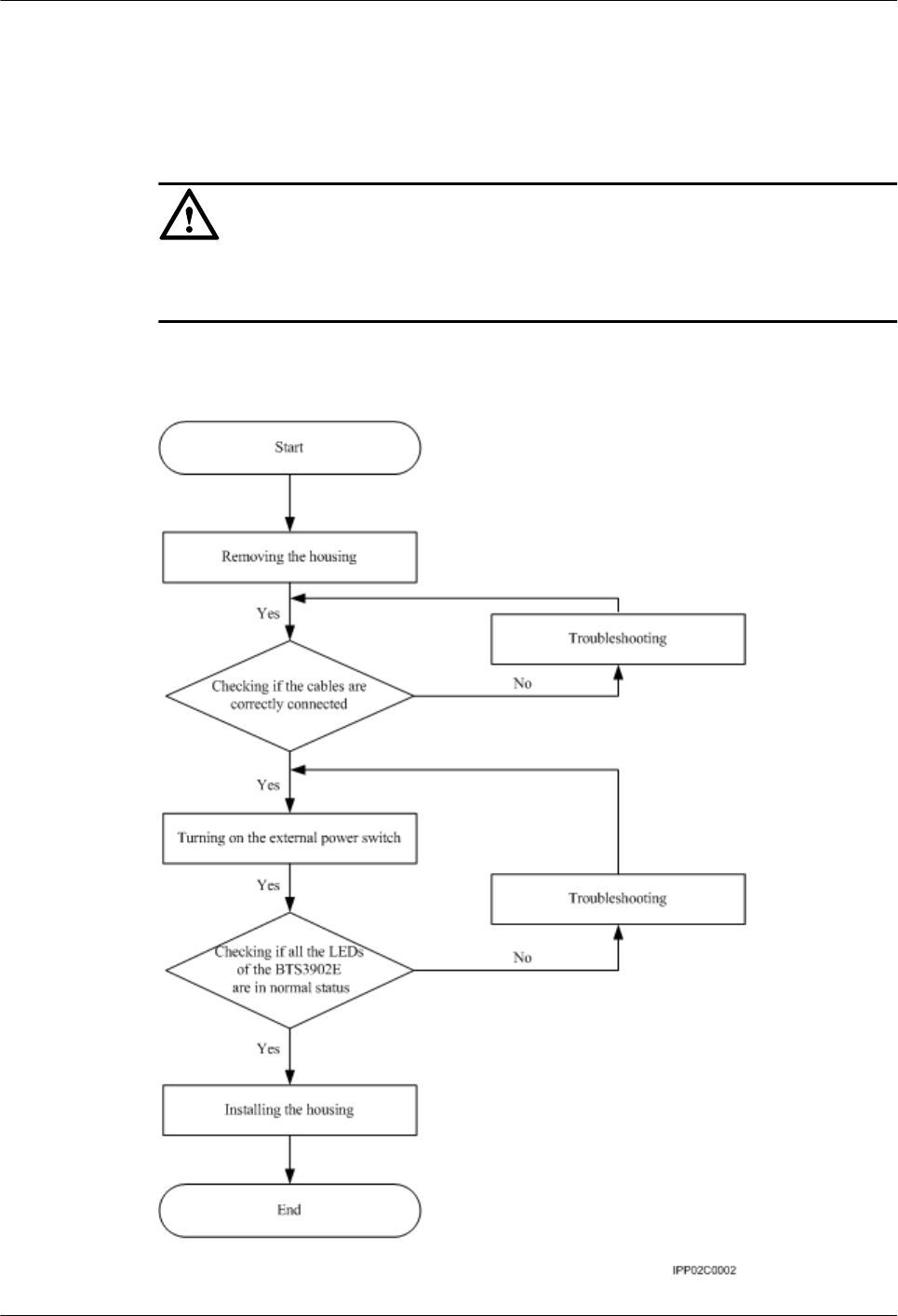
9.9 Performing a Power-On Check on the BTS3902E
This chapter describes the procedure for performing a power-on check on the BTS3902E.
CAUTION
After you unpack a BTS3902E, you must power it on within 24 hours. If you power off the
BTS3902E for maintenance, you must restore power to it within 24 hours.
Figure 9-26 shows the BTS3902E power-on check procedure.
Figure 9-26 BTS3902E power-on check procedure
BTS3902E WCDMA
Installation Guide 9 Installing Cables
Issue Draft A (2011-06-30) Huawei Proprietary and Confidential
Copyright © Huawei Technologies Co., Ltd.
9-27
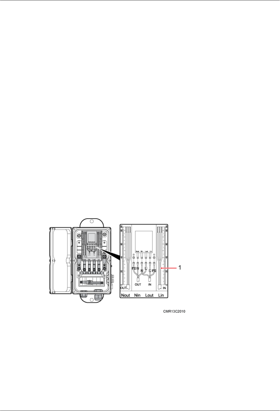
9.10 Appendix
This section describes the procedure for adding an easy power receptacle (pressfit type)
connector.This section describes the procedure for adding OT terminals.This section describes
the procedure for adding OT terminals to the surge protection box side of the power cable for
the AC surge protection box.
9.10.1 Adding OT Terminals to the Power Cable Connected to the AC Surge Protection Box
This section describes the procedure for adding OT terminals to the power cable connected to
the AC surge protection box.
9.10.2 Installing a Ground Clip
This section describes how to install a ground clip on a fast Ethernet or gigabit Ethernet (FE/
GE) cable.
9.10.1 Adding OT Terminals to the Power Cable Connected to the
AC Surge Protection Box
This section describes the procedure for adding OT terminals to the power cable connected to
the AC surge protection box.
Context
Figure 9-27 shows the cable diagram on labels.
Figure 9-27 Cable diagram on labels
(1) Cable diagram on labels
Procedure
Step 1 Cut the cable to the required length based on the actual cable route.
Step 2 If the power cable is longer than or equal to 5 m (16.4 ft.), cut the corrugated pipe into multiple
5-meter-long pieces; if the cable is shorter than 5 m (16.4 ft.), cut the corrugated pipe based on
the actual length of the power cable.
9 Installing Cables
BTS3902E WCDMA
Installation Guide
9-28 Huawei Proprietary and Confidential
Copyright © Huawei Technologies Co., Ltd.
Issue Draft A (2011-06-30)
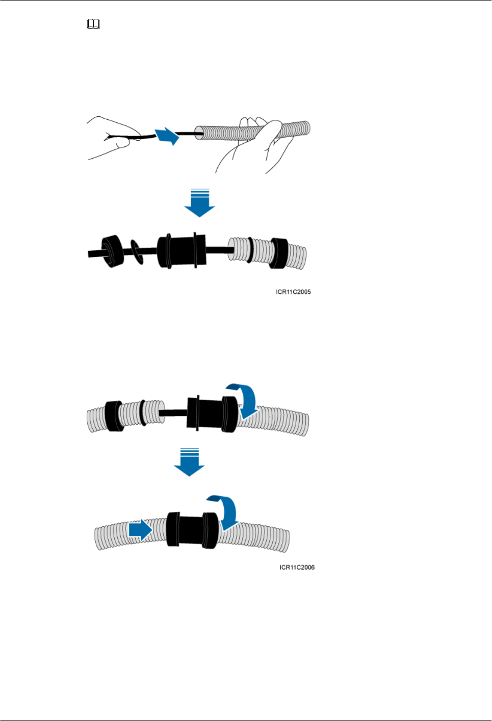
NOTE
Following is based on the power cable longer than or equal to 5 m (16.4 ft.).
Step 3 Lead the power cable through corrugated pipes, and add a connector between two corrugated
pipes, as shown in Figure 9-28.
Figure 9-28 Leading the power cable through corrugated pipes
Step 4 Join the corrugated pipes, as shown in Figure 9-29.
Figure 9-29 Joining corrugated pipes
Step 5 Determine the length of the power cable for different operations based on the labels, as shown
in Figure 9-30.
BTS3902E WCDMA
Installation Guide 9 Installing Cables
Issue Draft A (2011-06-30) Huawei Proprietary and Confidential
Copyright © Huawei Technologies Co., Ltd.
9-29
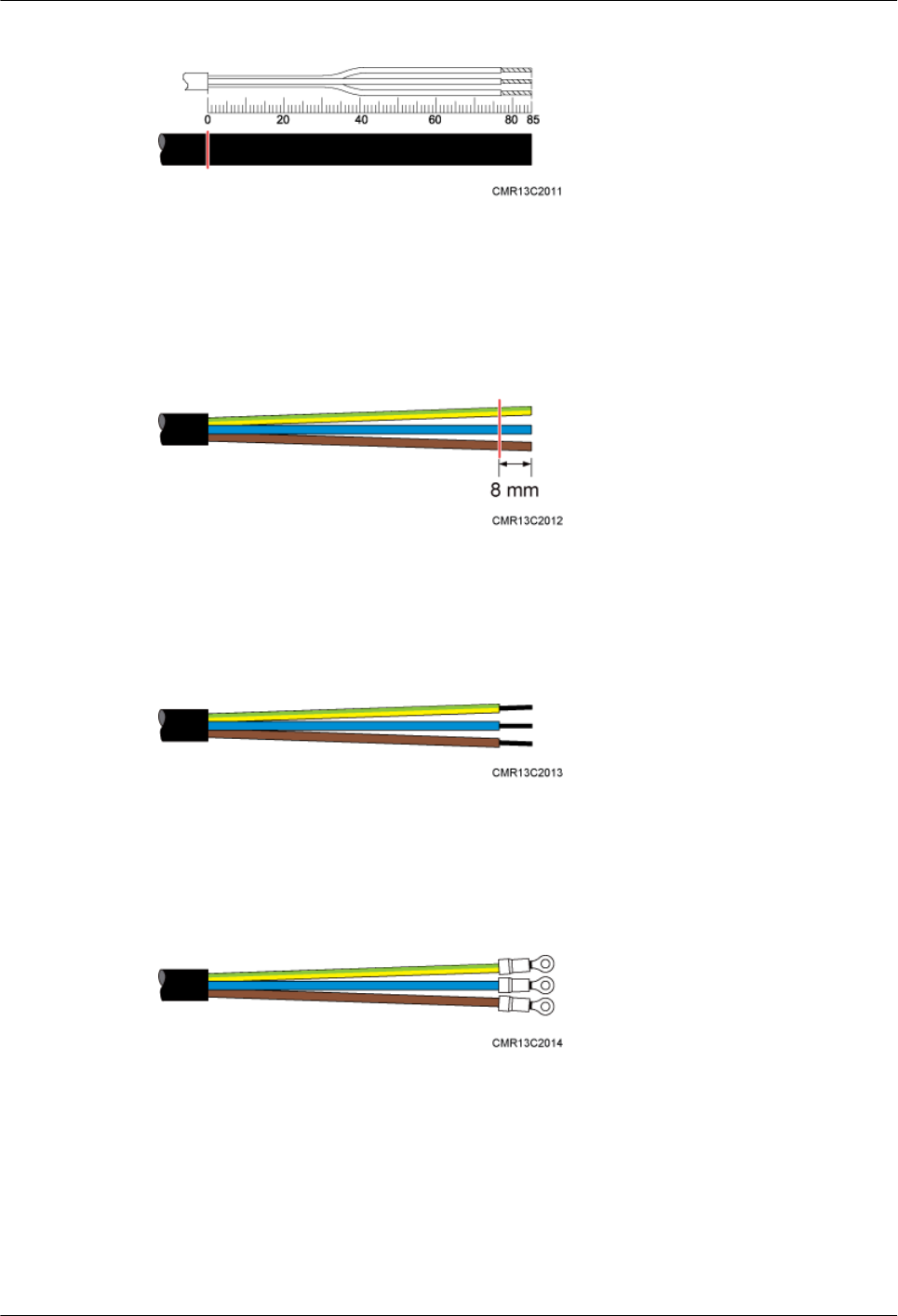
Figure 9-30 Determining the length of the power cable
Step 6 Use a utility knife to strip the specified length of the sheath and shield layer off the power cable,
as shown in Figure 9-31.
Figure 9-31 Stripping the specified length of the sheath and shield layer
Step 7 Strip the sheath off each core wire, as shown in Figure 9-32.
Figure 9-32 Stripping the sheath off each core wire
Step 8 Add OT terminals to the three core wires, as shown in Figure 9-33.
Figure 9-33 Adding OT terminals
----End
9.10.2 Installing a Ground Clip
This section describes how to install a ground clip on a fast Ethernet or gigabit Ethernet (FE/
GE) cable.
9 Installing Cables
BTS3902E WCDMA
Installation Guide
9-30 Huawei Proprietary and Confidential
Copyright © Huawei Technologies Co., Ltd.
Issue Draft A (2011-06-30)
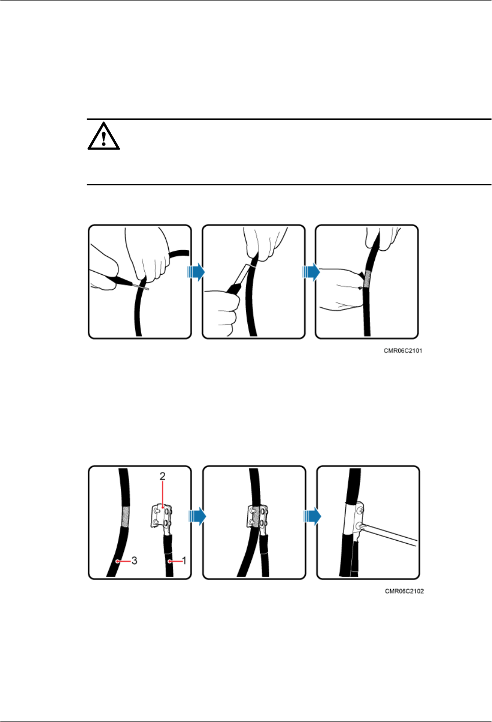
Procedure
Step 1 Determine the position for installing the ground clip on the cable based on the actual cable route.
Step 2 Use a utility knife to strip the sheath off the FE/GE cable for about 32 mm to expose the shield
layer, as shown in Figure 9-34.
CAUTION
Do not damage the shield layer when stripping the sheath off the cable.
Figure 9-34 Stripping the sheath off the FE/GE cable
Step 3 Install the ground clip on the shield layer of the cable, and then use a screwdriver to tighten the
screws on the ground clip, as shown in Figure 9-35.
Figure 9-35 Tightening the screws on a ground clip
(1) Ground cable (2) Ground clip (3) FE/GE cable
Step 4 Wrap three layers of waterproof tape and three layers of polyvinyl chloride (PVC) insulation
tape at the ground clip.
BTS3902E WCDMA
Installation Guide 9 Installing Cables
Issue Draft A (2011-06-30) Huawei Proprietary and Confidential
Copyright © Huawei Technologies Co., Ltd.
9-31
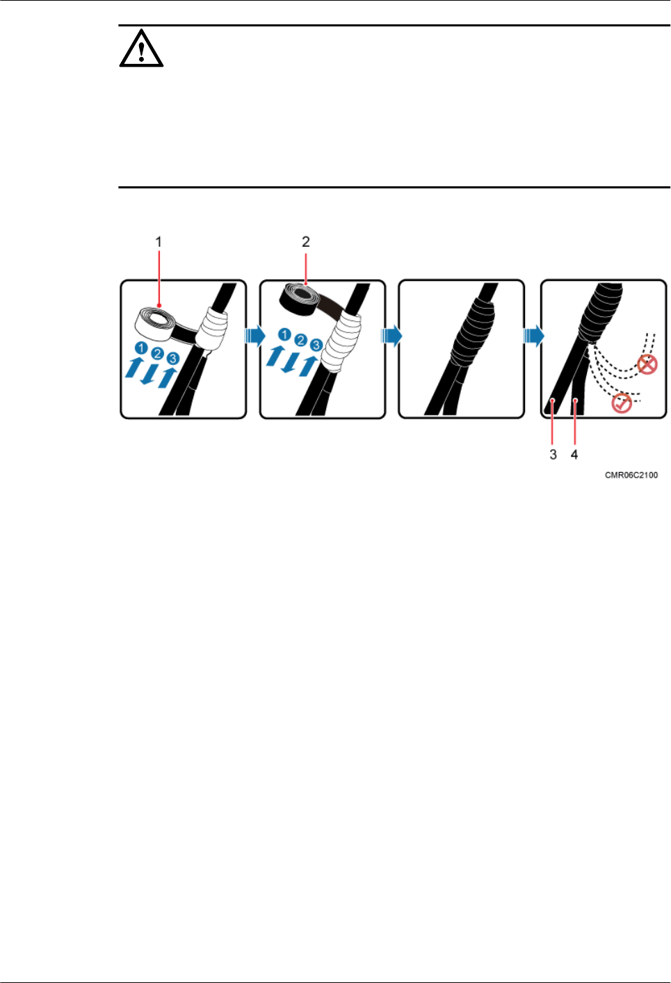
CAUTION
lWrap the tape around the clip from bottom up, then from top down, and finally from bottom
up. Do not cut the tape until all the three layers of the tape are already wrapped. When
wrapping tape, be sure that each layer of tape overlaps more than 50% of the preceding layer.
lThe degree between the ground cable and the FE/GE cable is not greater than 15°. When the
FE/GE cable is routed vertically, the ground cable must be routed downwards.
Figure 9-36 Wrapping waterproof tape and PVC insulation tape
(1) Waterproof tape (2) PVC insulation tape (3) FE/GE cable (4) Ground cable
Step 5 Connect the ground cable to an external ground bar.
----End
9 Installing Cables
BTS3902E WCDMA
Installation Guide
9-32 Huawei Proprietary and Confidential
Copyright © Huawei Technologies Co., Ltd.
Issue Draft A (2011-06-30)