Huawei Technologies BTS3902E-U850 Micro BTS User Manual Site Maintenance Guide
Huawei Technologies Co.,Ltd Micro BTS Site Maintenance Guide
UserManual.wiki
>
Huawei Technologies
>
BTS3902E-U850 User Manual
>
UserManual_part1.pdf
Contents
1.
UserManual_part1.pdf
2.
UserManual_part2.pdf
3.
UserManual_Safety Manual.pdf
UserManual_part1.pdf
Navigation menu
Upload a User Manual
Namespaces
Wiki Guide
HTML
PDF
Info
Views
User Manual
Discussion / Help
Navigation

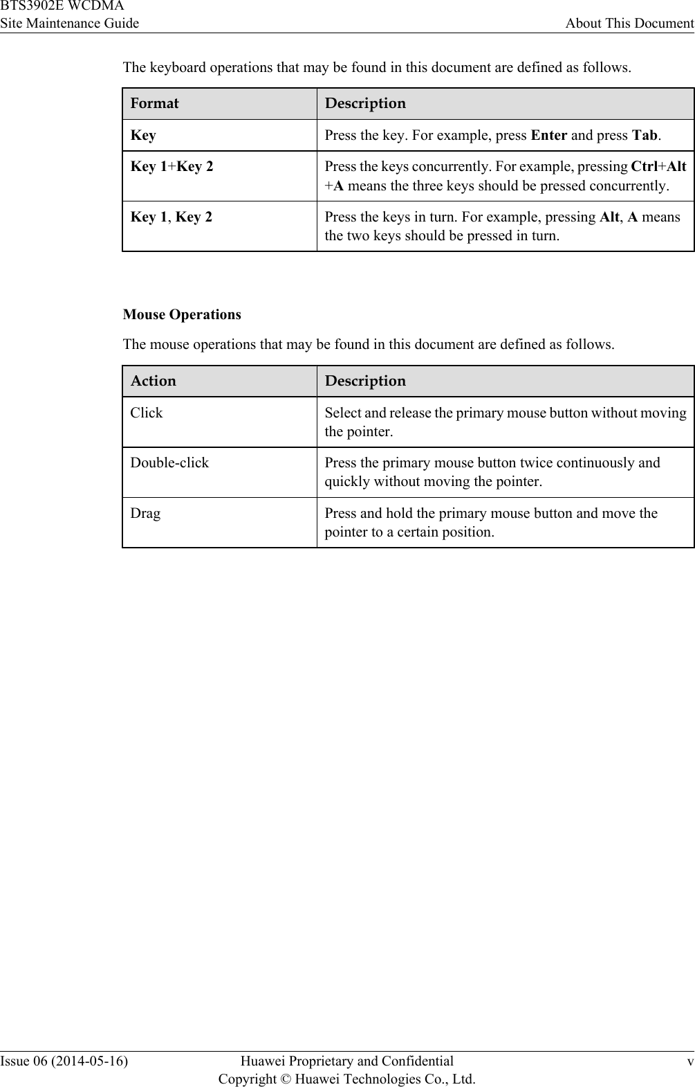
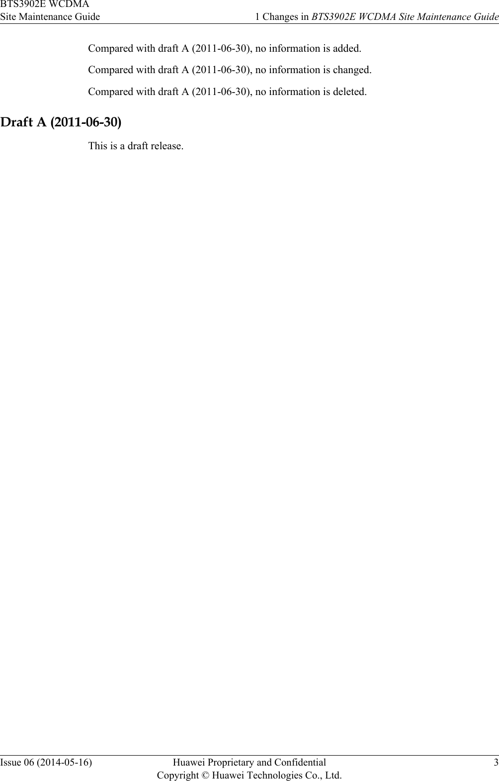
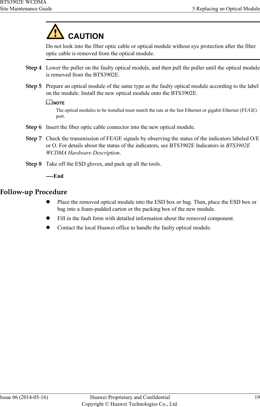
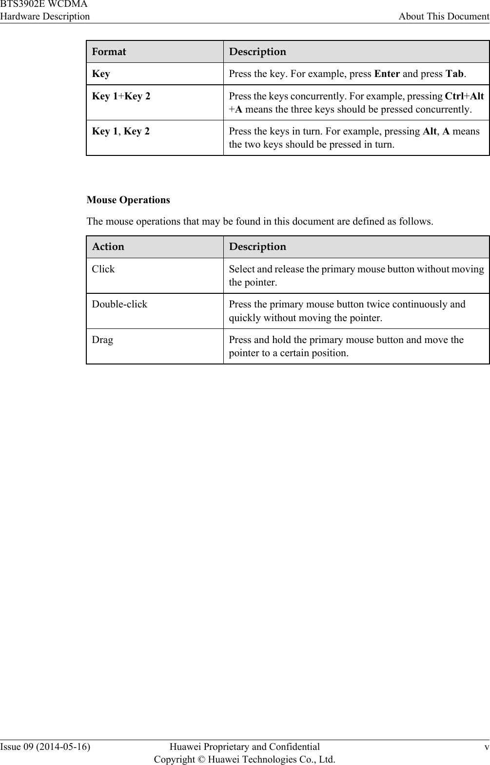
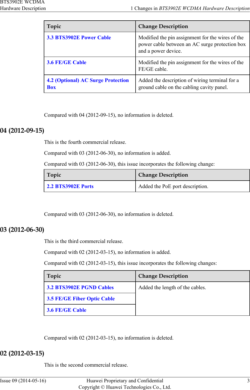
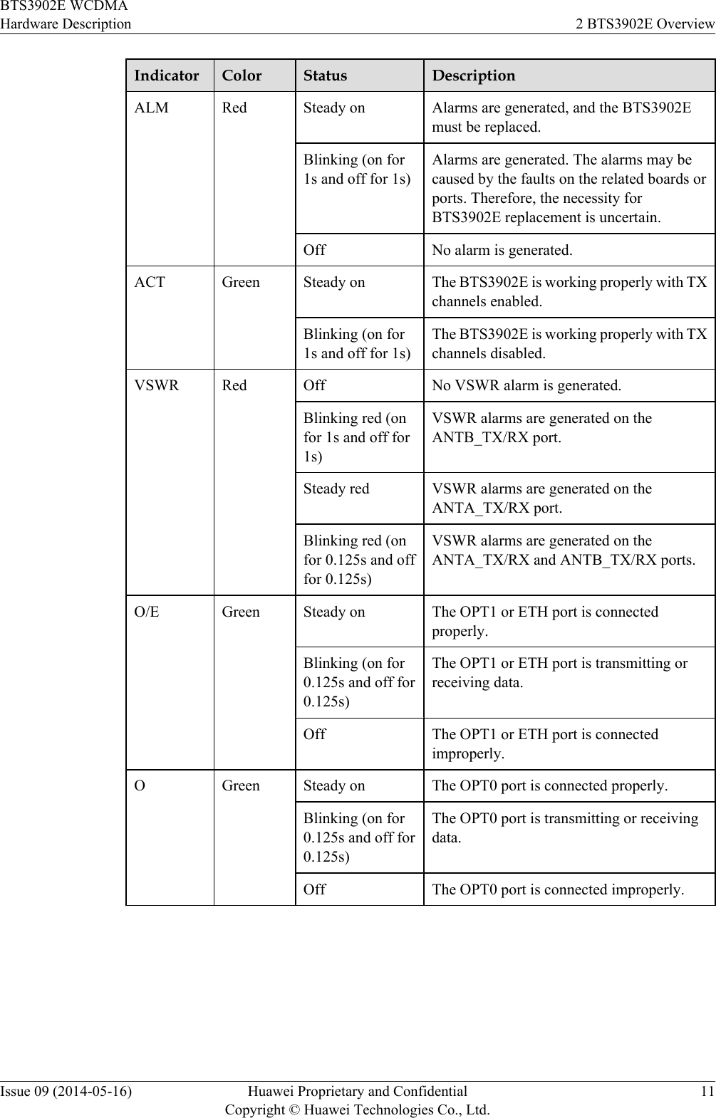
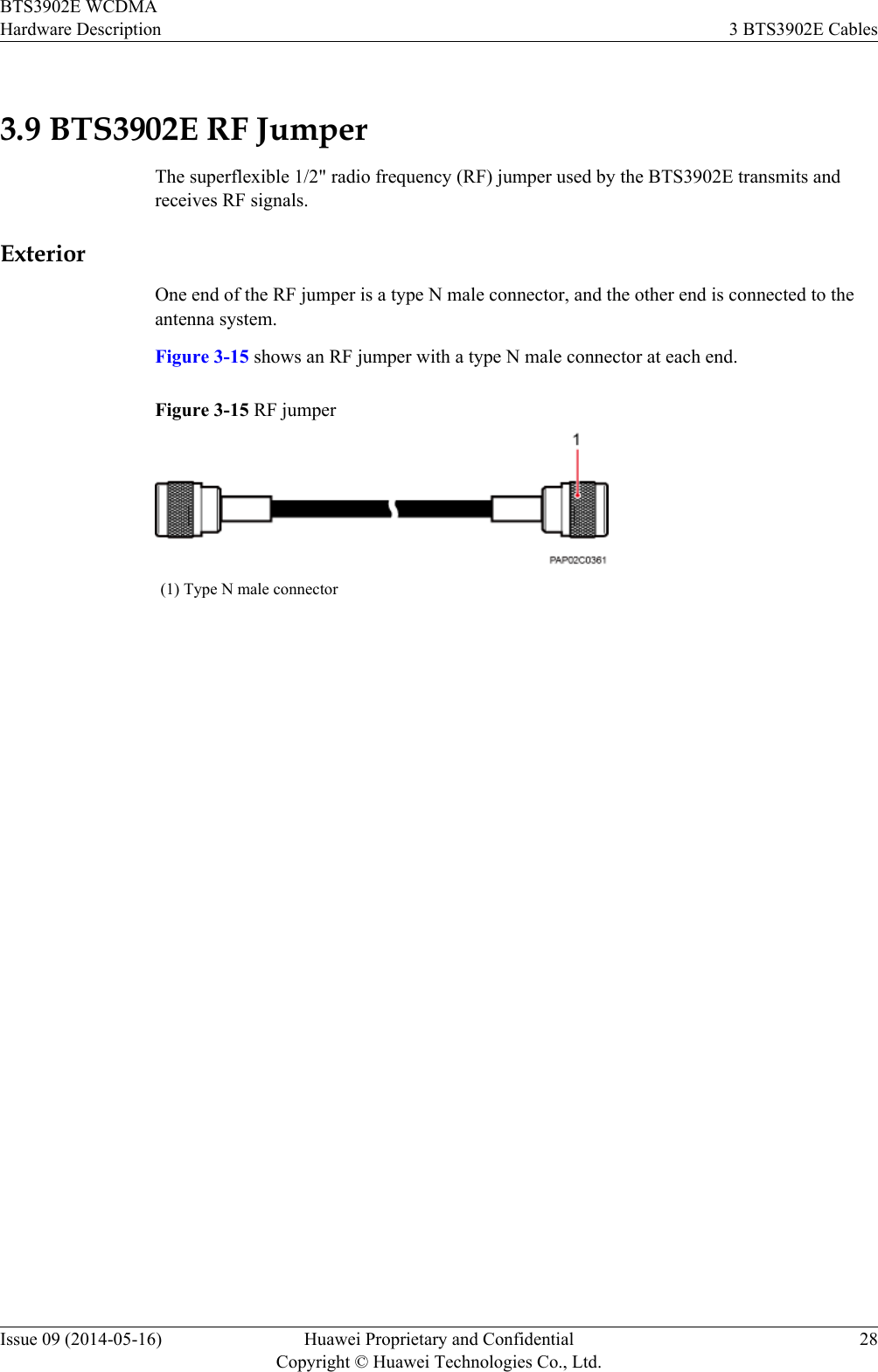
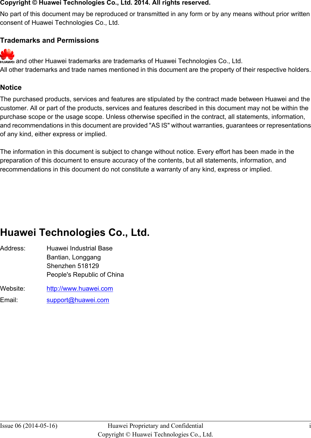
![Convention DescriptionItalic Book titles are in italics.Courier New Examples of information displayed on the screen are inCourier New. Command ConventionsThe command conventions that may be found in this document are defined as follows.Convention DescriptionBoldface The keywords of a command line are in boldface.Italic Command arguments are in italics.[ ] Items (keywords or arguments) in brackets [ ] are optional.{ x | y | ... } Optional items are grouped in braces and separated byvertical bars. One item is selected.[ x | y | ... ] Optional items are grouped in brackets and separated byvertical bars. One item is selected or no item is selected.{ x | y | ... }*Optional items are grouped in braces and separated byvertical bars. A minimum of one item or a maximum of allitems can be selected.[ x | y | ... ]*Optional items are grouped in brackets and separated byvertical bars. Several items or no item can be selected. GUI ConventionsThe GUI conventions that may be found in this document are defined as follows.Convention DescriptionBoldface Buttons, menus, parameters, tabs, window, and dialog titlesare in boldface. For example, click OK.>Multi-level menus are in boldface and separated by the ">"signs. For example, choose File > Create > Folder. Keyboard OperationsThe keyboard operations that may be found in this document are defined as follows.BTS3902E WCDMAHardware Description About This DocumentIssue 09 (2014-05-16) Huawei Proprietary and ConfidentialCopyright © Huawei Technologies Co., Ltd.iv](https://usermanual.wiki/Huawei-Technologies/BTS3902E-U850.UserManual-part1-pdf/User-Guide-2303954-Page-5.png)
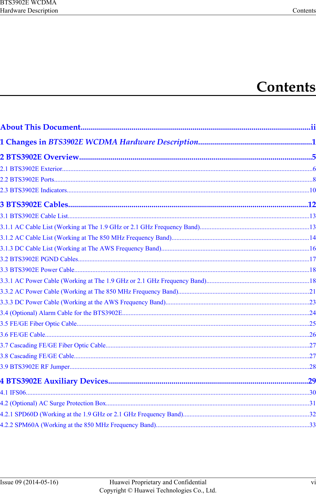
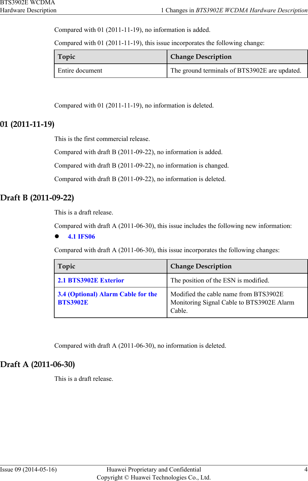
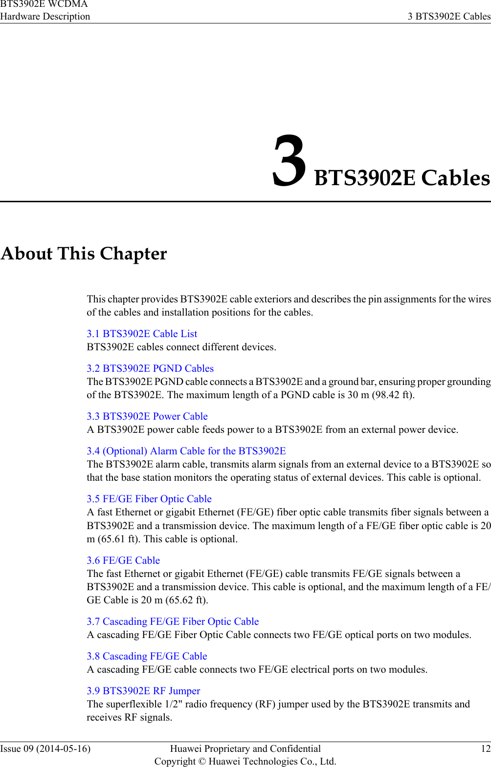
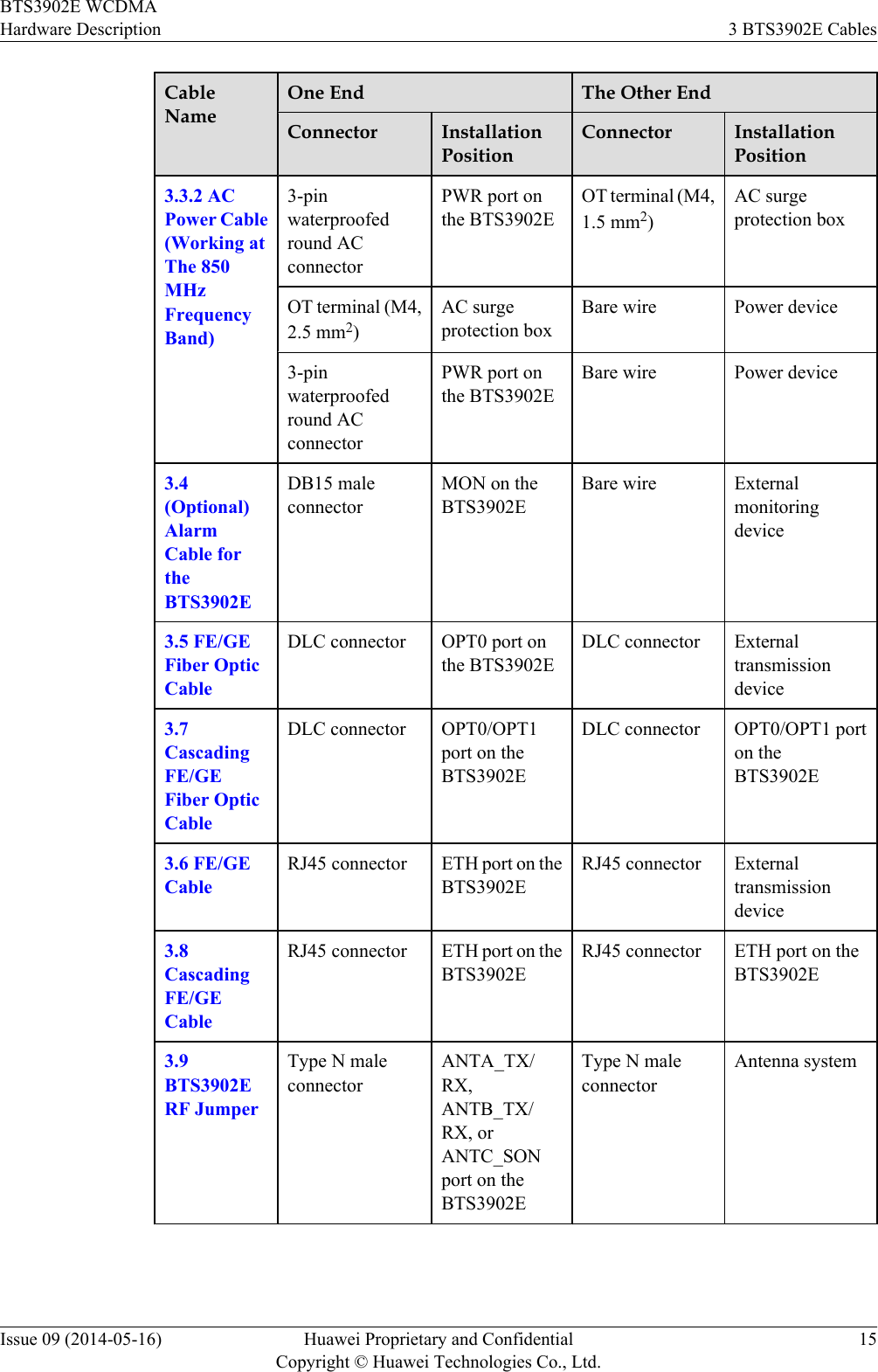
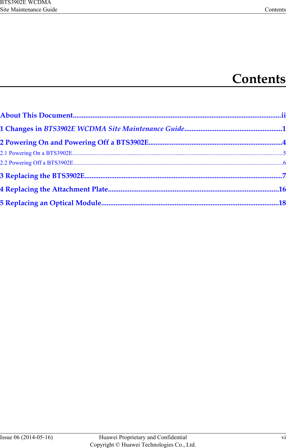
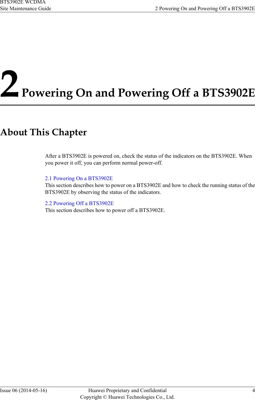
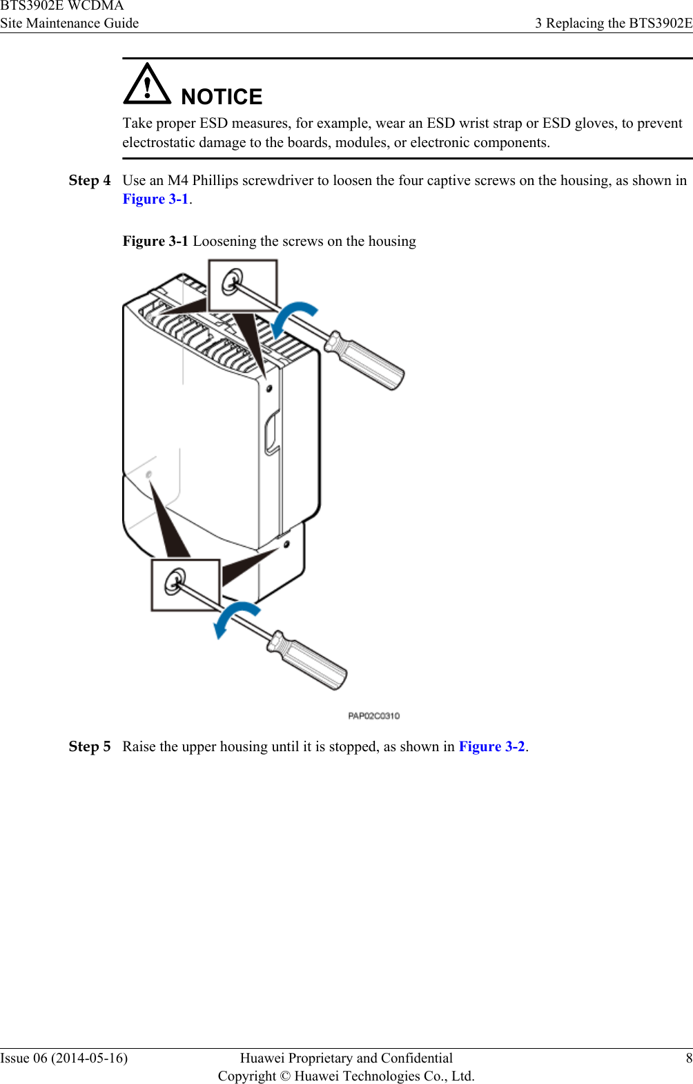
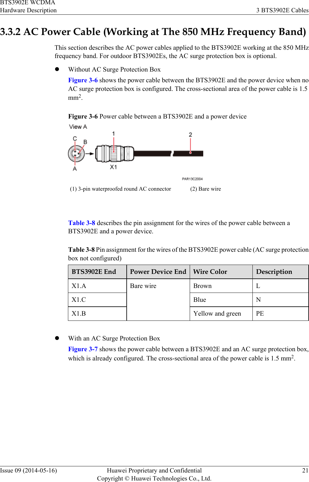
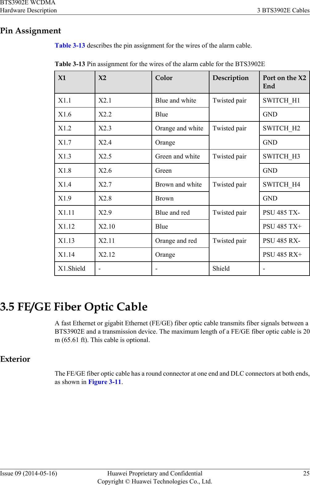
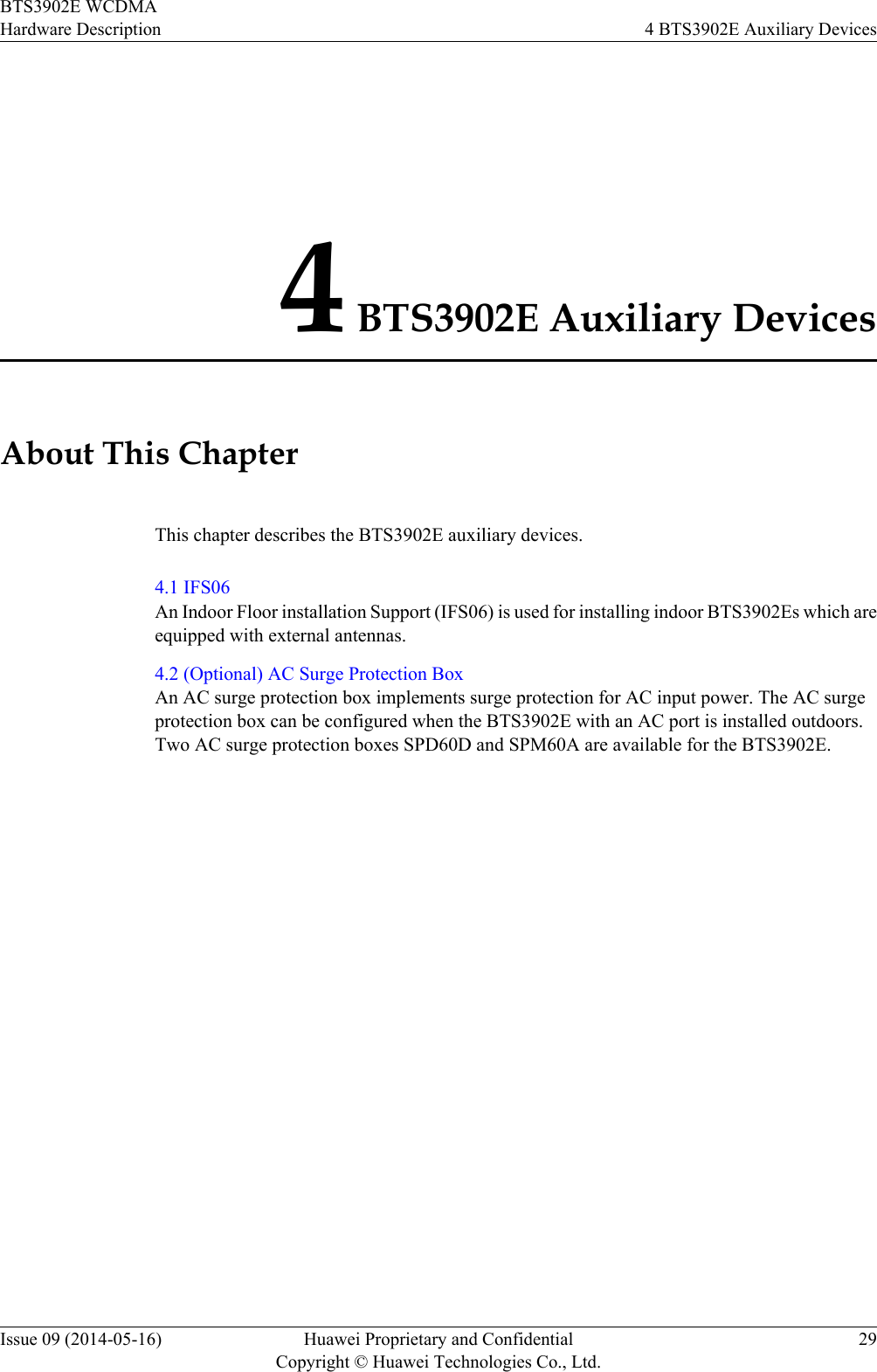
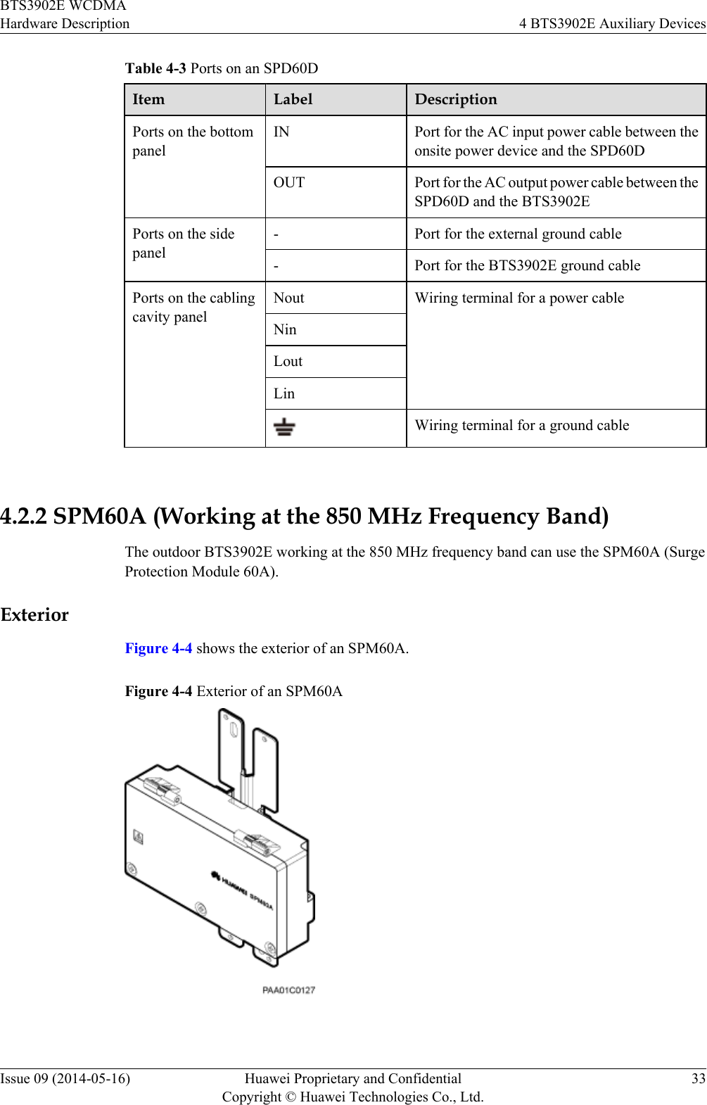
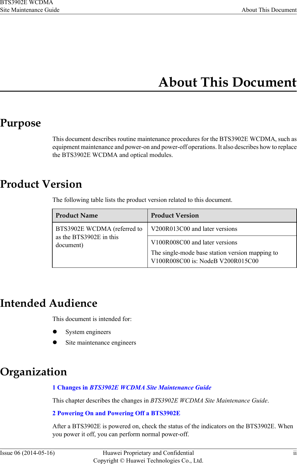
![Table 3-4 Specifications of PGND cablesCable Name Cross-SectionalAreaOne End The OtherEndCable ColorPGND cableused for the 1.9GHz, 2.1 GHzAWS frequencyband16 mm2 (0.025in.2)OT terminal(M6, 16 mm2[0.025 in.2])OT terminal(M6, 16 mm2[0.025 in.2])Yellow andgreenPGND cableused for the 850MHz frequencyband6 mm2 (0.025 in.2)OT terminal(M6, 6 mm2[0.025 in.2])OT terminal(M6, 6 mm2[0.025 in.2])Yellow andgreen OT terminals must be added to both ends of the PGND cable onsite. You can determine the colorof the cable and whether to use two-hole terminals in compliance with local regulations.Figure 3-2 shows a two-hole terminal.Figure 3-2 Two-hole terminal 3.3 BTS3902E Power CableA BTS3902E power cable feeds power to a BTS3902E from an external power device.3.3.1 AC Power Cable (Working at The 1.9 GHz or 2.1 GHzFrequency Band)This section describes the AC power cable applied to the BTS3902E working at the 1.9 GHz or2.1 GHz frequency band. For outdoor BTS3902Es, the AC surge protection box is optional.lWithout AC Surge Protection BoxFigure 3-3 shows the power cable between the BTS3902E and the power device when noAC surge protection box is configured. The cross-sectional area of the power cable is 1.5mm2.BTS3902E WCDMAHardware Description 3 BTS3902E CablesIssue 09 (2014-05-16) Huawei Proprietary and ConfidentialCopyright © Huawei Technologies Co., Ltd.18](https://usermanual.wiki/Huawei-Technologies/BTS3902E-U850.UserManual-part1-pdf/User-Guide-2303954-Page-25.png)
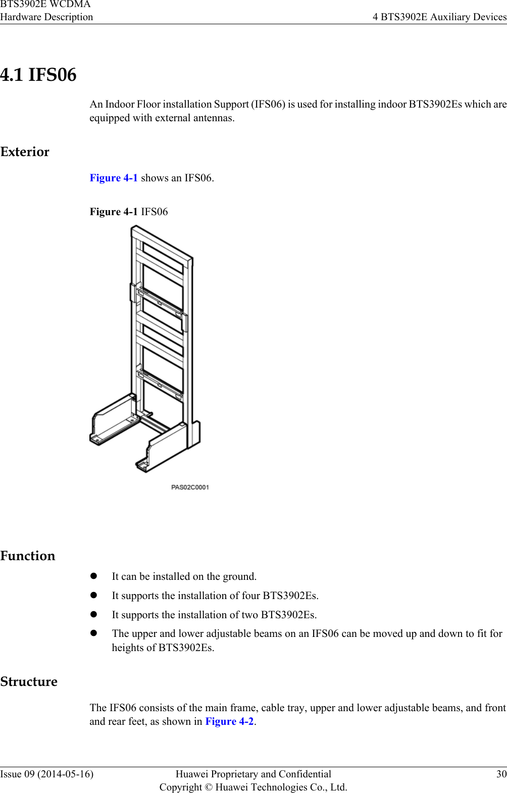

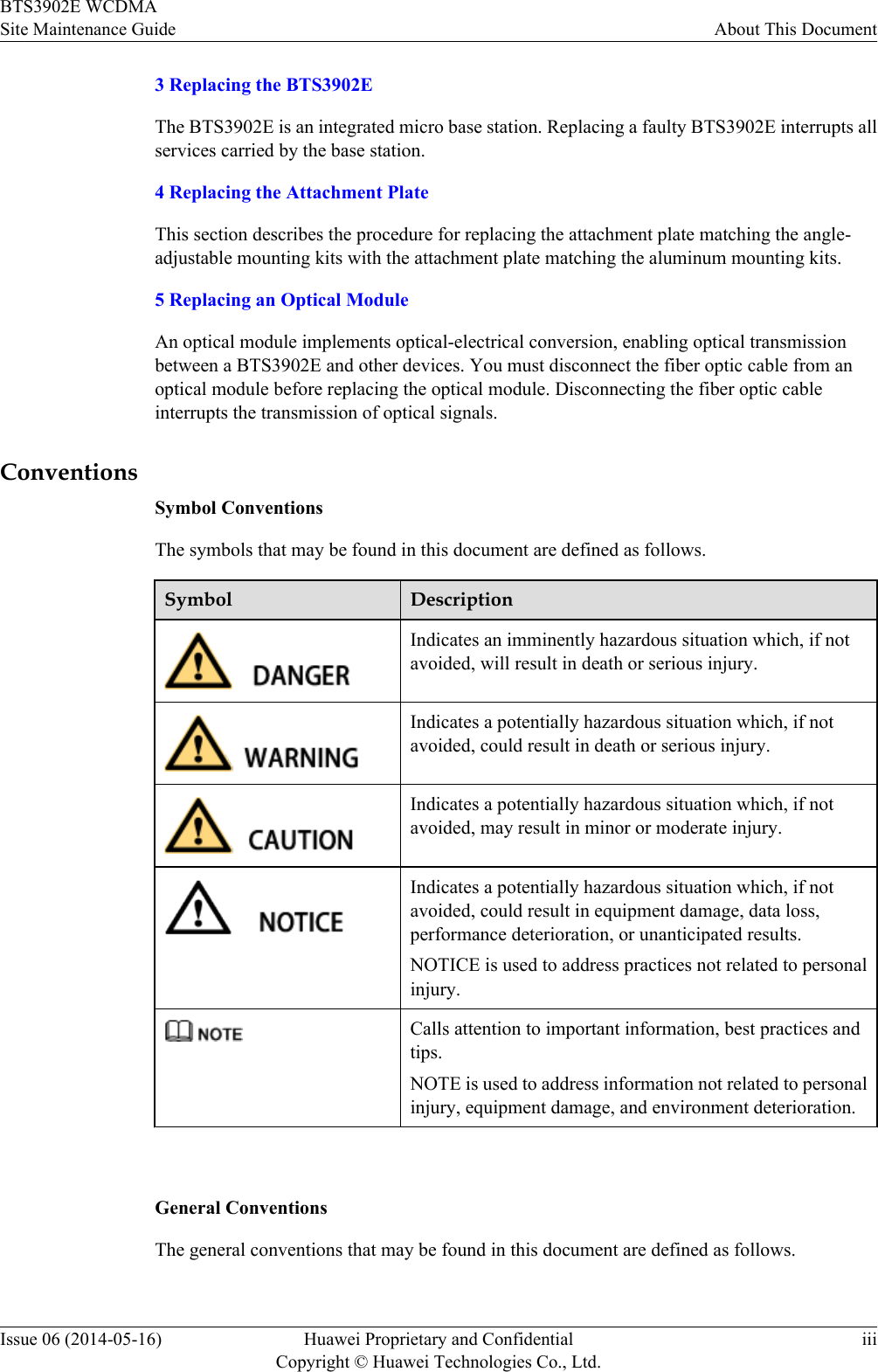
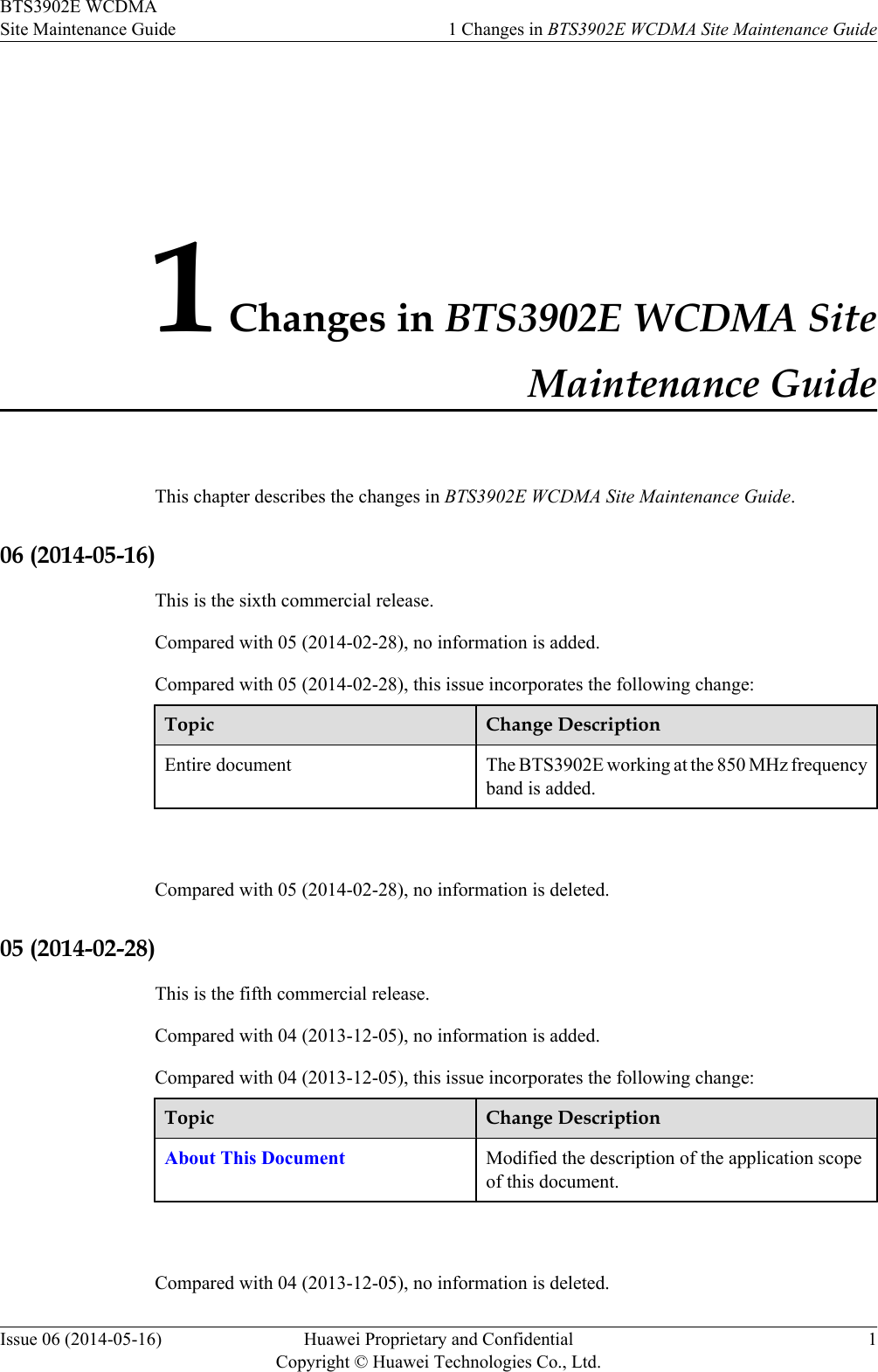
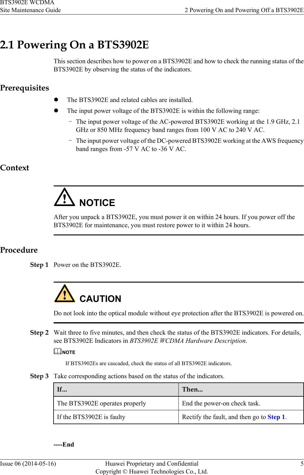
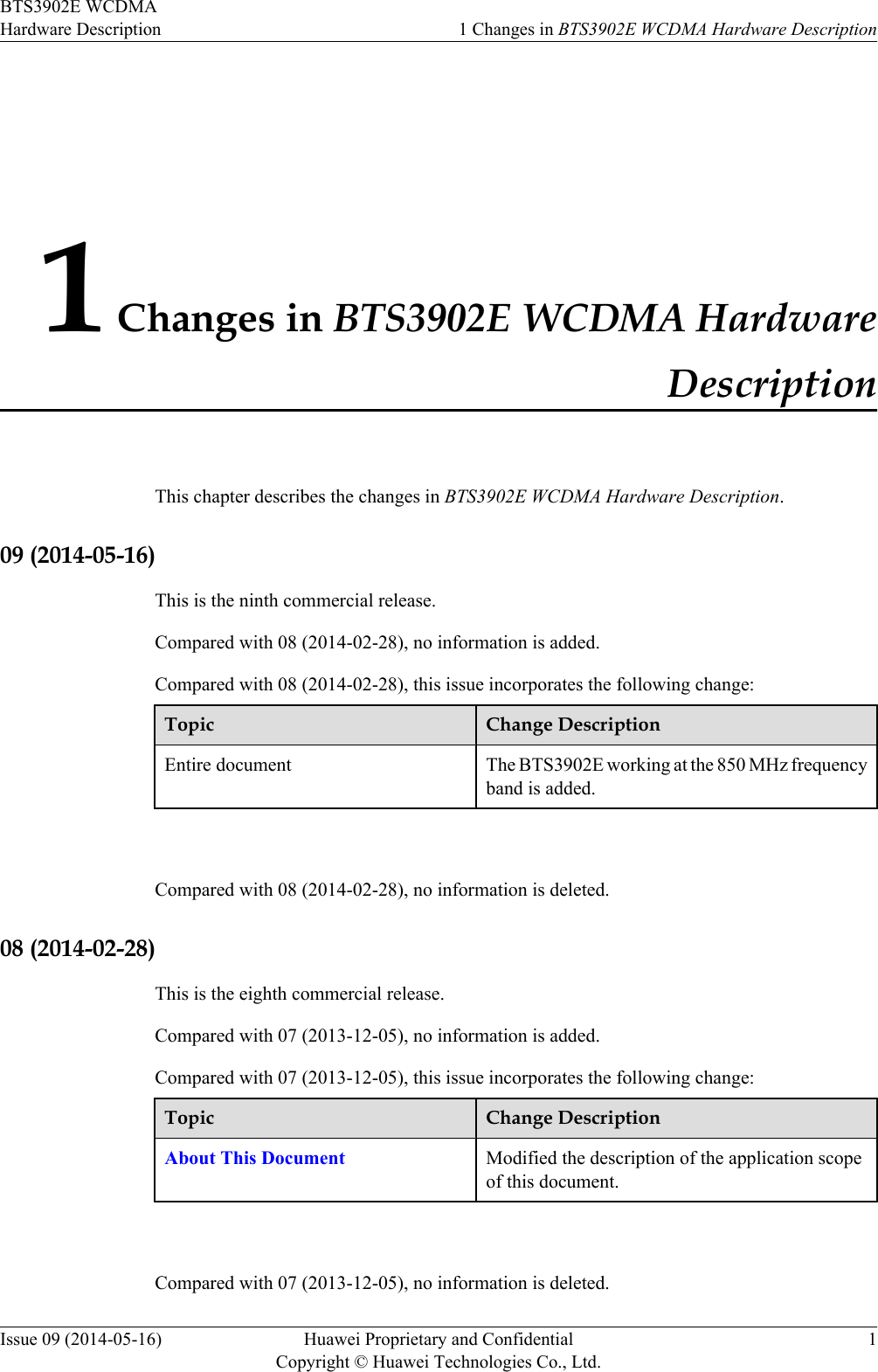
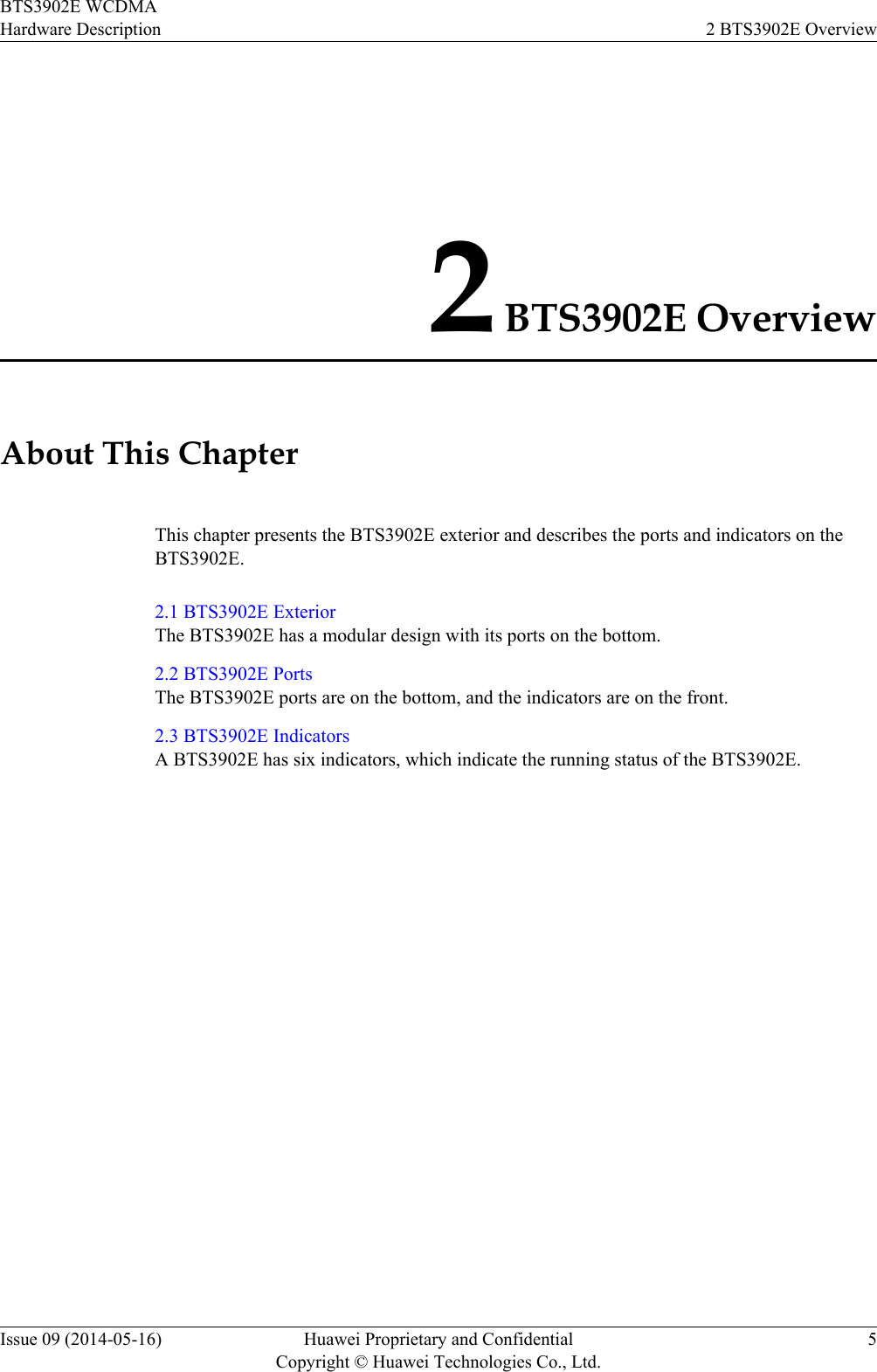
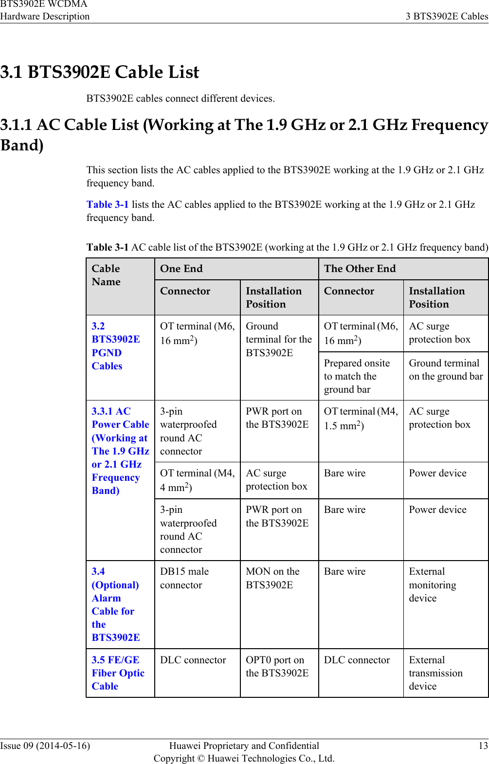
![Convention DescriptionTimes New Roman Normal paragraphs are in Times New Roman.Boldface Names of files, directories, folders, and users are inboldface. For example, log in as user root.Italic Book titles are in italics.Courier New Examples of information displayed on the screen are inCourier New. Command ConventionsThe command conventions that may be found in this document are defined as follows.Convention DescriptionBoldface The keywords of a command line are in boldface.Italic Command arguments are in italics.[ ] Items (keywords or arguments) in brackets [ ] are optional.{ x | y | ... } Optional items are grouped in braces and separated byvertical bars. One item is selected.[ x | y | ... ] Optional items are grouped in brackets and separated byvertical bars. One item is selected or no item is selected.{ x | y | ... }*Optional items are grouped in braces and separated byvertical bars. A minimum of one item or a maximum of allitems can be selected.[ x | y | ... ]*Optional items are grouped in brackets and separated byvertical bars. Several items or no item can be selected. GUI ConventionsThe GUI conventions that may be found in this document are defined as follows.Convention DescriptionBoldface Buttons, menus, parameters, tabs, window, and dialog titlesare in boldface. For example, click OK.>Multi-level menus are in boldface and separated by the ">"signs. For example, choose File > Create > Folder. Keyboard OperationsBTS3902E WCDMASite Maintenance Guide About This DocumentIssue 06 (2014-05-16) Huawei Proprietary and ConfidentialCopyright © Huawei Technologies Co., Ltd.iv](https://usermanual.wiki/Huawei-Technologies/BTS3902E-U850.UserManual-part1-pdf/User-Guide-2303954-Page-47.png)