Huawei Technologies BTS3902E-U850 Micro BTS User Manual Installation Guide
Huawei Technologies Co.,Ltd Micro BTS Installation Guide
UserManual.wiki
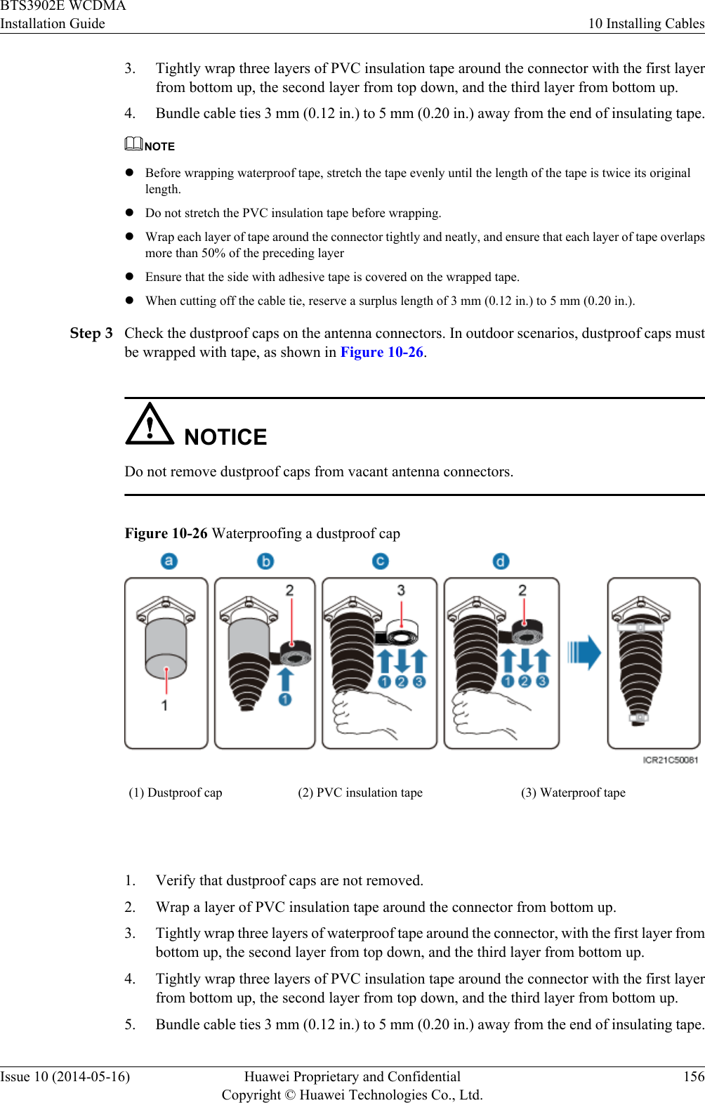
>
Huawei Technologies
>
BTS3902E-U850 User Manual
>
UserManual_part2.pdf
Contents
1.
UserManual_part1.pdf
2.
UserManual_part2.pdf
3.
UserManual_Safety Manual.pdf
UserManual_part2.pdf
Navigation menu
Upload a User Manual
Namespaces
Wiki Guide
HTML
PDF
Info
Views
User Manual
Discussion / Help
Navigation

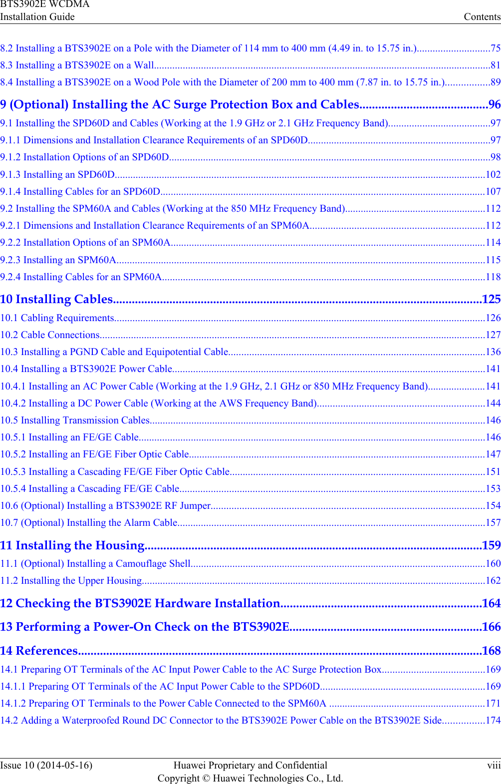
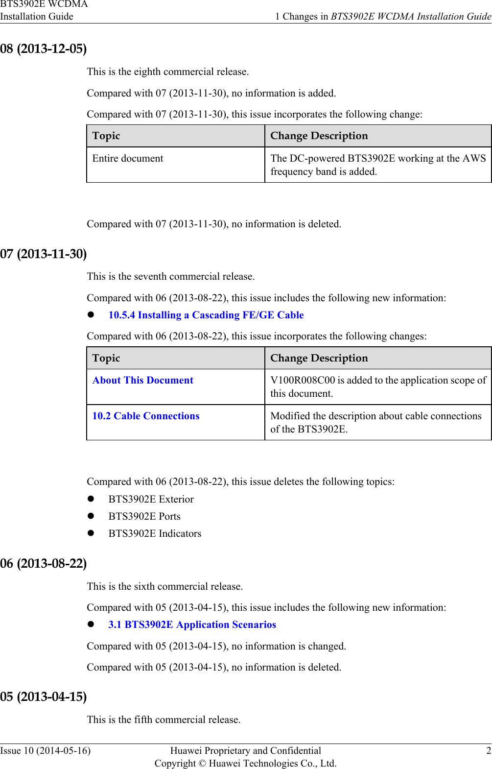
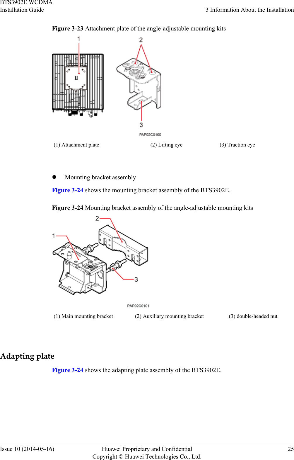
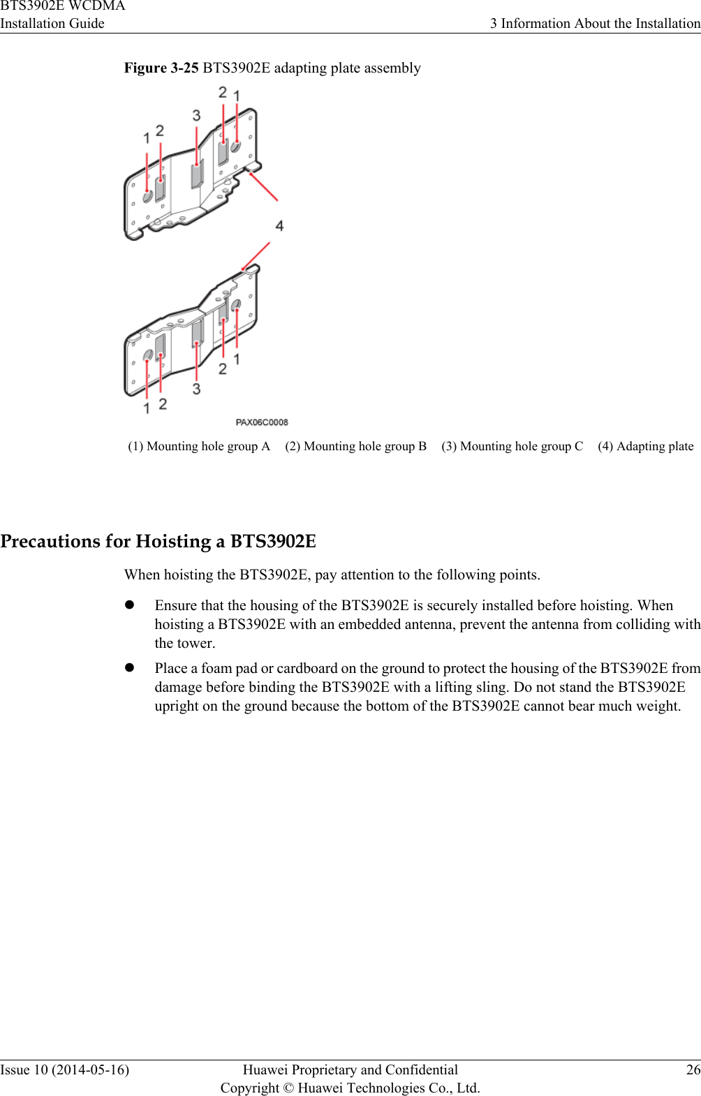
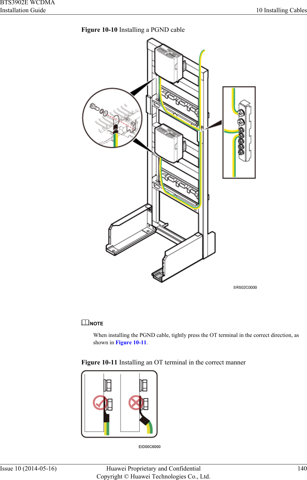
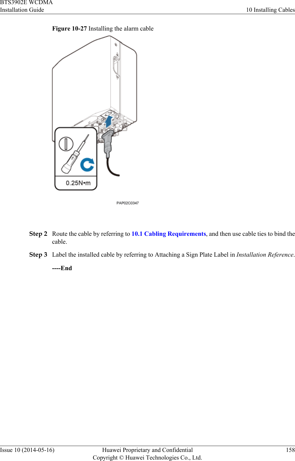
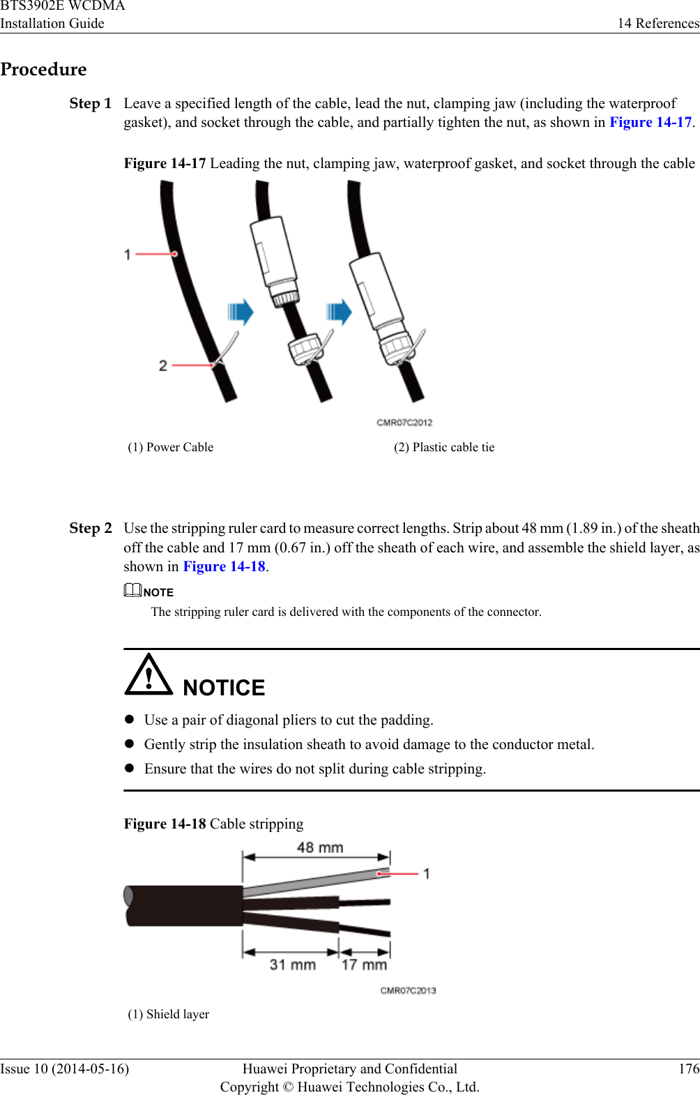
![Command ConventionsThe command conventions that may be found in this document are defined as follows.Convention DescriptionBoldface The keywords of a command line are in boldface.Italic Command arguments are in italics.[ ] Items (keywords or arguments) in brackets [ ] are optional.{ x | y | ... } Optional items are grouped in braces and separated byvertical bars. One item is selected.[ x | y | ... ] Optional items are grouped in brackets and separated byvertical bars. One item is selected or no item is selected.{ x | y | ... }*Optional items are grouped in braces and separated byvertical bars. A minimum of one item or a maximum of allitems can be selected.[ x | y | ... ]*Optional items are grouped in brackets and separated byvertical bars. Several items or no item can be selected. GUI ConventionsThe GUI conventions that may be found in this document are defined as follows.Convention DescriptionBoldface Buttons, menus, parameters, tabs, window, and dialog titlesare in boldface. For example, click OK.>Multi-level menus are in boldface and separated by the ">"signs. For example, choose File > Create > Folder. Keyboard OperationsThe keyboard operations that may be found in this document are defined as follows.Format DescriptionKey Press the key. For example, press Enter and press Tab.Key 1+Key 2 Press the keys concurrently. For example, pressing Ctrl+Alt+A means the three keys should be pressed concurrently.Key 1, Key 2 Press the keys in turn. For example, pressing Alt, A meansthe two keys should be pressed in turn. BTS3902E WCDMAInstallation Guide About This DocumentIssue 10 (2014-05-16) Huawei Proprietary and ConfidentialCopyright © Huawei Technologies Co., Ltd.v](https://usermanual.wiki/Huawei-Technologies/BTS3902E-U850.UserManual-part2-pdf/User-Guide-2303955-Page-6.png)
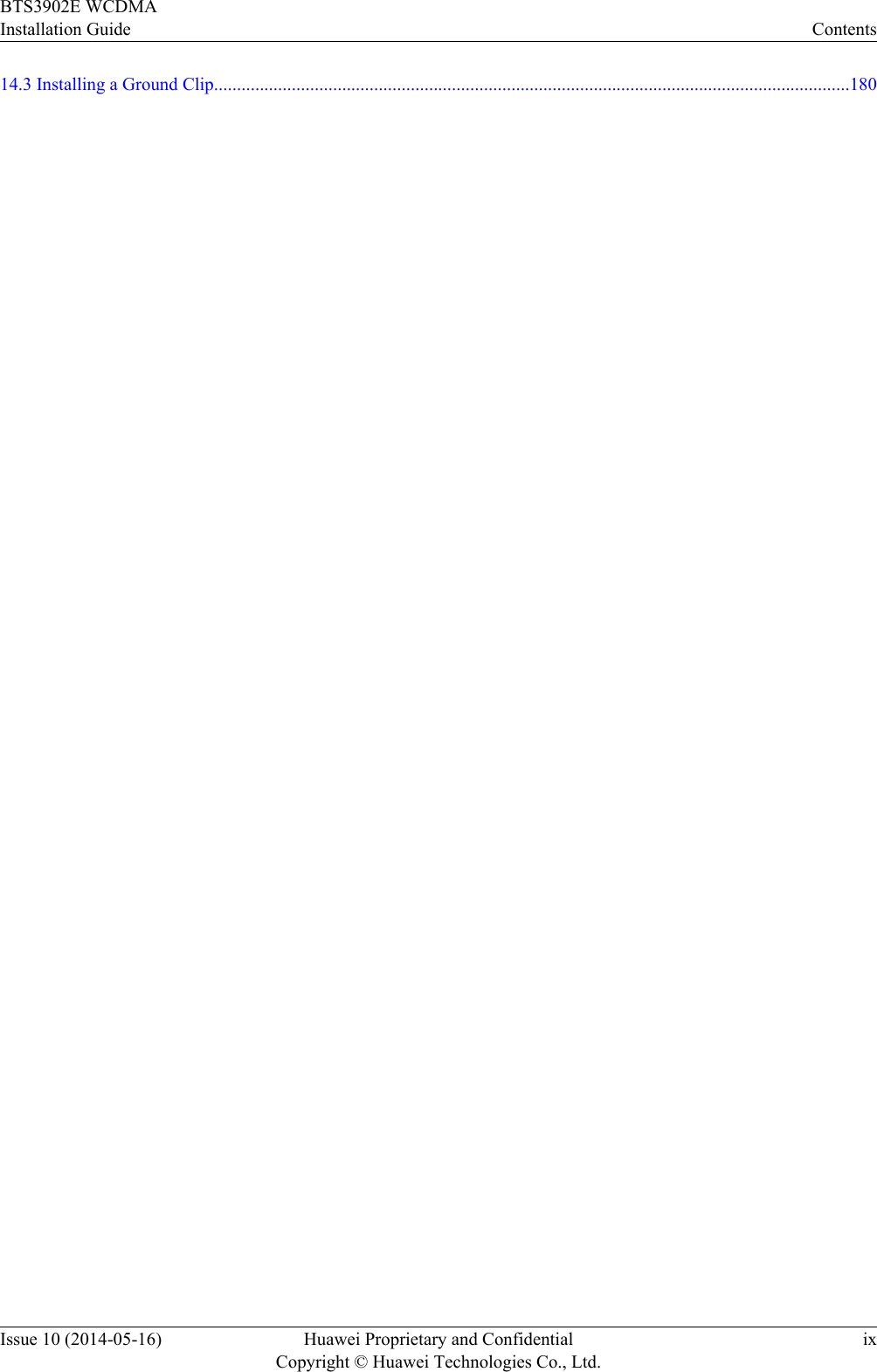
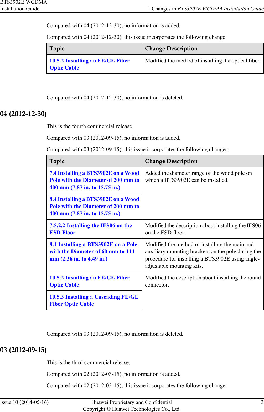


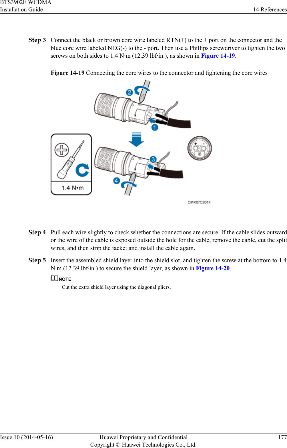
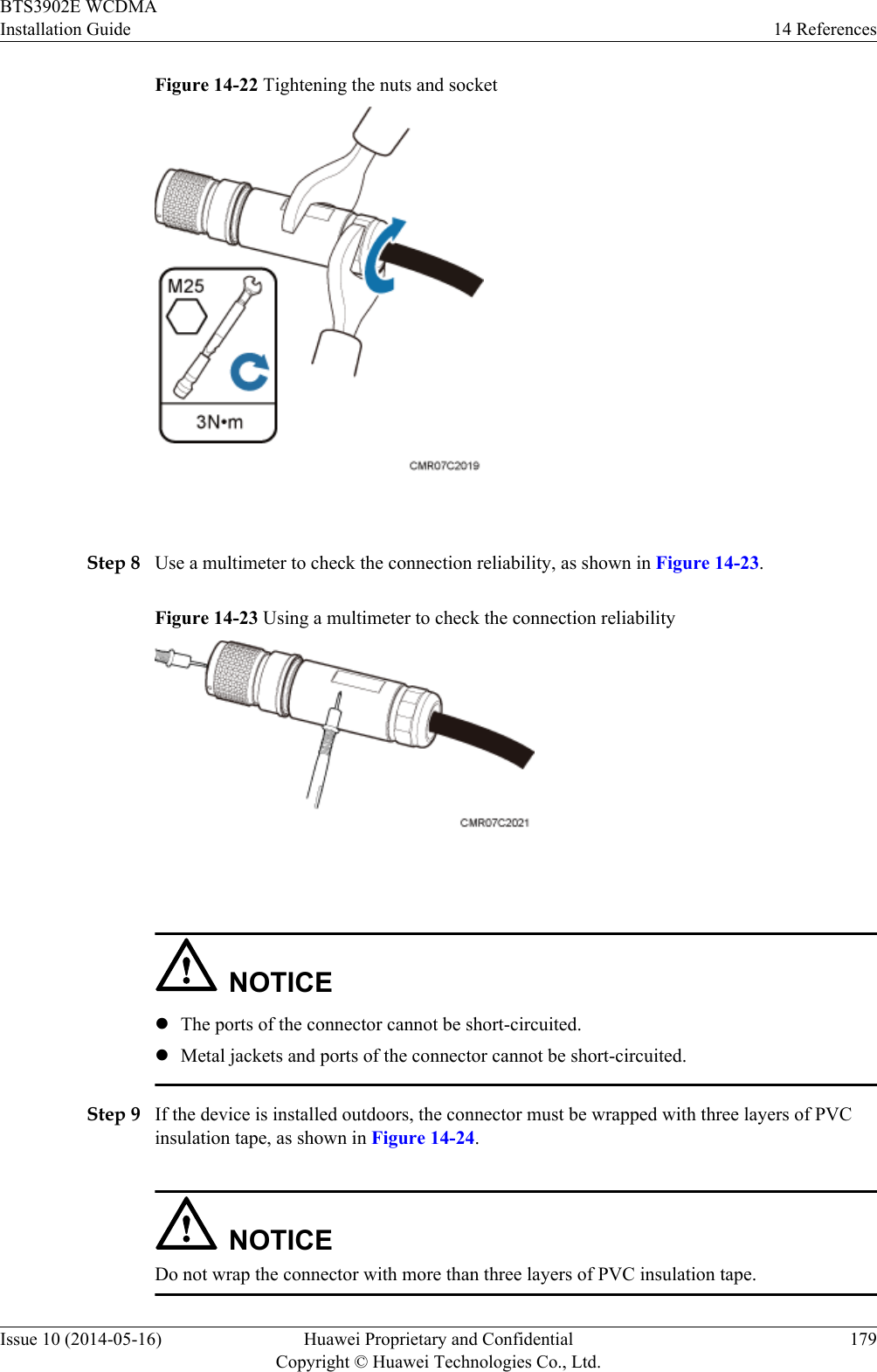
![Figure 14-20 Installing and securing the shield layer(1) Shield layer Step 6 Use your hand to screw the gasket and the protective cover until the red line on the gasket cannotbe seen, as shown in Figure 14-21.Figure 14-21 Tightening the gasket and the protective cover Step 7 Partially tighten the nuts and socket, and then use a combination wrench (capacity: 28 mm [1.1in.]) to secure the nuts, as shown in Figure 14-22.BTS3902E WCDMAInstallation Guide 14 ReferencesIssue 10 (2014-05-16) Huawei Proprietary and ConfidentialCopyright © Huawei Technologies Co., Ltd.178](https://usermanual.wiki/Huawei-Technologies/BTS3902E-U850.UserManual-part2-pdf/User-Guide-2303955-Page-188.png)