Huawei Technologies BTS3902E-U850 Micro BTS User Manual Installation Guide
Huawei Technologies Co.,Ltd Micro BTS Installation Guide
Contents
- 1. UserManual_part1.pdf
- 2. UserManual_part2.pdf
- 3. UserManual_Safety Manual.pdf
UserManual_part2.pdf
BTS3902E WCDMA
Installation Guide
Issue 10
Date 2014-05-16
HUAWEI TECHNOLOGIES CO., LTD.

Copyright © Huawei Technologies Co., Ltd. 2014. All rights reserved.
No part of this document may be reproduced or transmitted in any form or by any means without prior written
consent of Huawei Technologies Co., Ltd.
Trademarks and Permissions
and other Huawei trademarks are trademarks of Huawei Technologies Co., Ltd.
All other trademarks and trade names mentioned in this document are the property of their respective holders.
Notice
The purchased products, services and features are stipulated by the contract made between Huawei and the
customer. All or part of the products, services and features described in this document may not be within the
purchase scope or the usage scope. Unless otherwise specified in the contract, all statements, information,
and recommendations in this document are provided "AS IS" without warranties, guarantees or representations
of any kind, either express or implied.
The information in this document is subject to change without notice. Every effort has been made in the
preparation of this document to ensure accuracy of the contents, but all statements, information, and
recommendations in this document do not constitute a warranty of any kind, express or implied.
Huawei Technologies Co., Ltd.
Address: Huawei Industrial Base
Bantian, Longgang
Shenzhen 518129
People's Republic of China
Website: http://www.huawei.com
Email: support@huawei.com
Issue 10 (2014-05-16) Huawei Proprietary and Confidential
Copyright © Huawei Technologies Co., Ltd.
i
About This Document
Purpose
This document describes the procedures for installing a BTS3902E WCDMA in different
scenarios. It also provides checklists for hardware installation.
Product Version
The following table lists the product version related to this document.
Product Name Product Version
BTS3902E WCDMA (referred to
as the BTS3902E in this
document)
V200R013C00 and later versions
V100R008C00 and later versions
The single-mode base station version mapping to
V100R008C00 is: NodeB V200R015C00
Intended Audience
This document is intended for:
lBase station installation engineers
lSystem engineers
lSite maintenance engineers
Organization
1 Changes in BTS3902E WCDMA Installation Guide
This chapter describes the changes in BTS3902E WCDMA Installation Guide.
2 Installation Preparations
This chapter describes instrument preparations, and skills and qualifications that installation
engineers must possess.
BTS3902E WCDMA
Installation Guide About This Document
Issue 10 (2014-05-16) Huawei Proprietary and Confidential
Copyright © Huawei Technologies Co., Ltd.
ii

3 Information About the Installation
This chapter describes the information that you must be familiar with before installing a
BTS3902E, including the BTS3902E application scenarios, installation options, physical
supports, and installation clearance requirements.
4 Unpacking the Equipment
Unpack and check the delivered equipment to ensure that all the materials are included and intact.
5 Obtaining the ESN
The Electronic Serial Number (ESN) is a unique identifier of a device. It is used during base
station commissioning. Therefore, record the ESN before installing the BTS3902E.There are
two types of the BTS3902E. This document uses one type as the example to describe.
6 Installation Process
This chapter describes the procedures for installing the BTS3902E. The procedures involve
installing a BTS3902E, installing BTS3902E cables, checking the BTS3902E hardware
installation, and powering on the BTS3902E.
7 Installing a BTS3902E (using aluminum mounting kits)
This chapter describes the procedure for installing a BTS3902E with an external antenna, when
an aluminum mounting kit is used. The BTS3902E can be installed on a metal pole, wall, wood
pole, or IFS06 in different scenarios.
8 Installing a BTS3902E (using angle-adjustable mounting kits)
This chapter describes the procedure for installing a BTS3902E with an embedded antenna,
when an angle-adjustable mounting kit is used. The BTS3902E can be installed on a metal pole,
wall, wood pole in different scenarios.
9 (Optional) Installing the AC Surge Protection Box and Cables
This chapter describes the dimensions, installation clearance requirements, and installation
options of an AC surge protection box as well as the procedure for installing the surge protection
box. The AC surge protection box can be configured when the BTS3902E is installed outdoors.
Two types of surge protection boxes SPD60D and SPM60A are available for the BTS3902E.
10 Installing Cables
This chapter describes the procedures and precautions for installing the PGND cables, power
cables, and transmission cables for BTS3902Es installed in various scenarios. It also describes
the procedures and precautions for installing an optional alarm cable.
11 Installing the Housing
This chapter describes the procedures for installing the upper housing and optional camouflage
shell for a BTS3902E after the BTS3902E and related cables are installed. There are two types
of the BTS3902E. This document uses one type as the example to describe how to install the
housing.
12 Checking the BTS3902E Hardware Installation
This chapter describes how to check the hardware installation after a BTS3902E is installed.
13 Performing a Power-On Check on the BTS3902E
BTS3902E WCDMA
Installation Guide About This Document
Issue 10 (2014-05-16) Huawei Proprietary and Confidential
Copyright © Huawei Technologies Co., Ltd.
iii
This chapter describes the procedure for performing a power-on check on the BTS3902E.
14 References
This chapter describes reference information during installation.
Conventions
Symbol Conventions
The symbols that may be found in this document are defined as follows.
Symbol Description
Indicates an imminently hazardous situation which, if not
avoided, will result in death or serious injury.
Indicates a potentially hazardous situation which, if not
avoided, could result in death or serious injury.
Indicates a potentially hazardous situation which, if not
avoided, may result in minor or moderate injury.
Indicates a potentially hazardous situation which, if not
avoided, could result in equipment damage, data loss,
performance deterioration, or unanticipated results.
NOTICE is used to address practices not related to personal
injury.
Calls attention to important information, best practices and
tips.
NOTE is used to address information not related to personal
injury, equipment damage, and environment deterioration.
General Conventions
The general conventions that may be found in this document are defined as follows.
Convention Description
Times New Roman Normal paragraphs are in Times New Roman.
Boldface Names of files, directories, folders, and users are in
boldface. For example, log in as user root.
Italic Book titles are in italics.
Courier New Examples of information displayed on the screen are in
Courier New.
BTS3902E WCDMA
Installation Guide About This Document
Issue 10 (2014-05-16) Huawei Proprietary and Confidential
Copyright © Huawei Technologies Co., Ltd.
iv
Command Conventions
The command conventions that may be found in this document are defined as follows.
Convention Description
Boldface The keywords of a command line are in boldface.
Italic Command arguments are in italics.
[ ] Items (keywords or arguments) in brackets [ ] are optional.
{ x | y | ... } Optional items are grouped in braces and separated by
vertical bars. One item is selected.
[ x | y | ... ] Optional items are grouped in brackets and separated by
vertical bars. One item is selected or no item is selected.
{ x | y | ... }*Optional items are grouped in braces and separated by
vertical bars. A minimum of one item or a maximum of all
items can be selected.
[ x | y | ... ]*Optional items are grouped in brackets and separated by
vertical bars. Several items or no item can be selected.
GUI Conventions
The GUI conventions that may be found in this document are defined as follows.
Convention Description
Boldface Buttons, menus, parameters, tabs, window, and dialog titles
are in boldface. For example, click OK.
>Multi-level menus are in boldface and separated by the ">"
signs. For example, choose File > Create > Folder.
Keyboard Operations
The keyboard operations that may be found in this document are defined as follows.
Format Description
Key Press the key. For example, press Enter and press Tab.
Key 1+Key 2 Press the keys concurrently. For example, pressing Ctrl+Alt
+A means the three keys should be pressed concurrently.
Key 1, Key 2 Press the keys in turn. For example, pressing Alt, A means
the two keys should be pressed in turn.
BTS3902E WCDMA
Installation Guide About This Document
Issue 10 (2014-05-16) Huawei Proprietary and Confidential
Copyright © Huawei Technologies Co., Ltd.
v

Mouse Operations
The mouse operations that may be found in this document are defined as follows.
Action Description
Click Select and release the primary mouse button without moving
the pointer.
Double-click Press the primary mouse button twice continuously and
quickly without moving the pointer.
Drag Press and hold the primary mouse button and move the
pointer to a certain position.
BTS3902E WCDMA
Installation Guide About This Document
Issue 10 (2014-05-16) Huawei Proprietary and Confidential
Copyright © Huawei Technologies Co., Ltd.
vi

Contents
About This Document.....................................................................................................................ii
1 Changes in BTS3902E WCDMA Installation Guide................................................................1
2 Installation Preparations..............................................................................................................6
2.1 Document Preparations...................................................................................................................................................7
2.2 Tools and Instruments....................................................................................................................................................7
2.3 Skills and Requirements for Onsite Personnel...............................................................................................................8
3 Information About the Installation...........................................................................................9
3.1 BTS3902E Application Scenarios................................................................................................................................10
3.2 BTS3902E Installation Options....................................................................................................................................10
3.3 Installation Clearance Requirements............................................................................................................................17
3.4 Mounting Kits for Installing a BTS3902E...................................................................................................................23
4 Unpacking the Equipment.........................................................................................................27
5 Obtaining the ESN......................................................................................................................29
6 Installation Process.....................................................................................................................32
7 Installing a BTS3902E (using aluminum mounting kits)....................................................34
7.1 Installing a BTS3902E on a Pole with the Diameter of 60 mm to 114 mm (2.36 in. to 4.49 in.)................................35
7.2 Installing a BTS3902E on a Pole with the Diameter of 114 mm to 400 mm (4.49 in. to 15.75 in.)............................36
7.3 Installing a BTS3902E on a Wall.................................................................................................................................40
7.4 Installing a BTS3902E on a Wood Pole with the Diameter of 200 mm to 400 mm (7.87 in. to 15.75 in.).................44
7.5 Installing BTS3902Es on an IFS06..............................................................................................................................49
7.5.1 Assembling the IFS06...............................................................................................................................................49
7.5.2 Installing the IFS06...................................................................................................................................................52
7.5.2.1 Installing the IFS06 on the Concrete Floor............................................................................................................52
7.5.2.2 Installing the IFS06 on the ESD Floor...................................................................................................................55
7.5.3 Installing a Main Bracket..........................................................................................................................................62
7.5.4 Installing an IFS06 PGND Cable..............................................................................................................................66
7.5.5 Installing BTS3902Es................................................................................................................................................68
8 Installing a BTS3902E (using angle-adjustable mounting kits).........................................70
8.1 Installing a BTS3902E on a Pole with the Diameter of 60 mm to 114 mm (2.36 in. to 4.49 in.)................................71
BTS3902E WCDMA
Installation Guide Contents
Issue 10 (2014-05-16) Huawei Proprietary and Confidential
Copyright © Huawei Technologies Co., Ltd.
vii

8.2 Installing a BTS3902E on a Pole with the Diameter of 114 mm to 400 mm (4.49 in. to 15.75 in.)............................75
8.3 Installing a BTS3902E on a Wall.................................................................................................................................81
8.4 Installing a BTS3902E on a Wood Pole with the Diameter of 200 mm to 400 mm (7.87 in. to 15.75 in.).................89
9 (Optional) Installing the AC Surge Protection Box and Cables.........................................96
9.1 Installing the SPD60D and Cables (Working at the 1.9 GHz or 2.1 GHz Frequency Band).......................................97
9.1.1 Dimensions and Installation Clearance Requirements of an SPD60D......................................................................97
9.1.2 Installation Options of an SPD60D...........................................................................................................................98
9.1.3 Installing an SPD60D..............................................................................................................................................102
9.1.4 Installing Cables for an SPD60D.............................................................................................................................107
9.2 Installing the SPM60A and Cables (Working at the 850 MHz Frequency Band)......................................................112
9.2.1 Dimensions and Installation Clearance Requirements of an SPM60A...................................................................112
9.2.2 Installation Options of an SPM60A.........................................................................................................................114
9.2.3 Installing an SPM60A.............................................................................................................................................115
9.2.4 Installing Cables for an SPM60A............................................................................................................................118
10 Installing Cables......................................................................................................................125
10.1 Cabling Requirements..............................................................................................................................................126
10.2 Cable Connections....................................................................................................................................................127
10.3 Installing a PGND Cable and Equipotential Cable..................................................................................................136
10.4 Installing a BTS3902E Power Cable........................................................................................................................141
10.4.1 Installing an AC Power Cable (Working at the 1.9 GHz, 2.1 GHz or 850 MHz Frequency Band)......................141
10.4.2 Installing a DC Power Cable (Working at the AWS Frequency Band)................................................................144
10.5 Installing Transmission Cables.................................................................................................................................146
10.5.1 Installing an FE/GE Cable.....................................................................................................................................146
10.5.2 Installing an FE/GE Fiber Optic Cable..................................................................................................................147
10.5.3 Installing a Cascading FE/GE Fiber Optic Cable..................................................................................................151
10.5.4 Installing a Cascading FE/GE Cable.....................................................................................................................153
10.6 (Optional) Installing a BTS3902E RF Jumper.........................................................................................................154
10.7 (Optional) Installing the Alarm Cable......................................................................................................................157
11 Installing the Housing............................................................................................................159
11.1 (Optional) Installing a Camouflage Shell.................................................................................................................160
11.2 Installing the Upper Housing....................................................................................................................................162
12 Checking the BTS3902E Hardware Installation................................................................164
13 Performing a Power-On Check on the BTS3902E.............................................................166
14 References.................................................................................................................................168
14.1 Preparing OT Terminals of the AC Input Power Cable to the AC Surge Protection Box.......................................169
14.1.1 Preparing OT Terminals of the AC Input Power Cable to the SPD60D...............................................................169
14.1.2 Preparing OT Terminals to the Power Cable Connected to the SPM60A ............................................................171
14.2 Adding a Waterproofed Round DC Connector to the BTS3902E Power Cable on the BTS3902E Side................174
BTS3902E WCDMA
Installation Guide Contents
Issue 10 (2014-05-16) Huawei Proprietary and Confidential
Copyright © Huawei Technologies Co., Ltd.
viii

14.3 Installing a Ground Clip...........................................................................................................................................180
BTS3902E WCDMA
Installation Guide Contents
Issue 10 (2014-05-16) Huawei Proprietary and Confidential
Copyright © Huawei Technologies Co., Ltd.
ix
1 Changes in BTS3902E WCDMA Installation
Guide
This chapter describes the changes in BTS3902E WCDMA Installation Guide.
10 (2014-05-16)
This is the tenth commercial release.
Compared with 09 (2014-02-28), no information is added.
Compared with 09 (2014-02-28), this issue incorporates the following change:
Topic Change Description
Entire document The BTS3902E working at the 850 MHz frequency
band is added.
Compared with 09 (2014-02-28), no information is deleted.
09 (2014-02-28)
This is the ninth commercial release.
Compared with 08 (2013-12-05), no information is added.
Compared with 08 (2013-12-05), this issue incorporates the following change:
Topic Change Description
About This Document Modified the description of the application scope
of this document.
Compared with 08 (2013-12-05), no information is deleted.
BTS3902E WCDMA
Installation Guide 1 Changes in BTS3902E WCDMA Installation Guide
Issue 10 (2014-05-16) Huawei Proprietary and Confidential
Copyright © Huawei Technologies Co., Ltd.
1
08 (2013-12-05)
This is the eighth commercial release.
Compared with 07 (2013-11-30), no information is added.
Compared with 07 (2013-11-30), this issue incorporates the following change:
Topic Change Description
Entire document The DC-powered BTS3902E working at the AWS
frequency band is added.
Compared with 07 (2013-11-30), no information is deleted.
07 (2013-11-30)
This is the seventh commercial release.
Compared with 06 (2013-08-22), this issue includes the following new information:
l10.5.4 Installing a Cascading FE/GE Cable
Compared with 06 (2013-08-22), this issue incorporates the following changes:
Topic Change Description
About This Document V100R008C00 is added to the application scope of
this document.
10.2 Cable Connections Modified the description about cable connections
of the BTS3902E.
Compared with 06 (2013-08-22), this issue deletes the following topics:
lBTS3902E Exterior
lBTS3902E Ports
lBTS3902E Indicators
06 (2013-08-22)
This is the sixth commercial release.
Compared with 05 (2013-04-15), this issue includes the following new information:
l3.1 BTS3902E Application Scenarios
Compared with 05 (2013-04-15), no information is changed.
Compared with 05 (2013-04-15), no information is deleted.
05 (2013-04-15)
This is the fifth commercial release.
BTS3902E WCDMA
Installation Guide 1 Changes in BTS3902E WCDMA Installation Guide
Issue 10 (2014-05-16) Huawei Proprietary and Confidential
Copyright © Huawei Technologies Co., Ltd.
2
Compared with 04 (2012-12-30), no information is added.
Compared with 04 (2012-12-30), this issue incorporates the following change:
Topic Change Description
10.5.2 Installing an FE/GE Fiber
Optic Cable
Modified the method of installing the optical fiber.
Compared with 04 (2012-12-30), no information is deleted.
04 (2012-12-30)
This is the fourth commercial release.
Compared with 03 (2012-09-15), no information is added.
Compared with 03 (2012-09-15), this issue incorporates the following changes:
Topic Change Description
7.4 Installing a BTS3902E on a Wood
Pole with the Diameter of 200 mm to
400 mm (7.87 in. to 15.75 in.)
Added the diameter range of the wood pole on
which a BTS3902E can be installed.
8.4 Installing a BTS3902E on a Wood
Pole with the Diameter of 200 mm to
400 mm (7.87 in. to 15.75 in.)
7.5.2.2 Installing the IFS06 on the
ESD Floor
Modified the description about installing the IFS06
on the ESD floor.
8.1 Installing a BTS3902E on a Pole
with the Diameter of 60 mm to 114
mm (2.36 in. to 4.49 in.)
Modified the method of installing the main and
auxiliary mounting brackets on the pole during the
procedure for installing a BTS3902E using angle-
adjustable mounting kits.
10.5.2 Installing an FE/GE Fiber
Optic Cable
Modified the description about installing the round
connector.
10.5.3 Installing a Cascading FE/GE
Fiber Optic Cable
Compared with 03 (2012-09-15), no information is deleted.
03 (2012-09-15)
This is the third commercial release.
Compared with 02 (2012-03-15), no information is added.
Compared with 02 (2012-03-15), this issue incorporates the following change:
BTS3902E WCDMA
Installation Guide 1 Changes in BTS3902E WCDMA Installation Guide
Issue 10 (2014-05-16) Huawei Proprietary and Confidential
Copyright © Huawei Technologies Co., Ltd.
3
Topic Change Description
10.2 Cable Connections Modified the description about cable connections.
Compared with 02 (2012-03-15), no information is deleted.
02 (2012-03-15)
This is the second commercial release.
Compared with 01 (2011-11-19), this issue includes the following new information:
l3.4 Mounting Kits for Installing a BTS3902E
l8 Installing a BTS3902E (using angle-adjustable mounting kits)
Compared with 01 (2011-11-19), this issue incorporates the following changes:
Topic Change Description
Entire document Modified the flanges on the optical and electrical
ports on the BTS3902E to hexagons.
10.2 Cable Connections Deleted the description about cable connections of
power over Ethernet (PoE).
Compared with 01 (2011-11-19), no information is deleted.
01 (2011-11-19)
This is the first commercial release.
Compared with draft B (2011-09-22), no information is added.
Compared with draft B (2011-09-22), no information is changed.
Compared with draft B (2011-09-22), no information is deleted.
Draft B (2011-09-22)
This is a draft release.
Compared with draft A (2011-06-30), this issue includes the following new information:
l7.5 Installing BTS3902Es on an IFS06
Compared with draft A (2011-06-30), this issue incorporates the following changes:
Topic Change Description
5 Obtaining the ESN The position of the ESN is modified.
BTS3902E WCDMA
Installation Guide 1 Changes in BTS3902E WCDMA Installation Guide
Issue 10 (2014-05-16) Huawei Proprietary and Confidential
Copyright © Huawei Technologies Co., Ltd.
4

Topic Change Description
10.5.2 Installing an FE/GE Fiber
Optic Cable
Added the caution for installing an optical module.
10.5.3 Installing a Cascading FE/GE
Fiber Optic Cable
Compared with draft A (2011-06-30), no information is deleted.
Draft A (2011-06-30)
This is a draft release.
BTS3902E WCDMA
Installation Guide 1 Changes in BTS3902E WCDMA Installation Guide
Issue 10 (2014-05-16) Huawei Proprietary and Confidential
Copyright © Huawei Technologies Co., Ltd.
5

2 Installation Preparations
About This Chapter
This chapter describes instrument preparations, and skills and qualifications that installation
engineers must possess.
2.1 Document Preparations
This section describes the reference documents that must be ready before the installation.
2.2 Tools and Instruments
This section lists the tools and instruments that must be obtained before installation.
2.3 Skills and Requirements for Onsite Personnel
Onsite personnel must be qualified and trained. Before performing any operation, onsite
personnel must be familiar with correct operation methods and safety precautions.
BTS3902E WCDMA
Installation Guide 2 Installation Preparations
Issue 10 (2014-05-16) Huawei Proprietary and Confidential
Copyright © Huawei Technologies Co., Ltd.
6
2.1 Document Preparations
This section describes the reference documents that must be ready before the installation.
lBefore the installation, you must familiar with the following reference documents:
–BTS3902E WCDMA Hardware Description
–Safety Information
lDuring the installation, you must familiar with the following reference document:
–Installation Reference
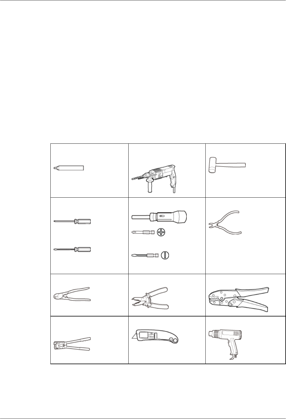
2.2 Tools and Instruments
This section lists the tools and instruments that must be obtained before installation.
Marker (diameter ≤ 10 mm
or 0.39 in.)
Hammer drill (with a φ12 bit,
φ14 bit, φ16 bit, and φ18 bit)
Rubber mallet
Phillips screwdriver (M3 to
M6)
Flat-head screwdriver (M3 to
M6)
Torque screwdriver
(M3 to M8)
(M3 to M8)
Diagonal pliers
Wire clippers Wire stripper COAX crimping tool
Crimping tool for power
cables
Utility knife Heat gun
BTS3902E WCDMA
Installation Guide 2 Installation Preparations
Issue 10 (2014-05-16) Huawei Proprietary and Confidential
Copyright © Huawei Technologies Co., Ltd.
7
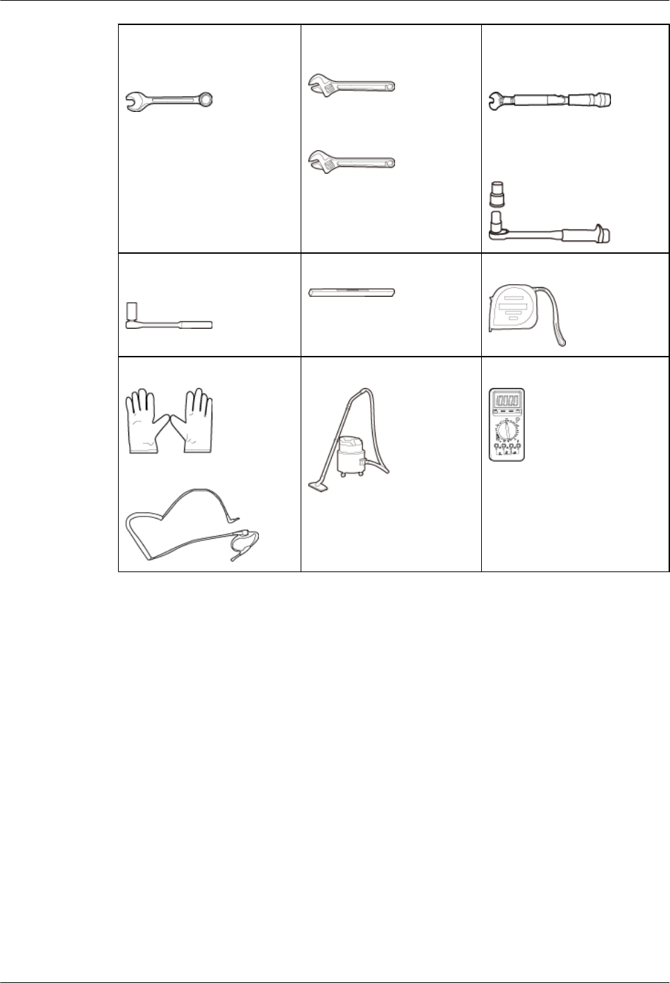
Combination wrench (size:
17 mm or 0.67 in., 19 mm or
0.75 in., 21 mm or 0.83 in.)
Adjustable wrench (size ≥
32 mm or 1.26 in.)
Adjustable wrench (size ≤
19 mm or 0.75 in.)
Torque wrench (size: 17 mm
or 0.67 in., 19 mm or 0.75 in.,
21 mm or 0.83 in.)
Torque wrench (30 N·m to 50
N·m, or 265.52 lbf·in. to
442.54 lbf·in.)
Socket wrench (M10 and
M12)
Level Measuring tape
ESD gloves
ESD wrist strap
Vacuum cleaner Multimeter
2.3 Skills and Requirements for Onsite Personnel
Onsite personnel must be qualified and trained. Before performing any operation, onsite
personnel must be familiar with correct operation methods and safety precautions.
Before the installation, pay attention to the following items:
lThe customer's technical engineers must be trained by Huawei and be familiar with the
proper installation and operation methods.
lThe number of onsite personnel depends on the engineering schedule and installation
environment. Generally, only three to five onsite personnel are necessary.
BTS3902E WCDMA
Installation Guide 2 Installation Preparations
Issue 10 (2014-05-16) Huawei Proprietary and Confidential
Copyright © Huawei Technologies Co., Ltd.
8

3 Information About the Installation
About This Chapter
This chapter describes the information that you must be familiar with before installing a
BTS3902E, including the BTS3902E application scenarios, installation options, physical
supports, and installation clearance requirements.
3.1 BTS3902E Application Scenarios
This section describes the application scenarios of the BTS3902E.
3.2 BTS3902E Installation Options
This section describes the BTS3902E installation options. The BTS3902E can be installed on a
metal pole, wood pole, wall, or IFS06.
3.3 Installation Clearance Requirements
This section describes the clearance requirements for installing a BTS3902E on a metal pole,
wood pole, wall, or IFS06.
3.4 Mounting Kits for Installing a BTS3902E
This section describes the mounting kits for a BTS3902E and the precautions for hoisting the
BTS3902E.
BTS3902E WCDMA
Installation Guide 3 Information About the Installation
Issue 10 (2014-05-16) Huawei Proprietary and Confidential
Copyright © Huawei Technologies Co., Ltd.
9
3.1 BTS3902E Application Scenarios
This section describes the application scenarios of the BTS3902E.
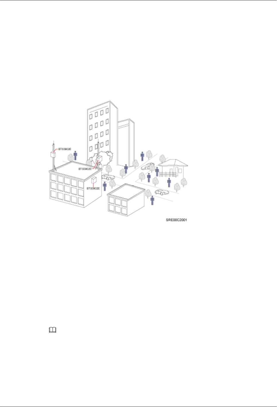
The BTS3902E works well for covering hot spots and reducing blind spots. Insufficient network
capacity in hot spots and blind spots greatly affect user experience. With its flexible deployment,
the low-cost BTS3902E helps operators solve these problems. Figure 3-1application scenarios
for the BTS3902E.
Figure 3-1 BTS3902EApplication Scenarios
3.2 BTS3902E Installation Options
This section describes the BTS3902E installation options. The BTS3902E can be installed on a
metal pole, wood pole, wall, or IFS06.
On a Metal Pole with the Diameter Ranging from 60 mm to 114 mm (2.36 in. to 4.49
in.)
Figure 3-2 shows the diameter of a metal pole for installing a BTS3902E.
NOTE
The recommended diameter is 80 mm (3.15 in.).
BTS3902E WCDMA
Installation Guide 3 Information About the Installation
Issue 10 (2014-05-16) Huawei Proprietary and Confidential
Copyright © Huawei Technologies Co., Ltd.
10
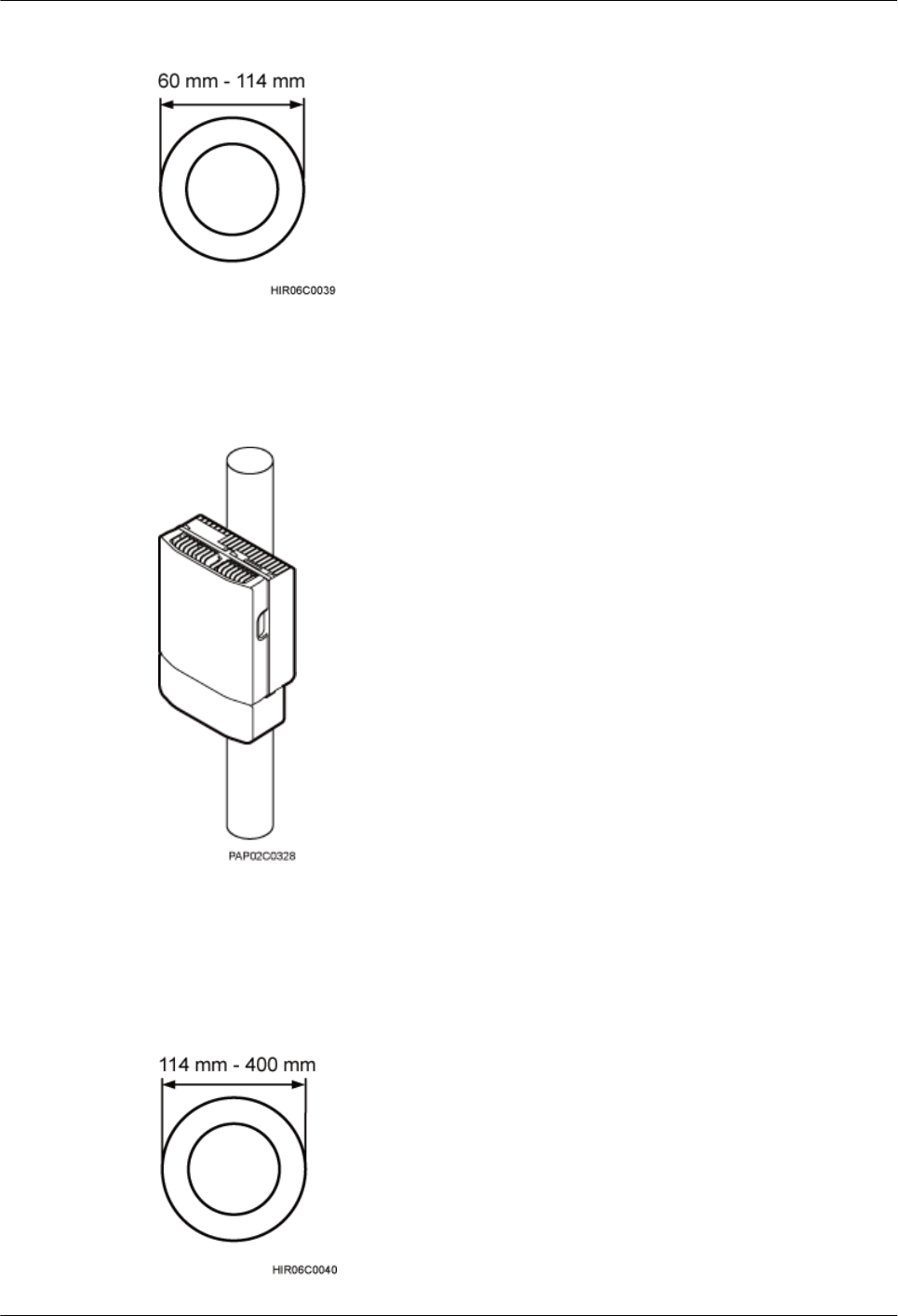
Figure 3-2 Diameter of a pole
Figure 3-3 shows the BTS3902E installed on a metal pole.
Figure 3-3 BTS3902E installed on a metal pole
On a Metal Pole with the Diameter Ranging from 114 mm to 400 mm (4.49 in. to
15.75 in.)
Figure 3-4 shows the diameter of a metal pole for installing a BTS3902E.
Figure 3-4 Diameter of a pole
BTS3902E WCDMA
Installation Guide 3 Information About the Installation
Issue 10 (2014-05-16) Huawei Proprietary and Confidential
Copyright © Huawei Technologies Co., Ltd.
11
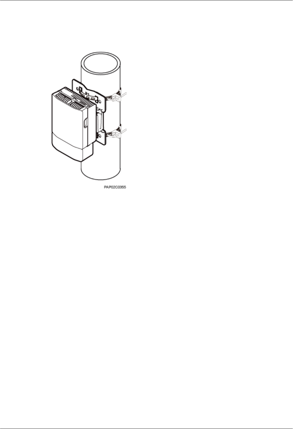
Figure 3-5 shows the BTS3902E installed on a metal pole.
Figure 3-5 BTS3902E installed on a metal pole
On a Wall
The wall on which a BTS3902E is installed must meet the following requirements:
lWhen a single BTS3902E is installed, the wall must have a capacity of bearing at least four
times the weight of the BTS3902E.
lExpansion bolts must be tightened to 30 N·m (265.52 lbf·in.) to ensure the bolts work
properly and the wall remains intact without cracks in it.
Figure 3-6 shows the BTS3902E installed on a wall.
BTS3902E WCDMA
Installation Guide 3 Information About the Installation
Issue 10 (2014-05-16) Huawei Proprietary and Confidential
Copyright © Huawei Technologies Co., Ltd.
12
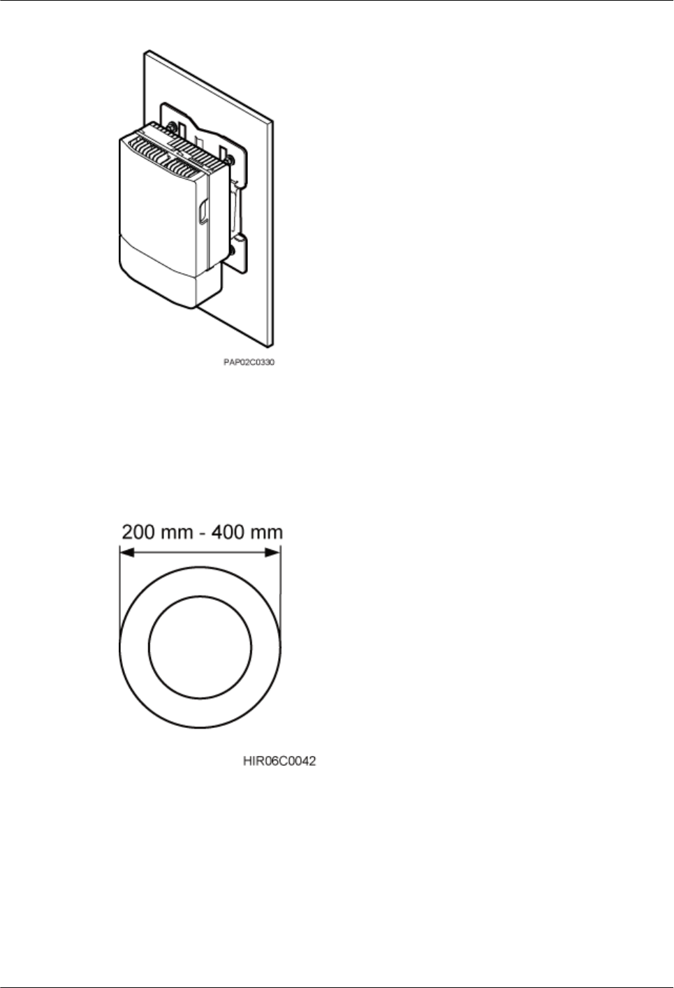
Figure 3-6 BTS3902E installed on a wall
On a Wood Pole with the Diameter Ranging from 200 mm to 400 mm (7.87 in. to
15.75 in.)
Figure 3-7 shows the BTS3902E installed on a wood pole.
Figure 3-7 Diameter of a pole
Figure 3-8 shows a BTS3902E installed on a wood pole.
BTS3902E WCDMA
Installation Guide 3 Information About the Installation
Issue 10 (2014-05-16) Huawei Proprietary and Confidential
Copyright © Huawei Technologies Co., Ltd.
13
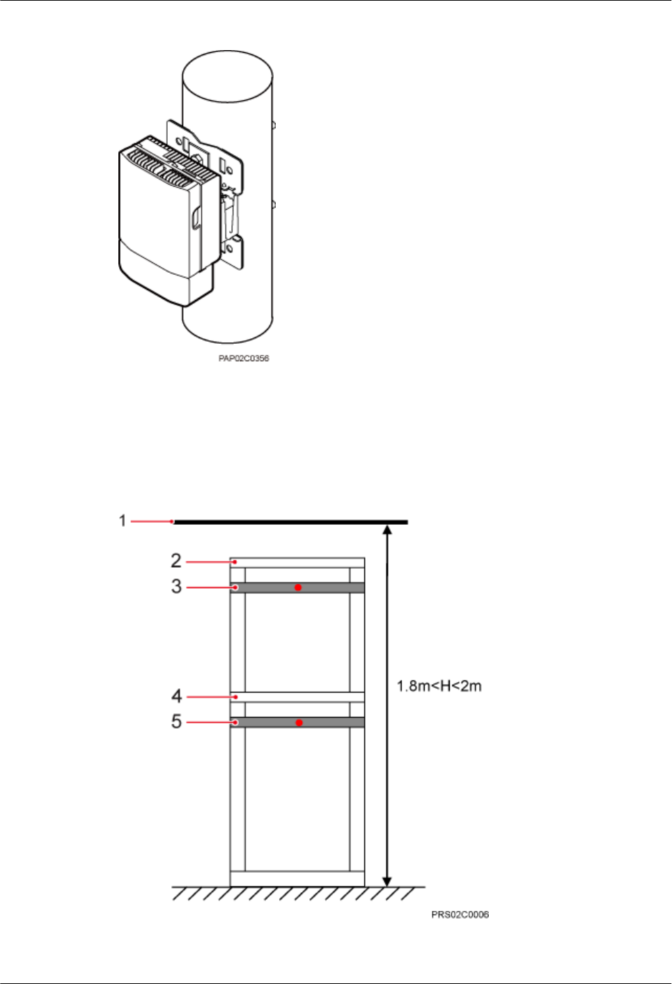
Figure 3-8 BTS3902E installed on a wood pole
On an IFS06 Under a Cable Tray with a Restricted Height
In the scenario where a cable tray is 1.8 m to 2 m (5.91 ft. to 6.56 ft.) above the floor (height-
restricted scenario), BTS3902Es are installed on beam 2 and beam 4, as shown in Figure 3-9.
Figure 3-9 Height-restricted scenario
(1) Cable tray (2) Beam 1 (3) Beam 2 (4) Beam 3 (5) Beam 4
BTS3902E WCDMA
Installation Guide 3 Information About the Installation
Issue 10 (2014-05-16) Huawei Proprietary and Confidential
Copyright © Huawei Technologies Co., Ltd.
14
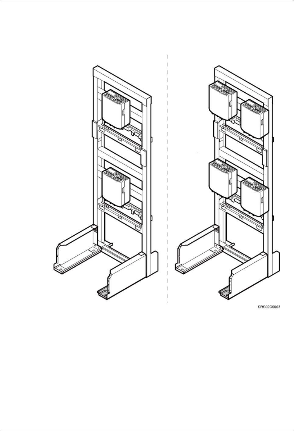
Figure 3-10 shows BTS3902Es installed on an IFS06 under a cable tray with a restricted height.
Figure 3-10 BTS3902Es installed on an IFS06 under a cable tray with a restricted height
On an IFS06 Under a Cable Tray with an Unrestricted Height
In the scenario where a cable tray is more than 2 m (6.56 ft.) above the floor (height-unrestricted
scenario), BTS3902Es are installed on beam 1 and beam 3 by default, as shown in Figure
3-11.
BTS3902E WCDMA
Installation Guide 3 Information About the Installation
Issue 10 (2014-05-16) Huawei Proprietary and Confidential
Copyright © Huawei Technologies Co., Ltd.
15
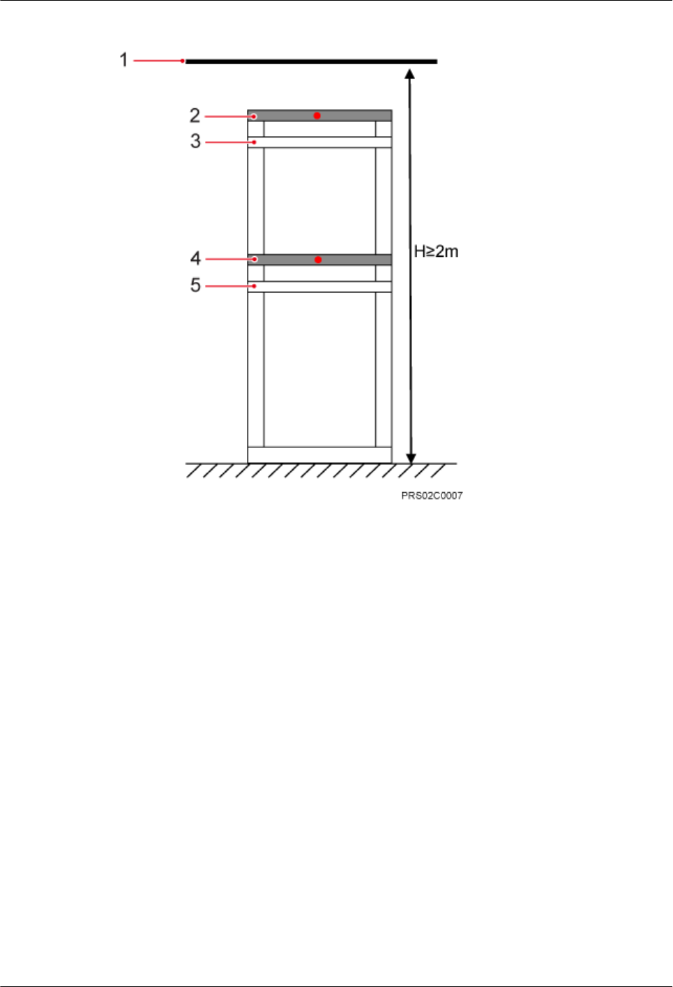
Figure 3-11 Height-unrestricted scenario
(1) Cable tray (2) Beam 1 (3) Beam 2 (4) Beam 3 (5) Beam 4
Figure 3-12 shows BTS3902Es installed on an IFS06 under a cable tray with an unrestricted
height.
BTS3902E WCDMA
Installation Guide 3 Information About the Installation
Issue 10 (2014-05-16) Huawei Proprietary and Confidential
Copyright © Huawei Technologies Co., Ltd.
16
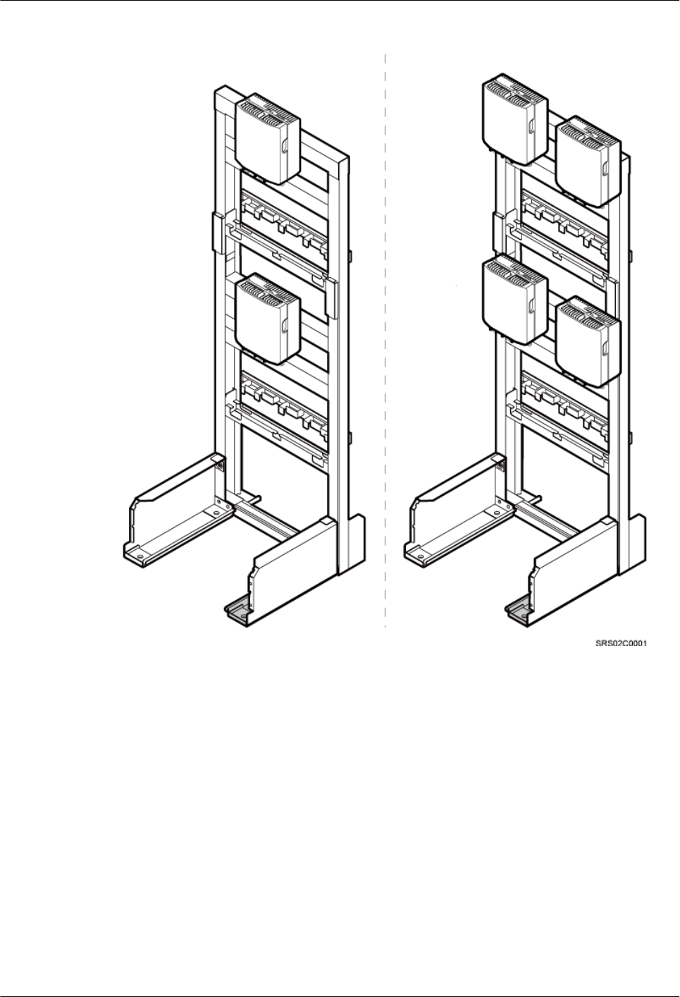
Figure 3-12 BTS3902Es installed on an IFS06 under a cable tray with an unrestricted height
3.3 Installation Clearance Requirements
This section describes the clearance requirements for installing a BTS3902E on a metal pole,
wood pole, wall, or IFS06.
Figure 3-13 shows the recommended clearance for installing a single BTS3902E.
BTS3902E WCDMA
Installation Guide 3 Information About the Installation
Issue 10 (2014-05-16) Huawei Proprietary and Confidential
Copyright © Huawei Technologies Co., Ltd.
17
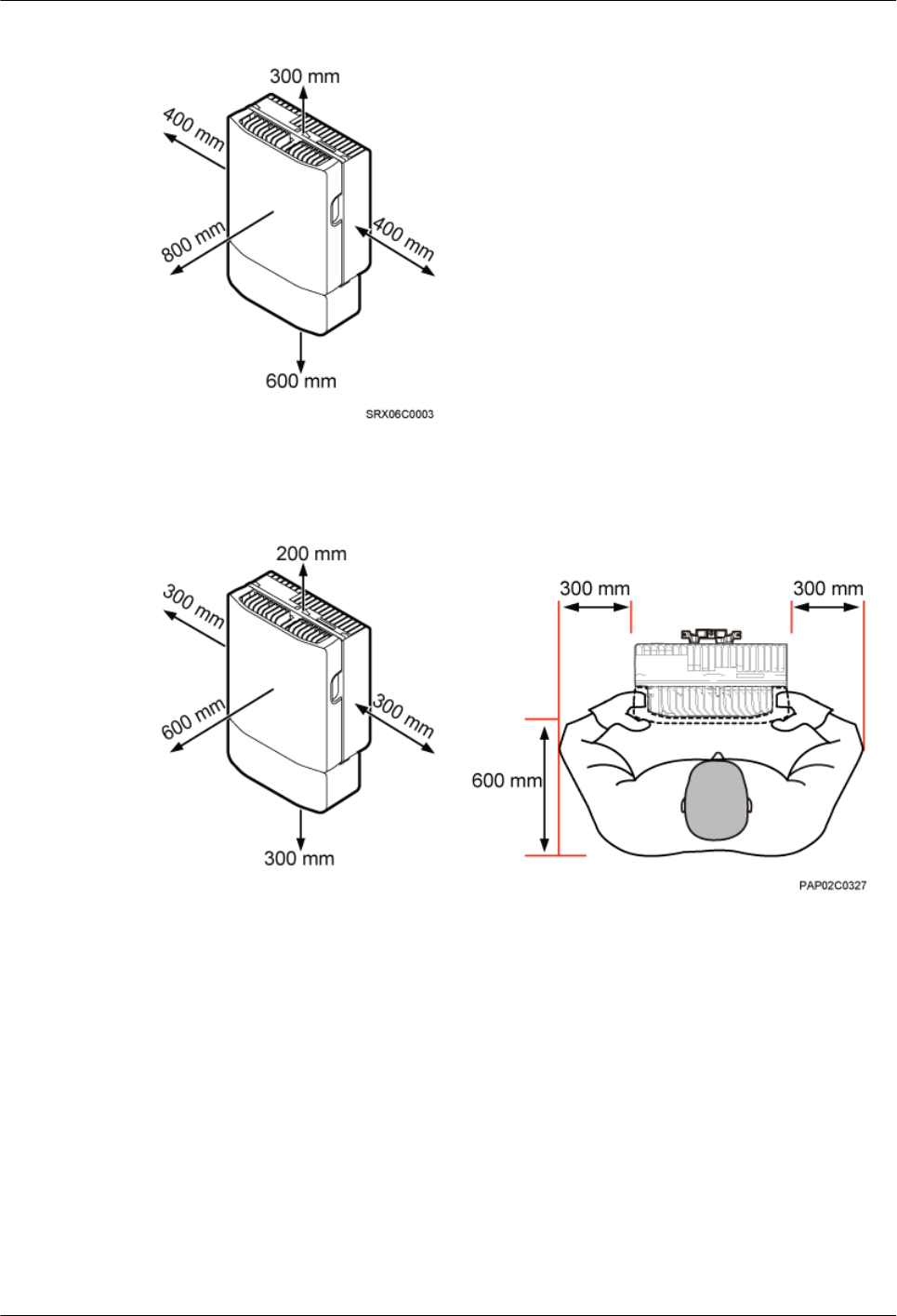
Figure 3-13 Recommended clearance for installing a single BTS3902E
Figure 3-14 shows the minimum clearance for installing a single BTS3902E.
Figure 3-14 Minimum clearance for installing a single BTS3902E
Figure 3-15 shows the recommended clearance for installing two BTS3902Es side by side.
BTS3902E WCDMA
Installation Guide 3 Information About the Installation
Issue 10 (2014-05-16) Huawei Proprietary and Confidential
Copyright © Huawei Technologies Co., Ltd.
18
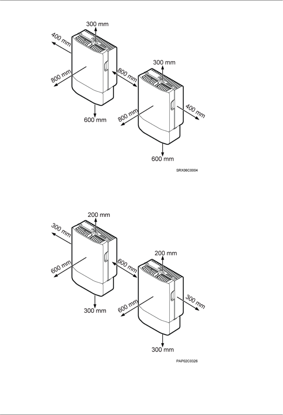
Figure 3-15 Recommended clearance for installing two BTS3902Es side by side
Figure 3-16 shows the minimum clearance for installing two BTS3902Es side by side.
Figure 3-16 Minimum clearance for installing two BTS3902Es side by side
Figure 3-17 shows the recommended clearance for installing two BTS3902Es in a vertical line.
BTS3902E WCDMA
Installation Guide 3 Information About the Installation
Issue 10 (2014-05-16) Huawei Proprietary and Confidential
Copyright © Huawei Technologies Co., Ltd.
19
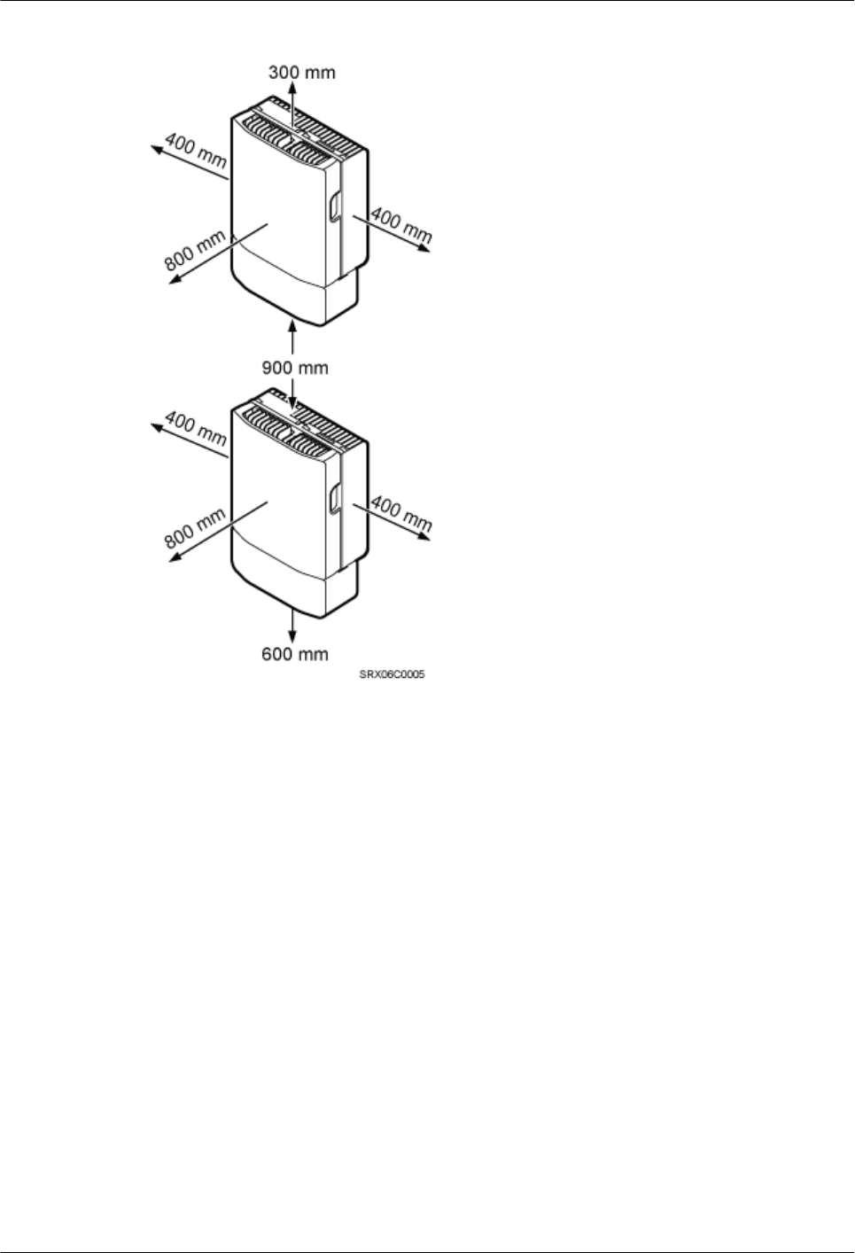
Figure 3-17 Recommended clearance for installing two BTS3902Es in a vertical line
Figure 3-18 shows the minimum clearance for installing two BTS3902Es in a vertical line.
BTS3902E WCDMA
Installation Guide 3 Information About the Installation
Issue 10 (2014-05-16) Huawei Proprietary and Confidential
Copyright © Huawei Technologies Co., Ltd.
20

Figure 3-18 Minimum clearance for installing two BTS3902Es in a vertical line
Figure 3-19 shows the recommended clearance for installing two BTS3902Es on an IFS06.
BTS3902E WCDMA
Installation Guide 3 Information About the Installation
Issue 10 (2014-05-16) Huawei Proprietary and Confidential
Copyright © Huawei Technologies Co., Ltd.
21
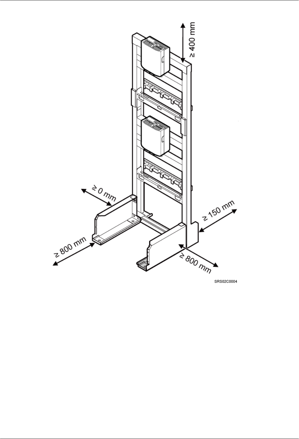
Figure 3-19 Recommended clearance for installing two BTS3902Es on an IFS06
Figure 3-20 shows the minimum clearance for installing two BTS3902Es on an IFS06.
BTS3902E WCDMA
Installation Guide 3 Information About the Installation
Issue 10 (2014-05-16) Huawei Proprietary and Confidential
Copyright © Huawei Technologies Co., Ltd.
22
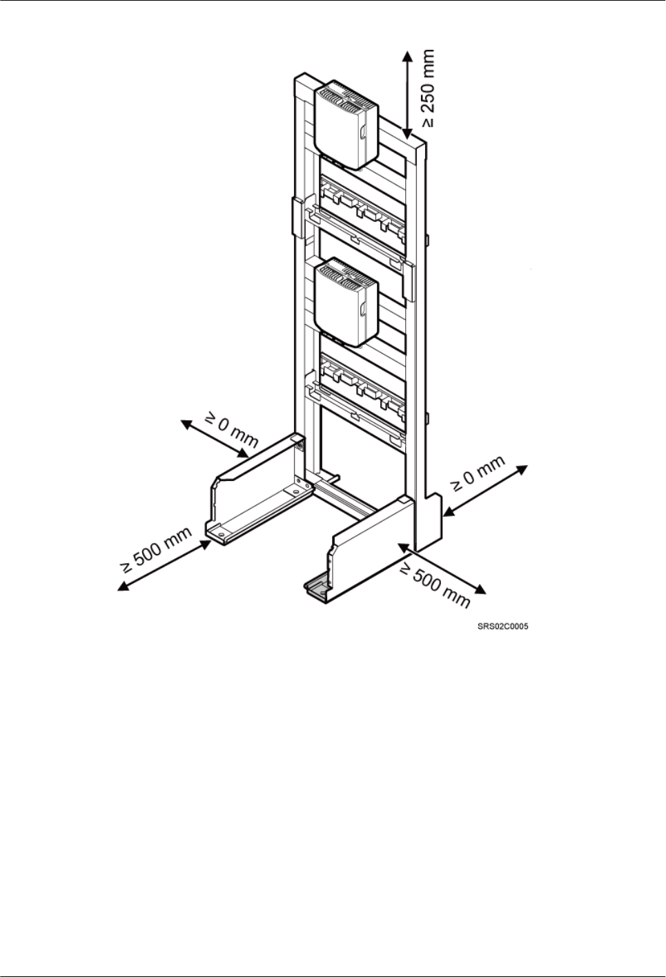
Figure 3-20 Minimum clearance for installing two BTS3902Es on an IFS06
3.4 Mounting Kits for Installing a BTS3902E
This section describes the mounting kits for a BTS3902E and the precautions for hoisting the
BTS3902E.
Aluminum Mounting Kits
An aluminum mounting kit consists of an attachment plate and mounting brackets. It is used for
installing a BTS3902E with the external antenna.
lAttachment plate
Figure 3-21 shows the attachment plate of an aluminum mounting kit.
BTS3902E WCDMA
Installation Guide 3 Information About the Installation
Issue 10 (2014-05-16) Huawei Proprietary and Confidential
Copyright © Huawei Technologies Co., Ltd.
23
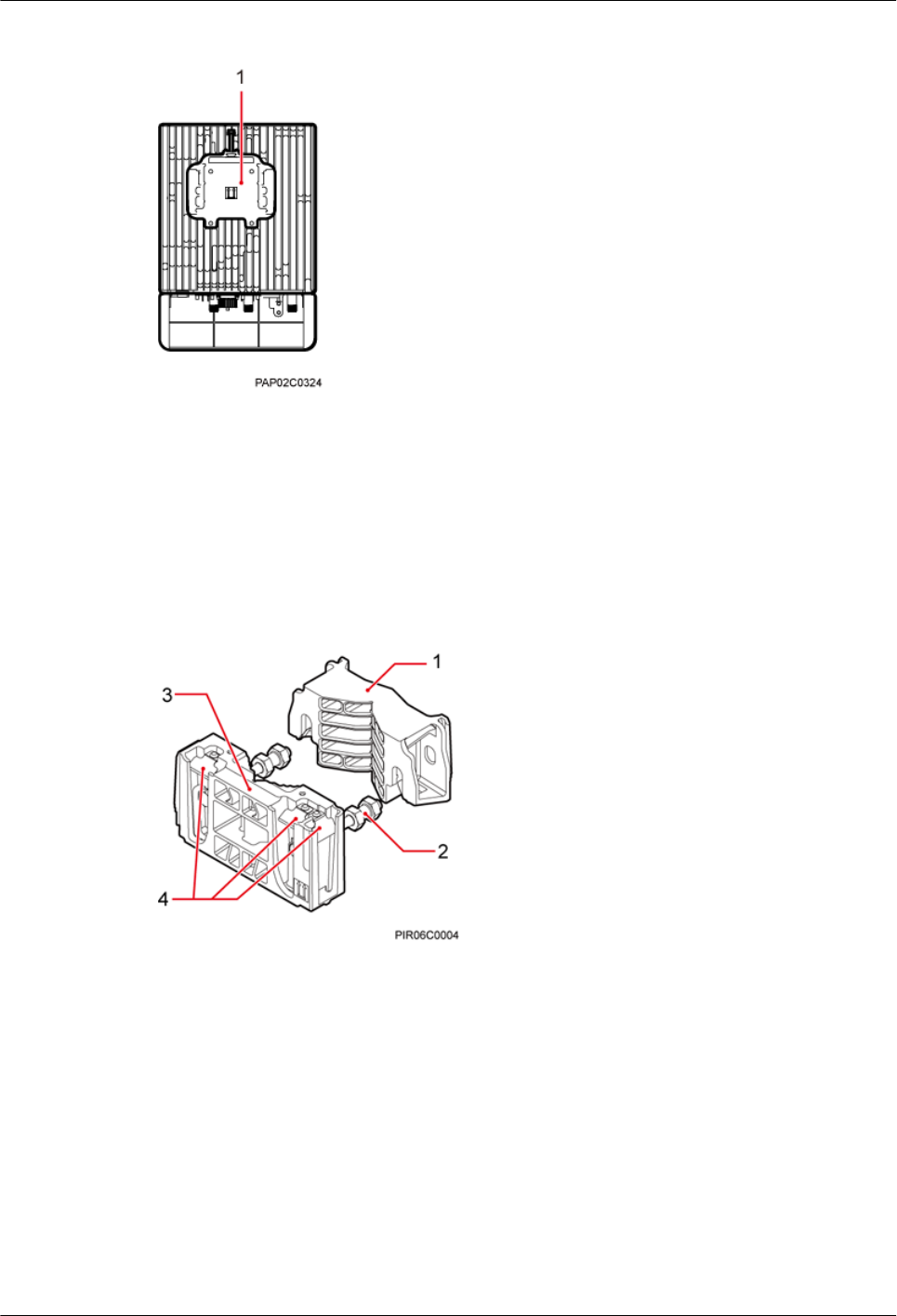
Figure 3-21 Attachment plate of an aluminum mounting kit
(1) Attachment plate
lMounting bracket assembly
Figure 3-22 shows the mounting bracket assembly of an aluminum mounting kit.
Figure 3-22 Mounting bracket assembly of an aluminum mounting kit
(1) Auxiliary mounting
bracket
(2) double-headed nut (3) Main mounting bracket (4) Hoist clamp on the main
mounting bracket
Angle-Adjustable Mounting Kits
The angle-adjustable mounting kits are applied to install a BTS3902E with the embedded
antenna and consists of attachment plates and mounting brackets.
lAttachment plate
Figure 3-23 shows the attachment plate of the angle-adjustable mounting kits.
BTS3902E WCDMA
Installation Guide 3 Information About the Installation
Issue 10 (2014-05-16) Huawei Proprietary and Confidential
Copyright © Huawei Technologies Co., Ltd.
24
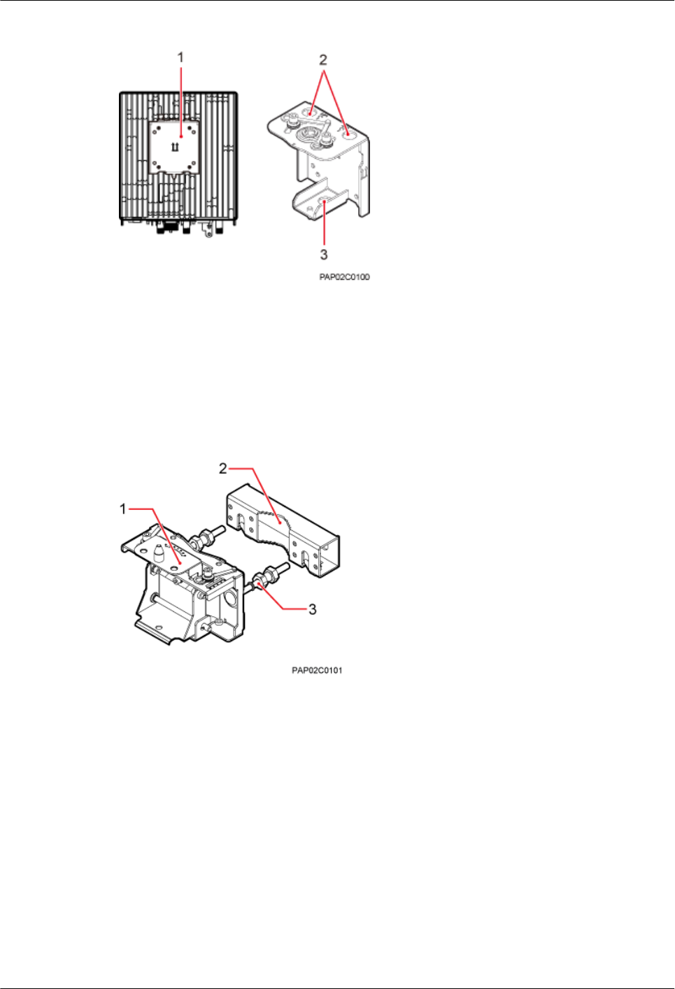
Figure 3-23 Attachment plate of the angle-adjustable mounting kits
(1) Attachment plate (2) Lifting eye (3) Traction eye
lMounting bracket assembly
Figure 3-24 shows the mounting bracket assembly of the BTS3902E.
Figure 3-24 Mounting bracket assembly of the angle-adjustable mounting kits
(1) Main mounting bracket (2) Auxiliary mounting bracket (3) double-headed nut
Adapting plate
Figure 3-24 shows the adapting plate assembly of the BTS3902E.
BTS3902E WCDMA
Installation Guide 3 Information About the Installation
Issue 10 (2014-05-16) Huawei Proprietary and Confidential
Copyright © Huawei Technologies Co., Ltd.
25
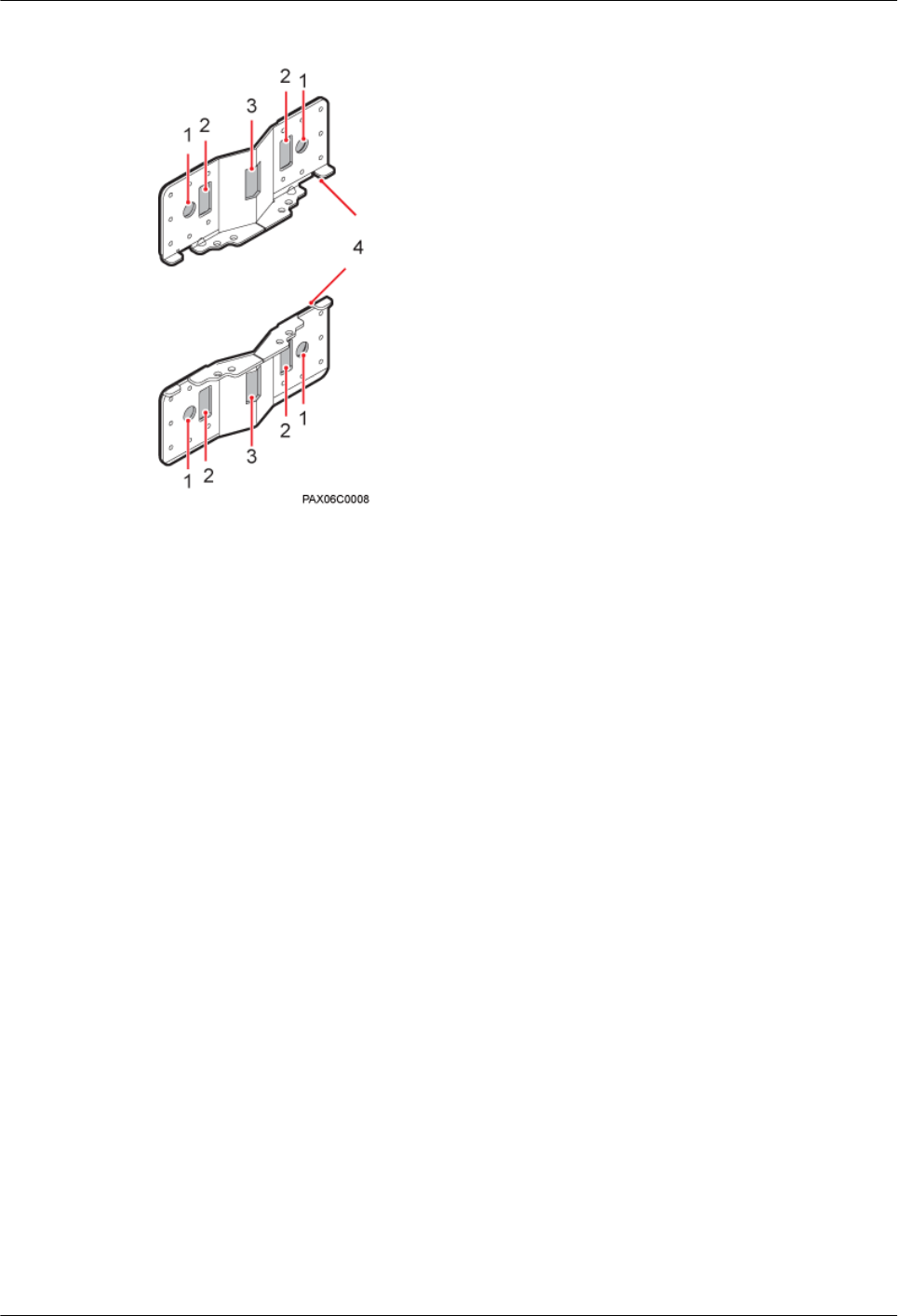
Figure 3-25 BTS3902E adapting plate assembly
(1) Mounting hole group A (2) Mounting hole group B (3) Mounting hole group C (4) Adapting plate
Precautions for Hoisting a BTS3902E
When hoisting the BTS3902E, pay attention to the following points.
lEnsure that the housing of the BTS3902E is securely installed before hoisting. When
hoisting a BTS3902E with an embedded antenna, prevent the antenna from colliding with
the tower.
lPlace a foam pad or cardboard on the ground to protect the housing of the BTS3902E from
damage before binding the BTS3902E with a lifting sling. Do not stand the BTS3902E
upright on the ground because the bottom of the BTS3902E cannot bear much weight.
BTS3902E WCDMA
Installation Guide 3 Information About the Installation
Issue 10 (2014-05-16) Huawei Proprietary and Confidential
Copyright © Huawei Technologies Co., Ltd.
26
4 Unpacking the Equipment
Unpack and check the delivered equipment to ensure that all the materials are included and intact.
Prerequisites
NOTICE
The base station must be powered on within 24 hours after it is unpacked, and the period for
which the base station remains powered-off during maintenance must not exceed 24 hours.
Context
NOTE
When transporting, moving, or installing the equipment, components, or parts, you must:
lPrevent them from colliding with doors, walls, shelves, or other objects.
lWear clean gloves, and avoid touching the equipment, components, or parts with bare hands, sweat-
soaked gloves, or dirty gloves.
Procedure
Step 1 Check the total number of articles in each case according to the packing list.
If ... Then ...
The total number tallies with the packing
list
Go to Step 2.
The total number does not tally with the
packing list
Find out the cause and report any missing
articles to the local Huawei office.
Step 2 Check the exterior of the packing case.
BTS3902E WCDMA
Installation Guide 4 Unpacking the Equipment
Issue 10 (2014-05-16) Huawei Proprietary and Confidential
Copyright © Huawei Technologies Co., Ltd.
27
If ... Then ...
The outer packing is intact Go to Step 3.
The outer packing is severely damaged or
soaked
Find out the cause and report it to the local
Huawei office.
Step 3 Check the type and quantity of the equipment in the cases according to the packing list.
If ... Then ...
Types and quantity of the article tally with
those on the packing list
Sign the Packing List with the customer.
There is any shipment shortage or wrong
shipment
Fill in and submit the Cargo Shortage and
Mishandling Report.
Articles are damaged. Fill in and submit the Article Replacement
Report.
NOTICE
To protect the equipment and prevent damage to the equipment, you are advised to keep the
unpacked equipment and packing materials indoors, take photos of the stocking environment,
packing case or carton, packing materials, and any rusted or eroded equipment, and then file the
photos.
----End
BTS3902E WCDMA
Installation Guide 4 Unpacking the Equipment
Issue 10 (2014-05-16) Huawei Proprietary and Confidential
Copyright © Huawei Technologies Co., Ltd.
28
5 Obtaining the ESN
The Electronic Serial Number (ESN) is a unique identifier of a device. It is used during base
station commissioning. Therefore, record the ESN before installing the BTS3902E.There are
two types of the BTS3902E. This document uses one type as the example to describe.
Procedure
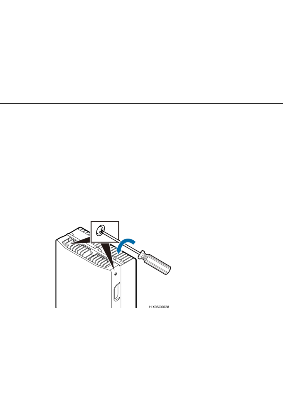
Step 1 Use an M4 Phillips screwdriver to loosen the two captive screws from the upper housing, as
shown in Figure 5-1.
Figure 5-1 Loosening the screws from the housing
Step 2 Move the upper housing until it is stopped, as shown in Figure 5-2.
BTS3902E WCDMA
Installation Guide 5 Obtaining the ESN
Issue 10 (2014-05-16) Huawei Proprietary and Confidential
Copyright © Huawei Technologies Co., Ltd.
29
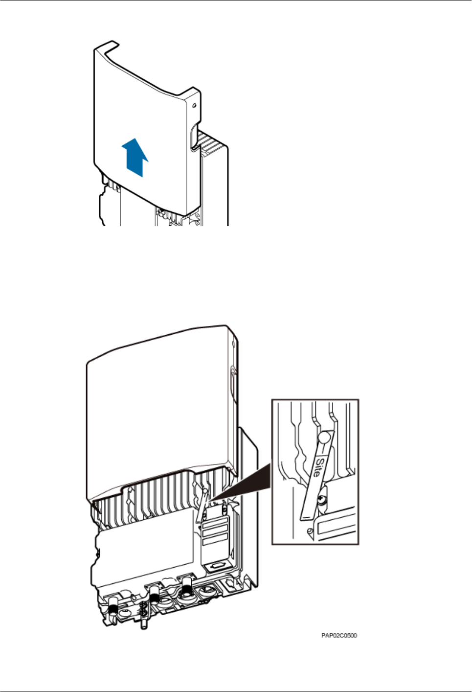
Figure 5-2 Moving the upper housing
Step 3 Record the ESN on the BTS3902E.
The ESN is printed on the label and on the BTS3902E. You need to take the label with the site
information, as shown in Figure 5-3.
Figure 5-3 Obtaining the ESN
BTS3902E WCDMA
Installation Guide 5 Obtaining the ESN
Issue 10 (2014-05-16) Huawei Proprietary and Confidential
Copyright © Huawei Technologies Co., Ltd.
30

Step 4 Report the ESN to the engineer for the commissioning of the base station.
Step 5 Close the housing according to the instructions in 11.2 Installing the Upper Housing.
----End
BTS3902E WCDMA
Installation Guide 5 Obtaining the ESN
Issue 10 (2014-05-16) Huawei Proprietary and Confidential
Copyright © Huawei Technologies Co., Ltd.
31

6 Installation Process
This chapter describes the procedures for installing the BTS3902E. The procedures involve
installing a BTS3902E, installing BTS3902E cables, checking the BTS3902E hardware
installation, and powering on the BTS3902E.
Figure 6-1 shows the installation procedure.
NOTE
If you conduct a power-on check on the cabinet, you can install the housing after the power-on check is complete.
The following figure shows the procedures in which checking the power-on status is after installing the housing.
BTS3902E WCDMA
Installation Guide 6 Installation Process
Issue 10 (2014-05-16) Huawei Proprietary and Confidential
Copyright © Huawei Technologies Co., Ltd.
32
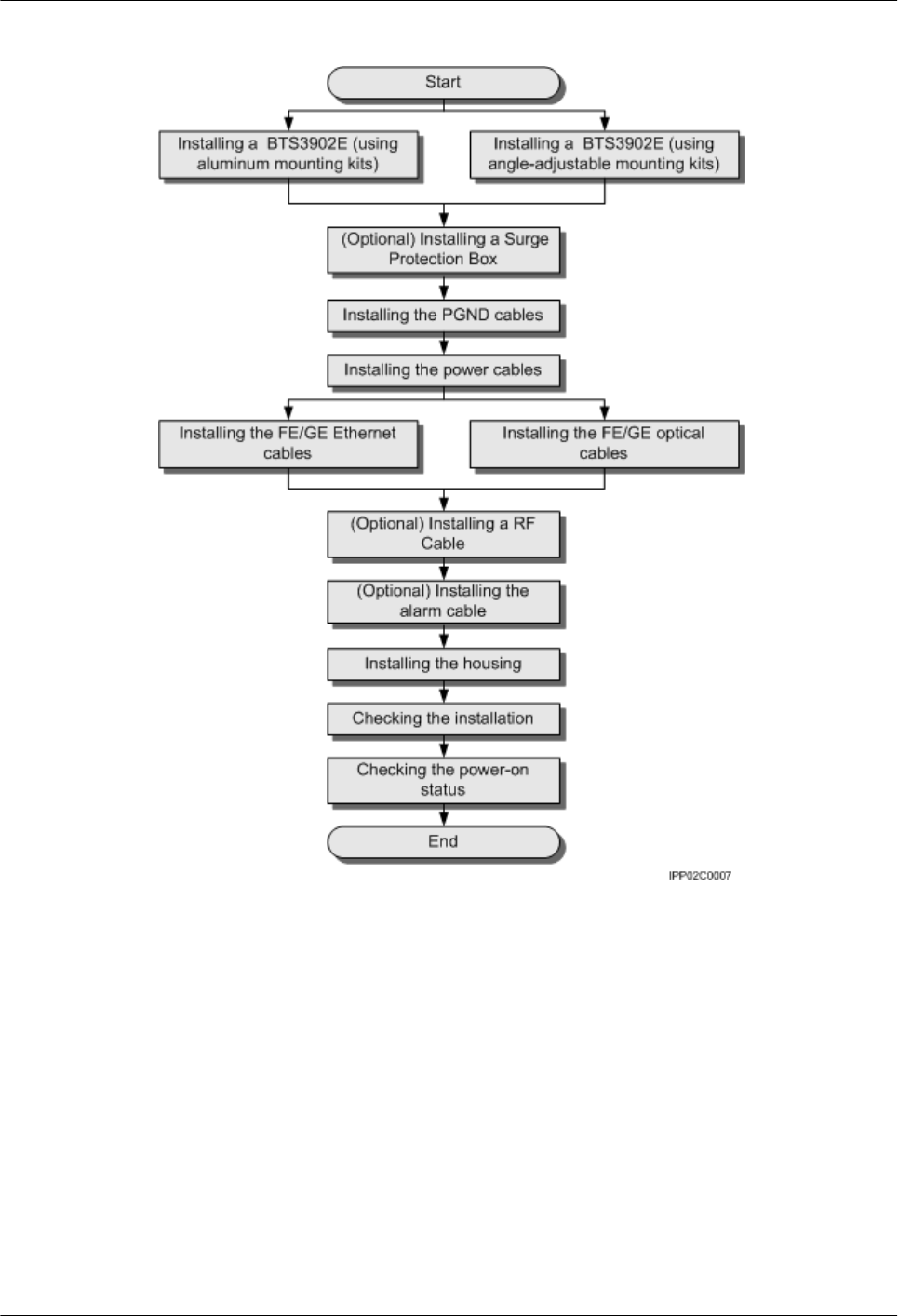
Figure 6-1 Process of installing a BTS3902E
BTS3902E WCDMA
Installation Guide 6 Installation Process
Issue 10 (2014-05-16) Huawei Proprietary and Confidential
Copyright © Huawei Technologies Co., Ltd.
33

7 Installing a BTS3902E (using aluminum
mounting kits)
About This Chapter
This chapter describes the procedure for installing a BTS3902E with an external antenna, when
an aluminum mounting kit is used. The BTS3902E can be installed on a metal pole, wall, wood
pole, or IFS06 in different scenarios.
7.1 Installing a BTS3902E on a Pole with the Diameter of 60 mm to 114 mm (2.36 in. to 4.49
in.)
This section describes the procedure and precautions for installing a BTS3902E on a pole with
the diameter of 60 mm to 114 mm (2.36 in. to 4.49 in.).
7.2 Installing a BTS3902E on a Pole with the Diameter of 114 mm to 400 mm (4.49 in. to 15.75
in.)
This section describes the procedure and precautions for installing a BTS3902E on a pole with
the diameter of 114 mm to 400 mm (4.49 in. to 15.75 in.).
7.3 Installing a BTS3902E on a Wall
This section describes the procedure and precautions for installing a BTS3902E on a wall.
7.4 Installing a BTS3902E on a Wood Pole with the Diameter of 200 mm to 400 mm (7.87 in.
to 15.75 in.)
This section describes the procedure and precautions for installing a BTS3902E on a wood pole.
7.5 Installing BTS3902Es on an IFS06
This section describes the procedure and precautions for installing BTS3902Es on an IFS06.
BTS3902E WCDMA
Installation Guide 7 Installing a BTS3902E (using aluminum mounting kits)
Issue 10 (2014-05-16) Huawei Proprietary and Confidential
Copyright © Huawei Technologies Co., Ltd.
34
7.1 Installing a BTS3902E on a Pole with the Diameter of 60
mm to 114 mm (2.36 in. to 4.49 in.)
This section describes the procedure and precautions for installing a BTS3902E on a pole with
the diameter of 60 mm to 114 mm (2.36 in. to 4.49 in.).
Procedure
Step 1 Determine the position for installing the main mounting bracket.
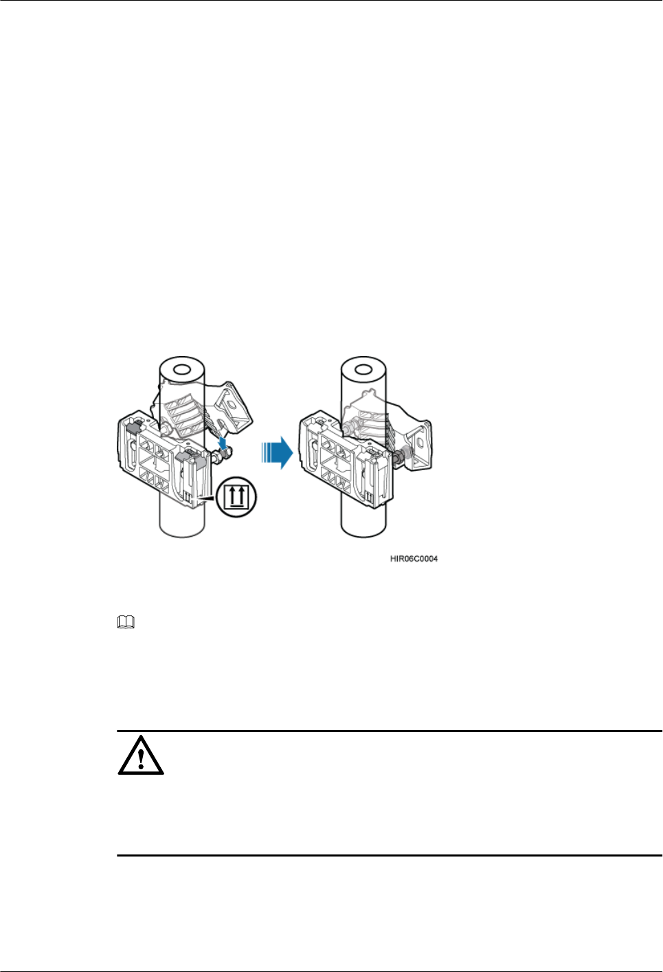
Step 2 Fit one end of the auxiliary bracket to one double-headed nut assembly of the main bracket.
Step 3 Install the bracket assembly on the pole, and then fit the other end of the auxiliary bracket to the
other double-headed nut assembly, as shown in Figure 7-1.
Figure 7-1 Installing the bracket assembly
NOTE
Verify that the arrow on the main bracket is pointing up.
Step 4 Using a torque wrench, tighten the nuts to 40 N·m (354.03 lbf·in.) to secure the bracket assembly
onto the pole, as shown in Figure 7-2.
NOTICE
Tighten the two double-headed nut assemblies alternatively. After the main and auxiliary
brackets are secured properly, measure the spacing between the brackets on both sides and ensure
that the spacing is the same on the two sides.
BTS3902E WCDMA
Installation Guide 7 Installing a BTS3902E (using aluminum mounting kits)
Issue 10 (2014-05-16) Huawei Proprietary and Confidential
Copyright © Huawei Technologies Co., Ltd.
35
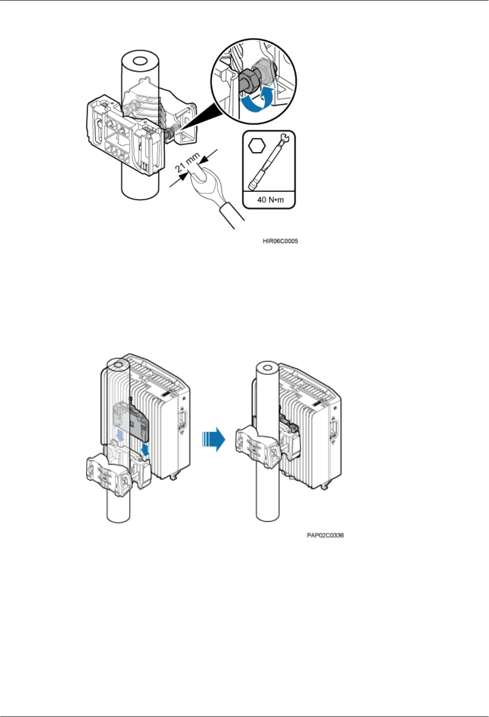
Figure 7-2 Securing the bracket assembly onto the pole
Step 5 Install the BTS3902E onto the main mounting bracket until the BTS3902E snaps shut, as shown
in Figure 7-3.
Figure 7-3 Installing the BTS3902E onto the main mounting bracket
----End
7.2 Installing a BTS3902E on a Pole with the Diameter of 114
mm to 400 mm (4.49 in. to 15.75 in.)
This section describes the procedure and precautions for installing a BTS3902E on a pole with
the diameter of 114 mm to 400 mm (4.49 in. to 15.75 in.).
BTS3902E WCDMA
Installation Guide 7 Installing a BTS3902E (using aluminum mounting kits)
Issue 10 (2014-05-16) Huawei Proprietary and Confidential
Copyright © Huawei Technologies Co., Ltd.
36
Procedure
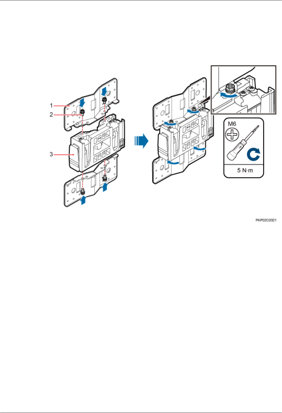
Step 1 Install an adapting plate both on the top and bottom of the main mounting bracket. Tighten two
M6x14 screws to 5 N·m (44.25 lbf·in.) to secure each of the plates, as shown in Figure 7-4.
Figure 7-4 Installing the adapting plate assembly
(1) Adapting plate (2) Screw (3) Main mounting bracket
Step 2 Install two hose clamps through the mounting hole group B on the adapting plates, as shown in
Figure 7-5.
BTS3902E WCDMA
Installation Guide 7 Installing a BTS3902E (using aluminum mounting kits)
Issue 10 (2014-05-16) Huawei Proprietary and Confidential
Copyright © Huawei Technologies Co., Ltd.
37
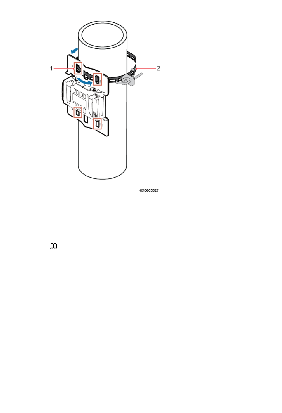
Figure 7-5 Installing the hose clamps through the mounting hole group B
(1) Mounting hole group B (2) Hose clamp
Step 3 Install the mounting piece, as shown in Figure 7-6.
1. Tighten the M12 screws to 30 N·m (265.52 lbf·in.)
2. Use a level to check whether the adapting plate is on a horizontal plane.
NOTE
Secure the upper hose clamp before securing the lower clamp.
BTS3902E WCDMA
Installation Guide 7 Installing a BTS3902E (using aluminum mounting kits)
Issue 10 (2014-05-16) Huawei Proprietary and Confidential
Copyright © Huawei Technologies Co., Ltd.
38
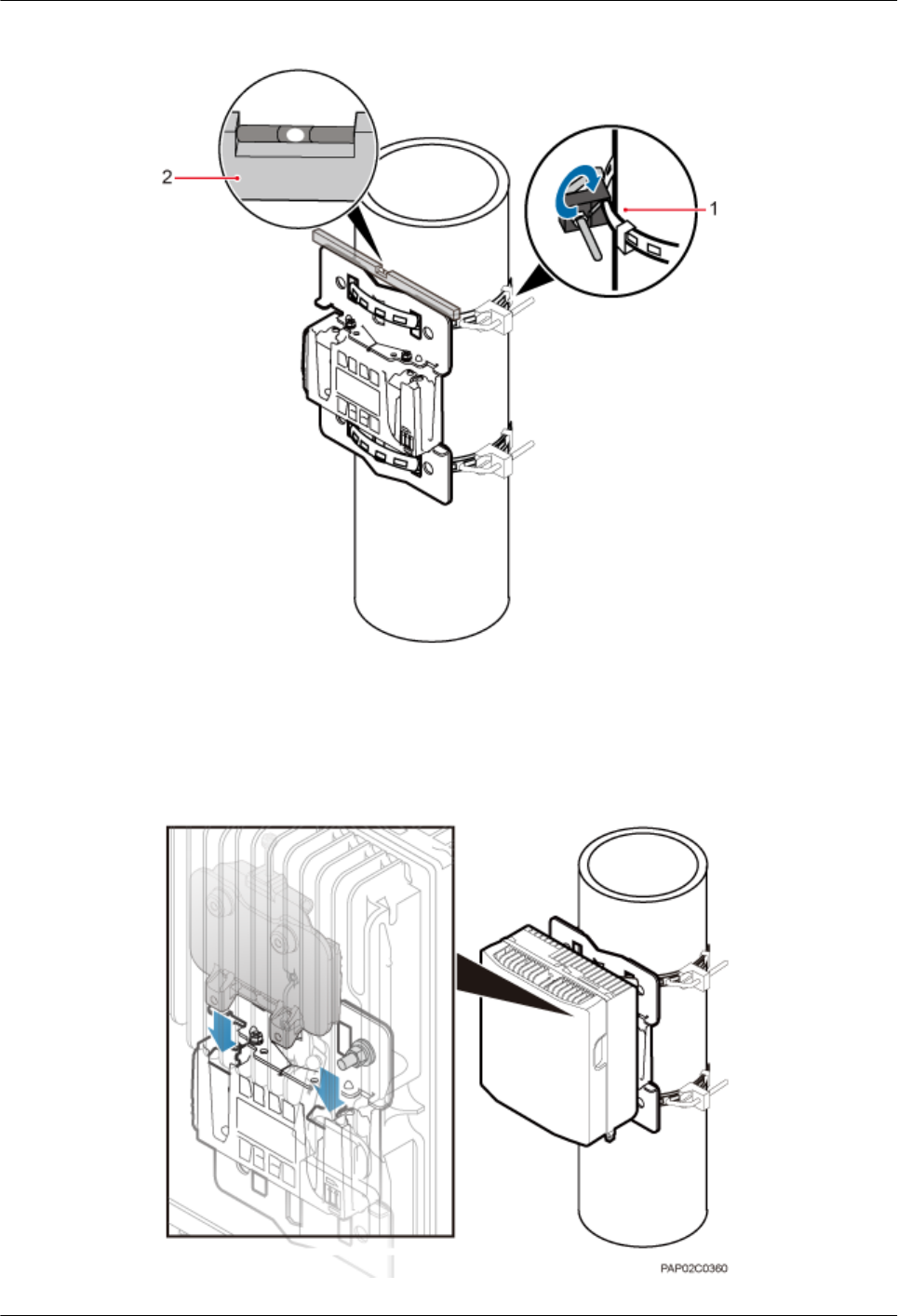
Figure 7-6 Securing the hose clamps
(1) Hose clamp (2) Level
Step 4 Install the BTS3902E onto the main mounting bracket until the BTS3902E snaps shut, as shown
in Figure 7-7.
Figure 7-7 Installing the BTS3902E onto the main mounting bracket
BTS3902E WCDMA
Installation Guide 7 Installing a BTS3902E (using aluminum mounting kits)
Issue 10 (2014-05-16) Huawei Proprietary and Confidential
Copyright © Huawei Technologies Co., Ltd.
39
----End
7.3 Installing a BTS3902E on a Wall
This section describes the procedure and precautions for installing a BTS3902E on a wall.
Context
NOTICE
You must use adjustable torque tools to tighten all the screws and nuts to the required torque
described in this document.
Procedure
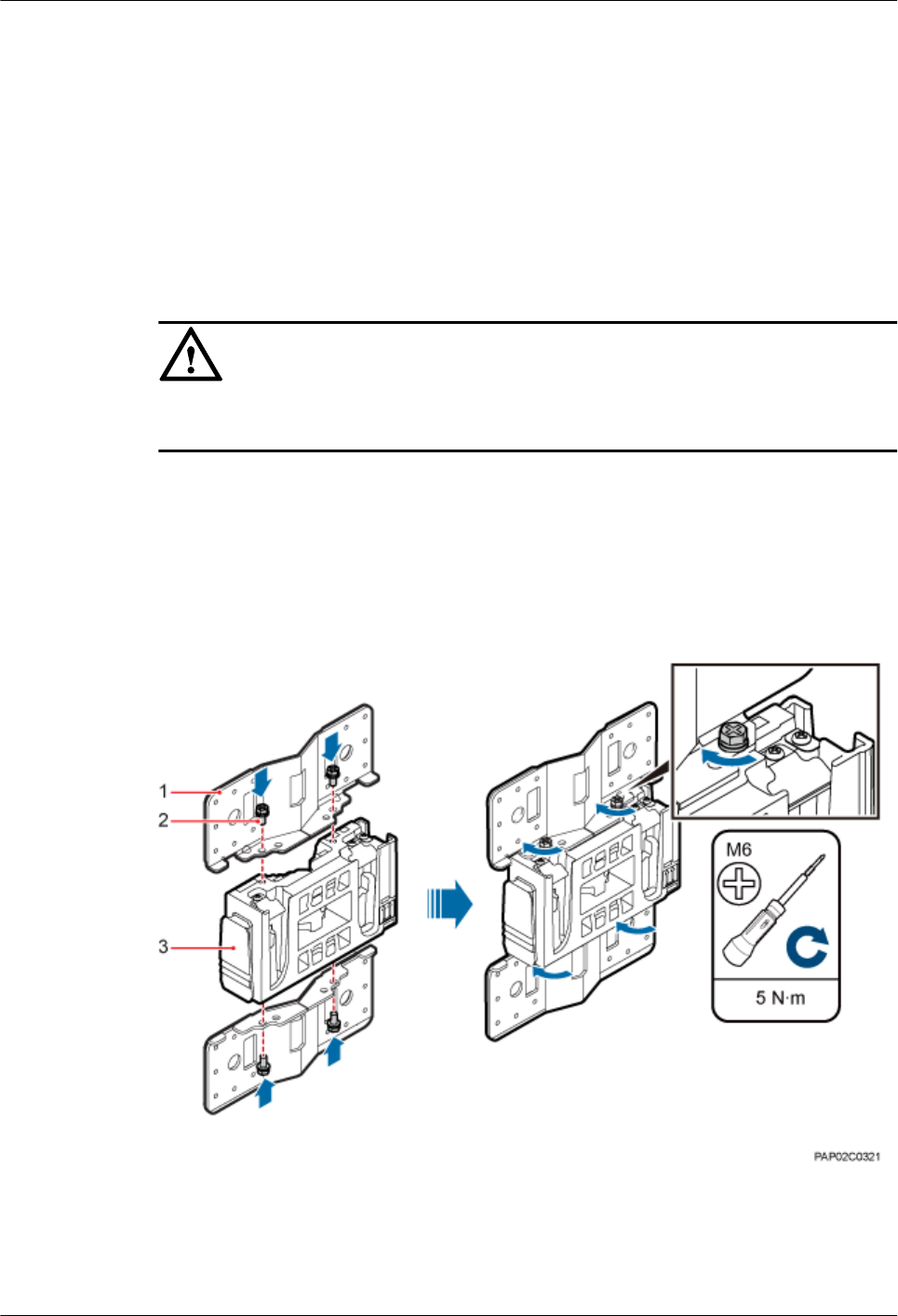
Step 1 Install an adapting plate both on the top and bottom of the main mounting bracket. Tighten two
M6x14 screws to 5 N·m (44.25 lbf·in.) to secure each of the plates, as shown in Figure 7-8.
Figure 7-8 Installing the adapting plate assembly
(1) Adapting plate (2) Screw (3) Main mounting bracket
Step 2 Place the adapting plates against the wall, use a level to verify that the plates are horizontal, and
then use a marker to mark anchor points, as shown in Figure 7-9.
BTS3902E WCDMA
Installation Guide 7 Installing a BTS3902E (using aluminum mounting kits)
Issue 10 (2014-05-16) Huawei Proprietary and Confidential
Copyright © Huawei Technologies Co., Ltd.
40
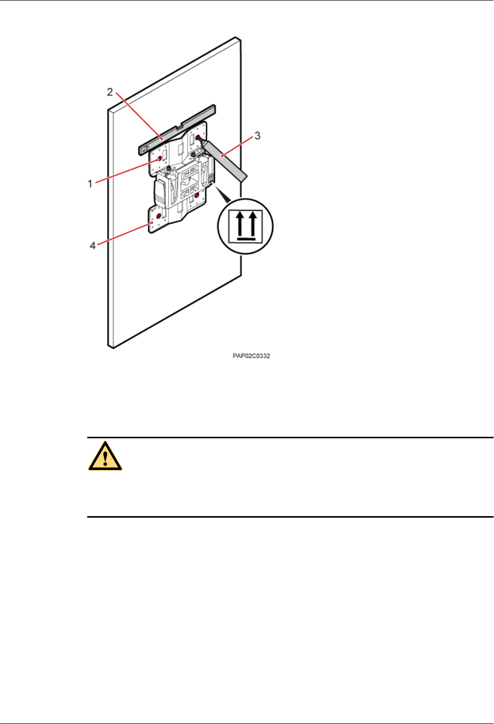
Figure 7-9 Marking anchor points
(1) Mounting hole group A (2) Level (3) Marker (4) Adapting plate
CAUTION
To prevent inhalation or eye contact with dust, take adequate preventive measures when drilling
holes.
Step 3 Drill holes at the anchor points, and then install expansion bolt assemblies, as shown in Figure
7-10.
BTS3902E WCDMA
Installation Guide 7 Installing a BTS3902E (using aluminum mounting kits)
Issue 10 (2014-05-16) Huawei Proprietary and Confidential
Copyright © Huawei Technologies Co., Ltd.
41

Figure 7-10 Drilling holes and install expansion bolt assemblies
(1) M10x80 bolt (2) Nut (3) Spring washer (4) Flat washer (5) Expansion tube
1. Use a hammer drill with a φ12 bit to drill holes perpendicularly with the wall at the marked
anchor points. Ensure that the depth of each hole ranges from 55 mm to 60 mm (2.17 in.
to 2.36 in.) and each hole is of the same depth.
2. Use a vacuum cleaner to clear dust inside and around the holes, and then measure the inter-
hole spacing. If the spacing is too wide or too narrow, drill holes again.
3. Tighten each expansion bolt slightly and place them perpendicularly into each hole.
4. Hit each expansion bolt using a rubber mallet to enable the expansion tube to enter the hole
completely.
5. Remove the M10x80 bolt, nut, spring washer, and flat washer from each expansion bolt
assembly in sequence.
NOTICE
After dismantling an expansion bolt assembly, ensure that the top of the expansion tube is
on the same level as the wall. Otherwise, the device cannot be installed on the wall evenly
and securely.
Step 4 Fit the mounting piece on the expansion bolt, and then use a combination wrench (with a size
of 17 mm or 0.67 in.) to tighten the expansion bolts to 25 N·m (265.52 lbf·in.), as shown in
Figure 7-11.
NOTICE
Ensure that the arrow on the main mounting bracket points upwards when installing the mounting
piece.
BTS3902E WCDMA
Installation Guide 7 Installing a BTS3902E (using aluminum mounting kits)
Issue 10 (2014-05-16) Huawei Proprietary and Confidential
Copyright © Huawei Technologies Co., Ltd.
42
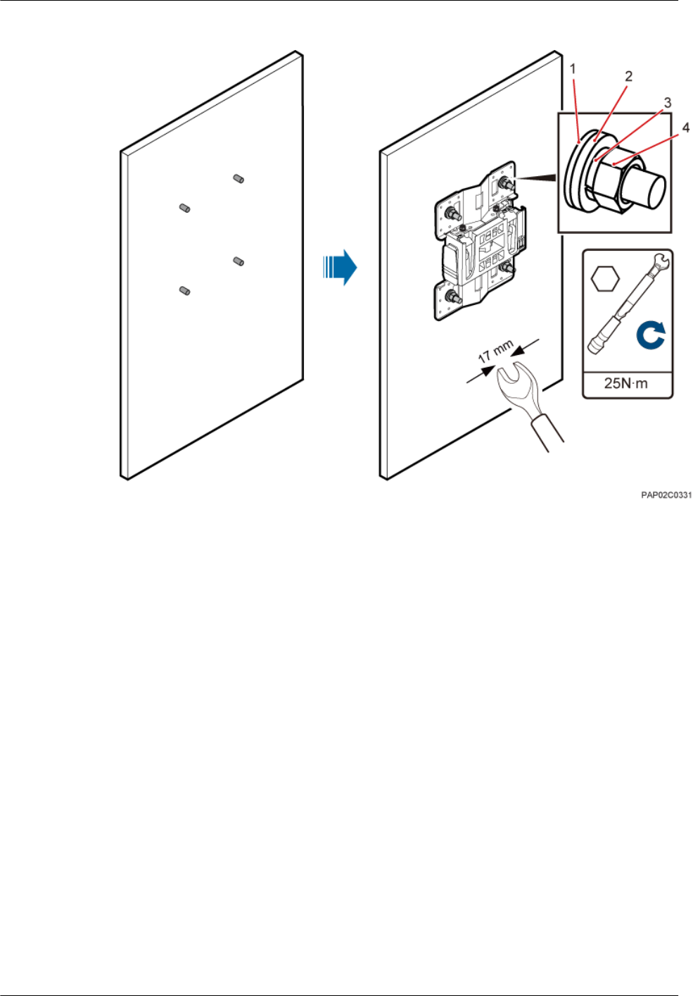
Figure 7-11 Fitting the mounting piece onto the expansion bolts
(1) Insulation
washer
(2) Flat washer (3) Spring washer (4) Nut
Step 5 Install the BTS3902E onto the main mounting bracket until the BTS3902E snaps shut, as shown
in Figure 7-12.
BTS3902E WCDMA
Installation Guide 7 Installing a BTS3902E (using aluminum mounting kits)
Issue 10 (2014-05-16) Huawei Proprietary and Confidential
Copyright © Huawei Technologies Co., Ltd.
43
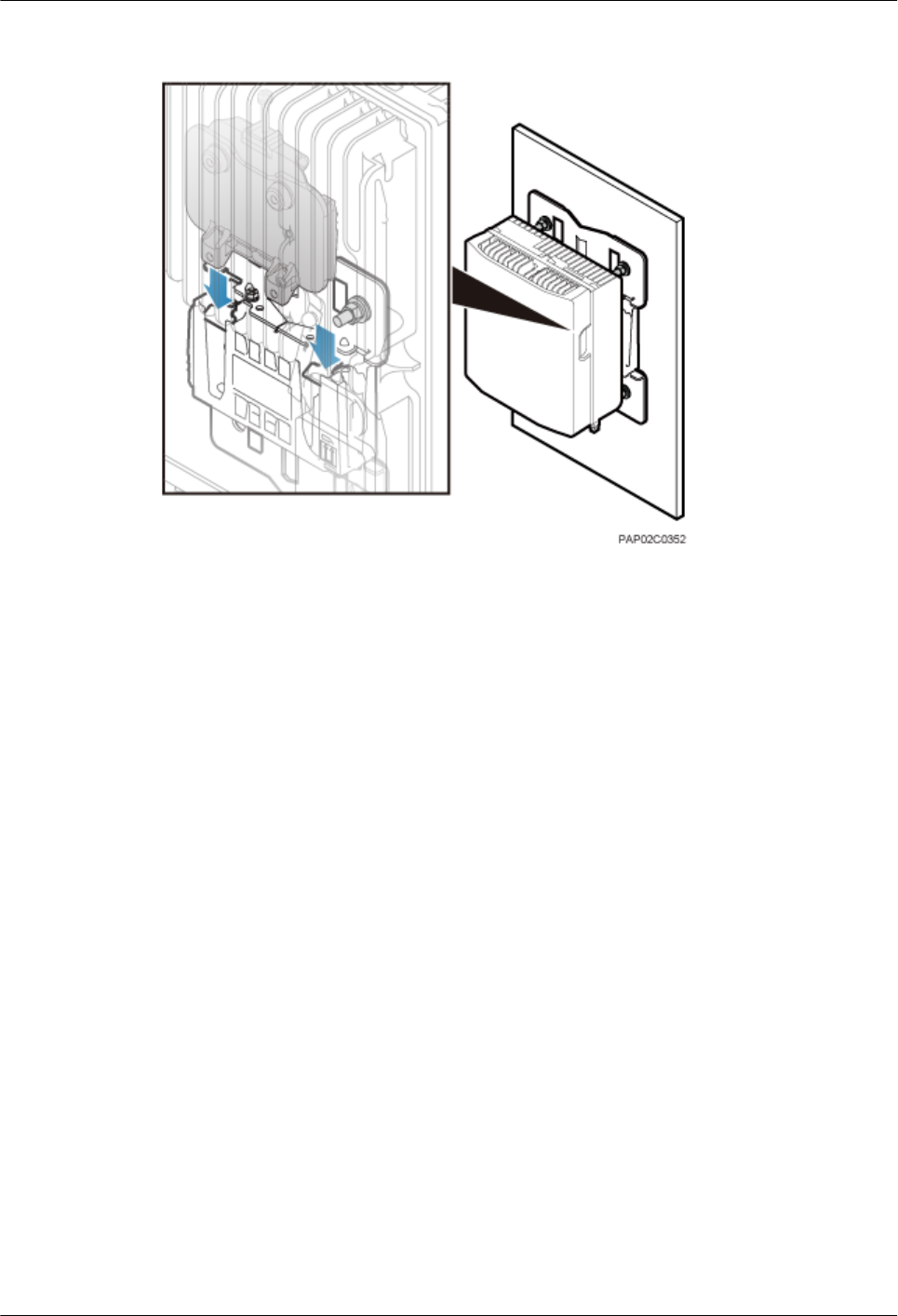
Figure 7-12 Installing the BTS3902E onto the main mounting bracket
----End
7.4 Installing a BTS3902E on a Wood Pole with the Diameter
of 200 mm to 400 mm (7.87 in. to 15.75 in.)
This section describes the procedure and precautions for installing a BTS3902E on a wood pole.
Procedure
Step 1 Drill two holes with the diameter of 18 mm (0.71 in.) on the middle axis of the wood pole,
ensuring that the inter-hole spacing is 203 mm (7.99 in.), as shown in Figure 7-13.
BTS3902E WCDMA
Installation Guide 7 Installing a BTS3902E (using aluminum mounting kits)
Issue 10 (2014-05-16) Huawei Proprietary and Confidential
Copyright © Huawei Technologies Co., Ltd.
44
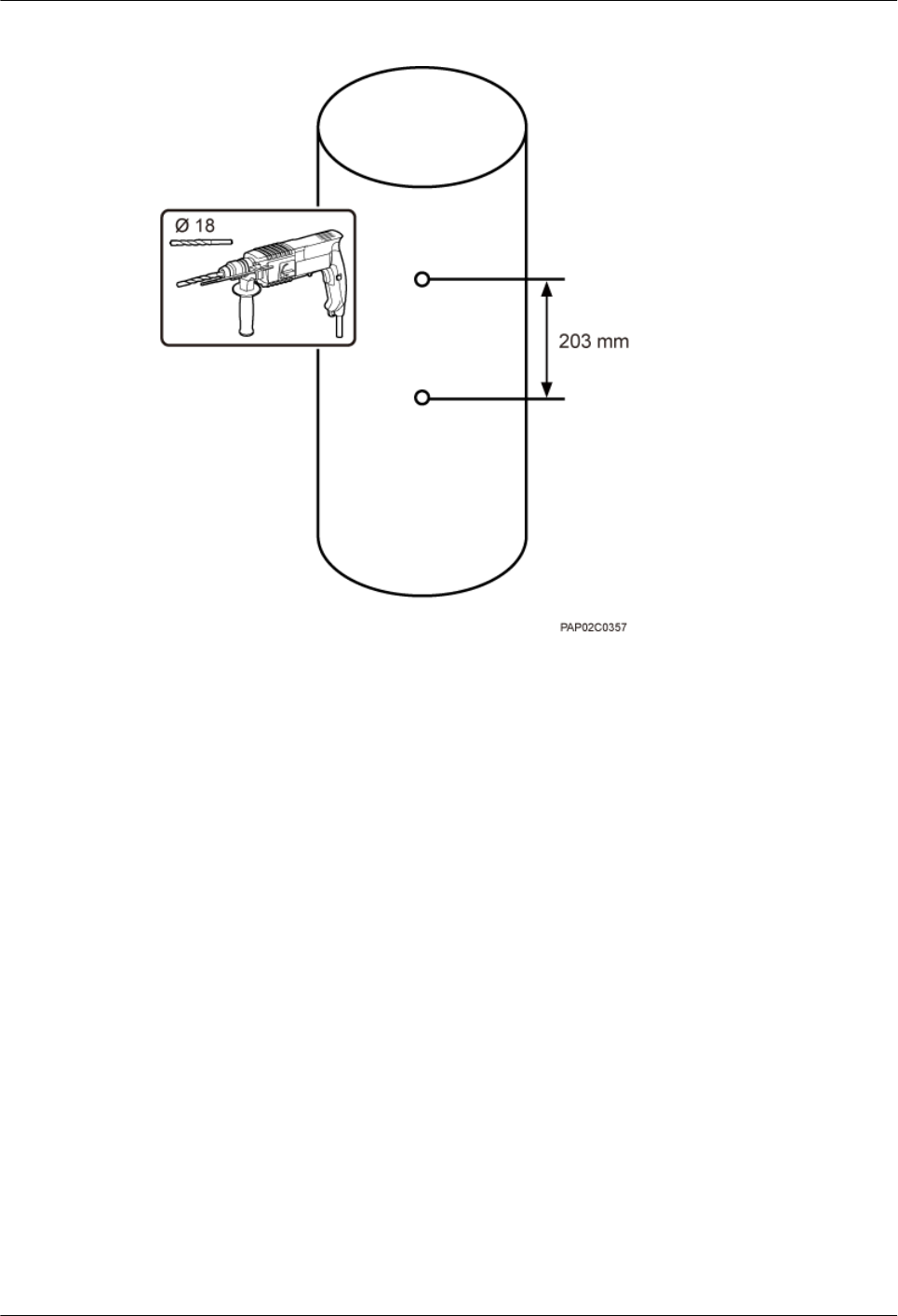
Figure 7-13 Drilling holes
Step 2 Install an adapting plate both on the top and bottom of the main mounting bracket. Tighten two
M6x14 screws to 5 N·m (44.25 lbf·in.) to secure each of the plates, as shown in Figure 7-14.
BTS3902E WCDMA
Installation Guide 7 Installing a BTS3902E (using aluminum mounting kits)
Issue 10 (2014-05-16) Huawei Proprietary and Confidential
Copyright © Huawei Technologies Co., Ltd.
45
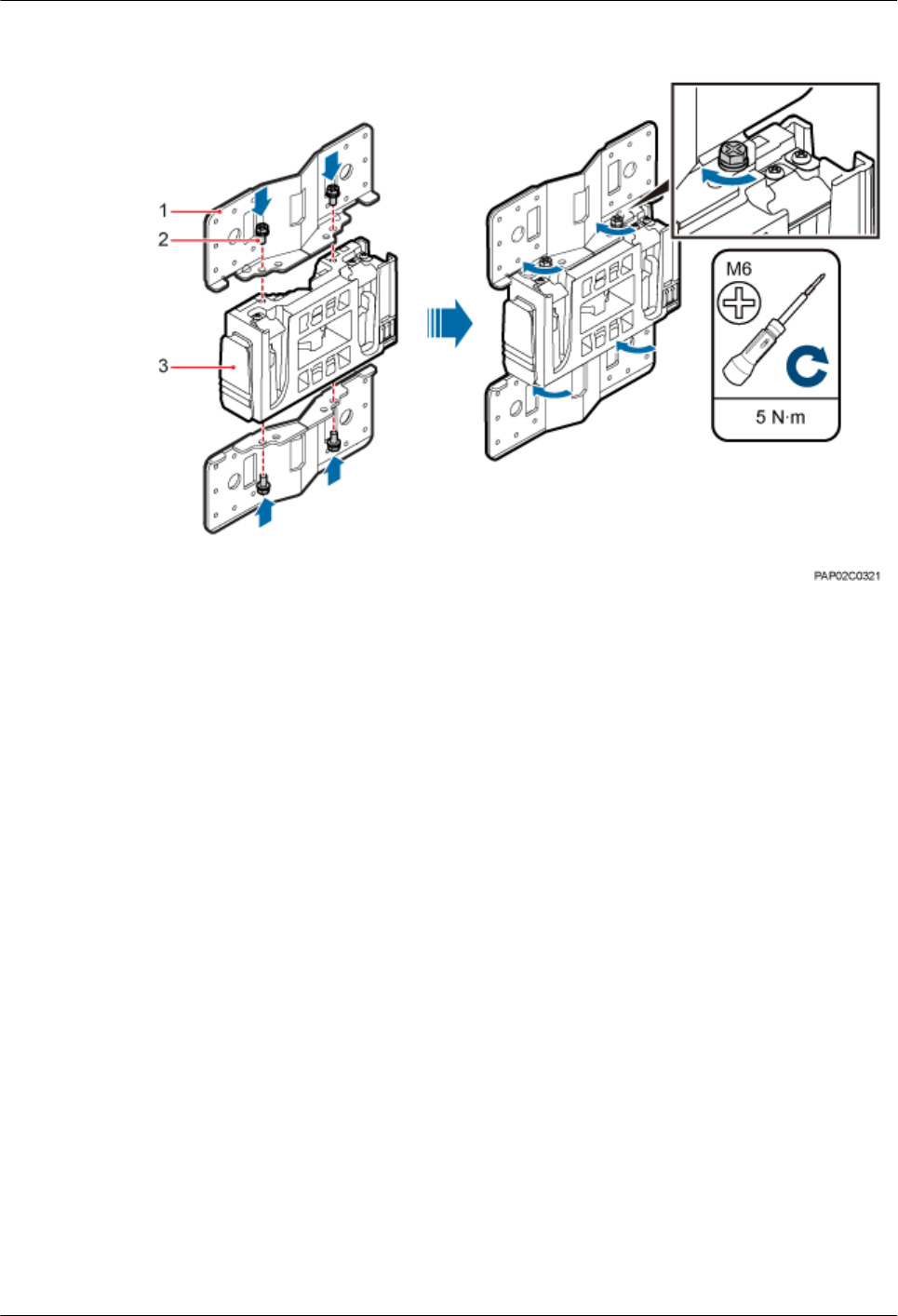
Figure 7-14 Installing the adapting plate assembly
(1) Adapting plate (2) Screw (3) Main mounting bracket
Step 3 Install the securing piece, as shown in Figure 7-15.
1. Align the mounting hole group C with the mounting holes in the wood pole.
2. Lead the two long M16 bolts with spacers through the upper and lower mounting holes.
BTS3902E WCDMA
Installation Guide 7 Installing a BTS3902E (using aluminum mounting kits)
Issue 10 (2014-05-16) Huawei Proprietary and Confidential
Copyright © Huawei Technologies Co., Ltd.
46
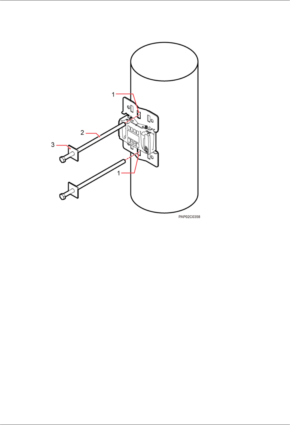
Figure 7-15 Securing the securing pieces
(1) Mounting hole group C (2) Bolt (3) Spacer
Step 4 Tighten the nuts to 80 N·m (708.06 lbf·in.), as shown in Figure 7-16.
BTS3902E WCDMA
Installation Guide 7 Installing a BTS3902E (using aluminum mounting kits)
Issue 10 (2014-05-16) Huawei Proprietary and Confidential
Copyright © Huawei Technologies Co., Ltd.
47
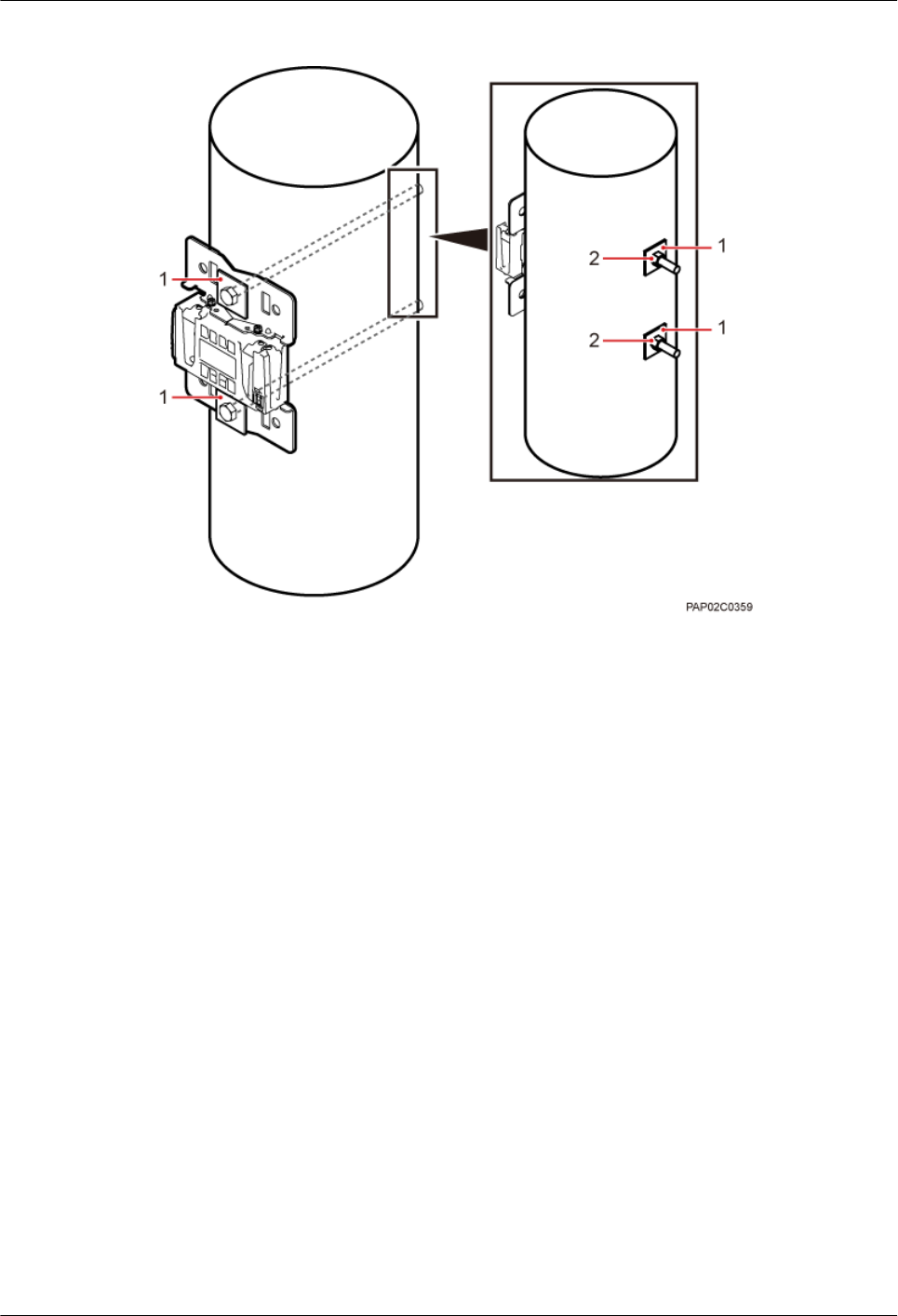
Figure 7-16 Tightening nuts
(1) Spacer (2) Nut
Step 5 Install the BTS3902E on the main mounting bracket until the BTS3902E snaps shut, as shown
in Figure 7-17.
BTS3902E WCDMA
Installation Guide 7 Installing a BTS3902E (using aluminum mounting kits)
Issue 10 (2014-05-16) Huawei Proprietary and Confidential
Copyright © Huawei Technologies Co., Ltd.
48
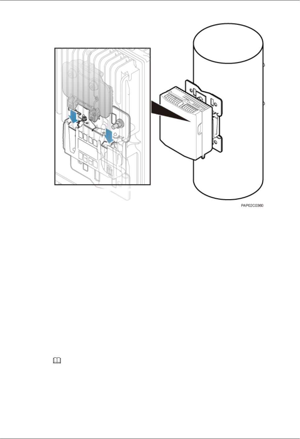
Figure 7-17 Installing the BTS3902E on the main mounting bracket
----End
7.5 Installing BTS3902Es on an IFS06
This section describes the procedure and precautions for installing BTS3902Es on an IFS06.
7.5.1 Assembling the IFS06
This section describes the procedure for assembling an IFS06.
Procedure
Step 1 Use four M12×30 bolt assemblies to secure rear feet to the main frame, with a torque of 50 N·m
(442.54 lbf·in.), as shown in Figure 7-18.
NOTE
Place a foam pad or cardboard under the IFS06 to prevent any damage to the paint.
BTS3902E WCDMA
Installation Guide 7 Installing a BTS3902E (using aluminum mounting kits)
Issue 10 (2014-05-16) Huawei Proprietary and Confidential
Copyright © Huawei Technologies Co., Ltd.
49
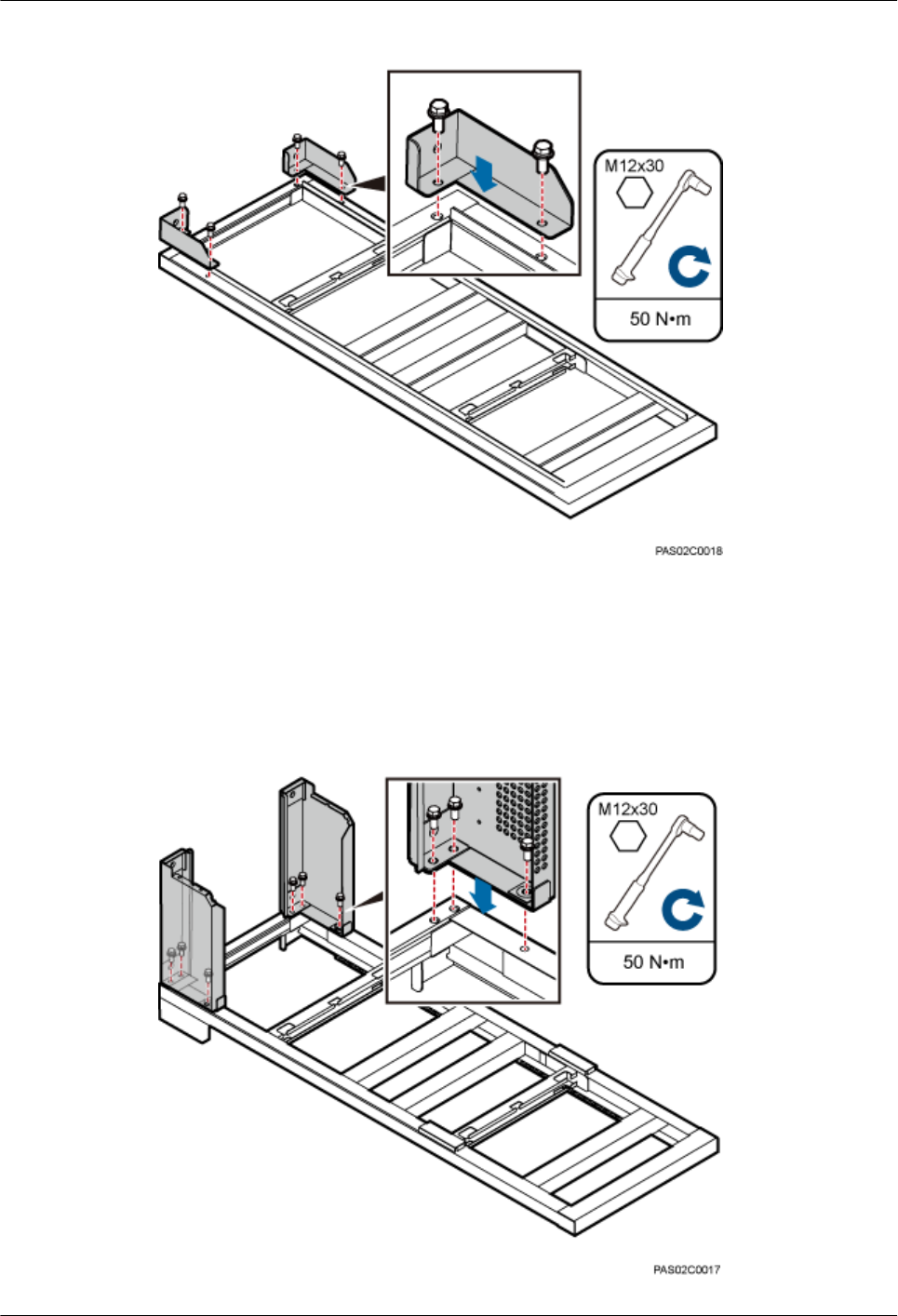
Figure 7-18 Installing the rear feet
Step 2 Turn over the IFS06 and use six M12×30 bolt assemblies to secure front feet to the main frame,
with a torque of 50 N·m (442.54 lbf·in.), as shown in Figure 7-19.
Figure 7-19 Installing the front feet
BTS3902E WCDMA
Installation Guide 7 Installing a BTS3902E (using aluminum mounting kits)
Issue 10 (2014-05-16) Huawei Proprietary and Confidential
Copyright © Huawei Technologies Co., Ltd.
50
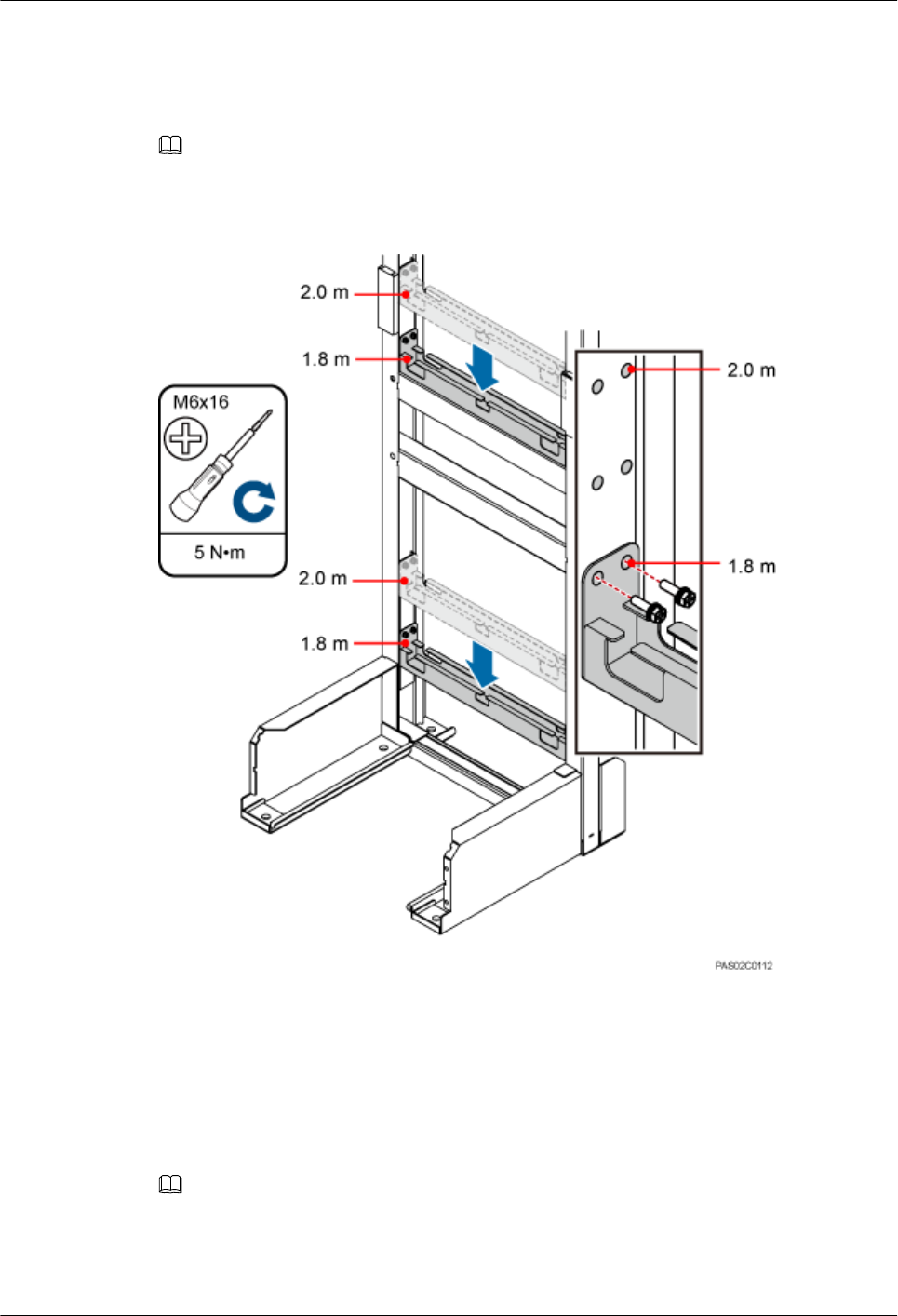
Step 3 In height-restricted scenarios, move the adjustable beams from the positions marked 2 m (6.56
ft) to the positions marked 1.8 m (5.91 ft), as shown in Figure 7-20.
NOTE
The adjustable beams do not need to be moved in height-unrestricted scenarios.
Figure 7-20 Moving the adjustable beam
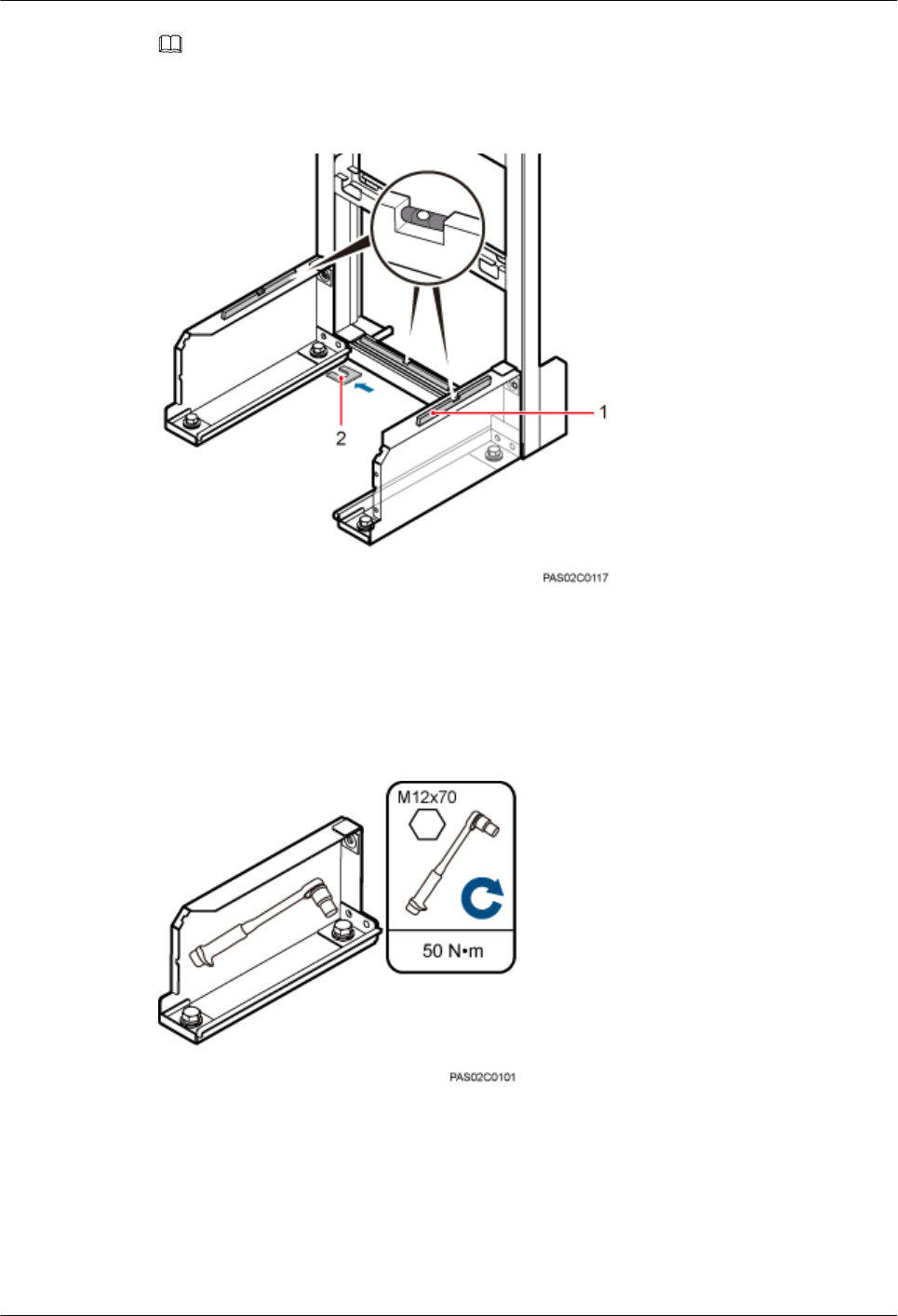
Step 4 Fit the tabs of the cable tray into the corresponding slots on the columns of the IFS06, as shown
in Figure 7-21. Tighten the four M4 screws to 0.6 N·m (5.31 lbf·in.)
Figure 7-21 Installing cable trays
NOTE
In the height-unrestricted scenario, fit the tabs of the cable tray into the slots for the height-unrestricted
scenario. In the height-restricted scenario, fit the tabs of the cable tray into the slots for the height-restricted
scenario.
BTS3902E WCDMA
Installation Guide 7 Installing a BTS3902E (using aluminum mounting kits)
Issue 10 (2014-05-16) Huawei Proprietary and Confidential
Copyright © Huawei Technologies Co., Ltd.
51
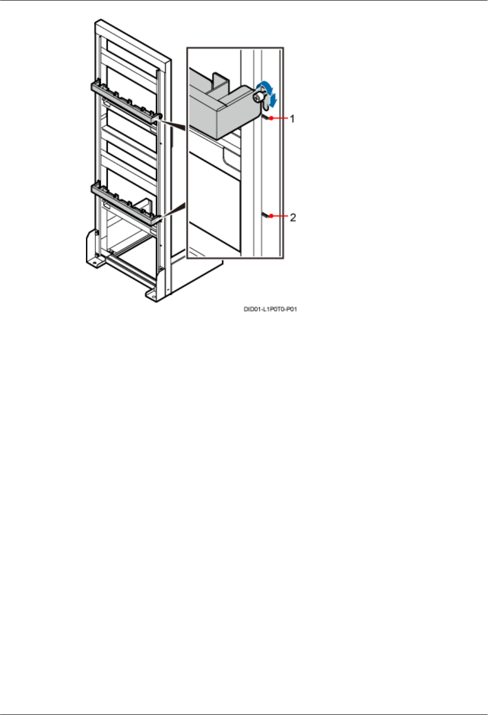
(1) Position for installing the cable tray in the height-
unrestricted scenario
(2) Position for installing the cable tray in the height-
restricted scenario
----End
7.5.2 Installing the IFS06
This section describes the procedures for installing the IFS06 on the concrete floor and ESD
floor.
7.5.2.1 Installing the IFS06 on the Concrete Floor
This section describes the procedure for installing the IFS06 on the concrete floor.
Procedure
Step 1 Place the marking-off template on the floor. Then use a marker to mark four anchor points, as
shown in Figure 7-22.
BTS3902E WCDMA
Installation Guide 7 Installing a BTS3902E (using aluminum mounting kits)
Issue 10 (2014-05-16) Huawei Proprietary and Confidential
Copyright © Huawei Technologies Co., Ltd.
52
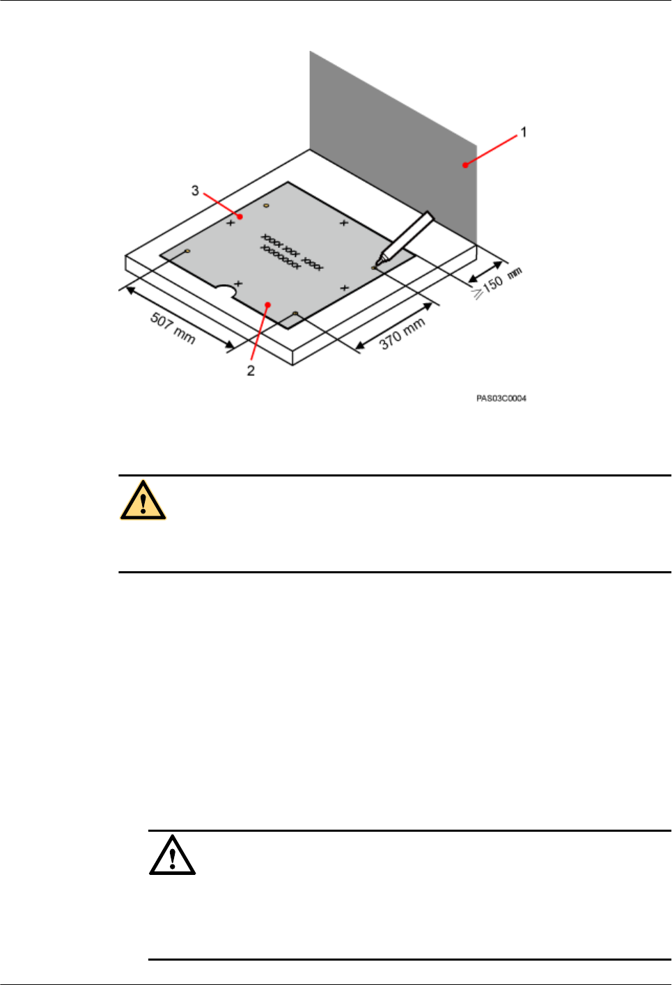
Figure 7-22 Marking anchor points
(1) Wall (2) Front (3) Left
CAUTION
Take proper safety measures to protect your eyes and respiratory tract against the dust before
drilling holes.
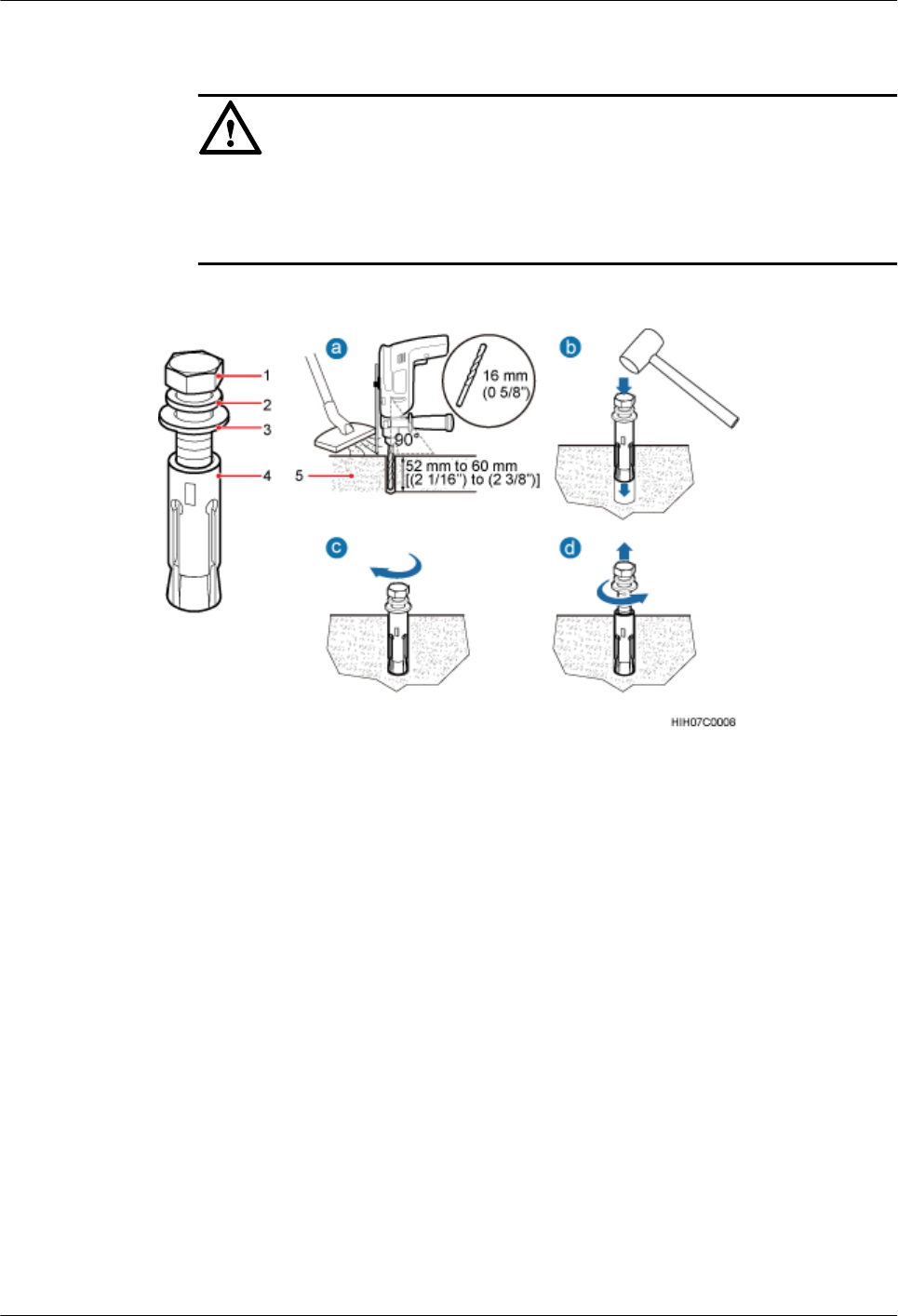
Step 2 Drill holes at the anchor points and install expansion bolts in the holes, as shown in Figure
7-23.
1. Use a hammer drill with a Ф16 drill bit to drill holes with a depth ranging from 52 mm
(2.05 in.) to 60 mm (2.36 in.). Then, use a vacuum cleaner to clear the dust out from inside
and around all the holes, and measure the distances between holes. If any hole does not
meet the requirements, mark new anchor points and drill new holes.
2. Partially tighten an expansion bolt and place it vertically into a hole. Use a rubber mallet
to hit the expansion bolt until the expansion tube completely enters the hole.
3. Tighten the bolts.
4. Remove the bolts, spring washers, and flat washers by turning them counterclockwise.
NOTICE
After dismantling the expansion bolt assembly, ensure that the top of the expansion tube
is level with the concrete pad. Otherwise, the cabinet cannot be installed on the concrete
pad evenly and securely.
BTS3902E WCDMA
Installation Guide 7 Installing a BTS3902E (using aluminum mounting kits)
Issue 10 (2014-05-16) Huawei Proprietary and Confidential
Copyright © Huawei Technologies Co., Ltd.
53
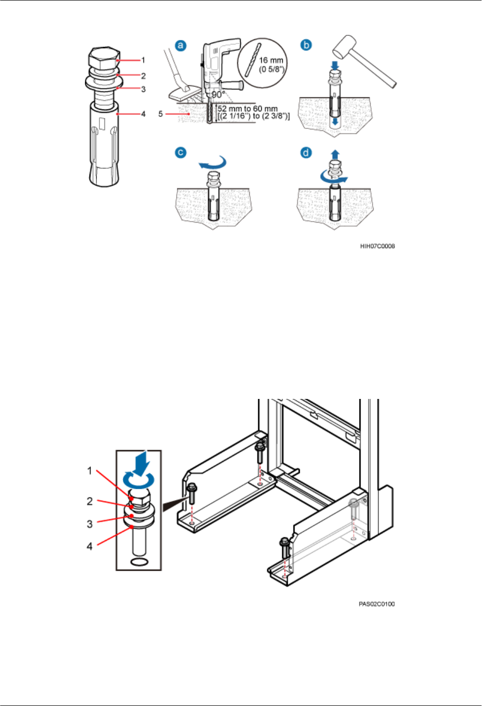
Figure 7-23 Drilling a hole and installing an expansion bolt assembly
(1) M12 expansion bolt (2) Spring washer (3) Flat washer (4) Expansion tube
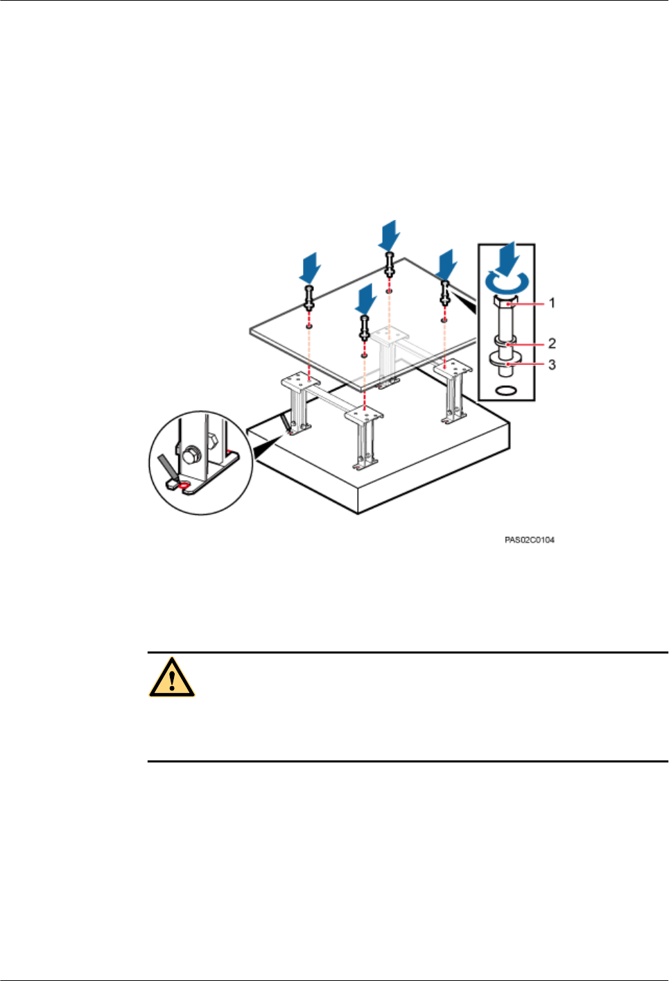
Step 3 Place the IFS06, as shown in Figure 7-24.
1. Place the IFS06, with the mounting holes on the IFS06 aligned with the anchor points on
the floor.
2. Lead each bolt through the spring washer, flat washer, and insulation washer in sequence.
Then install the bolts in the mounting holes on the IFS06.
3. Partially tighten the bolts into the expansion tubes.
Figure 7-24 Installing the bolts
(1) M12x60 bolt (2) Spring washer (3) Flat washer (4) Insulation washer
Step 4 Use a level to measure all sides of the frame and use spacers to level the frame if necessary, as
shown in Figure 7-25.
BTS3902E WCDMA
Installation Guide 7 Installing a BTS3902E (using aluminum mounting kits)
Issue 10 (2014-05-16) Huawei Proprietary and Confidential
Copyright © Huawei Technologies Co., Ltd.
54
NOTE
Spacers must be added at the positions where the expansion bolt assemblies are installed.
Figure 7-25 Checking and leveling the IFS06
(1) Level (2) Spacer
Step 5 Use a socket wrench to tighten the bolts to 50 N·m (442.54 lbf·in.), as shown in Figure 7-26.
Figure 7-26 Tightening the bolts
----End
7.5.2.2 Installing the IFS06 on the ESD Floor
This section describes the procedure for installing the IFS06 on the ESD floor.
BTS3902E WCDMA
Installation Guide 7 Installing a BTS3902E (using aluminum mounting kits)
Issue 10 (2014-05-16) Huawei Proprietary and Confidential
Copyright © Huawei Technologies Co., Ltd.
55
Context
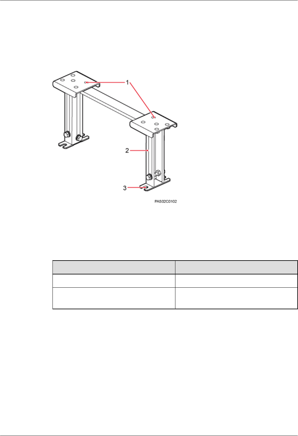
Figure 7-27 shows a support for installing the ESD floor. Such a support can have either an
adjustable height (I) or fixed height (II). The same procedure is used for installing the two types
of supports. This section uses type I as an example.
Figure 7-27 Support for installing the ESD floor
(1) Mounting holes for the ESD floor (2) Support (3) Mounting hole for the concrete floor
The height of an ESD floor is the spacing between the concrete floor and the upper surface of
the ESD floor.
Type Height of the ESD Floor
I296 mm (11.65 in.) to 495 mm (19.49 in.)
II At least 120 mm (4.72 in.), depending on the
actual floor height
Procedure
Step 1 Place the marking-off template on the ESD floor. Then use a marker to mark four anchor points,
as shown in Figure 7-28.
BTS3902E WCDMA
Installation Guide 7 Installing a BTS3902E (using aluminum mounting kits)
Issue 10 (2014-05-16) Huawei Proprietary and Confidential
Copyright © Huawei Technologies Co., Ltd.
56
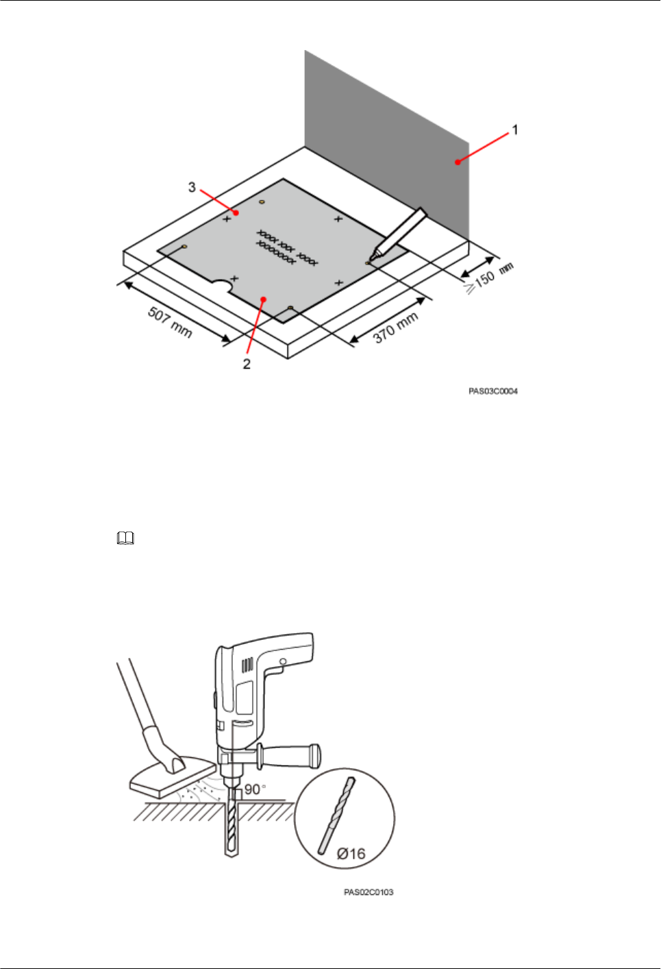
Figure 7-28 Marking anchor points
(1) Wall (2) Front (3) Left
Step 2 Drill holes on the ESD floor, as shown in Figure 7-29. Ensure that the hammer drill penetrates
the ESD floor.
NOTE
Use a vacuum cleaner to clear the dust out from inside and around all the holes, and measure the distances
between holes. If any hole does not meet the requirements, mark new anchor points and drill new holes.
Figure 7-29 Drilling holes
BTS3902E WCDMA
Installation Guide 7 Installing a BTS3902E (using aluminum mounting kits)
Issue 10 (2014-05-16) Huawei Proprietary and Confidential
Copyright © Huawei Technologies Co., Ltd.
57
Step 3 Drill holes on the concrete floor, as shown in Figure 7-30.
1. Place the support under the ESD floor, and use M12x70 bolts to fix the ESD floor to the
support temporarily.
2. According to the support's mounting hole for the concrete floor, use a marker to mark the
positions for installing expansion bolts.
3. Use a measuring tape to measure the inter-hole spacing, and ensure that the center-to-center
separations of the holes are consistent.
Figure 7-30 Marking holes on the concrete floor
(1) M12x70 bolt (2) Spring washer 12 (3) Flat washer 12
CAUTION
Take proper safety measures to protect your eyes and respiratory tract against the dust
before drilling holes.
Step 4 Drill holes at the anchor points on the concrete floor. Then install the expansion bolt assembly,
as shown in Figure 7-31.
1. Use a hammer drill with a Ф16 drill bit to drill holes with a depth ranging from 52 mm
(2.05 in.) to 60 mm (2.36 in.). Then, use a vacuum cleaner to clear the dust out from inside
and around all the holes, and measure the distances between holes. If any hole does not
meet the requirements, mark new anchor points and drill new holes.
2. Partially tighten an expansion bolt and place it vertically into a hole. Use a rubber mallet
to hit the expansion bolt until the expansion tube completely enters the hole.
3. Tighten the bolts.
BTS3902E WCDMA
Installation Guide 7 Installing a BTS3902E (using aluminum mounting kits)
Issue 10 (2014-05-16) Huawei Proprietary and Confidential
Copyright © Huawei Technologies Co., Ltd.
58
4. Remove the bolts, spring washers, and flat washers by turning them counterclockwise.
NOTICE
After dismantling the expansion bolt assembly, ensure that the top of the expansion tube
is level with the concrete pad. Otherwise, the cabinet cannot be installed on the concrete
pad evenly and securely.
Figure 7-31 Drilling a hole and installing an expansion bolt assembly
(1) M12 expansion bolt (2) Spring washer (3) Flat washer (4) Expansion tube
Step 5 Use M12x60 bolts, spring washers, and flat washers to secure the support for installing the ESD
floor on the concrete floor. Tighten the bolts to 50 N·m (442.54 lbf·in.). Figure 7-32 shows how
to secure the support for installing the ESD floor.
BTS3902E WCDMA
Installation Guide 7 Installing a BTS3902E (using aluminum mounting kits)
Issue 10 (2014-05-16) Huawei Proprietary and Confidential
Copyright © Huawei Technologies Co., Ltd.
59
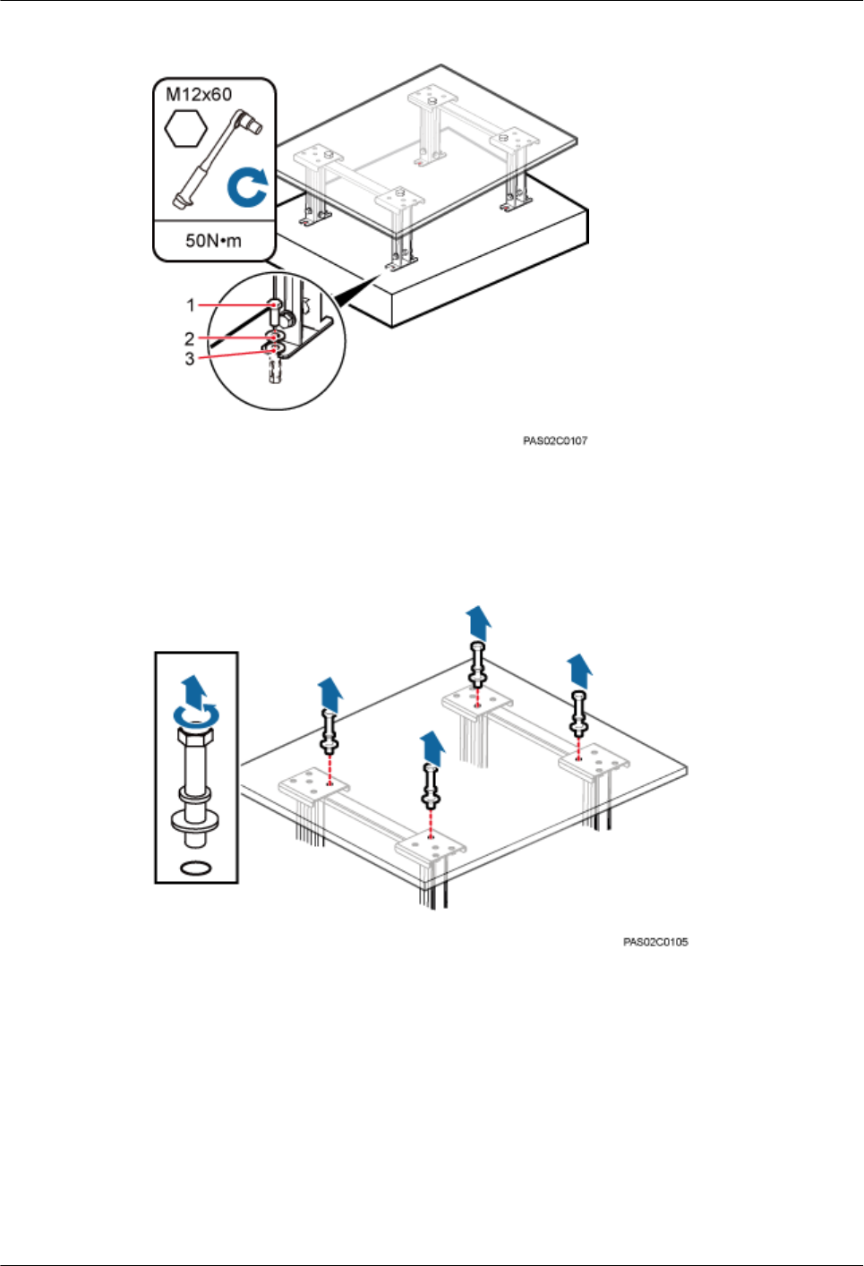
Figure 7-32 Installing supports
Step 6 Remove the bolts that are used to temporarily secure the support, as shown in Figure 7-33.
Figure 7-33 Removing bolts
Step 7 Install the IFS06 to the ESD floor, without tightening the bolts, as shown in Figure 7-34.
BTS3902E WCDMA
Installation Guide 7 Installing a BTS3902E (using aluminum mounting kits)
Issue 10 (2014-05-16) Huawei Proprietary and Confidential
Copyright © Huawei Technologies Co., Ltd.
60
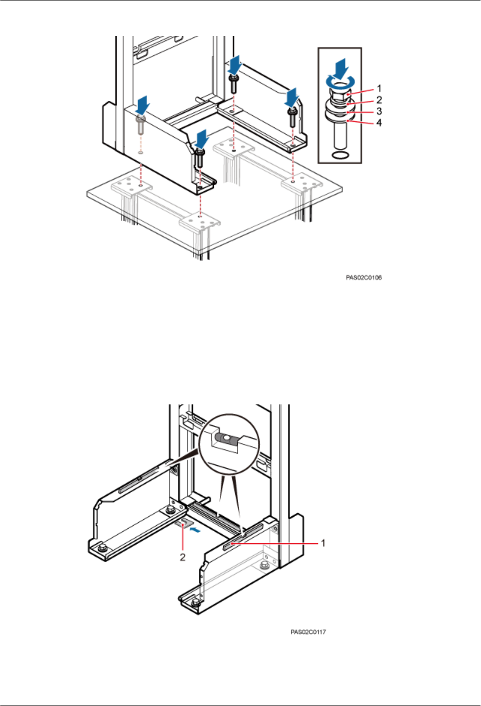
Figure 7-34 Installing the bolts
(1) M12x70 bolt (2) Spring washer (3) Flat washer (4) Insulation washer
Step 8 Use a level to measure all sides of the frame and use spacers to level the frame if necessary, as
shown in Figure 7-35.
Figure 7-35 Checking and leveling the IFS06
(1) Level (2) Spacer
BTS3902E WCDMA
Installation Guide 7 Installing a BTS3902E (using aluminum mounting kits)
Issue 10 (2014-05-16) Huawei Proprietary and Confidential
Copyright © Huawei Technologies Co., Ltd.
61
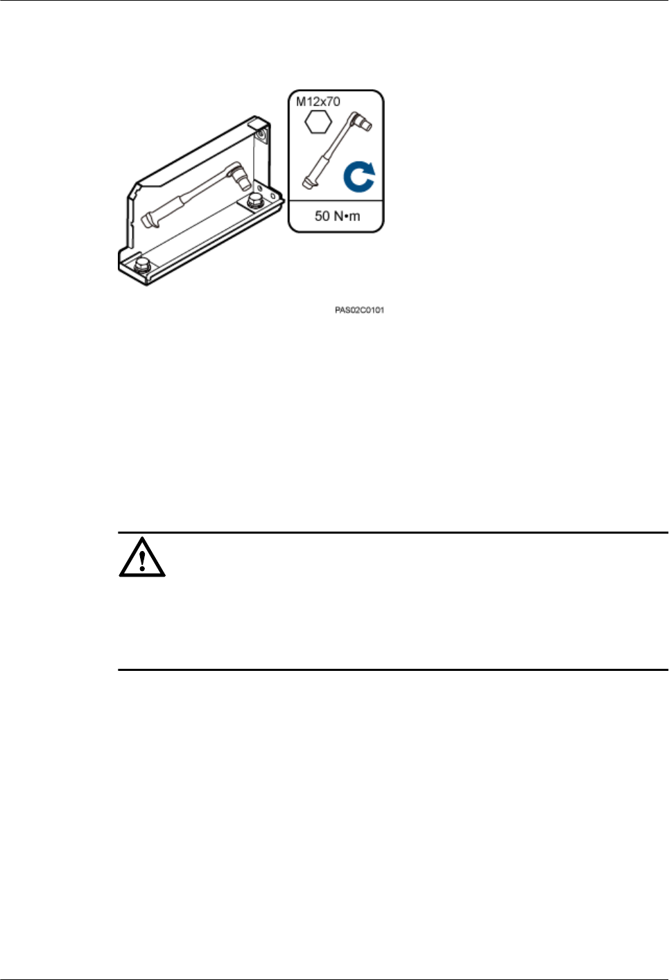
Step 9 Use a socket wrench to tighten the bolts to 50 N·m (442.54 lbf·in.), as shown in Figure 7-36.
Figure 7-36 Tightening the bolts
----End
7.5.3 Installing a Main Bracket
This section describes the procedure for installing a main bracket.
Context
NOTICE
lInstall BTS3902Es in the sequence from bottom to top and from left to right.
lThe contact pieces on the main bracket are locked before a main bracket is mounted.
lRubber washers are easily pressed or broken.
Procedure
lHeight-unrestricted scenario
In the height-unrestricted scenario, main brackets are installed on beam 1 and beam 3, as
shown in Figure 7-37. For details about how to install a main bracket, see the label on an
IFS06.
BTS3902E WCDMA
Installation Guide 7 Installing a BTS3902E (using aluminum mounting kits)
Issue 10 (2014-05-16) Huawei Proprietary and Confidential
Copyright © Huawei Technologies Co., Ltd.
62
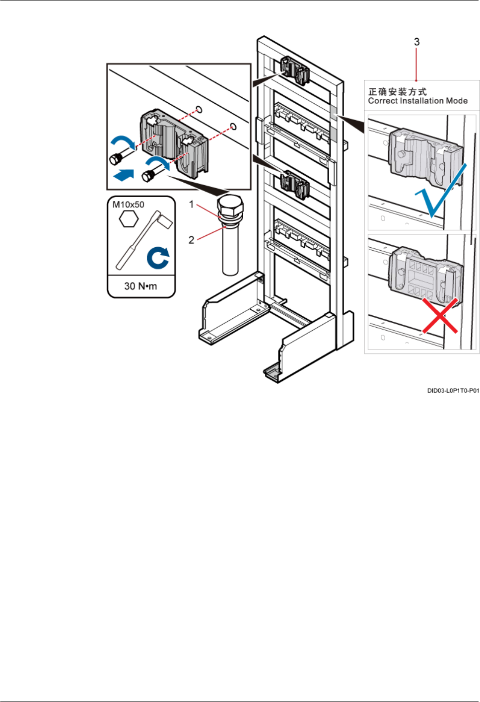
Figure 7-37 Installing main brackets in the height-unrestricted scenario
BTS3902E WCDMA
Installation Guide 7 Installing a BTS3902E (using aluminum mounting kits)
Issue 10 (2014-05-16) Huawei Proprietary and Confidential
Copyright © Huawei Technologies Co., Ltd.
63
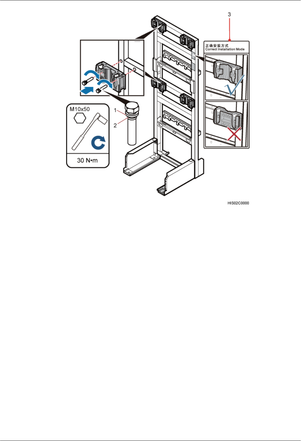
(1) Spring washer (2) Rubber washer (3) Label
lHeight-restricted scenario
In the height-restricted scenario, main brackets are installed on beam 2 and beam 4, as
shown in Figure 7-38. For details about how to install a main bracket, see the label on an
IFS06.
BTS3902E WCDMA
Installation Guide 7 Installing a BTS3902E (using aluminum mounting kits)
Issue 10 (2014-05-16) Huawei Proprietary and Confidential
Copyright © Huawei Technologies Co., Ltd.
64
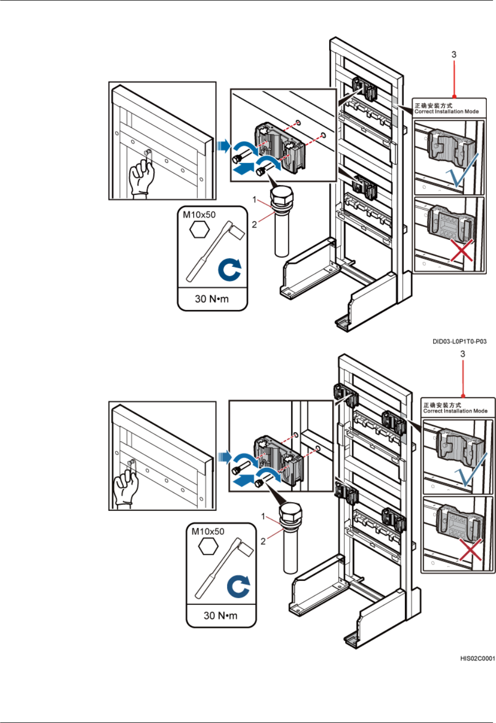
Figure 7-38 Installing main brackets in the height-restricted scenario
(1) Spring washer (2) Rubber washer (3) Label
BTS3902E WCDMA
Installation Guide 7 Installing a BTS3902E (using aluminum mounting kits)
Issue 10 (2014-05-16) Huawei Proprietary and Confidential
Copyright © Huawei Technologies Co., Ltd.
65
----End
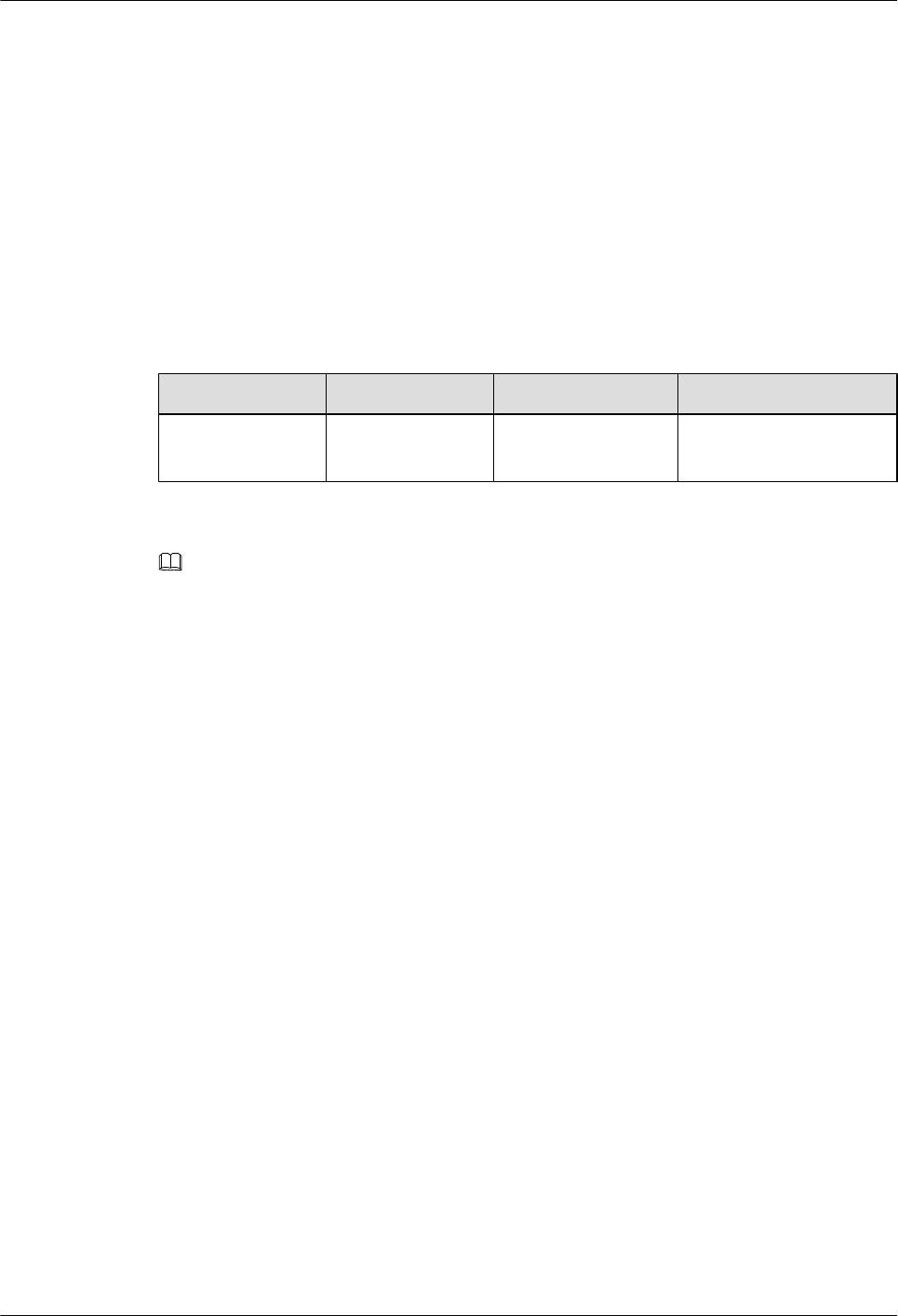
7.5.4 Installing an IFS06 PGND Cable
A PGND cable connects a ground screw on an IFS06 to the onsite ground bar to ensure proper
grounding of the IFS06.
Context
Table 7-1 lists the specifications of a PGND cable.
Table 7-1 Specifications of a PGND cable
Cable One End The Other End Remarks
PGND cable OT terminal (M8) OT terminal (M8) Green and yellow cable
(16 mm2)
NOTE
The cable route depends on actual requirements.
Procedure
Step 1 Connect one end of the PGND cable to the ground terminal of the ground bar on the IFS06 and
the other end to an external ground bar, as shown in Figure 7-39.
BTS3902E WCDMA
Installation Guide 7 Installing a BTS3902E (using aluminum mounting kits)
Issue 10 (2014-05-16) Huawei Proprietary and Confidential
Copyright © Huawei Technologies Co., Ltd.
66
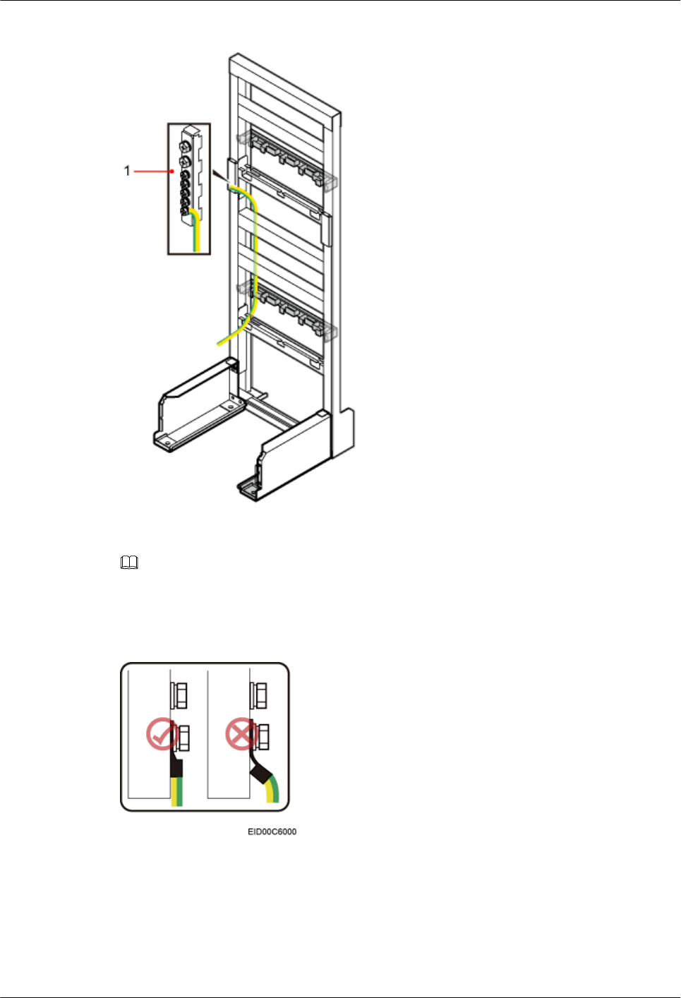
Figure 7-39 Installing a PGND cable
(1) Ground bar
NOTE
When installing the PGND cable, tightly press the OT terminal in the correct direction, as shown in Figure
7-40.
Figure 7-40 Installing an OT terminal in the correct manner
Step 2 Route the cable by referring to 10.1 Cabling Requirements, and then use cable ties to bind the
cable.
BTS3902E WCDMA
Installation Guide 7 Installing a BTS3902E (using aluminum mounting kits)
Issue 10 (2014-05-16) Huawei Proprietary and Confidential
Copyright © Huawei Technologies Co., Ltd.
67
Step 3 Label the cable by referring to Attaching a Cable-Tying Label in Installation Reference.
----End
7.5.5 Installing BTS3902Es
This section describes the procedures for installing BTS3902Es.
Context
NOTE
lPlace a foam pad or cardboard under a BTS3902E to protect the housing from any damage.
lDo not stand a BTS3902E on a floor because the load-bearing capacity of a BTS3902E at the bottom is low.
Procedure
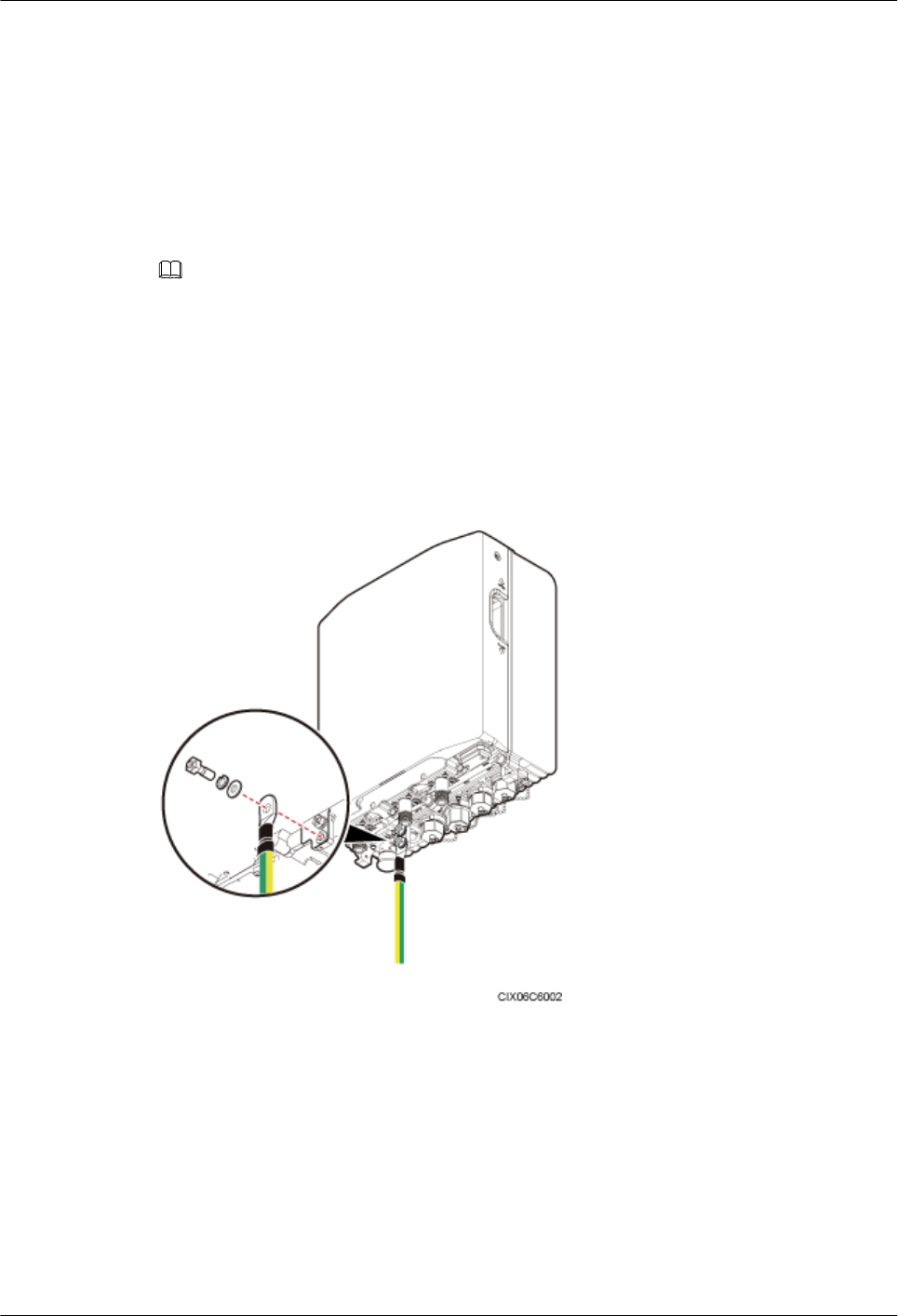
Step 1 Link the M6 OT terminal at one end of the BTS3902E PGND cable to the ground terminal for
the BTS3902E, and leave the other end idle, as shown in Figure 7-41.
Figure 7-41 Connecting the BTS3902E PGND cable to the ground terminal
Step 2 Install the BTS3902E on the main bracket, as shown in Figure 7-42.
BTS3902E WCDMA
Installation Guide 7 Installing a BTS3902E (using aluminum mounting kits)
Issue 10 (2014-05-16) Huawei Proprietary and Confidential
Copyright © Huawei Technologies Co., Ltd.
68
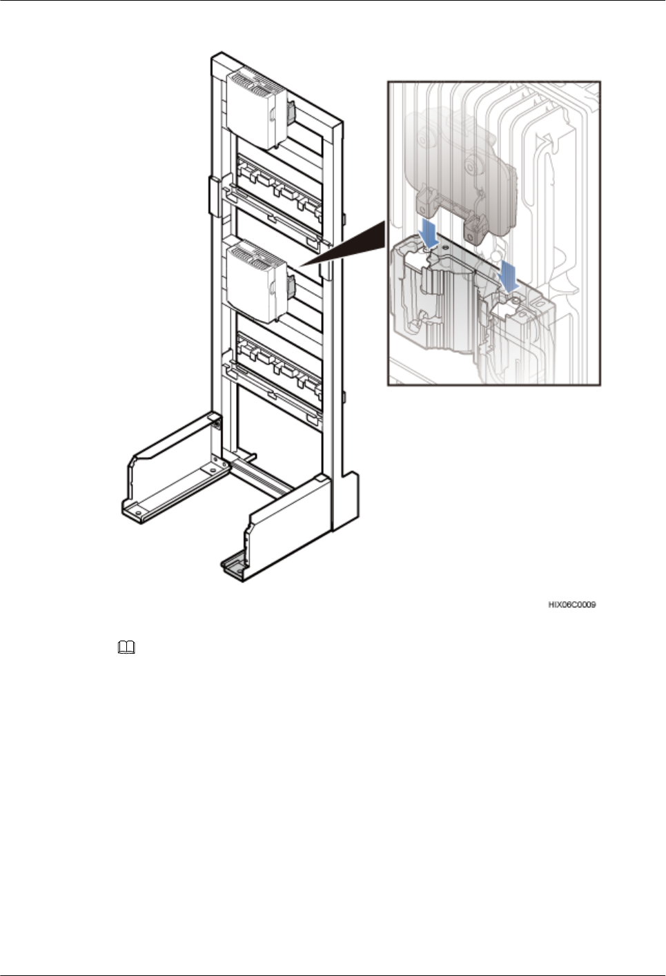
Figure 7-42 Installing the BTS3902E on the main bracket
NOTE
Install lower-level BTS3902Es before installing upper-level BTS3902Es.
----End
BTS3902E WCDMA
Installation Guide 7 Installing a BTS3902E (using aluminum mounting kits)
Issue 10 (2014-05-16) Huawei Proprietary and Confidential
Copyright © Huawei Technologies Co., Ltd.
69

8 Installing a BTS3902E (using angle-
adjustable mounting kits)
About This Chapter
This chapter describes the procedure for installing a BTS3902E with an embedded antenna,
when an angle-adjustable mounting kit is used. The BTS3902E can be installed on a metal pole,
wall, wood pole in different scenarios.
8.1 Installing a BTS3902E on a Pole with the Diameter of 60 mm to 114 mm (2.36 in. to 4.49
in.)
This section describes the procedure and precautions for installing a BTS3902E on a pole with
the diameter of 60 mm to 114 mm (2.36 in. to 4.49 in.).
8.2 Installing a BTS3902E on a Pole with the Diameter of 114 mm to 400 mm (4.49 in. to 15.75
in.)
This section describes the procedure and precautions for installing a BTS3902E on a pole with
the diameter of 114 mm to 400 mm (4.49 in. to 15.75 in.).
8.3 Installing a BTS3902E on a Wall
This section describes the procedure and precautions for installing a BTS3902E on a wall.
8.4 Installing a BTS3902E on a Wood Pole with the Diameter of 200 mm to 400 mm (7.87 in.
to 15.75 in.)
This section describes the procedure and precautions for installing a BTS3902E on a wood pole.
BTS3902E WCDMA
Installation Guide
8 Installing a BTS3902E (using angle-adjustable mounting
kits)
Issue 10 (2014-05-16) Huawei Proprietary and Confidential
Copyright © Huawei Technologies Co., Ltd.
70
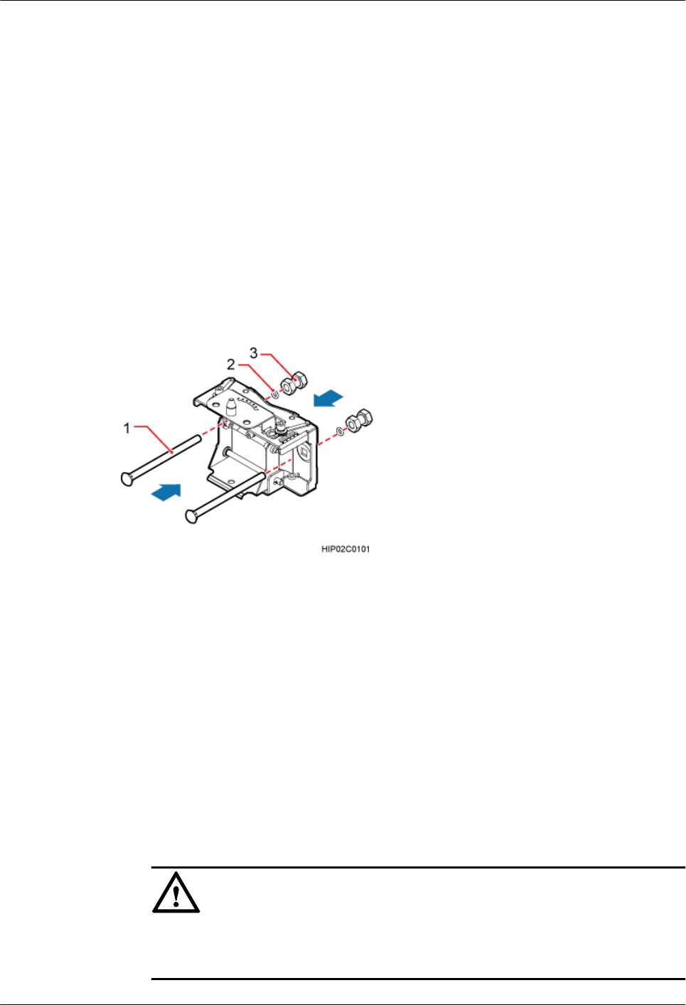
8.1 Installing a BTS3902E on a Pole with the Diameter of 60
mm to 114 mm (2.36 in. to 4.49 in.)
This section describes the procedure and precautions for installing a BTS3902E on a pole with
the diameter of 60 mm to 114 mm (2.36 in. to 4.49 in.).
Procedure
Step 1 Determine the position for installing the main mounting bracket.
Step 2 Put the M10x150 long bolts through the main mounting bracket, add the rubber washers and
double-headed nuts to the bolts in sequence, as shown in Figure 8-1.
Figure 8-1 Installing the main mounting bracket
(1) Long bolt (2) Rubber washer (3) Double-headed nut
Step 3 Install the main mounting bracket and auxiliary mounting bracket, as shown in Figure 8-2.
1. Add the double-headed nuts to the long bolts. Rotate a double-headed nut onto each of the
bolts until the double-headed nuts are about 50 mm (1.97 in.) away from the edges of the
bolts.
2. Ensure that the arrow on the auxiliary bracket points up. Then fit the U-shaped slot of the
auxiliary bracket vertically onto the double-headed nut on the main mounting bracket and
ensure that the hoist clamp has reset automatically.
3. Use a torque wrench to tighten the double-headed nuts to 40 N·m (354.03 lbf·in.) so that
the main and auxiliary mounting brackets are secured onto the pole.
NOTICE
Tighten the two double-headed nuts synchronously and so that the distances between the
two sides of the main and auxiliary brackets are the same.
BTS3902E WCDMA
Installation Guide
8 Installing a BTS3902E (using angle-adjustable mounting
kits)
Issue 10 (2014-05-16) Huawei Proprietary and Confidential
Copyright © Huawei Technologies Co., Ltd.
71
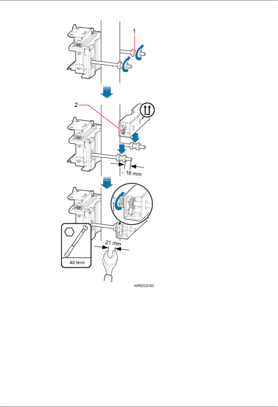
Figure 8-2 Installing the main and auxiliary mounting brackets
(1) Double-headed nut (2) Hoist clamp
Step 4 Install the BTS3902E onto the main mounting bracket vertically. Put the upper positioning pin
through the hole on the attachment plate and the lower positioning pin through the hole on the
main mounting bracket, as shown in Figure 8-3.
BTS3902E WCDMA
Installation Guide
8 Installing a BTS3902E (using angle-adjustable mounting
kits)
Issue 10 (2014-05-16) Huawei Proprietary and Confidential
Copyright © Huawei Technologies Co., Ltd.
72
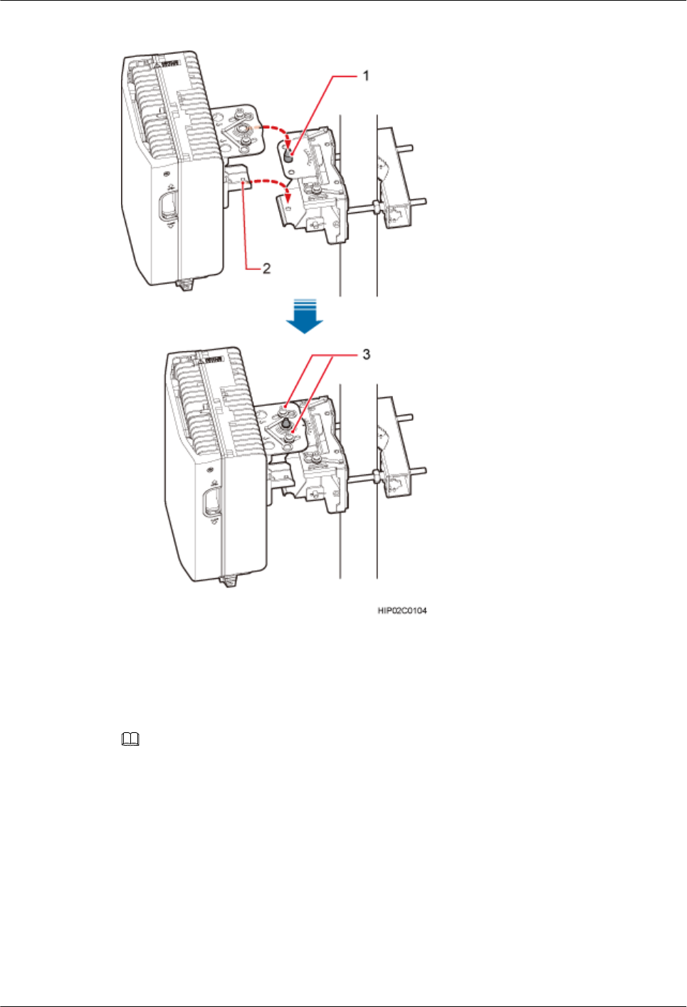
Figure 8-3 Installing the BTS3902E onto the main mounting bracket
(1) Upper positioning pin (2) Lower positioning pin (3) Positioning screw
Step 5 Adjust the installation angle of the BTS3902E: horizontal angle ±30°, vertical angle ±10°.
NOTE
lIf the positioning pin is tightened too hard, the installation angle cannot be adjusted. In this case, loosen the
positioning screw first.
lThe horizontal angle and vertical angle can be adjusted simultaneously. The vertical angle can be determined
either from the plan or elevation view.
lAdjust the horizontal angle.
1. Hold the BTS3902E to adjust the horizontal angle to a proper degree.
2. Use an M8 inner hexagon torque screwdriver to tighten the positioning screw to 12 N·m
(106.21 lbf·in.), as shown in Figure 8-4.
BTS3902E WCDMA
Installation Guide
8 Installing a BTS3902E (using angle-adjustable mounting
kits)
Issue 10 (2014-05-16) Huawei Proprietary and Confidential
Copyright © Huawei Technologies Co., Ltd.
73

Figure 8-4 Adjusting the horizontal angle
(1) Positioning screw
lAdjust the vertical angle. Figure 8-5 shows the vertical angle from the plan view. If the
vertical angle is from the elevation view, adjust the angle to the opposite direction.
1. Hold the BTS3902E to adjust the vertical angle from the plan view or elevation view to
proper degrees.
2. Use an M8 inner hexagon torque screwdriver to tighten the positioning screw to 12 N·m
(106.21 lbf·in.).
BTS3902E WCDMA
Installation Guide
8 Installing a BTS3902E (using angle-adjustable mounting
kits)
Issue 10 (2014-05-16) Huawei Proprietary and Confidential
Copyright © Huawei Technologies Co., Ltd.
74

Figure 8-5 Adjusting the vertical angle
(1) Positioning screw
Step 6 Ensure that the positioning screws both in the vertical direction and horizontal direction have
been secured. Tighten the positioning screws in both directions simultaneously.
----End
8.2 Installing a BTS3902E on a Pole with the Diameter of 114
mm to 400 mm (4.49 in. to 15.75 in.)
This section describes the procedure and precautions for installing a BTS3902E on a pole with
the diameter of 114 mm to 400 mm (4.49 in. to 15.75 in.).
BTS3902E WCDMA
Installation Guide
8 Installing a BTS3902E (using angle-adjustable mounting
kits)
Issue 10 (2014-05-16) Huawei Proprietary and Confidential
Copyright © Huawei Technologies Co., Ltd.
75
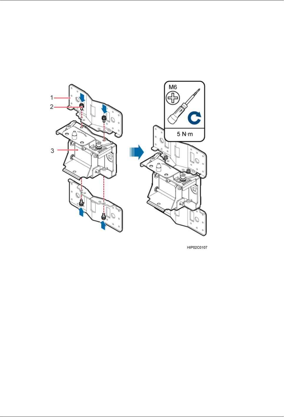
Procedure
Step 1 Remove the double-headed nuts and auxiliary mounting bracket from the main mounting
bracket.
Step 2 Install an adapting plate both on the top and bottom of the main mounting bracket. Tighten two
M6x14 screws to 5 N·m (44.25 lbf·in.) to secure each of the plates, as shown in Figure 8-6.
Figure 8-6 Installing the adapting plate assembly
(1) Adapting plate (2) Screw (3) Main mounting bracket
Step 3 Install two hose clamps through the mounting hole group B on the adapting plates, as shown in
Figure 8-7.
BTS3902E WCDMA
Installation Guide
8 Installing a BTS3902E (using angle-adjustable mounting
kits)
Issue 10 (2014-05-16) Huawei Proprietary and Confidential
Copyright © Huawei Technologies Co., Ltd.
76
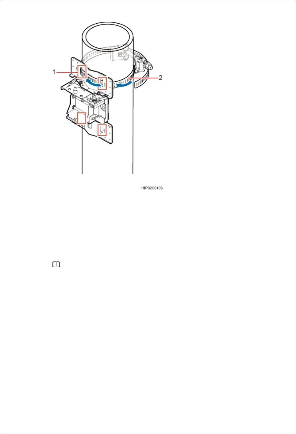
Figure 8-7 Installing the hose clamps through the mounting hole group B
(1) Mounting hole group B (2) Hose clamp
Step 4 Install the mounting piece, as shown in Figure 8-8.
1. Tighten the M12 screws to 30 N·m (265.52 lbf·in.)
2. Use a level to check whether the adapting plate is on a horizontal plane.
NOTE
Secure the upper hose clamp before securing the lower clamp.
BTS3902E WCDMA
Installation Guide
8 Installing a BTS3902E (using angle-adjustable mounting
kits)
Issue 10 (2014-05-16) Huawei Proprietary and Confidential
Copyright © Huawei Technologies Co., Ltd.
77
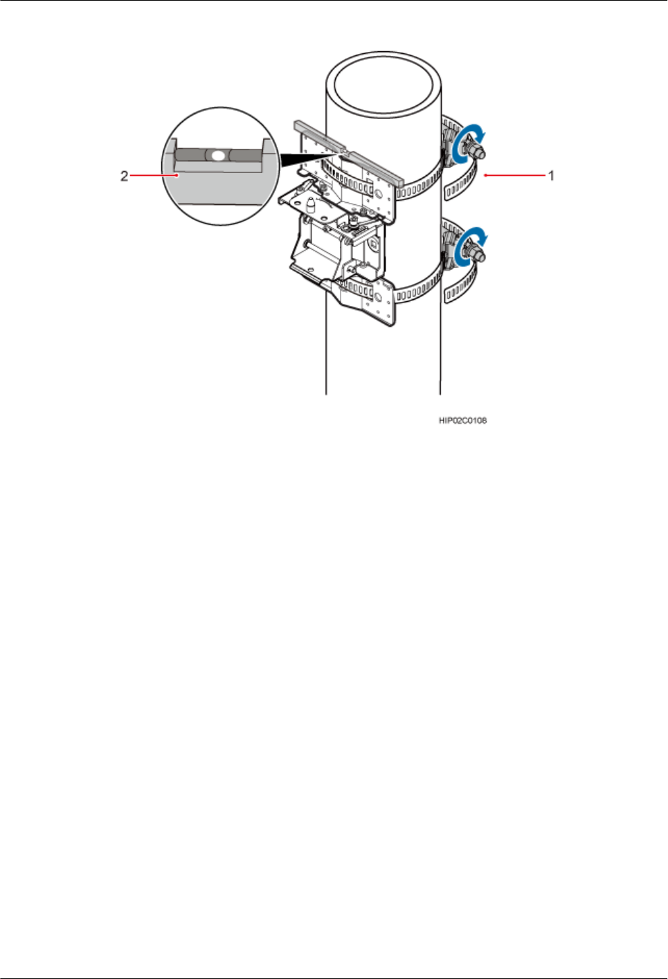
Figure 8-8 Securing the hose clamps
(1) Hose clamp (2) Level
Step 5 Install the BTS3902E onto the main mounting bracket vertically. Put the upper positioning pin
through the hole on the attachment plate and the lower positioning pin through the hole on the
main mounting bracket, pre-tighten the positioning screws, as shown in Figure 8-9.
BTS3902E WCDMA
Installation Guide
8 Installing a BTS3902E (using angle-adjustable mounting
kits)
Issue 10 (2014-05-16) Huawei Proprietary and Confidential
Copyright © Huawei Technologies Co., Ltd.
78
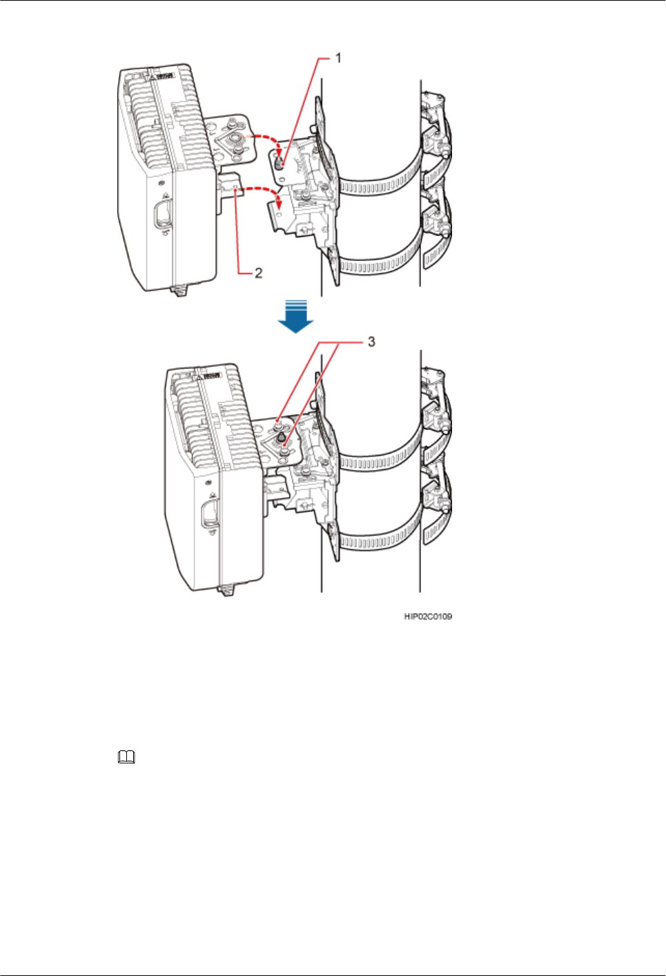
Figure 8-9 Installing the BTS3902E onto the main mounting bracket
(1) Upper positioning pin (2) Lower positioning pin (3) Positioning screw
Step 6 Adjust the installation angle of the BTS3902E: horizontal angle ±30°, vertical angle ±10°.
NOTE
lIf the positioning pin is tightened too hard, the installation angle cannot be adjusted. In this case, loosen the
positioning screw first.
lThe horizontal angle and vertical angle can be adjusted simultaneously. The vertical angle can be determined
either from the plan or elevation view.
lAdjust the horizontal angle.
1. Hold the BTS3902E to adjust the horizontal angle to a proper degree.
2. Use an M8 inner hexagon torque screwdriver to tighten the positioning screw to 12 N·m
(106.21 lbf·in.), as shown in Figure 8-10.
BTS3902E WCDMA
Installation Guide
8 Installing a BTS3902E (using angle-adjustable mounting
kits)
Issue 10 (2014-05-16) Huawei Proprietary and Confidential
Copyright © Huawei Technologies Co., Ltd.
79
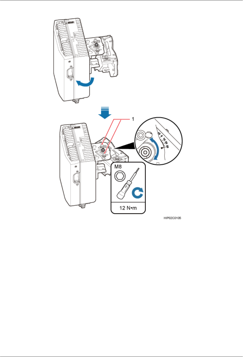
Figure 8-10 Adjusting the horizontal angle
(1) Positioning screw
lAdjust the vertical angle. Figure 8-11 shows the vertical angle from the plan view. If the
vertical angle is from the elevation view, adjust the angle to the opposite direction.
1. Hold the BTS3902E to adjust the vertical angle from the plan view or elevation view to
proper degrees.
2. Use an M8 inner hexagon torque screwdriver to tighten the positioning screw to 12 N·m
(106.21 lbf·in.).
BTS3902E WCDMA
Installation Guide
8 Installing a BTS3902E (using angle-adjustable mounting
kits)
Issue 10 (2014-05-16) Huawei Proprietary and Confidential
Copyright © Huawei Technologies Co., Ltd.
80
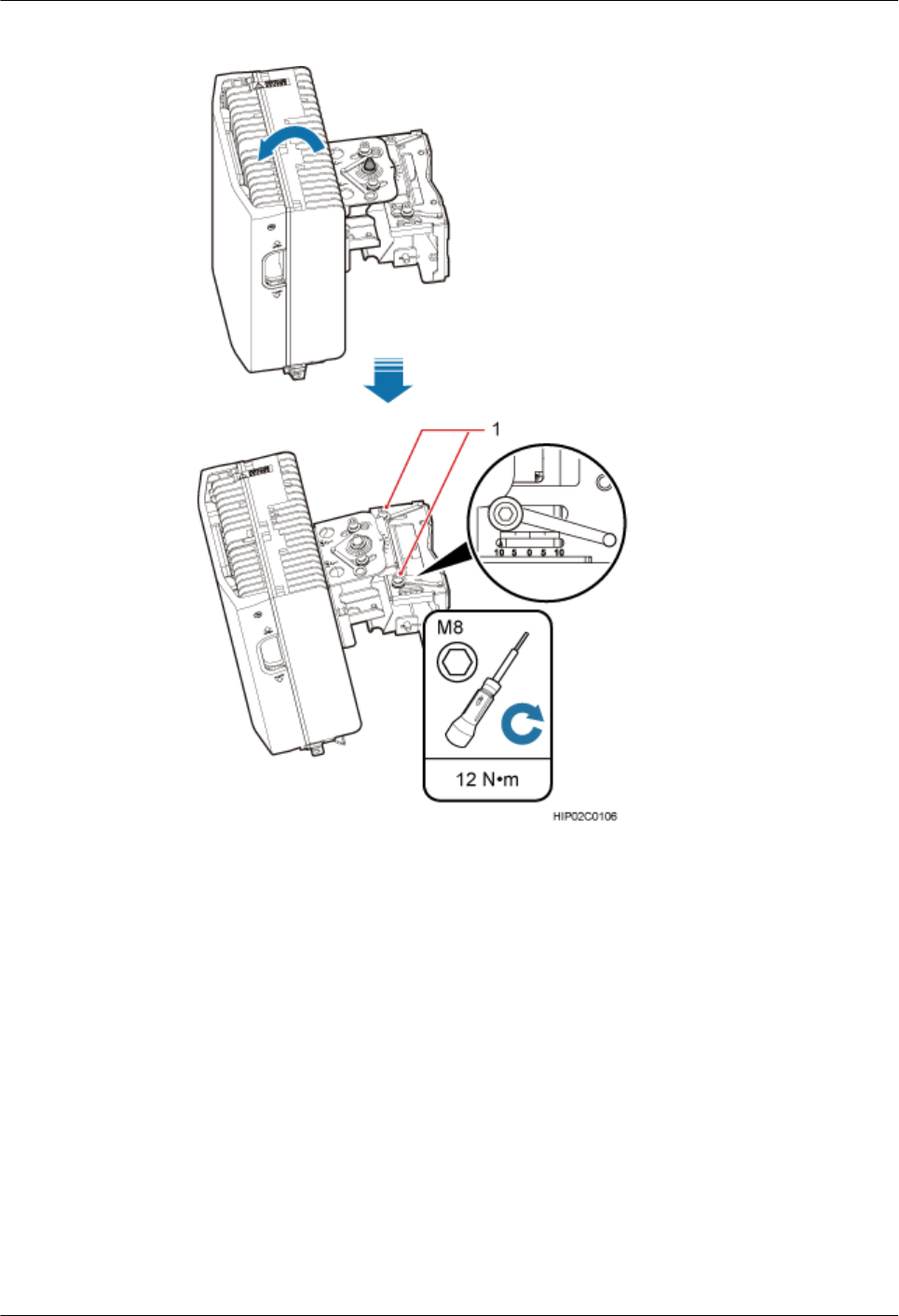
Figure 8-11 Adjusting the vertical angle
(1) Positioning screw
Step 7 Ensure that the positioning screws both in the vertical direction and horizontal direction have
been secured. Tighten the positioning screws in both directions simultaneously.
----End
8.3 Installing a BTS3902E on a Wall
This section describes the procedure and precautions for installing a BTS3902E on a wall.
BTS3902E WCDMA
Installation Guide
8 Installing a BTS3902E (using angle-adjustable mounting
kits)
Issue 10 (2014-05-16) Huawei Proprietary and Confidential
Copyright © Huawei Technologies Co., Ltd.
81
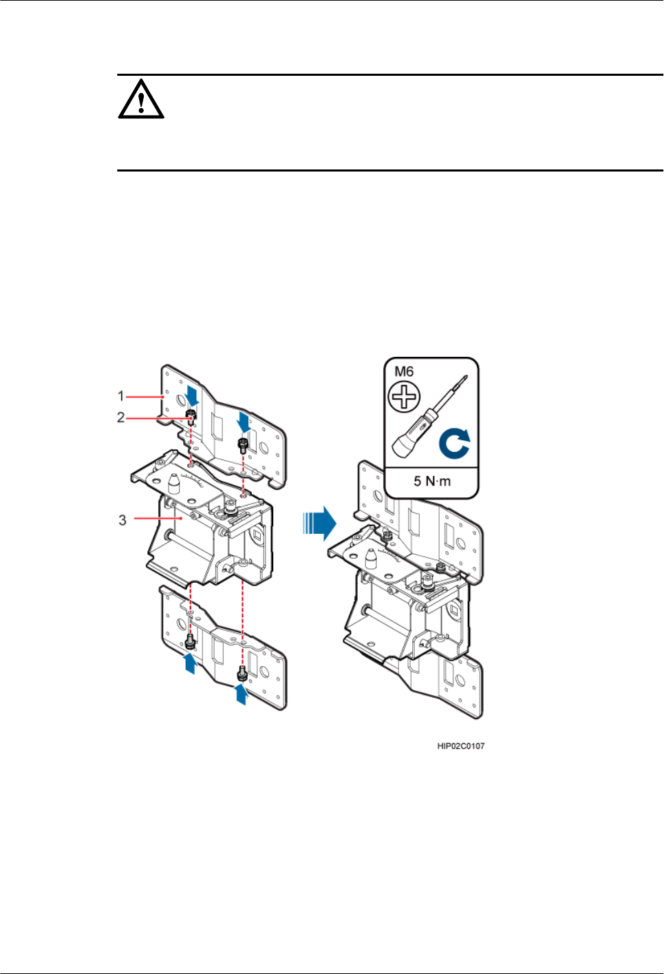
Context
NOTICE
You must use adjustable torque tools to tighten all the screws and nuts to the required torque
described in this document.
Procedure
Step 1 Remove the double-headed nuts and auxiliary mounting bracket from the main mounting
bracket.
Step 2 Install an adapting plate both on the top and bottom of the main mounting bracket. Tighten two
M6x14 screws to 5 N·m (44.25 lbf·in.) to secure each of the plates, as shown in Figure 8-12.
Figure 8-12 Installing the adapting plate assembly
(1) Adapting plate (2) Screw (3) Main mounting bracket
Step 3 Place the adapting plates against the wall, use a level to verify that the plates are horizontal, and
then use a marker to mark anchor points, as shown in Figure 8-13.
BTS3902E WCDMA
Installation Guide
8 Installing a BTS3902E (using angle-adjustable mounting
kits)
Issue 10 (2014-05-16) Huawei Proprietary and Confidential
Copyright © Huawei Technologies Co., Ltd.
82
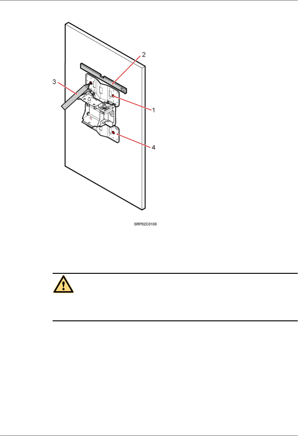
Figure 8-13 Marking anchor points
(1) Mounting hole group A (2) Level (3) Marker (4) Adapting plate
CAUTION
To prevent inhalation or eye contact with dust, take adequate preventive measures when drilling
holes.
Step 4 Drill holes at the anchor points, and then install expansion bolt assemblies, as shown in Figure
8-14.
BTS3902E WCDMA
Installation Guide
8 Installing a BTS3902E (using angle-adjustable mounting
kits)
Issue 10 (2014-05-16) Huawei Proprietary and Confidential
Copyright © Huawei Technologies Co., Ltd.
83
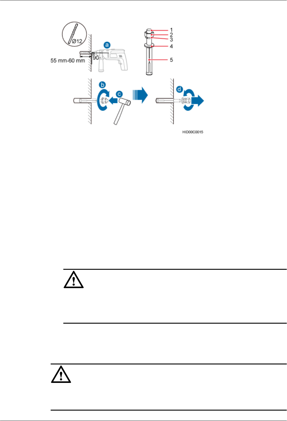
Figure 8-14 Drilling holes and install expansion bolt assemblies
(1) M10x80 bolt (2) Nut (3) Spring washer (4) Flat washer (5) Expansion tube
1. Use a hammer drill with a φ12 bit to drill holes perpendicularly with the wall at the marked
anchor points. Ensure that the depth of each hole ranges from 55 mm to 60 mm (2.17 in.
to 2.36 in.) and each hole is of the same depth.
2. Use a vacuum cleaner to clear dust inside and around the holes, and then measure the inter-
hole spacing. If the spacing is too wide or too narrow, drill holes again.
3. Tighten each expansion bolt slightly and place them perpendicularly into each hole.
4. Hit each expansion bolt using a rubber mallet to enable the expansion tube to enter the hole
completely.
5. Remove the M10x80 bolt, nut, spring washer, and flat washer from each expansion bolt
assembly in sequence.
NOTICE
After dismantling an expansion bolt assembly, ensure that the top of the expansion tube is
on the same level as the wall. Otherwise, the device cannot be installed on the wall evenly
and securely.
Step 5 Fit the mounting piece on the expansion bolt, and then use a combination wrench (with a size
of 17 mm or 0.67 in.) to tighten the expansion bolts to 25 N·m (265.52 lbf·in.), as shown in
Figure 8-15.
NOTICE
Ensure that the arrow on the main mounting bracket points upwards when installing the mounting
piece.
BTS3902E WCDMA
Installation Guide
8 Installing a BTS3902E (using angle-adjustable mounting
kits)
Issue 10 (2014-05-16) Huawei Proprietary and Confidential
Copyright © Huawei Technologies Co., Ltd.
84
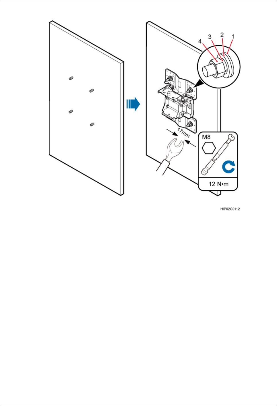
Figure 8-15 Fitting the mounting piece onto the expansion bolts
(1) Insulation
washer
(2) Flat washer (3) Spring washer (4) Nut
Step 6 Install the BTS3902E onto the main mounting bracket vertically. Put the upper positioning pin
through the hole on the attachment plate and the lower positioning pin through the hole on the
main mounting bracket, pre-tighten the positioning screws, as shown in Figure 8-16.
BTS3902E WCDMA
Installation Guide
8 Installing a BTS3902E (using angle-adjustable mounting
kits)
Issue 10 (2014-05-16) Huawei Proprietary and Confidential
Copyright © Huawei Technologies Co., Ltd.
85
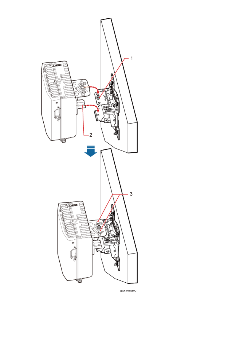
Figure 8-16 Installing the BTS3902E onto the main mounting bracket
(1) Upper positioning pin (2) Lower positioning pin (3) Positioning screw
Step 7 Adjust the installation angle of the BTS3902E: horizontal angle ±30°, vertical angle ±10°.
BTS3902E WCDMA
Installation Guide
8 Installing a BTS3902E (using angle-adjustable mounting
kits)
Issue 10 (2014-05-16) Huawei Proprietary and Confidential
Copyright © Huawei Technologies Co., Ltd.
86
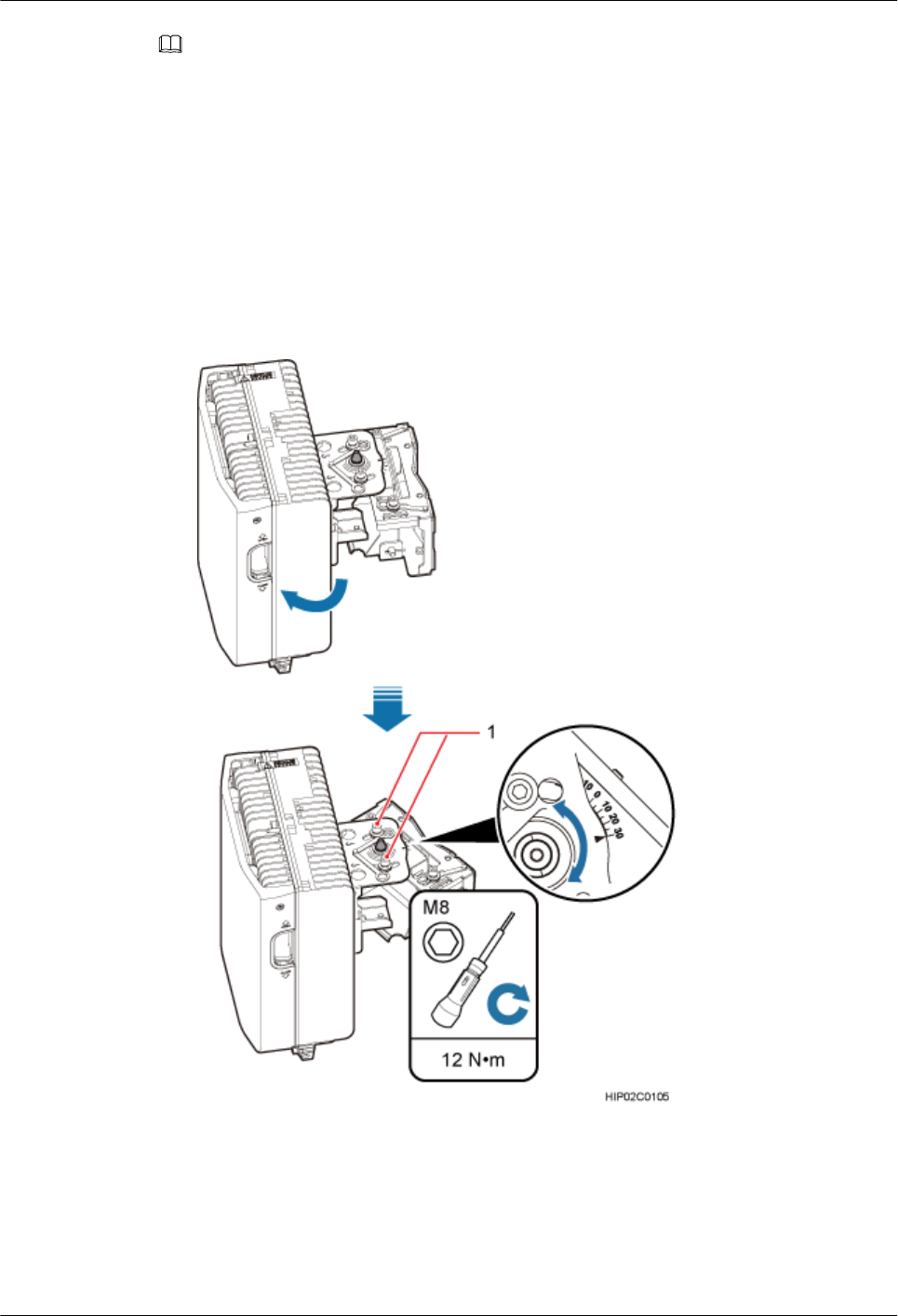
NOTE
lIf the positioning pin is tightened too hard, the installation angle cannot be adjusted. In this case, loosen the
positioning screw first.
lThe horizontal angle and vertical angle can be adjusted simultaneously. The vertical angle can be determined
either from the plan or elevation view.
lAdjust the horizontal angle.
1. Hold the BTS3902E to adjust the horizontal angle to a proper degree.
2. Use an M8 inner hexagon torque screwdriver to tighten the positioning screw to 12 N·m
(106.21 lbf·in.), as shown in Figure 8-17.
Figure 8-17 Adjusting the horizontal angle
(1) Positioning screw
lAdjust the vertical angle. Figure 8-18 shows the vertical angle from the plan view. If the
vertical angle is from the elevation view, adjust the angle to the opposite direction.
BTS3902E WCDMA
Installation Guide
8 Installing a BTS3902E (using angle-adjustable mounting
kits)
Issue 10 (2014-05-16) Huawei Proprietary and Confidential
Copyright © Huawei Technologies Co., Ltd.
87
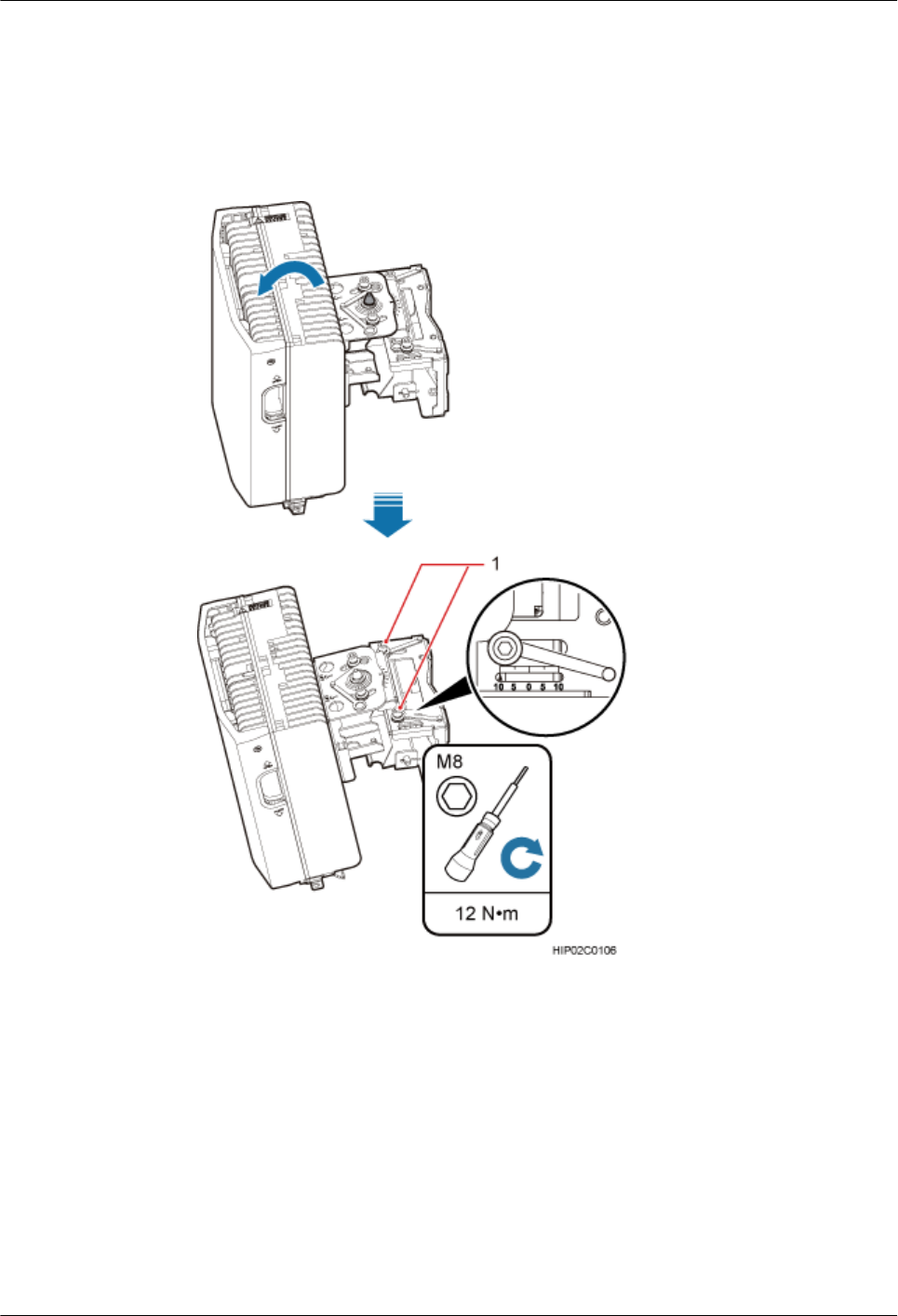
1. Hold the BTS3902E to adjust the vertical angle from the plan view or elevation view to
proper degrees.
2. Use an M8 inner hexagon torque screwdriver to tighten the positioning screw to 12 N·m
(106.21 lbf·in.).
Figure 8-18 Adjusting the vertical angle
(1) Positioning screw
Step 8 Ensure that the positioning screws both in the vertical direction and horizontal direction have
been secured. Tighten the positioning screws in both directions simultaneously.
----End
BTS3902E WCDMA
Installation Guide
8 Installing a BTS3902E (using angle-adjustable mounting
kits)
Issue 10 (2014-05-16) Huawei Proprietary and Confidential
Copyright © Huawei Technologies Co., Ltd.
88
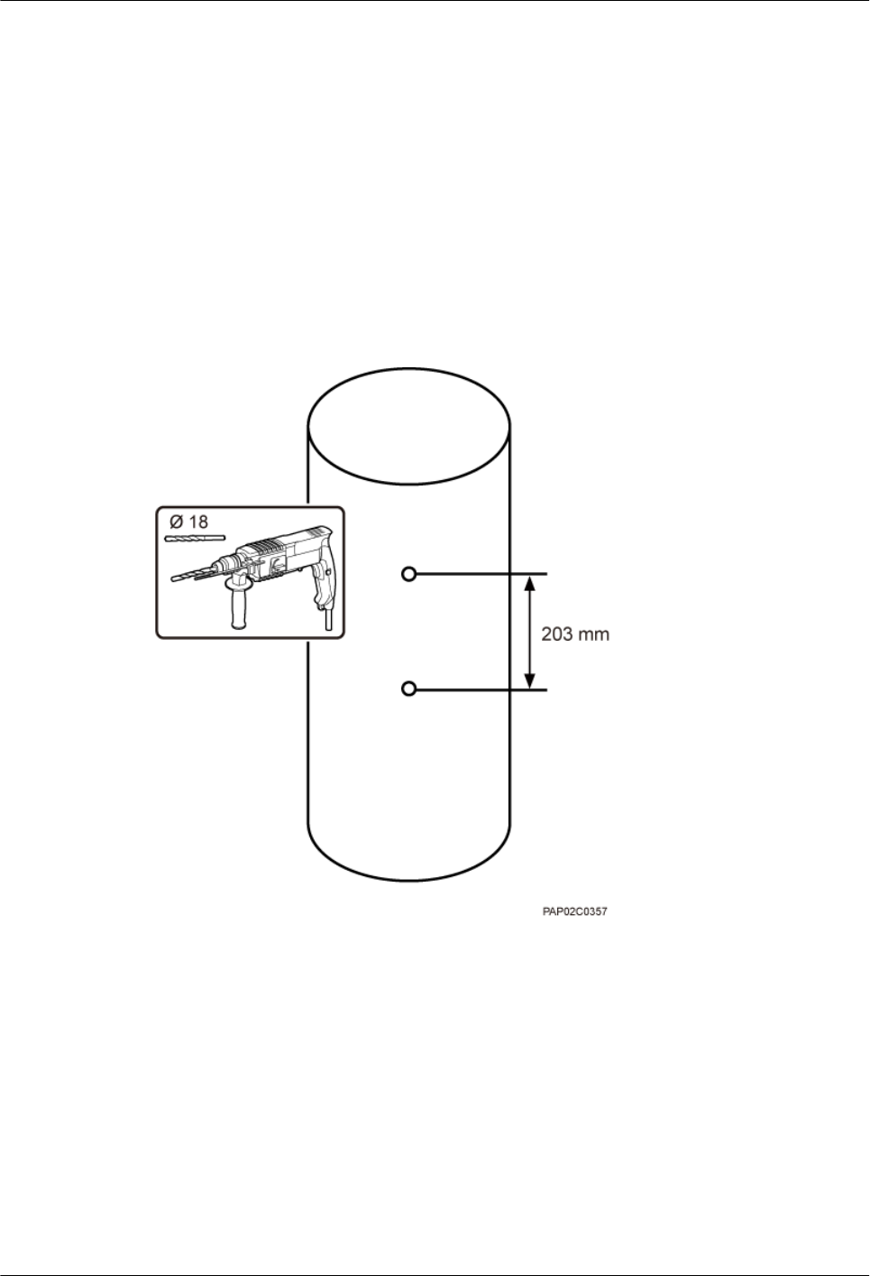
8.4 Installing a BTS3902E on a Wood Pole with the Diameter
of 200 mm to 400 mm (7.87 in. to 15.75 in.)
This section describes the procedure and precautions for installing a BTS3902E on a wood pole.
Procedure
Step 1 Drill holes. Drill two holes with the diameter of 18 mm (0.71 in.) through the middle axis of the
wood pole, ensuring that the inter-hole spacing is 203 mm (7.99 in.), as shown in Figure 8-19.
Figure 8-19 Drilling holes
Step 2 Install an adapting plate both on the top and bottom of the main mounting bracket. Tighten two
M6x14 screws to 5 N·m (44.25 lbf·in.) to secure each of the plates, as shown in Figure 8-20.
BTS3902E WCDMA
Installation Guide
8 Installing a BTS3902E (using angle-adjustable mounting
kits)
Issue 10 (2014-05-16) Huawei Proprietary and Confidential
Copyright © Huawei Technologies Co., Ltd.
89
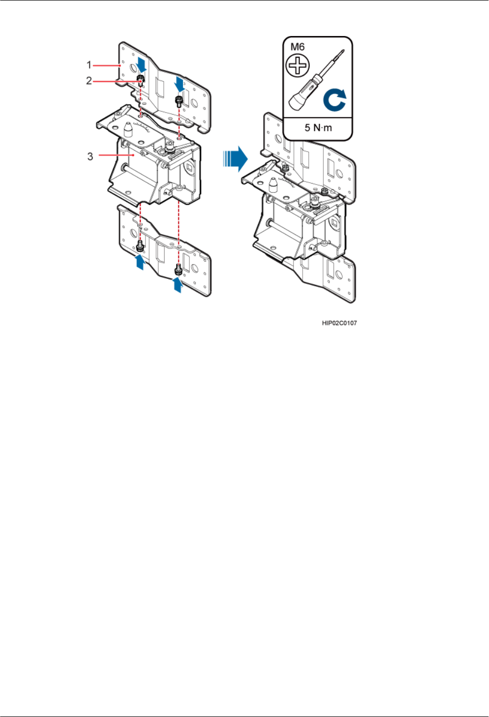
Figure 8-20 Installing the adapting plate assembly
(1) Adapting plate (2) Screw (3) Main mounting bracket
Step 3 Install the mounting piece, as shown in Figure 8-21.
1. Align the mounting hole group C with the mounting holes in the wood pole.
2. Put the two long M16 bolts with spacers through the upper and lower mounting holes.
BTS3902E WCDMA
Installation Guide
8 Installing a BTS3902E (using angle-adjustable mounting
kits)
Issue 10 (2014-05-16) Huawei Proprietary and Confidential
Copyright © Huawei Technologies Co., Ltd.
90
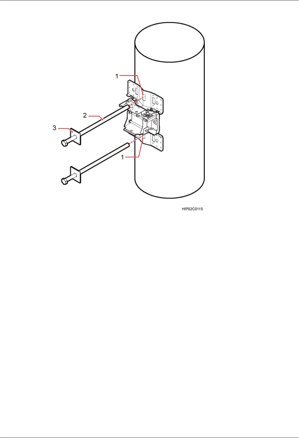
Figure 8-21 Installing the mounting piece
(1) Mounting hole group C (2) Bolt (3) Spacer
Step 4 Tighten the nuts to 80 N·m (708.06 lbf·in.), as shown in Figure 8-22.
BTS3902E WCDMA
Installation Guide
8 Installing a BTS3902E (using angle-adjustable mounting
kits)
Issue 10 (2014-05-16) Huawei Proprietary and Confidential
Copyright © Huawei Technologies Co., Ltd.
91
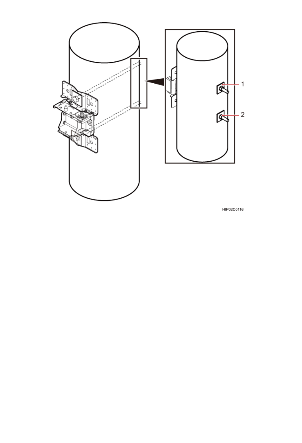
Figure 8-22 Tightening nuts
(1) Spacer (2) Nut
Step 5 Install the BTS3902E onto the main mounting bracket vertically. Put the upper positioning pin
through the hole on the attachment plate and the lower positioning pin through the hole on the
main mounting bracket, pre-tighten the positioning screws, as shown in Figure 8-23.
BTS3902E WCDMA
Installation Guide
8 Installing a BTS3902E (using angle-adjustable mounting
kits)
Issue 10 (2014-05-16) Huawei Proprietary and Confidential
Copyright © Huawei Technologies Co., Ltd.
92
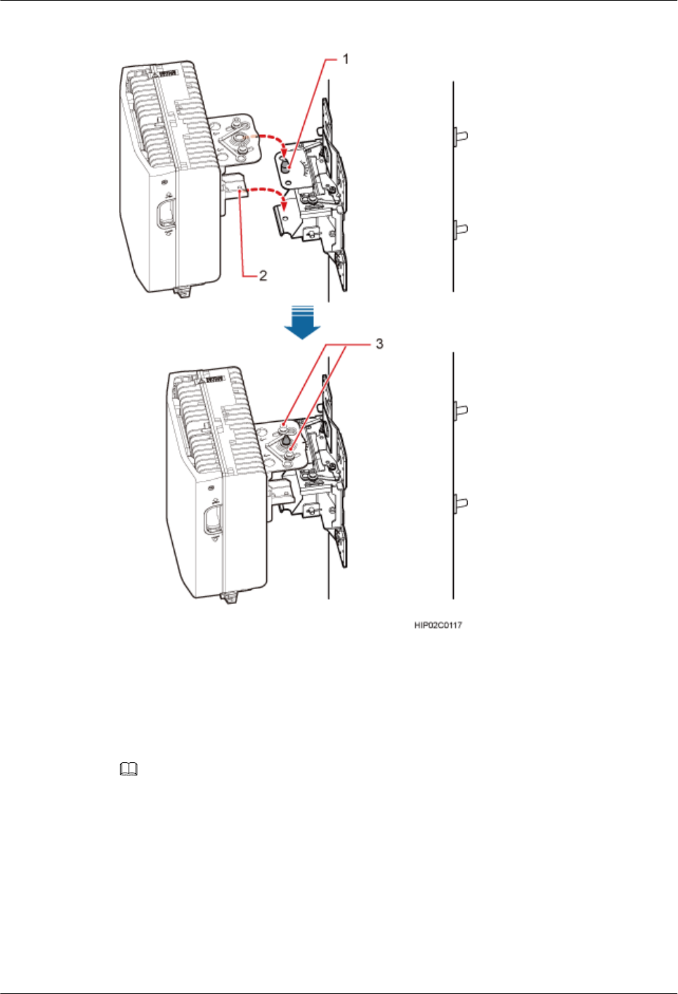
Figure 8-23 Installing the BTS3902E onto the main mounting bracket
(1) Upper positioning pin (2) Lower positioning pin (3) Positioning screw
Step 6 Adjust the installation angle of the BTS3902E: horizontal angle ±30°, vertical angle ±10°.
NOTE
lIf the positioning pin is tightened too hard, the installation angle cannot be adjusted. In this case, loosen the
positioning screw first.
lThe horizontal angle and vertical angle can be adjusted simultaneously. The vertical angle can be determined
either from the plan or elevation view.
lAdjust the horizontal angle.
1. Hold the BTS3902E to adjust the horizontal angle to a proper degree.
2. Use an M8 inner hexagon torque screwdriver to tighten the positioning screw to 12 N·m
(106.21 lbf·in.), as shown in Figure 8-24.
BTS3902E WCDMA
Installation Guide
8 Installing a BTS3902E (using angle-adjustable mounting
kits)
Issue 10 (2014-05-16) Huawei Proprietary and Confidential
Copyright © Huawei Technologies Co., Ltd.
93

Figure 8-24 Adjusting the horizontal angle
(1) Positioning screw
lAdjust the vertical angle. Figure 8-25 shows the vertical angle from the plan view. If the
vertical angle is from the elevation view, adjust the angle to the opposite direction.
1. Hold the BTS3902E to adjust the vertical angle from the plan view or elevation view to
proper degrees.
2. Use an M8 inner hexagon torque screwdriver to tighten the positioning screw to 12 N·m
(106.21 lbf·in.).
BTS3902E WCDMA
Installation Guide
8 Installing a BTS3902E (using angle-adjustable mounting
kits)
Issue 10 (2014-05-16) Huawei Proprietary and Confidential
Copyright © Huawei Technologies Co., Ltd.
94

Figure 8-25 Adjusting the vertical angle
(1) Positioning screw
Step 7 Ensure that the positioning screws both in the vertical direction and horizontal direction have
been secured. Tighten the positioning screws in both directions simultaneously.
----End
BTS3902E WCDMA
Installation Guide
8 Installing a BTS3902E (using angle-adjustable mounting
kits)
Issue 10 (2014-05-16) Huawei Proprietary and Confidential
Copyright © Huawei Technologies Co., Ltd.
95

9 (Optional) Installing the AC Surge
Protection Box and Cables
About This Chapter
This chapter describes the dimensions, installation clearance requirements, and installation
options of an AC surge protection box as well as the procedure for installing the surge protection
box. The AC surge protection box can be configured when the BTS3902E is installed outdoors.
Two types of surge protection boxes SPD60D and SPM60A are available for the BTS3902E.
9.1 Installing the SPD60D and Cables (Working at the 1.9 GHz or 2.1 GHz Frequency Band)
This section describes the dimensions and installation clearance requirements, installation
scenarios, and installation process of an SPD60D that is configured for the BTS3902E working
at the 1.9 GHz or 2.1 GHz frequency band.
9.2 Installing the SPM60A and Cables (Working at the 850 MHz Frequency Band)
This section describes the dimensions and installation clearance requirements, installation
options, and installation process of an SPD60D that is configured for the BTS3902E working
at the 850 MHz frequency band.
BTS3902E WCDMA
Installation Guide
9 (Optional) Installing the AC Surge Protection Box and
Cables
Issue 10 (2014-05-16) Huawei Proprietary and Confidential
Copyright © Huawei Technologies Co., Ltd.
96
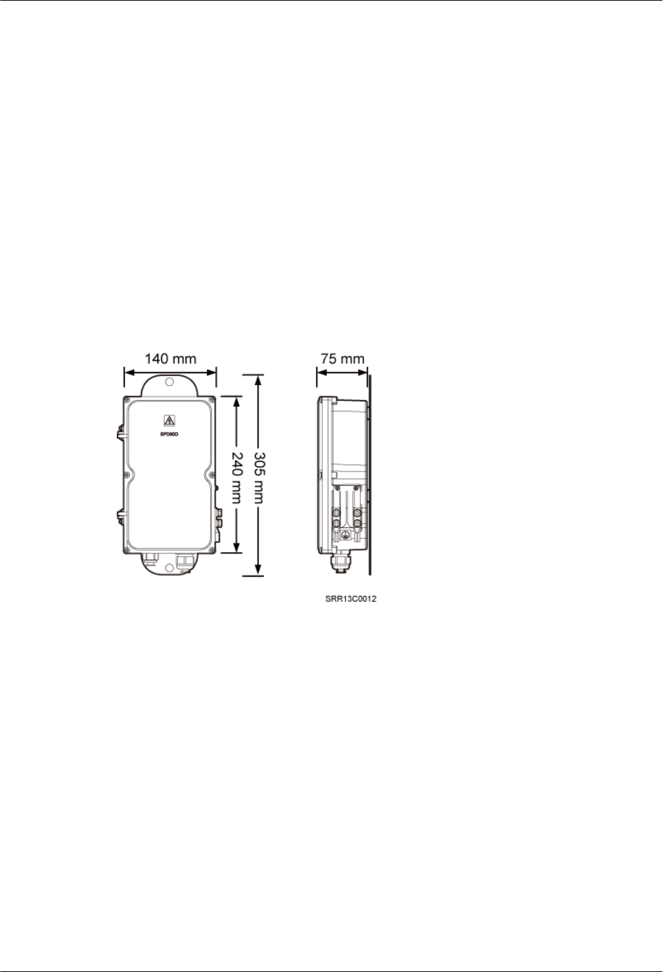
9.1 Installing the SPD60D and Cables (Working at the 1.9
GHz or 2.1 GHz Frequency Band)
This section describes the dimensions and installation clearance requirements, installation
scenarios, and installation process of an SPD60D that is configured for the BTS3902E working
at the 1.9 GHz or 2.1 GHz frequency band.
9.1.1 Dimensions and Installation Clearance Requirements of an
SPD60D
This section describes the dimensions and installation clearance requirements for an SPD60D.
Figure 9-1 shows the dimensions of an SPD60D.
Figure 9-1 Dimensions of an SPD60D
Figure 9-2 shows the recommended installation clearance for an SPD60D.
BTS3902E WCDMA
Installation Guide
9 (Optional) Installing the AC Surge Protection Box and
Cables
Issue 10 (2014-05-16) Huawei Proprietary and Confidential
Copyright © Huawei Technologies Co., Ltd.
97
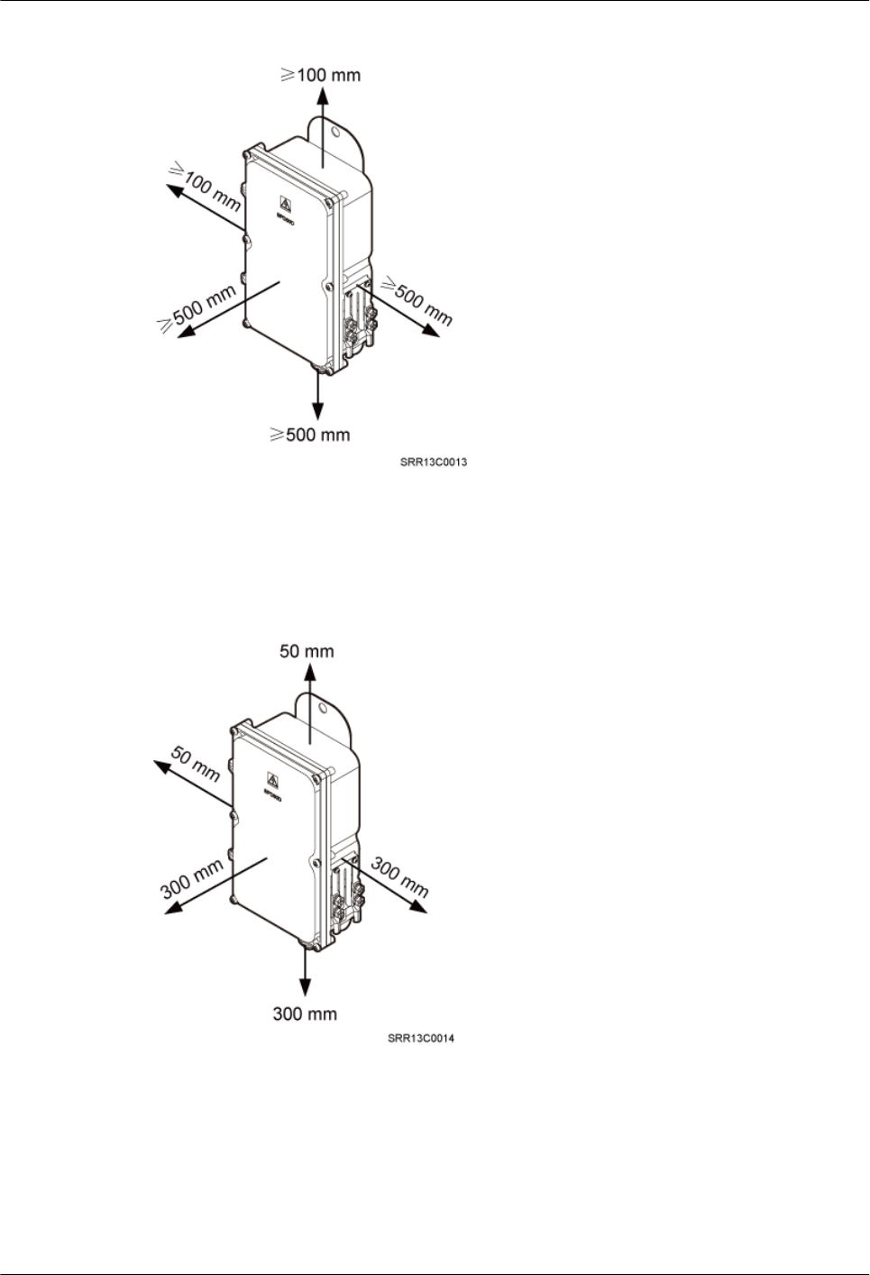
Figure 9-2 Recommended installation clearance for an SPD60D
Figure 9-3 shows the minimum installation clearance for an SPD60D.
Figure 9-3 Minimum installation clearance for an SPD60D
9.1.2 Installation Options of an SPD60D
This section describes installation options of an SPD60D. An SPD60D can be installed on a
pole, wall, or wood pole.
BTS3902E WCDMA
Installation Guide
9 (Optional) Installing the AC Surge Protection Box and
Cables
Issue 10 (2014-05-16) Huawei Proprietary and Confidential
Copyright © Huawei Technologies Co., Ltd.
98
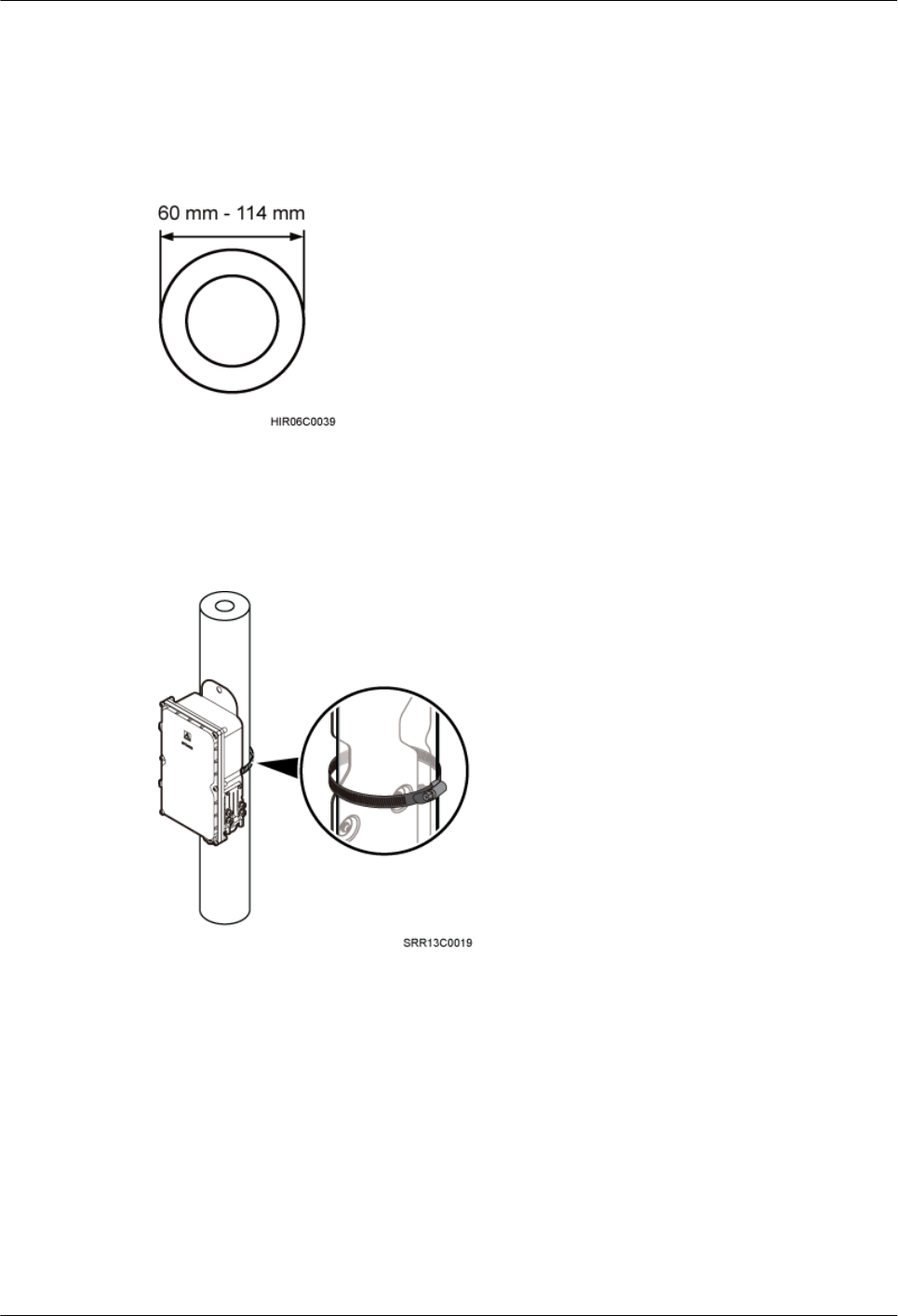
Installing an SPD60D on a Pole with the Diameter of 60 mm to 114 mm (2.36 in. to
4.49 in.)
Figure 9-4 shows the diameter of a pole for installing an SPD60D.
Figure 9-4 Diameter of a pole
Figure 9-5 shows an SPD60D installed on a pole.
Figure 9-5 An SPD60D installed on a pole
Installing an SPD60D on a Pole with the Diameter of 114 mm to 400 mm (4.49 in.
to 15.75 in.)
Figure 9-6 shows the diameter of a pole for installing an SPD60D.
BTS3902E WCDMA
Installation Guide
9 (Optional) Installing the AC Surge Protection Box and
Cables
Issue 10 (2014-05-16) Huawei Proprietary and Confidential
Copyright © Huawei Technologies Co., Ltd.
99
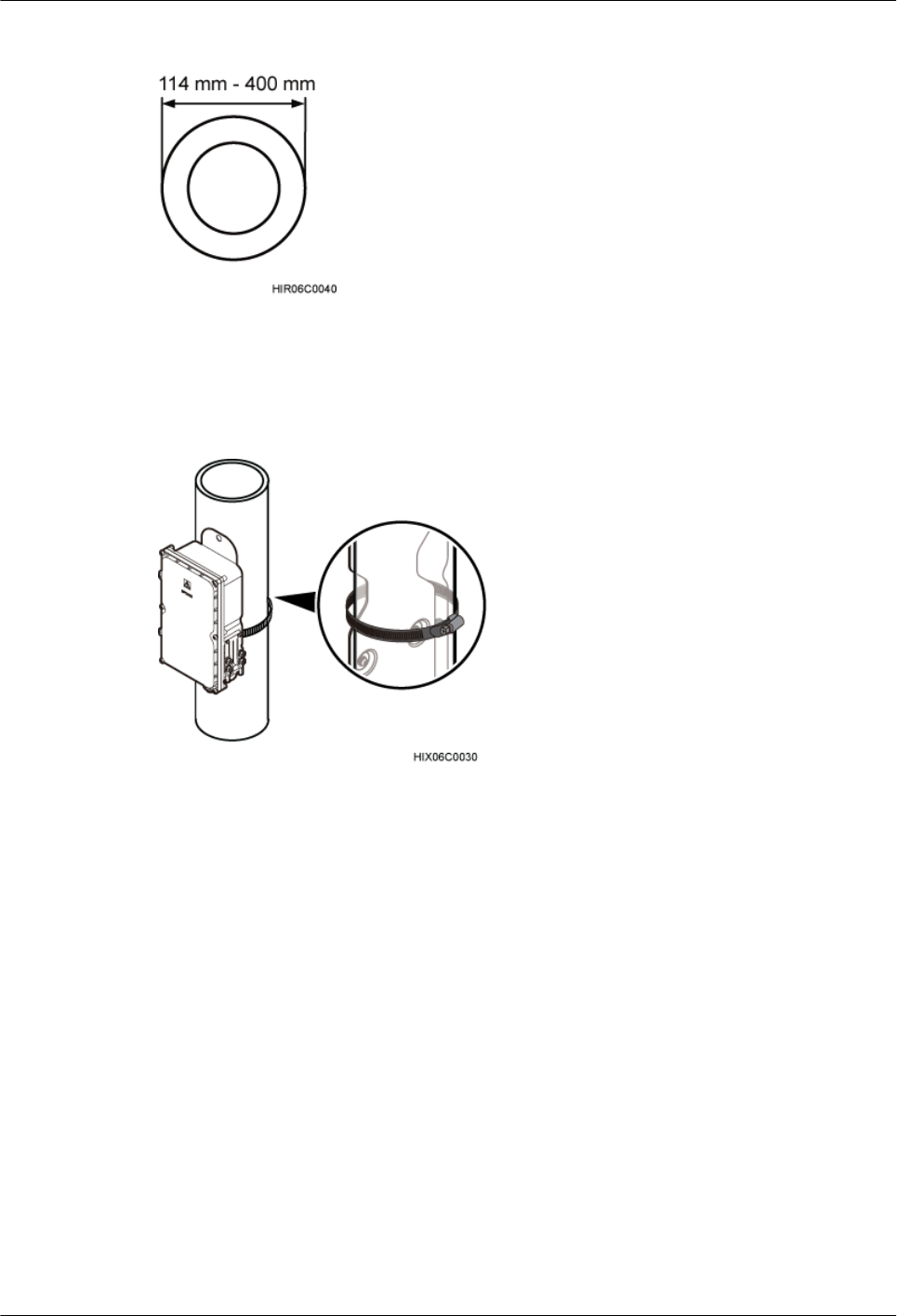
Figure 9-6 Diameter of a pole
Figure 9-7 shows an SPD60D installed on a pole.
Figure 9-7 An SPD60D installed on a pole
Installing an SPD60D on a Wall
Figure 9-8 shows an SPD60D installed on a wall.
BTS3902E WCDMA
Installation Guide
9 (Optional) Installing the AC Surge Protection Box and
Cables
Issue 10 (2014-05-16) Huawei Proprietary and Confidential
Copyright © Huawei Technologies Co., Ltd.
100
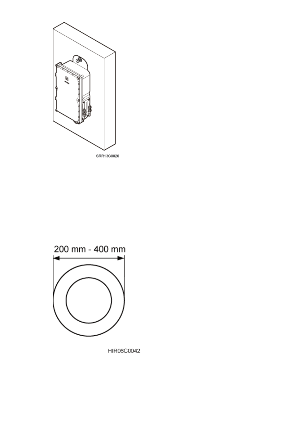
Figure 9-8 An SPD60D installed on a wall
Installing an SPD60D on a Wood Pole with the Diameter of 200 mm to 400 mm (7.87
in. to 15.75 in.)
Figure 9-9 shows the diameter of a wood pole for installing an SPD60D.
Figure 9-9 Diameter of a pole
Figure 9-10 shows an SPD60D installed on a wood pole.
BTS3902E WCDMA
Installation Guide
9 (Optional) Installing the AC Surge Protection Box and
Cables
Issue 10 (2014-05-16) Huawei Proprietary and Confidential
Copyright © Huawei Technologies Co., Ltd.
101
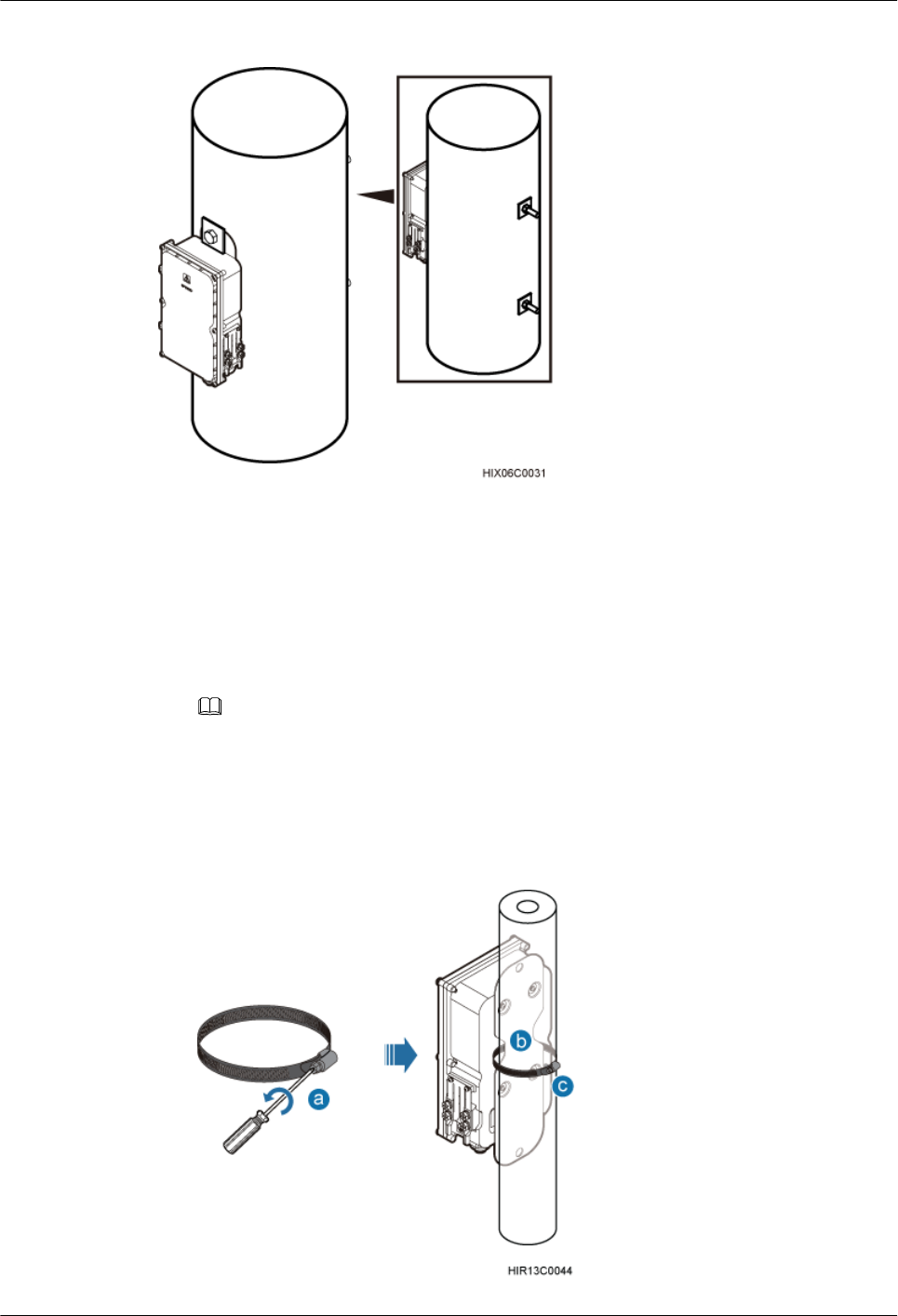
Figure 9-10 An SPD60D installed on a wood pole
9.1.3 Installing an SPD60D
This section describes the procedure for installing an SPD60D.
Procedure
lInstall an SPD60D on a pole, as shown in Figure 9-11.
NOTE
lWhen the diameter of the pole ranges from 60 mm to 114 mm (2.36 in. to 4.49 in.), the hose clamps
delivered with theSPD60D is used.
lWhen the diameter of the pole ranges from 114 mm to 400 mm (4.49 in. to 15.75 in.), the hose clamps
purchased locally is used.
Figure 9-11 Installing the SPD60D on a pole
BTS3902E WCDMA
Installation Guide
9 (Optional) Installing the AC Surge Protection Box and
Cables
Issue 10 (2014-05-16) Huawei Proprietary and Confidential
Copyright © Huawei Technologies Co., Ltd.
102
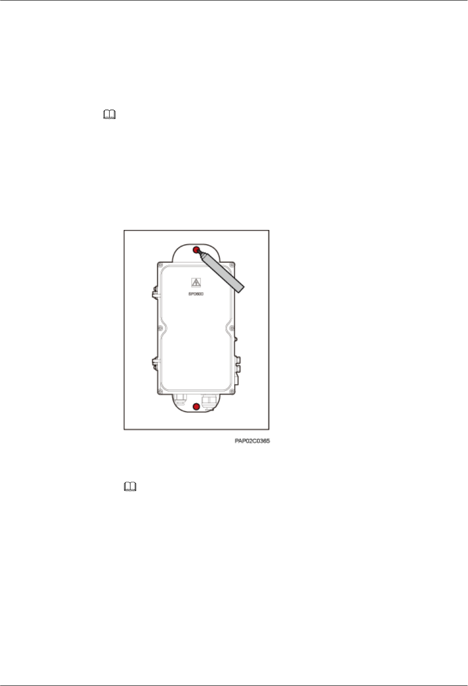
1. Loosen the hose clamp.
2. Lead the clamp through the gap between the rear mounting plate and the case of the
SPD60D.
3. Install the hose clamp around the pole, and tighten the screw to 4.5 N·m (39.83 lbf·in.)
to secure the clamp.
NOTE
If the diameter of the pole around which the clamp is installed is small, cut the extra part of the clamp.
lInstall an SPD60D on a wall.
1. Place the rear mounting plate of the SPD60D against the wall, use a level to verify
that the plate is horizontal, and then mark anchor points using a marker, as shown in
Figure 9-12.
Figure 9-12 Marking the anchor points
2. Use a hammer drill with a Ø14 bit to drill holes at the anchor points, and install
expansion bolts, as shown in Figure 9-13.
NOTE
After disassembling the expansion bolt assemblies, discard the plastic tubes.
BTS3902E WCDMA
Installation Guide
9 (Optional) Installing the AC Surge Protection Box and
Cables
Issue 10 (2014-05-16) Huawei Proprietary and Confidential
Copyright © Huawei Technologies Co., Ltd.
103
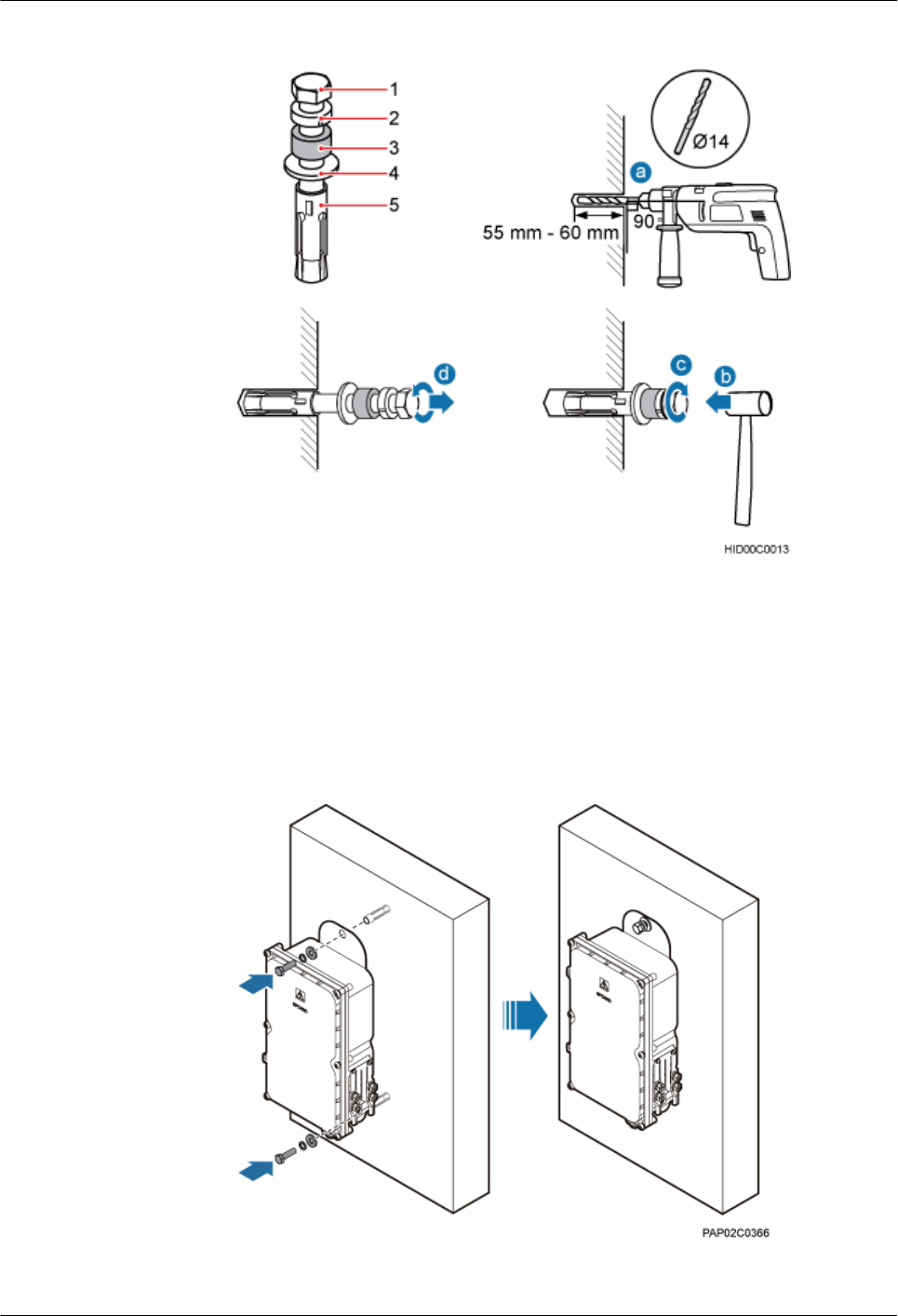
Figure 9-13 Installing an expansion bolt
(1) M10x65 bolt (2) Spring washer 10 (3) Plastic tube (4) Flat washer 10 (5) Expansion tube
3. Align the SPD60D with the holes in the wall, and tighten the expansion bolts to 30
N·m (265.52 lbf·in.), as shown in Figure 9-14.
Figure 9-14 Installing an SPD60D
lInstall an SPD60D on a wood pole.
BTS3902E WCDMA
Installation Guide
9 (Optional) Installing the AC Surge Protection Box and
Cables
Issue 10 (2014-05-16) Huawei Proprietary and Confidential
Copyright © Huawei Technologies Co., Ltd.
104
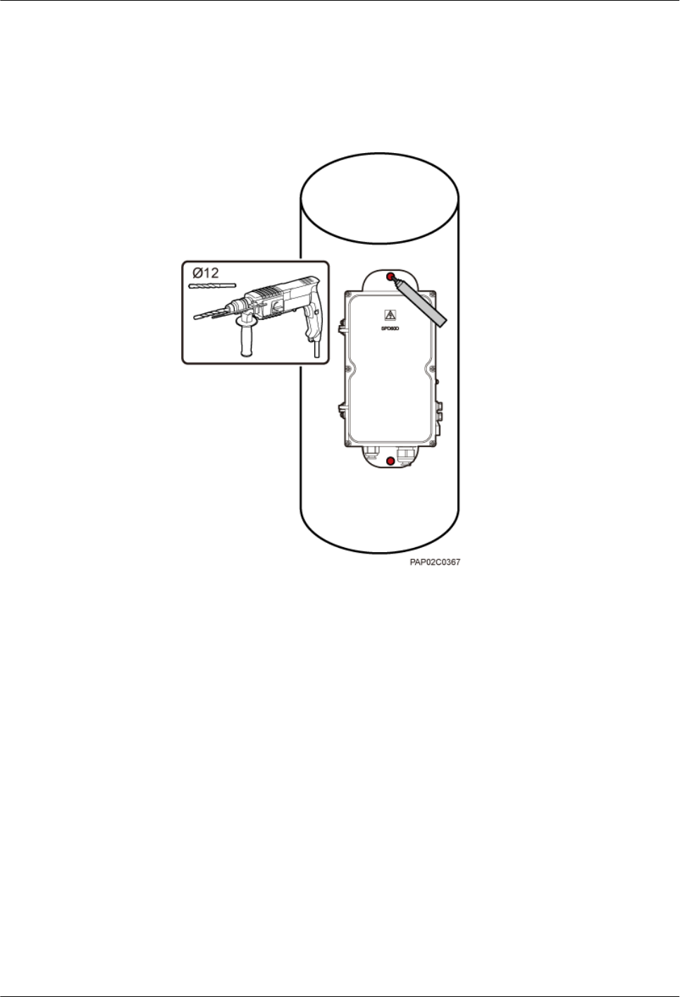
1. Place the rear mounting plate of the SPD60D against the wood pole, determine the
anchor points on the middle axis, and then mark the anchor points.
2. Drill holes with the diameter of 12 mm (0.47 in.) at the anchor points through the
wood pole, as shown in Figure 9-15.
Figure 9-15 Drilling holes
3. Align the SPD60D with the holes in the wood pole, lead the two long M10 bolts with
spacers through the two mounting holes and holes, and then install the bolts on the
wood pole, as shown in Figure 9-16.
BTS3902E WCDMA
Installation Guide
9 (Optional) Installing the AC Surge Protection Box and
Cables
Issue 10 (2014-05-16) Huawei Proprietary and Confidential
Copyright © Huawei Technologies Co., Ltd.
105
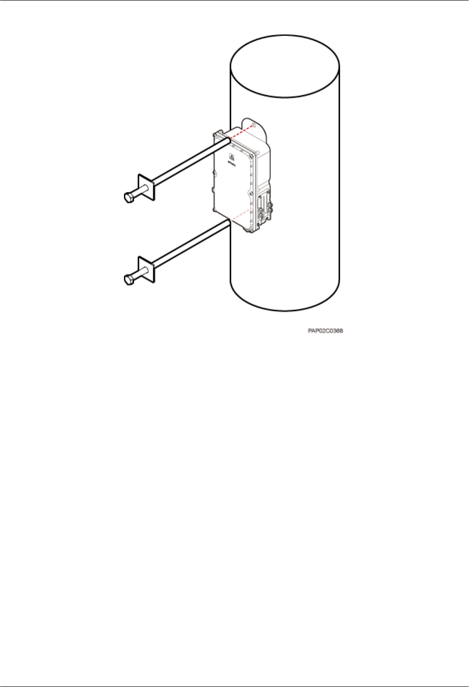
Figure 9-16 Installing the SPD60D on the wood pole
4. Tighten the nuts to 30 N·m (265.52 lbf·in.), as shown in Figure 9-17.
BTS3902E WCDMA
Installation Guide
9 (Optional) Installing the AC Surge Protection Box and
Cables
Issue 10 (2014-05-16) Huawei Proprietary and Confidential
Copyright © Huawei Technologies Co., Ltd.
106
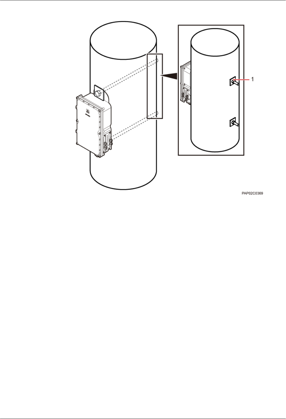
Figure 9-17 Tightening the nuts
(1) Nut
----End
9.1.4 Installing Cables for an SPD60D
This section describes the procedure for installing cables for an SPD60D.
Prerequisites
Prepare OT terminals for connecting one end of a power cable to an SPD60D. For details, see
14.1.1 Preparing OT Terminals of the AC Input Power Cable to the SPD60D.
Procedure
Step 1 Loosen the screws on the SPD60D using the M4 Phillips screwdriver and open the cover plate.
Then, remove the thread-lock sealing nut from the PG connector of the surge protection box,
and discard waterproof blocks, as shown in Figure 9-18.
BTS3902E WCDMA
Installation Guide
9 (Optional) Installing the AC Surge Protection Box and
Cables
Issue 10 (2014-05-16) Huawei Proprietary and Confidential
Copyright © Huawei Technologies Co., Ltd.
107
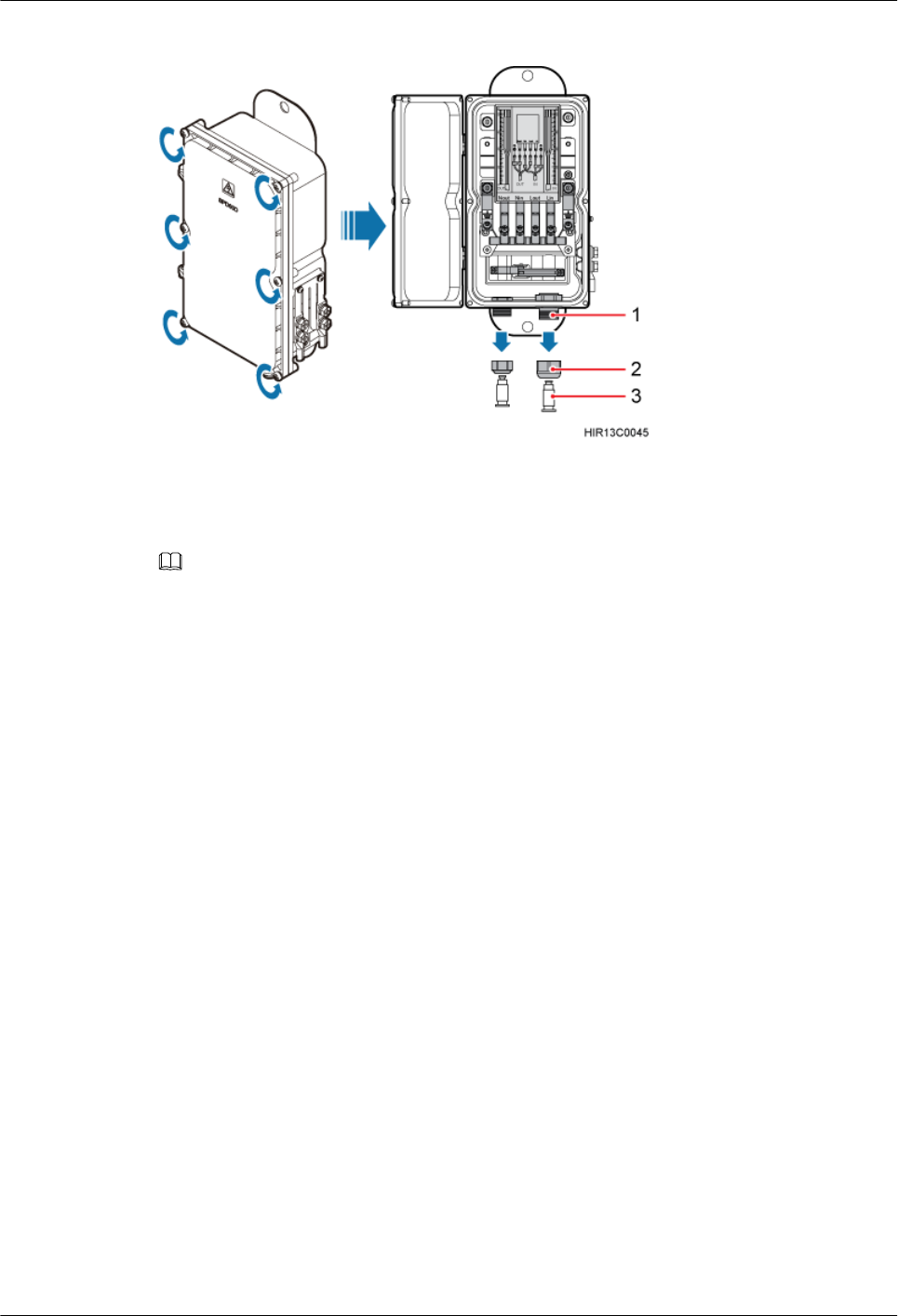
Figure 9-18 Opening the cover plate of the SPD60D
(1) PG connector (2) Thread-lock sealing nut of the PG connector (3) Waterproof block
NOTE
Do not use the removed thread-lock sealing nut of the PG connector with the thread-lock sealing nuts on
other surge protection boxes.
Step 2 Glide the thread-lock sealing nut and then the PG connector over the power cable.
Step 3 Connect power cables to the SPD60D, as shown in Figure 9-19. Connect the power cable
between the BTS3902E and the surge protection box to the port on the left, and the power cable
between the surge protection box and the external power equipment to the port on the right.
BTS3902E WCDMA
Installation Guide
9 (Optional) Installing the AC Surge Protection Box and
Cables
Issue 10 (2014-05-16) Huawei Proprietary and Confidential
Copyright © Huawei Technologies Co., Ltd.
108
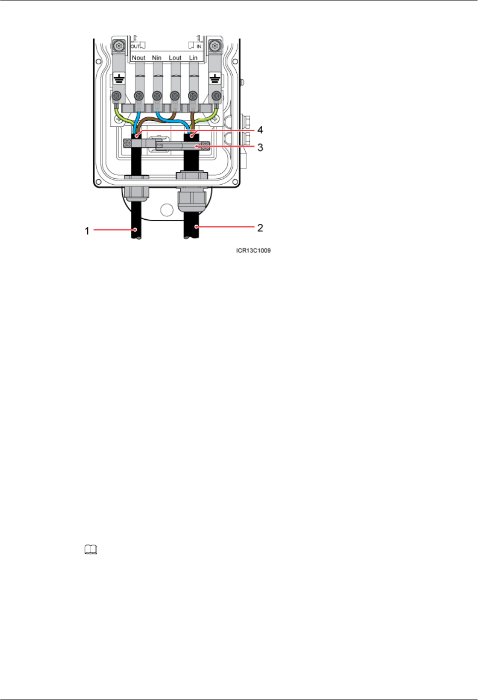
Figure 9-19 Cable connections of an SPD60D
(1) Power cable between the BTS3902E
and the surge protection box
(2) Power cable between the surge
protection box and the external power
equipment
(3) Clip (4) Insulation layer
1. Lead the power cable between the surge protection box and the external power equipment
through the PG connector labeled IN. Connect the OT terminals of the blue, brown, and
yellow/green core wires to the Lin, Nin, and GND ports on the surge protection box
respectively.
2. Lead the power cable between the BTS3902E and the SPD60D through the PG connector
labeled OUT. Connect the OT terminals of the blue, brown, and yellow/green core wires
to the Nout, Lout, and GND ports on the surge protection box respectively.
3. Tighten the thread-lock sealing nut of the PG connector, and then use a torque wrench to
tighten the PG connector to ensure proper waterproofing.
lTighten the PG connector of the power cable between the power module of the
BTS3902E and the surge protection box to 1.2 N·m (10.62 lbf·in.).
lTighten the PG connector of the power cable between the surge protector and the
external power equipment to 1.5 N·m (13.28 lbf·in.).
Step 4 Fasten the power cables using clips.
NOTE
Ensure that the insulation layer of each power cable is fastened using clips.
Step 5 Close the cover plate of the surge protection box and tighten the screw to 1.4 N·m (12.39 lbf.in.)
using an M4 Phillips screwdriver, as shown in Figure 9-20.
BTS3902E WCDMA
Installation Guide
9 (Optional) Installing the AC Surge Protection Box and
Cables
Issue 10 (2014-05-16) Huawei Proprietary and Confidential
Copyright © Huawei Technologies Co., Ltd.
109
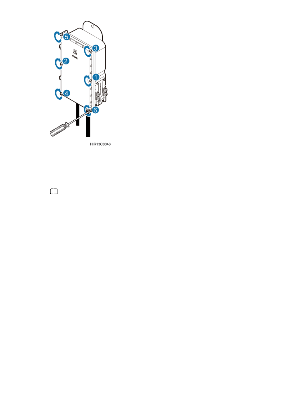
Figure 9-20 Closing the cover plate of the SPD60D
Step 6 Wrap waterproof tape and then PVC insulation tape around both ends of each power cable and
connectors between corrugated pipes, as shown in Figure 9-21.
NOTE
lBefore wrapping the waterproof tape, stretch the tape evenly until the length of the tape is twice its original
length.
lBefore wrapping the PVC insulation tape, do not stretch the PVC insulation tape.
lEnsure that each layer of tape overlaps more than 50% of the preceding layer. Stretch and press the tape
tightly to avoid wrinkles or spaces. Ensure that the tape is tightly wrapped and stuck and will not fall off.
lEnsure that the adhesive surface of the tape overlaps the lower layer.
lCutting the cable ties at the position of 3 mm (0.12 in.) to 5 mm (0.20 in.) far from the head.
BTS3902E WCDMA
Installation Guide
9 (Optional) Installing the AC Surge Protection Box and
Cables
Issue 10 (2014-05-16) Huawei Proprietary and Confidential
Copyright © Huawei Technologies Co., Ltd.
110
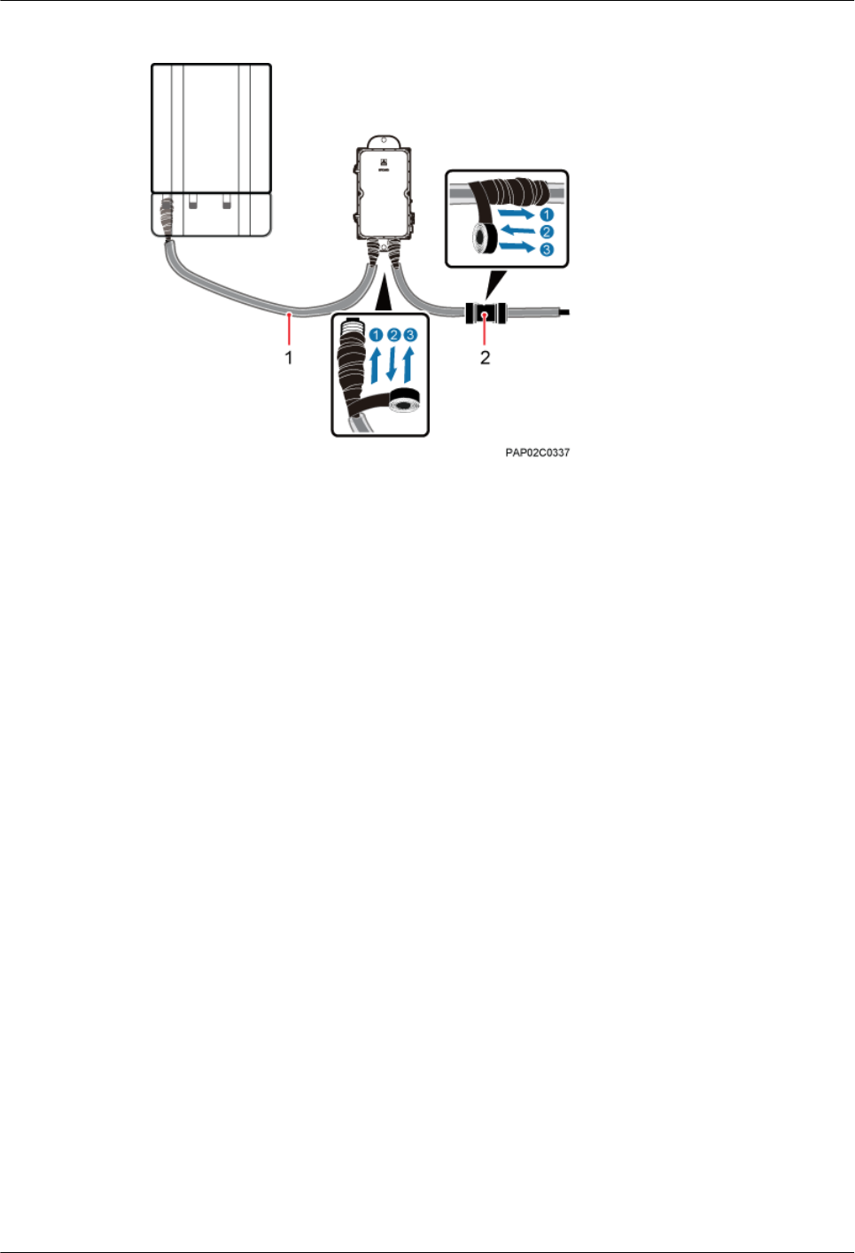
Figure 9-21 Fastening AC power cables
(1) Corrugated pipe (2) Connector between corrugated pipes
Step 7 Bind the cables using cable ties at equal spacing of 30 cm (11.81 in.) and verify that the bend
radius of the corrugated pipe is not less than 60 mm (2.36 in.).
Step 8 Install the equipotential cable and PGND cable, as shown in Figure 9-22.
BTS3902E WCDMA
Installation Guide
9 (Optional) Installing the AC Surge Protection Box and
Cables
Issue 10 (2014-05-16) Huawei Proprietary and Confidential
Copyright © Huawei Technologies Co., Ltd.
111
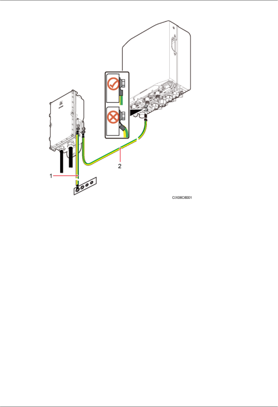
Figure 9-22 Installing a PGND Cable and an Equipotential Cable
(1) PGND cable (2) Equipotential cable
----End
9.2 Installing the SPM60A and Cables (Working at the 850
MHz Frequency Band)
This section describes the dimensions and installation clearance requirements, installation
options, and installation process of an SPD60D that is configured for the BTS3902E working
at the 850 MHz frequency band.
9.2.1 Dimensions and Installation Clearance Requirements of an
SPM60A
This section describes the dimensions and installation clearance requirements for an SPM60A.
Figure 9-23 shows the dimensions of an SPM60A.
BTS3902E WCDMA
Installation Guide
9 (Optional) Installing the AC Surge Protection Box and
Cables
Issue 10 (2014-05-16) Huawei Proprietary and Confidential
Copyright © Huawei Technologies Co., Ltd.
112
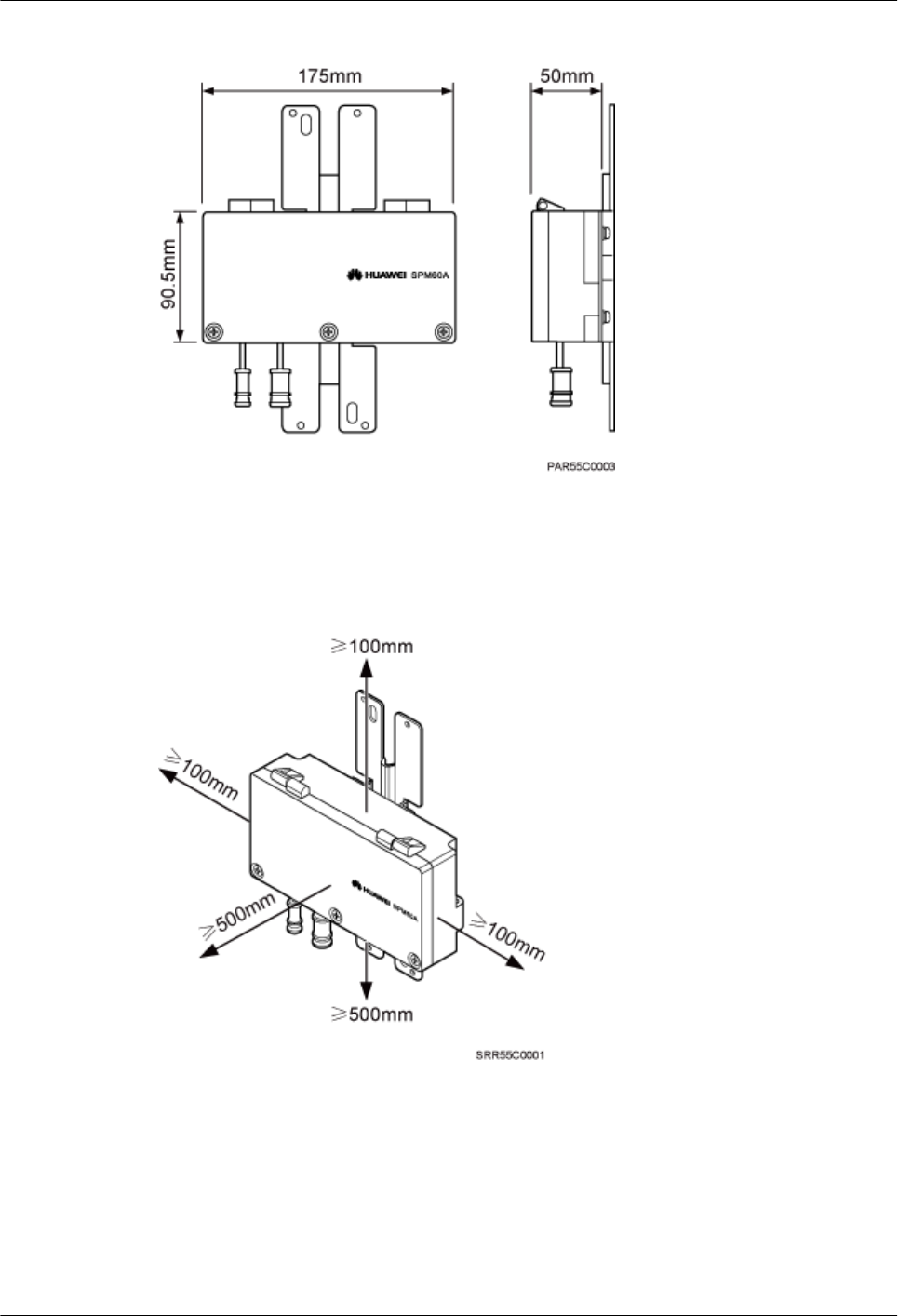
Figure 9-23 Dimensions of an SPM60A
Figure 9-24 shows the recommended installation clearance for an SPM60A.
Figure 9-24 Recommended installation clearance for an SPM60A
Figure 9-25 shows the minimum installation clearance for an SPM60A.
BTS3902E WCDMA
Installation Guide
9 (Optional) Installing the AC Surge Protection Box and
Cables
Issue 10 (2014-05-16) Huawei Proprietary and Confidential
Copyright © Huawei Technologies Co., Ltd.
113
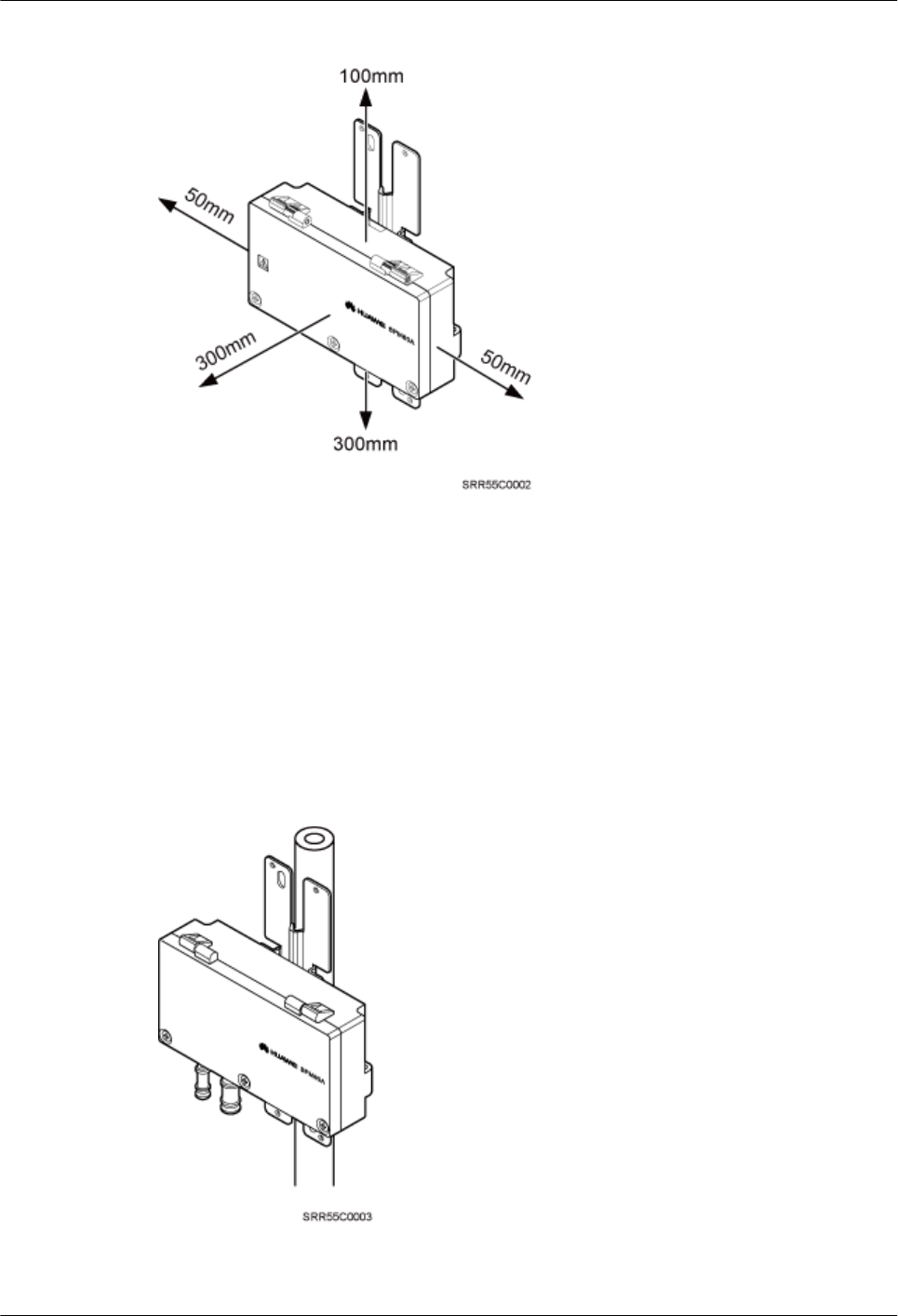
Figure 9-25 Minimum installation clearance for an SPM60A
9.2.2 Installation Options of an SPM60A
This section describes installation options of an SPM60A. An SPM60A can be installed on a
pole, or wall.
Installing an SPM60A on a Pole
Figure 9-26 shows an SPM60A installed on a pole.
Figure 9-26 An SPM60A installed on a pole
BTS3902E WCDMA
Installation Guide
9 (Optional) Installing the AC Surge Protection Box and
Cables
Issue 10 (2014-05-16) Huawei Proprietary and Confidential
Copyright © Huawei Technologies Co., Ltd.
114
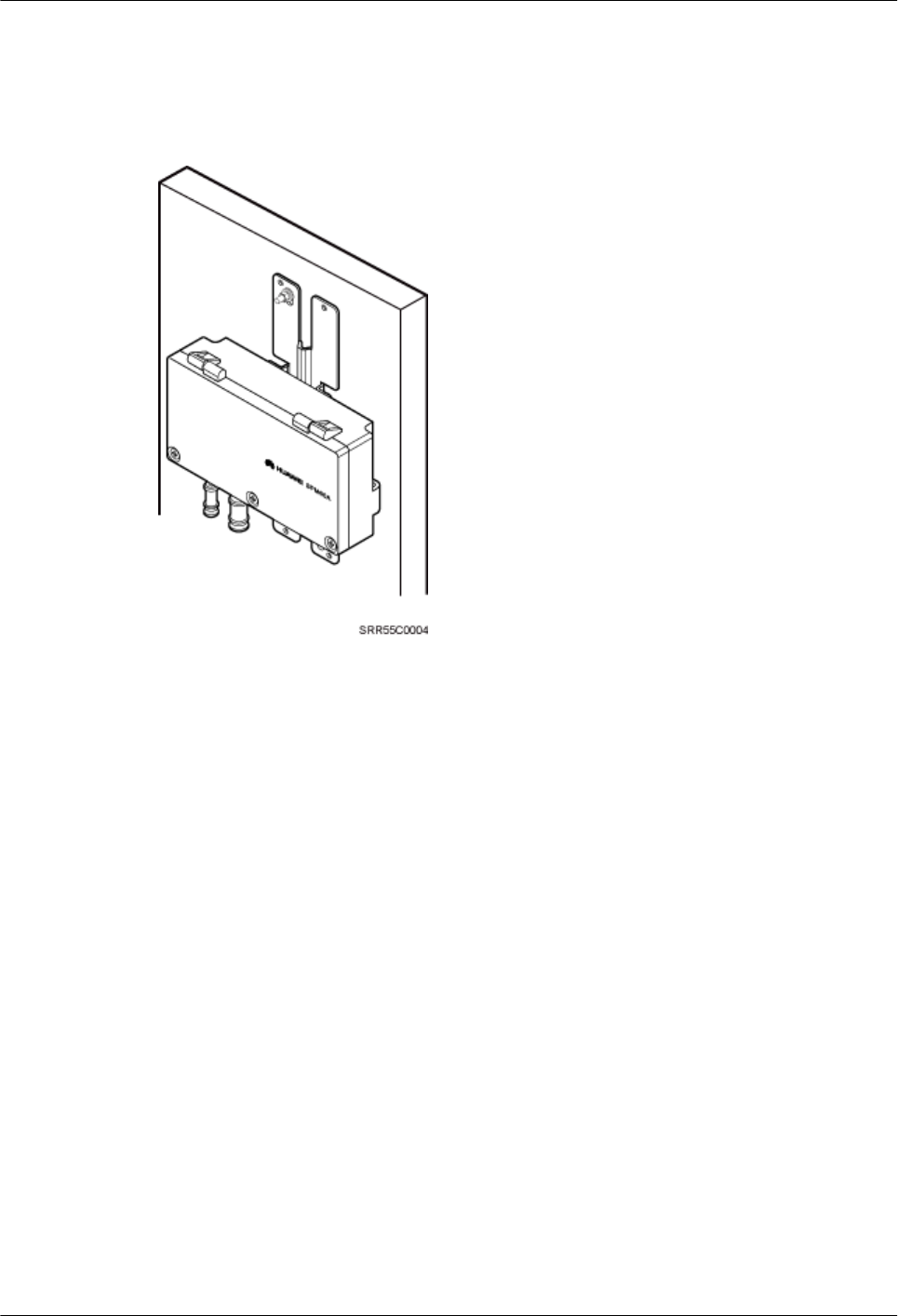
Installing an SPM60A on a Wall
Figure 9-27 shows an SPM60A installed on a wall.
Figure 9-27 An SPM60A installed on a wall
9.2.3 Installing an SPM60A
This section describes the procedure for installing an SPM60A.
Procedure
lInstalling an SPM60A on a Pole.
1. Loosen the screws on the hose clamp using an M6 hex torque screwdriver and open
the cover plate of SPM60A.
2. Put the hose clamp through the gap between the back cover plate and box body of
SPM60A and install the clamp holder.
3. Tighten the hose clamp and close the cover plate.
4. Tighten the screws on the hose clamp using an M6 hex torque screwdriver to 5 N m.
Figure 9-28 shows an SPM60A installed on a pole.
BTS3902E WCDMA
Installation Guide
9 (Optional) Installing the AC Surge Protection Box and
Cables
Issue 10 (2014-05-16) Huawei Proprietary and Confidential
Copyright © Huawei Technologies Co., Ltd.
115
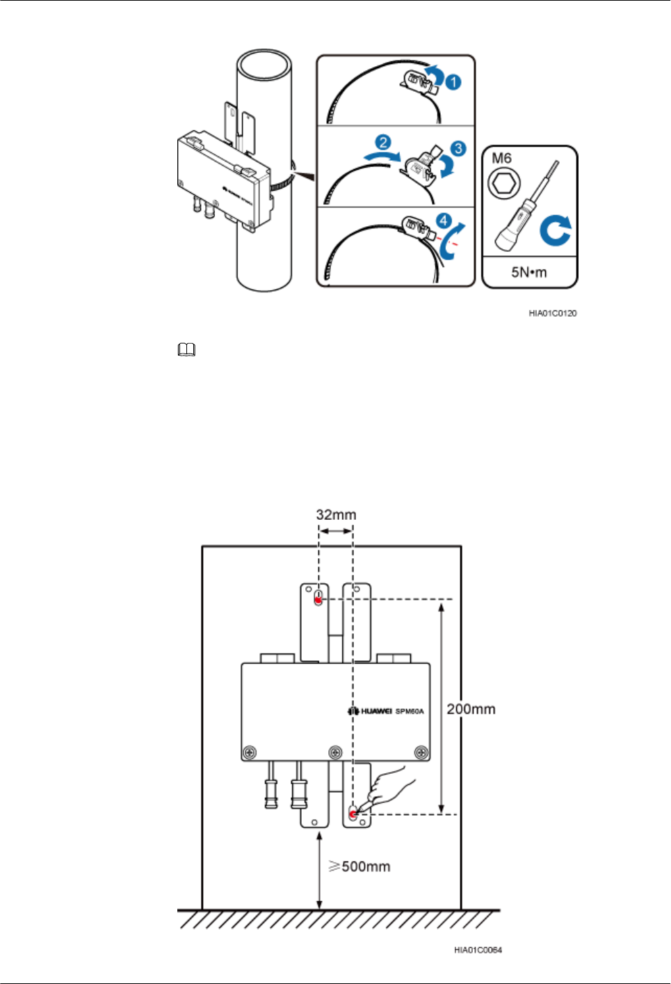
Figure 9-28 Installing SPM60A on a pole
NOTE
If the diameter of the pole is small, cut off the redundant part of the hose clamp.
lInstall an SPM60A on a wall.
1. The installation position on the wall has been determined. Press the back plate of the
SPM60A tightly on the wall, adjust and check the position using a level, and mark the
exact installation position using a marker, as shown in Figure 9-29.
Figure 9-29 Marking the installation position
BTS3902E WCDMA
Installation Guide
9 (Optional) Installing the AC Surge Protection Box and
Cables
Issue 10 (2014-05-16) Huawei Proprietary and Confidential
Copyright © Huawei Technologies Co., Ltd.
116
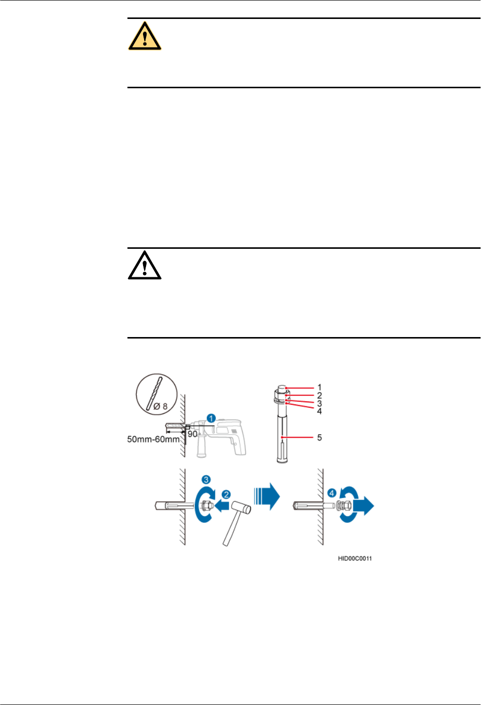
CAUTION
Operators need to take appropriate protective measures to prevent dust from being
taken into the respiratory tract or fallen into eyes.
2. Drill holes at the marked points and install expansion anchor bolts, as shown in Figure
9-30.
a. Drill holes vertically at the marked points on the wall using a hammer drill (φ 8
mm). The holes are 50 to 60 mm in depth.
b. Sightly tighten the expansion anchor bolt and put it into the hole.
c. Use a rubber mallet to knock the expansion anchor bolt until the expansion sleeve
is totally in the hole.
d. Tighten the expansion anchor bolt and then screw off the screw, spring washer,
and plain washer.
NOTICE
Disassemble the expansion anchor bolt and ensure that the upper surface of the
expansion sleeve is flush with the wall. Otherwise, the SPM60A is unsteady on the
wall.
Figure 9-30 Drilling and installing expansion anchor bolt
(1) M6 bolt (2) Nut (3) Spring washer (4) Plain washer (5) Expansion sleeve
3. Put the two bolts into the two holes on the SPM60A mounting kit, install the plain
washer, spring washer, and nut, and tighten the nut to 30 N m using the M6 torque
wrench with an opening of 10 mm, as shown in Figure 9-31.
BTS3902E WCDMA
Installation Guide
9 (Optional) Installing the AC Surge Protection Box and
Cables
Issue 10 (2014-05-16) Huawei Proprietary and Confidential
Copyright © Huawei Technologies Co., Ltd.
117
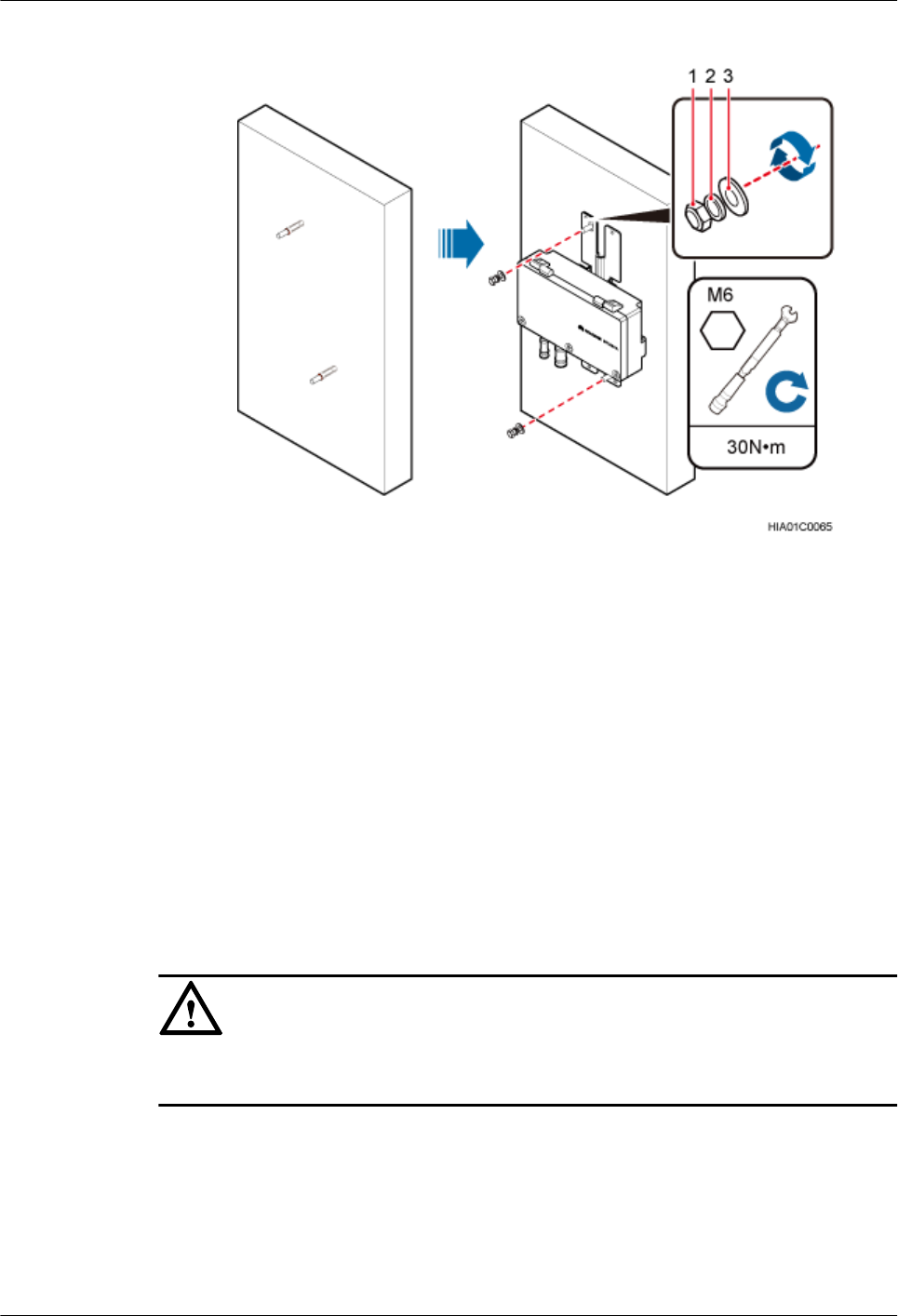
Figure 9-31 Installing an SPM60A on a wall
(1) Nut (2) Spring washer (3) Plain washer
----End
9.2.4 Installing Cables for an SPM60A
This section describes the procedure for installing cables for an SPM60A.
Prerequisites
Prepare OT terminals for connecting one end of a power cable to an SPM60A. For details, see
14.1.2 Preparing OT Terminals to the Power Cable Connected to the SPM60A .
Procedure
Step 1 Wear ESD gloves.
NOTICE
Take proper ESD protection measures, for example, wear ESD gloves, to prevent electrostatic
damage to the boards or electronic components.
Step 2 Use an M5 Phillips screwdriver to loosen the screws on the SPM60A and open the cover plate
to a 120° position, as shown in Figure 9-32.
BTS3902E WCDMA
Installation Guide
9 (Optional) Installing the AC Surge Protection Box and
Cables
Issue 10 (2014-05-16) Huawei Proprietary and Confidential
Copyright © Huawei Technologies Co., Ltd.
118
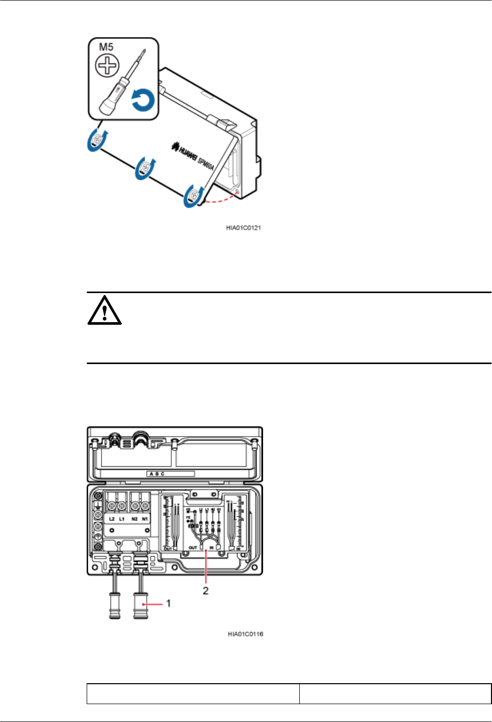
Figure 9-32 Opening the SPM60A cover plate
NOTICE
Open the cover plate slowly with care. When you feel the cover plate getting stuck, leave hold
of the cover plate carefully if the cover plate does not close.
Step 3 Take out the waterproof block from SPM60A, as shown in Figure 9-33.
Figure 9-33 Taking out the waterproof block
(1) Waterproof block (2) Surge protector
BTS3902E WCDMA
Installation Guide
9 (Optional) Installing the AC Surge Protection Box and
Cables
Issue 10 (2014-05-16) Huawei Proprietary and Confidential
Copyright © Huawei Technologies Co., Ltd.
119
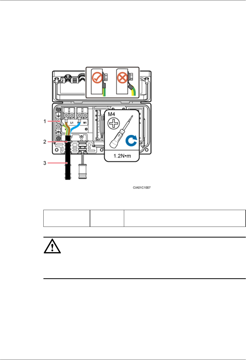
Step 4 Connect one end of the power cable to SPM60A and the other end to protected equipment. Put
the power cable between SPM60A and protected equipment through the OUT cable hole in the
SPM60A, and connect the brown wire with an OT terminal to the L2 terminal, the blue wire
with an OT terminal to the N2 terminal, and the yellow-green wire with an OT terminal to the
ground terminal. Use an M4 torque screwdriver to tighten the screws on the terminals to 1.4
N·m, as shown in Figure 9-34.
Figure 9-34 SPM60A connections
(1) Ground terminal (2) Cable hole (3) Power cable connecting an SPM60A and protected
equipment.
NOTICE
lArrange the internal cables. Bending OT terminals is not allowed.
lThe cable stripping length must be strictly in accordance with the cable diagram on labels.
Step 5 Put the power cable between the power equipment and SPM60A through the IN cable hole in
the SPM60A, and connect the brown wire with an OT terminal to the L1 terminal, the blue wire
with an OT terminal to the N1 terminal, and the yellow-green wire with an OT terminal to the
ground terminal. Use an M4 torque screwdriver to tighten the screws on the terminals to 1.2
N·m, as shown in Figure 9-35.
BTS3902E WCDMA
Installation Guide
9 (Optional) Installing the AC Surge Protection Box and
Cables
Issue 10 (2014-05-16) Huawei Proprietary and Confidential
Copyright © Huawei Technologies Co., Ltd.
120
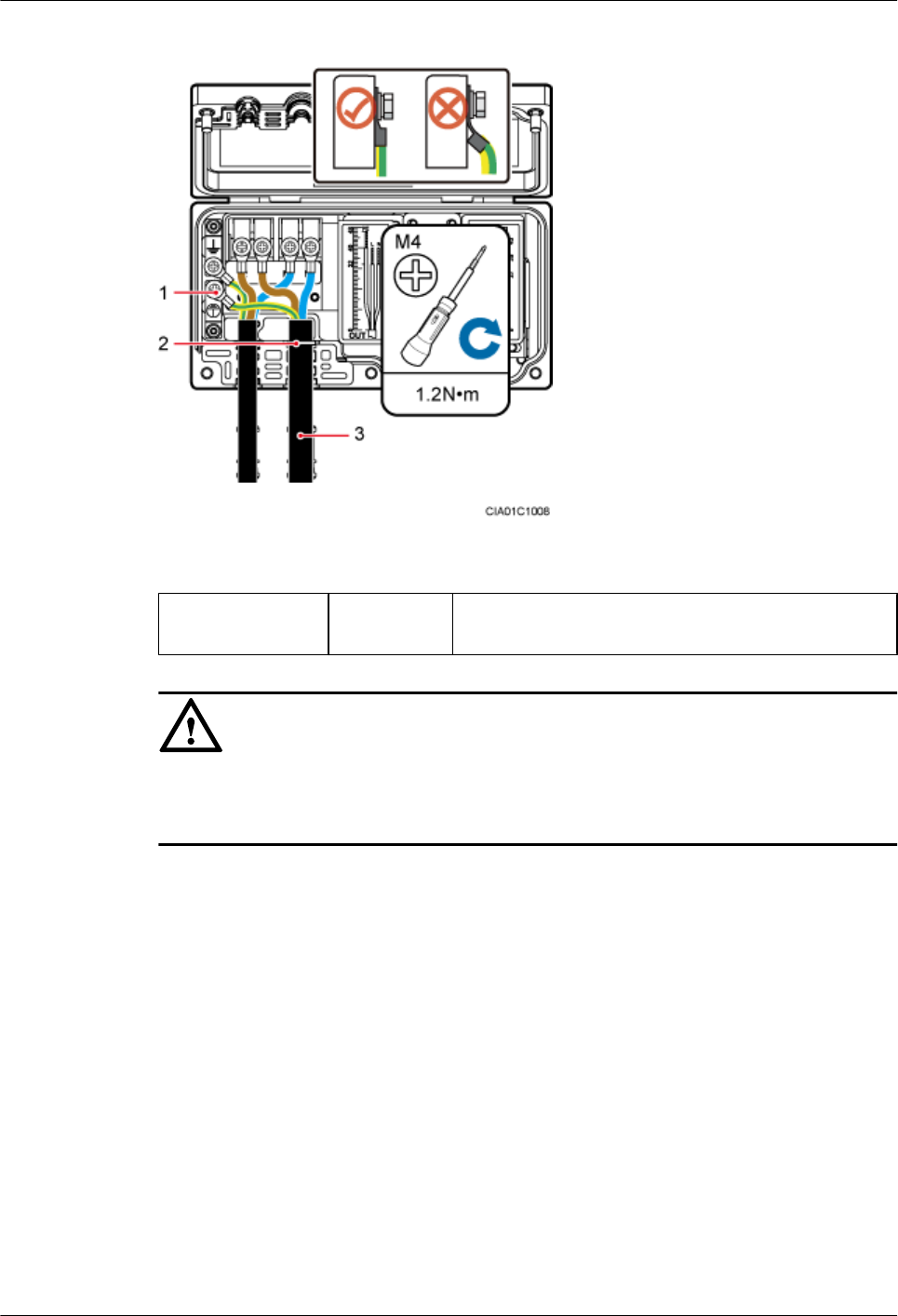
Figure 9-35 SPM60A connections
(1) Ground terminal (2) Cable hole (3) Power cable connecting the AC power equipment
and SPM60A
NOTICE
lArrange the internal cables. Bending OT terminals is not allowed.
lThe cable stripping length must be strictly in accordance with the cable diagram on labels.
Step 6 Use an M5 torque screwdriver to tighten the screws on the SPM60A cover plate to 2.0 N m and
close the cover plate, as shown in Figure 9-36.
BTS3902E WCDMA
Installation Guide
9 (Optional) Installing the AC Surge Protection Box and
Cables
Issue 10 (2014-05-16) Huawei Proprietary and Confidential
Copyright © Huawei Technologies Co., Ltd.
121
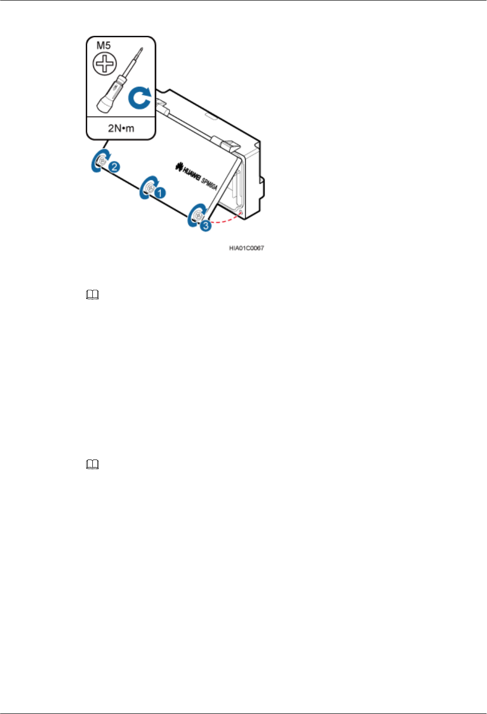
Figure 9-36 Closing the SPM60A cover plate
NOTE
All screws must be tightened for the second time.
Step 7 Wrap the waterproof tape and then the PVC insulation tape around both ends of each power
cable and around the connectors between corrugated pipes. Use two cable ties to bind the PVC
insulation tape at the position 3 mm to 5 mm away from both ends, as shown in Figure 9-37.
1. Wrap three-layer waterproof tape from bottom to top, from top to bottom, and then from
bottom to top again. Compact the tape and ensure that it is waterproof.
2. Wrap three-layer PVC insulation tape from bottom to top, from top to bottom, and then
from bottom to top again. Compact the tape and ensure that it is waterproof.
3. Use cable ties to bind the PVC insulation tape at the position 3 mm to 5 mm away from
both ends to prevent aging.
NOTE
lBefore wrapping waterproof tape, stretch the tape evenly until the length of the tape becomes twice its
original length.
lDo not stretch the PVC insulation tape when wrapping.
lWrap each layer of tape around the connector tightly and neatly, and ensure that each layer of tape overlaps
more than 50% of the preceding layer. Ensure that neighboring layers are stuck to each other.
lEnsure that the adhesive surface of the tape overlaps the preceding layer.
lWhen cutting off the cable ties, reserve a redundant length of 3 mm to 5 mm.
BTS3902E WCDMA
Installation Guide
9 (Optional) Installing the AC Surge Protection Box and
Cables
Issue 10 (2014-05-16) Huawei Proprietary and Confidential
Copyright © Huawei Technologies Co., Ltd.
122
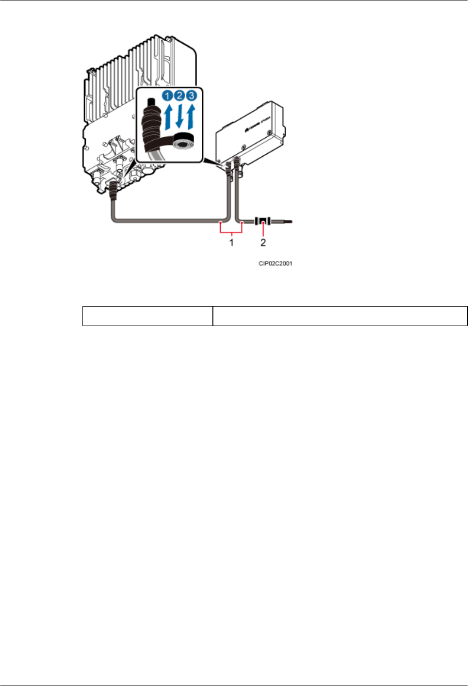
Figure 9-37 Securing power cables
(1) Corrugated pipe (2) Connector between corrugated pipes
Step 8 Use cable ties to bind the cables at equal spacing of 30 cm and verify that the bending radius of
the corrugated pipe is equal to or more than 60 mm.
Step 9 Laying Out Equipotential Cables and Protective Ground Cables, as shown in Figure 9-38.
BTS3902E WCDMA
Installation Guide
9 (Optional) Installing the AC Surge Protection Box and
Cables
Issue 10 (2014-05-16) Huawei Proprietary and Confidential
Copyright © Huawei Technologies Co., Ltd.
123
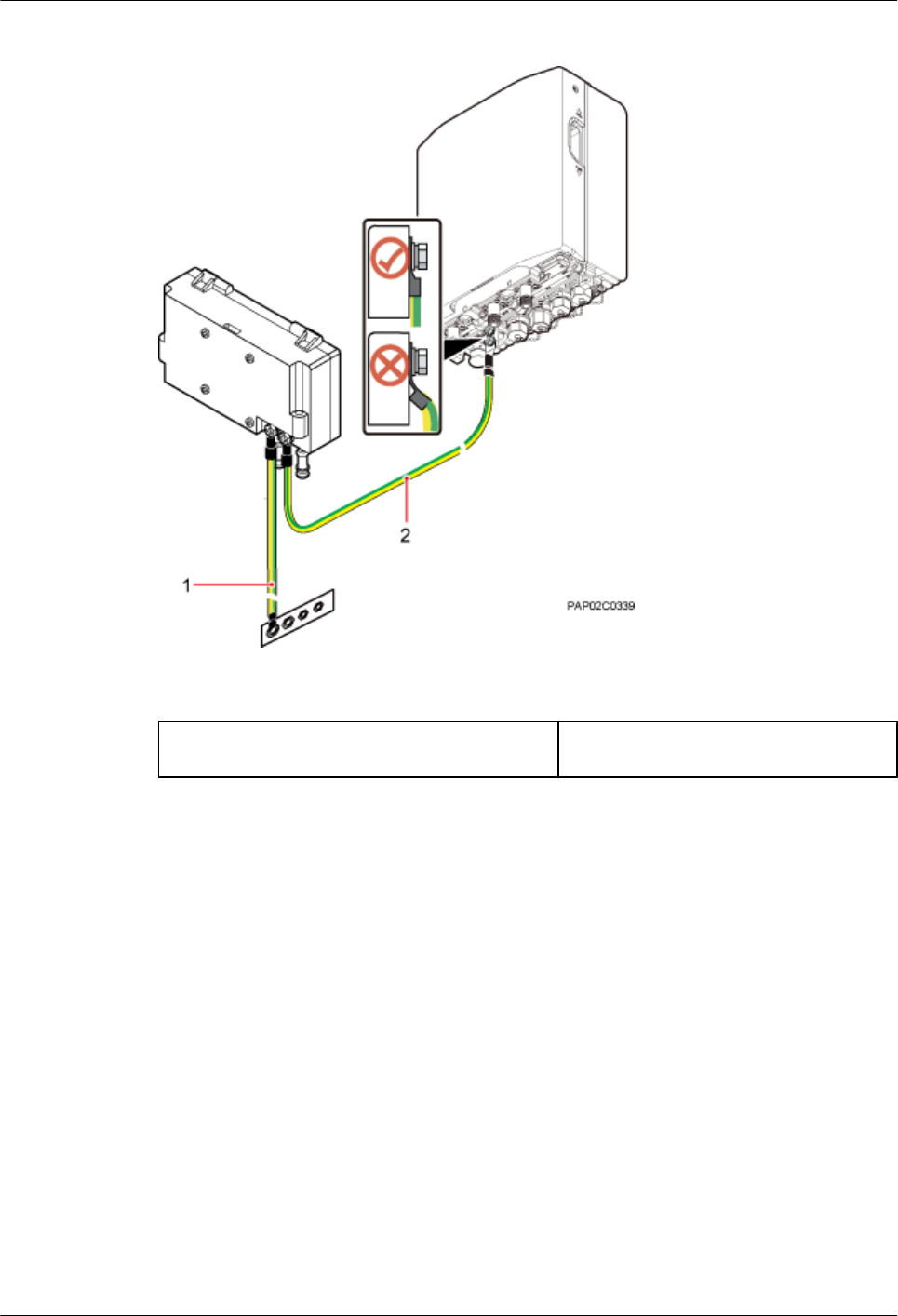
Figure 9-38 Laying Out Equipotential Cables and Protective Ground Cables
(1) Protective ground cable (2) Equipotential cable
Step 10 Lay out cables according to 10.1 Cabling Requirements and clamp the cables.
Step 11 Label the cables according to Attaching a Cable-Tying Label.
Step 12 Take off the ESD gloves, and pack up all the tools.
----End
BTS3902E WCDMA
Installation Guide
9 (Optional) Installing the AC Surge Protection Box and
Cables
Issue 10 (2014-05-16) Huawei Proprietary and Confidential
Copyright © Huawei Technologies Co., Ltd.
124

10 Installing Cables
About This Chapter
This chapter describes the procedures and precautions for installing the PGND cables, power
cables, and transmission cables for BTS3902Es installed in various scenarios. It also describes
the procedures and precautions for installing an optional alarm cable.
10.1 Cabling Requirements
Cables must be routed according to the specified cabling requirements to prevent signal
interference.
10.2 Cable Connections
The cable connections of the BTS3902E vary depending on the number of BTS3902Es and the
BTS3902E port.
10.3 Installing a PGND Cable and Equipotential Cable
The protection ground (PGND) cable and equipotential cable must be installed based on actual
requirements.
10.4 Installing a BTS3902E Power Cable
A BTS3902E power cable connects the BTS3902E to an external power device, feeding external
power into the BTS3902E.
10.5 Installing Transmission Cables
A fast Ethernet or gigabit Ethernet (FE/GE) cable or FE/GE fiber optic cable must be installed
for BTS3902Es as required.
10.6 (Optional) Installing a BTS3902E RF Jumper
You must install a radio frequency (RF) jumper when a BTS3902E uses an external antenna.
10.7 (Optional) Installing the Alarm Cable
This section describes the procedure for installing a BTS3902E alarm cable.
BTS3902E WCDMA
Installation Guide 10 Installing Cables
Issue 10 (2014-05-16) Huawei Proprietary and Confidential
Copyright © Huawei Technologies Co., Ltd.
125

10.1 Cabling Requirements
Cables must be routed according to the specified cabling requirements to prevent signal
interference.
NOTE
If a cable listed below is not required, skip the routing requirements of the cable.
General Cabling Requirements
The bending radius of the cables must meet the following specifications:
lThe bending radius of the 7/8'' feeder must be more than 250 mm (9.84 in.), and the bending
radius of the 5/4'' feeder must be more than 380 mm (14.96 in.).
lThe bending radius of the 1/4'' jumper must be more than 35 mm (1.38 in.). The bending
radius of the super-flexible 1/2'' jumper must be more than 50 mm (1.97 in.), and the bending
radius of the ordinary 1/2'' jumper must be more than 127 mm (5 in.).
lThe bending radius of the power cable or PGND cable must be at least three times the
diameter of the cable.
lThe bending radius of an fiber optic cable is at least 20 times the diameter of the fiber optic
cable.
lThe bending radius of the signal cable must be at least five times the diameter of the cable.
The cables must be bound as follows:
lThe cables must be bound tightly and neatly. The sheaths of the cables must not be damaged.
lThe cable ties must face the same direction, and those at the same horizontal line must be
in a straight line. Extra length of cable ties must be cut.
lLabels or nameplates must be attached to the cables after they are installed.
The cables must be routed as follows:
lDifferent types of cables must be installed in an untangled and orderly fashion.
lDifferent types of cables must be routed in parallel or separated by special objects.
Special Cabling Requirements
Cabling requirements for power cables are as follows:
lMultiple power cables must be bound when routed.
lPower cables must be installed in the position specified in engineering design documents.
lIf the length of power cables is insufficient, replace the cables rather than adding connectors
or soldering joints to lengthen the cables.
Cabling Requirements for PGND Cables are as follows:
lPGND cables for the base station must be connected to the same ground bar.
lPGND cables must be buried in the ground or routed indoors. They should not be routed
overhead before they are led into the equipment room.
BTS3902E WCDMA
Installation Guide 10 Installing Cables
Issue 10 (2014-05-16) Huawei Proprietary and Confidential
Copyright © Huawei Technologies Co., Ltd.
126

lThe exterior of the coaxial wire and the shield layer of the shielded cable must have proper
electrical contact with the metal surface of the equipment to which they are connected.
lPGND cables and signal cables must be installed in an untangled and orderly fashion. A
certain distance must be reserved between them to prevent interference from each other.
lFuses or switches must not be installed on the PGND cables.
lOther devices must not be used for electrical connections of the PGND cables.
lAll the metal parts in the housing of the equipment must be reliably connected to the ground
terminal.
Cabling Requirements for E1 Cables are as follows:
lE1 cables must not cross power cables, PGND cables, or RF cables when routed. If
transmission cables are routed with power cables, PGND cables, or RF cables in parallel,
the spacing between them must be greater than 30 mm (1.18 in.).
lE1 cables are routed straightly and bound neatly with cable ties.
lSufficient slack is provided in E1 cables at turns.
Cabling Requirements for Fiber Optic Cables are as follows:
lFiber optic cables must be routed by at least three qualified and trained personnel before
all preparations are made.
lFiber optic cables are used within the temperature range of -40°C to +60°C. If the current
temperature is out of the range, make protection measures or route the cables again.
lCables are routed in an untangled and orderly fashion.
lDo not bind fiber optic cables at turns.
lDo not stretch, step on, or place heavy objects on fiber optic cables. Keep the cables away
from sharp objects.
lWhen fiber optic cables are routed, the excess of the cables must be coiled around special
devices, such as a fiber coiler.
lWhen coiling fiber optic cables, apply even strength. Do not bend the cables with force.
lVacant optical connectors must be covered with dustproof caps.
lFiber optic cables cannot be squeezed by the cabinet door when routed through the cabinet.
lIf fiber optic cables need to be routed on the tower platform, lay out the cables on the
guardrail with the shortest distance and route the cables along the guardrail.
lIf fiber optic cables need to be routed close to a device on the tower, secure the cables to
the guardrail or pole with cable clips. The device cannot be far away from the position for
securing the cables.
lIf the fiber optic cables close to a device are too long, coil the excess of the cables and
secure them on the tower.
10.2 Cable Connections
The cable connections of the BTS3902E vary depending on the number of BTS3902Es and the
BTS3902E port.
The cable connections are similar when the BTS3902E uses AC power supply (working at the
1.9 GHz, 2.1 GHz or 850 MHz frequency band) or uses DC power supply (working at the AWS
frequency band). The differences are as follows:
BTS3902E WCDMA
Installation Guide 10 Installing Cables
Issue 10 (2014-05-16) Huawei Proprietary and Confidential
Copyright © Huawei Technologies Co., Ltd.
127
lThe outdoor BTS3902E using AC power supply (working at the 1.9 GHz or 2.1 GHz
frequency band) can be configured with the SPD60D and related cables.
lThe outdoor BTS3902E using AC power supply (working at the 850 MHz frequency band)
can be configured with the SPM60A and related cables.
lFor the BTS3902E using DC power supply (working at the AWS frequency band), the AC
surge protection box and related cables are not required.
The following section describes the cable connections for the BTS3902E with AC power supply
(working at the 1.9 GHz or 2.1 GHz frequency band).
Four typical transmission solutions can apply to the BTS3902E, as shown in Table 10-1.
Table 10-1 Typical transmission solutions
Scenario Typical Transmission
Solution
Description
Single
BTS3902E
Wired transmission Figure 10-1 shows the cable connections.
Wireless transmission Figure 10-2 shows the cable connections.
Two
cascaded
BTS3902Es
Wired transmission Figure 10-3 and Figure 10-4 show the cable
connections.
Wireless transmission Figure 10-5 shows the cable connections.
NOTE
lA BTS3902E can connect to the transmission network over an electrical port or optical port, depending
on actual requirements. However, one BTS3902E can use two transmission ports at most, one for
connection to the transmission network, and the other for cascading.
lThe OPT1 and ETH ports cannot be both enabled for the same BTS3902E.
Single BTS3902E Using Wired Transmission
Figure 10-1 shows the cable connections for a single BTS3902E that uses wired transmission.
BTS3902E WCDMA
Installation Guide 10 Installing Cables
Issue 10 (2014-05-16) Huawei Proprietary and Confidential
Copyright © Huawei Technologies Co., Ltd.
128
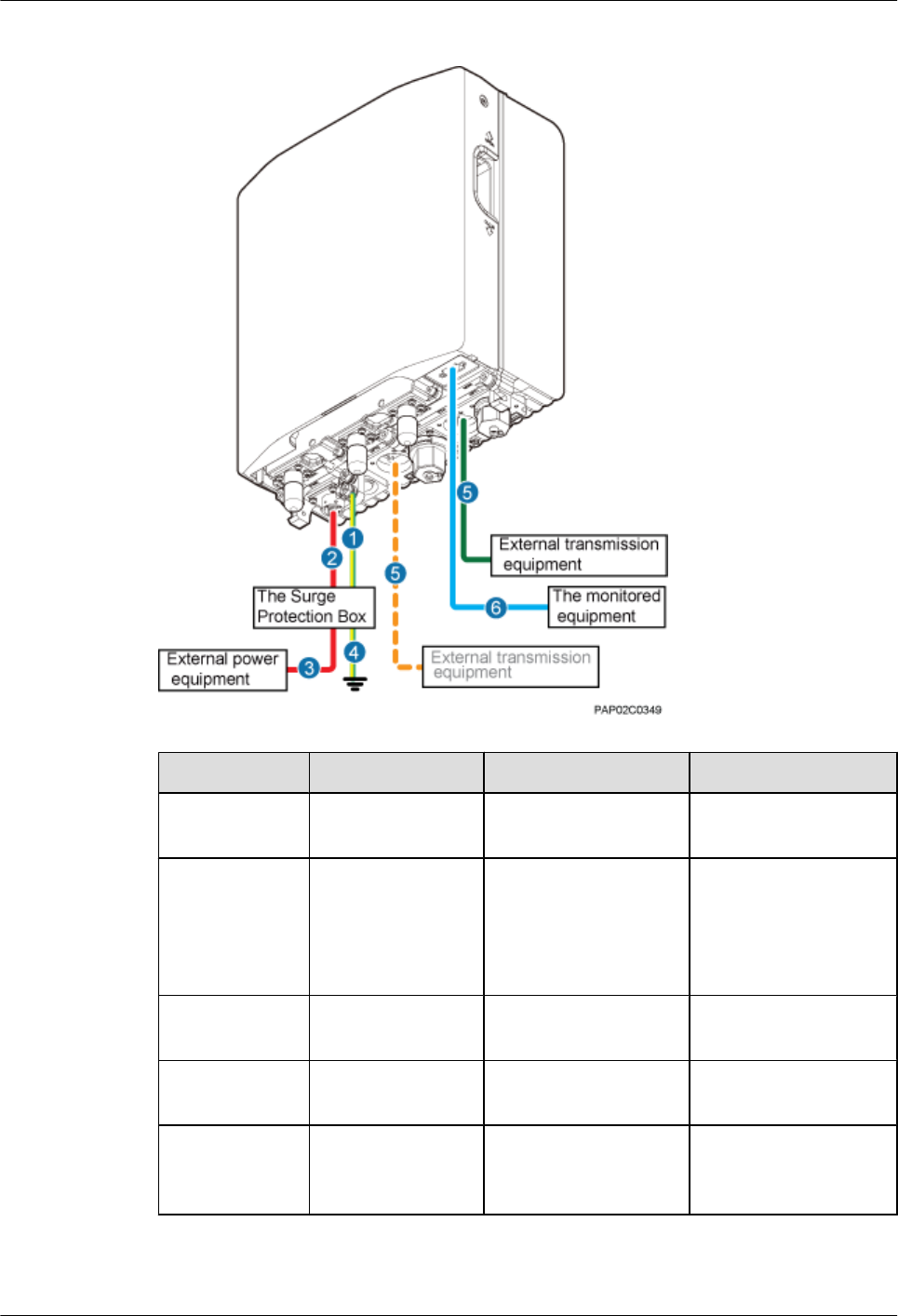
Figure 10-1 Cable connections for a single BTS3902E using wired transmission
No. Cable One End The Other End
(1) Equipotential cable Ground terminal of the
BTS3902E
AC surge protection box
(2) Power cable
between the
BTS3902E and the
surge protection
box
The PWR port on the
BTS3902E
AC surge protection box
(3) BTS3902E power
cable
AC surge protection
box
External power supply
system
(4) PGND cable AC surge protection
box
External PGND bar/
ground terminal
(5) FE/GE cable The ETH port on the
BTS3902E
Network port on the
external transmission
equipment
BTS3902E WCDMA
Installation Guide 10 Installing Cables
Issue 10 (2014-05-16) Huawei Proprietary and Confidential
Copyright © Huawei Technologies Co., Ltd.
129
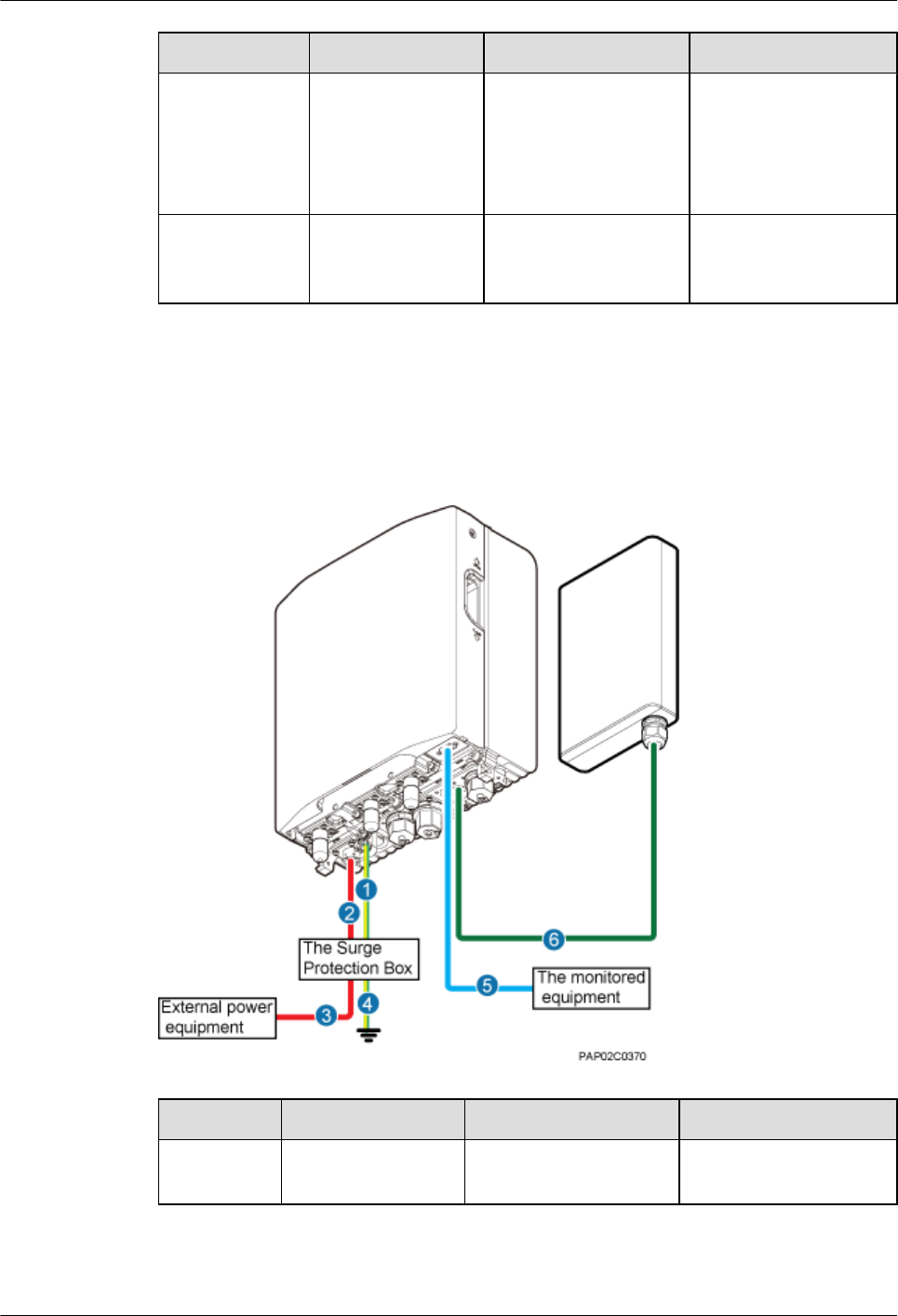
No. Cable One End The Other End
NOTE
Either an FE/GE
cable or an FE/
GE fiber optic
cable can be
used.
FE/GE fiber optic
cable
The OPT0 or OPT1 port
on the BTS3902E
Optical port on the
external transmission
equipment
(6) (Optional)
BTS3902E alarm
cable
The MON port on the
BTS3902E
External monitored
equipment
Single BTS3902E Using Wireless Transmission
Figure 10-2 shows the cable connections for a single BTS3902E that uses wireless transmission.
Figure 10-2 Cable connections for a single BTS3902E using wireless transmission
No. Cable One End The Other End
(1) Equipotential cable Ground terminal of the
BTS3902E
AC surge protection box
BTS3902E WCDMA
Installation Guide 10 Installing Cables
Issue 10 (2014-05-16) Huawei Proprietary and Confidential
Copyright © Huawei Technologies Co., Ltd.
130
No. Cable One End The Other End
(2) Power cable between
the BTS3902E and
the surge protection
box
The PWR port on the
BTS3902E
AC surge protection box
(3) BTS3902E power
cable
AC surge protection box External power supply
system
(4) PGND cable AC surge protection box External PGND bar/
ground terminal
(5) (Optional)
BTS3902E alarm
cable
The MON port on the
BTS3902E
External monitored
equipment
(6) FE/GE cable The ETH port on the
BTS3902E
Wireless transmission
equipment
Two Cascaded BTS3902Es Using Wired Transmission
Figure 10-3, Figure 10-4 shows the cable connections for two BTS3902Es that use wired
transmission.
BTS3902E WCDMA
Installation Guide 10 Installing Cables
Issue 10 (2014-05-16) Huawei Proprietary and Confidential
Copyright © Huawei Technologies Co., Ltd.
131
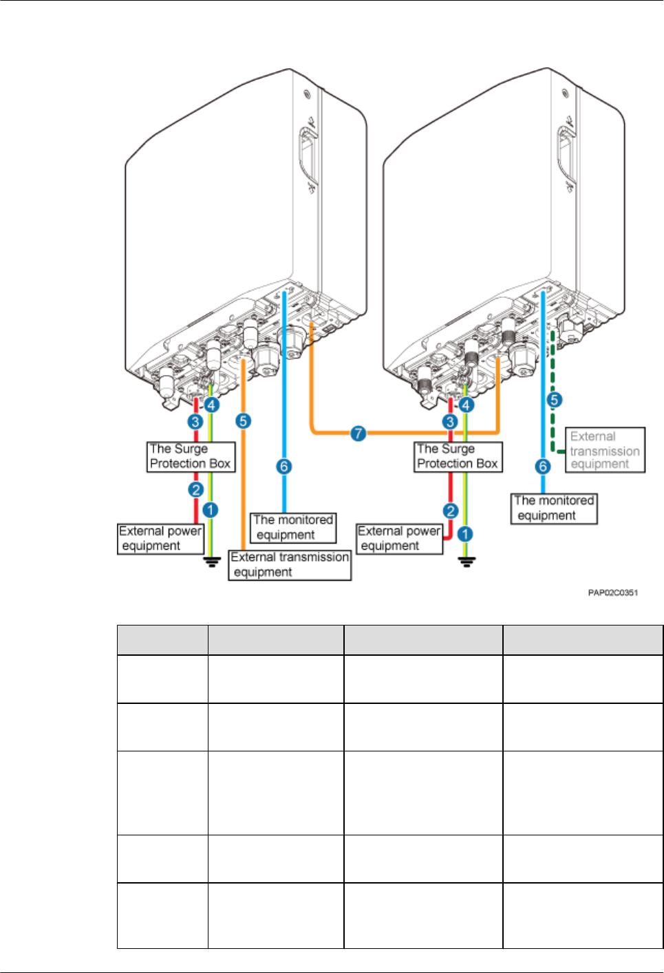
Figure 10-3 Cable connections for two BTS3902Es cascaded using a fiber optic cable in wired
transmission
No. Cable One End The Other End
(1) PGND cable AC surge protection box External PGND bar/
ground terminal
(2) BTS3902E power
cable
AC surge protection box External power supply
system
(3) Power cable between
the BTS3902E and
the surge protection
box
The PWR port on the
BTS3902E
AC surge protection box
(4) Equipotential cable Ground terminal of the
BTS3902E
AC surge protection box
(5) FE/GE cable The ETH port on the
BTS3902E
Network port on the
external transmission
equipment
BTS3902E WCDMA
Installation Guide 10 Installing Cables
Issue 10 (2014-05-16) Huawei Proprietary and Confidential
Copyright © Huawei Technologies Co., Ltd.
132
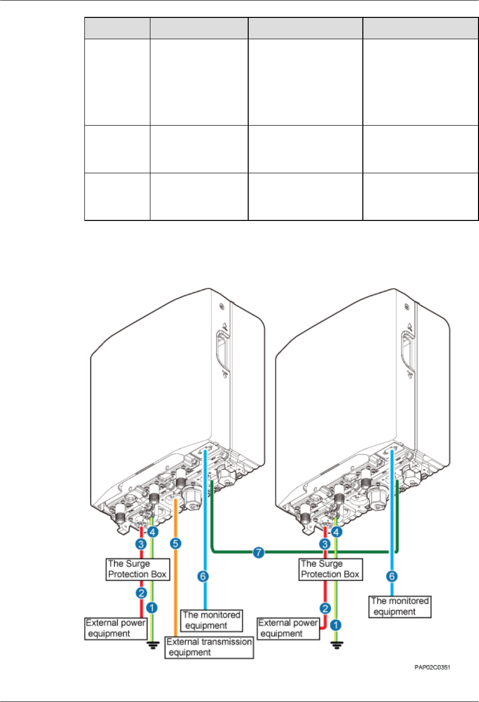
No. Cable One End The Other End
NOTE
Either an FE/
GE cable or
an FE/GE
fiber optic
cable can be
used.
FE/GE fiber optic
cable
The OPT0 or OPT1 port
on the BTS3902E
Optical port on the
external transmission
equipment
(6) (Optional)
BTS3902E alarm
cable
The MON port on the
BTS3902E
External monitored
equipment
(7) cascading FE/GE
fiber optic cable
The OPT0 or OPT1 port
on the BTS3902E
The OPT0 or OPT1 port
on the lower-level
cascaded BTS3902E
Figure 10-4 Cable connections for two BTS3902Es cascaded using an FE/GE cable in wired
transmission
BTS3902E WCDMA
Installation Guide 10 Installing Cables
Issue 10 (2014-05-16) Huawei Proprietary and Confidential
Copyright © Huawei Technologies Co., Ltd.
133
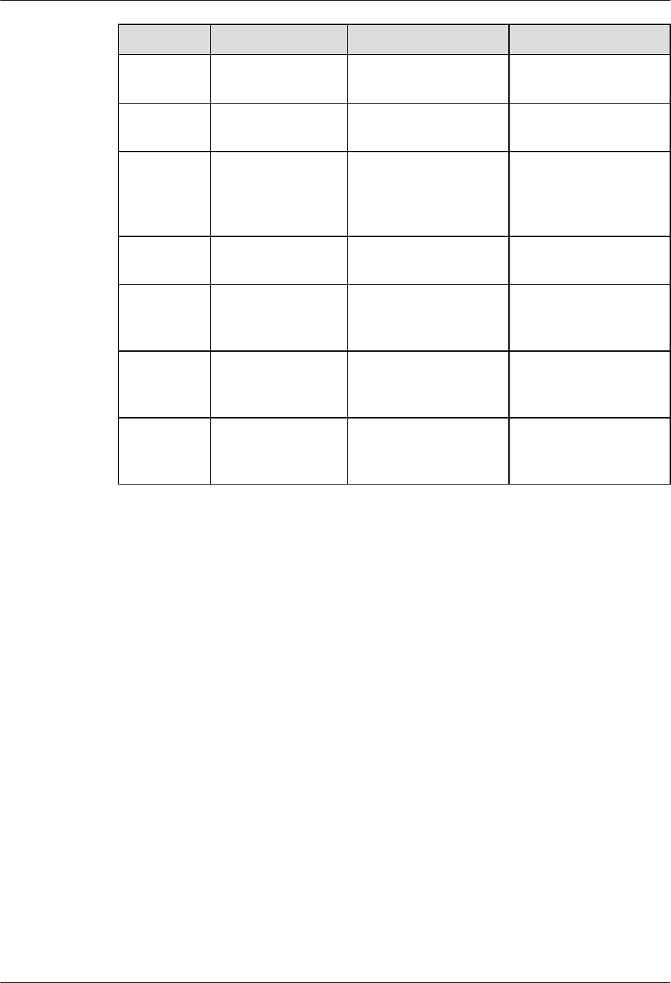
No. Cable One End The Other End
(1) PGND cable AC surge protection box External PGND bar/
ground terminal
(2) BTS3902E power
cable
AC surge protection box External power supply
system
(3) Power cable between
the BTS3902E and
the surge protection
box
The PWR port on the
BTS3902E
AC surge protection box
(4) Equipotential cable Ground terminal of the
BTS3902E
AC surge protection box
(5) FE/GE fiber optic
cable
The OPT0 or OPT1 port
on the BTS3902E
Optical port on the
external transmission
equipment
(6) (Optional)
BTS3902E alarm
cable
The MON port on the
BTS3902E
External monitored
equipment
(7) cascading FE/GE
cable
The ETH port on the
BTS3902E
The ETH port on the
lower-level cascaded
BTS3902E
Two Cascaded BTS3902Es Using Wireless Transmission
Figure 10-5 shows the cable connections for two BTS3902Es that use wireless transmission.
BTS3902E WCDMA
Installation Guide 10 Installing Cables
Issue 10 (2014-05-16) Huawei Proprietary and Confidential
Copyright © Huawei Technologies Co., Ltd.
134
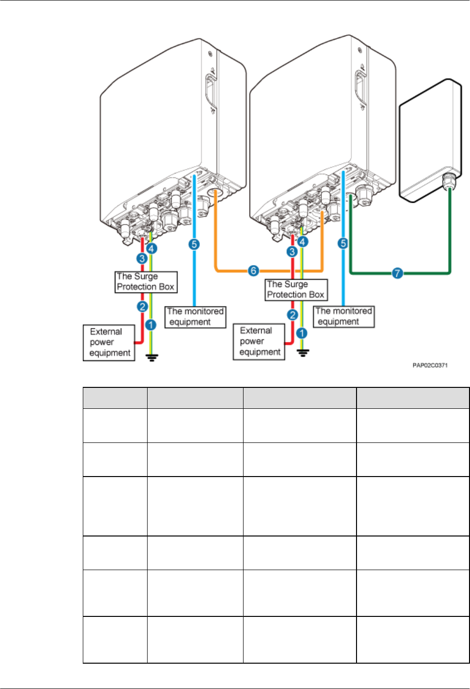
Figure 10-5 Cable connections for two BTS3902Es using wireless transmission
No. Cable One End The Other End
(1) PGND cable AC surge protection box External PGND bar/
ground terminal
(2) BTS3902E power
cable
AC surge protection box External power supply
system
(3) Power cable between
the BTS3902E and
the surge protection
box
The PWR port on the
BTS3902E
AC surge protection box
(4) Equipotential cable Ground terminal of the
BTS3902E
AC surge protection box
(5) (Optional)
BTS3902E alarm
cable
The MON port on the
BTS3902E
External monitored
equipment
(6) Cascading FE/GE
fiber optic cable
The OPT0 or OPT1 port
on the BTS3902E
The OPT0 port on the
lower-level cascaded
BTS3902E
BTS3902E WCDMA
Installation Guide 10 Installing Cables
Issue 10 (2014-05-16) Huawei Proprietary and Confidential
Copyright © Huawei Technologies Co., Ltd.
135
No. Cable One End The Other End
(7) FE/GE cable The ETH port on the
lower-level cascaded
BTS3902E
Wireless transmission
equipment
10.3 Installing a PGND Cable and Equipotential Cable
The protection ground (PGND) cable and equipotential cable must be installed based on actual
requirements.
Context
When an AC surge protection box (which is optional) is configured for a BTS3902E, two PGND
cables are required. One provides equipotential connection between the AC surge protection
box and the BTS3902E, and the other connects the AC surge protection box and a ground bar
to ensure proper grounding of the AC surge protection box.
Table 10-2, Table 10-3 lists the specifications of the PGND cable and equipotential cable.
Table 10-2 Specifications of the BTS3902E PGND cable and equipotential cable (working at
the 1.9 GHz, 2.1 GHz or AWS frequency band)
Cable One End The Other End Remarks
PGND cable OT terminal (M6, 16
mm2)
OT terminal (M6, 16
mm2)
Green and yellow
Equipotential cable OT terminal (M6, 16
mm2)
OT terminal (M6, 16
mm2)
Green and yellow
Table 10-3 Specifications of the BTS3902E PGND cable and equipotential cable (working at
the 850 GHz frequency band)
Cable One End The Other End Remarks
PGND cable OT terminal (M6, 6
mm2)
OT terminal (M6, 6
mm2)
Green and yellow
Equipotential cable OT terminal (M6, 6
mm2)
OT terminal (M6, 6
mm2)
Green and yellow
NOTE
The cable route depends on actual requirements.
BTS3902E WCDMA
Installation Guide 10 Installing Cables
Issue 10 (2014-05-16) Huawei Proprietary and Confidential
Copyright © Huawei Technologies Co., Ltd.
136
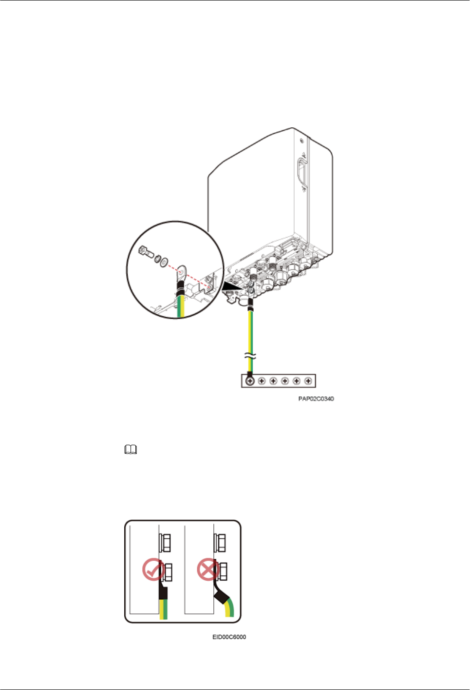
Procedure
lInstall a PGND cable if no AC surge protection box is installed, as shown in Figure
10-6.
1. Connect one end of the BTS3902E PGND cable to the ground terminal on the
BTS3902E and the other end to the external ground bar.
Figure 10-6 Installing the BTS3902E PGND cable
NOTE
When installing the PGND cable, tightly press the OT terminal in the correct direction, as
shown in Figure 10-7.
Figure 10-7 Installing an OT terminal in the correct manner
BTS3902E WCDMA
Installation Guide 10 Installing Cables
Issue 10 (2014-05-16) Huawei Proprietary and Confidential
Copyright © Huawei Technologies Co., Ltd.
137
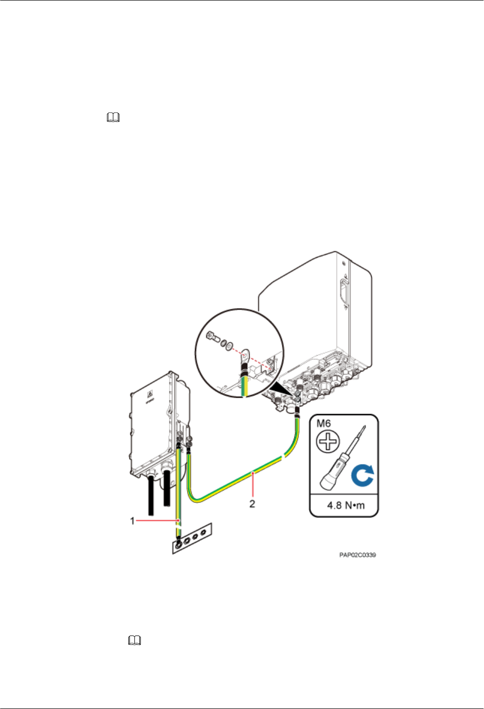
2. Route the cable by referring to 10.1 Cabling Requirements, and then use cable ties
to bind the cable.
3. Label the installed cable by referring to Attaching a Cable-Tying Label in Installation
Reference.
lInstall a PGND cable and equipotential cable if an AC surge protection box is installed, as
shown in Figure 10-8.
NOTE
There are two types of the AC surge protection box (SPD60D and SPM60A), for which the installing
procedure is the same. The following part uses SPD60D as an example to describe.
1. Connect one end of the BTS3902E equipotential cable to the ground terminal on the
BTS3902E and the other end to the AC surge protection box (SPB).
2. Connect one end of the BTS3902E PGND cable to the ground terminal on the AC
PDB and the other end to the external ground bar.
Figure 10-8 Installing a PGND cable and equipotential cable
(1) PGND cable (2) Equipotential cable
NOTE
When installing the PGND cable, tightly press the OT terminal in the correct direction, as
shown in Figure 10-9.
BTS3902E WCDMA
Installation Guide 10 Installing Cables
Issue 10 (2014-05-16) Huawei Proprietary and Confidential
Copyright © Huawei Technologies Co., Ltd.
138
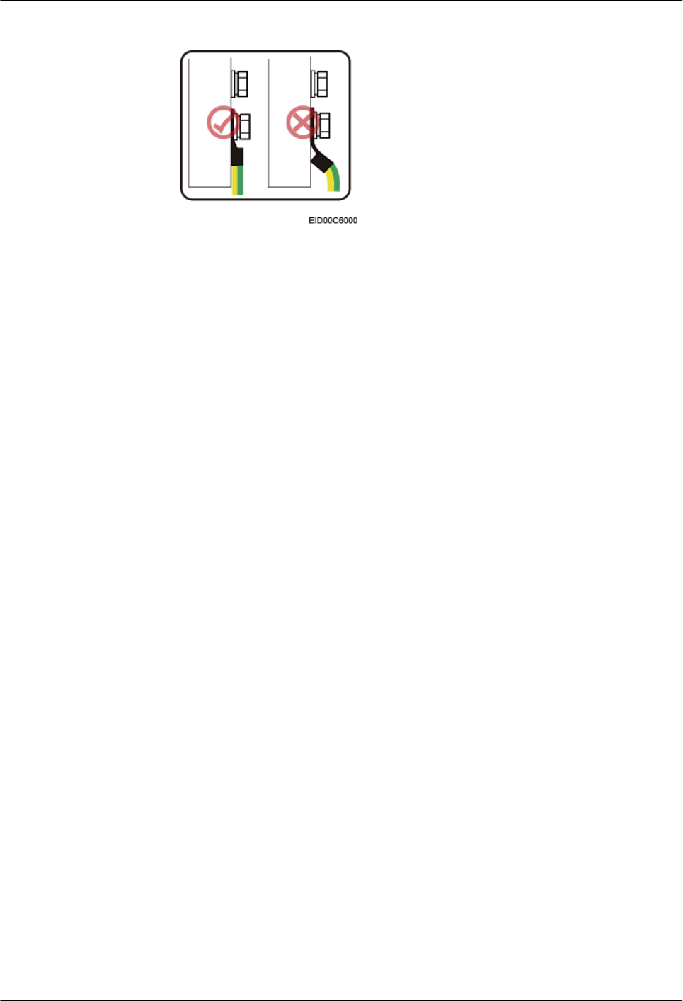
Figure 10-9 Installing an OT terminal in the correct manner
3. Route the cable by referring to 10.1 Cabling Requirements, and then use cable ties
to bind the cable.
4. Label the installed cable by referring to Attaching a Cable-Tying Label in Installation
Reference.
lInstall a PGND cable if BTS3902Es are installed on an IFS06, as shown in Figure 10-10.
1. Connect one end of the BTS3902E PGND cable to the ground terminal on the
BTS3902E and the other end to the ground terminal of the ground bar on the IFS06.
BTS3902E WCDMA
Installation Guide 10 Installing Cables
Issue 10 (2014-05-16) Huawei Proprietary and Confidential
Copyright © Huawei Technologies Co., Ltd.
139
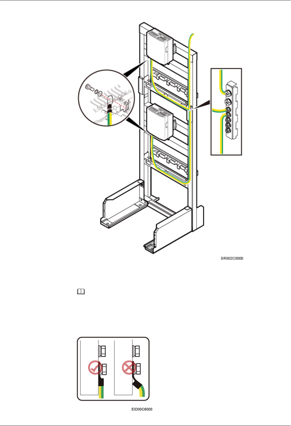
Figure 10-10 Installing a PGND cable
NOTE
When installing the PGND cable, tightly press the OT terminal in the correct direction, as
shown in Figure 10-11.
Figure 10-11 Installing an OT terminal in the correct manner
BTS3902E WCDMA
Installation Guide 10 Installing Cables
Issue 10 (2014-05-16) Huawei Proprietary and Confidential
Copyright © Huawei Technologies Co., Ltd.
140
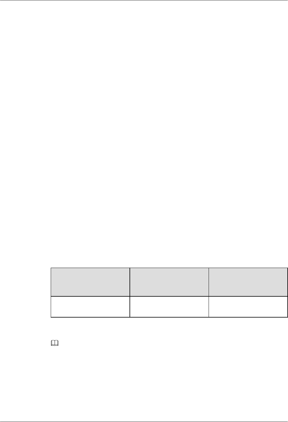
2. Route the cable by referring to 10.1 Cabling Requirements, and then use cable ties
to bind the cable.
3. Label the installed cable by referring to Attaching a Cable-Tying Label in Installation
Reference.
----End
10.4 Installing a BTS3902E Power Cable
A BTS3902E power cable connects the BTS3902E to an external power device, feeding external
power into the BTS3902E.
10.4.1 Installing an AC Power Cable (Working at the 1.9 GHz, 2.1
GHz or 850 MHz Frequency Band)
This section applies only to the BTS3902E that uses AC power supply.
Prerequisites
lThe tools, such as a Phillips screwdriver, a cable cutter, and a power cable crimping tool,
are ready.
lThe PGND cable and equipotential cable are installed.
Context
Table 10-4 lists the recommended configurations of upper-level circuit breakers and power
cables for a BTS3902E.
Table 10-4 Recommended configurations of upper-level circuit breakers and power cables for
a BTS3902E
Input Power Requirement for the
Circuit Breakers on
Customer Equipment
Cross-sectional Area of
an Input Power Cable
220 V/110 V AC single-
phase
5 A/1 P(1) 1.5 mm2
NOTE
(1) P is short for Pole, indicating the number of switches simultaneously controlled by a pole.
Table 10-5, Table 10-6 lists the specifications of the BTS3902E power cable.
BTS3902E WCDMA
Installation Guide 10 Installing Cables
Issue 10 (2014-05-16) Huawei Proprietary and Confidential
Copyright © Huawei Technologies Co., Ltd.
141
Table 10-5 Specifications of the BTS3902E power cable (working at the 1.9 GHz or 2.1 GHz
frequency band)
Cable One End The Other End Remarks
BTS3902E power cable 3-pin waterproofed round
AC connector (1.5 mm2)
Depending on the
external equipment
Black
Power cable between
the BTS3902E and the
AC surge protection box
3-pin waterproofed round
AC connector (1.5 mm2)
OT terminal (M4, 1.5
mm2)
Black
Power cable between
the surge protection box
and the external power
equipment
OT terminal (M4, 4 mm2)Depending on the
external equipment
Black
Table 10-6 Specifications of the BTS3902E power cable (working at the 850 MHz frequency
band)
Cable One End The Other End Remarks
BTS3902E power cable 3-pin waterproofed round
AC connector (1.5 mm2)
Depending on the
external equipment
Black
Power cable between
the BTS3902E and the
AC surge protection box
3-pin waterproofed round
AC connector (1.5 mm2)
OT terminal (M4, 1.5
mm2)
Black
Power cable between
the surge protection box
and the external power
equipment
OT terminal (M4, 2.5
mm2)
Depending on the
external equipment
Black
NOTE
The cable route depends on actual requirements.
Procedure
lInstall the BTS3902E power cable in the AC power supply scenario when no AC surge
protection box is configured, as shown in Figure 10-12.
1. Link the 3-pin waterproofed round AC connector at one end of the BTS3902E power
cable to the PWR port on the BTS3902E, and tighten the connector.
2. Connect the other end to external power equipment.
BTS3902E WCDMA
Installation Guide 10 Installing Cables
Issue 10 (2014-05-16) Huawei Proprietary and Confidential
Copyright © Huawei Technologies Co., Ltd.
142
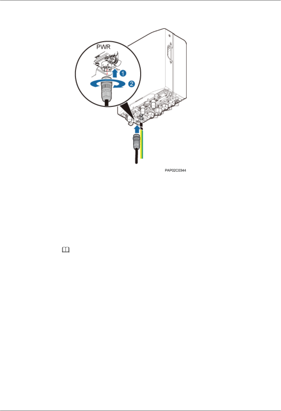
Figure 10-12 Connection of the power cable between the BTS3902E and power
equipment
3. Route the cable by referring to 10.1 Cabling Requirements, and then use cable ties
to bind the cable.
4. Label the installed cable by referring to Attaching a Cable-Tying Label in Installation
Reference.
lInstall the BTS3902E power cable in the AC power supply scenario when an AC surge
protection box is configured, as shown in Figure 10-13.
NOTE
There are two types of the AC surge protection box (SPD60D and SPM60A), for which the installing
procedure is the same. The following part uses SPD60D as an example to describe.
1. Link the 3-pin waterproofed round AC connector at one end of the power cable
between the BTS3902E and the surge protection box to the PWR port on the
BTS3902E, and tighten the connector.
2. Connect the other end to the surge protection box
BTS3902E WCDMA
Installation Guide 10 Installing Cables
Issue 10 (2014-05-16) Huawei Proprietary and Confidential
Copyright © Huawei Technologies Co., Ltd.
143
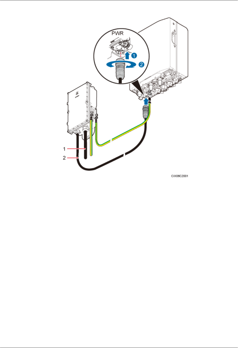
Figure 10-13 Connection of the BTS3902E power cable to the surge protection box
(1) Power cable between the surge protection box
and external power equipment
(2) Power cable between the BTS3902E and the
surge protection box
3. Connect one end of the power cable between the surge protection box and external
power equipment to the surge protection box and the other end to external power
equipment by referring to 9.1.4 Installing Cables for an SPD60D or 9.2.4 Installing
Cables for an SPM60A.
4. Route the cable by referring to 10.1 Cabling Requirements, and then use cable ties
to bind the cable.
5. Label the installed cable by referring to Attaching a Cable-Tying Label in Installation
Reference.
----End
10.4.2 Installing a DC Power Cable (Working at the AWS Frequency
Band)
This section applies only to the BTS3902E that uses DC power supply.
BTS3902E WCDMA
Installation Guide 10 Installing Cables
Issue 10 (2014-05-16) Huawei Proprietary and Confidential
Copyright © Huawei Technologies Co., Ltd.
144
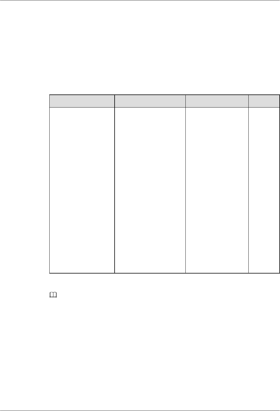
Prerequisites
lThe following tools are available: a Phillips screwdriver, a cable cutter, and a power cable
crimping tool.
lA PGND cable and an equipotential cable have been installed.
Context
Table 10-7 lists the BTS3902E power cable specifications.
Table 10-7 BTS3902E power cable specifications
Cable One End The Other End Remarks
BTS3902E power cable Waterproofed round DC
connector
Depending on the
external equipment
There are
two types
of power
cables in
terms of
cross-
sectional
areas: 3.3
mm2 (12
AWG)
complyin
g with
North
American
standards
and 4
mm2
complyin
g with
European
standards.
NOTE
The cable route depends on actual requirements.
Procedure
Step 1 Prepare a power cable.
1. Cut the cable to a length suitable for the actual cable route.
2. Install a waterproofed round DC connector onto the power cable on the BTS3902E side by
referring to 14.2 Adding a Waterproofed Round DC Connector to the BTS3902E
Power Cable on the BTS3902E Side.
Step 2 Connect the 2-pin waterproofed round DC connector at one end of the BTS3902E power cable
to the PWR port on the BTS3902E. Push the 2-pin waterproofed round DC connector upwards
until it snaps into place.
BTS3902E WCDMA
Installation Guide 10 Installing Cables
Issue 10 (2014-05-16) Huawei Proprietary and Confidential
Copyright © Huawei Technologies Co., Ltd.
145
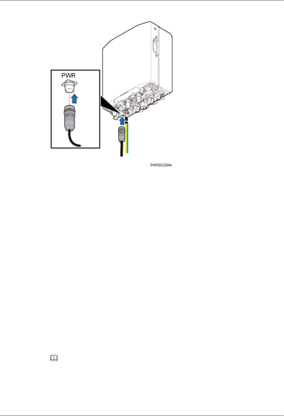
Figure 10-14 Installing a BTS3902E power cable
Step 3 Connect the other end of the BTS3902E power cable to external power equipment.
Step 4 Route the cable according to the instructions in 10.1 Cabling Requirements, and then use a
cable tie to bind the cable.
Step 5 Label the cable by referring to Attaching a Cable-Tying Label.
----End
10.5 Installing Transmission Cables
A fast Ethernet or gigabit Ethernet (FE/GE) cable or FE/GE fiber optic cable must be installed
for BTS3902Es as required.
10.5.1 Installing an FE/GE Cable
This section describes the procedure and precautions for installing a fast Ethernet or gigabit
Ethernet (FE/GE).
Context
NOTE
The cable route depends on actual requirements.
Procedure
Step 1 Remove the waterproof cap from the ETH port on the BTS3902E.
BTS3902E WCDMA
Installation Guide 10 Installing Cables
Issue 10 (2014-05-16) Huawei Proprietary and Confidential
Copyright © Huawei Technologies Co., Ltd.
146
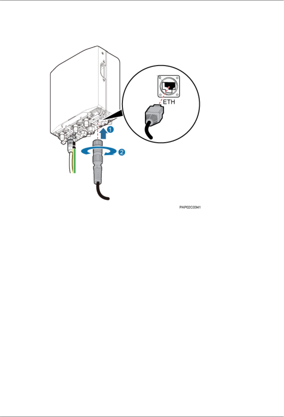
Step 2 Connect one end of the FE/GE cable to the ETH port on the BTS3902E, and tighten the round
connector until it snaps shut, as shown in Figure 10-15.
Figure 10-15 Installing the FE/GE cable
Step 3 Install a ground clip on the FE/GE cable by referring to 14.3 Installing a Ground Clip.
Step 4 Route the cable by referring to 10.1 Cabling Requirements, and then use cable ties to bind the
cable.
Step 5 Label the installed cable by referring to Attaching a Sign Plate Label in Installation Reference.
----End
10.5.2 Installing an FE/GE Fiber Optic Cable
This section describes the procedure and precautions for installing a fast Ethernet or gigabit
Ethernet (FE/GE) fiber optic cable with DLC connector.
Context
lThe single-mode optical module to be installed must match the rate at the optical port.
lDo not twist, bend, stretch, or extrude fibers during installation.
BTS3902E WCDMA
Installation Guide 10 Installing Cables
Issue 10 (2014-05-16) Huawei Proprietary and Confidential
Copyright © Huawei Technologies Co., Ltd.
147
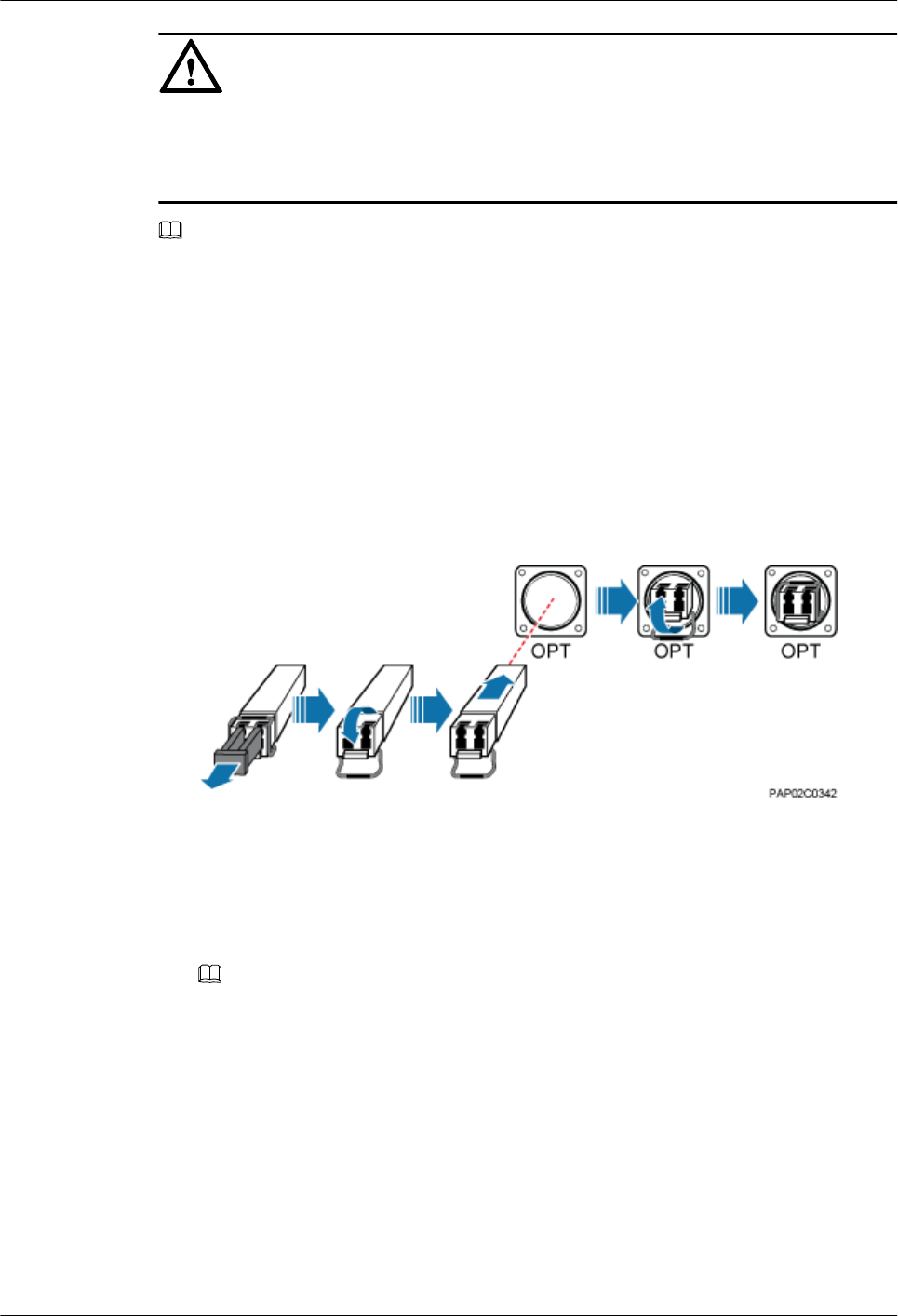
NOTICE
The performance of an optical module that is exposed to the air for more than 20 minutes may
be abnormal. Therefore, you must insert an fiber optic cable into an unpacked optical module
within 20 minutes.
NOTE
The cable route depends on actual requirements.
Procedure
Step 1 Remove the waterproof cap from the OPT0 port on the BTS3902E.
Step 2 Install the optical module.
1. Remove the dustproof cap of the optical module and store it properly for future use.
2. Turn the puller of an optical module outwards and insert the optical module into the
OPT0 port on the BTS3902E, as shown in Figure 10-16.
Figure 10-16 Installing the optical module
Step 3 Install the FE/GE fiber optic cable.
1. Open the protective cap from the round connector, take out the optical fibers, cut the traction
cables, as shown in Figure 10-17.
NOTE
Please store the dustproof cap of the optical fiber connector properly for future use.
BTS3902E WCDMA
Installation Guide 10 Installing Cables
Issue 10 (2014-05-16) Huawei Proprietary and Confidential
Copyright © Huawei Technologies Co., Ltd.
148
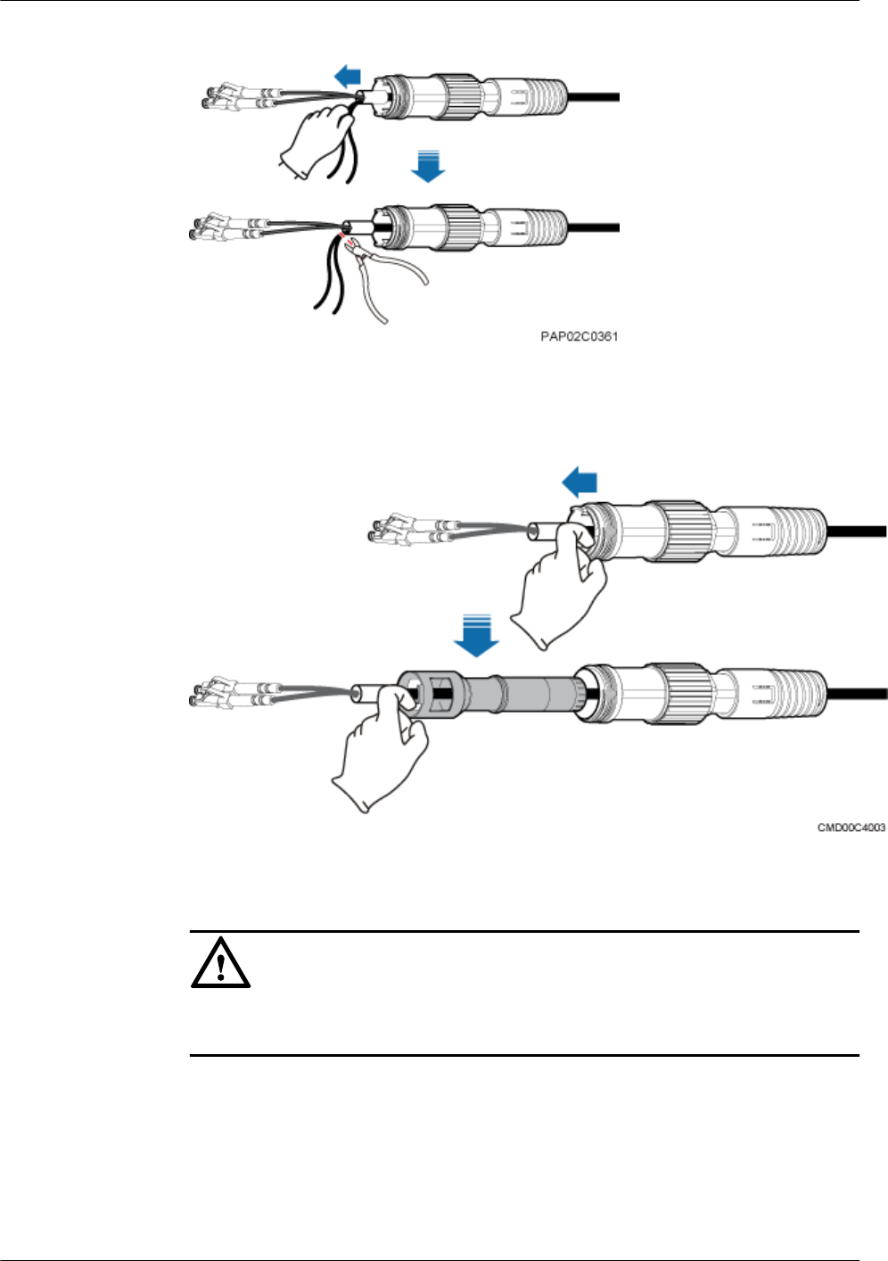
Figure 10-17 Taking out the optical fiber connector
2. Separate the inner gasket from outer gasket of the round connector, as shown in Figure
10-18.
Figure 10-18 Separating the inner gasket from outer gasket
3. Sort the optical fibers, remove the dustproof cap from the optical fiber connector, and insert
the DLC connector into the optical module.
NOTICE
To keep the surface of round connector clean, do not remove the dustproof cap before
inserting the DLC connector into the optical module.
4. Align the clamping jaw on the inner gasket with the socket of the OPT0 port on the
BTS3902E. Insert and fit the clamping jaw into the socket. Hold the optical fiber at the end
of the DLC connector and pull the fiber optic cable straight in the round connector to avoid
twist of the optical fibers, as shown in Figure 10-19.
BTS3902E WCDMA
Installation Guide 10 Installing Cables
Issue 10 (2014-05-16) Huawei Proprietary and Confidential
Copyright © Huawei Technologies Co., Ltd.
149
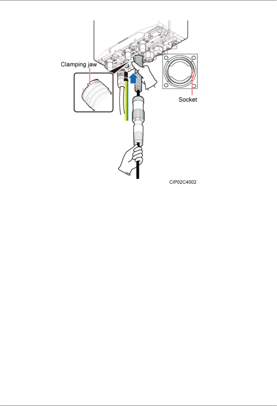
Figure 10-19 Installing the inner gasket of the round connector
5. Push the outer socket of the round connector upwards and tighten the outer socket, as shown
in Figure 10-20.
BTS3902E WCDMA
Installation Guide 10 Installing Cables
Issue 10 (2014-05-16) Huawei Proprietary and Confidential
Copyright © Huawei Technologies Co., Ltd.
150
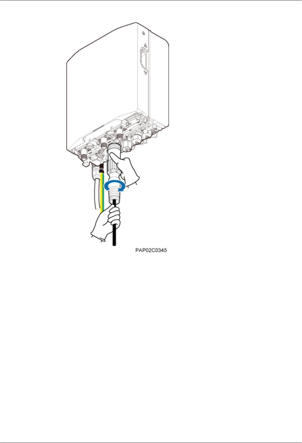
Figure 10-20 Installing the outer gasket of the round connector
Step 4 Route the cable by referring to 10.1 Cabling Requirements, and then use cable ties to bind the
cable.
Step 5 Label the installed cable by referring to Attaching a Sign Plate Label in Installation Reference.
----End
10.5.3 Installing a Cascading FE/GE Fiber Optic Cable
When multiple BTS3902Es implement transmission over FE/GE optical ports, the BTS3902Es
are interconnected using a cascading FE/GE fiber optic cable.
Context
The single-mode optical module to be installed must match the rate at the optical port.
BTS3902E WCDMA
Installation Guide 10 Installing Cables
Issue 10 (2014-05-16) Huawei Proprietary and Confidential
Copyright © Huawei Technologies Co., Ltd.
151
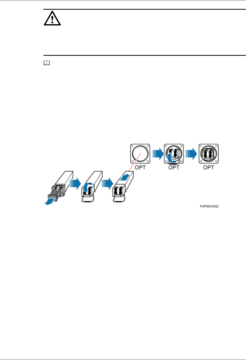
NOTICE
The performance of an optical module that is exposed to the air for more than 20 minutes may
be abnormal. Therefore, you must insert an fiber optic cable into an unpacked optical module
within 20 minutes.
NOTE
The cable route depends on actual requirements.
Procedure
Step 1 Remove the waterproof caps from the OPT0 or OPT1 port on the BTS3902E A and OPT0 or
OPT1 port on the BTS3902E B.
Step 2 Turn the puller of each optical module outwards and insert the optical module into the OPT0 or
OPT1 port on each BTS3902E, as shown in Figure 10-21.
Figure 10-21 Installing an optical module
Step 3 Connect the two ends of the cascading FE/GE fiber optic cable to the OPT0 or OPT1 port on
the BTS3902E A and OPT0 or OPT1 port on the BTS3902E B, respectively, and then tighten
the round connector until the connector snaps shut, as shown in Figure 10-22.
BTS3902E WCDMA
Installation Guide 10 Installing Cables
Issue 10 (2014-05-16) Huawei Proprietary and Confidential
Copyright © Huawei Technologies Co., Ltd.
152
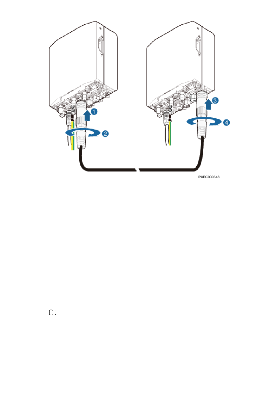
Figure 10-22 Installing the cascading FE/GE fiber optic cable
Step 4 Route the cable by referring to 10.1 Cabling Requirements, and then use cable ties to bind the
cable.
Step 5 Label the installed cable by referring to Attaching a Sign Plate Label in Installation Reference.
----End
10.5.4 Installing a Cascading FE/GE Cable
When multiple BTS3902Es implement transmission over FE/GE electrical ports, the
BTS3902Es are interconnected using a cascading FE/GE cable.
Context
NOTE
The cable route depends on actual requirements.
Procedure
Step 1 Remove the waterproof caps from the ETH port on the BTS3902E A and ETH port on the
BTS3902E B.
Step 2 Connect the two ends of the cascading FE/GE cable to the ETH port on the BTS3902E A and
ETH port on the BTS3902E B, and tighten the round connector until it snaps shut, as shown in
Figure 10-23.
BTS3902E WCDMA
Installation Guide 10 Installing Cables
Issue 10 (2014-05-16) Huawei Proprietary and Confidential
Copyright © Huawei Technologies Co., Ltd.
153
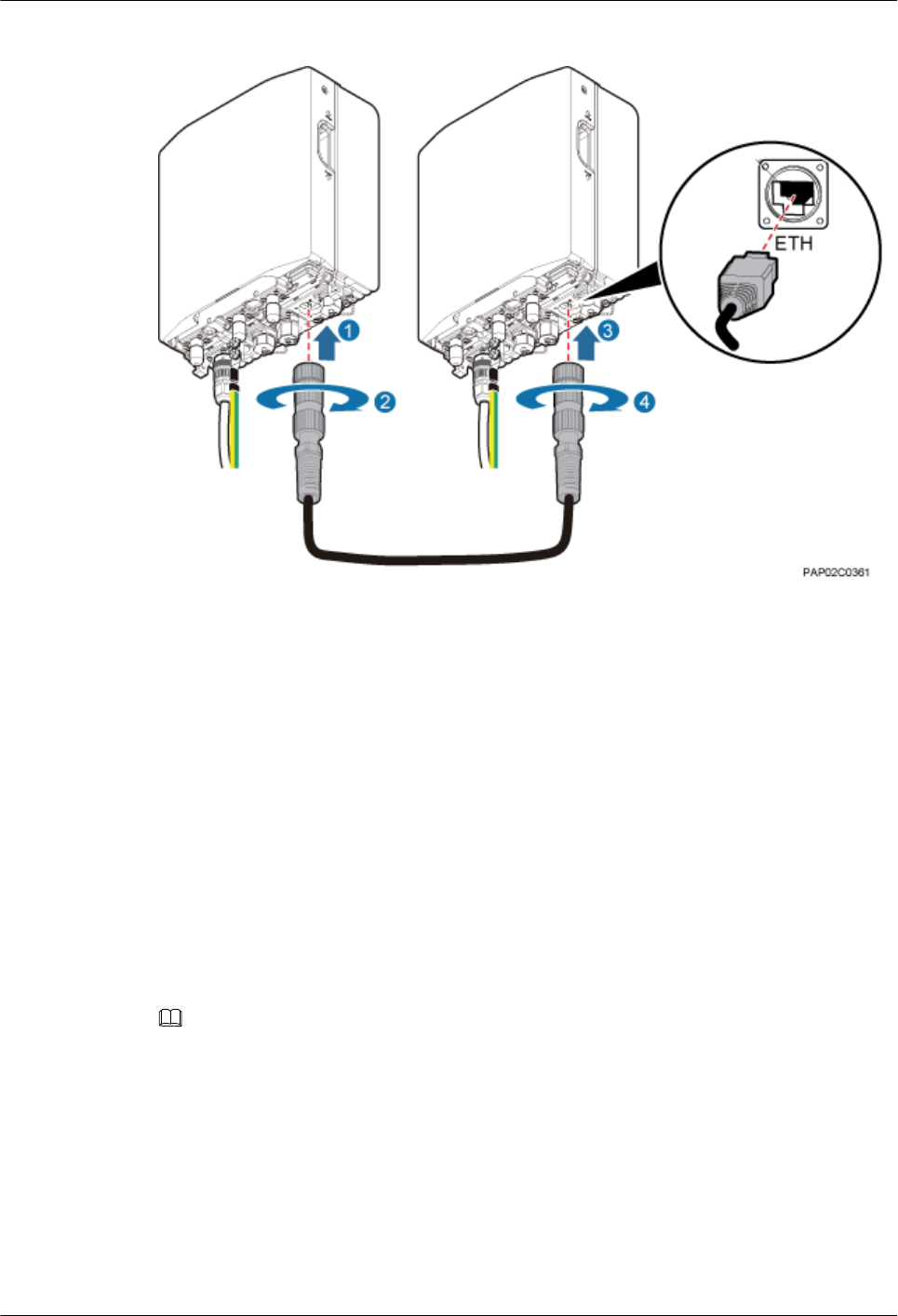
Figure 10-23 Installing the cascading FE/GE cable
Step 3 Install a ground clip on the FE/GE cable by referring to 14.3 Installing a Ground Clip.
Step 4 Route the cable by referring to 10.1 Cabling Requirements, and then use cable ties to bind the
cable.
Step 5 Label the installed cable by referring to Attaching a Sign Plate Label in Installation Reference.
----End
10.6 (Optional) Installing a BTS3902E RF Jumper
You must install a radio frequency (RF) jumper when a BTS3902E uses an external antenna.
Context
NOTE
The cable route depends on actual requirements.
Procedure
Step 1 Link the type N male connector at one end of the BTS3902E RF jumper to the ANT port, and
connect the other end to an external antenna system, as shown in Figure 10-24.
BTS3902E WCDMA
Installation Guide 10 Installing Cables
Issue 10 (2014-05-16) Huawei Proprietary and Confidential
Copyright © Huawei Technologies Co., Ltd.
154
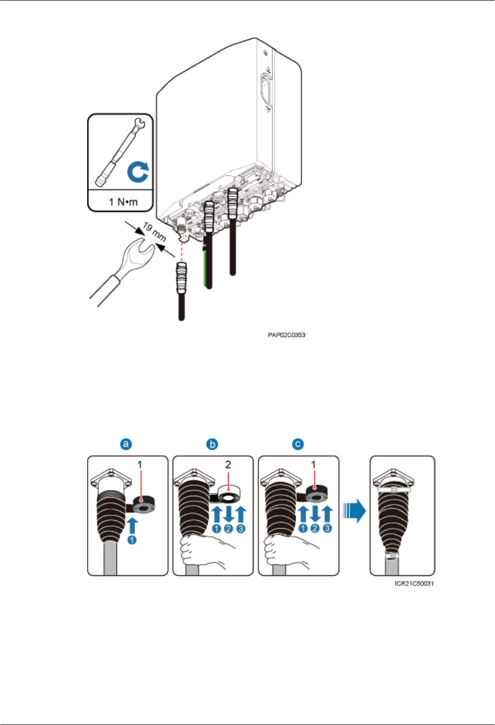
Figure 10-24 Installing the BTS3902E RF jumper
Step 2 Wrap the connector of the BTS3902E RF jumper using tape, as shown in Figure 10-25.
Figure 10-25 Wrap the connector of the BTS3902E RF jumper
(1) PVC insulation tape (2) Waterproof tape
1. Wrap a layer of PVC insulation tape around the connector from bottom up.
2. Tightly wrap three layers of waterproof tape around the connector, with the first layer from
bottom up, the second layer from top down, and the third layer from bottom up.
BTS3902E WCDMA
Installation Guide 10 Installing Cables
Issue 10 (2014-05-16) Huawei Proprietary and Confidential
Copyright © Huawei Technologies Co., Ltd.
155
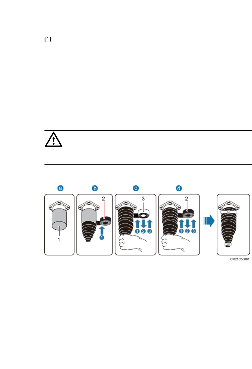
3. Tightly wrap three layers of PVC insulation tape around the connector with the first layer
from bottom up, the second layer from top down, and the third layer from bottom up.
4. Bundle cable ties 3 mm (0.12 in.) to 5 mm (0.20 in.) away from the end of insulating tape.
NOTE
lBefore wrapping waterproof tape, stretch the tape evenly until the length of the tape is twice its original
length.
lDo not stretch the PVC insulation tape before wrapping.
lWrap each layer of tape around the connector tightly and neatly, and ensure that each layer of tape overlaps
more than 50% of the preceding layer
lEnsure that the side with adhesive tape is covered on the wrapped tape.
lWhen cutting off the cable tie, reserve a surplus length of 3 mm (0.12 in.) to 5 mm (0.20 in.).
Step 3 Check the dustproof caps on the antenna connectors. In outdoor scenarios, dustproof caps must
be wrapped with tape, as shown in Figure 10-26.
NOTICE
Do not remove dustproof caps from vacant antenna connectors.
Figure 10-26 Waterproofing a dustproof cap
(1) Dustproof cap (2) PVC insulation tape (3) Waterproof tape
1. Verify that dustproof caps are not removed.
2. Wrap a layer of PVC insulation tape around the connector from bottom up.
3. Tightly wrap three layers of waterproof tape around the connector, with the first layer from
bottom up, the second layer from top down, and the third layer from bottom up.
4. Tightly wrap three layers of PVC insulation tape around the connector with the first layer
from bottom up, the second layer from top down, and the third layer from bottom up.
5. Bundle cable ties 3 mm (0.12 in.) to 5 mm (0.20 in.) away from the end of insulating tape.
BTS3902E WCDMA
Installation Guide 10 Installing Cables
Issue 10 (2014-05-16) Huawei Proprietary and Confidential
Copyright © Huawei Technologies Co., Ltd.
156

NOTE
lBefore wrapping waterproof tape, stretch the tape evenly until the length of the tape is twice its original
length.
lDo not stretch the PVC insulation tape before wrapping.
lWrap each layer of tape around the connector tightly and neatly, and ensure that each layer of tape overlaps
more than 50% of the preceding layer
lEnsure that the side with adhesive tape is covered on the wrapped tape.
lWhen cutting off the cable tie, reserve a surplus length of 3 mm (0.12 in.) to 5 mm (0.20 in.).
Step 4 Route the cable by referring to 10.1 Cabling Requirements, and then use cable ties to bind the
cable.
Step 5 Label the installed cable by referring to Attaching a Sign Plate Label in Installation Reference.
----End
10.7 (Optional) Installing the Alarm Cable
This section describes the procedure for installing a BTS3902E alarm cable.
Context
NOTE
The cable route depends on actual requirements.
Procedure
Step 1 Link the DB15 male connector at one end of the alarm cable to the MON port on the
BTS3902E, and then tighten the screw on the connector to 0.25 N·m (2.21 lbf·in.), as shown in
Figure 10-27.
BTS3902E WCDMA
Installation Guide 10 Installing Cables
Issue 10 (2014-05-16) Huawei Proprietary and Confidential
Copyright © Huawei Technologies Co., Ltd.
157
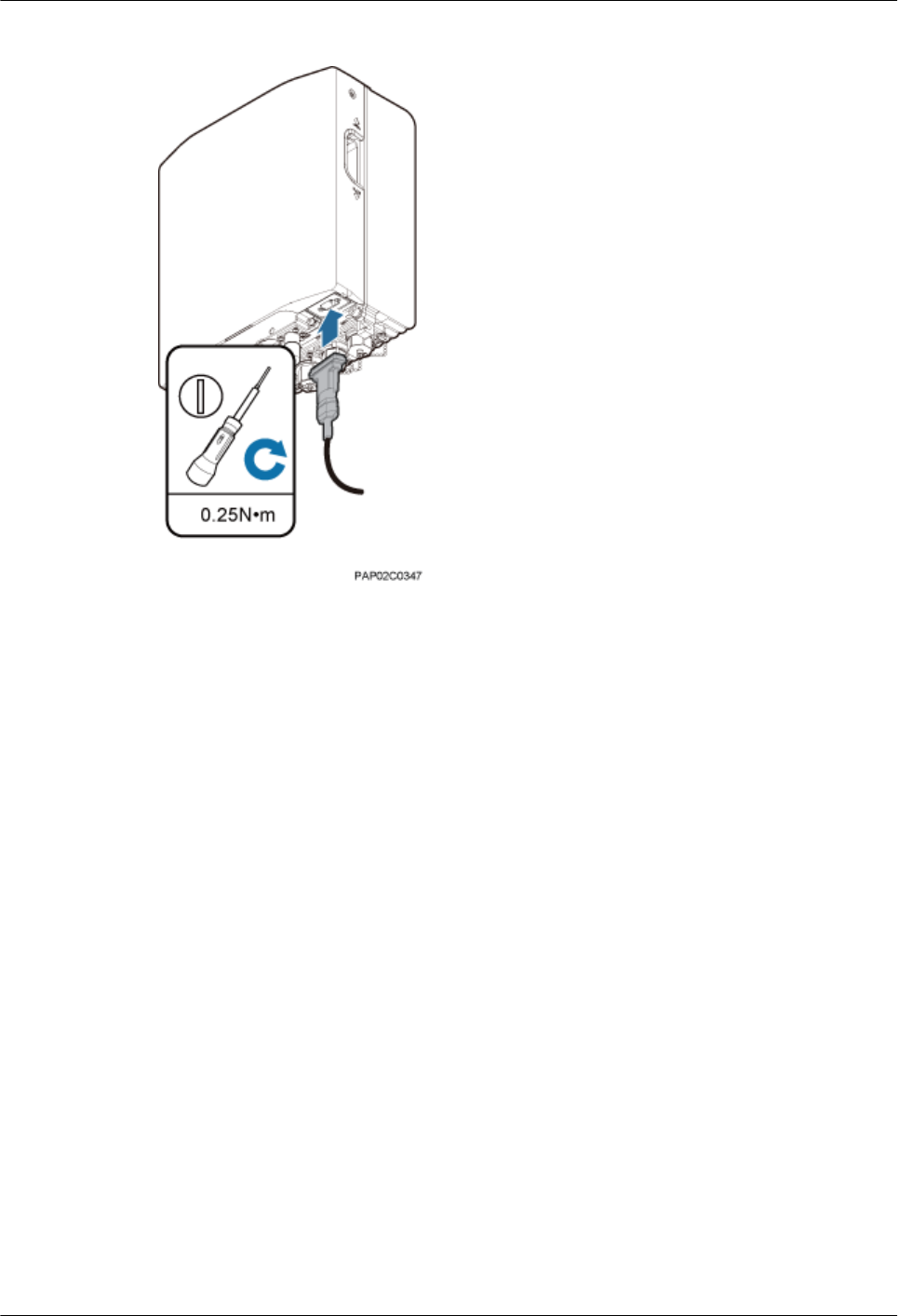
Figure 10-27 Installing the alarm cable
Step 2 Route the cable by referring to 10.1 Cabling Requirements, and then use cable ties to bind the
cable.
Step 3 Label the installed cable by referring to Attaching a Sign Plate Label in Installation Reference.
----End
BTS3902E WCDMA
Installation Guide 10 Installing Cables
Issue 10 (2014-05-16) Huawei Proprietary and Confidential
Copyright © Huawei Technologies Co., Ltd.
158

11 Installing the Housing
About This Chapter
This chapter describes the procedures for installing the upper housing and optional camouflage
shell for a BTS3902E after the BTS3902E and related cables are installed. There are two types
of the BTS3902E. This document uses one type as the example to describe how to install the
housing.
Context
lIf the optional camouflage shell is required, the shell must be installed before the upper
housing is installed, and the upper housing must be removed before the shell is removed.
lThere are two types of the BTS3902E. This document uses one type as the example to
describe.
11.1 (Optional) Installing a Camouflage Shell
This section describes how to install a camouflage shell for a BTS3902E as required.
11.2 Installing the Upper Housing
This section describes how to install the upper housing for a BTS3902E.
BTS3902E WCDMA
Installation Guide 11 Installing the Housing
Issue 10 (2014-05-16) Huawei Proprietary and Confidential
Copyright © Huawei Technologies Co., Ltd.
159
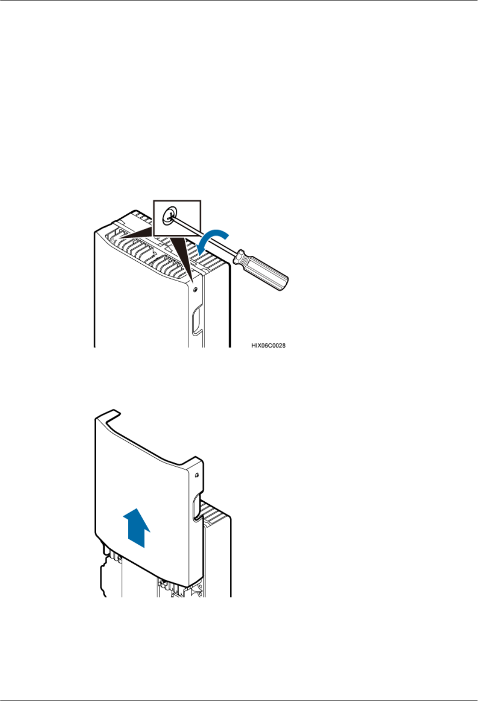
11.1 (Optional) Installing a Camouflage Shell
This section describes how to install a camouflage shell for a BTS3902E as required.
Procedure
Step 1 Use an M4 Phillips screwdriver to loosen the two captive screws from the upper housing, as
shown in Figure 11-1.
Figure 11-1 Loosening the screws from the housing
Step 2 Move the upper housing until it is stopped, as shown in Figure 11-2.
Figure 11-2 Moving the upper housing
Step 3 Install the slots on the camouflage shell to the tabs to secure the shell, as shown in Figure
11-3.
BTS3902E WCDMA
Installation Guide 11 Installing the Housing
Issue 10 (2014-05-16) Huawei Proprietary and Confidential
Copyright © Huawei Technologies Co., Ltd.
160
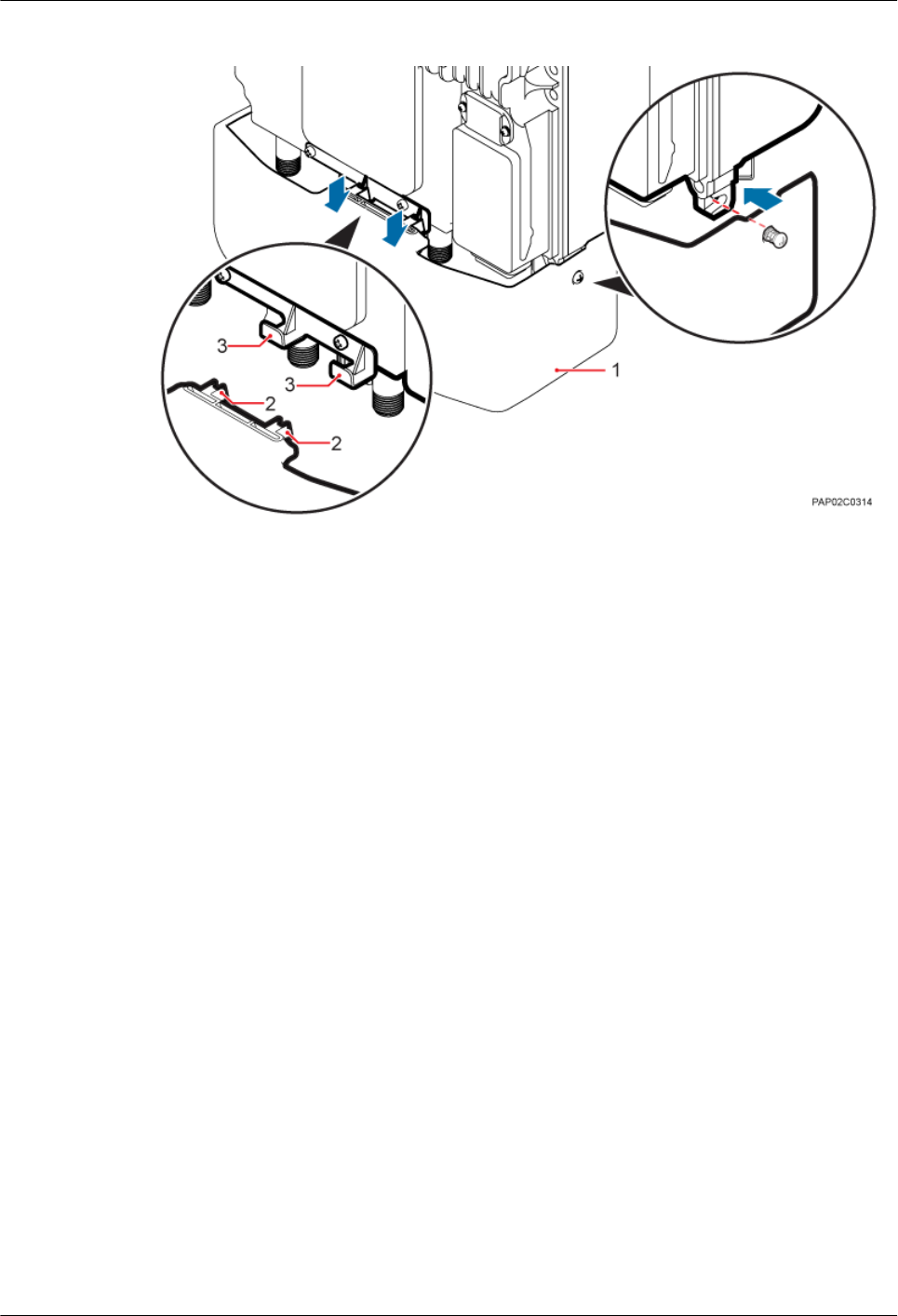
Figure 11-3 Installing the camouflage shell
(1) Camouflage shell (2) Slots (3) Tabs
Step 4 Use an M4 Phillips screwdriver to tighten the two captive screws to 1.2 N·m (10.62 lbf·in.), as
shown in Figure 11-4.
BTS3902E WCDMA
Installation Guide 11 Installing the Housing
Issue 10 (2014-05-16) Huawei Proprietary and Confidential
Copyright © Huawei Technologies Co., Ltd.
161
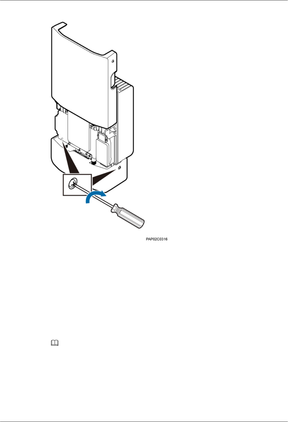
Figure 11-4 Tightening the screws
----End
11.2 Installing the Upper Housing
This section describes how to install the upper housing for a BTS3902E.
Context
NOTE
The camouflage shell is optional. Following uses the BTS3902E equipped with a camouflage shell as an
example.
Procedure
Step 1 Close the housing, and use an M4 Phillips screwdriver to tighten the two captive screws to 1.2
N·m (10.62 lbf·in.), as shown in Figure 11-5.
BTS3902E WCDMA
Installation Guide 11 Installing the Housing
Issue 10 (2014-05-16) Huawei Proprietary and Confidential
Copyright © Huawei Technologies Co., Ltd.
162
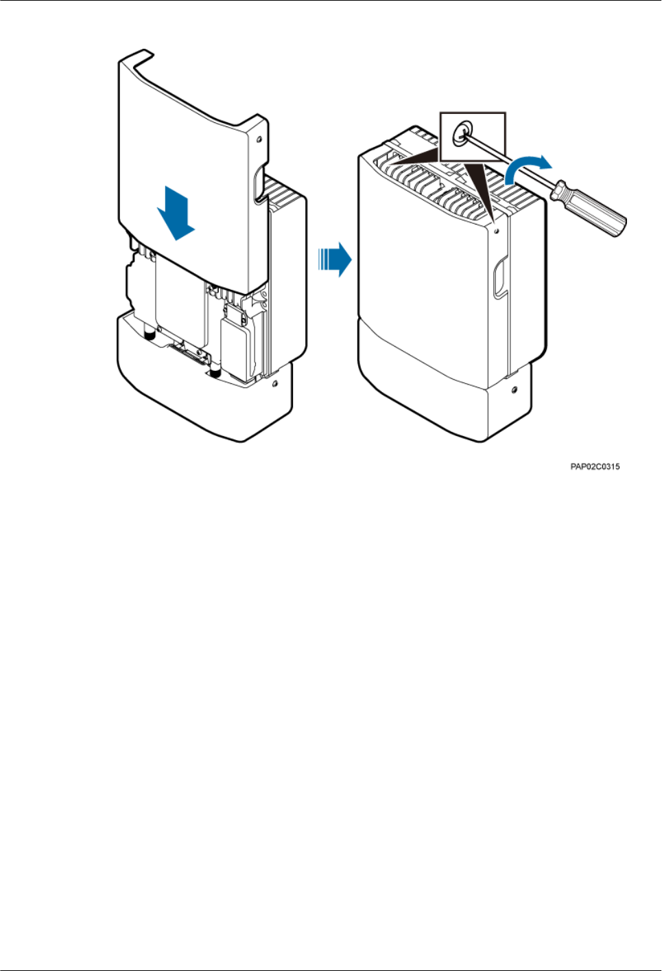
Figure 11-5 Closing the housing and tightening the screws
----End
BTS3902E WCDMA
Installation Guide 11 Installing the Housing
Issue 10 (2014-05-16) Huawei Proprietary and Confidential
Copyright © Huawei Technologies Co., Ltd.
163
12 Checking the BTS3902E Hardware
Installation
This chapter describes how to check the hardware installation after a BTS3902E is installed.
Table 12-1 provides the checklist for the BTS3902E hardware installation.
Table 12-1 Checklist for the BTS3902E Hardware Installation
SN Item
1The position for each device conforms to the engineering drawing and meets the
space requirement. Sufficient space is reserved for equipment maintenance.
2 The BTS3902E is securely installed and the installed BTS3902E has a housing.
3 In the wall-mounted scenario, the holes of the mounting bracket are well aligned
with the holes of the expansion bolt assemblies. In addition, the adapting plates are
secured on the wall evenly and steadily.
4 In the pole-mounted scenario, the supports for the mounting brackets are secured
on the pole.
5 The horizontal error of the BTS3902E is less than 3 mm (0.12 in.), and the vertical
error is not more than 3 mm (0.12 in.).
6 The outdoor cables are properly installed. The vacant ports are covered with
waterproof caps, and the caps are waterproofed.
7 None of power cables and signal cables is short-circuited or reversely connected,
when ground impedance of each PGND cable is ≤ 10 ohms. In addition, all these
cables are not damaged or broken.
8 Power cables and PGND cables are separately bound from other cables.
9 All BTS3902E-related modules are connected to the closest ground bar using
PGND cables.
10 The connectors of each signal cable are intact and securely linked, and these cables
are not damaged or broken.
BTS3902E WCDMA
Installation Guide 12 Checking the BTS3902E Hardware Installation
Issue 10 (2014-05-16) Huawei Proprietary and Confidential
Copyright © Huawei Technologies Co., Ltd.
164
SN Item
11 Labels are correct, legible, and complete at both ends of each cable, feeder, and
jumper.
Table 12-2 provides the checklist for the installation of an AC surge protection box.
Table 12-2 Checklist for the installation of an AC surge protection box
SN Item
1The PG connectors for routing cables on an AC surge protection box are securely
installed.
2 The waterproof fillers on an AC surge protection box are not stripped or broken.
3 OT terminals are securely linked to the cables connecting to an AC surge protection
box. Cable sheaths are not damaged, and the extra length of each cable is cut without
sharp edges.
4 PG connectors are tightened, and waterproof rings are secured.
5 The six screws on the cabling cavity for an AC surge protection box are tightened
properly.
6 The axis between the cover plate for and the case of an AC surge protection box is
not broken, and the surface of the protection box is not scratched.
7 The cable connections for an AC surge protection box meet the requirements in the
operation guide. The cover plate for the cabling cavity is closed after OT terminals
are tightened.
8 An AC surge protection box is powered off before installation and maintenance.
9 The protection grounding of an AC surge protection box and the surge protection
grounding of a building share one group of ground conductors.
10 An AC surge protection box must be installed or maintained in dry conditions.
BTS3902E WCDMA
Installation Guide 12 Checking the BTS3902E Hardware Installation
Issue 10 (2014-05-16) Huawei Proprietary and Confidential
Copyright © Huawei Technologies Co., Ltd.
165
13 Performing a Power-On Check on the
BTS3902E
This chapter describes the procedure for performing a power-on check on the BTS3902E.
NOTICE
After you unpack a BTS3902E, you must power it on within 24 hours. If you power off the
BTS3902E for maintenance, you must restore power to it within 24 hours.
Figure 13-1 shows the BTS3902E power-on check procedure.
BTS3902E WCDMA
Installation Guide 13 Performing a Power-On Check on the BTS3902E
Issue 10 (2014-05-16) Huawei Proprietary and Confidential
Copyright © Huawei Technologies Co., Ltd.
166
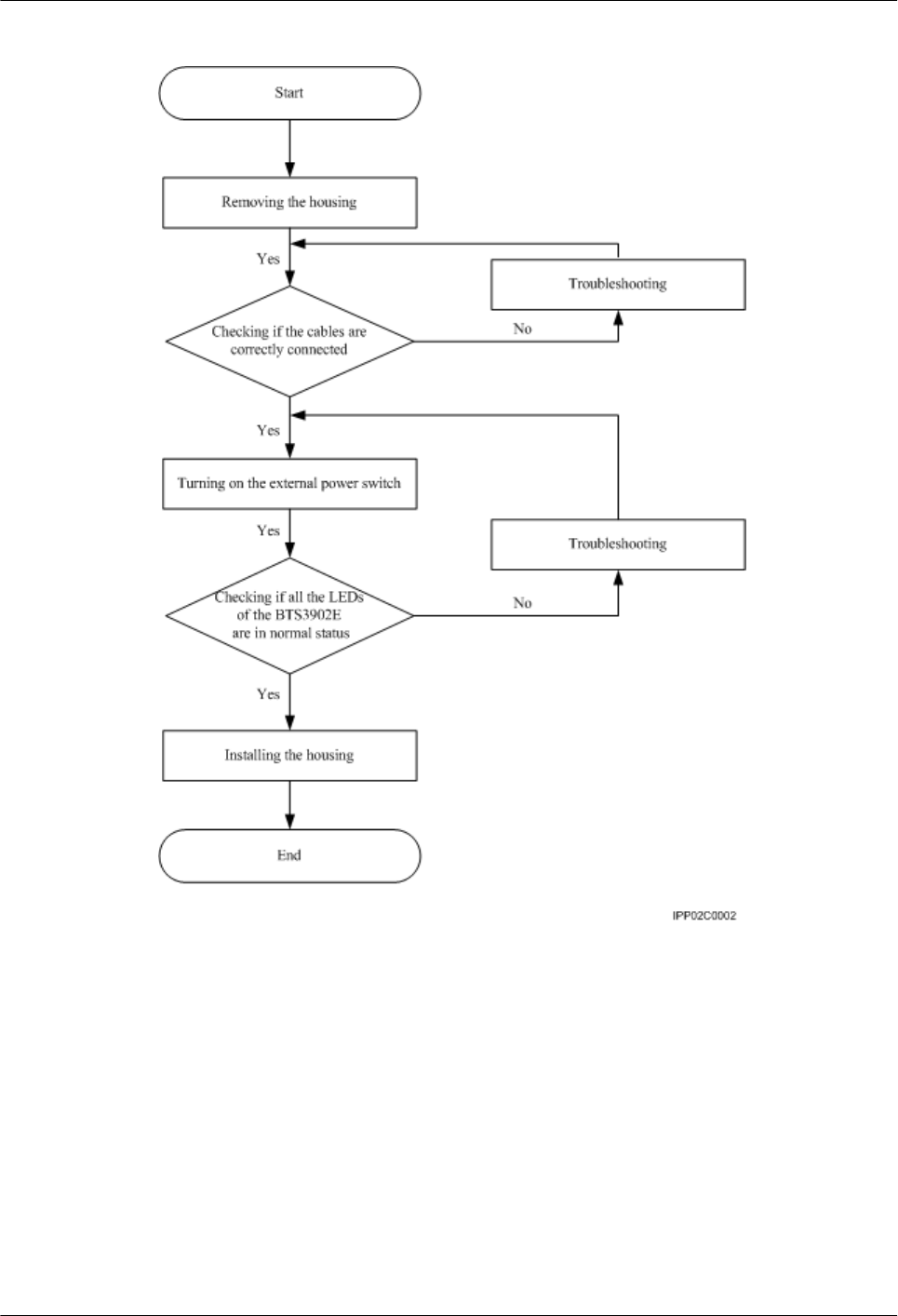
Figure 13-1 BTS3902E power-on check procedure
BTS3902E WCDMA
Installation Guide 13 Performing a Power-On Check on the BTS3902E
Issue 10 (2014-05-16) Huawei Proprietary and Confidential
Copyright © Huawei Technologies Co., Ltd.
167

14 References
About This Chapter
This chapter describes reference information during installation.
14.1 Preparing OT Terminals of the AC Input Power Cable to the AC Surge Protection Box
This section describes for preparing OT terminals for connecting one end of the AC input power
cable to an AC surge protection box.
14.2 Adding a Waterproofed Round DC Connector to the BTS3902E Power Cable on the
BTS3902E Side
This section describes how to add a waterproofed round DC connector to the BTS3902E power
cable on the BTS3902E side.
14.3 Installing a Ground Clip
This section describes how to install a ground clip on a fast Ethernet or gigabit Ethernet (FE/
GE) cable.
BTS3902E WCDMA
Installation Guide 14 References
Issue 10 (2014-05-16) Huawei Proprietary and Confidential
Copyright © Huawei Technologies Co., Ltd.
168
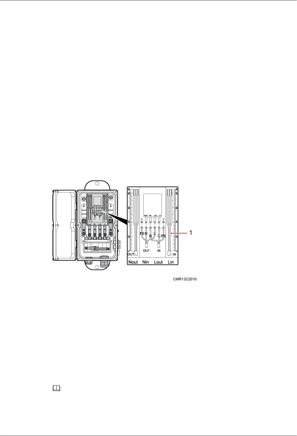
14.1 Preparing OT Terminals of the AC Input Power Cable
to the AC Surge Protection Box
This section describes for preparing OT terminals for connecting one end of the AC input power
cable to an AC surge protection box.
14.1.1 Preparing OT Terminals of the AC Input Power Cable to the
SPD60D
This section describes for preparing OT terminals for connecting one end of the AC input power
cable to an SPD60D.
Context
Figure 14-1 shows the cable diagram on labels.
Figure 14-1 Cable diagram on labels
(1) Cable diagram on labels
Procedure
Step 1 Cut the cable to the required length based on the actual cable route.
Step 2 If the power cable is longer than or equal to 5 m (16.4 ft), cut the corrugated pipe into multiple
5-meter-long pieces; if the cable is shorter than 5 m (16.4 ft), cut the corrugated pipe based on
the actual length of the power cable.
NOTE
Following is based on the power cable longer than or equal to 5 m (16.4 ft).
Step 3 Lead the power cable through corrugated pipes, and add a connector between two corrugated
pipes, as shown in Figure 14-2.
BTS3902E WCDMA
Installation Guide 14 References
Issue 10 (2014-05-16) Huawei Proprietary and Confidential
Copyright © Huawei Technologies Co., Ltd.
169
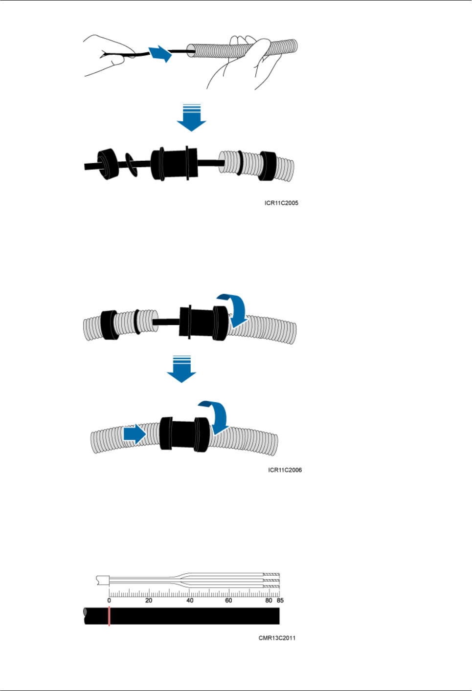
Figure 14-2 Leading the power cable through corrugated pipes
Step 4 Join the corrugated pipes, as shown in Figure 14-3.
Figure 14-3 Joining corrugated pipes
Step 5 Determine the length of the power cable for different operations based on the labels, as shown
in Figure 14-4.
Figure 14-4 Determining the length of the power cable
BTS3902E WCDMA
Installation Guide 14 References
Issue 10 (2014-05-16) Huawei Proprietary and Confidential
Copyright © Huawei Technologies Co., Ltd.
170
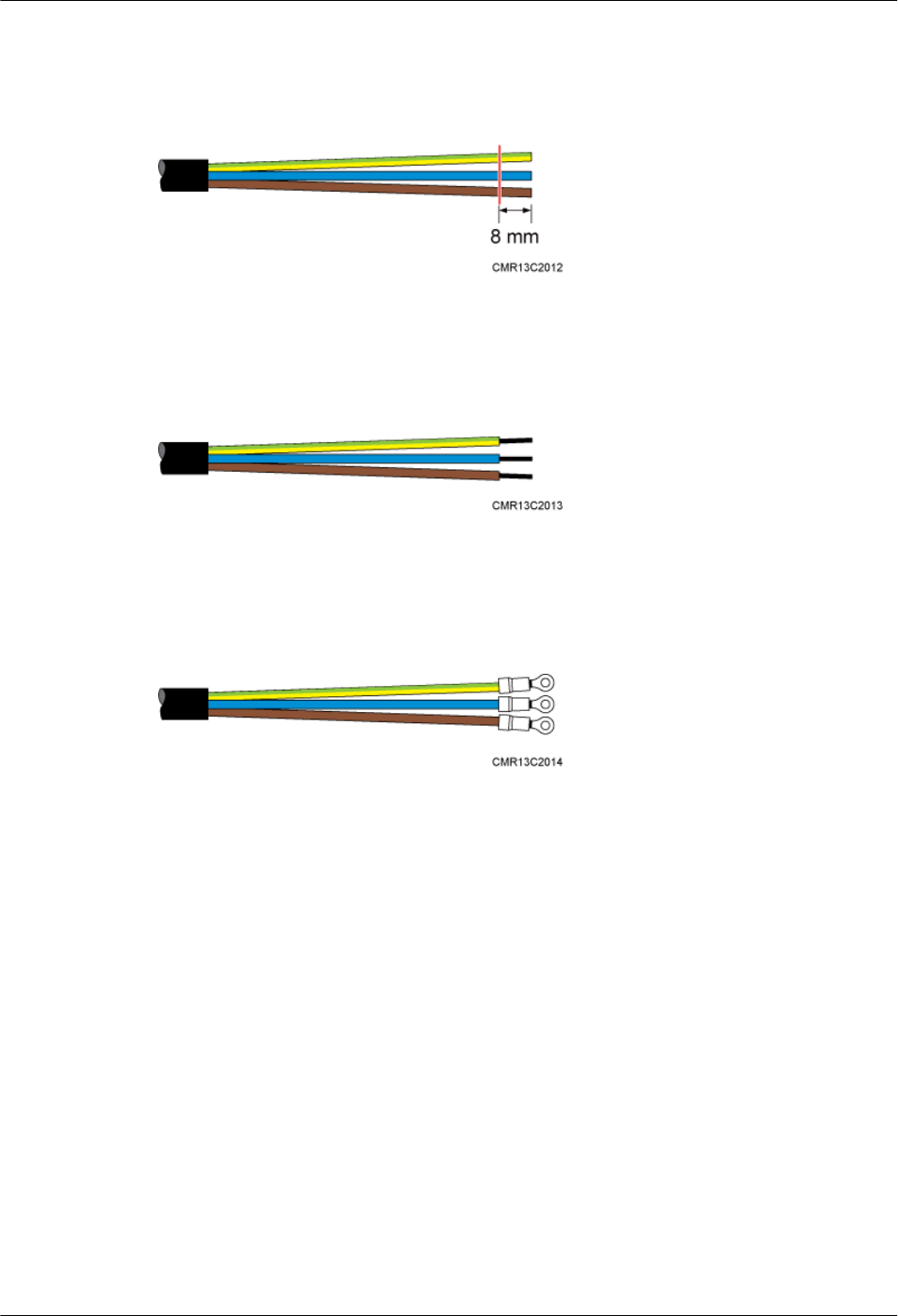
Step 6 Use a utility knife to strip the specified length of the sheath and shield layer off the power cable,
as shown in Figure 14-5.
Figure 14-5 Stripping the specified length of the sheath and shield layer
Step 7 Strip the sheath off each core wire, as shown in Figure 14-6.
Figure 14-6 Stripping the sheath off each core wire
Step 8 Add OT terminals to the three core wires, as shown in Figure 14-7.
Figure 14-7 Adding OT terminals
----End
14.1.2 Preparing OT Terminals to the Power Cable Connected to the
SPM60A
This section describes the procedure for Preparing OT terminals to the power cable connected
to the SPM60A.
Context
Figure 14-8 shows the SPM60A power cable diagram on label.
BTS3902E WCDMA
Installation Guide 14 References
Issue 10 (2014-05-16) Huawei Proprietary and Confidential
Copyright © Huawei Technologies Co., Ltd.
171
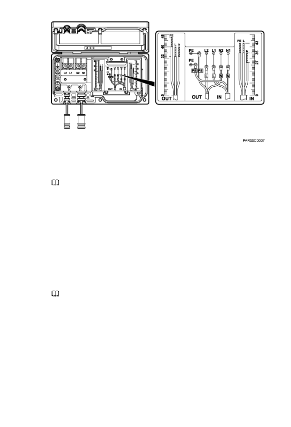
Figure 14-8 SPM60A power cable diagram on label
(1) SPM60A power cable diagram on label
NOTE
lThe OUT cable is a power cable between the SPM60A and the base station. The IN cable is a power
cable between the SPM60A and power equipment.
lThe same method is used for adding OT terminals to the OUT and IN cables, except that different
lengths of jacket need to be stripped off the wires of the OUT and IN cables. This section only uses
adding OT terminals to an IN cable as an example.
Procedure
Step 1 Cut each cable to a length suitable for the actual cable routing.
Step 2 If the power cable is longer than or equal to 5 m (16.4 ft), cut the corrugated pipe into pieces,
each with a length of 5 m (16.4 ft). If the cable is shorter than 5 m, cut the corrugated pipe based
on the actual length of the power cable.
NOTE
The following procedure uses the power cable longer than or equal to 5 m (16.4 ft) as an example.
Step 3 Route the power cable through corrugated pipes, and add a connector between two corrugated
pipes, as shown in Figure 14-9.
BTS3902E WCDMA
Installation Guide 14 References
Issue 10 (2014-05-16) Huawei Proprietary and Confidential
Copyright © Huawei Technologies Co., Ltd.
172
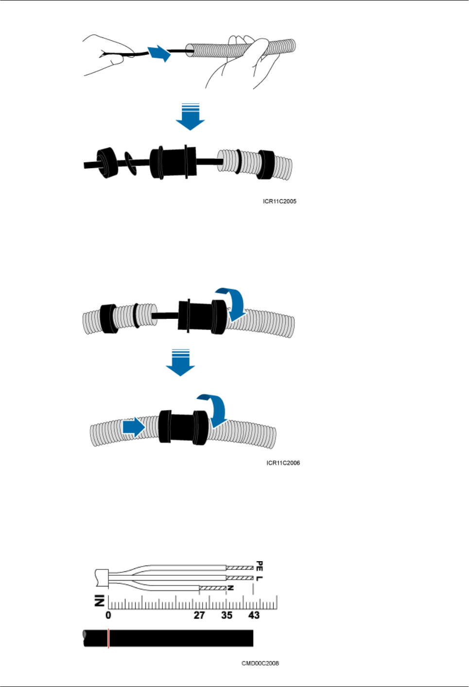
Figure 14-9 Routing the power cable through corrugated pipes
Step 4 Connect the corrugated pipes, as shown in Figure 14-10.
Figure 14-10 Connecting corrugated pipes
Step 5 Determine the length of the cable for different operations based on the power cable diagram on
the SPM60A label, as shown in Figure 14-11.
Figure 14-11 Determining the length of the power cable for the SPM60A
BTS3902E WCDMA
Installation Guide 14 References
Issue 10 (2014-05-16) Huawei Proprietary and Confidential
Copyright © Huawei Technologies Co., Ltd.
173
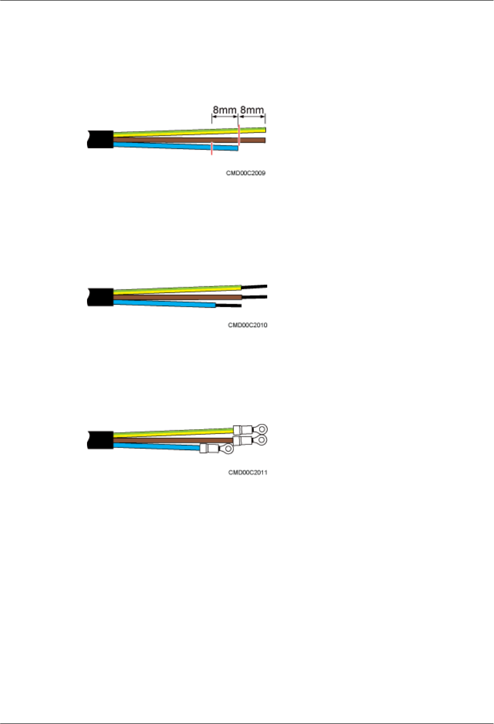
Step 6 Strip a specified length of the jacket and shield layer off the power cable for the SPM60A, as
shown in Figure 14-12.
Figure 14-12 Stripping the jacket and shield layer off the power cable for the SPM60A
Step 7 Strip the jacket off each core wire of the power cable for the SPM60A, as shown in Figure
14-13.
Figure 14-13 Stripping the jacket off the core wires of the power cable for the SPM60A
Step 8 Add OT terminals to core wires for the SPM60A, as shown in Figure 14-14.
Figure 14-14 Adding OT terminals to the core wires of the power cable for the SPM60A
----End
14.2 Adding a Waterproofed Round DC Connector to the
BTS3902E Power Cable on the BTS3902E Side
This section describes how to add a waterproofed round DC connector to the BTS3902E power
cable on the BTS3902E side.
Context
Table 14-1 lists and Figure 14-15 illustrates the pin assignment for the wires of the
BTS3902E power cable.
BTS3902E WCDMA
Installation Guide 14 References
Issue 10 (2014-05-16) Huawei Proprietary and Confidential
Copyright © Huawei Technologies Co., Ltd.
174
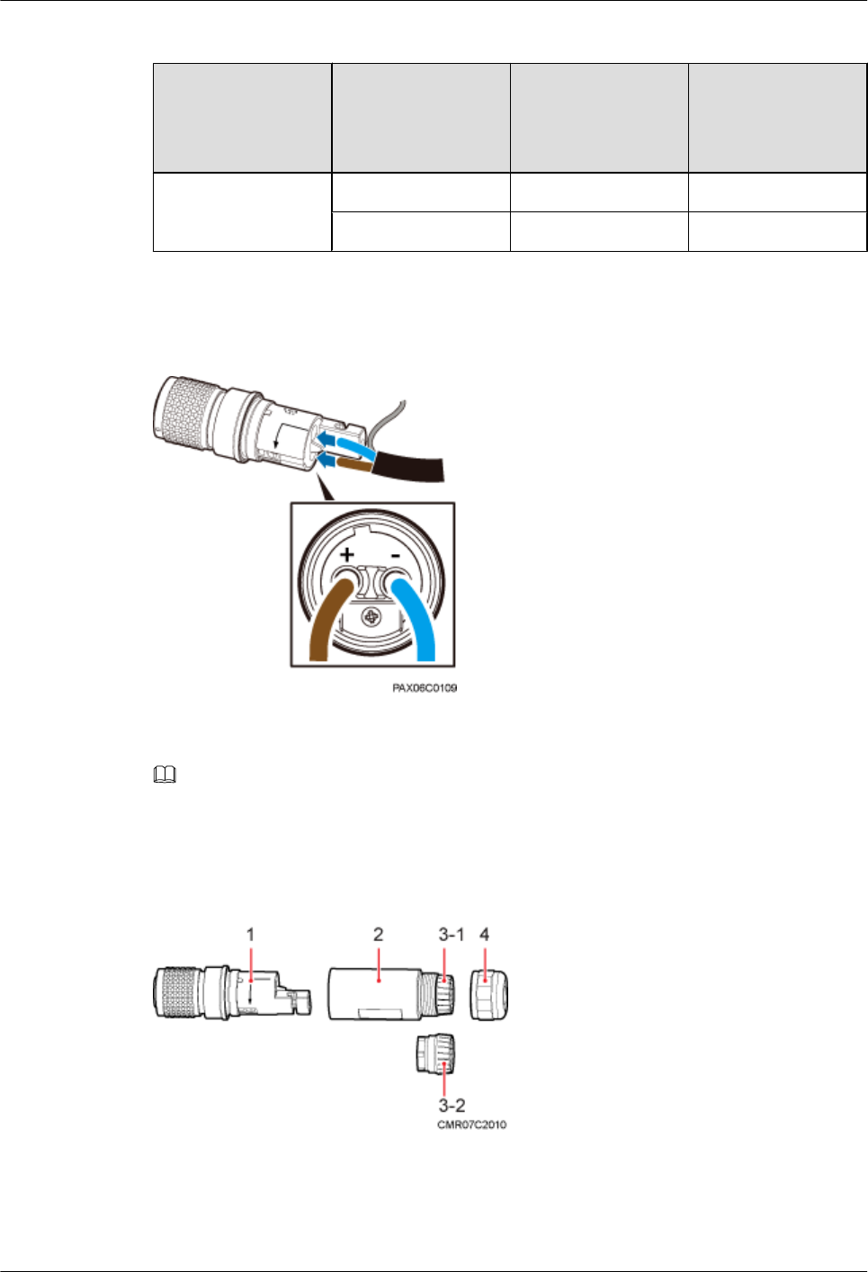
Table 14-1 Cable description
BTS3902E Side Cable
Color of the Core
Wire (North
American
Standard)
Color of the Core
Wire (European
Standard)
Waterproofed round
DC connector
NEG(-) wire Blue Blue
RTN(+) wire Black Brown
Figure 14-15 Connections of the BTS3902E power cable (using the European standard as an
example)
NOTE
The colors and structures of cables vary depending on the region.
Figure 14-16 shows the components of a waterproofed round DC connector.
Figure 14-16 Material list
(1) Protective cover (2) Socket (3) Clamping jaw 1 (4) Nut
BTS3902E WCDMA
Installation Guide 14 References
Issue 10 (2014-05-16) Huawei Proprietary and Confidential
Copyright © Huawei Technologies Co., Ltd.
175
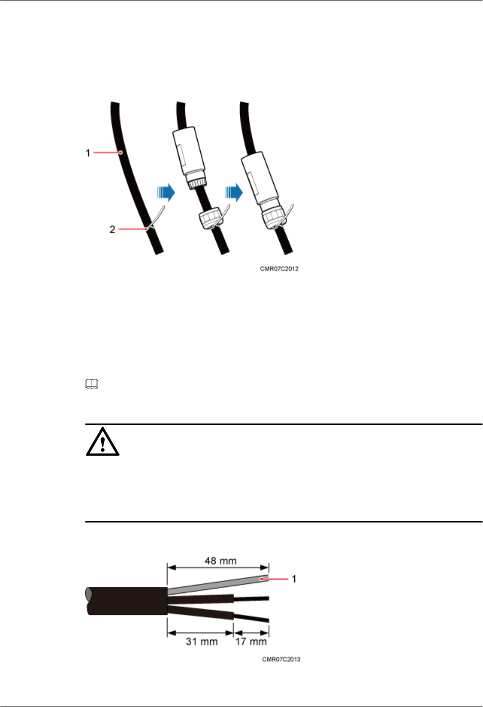
Procedure
Step 1 Leave a specified length of the cable, lead the nut, clamping jaw (including the waterproof
gasket), and socket through the cable, and partially tighten the nut, as shown in Figure 14-17.
Figure 14-17 Leading the nut, clamping jaw, waterproof gasket, and socket through the cable
(1) Power Cable (2) Plastic cable tie
Step 2 Use the stripping ruler card to measure correct lengths. Strip about 48 mm (1.89 in.) of the sheath
off the cable and 17 mm (0.67 in.) off the sheath of each wire, and assemble the shield layer, as
shown in Figure 14-18.
NOTE
The stripping ruler card is delivered with the components of the connector.
NOTICE
lUse a pair of diagonal pliers to cut the padding.
lGently strip the insulation sheath to avoid damage to the conductor metal.
lEnsure that the wires do not split during cable stripping.
Figure 14-18 Cable stripping
(1) Shield layer
BTS3902E WCDMA
Installation Guide 14 References
Issue 10 (2014-05-16) Huawei Proprietary and Confidential
Copyright © Huawei Technologies Co., Ltd.
176
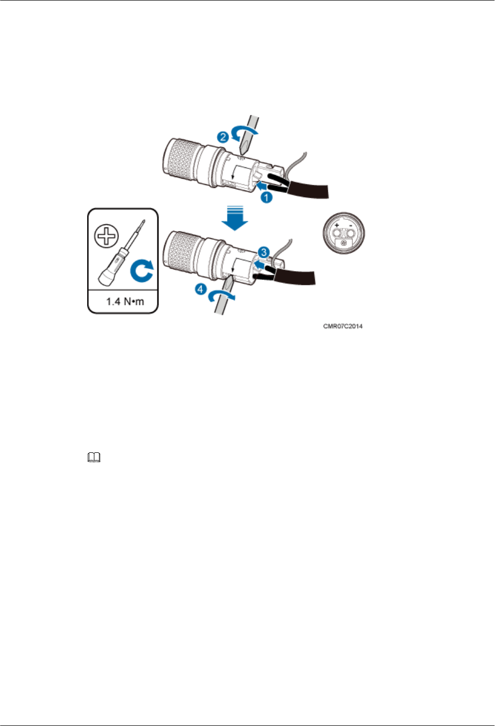
Step 3 Connect the black or brown core wire labeled RTN(+) to the + port on the connector and the
blue core wire labeled NEG(-) to the - port. Then use a Phillips screwdriver to tighten the two
screws on both sides to 1.4 N·m (12.39 lbf·in.), as shown in Figure 14-19.
Figure 14-19 Connecting the core wires to the connector and tightening the core wires
Step 4 Pull each wire slightly to check whether the connections are secure. If the cable slides outward
or the wire of the cable is exposed outside the hole for the cable, remove the cable, cut the split
wires, and then strip the jacket and install the cable again.
Step 5 Insert the assembled shield layer into the shield slot, and tighten the screw at the bottom to 1.4
N·m (12.39 lbf·in.) to secure the shield layer, as shown in Figure 14-20.
NOTE
Cut the extra shield layer using the diagonal pliers.
BTS3902E WCDMA
Installation Guide 14 References
Issue 10 (2014-05-16) Huawei Proprietary and Confidential
Copyright © Huawei Technologies Co., Ltd.
177
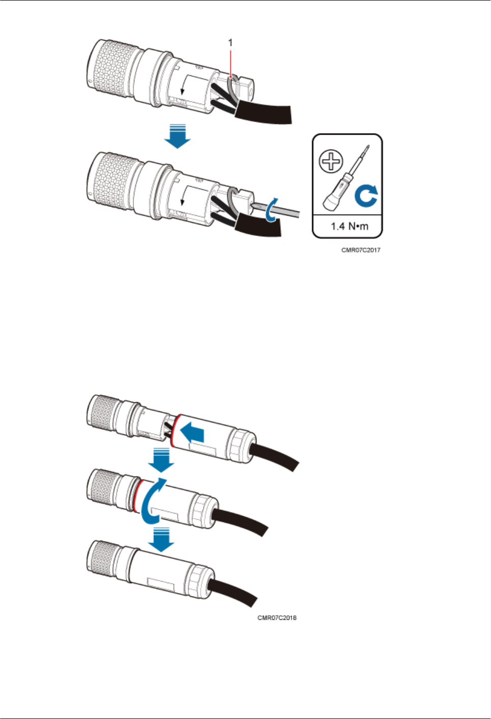
Figure 14-20 Installing and securing the shield layer
(1) Shield layer
Step 6 Use your hand to screw the gasket and the protective cover until the red line on the gasket cannot
be seen, as shown in Figure 14-21.
Figure 14-21 Tightening the gasket and the protective cover
Step 7 Partially tighten the nuts and socket, and then use a combination wrench (capacity: 28 mm [1.1
in.]) to secure the nuts, as shown in Figure 14-22.
BTS3902E WCDMA
Installation Guide 14 References
Issue 10 (2014-05-16) Huawei Proprietary and Confidential
Copyright © Huawei Technologies Co., Ltd.
178

Figure 14-22 Tightening the nuts and socket
Step 8 Use a multimeter to check the connection reliability, as shown in Figure 14-23.
Figure 14-23 Using a multimeter to check the connection reliability
NOTICE
lThe ports of the connector cannot be short-circuited.
lMetal jackets and ports of the connector cannot be short-circuited.
Step 9 If the device is installed outdoors, the connector must be wrapped with three layers of PVC
insulation tape, as shown in Figure 14-24.
NOTICE
Do not wrap the connector with more than three layers of PVC insulation tape.
BTS3902E WCDMA
Installation Guide 14 References
Issue 10 (2014-05-16) Huawei Proprietary and Confidential
Copyright © Huawei Technologies Co., Ltd.
179
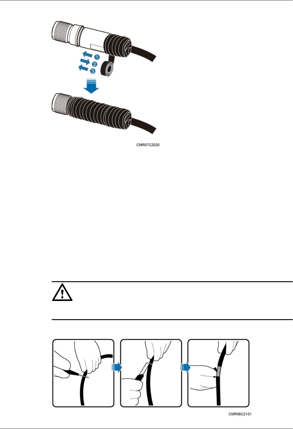
Figure 14-24 Wrap three layers of PVC insulation tape
----End
14.3 Installing a Ground Clip
This section describes how to install a ground clip on a fast Ethernet or gigabit Ethernet (FE/
GE) cable.
Procedure
Step 1 Determine the position for installing the ground clip on the cable based on the actual cable route.
Step 2 Use a utility knife to strip the sheath off the FE/GE cable for about 32 mm (1.26in.) to expose
the shield layer, as shown in Figure 14-25.
NOTICE
Do not damage the shield layer when stripping the sheath off the cable.
Figure 14-25 Stripping the sheath off the FE/GE cable
BTS3902E WCDMA
Installation Guide 14 References
Issue 10 (2014-05-16) Huawei Proprietary and Confidential
Copyright © Huawei Technologies Co., Ltd.
180
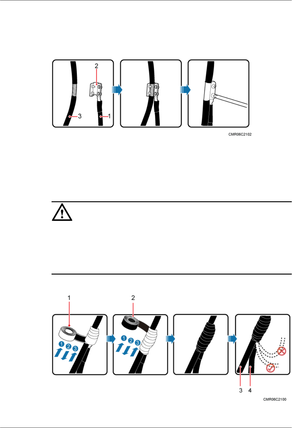
Step 3 Install the ground clip on the shield layer of the cable, and then use a screwdriver to tighten the
screws on the ground clip, as shown in Figure 14-26.
Figure 14-26 Tightening the screws on a ground clip
(1) Ground cable (2) Ground clip (3) FE/GE cable
Step 4 Wrap three layers of waterproof tape and three layers of polyvinyl chloride (PVC) insulation
tape at the ground clip.
NOTICE
lWrap the tape around the clip from bottom up, then from top down, and finally from bottom
up. Do not cut the tape until all the three layers of the tape are already wrapped. When
wrapping tape, be sure that each layer of tape overlaps more than 50% of the preceding layer.
lThe degree between the ground cable and the FE/GE cable is not greater than 15°. When the
FE/GE cable is routed vertically, the ground cable must be routed downwards.
Figure 14-27 Wrapping waterproof tape and PVC insulation tape
(1) Waterproof tape (2) PVC insulation tape (3) FE/GE cable (4) Ground cable
BTS3902E WCDMA
Installation Guide 14 References
Issue 10 (2014-05-16) Huawei Proprietary and Confidential
Copyright © Huawei Technologies Co., Ltd.
181

Step 5 Connect the ground cable to an external ground bar.
----End
BTS3902E WCDMA
Installation Guide 14 References
Issue 10 (2014-05-16) Huawei Proprietary and Confidential
Copyright © Huawei Technologies Co., Ltd.
182