Huawei Technologies BTS3911E Micro BTS User Manual UserManual
Huawei Technologies Co.,Ltd Micro BTS UserManual
UserManual.wiki
>
Huawei Technologies
>
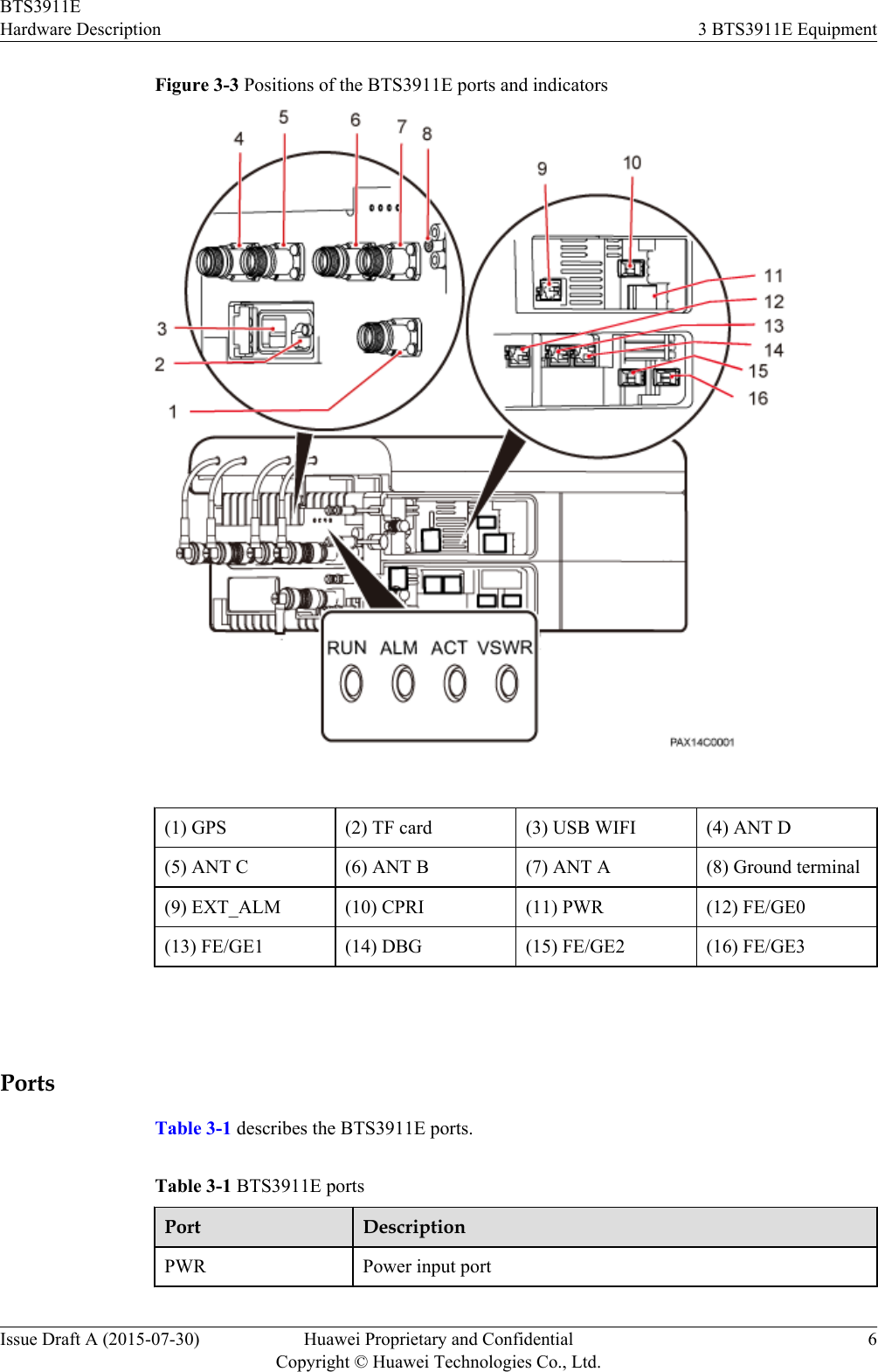
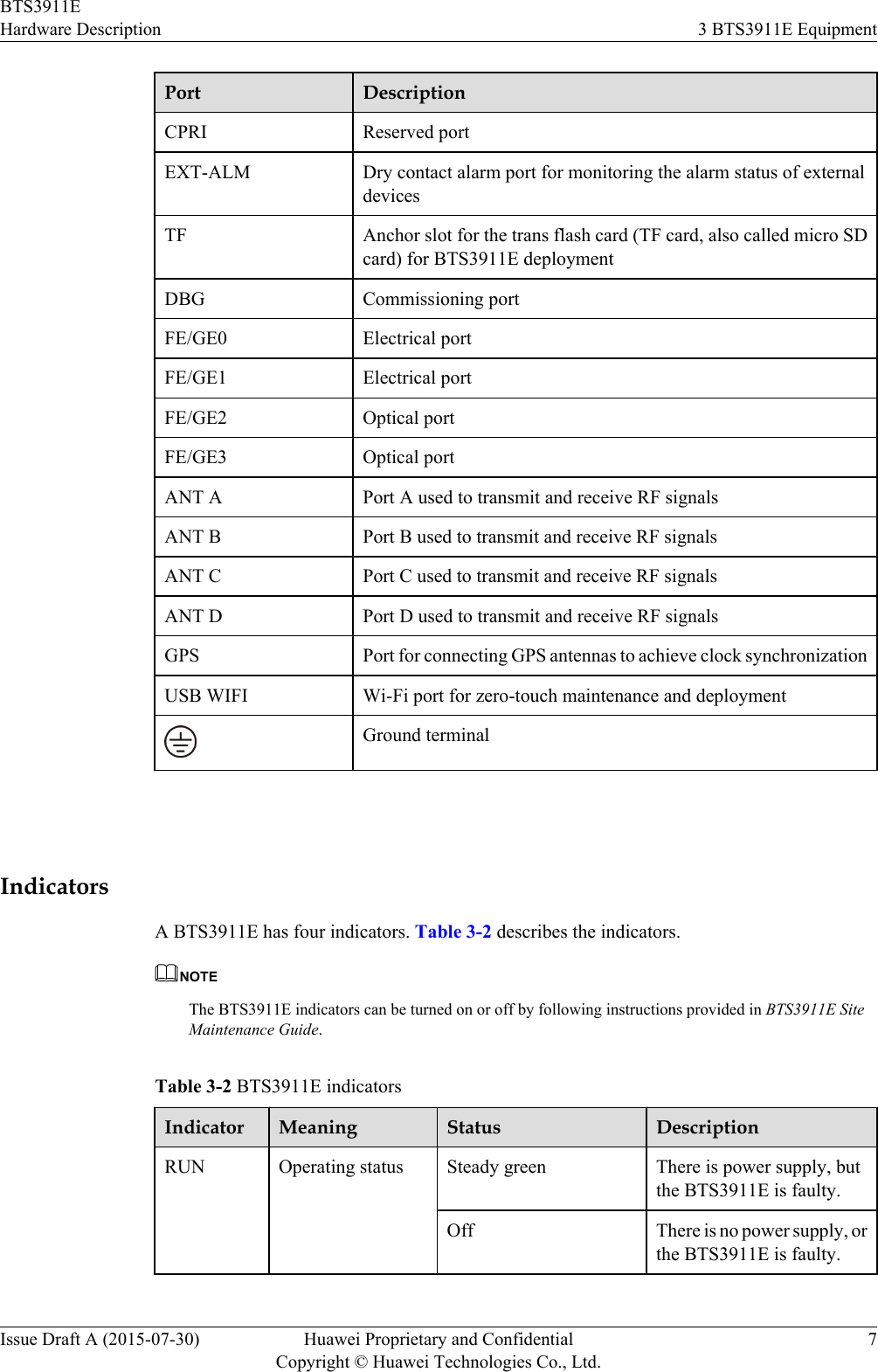
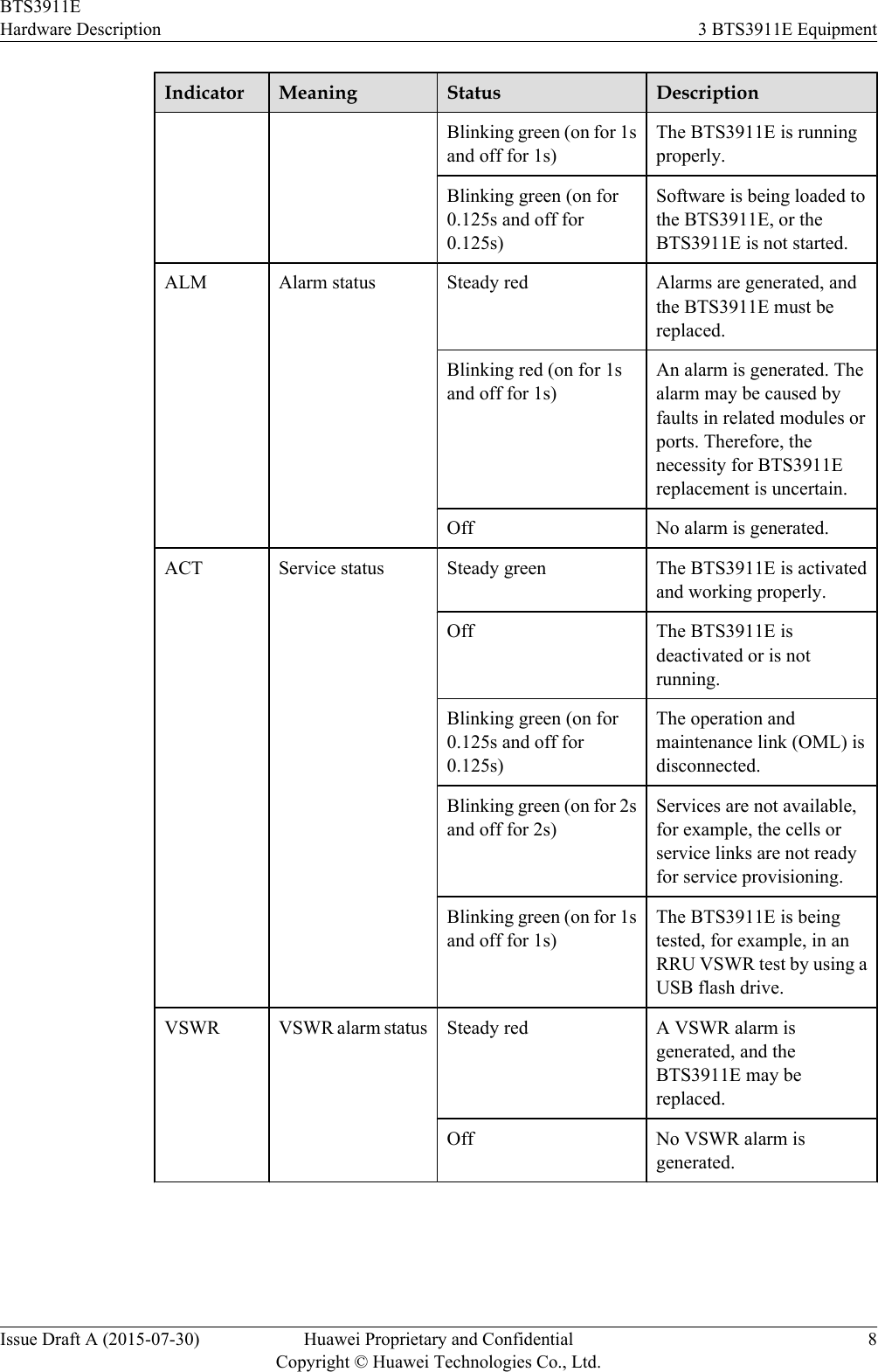
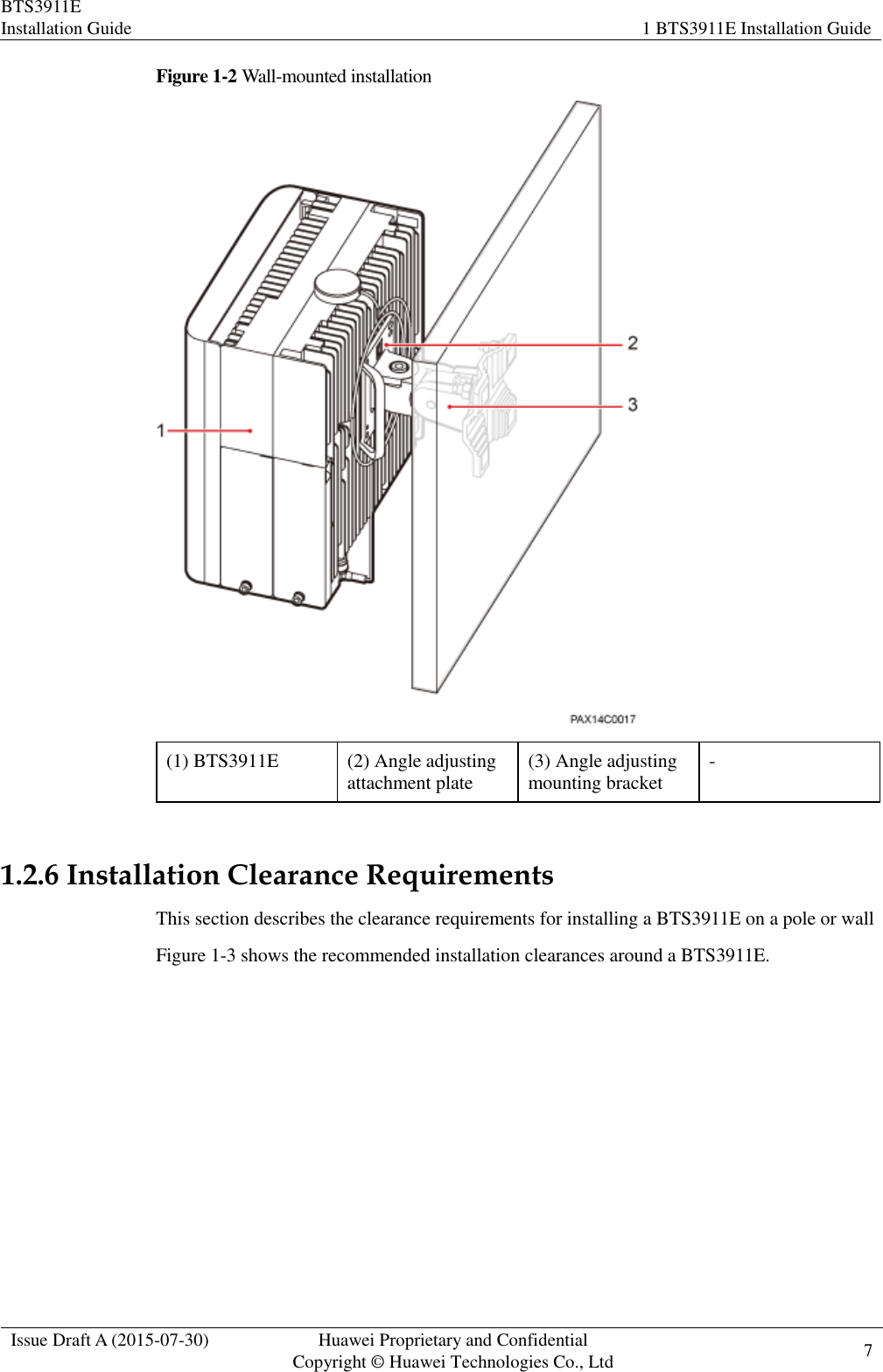
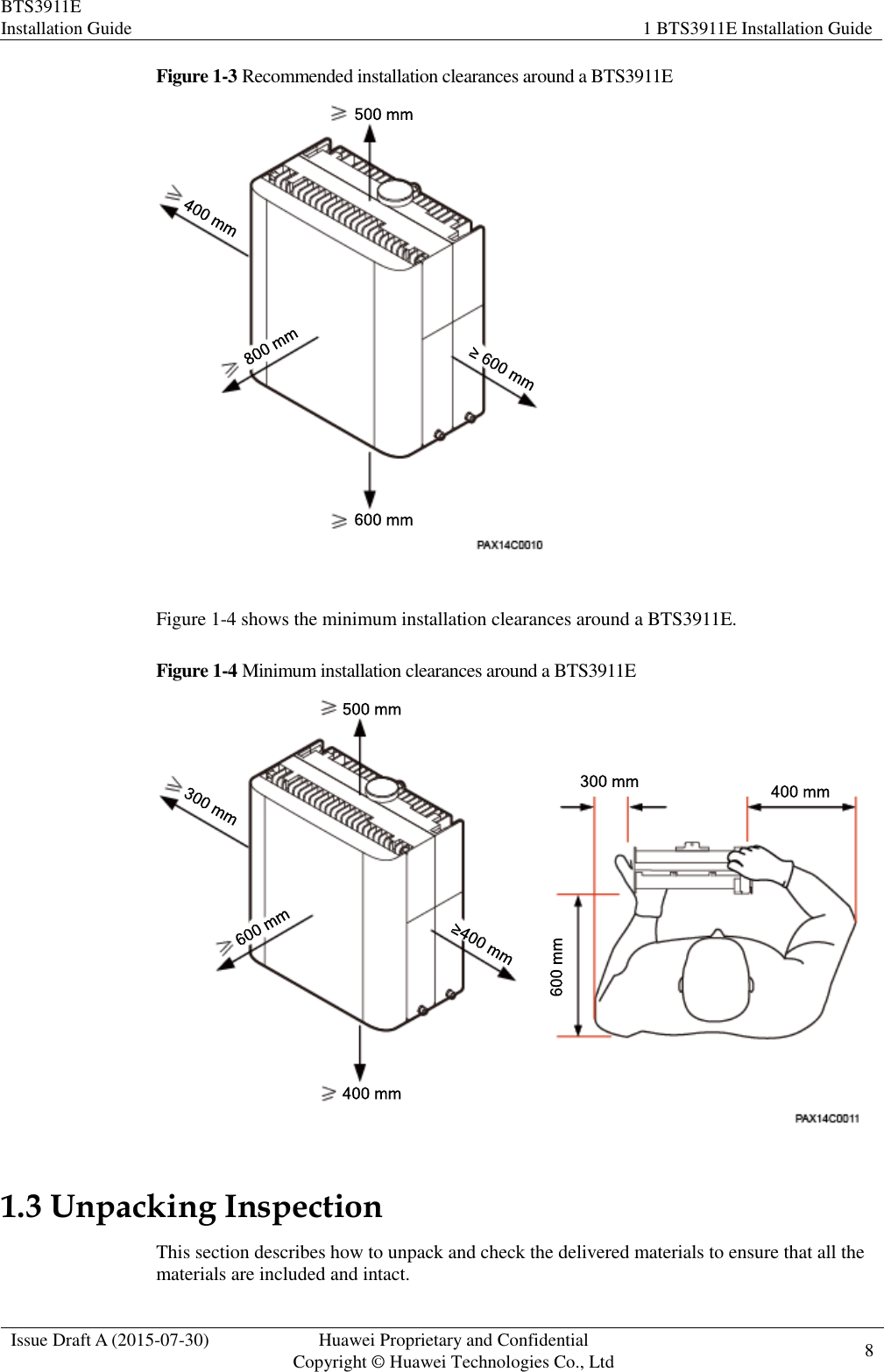
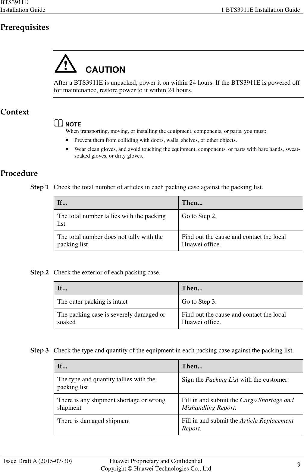
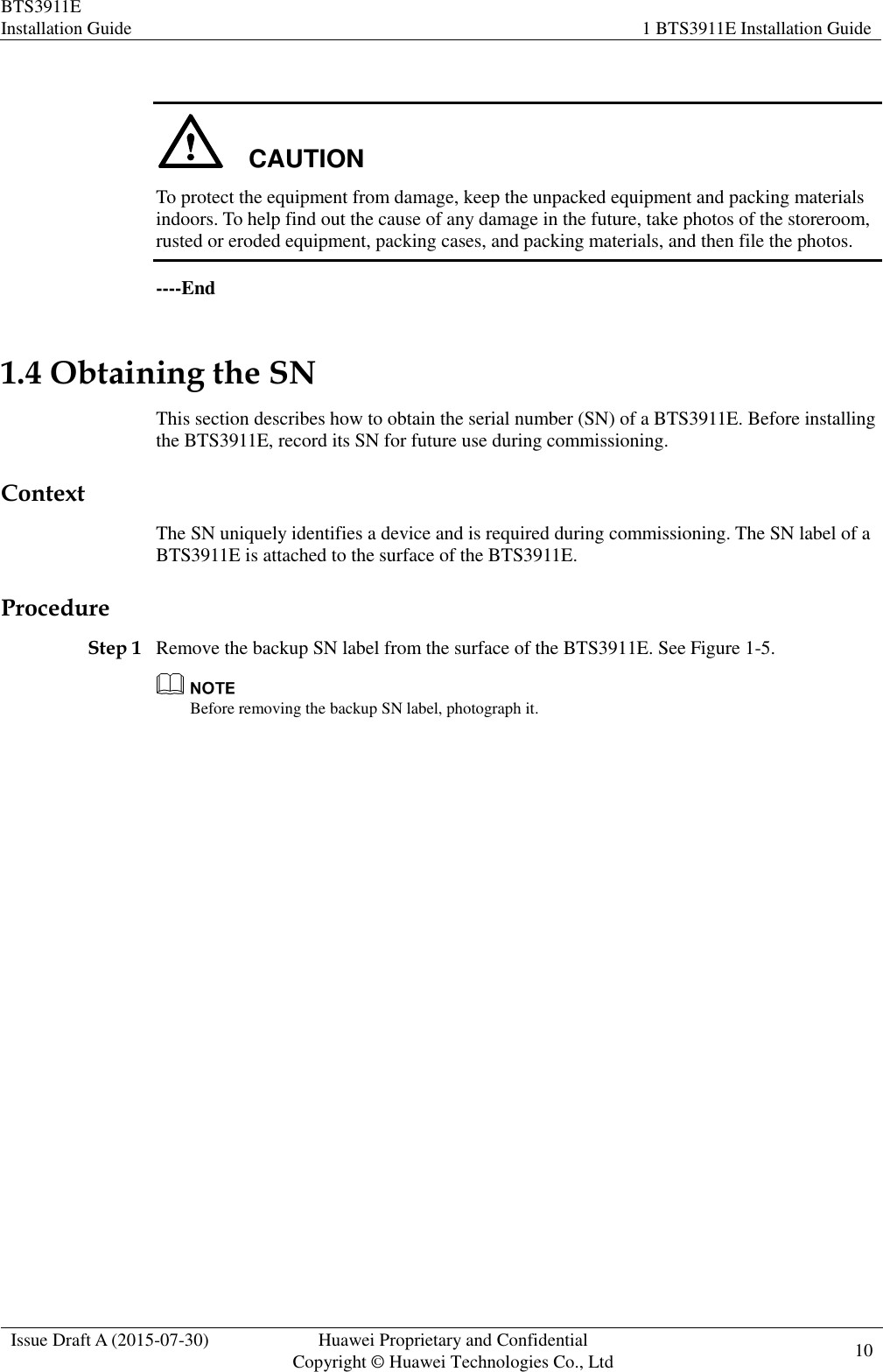
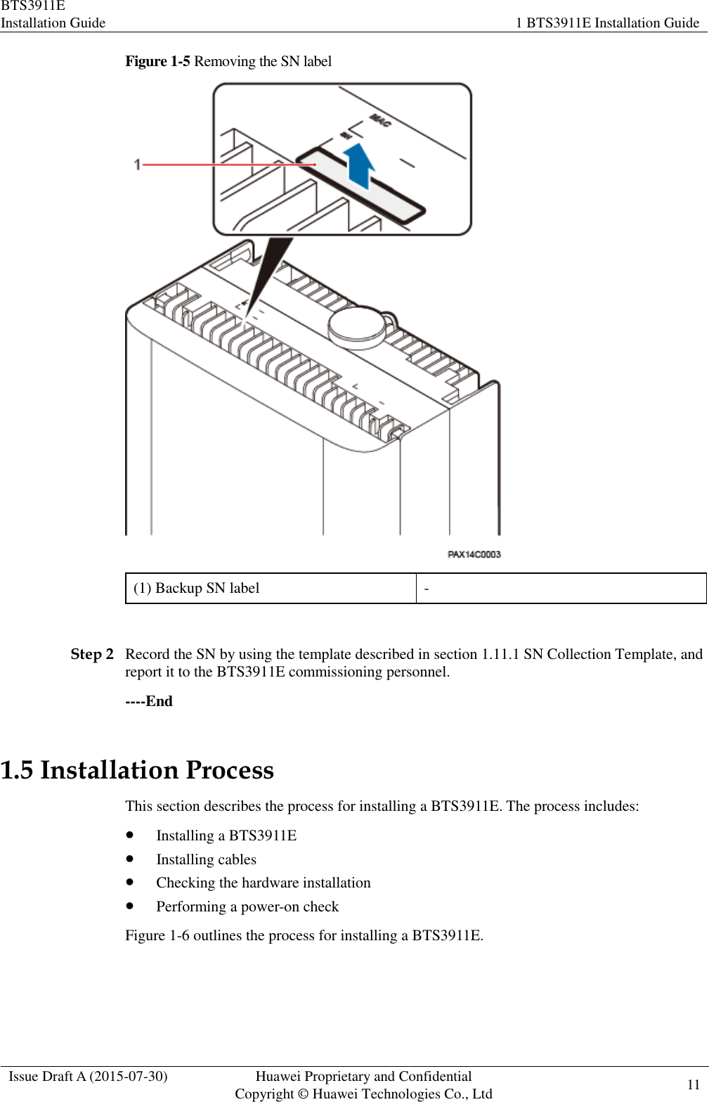
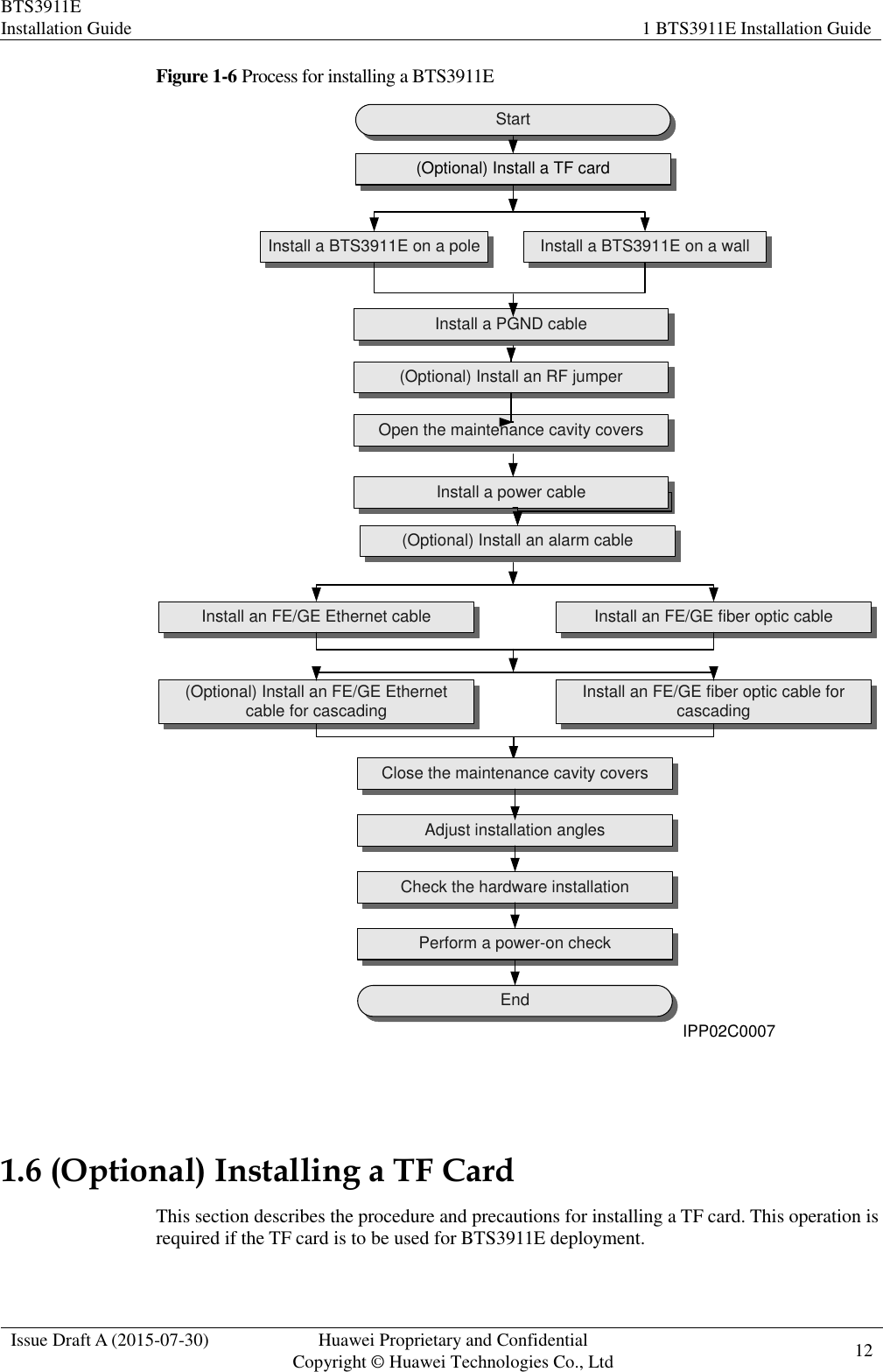
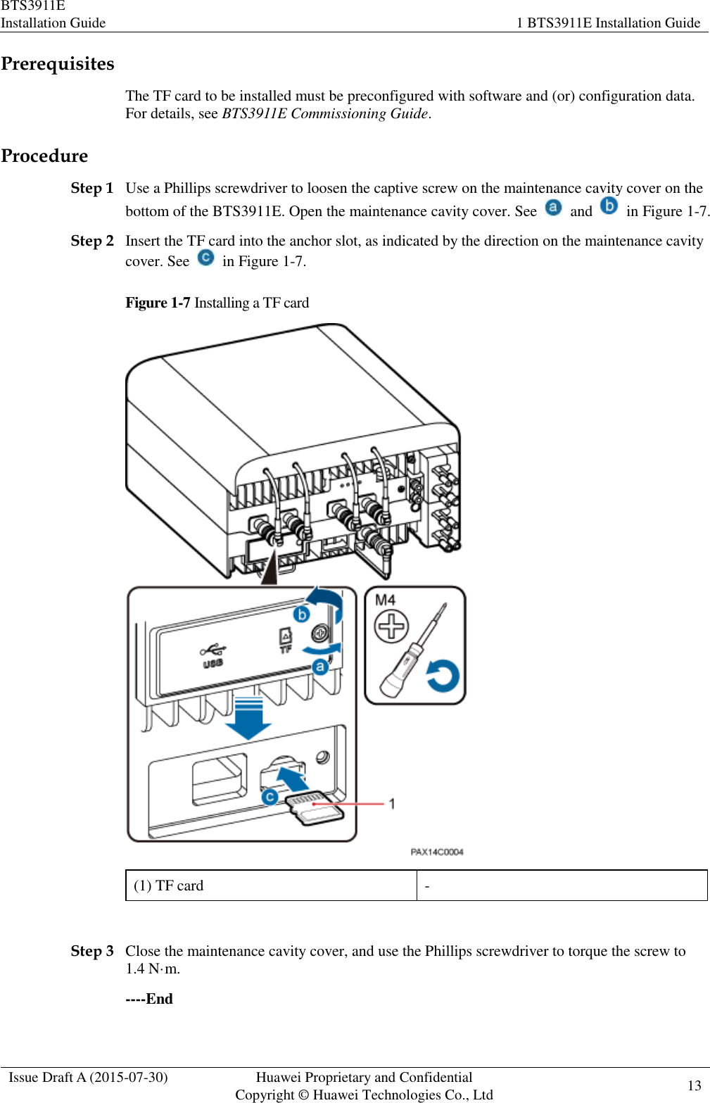
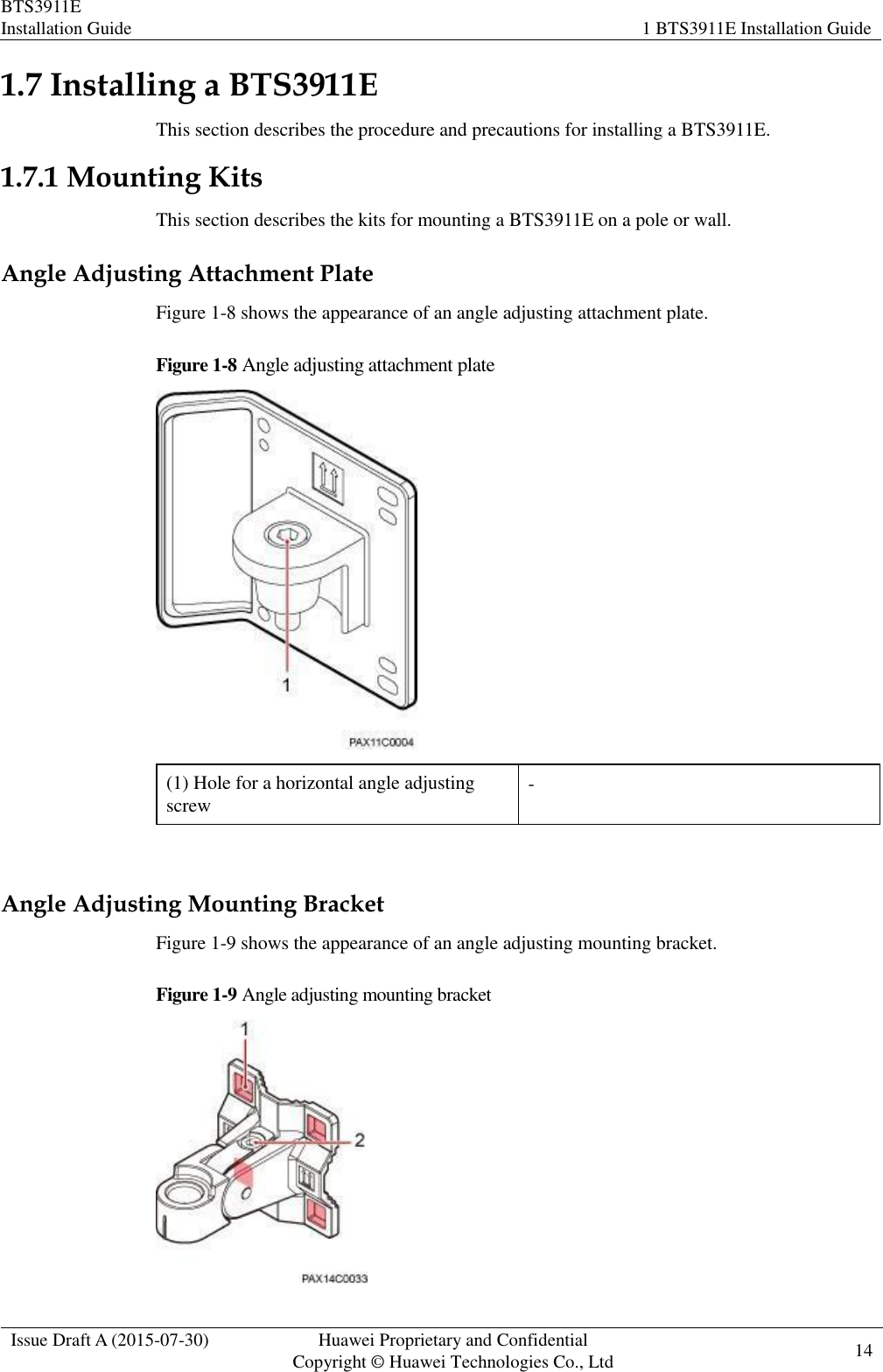
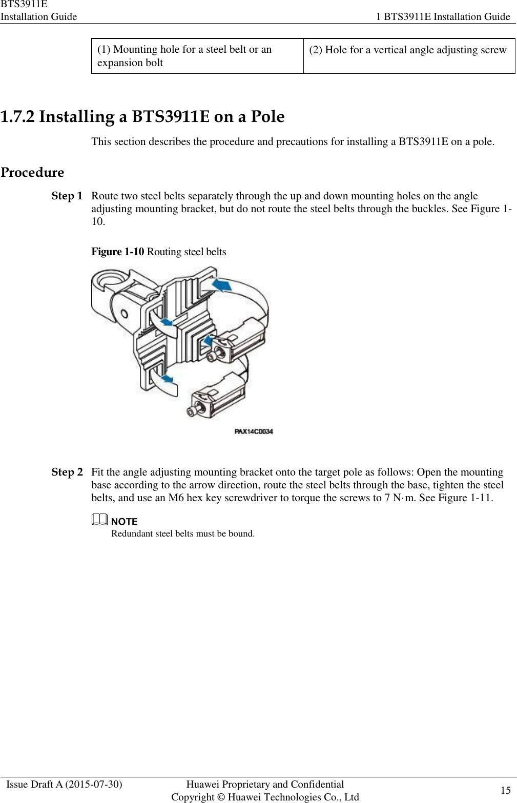
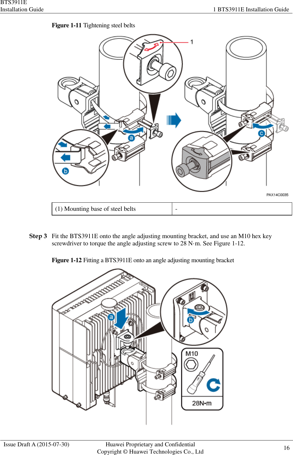
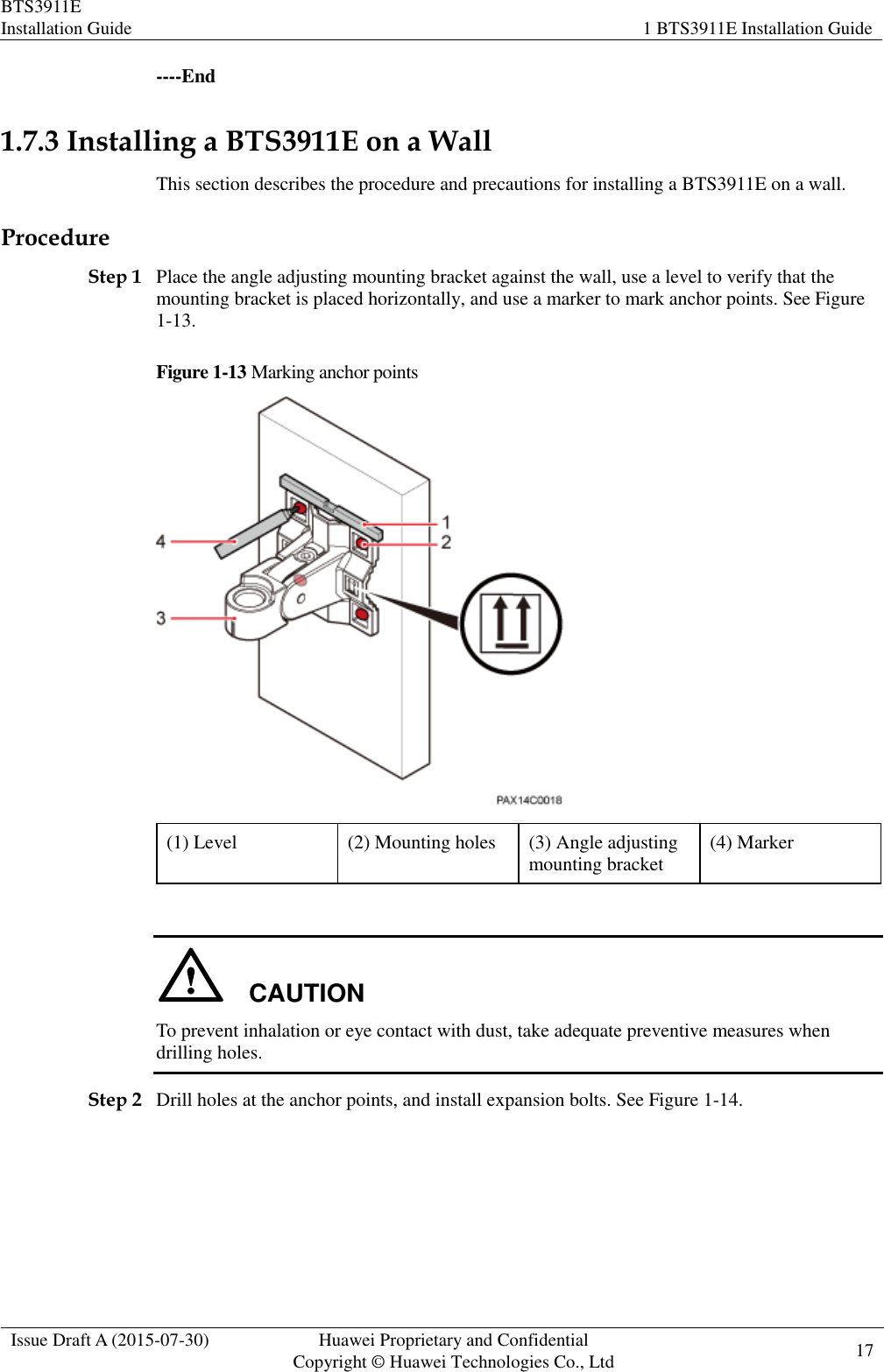
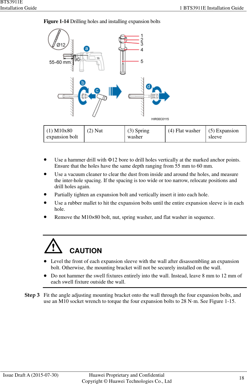
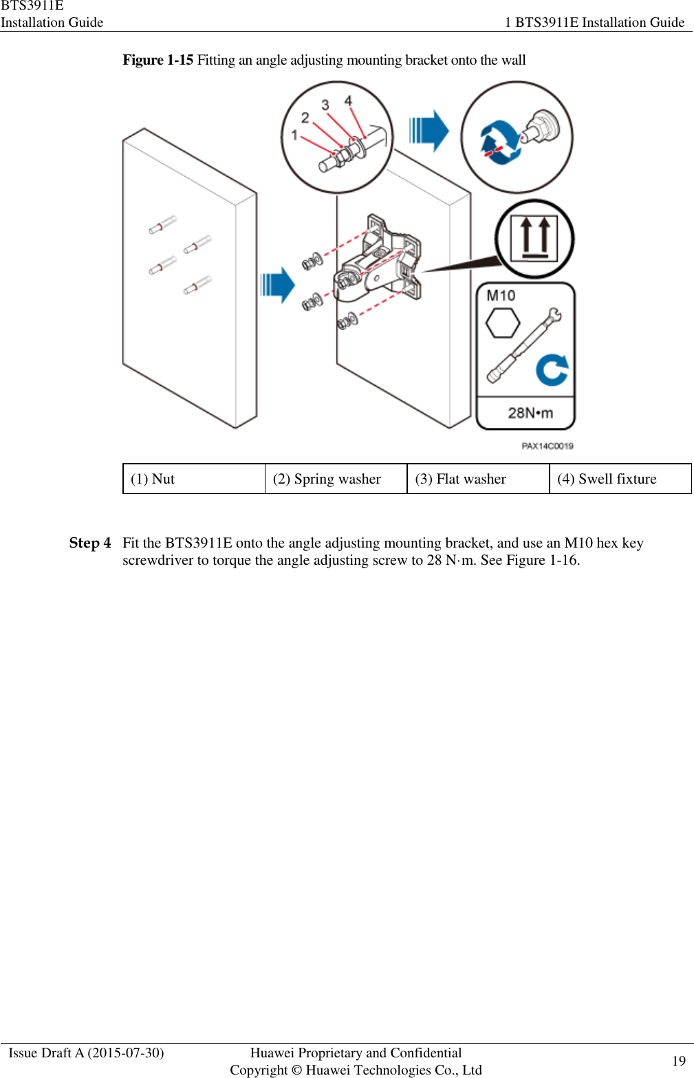
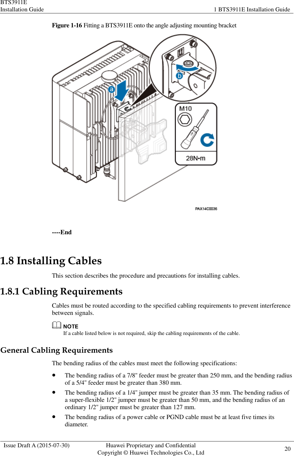
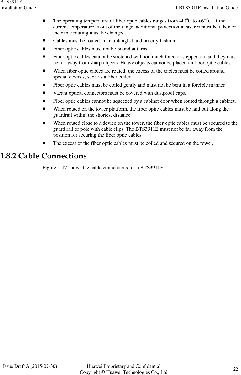
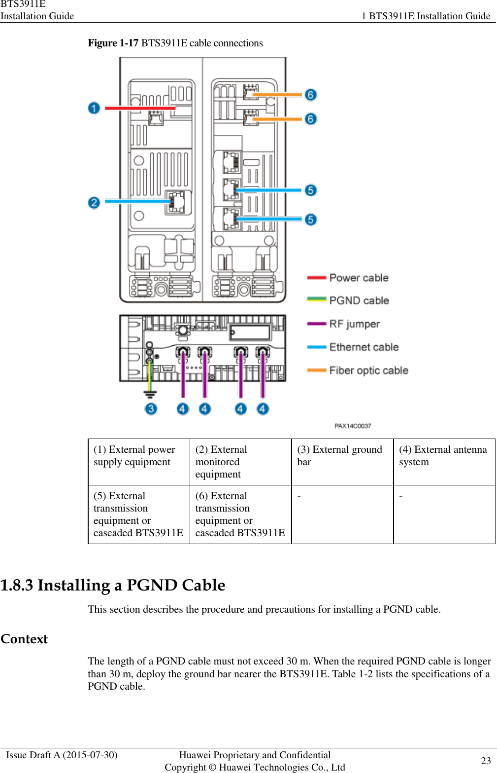
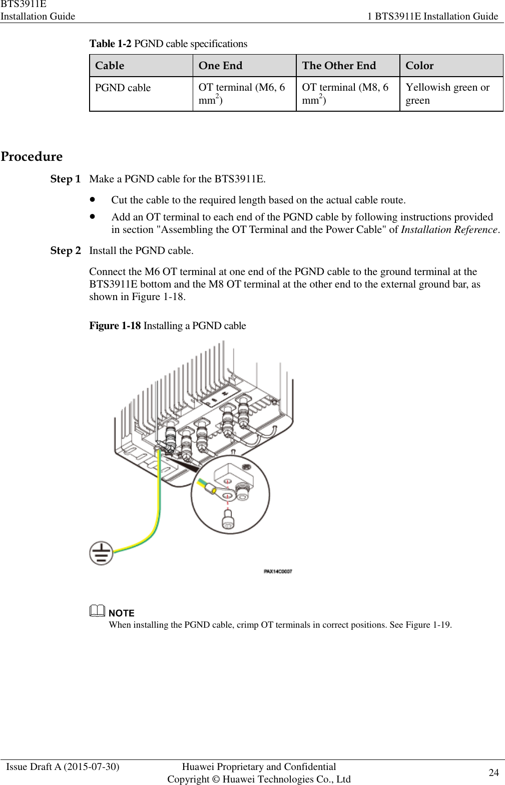
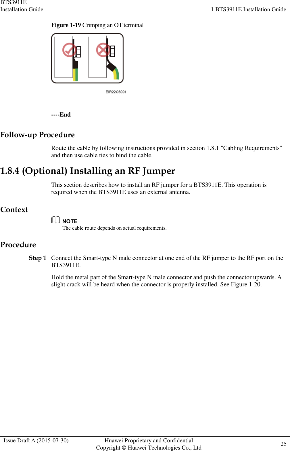
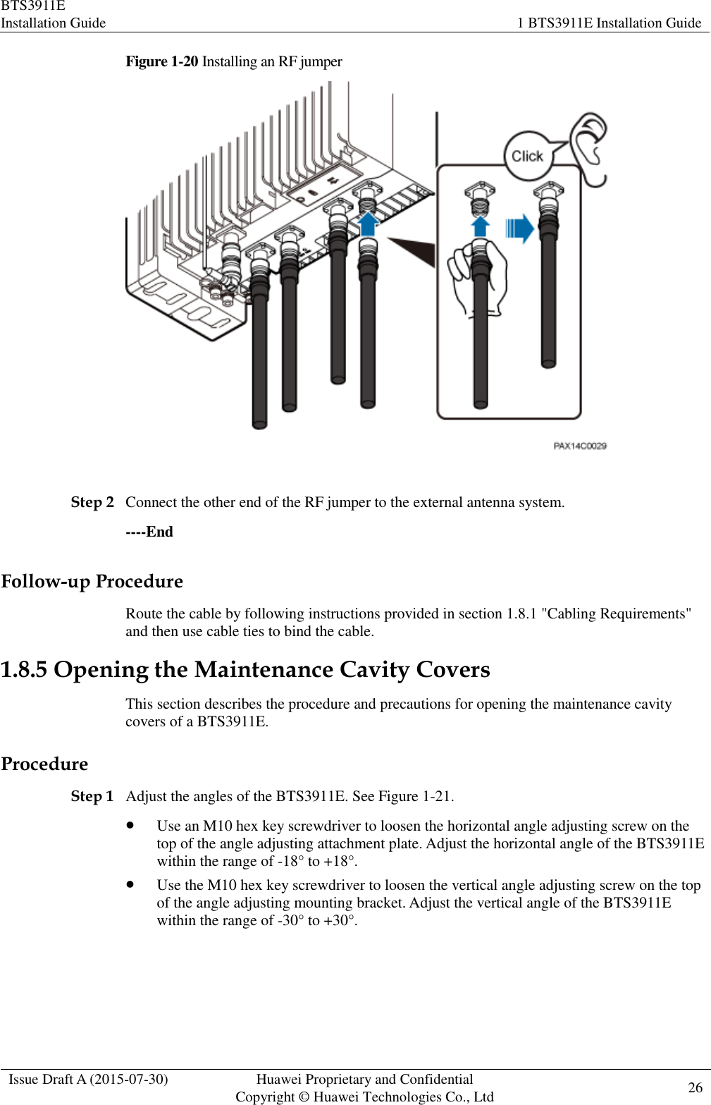
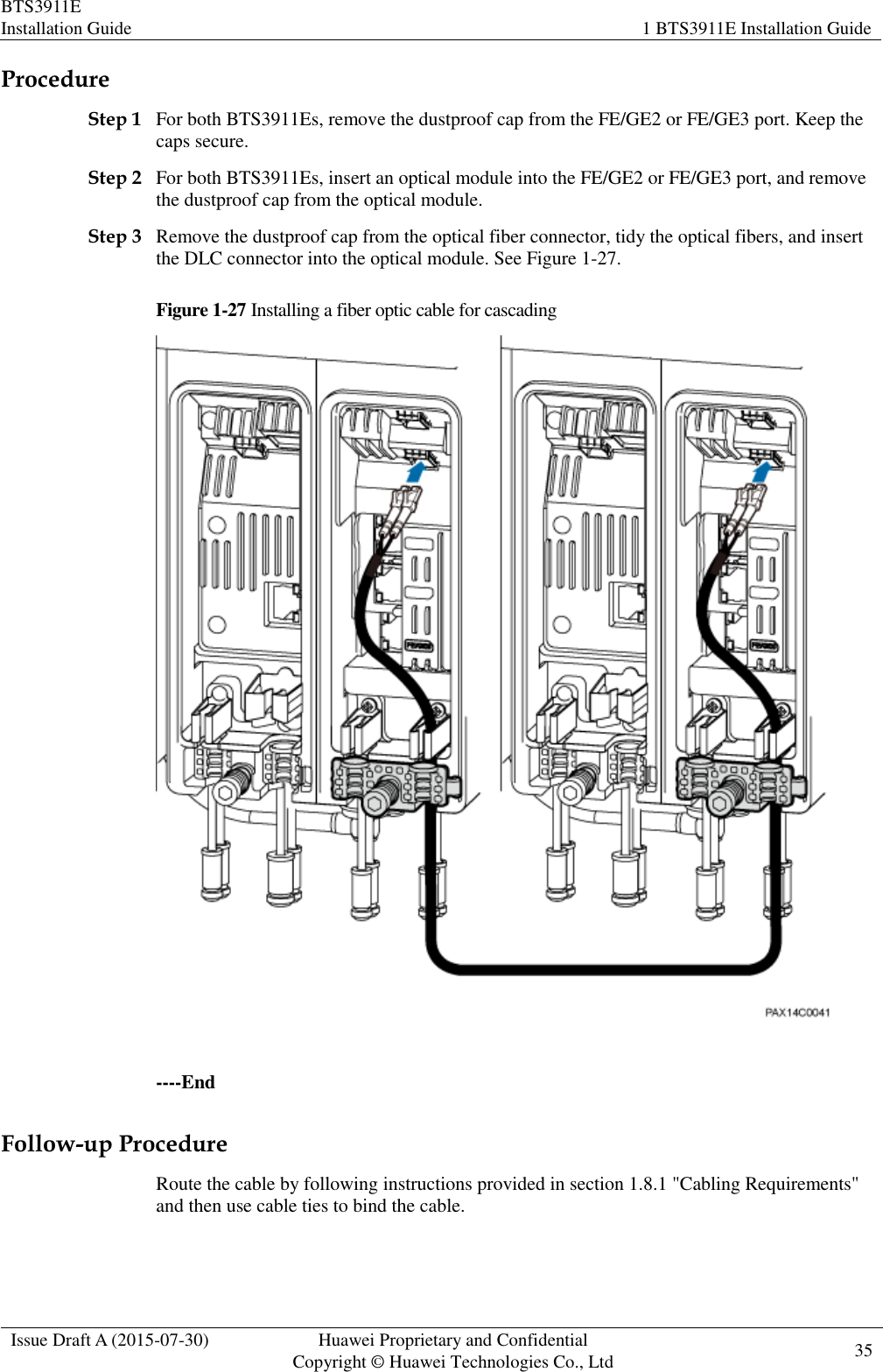
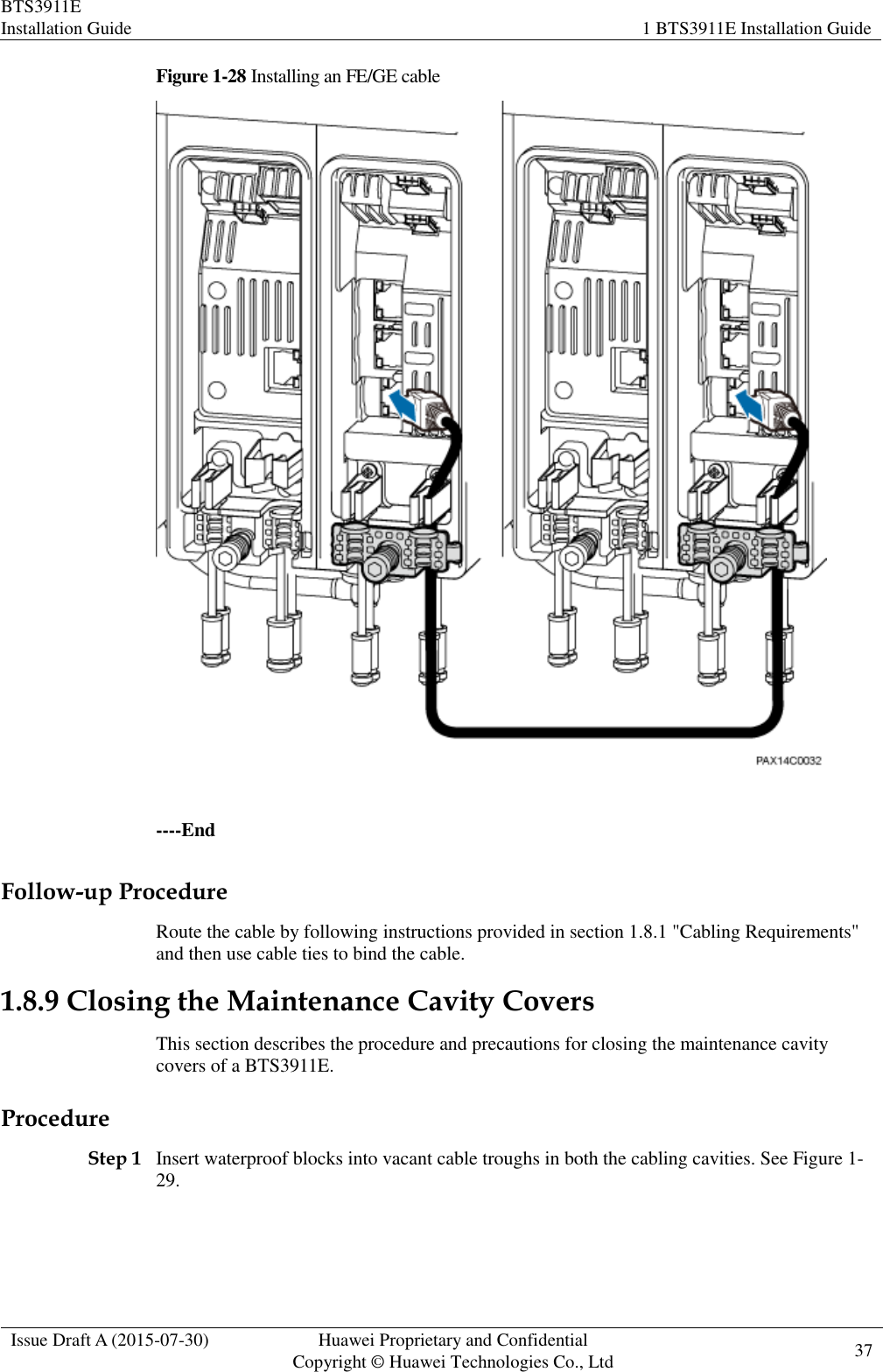
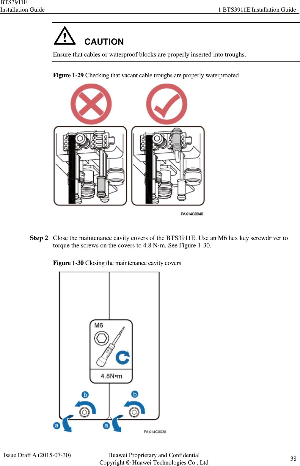
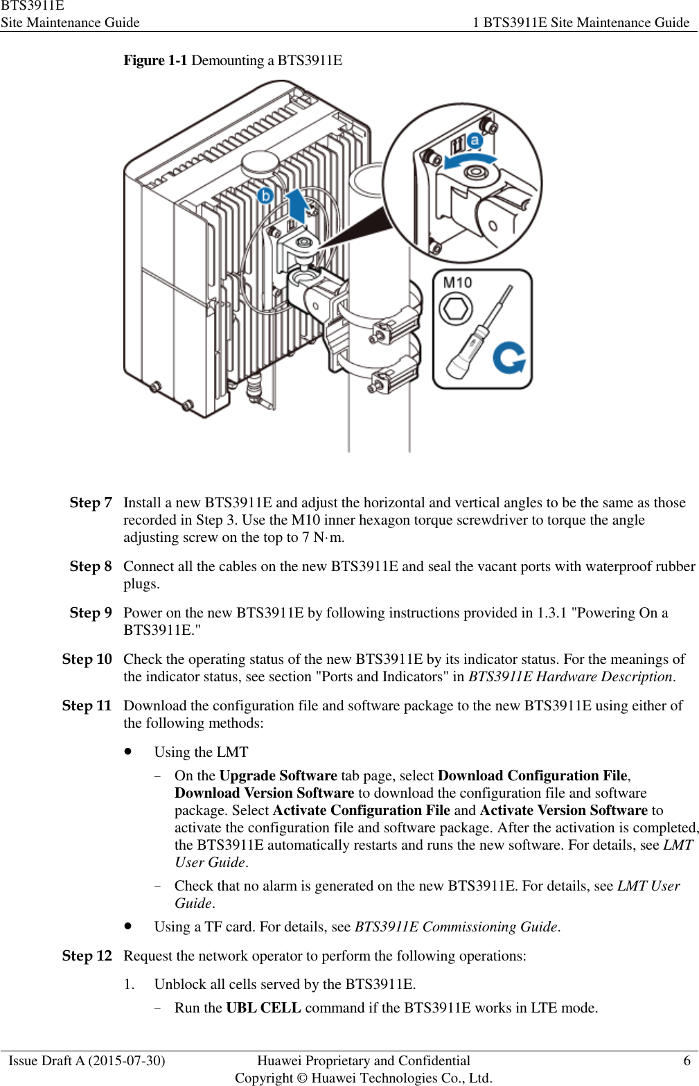
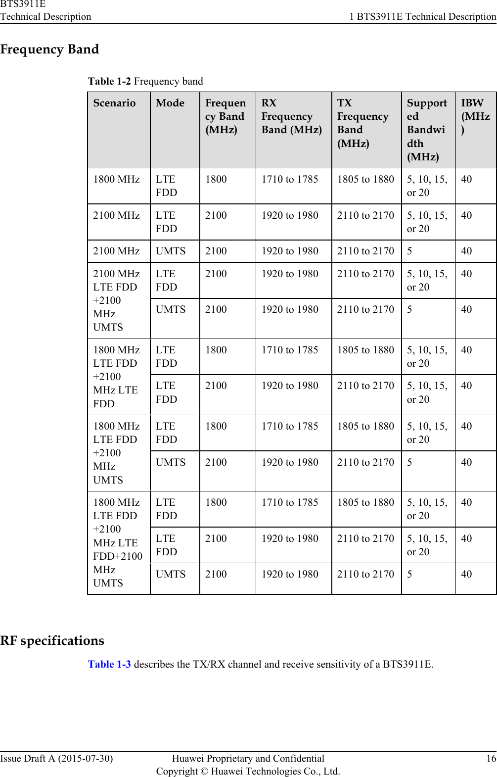
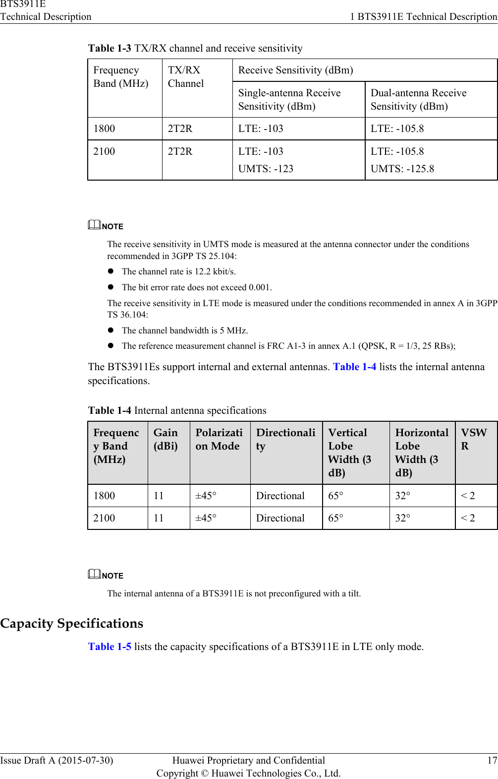
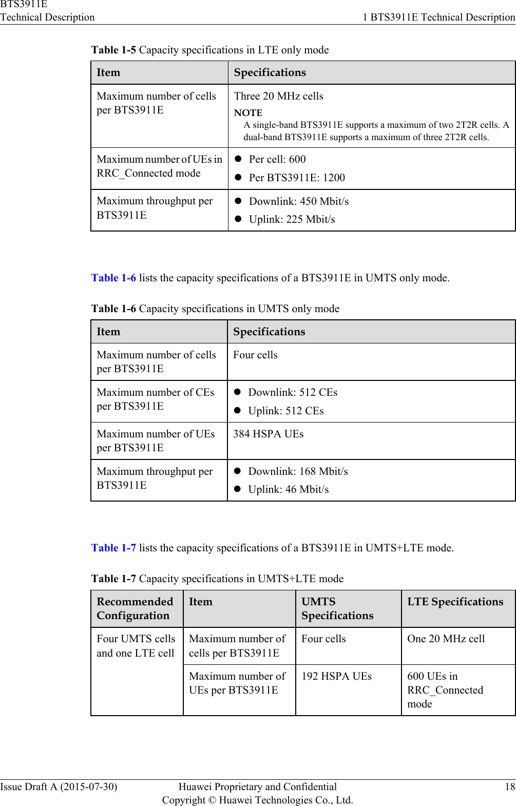
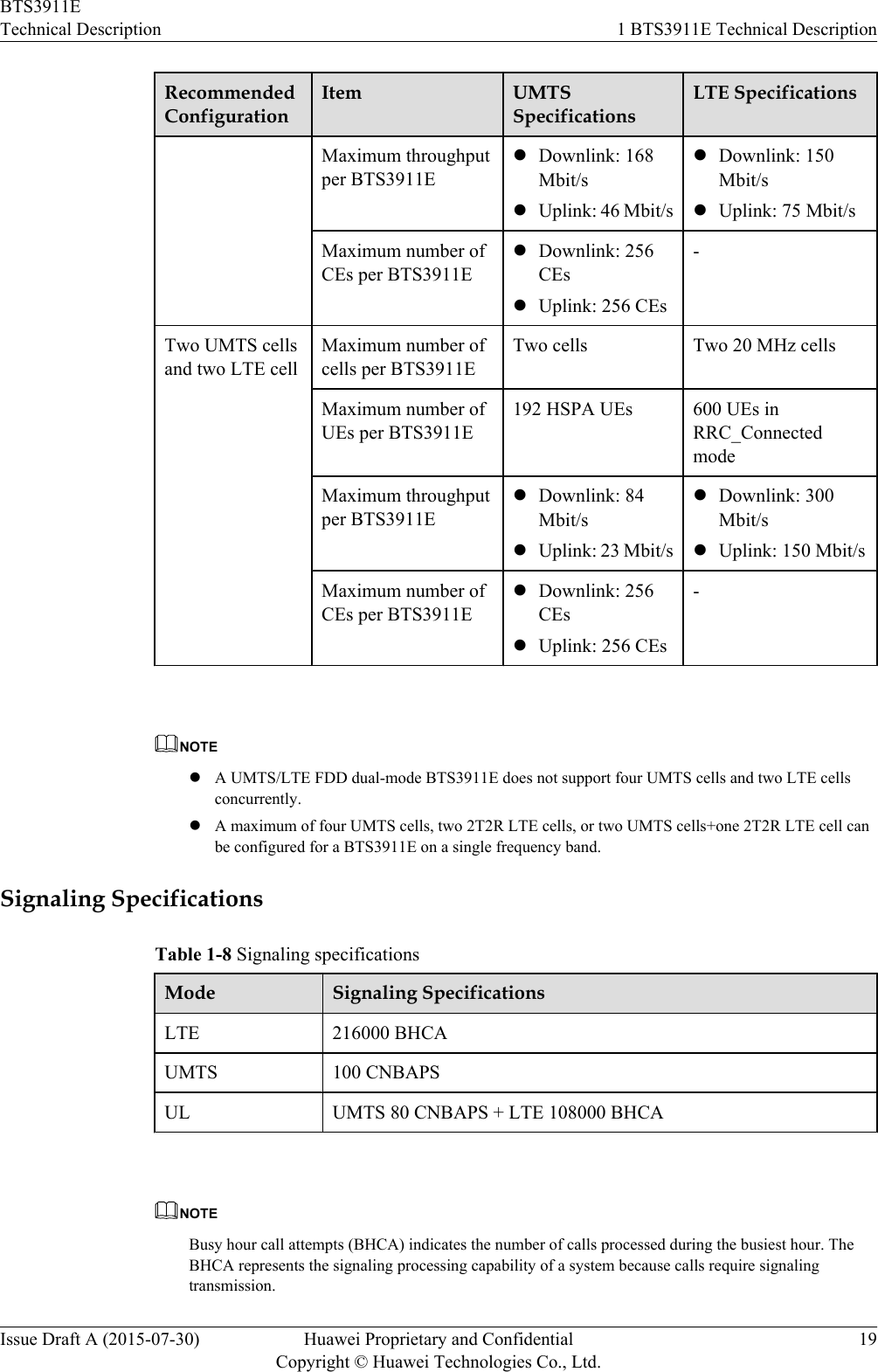
BTS3911E User Manual
UserManual.pdf
Navigation menu
Upload a User Manual
Namespaces
Wiki Guide
HTML
PDF
Info
Views
User Manual
Discussion / Help
Navigation