Huawei Technologies BTS3911E Micro BTS User Manual UserManual
Huawei Technologies Co.,Ltd Micro BTS UserManual
UserManual.pdf

Regulatory Compliance Statement
BTS3911E
Issue: 01
Date:2015-7-6
HUAWEI TECHNOLOGIES CO., LTD.

Issue (01)
Huawei Proprietary and Confidential
Copyright © Huawei Technologies Co., Ltd.
i
Copyright © Huawei Technologies Co., Ltd. 2010. All rights reserved.
No part of this document may be reproduced or transmitted in any form or by any means without prior written
consent of Huawei Technologies Co., Ltd.
Trademarks and Permissions
and other Huawei trademarks are trademarks of Huawei Technologies Co., Ltd.
All other trademarks and trade names mentioned in this document are the property of their respective holders.
Notice
The purchased products, services and features are stipulated by the contract made between Huawei and the customer.
All or part of the products, services and features described in this document may not be within the purchase scope or
the usage scope. Unless otherwise specified in the contract, all statements, information, and recommendations in this
document are provided "AS IS" without warranties, guarantees or representations of any kind, either express or
implied.
The information in this document is subject to change without notice. Every effort has been made in the preparation
of this document to ensure accuracy of the contents, but all statements, information, and recommendations in this
document do not constitute the warranty of any kind, express or implied.
Huawei Technologies Co., Ltd.
Address:
Huawei Industrial Base
Bantian, Longgang
Shenzhen 518129
People's Republic of China
Website:
http://www.huawei.com
Email:
support@huawei.com

1 Regulatory Compliance Statement
Issue (01)
Huawei Proprietary and Confidential
Copyright © Huawei Technologies Co., Ltd.
1-1
1 Regulatory Compliance Statement
About This Chapter
1.1 Declaration of Conformity to European Directives
1.1 Declaration of Conformity to European Directives
Figure 1-1 Declaration of Conformity to European Directives
None

2 Regulatory Compliance Information
Issue (01)
Huawei Proprietary and Confidential
Copyright © Huawei Technologies Co., Ltd.
2-1
2 Regulatory Compliance Information
About This Chapter
2.1 Regulatory Compliance Standards
2.2 European Regulatory Compliance
2.3 U.S.A Regulatory Compliance
2.4 Canada Regulatory Compliance
2.5 Japanese Regulatory Compliance
2.6 CISPR 22 Compliance
2.7 China RoHS hazardous substance table
2.8 India RoHS hazardous substance table
2.9 Other Markets
2.1 Regulatory Compliance Standards
Product complies with the standards listed in Table 2-1.

2 Regulatory Compliance Information
2-2
Huawei Proprietary and Confidential
Copyright © Huawei Technologies Co., Ltd.
Issue (01)
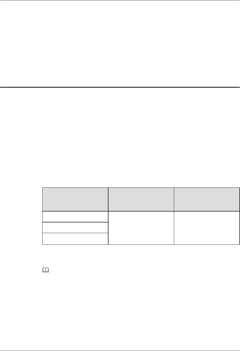
Table 2-1 Regulatory compliance standards
Discipline
Standards
EMC
CISPR22 Class B
CISPR24
EN55022 Class B
EN50024
ETSI EN 301 489 Class B
CFR 47 FCC Part 15 Class B
FCC Part 2
FCC Part 22
FCC Part 24
ICES 003 Class B/Class A
AS/NZS CISPR22 Class B
GB9254 Class B
VCCI Class B
CNS 13438 Class B
IEC61000-6-1
IEC61000-6-3
EN61000-6-1
EN61000-6-3
Safety
IEC 60950-1
IEC60950-22
IEC/EN60215
IEC/EN41003
EN 60950-1
UL 60950-1
CSA C22.2 No 60950-1
AS/NZS 60950.1
BS EN 60950-1
IS 13252
GB4943
Laser safety
FDA rules, 21 CFR 1040.10 and 1040.11
IEC60825-1, IEC60825-2, EN60825-1,
EN60825-2
GB7247

2 Regulatory Compliance Information
Issue (01)
Huawei Proprietary and Confidential
Copyright © Huawei Technologies Co., Ltd.
2-3
Discipline
Standards
RF
ETSI EN 301 908
ETSI EN 300 328
ETSI EN 301 893
FCC Part 2
FCC Part 24
FCC Part 27
RSS-133
RSS-139
Health
ICNIRP Guideline
1999-519-EC
EN 50385
OET Bulletin 65
FCC Part 1
IEEE Std C95.1
EN 60215
RSS-102
Environmental protection
2011/65/EU (RoHS)
EC NO. 1907/2006 (REACH)
2002/96/EC (WEEE)
Grounding
ITU-T K.27
ETSI EN 300 253

2 Regulatory Compliance Information
2-4
Huawei Proprietary and Confidential
Copyright © Huawei Technologies Co., Ltd.
Issue (01)
Discipline
Standards
NOTE
EMC: electromagnetic compatibility
NEBS: Network Equipment Build Standard
RF: radio frequency
CISPR: International Special Committee on Radio Interference
EN: European Standard
ETSI: European Telecommunications Standards Institute
CFR: Code of Federal Regulations
FCC: Federal Communication Commission
IEC: International Electrotechnical Commission
AS/NZS: Australian/New Zealand Standard
VCCI: Voluntary Control Council for Interference
CNS: Chinese National Standard
UL: Underwriters Laboratories
CSA: Canadian Standards Association
BS: British Standard
IS: Indian Standard
GR: General Requirement
FDA: Food and Drug Administration
BTS: Base Transceiver Station
GSM: Global System for Mobile communications
WLAN: wireless local area network
ICNIRP: International Commission on Non-Ionizing Radiation Protection
OET: Office of Engineering Technology
IEEE: Institute of Electrical and Electronics Engineers
RoHS: restriction of the use of certain hazardous substances
2.2 European Regulatory Compliance
Product complies with the following European directives and regulations.
2004/108/EC (EMC)
2006/95/EC (low voltage)
1999/5/EC (R&TTE)
2011/65/EU (RoHS)
EC NO. 1907/2006 (REACH)
2002/96/EC (WEEE)
Product complies with Directive 2002/95/EC, 2011/65/EU and other similar regulations from
the countries outside the European Union, on the RoHS in electrical and electronic equipment.
The device does not contain lead, mercury, cadmium, and hexavalent chromium and
brominated flame retardants (Polybrominated Biphenyls (PBB) or Polybrominated Diphenyl
Ethers (PBDE)) except for those exempted applications allowed by RoHS directive for
technical reasons.
2 Regulatory Compliance Information
Issue (01)
Huawei Proprietary and Confidential
Copyright © Huawei Technologies Co., Ltd.
2-5
Product complies with Regulation EC NO. 1907/2006 (REACH) and other similar regulations
from the countries outside the European Union. Huawei will notify to the European Chemical
Agency (ECHA) or the customer when necessary and regulation requires.
Product complies with Directive 2002/96/EC on waste electrical and electronic equipment
(WEEE). Huawei is responsible for recycling its end-of-life devices, and please contact
Huawei local service center when recycling is required. Huawei strictly complies with the EU
Waste Electrical and Electronic Equipment Directive (WEEE Directive) and electronic waste
management regulations enacted by different countries worldwide. In addition, Huawei has
established a system for recycling and reuse of electronic wastes, and it can provide service of
dismantling and recycling for WEEE. By Huawei recycling system, the waste can be handled
environmentally and the resource can be recycled and reused fully, which is also Huawei
WEEE stratagem in the word. Most of the materials in product are recyclable, and our
packaging is designed to be recycled and should be handled in accordance with your local
recycling policies.
In accordance with Article 11(2) in Directive 2002/96/EC (WEEE), products were marked
with the following symbol: a cross-out wheeled waste bin with a bar beneath as below:
In order to avoid the possibility of exceeding the Europe radio frequency exposure limits,
human proximity to the equipment shall not be less than 0.124 m
2.3 U.S.A Regulatory Compliance
2.3.1 Safety compliance Mark
2.3.2 FCC
2.3.1 Safety compliance Mark

2 Regulatory Compliance Information
2-6
Huawei Proprietary and Confidential
Copyright © Huawei Technologies Co., Ltd.
Issue (01)
2.3.2FCC
Product complies with Part 15 of the FCC Rules. Operation is subject to the following two
conditions:
This device does not cause harmful interference.
This device must accept any interference received, including interference that may cause
undesired operation.
If this device is modified without authorization from Huawei, the device may no longer
comply with FCC requirements for Class B digital devices. In that a case, your right to use the
device may be limited by FCC regulations. Moreover, you may be required to correct any
interference to radio or television communications at your own expense.
This device has been tested and found to comply with the limits for a Class B digital device,
pursuant to Part 15 of the FCC rules. These limits are designed to provide reasonable
protection against harmful interference in a residential installation.
This device generates, uses and radiates radio frequency energy. If it is not installed and used
in accordance with the instructions, it may cause harmful interference to radio
communications.
However, there is no guarantee that interference will not occur in a particular installation. If
this device does cause harmful interference to radio or television reception, which can be
determined by turning the device off and on, the user may take one or more of the following
measures:
Reorient or relocate the receiving antenna.
Reinforce the separation between the device and receiver.
Connect the device into an outlet on a circuit different from that to which the receiver is
connected.
Consult the dealer or an experienced radio or TV technician for assistance.
In order to avoid the possibility of exceeding the 47CFR FCC Part 1 & OET Bulletin 65
radio frequency exposure limits, human proximity to the equipment shall not be less than
1.78 m
2.4 Canada Regulatory Compliance
2.4.1 RSS-Gen statement
This device complies with Industry Canada licence-exempt RSS standard(s).

2 Regulatory Compliance Information
Issue (01)
Huawei Proprietary and Confidential
Copyright © Huawei Technologies Co., Ltd.
2-7
Operation is subject to the following two conditions: (1) this device may not cause
interference, and (2) this device must accept any interference, including interference that may
cause undesired operation of the device.
Le présent appareil est conforme aux CNR d'Industrie Canada applicables aux appareils radio
exempts de licence. L'exploitation est autorisée aux deux conditions suivantes : (1) l'appareil
ne doit pas produire de brouillage, et (2) l'utilisateur de l'appareil doit accepter tout brouillage
radioélectrique subi, même si le brouillage est susceptible d'en compromettre le
fonctionnement.
2.4.2 RSS-102 statement
This device is designed and manufactured not to exceed the emission limits for exposure to
radio frequency (RF) energy set by Industrial Canada and meets the requirements for radiation
exposure limits set forth for an uncontrolled environment.
In order to avoid the possibility of exceeding the Industrial Canada radio frequency exposure
limits, human proximity to the equipment shall not be less than 2.58 m
Cet appareil est conçu et fabriqué pour ne pas dépasser les limites d'émission pour l'exposition
à la fréquence radio (RF) de l'énergie fixé par l'Industrielle Canada et répond aux exigences en
matière de limites d'exposition aux rayonnements définies pour un environnement non
contrôlé.
Afin d'éviter la possibilité de dépasser les limites d'exposition aux fréquences radio
industrielle du Canada, la proximité humaine pour l'appareil nedoit pas être inférieure à 2.58
m
2.5 Japanese Regulatory Compliance
2.5.1 VCCI
2.5.1VCCI
Product complies with VCCI Class B by Information Technology Equipment (ITE).
The preceding translates as follows:
This is a Class B product based on the standard of the Voluntary Control Council for
Interference by Information Technology Equipment (VCCI).If this product is used
Near a radio or television receiver in a domestic environment. It may cause radio
Interference.Install and use the equipment according to the instruction manual.

2 Regulatory Compliance Information
2-8
Huawei Proprietary and Confidential
Copyright © Huawei Technologies Co., Ltd.
Issue (01)
2.6 CISPR 22 Compliance
Product complies with CISPR 22 for Class B by the ITE.
2.7 China RoHS hazardous substance table
This products described in this guide complies with “the Administration on the Control of Pollution Caused by
Electronic Information Products” which is also called China RoHS
部件名称
产品中有害物质或元素的名称及含量
镉
铅
汞
六价铬
多溴联苯
多溴联苯醚
Frame
〇
╳
〇
〇
〇
〇
Alloy Parts
〇
╳
〇
〇
〇
〇
Power Adapter
〇
╳
〇
〇
〇
〇
Metal Fittings
〇
〇
〇
〇
〇
〇
PCBA
〇
╳
〇
〇
〇
〇
Capacitor
〇
╳
〇
〇
〇
〇
Other electronics
〇
╳
〇
〇
〇
〇
Screen
〇
〇
〇
〇
〇
〇
Solder
〇
╳
〇
〇
〇
〇
Cable
╳
╳
〇
〇
〇
〇
Plastic and Polymer
〇
╳
〇
〇
〇
╳
Label
〇
〇
〇
〇
〇
〇
Battery
〇
〇
〇
〇
〇
〇
〇:表示该有毒有害物质在该部件所有均质材料中的含量均在SJ/T11363-2006 标准规定的限量要求以下。

2 Regulatory Compliance Information
Issue (01)
Huawei Proprietary and Confidential
Copyright © Huawei Technologies Co., Ltd.
2-9
╳:表示该有毒有害物质至少在该部件的某一均质材料中的含量超出SJ/T11363-2006 标准规定的限量要
求。
2.8 India RoHS hazardous substance table
This products described in this guide complies with the “e-waste (Management and Handling) Rules, 2011”of
India which is also called India RoHS.
Part Descriptions
Restricted Substances in Product
Cd
Pb
Hg
Cr(VI)
PBBs
PBDEs
Frame
〇
╳
〇
〇
〇
〇
Alloy Parts
〇
╳
〇
〇
〇
〇
Power Adapter
〇
╳
〇
〇
〇
〇
Metal Fittings
〇
〇
〇
〇
〇
〇
PCBA
〇
╳
〇
〇
〇
〇
Capacitor
〇
╳
〇
〇
〇
〇
Other electronics
〇
╳
〇
〇
〇
〇
Screen
〇
〇
〇
〇
〇
〇
Solder
〇
╳
〇
〇
〇
〇
Cable
╳
╳
〇
〇
〇
〇
Plastic and Polymer
〇
╳
〇
〇
〇
╳
Label
〇
〇
〇
〇
〇
〇
Battery
〇
〇
〇
〇
〇
〇
〇: indicates that the content of the toxic and hazardous substance in all the Homogeneous Materials of the part is
below the concentration limit requirement as described in the e-waste (Management and Handling) Rules, 2011.
╳: indicates that the content of the toxic and hazardous substance in at least one Homogeneous Material of the

2 Regulatory Compliance Information
2-10
Huawei Proprietary and Confidential
Copyright © Huawei Technologies Co., Ltd.
Issue (01)
part exceeds the concentration limit requirement as described in S in the e-waste (Management and Handling)
Rules, 2011.
2.9 Other Markets
For relevant compliance information/documentation for markets not mentioned above,
please contact Huawei representative

BTS3911E
V100R011C00
Hardware Description
Issue Draft A
Date 2015-07-30
HUAWEI TECHNOLOGIES CO., LTD.

Copyright © Huawei Technologies Co., Ltd. 2015. All rights reserved.
No part of this document may be reproduced or transmitted in any form or by any means without prior written
consent of Huawei Technologies Co., Ltd.
Trademarks and Permissions
and other Huawei trademarks are trademarks of Huawei Technologies Co., Ltd.
All other trademarks and trade names mentioned in this document are the property of their respective holders.
Notice
The purchased products, services and features are stipulated by the contract made between Huawei and the
customer. All or part of the products, services and features described in this document may not be within the
purchase scope or the usage scope. Unless otherwise specified in the contract, all statements, information,
and recommendations in this document are provided "AS IS" without warranties, guarantees or representations
of any kind, either express or implied.
The information in this document is subject to change without notice. Every effort has been made in the
preparation of this document to ensure accuracy of the contents, but all statements, information, and
recommendations in this document do not constitute a warranty of any kind, express or implied.
Huawei Technologies Co., Ltd.
Address: Huawei Industrial Base
Bantian, Longgang
Shenzhen 518129
People's Republic of China
Website: http://www.huawei.com
Email: support@huawei.com
Issue Draft A (2015-07-30) Huawei Proprietary and Confidential
Copyright © Huawei Technologies Co., Ltd.
i

Contents
1 About This Document..................................................................................................................1
2 Changes in BTS3911E Hardware Description..........................................................................2
3 BTS3911E Equipment...................................................................................................................3
3.1 Appearance.....................................................................................................................................................................4
3.2 Ports and Indicators........................................................................................................................................................5
4 BTS3911E Cables...........................................................................................................................9
4.1 Cable List......................................................................................................................................................................10
4.2 PGND Cable.................................................................................................................................................................11
4.3 Power Cable..................................................................................................................................................................11
4.4 FE/GE Ethernet Cable..................................................................................................................................................12
4.5 FE/GE Fiber Optic Cable.............................................................................................................................................14
4.6 Alarm Cable..................................................................................................................................................................16
4.7 (Optional) RF Jumper...................................................................................................................................................17
5 (Optional) GPS Antenna............................................................................................................18
6 Typical Networking and Cable Connection..........................................................................20
6.1 Typical Networking......................................................................................................................................................21
6.2 Cable Connection Principles........................................................................................................................................22
7 Power Requirements...................................................................................................................23
8 Engineering Specifications........................................................................................................24
BTS3911E
Hardware Description Contents
Issue Draft A (2015-07-30) Huawei Proprietary and Confidential
Copyright © Huawei Technologies Co., Ltd.
ii
1 About This Document
Introduction
This document describes the BTS3911E and related information, such as networking, cables,
cable connections, and specifications, to provide guidelines for planning and deploying the
BTS3911E.
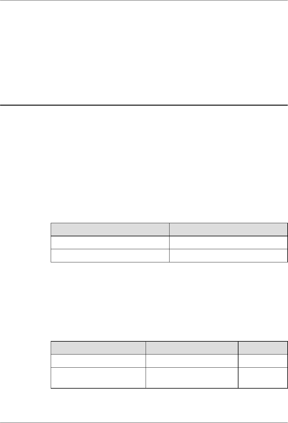
Product Version
The following table lists the product versions related to this document.
Product Name Solution Version Product Version
BTS3911E lSRAN11.0
lRAN18.0
leRAN11.0
V100R011C00
Intended Audience
This document is intended for:
lBTS3911E installation engineers
lSystem engineers
lSite maintenance engineers
BTS3911E
Hardware Description 1 About This Document
Issue Draft A (2015-07-30) Huawei Proprietary and Confidential
Copyright © Huawei Technologies Co., Ltd.
1

2 Changes in BTS3911E Hardware Description
This section describes the changes in BTS3911E Hardware Description.
Draft A (2015-07-30)
This is a draft.
BTS3911E
Hardware Description 2 Changes in BTS3911E Hardware Description
Issue Draft A (2015-07-30) Huawei Proprietary and Confidential
Copyright © Huawei Technologies Co., Ltd.
2

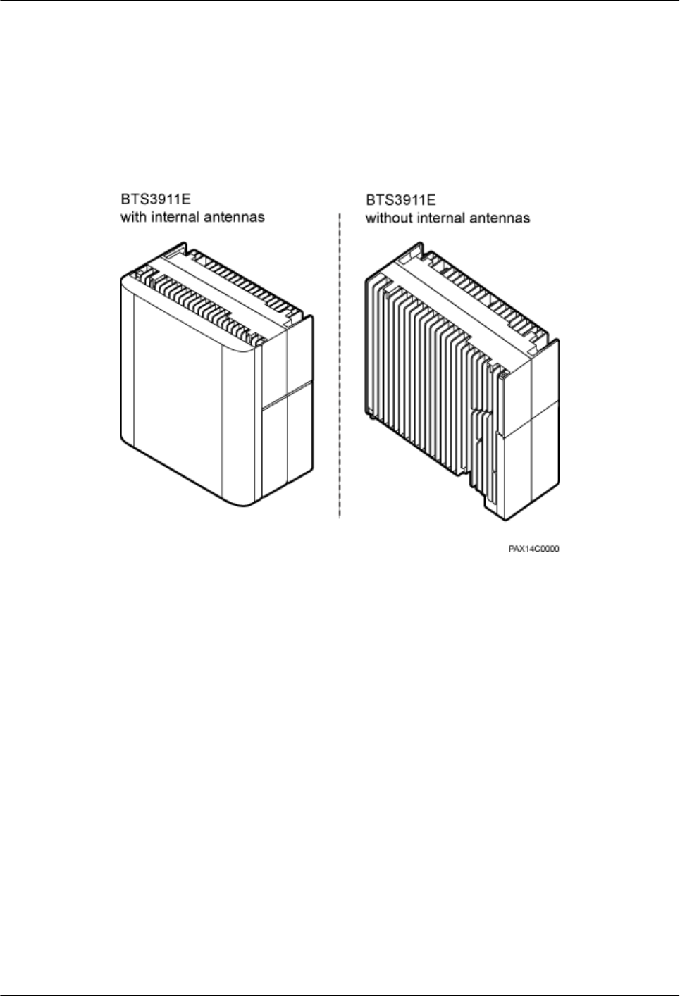
3.1 Appearance
This section describes the appearance and dimensions of a BTS3911E.
Figure 3-1 shows the appearance of BTS3911E.
Figure 3-1 BTS3911E appearance
Figure 3-2 shows its dimensions.
BTS3911E
Hardware Description 3 BTS3911E Equipment
Issue Draft A (2015-07-30) Huawei Proprietary and Confidential
Copyright © Huawei Technologies Co., Ltd.
4
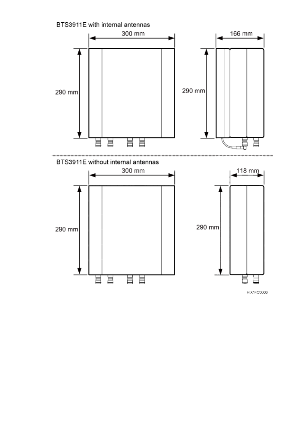
Figure 3-2 BTS3911E dimensions
3.2 Ports and Indicators
This section describes the BTS3911E ports (on the bottom or the side maintenance cavity) and
indicators (on the bottom).
Positions
Figure 3-3 shows the positions of the BTS3911E ports and indicators.
BTS3911E
Hardware Description 3 BTS3911E Equipment
Issue Draft A (2015-07-30) Huawei Proprietary and Confidential
Copyright © Huawei Technologies Co., Ltd.
5
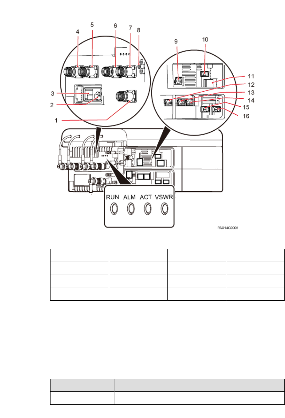
Figure 3-3 Positions of the BTS3911E ports and indicators
(1) GPS (2) TF card (3) USB WIFI (4) ANT D
(5) ANT C (6) ANT B (7) ANT A (8) Ground terminal
(9) EXT_ALM (10) CPRI (11) PWR (12) FE/GE0
(13) FE/GE1 (14) DBG (15) FE/GE2 (16) FE/GE3
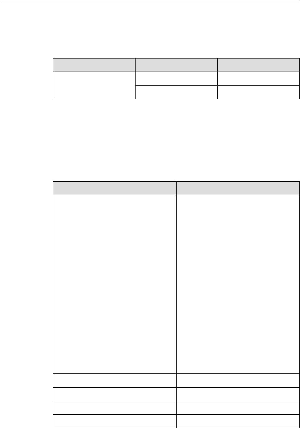
Ports
Table 3-1 describes the BTS3911E ports.
Table 3-1 BTS3911E ports
Port Description
PWR Power input port
BTS3911E
Hardware Description 3 BTS3911E Equipment
Issue Draft A (2015-07-30) Huawei Proprietary and Confidential
Copyright © Huawei Technologies Co., Ltd.
6
Port Description
CPRI Reserved port
EXT-ALM Dry contact alarm port for monitoring the alarm status of external
devices
TF Anchor slot for the trans flash card (TF card, also called micro SD
card) for BTS3911E deployment
DBG Commissioning port
FE/GE0 Electrical port
FE/GE1 Electrical port
FE/GE2 Optical port
FE/GE3 Optical port
ANT A Port A used to transmit and receive RF signals
ANT B Port B used to transmit and receive RF signals
ANT C Port C used to transmit and receive RF signals
ANT D Port D used to transmit and receive RF signals
GPS Port for connecting GPS antennas to achieve clock synchronization
USB WIFI Wi-Fi port for zero-touch maintenance and deployment
Ground terminal
Indicators
A BTS3911E has four indicators. Table 3-2 describes the indicators.
NOTE
The BTS3911E indicators can be turned on or off by following instructions provided in BTS3911E Site
Maintenance Guide.
Table 3-2 BTS3911E indicators
Indicator Meaning Status Description
RUN Operating status Steady green There is power supply, but
the BTS3911E is faulty.
Off There is no power supply, or
the BTS3911E is faulty.
BTS3911E
Hardware Description 3 BTS3911E Equipment
Issue Draft A (2015-07-30) Huawei Proprietary and Confidential
Copyright © Huawei Technologies Co., Ltd.
7

Indicator Meaning Status Description
Blinking green (on for 1s
and off for 1s)
The BTS3911E is running
properly.
Blinking green (on for
0.125s and off for
0.125s)
Software is being loaded to
the BTS3911E, or the
BTS3911E is not started.
ALM Alarm status Steady red Alarms are generated, and
the BTS3911E must be
replaced.
Blinking red (on for 1s
and off for 1s)
An alarm is generated. The
alarm may be caused by
faults in related modules or
ports. Therefore, the
necessity for BTS3911E
replacement is uncertain.
Off No alarm is generated.
ACT Service status Steady green The BTS3911E is activated
and working properly.
Off The BTS3911E is
deactivated or is not
running.
Blinking green (on for
0.125s and off for
0.125s)
The operation and
maintenance link (OML) is
disconnected.
Blinking green (on for 2s
and off for 2s)
Services are not available,
for example, the cells or
service links are not ready
for service provisioning.
Blinking green (on for 1s
and off for 1s)
The BTS3911E is being
tested, for example, in an
RRU VSWR test by using a
USB flash drive.
VSWR VSWR alarm status Steady red A VSWR alarm is
generated, and the
BTS3911E may be
replaced.
Off No VSWR alarm is
generated.
BTS3911E
Hardware Description 3 BTS3911E Equipment
Issue Draft A (2015-07-30) Huawei Proprietary and Confidential
Copyright © Huawei Technologies Co., Ltd.
8

4 BTS3911E Cables
This section describes the appearance, core wire types, and installation positions of BTS3911E
cables.
4.1 Cable List
4.2 PGND Cable
4.3 Power Cable
4.4 FE/GE Ethernet Cable
4.5 FE/GE Fiber Optic Cable
4.6 Alarm Cable
4.7 (Optional) RF Jumper
BTS3911E
Hardware Description 4 BTS3911E Cables
Issue Draft A (2015-07-30) Huawei Proprietary and Confidential
Copyright © Huawei Technologies Co., Ltd.
9

4.1 Cable List
This section describes the connection positions and connector types of BTS3911E cables.
BTS3911E cables include PGND cables, power cables, transmission cables, RF jumpers, GPS
signal cables, and alarm cables, as listed in Table 4-1.
Table 4-1 BTS3911E cable list
Cable One End The Other End
Connector Installation
Position
(Equipment/
Module/Port)
Connector Installation Position
(Equipment/
Module/Port)
4.2 PGND
Cable
OT terminal
(M6, 6 mm2)
Ground terminal
of the BTS3911E
OT terminal
(M8, 6 mm2)
External ground bar
4.3 Power
Cable
Tool-less
female
connector
AC-EPC1
(pressfit
type)
PWR port on the
BTS3911E
maintenance
cavity
Depends on the
external power
supply
equipment.
External power
supply equipment
4.4 FE/GE
Ethernet
Cable
RJ45
connector
FE/GE0 or FE/
GE1 port on the
BTS3911E
maintenance
cavity
RJ45 connector External
transmission
equipment
RJ45 connector FE/GE0 or FE/GE1
port on the
BTS3911E
maintenance cavity
4.5 FE/GE
Fiber Optic
Cable
DLC
connector
FE/GE2 or FE/
GE3 port on the
BTS3911E
maintenance
cavity
FC, LC, or SC
connector
External
transmission
equipment
DLC connector FE/GE2 or FE/GE3
port on the
BTS3911E
maintenance cavity
4.6 Alarm
Cable
RJ45
connector
EXT-ALM port
on the BTS3911E
maintenance
cavity
Depends on the
external
monitored
equipment
External monitored
equipment
BTS3911E
Hardware Description 4 BTS3911E Cables
Issue Draft A (2015-07-30) Huawei Proprietary and Confidential
Copyright © Huawei Technologies Co., Ltd.
10
4.7
(Optional)
RF Jumper
Smart-type N
male
connector
ANT A, ANT B,
ANT C, or ANT D
port on the
BTS3911E
Type N male
connector
External antenna
system
4.2 PGND Cable
A PGND cable connects the ground terminal of a BTS3911E to a ground bar, providing ground
protection for the BTS3911E.
Appearance
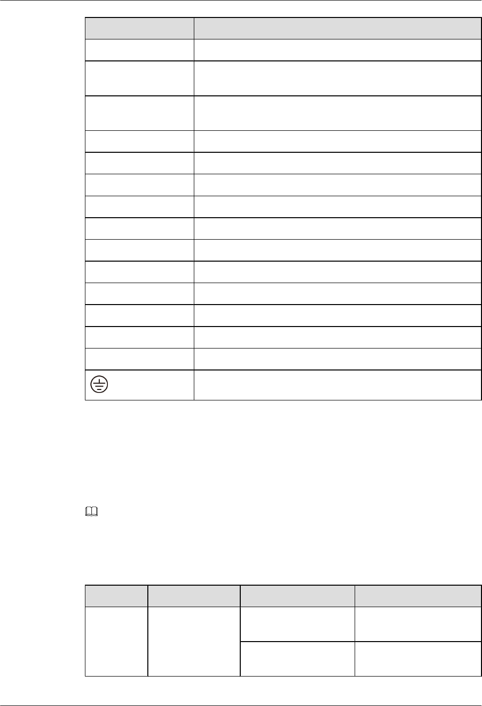
Figure 4-1 shows the appearance of a PGND cable with connectors.
Figure 4-1 PGND cable appearance
(1) OT terminal
Cable Description
Table 4-2 describes the BTS3911E PGND cable.
Table 4-2 PGND cable description
Cable One End The Other End Color
PGND cable OT terminal (M6, 6
mm2)
OT terminal (M8, 6
mm2)
Yellow and green or
green
4.3 Power Cable
A power cable connects the BTS3911E to the external AC power supply equipment.
BTS3911E
Hardware Description 4 BTS3911E Cables
Issue Draft A (2015-07-30) Huawei Proprietary and Confidential
Copyright © Huawei Technologies Co., Ltd.
11
Appearance
A tool-less female connector (pressfit type) needs to be added to one end of a BTS3911E power
cable onsite. A corresponding terminal needs to be added to the other end based on the port on
the external power supply equipment. Figure 4-2 shows the appearance of a BTS3911E power
cable.
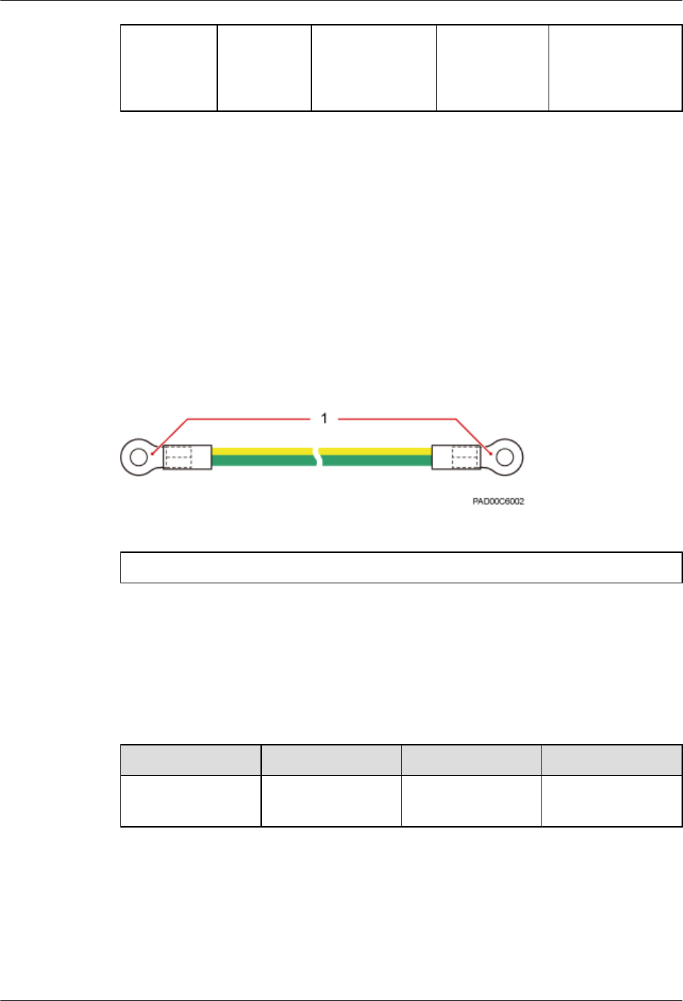
Figure 4-2 Power cable appearance
(1) Tool-less female connector (pressfit type)
Cable Description
Table 4-3 describes the BTS3911E power cable.
Table 4-3 Power cable description
Cable Core Wire Wire Color Cable
Specifications
Power cable L Brown 1.5 mm2 to 2.5 mm2
N Blue
PE Yellow and green
NOTE
The color and structure of a power cable varies with countries and regions. A locally purchased power
cable must be a pure copper outdoor three-core cable that has a cross-sectional area of 1.5 mm2 to 2.5
mm2 and a maximum outer diameter of 8.9 mm to 10.2 mm and complies with local specifications.
4.4 FE/GE Ethernet Cable
An FE/GE Ethernet cable transmits FE/GE signals between a BTS3911E and the external
transmission equipment or between two BTS3911Es.
BTS3911E
Hardware Description 4 BTS3911E Cables
Issue Draft A (2015-07-30) Huawei Proprietary and Confidential
Copyright © Huawei Technologies Co., Ltd.
12
NOTE
FE/GE Ethernet cables can be used for transmission over a maximum distance of 100 m.
Appearance
An FE/GE Ethernet cable is a Category 5e or above shielded foil twisted pair (SFTP) cable in
compliance with TIA/EIA-568B. It is terminated with an RJ45 connector at both ends.
NOTE
Ethernet cables of a higher level can also be used. For detailed specifications, see standards related to
Ethernet cables.
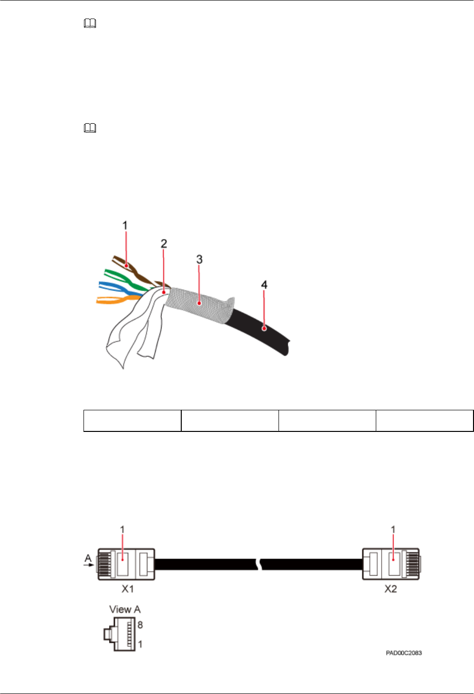
Figure 4-3 shows the structure of an FE/GE Ethernet cable.
Figure 4-3 Structure of an FE/GE Ethernet cable
(1) Core wire (2) Aluminum foil (3) Braided layer (4) Jacket
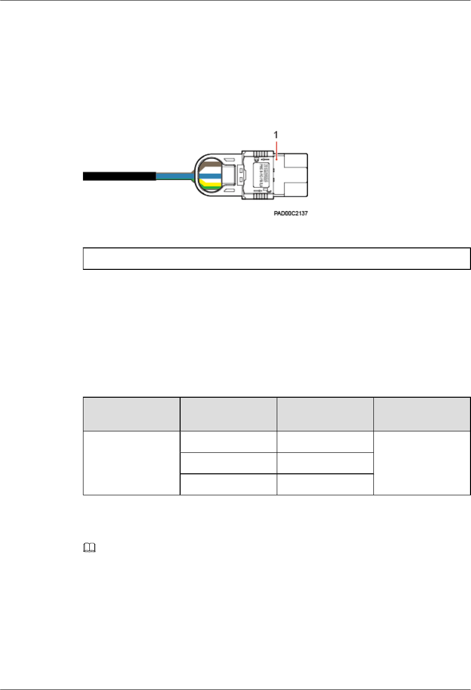
Figure 4-4 shows the appearance of an FE/GE Ethernet cable.
Figure 4-4 Appearance of an FE/GE Ethernet cable
BTS3911E
Hardware Description 4 BTS3911E Cables
Issue Draft A (2015-07-30) Huawei Proprietary and Confidential
Copyright © Huawei Technologies Co., Ltd.
13
(1) RJ45 connector
Cable Description
Table 4-4 describes the pin assignment of an FE/GE Ethernet cable.
Table 4-4 Pin assignment of an FE/GE Ethernet cable
Pin on the RJ45
Connector
Wire Color Wire Type Pin on the RJ45
Connector
X1.2 Orange Twisted pair X2.2
X1.1 White/orange X2.1
X1.6 Green Twisted pair X2.6
X1.3 White/green X2.3
X1.4 Blue Twisted pair X2.4
X1.5 White/blue X2.5
X1.8 Brown Twisted pair X2.8
X1.7 White/brown X2.7
4.5 FE/GE Fiber Optic Cable
An FE/GE fiber optic cable transmits optical signals between a BTS3911E and the external
transmission equipment or between two BTS3911Es.
NOTE
A standard fiber optic cable is 70 m long or shorter.
Connecting a BTS3911E and a Transmission Device
An FE/GE fiber optic cable connecting a BTS3911E and a transmission device has a DLC
connector at one end, and FC, LC, or SC connectors on the other end, as shown in Figure 4-5.
BTS3911E
Hardware Description 4 BTS3911E Cables
Issue Draft A (2015-07-30) Huawei Proprietary and Confidential
Copyright © Huawei Technologies Co., Ltd.
14
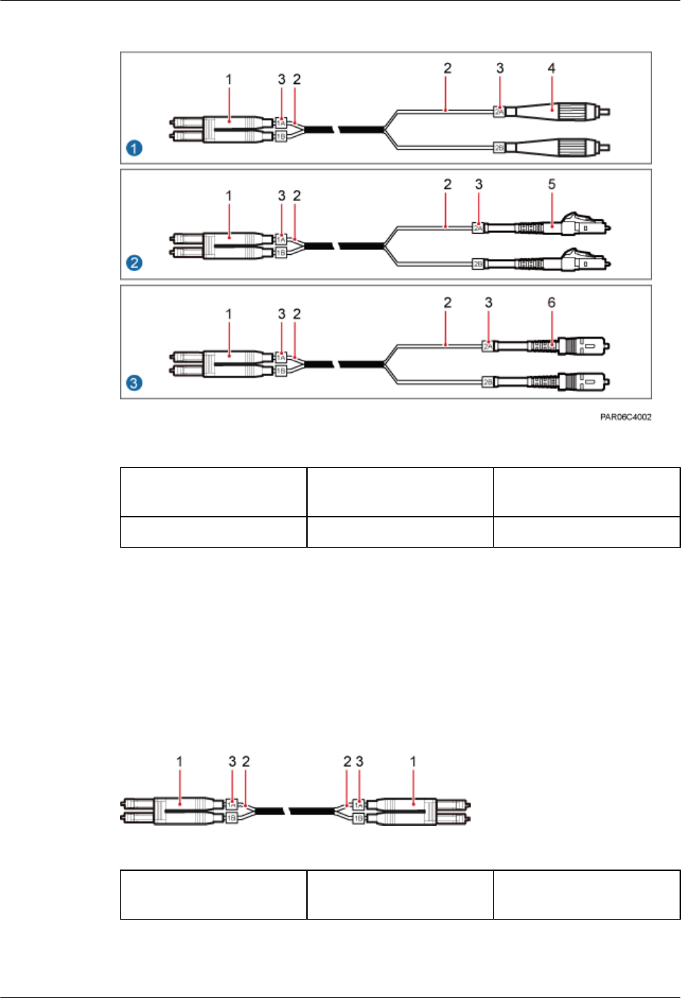
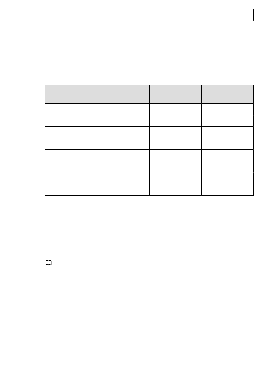
Figure 4-5 FE/GE fiber optic cable (1)
(1) DLC connector (2) Branch fiber optic cable (3) Branch fiber optic cable
label
(4) FC connector (5) LC connector (6) SC connector
Connecting Two BTS3911Es
An FE/GE fiber optic cable connecting two BTS3911Es has a DLC connector at each end, as
shown in Figure 4-6.
Figure 4-6 FE/GE fiber optic cable (2)
(1) DLC connector (2) Branch fiber optic cable (3) Branch fiber optic cable
label
BTS3911E
Hardware Description 4 BTS3911E Cables
Issue Draft A (2015-07-30) Huawei Proprietary and Confidential
Copyright © Huawei Technologies Co., Ltd.
15
4.6 Alarm Cable
An alarm cable transmits alarm signals from external devices to a BTS3911E so that the
BTS3911E can monitor the operating status of the external devices.
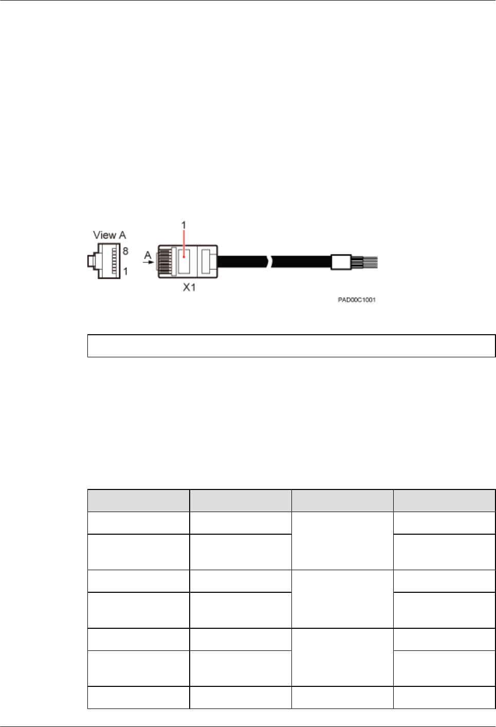
Appearance
An RJ45 connector needs to be added to one end of a BTS3911E alarm cable. A corresponding
terminal needs to be added to the other end based on the port on the external monitored
equipment. Figure 4-7 shows the appearance of a BTS3911E alarm cable.
Figure 4-7 Alarm cable appearance
(1) RJ45 connector
Cable Description
Table 4-5 describes the pin assignment of an alarm cable.
Table 4-5 Pin assignment of an alarm cable
Pin Wire Color Wire Type Description
X1.1 White/Orange Twisted pair Boolean input 0+
X1.2 Orange Boolean input 0 -
(GND)
X1.3 White/Green Twisted pair Boolean input 1+
X1.6 Green Boolean input 1 -
(GND)
X1.5 White/blue Twisted pair Boolean input 2+
X1.4 Blue Boolean input 2 -
(GND)
X1.7 White/Brown Twisted pair Boolean input 3+
BTS3911E
Hardware Description 4 BTS3911E Cables
Issue Draft A (2015-07-30) Huawei Proprietary and Confidential
Copyright © Huawei Technologies Co., Ltd.
16
Pin Wire Color Wire Type Description
X1.8 Brown Boolean input 3 -
(GND)
4.7 (Optional) RF Jumper
The 1/2" RF jumper is used for the BTS3911E to transmit and receive RF signals.
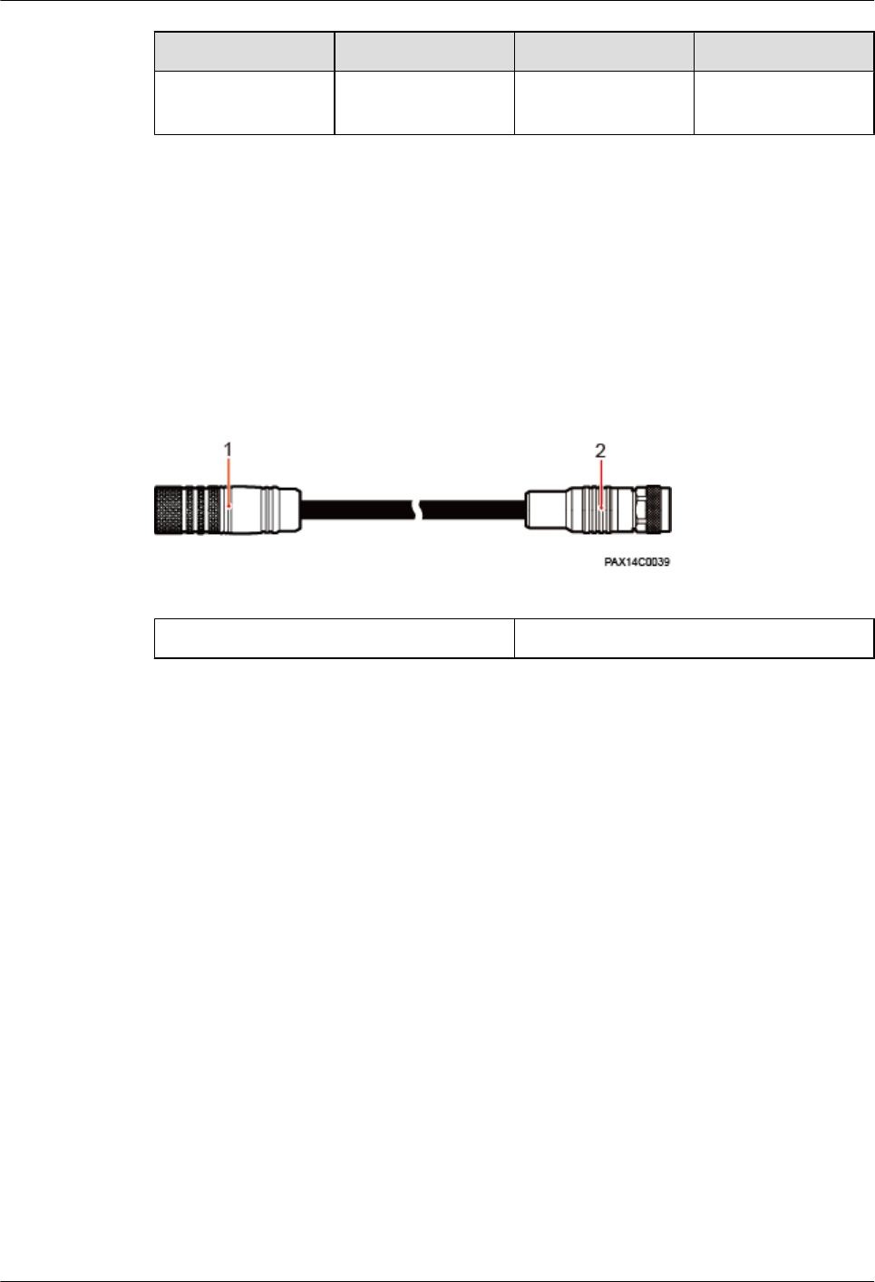
An RF jumper has a type N male connector at one end and a Smart-type N male connector at
the other end. Figure 4-8 shows the appearance of an RF jumper.
Figure 4-8 RF jumper appearance
(1) Smart-type N male connector (2) Type N male connector
BTS3911E
Hardware Description 4 BTS3911E Cables
Issue Draft A (2015-07-30) Huawei Proprietary and Confidential
Copyright © Huawei Technologies Co., Ltd.
17
5 (Optional) GPS Antenna
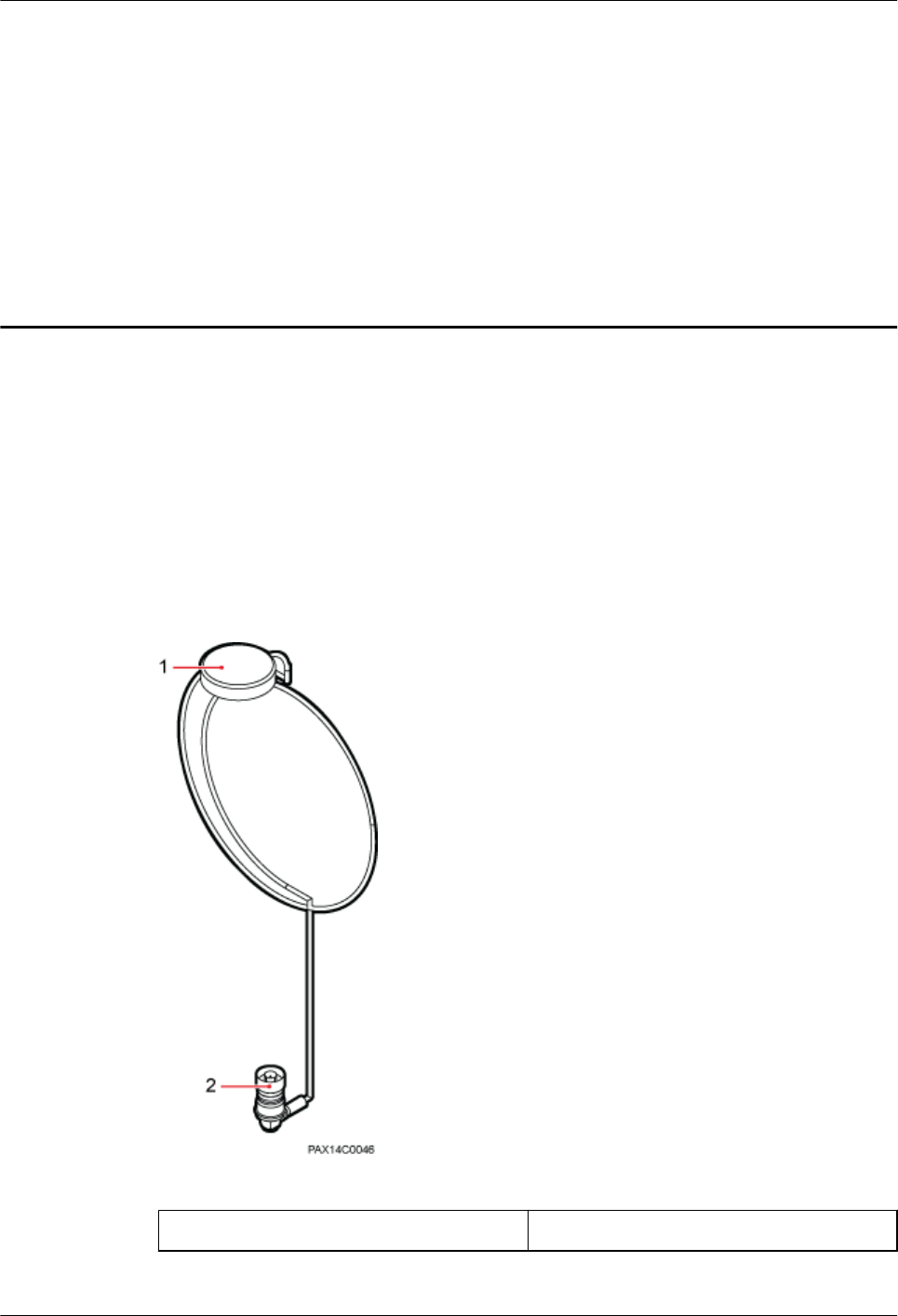
A GPS antenna connects to the BTS3911E for clock synchronization. The GPS antenna is
optional.
Appearance
A GPS antenna has a Smart-type N male connector at one end. Figure 5-1 shows the appearance
of a GPS antenna.
Figure 5-1 GPS antenna appearance
(1) GPS antenna (2) Smart-type N male connector
BTS3911E
Hardware Description 5 (Optional) GPS Antenna
Issue Draft A (2015-07-30) Huawei Proprietary and Confidential
Copyright © Huawei Technologies Co., Ltd.
18

BTS3911E
Hardware Description 5 (Optional) GPS Antenna
Issue Draft A (2015-07-30) Huawei Proprietary and Confidential
Copyright © Huawei Technologies Co., Ltd.
19

6 Typical Networking and Cable Connection
This section describes the BTS3911E networking modes and cable connection principles.
6.1 Typical Networking
6.2 Cable Connection Principles
BTS3911E
Hardware Description 6 Typical Networking and Cable Connection
Issue Draft A (2015-07-30) Huawei Proprietary and Confidential
Copyright © Huawei Technologies Co., Ltd.
20
6.1 Typical Networking
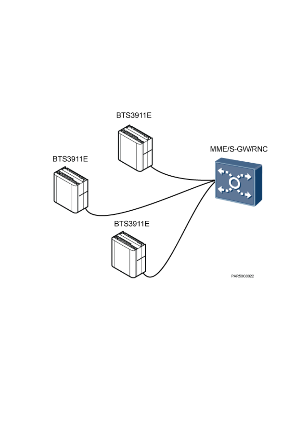
The BTS3911E supports the star and chain topologies.
Star Topology
The star topology is the most commonly used topology and applies to densely populated areas.
Figure 6-1
Figure 6-1 Star topology
Chain Topology
The chain topology applies to belt-shaped and sparsely populated areas, such as areas along
highways and railways. Figure 6-2
BTS3911E
Hardware Description 6 Typical Networking and Cable Connection
Issue Draft A (2015-07-30) Huawei Proprietary and Confidential
Copyright © Huawei Technologies Co., Ltd.
21
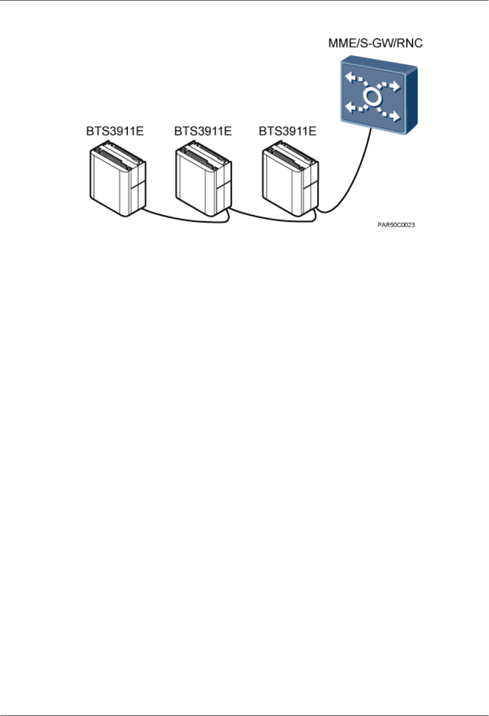
Figure 6-2 Chain topology
6.2 Cable Connection Principles
This section describes the connection principles for the PGND cable, power cable, transmission
cable, alarm cable, and RF jumper.
PGND Cable
The PGND cable length must not exceed 30 m.
Power Cable
The power cable length must not exceed 100 m.
Transmission Cable
lAn Ethernet cable or fiber optic cable can be used for transmission between a BTS3911E
and the MME/S-GW/RNC. A standard fiber optic cable is 70 m long or shorter. An Ethernet
cable must be made onsite, with a maximum length of 100 m.
lA maximum of three levels of BTS3911Es can be cascaded over Ethernet cables or
(recommended) fiber optic cables. The maximum distance between two BTS3911Es
cascaded over an Ethernet cable is 100 m.
Alarm Cable
The alarm cable length must not exceed 100 m.
RF Jumper
The RF jumper length depends on scenario-specific coverage requirements and must not exceed
10 m.
BTS3911E
Hardware Description 6 Typical Networking and Cable Connection
Issue Draft A (2015-07-30) Huawei Proprietary and Confidential
Copyright © Huawei Technologies Co., Ltd.
22
7 Power Requirements
This section describes the requirements on the upper-level (customer-provided) circuit breakers
and cross-sectional areas of power cables for the BTS3911Es.
Slow-blow fuses of the gL (DIN VDE)/gG (IEC) class in accordance with IEC60269-1 are
recommended. Fuses of the same specifications must be configured for L and N wires for the
sake of O&M security.
Type C bipolar circuit breakers in accordance with IEC60934 are recommended. Circuit breakers
must be configured for L and N wires for the sake of O&M security.
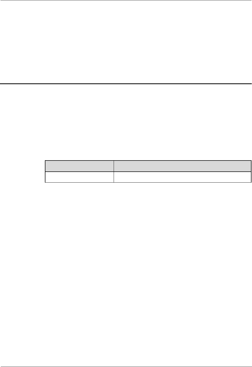
Table 7-1 describes the recommended specifications.
Table 7-1 Requirements on the upper-level circuit breakers and power cables
Power Supply Current of the Upper-
level AC Circuit Breakers
(or Fuses)
Cross-Sectional Area of
the Input Power Cable
220 V AC single-phase lMinimum value: 5 A
lRecommended value: 16
A
lMaximum value: 20 A
1.5 mm2 to 2.5 mm2
110 V AC dual-live-wire
110 V AC single-phase
NOTE
lThe requirements provided in the preceding table are based on the peak power of a BTS3911E and do
not represent power consumption when the BTS3911E is running.
lMinimum value: Ensures that a BTS3911E can work normally under normal circumstances. However,
lightning strikes or abnormal voltage fluctuations may trip the circuit breaker or melt the fuse.
lRecommended value: Ensures that a BTS3911E can work normally under normal circumstances and
that the circuit breaker does not trip in the event of lightning strikes or abnormal voltage fluctuations.
lMaximum value: Indicates the maximum rated current allowed in the product design.
BTS3911E
Hardware Description 7 Power Requirements
Issue Draft A (2015-07-30) Huawei Proprietary and Confidential
Copyright © Huawei Technologies Co., Ltd.
23
8 Engineering Specifications
BTS3911E engineering specifications include power supply specifications, equipment
specifications, environment specifications, surge protection specifications, and standards
compliance.
For more details, see BTS3911E Technical Description.
Power Supply Specifications
Table 8-1 describes the input and output power specifications of a BTS3911E.
Table 8-1 Power supply specifications
Item Specifications
Input power 100 V AC to 240 V AC
Output power (PoE) -37 V DC to -57 V DC
Equipment Specifications
Table 8-2 describes the dimensions and weight of a BTS3911E.
Table 8-2 Equipment specifications
Item Dimensions (W x H x D) Weight
BTS3911E with internal antennas 300 mm x 290 mm x 166 mm ≤ 13 kg
BTS3911E without internal
antennas
300 mm x 290 mm x 118 mm ≤ 11 kg
BTS3911E
Hardware Description 8 Engineering Specifications
Issue Draft A (2015-07-30) Huawei Proprietary and Confidential
Copyright © Huawei Technologies Co., Ltd.
24

Environment Specifications
Table 8-3 describes the environment specifications of a BTS3911E.
Table 8-3 Environment specifications
Item Specifications
Operating temperature -40oC to +50oC (with solar radiation)
-40oC to +45oC (without solar radiation)
Storage temperature -40oC to +70oC
Relative humidity 5% RH to 95% RH
Absolute humidity (1 to 30) g/m3
Altitude -60 m to +1800 m
Operating atmospheric pressure 70 kPa to 106 kPa
Operating environment European Telecommunication Standards
(ETS) 30 019-1-4 Class4.1
Storage environment ETSI EN300019-1-1 class1.2 "Weather
protected, not temperature-controlled storage
locations"
Transportation environment ETSI EN300019-1-2 class 2.3 "Public
transportation"
Protection rating IP65
Anti-seismic performance IEC 60068-2-57 Environmental testing – Part
2-57: Tests – Test Ff: Vibration – Time-
history method
ETSI EN300019-2-4
YD5083-99: Interim Provisions for Test of
Anti-seismic Performances of
Telecommunications Equipment
(telecommunications industry standard in
People's Republic of China)
Protection against the moisture, salt spray,
and fungus
IEC60068-2-30
IEC60068-2-52
IEC60068-2-10
Storage time To avoid product degradation, it is a good
practice to put the BTS3911E into use within
the first year of storage.
BTS3911E
Hardware Description 8 Engineering Specifications
Issue Draft A (2015-07-30) Huawei Proprietary and Confidential
Copyright © Huawei Technologies Co., Ltd.
25
Surge Protection Specifications
Table 8-4 describes the surge protection specifications of the PWR port on a BTS3911E.
Table 8-4 Surge protection specifications of the PWR port
Port Surge Protection Mode Specifications
PWR Differential mode 20 kA (8/20us)
Common mode 20 kA (8/20us)
Standards Compliance
Table 8-5 describes the standards with which the BTS3911E complies.
Table 8-5 Standards with which the BTS3911E complies
Item Specifications
EMC The BTS3911E complies with the following
standards related to electromagnetic
compatibility:
lCISPR 22
lEN 55022
lEN 301 489-17
lEN 301 489-23
lCISPR 24
lIEC 61000-4-2
lIEC 61000-4-3
lIEC 61000-4-4
lIEC 61000-4-5
lIEC 61000-4-6
lIEC 61000-4-29
lGB 9254
lETSI 301 489-1
lVCCI V-3
3GPP R99, R4, R5, R6, R7, R8, R9, and R10
Environmental standards RoHS
Surge protection standards IEC61000-4-5, IEC 61312-1, and YD 5098
Protection standards YD 5098, YD 5068-98, and IEC 61000-4-5
BTS3911E
Hardware Description 8 Engineering Specifications
Issue Draft A (2015-07-30) Huawei Proprietary and Confidential
Copyright © Huawei Technologies Co., Ltd.
26

Item Specifications
Safety standards UL60950-1, IEC60950-1, EN60950-1, AS/
NZS60950-1, UL60950-22, IEC60950-22,
EN60950-22, and AS/NZS60950-22
Environment standards IEC 68-2-1, IEC 68-2-2, IEC60068-2-2,
ETSI EN300019-1-1, ETSI EN300019-1-2,
ETSI EN300019-1-4, and ETSI
EN300019-2-4
BTS3911E
Hardware Description 8 Engineering Specifications
Issue Draft A (2015-07-30) Huawei Proprietary and Confidential
Copyright © Huawei Technologies Co., Ltd.
27

BTS3911E
V100R011C00
Installation Guide
Issue
Draft A
Date
2015-07-30
HUAWEI TECHNOLOGIES CO., LTD.

Issue Draft A (2015-07-30)
Huawei Proprietary and Confidential
Copyright © Huawei Technologies Co., Ltd
i
Copyright © Huawei Technologies Co., Ltd. 2015. All rights reserved.
No part of this document may be reproduced or transmitted in any form or by any means without prior
written consent of Huawei Technologies Co., Ltd.
Trademarks and Permissions
and other Huawei trademarks are trademarks of Huawei Technologies Co., Ltd.
All other trademarks and trade names mentioned in this document are the property of their respective
holders.
Notice
The purchased products, services and features are stipulated by the contract made between Huawei and
the customer. All or part of the products, services and features described in this document may not be
within the purchase scope or the usage scope. Unless otherwise specified in the contract, all statements,
information, and recommendations in this document are provided "AS IS" without warranties, guarantees
or representations of any kind, either express or implied.
The information in this document is subject to change without notice. Every effort has been made in the
preparation of this document to ensure accuracy of the contents, but all statements, information, and
recommendations in this document do not constitute a warranty of any kind, express or implied.
Huawei Technologies Co., Ltd.
Address:
Huawei Industrial Base
Bantian, Longgang
Shenzhen 518129
People's Republic of China
Website:
http://www.huawei.com
Email:
support@huawei.com

BTS3911E
Installation Guide
Contents
Issue Draft A (2015-07-30)
Huawei Proprietary and Confidential
Copyright © Huawei Technologies Co., Ltd
ii
Contents
1 BTS3911E Installation Guide ...................................................................................................... 1
1.1 Changes in BTS3911E Installation Guide .................................................................................................................... 2
1.2 Installation Preparations ............................................................................................................................................... 2
1.2.1 Installation Environment ............................................................................................................................................ 2
1.2.2 Reference Documents ................................................................................................................................................ 3
1.2.3 Tools and Instruments ................................................................................................................................................ 3
1.2.4 Skills and Requirements for Installation Personnel ................................................................................................... 5
1.2.5 Installation Scenarios ................................................................................................................................................. 5
1.2.6 Installation Clearance Requirements ......................................................................................................................... 7
1.3 Unpacking Inspection ................................................................................................................................................... 8
1.4 Obtaining the SN ........................................................................................................................................................ 10
1.5 Installation Process ..................................................................................................................................................... 11
1.6 (Optional) Installing a TF Card ................................................................................................................................... 12
1.7 Installing a BTS3911E ................................................................................................................................................ 14
1.7.1 Mounting Kits .......................................................................................................................................................... 14
1.7.2 Installing a BTS3911E on a Pole ............................................................................................................................. 15
1.7.3 Installing a BTS3911E on a Wall ............................................................................................................................. 17
1.8 Installing Cables ......................................................................................................................................................... 20
1.8.1 Cabling Requirements.............................................................................................................................................. 20
1.8.2 Cable Connections ................................................................................................................................................... 22
1.8.3 Installing a PGND Cable ......................................................................................................................................... 23
1.8.4 (Optional) Installing an RF Jumper ......................................................................................................................... 25
1.8.5 Opening the Maintenance Cavity Covers ................................................................................................................ 26
1.8.6 Installing a Power Cable .......................................................................................................................................... 28
1.8.7 Installing an Alarm Cable ........................................................................................................................................ 30
1.8.8 Installing Transmission Cables ................................................................................................................................ 31
1.8.8.1 Installing an FE/GE Fiber Optic Cable ................................................................................................................. 31
1.8.8.2 Installing an FE/GE Ethernet Cable...................................................................................................................... 33
1.8.8.3 (Optional) Installing an FE/GE Fiber Optic Cable for Cascading ........................................................................ 34
1.8.8.4 (Optional) Installing an FE/GE Ethernet Cable for Cascading ............................................................................. 36
1.8.9 Closing the Maintenance Cavity Covers .................................................................................................................. 37
1.8.10 Adjusting Installation Angles ................................................................................................................................. 39
1.9 Checking the Hardware Installation............................................................................................................................ 40

BTS3911E
Installation Guide
Contents
Issue Draft A (2015-07-30)
Huawei Proprietary and Confidential
Copyright © Huawei Technologies Co., Ltd
iii
1.10 Performing a Power-On Check ................................................................................................................................. 41
1.11 References ................................................................................................................................................................. 42
1.11.1 SN Collection Template ......................................................................................................................................... 42
1.11.2 Assembling a Tool-less Female Connector (Pressfit Type) and a Power Cable ..................................................... 43
1.11.3 Assembling a Shielded RJ45 Connector and an Ethernet Cable ............................................................................ 46
BTS3911E
Installation Guide
1 BTS3911E Installation Guide
Issue Draft A (2015-07-30)
Huawei Proprietary and Confidential
Copyright © Huawei Technologies Co., Ltd
1
1 BTS3911E Installation Guide
Introduction
This document describes how to install a BTS3911E in different scenarios and provides the
hardware installation checklist as a reference.
Product Version
The following table lists the product version to which this document applies.
Product Name
Product Version
BTS3911E
V100R011C00
Intended Audience
This document is intended for:
BTS3911E installation engineers
System engineers
Site maintenance engineers
Organization
1.1 Changes in BTS3911E Installation Guide
This section describes the changes in BTS3911E Hardware Description.
1.2 Installation Preparations
This section describes the preparations for installation. Before starting the installation, you
must get the installation environment ready, obtain the required reference documents, tools,
and instruments, and familiarize yourself with the skills required.
1.3 Unpacking Inspection
This section describes how to unpack and check the delivered materials to ensure that all the
materials are included and intact.
1.4 Obtaining the SN

BTS3911E
Installation Guide
1 BTS3911E Installation Guide
Issue Draft A (2015-07-30)
Huawei Proprietary and Confidential
Copyright © Huawei Technologies Co., Ltd
2
This section describes how to obtain the serial number (SN) of a BTS3911E. Before installing
the BTS3911E, record its SN for future use during commissioning.
1.5 Installation Process
This section describes the process for installing a BTS3911E. The process includes:
Installing a BTS3911E
Installing cables
Checking the hardware installation
Performing a power-on check
1.7 Installing a BTS3911E
This section describes the procedure and precautions for installing a BTS3911E.
1.8 Installing Cables
This section describes the procedure and precautions for installing cables.
1.9 Checking the Hardware Installation
This section describes how to check the hardware installation after a BTS3911E is installed.
1.10 Performing a Power-On Check
This section describes the procedure for performing a power-on check on a BTS3911E.
1.11 References
This section describes reference information and common operations involved during
installation.
1.1 Changes in BTS3911E Installation Guide
This section describes the changes in BTS3911E Hardware Description.
Draft A (2015-07-30)
This is a draft.
1.2 Installation Preparations
This section describes the preparations for installation. Before starting the installation, you
must get the installation environment ready, obtain the required reference documents, tools,
and instruments, and familiarize yourself with the skills required.
1.2.1 Installation Environment
Before starting the installation, ensure that the power supply equipment, transmission
equipment, and related matching equipment are ready.
BTS3911E
Installation Guide
1 BTS3911E Installation Guide
Issue Draft A (2015-07-30)
Huawei Proprietary and Confidential
Copyright © Huawei Technologies Co., Ltd
3
Precautions for Site Selection
Do not install a BTS3911E near an interference source, such as a broadcast and
television tower, high and low-voltage substation, high-voltage tower, high-power radio
transmitter, and radar station.
For the sake of surge protection, the mounting height of a BTS3911E should not be
greater than 10 m. Do not install a BTS3911E along a highway or railway or on the
mountain top, tower, standalone pole in a suburban area or open field, or standalone
rooftop in a non-urban area.
Requirements for the Upper-level Circuit Breaker
Type C upper-level AC circuit breakers or slow-blow fuses must be used for power cables.
The maximum current must not exceed 16 A. Table 1-1 describes the recommended
specifications.
Table 1-1 Requirements for the upper-level circuit breaker
Input Voltage Type
Current of the Upper-level AC Circuit
Breakers (or Fuses)
220 V AC single-phase or 110 V AC dual-
live-wire
3 A to 4 A
110 V AC single-phase
5 A to 6 A
Requirements for Surge Protection and Grounding
Huawei by default uses a three-core power cable to connect a BTS3911E and external power
supply equipment. The power supply side must ensure that the PE wire of the three-core
power cable can be properly grounded. In outdoor installation scenarios or outdoor cabling
scenarios, PGND cables must be used to guarantee the surge protection and grounding for the
ground terminals of the mounting kits.
1.2.2 Reference Documents
This section describes reference documents required for installation.
Before starting the installation, you must be familiar with the following reference
documents:
− Safety Information
− BTS3911E Hardware Description
During the installation, you must be familiar with Installation Reference.
1.2.3 Tools and Instruments
Before starting the installation, prepare the following tools and instruments.
Marker (diameter ≤ 10 mm)
Hammer drill (Ø8, Ø12,
Ø14, or Ø16 bore)
Rubber mallet
BTS3911E
Installation Guide
1 BTS3911E Installation Guide
Issue Draft A (2015-07-30)
Huawei Proprietary and Confidential
Copyright © Huawei Technologies Co., Ltd
4
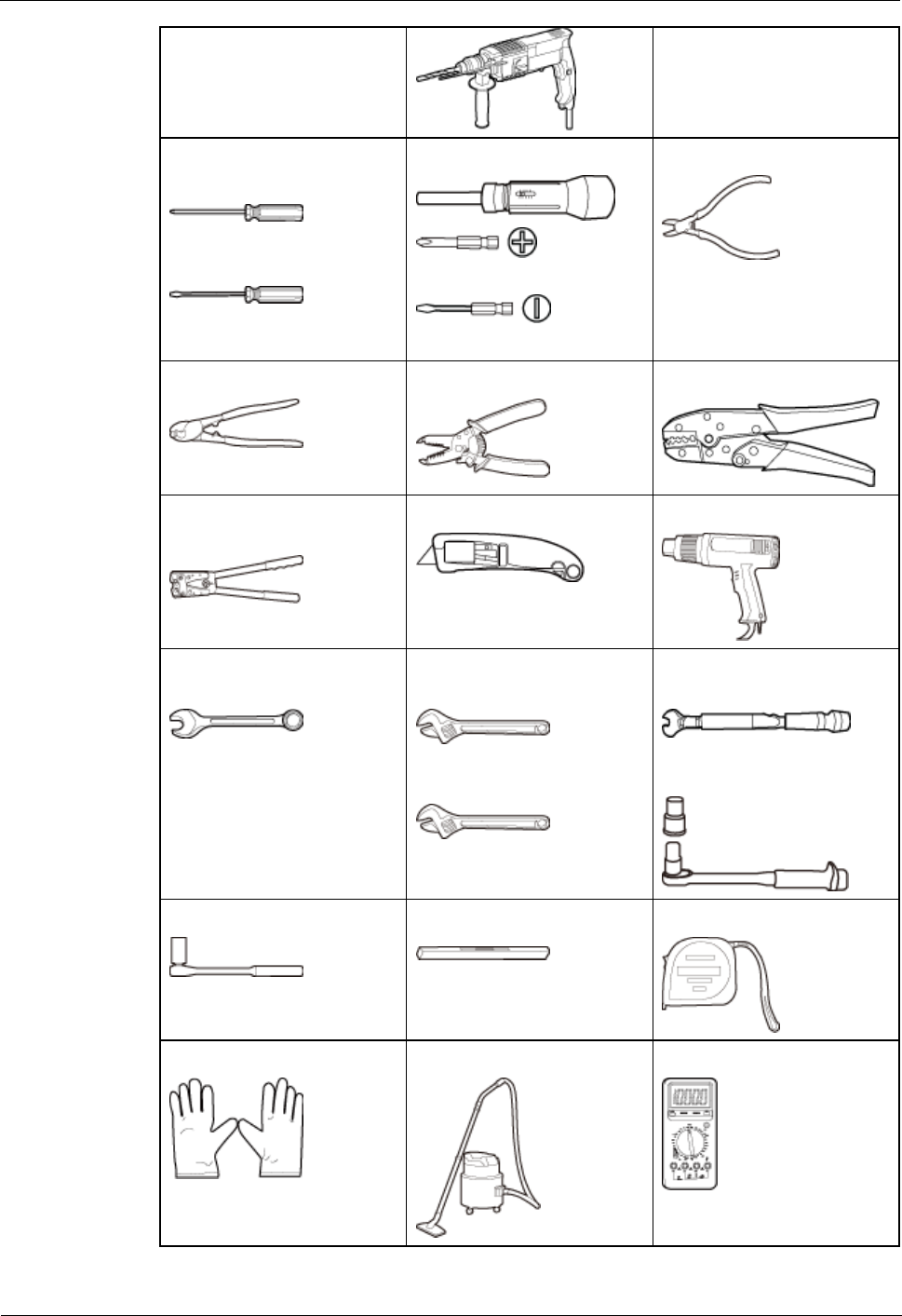
Phillips screwdriver (M3 to
M6, length ≤ 200 m)
Flat-head screwdriver (M3
to M6)
Torque screwdriver
Phillips (M3 to M8)
Flat-head (M3 to M8)
Diagonal pliers
Cable cutter
Wire stripper
COAX crimping tool
Crimping tool for power
cables
Utility knife
Heat gun
Combination wrench (bore:
17 mm, 19 mm, or 21 mm)
Adjustable wrench (bore ≥
32 mm)
Adjustable wrench (bore ≤
19 mm)
Torque wrench (bore: 17
mm, 19 mm, or 21 mm)
Torque wrench (30 N·m to
50 N·m)
Socket wrench (M10, M12)
Level
Measuring tape
ESD gloves
ESD wrist strap
Vacuum cleaner
Multimeter

BTS3911E
Installation Guide
1 BTS3911E Installation Guide
Issue Draft A (2015-07-30)
Huawei Proprietary and Confidential
Copyright © Huawei Technologies Co., Ltd
5
RJ11 crimping tool
-
-
1.2.4 Skills and Requirements for Installation Personnel
Installation personnel must be qualified, trained, and familiar with correct operation methods
and safety precautions before performing any operations.
Before starting the installation, pay attention to the following items:
The customer's technical engineers must be trained by Huawei and be familiar with the
proper installation and engineering methods.
The number of required installation personnel depends on the engineering schedule and
installation environment. Generally, three to five installation personnel are necessary.
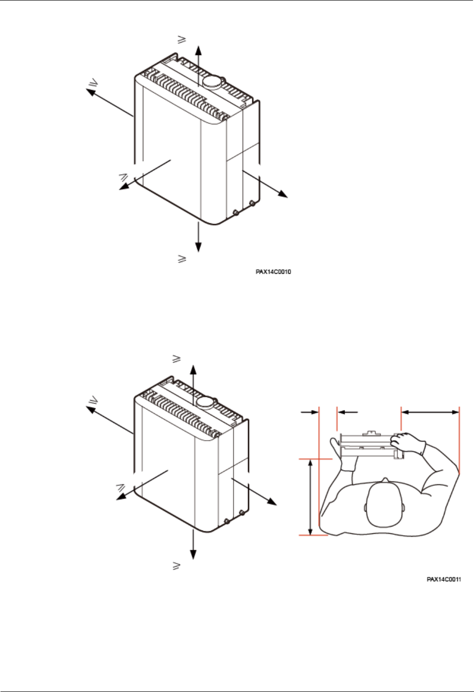
1.2.5 Installation Scenarios
A BTS3911E can be installed on a pole or a wall.
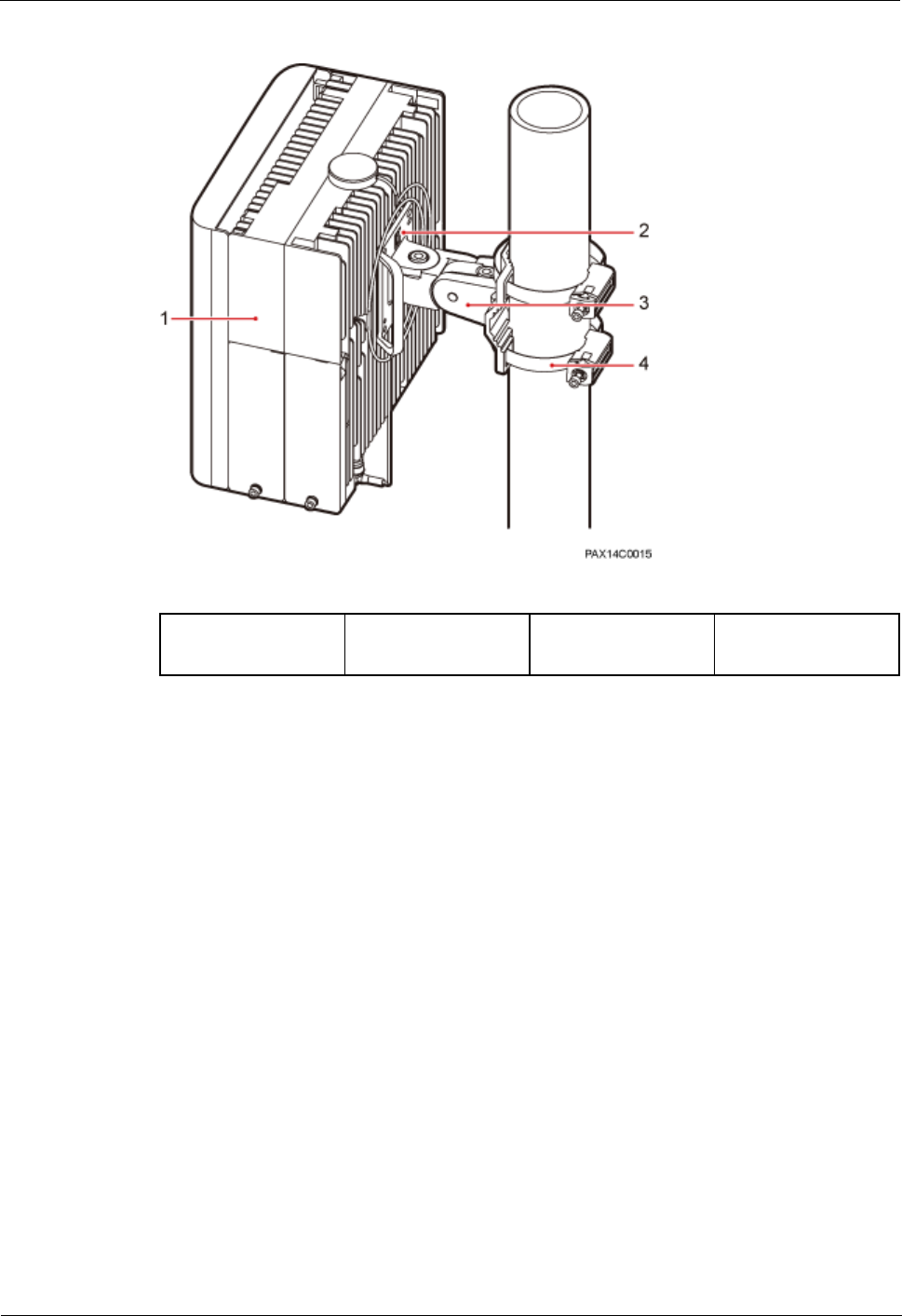
Pole-mounted Installation
A BTS3911E can be installed on a pole with a diameter of 60 mm to 381 mm.
Figure 1-1 illustrates a pole-mounted BTS3911E.
BTS3911E
Installation Guide
1 BTS3911E Installation Guide
Issue Draft A (2015-07-30)
Huawei Proprietary and Confidential
Copyright © Huawei Technologies Co., Ltd
6
Figure 1-1 Pole-mounted installation
(1) BTS3911E
(2) Angle adjusting
attachment plate
(3) Angle adjusting
mounting bracket
(4) Steel belt
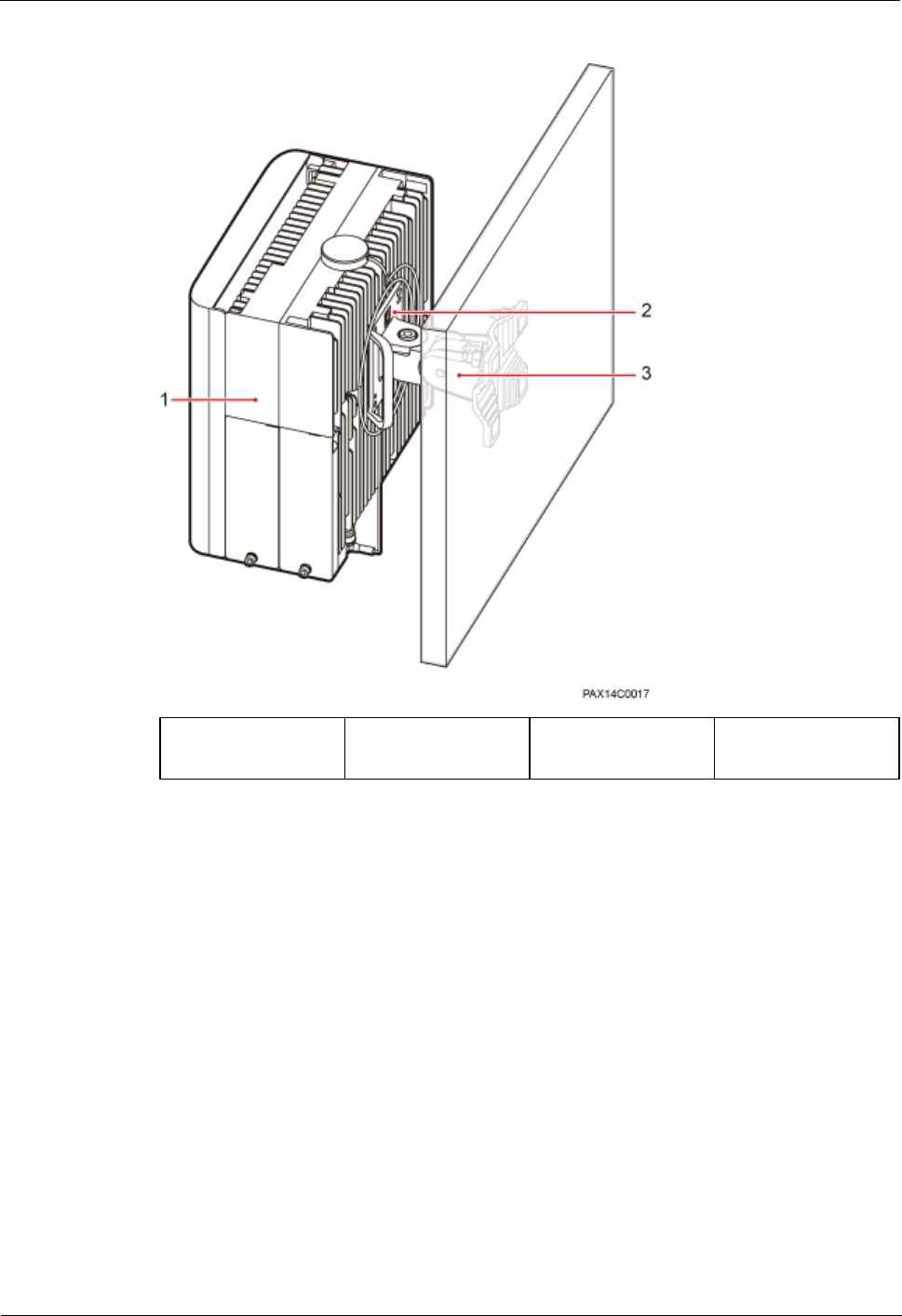
Wall-mounted Installation
In wall-mounted installation scenarios, note the following:
The wall on which a single BTS3911E is to be installed can carry a weight of 60 kg
without damage.
Expansion bolts must be torqued to 28 N·m to ensure the bolts work properly without
causing cracks on the wall.
Figure 1-2 illustrates a wall-mounted BTS3911E.
BTS3911E
Installation Guide
1 BTS3911E Installation Guide
Issue Draft A (2015-07-30)
Huawei Proprietary and Confidential
Copyright © Huawei Technologies Co., Ltd
7
Figure 1-2 Wall-mounted installation
(1) BTS3911E
(2) Angle adjusting
attachment plate
(3) Angle adjusting
mounting bracket
-
1.2.6 Installation Clearance Requirements
This section describes the clearance requirements for installing a BTS3911E on a pole or wall
Figure 1-3 shows the recommended installation clearances around a BTS3911E.
BTS3911E
Installation Guide
1 BTS3911E Installation Guide
Issue Draft A (2015-07-30)
Huawei Proprietary and Confidential
Copyright © Huawei Technologies Co., Ltd
8
Figure 1-3 Recommended installation clearances around a BTS3911E
500 mm
400 mm
800 mm
≥ 600 mm
600 mm
Figure 1-4 shows the minimum installation clearances around a BTS3911E.
Figure 1-4 Minimum installation clearances around a BTS3911E
500 mm
300 mm
600 mm
≥400 mm
400 mm
400 mm
300 mm
600 mm
1.3 Unpacking Inspection
This section describes how to unpack and check the delivered materials to ensure that all the
materials are included and intact.
BTS3911E
Installation Guide
1 BTS3911E Installation Guide
Issue Draft A (2015-07-30)
Huawei Proprietary and Confidential
Copyright © Huawei Technologies Co., Ltd
9
Prerequisites
CAUTION
After a BTS3911E is unpacked, power it on within 24 hours. If the BTS3911E is powered off
for maintenance, restore power to it within 24 hours.
Context
When transporting, moving, or installing the equipment, components, or parts, you must:
Prevent them from colliding with doors, walls, shelves, or other objects.
Wear clean gloves, and avoid touching the equipment, components, or parts with bare hands, sweat-
soaked gloves, or dirty gloves.
Procedure
Step 1 Check the total number of articles in each packing case against the packing list.
If...
Then...
The total number tallies with the packing
list
Go to Step 2.
The total number does not tally with the
packing list
Find out the cause and contact the local
Huawei office.
Step 2 Check the exterior of each packing case.
If...
Then...
The outer packing is intact
Go to Step 3.
The packing case is severely damaged or
soaked
Find out the cause and contact the local
Huawei office.
Step 3 Check the type and quantity of the equipment in each packing case against the packing list.
If...
Then...
The type and quantity tallies with the
packing list
Sign the Packing List with the customer.
There is any shipment shortage or wrong
shipment
Fill in and submit the Cargo Shortage and
Mishandling Report.
There is damaged shipment
Fill in and submit the Article Replacement
Report.
BTS3911E
Installation Guide
1 BTS3911E Installation Guide
Issue Draft A (2015-07-30)
Huawei Proprietary and Confidential
Copyright © Huawei Technologies Co., Ltd
10
CAUTION
To protect the equipment from damage, keep the unpacked equipment and packing materials
indoors. To help find out the cause of any damage in the future, take photos of the storeroom,
rusted or eroded equipment, packing cases, and packing materials, and then file the photos.
----End
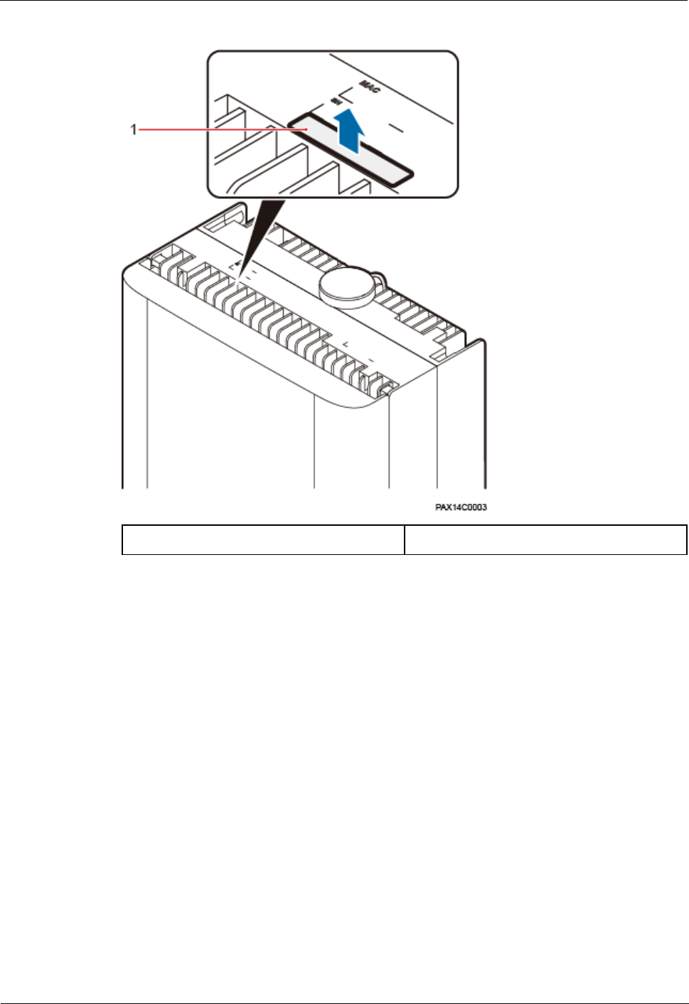
1.4 Obtaining the SN
This section describes how to obtain the serial number (SN) of a BTS3911E. Before installing
the BTS3911E, record its SN for future use during commissioning.
Context
The SN uniquely identifies a device and is required during commissioning. The SN label of a
BTS3911E is attached to the surface of the BTS3911E.
Procedure
Step 1 Remove the backup SN label from the surface of the BTS3911E. See Figure 1-5.
Before removing the backup SN label, photograph it.
BTS3911E
Installation Guide
1 BTS3911E Installation Guide
Issue Draft A (2015-07-30)
Huawei Proprietary and Confidential
Copyright © Huawei Technologies Co., Ltd
11
Figure 1-5 Removing the SN label
(1) Backup SN label
-
Step 2 Record the SN by using the template described in section 1.11.1 SN Collection Template, and
report it to the BTS3911E commissioning personnel.
----End
1.5 Installation Process
This section describes the process for installing a BTS3911E. The process includes:
Installing a BTS3911E
Installing cables
Checking the hardware installation
Performing a power-on check
Figure 1-6 outlines the process for installing a BTS3911E.
BTS3911E
Installation Guide
1 BTS3911E Installation Guide
Issue Draft A (2015-07-30)
Huawei Proprietary and Confidential
Copyright © Huawei Technologies Co., Ltd
12
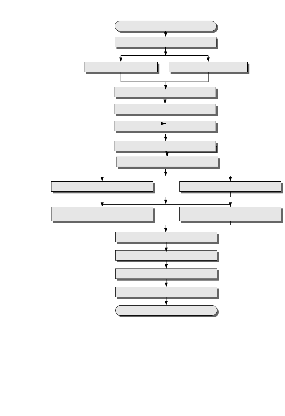
Figure 1-6 Process for installing a BTS3911E
IPP02C0007
Start
(Optional) Install a TF card
Install a PGND cable
Install a power cable
Install an FE/GE Ethernet cable Install an FE/GE fiber optic cable
(Optional) Install an alarm cable
Adjust installation angles
Check the hardware installation
Perform a power-on check
End
Open the maintenance cavity covers
(Optional) Install an FE/GE Ethernet
cable for cascading Install an FE/GE fiber optic cable for
cascading
Close the maintenance cavity covers
Install a BTS3911E on a pole Install a BTS3911E on a wall
(Optional) Install an RF jumper
1.6 (Optional) Installing a TF Card
This section describes the procedure and precautions for installing a TF card. This operation is
required if the TF card is to be used for BTS3911E deployment.
BTS3911E
Installation Guide
1 BTS3911E Installation Guide
Issue Draft A (2015-07-30)
Huawei Proprietary and Confidential
Copyright © Huawei Technologies Co., Ltd
13
Prerequisites
The TF card to be installed must be preconfigured with software and (or) configuration data.
For details, see BTS3911E Commissioning Guide.
Procedure
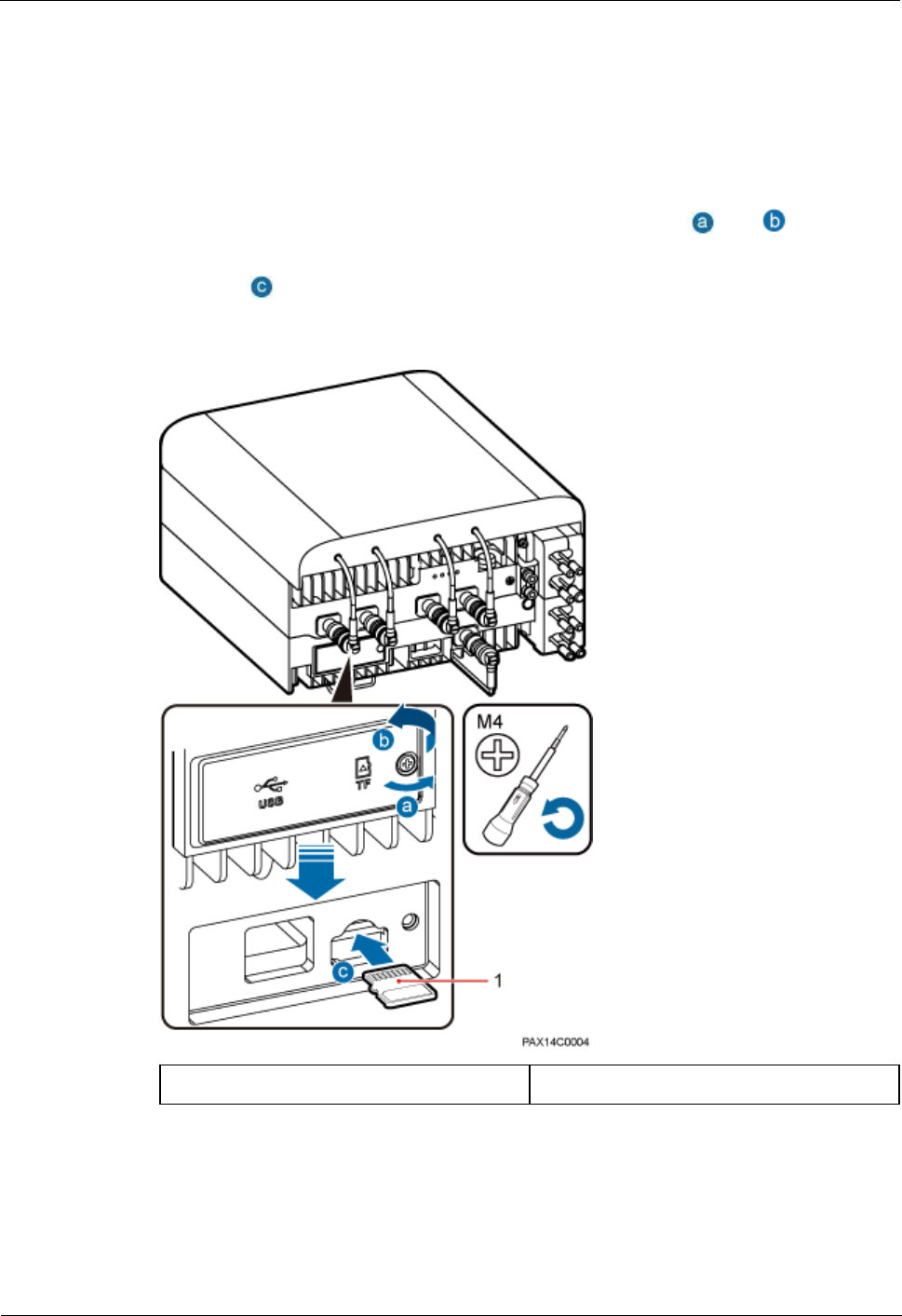
Step 1 Use a Phillips screwdriver to loosen the captive screw on the maintenance cavity cover on the
bottom of the BTS3911E. Open the maintenance cavity cover. See and in Figure 1-7.
Step 2 Insert the TF card into the anchor slot, as indicated by the direction on the maintenance cavity
cover. See in Figure 1-7.
Figure 1-7 Installing a TF card
(1) TF card
-
Step 3 Close the maintenance cavity cover, and use the Phillips screwdriver to torque the screw to
1.4 N·m.
----End
BTS3911E
Installation Guide
1 BTS3911E Installation Guide
Issue Draft A (2015-07-30)
Huawei Proprietary and Confidential
Copyright © Huawei Technologies Co., Ltd
14
1.7 Installing a BTS3911E
This section describes the procedure and precautions for installing a BTS3911E.
1.7.1 Mounting Kits
This section describes the kits for mounting a BTS3911E on a pole or wall.
Angle Adjusting Attachment Plate
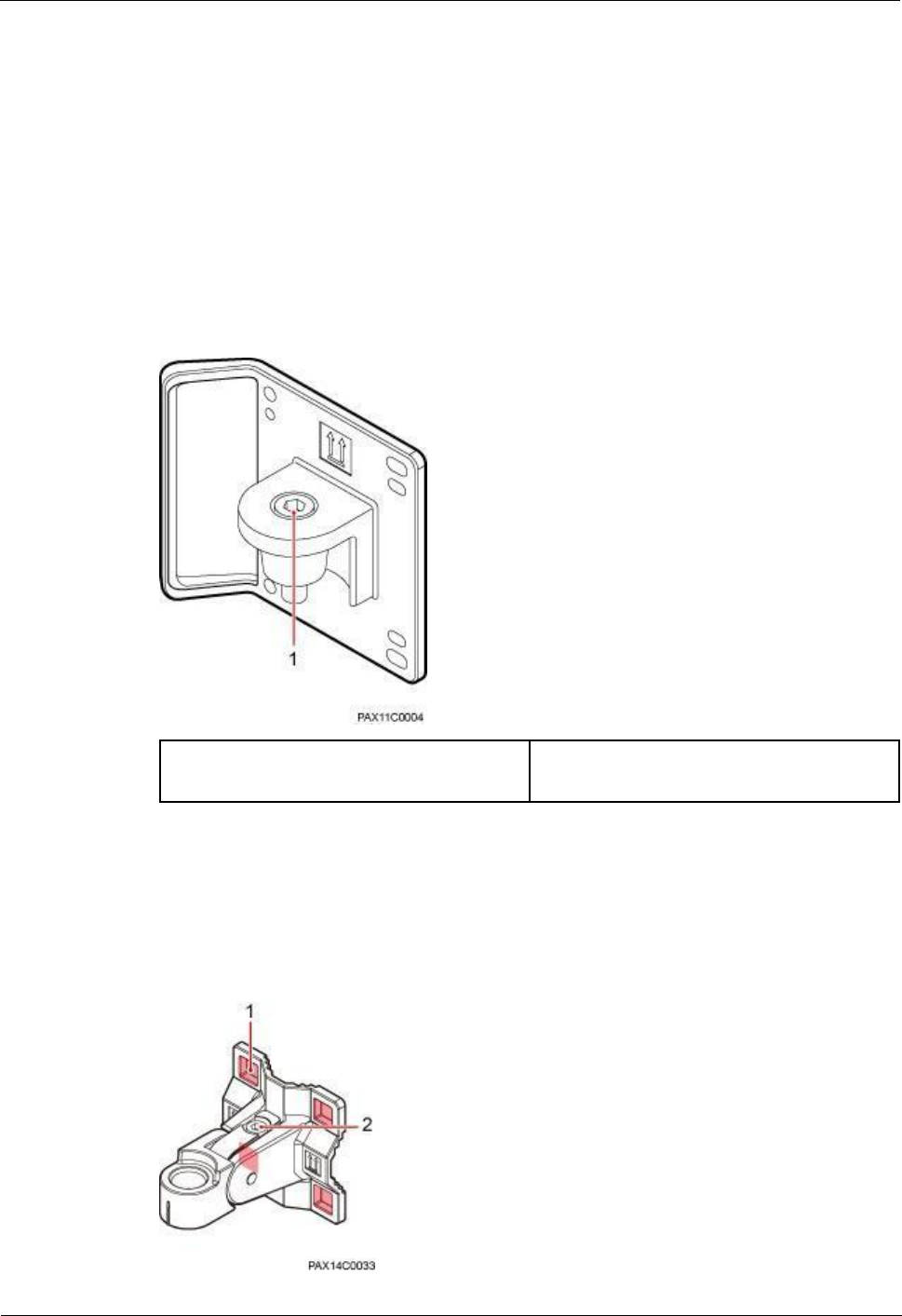
Figure 1-8 shows the appearance of an angle adjusting attachment plate.
Figure 1-8 Angle adjusting attachment plate
(1) Hole for a horizontal angle adjusting
screw
-
Angle Adjusting Mounting Bracket
Figure 1-9 shows the appearance of an angle adjusting mounting bracket.
Figure 1-9 Angle adjusting mounting bracket
BTS3911E
Installation Guide
1 BTS3911E Installation Guide
Issue Draft A (2015-07-30)
Huawei Proprietary and Confidential
Copyright © Huawei Technologies Co., Ltd
15
(1) Mounting hole for a steel belt or an
expansion bolt
(2) Hole for a vertical angle adjusting screw
1.7.2 Installing a BTS3911E on a Pole
This section describes the procedure and precautions for installing a BTS3911E on a pole.
Procedure
Step 1 Route two steel belts separately through the up and down mounting holes on the angle
adjusting mounting bracket, but do not route the steel belts through the buckles. See Figure 1-
10.
Figure 1-10 Routing steel belts
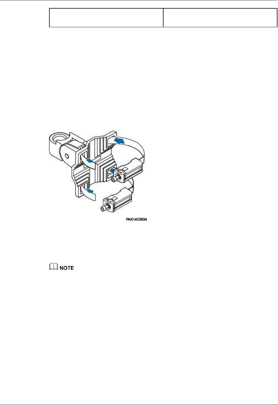
Step 2 Fit the angle adjusting mounting bracket onto the target pole as follows: Open the mounting
base according to the arrow direction, route the steel belts through the base, tighten the steel
belts, and use an M6 hex key screwdriver to torque the screws to 7 N·m. See Figure 1-11.
Redundant steel belts must be bound.
BTS3911E
Installation Guide
1 BTS3911E Installation Guide
Issue Draft A (2015-07-30)
Huawei Proprietary and Confidential
Copyright © Huawei Technologies Co., Ltd
16
Figure 1-11 Tightening steel belts
(1) Mounting base of steel belts
-
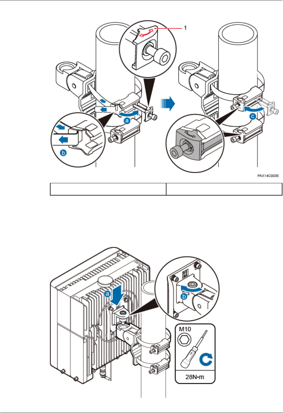
Step 3 Fit the BTS3911E onto the angle adjusting mounting bracket, and use an M10 hex key
screwdriver to torque the angle adjusting screw to 28 N·m. See Figure 1-12.
Figure 1-12 Fitting a BTS3911E onto an angle adjusting mounting bracket
BTS3911E
Installation Guide
1 BTS3911E Installation Guide
Issue Draft A (2015-07-30)
Huawei Proprietary and Confidential
Copyright © Huawei Technologies Co., Ltd
17
----End
1.7.3 Installing a BTS3911E on a Wall
This section describes the procedure and precautions for installing a BTS3911E on a wall.
Procedure
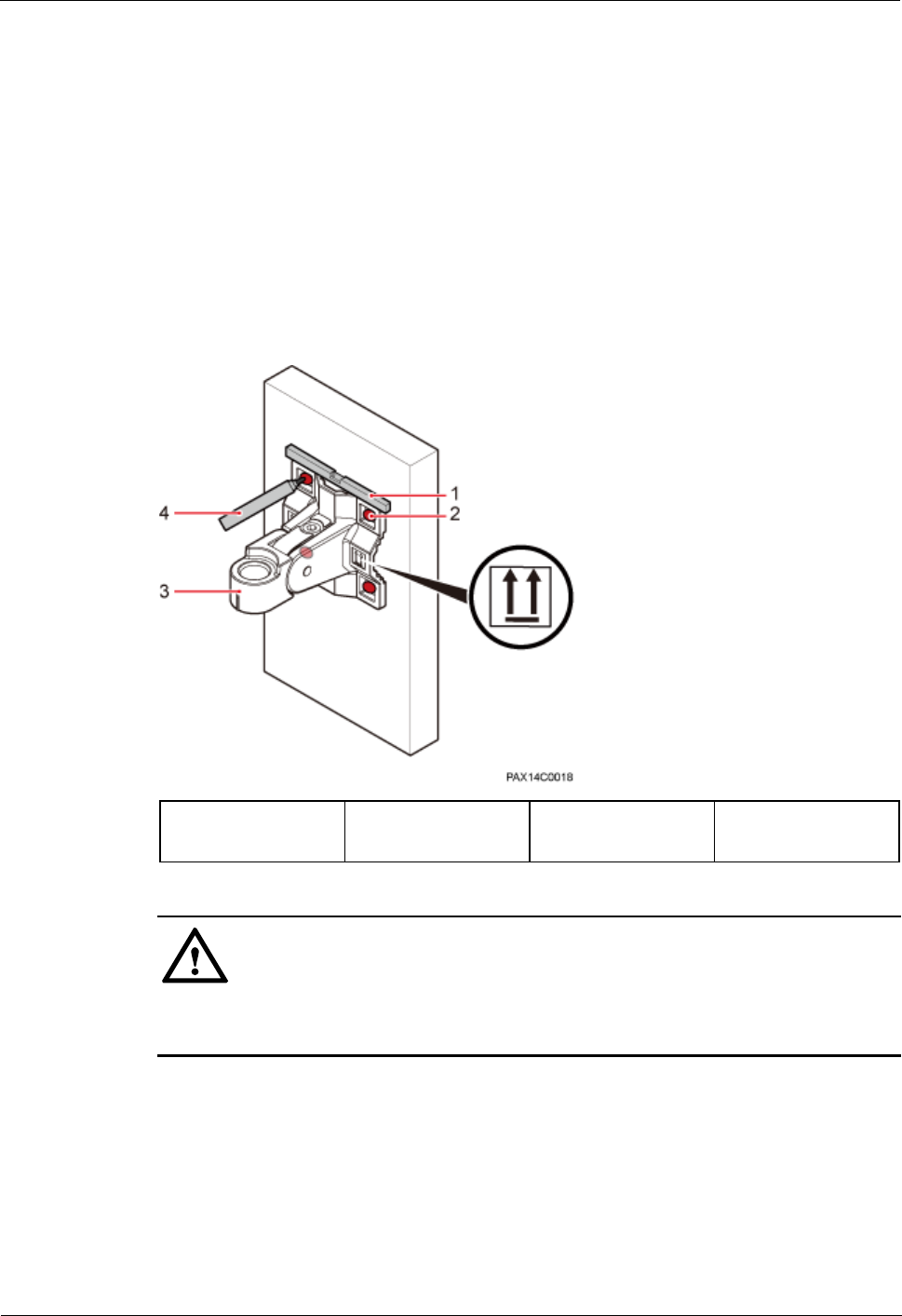
Step 1 Place the angle adjusting mounting bracket against the wall, use a level to verify that the
mounting bracket is placed horizontally, and use a marker to mark anchor points. See Figure
1-13.
Figure 1-13 Marking anchor points
(1) Level
(2) Mounting holes
(3) Angle adjusting
mounting bracket
(4) Marker
CAUTION
To prevent inhalation or eye contact with dust, take adequate preventive measures when
drilling holes.
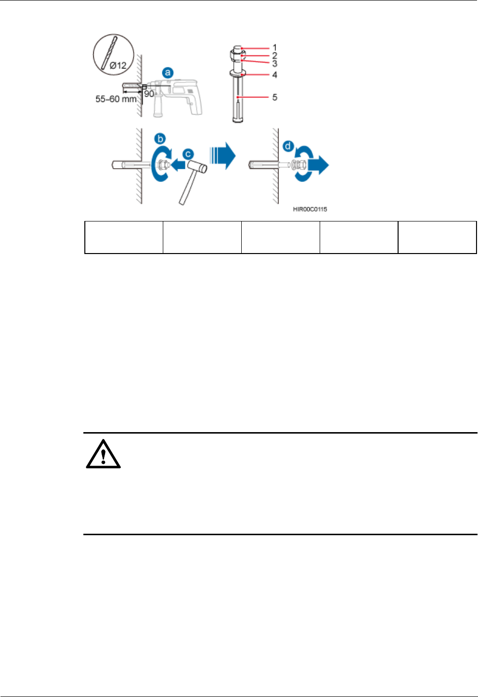
Step 2 Drill holes at the anchor points, and install expansion bolts. See Figure 1-14.
BTS3911E
Installation Guide
1 BTS3911E Installation Guide
Issue Draft A (2015-07-30)
Huawei Proprietary and Confidential
Copyright © Huawei Technologies Co., Ltd
18
Figure 1-14 Drilling holes and installing expansion bolts
(1) M10x80
expansion bolt
(2) Nut
(3) Spring
washer
(4) Flat washer
(5) Expansion
sleeve
Use a hammer drill with Ф12 bore to drill holes vertically at the marked anchor points.
Ensure that the holes have the same depth ranging from 55 mm to 60 mm.
Use a vacuum cleaner to clear the dust from inside and around the holes, and measure
the inter-hole spacing. If the spacing is too wide or too narrow, relocate positions and
drill holes again.
Partially tighten an expansion bolt and vertically insert it into each hole.
Use a rubber mallet to hit the expansion bolts until the entire expansion sleeve is in each
hole.
Remove the M10×80 bolt, nut, spring washer, and flat washer in sequence.
CAUTION
Level the front of each expansion sleeve with the wall after disassembling an expansion
bolt. Otherwise, the mounting bracket will not be securely installed on the wall.
Do not hammer the swell fixtures entirely into the wall. Instead, leave 8 mm to 12 mm of
each swell fixture outside the wall.
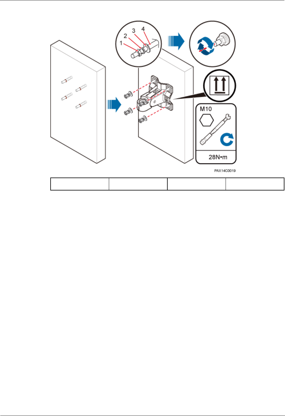
Step 3 Fit the angle adjusting mounting bracket onto the wall through the four expansion bolts, and
use an M10 socket wrench to torque the four expansion bolts to 28 N·m. See Figure 1-15.
BTS3911E
Installation Guide
1 BTS3911E Installation Guide
Issue Draft A (2015-07-30)
Huawei Proprietary and Confidential
Copyright © Huawei Technologies Co., Ltd
19
Figure 1-15 Fitting an angle adjusting mounting bracket onto the wall
(1) Nut
(2) Spring washer
(3) Flat washer
(4) Swell fixture
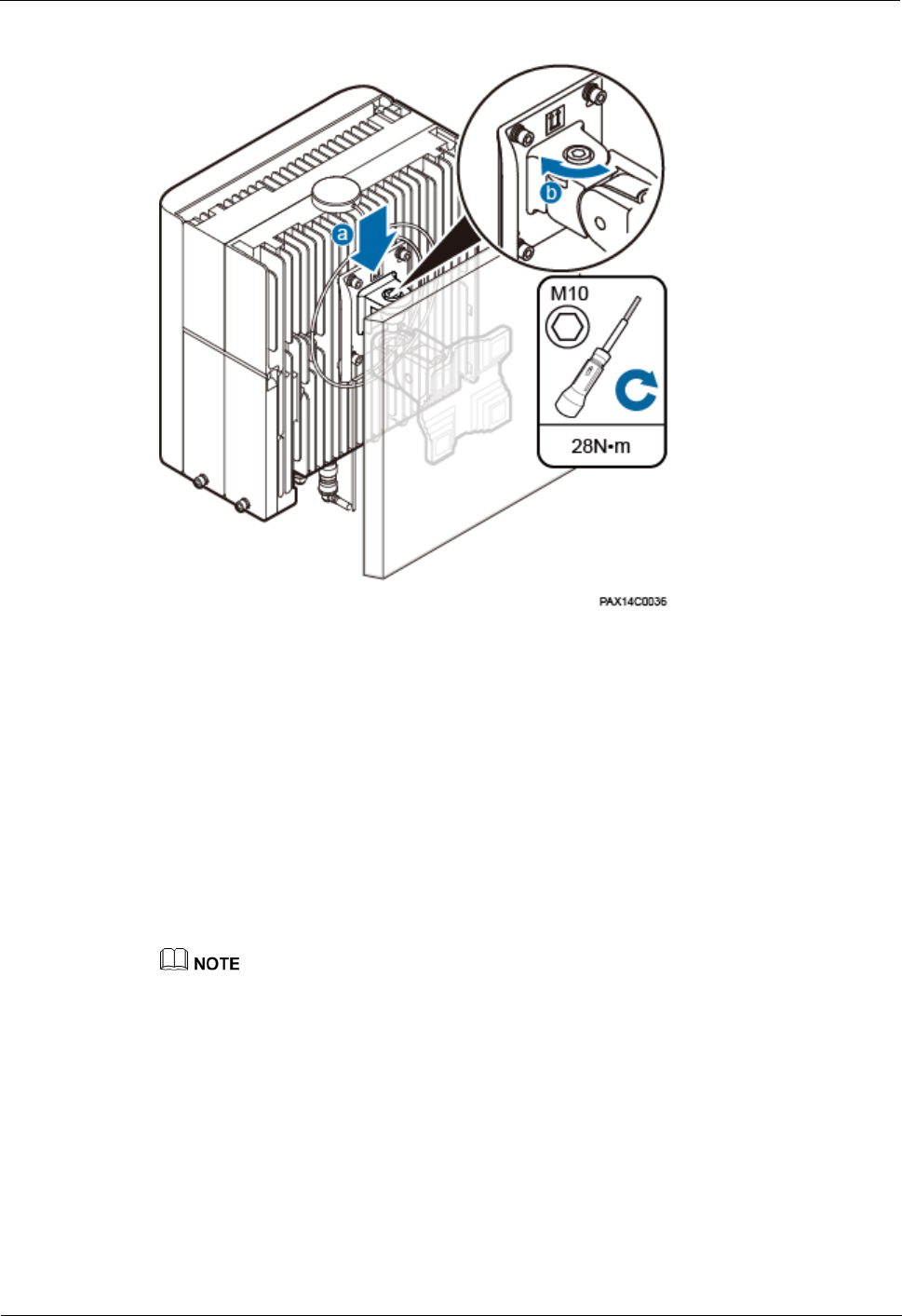
Step 4 Fit the BTS3911E onto the angle adjusting mounting bracket, and use an M10 hex key
screwdriver to torque the angle adjusting screw to 28 N·m. See Figure 1-16.
BTS3911E
Installation Guide
1 BTS3911E Installation Guide
Issue Draft A (2015-07-30)
Huawei Proprietary and Confidential
Copyright © Huawei Technologies Co., Ltd
20
Figure 1-16 Fitting a BTS3911E onto the angle adjusting mounting bracket
----End
1.8 Installing Cables
This section describes the procedure and precautions for installing cables.
1.8.1 Cabling Requirements
Cables must be routed according to the specified cabling requirements to prevent interference
between signals.
If a cable listed below is not required, skip the cabling requirements of the cable.
General Cabling Requirements
The bending radius of the cables must meet the following specifications:
The bending radius of a 7/8'' feeder must be greater than 250 mm, and the bending radius
of a 5/4'' feeder must be greater than 380 mm.
The bending radius of a 1/4'' jumper must be greater than 35 mm. The bending radius of
a super-flexible 1/2'' jumper must be greater than 50 mm, and the bending radius of an
ordinary 1/2'' jumper must be greater than 127 mm.
The bending radius of a power cable or PGND cable must be at least five times its
diameter.

BTS3911E
Installation Guide
1 BTS3911E Installation Guide
Issue Draft A (2015-07-30)
Huawei Proprietary and Confidential
Copyright © Huawei Technologies Co., Ltd
21
The bending radius of a fiber optic cable must be at least 20 times its diameter.
The bending radius of a signal cable must be at least five times its diameter.
The cables must be bound as follows:
Cables must be bound tightly and neatly. The sheaths of cables must not be damaged.
Cable ties must face the same direction, and those at the same horizontal line must be in
a straight line. The excess of cable ties must be cut off.
Labels or nameplates must be attached to the cables after they are installed.
The cables must be routed as follows:
Cables of different types must be routed separately in an untangled and orderly fashion.
Cables of different types must be parallel to each other or separated by using dedicated
separators.
Special Cabling Requirements
Power cables must be routed as follows:
Multiple power cables must be bound when routed.
Power cables must be installed in the positions specified in engineering design
documents.
If the length of power cables is insufficient, the power cables must be replaced instead of
adding connectors or soldering joints to lengthen the cables.
PGND cables must be routed as follows:
PGND cables for a BTS3911E must be connected to the same ground bar.
PGND cables must be buried in the ground or routed indoors. They must not be routed
overhead before they are led into the equipment room.
The exterior of a coaxial wire and the shield layer of a shielded cable must have proper
electrical contact with the metal surface of the equipment to which they are connected.
PGND cables and signal cables must be bound separately in an untangled and orderly
fashion. A certain distance must be reserved between them to prevent mutual interference.
Fuses or switches must not be installed on PGND cables.
Other devices must not be used for electrical connections of PGND cables.
All the metal parts in the housing of the BTS3911E must be reliably connected to the
ground terminal.
Signal cables must be routed as follows:
Signal cables must not cross power cables, PGND cables, or RF cables when routed. If
transmission cables are routed parallel to power cables, PGND cables, or RF cables, the
spacing between them must be greater than 30 mm.
Signal cables must be routed straightly and bound neatly with cable ties.
Sufficient slack must be provided in signal cables at turns.
Fiber optic cables must be routed as follows:
A minimum of three qualified and trained personnel are required to route fiber optic
cables.

BTS3911E
Installation Guide
1 BTS3911E Installation Guide
Issue Draft A (2015-07-30)
Huawei Proprietary and Confidential
Copyright © Huawei Technologies Co., Ltd
22
The operating temperature of fiber optic cables ranges from -40oC to +60oC. If the
current temperature is out of the range, additional protection measures must be taken or
the cable routing must be changed.
Cables must be routed in an untangled and orderly fashion.
Fiber optic cables must not be bound at turns.
Fiber optic cables cannot be stretched with too much force or stepped on, and they must
be far away from sharp objects. Heavy objects cannot be placed on fiber optic cables.
When fiber optic cables are routed, the excess of the cables must be coiled around
special devices, such as a fiber coiler.
Fiber optic cables must be coiled gently and must not be bent in a forcible manner.
Vacant optical connectors must be covered with dustproof caps.
Fiber optic cables cannot be squeezed by a cabinet door when routed through a cabinet.
When routed on the tower platform, the fiber optic cables must be laid out along the
guardrail within the shortest distance.
When routed close to a device on the tower, the fiber optic cables must be secured to the
guard rail or pole with cable clips. The BTS3911E must not be far away from the
position for securing the fiber optic cables.
The excess of the fiber optic cables must be coiled and secured on the tower.
1.8.2 Cable Connections
Figure 1-17 shows the cable connections for a BTS3911E.
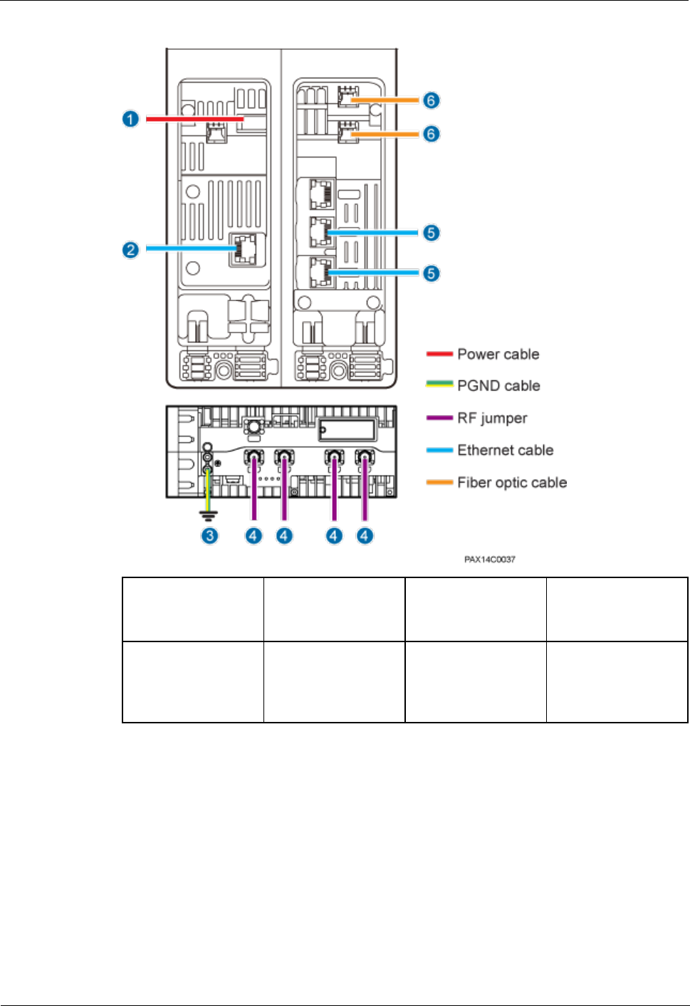
BTS3911E
Installation Guide
1 BTS3911E Installation Guide
Issue Draft A (2015-07-30)
Huawei Proprietary and Confidential
Copyright © Huawei Technologies Co., Ltd
23
Figure 1-17 BTS3911E cable connections
(1) External power
supply equipment
(2) External
monitored
equipment
(3) External ground
bar
(4) External antenna
system
(5) External
transmission
equipment or
cascaded BTS3911E
(6) External
transmission
equipment or
cascaded BTS3911E
-
-
1.8.3 Installing a PGND Cable
This section describes the procedure and precautions for installing a PGND cable.
Context
The length of a PGND cable must not exceed 30 m. When the required PGND cable is longer
than 30 m, deploy the ground bar nearer the BTS3911E. Table 1-2 lists the specifications of a
PGND cable.
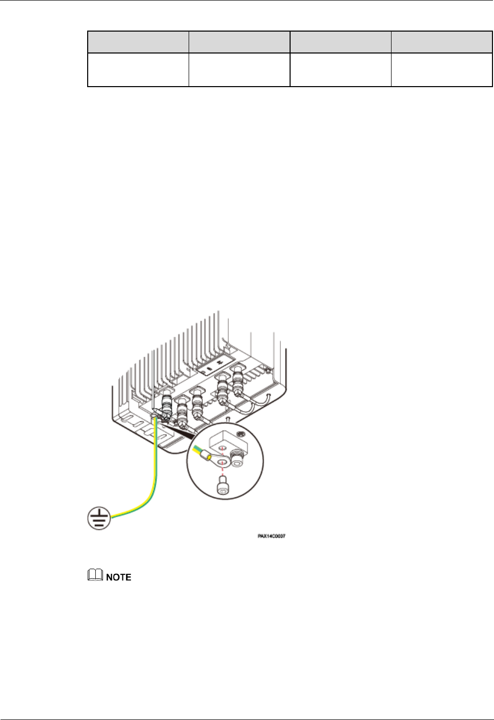
BTS3911E
Installation Guide
1 BTS3911E Installation Guide
Issue Draft A (2015-07-30)
Huawei Proprietary and Confidential
Copyright © Huawei Technologies Co., Ltd
24
Table 1-2 PGND cable specifications
Cable
One End
The Other End
Color
PGND cable
OT terminal (M6, 6
mm2)
OT terminal (M8, 6
mm2)
Yellowish green or
green
Procedure
Step 1 Make a PGND cable for the BTS3911E.
Cut the cable to the required length based on the actual cable route.
Add an OT terminal to each end of the PGND cable by following instructions provided
in section "Assembling the OT Terminal and the Power Cable" of Installation Reference.
Step 2 Install the PGND cable.
Connect the M6 OT terminal at one end of the PGND cable to the ground terminal at the
BTS3911E bottom and the M8 OT terminal at the other end to the external ground bar, as
shown in Figure 1-18.
Figure 1-18 Installing a PGND cable
When installing the PGND cable, crimp OT terminals in correct positions. See Figure 1-19.
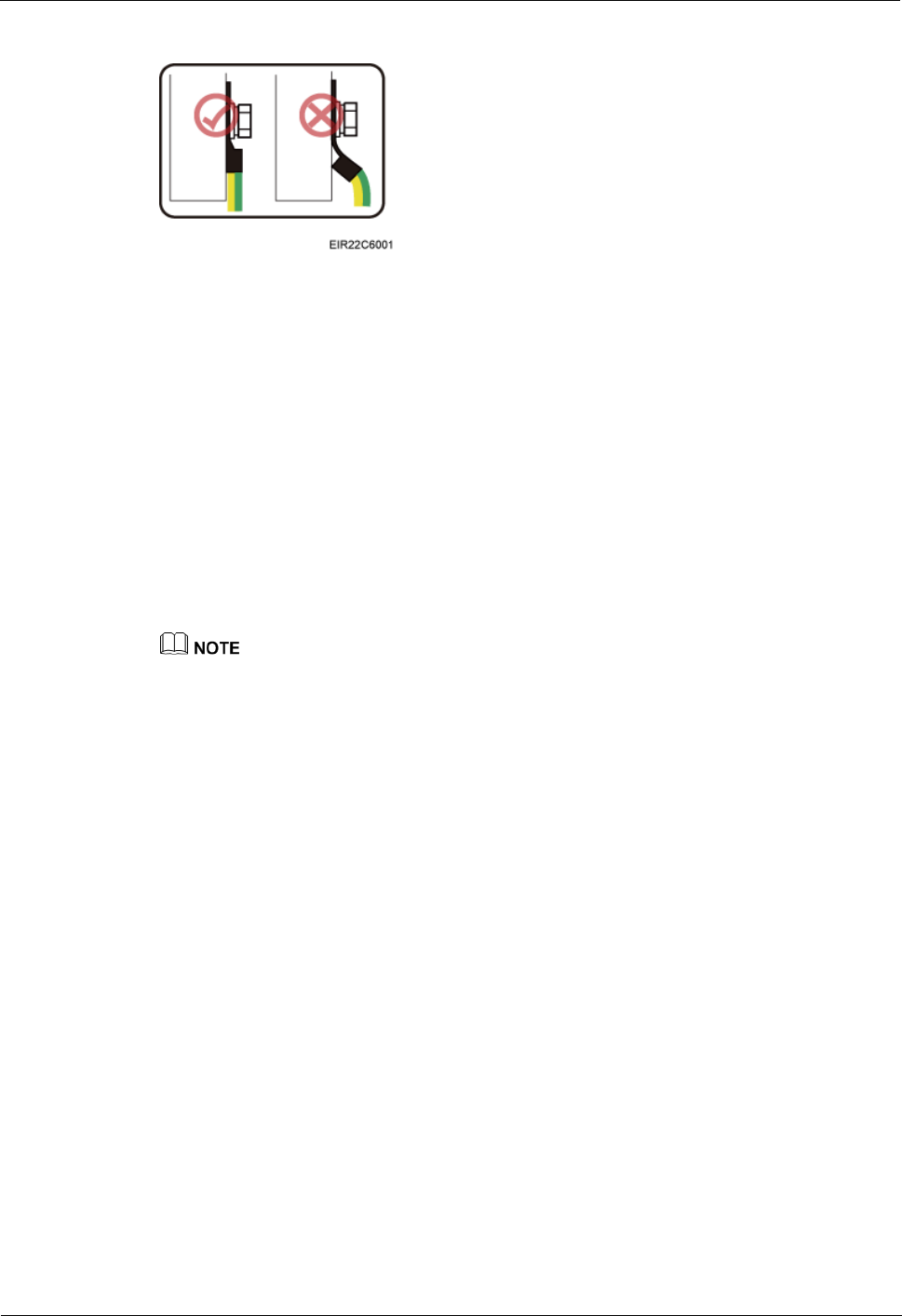
BTS3911E
Installation Guide
1 BTS3911E Installation Guide
Issue Draft A (2015-07-30)
Huawei Proprietary and Confidential
Copyright © Huawei Technologies Co., Ltd
25
Figure 1-19 Crimping an OT terminal
----End
Follow-up Procedure
Route the cable by following instructions provided in section 1.8.1 "Cabling Requirements"
and then use cable ties to bind the cable.
1.8.4 (Optional) Installing an RF Jumper
This section describes how to install an RF jumper for a BTS3911E. This operation is
required when the BTS3911E uses an external antenna.
Context
The cable route depends on actual requirements.
Procedure
Step 1 Connect the Smart-type N male connector at one end of the RF jumper to the RF port on the
BTS3911E.
Hold the metal part of the Smart-type N male connector and push the connector upwards. A
slight crack will be heard when the connector is properly installed. See Figure 1-20.
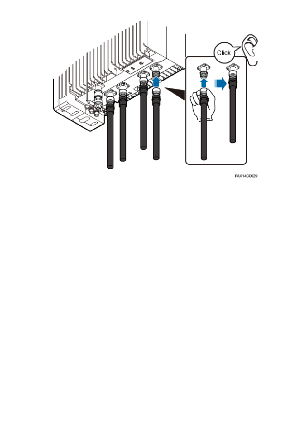
BTS3911E
Installation Guide
1 BTS3911E Installation Guide
Issue Draft A (2015-07-30)
Huawei Proprietary and Confidential
Copyright © Huawei Technologies Co., Ltd
26
Figure 1-20 Installing an RF jumper
Step 2 Connect the other end of the RF jumper to the external antenna system.
----End
Follow-up Procedure
Route the cable by following instructions provided in section 1.8.1 "Cabling Requirements"
and then use cable ties to bind the cable.
1.8.5 Opening the Maintenance Cavity Covers
This section describes the procedure and precautions for opening the maintenance cavity
covers of a BTS3911E.
Procedure
Step 1 Adjust the angles of the BTS3911E. See Figure 1-21.
Use an M10 hex key screwdriver to loosen the horizontal angle adjusting screw on the
top of the angle adjusting attachment plate. Adjust the horizontal angle of the BTS3911E
within the range of -18° to +18°.
Use the M10 hex key screwdriver to loosen the vertical angle adjusting screw on the top
of the angle adjusting mounting bracket. Adjust the vertical angle of the BTS3911E
within the range of -30° to +30°.
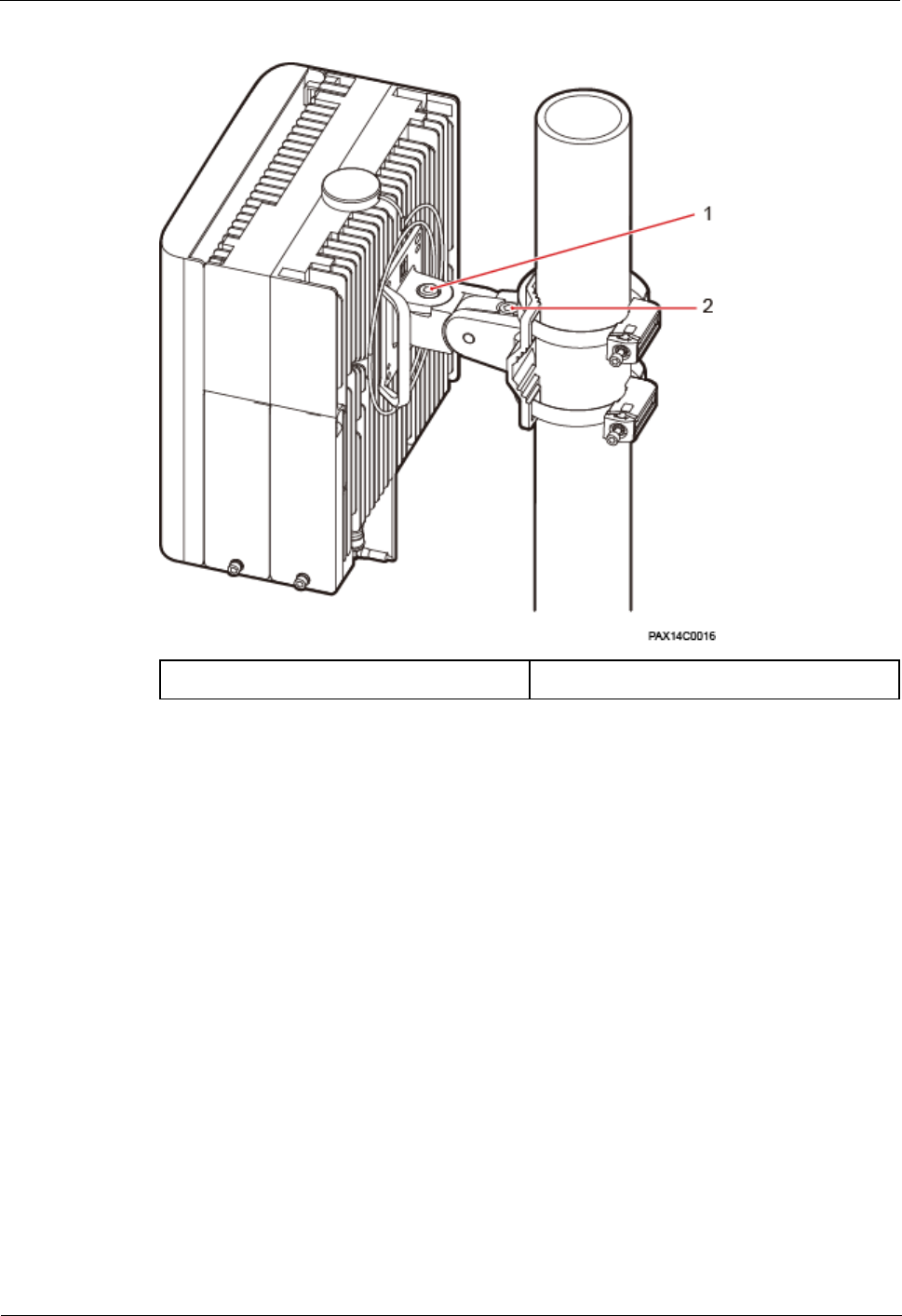
BTS3911E
Installation Guide
1 BTS3911E Installation Guide
Issue Draft A (2015-07-30)
Huawei Proprietary and Confidential
Copyright © Huawei Technologies Co., Ltd
27
Figure 1-21 Adjusting the angle of a BTS3911E
(1) Horizontal angle adjusting screw
(2) Vertical angle adjusting screw
Step 2 Use an M6 hex key screwdriver to loosen the captive screw on both the maintenance cavity
covers. Open the maintenance cavity covers.
Figure 1-22 shows the maintenance cavity structure.
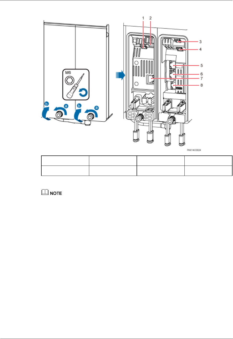
BTS3911E
Installation Guide
1 BTS3911E Installation Guide
Issue Draft A (2015-07-30)
Huawei Proprietary and Confidential
Copyright © Huawei Technologies Co., Ltd
28
Figure 1-22 Maintenance cavity structure
(1) CPRI
(2) PWR
(3) FE/GE3
(4) FE/GE2
(5) DBG
(6) FE/GE1
(7) EXT_ALM
(8) FE/GE0
When routing cables from a maintenance cavity, observe the following:
Route the power cable through an external cable hole.
Route the other cables through internal cable holes preferentially.
Step 3 Remove the waterproof blocks for the cables to be installed.
----End
1.8.6 Installing a Power Cable
This section describes the procedure and precautions for installing a power cable for a
BTS3911E. The power cable connects the BTS3911E and external power supply equipment.
Context
Table 1-3 lists the specifications of a power cable.

BTS3911E
Installation Guide
1 BTS3911E Installation Guide
Issue Draft A (2015-07-30)
Huawei Proprietary and Confidential
Copyright © Huawei Technologies Co., Ltd
29
Table 1-3 Power cable specifications
Cable
Color
One End
The Other
End
Remarks
Input power
cable for a
BTS3911E
L
Brown
Tool-less
female
connector
(pressfit type)
Depends on
the external
power supply
equipment.
Black jacket
N
Blue
PE
Yellowish
green
The color and structure of power cables vary with countries and regions. The power cables purchased
locally must conform to the local standards.
Procedure
Step 1 Make a power cable.
Cut the cable to a length suitable for the actual cable route.
Add a cord end terminal to one end of the cable by following instructions provided in
section 1.11.2 Assembling a Tool-less Female Connector (Pressfit Type) and a Power
Cable. At the other end, add a terminal that matches the external power supply
equipment.
Step 2 Installing the power cable. Connect the terminal of the power cable to the PWR port on the
BTS3911E. See Figure 1-23.
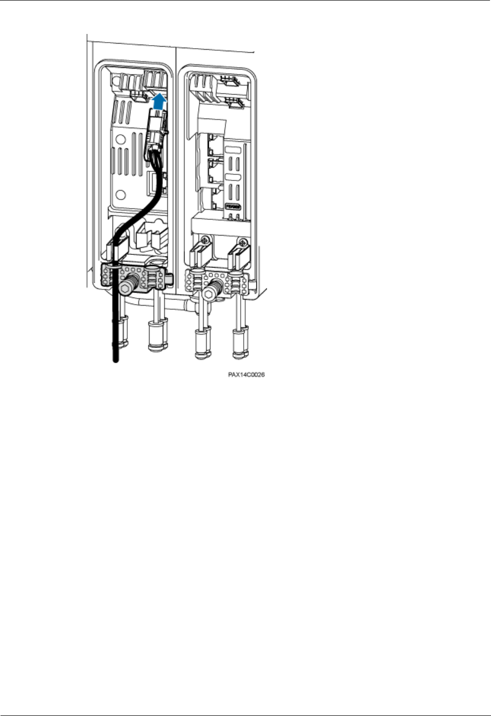
BTS3911E
Installation Guide
1 BTS3911E Installation Guide
Issue Draft A (2015-07-30)
Huawei Proprietary and Confidential
Copyright © Huawei Technologies Co., Ltd
30
Figure 1-23 Installing a power cable
----End
Follow-up Procedure
Route the cable by following instructions provided in section 1.8.1 "Cabling Requirements"
and then use cable ties to bind the cable.
1.8.7 Installing an Alarm Cable
This section describes the procedure and precautions for installing an alarm cable.
Procedure
Step 1 Make an alarm cable.
1. Add an RJ45 connector to one end of the alarm cable by following instructions provided
in section 1.11.3 Assembling a Shielded RJ45 Connector and an Ethernet Cable.
2. Check whether the made RJ45 connector is qualified by following instructions in section
"Checking the Appearance of Metal Contact Strips" of Installation Reference.
3. Repeat the preceding two steps to add an RJ45 connector to the other end of the alarm
cable.
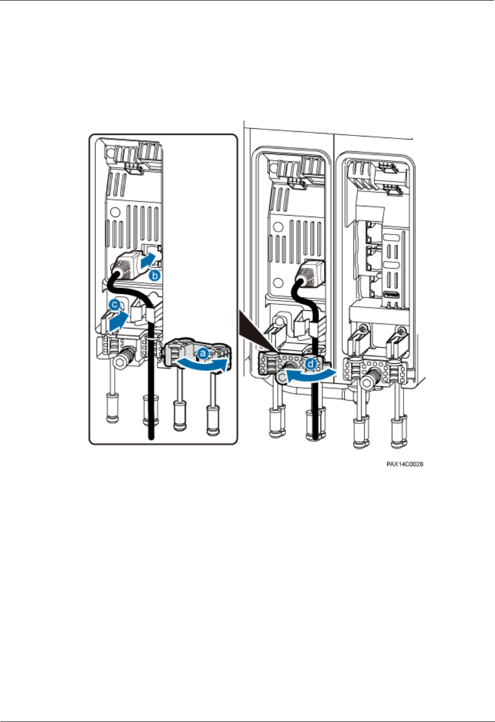
BTS3911E
Installation Guide
1 BTS3911E Installation Guide
Issue Draft A (2015-07-30)
Huawei Proprietary and Confidential
Copyright © Huawei Technologies Co., Ltd
31
4. Test the continuity of each contact point of the cable and check that the cable is correctly
and securely connected by following instructions in section "Testing the Connection of
Assembled Cables" of Installation Reference.
Step 2 Connect one end of the alarm cable to the EXT_ALM port on the BTS3911E and the other
end to the external monitored equipment. See Figure 1-24.
Figure 1-24 Installing an alarm cable
----End
Follow-up Procedure
Route the cable by following instructions provided in section 1.8.1 "Cabling Requirements"
and then use cable ties to bind the cable.
1.8.8 Installing Transmission Cables
This section describes the procedure and precautions for installing transmission cables.
1.8.8.1 Installing an FE/GE Fiber Optic Cable
This section describes the procedure and precautions for installing an FE/GE fiber optic cable.
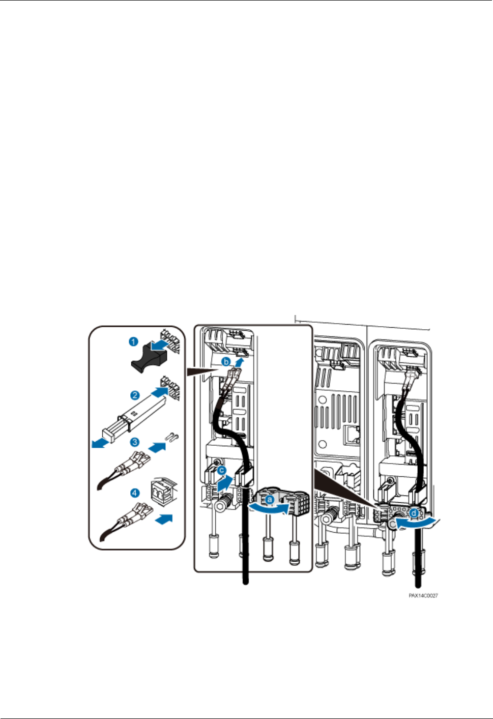
BTS3911E
Installation Guide
1 BTS3911E Installation Guide
Issue Draft A (2015-07-30)
Huawei Proprietary and Confidential
Copyright © Huawei Technologies Co., Ltd
32
Context
The single-mode optical modules to be installed must match the data rate at the optical
ports.
Do not twist, bend, stretch, or squeeze fiber optic cables during installation.
Long-time exposure to the air causes performance exceptions on an optical module.
Therefore, optical modules must be connected to fiber optic cables within 20 minutes
after being unpacked.
The cable route depends on actual requirements.
One end of a fiber optic cable can be connected to the FE/GE2 or FE/GE3 port on the
BTS3911E. Connection to the FE/GE2 port is preferred.
Procedure
Step 1 Remove the dustproof cap from the FE/GE2 or FE/GE3 port. Keep the cap secure.
Step 2 Insert an optical module into the FE/GE2 or FE/GE3 port, and remove the dustproof cap from
the optical module.
Step 3 Remove the dustproof cap from the optical fiber connector, tidy the optical fibers, and insert
the DLC connector into the optical module. See Figure 1-25.
Figure 1-25 Installing a fiber optic cable
----End
Follow-up Procedure
Route the cable by following instructions provided in section 1.8.1 "Cabling Requirements"
and then use cable ties to bind the cable.

BTS3911E
Installation Guide
1 BTS3911E Installation Guide
Issue Draft A (2015-07-30)
Huawei Proprietary and Confidential
Copyright © Huawei Technologies Co., Ltd
33
1.8.8.2 Installing an FE/GE Ethernet Cable
This section describes the procedure and precautions for installing an FE/GE Ethernet cable.
Context
An FE/GE Ethernet cable must be a shielded straight-through cable.
One end of an FE/GE Ethernet cable can be connected to the FE/GE0 or FE/GE1 port on the
BTS3911E. Connection to the FE/GE0 port is preferred.
Procedure
Step 1 Make an FE/GE Ethernet cable.
1. Add an RJ45 connector to one end of the FE/GE Ethernet cable by following instructions
in section 1.11.3 Assembling a Shielded RJ45 Connector and an Ethernet Cable.
2. Check whether the made RJ45 connector is qualified by following instructions in section
"Checking the Appearance of Metal Contact Strips" of Installation Reference.
3. Repeat the preceding two steps to add an RJ45 connector to the other end of the FE/GE
Ethernet cable.
4. Test the continuity of each contact point of the cable and check that the cable is correctly
and securely connected by following instructions in section "Testing the Connection of
Assembled Cables" of Installation Reference.
Step 2 Install the FE/GE Ethernet cable. See Figure 1-26.
Connect one end of the Ethernet cable to the FE/GE0 or FE/GE1 port in the BTS3911E
maintenance cavity and the other end to the external transmission equipment.
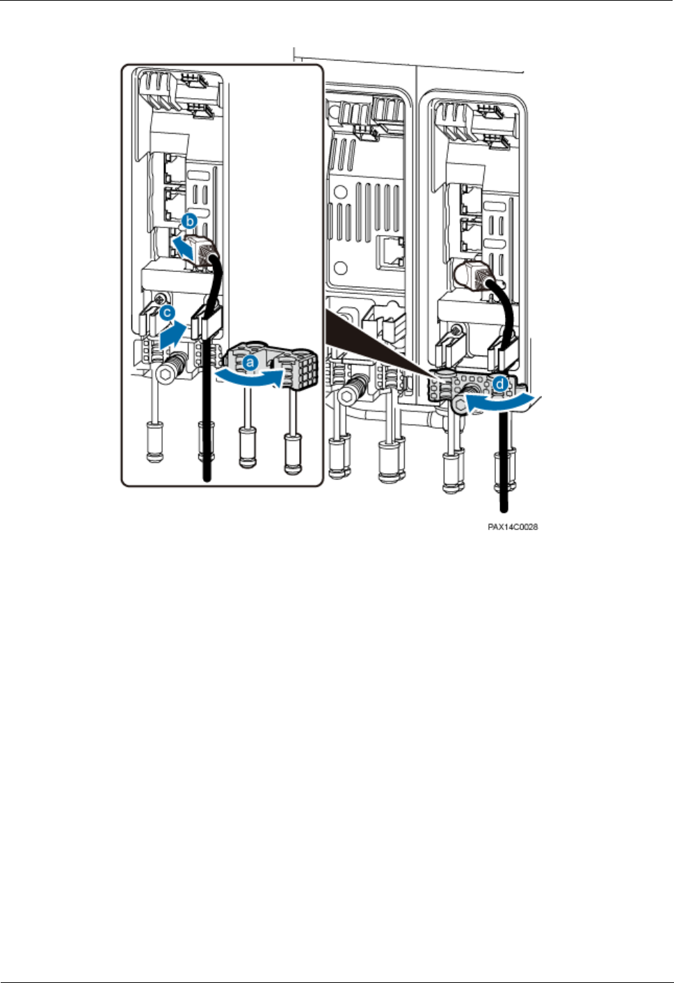
BTS3911E
Installation Guide
1 BTS3911E Installation Guide
Issue Draft A (2015-07-30)
Huawei Proprietary and Confidential
Copyright © Huawei Technologies Co., Ltd
34
Figure 1-26 Installing an FE/GE Ethernet cable
----End
Follow-up Procedure
Route the cable by following instructions provided in section 1.8.1 "Cabling Requirements"
and then use cable ties to bind the cable.
1.8.8.3 (Optional) Installing an FE/GE Fiber Optic Cable for Cascading
This section describes the procedure and precautions for installing an FE/GE fiber optic cable
used for cascading two BTS3911Es.
Context
The single-mode optical modules to be installed must match the data rate at the optical
ports.
Do not twist, bend, stretch, or squeeze fiber optic cables during installation.
Long-time exposure to the air causes performance exceptions on an optical module.
Therefore, optical modules must be connected to fiber optic cables within 20 minutes
after being unpacked.
The cable route depends on actual requirements.
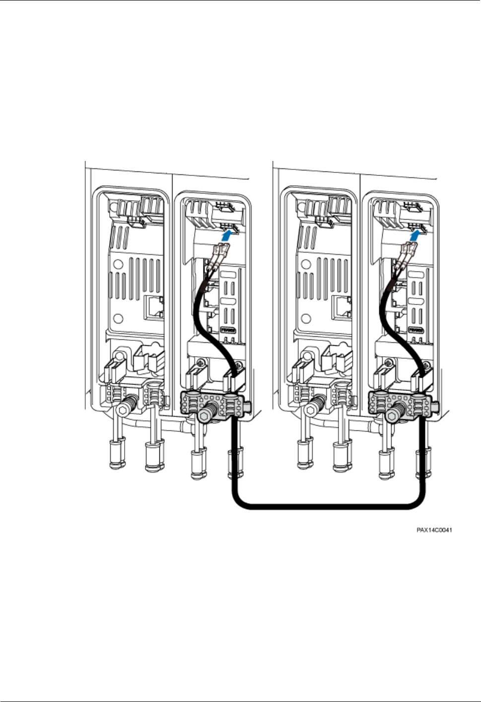
BTS3911E
Installation Guide
1 BTS3911E Installation Guide
Issue Draft A (2015-07-30)
Huawei Proprietary and Confidential
Copyright © Huawei Technologies Co., Ltd
35
Procedure
Step 1 For both BTS3911Es, remove the dustproof cap from the FE/GE2 or FE/GE3 port. Keep the
caps secure.
Step 2 For both BTS3911Es, insert an optical module into the FE/GE2 or FE/GE3 port, and remove
the dustproof cap from the optical module.
Step 3 Remove the dustproof cap from the optical fiber connector, tidy the optical fibers, and insert
the DLC connector into the optical module. See Figure 1-27.
Figure 1-27 Installing a fiber optic cable for cascading
----End
Follow-up Procedure
Route the cable by following instructions provided in section 1.8.1 "Cabling Requirements"
and then use cable ties to bind the cable.

BTS3911E
Installation Guide
1 BTS3911E Installation Guide
Issue Draft A (2015-07-30)
Huawei Proprietary and Confidential
Copyright © Huawei Technologies Co., Ltd
36
1.8.8.4 (Optional) Installing an FE/GE Ethernet Cable for Cascading
This section describes the procedure and precautions for installing an FE/GE Ethernet cable
used for cascading two BTS3911Es.
Context
An FE/GE Ethernet cable must be a shielded straight-through cable.
Procedure
Step 1 Make an FE/GE Ethernet cable.
1. Add an RJ45 connector to one end of the FE/GE Ethernet cable by following instructions
in section 1.11.3 Assembling a Shielded RJ45 Connector and an Ethernet Cable.
2. Check whether the made RJ45 connector is qualified by following instructions in section
"Checking the Appearance of Metal Contact Strips" of Installation Reference.
3. Repeat the preceding two steps to add an RJ45 connector to the other end of the FE/GE
Ethernet cable.
4. Test the continuity of each contact point of the cable and check that the cable is correctly
and securely connected by following instructions in section "Testing the Connection of
Assembled Cables" of Installation Reference.
Step 2 Install the FE/GE Ethernet cable.
Connect one end of the Ethernet cable to the FE/GE0 or FE/GE1 port on one BTS3911E and
the other end to the FE/GE0 or FE/GE1 port on the other BTS3911E. See Figure 1-28.
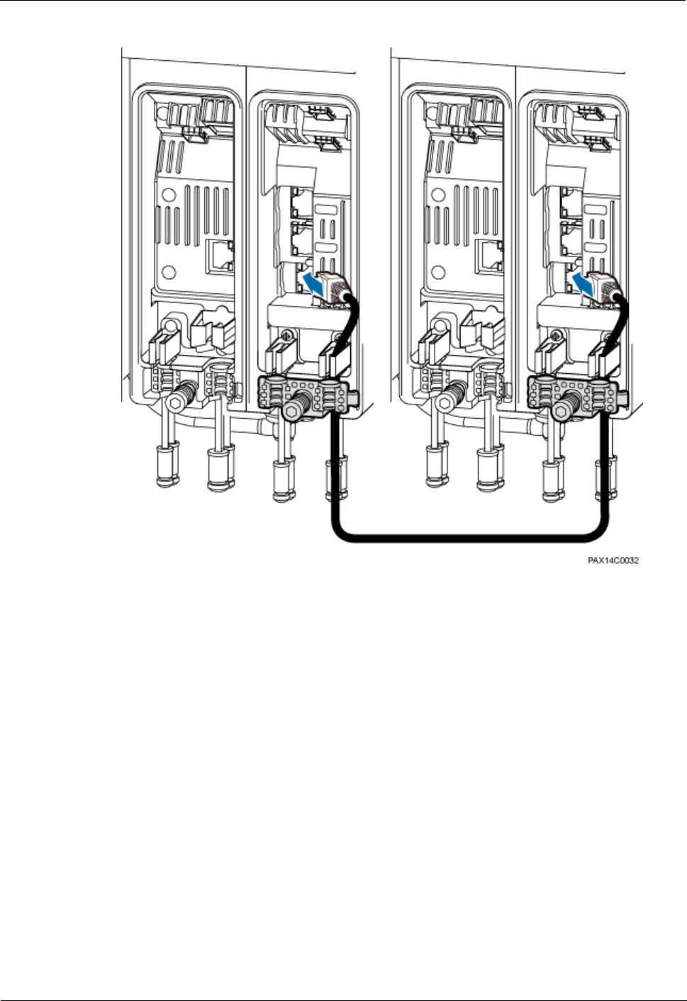
BTS3911E
Installation Guide
1 BTS3911E Installation Guide
Issue Draft A (2015-07-30)
Huawei Proprietary and Confidential
Copyright © Huawei Technologies Co., Ltd
37
Figure 1-28 Installing an FE/GE cable
----End
Follow-up Procedure
Route the cable by following instructions provided in section 1.8.1 "Cabling Requirements"
and then use cable ties to bind the cable.
1.8.9 Closing the Maintenance Cavity Covers
This section describes the procedure and precautions for closing the maintenance cavity
covers of a BTS3911E.
Procedure
Step 1 Insert waterproof blocks into vacant cable troughs in both the cabling cavities. See Figure 1-
29.
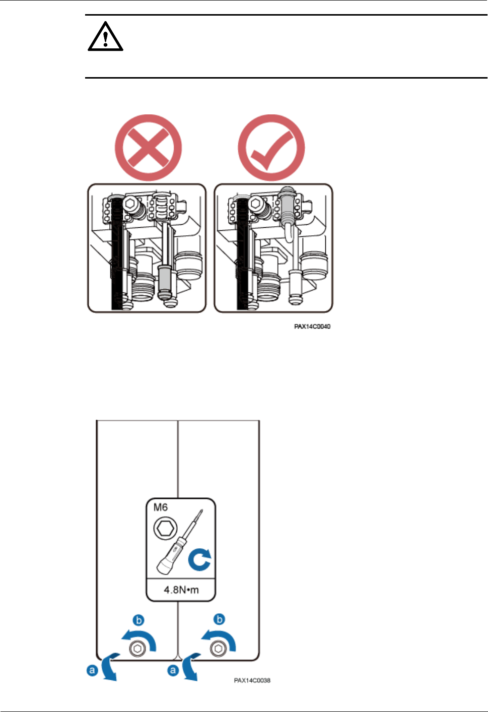
BTS3911E
Installation Guide
1 BTS3911E Installation Guide
Issue Draft A (2015-07-30)
Huawei Proprietary and Confidential
Copyright © Huawei Technologies Co., Ltd
38
CAUTION
Ensure that cables or waterproof blocks are properly inserted into troughs.
Figure 1-29 Checking that vacant cable troughs are properly waterproofed
Step 2 Close the maintenance cavity covers of the BTS3911E. Use an M6 hex key screwdriver to
torque the screws on the covers to 4.8 N·m. See Figure 1-30.
Figure 1-30 Closing the maintenance cavity covers
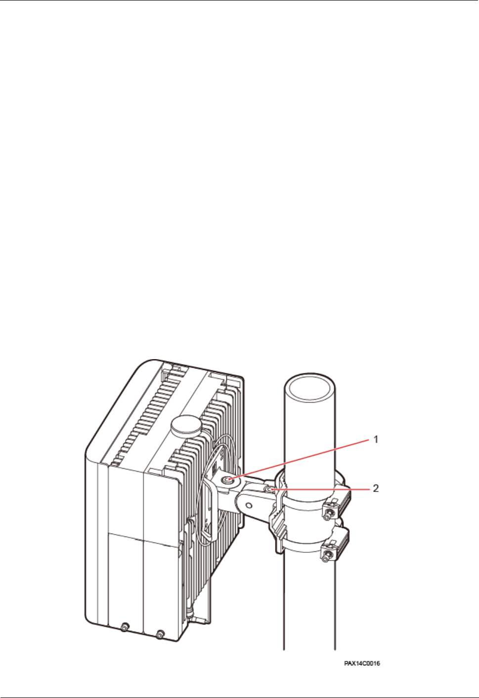
BTS3911E
Installation Guide
1 BTS3911E Installation Guide
Issue Draft A (2015-07-30)
Huawei Proprietary and Confidential
Copyright © Huawei Technologies Co., Ltd
39
----End
1.8.10 Adjusting Installation Angles
This section describes the procedure and precautions for adjusting the installation angles of a
BTS3911E.
Context
After a BTS3911E and its cables are installed, adjust its installation angles through the angle
adjusting attachment plate and mounting bracket within a range of -30° to +30° in the
horizontal and -18° to +18° in the vertical.
Procedure
Step 1 Adjust the installation angles of the BTS3911E. See Figure 1-31.
Adjust the horizontal angle: Use an M10 hex key screwdriver to loosen the angle
adjusting screw on the top of the angle adjusting attachment plate. Hold the BTS3911E,
properly adjust the horizontal angle, and torque the angle adjusting screw to 7 N·m.
Adjust the vertical angle: Use the M10 hex key screwdriver to loosen the angle adjusting
screw on the top of the angle adjusting mounting bracket. Hold the BTS3911E, properly
adjust the vertical angle, and torque the angle adjusting screw to 7 N·m.
Figure 1-31 Adjusting the installation angles of a BTS3911E
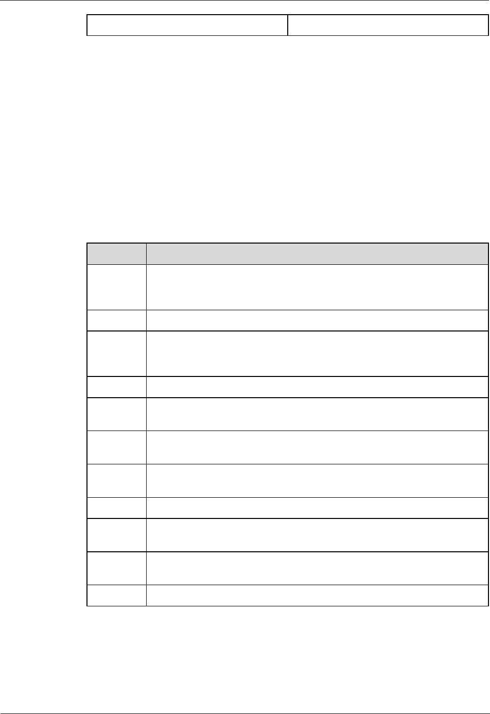
BTS3911E
Installation Guide
1 BTS3911E Installation Guide
Issue Draft A (2015-07-30)
Huawei Proprietary and Confidential
Copyright © Huawei Technologies Co., Ltd
40
(1) Horizontal angle adjusting screw
(2) Vertical angle adjusting screw
Step 2 Ensure that the horizontal and vertical angle adjusting screws have been secured.
Step 3 Record the horizontal and vertical angles.
----End
1.9 Checking the Hardware Installation
This section describes how to check the hardware installation after a BTS3911E is installed.
Table 1-4 provides the checklist for the BTS3911E hardware installation.
Table 1-4 BTS3911E hardware installation checklist
SN
Item
1
The installation position conforms to the engineering drawing and meets the
clearance requirements. Sufficient space is reserved for equipment
maintenance.
2
The BTS3911E is securely installed, and the screws are tightened.
3
In wall-mounted scenarios, the mounting holes on the mounting bracket are
well aligned with those of the expansion bolts. In addition, the mounting
bracket is secured on the wall evenly and steadily.
4
In pole-mounted scenarios, the mounting bracket is secured on the pole.
5
The angle adjustment error of the BTS3911E is less than 3° in the horizontal
direction and is not more than 3° in the vertical direction.
6
Vacant cable troughs in both maintenance cavities are covered with
waterproof blocks, and the maintenance cavity covers are fastened.
7
None of power cables and PGND cables are short-circuited, reversely
connected, damaged, or broken.
8
Power cables and PGND cables are separately bound from other cables.
9
All modules are connected using equipotential cables and then connected to
the closest ground bar by using PGND cables.
10
The connectors of each signal cable are intact and securely linked, and these
cables are not damaged or broken.
11
Labels are correct, legible, and complete at both ends of each cable.
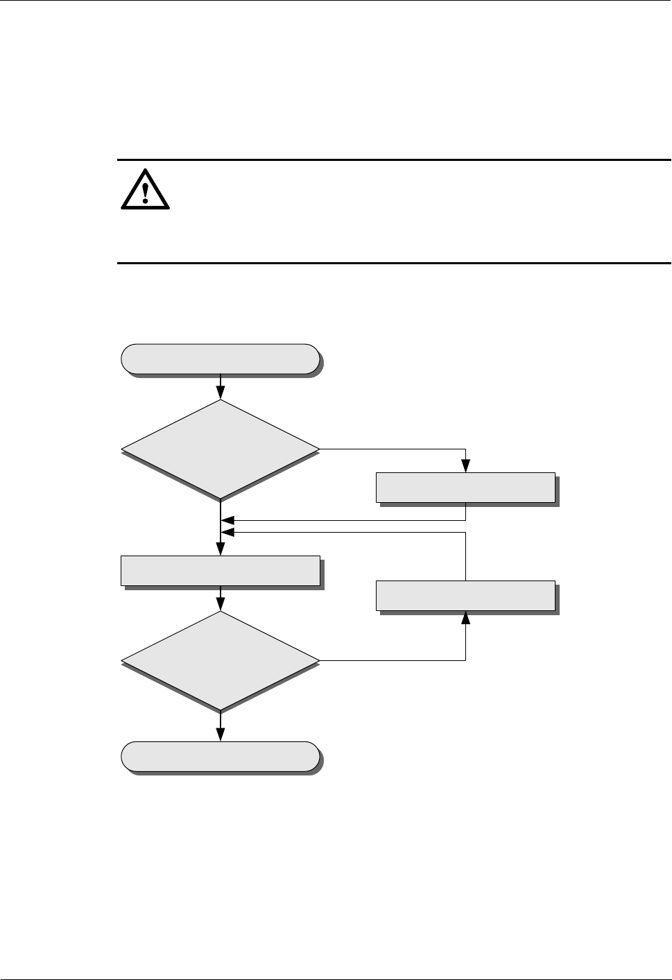
BTS3911E
Installation Guide
1 BTS3911E Installation Guide
Issue Draft A (2015-07-30)
Huawei Proprietary and Confidential
Copyright © Huawei Technologies Co., Ltd
41
1.10 Performing a Power-On Check
This section describes the procedure for performing a power-on check on a BTS3911E.
Context
CAUTION
After a BTS3911E is unpacked, power it on within 24 hours. If the BTS3911E is powered off
for maintenance, restore power to it within 24 hours.
Figure 1-32 shows the BTS3911E power-on check procedure.
Figure 1-32 Power-on check
IPP02C0002
Start
Are cable
connections correct?
Power on the BTS3911E.
Is the indicator status
normal?
End
Correct the connections.
Rectify the fault.
Yes
Yes
No
No
Procedure
Step 1 Check that the cables are correctly connected.
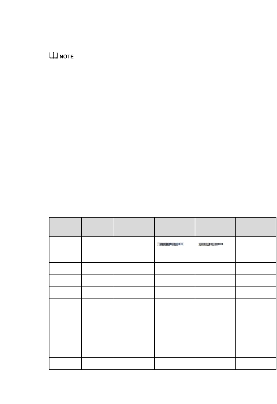
BTS3911E
Installation Guide
1 BTS3911E Installation Guide
Issue Draft A (2015-07-30)
Huawei Proprietary and Confidential
Copyright © Huawei Technologies Co., Ltd
42
Step 2 Check that the input voltage of the BTS3911E is 110 V AC or 220 V AC, and the frequency
ranges from 50 Hz to 60 Hz.
Step 3 Power on the BTS3911E. Wait 3 to 5 minutes and then observe the indicator status of the
BTS3911E. If the RUN indicator blinks (on for 1s and off for 1s) and the ALM indicator is
off, the BTS3911E is working properly.
A BTS3911E takes about 3 minutes to complete the startup procedure, during which the indicator
status is negligible.
During a startup, a BTS3911E reads and writes the flash memory and therefore the indicators
blinking quickly may blink irregularly for 1s to 2s, which does not affect services.
----End
1.11 References
This section describes reference information and common operations involved during
installation.
1.11.1 SN Collection Template
This section describes the SN collection template for BTS3911Es.
The SN collection template is used to record information of BTS3911Es at the initial
installation stage to facilitate subsequent commissioning and maintenance. Table 1-5 provides
the template.
Table 1-5 SN collection template
No.
Site
Number
Site Name
Base Station
SN
ODM04A
SN
Location
Information
Sample
xx
BTS3911E
xx floor, xx
building, xx
mansion
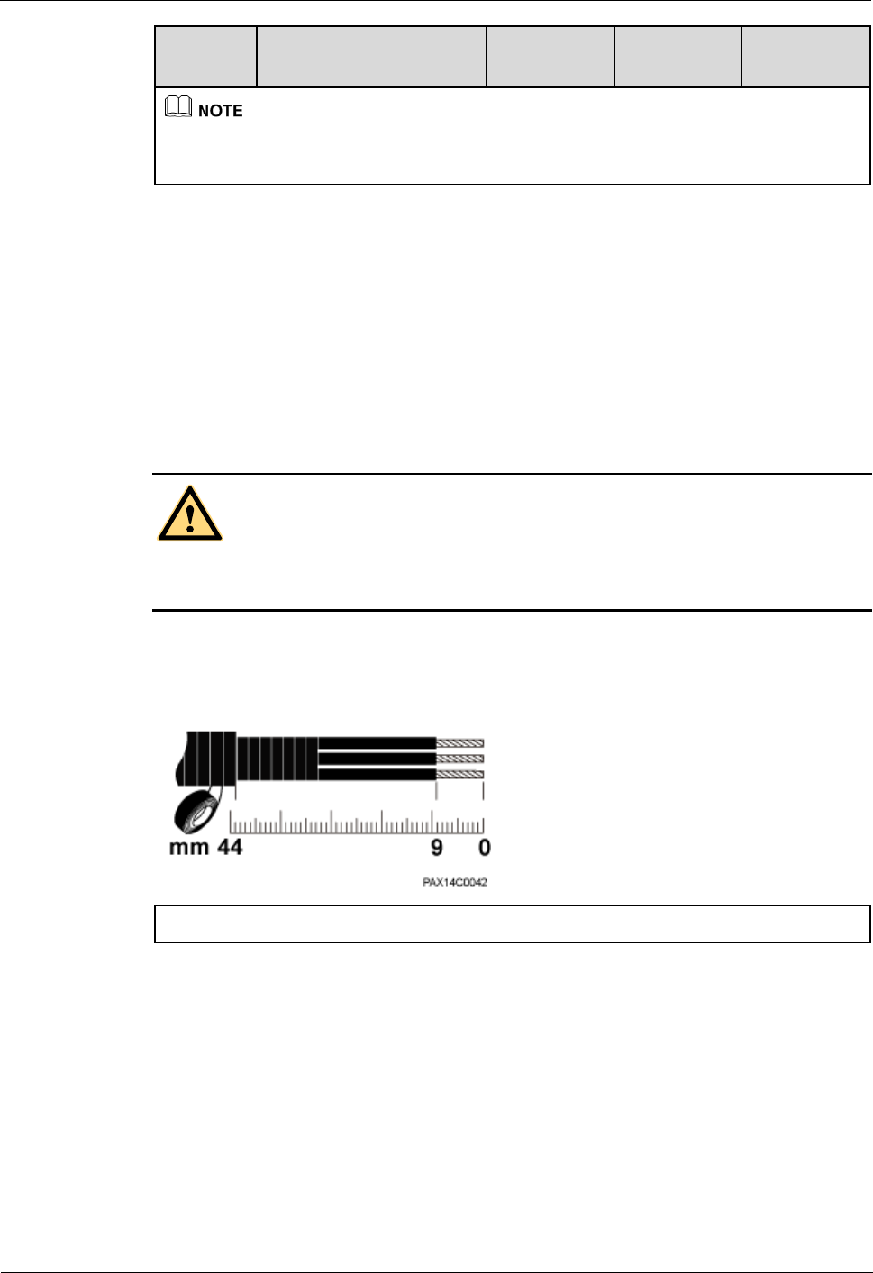
BTS3911E
Installation Guide
1 BTS3911E Installation Guide
Issue Draft A (2015-07-30)
Huawei Proprietary and Confidential
Copyright © Huawei Technologies Co., Ltd
43
No.
Site
Number
Site Name
Base Station
SN
ODM04A
SN
Location
Information
The SN collection template defines the radio network to access and is essential to engineering and
subsequent maintenance, especially when multiple devices are installed at a short distance. Carefully
maintain this template.
1.11.2 Assembling a Tool-less Female Connector (Pressfit Type)
and a Power Cable
This section describes the procedure for making a tool-less female connector (pressfit type)
for a BTS3911E power cable.
Context
DANGER
Strictly follow the procedure described herein to make a tool-less female connector (pressfit
type). Any incompliance may cause damage to the BTS3911E or personal injuries.
Figure 1-33 shows the scale for making a power cable for the BTS3911E.
Figure 1-33 BTS3911E power cable-making scale
(1) BTS3911E power cable-making scale
Procedure
Step 2 Unwind the required length of the power cable for different operations based on the scale. See
Figure 1-34.
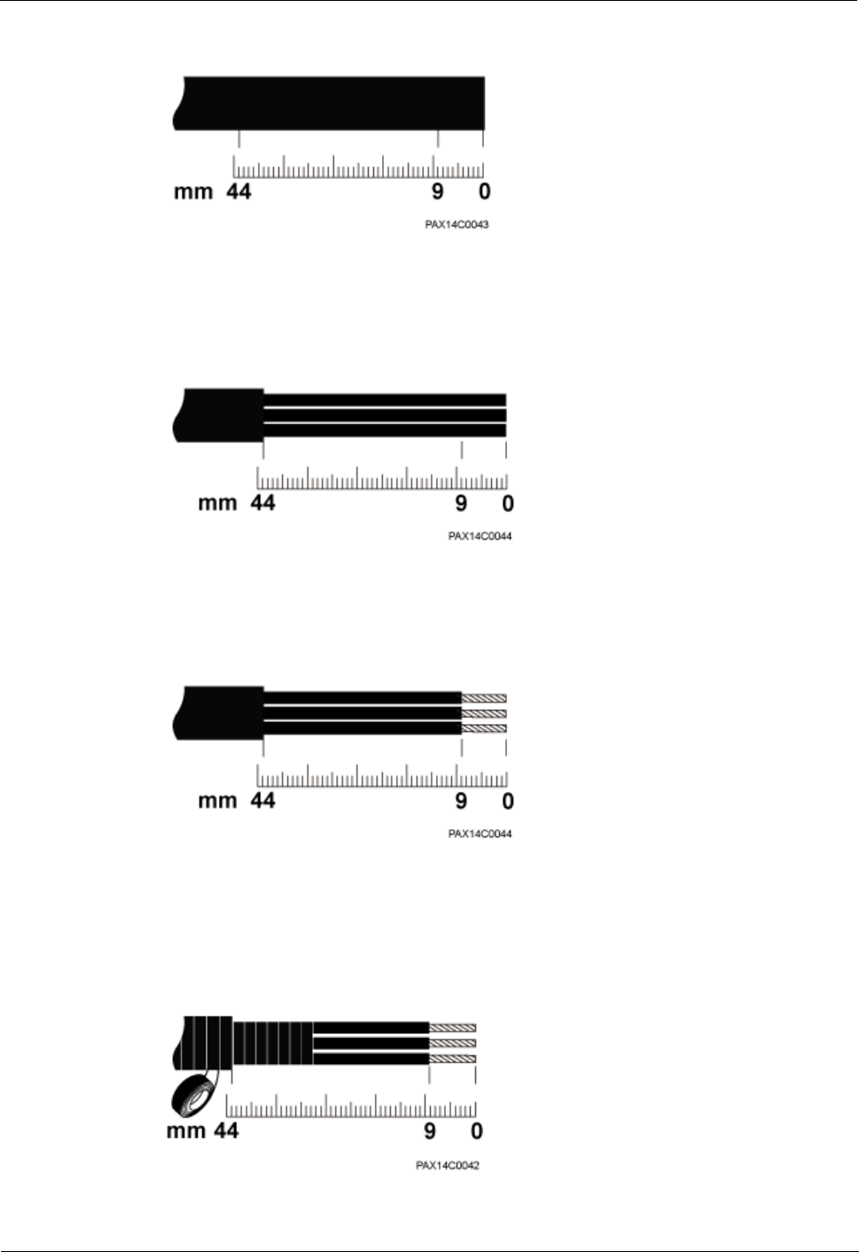
BTS3911E
Installation Guide
1 BTS3911E Installation Guide
Issue Draft A (2015-07-30)
Huawei Proprietary and Confidential
Copyright © Huawei Technologies Co., Ltd
44
Figure 1-34 Determining the power cable length
Step 3 Remove the outer jacket of the power cable. See Figure 1-35.
Figure 1-35 Removing the outer jacket of a cable
Step 4 Remove the outer jacket of each core wire. The length of the removed outer jacket must
match the tool-less female connector (pressfit type). See Figure 1-36.
Figure 1-36 Removing the outer jacket of core wires
Step 5 Use PVC insulation tapes to wrap the outer jackets of the three core wires and the adjacent
section of the AC power cable. See Figure 1-37.
Figure 1-37 Insulating a power cable
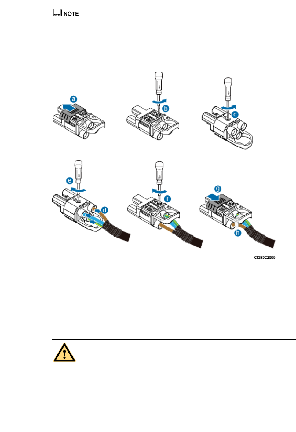
BTS3911E
Installation Guide
1 BTS3911E Installation Guide
Issue Draft A (2015-07-30)
Huawei Proprietary and Confidential
Copyright © Huawei Technologies Co., Ltd
45
It is good practice to wrap the three core wires for 16 mm and the adjacent section of the AC power
cable section for about 10 mm.
Step 6 Assemble a tool-less female connector (pressfit type) and the three core wires. See Figure 1-
38.
Figure 1-38 Adding a tool-less female connector (pressfit type) to core wires
1. Push the sliding block on the connector outwards along the arrow direction.
2. Use an M3 Phillips torque screwdriver to loosen the two screws.
3. Use the M3 Phillips torque screwdriver to loosen the screw on the other side.
4. Insert the brown core wire into the L port, the blue core wire into the N port, and the
yellowish green core wire to the PE port.
DANGER
Ensure that the positive and negative wires of all power cables are correctly connected. Any
incorrect power cable connection (such as reverse polarity connection) may cause damage to
equipment or unexpected personal injuries.
5. Use the M3 Phillips torque screwdriver to torque the screws on both sides to 0.5 N·m.
6. Push the sliding block back in position along the arrow direction.
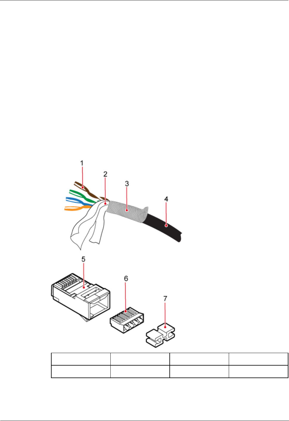
BTS3911E
Installation Guide
1 BTS3911E Installation Guide
Issue Draft A (2015-07-30)
Huawei Proprietary and Confidential
Copyright © Huawei Technologies Co., Ltd
46
7. Use cable ties to bind the core wires to the connector.
Step 7 Gently pull each core wire to check that the connections are secure. The core wires can
remain fastened under external force of 30 N. Ensure that all copper wires are inserted into the
wiring terminal sockets and no copper wire is exposed outside the connector.
----End
1.11.3 Assembling a Shielded RJ45 Connector and an Ethernet
Cable
This section describes how to assemble a shielded RJ45 connector and an Ethernet cable. A
straight-through cable is used as an example.
Context
Figure 1-39 shows the components of an RJ45 connector and an Ethernet cable.
Figure 1-39 Components of an RJ45 connector and an Ethernet cable
(1) Core wire
(2) Aluminum foil
(3) Braided layer
(4) Outer jacket
(5) RJ45 connector
(6) Load bar
(7) Wire holder
-
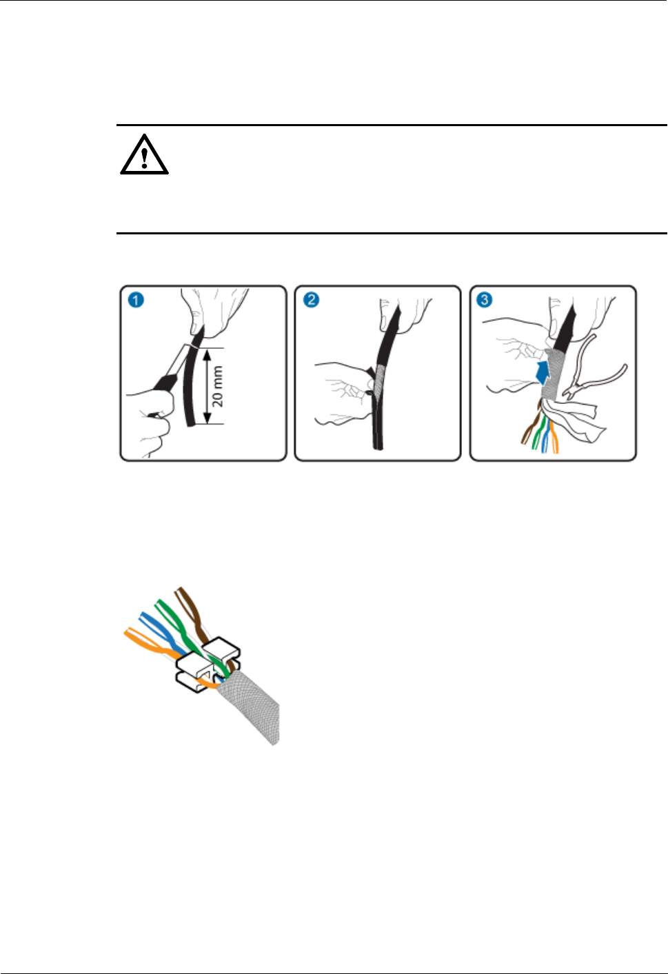
BTS3911E
Installation Guide
1 BTS3911E Installation Guide
Issue Draft A (2015-07-30)
Huawei Proprietary and Confidential
Copyright © Huawei Technologies Co., Ltd
47
Procedure
Step 1 Remove the outer jacket (20 mm) of the Ethernet cable, tip back the braided layer, and cut off
the aluminum foil and guard space. See Figure 1-40.
CAUTION
Do not damage the shield layer when removing the jacket.
Do not damage the insulation layer of the Ethernet cable when removing the shield layer.
Figure 1-40 Removing the jacket of an Ethernet cable
Step 2 Arrange core wires in the sequence shown in Figure 1-41 and secure the wire holder to the
bottom of core wires.
Figure 1-41 Securing the wire holder to the bottom of core wires
Step 3 Pinch the core wires into the load bar, as shown in Figure 1-42. Table 1-6 describes mapping
between the core wires and pins of the RJ45 connector.
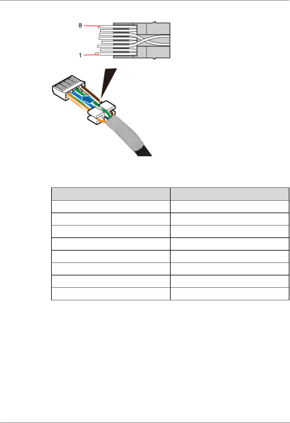
BTS3911E
Installation Guide
1 BTS3911E Installation Guide
Issue Draft A (2015-07-30)
Huawei Proprietary and Confidential
Copyright © Huawei Technologies Co., Ltd
48
Figure 1-42 Leading core wires through the load bar
Table 1-6 Pin assignment
Pin SN
Wire Color
1
White and orange
2
Orange
3
White and green
4
Blue
5
White and blue
6
Green
7
White and brown
8
Brown
After pinching the core wires through the load bar, push the load bar along the core wires to
the bottom of the wire holder, and evenly cut off the excess part of the core wires. See Figure
1-43.
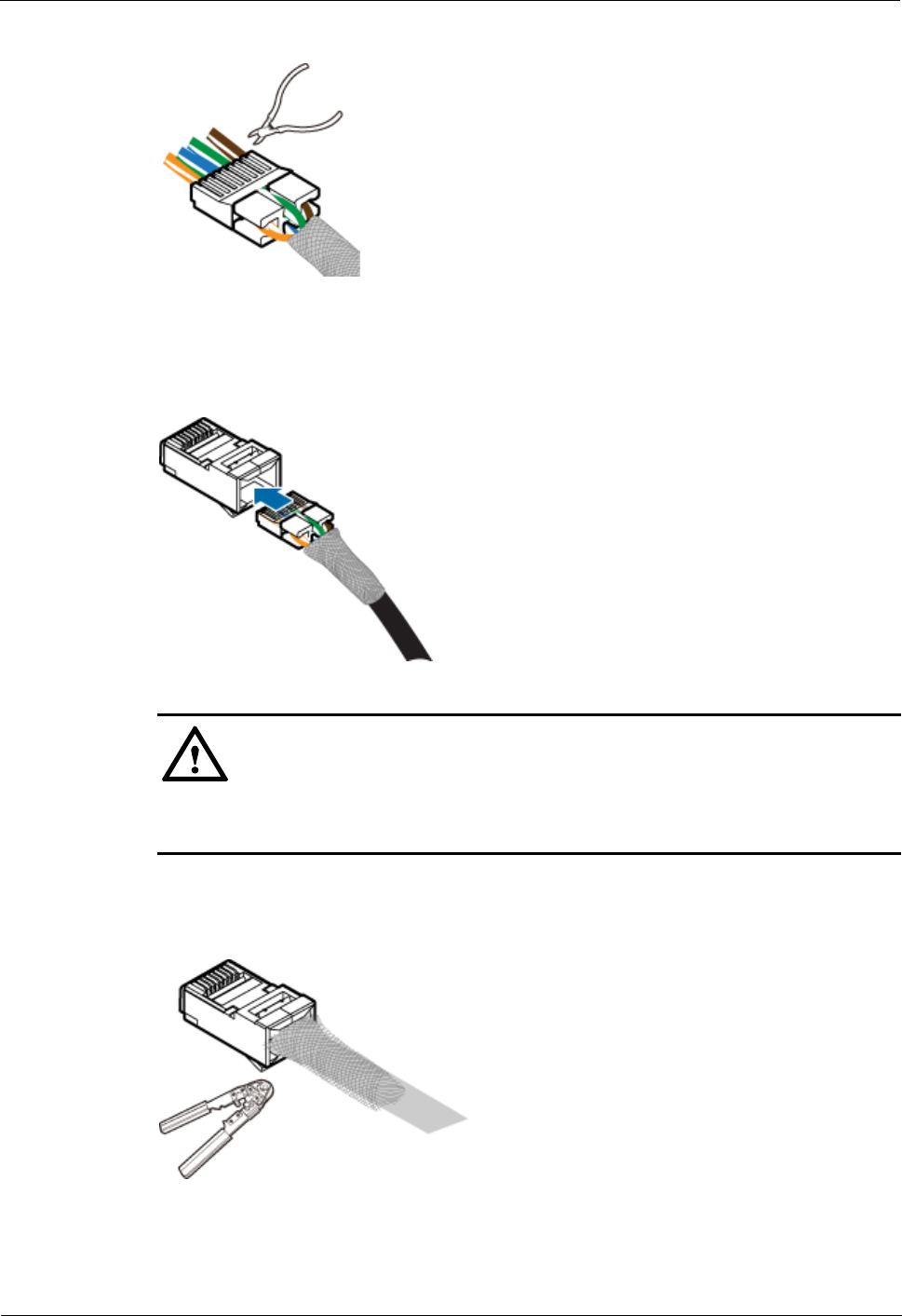
BTS3911E
Installation Guide
1 BTS3911E Installation Guide
Issue Draft A (2015-07-30)
Huawei Proprietary and Confidential
Copyright © Huawei Technologies Co., Ltd
49
Figure 1-43 Cutting off the excess part of core wires
Step 4 Insert the load bar into the RJ45 connector. See Figure 1-44.
Figure 1-44 Inserting the load bar into the RJ45 connector
CAUTION
Observe the side or front of the RJ45 connector and ensure that the core wires are inserted to
the bottom of the RJ45 connector.
Step 5 Use a crimping tool to crimp the connector. See Figure 1-45.
Figure 1-45 Crimping the connector
Step 6 Use a cable cutter to evenly cut off the protruding braided layer of the connector along the
wire holder. See Figure 1-46.
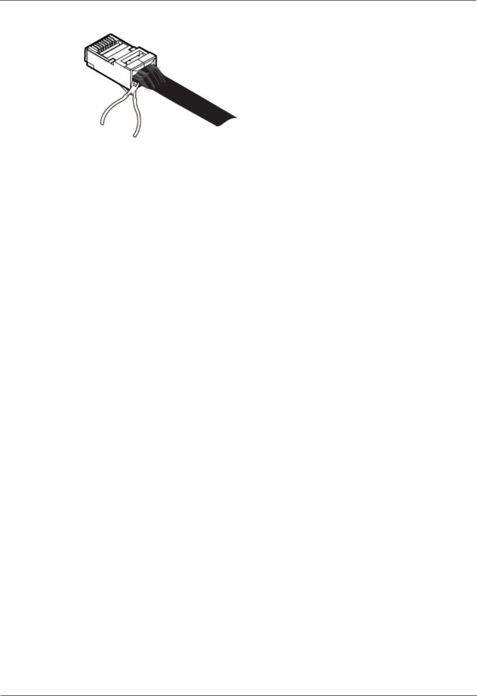
BTS3911E
Installation Guide
1 BTS3911E Installation Guide
Issue Draft A (2015-07-30)
Huawei Proprietary and Confidential
Copyright © Huawei Technologies Co., Ltd
50
Figure 1-46 Cutting off the excess braided layer
----End

BTS3911E
V100R011C00
Site Maintenance Guide
Issue
Draft A
Date
2015-07-30
HUAWEI TECHNOLOGIES CO., LTD.

Issue Draft A (2015-07-30)
Huawei Proprietary and Confidential
Copyright © Huawei Technologies Co., Ltd.
i
Copyright © Huawei Technologies Co., Ltd. 2015. All rights reserved.
No part of this document may be reproduced or transmitted in any form or by any means without prior
written consent of Huawei Technologies Co., Ltd.
Trademarks and Permissions
and other Huawei trademarks are trademarks of Huawei Technologies Co., Ltd.
All other trademarks and trade names mentioned in this document are the property of their respective
holders.
Notice
The purchased products, services and features are stipulated by the contract made between Huawei and
the customer. All or part of the products, services and features described in this document may not be
within the purchase scope or the usage scope. Unless otherwise specified in the contract, all statements,
information, and recommendations in this document are provided "AS IS" without warranties, guarantees or
representations of any kind, either express or implied.
The information in this document is subject to change without notice. Every effort has been made in the
preparation of this document to ensure accuracy of the contents, but all statements, information, and
recommendations in this document do not constitute a warranty of any kind, express or implied.
Huawei Technologies Co., Ltd.
Address:
Huawei Industrial Base
Bantian, Longgang
Shenzhen 518129
People's Republic of China
Website:
http://www.huawei.com
Email:
support@huawei.com

BTS3911E
Site Maintenance Guide
Contents
Issue Draft A (2015-07-30)
Huawei Proprietary and Confidential
Copyright © Huawei Technologies Co., Ltd.
ii
Contents
1 BTS3911E Site Maintenance Guide ........................................................................................... 1
1.1 Changes in BTS3911E Site Maintenance Guide........................................................................................................... 2
1.2 Turning On or Off Indicators ........................................................................................................................................ 2
1.2.1 Turning On Indicators ................................................................................................................................................ 2
1.2.2 Turning Off Indicators ............................................................................................................................................... 2
1.3 Powering On or Off a BTS3911E ................................................................................................................................. 3
1.3.1 Powering On a BTS3911E ......................................................................................................................................... 3
1.3.2 Powering Off a BTS3911E ........................................................................................................................................ 4
1.4 Replacing a BTS3911E ................................................................................................................................................. 4
1.5 Replacing an Optical Module ....................................................................................................................................... 7
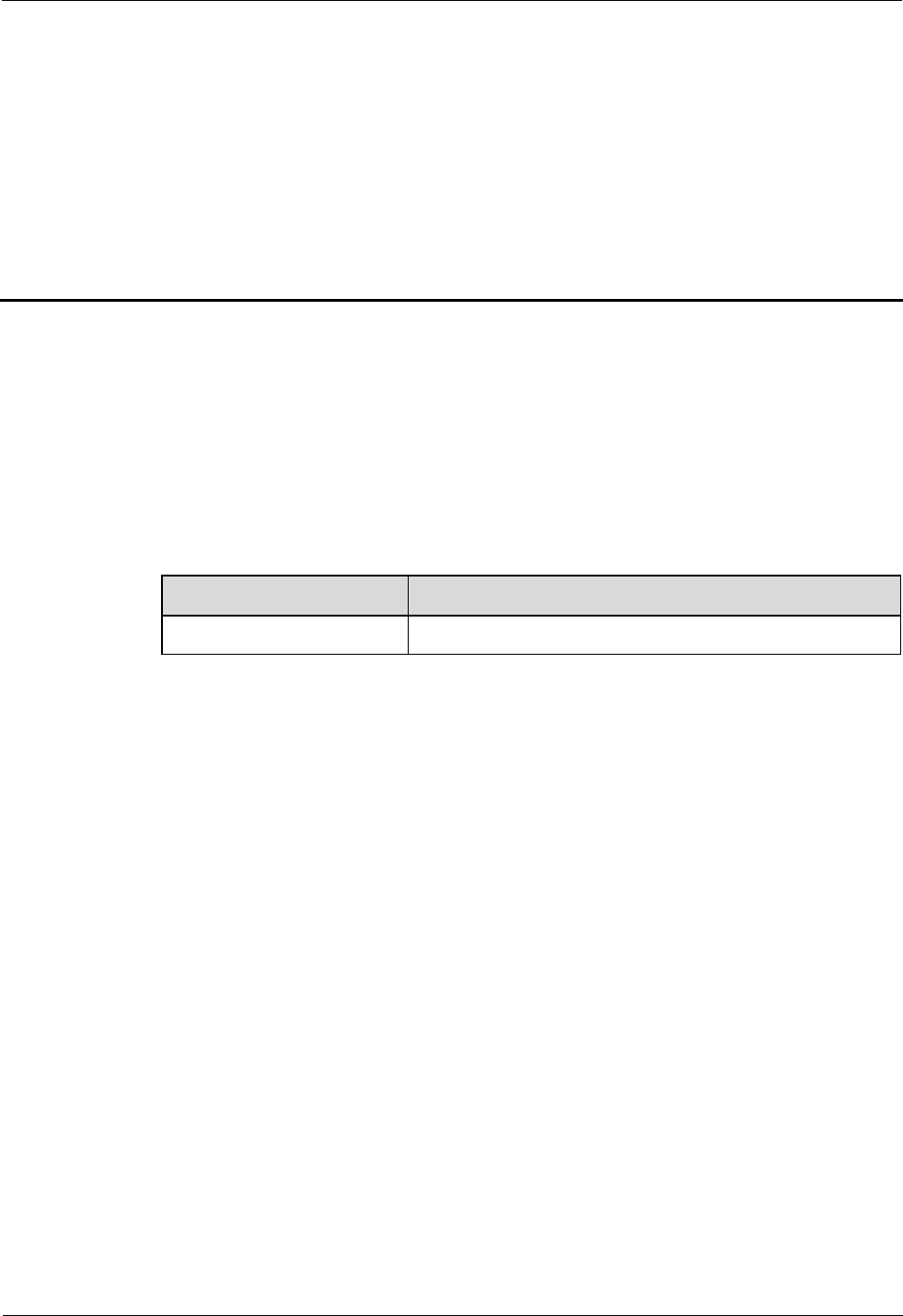
BTS3911E
Site Maintenance Guide
1 BTS3911E Site Maintenance Guide
Issue Draft A (2015-07-30)
Huawei Proprietary and Confidential
Copyright © Huawei Technologies Co., Ltd.
1
1 BTS3911E Site Maintenance Guide
Introduction
This document describes routine maintenance items for a BTS3911E, such as power-on and
power-off operations. It also explains how to replace the components and modules.
Product Version
The following table lists the product version to which this document applies.
Product Name
Product Version
BTS3911E
V100R011C00 and later versions
Intended Audience
This document is intended for:
System engineers
Site maintenance engineers
Organization
1.1 Changes in BTS3911E Site Maintenance Guide
This section describes the changes in BTS3911E Site Maintenance Guide.
1.2 Turning On or Off Indicators
Indicators on the BTS3911E can be turned on or off.
1.3 Powering On or Off a BTS3911E
The indicator status of a BTS3911E must be observed following a power-on to determine its
running status. Normal power-off can be used to power off a BTS3911E.
1.4 Replacing a BTS3911E
BTS3911Es employ modular design and faulty ones must be replaced promptly. Replacing a
BTS3911E interrupts all ongoing services carried by it.

BTS3911E
Site Maintenance Guide
1 BTS3911E Site Maintenance Guide
Issue Draft A (2015-07-30)
Huawei Proprietary and Confidential
Copyright © Huawei Technologies Co., Ltd.
2
1.5 Replacing an Optical Module
An optical module implements photoelectric conversion, enabling optical transmission
between a BTS3911E and other devices. Before replacing an optical module, disconnect the
fiber optic cable from the optical module. The disconnection interrupts transmission of optical
signals.
1.1 Changes in BTS3911E Site Maintenance Guide
This section describes the changes in BTS3911E Site Maintenance Guide.
Draft A (2015-07-30)
This is a draft.
1.2 Turning On or Off Indicators
Indicators on the BTS3911E can be turned on or off.
1.2.1 Turning On Indicators
Indicators on a BTS3911E may need to be turned on before routine maintenance is performed.
Procedure
Instruct the network operator to run the SET INDICATORSW command on the BTS3911E
to turn on the indicators.
Configuration example: SET INDICATORSW: INDICATORSWITCH=ON;
The installation or maintenance personnel can locally observe the indicator status.
1.2.2 Turning Off Indicators
After installation or maintenance is completed, indicators on a BTS3911E can be turned off as
required.
Procedure
Instruct the network operator to run the SET INDICATORSW command on the BTS3911E
to turn off the indicators.
Configuration example: SET INDICATORSW: INDICATORSWITCH=OFF;
The installation or maintenance personnel can locally observe that all the indicators except the
WIFI indicator are off.
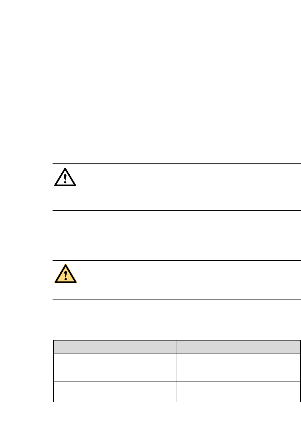
BTS3911E
Site Maintenance Guide
1 BTS3911E Site Maintenance Guide
Issue Draft A (2015-07-30)
Huawei Proprietary and Confidential
Copyright © Huawei Technologies Co., Ltd.
3
1.3 Powering On or Off a BTS3911E
The indicator status of a BTS3911E must be observed following a power-on to determine its
running status. Normal power-off can be used to power off a BTS3911E.
1.3.1 Powering On a BTS3911E
This section describes how to power on a BTS3911E and determine its running status by its
indicator status.
Prerequisites
The BTS3911E and its cables have been installed.
The input voltage of the BTS3911E ranges from 100 V AC to 120 V AC or from 200 V
AC to 240 V AC, and the frequency ranges from 50 Hz to 60 Hz.
Context
CAUTION
After a BTS3911E is unpacked, power it on within 24 hours. If the BTS3911E is powered off
for maintenance, restore power to it within 24 hours.
Procedure
Step 1 Power on the BTS3911E.
DANGER
Do not look into optical modules without eye protection after the BTS3911E is powered on.
Step 2 Wait for 3 to 5 minutes, and observe the indicator status. Then, take actions based on the
indicator status.
Table 1-1 BTS3911E indicator status
If...
Then...
The RUN indicator blinks (on for 1s and off
for 1s), the ALM indicator is off, and the
BTS3911E is running correctly
End the power-on check task.
Any other indicator status is observed
The BTS3911E is faulty. Rectify the faults,
and go to Step 1.
BTS3911E
Site Maintenance Guide
1 BTS3911E Site Maintenance Guide
Issue Draft A (2015-07-30)
Huawei Proprietary and Confidential
Copyright © Huawei Technologies Co., Ltd.
4
Check the status of indicators on all cascaded BTS3911Es in cascading networking.
A BTS3911E takes about 3 minutes to complete the startup procedure, during which the indicator
status is negligible.
During a startup, a BTS3911E reads and writes the flash memory and therefore the indicators
blinking quickly may blink irregularly for 1s to 2s, which does not affect services.
----End
1.3.2 Powering Off a BTS3911E
This section describes how to power off a BTS3911E.
Procedure
Switch off the external power supply equipment for the BTS3911E.
1.4 Replacing a BTS3911E
BTS3911Es employ modular design and faulty ones must be replaced promptly. Replacing a
BTS3911E interrupts all ongoing services carried by it.
Prerequisites
Tools and materials, such as electrostatic discharge (ESD) gloves, torque wrench, and
M10 inner hexagon torque screwdriver, are ready.
The BTS3911E to be replaced has been confirmed, and a new BTS3911E has been
prepared.
You have obtained keys and site visit permission.
Context
CAUTION
Be careful of the overheat on the surface of a BTS3911E that is running or just powered off.
Do not touch it until it cools down.
Procedure
Step 1 Ask the network operator to perform the following preparations for a BTS3911E replacement:
1. Block all the cells served by the BTS3911E to be replaced.
− Run the BLK CELL command if the BTS3911E works in LTE mode.
− Run the BLK ULOCELL command if the BTS3911E works in UMTS mode.
2. Change the SN to that of the new BTS3911E.
BTS3911E
Site Maintenance Guide
1 BTS3911E Site Maintenance Guide
Issue Draft A (2015-07-30)
Huawei Proprietary and Confidential
Copyright © Huawei Technologies Co., Ltd.
5
3. Upload a configuration file for the new BTS3911E over FTP. For details, see BTS3911E
Commissioning Guide.
4. Copy the configuration file and required software package to a TF card or a laptop where
the LMT has been installed.
Switch off the external power supply equipment for the BTS3911E to be replaced.
CAUTION
Do not touch the BTS3911E that is just powered off until it cools down.
Step 2 Put on ESD gloves.
CAUTION
Take proper ESD protection measures, for example, wear ESD gloves, to prevent electrostatic
damage to the BTS3911E or its electronic components.
Step 3 Record the horizontal angle and vertical angle of the BTS3911E. Pay attention to the
direction.
Step 4 Record cable connection positions on the bottom and side maintenance cavities of the
BTS3911E.
Step 5 Disconnect the cables on the BTS3911E bottom and side maintenance cavities from external
devices.
Step 6 Use an M10 inner hexagon torque screwdriver to remove the angle adjusting screw on the top
of the BTS3911E attachment plate. Push the BTS3911E and its attachment plate upward out
of the angle adjusting mounting bracket. See Figure 1-1.
CAUTION
When demounting a BTS3911E, hold the handles tight and gently lift the BTS3911E to
prevent it from falling.
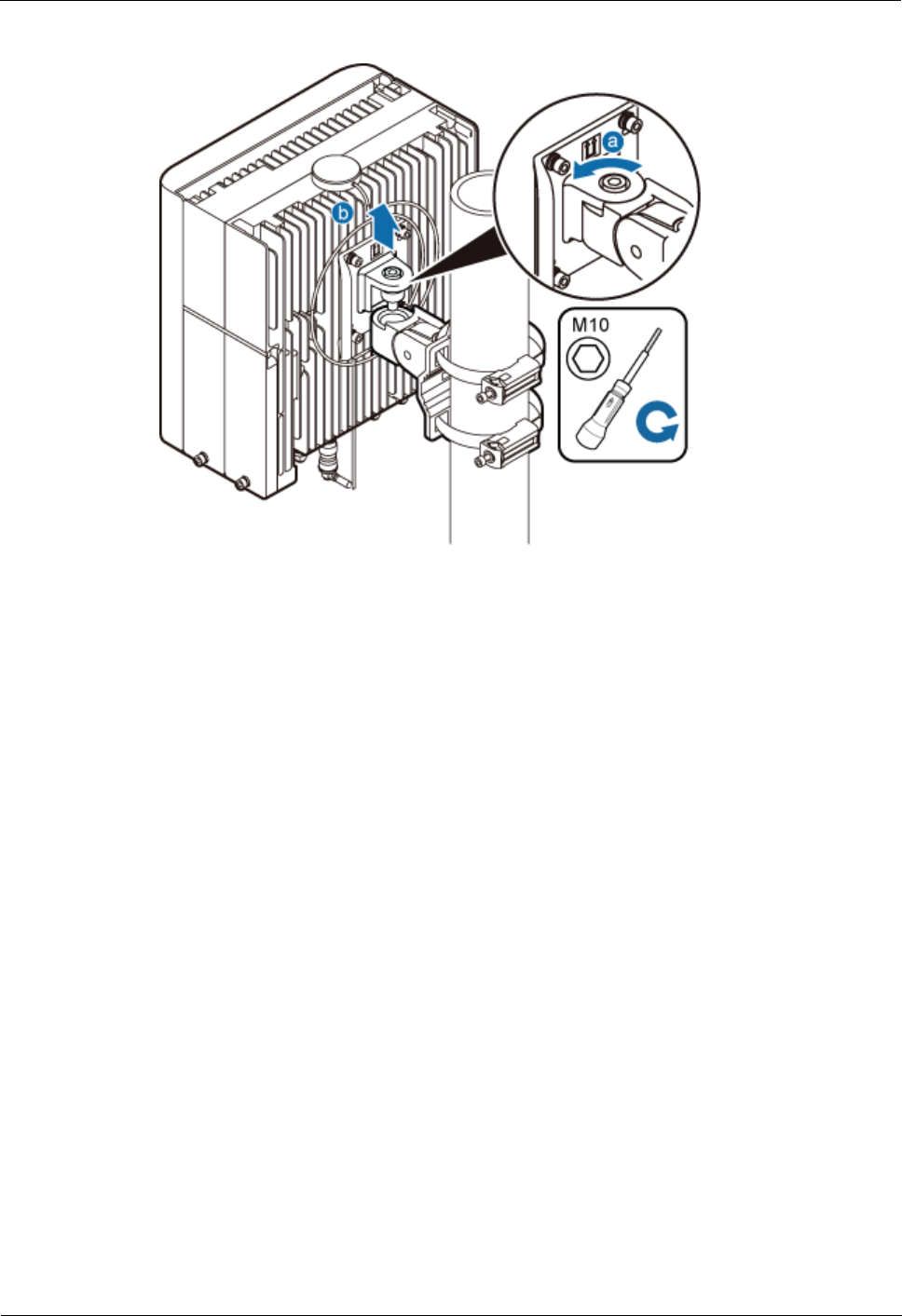
BTS3911E
Site Maintenance Guide
1 BTS3911E Site Maintenance Guide
Issue Draft A (2015-07-30)
Huawei Proprietary and Confidential
Copyright © Huawei Technologies Co., Ltd.
6
Figure 1-1 Demounting a BTS3911E
Step 7 Install a new BTS3911E and adjust the horizontal and vertical angles to be the same as those
recorded in Step 3. Use the M10 inner hexagon torque screwdriver to torque the angle
adjusting screw on the top to 7 N·m.
Step 8 Connect all the cables on the new BTS3911E and seal the vacant ports with waterproof rubber
plugs.
Step 9 Power on the new BTS3911E by following instructions provided in 1.3.1 "Powering On a
BTS3911E."
Step 10 Check the operating status of the new BTS3911E by its indicator status. For the meanings of
the indicator status, see section "Ports and Indicators" in BTS3911E Hardware Description.
Step 11 Download the configuration file and software package to the new BTS3911E using either of
the following methods:
Using the LMT
− On the Upgrade Software tab page, select Download Configuration File,
Download Version Software to download the configuration file and software
package. Select Activate Configuration File and Activate Version Software to
activate the configuration file and software package. After the activation is completed,
the BTS3911E automatically restarts and runs the new software. For details, see LMT
User Guide.
− Check that no alarm is generated on the new BTS3911E. For details, see LMT User
Guide.
Using a TF card. For details, see BTS3911E Commissioning Guide.
Step 12 Request the network operator to perform the following operations:
1. Unblock all cells served by the BTS3911E.
− Run the UBL CELL command if the BTS3911E works in LTE mode.

BTS3911E
Site Maintenance Guide
1 BTS3911E Site Maintenance Guide
Issue Draft A (2015-07-30)
Huawei Proprietary and Confidential
Copyright © Huawei Technologies Co., Ltd.
7
− Run the UBL ULOCELL command if the BTS3911E works in UMTS mode.
2. Manually synchronize inventory data.
3. Manually change the BTS3911E status from TESTING to NORMAL.
Step 13 Take off the ESD gloves and pack up all the tools.
----End
Follow-up Procedure
Place the replaced BTS3911E into an ESD bag. Then, place the ESD bag into a
foam-padded carton or the packing box of the new BTS3911E.
Fill in the fault form with the detail information of the replaced BTS3911E.
Contact the local Huawei office to handle the faulty BTS3911E.
1.5 Replacing an Optical Module
An optical module implements photoelectric conversion, enabling optical transmission
between a BTS3911E and other devices. Before replacing an optical module, disconnect the
fiber optic cable from the optical module. The disconnection interrupts transmission of optical
signals.
Prerequisites
The type and number of optical modules to be replaced are confirmed, and new optical
modules are ready.
Tools and materials, such as ESD gloves, M10 Phillips screwdrivers, ESD box or ESD
bag, are ready.
Context
Optical modules are inserted in FE/GE2 and FE/GE3 ports of the BTS3911E.
Optical modules are hot-swappable.
Optical module replacement involves disconnecting the fiber optic cable, removing the
faulty optical module, inserting a new optical module, connecting the fiber optic cable to
the new module, and waiting for the link on the Ethernet optical port to resume. The
whole process takes about 5 minutes.
Procedure
Step 1 Put on ESD gloves.
CAUTION
Take proper ESD protection measures, for example, wear ESD gloves, to prevent electrostatic
damage to the boards, modules, or electronic components.
Step 2 Record the connection positions of the faulty optical module and fiber optic cable.

BTS3911E
Site Maintenance Guide
1 BTS3911E Site Maintenance Guide
Issue Draft A (2015-07-30)
Huawei Proprietary and Confidential
Copyright © Huawei Technologies Co., Ltd.
8
Step 3 Press the bulge on the optical connector and remove the connector from the faulty optical
module.
CAUTION
Do not look into the disconnected fiber optic cable or optical module without eye protection.
Step 4 Lower the puller on the faulty optical module, and then pull the puller until the optical module
is removed from the BTS3911E.
Step 5 According to the label on the faulty optical module, prepare a new one of the same type.
Install the new optical module into the FE/GE optical port on the BTS3911E.
The new optical module must match the rate at the optical FE/GE port.
Step 6 Insert the optical connector into the optical module.
Step 7 Check the transmission of FE/GE signals by the indicator status. For the meanings of the
indicator status, see section "Ports and Indicators" in BTS3911E Hardware Description.
Step 8 Take off the ESD gloves and pack up all the tools.
----End
Follow-up Procedure
Place the replaced optical module into the ESD box or bag. Then, place the ESD box or
bag into a foam-padded carton or the packing box of the new optical module.
Fill in the fault form with the detail information of the replaced optical module.
Contact the local Huawei office to handle the faulty optical module.

BTS3911E
V100R011C00
Technical Description
Issue Draft A
Date 2015-07-30
HUAWEI TECHNOLOGIES CO., LTD.

Copyright © Huawei Technologies Co., Ltd. 2015. All rights reserved.
No part of this document may be reproduced or transmitted in any form or by any means without prior written
consent of Huawei Technologies Co., Ltd.
Trademarks and Permissions
and other Huawei trademarks are trademarks of Huawei Technologies Co., Ltd.
All other trademarks and trade names mentioned in this document are the property of their respective holders.
Notice
The purchased products, services and features are stipulated by the contract made between Huawei and the
customer. All or part of the products, services and features described in this document may not be within the
purchase scope or the usage scope. Unless otherwise specified in the contract, all statements, information,
and recommendations in this document are provided "AS IS" without warranties, guarantees or representations
of any kind, either express or implied.
The information in this document is subject to change without notice. Every effort has been made in the
preparation of this document to ensure accuracy of the contents, but all statements, information, and
recommendations in this document do not constitute a warranty of any kind, express or implied.
Huawei Technologies Co., Ltd.
Address: Huawei Industrial Base
Bantian, Longgang
Shenzhen 518129
People's Republic of China
Website: http://www.huawei.com
Email: support@huawei.com
Issue Draft A (2015-07-30) Huawei Proprietary and Confidential
Copyright © Huawei Technologies Co., Ltd.
i

Contents
1 BTS3911E Technical Description................................................................................................1
1.1 Changes in BTS3911E Technical Description...............................................................................................................3
1.2 Network Architecture.....................................................................................................................................................3
1.2.1 BTS Node at the RAN Physical Layer........................................................................................................................3
1.2.2 Base Station at the RAN Logical Layer......................................................................................................................4
1.2.3 Mapping of a Base Station at the RAN Physical Layer and RAN Logical Layer.......................................................6
1.3 Logical Structure............................................................................................................................................................6
1.3.1 Subsystems..................................................................................................................................................................6
1.3.2 Functional Structure....................................................................................................................................................7
1.3.3 Resource Model...........................................................................................................................................................8
1.4 Transport Network Topology.........................................................................................................................................9
1.5 Operation and Maintenance..........................................................................................................................................12
1.5.1 O&M Modes..............................................................................................................................................................12
1.5.2 O&M Functions.........................................................................................................................................................13
1.6 Technical Specifications...............................................................................................................................................15
1.7 Typical Power Configuration for BTS3911E...............................................................................................................24
1.8 Reliability.....................................................................................................................................................................27
BTS3911E
Technical Description Contents
Issue Draft A (2015-07-30) Huawei Proprietary and Confidential
Copyright © Huawei Technologies Co., Ltd.
ii

1 BTS3911E Technical Description
Overview
The BTS3911E is a customer-oriented multimode integrated micro base station. This document
describes the BTS3911E in terms of network structure, logical structure, transport network
topologies, operation and maintenance, technical specifications, and reliability. This document
aims to help user better understand the BTS3911E.
Product Version
The following table lists the product version to which this document applies.
Product Name Solution Version Product Version
BTS3911E lSRAN11.0
leRAN11.0
lRAN18.0
V100R011C00
Intended Audience
This document is intended for:
lNetwork planning engineers
lField engineers
lSystem engineers
Organization
1.1 Changes in BTS3911E Technical Description
This chapter describes the changes in BTS3911E Technical Description.
1.2 Network Architecture
The radio access network (RAN) is classified into the RAN physical layer and RAN logical
layer.
1.3 Logical Structure
BTS3911E
Technical Description 1 BTS3911E Technical Description
Issue Draft A (2015-07-30) Huawei Proprietary and Confidential
Copyright © Huawei Technologies Co., Ltd.
1

This section describes the logical structure of a base station in terms of subsystems and functional
structures.
1.4 Transport Network Topology
The BTS3911Es support the star and chain topologies on IP networks.
1.5 Operation and Maintenance
The BTS3911E O&M system manages, monitors, and maintains the BTS3911E software,
hardware, and configuration.
1.6 Technical Specifications
This chapter provides BTS3911E technical specifications, including frequency bands, RF
specifications, capacity specifications, signaling specifications, output power and power
consumption, transmission port specifications, equipment specifications, environment
specifications, and standards compliance.
1.7 Typical Power Configuration for BTS3911E
The BTS3911E can work in UMTS only, LTE FDD only, or UMTS+LTE mode.
1.8 Reliability
This chapter describes the reliability of the BTS3911E, including system reliability, hardware
reliability and software reliability.
BTS3911E
Technical Description 1 BTS3911E Technical Description
Issue Draft A (2015-07-30) Huawei Proprietary and Confidential
Copyright © Huawei Technologies Co., Ltd.
2
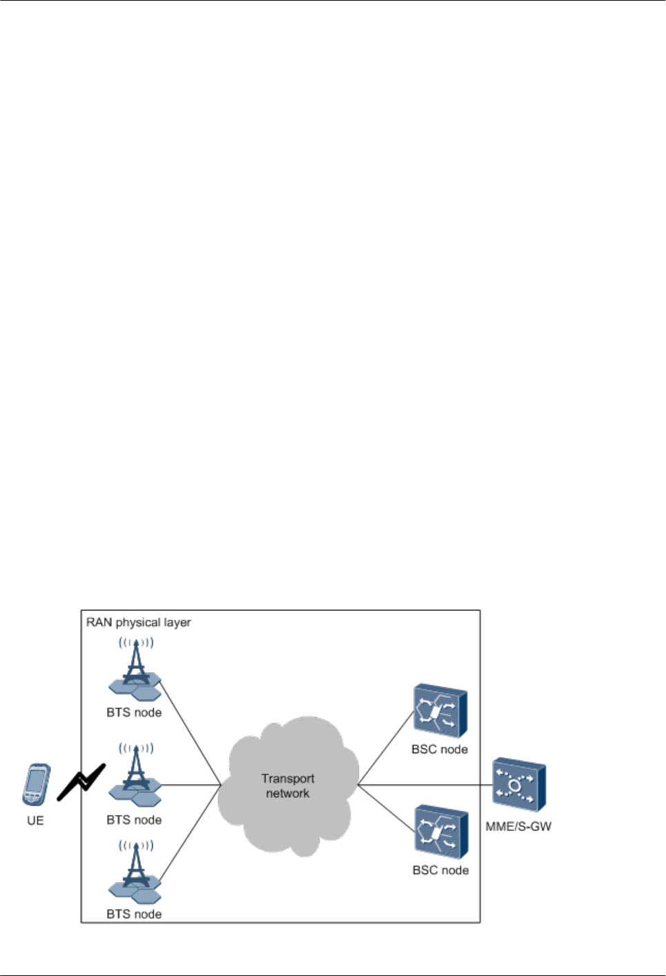
1.1 Changes in BTS3911E Technical Description
This chapter describes the changes in BTS3911E Technical Description.
Draft A (2015-07-30)
This is a draft A.
1.2 Network Architecture
The radio access network (RAN) is classified into the RAN physical layer and RAN logical
layer.
lThe RAN physical layer comprises the physical devices of base stations and base station
controllers. The physical devices interwork with each other over transport networks.
lThe RAN logical layer comprises logical functions implemented on base stations and those
on base station controllers. The logical functions interwork with each other over interface
protocols.
1.2.1 BTS Node at the RAN Physical Layer
The RAN physical layer consists of physical base stations (BTS nodes), physical base station
controllers (BSC nodes), and the transport network that connects the BTS and BSC nodes.
Figure 1-1 shows the position of BTS nodes at the RAN physical layer.
Figure 1-1 BTS nodes at the RAN physical layer
BTS3911E
Technical Description 1 BTS3911E Technical Description
Issue Draft A (2015-07-30) Huawei Proprietary and Confidential
Copyright © Huawei Technologies Co., Ltd.
3
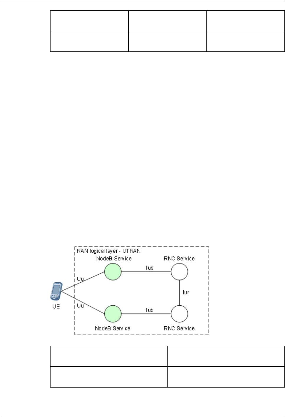
UE: user equipment BTS node: a physical base
station
BSC node: a physical base
station controller
MME: mobility management
entity
S-GW: serving gateway -
lBTS node: Provides the infrastructure and application platform for a base station to
implement NodeB Service and eNodeB Service.
lBSC node: Provides RNC Service.
lTransport network: Forwards data between a BTS node and a BSC node and between a
BTS nodes and the operation and maintenance center (OMC). Multiple modes can use the
same transport network or separate transport networks. The BTS3911Es support IP
transmission.
1.2.2 Base Station at the RAN Logical Layer
The RAN logical layer is classified into the UTRAN and E-UTRAN. It comprisesNodeB
Service, eNodeB Service, and RNC Service. Services interwork with each other over interface
protocols. NodeB Service and eNodeB Service implement the logical functions of base stations,
and RNC Service implements the logical function of base station controllers.
NodeB Service at the UTRAN Logical Layer
The UTRAN logical layer comprises NodeB Service and RNC Service. Figure 1-2 shows the
position of NodeB Service at the UTRAN logical layer.
Figure 1-2 NodeB Service at the UTRAN logical layer
UE: user equipment NodeB Service: services provided by
WCDMA base stations
RNC Service: services provided by WCDMA
base station controllers
UTRAN: universal terrestrial radio access
network
BTS3911E
Technical Description 1 BTS3911E Technical Description
Issue Draft A (2015-07-30) Huawei Proprietary and Confidential
Copyright © Huawei Technologies Co., Ltd.
4
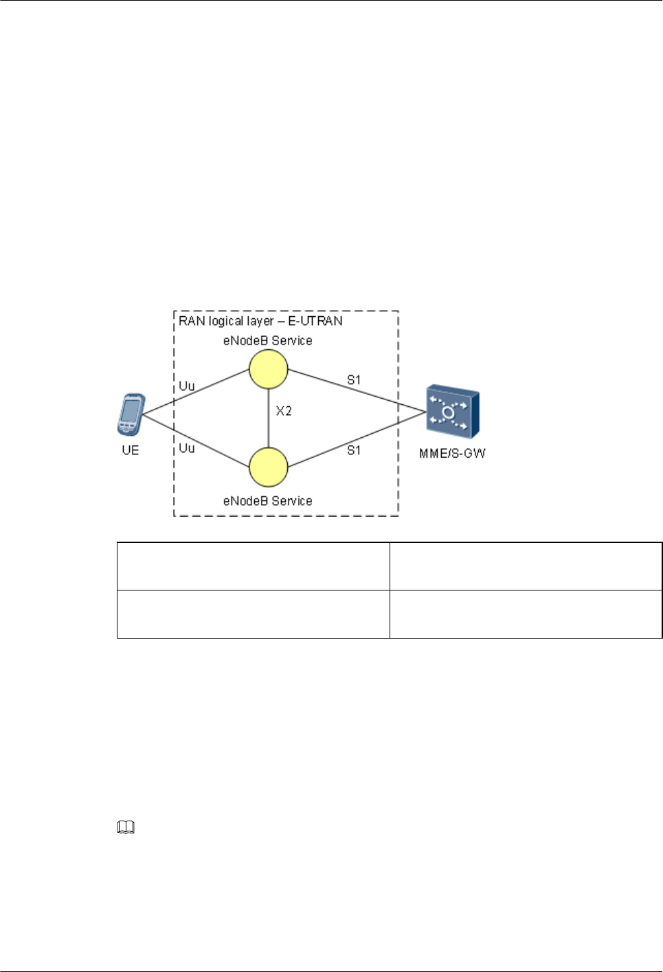
lNodeB Service: Provides logical functions of WCDMA base stations and is controlled by
RNC Service. These functions include radio channel management, physical layer protocol
processing, and signaling procedure processing. NodeB Service interworks with RNC
Service over the Iub interface and interworks with UEs over the Uu interface.
lRNC Service: Provides logical functions of WCDMA base station controllers. These
functions include radio resource management, base station management, mobility
management, and access control. RNC Service interworks with each other over the Iur
interface.
eNodeB Service at the E-UTRAN Logical Layer
The E-UTRAN logical layer provides eNodeB Service. Figure 1-3 shows the position of
eNodeB Service at the E-UTRAN logical layer.
Figure 1-3 eNodeB Service at the E-UTRAN logical layer
UE: user equipment eNodeB Service: services provided by LTE
base stations
MME/S-GW: mobility management entity
and serving gateway
E-UTRAN: evolved universal terrestrial
radio access network
eNodeB Service provides logical functions of LTE base stations. These functions include radio
resource management, radio channel management, mobility management, physical layer
protocol processing, signaling procedure processing, and access control. The LTE FDD single-
mode, LTE TDD single-mode, and LTE FDD/LTE TDD dual-mode configurations are
supported. eNodeB Service interworks with the MME or S-GW over the S1 interface, with other
eNodeB Service over the X2 interface, and with UEs over the Uu interface.
NOTE
The BTS3911Es support LTE FDD but not LTE TDD.
BTS3911E
Technical Description 1 BTS3911E Technical Description
Issue Draft A (2015-07-30) Huawei Proprietary and Confidential
Copyright © Huawei Technologies Co., Ltd.
5

1.2.3 Mapping of a Base Station at the RAN Physical Layer and RAN
Logical Layer
The logical functions of a base station are provided by its physical devices. One physical device
can be configured with one or several logical functions. One BTS node can provide NodeB
Service and eNodeB Service separately or simultaneously.
1.3 Logical Structure
This section describes the logical structure of a base station in terms of subsystems and functional
structures.
1.3.1 Subsystems
The base station subsystems include a control subsystem, transport subsystem, baseband
subsystem, radio frequency (RF) subsystem, clock subsystem, and power and environment
monitoring subsystem.
Figure 1-4 shows the base station subsystems.
Figure 1-4 Base station subsystems
CTL subsystem: control
subsystem
TRP subsystem: transport
subsystem
BB subsystem: baseband
subsystem
BTS3911E
Technical Description 1 BTS3911E Technical Description
Issue Draft A (2015-07-30) Huawei Proprietary and Confidential
Copyright © Huawei Technologies Co., Ltd.
6
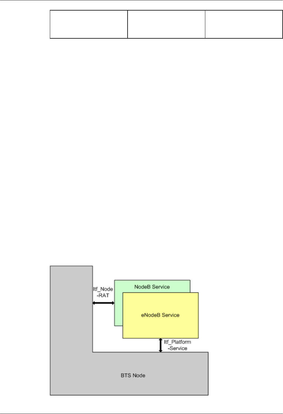
RF subsystem: radio
frequency subsystem
TAS subsystem: clock
subsystem
MPE subsystem: power and
environment monitoring
subsystem
lControl subsystem: Controls and manages resources in a base station. This subsystem
provides the management-plane interface toward the OMC, the control-plane interface
toward other NEs, and the interface for controlling and negotiating common devices in a
multimode base station.
lTransmission subsystem: Forwards data between a base station and a transport network.
This subsystem provides physical ports toward a transport network and the user-plane
interface toward other NEs.
lBaseband subsystem: Processes uplink and downlink baseband data.
lBTS RF subsystem: Receives and transmits radio signals. This subsystem provides the
interface toward the antenna system.
lClock subsystem: Synchronizes the base station clock with external reference clocks. This
subsystem provides the ports toward external reference clocks. For details about multimode
clock sharing, see Common Clock.
lPower and environment monitoring subsystem: Provides power supply and monitors the
environment for a base station. This subsystem provides the ports toward site devices.
1.3.2 Functional Structure
The functional structure of a base station consists of the BTS node, NodeB Service, and eNodeB
Service.
Figure 1-5 shows the functional structure of a base station.
Figure 1-5 Functional structure
BTS3911E
Technical Description 1 BTS3911E Technical Description
Issue Draft A (2015-07-30) Huawei Proprietary and Confidential
Copyright © Huawei Technologies Co., Ltd.
7
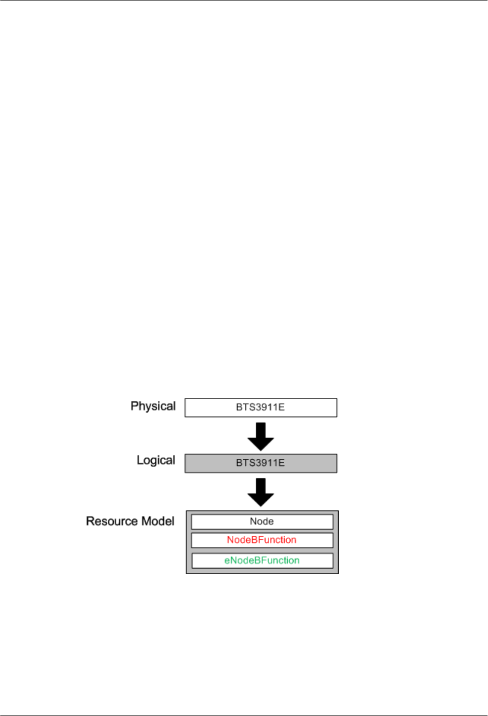
lBTS nodes use abstract resources and a unified interface design to mask software and
hardware differences. Therefore, each Service can be flexibly deployed on each type of
resources. As a result, resources can be flexibly shared and allocated among each type of
Service.
For details about the function of a BTS node, see section 1.2.1 BTS Node at the RAN
Physical Layer"1.2.1 BTS Node at the RAN Physical Layer."
lFor details about the function of NodeB Service and eNodeB Service, see section 1.2.2
Base Station at the RAN Logical Layer"1.2.2 Base Station at the RAN Logical
Layer."
lItf_Platform-Service includes the Service control interfaces provided by a BTS node, such
as the Service deployment interface, version upgrade interface, start and restart interface,
and status monitoring interface.
lItf_Node-RAT includes the interfaces provided by a BTS node to control the common
resources in a base station, such as the resource request, release, activation, and
reconfiguration interfaces. Common resources in a base station include transmission
resources, carrier resource, and universal resources such as SCTP links, TX and RX
channels, and CPU progress.
1.3.3 Resource Model
Function modules of a base station consist of resource modules, including Node,
NodeBFunction, and eNodeBFunction. In charge of device and transmission resources, Node
implements logical functions of a BTS node. In charge of RAT-specific radio resources,
NodeBFunction and eNodeBFunction implement logical functions of NodeB Service and
eNodeB Service, respectively.
Figure 1-6 Mapping between a BTS3911E and its resource model
The resource model of a BTS3911E comprises Node and Function of the specific RAT. The
resource model is managed on the basis of managed objects (MOs), which are defined by
parameters. The MOs and parameters of device and transmission data belong to Node, and those
of radio data belong to Function.
BTS3911E
Technical Description 1 BTS3911E Technical Description
Issue Draft A (2015-07-30) Huawei Proprietary and Confidential
Copyright © Huawei Technologies Co., Ltd.
8
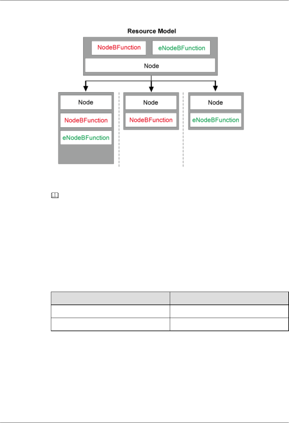
Figure 1-7 Resource model
NOTE
For details about the resource model, MOs, and parameters of the BTS3911E, see BTS3911E Parameter
Reference.
1.4 Transport Network Topology
The BTS3911Es support the star and chain topologies on IP networks.
Table 1-1 describes transmission ports on the BTS3911E.
Table 1-1 Transmission ports
Silkscreen Description
ETH FE/GE electrical port
OPT FE/GE optical port
Star Topology
The star topology is the most commonly used and applies to densely populated areas. Figure
1-8
BTS3911E
Technical Description 1 BTS3911E Technical Description
Issue Draft A (2015-07-30) Huawei Proprietary and Confidential
Copyright © Huawei Technologies Co., Ltd.
9
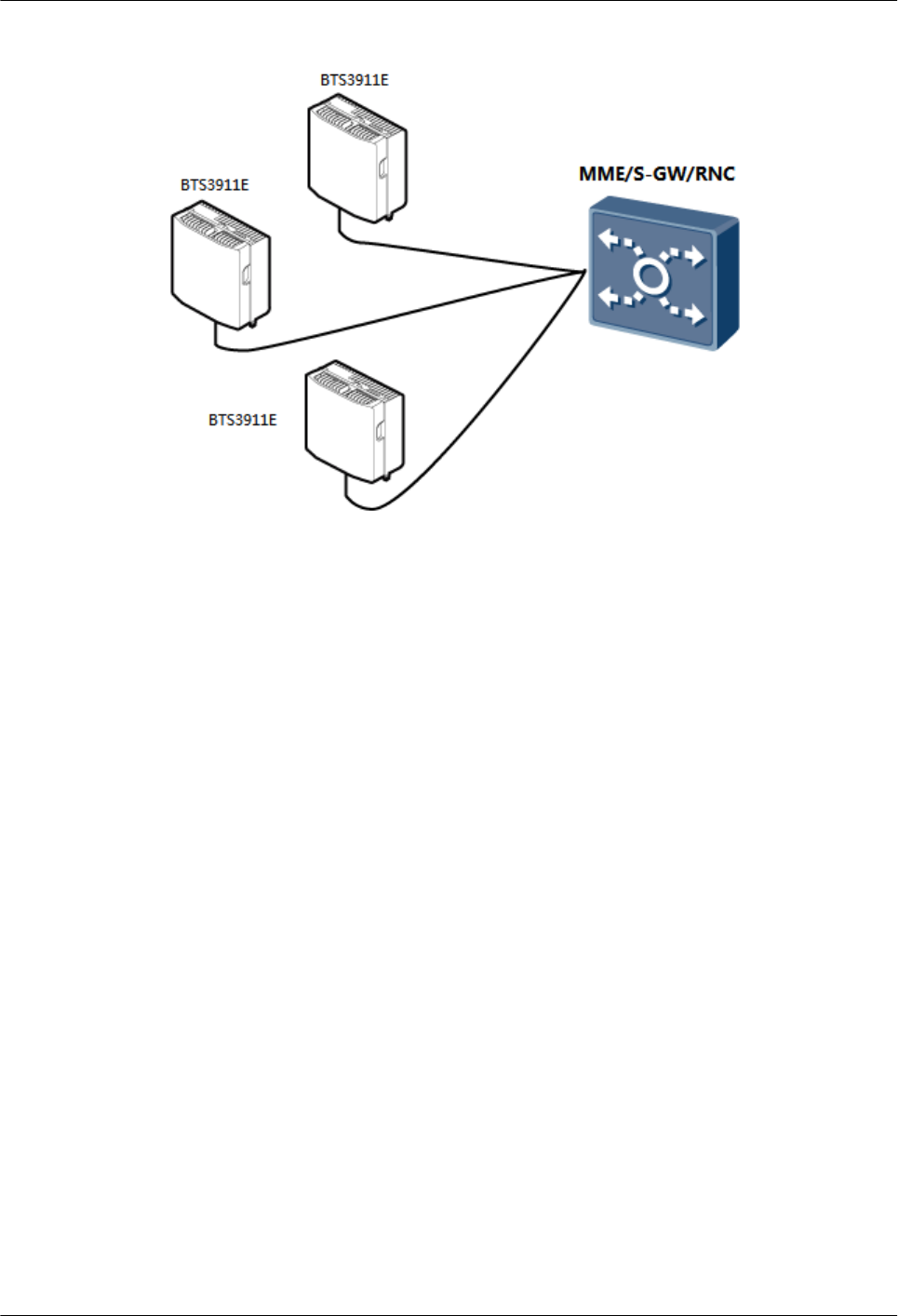
Figure 1-8 Star topology
lAdvantages
–Easy engineering, maintenance, and capacity expansion because each BTS3911E
directly interconnects with an MME, S-GW, or RNC over a transport network
lHigh network reliability because each BTS3911E directly exchanges data with an MME,
S-GW, or RNC.
lDisadvantage: The star topology requires more transmission resources than the chain
topology.
Chain Topology
The chain topology applies to belt-shaped and sparsely populated areas, such as areas along
highways and railways. Figure 1-9
BTS3911E
Technical Description 1 BTS3911E Technical Description
Issue Draft A (2015-07-30) Huawei Proprietary and Confidential
Copyright © Huawei Technologies Co., Ltd.
10
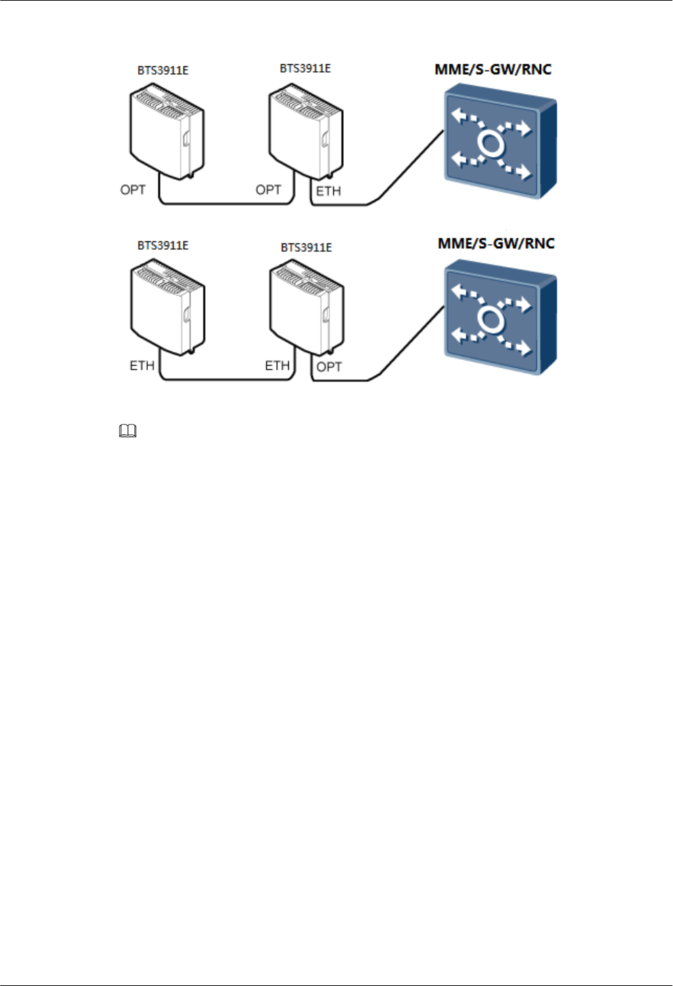
Figure 1-9 Chain topology
NOTE
lThe BTS3911Es do not support the chain topology if the transport network adopts PPPoE
authentication.
lA maximum of three levels of BTS3911Es can be cascaded, that is, three BTS3911Es can be cascaded
in chain topology for transmission resource sharing.
lA BTS3911E can connect to the transport network over an electrical port or optical port, depending
on actual requirements. However, one BTS3911E can use two transmission ports at most, one for
connection to the transport network, and the other for cascading.
lAdvantage: This topology helps reduce the costs for transmission equipment, construction,
and transmission link lease.
lDisadvantages:
–Signals travel through many nodes, lowering network reliability.
–Each lower-level BTS3911E occupies some transmission bandwidth of its upper-level
BTS3911E. Reliability of the upper-level BTS3911E affects operation of the lower-
level BTS3911E.
Chain Topology
The chain topology applies to belt-shaped and sparsely populated areas, such as areas along
highways and railways. Figure 1-10
BTS3911E
Technical Description 1 BTS3911E Technical Description
Issue Draft A (2015-07-30) Huawei Proprietary and Confidential
Copyright © Huawei Technologies Co., Ltd.
11
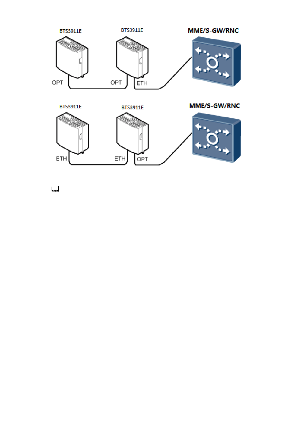
Figure 1-10 Chain topology
NOTE
lThe BTS3911Es do not support the chain topology if the transport network adopts PPPoE
authentication.
lA maximum of three levels of BTS3911Es can be cascaded, that is, three BTS3911Es can be cascaded
in chain topology for transmission resource sharing.
lA BTS3911E can connect to the transport network over an electrical port or optical port, depending
on actual requirements. However, one BTS3911E can use two transmission ports at most, one for
connection to the transport network, and the other for cascading.
lAdvantage: This topology helps reduce the costs for transmission equipment, construction,
and transmission link lease.
lDisadvantages:
–Signals travel through many nodes, lowering network reliability.
–Each lower-level BTS3911E occupies some transmission bandwidth of its upper-level
BTS3911E. Reliability of the upper-level BTS3911E affects operation of the lower-
level BTS3911E.
1.5 Operation and Maintenance
The BTS3911E O&M system manages, monitors, and maintains the BTS3911E software,
hardware, and configuration.
1.5.1 O&M Modes
The BTS3911Es support both local and remote operation and maintenance (O&M).
lLocal maintenance: Maintains a single BTS3911E on the LMT
BTS3911E
Technical Description 1 BTS3911E Technical Description
Issue Draft A (2015-07-30) Huawei Proprietary and Confidential
Copyright © Huawei Technologies Co., Ltd.
12
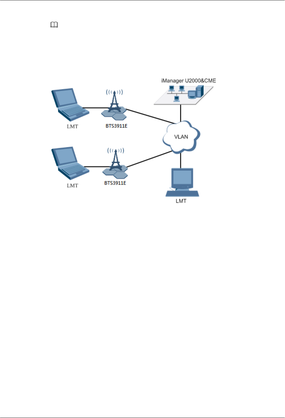
lRemote maintenance: Maintain multiple BTS3911Es on the U2000 or LMT at the OMC
NOTE
U2000 is short for iManager U2000 Mobile Element Management System.
Figure 1-11 shows the BTS3911E O&M system.
Figure 1-11 BTS3911E O&M system
The BTS3911E O&M system includes the following elements:
lLMT: Maintains a single BTS3911E locally or remotely.
lU2000: Maintains multiple BTS3911Es remotely.
lCME: Configures and manages BTS3911E data.
lBTS3911E: Refers to the O&M object.
1.5.2 O&M Functions
The BTS3911E O&M system provides configuration management, fault management,
performance management, security management, software management, deployment
management, device management, and inventory management.
Configuration Management
Configuration management includes data configuration, query, export, backup, and restoration,
as well as configuration synchronization with the U2000.
The data configuration is based on the MOs of the following categories: device, transport, and
service. These categories are independent of each other. In most cases, service data
reconfiguration does not require device data reconfiguration, and device data reconfiguration
does not require service data reconfiguration either.
BTS3911E
Technical Description 1 BTS3911E Technical Description
Issue Draft A (2015-07-30) Huawei Proprietary and Confidential
Copyright © Huawei Technologies Co., Ltd.
13

Fault Management
Fault management involves fault detection, fault isolation, self-healing, alarm reporting, and
alarm correlation. The BTS3911E O&M system can manage faults in hardware, environment,
software, transmission, cells, and services.
lFault isolation prevents faults from affecting the BTS3911E operational continuity. Self-
healing minimizes the impact of faults on services by lowering specifications or
reestablishing cells.
lAlarm correlation enables a BTS3911E to report only the root fault and the ultimate impact
on services.
Performance Management
Performance management involves periodic performance measurement on the BTS3911Es and
the collection, storage, and reporting of measurement results.
The BTS3911Es collect performance statistics every 5, 15, 30, or 60 minutes and can store the
results in a maximum of three days. The performance measurement covers the BTS3911E, cell,
neighboring cell, transmission, standard interface, and device usage measurement.
The BTS3911Es support real-time KPI monitoring at intervals of 1 minute, which helps detect
and diagnose faults in a timely manner.
Tracing Management
Tracing management facilitates routine maintenance, commissioning, and troubleshooting by
tracing internal messages, messages over the interfaces and signaling links, and messages to and
from UEs.
Security Management
Security management implements user authentication and access control, including user account
management, rights management, login management, identity authentication, and operation
authentication.
Transmission channels between the BTS3911Es and the U2000 can run over Secure Socket
Layer (SSL).
Security management provides network- and user-specific security services, including the
following:
lEncryption: Encrypts important user information.
lAuthentication: Manages and authenticates user accounts.
lAccess control: controls user operations.
lSecurity protocol: supports SSL.
Software Management
Software management involves software version management, software version upgrade, and
patch management.
lSoftware version management: Software versions can be queried, backed up, and restored.
BTS3911E
Technical Description 1 BTS3911E Technical Description
Issue Draft A (2015-07-30) Huawei Proprietary and Confidential
Copyright © Huawei Technologies Co., Ltd.
14

lSoftware version upgrade: The BTS3911Es can be remotely upgraded in batches. With the
one-click remote upgrade wizard provided by the U2000, you can:
–Perform health checks before and after upgrades.
–Back up, download, and activate software.
–Check the upgrade status and results.
The BTS3911Es support automatic configuration updates during upgrades. To complete
an upgrade, simply follow the instructions on the upgrade wizard. The BTS3911Es also
support rapid version rollback by using a single command, reducing the impact of upgrade
failures.
lPatch management involves patch query, download, activation, deactivation, rollback, and
removal.
Deployment Management
The BTS3911E deployment solutions include automatic BTS3911E discovery, BTS3911E
deployment by USB, remote BTS3911E deployment, and radio parameter self-planning. These
solutions allow onsite installation personnel to simply install hardware without the need for
portable computers, reducing deployment workload and increasing deployment efficiency.
lAutomatic BTS3911E discovery: Eliminates the need to configure the IP addresses of the
BTS3911Es and the EMS.
lBTS3911E deployment by USB: Downloads software and data stored in a USB flash drive
to the BTS3911Es. This reduces the download duration when the bandwidth of transmission
between the BTS3911Es and the EMS is insufficient.
lRemote BTS3911E deployment: Allows software commissioning and acceptance at the
OMC.
lRadio parameter self-planning: Generates radio parameters for the BTS3911Es in online
mode, lessening the workload of parameter planning and configuration.
Device Management
Device management involves data configuration, status management, fault detection, and
troubleshooting for all the physical BTS3911E devices. On the BTS3911E device panel, you
can easily view the device status and perform simple operations such as query and reset.
Inventory Management
Inventory management involves collection and reporting of the inventory information about
BTS3911Es. Inventory management makes it possible to centrally manage network equipment
assets at the OMC.
1.6 Technical Specifications
This chapter provides BTS3911E technical specifications, including frequency bands, RF
specifications, capacity specifications, signaling specifications, output power and power
consumption, transmission port specifications, equipment specifications, environment
specifications, and standards compliance.
BTS3911E
Technical Description 1 BTS3911E Technical Description
Issue Draft A (2015-07-30) Huawei Proprietary and Confidential
Copyright © Huawei Technologies Co., Ltd.
15

Frequency Band
Table 1-2 Frequency band
Scenario Mode Frequen
cy Band
(MHz)
RX
Frequency
Band (MHz)
TX
Frequency
Band
(MHz)
Support
ed
Bandwi
dth
(MHz)
IBW
(MHz
)
1800 MHz LTE
FDD
1800 1710 to 1785 1805 to 1880 5, 10, 15,
or 20
40
2100 MHz LTE
FDD
2100 1920 to 1980 2110 to 2170 5, 10, 15,
or 20
40
2100 MHz UMTS 2100 1920 to 1980 2110 to 2170 5 40
2100 MHz
LTE FDD
+2100
MHz
UMTS
LTE
FDD
2100 1920 to 1980 2110 to 2170 5, 10, 15,
or 20
40
UMTS 2100 1920 to 1980 2110 to 2170 5 40
1800 MHz
LTE FDD
+2100
MHz LTE
FDD
LTE
FDD
1800 1710 to 1785 1805 to 1880 5, 10, 15,
or 20
40
LTE
FDD
2100 1920 to 1980 2110 to 2170 5, 10, 15,
or 20
40
1800 MHz
LTE FDD
+2100
MHz
UMTS
LTE
FDD
1800 1710 to 1785 1805 to 1880 5, 10, 15,
or 20
40
UMTS 2100 1920 to 1980 2110 to 2170 5 40
1800 MHz
LTE FDD
+2100
MHz LTE
FDD+2100
MHz
UMTS
LTE
FDD
1800 1710 to 1785 1805 to 1880 5, 10, 15,
or 20
40
LTE
FDD
2100 1920 to 1980 2110 to 2170 5, 10, 15,
or 20
40
UMTS 2100 1920 to 1980 2110 to 2170 5 40
RF specifications
Table 1-3 describes the TX/RX channel and receive sensitivity of a BTS3911E.
BTS3911E
Technical Description 1 BTS3911E Technical Description
Issue Draft A (2015-07-30) Huawei Proprietary and Confidential
Copyright © Huawei Technologies Co., Ltd.
16
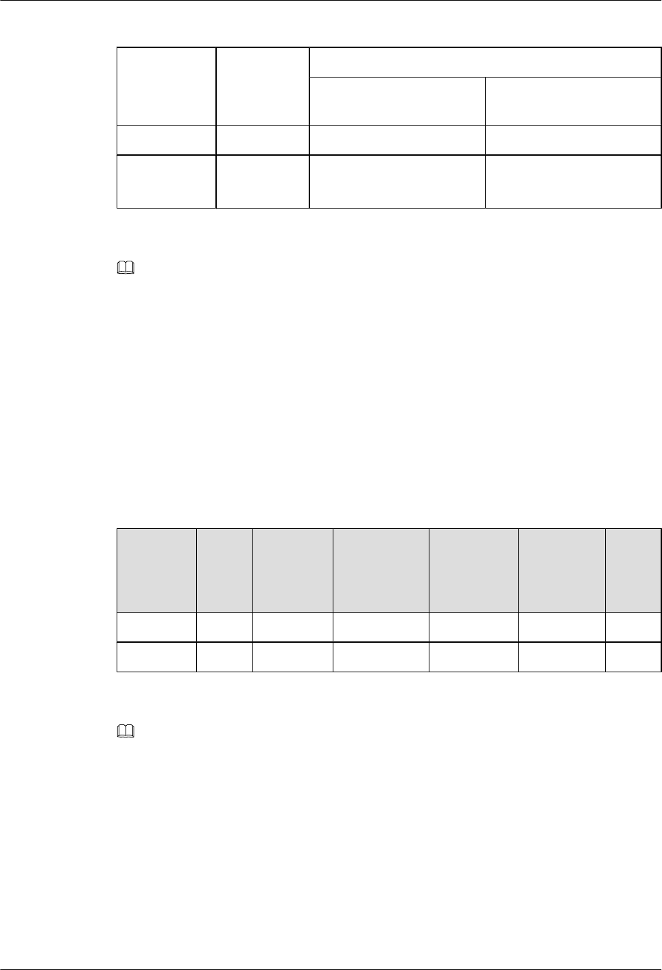
Table 1-3 TX/RX channel and receive sensitivity
Frequency
Band (MHz)
TX/RX
Channel
Receive Sensitivity (dBm)
Single-antenna Receive
Sensitivity (dBm)
Dual-antenna Receive
Sensitivity (dBm)
1800 2T2R LTE: -103 LTE: -105.8
2100 2T2R LTE: -103
UMTS: -123
LTE: -105.8
UMTS: -125.8
NOTE
The receive sensitivity in UMTS mode is measured at the antenna connector under the conditions
recommended in 3GPP TS 25.104:
lThe channel rate is 12.2 kbit/s.
lThe bit error rate does not exceed 0.001.
The receive sensitivity in LTE mode is measured under the conditions recommended in annex A in 3GPP
TS 36.104:
lThe channel bandwidth is 5 MHz.
lThe reference measurement channel is FRC A1-3 in annex A.1 (QPSK, R = 1/3, 25 RBs);
The BTS3911Es support internal and external antennas. Table 1-4 lists the internal antenna
specifications.
Table 1-4 Internal antenna specifications
Frequenc
y Band
(MHz)
Gain
(dBi)
Polarizati
on Mode
Directionali
ty
Vertical
Lobe
Width (3
dB)
Horizontal
Lobe
Width (3
dB)
VSW
R
1800 11 ±45° Directional 65° 32° < 2
2100 11 ±45° Directional 65° 32° < 2
NOTE
The internal antenna of a BTS3911E is not preconfigured with a tilt.
Capacity Specifications
Table 1-5 lists the capacity specifications of a BTS3911E in LTE only mode.
BTS3911E
Technical Description 1 BTS3911E Technical Description
Issue Draft A (2015-07-30) Huawei Proprietary and Confidential
Copyright © Huawei Technologies Co., Ltd.
17
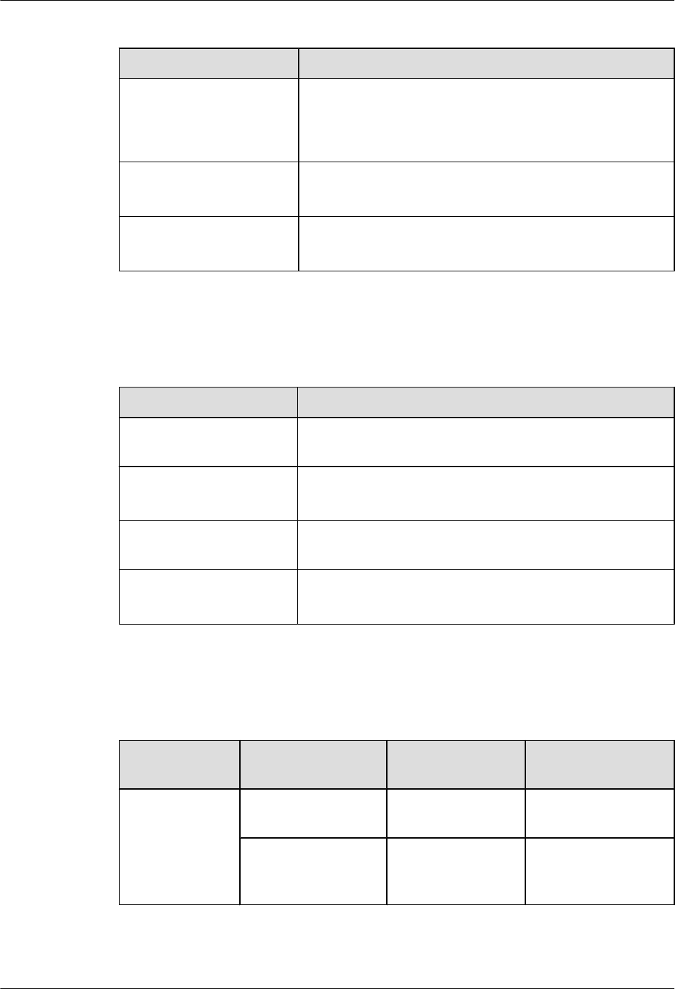
Table 1-5 Capacity specifications in LTE only mode
Item Specifications
Maximum number of cells
per BTS3911E
Three 20 MHz cells
NOTE
A single-band BTS3911E supports a maximum of two 2T2R cells. A
dual-band BTS3911E supports a maximum of three 2T2R cells.
Maximum number of UEs in
RRC_Connected mode
lPer cell: 600
lPer BTS3911E: 1200
Maximum throughput per
BTS3911E
lDownlink: 450 Mbit/s
lUplink: 225 Mbit/s
Table 1-6 lists the capacity specifications of a BTS3911E in UMTS only mode.
Table 1-6 Capacity specifications in UMTS only mode
Item Specifications
Maximum number of cells
per BTS3911E
Four cells
Maximum number of CEs
per BTS3911E
lDownlink: 512 CEs
lUplink: 512 CEs
Maximum number of UEs
per BTS3911E
384 HSPA UEs
Maximum throughput per
BTS3911E
lDownlink: 168 Mbit/s
lUplink: 46 Mbit/s
Table 1-7 lists the capacity specifications of a BTS3911E in UMTS+LTE mode.
Table 1-7 Capacity specifications in UMTS+LTE mode
Recommended
Configuration
Item UMTS
Specifications
LTE Specifications
Four UMTS cells
and one LTE cell
Maximum number of
cells per BTS3911E
Four cells One 20 MHz cell
Maximum number of
UEs per BTS3911E
192 HSPA UEs 600 UEs in
RRC_Connected
mode
BTS3911E
Technical Description 1 BTS3911E Technical Description
Issue Draft A (2015-07-30) Huawei Proprietary and Confidential
Copyright © Huawei Technologies Co., Ltd.
18
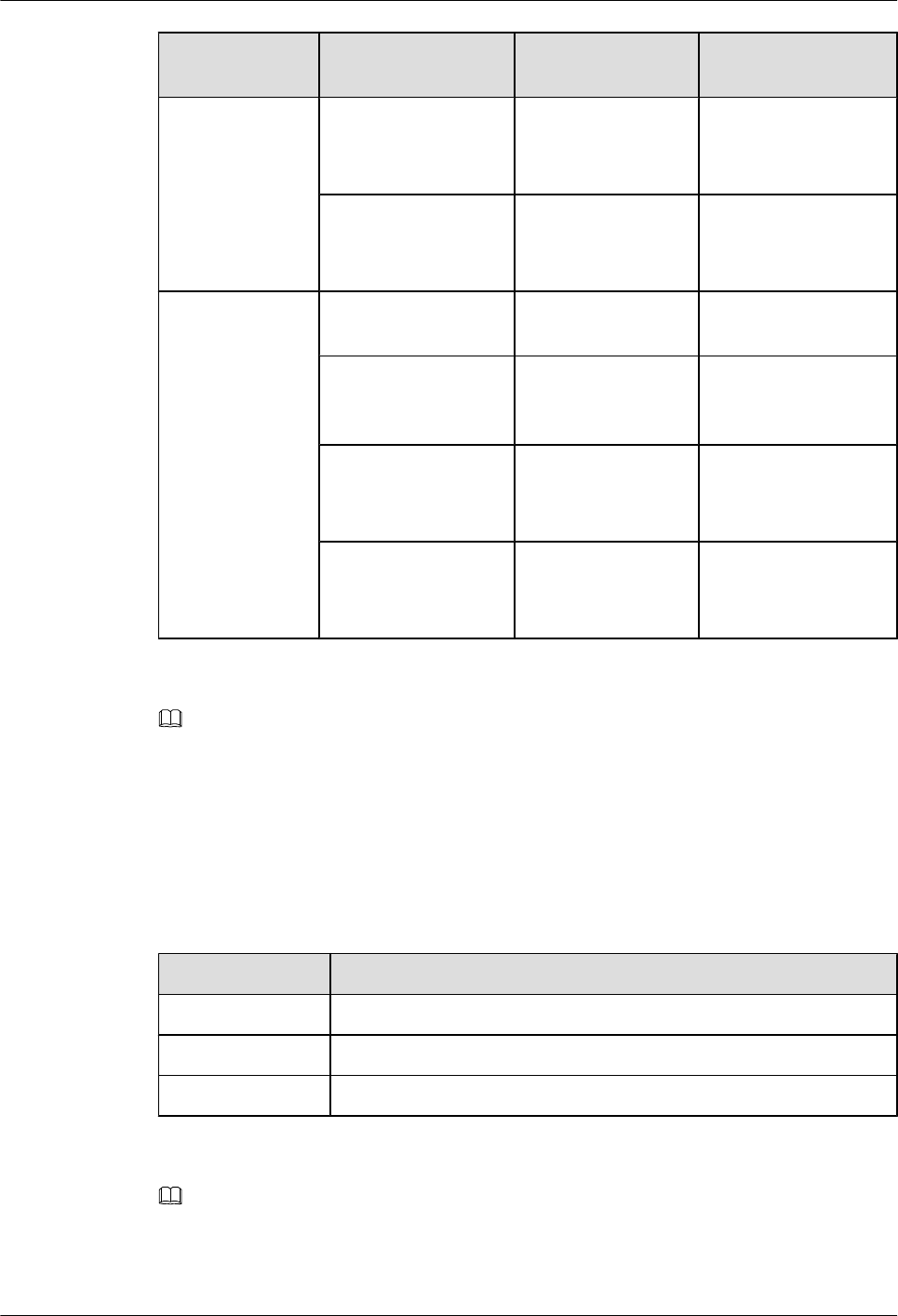
Recommended
Configuration
Item UMTS
Specifications
LTE Specifications
Maximum throughput
per BTS3911E
lDownlink: 168
Mbit/s
lUplink: 46 Mbit/s
lDownlink: 150
Mbit/s
lUplink: 75 Mbit/s
Maximum number of
CEs per BTS3911E
lDownlink: 256
CEs
lUplink: 256 CEs
-
Two UMTS cells
and two LTE cell
Maximum number of
cells per BTS3911E
Two cells Two 20 MHz cells
Maximum number of
UEs per BTS3911E
192 HSPA UEs 600 UEs in
RRC_Connected
mode
Maximum throughput
per BTS3911E
lDownlink: 84
Mbit/s
lUplink: 23 Mbit/s
lDownlink: 300
Mbit/s
lUplink: 150 Mbit/s
Maximum number of
CEs per BTS3911E
lDownlink: 256
CEs
lUplink: 256 CEs
-
NOTE
lA UMTS/LTE FDD dual-mode BTS3911E does not support four UMTS cells and two LTE cells
concurrently.
lA maximum of four UMTS cells, two 2T2R LTE cells, or two UMTS cells+one 2T2R LTE cell can
be configured for a BTS3911E on a single frequency band.
Signaling Specifications
Table 1-8 Signaling specifications
Mode Signaling Specifications
LTE 216000 BHCA
UMTS 100 CNBAPS
UL UMTS 80 CNBAPS + LTE 108000 BHCA
NOTE
Busy hour call attempts (BHCA) indicates the number of calls processed during the busiest hour. The
BHCA represents the signaling processing capability of a system because calls require signaling
transmission.
BTS3911E
Technical Description 1 BTS3911E Technical Description
Issue Draft A (2015-07-30) Huawei Proprietary and Confidential
Copyright © Huawei Technologies Co., Ltd.
19
Output Power and Power Consumption
Table 1-9 Output power and power consumption
Maximum Output Power
(W)
Typical Power
Consumption (W)
Maximum Power
Consumption (W)
2 x 2 x 5
For details about the typical
output power configuration,
see 1.7 Typical Power
Configuration for
BTS3911E.
200 220
NOTE
In the Maximum Output Power (W) column, A x B x C indicates that a BTS3911E provides A frequency
bands with B TX channels per band and C W transmit power per channel.
The preceding output power and consumption excludes the external PoE power supply.
Transmission Port Specifications
Table 1-10 Transmission port specifications
Transmission Port Type Number of Ports
FE/GE electrical port 2
FE/GE optical port 2
NOTE
The BTS3911E supports external PoE power supply over its FE/GE electrical ports, with a maximum
output power of 60 W.
Equipment Specifications
Table 1-11 Clock specifications
Item Synchronization Precision
IEEE 1588v2-based IP clock lFrequency synchronization precision: ±0.05 ppm
lTime synchronization precision: 1.5 us
GPS clock
Synchronous Ethernet clock Frequency synchronization precision: ±0.05 ppm
BTS3911E
Technical Description 1 BTS3911E Technical Description
Issue Draft A (2015-07-30) Huawei Proprietary and Confidential
Copyright © Huawei Technologies Co., Ltd.
20
Table 1-12 Power specifications
Input Power Voltage Range Frequency
110 V AC 100 V AC to 120 V AC 50 Hz/60 Hz
220 V AC 200 V AC to 240 V AC 50 Hz/60 Hz
Table 1-13 Dimensions and weight
Item Specifications
Dimensions (H x W x D) lWith internal antennas: 290 mm x 300 mm x 166 mm
lWithout internal antennas: 290 mm x 300 mm x 118 mm
Weight lWith internal antennas: ≤ 13.6 kg
lWithout internal antennas: ≤ 11.6 kg
Environment Specifications
Table 1-14 Environment specifications
Item Specifications
Operating temperature -40°C to +55°C (with solar radiation)
-40°C to +50°C (without solar radiation)
Storage temperature -40°C to +70°C
Relative humidity 5% RH to 95% RH
Absolute humidity (1 to 30) g/m3
Altitude -60 m to +1800 m
Operating atmospheric
pressure
70 kPa to 106 kPa
Operating environment EUROPEAN ETS 300 019-1-4 Class4.1
Storage environment ETSI EN300019-1-1 class 1.2 "Weather protected, not
temperature-controlled storage locations"
Transportation
environment
ETSI EN300019-1-2 class 2.3 "Public transportation"
Protection rating IP65
BTS3911E
Technical Description 1 BTS3911E Technical Description
Issue Draft A (2015-07-30) Huawei Proprietary and Confidential
Copyright © Huawei Technologies Co., Ltd.
21

Item Specifications
Anti-seismic performance IEC 60068-2-57 Environmental testing – Part 2-57: Tests – Test
Ff: Vibration – Time-history method
ETSI EN300019-2-4
YD5083-99: Interim Provisions for Test of Anti-seismic
Performances of Telecommunications Equipment
(telecommunications industry standard in People's Republic of
China)
Protection against the
moisture, salt spray, and
fungus
IEC60068-2-30
IEC60068-2-52
IEC60068-2-10
Storage time To avoid product degradation, it is a good practice to put the
BTS3911E into use within the first year of storage.
Standards Compliance
Table 1-15 Standards compliance
Item Specifications
EMC The BTS3911E complies with the following standards related
to electromagnetic compatibility:
lCISPR 22
lEN 55022
lEN 301 489-17
lEN 301 489-23
lCISPR 24
lIEC 61000-4-2
lIEC 61000-4-3
lIEC 61000-4-4
lIEC 61000-4-5
lIEC 61000-4-6
lIEC 61000-4-29
lGB 9254
lETSI 301 489-1
lVCCI V-3
3GPP R99, R4, R5, R6, R7, R8, R9, and R10
Environmental standards RoHS
Surge protection standards IEC61000-4-5, IEC 61312-1, and YD 5098
BTS3911E
Technical Description 1 BTS3911E Technical Description
Issue Draft A (2015-07-30) Huawei Proprietary and Confidential
Copyright © Huawei Technologies Co., Ltd.
22
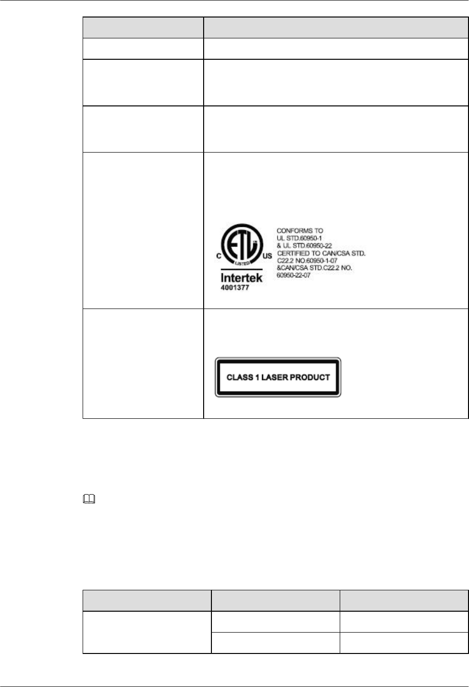
Item Specifications
Protection standards YD 5098, YD 5068-98, and IEC 61000-4-5
Safety standards UL60950-1, IEC60950-1, EN60950-1, AS/NZS60950-1,
UL60950-22, IEC60950-22, EN60950-22, and AS/
NZS60950-22
Environment standards IEC 68-2-1, IEC 68-2-2, IEC60068-2-2, ETSI EN300019-1-1,
ETSI EN300019-1-2, ETSI EN300019-1-4, and ETSI
EN300019-2-4
ETL Conforms to UL STD.60950-1 & UL STD.60950-22
CERTIFIED TO CAN/CSA STD.C22.2 NO.60950-1-07 &
CAN/CSA STD.C22.2 NO.60950-22-07
The follow figure shows the identity of ETL:
Laser safety class CLASS 1 LASER PRODUCT
The follow figure shows the identity of laser safety class:
Port Surge Protection Specifications
Table 6-2 lists the port surge protection specifications of a BTS3911E.
NOTE
Unless otherwise specified, the surge protection specifications are based on the surge waveform of 8/20
μs.
All the surge current items, unless otherwise specified as maximum discharge current, refer to nominal
discharge current.
Table 1-16 Surge protection specifications
Port Surge Protection Mode Specification
AC power socket Differential mode 20 kA
Common mode 20 kA
BTS3911E
Technical Description 1 BTS3911E Technical Description
Issue Draft A (2015-07-30) Huawei Proprietary and Confidential
Copyright © Huawei Technologies Co., Ltd.
23
1.7 Typical Power Configuration for BTS3911E
The BTS3911E can work in UMTS only, LTE FDD only, or UMTS+LTE mode.
Table 1-17 and Table 1-18 describe the typical power configuration for a BTS3911E working
in LTE FDD only mode at the 1800 MHz or 2100 MHz band.
Table 1-19 and Table 1-20 describe the typical power configuration for a BTS3911E working
in UMTS only mode at the 2100 MHz band.
Table 1-21 and Table 1-22 describe the typical power configuration for a BTS3911E working
in UMTS+LTE FDD mode at the 2100 MHz band.
NOTE
lA BTS3911E working in LTE FDD only mode can be configured with a maximum of three carriers:
a maximum of two carriers on one frequency band and the remaining carriers allocated to the other
frequency band
lA BTS3911E working in UMTS only mode can be configured with a maximum of four carriers.
lA BTS3911E working in UMTS+LTE FDD mode can be configured with a maximum of four UMTS
carriers plus one LTE carrier or two UMTS carriers plus two LTE carriers: a maximum of two UMTS
carriers plus one LTE carrier on one frequency band and the remaining carriers allocated to the other
frequency band
Table 1-17 Typical power configuration in LTE FDD only mode at the 1800 MHz or 2100 MHz
band
Mode Number of LTE
FDD Carriers
Output Power per
LTE FDD Carrier
(W)
Supported LTE
FDD Cell
Bandwidth (MHz)
LTE FDD 1 (MIMO) 2x5 5, 10, 15, 20
2 (MIMO) 2x2.5 5, 10, 15, 20
Table 1-18 Typical PA power configuration in LTE FDD only mode at the 1800 MHz or 2100
MHz band
Carrier
Configuration
PA 1 PA 2
Total Number of
LTE FDD
Carriers
Output Power
per LTE FDD
Carrier (W)
Total Number of
LTE FDD
Carriers
Output Power
per LTE FDD
Carrier (W)
One LTE FDD
carrier (MIMO)
1 5 1 5
Two LTE FDD
carriers
(MIMO)
2 2.5 2 2.5
BTS3911E
Technical Description 1 BTS3911E Technical Description
Issue Draft A (2015-07-30) Huawei Proprietary and Confidential
Copyright © Huawei Technologies Co., Ltd.
24
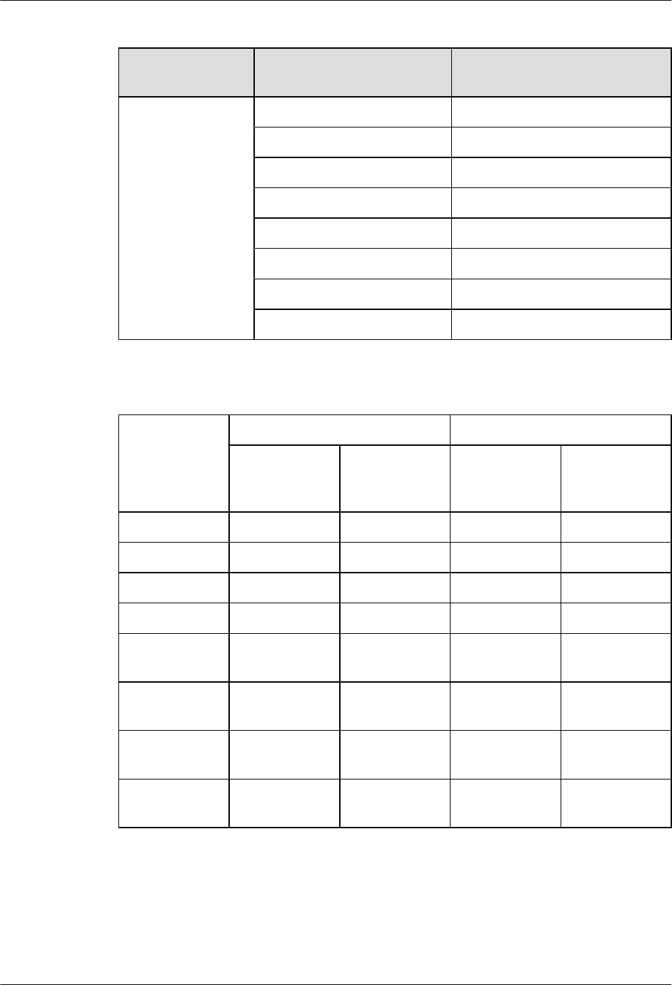
Table 1-19 Typical power configuration in UMTS only mode at the 2100 MHz band
Mode Total Number of UMTS
Carriers
Output Power per UMTS
Carrier (W)
UMTS 1 Configured on one PA: 5
2 Configured on one PA: 2.5
3 Configured on one PA: 1.7
4 Configured on one PA: 1.25
1 (MIMO) 2x5
2 (MIMO) 2x2.5
3 (MIMO) 2x1.7
4 (MIMO) 2x1.25
Table 1-20 Typical PA power configuration in UMTS only mode at the 2100 MHz band
Carrier
Configuration
PA1 PA2
Total Number of
UMTS Carriers
Output Power
per UMTS
Carrier (W)
Total Number of
UMTS Carriers
Output Power
per UMTS
Carrier (W)
One carrier 1 5 0 0
Two carriers 2 2.5 0 0
Three carriers 3 1.7 0 0
Four carriers 4 1.25 0 0
One carrier
(MIMO)
1 5 1 5
Two carriers
(MIMO)
2 2.5 2 2.5
Three carriers
(MIMO)
3 1.7 3 1.7
Four carriers
(MIMO)
4 1.25 4 1.25
BTS3911E
Technical Description 1 BTS3911E Technical Description
Issue Draft A (2015-07-30) Huawei Proprietary and Confidential
Copyright © Huawei Technologies Co., Ltd.
25

Table 1-21 Typical power configuration in UMTS+LTE FDD mode at the 2100 MHz band
Mode Total
Number of
UMTS
Carriers
Total
Number of
LTE FDD
Carriers
Output
Power per
UMTS
Carrier (W)
Output
Power per
LTE FDD
Carrier (W)
Supported
LTE FDD
Bandwidth
UMTS
+LTE FDD
1 1 (MIMO) Configured
on one PA:
2.5
2x2.5 5, 10, 15, 20
UMTS
+LTE FDD
2 1 (MIMO) Configured
on one PA:
1.7
2x1.7 5, 10, 15, 20
UMTS
+LTE FDD
1 (MIMO) 1 (MIMO) 2x2.5 2x2.5 5, 10, 15, 20
UMTS
+LTE FDD
2 (MIMO) 1 (MIMO) 2x1.7 2x1.7 5, 10, 15, 20
Table 1-22 Typical PA power configuration in UMTS+LTE FDD mode at the 2100 MHz band
Carrier Configuration PA1 PA2
Total
Num
ber
of
UM
TS
Carri
ers
Output
Power
per
UMTS
Carrier
(W)
Total
Num
ber
of
LTE
FDD
Carri
ers
Outp
ut
Pow
er
per
LTE
FDD
Carri
er
(W)
Total
Numb
er of
UMT
S
Carrie
rs
Outpu
t
Powe
r per
UMT
S
Carrie
r (W)
Total
Numb
er of
LTE
FDD
Carrier
s
Outp
ut
Pow
er
per
LTE
FDD
Carri
er
(W)
One UMTS carrier
+One LTE FDD carrier
(MIMO)
1 2.5 1 2.5 0 0 1 2.5
Two UMTS carriers
+One LTE FDD carrier
(MIMO)
2 1.7 1 1.7 0 0 1 1.7
One UMTS carrier
(MIMO)+One LTE
FDD carrier (MIMO)
1 2.5 1 2.5 1 2.5 1 2.5
Two UMTS carriers
(MIMO)+One LTE
FDD carrier (MIMO)
2 1.7 1 1.7 2 1.7 1 1.7
BTS3911E
Technical Description 1 BTS3911E Technical Description
Issue Draft A (2015-07-30) Huawei Proprietary and Confidential
Copyright © Huawei Technologies Co., Ltd.
26

1.8 Reliability
This chapter describes the reliability of the BTS3911E, including system reliability, hardware
reliability and software reliability.
System Reliability
The BTS3911Es adopt redundancy design and improved fault detection and isolation solutions
to enhance system reliability.
lRedundancy
Key files, such as software versions and data configuration files, all support redundancy.
lReliability
A BTS3911E automatically detects and diagnoses faults in the software, hardware, and
environment, and reports alarms. Then, the BTS3911E takes self-healing measures to clear
the faults. If the faults cannot be cleared, the BTS3911E isolates the faulty units.
Hardware Reliability
lOvertemperature protection
If the temperature around a power amplifier (PA) in a BTS3911E is too high, the BTS3911E
reports an overtemperature alarm and handles the problem as follows:
lIf the temperature is higher than the threshold for a major alarm, the BTS3911E switches
off the PA and stops providing services. This protects the BTS3911E from damage caused
by increasing temperature.
lIf the temperature is higher than the threshold for a minor alarm, the BTS3911E enables
the temperature derating function to ensure the services of admitted UEs and refuses the
access requests of new UEs to prevent the temperature from keeping increasing.
This function protects the PA from damage caused by overtemperature.
lReliable power supply
The BTS3911Es use the following techniques to achieve a reliable power supply:
lSupport for a wide-range of voltages as well as surge protection
lPower failure protection for programs and data
lPower supply protection against overvoltage, overcurrent, and reverse polarity protection
and negative poles
lSurge protection
The BTS3911Es take surge protection measures on AC power sockets, FE/GE ports,
antenna connectors, and clock ports.
Software Reliability
lRedundancy
To ensure normal operation of a BTS3911E when errors occur in important files or data,
the BTS3911E provides the following redundancy functions:
BTS3911E
Technical Description 1 BTS3911E Technical Description
Issue Draft A (2015-07-30) Huawei Proprietary and Confidential
Copyright © Huawei Technologies Co., Ltd.
27

lSoftware version redundancy: The BTS3911E stores software versions, including the
BootROM version, in different partitions to provide redundancy. If the active version is
abnormal, the BTS3911e switches to the backup version.
lData configuration file redundancy: The BTS3911E stores data configuration files in
different partitions to provide redundancy. If the current file is damaged, the BTS3911E
can continue working properly by loading the backup file.
lError tolerance capability
If software errors occur, the self-healing capability prevents the BTS3911Es from collapse.
The software error tolerance capability covers the following aspects:
lScheduled checks of key resources: A BTS3911E checks software resource usage and
generates related logs and alarms. This allows the BTS3911E to release unavailable
resources.
lTask monitoring: When software is running, a BTS3911E monitors the running status of
every task for errors and faults. If an error or fault is detected, an alarm is reported and self-
healing measures are taken to restore the task.
lData check: A BTS3911E performs scheduled or event-triggered data consistency checks
and restores data consistency selectively or preferentially. In addition, the BTS3911E
generates related logs and alarms.
lWatchdog: In the event of a software error, a BTS3911E detects the error using the software
and hardware watchdogs and automatically restarts.
BTS3911E
Technical Description 1 BTS3911E Technical Description
Issue Draft A (2015-07-30) Huawei Proprietary and Confidential
Copyright © Huawei Technologies Co., Ltd.
28