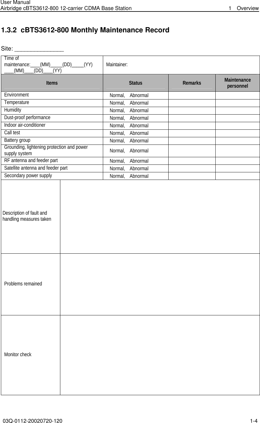
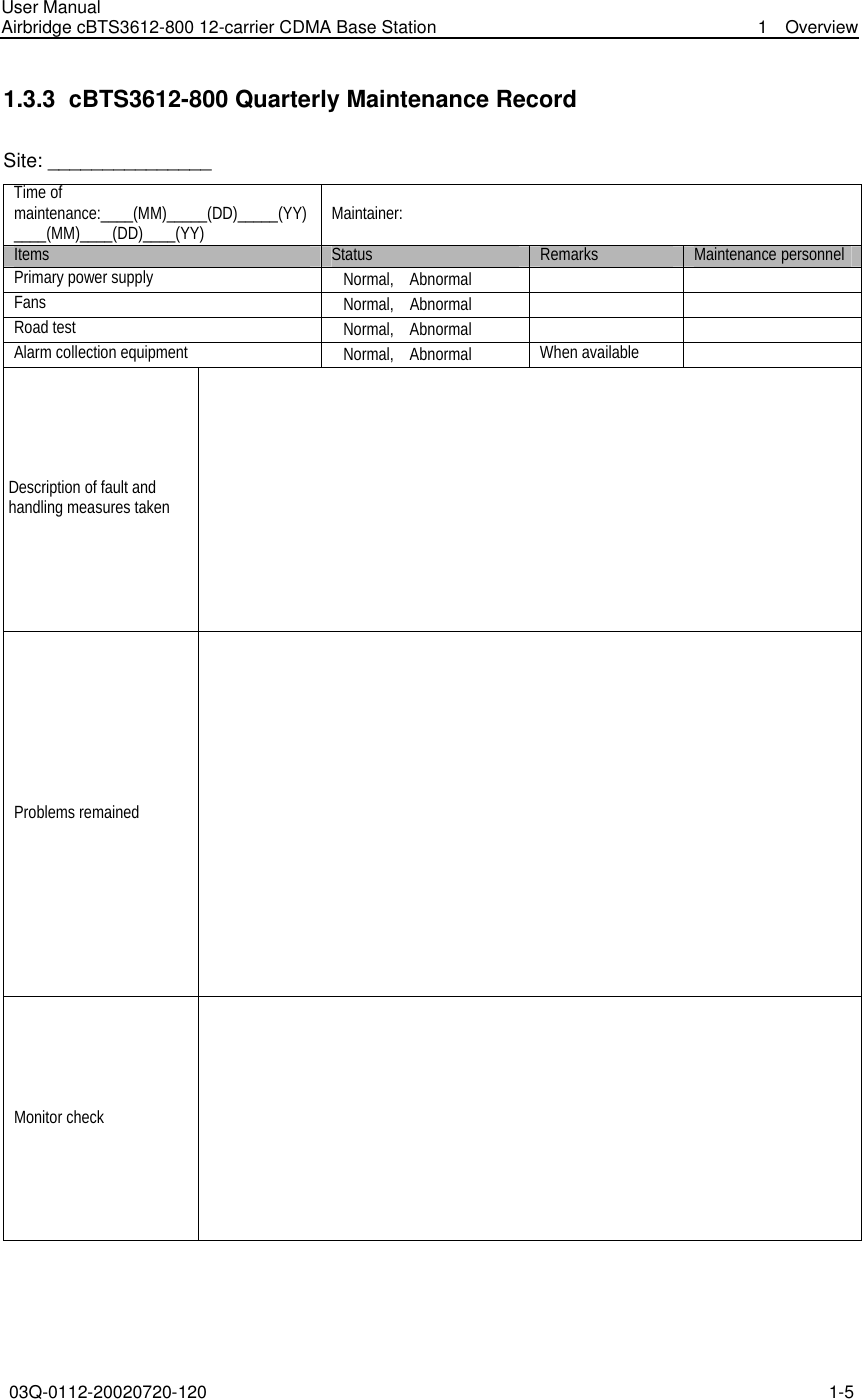
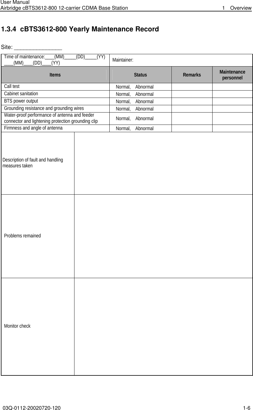
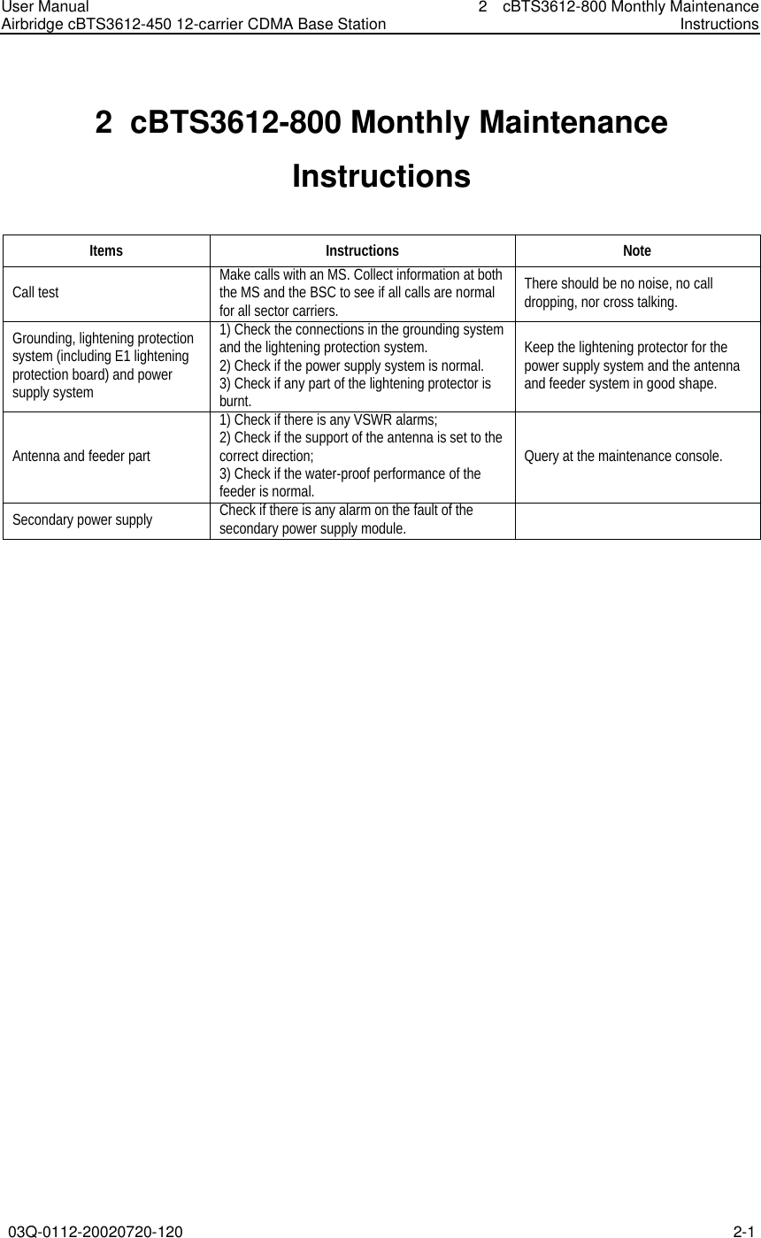
Huawei Technologies CBTS3612-800 CDMA Base Station User Manual cBTS3612 800 Routine Maintenance Instructions
Huawei Technologies Co.,Ltd CDMA Base Station cBTS3612 800 Routine Maintenance Instructions
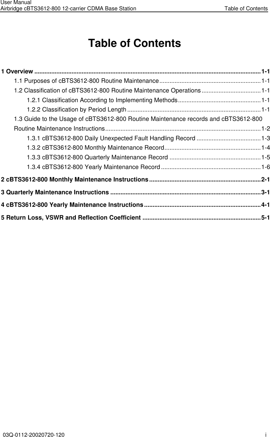
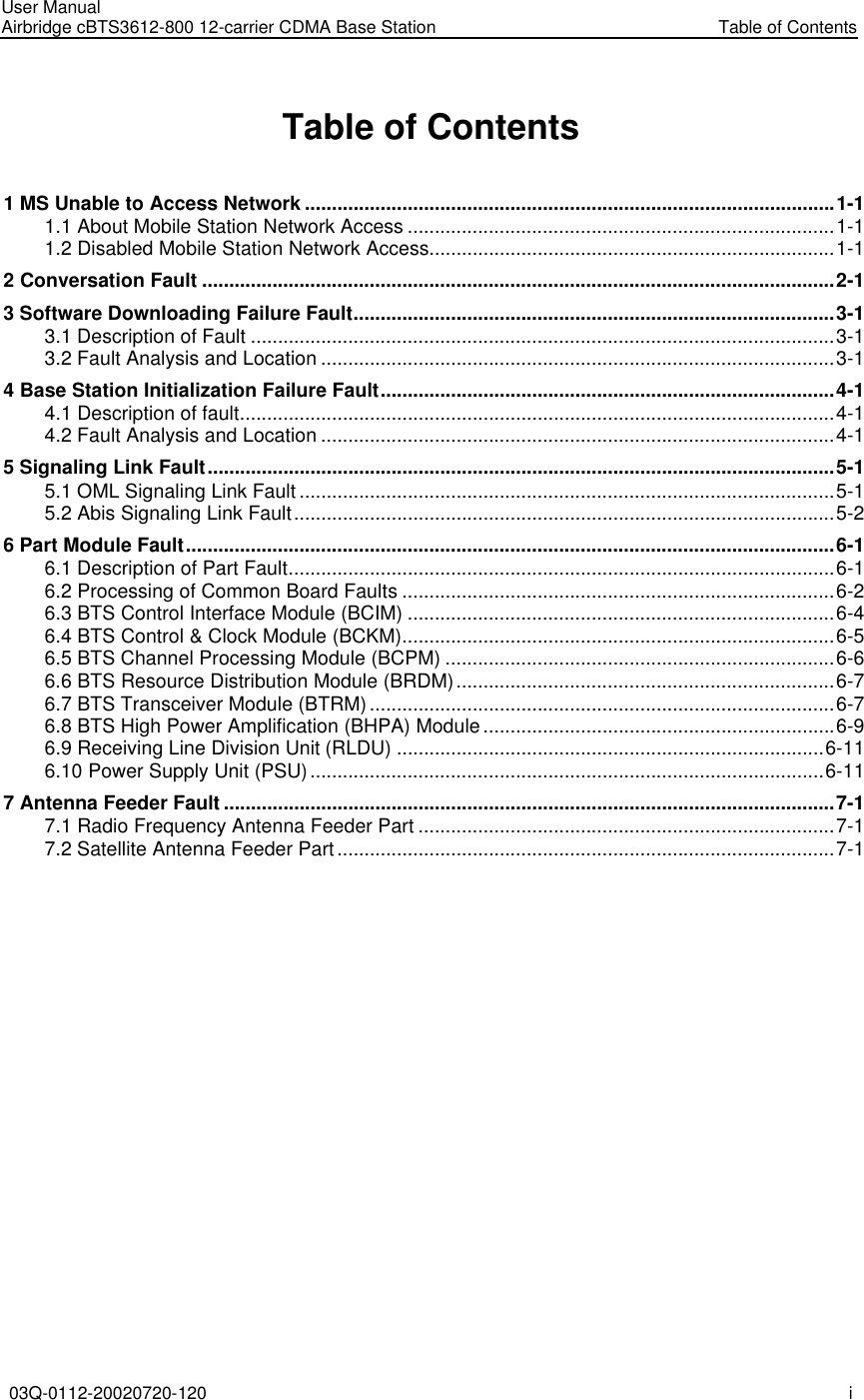
Contents
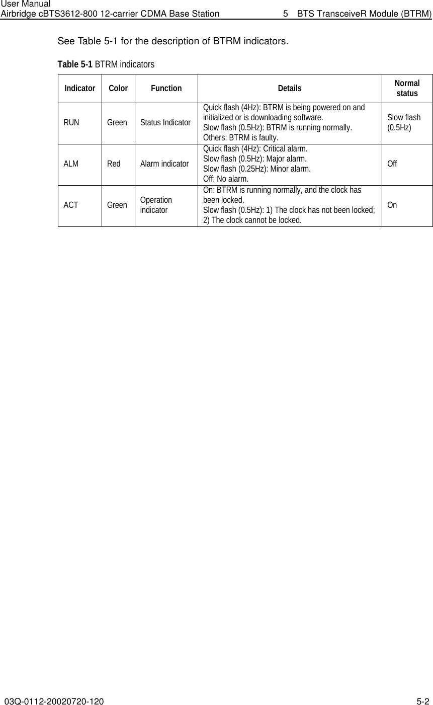
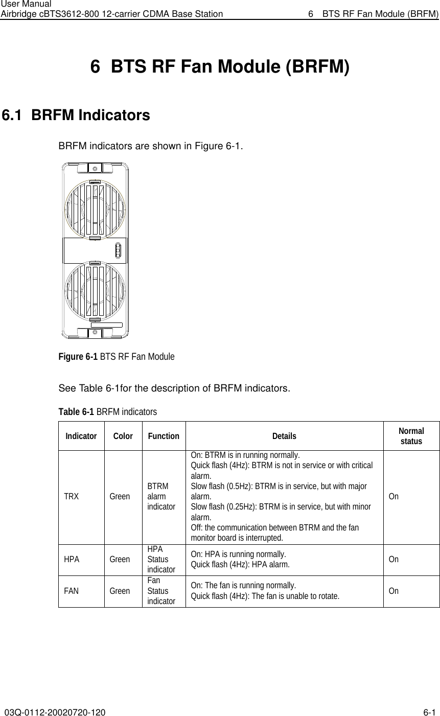
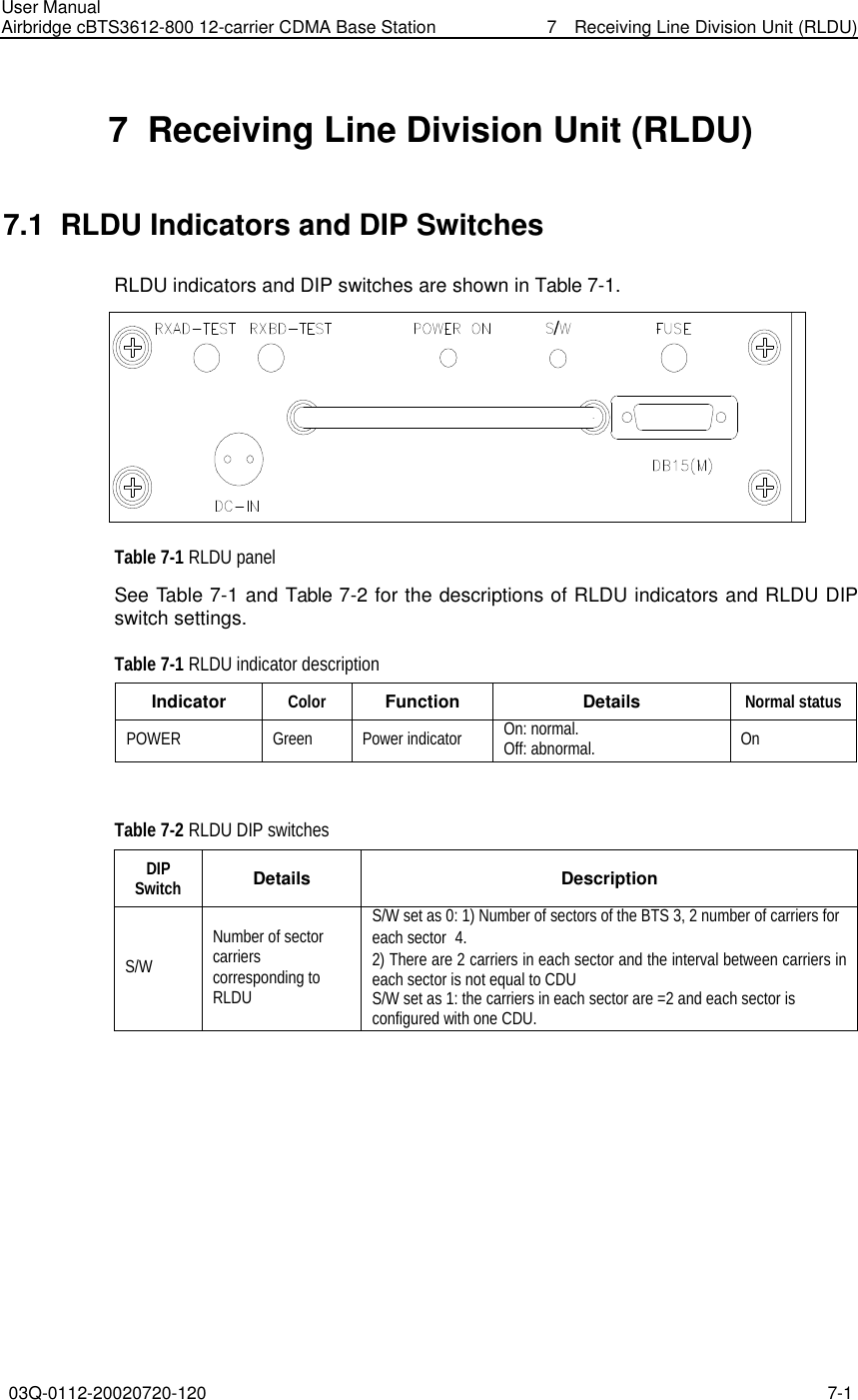
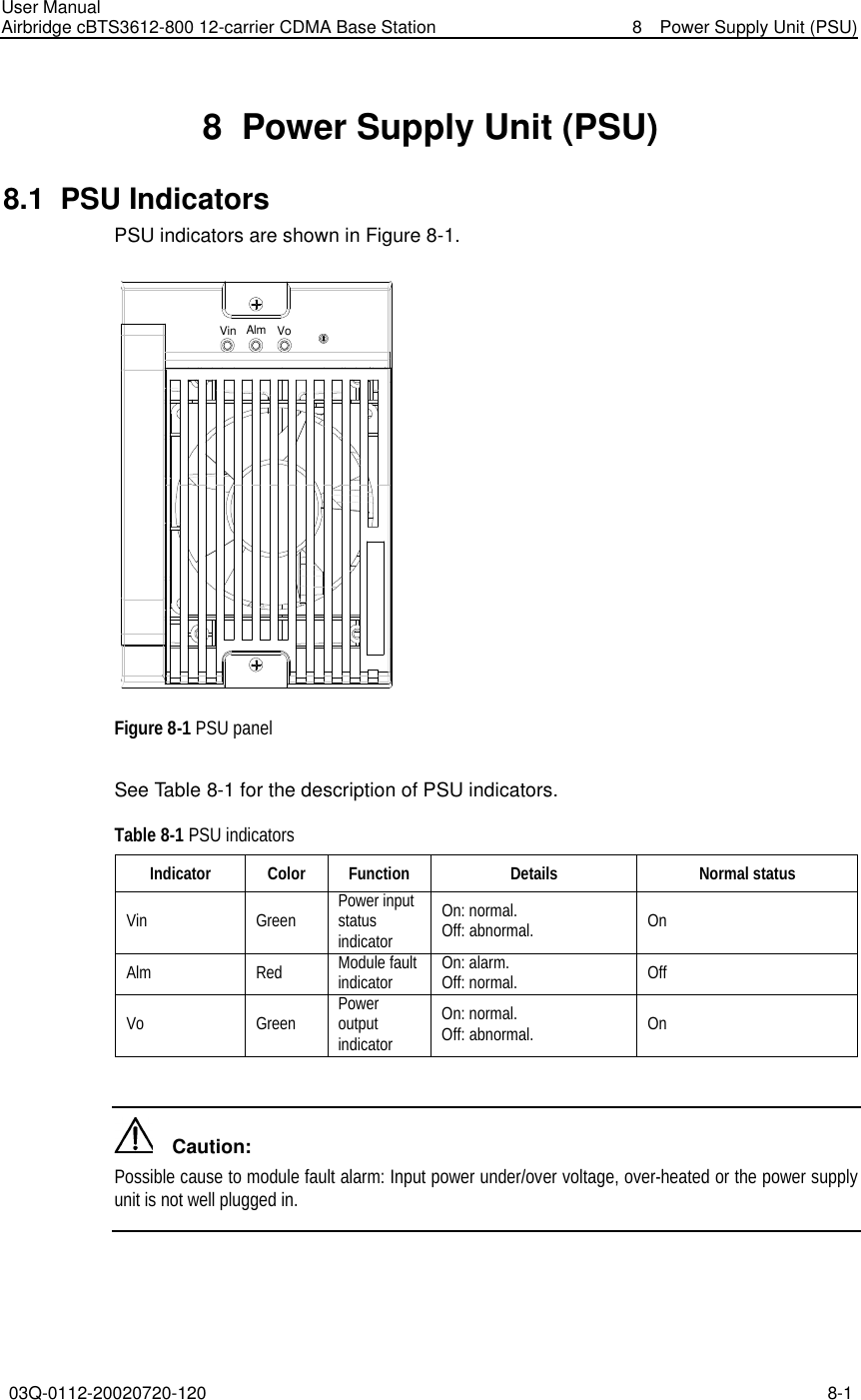
- 1. User Manual
- 2. Maintenance Manual
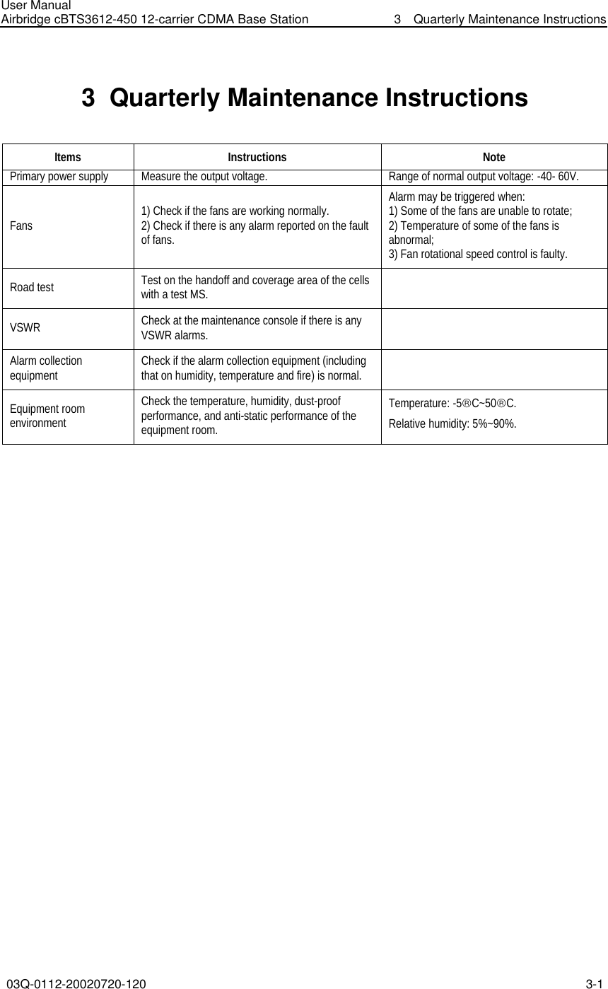
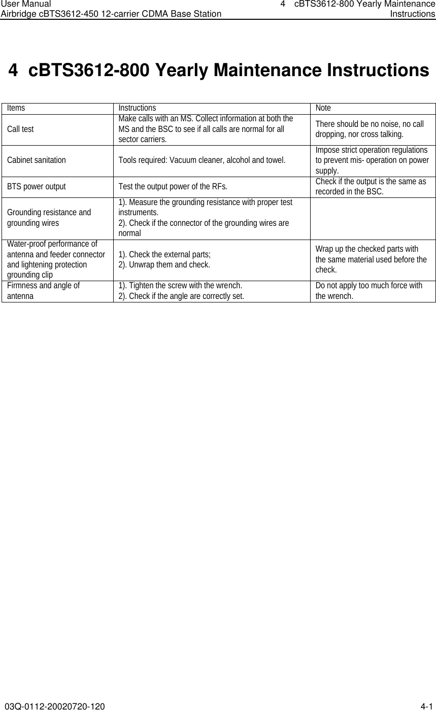
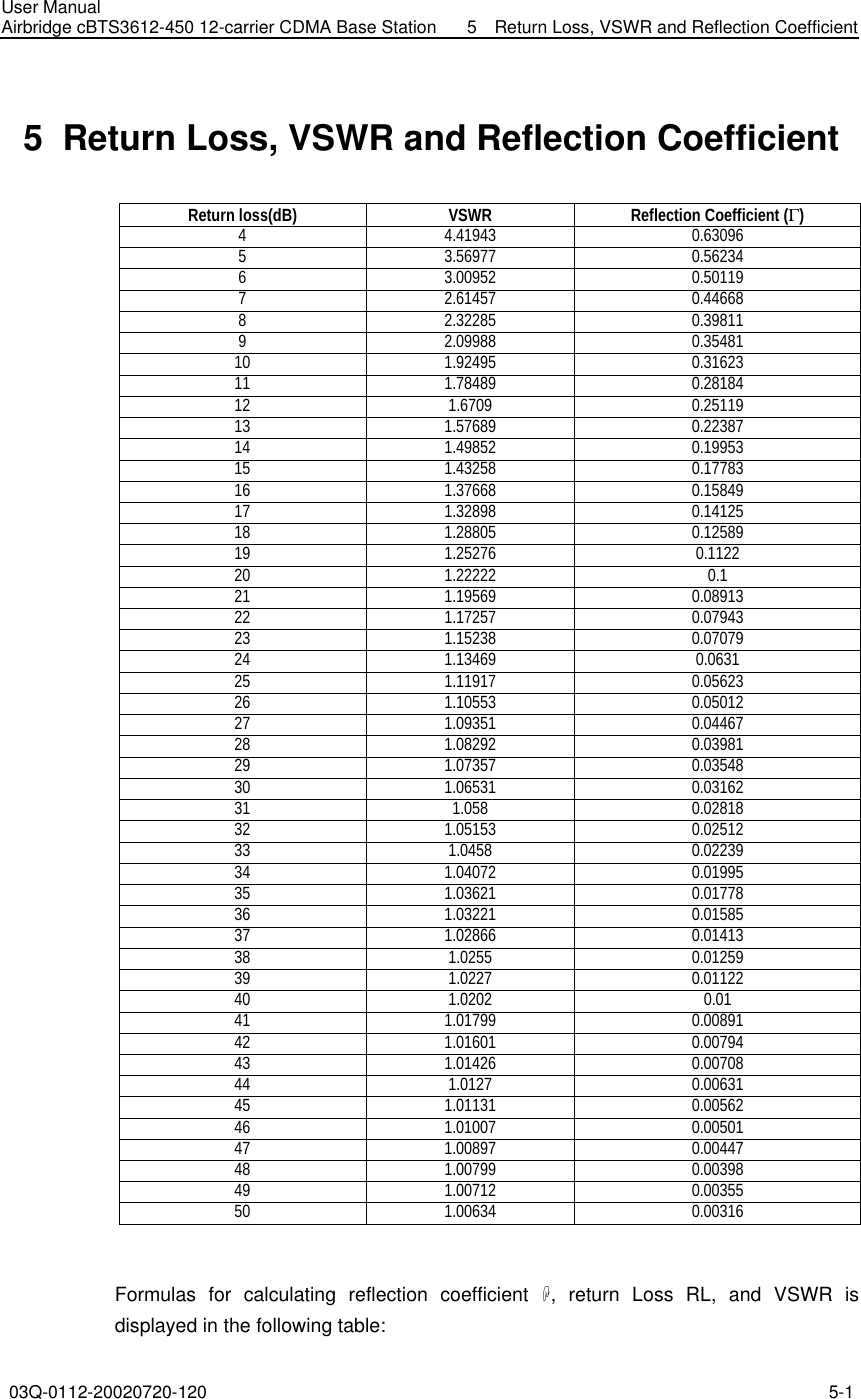
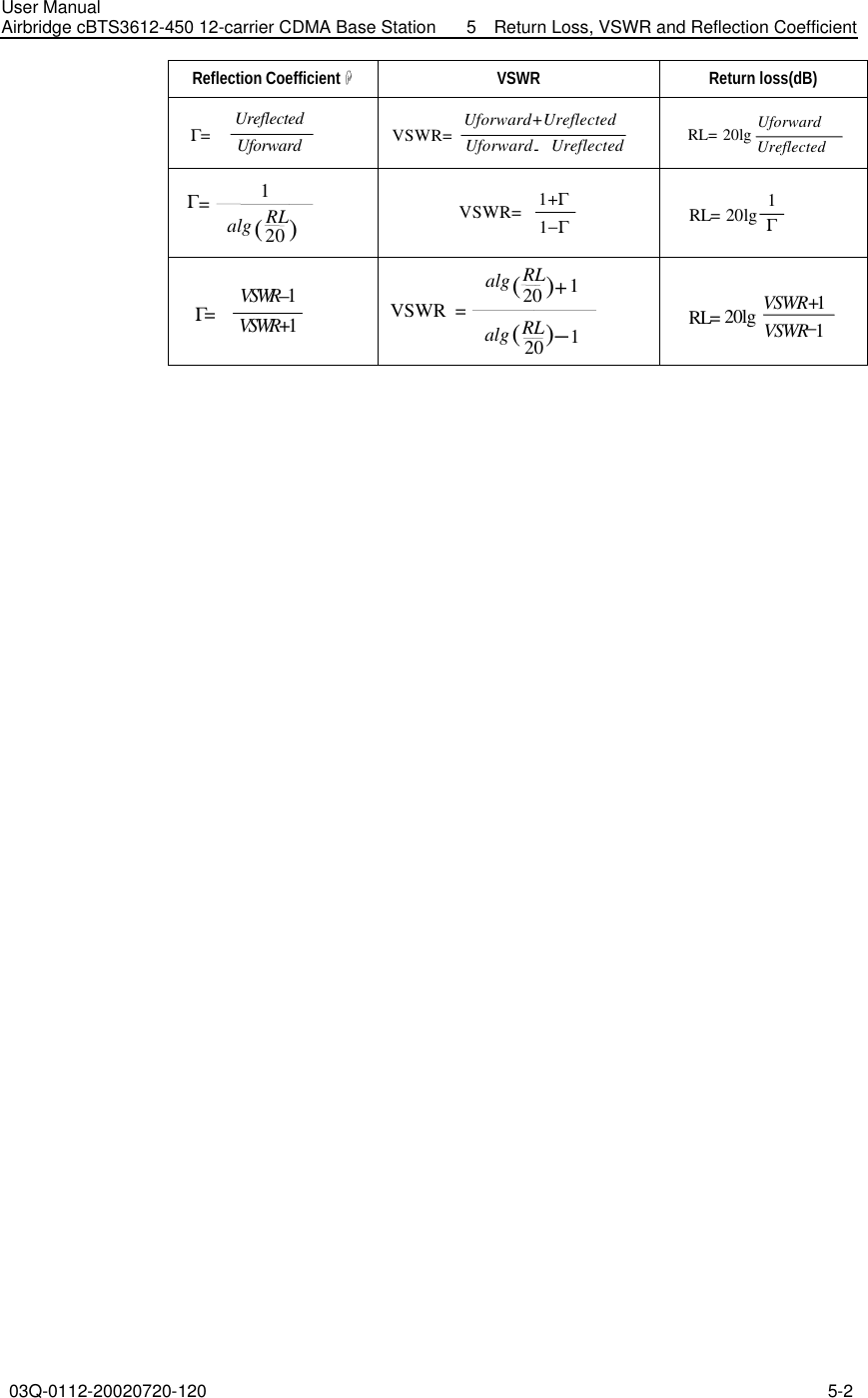
Maintenance Manual