Huawei Technologies CBTS3612-800 CDMA Base Station User Manual cBTS3612 800 Routine Maintenance Instructions
Huawei Technologies Co.,Ltd CDMA Base Station cBTS3612 800 Routine Maintenance Instructions
Contents
- 1. User Manual
- 2. Maintenance Manual
Maintenance Manual

User Manual
Airbridge cBTS3612-800 12-carrier CDMA Base Station Table of Co
ntents
03Q-0112-20020720-120 i
Table of Contents
1 Overview ......................................................................................................................................1-1
1.1 Purposes of cBTS3612-800 Routine Maintenance............................................................1-1
1.2 Classification of cBTS3612-800 Routine Maintenance Operations...................................1-1
1.2.1 Classification According to Implementing Methods.................................................1-1
1.2.2 Classification by Period Length ...............................................................................1-1
1.3 Guide to the Usage of cBTS3612-800 Routine Maintenance records and cBTS3612-800
Routine Maintenance Instructions............................................................................................1-2
1.3.1 cBTS3612-800 Daily Unexpected Fault Handling Record ......................................1-3
1.3.2 cBTS3612-800 Monthly Maintenance Record.........................................................1-4
1.3.3 cBTS3612-800 Quarterly Maintenance Record ......................................................1-5
1.3.4 cBTS3612-800 Yearly Maintenance Record...........................................................1-6
2 cBTS3612-800 Monthly Maintenance Instructions..................................................................2-1
3 Quarterly Maintenance Instructions .........................................................................................3-1
4 cBTS3612-800 Yearly Maintenance Instructions.....................................................................4-1
5 Return Loss, VSWR and Reflection Coefficient ......................................................................5-1

User Manual
Airbridge cBTS3612-800 12-carrier CDMA Base Station 1
Overview
03Q-0112-20020720-120 1-1
1 Overview
cBTS3612-800 Routine Maintenance Instructions describes in details the contents
and methods of cBTS3612-800 routine maintenance operations. It serves as a
reference in determining the routine maintenance schedule of a particular site.
cBTS3612-800 Routine Maintenance consists of:
1) Purpose of cBTS3612-800 routine maintenance;
2) Classification of cBTS3612-800 routine maintenance operations;
3) Logging of routine maintenance operations.
1.1 Purposes of cBTS3612-800 Routine Maintenance
Normal system operation of cBTS3612-800 in different running environment depends
on effective routine maintenance. cBTS3612-800 routine maintenance is intended to
detect and solve problems in due time to prevent trouble.
1.2 Classification of cBTS3612-800 Routine Maintenance
Operations
1.2.1 Classification According to Implementing Methods
I. Conventional maintenance
To observe the operation of the system, and test and analyze equipment performance
during system operation.
II. Unconventional maintenance
To test if the performance of system equipment has degraded by artificially creating
some faults and observe system performance with these faults. For example,
maintenance personnel may artificially create some faults and test if the alarm system
reports alarm correctly.
1.2.2 Classification by Period Length
I. Unscheduled maintenance
Maintenance operations incurred by equipment fault or network adjustment. For
example, maintenance tasks triggered by user complaint, damage of equipment and

User Manual
Airbridge cBTS3612-800 12-carrier CDMA Base Station 1
Overview
03Q-0112-20020720-120 1-2
line fault. Solving of problems left over by daily maintenance operations is also
regarded as unscheduled maintenance operation.
II. Daily maintenance
Maintenance tasks conducted daily. cBTS3612-800 Daily maintenance helps
maintenance personnel keep track of the operating conditions of the equipment at
any moment so that problems can be solved in time. When a problem is detected in
daily maintenance, record it in detail to help eliminate it in time.
III. Periodical maintenance
Maintenance tasks conducted regularly. Periodical maintenance helps maintenance
personnel keep track of the long-term performance of the equipment.
Periodical maintenance includes: monthly maintenance, quarterly maintenance and
yearly maintenance.
1.3 Guide to the Usage of cBTS3612-800 Routine
Maintenance records and cBTS3612-800 Routine
Maintenance Instructions
1) Note down in details the unexpected faults occurred in cBTS3612-800 daily
maintenance operations in cBTS3612-800 Daily Unexpected Fault Handling
Record for future reference. The user may modify the record according to the
actual needs, or compile the records into manuals.
2) Note down in details the actual maintenance operations carried out during
cBTS3612-800 monthly maintenance in cBTS3612-800 Monthly Maintenance
Record. For details, see cBTS 3612 Monthly Maintenance Operation Instruction.
3) Note down in details the actual maintenance operations carried out during
cBTS3612-800 quarterly maintenance in cBTS Quarterly Maintenance Record.
For details, see cBTS 3612 Quarterly Maintenance Operation Instruction.
4) Note down in details the actual maintenance operations carried out during
cBTS3612-800 yearly maintenance in cBTS3612-800 Yearly Maintenance
Record. For details, see cBTS 3612 Yearly Maintenance Operation Instruction.

User Manual
Airbridge cBTS3612-800 12-carrier CDMA Base Station 1
Overview
03Q-0112-20020720-120 1-3
1.3.1 cBTS3612-800 Daily Unexpected Fault Handling Record
Site Belong-to BSC
Time when fault
occurred: Time when fault is
solved:
Person on duty: Handled by:
Classification of fault:
Primary power supply
Secondary power supply
Base Band Subrack
RF Subrack
CDU/DFU/RLDU Subrack
Antenna & Feeder System
Others
Fault detected:
? With user complaint ? From the alarm system
? In Daily maintenance ? From other sources
Description of fault:
Alarm Handling & Result:

User Manual
Airbridge cBTS3612-800 12-carrier CDMA Base Station 1
Overview
03Q-0112-20020720-120 1-4
1.3.2 cBTS3612-800 Monthly Maintenance Record
Site: _______________
Time of
maintenance:___
_(MM)_____(DD)_____(YY)
____(MM)____(DD)____(YY) Maintainer:
Items Status Remarks Maintenance
personnel
Environment Normal, Abnormal
Temperature Normal, Abnormal
Humidity Normal, Abnormal
Dust-proof performance Normal, Abnormal
Indoor air-conditioner Normal, Abnormal
Call test Normal, Abnormal
Battery group Normal, Abnormal
Grounding, lightening protection and power
supply system Normal, Abnormal
RF antenna and feeder part Normal, Abnormal
Satellite antenna and feeder part Normal, Abnormal
Secondary power supply Normal, Abnormal
Description of fault and
handling measures taken
Problems remained
Monitor check

User Manual
Airbridge cBTS3612-800 12-carrier CDMA Base Station 1
Overview
03Q-0112-20020720-120 1-5
1.3.3 cBTS3612-800 Quarterly Maintenance Record
Site: _______________
Time of
maintenance:____(MM)_____(DD)_____(YY)
____(MM)____(DD)____(YY) Maintainer:
Items Status Remarks Maintenance personnel
Primary power supply Normal, Abnormal
Fans Normal, Abnormal
Road test Normal, Abnormal
Alarm collection equipment Normal, Abnormal When available
Description of fault and
handling measures taken
Problems remained
Monitor check

User Manual
Airbridge cBTS3612-800 12-carrier CDMA Base Station 1
Overview
03Q-0112-20020720-120 1-6
1.3.4 cBTS3612-800 Yearly Maintenance Record
Site: _______________
Time of mai
ntenance:____(MM)_____(DD)_____(YY)
____(MM)____(DD)____(YY) Maintainer:
Items Status Remarks Maintenance
personnel
Call test Normal, Abnormal
Cabinet sanitation Normal, Abnormal
BTS power output Normal, Abnormal
Grounding resistance and grounding wires Normal, Abnormal
Water-proof performance of antenna and feeder
connector and lightening protection grounding clip Normal, Abnormal
Firmness and angle of antenna Normal, Abnormal
Description of fault and handling
measures taken
Problems remained
Monitor check

User Manual
Airbridge cBTS3612-450 12-carrier CDMA Base Station 2 cBTS3612-
800 Monthly Maintenance
Instructions
03Q-0112-20020720-120 2-1
2 cBTS3612-800 Monthly Maintenance
Instructions
Items Instructions Note
Call test Make calls with an MS. Collect information at both
the MS and the BSC to see if all calls are normal
for all sector carriers.
There should be no noise, no call
dropping, nor cross talking.
Grounding, lightening protection
system (including E1 lightening
protection board) and power
supply system
1) Check the connections in the grounding system
and the lightening protection system.
2) Check if the power supply system is normal.
3) Check if any part of the lightening protector is
burnt.
Keep the lightening protector for the
power supply system and the antenna
and feeder system in good shape.
Antenna and feeder part
1) Check if there is any VSWR alarms;
2) Check if the support of the antenna is set to the
correct direction;
3) Check if the water-proof performance of the
feeder is normal.
Query at the maintenance console.
Secondary power supply Check if there is any alarm on the fault of the
secondary power supply module.

User Manual
Airbridge cBTS3612-450 12-carrier CDMA Base Station 3
Quarterly Maintenance Instructions
03Q-0112-20020720-120 3-1
3 Quarterly Maintenance Instructions
Items Instructions Note
Primary power supply Measure the output voltage. Range of normal output voltage: -40- 60V.
Fans 1) Check if the fans are working normally.
2) Check if there is any alarm reported on the fault
of fans.
Alarm may be triggered when:
1) Some of the fans are unable to rotate;
2) Temperature of some of the fans is
abnormal;
3) Fan rotational speed control is faulty.
Road test Test on the handoff and coverage area of the cells
with a test MS.
VSWR Check at the maintenance console if there is any
VSWR alarms.
Alarm collection
equipment Check if the alarm collection equipment (including
that on humidity, temperature and fire) is normal.
Equipment room
environment
Check the temperature, humidity, dust-proof
performance, and anti-static performance of the
equipment room.
Temperature: -5C~50C.
Relative humidity: 5%~90%.

User Manual
Airbridge cBTS3612-450 12-carrier CDMA Base Station 4 cBTS3612-800
Yearly Maintenance
Instructions
03Q-0112-20020720-120 4-1
4 cBTS3612-800 Yearly Maintenance Instructions
Items Instructions Note
Call test Make calls with an MS. Collect information at both the
MS and the BSC to see if all calls are normal for all
sector carriers.
There should be no noise, no call
dropping, nor cross talking.
Cabinet sanitation Tools required: Vacuum cleaner, alcohol and towel. Impose strict operation regulations
to prevent mis- operation on power
supply.
BTS power output Test the output power of the RFs. Check if the output is the same as
recorded in the BSC.
Grounding resistance and
grounding wires
1). Measure the grounding resistance with proper test
instruments.
2). Check if the connector of the grounding wires are
normal
Water-proof performance of
antenna and feeder connector
and lightening protection
grounding clip
1). Check the external parts;
2). Unwrap them and check.
Wrap up the checked parts with
the same material used before the
check.
Firmness and angle of
antenna 1). Tighten the screw with the wrench.
2). Check if the angle are correctly set. Do not apply too much force with
the wrench.

User Manual
Airbridge cBTS3612-450 12-carrier CDMA Base Station 5 Return Loss, VSWR and Reflection Coefficient
03Q-0112-20020720-120 5-1
5 Return Loss, VSWR and Reflection Coefficient
Return loss(dB) VSWR Reflection Coefficient (Γ)
4 4.41943 0.63096
5 3.56977 0.56234
6 3.00952 0.50119
7 2.61457 0.44668
8 2.32285 0.39811
9 2.09988 0.35481
10 1.92495 0.31623
11 1.78489 0.28184
12 1.6709 0.25119
13 1.57689 0.22387
14 1.49852 0.19953
15 1.43258 0.17783
16 1.37668 0.15849
17 1.32898 0.14125
18 1.28805 0.12589
19 1.25276 0.1122
20 1.22222 0.1
21 1.19569 0.08913
22 1.17257 0.07943
23 1.15238 0.07079
24 1.13469 0.0631
25 1.11917 0.05623
26 1.10553 0.05012
27 1.09351 0.04467
28 1.08292 0.03981
29 1.07357 0.03548
30 1.06531 0.03162
31 1.058 0.02818
32 1.05153 0.02512
33 1.0458 0.02239
34 1.04072 0.01995
35 1.03621 0.01778
36 1.03221 0.01585
37 1.02866 0.01413
38 1.0255 0.01259
39 1.0227 0.01122
40 1.0202 0.01
41 1.01799 0.00891
42 1.01601 0.00794
43 1.01426 0.00708
44 1.0127 0.00631
45 1.01131 0.00562
46 1.01007 0.00501
47 1.00897 0.00447
48 1.00799 0.00398
49 1.00712 0.00355
50 1.00634 0.00316
Formulas for calculating reflection coefficient G, return Loss RL, and VSWR is
displayed in the following table:

User Manual
Airbridge cBTS3612-450 12-carrier CDMA Base Station 5 Return Loss, VSWR and Reflection Coefficient
03Q-0112-20020720-120 5-2
Reflection Coefficient G VSWR Return loss(dB)
Γ=Ureflected
Uforward
VSWR=
Uforward+Ureflected
Uforward-Ureflected RL=Uforward
Ureflected
20lg
Γ=1
alg( )
RL
20
VSWR=1+Γ
1−Γ
RL=1
Γ
20lg
Γ=VSWR−1
VSWR+1
VSWR =
alg( )
RL
20 −1
alg( )
RL
20 +1
RL=VSWR+1
VSWR−1
20lg

User Manual
Airbridge cBTS3612-800 12-carrier CDMA Base Station
Table of Contents
03Q-0112-20020720-120 i
Table of Contents
1 MS Unable to Access Network ..................................................................................................1-1
1.1 About Mobile Station Network Access ...............................................................................1-1
1.2 Disabled Mobile Station Network Access...........................................................................1-1
2 Conversation Fault .....................................................................................................................2-1
3 Software Downloading Failure Fault.........................................................................................3-1
3.1 Description of Fault ............................................................................................................3-1
3.2 Fault Analysis and Location ...............................................................................................3-1
4 Base Station Initialization Failure Fault....................................................................................4-1
4.1 Description of fault..............................................................................................................4-1
4.2 Fault Analysis and Location ...............................................................................................4-1
5 Signaling Link Fault....................................................................................................................5-1
5.1 OML Signaling Link Fault ...................................................................................................5-1
5.2 Abis Signaling Link Fault....................................................................................................5-2
6 Part Module Fault........................................................................................................................6-1
6.1 Description of Part Fault.....................................................................................................6-1
6.2 Processing of Common Board Faults ................................................................................6-2
6.3 BTS Control Interface Module (BCIM) ...............................................................................6-4
6.4 BTS Control & Clock Module (BCKM)................................................................................6-5
6.5 BTS Channel Processing Module (BCPM) ........................................................................6-6
6.6 BTS Resource Distribution Module (BRDM)......................................................................6-7
6.7 BTS Transceiver Module (BTRM)......................................................................................6-7
6.8 BTS High Power Amplification (BHPA) Module.................................................................6-9
6.9 Receiving Line Division Unit (RLDU) ...............................................................................6-11
6.10 Power Supply Unit (PSU)...............................................................................................6-11
7 Antenna Feeder Fault .................................................................................................................7-1
7.1 Radio Frequency Antenna Feeder Part .............................................................................7-1
7.2 Satellite Antenna Feeder Part............................................................................................7-1

User Manual
Airbridge cBTS3612-450 12-carrier CDMA Base Station 1 MS Unable to Access Network
03Q-0112-20020720-120 1-1
1 MS Unable to Access Network
1.1 About Mobile Station Network Access
Once powered on, an MS first enters the System Determination Substate and then
selects an analog system or CDMA system based on the parameters predefined in
the mobile station by the user. If the CDMA system is selected, the mobile station will
attempt to capture it and enters the Pilot Channel Acquisition Substate.
In this substate, the mobile station will first search the primary frequency bands for all
pilot channels (search all PN offsets), and captures the strongest pilot channel. If
there are no pilot channels captured on the basic frequency bands, the mobile station
will tune to an auxiliary frequency band and continue searching for a pilot channel.
When the mobile station has captured a pilot channel, it enters the Sync Channel
Acquisition Substate.
In this substate, the mobile station will attempt to obtain a sync channel and receive
synchronization messages. And by means of these messages, the mobile station can
obtain the pilot PN offset, network system identity, long code status, system time,
paging channel rate, frequency bands on which basic paging channels are, etc. Once
this information is obtained, the mobile station will enter the Timing Change Substate.
In this substate, the mobile station will use the pilot PN offset, long code status
received in the sync channel messages and synchronizes the long code status and
system timing with the CDMA system timing. After that, the mobile station will enter
the Mobile Station Idle State.
In the idle status, the mobile station needs to receive the overhead messages on the
paging channels. The mobile station cannot work normally unless it has received
correct Overhead Messages within the specified period of time.
If all the above conditions are satisfied, the mobile station will normally gain access to
a network.
1.2 Disabled Mobile Station Network Access
1.2.1 Description of Fault
When started, the mobile station cannot access the CDMA network.
1.2.2 Fault Analysis and Location
Before locating any base station fault, make sure that the parameters for a mobile
station are correctly set, such as the basic frequency band, auxiliary frequency band,
SID, NID, etc.
I. Base station not in service
The base station is not in service and the mobile station cannot gain access to a
network. The causes for the base station not to be in service include:

User Manual
Airbridge cBTS3612-450 12-carrier CDMA Base Station 1 MS Unable to Access Network
03Q-0112-20020720-120 1-2
1) The base station equipment in a faulty status makes the base station fail to be in
service.
2) The base station has not obtained correct configuration data, which leads to the
base station not being in service.
For the troubleshooting details, please refer to "4 Base Station Initialization Failure
Fault".
II. Abis signaling link fault
Abis signaling link fault will disable the network access of a mobile station.
1) If any fault occurs to the Abis signaling link after a base station has been in
service, BSC cannot implement any logical configuration for the base station and
accordingly the mobile station cannot gain access to a network.
2) If a base station has obtained its logic configuration, when any fault occurs to the
Abis signaling link, the base station will cut off the transmission signals of BTRM
corresponding to all sector carriers and this makes a mobile station unable to
gain access to a network.
At an OMC or near-end maintenance console of a base station, query the current
alarm of the base station to make sure whether there exists any "Abis signaling link
fault" alarm.
For the troubleshooting details, please refer to "5.2 Abis signaling link fault".
III. A cell has not obtained the logic configuration of BSC
1) If a cell has no logical configuration, that is to say, such common channels as
pilot, synchronization, paging, etc. have not been established or overhead
messages not updated, the mobile station naturally cannot gain access to a
network.
View the confiuguration process report of a cell at the OMC maintenance console. If
the cell does not report the process of "Common channel successfully established"
and "Overhead message successfully updated", it shows that the cell has no logic
configuration.
2) Unavailable physical equipment or operation & maintenanace (for example,
deletion of the equipment) results in the deletion of a logic cell, therefore the
mobile station cannot gain access to a network.
View the configuration process report of a cell at an OMC maintenance console. If the
cell reports the process report of "Cell deleted", it shows that the cell has been
deleted.
In addition, you may query whether a cell has its logic configuration via the "Cell
Status Query" command at the OMC maintenance console.
If a cell has not obtained its logic configuration, then check point by point:
l Whether the BTRM used in this cell works normally.
l Whether the BCPM used in this cell works normally.
l Whether the corresponding BRDM works normally.
l Whether the optical fiber of BTRM and that of BRDM are correctly connected.
l Whether BCIM works normally.
l Whether the Abis signaling link is in connected status.
l Whether BSC works normally.
l Check the configuration parameters of BTS and BSC and make sure that they
are in accordance.
If any problem is found at some step, handle it according to the corresponding
chapter or section. For example, a BTRM module fault should be handled as
described in "6.5 BTS Transceiver Module (BTRM)".

User Manual
Airbridge cBTS3612-450 12-carrier CDMA Base Station 1 MS Unable to Access Network
03Q-0112-20020720-120 1-3
IV. This cell is in blocked status
If you see at the OMC maintenance console that the logic configuration of a cell has
been completed, but the mobile station still cannot gain access to a network, then you
can check whether this cell is in blocked status.
When a cell is in blocked status, the base station will cut off the transmission signals
of BTRM corresponding to this cell carrier and this makes the mobile station unable to
gain access to a network.
You may query BTRM status at the OMC maintenance console to see whether the
BTRM corresponding to this cell has been blocked.
If the cell is in blocked status, the mobile station cannot gain access to a network until
the user has unblocked it.
V. Abnormal receiving channel
If you see at the OMC maintenance console that the logic configuration of a cell has
been completed, but the mobile station still cannot gain access to a network, then you
can check whether the receiving channel of a base station is abnormal.
An abnormal BS receiving channel will lead to excessive receiving error codes and
frequent mobile station dropouts. The mobile station, when started, will send a
power-on registration message to the system. However, the base station cannot
receive this registration message because of a faulty receiving channel. Thus, the
base station will not send any base station answer instruction to this mobile station,
which leads to failed registration of this mobile station. Because of failed registration,
the mobile station enters the system defining sub-status and recaptures the system.
When the system is captured, the mobile station will start again the power-on
registration. Such things happen repeatedly, so that the mobile station cannot gain
access to a network.
You may test the mobile station via CDMA and trace air interface messages. If the
mobile station sends "Registration message" but does not receive any "Base station
answer instruction" message, it shows that some fault has occurred to the reverse
receiving channel of the base station.
If there exists any receiving channel abnormality, you may check point by point as
follows and make judgements by viewing related indicators, querying the board status
and alarm information, etc.
l Whether the CDU, RLDU and BTRM module are well installed and the panel
screws are correctly fastened.
l Whether the antenna feeder connection is correct.
l Whether the CDU works normally.
l Whether the RLDU works normally.
l Whether the configuration selection switch "S/W" on the RLDU panel is set
correctly. For the description of RLDU panel switch, please refer to "Board
Indicator and DIP Switch" of "Base Station Maintenance" part in the user
manual.
l Whether the BTRM works normally.
l Whether the BCPM works normally.
l Whether the blind plugs of various modules of the receiving channel are normally
connected and there is any loosening.
l Whether the physical configuration data of the base station are correct, including
the cell parameter, backward search parameters, etc.

User Manual
Airbridge cBTS3612-450 12-carrier CDMA Base Station 1 MS Unable to Access Network
03Q-0112-20020720-120 1-4
If any problem is found at some step, handle it according to the corresponding
chapter or section. For example, a BTRM module fault should be handled as
described in "6.5 Transceiver Module (BTRM)".
VI. Abnormal transmission channel
Transmission activation (BTRM), BHPA, CDU and antenna feeder form the
transmission channel. But an abnormal transmission channel will lead to no output
signal from the base station or abnormal output signals. In this case, you may see at
the OMC maintenance console that the logic configuration of a cell has been
completed, but the mobile station still cannot gain access to a network. Then, you
may check point by point as follows:
l Whether the CDU, BHPA module and BTRM module are well installed and the
panel screws correctly fastened.
l Whether BTRM transmission activation part works normally.
l Whether the CDU works normally.
l Whether BTRM and BHPA are normally connected.
l Whether the BHPA works normally.
l Whether BHPA and CDU are connected.
l Whether the feeder connection between CDU and the cabinet top is normal.
l Whether the feeder connection between the cabinet top and the antenna is
normal.
l Whether the blind plugs of various modules of the receiving channel are normal
and whether there is any loosening.
l Whether the antenna is correctly installed.
l Whether there is any standing wave ratio alarm.
If any problem is found at some step, handle it according to the corresponding
chapter or section. For example, a BTRM module fault should be handled as
described in "6.5 Transceiver Module (BTRM)".
VII. The cell gain and common channel gain are not correctly set
You may see at the OMC maintenance console that the logic configuration of a cell
has been completed, but the mobile station still cannot gain access to a network. In
this case, you may check whether various gain parameters during the cell
configuration are correctly set.
When the cell is logically configured, such parameters as the sector gain, carrier gain,
pilot channel gain, synchronization channel gain, paging channel gain, etc. must be
configured. If these parameters are improperly set (for example, excessively small),
the mobile station will not be able to capture the corresponding common channel and
this makes the mobile station unable to gain access to a network.
Make sure whether the gain parameters contained in Abis-Cell Setup message are
reasonable via the Abis interface message tracing tool. If unreasonable, the data
configuration table of BSC must be modified and the gain parameters be configured
again.
VIII. The overhead message content is not correct
You may see at the OMC maintenance console that the logic configuration of a cell
has been completed, but the mobile station still cannot gain access to a network. In
this case, you may check whether the overhead message content is correct.
Upon entering the idle status, the mobile station must receive all overhead messages
(including at least the following four: the access parameter message, system
parameter message, CDMA channel list message and adjacent area list message.

User Manual
Airbridge cBTS3612-450 12-carrier CDMA Base Station 1 MS Unable to Access Network
03Q-0112-20020720-120 1-5
Other overhead messages depend on the setting of network parameters) configured
in the whole system within the specified period of time. Otherwise, the mobile station
cannot gain access to a network.
In addition, the value of the parameters in each overhead message will also make the
mobile station unable to gain access to a network and needs confirming carefully.
With the air interface message signaling analyzer, you may check whether the mobile
station has received the overhead messages configured in the whole system. In
addition, you should check whether the parameter value of each overhead message
is correct. If not, you may modify the data configuration table of BSC and update the
overhead message again.

User Manual
Airbridge cBTS3612-450 12-carrier CDMA Base Station 2
Conversation Fault
03Q-0112-20020720-120 2-1
2 Conversation Fault
For the content in this chapter, please refer to related parts in BSC Maintenance
Manual.

User Manual
Airbridge cBTS3612-450 12-carrier CDMA Base Station 3 Software
Downloading Failure Fault
03Q-0112-20020720-120 3-1
3 Software Downloading Failure Fault
3.1 Description of Fault
I. FTP client login failure
OMC sends a command to an OMU (a base station operation & maintenance unit
running on BCKM) to start downloading files from BAM. The OMU receives the
command, but cannot log on to the FTP server of BAM. In this case, OMC
background receives the abnormal halt message of OMU and FTP client login fails.
II. Abnormal halt of file loading by the board
When some board software is downloaded and activated by means of OMC, it is
found that the whole stage from the starting of downloading and activating to the
waiting for the activation report is normal. Then, OMC receives the abnormal halt
message of OMU and file loading is abnormally halted by the board.
3.2 Fault Analysis and Location
I. FTP client login failure
1) Check whether the FTP server on BAM is in Stop status or correctly set.
First view whether the FTP server is in Stop status. If it runs normally, then check
whether the FTP server is set correctly. FTP server settings include the following four:
user name, user password, user accessible path and access authority. Any setting
error will lead to failed login or failed board software loading.
When a base station loads software, the above four items are set as follows:
User name: OMU
Password: OMU
Access path: Required to include the file path specified in the software uploading/downloading
command.
Access authority: The directory to be uploaded must be set as readable and writable.
2) Check whether OMU BOOTP is normal
OMU obtains the IP address of a base station by means of BOOTP request. If this
process fails, OMU will not be able to obtain the IP address of the base station and
naturally cannot log on to the FTP server of BAM. Usually, a disconnected link, wrong
route or configuration data error may lead to the failed BOOTP process. These should
be eliminated one by one. For details, please refer to "5.1 OML Signaling Fault".
II. Abnormal halt of file loading by the board
All load files must have the file headers in stipulated format, in which the file ID and
file version must be consistent with the corresponding field in the activation command
sent by OMC. Otherwise, the board will consider the software actually downloaded as
inconsistent with that to be loaded and reports abnormality error.

User Manual
Airbridge cBTS3612-450 12-carrier CDMA Base Station 4 Base Stat
ion Initialization Failure Fault
03Q-0112-20020720-120 4-1
4 Base Station Initialization Failure Fault
4.1 Description of fault
The base station, when powered on, fails to be initialized, which makes it unable to be
in normal service. Once such a fault occurs, the ACT indicators on some boards
flashes quickly.
4.2 Fault Analysis and Location
There are quite a lot of factors leading to failed initialization of a base station, but in
summary, the following aspects can be taken into consideration to locate and solve
those problems.
I. Link fault
The prerequisite for successful initialization of a base station is that an ATM link
should be successfully established between the BCIM of the base station and XIE
board of BSC. And the BCIM board of the base station is required to successfully
intercept the link configuration of the XIE board of BSC and establish the
corresponding IMA/UNI link. If the BSC configuration data are wrong (or no
corresponding physical link configured), then BCIM cannot make a successful
interception and this leads to failed link establishment.
In addition, the base station BOOTP failure and failed establishment of an OML may
lead to unsuccessful initialization of the base station. For such a case, please refer to
"5.1 OML Fault".
II. Clock fault
After a base station has successfully established an OML, BSC will send
corresponding configuration data. In this case, some boards of the base station must
have correct clock signals before they are in normal service. Thererfore, check is
necessary when a base station fails to be initialized after the configuration is sent.
1) Whether the clock signals of a base station are correct.
2) Whether the clock output of BCKM is normal.
3) Whether BCKM and GPS or GLONASS antenna are well connected.
4) Whether the captured GPS or GLONASS satellites are more than 4.
For the above (1) and (2), please refer to "6.2 BTS Control & Clock Module
(BCKM)". As for (3), please refer to "7.2 Satellite Antenna Feeder Part". (4) may be
caused by geographical position. If it is found that the captured GPS or GLONASS
satellites are not more than 4, the base station may not be able to obtain reliable
clock signals.
III. BCPM Configuration Data Error
If the BCPM board configuration data sent by a base station are wrong, the base
station may fail to be initialized. Please locate such a fault as follows:
1) Whether BCPM board No. and its physical slot form one-to-one correspondence.
2) Whether the cell parameters of a channel board are correctly configured.

User Manual
Airbridge cBTS3612-450 12-carrier CDMA Base Station 4 Base Stat
ion Initialization Failure Fault
03Q-0112-20020720-120 4-2
3) Whether the chip parameters of a channel board are correctly configured.
4) Whether the daisy chain of a channel board is correct.
5) Whether the traffic link of a channel board is correctly configured.
Confirm the above and configure correct data again.
IV. BTRM configuration data error
BTRM configuration data error may also lead to failed initialization of a base station,
therefore various parameters must be carefully checked, such as the board No., cell
No., cell resource pool No., optical interface No., ect. Of BTRM. Please confirm them
and configure correct data again.
V. Board physical connection error
That a base station fails to be initialized as a result of physical connection error may
be caused by the following:
1) Various boards or modules have not been correctly installed and need installing
well.
2) The optical fiber connection between BRDM and BTRM is faulty. Please refer to
"6.2 Processing of Common Board Faults".

User Manual
Airbridge cBTS3612-450 12-carrier CDMA Base Station 5 Signaling Link Fault
03Q-0112-20020720-120 5-1
5 Signaling Link Fault
5.1 OML Signaling Link Fault
5.1.1 Description of Fault
After a base station is powered on, such faults occurred, for example, failed BOOTP,
failed establishment of the OML with OMC or OML broken link alarm during the
normal operation of a base station. In this case, you may observe at the near-end and
OMC far end maintenance consoles of a base station that the "OML Signaling Link
Fault" alarm occurs.
5.1.2 Fault Analysis and Location
The OML connection of a base station begins with the BCKM of the base station,
passes BCIM of the base station, the XIE and MUX of BSC, LPU and MPU of the
switching frame, and ends with the background (BAM). Therefore, any chain fault in
this route may lead to an OML fault in the base station.
I. Communication link fault between the BCKM board and BCIM board
For details, please refer to the board communication link fault in "6.2 Processing of
Common Board Faults".
II. Abnormal IMA group or UNI link status
If the physical layer of an OML is connected by means of E1, it can be configured as
IMA mode or UNI mode as required. If there is incorrect IMA group status or UNI link
status, OML fault may occur.
At the far end OMC client or near-end maintenance console, you may query the
special status of a board to obtain the IMA group status or UNI link status.
If there is abnormal IMA group status or UNI link status, please check point by point:
l Whether E1 link is normal. This can be done by means of loopback test.
l In the case of IMA, it is necessary to make sure whether the N pair of E1s in the
BSC IMA group corresponds to that in the base station IMA group (N=1~8).
l Check whether the IMA group configuration of BSC and that of the base station
are consistent.
III. VCI configuration error of CMUX board of BSC
The prerequisite for an OML to be established in a base station is that there should
be a successful BOOTP request, which demands a unique MAC address field. If
there are repeated data when BSC configures MUX with VCI information, the MAC
field in the BOOTP request packet may be made not unique. Thus, the base station
BOOTP fails and the OML cannot be established.
Processing method: check the configuration data of BSC to ensure the correctness
and uniqueness of the configuration data.

User Manual
Airbridge cBTS3612-450 12-carrier CDMA Base Station 5 Signaling Link Fault
03Q-0112-20020720-120 5-2
IV. Route information configuration error
The OML in a base station bridges two IP gateways, one being MPU of BSC
switching frame and the other being MUX of BSC BM frame. And the uplink and
downlink route table information are different from each other. If any gateway is
configured with wrong information, the OML will fail to be established in a base station.
What is typical is that TCP connection of an OML cannot be established after the
base station BOOTP request has succeeded. For such a case, please check in turn
the route information of the above-mentioned chains. First check the route
information of BAM to see whether it can correctly connect with the MPU of a
switching frame. Then, check the route inforamtion of MUX to see whether it can
connect downward with a base station and upward with a BAM. If the route
configuration is wrong, then modify the route configuration of the switching frame and
the MUX route data of BSC.
V. Related data configuration error of a far end OMC
During the OML establishment in a base station, the far end OMC acts as both
BOOTP Server and TCP Server. During the base station BOOTP, the OMC is
required to configure local BOOTP related information based on the data configured
in BSC. And this group of BOOTP information is required to be unique and consistent
with the data configured in BSC.
If an OMC is configured with wrong BOOTP information, the MAC field contained in
BOOTP request packet of a base station will not correspond to the BOOTP
information configured in OMC. And this results in failed BOOTP request of a base
station and an OML cannot be established.
Solution: Query the BOOTP information of this base station at the far end OMC,
compare it with the data configured in BSC and modify those inconsistent ones.
VI. Far end OMC fault
During the OML establishment in a base station, the far end OMC acts as both
BOOTP Server and TCP Server. Therefore, any far end OMC fault may lead to the
OML fautl of the base station. Possible OMC faults include:
1) BAM halts or BAM process is not started. In this case, it is necessary to restart
BAM or start a BAM process.
2) The loading process of BAM is abnormal. In this case, it is necessary to restart
the loading process of BAM.
3) The low layer communication process (Exchange Server) of BAM is abnormal. In
this case, it is necessary to restart it.
5.2 Abis Signaling Link Fault
5.2.1 Description of Fault
When a base station is in service, the Abis signaling link between the base station
and BSC cannot be established or broken link occurs to the running base station. And
you can observe at the OMC alarm console that the "Abis signaling link fault" alarm
occurs.

User Manual
Airbridge cBTS3612-450 12-carrier CDMA Base Station 5 Signaling Link Fault
03Q-0112-20020720-120 5-3
5.2.2 Fault Analysis and Location
I. Abnormal IMA group or UNI link status
For details, please refer to "5.1 OML Signaling Fault".
II. Abis signaling link configuration parameters are incorrect
If the IMA group status or UNI link status is normal and the base station has obtained
the configuration data, you may check whether the Abis signaling link configuration
parameters are normal.
Abis signaling link is in the mode of IPOA and needs configuring with the following
parameters: PVC parameters (VPI and VCI) of and TCP/IP address (IP address,
subnet mask and TCP port No.) of the Abis signaling link. In addition, it is necessary
to make sure that the PVC used in the Abis signaling link is different from that used in
Abis services.
III. BSC abnormality
When any fault occurs to BSC, the base station will generate the "Abis Signaling Link
Fault" alarm.

User Manual
Airbridge cBTS3612-450 12-carrier CDMA Base Station 6
Part Module Fault
03Q-0112-20020720-120 6-1
6 Part Module Fault
6.1 Description of Part Fault
6.1.1 Finding of Part Fault
This section describes how to find a part fault and how to deal with specific part fault
will be given in the following sections.
The parts described here include the base band frame board, radio frequency module,
PSU, antenna feeder equipment, etc. If any fault occurs to them, the fault information
can be obtained by means of the corresponding alarm box, maintenance console and
part indicator.
6.1.2 Common Processing Flow to deal with Part Fault
The common processing flow to deal with part faults observes the principle of "From
the outside to the inside". The transmission link check and GPS or GLONASS
receiving signal check belong to outside check while the check of various boards or
modules belong to cabinet inside check. This division aims to achieve a clear
presentation and the outside check is actually integrated in the cabinet part check.
I. External check
1) Power check
Mainly check whether the –48 DC input at the top of the equipment is normal. For
details, please refer to "2.2 Maintenance Guide".
2) Transmission link check
Check whether the transmission link between the BCIM in a base station and the XIE
board in a BSC is normal. For details, please refer to "4.3 BTS Control & Interface
Module (BCIM)".
3) Check of GPS or GLONASS receiving signal
GPS or GLONASS signals are received through the GPS or GLONASS antenna
feeder system and sent to the BCKM board, whose clock unit will process them. For
details, please refer to "4.4 BTS Control & Clock Module (BCKM)".
II. Check of cabinet parts
First check the PSU module of the power frame, then the boards (including BCIM,
BCKM, BCPM, BRDM and BTRM) and at last various radio frequency parts (including
BHPA, CDU, RLDU and antenna feeder system) which form a radio frequency
channel.
1) Check of power supply
Mainly check the PSU module of the power frame. If the PSU module is found faulty,
handle it as described in "4.12 Power Supply Unit (PSU)" and check whether the
-48V DC input at the top of the equipment is normal.
2) Board check

User Manual
Airbridge cBTS3612-450 12-carrier CDMA Base Station 6
Part Module Fault
03Q-0112-20020720-120 6-2
Check the BCIM board and transmission link. Only when the two parts are normal can
the base station establish a normal connection with BSC.
Check the BCKM board and GPS or GLONASS receiving signals. Only when the two
parts are normal can the other boards in a base station work normally.
Check whether the BCPM board works normally.
Check whether the BRDM board works normally. Only BRDM works normally can
BTRM works normally.
& Note:
Various boards in a base station have something in common, therefore their possible faults will be
similar . When locating a board fault, please first refer to "4.2 Processing of Common Board Faults". If
the problem still cannot be solved, please refer to the other parts in this chapter based on different kinds
of board.
3) Check radio frequency parts
Transmission channel: the signals of the BTRM are amplified by the BHPA module
and sent to the CDU to combine. Then, they are output to the antenna feeder and
transmitted.
Receiving channel: the radio frequency signals are received through the antenna
feeder system and sent to the CDU. Then, the RLDU receives and splits them, and
sends them to the corresponding BTRM for processing.
Check the BHPA, CDU, RLDU and the antenna feeder system according to the above
describtion of transmission/receiving channels. If any fault occurs to some part,
handle it as described in corresponding part in this chapter based on the part name.
6.2 Processing of Common Board Faults
6.2.1 Description of Fault
Common board faults mainly include:
l Wrong configuration of board parameters.
l Faulty board communication link.
l Abnormal board temperature.
l Excessively high CPU occupation rate.
l Interrupted escape serial port.
l Failed initialization of minor board components.
l No signals at the optical interface.
l CELL BUS clock lost.
l Excessively high CELL BUS frame error rate.
l Faulty CELL BUS driving components.
l Board reset.
The above-mentioned faults will all have corresponding fault alarms.

User Manual
Airbridge cBTS3612-450 12-carrier CDMA Base Station 6
Part Module Fault
03Q-0112-20020720-120 6-3
6.2.2 Fault Locating & Eliminating
I. Automatic configuration of base station failure
After the base station succeeds in the BOOTP request and establishes the OML with
the OMC, check whether the base station locally has its configuration file. If it has, the
configurations will be sent locally. If it has not or local configuration data are wrong,
the BCKM board will download the base station configuration file from a far end OMC.
If the base station configuration file fails to be downloaded, the board cannot obtain
correct parameter configuration and the base station cannot be in service. Possible
causes are as follows:
1) OMC is not configured with the correct configuration file loading information or
the configuration file is incorrect.
2) There is no corresponding base station configuration file in the loading file
directory configured in OMC.
3) The FTP Server of OMC is not started or does not run normally.
4) Such data as the file path, attribute information, user informatioon corresponding
to the FTP Server on OMC are not correctly configured.
In this case, it is necessary to eliminate the above possible causes one by one
(perform related operations via the OMC maintenance console). For other possible
fault causes and solutions, please refer to "3.2 Software Downloading Failure Fault".
II. Faulty board communication link
When powered on, the boards will be initialized. After that, they (excluding the BCKM)
will requrest the OMU on the BCKM for its configuration. After receiving correct
configurations, the board begins to work normally. If the ALM and ACT indicators flash
on the frequency of 4Hz, there is some fault occurring to the communcation link
between the board and the OMU.
1) If an alarm occurs to some board (for example, the BCIM board) alone, while
other boards works normally .a fault may occur to this board. Then, it is
necessary to check whether the board is well plugged. If the TRX module is
faulty, it is necessary to check whether the optical fiber connection is good, then,
please reset this board. If the problem still cannot be solved, the faulty board
needs replacing.
2) If such an alarm also occurs to other boards, it may be a BCKM fault, which will
be handled as described in "4.4 BTS Control & Clock Module (BCKM)".
3) If the problem still cannot be solved, after the above two steps the fault can be
located to a base band frame backplane and this backplane needs replacing.
III. Abnormal board temperature
If the temperature of the base band frame board becomes abnormal, it is necessary
to make sure whether the fan module used for cooling the base band frame works
normally and whether the duct is blocked. If the temperature of a BTRM becomes
abnormal, it is necessary to make sure whether the corresponding BTS Radio
Frequency Fan Module (BRFM) works normally.
If the fault remains the same after the above reasons have been eliminated, it can be
located to the corresponding board, which needs resetting. If the fault still exists, the
corresponding board needs replacing.

User Manual
Airbridge cBTS3612-450 12-carrier CDMA Base Station 6
Part Module Fault
03Q-0112-20020720-120 6-4
IV. No signal at the optical interface
No signal at the optical interface. Mostly means there are something wrong between
the BRDM board and the BTRM board.First check related optical interfaces to see
whether any optical interface has been configured without any optical fiber inserted,
whether the boards or modules on bothl sides of the optical fiber is normal and the
optical fiber is damaged or broken. If there is any of such cases hanppened, please
refer to the corresponding part in this chapter and handle it. After other possible
reasons have been eliminated, it can be located to the corresponding board or
module, which should be reset. If the fault still exists, the corresponding board or
module needs replacing.
V. Other faults
Other possible common faults include:
Board resetting, excessively high CPU occupation rate, link to escape serial port
damaged, initialization of minor board components failure, CELL BUS clock lost,
excessively high CELL BUS frame error rate and CELL BUS driving components
malfunction.
If the above faults seldom occur or are recovered very soon, then make a further
observation. If they occur frequently (or have been occurring continuously) and have
seriously affected the function of a base station, then please observe whether there is
any other fault occurring at the same time and locate it. Otherwise, reset the
corresponding board. If the fault still exists, the corresponding board should be
replaced.
6.3 BTS Control Interface Module (BCIM)
6.3.1 Description of Fault
1) The base station, when powered on, cannot establish the OML with the OMC
and BOOTP request fails.
2) During the running of the base station, the communication links operation &
maintenance, signaling or service are interrupted. In this case, you may observe
the E1, IMA group or IMA/UNI link alarms. at the near-end maintenance
console .
6.3.2 Fault Analysis and Location
I. The BCIM does not work normally
When the BCIM is powered on and, is initializing, the RUN, ALM and ACT indicators
are lighted. If the initialization fails, the watchdog will reset the board. After the board
has been initialized, it sends a reset report to the OMU to request for configurations.
In this case, the RUN indicator flashes on the frequency of 4Hz. After the board
receives the configuration and is in service, the RUN indicator will flash on the
frequency of 0.5Hz.If the ALM and ACT indicators flash on the frequency of 4Hz after
initialization, there must be some fault occurred to the communication link between
the board and the OMU. If the fault only occurs to the communication link between
the board and the OMU, the cause may lie in the board. Then, please check whether
the board is well plugged. If faults occur to the communication link between other
board and the OMU at the same time, there may be some faults in BCKM or base

User Manual
Airbridge cBTS3612-450 12-carrier CDMA Base Station 6
Part Module Fault
03Q-0112-20020720-120 6-5
band frame backplane Then, please check whether the BCKM is well plugged and
runs the correct software.
II. E1 trunk cable fault or connection error
The operation & maintenance, signaling and traffic link between the base station and
OMC/BSC are all transmitted via the E1 trunk cable through the BCIM. E1 trunk cable
works in the mode of IMA or UNI. The E1 trunk cables between the base station and
BSC must be correctly connected. When there are multiple routes of E1 to be
configured, the connections order between the base station and BSC must be in the
same as the routes.
E1 trunk cable fault and connection order error can be checked by means of the E1
loopback test.
The configuration and status of IMA/UNI can be obtained by querying the specific
status of the boards in a base station.
III. BSC interface board (XIE) fault
If it can be confirmed that E1 trunk cable is good and the connection order is correct
after E1 loopback test, but the BCIM cannot intercept the configuration, it may be a
BSC interface board (XIE) that is faulty. And this fault can be eliminated by resetting
or replacing the XIE.
IV. BSC and OMC fault or configuration error
If the IMA group and link status of the BCIM are found normal by means of querying
the specific status of a base station board, but the OMU BOOTP request fails, or the
BOOTP request succeeds but the TCP connection fails to be established, it may be
BSC and OMC faults or data configuration error. For details, please refer to the
locating of "5.1 OML Signaling Link Fault" and "5.2 Abis Signaling Link Fault".
6.4 BTS Control & Clock Module (BCKM)
6.4.1 Description of Fault
l The OML fails to be established between the base station and the OMC.
l The Abis signaling link cannot be established between the base station and
BSC.
l The base station clock does not work normally.
l Other possible BCKM faults.
6.4.2 Fault Analysis and Location
I. The OML fails to be established between the base station and the OMC
If the base station BOOTP request succeeds, but the OML of the base station cannot
be correctly established, the BCKM board of the base station will keep on performing
BOOTP request operations. To locate the reason that the base station OML cannot
be established, please refer to "5.1 OML Fault".

User Manual
Airbridge cBTS3612-450 12-carrier CDMA Base Station 6
Part Module Fault
03Q-0112-20020720-120 6-6
II. The Abis signaling link cannot be established between the base station
and BSC
The Main Control (MC) unit on the BCKM is responsible for establishing the Abis
signaling link with the BSC. If this link fails to be established, please refer to "3.5 Abis
Signaling Link Fault".
III. The base station clock does not work normally
The clock unit (CLK) on the BCKM is responsible for receiving and processing the
GPS or GLONASS clock signals. Possible clock unit faults are as follows: clock
module hardware faults, satellite antenna feeder system fault, reference clock source
driving fault, clock reference driver source error and main clock lose lock.
When the above-mentioned clock faults occur, first check the satellite antenna feeder
system and then check the configurations of the clock reference source. If it does not
work, please reset the BCKM. If the fault still exists, this BCKM needs replacing.
IV. Other faults of the BCKM board
The main cabinet PSU fault and base band frame fan module fault are also reported
to the BCKM and listed with other faults. If it is the base band frame fan module fault,
it is necessary to replace the fan module. If it is the main cabinet PSU fault, handle it
as described in "6.10 Power Supply Unit (PSU)".
6.5 BTS Channel Processing Module (BCPM)
6.5.1 Description of Fault
l System clock error.
l Reverse data error of the Gigabit Ethernet link.
l FPGA status error.
l Internal error of the channel processing chip.
l Clock error of the channel processing chip.
l Board hardware module error.
6.5.2 Fault Analysis and Location
I. System clock error
To any system clock error, please handle it as described in "6.4 BTS Control &
Clock Module (BCKM)".
II. Gigabit Ethernet link reverse data error
To any Gigabit Ethernet link reverse data error, it is necessary to check whether the
BRDM connected via the backplane with this BCPM works normally. Please handle it
as described in "6.6 BTS Resource Distribution Module (BRDM)".
III. FPGA status error
To any FPGA status error, it is necessary to reload the software of FPGA. If the fault
still exists, it is the related board hardware being faulty and the board needs
replacing.

User Manual
Airbridge cBTS3612-450 12-carrier CDMA Base Station 6
Part Module Fault
03Q-0112-20020720-120 6-7
IV. Other faults
To other faults and those which cannot be eliminated after the above procedures,
please first reset the corresponding BCPM. If the equipment still cannot work normally,
the fault may be located to this BCPM and this board needs replacing.
6.6 BTS Resource Distribution Module (BRDM)
6.6.1 Description of Fault
l FPGA status fault.
l The low layer communication link between BRDM and BTRM is faulty.
l Abnormal clock signal.
l Board hardware fault.
6.6.2 Fault Analysis and Location
I. FPGA status fault
To the FPGA status error, it is necessary to reload the software of FPGA firstly. If the
fault still exists, it is a board hardware fault and the board needs replacing.
II. The low layer communication link between BRDM and BTRM is faulty
The low layer communication link fault between BRDM and BTRM is usually caused
by an excessively high communication link error code rate or abnormal running of the
board. You may plug/unplug the optical fiber or replace the BTRM. If this fault exists
for a long time, please reset or replace this BRDM.
III. Abnormal clock signal
The clock used for the switching of BRDM control services comes from the BCKM. If
the BCKM works normally(abnormally), this fault may be occurred. First check
whether BCKM board phase-lock is normal. If it is normally, try to load FPGA logic. If
the fault still exists after the above, procedures, it means that some faults may occur
to the hardware and this BRDM needs replacing.
IV. BRDM boad hardware fault
The BRDM board hardware fault usually is due to components being damaged or
wrong logic being loaded and the board needs replacing.
6.7 BTS Transceiver Module (BTRM)
6.7.1 Description of Fault
l Overexcited receiving channel
l Software phase-lock lost
l Abnormal forward link power
l Abnormal reverse signal strength indication
l RS485 link fault alarm

User Manual
Airbridge cBTS3612-450 12-carrier CDMA Base Station 6
Part Module Fault
03Q-0112-20020720-120 6-8
l Other BTRM faults
These include the transmission channel clock lost, hardware phase-lock loop lost,
abnormal I0 value and digital general inverter fault.
l RF fan module faults
These include the fan monitor board failure to read the temperature sensor, fan
running abnormally, fan monitor board temperature alarm, invalid speed control of the
fan monitor board. And BTRM becomes less sensitive.
6.7.2 Fault Analysis and Location
I. Overexcited receiving channel fault
The processing procedures are as follows. If the problem still cannot be solved in a
certain step, please handle it as described in the next one.
1) If any interference leads to the overexcited receiving channel fault, it is
necessary to reduce the interference from outside as much as possible instead
of processing the base station.
2) If it is the FPGA logic fault that leads to overexcited receiving channel, it is
necessary to reset the BTRM.
3) Replace the BTRM.
II. Software phase-lock losing lock
The software phase-lock lost, if not caused by hardware, usually can be recovered
automatically within 5 minutes. If this fault exists for a long time, handle it as follows. If
this problem still cannot be solved in a certain step, please handle it as described in
the next one.
1) Eliminate the corresponding BRDM fault.
2) Replace the corresponding optical fiber.
3) Replace this BTRM.
III. Abnormal forward link power fault
Abnormal forward link power fault may lead to adjacent area interference, which
should be handled as follows. If the problem still cannot be solved in a certain step,
please handle it as described in the next one.
1) Check whether the BRDM, BCPM or BCKM are plugged/unplugged well. If this
fault is caused by any of these reasons, no additonal processing is necessary.
2) Replace the corresponding optical fiber.
3) Eliminate the faults of the BRDM, BCPM and BCKM.
4) Replace this BTRM.
IV. Abnormal reverse signal strength indication
Abnormal reverse signal strength may lead to reverse traffic link disconnecting and it
is necessary to check the antenna feeder system.
V. RS485 link fault
RS485 link fault may make the alarm information of a fan monitor board unable to be
reported to the BTRM and closed loop power control invalid. The processing
procedures are as follows. If the problem still cannot be solved in a certain step,
please handle it as described in the next one.

User Manual
Airbridge cBTS3612-450 12-carrier CDMA Base Station 6
Part Module Fault
03Q-0112-20020720-120 6-9
1) Power off and reinstall the corresponding BHPA module. Then, power it on
again.
2) Replace the fan monitor board (or the corresponding BRFM).
3) Replace the BTRM.
4) Replace the radio frequency backplane.
VI. Other BTRM faults
Other BTRM faults mainly include:
Transmission channel clock lost, hardware phase-lock lost, abnormal I0 value and
digital general inverter fault.
If these faults occur and cannot be recovered after resetting the BTRM, please
replace the corresponding BTRM.
VII. BRFM fault
The BRFM faults mainly include:
The fan monitor board failed to read the temperature sensor, fan running abnormally,
fan monitor board temperature alarm and invalid speed control of fan monitor board.
The processing procedures are as follows. If the problem still cannot be solved in a
certain step, please handle it as described in the next one.
1) Check whether the fan face shield connection is correct and reliable.
2) Replace the fan monitor board or the corresponding BRFM.
6.8 BTS High Power Amplification (BHPA) Module
6.8.1 Description of Fault
l No radio frequency signals output.
l Abnormal radio frequency signals, including low output power and output
spectrum out of standard range.
6.8.2 Fault Analysis and Location
I. No radio frequency signals output
No radio frequency signals output from the BHPA module are mainly caused by
self-shield shutdown, self damage or abnormal cable/connector connection.
1) Self-shield shutdown
For the sake of self-shield, the BHPA module will shut down automatically when there
is a power amplification alarm or an excess temperature alarm.
a) Power amplification overexcitation alarm
Power amplification overexcitation alarm reflects the levels of the input BHPA radio
frequency signals. When the levels of the input radio frequency signals are between
+0.5dBm and +1.5dBm, the BHPA will generate an overexcitation alarm but will not
shut down automatically. When they are more than +2.5dBm, the BHPA will generate
an overexcitation alarm and shut down automatically. If the external alarm conditions
no longer exist, the BHPA will resume to normal.

User Manual
Airbridge cBTS3612-450 12-carrier CDMA Base Station 6
Part Module Fault
03Q-0112-20020720-120 6-10
b) Excess temperature alarm of power amplification
Excess temperature alarm of power amplification reflects the temperature rise of a
power amplification base plate. When a excess temperature alarm of power
amplification occurs, the BHPA will shut down automatically. When the temperature of
the power amplification base plate is 95°C ± 5°C, an excess temperature alarm will
occur to the BHPA and the BHPA shuts down automatically. The restoration threshold
of the excess temperature alarm is 80°C ± 5°C.
At the OMC or the near-end maintenance console of a base station, query the current
alarm of the base station to confirm whether there exists a "Power amplification
overexcitation or excess temperature" alarm.
The troubleshooting process is gradually completed. If the fault cannot be eliminated
in a certain step, please handle it as described in the next one.
l Check whether the radio frequency output power of the BTRM is excessively
high. If it is, please reduce it.
l Check whether the fan corresponding to BHPA works normally.
l Check whether the cables between the power amplification module inside BHPA
and the radio frequency fan monitor board are normally connected.
2) Abnormal cable/connector connection
BHPA uses blind plug/connector, which is connected via the backplane with the
BTRM, CDU and power supply. And abnormal input/output connection will lead to no
radio frequency signals output from BHPA.
The troubleshooting process is gradually completed. If the fault cannot be eliminated
in a certain step, please handle it as described in the next one.
l Plug/unplug the BHPA again to ensure that it is blindly plugged well and normally
connected with the backplane.
l Check whether the cables between BTRM and BHPA, between BHPA and CDU
and between the power supply and BHPA on the backplane. connected well.
3) Self damaged
If the BHPA is normally powered, the cables/connectors are connected normally and
input signals are normal, but no radio frequency signal is output from BHPA, the
BHPA is considered damaged and needs replacing.
II. Abnormal radio frequency output signals
Abnormal BHPA radio frequency output signals means that the output power is
smaller than the rated one and the Adjacent Channel Power Ration (ACPR) of the
output signals is. out of function range. The fault are mainly caused by decrease in
power amplification gain, certain power amplification components being damaged or
excessively high output power. Decrease in gain will generate a power amplification
gain decrease alarm. Excessively high input/output power will lead to diffused power
amplification output spectrum and ACPR indices out of function range.
Power amplification gain decrease alarm reflects how a BHPA amplification channel
works. The alarm threshold range is decrease in gain by 3~6dB. If the BHPA gain
decreases over 6dB, a gain decrease alarm will occur. If the BHPA gain decreases
less than 3dB, no gain decrease alarm will occur. If the BHPA gain decreases by
3~6dB, it is normal that a gain decrease alarm occurs or not.
At the OMC or the near-end maintenance console of a base station, query the current
alarm of the base station to confirm whether there exists a "Power amplification gain
decrease" alarm.
The troubleshooting process is gradually completed. If the fault cannot be eliminated
in a certain step, please handle it as described in the next one.

User Manual
Airbridge cBTS3612-450 12-carrier CDMA Base Station 6
Part Module Fault
03Q-0112-20020720-120 6-11
l Check whether the output power of the BHPA is excessively high. If it is high,
please reduce it.
l Replace the BHPA.
6.9 Receiving Line Division Unit (RLDU)
6.9.1 Description of Fault
l Antenna standing wave alarm.
l RLDU fault.
6.9.2 Fault Analysis and Location
I. Antenna standing wave alarm
The antenna standing wave alarm in a sector means the mismatch of an antenna
feeder system. If an antenna fault leads to higher antenna standing wave or the
antenna and feeder are not normally connected, an antenna standing wave alarm in
the sector will occur.
The troubleshooting process is gradually completed. If the fault cannot be eliminated
in a certain step, please handle it as described in the next one.
l Check whether the antenna feeder connection and antenna are normal.
l Check whether CDU works normally.
l Check whether the connection cable between CDU and RLDU is normal.
l Check whether the power indicator on the RLDU panel works correctly.
l Replace the RLDU.
II. RLDU fault
If the RLDU fault alarm occurs, the faulty RLDU needs replacing.
6.10 Power Supply Unit (PSU)
6.10.1 Description of Fault
l The PSU does not work or work abnormally
l PSU fan fault.
l PSU output over-voltage fault.
l PSU input under-voltage fault.
l PSU overheat fault.
6.10.2 Fault Analysis and Location
I. The PSU does not work or not work normally
If the 3 indicators on the PSU panel are all off or flash, it shows that the PSU is not in
normal status and an unknown fault occurs. In this case, the PSU needs replacing.

User Manual
Airbridge cBTS3612-450 12-carrier CDMA Base Station 6
Part Module Fault
03Q-0112-20020720-120 6-12
II. PSU fan fault
If the PSU fan runs abnormally, the red alarm indicator (Alm) on the PSU panel will be
on and the fan fault alarm will be reported at the same time. In this case, the PSU fan
needs replacing.
III. PSU output over-voltage fault
If the PSU output is more than 30.5±0.5V, the PSU will automatically stop working.
And the red alarm indicator (Alm) on the PSU panel will be on with the output
over-voltage fault alarm reported at the same time. This fault status cannot be
recovered automatically and the PSU needs replacing.
IV. PSU input under-voltage fault
If the PSU input voltage is smaller than 36.5±1V, the PSU will stop outputting any
power and the red alarm indicator (Alm) on the PSU panel will be on. Meantime, the
output over-voltage fault alarm will be reported. When the input voltage is higher than
38.5±1V, the PSU will automatically resume to normal.
V. PSU overheat fault
If the PSU runs at an excessively high ambient temperature or the heat dissipation
system does not work normally, there will also cause an excessively high temperature
inside the PSU. And the PSU will stop its output power and the red alarm indicator
(Alm) on the panel will be on. Meantime, the overheat fault alarm will be reported.
When the internal temperature decreases to certain degree, the PSU will
automatically resume to normal.
If the working ambient temperature is normal, the PSU fan will run normally. But if the
PSU is continuously overheated, this module can be considered as faulty and needs
replacing.

User Manual
Airbridge cBTS3612-450 12-carrier CDMA Base Station 7
Antenna Feeder Fault
03Q-0112-20020720-120 7-1
7 Antenna Feeder Fault
7.1 Radio Frequency Antenna Feeder Part
7.1.1 Description of Fault
l Standing wave alarm.
l At the antenna port, there is no or too low transmission power.
7.1.2 Fault Analysis and Location
If this fault occurs, check the standing waves and transmission powers (including the
testing of the power from the CDU coupled output interface) from the CDU antenna
port to the antenna terminal of the base station step by step . Meantime, check
whether the connectors are installed correctly and fastened well, and whether the
sealing gum gets loosen or even fallen off. The specific treatment procedures are as
follows:
1) Check whether the antenna feeder system is penetrated by water.
2) Check whether the antenna, feeder and jumper are damaged (such as short
circuit or open circuit).
3) Check whether the base station antenna and jumper connection are open or in
poor contact.
4) Check whether the jumper and feeder connection are open or in poor contact.
5) Check whether the jumper and connector connection at the top of the equipment
are open or in poor contact.
6) Check whether the jumper inside a cabinet and the CDU connection are open or
in poor contact.
7) Check whether the feeder or jumper connector is not correctly installed on site.
7.2 Satellite Antenna Feeder Part
7.2.1 Description of Fault
l Antenna open circuit alarm.
l Antenna short circuit alarm.
7.2.2 Fault Analysis and Location
When this fault occurs, it is necessary to check whether the connectors are installed
correctly and fastened well, and whether the sealing gum gets loosen or even fallen
off .The specific treatment procedures are as follows:
1) Check whether the satellite antenna feeder system is penetrated by water.
2) Check whether the satellite antenna, feeder and jumper are damaged (such as
the short circuit or open circuit).
3) Check whether the satellite antenna feeder lightning protector is damaged.
4) Check whether the satellite antenna and jumper connection are open or in poor
contact.

User Manual
Airbridge cBTS3612-450 12-carrier CDMA Base Station 7
Antenna Feeder Fault
03Q-0112-20020720-120 7-2
5) Check whether the jumper and feeder connection are open or in poor contact.
6) Check whether the jumper and connector connection at the top of the equipment
are open or in poor contact.
7) Check whether the jumper inside a cabinet and the SMA connector connection
on the BCKM panel are open or in poor contact.
8) Check whether the connection between the SMA connector on the BCKM panel
and GPS/GLONASS receiving card is open or in poor contact.

User Manual
Airbridge cBTS3612-800 12-carrier CDMA Base Station
Table of Contents
03Q-0112-20020720-120 i
Table of Contents
1 General Replacement Procedure ..............................................................................................1-1
1.1 General Replacement Procedure of Boards ......................................................................1-1
1.1.1 Preparation ..............................................................................................................1-1
1.1.2 Taking out the Board ...............................................................................................1-1
1.1.3 Installation Preparations ..........................................................................................1-2
1.1.4 Installing a Board.....................................................................................................1-2
1.1.5 Replacement Completed .........................................................................................1-2
1.2 General Backplane Replacement Process ........................................................................1-2
1.2.1 Preparation ..............................................................................................................1-2
1.2.2 Replacing the Backplane.........................................................................................1-3
2 Board and Part Replacement.....................................................................................................2-1
2.1 Overview.............................................................................................................................2-1
2.2 Replacement of BTS E1 Surge Protector (BESP) .............................................................2-1
2.3 Replacement of BTS Control Interface Module (BCIM).....................................................2-2
2.4 Replacement of BTS Channel Process Module (BCPM)...................................................2-2
2.5 Replacement of BTS Control & Clock Module (BCKM) .....................................................2-3
2.6 Replacement of BTS Resource Distribution Module (BRDM)............................................2-4
2.7 Replacement of BTS Fan Module (BFAN).........................................................................2-5
2.8 Replacement of Power Supply Unit (PSU).........................................................................2-5
2.9 Replacement of BTS Radio Frequency Fan Module (BRFM)............................................2-6
2.10 Replacement of BTS High Power Amplification Module (BHPA).....................................2-7
2.11 Replacement of BTS Transceiver Module (BTRM)..........................................................2-7
2.12 Replacement of Receive LNA Distribution Unit (RLDU) ..................................................2-8
2.13 Replacement of Combining Duplex Unit (CDU)...............................................................2-9

User Manual
Airbridge cBTS3612-800 12-carrier CDMA Base Station 1
General Replacement Procedure
03Q-0112-20020720-120 1-1
1 General Replacement Procedure
1.1 General Replacement Procedure of Boards
1.1.1 Preparation
1) Query Alarm
Before the replacement of a board, check the alarm information in BCKM at the local
end maintenance console. After replacement check again and see if recovery alarms
are generated.
2) Check version
Before the replacement of a board, check the versions of the board and its software.
After the replacement, check again to make sure the versions are the desired ones.
3) Security precautions
Some of the boards or modules are vulnerable to static electricity. Please take
anti-static measurements while operating on these boards and modules, e.g., put on
well-grounded anti-static wrist strip and gloves.
4) Power off
Shut off the power supply for the related boards to be replaced and turn it on after the
replacement.
The power supply of all boards in a base band subrack is controlled by the switch in
the subrack. When replacing a board in the base band subrack:
l Turn off the base band subrack switch while replacing boards such as BCIM or
BCKM (when only one BCKM is configured for the BTS).
l Do not turn off the base band subrack switch while replacing boards such as
BRDM, BCPM or BCKM (when 2 BCKMs are configured in active/standby mode
for the BTS).
5) Block sector carrier
Block the BTRMs that may be affected by the replacement of a board of the base
band subrack.
No blocking/unblocking is necessary when switching on/off the power supply of a
BTRM.
6) Commonly-used Tools
For the replacement of a board or module: a cross screwdriver that matches the M3
screw is required.
1.1.2 Taking out the Board
1) Turn anti-clockwise the fastening screws at the upper and lower ends of the
board panel until they go off the cabinet.
2) Hold the handle bar of the board. Quickly and simultaneously pull it out and
rotate for 45
3) Pull out the board along the slot and put it into the anti-static packing (keep bear
hands off the printed circuit board).

User Manual
Airbridge cBTS3612-800 12-carrier CDMA Base Station 1
General Replacement Procedure
03Q-0112-20020720-120 1-2
1.1.3 Installation Preparations
1) Wear the anti-static wrist strap and gloves and make the grounding terminal well
grounded.
2) Before a board is installed, take the board out of the anti-static packing box (do
not touch the surface of the printed circuit board) and check whether there is any
damage or deciduous element.
1.1.4 Installing a Board
1) Locate the slot that the board is to be inserted by name on the board name plate
of a frame.
2) Hold the front panel with one hand and plug it into the board bottom along the
guide slot. The panel and the frame surface should be kept aligned. Then, press
inward the upper and lower front panels.
3) Turn clock-wise the fastening screws on the panel until they are tightened.
4) After the replacement, turn on the power (in case of a blocked BTRM, unblock it)
and view the indicator of a corresponding board to judge whether the board is
running normally.
1.1.5 Replacement Completed
After the replacement, the following three factors can help us judge whether it is
successful:
1) View whether related indicator status is normal. For details, refer to the
sub-module “Board Indicator and DIP Switch” of the “Base Station Maintenance”
module in this manual.
2) View a local-end maintenance console or OMC far end maintenance console to
see whether corresponding base station alarms have disappeared and any
recovery alarm has occurred.
3) Conduct a dialing test with a mobile station to judge whether the base station
works normally.
1.2 General Backplane Replacement Process
1.2.1 Preparation
1) Security precautions
Power supply board supports hot plugging. However, please follow every instruction
when replacing a power supply board. Prevent the board from being damaged by
static electricity. A backplane must be replaced with the power off and strictly based
on the operation procedures. Put on wrist strap and gloves and connect reliably the
grounding ends of them with the ground (the switch housing).
2) Power off
Power off the whole BTS cabinet before the replacement.
3) Commonly-used Tools
Before the replacement of a backplane, a cross screwdriver must be prepared to
match the M3 screw.

User Manual
Airbridge cBTS3612-800 12-carrier CDMA Base Station 1
General Replacement Procedure
03Q-0112-20020720-120 1-3
1.2.2 Replacing the Backplane
I. Dismount the BTS cabinet door
l Unscrew the fastening screws on the related cabinet door.
l Dismount the related cabinet door with two hands.
l Put gently the dismounted cabinet door at a reliable location.
II. Remove the board or module on a backplane
Unplug all boards or modules on a backplane.
III. Unplug the backplane cable
Unplug the cables on the back of the backplane, such as the data line, alarm cable,
power cable, etc. and record the cable connection modes in detail.
IV. Removing a board
1) Unscrew the fastening screws on the backplane and cabinet. Do put the screws
where they should be to prevent them falling into the cabinet and leading to short
circuit.
2) Dismount the backplane gently with two hands.
Caution:
1) To dismount a base band frame backplane, first take off the metal shielding can over the backplane.
To install a base band frame backplane, install first the backplane and then a metal shiedling can.
2) Because the backplane is very big and heavier than a common board, there must be some help in
dismounting or installing the backplane lest any accident should occur.
V. Preparations for backplane installation
Before a backplane is installed, take the backplane out of the anti-static packing box
(do not touch the surface of the printed circuit board) and check whether there is any
damage, such as broken line and short circuit.
VI. Installation & fixation of a backplane
Put the backplane close to the corresponding plug-in frame and align the screws.
Then, take out of the screws when the backplane is dismounted and fix the backplane
on the frame.
VII. Backplane distribution
Connect various cables together in strict recorded cable connection order.
VIII. Backplane switch setting
If there are switches and jumpers on a backplane, set the switches and jumpers on
the new backplane according to the original one.

User Manual
Airbridge cBTS3612-800 12-carrier CDMA Base Station 1
General Replacement Procedure
03Q-0112-20020720-120 1-4
IX. Stick the board name plate of the backplane
X. Power on the new backplane
Power on the backplane by means of a corresponding switch on the switch box and
observe whether the power-on is normal.
XI. Power off and insert a board
If a backplane is normally powered on, turn off the power and insert carefully all the
dismounted boards or modules into the backplane slot.
XII. Power on and observe the working statuses of various boards or
modules
XIII. Conduct a conversation test with a mobile station and view whether the
conversation is normal

User Manual
Airbridge cBTS3612-800 12-carrier CDMA Base Station 2 Board and Part Replacement
03Q-0112-20020720-120 2-1
2 Board and Part Replacement
2.1 Overview
This chapter details the precautions and procedures when various boards and parts
of cBTS3612-800 are replaced. For the common parts of the replacement, please
refer to “Chapter 1 Universal Replacement Process”. This chapter will not describe
again any content in “Chapter 1 Universal Replacement Process” unless it is worthy
of special note.
Before various boards and parts are dismounted, usually unscrew the screws
fastening the boards or parts with a cross screwdriver and tighten them when new
boards or parts are installed. This procedure will not be specially described in later
sections.
2.2 Replacement of BTS E1 Surge Protector (BESP)
I. Note
1) The replacement of a BESP will interrupt all services transmitted via this BESP.
2) BESP board should be anti-static, therefore operations should be made strictly
based on operation procedures. That is to say, wear an anti-static wrist strap and
gloves and make the grounding terminal well grounded to prevent any static
electricity damaging the board.
II. Replacement Details
1) Shut off the base station power
Shut off first all the switches on the switch box of the base station and then -48V DC
output of AC/DC power.
2) Dismount the BESP
Unplug the E1 trunk cables of two 25-pin interfaces on the BESP and unscrew the
screws at the four corners of BESP to dismount the BESP at the top of the equipment.
And unplug from the 37-pin interface the E1 trunk cable connected with BCIM.
3) Install a new BESP
Connect the trunk cables between BCIM and the new BESP, install the new BESP at
the top of the equipment and connect the trunk cables at the 25-pin interface.
4) Re-power on
Start the -48V DC output of AC/DC power and turn on the switches on the switch box
corresponding to the configured board or module.
5) Test
Observe the starting and running status of the base station and conduct a
conversation test.
6) After replacement
If the new BESP has passed all tests, related alarms disappeared and corresponding
recovered alarms occurred, it shows that the replacement of a BESP is completed.

User Manual
Airbridge cBTS3612-800 12-carrier CDMA Base Station 2 Board and Part Replacement
03Q-0112-20020720-120 2-2
2.3 Replacement of BTS Control Interface Module (BCIM)
I. Note
1) The replacement of a BCIM will interrupt all services transmitted via the BCIM.
2) BCIM should be anti-static, therefore operations should be made strictly based
on operation procedures. That is to say, wear an anti-static wrist strap and
gloves and make the grounding terminal well grounded to prevent any static
electricity damaging the board.
II. Replacement Details
1) View the BCIM alarm and block corresponding BTRM
Connect a portable computer with the local-end maintenance software with the
Ethernet interface of a base station BCKM and switch on Telnet to log on to the base
station. Then, view and record the fault type and software/hardware versions of
BCIM.
For a BTRM which will interrupt services, execute the command of sector carrier
blocking or shut off its power.
2) Unplug BCIM
Pull the BCIM out of the slot.
3) Plug a new BCIM
Check and find that the impedance of BCIM matches DIP switch jumper J6 and
S2~S9. Then, plug the new BCIM into a corresponding slot and wait to successfully
reestablish links with BSC.
4) Change the management state of the blocked BTRM
Unblock the blocked BTRM.
If you turn off the power switch of a corresponding BTRM in advance instead of
blocking the BTRM, then turn on the corresponding switch in this step.
5) Test
Conduct a conversation test with a mobile station and view whether BCIM software
version is the one to run normally.
6) After replacement
If the new BCIM has passed all tests, related alarms disappeared and corresponding
recovered alarms occurred, it shows that the replacement of a BCIM is completed.
2.4 Replacement of BTS Channel Process Module (BCPM)
I. Note
1) The replacement of a BCPM will interrupt the current service processed by the
BCPM.
2) BCPM should be anti-static, therefore operations should be made strictly based
on operation procedures. That is to say, wear an anti-static wrist strap and
gloves and make the grounding terminal well grounded to prevent any static
electricity damaging the board.
II. Replacement Details
1) View the BCPM alarm

User Manual
Airbridge cBTS3612-800 12-carrier CDMA Base Station 2 Board and Part Replacement
03Q-0112-20020720-120 2-3
Connect a portable computer with the local-end maintenance software with the
Ethernet interface of a base station BCKM and switch on Telnet to log on to the base
station. Then, view and record the fault type and software/hardware versions of
BCPM.
2) Unplug the BCPM
Pull the BCPM out of the slot.
3) Plug a new BCPM
Plug a new BCPM into a corresponding slot.
4) Test
Conduct a conversation test with a mobile station and view whether BCPM software
version is the one to run normally.
5) After replacement
If the new BCPM has passed all tests, related alarms disappeared and corresponding
recovered alarms occurred, it shows that the replacement of a BCIM is completed.
2.5 Replacement of BTS Control & Clock Module (BCKM)
I. Note
1) cBTS3612-800 is generally configured with two BCKMs, one set as active and
the other set as standby. When the active BCKM is faulty, it will automatically
switch over to the standby BCKM. In this case, the active BCKM should be
replaced. If one BCKM alone is configured in the base station, the replacement
of BCKM will interrupt all services in this base station.
2) BCKM should be anti-static, therefore operations should be made strictly based
on operation procedures. That is to say, wear an anti-static wrist strap and
gloves and make the grounding terminal well grounded to prevent any static
electricity damaging the board.
II. Replacement Details
1) View the BCKM alarm and block a corresponding BTRM
Connect a portable computer with the local-end maintenance software with the
Ethernet interface of this BCKM and switch on Telnet to log on to the base station.
Then, view and record the fault type and software/hardware versions of BCKM.
For a BTRM which will interrupt services, execute the command of sector carrier
blocking or shut off its power.
& Note:
1. When a base station is configured with two BCKMs and the active/standby changeover is completed,
skip this step.
2. If the local-end login is unsuccessful, it is unnecessary to view the fault type of BCKM.
2) Unplug the BCKM
Remove the GPS clock line and pull the BCKM out of the slot.
3) Plug a new BCKM
Plug the new BCKM into a corresponding slot and install the GPS clock line. If only
one BCKM is configured, then you have to wait for the reinitialization of this site until it
succeeds.

User Manual
Airbridge cBTS3612-800 12-carrier CDMA Base Station 2 Board and Part Replacement
03Q-0112-20020720-120 2-4
4) Change the management state of the blocked BTRM
Unblock the blocked BTRM.
If you turn off the power switch of a corresponding BTRM in advance instead of
blocking the BTRM, then turn on the corresponding switch in this step.
5) Test
Conduct a conversation test with a mobile station and view whether BCKM software
version is the one to run normally.
6) After replacement
If the new BCKM has passed all tests, related alarms disappeared and corresponding
recovered alarms occurred, it shows that the replacement of a BCKM is completed.
2.6 Replacement of BTS Resource Distribution Module
(BRDM)
I. Note
1) The replacement of a BRDM will interrupt the current service processed by the
BRDM.
2) BRDM should be anti-static, therefore operations should be made strictly based
on operation procedures. That is to say, wear an anti-static wrist strap and
gloves and make the grounding terminal well grounded to prevent any static
electricity damaging the board.
II. Replacement Details
1) View the BRDM alarm and block a corresponding BTRM
Connect a portable computer with the local-end maintenance software with the
Ethernet interface of a base station BCKM and switch on Telnet to log on to the base
station. Then, view and record the fault type and software/hardware versions of
BRDM.
For a BTRM whose services will be interrupted, execute the command of "BLK
BTSCELL" with right parameters or shut off its power.
2) Unplug the BRDM
Remove the optical fiber and record its optical interface location. Then, pull the BRDM
out of the slot.
3) Plug a new BRDM
Plug a new BRDM into a corresponding slot and the optical fiber into the
corresponding optical interface location.
4) Change the management state of the blocked BTRM
Unblock the blocked BTRM.
If you turn off the power switch of a corresponding BTRM in advance instead of
blocking the BTRM, then turn on the corresponding switch in this step.
5) Test
Conduct a conversation test with a mobile station and view whether BRDM software
version is the one to run normally.
6) After replacement
If the new BRDM has passed all tests, related alarms disappeared and corresponding
recovered alarms occurred, it shows that the replacement of a BRDM is completed.

User Manual
Airbridge cBTS3612-800 12-carrier CDMA Base Station 2 Board and Part Replacement
03Q-0112-20020720-120 2-5
2.7 Replacement of BTS Fan Module (BFAN)
I. Note
The replacement of a BFAN will have some influence on the heat dissipation of a
base band frame.
II. Replacement Details
1) Dismount the fan module and gently pull the fan frame out of the slot.
2) Take apart the damaged fan, but take care to put the screws away for later use.
3) Install a new fan and bind the distributions well again.
4) Gently push the fan frame into the slot until the fan frame panel and the rack fit
well and fasten it.
5) If the BFAN is found working normally, related alarms have disappeared and
corresponding recovered alarms occurred, it shows that the replacement is
completed.
2.8 Replacement of Power Supply Unit (PSU)
I. Note
1) The power system made up of this power module has n+1 redundancy
configuration. This achieves more reliable operation and one damaged module
will not influence the normal operation of the system. Therefore, the damaged
power module can be replaced without affecting the normal operation of the
system. If any fault occurs to two or more modules at the same time, the normal
operation of the whole base station may be affected as a result of the load.
2) When there is any fault indication or alarm on a module (unless there is special
burning), do not replace it at once but make a preliminary judgement of the
module fault based on the display status of the indicator on the module panel.
Then, make a decision about the replacement. The specific operations are as
follows:
a) Display description of the indicator: green indicator on (Vin): means that there is
input voltage on the module. Red indicator on (Alm): any fault occurs to the module.
Green indicator on (Vo): means that there is output on the module.
b) In normal cases, the two green indicators on the power module are on while the
red indicator is off.
l When there is light load output from the system, some module may not work
(namely, Vo indicator being off) as a result of flow equalization, but this cannot
be considered as faulty.
l If the power module input green indicator (Vin) is on, but the output green
indicator (VO) is off or flashes, check whether the faulty module is well installed
and the upper and lower fastening parts on the panel are fastened clockwise. If
not, reinstall them according to module fixture procedures. If the output green
indicator (Vo) is still off, this module is faulty.
c) If the three indicators on the module panel are all off, check as follows:
l Check the indicator display statuses of other power modules in the same
system. If all power module indicators are off, then check whether the input
bus-bar (or connector) of the power system is powered on and the connection
gets loose. If any problem exists, connect again and input.
l If there is any module indicator on or the power system input bus-bar is
confirmed powered on, check whether the module is well installed and the upper

User Manual
Airbridge cBTS3612-800 12-carrier CDMA Base Station 2 Board and Part Replacement
03Q-0112-20020720-120 2-6
and lower fastening parts on the panel are fastened clockwise. If not, reinstall
them according to module fixture procedures.
l If the indicator is still off after the above procedures, then this module is faulty.
d) If the input green indicator (Vin) and red indicator (Alm) on the module panel are off,
but the output green indicator (Vo) is on, it shows that the module itself can normally
output the power. If there are any spare parts, please replace. If no, this module still
can be used without affecting normal powering performance.
e) If the red alarm indicator (Alm) on the module panel is on, but the output green
indicator (Vo) is off, check in the following order:
l Check whether any input over-/under-voltage alarm occurs to the system
monitor. If there is, the power module red indicator (Alm) normally will be on.
Once the input voltage resumes to normal, the module will work normally.
l If the input voltage is normal, then check whether the fan on the PSU has
stopped running. When the fan has not run for a long time, the module has
excess temperature protection. In this case, this PSU fan must be replaced. If
there is still any alarm after the replacement, it shows that this module has been
damaged and needs replacing.
II. Replacement Details
1) View the PSU alarm
Connect a portable computer with the local-end maintenance software with the
Ethernet interface of a base station BCKM and switch on Telnet to log on to the base
station. Then, view and record the fault type of PSU.
2) Unscrew the fastening screws of the PSU and unplug the faulty module from the
power frame
3) Smoothly push a new module along the guide slot into the location of the faulty
module until the module panel and the edge of the power plug-in frame are
roughly aligned
If the input is normal, the module will start and communicate with BCKM within about
half a minute after being plugged, and both the input green indicator (Vin) and output
green indicator (Vo) on the panel are on.
4) Make sure that the new module works normally and fasten it.
5) After replacement
If the PSU is found working normally, related alarms have disappeared and
corresponding recovered alarms occurred, it shows that the replacement is
completed.
2.9 Replacement of BTS Radio Frequency Fan Module
(BRFM)
I. Note
1) Turn off the power switch in the switch box corresponding to this BRFM. Note
that a group of BHPA, BTRM and BRFM share one power switch.
2) When a new BRFM is installed, note to put the optical fiber into the gap at the
right lower corner lest the optical fiber be damaged.
II. Replacement Details
1) Dismount the BRFM and unplug the cables connected with it.
2) Take apart the damaged fan, but take care to put the screws away for later use.
3) Install a new fan or a new BBFM and BBFL, and bind the distributions well again.

User Manual
Airbridge cBTS3612-800 12-carrier CDMA Base Station 2 Board and Part Replacement
03Q-0112-20020720-120 2-7
4) Assemble and fasten the BRFM.
5) If the BRFM is found working normally, related alarms have disappeared and
corresponding recovered alarms occurred, it shows that the replacement is
completed.
2.10 Replacement of BTS High Power Amplification Module
(BHPA)
I. Note
1) The replacement of a BHPA will interrupt the service of the adjacent BTRM.
2) Turn off the power switch in the switch box corresponding to this BHPA. Note
that a group of BHPA, BTRM and BRFM share one power switch.
3) Before the replacement of a BHPA, take apart the corollary BRFM. When this
BRFM is installed again, note to put the optical fiber into the gap at the right
lower corner lest the optical fiber should be damaged.
4) The power amplification module should be anti-static, therefore operations
should be made strictly based on operation procedures. That is to say, wear an
anti-static wrist strap and gloves and make the grounding terminal well grounded
to prevent any static electricity damaging the module.
II. Replacement Details
1) View the BHPA alarm and block the corresponding BTRM
Connect a portable computer with the local-end maintenance software with the
Ethernet interface of a base station BCKM and switch on Telnet to log on to the base
station. Then, view and record the fault type of BHPA.
For a BTRM which will interrupt services, execute the command of sector carrier
blocking or shut off its power.
2) Remove the corollary BRFM of the faulty BHPA
3) Unplug the faulty BHPA
4) Plug and fasten the new BHPA and then bend its handle ring so as to install the
BRFM.
5) Install and fasten the BRFM.
6) Change the management state of the blocked BTRM
Unblock the blocked BTRM.
If you turn off the power switch of a corresponding BTRM in advance instead of
blocking the BTRM, then turn on the corresponding switch in this step.
7) After replacement
If the BHPA is found working normally, related alarms have disappeared and
corresponding recovered alarms occurred, it shows that the replacement is
completed.
2.11 Replacement of BTS Transceiver Module (BTRM)
I. Note
1) The replacement of a BTRM will interrupt any service it processes.
2) Turn off the power switch in the switch box corresponding to this BTRM. Note
that a group of BHPA, BTRM and BRFM share one power switch.

User Manual
Airbridge cBTS3612-800 12-carrier CDMA Base Station 2 Board and Part Replacement
03Q-0112-20020720-120 2-8
3) Before the replacement of a BTRM, take apart the corollary BRFM. When this
BRFM is installed again, note to put the optical fiber into the gap at the right
lower corner lest the optical fiber should be damaged.
4) BTRM should be anti-static, therefore operations should be made strictly based
on operation procedures. That is to say, wear an anti-static wrist strap and
gloves and make the grounding terminal well grounded to prevent any static
electricity damaging the module.
II. Replacement Details
1) View the BTRM alarm
Connect a portable computer with the local-end maintenance software with the
Ethernet interface of a base station BCKM and switch on Telnet to log on to the base
station. Then, view and record the fault type and software/hardware versions of
BTRM.
2) Remove the corollary BRFM of the faulty BTRM.
3) Unplug the optical fiber and record the corresponding optical interface location.
Then, take apart the faulty BTRM.
4) Plug and fasten a new BTRM, and plug the optical fiber into the corresponding
optical interface.
5) Install and fasten the BRFM.
6) Test
Conduct a conversation test with a mobile station and view whether BTRM software
version is the one to run normally.
7) After replacement
If the new BTRM has passed all tests, related alarms disappeared and corresponding
recovered alarms occurred, it shows that the replacement of a BRDM is completed.
2.12 Replacement of Receive LNA Distribution Unit (RLDU)
I. Note
1) The replacement of an RLDU will interrupt any service it processes.
2) Turn off the power switch in the switch box corresponding to this RLDU.
3) RLDU should be anti-static, therefore operations should be made strictly based
on operation procedures. That is to say, wear an anti-static wrist strap and
gloves and make the grounding terminal well grounded to prevent any static
electricity damaging the unit.
II. Replacement Details
1) View the RLDU alarm and block the corrresponding BTRM
Connect a portable computer with the local-end maintenance software with the
Ethernet interface of a base station BCKM and switch on Telnet to log on to the base
station. Then, view and record the fault type of RLDU.
For a BTRM which will interrupt services, execute the command of sector carrier
blocking or shut off its power.
2) Unplug the power cables and data cables on the faulty RLDU panel.
3) Unscrew the screws on the RLDU panel and take out the faulty RLDU along the
slot
4) Plug and fasten the new RLDU along the slot, and set its S/W switch the same
as that of the original RLDU.
5) Connect the power cables and data cables and bind them well.

User Manual
Airbridge cBTS3612-800 12-carrier CDMA Base Station 2 Board and Part Replacement
03Q-0112-20020720-120 2-9
6) Change the management state of the blocked BTRM
Unblock the blocked BTRM.
If you turn off the power switch of a corresponding BTRM in advance instead of
blocking the BTRM, then turn on the corresponding switch in this step.
7) After replacement
If the RLDU is found working normally, related alarms have disappeared and
corresponding recovered alarms occurred, it shows that the replacement is
completed.
Caution:
If the RLDU has not been plugged well and the screws not tightened, the transmitting/receiving indices
of the base station may be made to decrease.
2.13 Replacement of Combining Duplex Unit (CDU)
I. Note
1) Before the operation, block the BTRMs connected with CDU at the maintenance
console.
2) When dismounting/mounting the radio frequency transceiving cable on the CDU
panel, take care not to damage any cable connector. When installing cables,
fasten the connectors of various cables and keep them in good contact. Do not
damage any connector.
II. Replacement Details
1) View the CDU alarm and block the corresponding BTRM
Connect a portable computer with the local-end maintenance software with the
Ethernet interface of a base station BCKM and switch on Telnet to log on to the base
station. Then, view and record the fault type of CDU.
For a BTRM which will interrupt services, execute the command of sector carrier
blocking or shut off its power.
2) Check the location of the CDU to be replaced in thecabinet and the working
status and type of CDU so as to avoid any mistake.
3) Dismount the cable connectors connected with the CDU module to be replaced
and panel fastening screws.
4) Pull out the CDU and install a new one.
After the connectors and screws on the CDU panel to be replaced have been
dismounted, unplug this CDU. If the CDU to be replaced can be replaced with the
new one, install this new CDU.
5) Plug the new CDU along the slot and fasten it.
6) Connect in turn the radio frequency cables on the CDU panel and note that the
main diversity cables should be connected correctly as numbered.
7) Change the management state of the blocked BTRM
Unblock the blocked BTRM.
If you turn off the power switch of a corresponding BTRM in advance instead of
blocking the BTRM, then turn on the corresponding switch in this step.

User Manual
Airbridge cBTS3612-800 12-carrier CDMA Base Station 2 Board and Part Replacement
03Q-0112-20020720-120 2-10
8) After replacement
If the CDU is found working normally, related alarms have disappeared and
corresponding recovered alarms occurred, it shows that the replacement is
completed.
Caution:
1. CDU is very heavy, therefore its bottom must be held with one hand when dismounted/mounted.
2. If the CDU has not been plugged well and the screws not tightened, the transmitting/receiving indices
of the base station may be made to decrease. The same attention should be paid when other radio
frequency modules are installed.

User Manual
Airbridge cBTS3612-800 12-carrier CDMA Base Station
Table of Contents
03Q-0112-20020720-120 i
Table of Contents
1 BTS Control Interface Module (BCIM).......................................................................................1-1
1.1 BCIM Indicators..................................................................................................................1-1
1.2 BCIM DIP Switches and Jumpers......................................................................................1-2
2 BTS Channel Processing Module (BCPM) ...............................................................................2-1
2.1 BCPM Indicators ................................................................................................................2-1
3 BTS ClocK Module (BCKM)........................................................................................................3-1
3.1 BCKM Indicators ................................................................................................................3-1
4 BTS Resource Distribution Module (BRDM) ............................................................................4-1
4.1 BRDM Indicators................................................................................................................4-1
5 BTS TransceiveR Module (BTRM).............................................................................................5-1
5.1 Board Indicators .................................................................................................................5-1
6 BTS RF Fan Module (BRFM) ......................................................................................................6-1
6.1 BRFM Indicators.................................................................................................................6-1
7 Receiving Line Division Unit (RLDU) ........................................................................................7-1
7.1 RLDU Indicators and DIP Switches ...................................................................................7-1
8 Power Supply Unit (PSU) ...........................................................................................................8-1
8.1 PSU Indicators ...................................................................................................................8-1
9 BTS Lightning Protection Indicator Board (BPLI) ...................................................................9-1
9.1 BPLI Indicator.....................................................................................................................9-1
10 BTS Fan Monitor Module (BFMM) .........................................................................................10-1
10.1 BFMM Indicators ............................................................................................................10-1
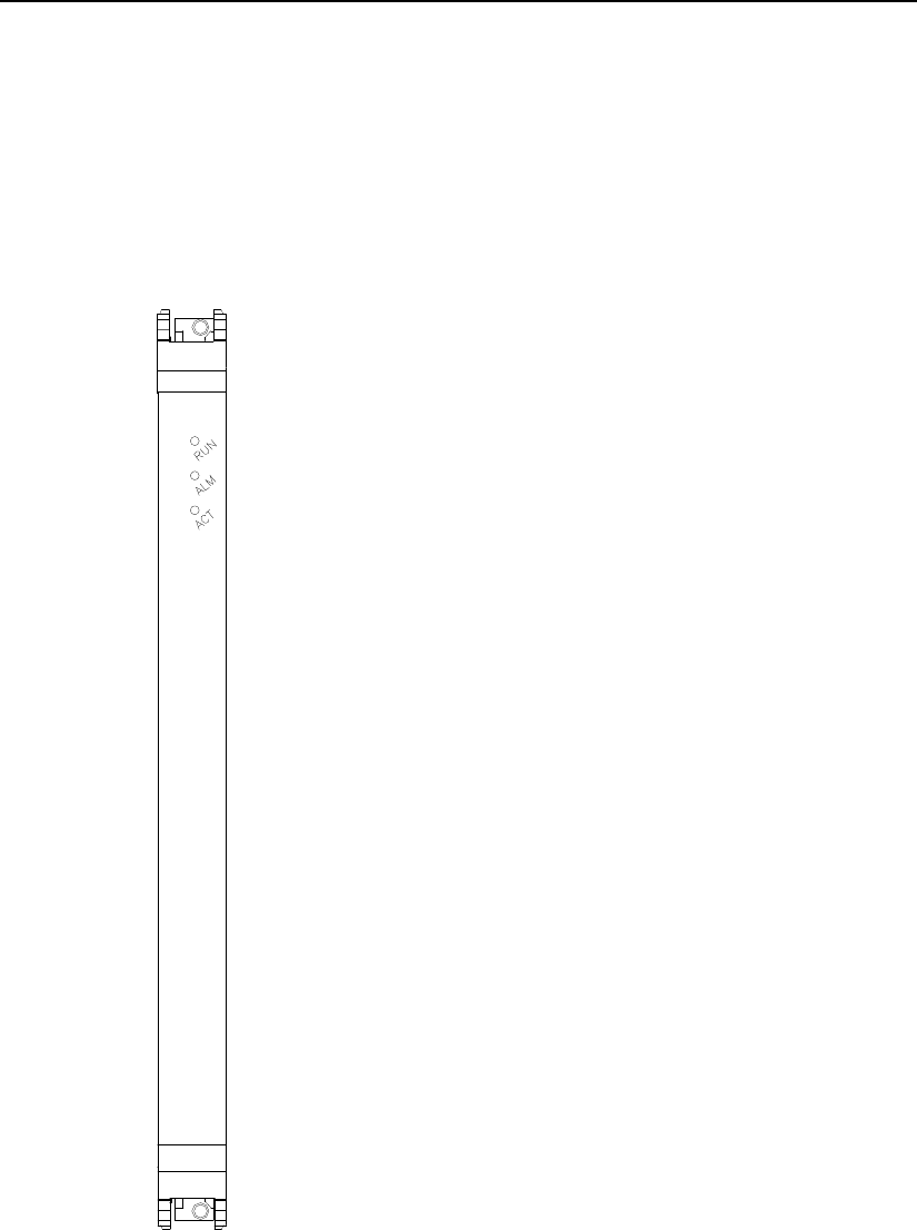
User Manual
Airbridge cBTS3612-800 12-carrier CDMA Base Station 1
BTS Control Interface Module (BCIM)
03Q-0112-20020720-120 1-1
1 BTS Control Interface Module (BCIM)
1.1 BCIM Indicators
BCIM indicators are shown in Figure 1-1.
Figure 1-1 BCIM panel
See Table 1-1 for the description of BCIM indicators.
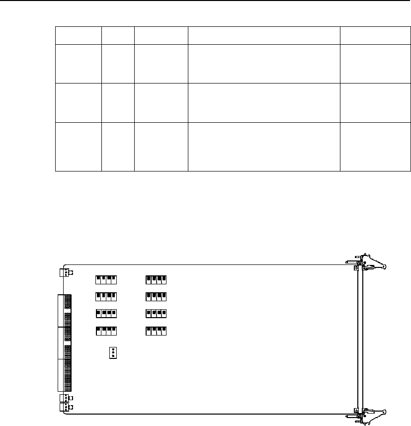
User Manual
Airbridge cBTS3612-800 12-carrier CDMA Base Station 1
BTS Control Interface Module (BCIM)
03Q-0112-20020720-120 1-2
Table 1-1 BCIM indicators
Indicator Color Function Details Normal status
RUN Green Status
Indicator
Quick flash (4Hz): BCIM is being powered on
and initialized or is downloading software.
Slow flash (0.5Hz): BCIM is running normally.
Others: BCIM is faulty.
Slow flash
(0.5Hz)
ALM Red Alarm
indicator
Quick flash (4Hz): Critical alarm.
Slow flash (0.5Hz): Major alarm.
Slow flash (0.25Hz): Minor alarm.
Off: No alarm.
Off
ACT Green Operation
indicator
On: BCIM is running normally.
Quick flash (4Hz): Operation & maintenance
link is faulty.
Slow flash (0.5Hz): IMA group is interrupted.
Slow flash (0.25Hz): IMA link is broken.
On
1.2 BCIM DIP Switches and Jumpers
BCIM DIP switches and jumpers are shown in Figure 1-2.
S5
ON
1 2 3
S3
ON
1 2 3
S9
ON
1 2 3
S7
ON
1 2 3
S4
ON
1 2 3
S2
ON
1 2 3
S8
ON
1 2 3
S6
ON
1 2 3
J6 1 2
Figure 1-2 BCIM DIP switches and jumpers

User Manual
Airbridge cBTS3612-800 12-carrier CDMA Base Station 1
BTS Control Interface Module (BCIM)
03Q-0112-20020720-120 1-3
See Table 1-2 for the description of BCIM DIP switches and jumpers.
Table 1-2 BCIM DIP switches and jumpers
Sequence
number Function Description
S2~S9
Selection of: 1) E1 interface matching
impedance (75W/120W); 2) E1
interface unbalanced/unbalanced
mode.
All four digits set to OFF: 120W twisted pairs.
All four digits set to ON: 75W co-axial cable, with sheath
connected with PGND.
Digits 1 and 2 set to ON, and digits 3 and 4 set to OFF:
75W co-axial cable, with sheath not connected with
PGND.
Other settings: Undefined.
J6
Feedback of E1 interface matching
impedance (75W120W) mode. The
program initializes E1 driving chip
based on the status of this jumper.
Connect jumpers 2 and 3: 120W configuration mode.
Connect the others or no connection at all:
75W configuration mode
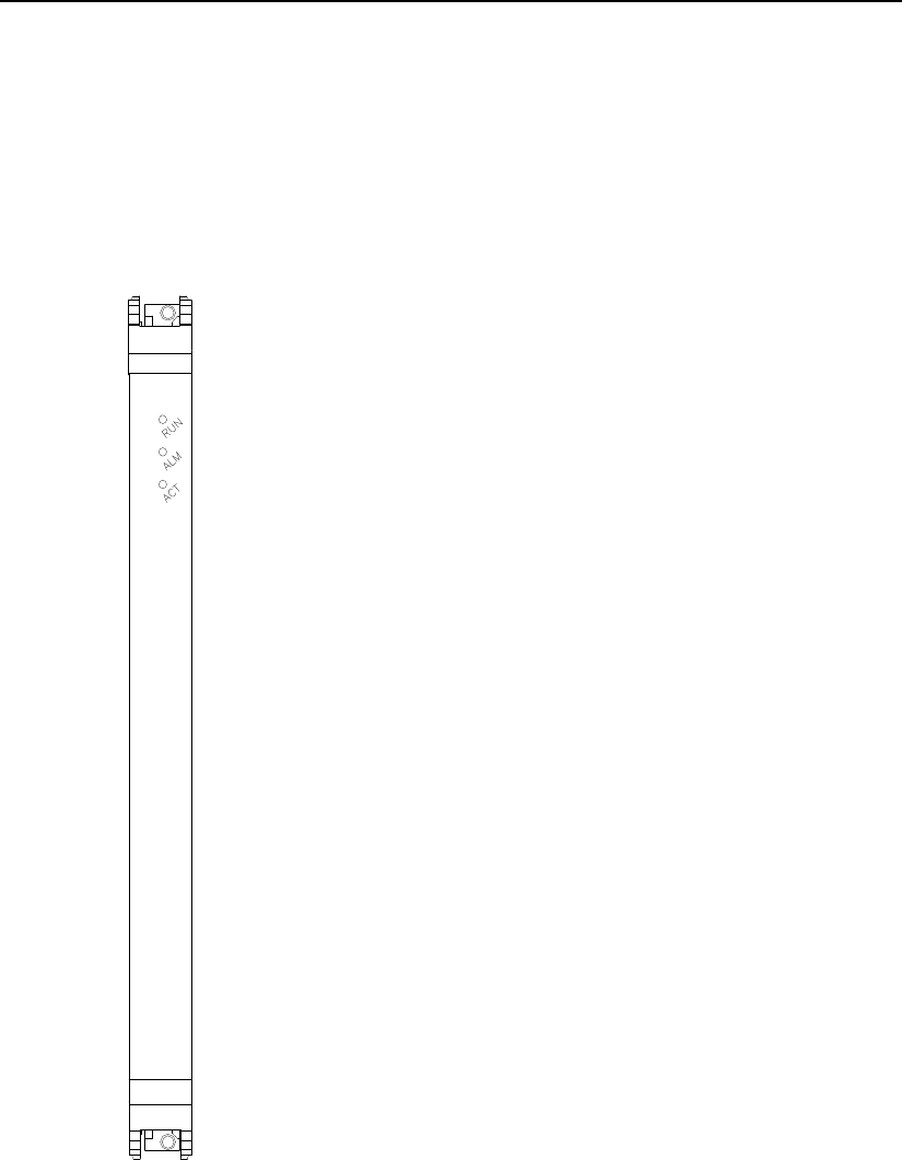
User Manual
Airbridge cBTS3612-800 12-carrier CDMA Base Station 2 BTS Channel Processing Module (BCPM)
03Q-0112-20020720-120 2-1
2 BTS Channel Processing Module (BCPM)
2.1 BCPM Indicators
BCPM indicators are shown in Figure 2-1.
Figure 2-1 BCPM panel

User Manual
Airbridge cBTS3612-800 12-carrier CDMA Base Station 2 BTS Channel Processing Module (BCPM)
03Q-0112-20020720-120 2-2
See Table 2-1 for the description of BCPM indicators.
Table 2-1 BCPM indicators
Indicator Color Function Details Normal
status
RUN Green Status
Indicator
Quick flash (4Hz): BCPM is being powered on and
initialized or is downloading software.
Slow flash (0.5Hz): BCPM is running normally.
Others: BCPM is faulty.
Slow flash
(0.5Hz)
ALM Red Alarm indicator
Quick flash (4Hz): Critical alarm.
Slow flash (0.5Hz): Major alarm.
Slow flash (0.25Hz): Minor alarm.
Off: No alarm.
Off
ACT Green Operation
indicator
On: BCPM is running normally.
Quick flash (4Hz): T8206 alarm.
Slow flash (0.5Hz): Signaling Link disconnected.
Slow flash (0.25Hz): CSM5000 alarm.
On
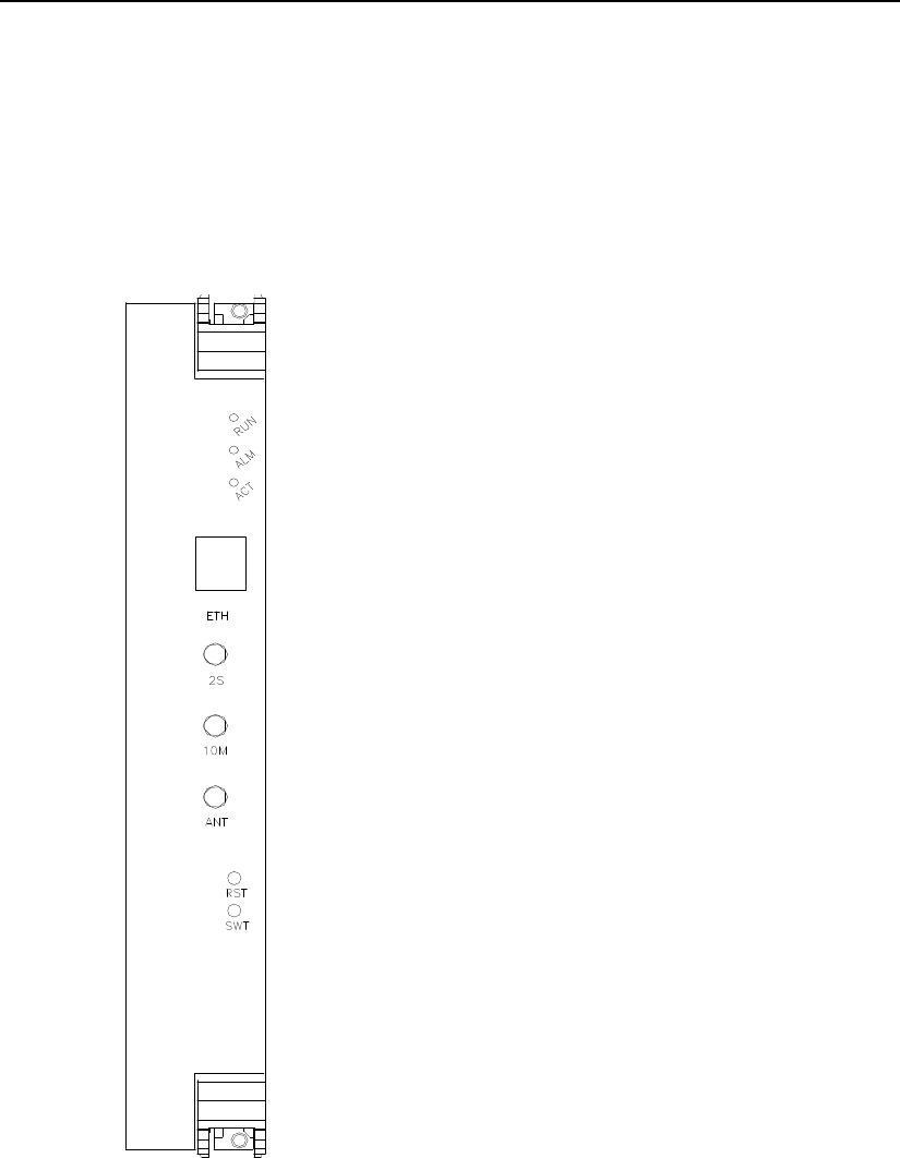
User Manual
Airbridge cBTS3612-800 12-carrier CDMA Base Station 3
BTS ClocK Module (BCKM)
03Q-0112-20020720-120 3-1
3 BTS ClocK Module (BCKM)
3.1 BCKM Indicators
BCKM indicators are shown in Figure 3-2.
Figure 3-2 BCKM panel

User Manual
Airbridge cBTS3612-800 12-carrier CDMA Base Station 3
BTS ClocK Module (BCKM)
03Q-0112-20020720-120 3-2
See Table 3-1 for the description of BCKM indicators.
Table 3-1 BCKM indicators
Indicator Color Function Details Normal
status
RUN Green Status
Indicator
Quick flash (4Hz): BCKM is being powered on and
initialized or is downloading software.
Slow flash (0.5Hz): BCKM is running normally.
Others: BCKM is faulty.
Slow flash
(0.5Hz)
ALM Red Alarm indicator
Quick flash (4Hz): Critical alarm.
Slow flash (0.5Hz): Major alarm.
Slow flash (0.25Hz): Minor alarm.
Off: No alarm.
Off
ACT Green Operation
indicator
On BCKM is running normally.
Quick flash (4Hz): Operation & maintenance link is
faulty.
Slow flash (0.5Hz): BSC link is interrupted.
Slow flash (0.25Hz): 1) Satellite signal has been lost
for 24 hours, 2) No satellite is detected when the
BCKM is powered on for the first time.
On
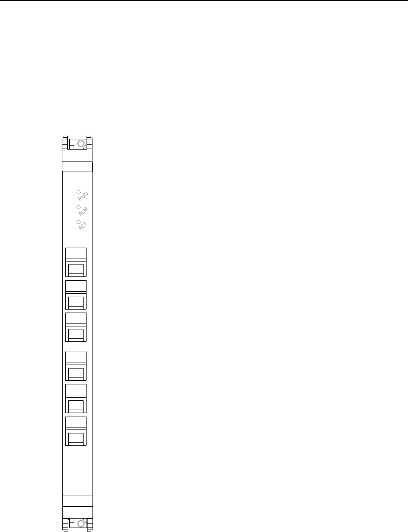
User Manual
Airbridge cBTS3612-800 12-carrier CDMA Base Station 4 BTS Resource Distribution Module (BRDM)
03Q-0112-20020720-120 4-1
4 BTS Resource Distribution Module (BRDM)
4.1 BRDM Indicators
BRDM indicators are shown in Figure 4-1.
0
1
2
3
4
5
Figure 4-1 BRDM panel

User Manual
Airbridge cBTS3612-800 12-carrier CDMA Base Station 4 BTS Resource Distribution Module (BRDM)
03Q-0112-20020720-120 4-2
See Table 4-1 for the description of BRDM indicators.
Table 4-1 BRDM indicators
Indicator Color Function Details Normal
status
RUN Green Status
Indicator
Quick flash (4Hz): BRDM is being powered on and
initialized or is downloading software.
Slow flash (0.5Hz): BRDM runs normally.
Others: BRDM fault.
Slow flash
(0.5Hz)
ALM Red Alarm
indicator
Quick flash (4Hz): Critical alarm.
Slow flash (0.5Hz): Major alarm.
Slow flash (0.25Hz): Minor alarm.
Off: No alarm.
Off
ACT Green Operation
indicator
On: BRDM is running normally.
Quick flash (4Hz): T8206 alarm.
Slow flash (0.5Hz): FPGA alarm.
Slow flash (0.25Hz): QMC trunk alarm.
On
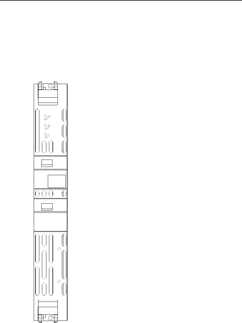
User Manual
Airbridge cBTS3612-800 12-carrier CDMA Base Station 5
BTS TransceiveR Module (BTRM)
03Q-0112-20020720-120 5-1
5 BTS TransceiveR Module (BTRM)
5.1 Board Indicators
BTRM indicators are shown in Figure 5-1.
Figure 5-1 BTRM panel

User Manual
Airbridge cBTS3612-800 12-carrier CDMA Base Station 5
BTS TransceiveR Module (BTRM)
03Q-0112-20020720-120 5-2
See Table 5-1 for the description of BTRM indicators.
Table 5-1 BTRM indicators
Indicator Color Function Details Normal
status
RUN Green Status Indicator
Quick flash (4Hz): BTRM is being powered on and
initialized or is downloading software.
Slow flash (0.5Hz): BTRM is running normally.
Others: BTRM is faulty.
Slow flash
(0.5Hz)
ALM Red Alarm indicator
Quick flash (4Hz): Critical alarm.
Slow flash (0.5Hz): Major alarm.
Slow flash (0.25Hz): Minor alarm.
Off: No alarm.
Off
ACT Green Operation
indicator
On: BTRM is running normally, and the clock has
been locked.
Slow flash (0.5Hz): 1) The clock has not been locked;
2) The clock cannot be locked.
On
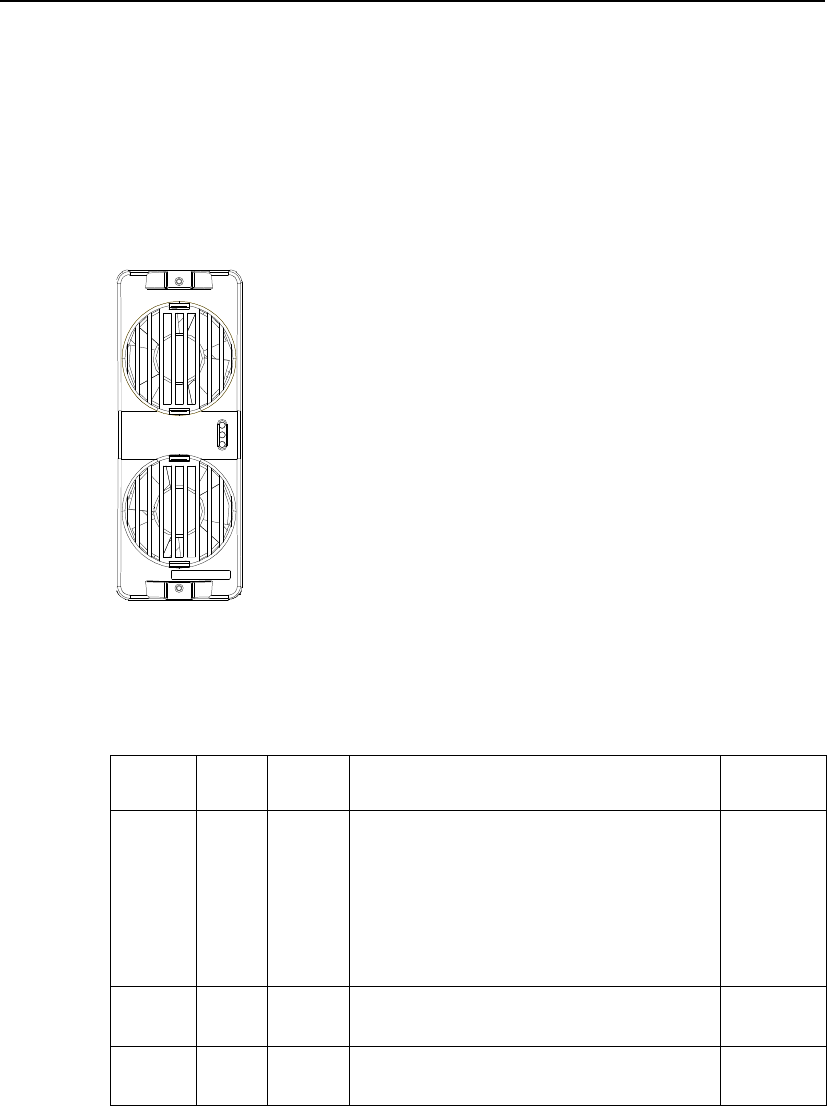
User Manual
Airbridge cBTS3612-800 12-carrier CDMA Base Station 6
BTS RF Fan Module (BRFM)
03Q-0112-20020720-120 6-1
6 BTS RF Fan Module (BRFM)
6.1 BRFM Indicators
BRFM indicators are shown in Figure 6-1.
Figure 6-1 BTS RF Fan Module
See Table 6-1for the description of BRFM indicators.
Table 6-1 BRFM indicators
Indicator Color Function Details Normal
status
TRX Green BTRM
alarm
indicator
On: BTRM is in running normally.
Quick flash (4Hz): BTRM is not in service or with critical
alarm.
Slow flash (0.5Hz): BTRM is in service, but with major
alarm.
Slow flash (0.25Hz): BTRM is in service, but with minor
alarm.
Off: the communication between BTRM and the fan
monitor board is interrupted.
On
HPA Green HPA
Status
indicator
On: HPA is running normally.
Quick flash (4Hz): HPA alarm. On
FAN Green Fan
Status
indicator
On: The fan is running normally.
Quick flash (4Hz): The fan is unable to rotate. On
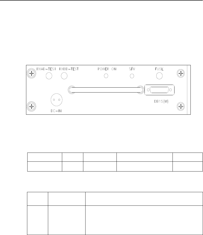
User Manual
Airbridge cBTS3612-800 12-carrier CDMA Base Station 7 Receiving Line Division Unit (RLDU)
03Q-0112-20020720-120 7-1
7 Receiving Line Division Unit (RLDU)
7.1 RLDU Indicators and DIP Switches
RLDU indicators and DIP switches are shown in Table 7-1.
Table 7-1 RLDU panel
See Table 7-1 and Table 7-2 for the descriptions of RLDU indicators and RLDU DIP
switch settings.
Table 7-1 RLDU indicator description
Indicator Color Function Details Normal status
POWER Green Power indicator On: normal.
Off: abnormal. On
Table 7-2 RLDU DIP switches
DIP
Switch Details Description
S/W
Number of sector
carriers
corresponding to
RLDU
S/W set as 0: 1) Number of sectors of the BTS 3, 2 number of carriers for
each sector 4.
2) There are 2 carriers in each sector and the interval between carriers in
each sector is not equal to CDU
S/W set as 1: the carriers in each sector are =2 and each sector is
configured with one CDU.
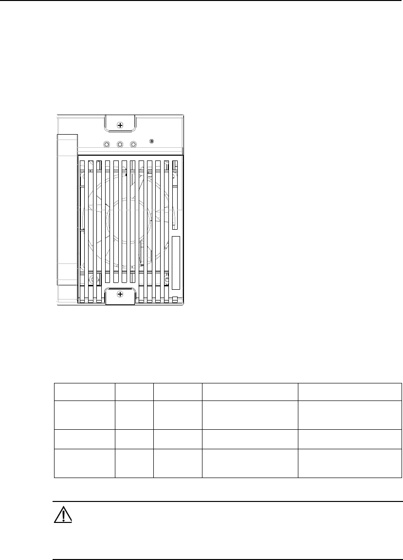
User Manual
Airbridge cBTS3612-800 12-carrier CDMA Base Station 8 Power Supply Unit (PSU)
03Q-0112-20020720-120 8-1
8 Power Supply Unit (PSU)
8.1 PSU Indicators
PSU indicators are shown in Figure 8-1.
Vin Vo
Alm
Figure 8-1 PSU panel
See Table 8-1 for the description of PSU indicators.
Table 8-1 PSU indicators
Indicator Color Function Details Normal status
Vin Green Power input
status
indicator
On: normal.
Off: abnormal. On
Alm Red Module fault
indicator On: alarm.
Off: normal. Off
Vo Green Power
output
indicator
On: normal.
Off: abnormal. On
Caution:
Possible cause to module fault alarm: Input power under/over voltage, over-heated or the power supply
unit is not well plugged in.

User Manual
Airbridge cBTS3612-800 12-carrier CDMA Base Station 8 Power Supply Unit (PSU)
03Q-0112-20020720-120 9-1
9 BTS Lightning Protection Indicator Board (BPLI)
9.1 BPLI Indicator
BPLI indicators are shown in .Figure 9-1
RUN L-alm
Figure 9-1 BPLI panel
See Table 9-1for the description of BPLI indicators.
Table 9-1 BPLI indicators
Indicator Color Meaning Details Normal status
RUN Green -48V Power
indicator On: -48V power input is normal.
On: -48V power input is abnormal. On
L-alm Red Lightening
protector
indicator
On: Lightning protector abnormal.
Off: Lightning protector normal. Off
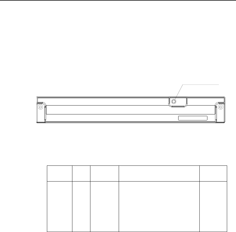
User Manual
Airbridge cBTS3612-800 12-carrier CDMA Base Station 8 Power Supply Unit (PSU)
03Q-0112-20020720-120 10-1
10 BTS Fan Monitor Module (BFMM)
10.1 BFMM Indicators
BFMM indicators are shown in Figure 10-1.
BFMM indicator
Figure 10-1 Fan box panel
See Table 10-1 for the description of BFMM indicators.
Table 10-1 BFMM indicator
Indicator Color Meaning Details Normal
status
BFMM
Indicators Green Operational
status
indicator
Fast flashing (4Hz): fault has occurred to
the monitored objects, such as: 1) fan
unable to rotate; 2) port communication
abnormal; 3) mono-stable circuit fault.
Slow flashing (0.5Hz): the fan monitoring
circuits and the monitored object are
working normally.
On or Off: The controlling chip on the fan
monitoring board is down.
Slow flash
(0.5Hz)