Huawei Technologies DRH3926A Distributed Remote Head User Manual II
Huawei Technologies Co.,Ltd Distributed Remote Head II
Contents
- 1. User Manual
- 2. User Manual II
- 3. User Manual III
User Manual II

DRH
Installation Guide
Issue
Draft A
Date
2013-04-26
HUAWEI TECHNOLOGIES CO., LTD.

Issue Draft A ()
Huawei Proprietary and Confidential
Copyright © Huawei Technologies Co., Ltd..
i
Copyright © Huawei Technologies Co., Ltd. 2013. All rights reserved.
No part of this document may be reproduced or transmitted in any form or by any means without prior
written consent of Huawei Technologies Co., Ltd.
Trademarks and Permissions
and other Huawei trademarks are trademarks of Huawei Technologies Co., Ltd.
All other trademarks and trade names mentioned in this document are the property of their respective
holders.
Notice
The purchased products, services and features are stipulated by the contract made between Huawei and
the customer. All or part of the products, services and features described in this document may not be
within the purchase scope or the usage scope. Unless otherwise specified in the contract, all statements,
information, and recommendations in this document are provided "AS IS" without warranties, guarantees or
representations of any kind, either express or implied.
The information in this document is subject to change without notice. Every effort has been made in the
preparation of this document to ensure accuracy of the contents, but all statements, information, and
recommendations in this document do not constitute the warranty of any kind, express or implied.
Huawei Technologies Co., Ltd.
Address:
Huawei Industrial Base
Bantian, Longgang
Shenzhen 518129
People's Republic of China
Website:
http://www.huawei.com
Email:
support@huawei.com

DRH
Installation Guide
About This Chapter
Issue Draft A ()
Huawei Proprietary and Confidential
Copyright © Huawei Technologies Co., Ltd..
iii
About This Chapter
Purpose
This document describes the process of installing a DC DRH (referred to as DRH in this
document). (DRH:Distributed Remote Head)
Product Versions
The following table lists the product versions related to this document.
Product Name
Product Version
DRH
V100R001 and later versions
Intended Audience
This document is intended for:
Base station installation engineers
Organization
1 Changes in the DRH Installation Guide
This chapter describes the changes in the DRH Installation Guide.
2 Installation Preparations
This chapter describes the reference documents, tools, and instruments that must be ready
before the installation. In addition, it specifies the skills and prerequisites that installation
engineers must have.
3 Information About the Installation
Before installing a DRH, you must be familiar with its exterior, ports, indicators, installation
options and installation clearance requirements.
4 Unpacking the Equipment
This chapter describes how to unpack and check the delivered equipment to ensure that all the
materials are included and intact.
5 Installation Process

DRH
Installation Guide
About This Chapter
Issue Draft A ()
Huawei Proprietary and Confidential
Copyright © Huawei Technologies Co., Ltd..
iv
The installation process involves installing a DRH and DRH cables, checking the DRH
hardware installation, and powering on the DRH.
6 (Optional) Installing the Plastic Shells of the DRH
This section describes the procedure for installing the plastic shells of the DRH.
8 Installing the DRH
This chapter describes the procedure for installing the DRH. The DRH can be installed on a
pole, U-steel, angle steel, wall, or an IFS06 . The procedure for installing the DRH varies
depending on installation options.
9 Installing DRH Cables
This chapter describes the procedure for installing DRH cables.
10 Checking the DRH Hardware Installation
After a DRH is installed, check the hardware installation.
11 Powering On a DRH
After all the devices are installed, check the power-on status of a DRH.
12 Appendix
This section describes the procedure for adding an easy power receptacle (pressfit type)
connector.

DRH
Installation Guide
Contents
Issue Draft A ()
Huawei Proprietary and Confidential
Copyright © Huawei Technologies Co., Ltd..
v
Contents
1 Changes in the DRH Installation Guide ............................................................................... 1
2 Installation Preparations ......................................................................................................... 2
2.1 Reference Documents ................................................................................................................................ 2
2.2 Tools and Instruments ................................................................................................................................ 2
2.3 Skills and Requirements for Onsite Personnel ............................................................................................ 4
3 Information About the Installation ....................................................................................... 5
3.1 DRH Exterior ............................................................................................................................................ 5
3.2 DRH Ports ................................................................................................................................................. 6
3.3 DRH Indicators ......................................................................................................................................... 8
3.4 Installation Scenarios ................................................................................................................................. 9
3.5 Installation Clearance Requirements of a DRH ..........................................................................................18
4 Unpacking the Equipment .................................................................................................... 27
5 Installation Process ................................................................................................................ 29
6 (Optional) Installing the Plastic Shells of the DRH .......................................................... 30
7 Installing the DRH ................................................................................................................. 33
7.1 Mounting Kits for a DRH .........................................................................................................................33
7.2 Installing the DRH on a Pole .....................................................................................................................35
7.3 Installing the DRH on U-steel ...................................................................................................................47
7.4 Installing the DRH on Angle Steel ............................................................................................................52
7.5 Installing the DRH on a Wall ....................................................................................................................57
7.6 Installing a DRH on an IFS06 ...................................................................................................................64
8 Installing DRH Cables .......................................................................................................... 72
8.1 Cabling Requirements...............................................................................................................................73
8.2 Cable Connections ....................................................................................................................................76
8.3 Installation Process ...................................................................................................................................77
8.4 DRH Cable List ........................................................................................................................................78
8.5 Installing a DRH PGND Cable..................................................................................................................79
8.6 Installing a DRH RF Jumper .....................................................................................................................80
8.7 Installing a DRH Alarm Cable ..................................................................................................................84
8.8 Opening the Cover Plate of a DRH Cabling Cavity....................................................................................85
8.9 Installing a DRH Power Cable ..................................................................................................................86
8.10 Installing a CPRI Fiber Optic Cable ........................................................................................................88

DRH
Installation Guide
Contents
Issue Draft A ()
Huawei Proprietary and Confidential
Copyright © Huawei Technologies Co., Ltd..
vi
8.11 Closing the Cover Plate of a DRH Cabling Cavity ...................................................................................91
9 Checking the DRH Hardware Installation ......................................................................... 93
10 Powering On a DRH ............................................................................................................ 94
11 Appendix ............................................................................................................................... 97
11.1 Adding a Tool-Less Female Connector (Pressfit Type) to the DRH Power Cable on the DRH Side ...........97

DRH
Installation Guide
1 Changes in the DRH Installation Guide
Issue Draft A ()
Huawei Proprietary and Confidential
Copyright © Huawei Technologies Co., Ltd..
1
1 Changes in the DRH Installation Guide
This chapter describes the changes in the DRH Installation Guide.
01 (2013-04-26)
This is the first official release.
DRH
Installation Guide
2 Installation Preparations
Issue Draft A ()
Huawei Proprietary and Confidential
Copyright © Huawei Technologies Co., Ltd..
2
2 Installation Preparations
This chapter describes the reference documents, tools, and instruments that must be ready
before the installation. In addition, it specifies the skills and prerequisites that installation
engineers must have.
2.1 Reference Documents
Before the installation, you must be familiar with reference documents.
2.2 Tools and Instruments
You must prepare the following tools and instruments before the installation.
2.3 Skills and Requirements for Onsite Personnel
Onsite personnel must be qualified and trained. Before performing any operation, onsite
personnel must be familiar with correct operation methods and safety precautions.
2.1 Reference Documents
Before the installation, you must be familiar with reference documents.
The following reference documents are required during DRH installation:
DRH Hardware Description
DRH Installation Guide
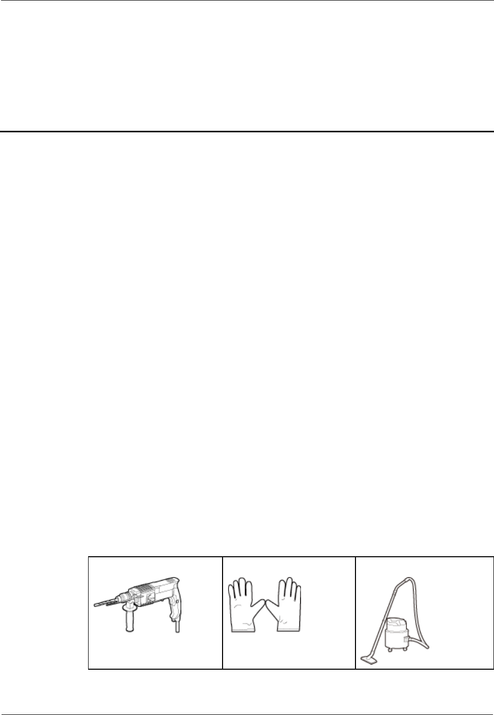
2.2 Tools and Instruments
You must prepare the following tools and instruments before the installation.
Hammer drill (a φ12 bit)
ESD gloves
Vacuum cleaner
DRH
Installation Guide
2 Installation Preparations
Issue Draft A ()
Huawei Proprietary and Confidential
Copyright © Huawei Technologies Co., Ltd..
3
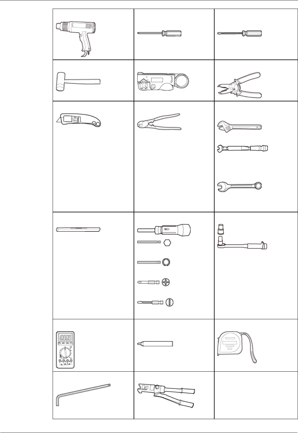
Heat gun
Phillips screwdriver (M3 to
M6)
Flat-head screwdriver (M3 to
M6)
Rubber mallet
COAX crimping tool
Wire stripper
Utility knife
Cable cutter
Adjustable wrench (size ≥ 32
mm [1.26 in.])
Torque wrench
Size: 16 mm (0.63 in.) and
32 mm (1.26 in.)
Combination wrench
Size: 16 mm (0.63 in.) and
32 mm (1.26 in.)
Level
Torque screwdriver
5 mm
5mm
(M3 to M6)
(M3 to M6)
Torque socket
Multimeter
Marker (diameter ≤ 10 mm
[0.39 in.])
Measuring tape
Inner hexagon wrench
5 mm
Hydraulic pliers

DRH
Installation Guide
2 Installation Preparations
Issue Draft A ()
Huawei Proprietary and Confidential
Copyright © Huawei Technologies Co., Ltd..
4
2.3 Skills and Requirements for Onsite Personnel
Onsite personnel must be qualified and trained. Before performing any operation, onsite
personnel must be familiar with correct operation methods and safety precautions.
Before the installation, pay attention to the following items:
The customer's technical engineers must be trained by Huawei and be familiar with the
proper installation and operation methods.
The number of onsite personnel depends on the engineering schedule and installation
environment. Generally, only three to five onsite personnel are necessary.

DRH
Installation Guide
3 Information About the Installation
Issue Draft A ()
Huawei Proprietary and Confidential
Copyright © Huawei Technologies Co., Ltd..
5
3 Information About the Installation
Before installing a DRH, you must be familiar with its exterior, ports, indicators, installation
options and installation clearance requirements.
3.1 DRH Exterior
This section describes the exterior and dimensions of a DRH.
3.2 DRH Ports
This section describes ports on the DRH panels. A DRH has a bottom panel, cabling cavity
panel, and indicator panel.
3.3 DRH Indicators
This section describes six indicators on a DRH. They indicate the running status.
3.4 Installation Scenarios
A DRH can be installed on a pole, U-steel, angle steel, wall, or IFS06. Installation scenarios
must meet heat-dissipation and waterproofing requirements of the DRH.
3.5 Installation Clearance Requirements of a DRH
This section describes the requirements for the installation clearance of a single DRH and
multiple DRHs and the requirements for the installation spacing between DRHs.
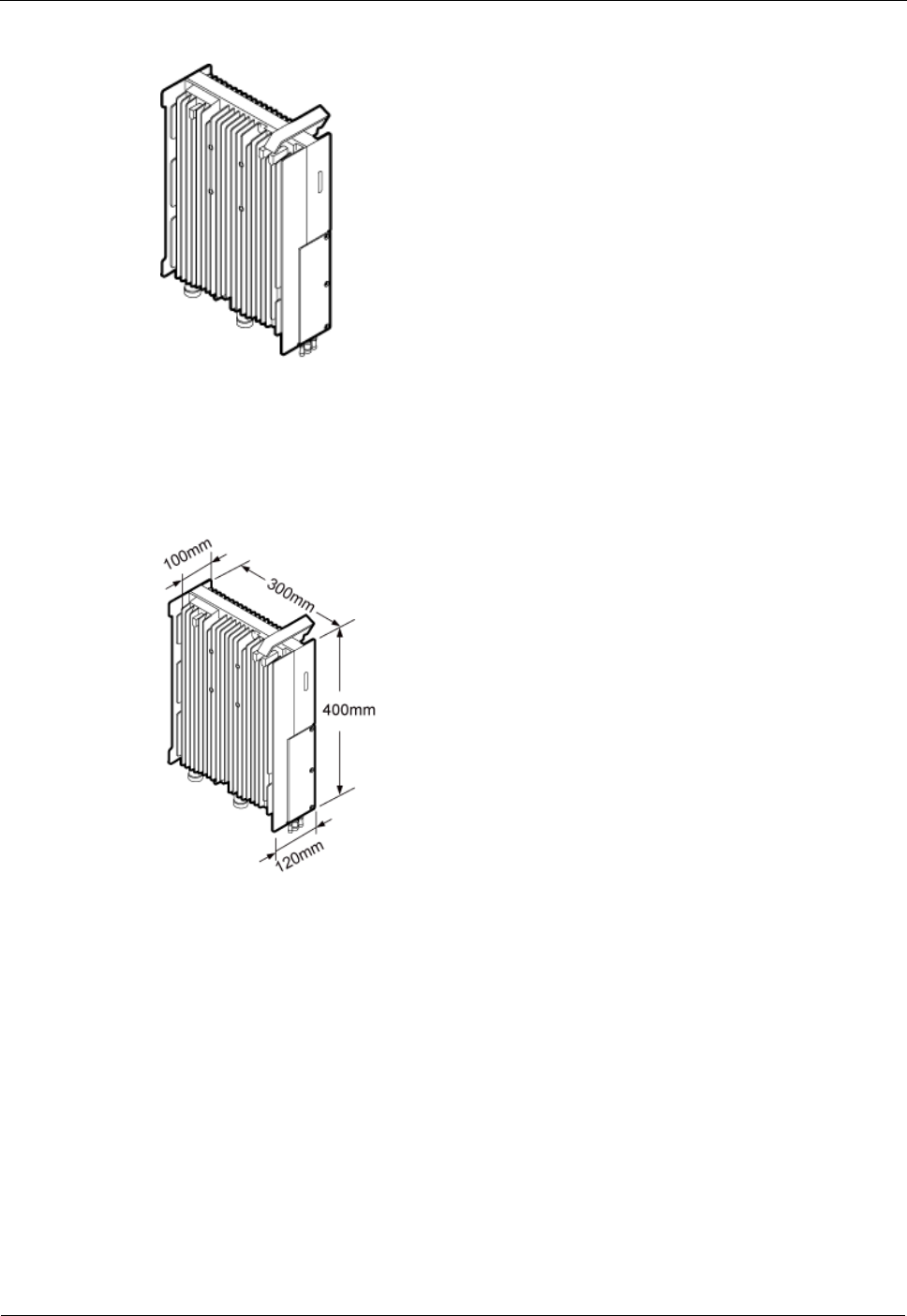
3.1 DRH Exterior
This section describes the exterior and dimensions of a DRH.
Figure 3-1 shows a DRH.
DRH
Installation Guide
3 Information About the Installation
Issue Draft A ()
Huawei Proprietary and Confidential
Copyright © Huawei Technologies Co., Ltd..
6
Figure 3-1 DRH exterior
Figure 3-2 shows DRH dimensions.
Figure 3-2 DRH dimensions
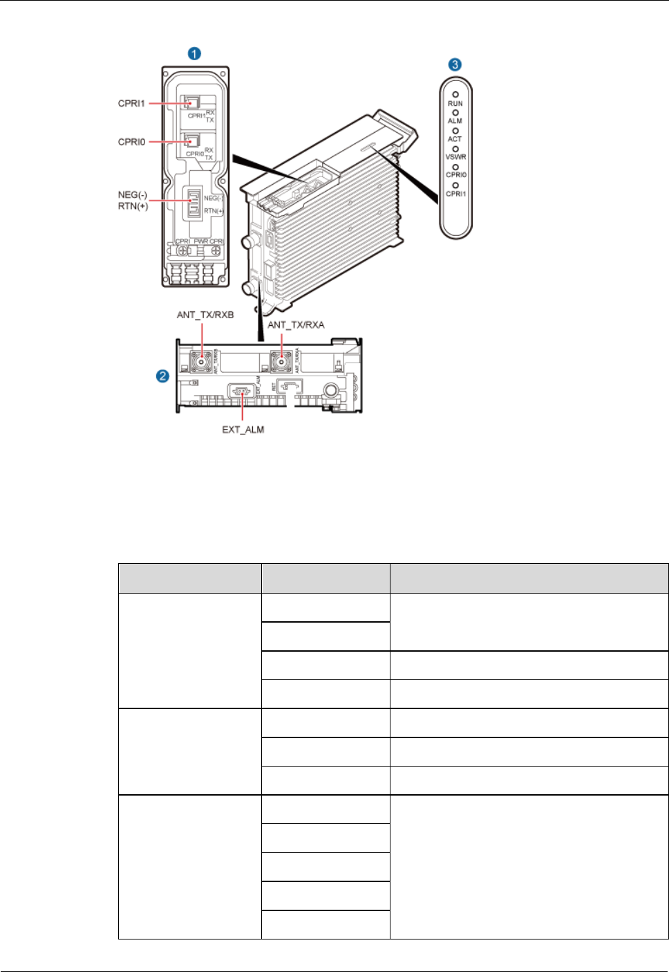
3.2 DRH Ports
This section describes ports on the DRH panels. A DRH has a bottom panel, cabling cavity
panel, and indicator panel.
Figure 3-3 shows the ports on the DRH panels.
DRH
Installation Guide
3 Information About the Installation
Issue Draft A ()
Huawei Proprietary and Confidential
Copyright © Huawei Technologies Co., Ltd..
7
Figure 3-3 Ports on the DRH panels
Table 3-1 describes ports and indicators on the DRH panels.
Table 3-1 Ports and indicators on the DRH panels
Item
Silkscreen
Remarks
(1) Ports in the
cabling cavity
RTN(+)
Power supply socket
NEG(-)
CPRI0
Optical/electrical port 0
CPRI1
Optical/electrical port 1
(2) Ports at the
bottom
ANT_TX/RXA
TX/RX port A
ANT_RXB
RX port B
EXT_ALM
Alarm port
(3) Indicators
RUN
See 3.3 DRH Indicators.
ALM
ACT
VSWR
CPRI0

DRH
Installation Guide
3 Information About the Installation
Issue Draft A ()
Huawei Proprietary and Confidential
Copyright © Huawei Technologies Co., Ltd..
8
Item
Silkscreen
Remarks
CPRI1
The port for transmitting RET signals is determined by the software.
3.3 DRH Indicators
This section describes six indicators on a DRH. They indicate the running status.
For detailed positions of DRH indicators, see 3.2 DRH Ports.
Table 3-2 describes DRH indicators.
Table 3-2 DRH indicators
Indicator
Color
Status
Meaning
RUN
Green
Steady on
There is power supply, but the module is
faulty.
Steady off
There is no power supply, or the module is
faulty.
Blinking (on for
1s and off for 1s)
The board is functioning properly.
Blinking (on for
0.125s and off for
0.125s)
Software is being loaded to the module, or
the module is not started.
ALM
Red
Steady on
Alarms are generated, and the module must
be replaced.
Blinking (on for
1s and off for 1s)
Alarms are generated. The alarms may be
caused by the faults on the related boards or
ports. Therefore, you need to locate the
fault before deciding whether to replace the
module.
Steady off
No alarm is generated.
ACT
Green
Steady on
The module is running properly with TX
channels enabled or the software is being
loaded without DRH running.
Blinking (on for
1s and off for 1s)
The module is running properly with TX
channels disabled.
VSWR
Red
Steady off
No Voltage Standing Wave Ratio (VSWR)
alarm is generated.
Blinking (on for
1s and off for 1s)
VSWR alarms are generated on the
ANT_RXB port.

DRH
Installation Guide
3 Information About the Installation
Issue Draft A ()
Huawei Proprietary and Confidential
Copyright © Huawei Technologies Co., Ltd..
9
Indicator
Color
Status
Meaning
Steady on
VSWR alarms are generated on the
ANT_TX/RXA port.
Blinking (on for
0.125s and off for
0.125s)
VSWR alarms are generated on the
ANT_TX/RXA and ANT_ RXB ports.
CPRI0
Red or
green
Steady green
The CPRI link is functioning properly.
Steady red
An optical module fails to transmit or
receive signals because the optical module
is faulty or the fiber optic cable is broken.
Blinking red (on
for 1s and off for
1s)
The CPRI link is out of lock because of a
failure in clock lock between two modes or
mismatched data rates over CPRI ports.
Steady off
The optical module cannot be detected, or
the optical module is powered off.
CPRI1
Red or
green
Steady green
The CPRI link is functioning properly.
Steady red
An optical module fails to transmit or
receive signals because the optical module
is faulty or the fiber optic cable is broken.
Blinking red (on
for 1s and off for
1s)
The CPRI link is out of lock because of a
failure in clock lock between two modes or
mismatched data rates over CPRI ports.
Steady off
The optical module cannot be detected, or
the optical module is powered off.
3.4 Installation Scenarios
A DRH can be installed on a pole, U-steel, angle steel, wall, or IFS06. Installation scenarios
must meet heat-dissipation and waterproofing requirements of the DRH.
Requirements for the Installation Scenarios
Application scenarios:
To ensure proper heat dissipation of the DRH, the following requirements must be met:
The DRH cannot be installed in an enclosed cabinet without a cooling system.
The DRH cannot be installed in an enclosed camouflage box.
The DRH cannot be installed in an enclosed equipment room without a cooling system.
When multiple DRHs are installed in centralized mode, the minimum clearance
requirements must be met. For details about the minimum clearance requirements, see
Clearances for Three or More DRHs and Installation Spacing Between DRHs.
DRH
Installation Guide
3 Information About the Installation
Issue Draft A ()
Huawei Proprietary and Confidential
Copyright © Huawei Technologies Co., Ltd..
10
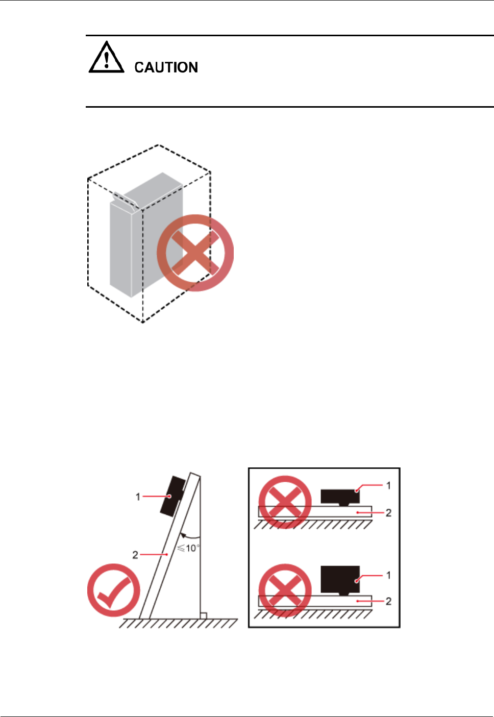
If the DRH is improperly installed, heat dissipation of the DRH deteriorates and the DRH
may not work properly, as shown in Figure 3-4.
Figure 3-4 Improperly installed DRHs
Method of installation:
To ensure the heat dissipation of the DRH and waterproofing of the ports at the bottom
of the DRH, the vertical deviation angle of a DRH must be less than or equal to 10
degrees, as shown in Figure 3-5.
Figure 3-5 Requirements for the vertical deviation angle of a DRH
(1) DRH
(2) Installation support (pole, U-steel, angle steel, or wall)
DRH
Installation Guide
3 Information About the Installation
Issue Draft A ()
Huawei Proprietary and Confidential
Copyright © Huawei Technologies Co., Ltd..
11
Installing a DRH on a Pole
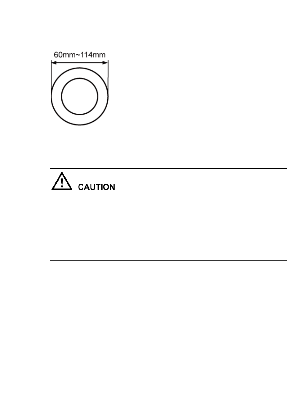
Figure 3-6 shows the diameter of a pole for installing a DRH.
Figure 3-6 Diameter of a pole
The diameter of a pole for installing a DRH ranges from 60 mm (2.36 in.) to 114 mm (4.49
in.). The recommended diameter is 80 mm (3.15 in.).
When the diameter of a pole ranges from 60 mm (2.36 in.) to 76 mm (2.99 in.), a
maximum of three DRHs can be installed on the pole and the side-mounted installation is
recommended.
Only a pole whose diameter ranges from 76 mm (2.99 in.) to 114 mm (4.49 in.) supports
more than three DRHs.
The recommended thickness of the wall of a pole is 3.5 mm (0.14 in.) or above.
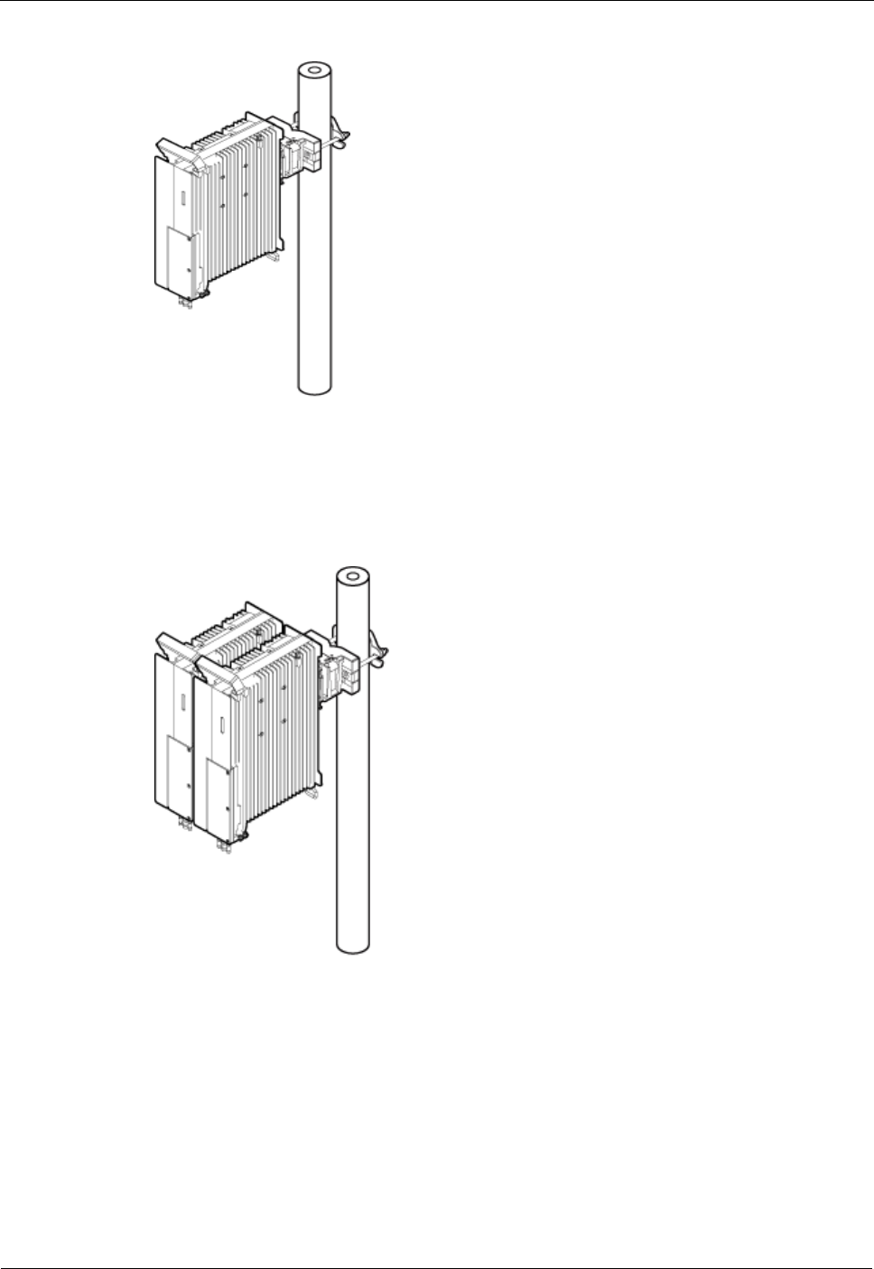
Figure 3-7 shows a single DRH installed on a pole.
DRH
Installation Guide
3 Information About the Installation
Issue Draft A ()
Huawei Proprietary and Confidential
Copyright © Huawei Technologies Co., Ltd..
12
Figure 3-7 A single DRH installed on a pole
Figure 3-8 shows two DRHs installed on a pole.
Figure 3-8 Two DRHs installed on a pole
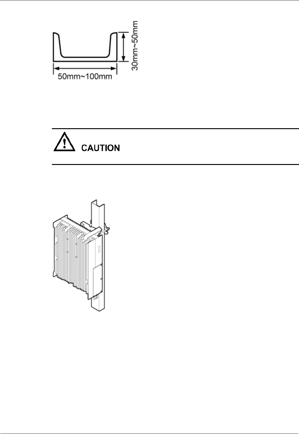
Installing a DRH on U-steel
Figure 3-9 shows U-steel specifications.
DRH
Installation Guide
3 Information About the Installation
Issue Draft A ()
Huawei Proprietary and Confidential
Copyright © Huawei Technologies Co., Ltd..
13
Figure 3-9 U-steel specifications
U-steel supports the standard or reverse installation of a single DRH only.
Figure 3-10 shows a DRH installed on U-steel.
Figure 3-10 DRH installed on U-steel
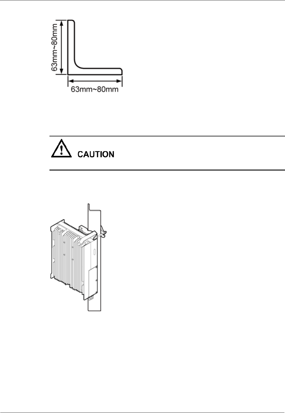
Installing a DRH on Angle Steel
Figure 3-11 shows angle steel specifications.
DRH
Installation Guide
3 Information About the Installation
Issue Draft A ()
Huawei Proprietary and Confidential
Copyright © Huawei Technologies Co., Ltd..
14
Figure 3-11 Angle steel specifications
Angle steel supports the standard or reverse installation of a single DRH only.
Figure 3-12 shows a DRH installed on angle steel.
Figure 3-12 DRH installed on angle steel
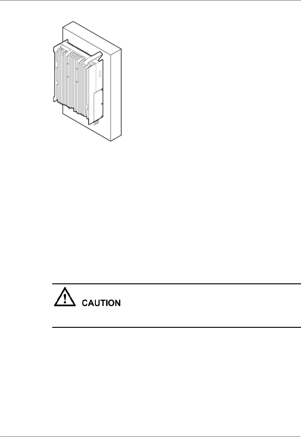
Installing a DRH on a Wall
The wall for installing DRHs must meet the following requirements:
When a single DRH is installed, the wall has a capacity of bearing at least four times the
weight of the DRH.
Expansion anchor bolts must be tightened to 30 N·m (265.52 lbf·in.) so that the bolts
stay secured without damaging the wall.
DRH
Installation Guide
3 Information About the Installation
Issue Draft A ()
Huawei Proprietary and Confidential
Copyright © Huawei Technologies Co., Ltd..
15
It is recommended that the DRH be installed on a wall in standard mode.
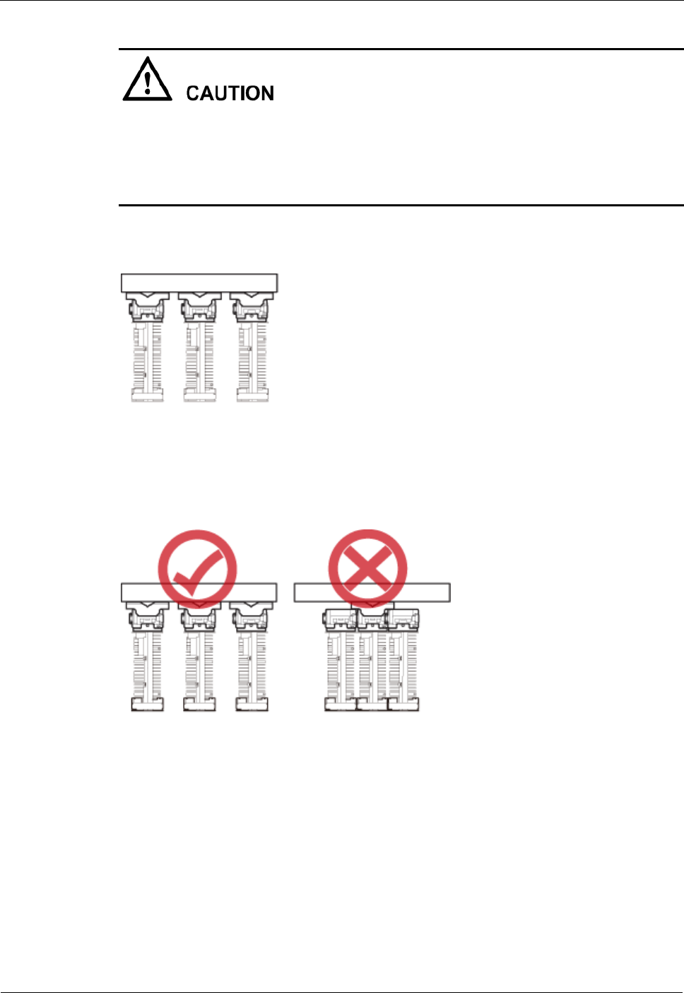
When DRHs are installed on a wall outdoors in side-mounted mode, you are not advised to
combine the mounting brackets for multiple DRHs, as shown in Figure 3-13. When DRHs
are installed on a wall indoors in side-mounted mode, do not combine mounting brackets
for multiple DRHs, as shown in Figure 3-14.
Figure 3-13 Correct installation of mounting brackets for multiple DRHs installed on an outdoor
wall in side-mounted mode
Figure 3-14 Correct installation of mounting brackets for multiple DRHs installed on an indoor
wall in side-mounted mode
Figure 3-15 shows a DRH installed on a wall.
DRH
Installation Guide
3 Information About the Installation
Issue Draft A ()
Huawei Proprietary and Confidential
Copyright © Huawei Technologies Co., Ltd..
16
Figure 3-15 DRH installed on a wall
Installing a DRH on an IFS06
In an IFS06 scenario:
The upper and lower adjustable beams on an IFS06 can be moved up and down to fit for
heights of DRHs.
The IFS06 supports at least three DRHs when the ambient temperature is higher than or
equal to the lowest operating temperature of the DRH and at least 5°C (41°F) lower than
the highest operating temperature of the DRH. The IFS06 supports a maximum of six
DRHs when the ambient temperature is higher than or equal to the lowest operating
temperature of the DRH and at least 10°C (50°F) lower than the highest operating
temperature of the DRH.
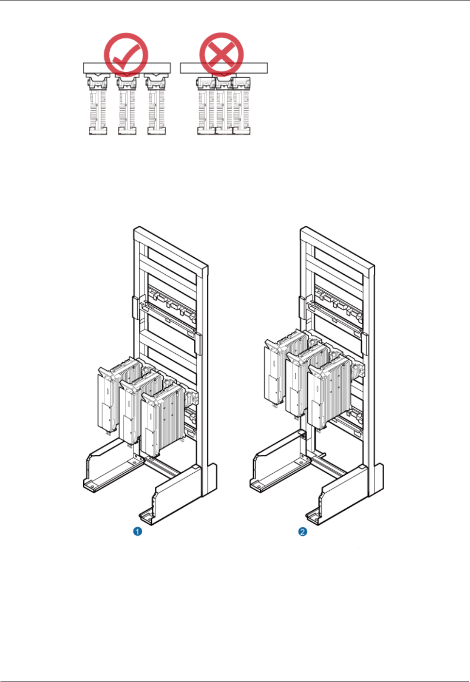
The mounting brackets for multiple DRHs cannot be combined when the DRHs are installed
on an IFS06, as shown in Figure 3-16.
DRH
Installation Guide
3 Information About the Installation
Issue Draft A ()
Huawei Proprietary and Confidential
Copyright © Huawei Technologies Co., Ltd..
17
Figure 3-16 Correct installation of mounting brackets for DRHs installed on an IFS06
Figure 3-17 and Figure 3-18 show DRHs installed on an IFS06.
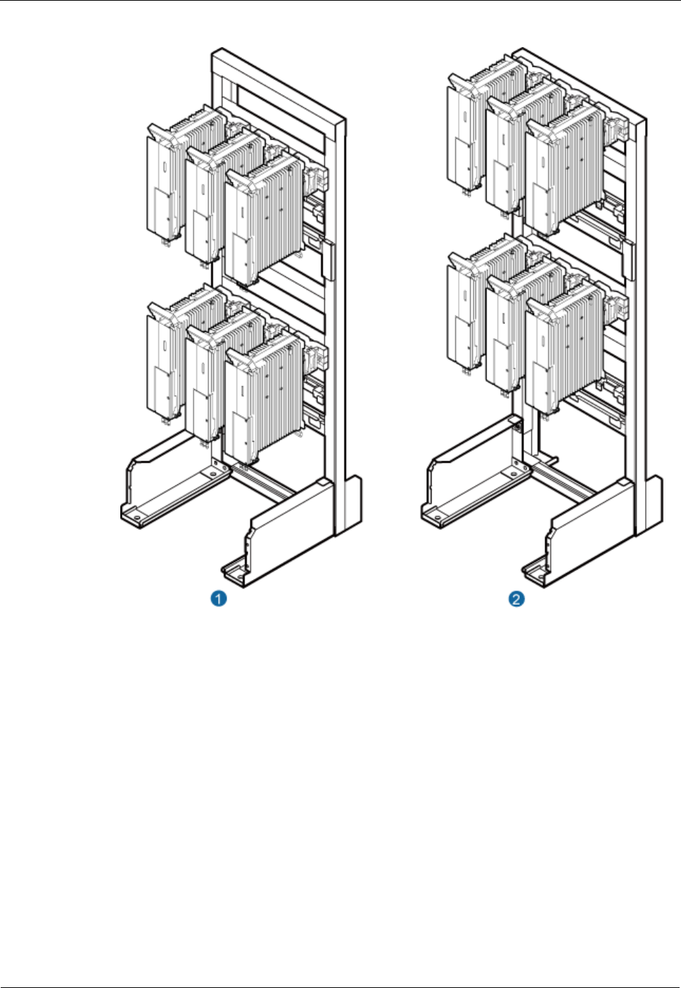
Figure 3-17 Three DRHs installed on an IFS06
(1) Height-restricted scenario
(2) Height-unrestricted scenario
DRH
Installation Guide
3 Information About the Installation
Issue Draft A ()
Huawei Proprietary and Confidential
Copyright © Huawei Technologies Co., Ltd..
18
Figure 3-18 Six DRHs installed on an IFS06
(1) Height-restricted scenario
(2) Height-unrestricted scenario
3.5 Installation Clearance Requirements of a DRH
This section describes the requirements for the installation clearance of a single DRH and
multiple DRHs and the requirements for the installation spacing between DRHs.
Clearance for a Single DRH
This section describes the recommended and minimum clearance for a single DRH.
DRH
Installation Guide
3 Information About the Installation
Issue Draft A ()
Huawei Proprietary and Confidential
Copyright © Huawei Technologies Co., Ltd..
19
The recommended clearance ensures normal running and provides an appropriate space for
operation and maintenance (OM). If there is sufficient space, leave the recommended clearance after
installing the equipment.
The minimum clearance ensures normal running and heat dissipation, but OM activities such as
checking indicator status and opening the cabling cavity cannot be properly conducted. If the
installation space is restricted, leave the minimum clearance after installing the equipment.
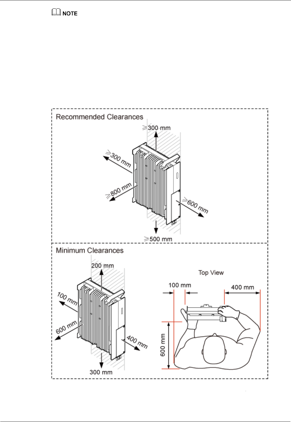
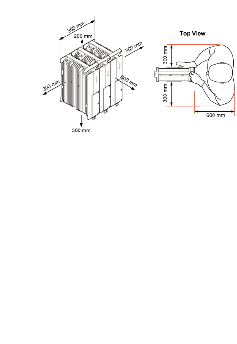
Clearance for a Single DRH in Standard or Reverse Mode
Figure 3-19 shows the clearance for a single DRH in standard or reverse mode.
Figure 3-19 Clearance for a single DRH in standard or reverse mode
DRH
Installation Guide
3 Information About the Installation
Issue Draft A ()
Huawei Proprietary and Confidential
Copyright © Huawei Technologies Co., Ltd..
20
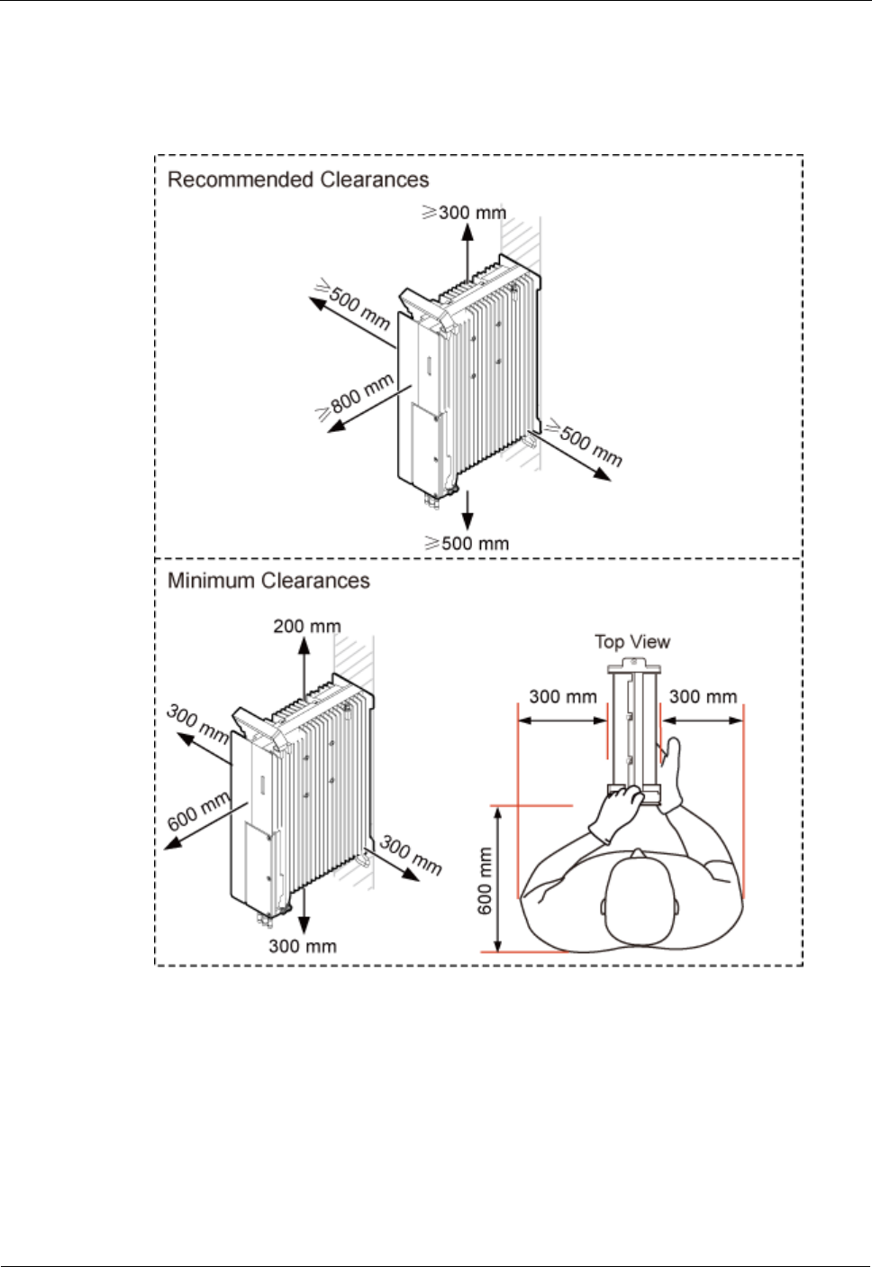
Clearance for a Single DRH in Side-Mounted Mode
Figure 3-20 shows the clearance for a single DRH in side-mounted mode.
Figure 3-20 Clearance for a single DRH in side-mounted mode
Clearances for Three or More DRHs
This section describes the recommended and minimum clearances for three or more DRHs.
DRH
Installation Guide
3 Information About the Installation
Issue Draft A ()
Huawei Proprietary and Confidential
Copyright © Huawei Technologies Co., Ltd..
21
The recommended clearances ensure normal running and provide an appropriate space for operation
and maintenance (OM). If there is sufficient space, retain the recommended clearances.
The minimum clearances ensure normal running and heat dissipation but do not allow OM activities
such as checking indicator status and opening the cabling cavity. If the installation space is
insufficient, retain the minimum clearances after the installation.
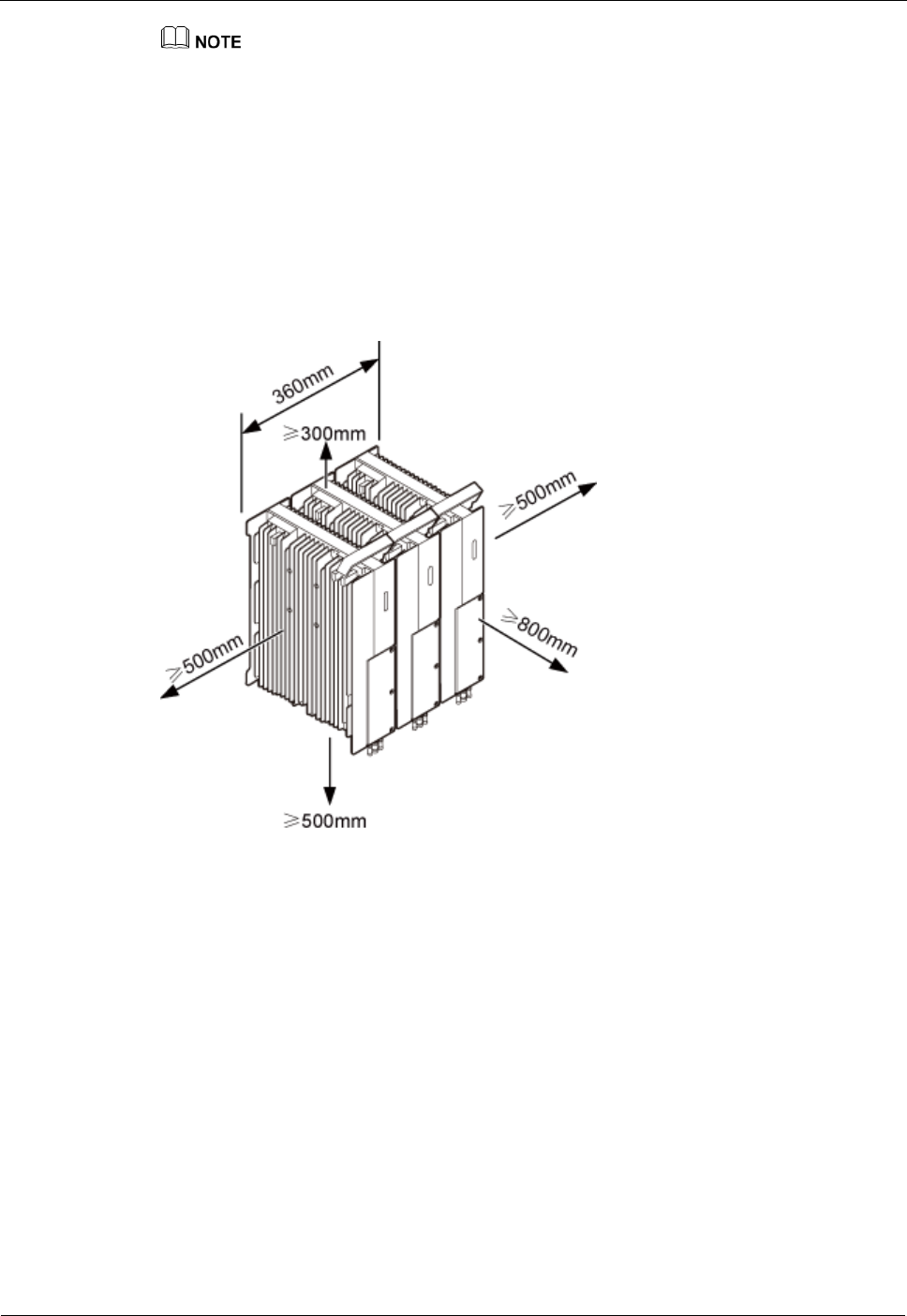
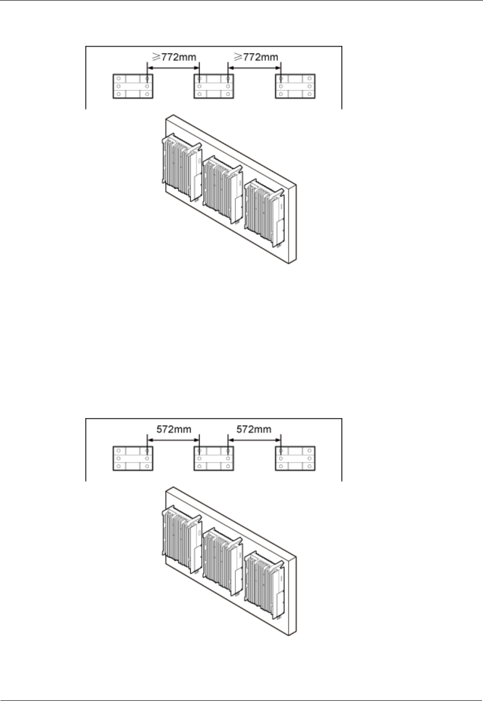
Recommended Clearances for Three or More DRHs Installed on a Pole
Figure 3-21 shows the recommended clearances for multiple DRHs installed in centralized
mode.
Figure 3-21 Recommended clearances for three or more DRHs installed on a pole
Minimum Clearances for Three or More DRHs Installed on a Pole
Figure 3-22 shows the minimum clearances for multiple DRHs installed in centralized mode.
DRH
Installation Guide
3 Information About the Installation
Issue Draft A ()
Huawei Proprietary and Confidential
Copyright © Huawei Technologies Co., Ltd..
22
Figure 3-22 Minimum clearances for multiple DRHs installed in centralized mode
Recommended Clearances for Three or More DRHs Installed on a Wall in
Standard Mode
Figure 3-23 shows the recommended clearances for multiple DRHs installed on a wall in
standard mode.
DRH
Installation Guide
3 Information About the Installation
Issue Draft A ()
Huawei Proprietary and Confidential
Copyright © Huawei Technologies Co., Ltd..
23
Figure 3-23 Recommended clearances for three or more DRHs installed on a wall in standard
mode
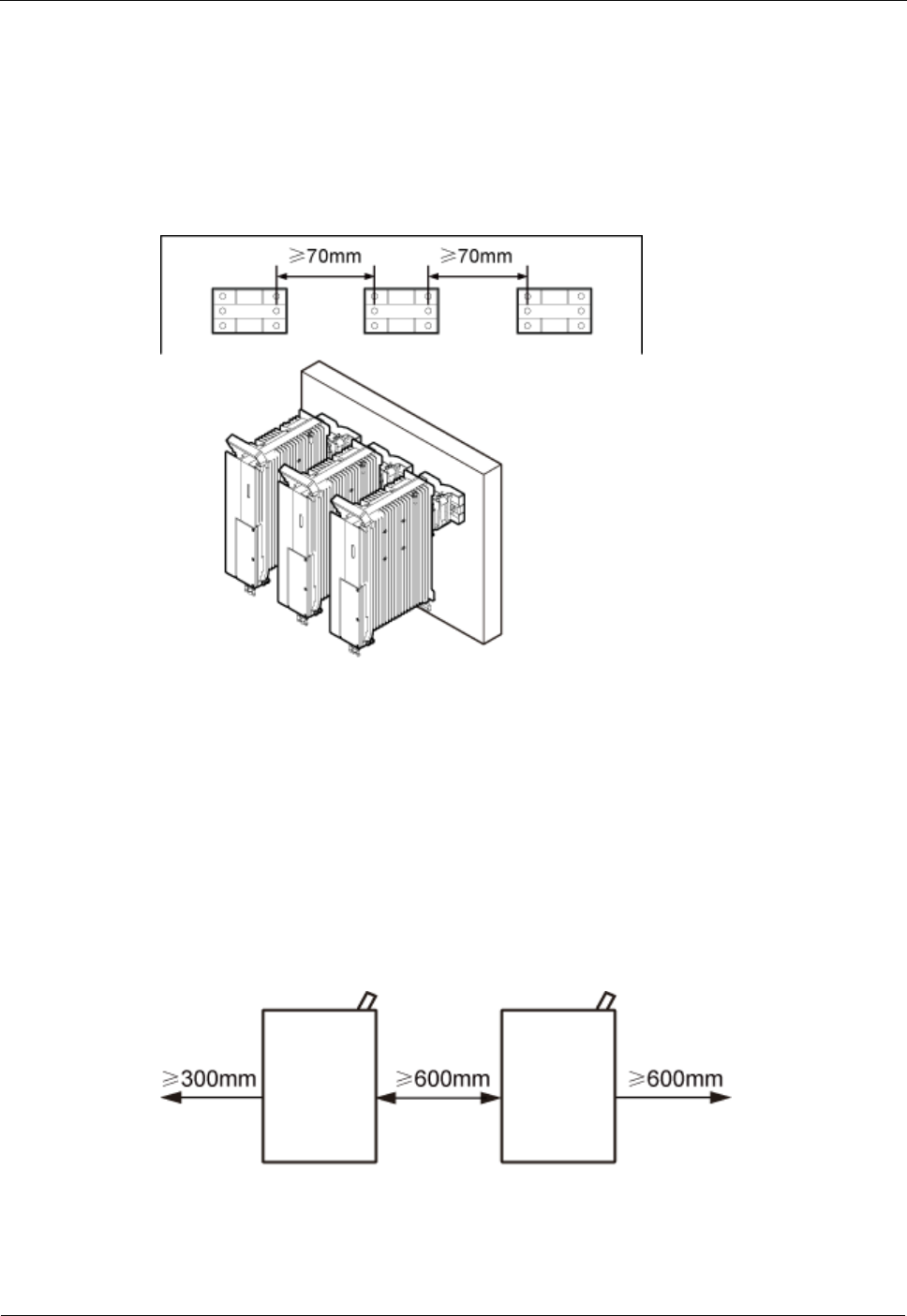
Minimum Clearances for Three or More DRHs Installed on a Wall in Standard
Mode
Figure 3-24 shows the minimum clearances for three or more DRHs installed on a wall in
standard mode.
Figure 3-24 Minimum clearances for three or more DRHs installed on a wall in standard mode
DRH
Installation Guide
3 Information About the Installation
Issue Draft A ()
Huawei Proprietary and Confidential
Copyright © Huawei Technologies Co., Ltd..
24
Recommended Clearances for Three or More DRHs Installed on a Wall in
Side-Mounted Mode
Figure 3-25 shows the recommended clearances for three or more DRHs side-mounted on a
wall.
Figure 3-25 Recommended clearances for three or more DRHs installed on a wall in
side-mounted mode
Installation Spacing Between DRHs
This section describes the horizontal and vertical spacing between DRHs.
Recommended Horizontal Spacing Between DRHs
Figure 3-26 shows the recommended horizontal spacing between DRHs.
Figure 3-26 Recommended horizontal spacing between DRHs
DRH
Installation Guide
3 Information About the Installation
Issue Draft A ()
Huawei Proprietary and Confidential
Copyright © Huawei Technologies Co., Ltd..
25
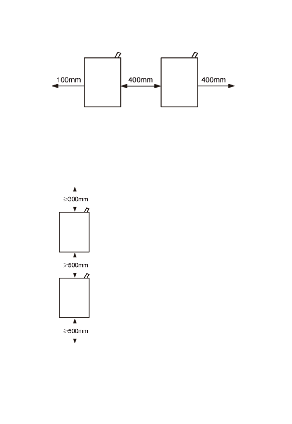
Minimum Horizontal Spacing Between DRHs
Figure 3-27 shows the minimum horizontal spacing between DRHs.
Figure 3-27 Minimum horizontal spacing between DRHs
Recommended Vertical Spacing Between DRHs
Figure 3-28 shows the recommended vertical spacing between DRHs.
Figure 3-28 Recommended vertical spacing between DRHs
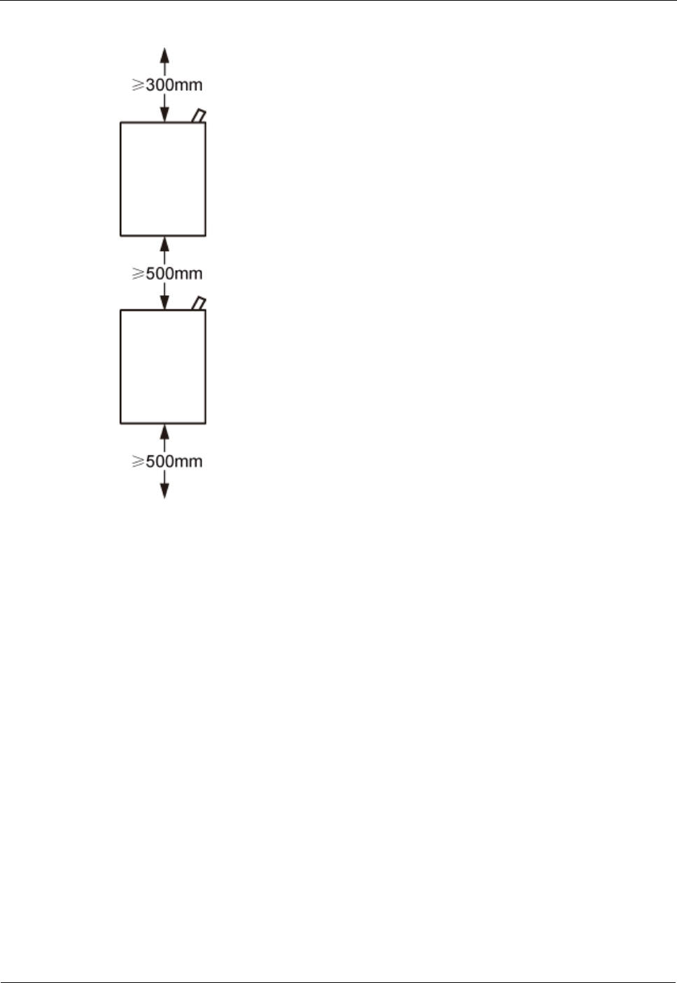
Minimum Vertical Spacing Between DRHs
Figure 3-29 shows the minimum vertical spacing between DRHs.
DRH
Installation Guide
3 Information About the Installation
Issue Draft A ()
Huawei Proprietary and Confidential
Copyright © Huawei Technologies Co., Ltd..
26
Figure 3-29 Minimum vertical spacing between DRHs
DRH
Installation Guide
4 Unpacking the Equipment
Issue Draft A ()
Huawei Proprietary and Confidential
Copyright © Huawei Technologies Co., Ltd..
27
4 Unpacking the Equipment
This chapter describes how to unpack and check the delivered equipment to ensure that all the
materials are included and intact.
Context
When transporting, moving, or installing the equipment, components, or parts, you must:
Prevent them from colliding with doors, walls, shelves, or other objects.
Wear clean gloves, and avoid touching the equipment, components, or parts with bare hands,
sweat-soaked gloves, or dirty gloves.
Procedure
Step 1 Check the total number of articles in each case according to the packing list.
If ...
Then ...
The total number tallies with the
packing list
Go to Step 2.
The total number does not tally with
the packing list
Find out the cause and report any missing articles to
the local Huawei office.
Step 2 Check the exterior of the packing case.
If ...
Then ...
The outer packing is intact
Go to Step 3.
The outer packing is severely
damaged or soaked
Find out the cause and report it to the local Huawei
office.
The shockwatch label is red
Stop unpacking the wooden crate, and then report it to
the transportation company.
Step 3 Check the type and quantity of the equipment in the cases according to the packing list.
If ...
Then ...
Types and quantity of the article tally with those on the
packing list
Sign the Packing List with the
customer.

DRH
Installation Guide
4 Unpacking the Equipment
Issue Draft A ()
Huawei Proprietary and Confidential
Copyright © Huawei Technologies Co., Ltd..
28
If ...
Then ...
Either shipment shortage, wrong shipment or damaged
articles.
Report to the local Huawei office.
To protect the equipment and prevent damage to the equipment, you are advised to keep the
unpacked equipment and packing materials indoors, take photos of the stocking environment,
packing case or carton, packing materials, and any rusted or eroded equipment, and then file
the photos.
----End
DRH
Installation Guide
5 Installation Process
Issue Draft A ()
Huawei Proprietary and Confidential
Copyright © Huawei Technologies Co., Ltd..
29
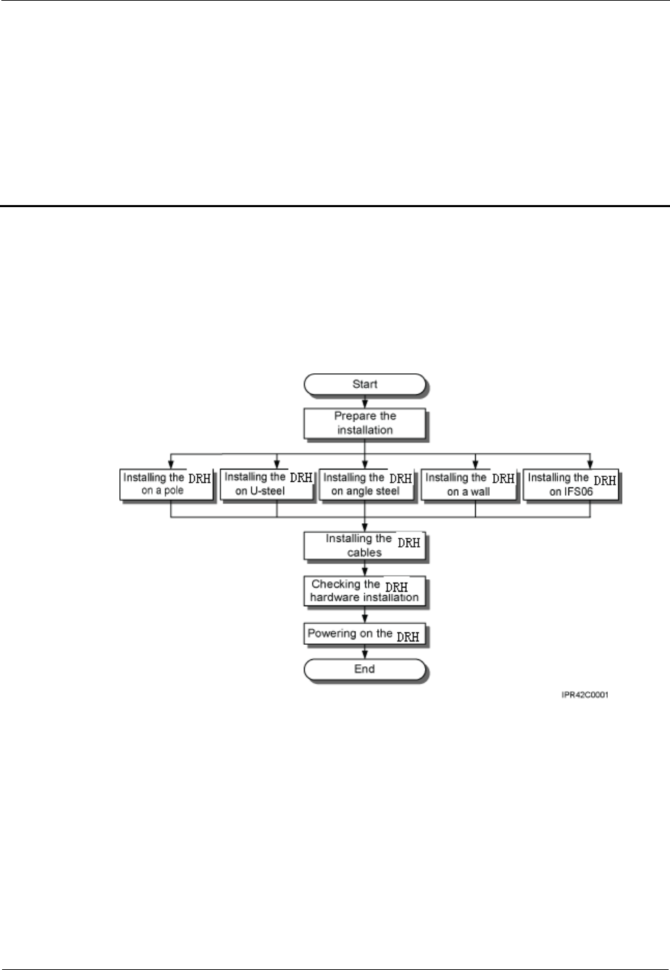
5 Installation Process
The installation process involves installing a DRH and DRH cables, checking the DRH
hardware installation, and powering on the DRH.
Figure 5-1 shows the process of installing a DRH.
Figure 5-1 Process of installing a DRH
DRH
Installation Guide
6 (Optional) Installing the Plastic Shells of the DRH
Issue Draft A ()
Huawei Proprietary and Confidential
Copyright © Huawei Technologies Co., Ltd..
30
6 (Optional) Installing the Plastic Shells of
the DRH
This section describes the procedure for installing the plastic shells of the DRH.
Context
A DRH is equipped with a plastic shell only when necessary.
Procedure
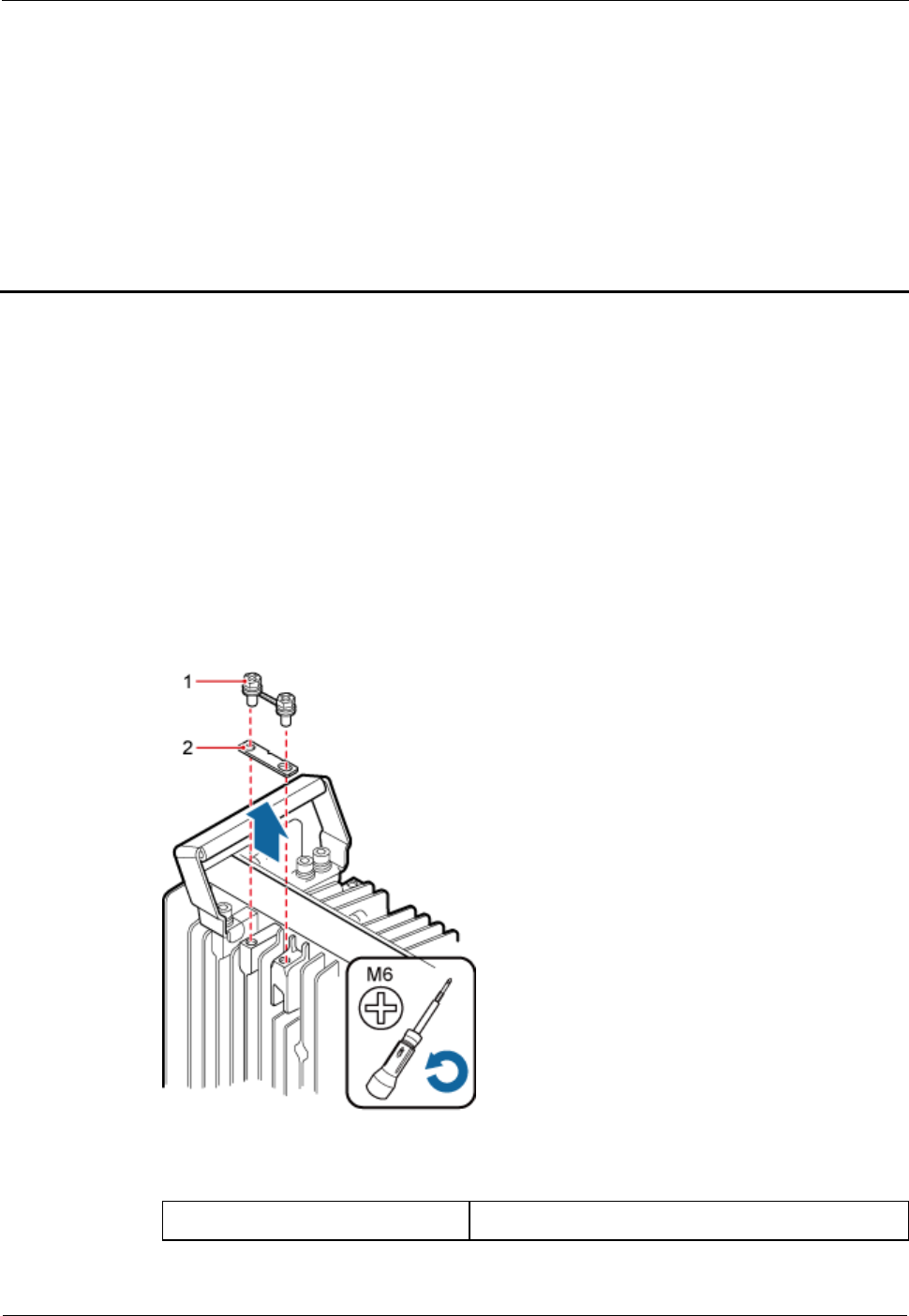
Step 1 Use an M6 Phillips screwdriver to loosen the two screws on the metal sheet of the DRH and
remove the metal sheet, as shown in Figure 6-1.
Figure 6-1 Removing the metal sheet
(1) Screw
(2) Metal sheet

DRH
Installation Guide
6 (Optional) Installing the Plastic Shells of the DRH
Issue Draft A ()
Huawei Proprietary and Confidential
Copyright © Huawei Technologies Co., Ltd..
31
Step 2 Install a buckle on each side at the bottom of the DRH, and use an M4 torque wrench to
tighten the screws on the buckles to 1.4 N•m (12.39 lbf•in.), as shown in Figure 6-2.
Figure 6-2 Installing buckles at the bottom
(1) Buckle
(2) Screw
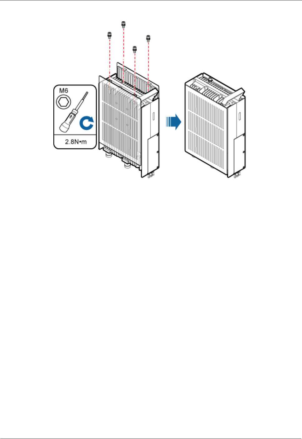
Step 3 Use four hex screws to secure the plastic shells onto the DRH and use an M6 hex key wrench
to tighten the screws to 2.8 N•m (24.78 lbf•in.), as shown in Figure 6-3.
DRH
Installation Guide
6 (Optional) Installing the Plastic Shells of the DRH
Issue Draft A ()
Huawei Proprietary and Confidential
Copyright © Huawei Technologies Co., Ltd..
32
Figure 6-3 Installing the plastic shells of the DRH
----End

DRH
Installation Guide
7 Installing the DRH
Issue Draft A ()
Huawei Proprietary and Confidential
Copyright © Huawei Technologies Co., Ltd..
33
7 Installing the DRH
This chapter describes the procedure for installing the DRH. The DRH can be installed on a
pole, U-steel, angle steel, wall, or an IFS06 . The procedure for installing the DRH varies
depending on installation options.
7.1 Mounting Kits for a DRH
This section describes the bracket assembly and the attachment plate for a DRH.
7.2 Installing the DRH on a Pole
One or more DRHs can be installed on a pole.
7.3 Installing the DRH on U-steel
This section describes the procedure and precautions for installing the DRH on U-steel. A
DRH can be installed on U-steel secured on the ground. Each piece of U-steel allows only one
DRH to be installed in standard or reverse mode.
7.4 Installing the DRH on Angle Steel
This section describes the procedure and precautions for installing the DRH on angle steel. A
DRH can be installed on angle steel secured on the ground. Each piece of angle steel allows
only one DRH to be installed in standard or reverse mode.
7.5 Installing the DRH on a Wall
This section describes the procedure and precautions for installing the DRH on a wall.
7.6 Installing a DRH on an IFS06
This section describes the procedure and precautions for installing a DRH on an IFS06.
7.1 Mounting Kits for a DRH
This section describes the bracket assembly and the attachment plate for a DRH.
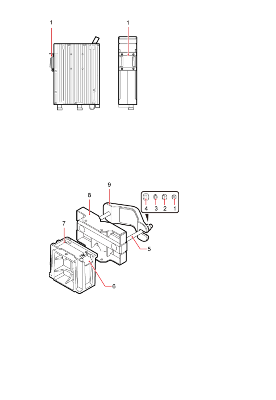
Figure 7-1 shows the front and side of a DRH.
DRH
Installation Guide
7 Installing the DRH
Issue Draft A ()
Huawei Proprietary and Confidential
Copyright © Huawei Technologies Co., Ltd..
34
Figure 7-1 Front and side view of a DRH
(1) Attachment plate
Figure 7-2 shows the bracket assembly for a DRH.
Figure 7-2 12 L blade DRH mounting kit
(1) Plastic cap
(2) Standard
M10 nut
(3) Spring washer
(4) Thick flat
washer
(5)
Square-neck
bolt
(6) Hoist clamp on
the main bracket
(7) Main
bracket
(8) Pole
installation
bracket
(9) Auxiliary
bracket
-
DRH
Installation Guide
7 Installing the DRH
Issue Draft A ()
Huawei Proprietary and Confidential
Copyright © Huawei Technologies Co., Ltd..
35
7.2 Installing the DRH on a Pole
One or more DRHs can be installed on a pole.
Installing a Single DRH
This section describes the procedure and precautions for installing a single DRH on a pole.
Prerequisite
The hoist clamp on the main bracket is secured properly.
Do not stand the DRH upright because the RF ports cannot support the weight of the
DRH.
Place a foam pad or cardboard under the DRH to protect the DRH housing from damage
during the installation.
Procedure
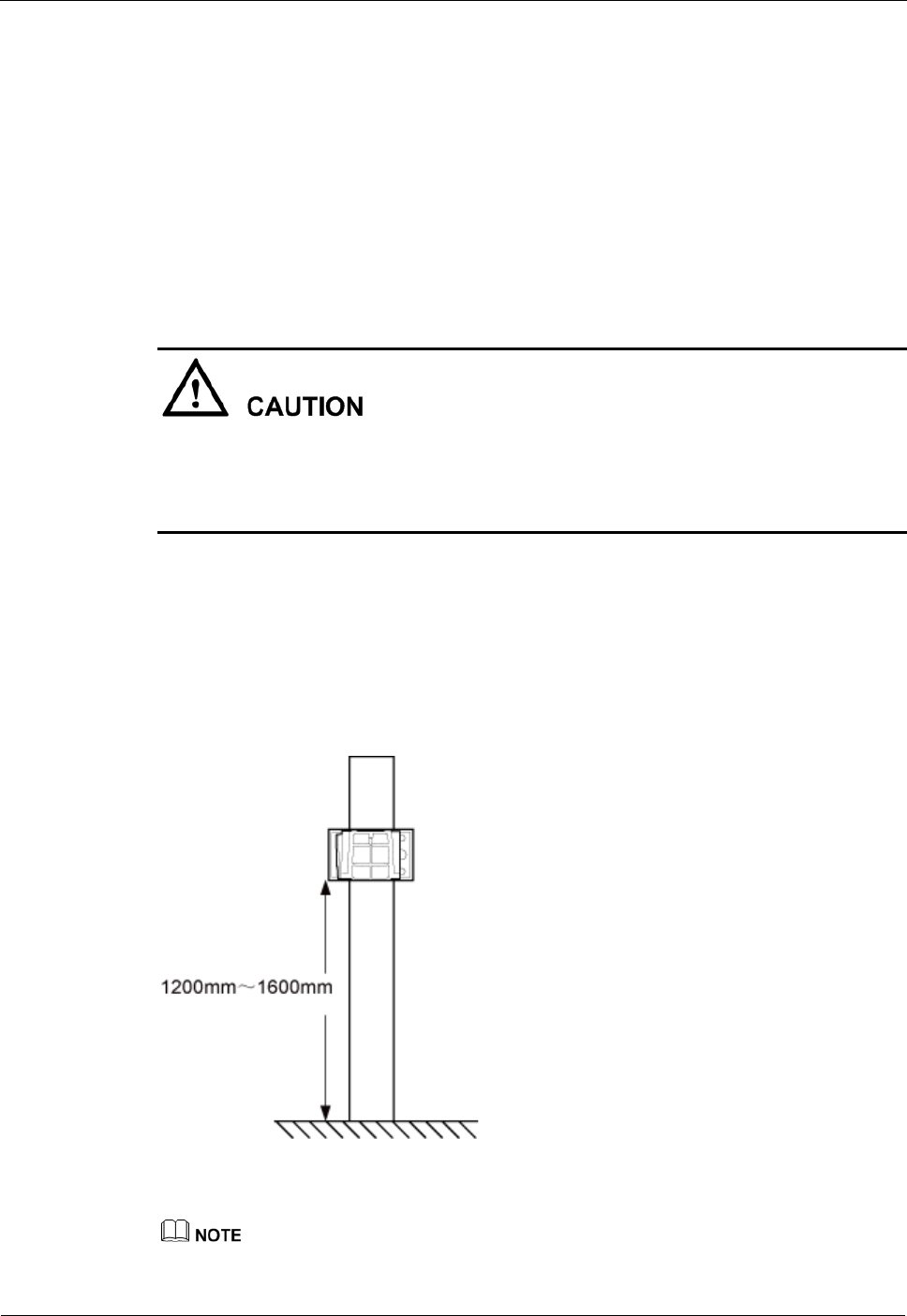
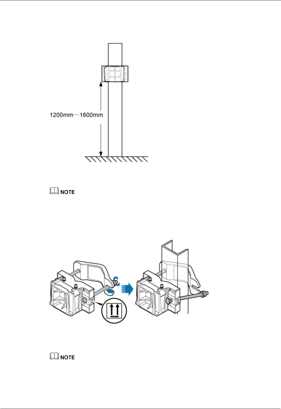
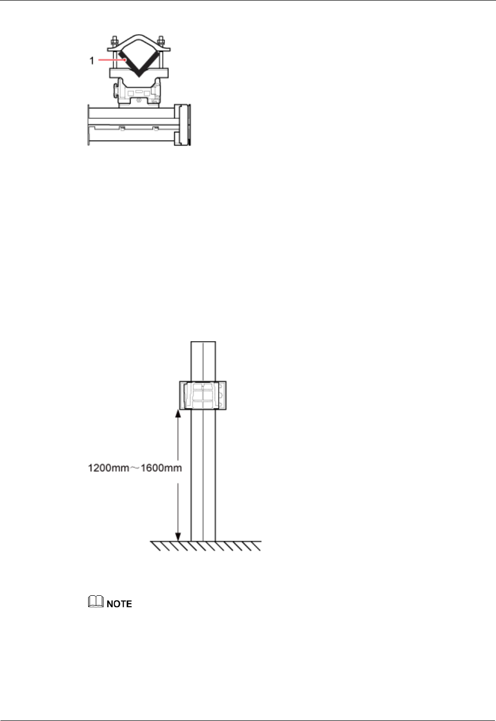
Step 1 Determine a position for installing the mounting brackets.
If the pole must be installed on the ground, determine a position for installing the
mounting brackets according to Figure 7-3.
Figure 7-3 Distance between the mounting brackets and the ground
It is recommended that the mounting brackets be installed at a height of 1200 mm (47.24 in.) to 1600
mm (62.99 in.) above the ground.
DRH
Installation Guide
7 Installing the DRH
Issue Draft A ()
Huawei Proprietary and Confidential
Copyright © Huawei Technologies Co., Ltd..
36
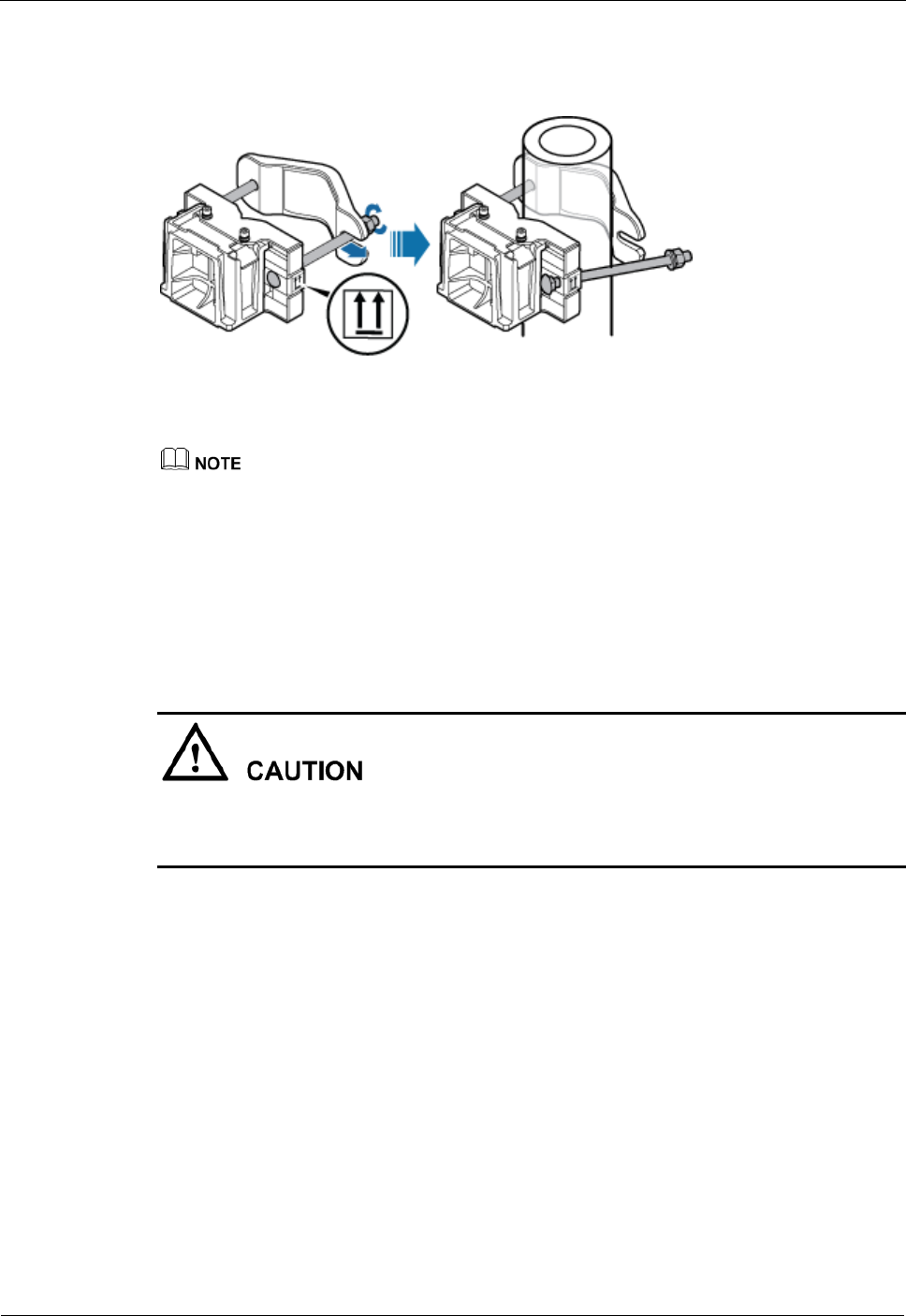
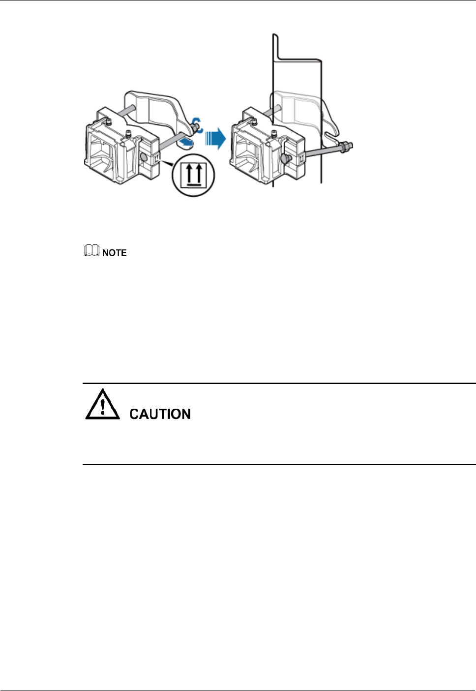
Step 2 Install the DRH mounting brackets, as shown in Figure 7-4.
Figure 7-4 Installing the DRH mounting brackets
Verify that the arrows on the mounting brackets are pointing up.
1. Adjust the position of the nut and remove one end of the square-neck bolt from the slot
on the auxiliary bracket.
2. Slide the mounting brackets onto the pole horizontally and insert the square-neck bolt
into the slot.
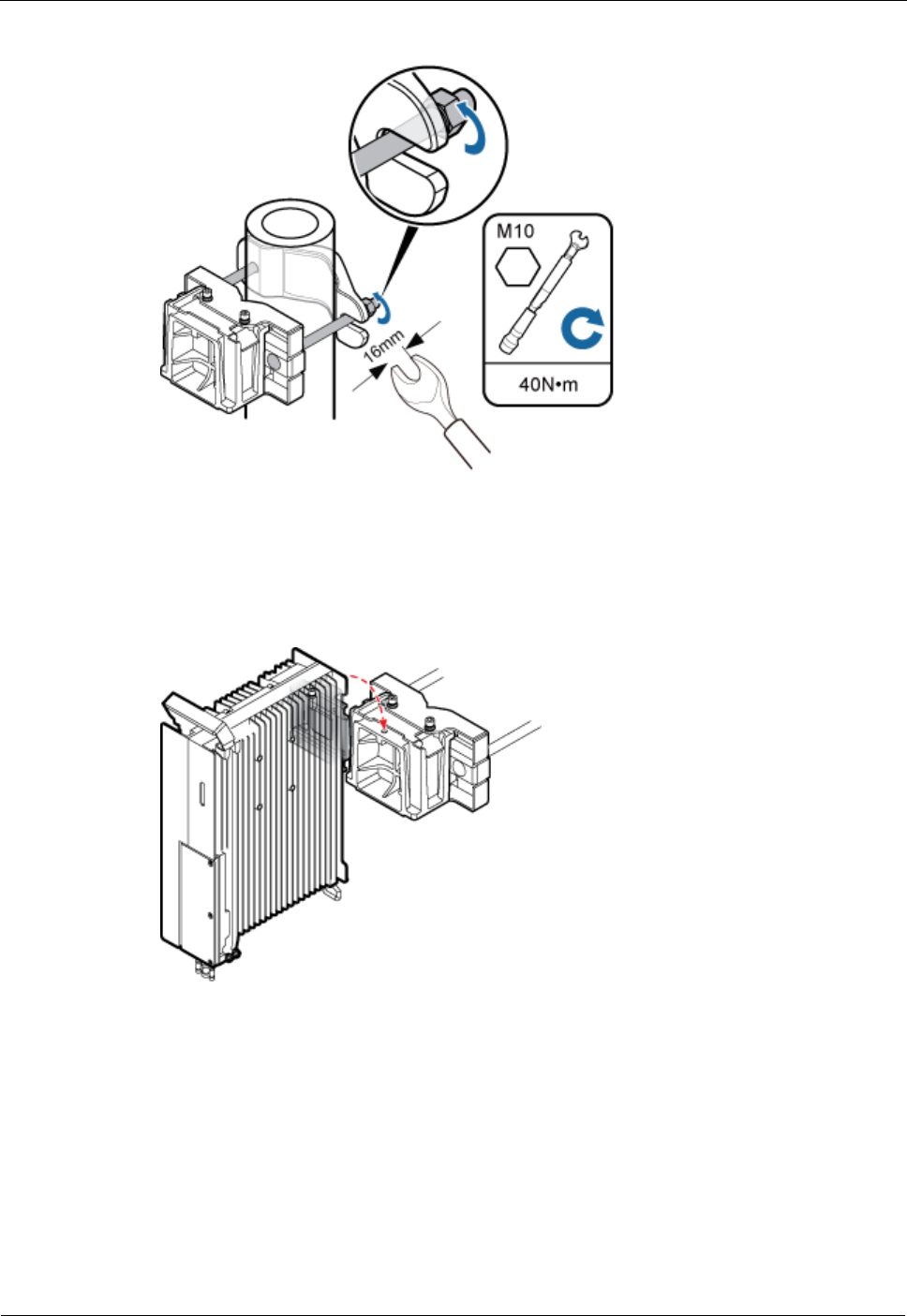
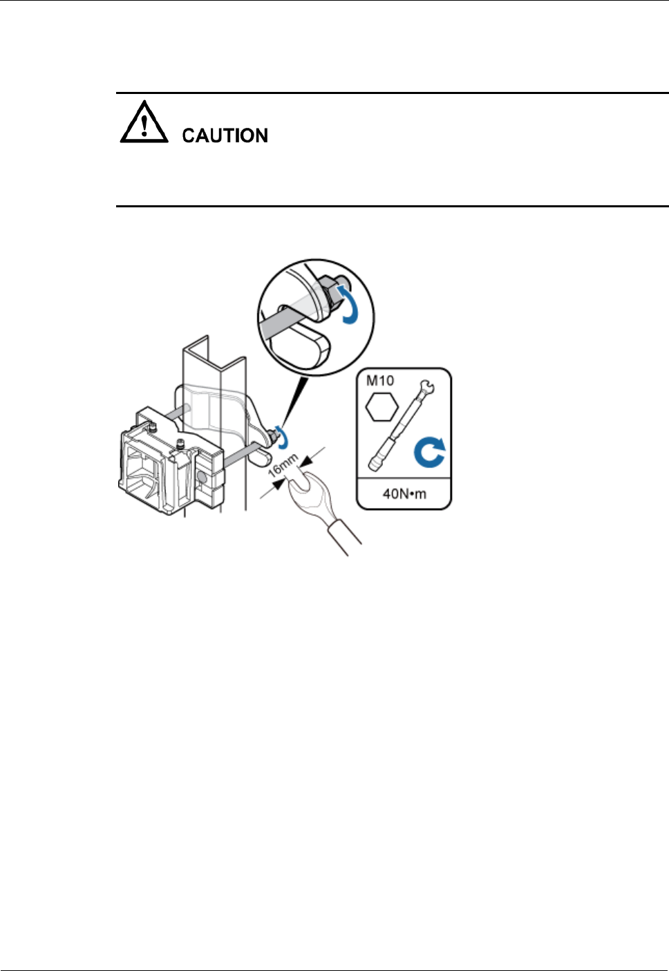
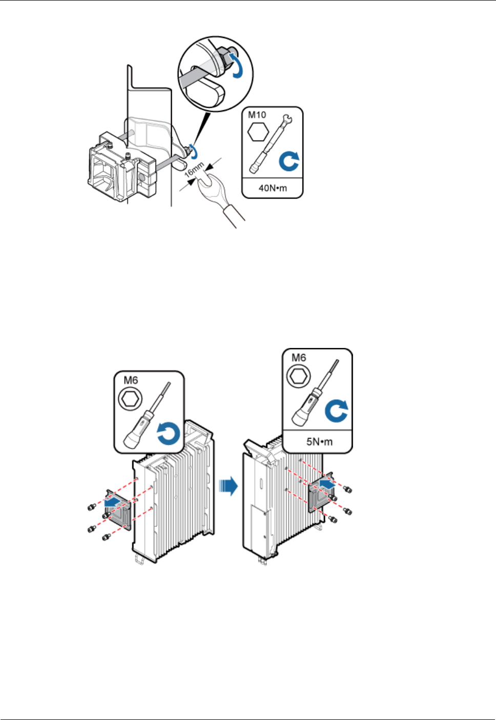
Step 3 Use a 16 mm (0.63 in.) M10 torque wrench to tighten the nuts to 40 N·m (354.03 lbf·in.) so
that the mounting brackets are secured onto the pole, as shown in Figure 7-5.
Tighten the nuts on the two square-neck bolts alternatively. After the main and auxiliary
brackets are secured properly, measure the spacing between the brackets on both sides and
ensure that the spacing is the same on the two sides.
DRH
Installation Guide
7 Installing the DRH
Issue Draft A ()
Huawei Proprietary and Confidential
Copyright © Huawei Technologies Co., Ltd..
37
Figure 7-5 Securing the DRH mounting brackets
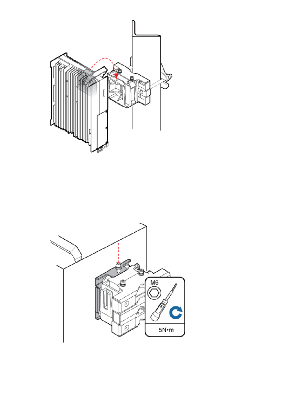
Step 4 Install the DRH onto the main bracket, as shown in Figure 7-6.
Figure 7-6 Installing the DRH onto the main bracket
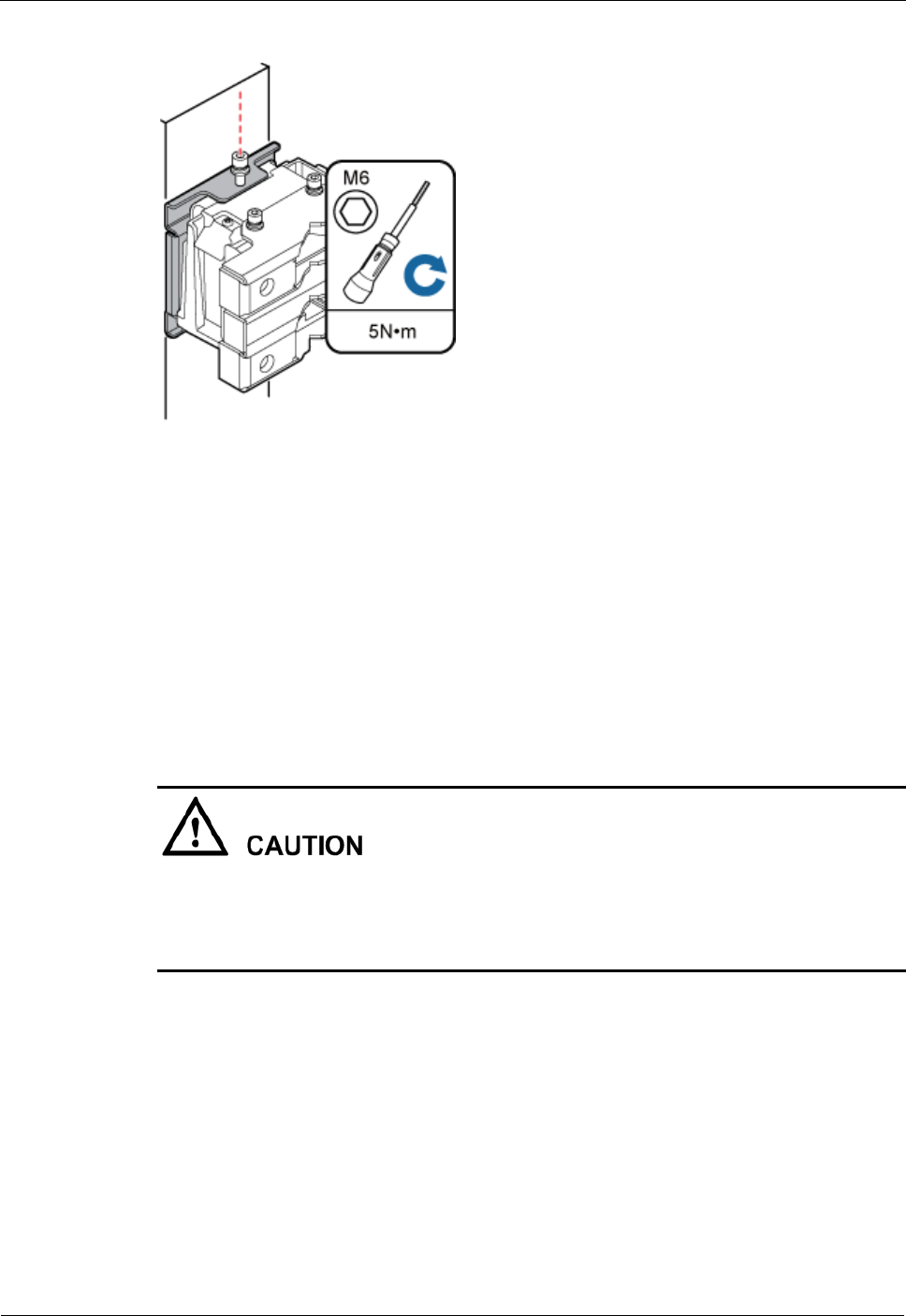
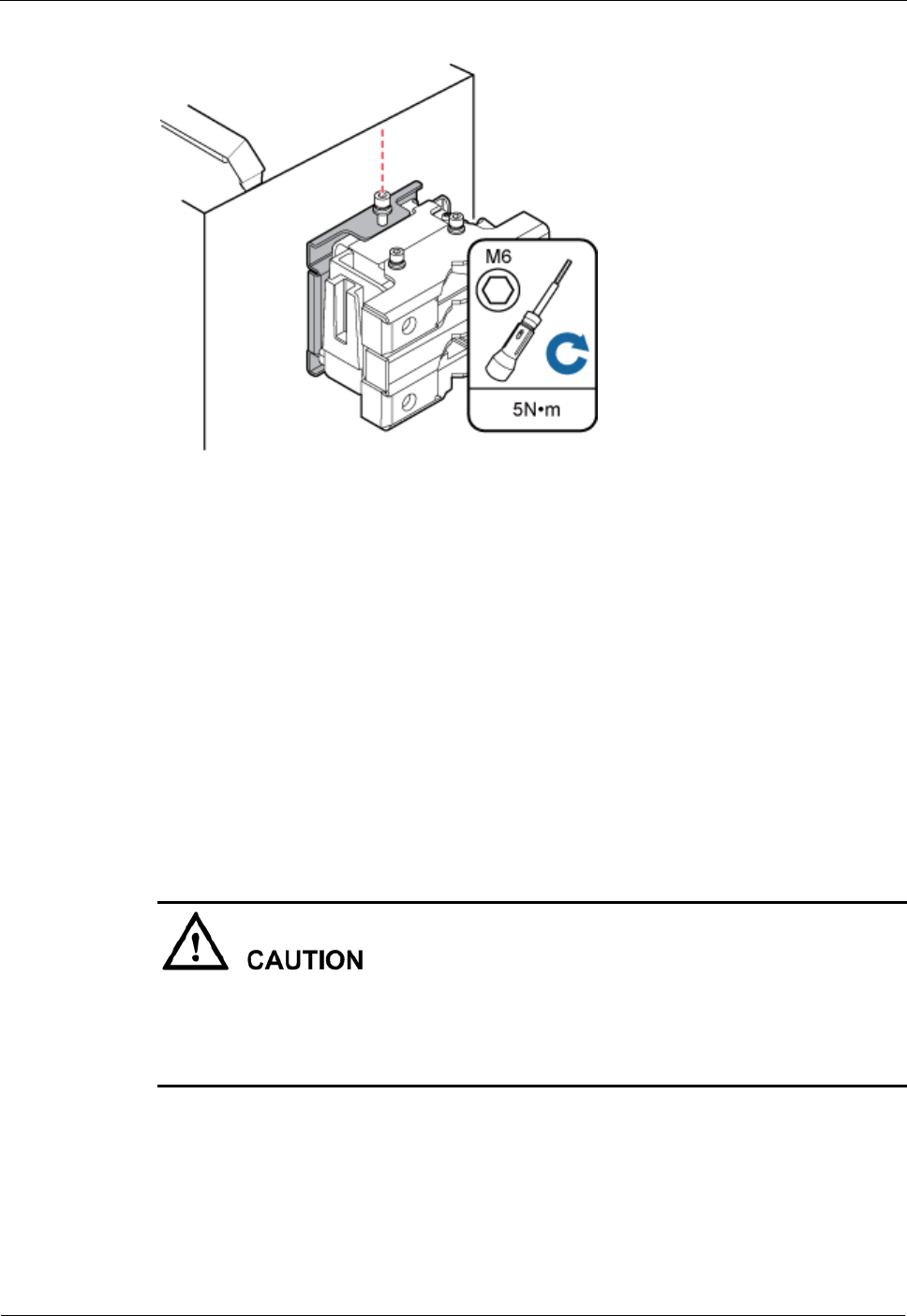
Step 5 Use an inner hexagon torque screwdriver to tighten the captive screw into the holes on the top
of the attachment plate and main bracket to 5 N·m (44.25 lbf·in.) so that the attachment plate
and main bracket are firmly secured, as shown in Figure 7-7.
DRH
Installation Guide
7 Installing the DRH
Issue Draft A ()
Huawei Proprietary and Confidential
Copyright © Huawei Technologies Co., Ltd..
38
Figure 7-7 Securing the captive screw into the connection hole
----End
Installing Two DRHs
This section describes the procedure and precautions for installing two DRHs on a pole.
Prerequisite
The hoist clamp on the main bracket is secured properly.
Do not stand the DRH upright because the RF ports cannot support the weight of the
DRH.
Place a foam pad or cardboard under the DRH to protect the DRH housing from damage
during the installation.
Procedure
Step 1 Install the first DRH onto the main bracket, as shown in Figure 7-8. For details, see Installing
a Single DRH.
DRH
Installation Guide
7 Installing the DRH
Issue Draft A ()
Huawei Proprietary and Confidential
Copyright © Huawei Technologies Co., Ltd..
39
Figure 7-8 Installing the first DRH onto the main bracket
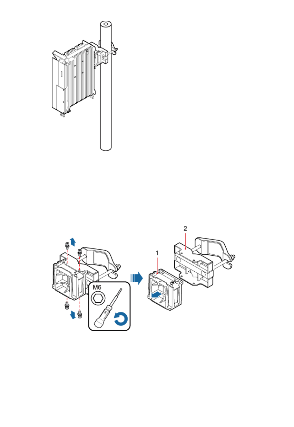
Step 2 Use an M6 inner hexagon screwdriver to remove the four inner hexagon screws from the
second set of mounting brackets, and remove the main bracket from the auxiliary bracket, as
shown in Figure 7-9.
Figure 7-9 Removing the DRH main bracket
(1) Main bracket
(2) Pole installation bracket
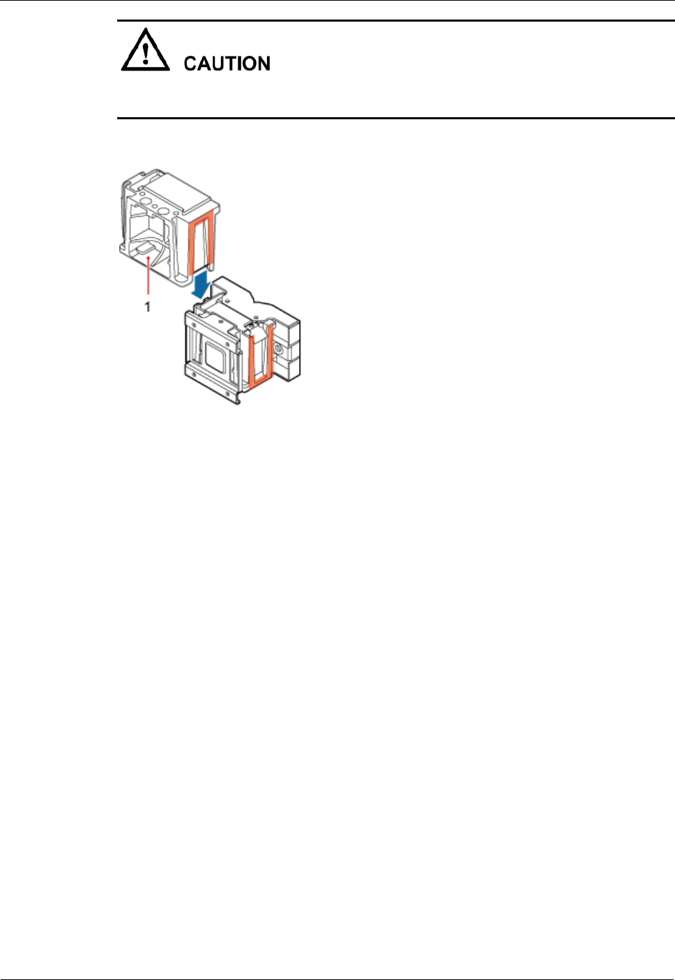
Step 3 Install the removed main bracket on one side of the first main bracket, as shown in Figure
7-10.
DRH
Installation Guide
7 Installing the DRH
Issue Draft A ()
Huawei Proprietary and Confidential
Copyright © Huawei Technologies Co., Ltd..
40
The second main bracket must be installed with the opening ends of U-shaped slots on both
sides facing downwards.
Figure 7-10 Installing the second main bracket
(1) Removed main bracket
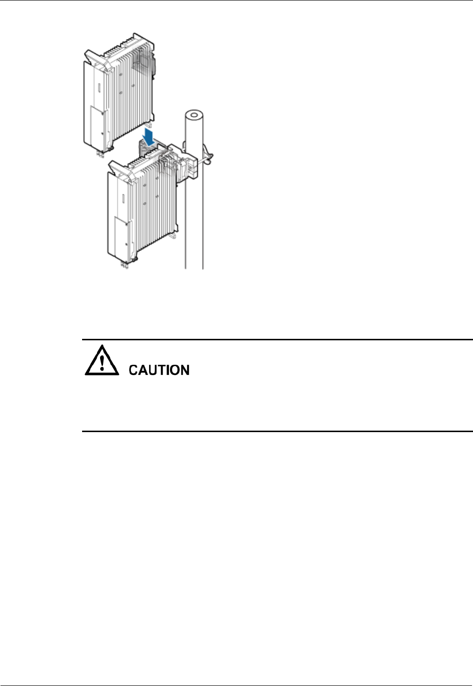
Step 4 Install the second DRH onto the main bracket, as shown in Figure 7-11.
DRH
Installation Guide
7 Installing the DRH
Issue Draft A ()
Huawei Proprietary and Confidential
Copyright © Huawei Technologies Co., Ltd..
41
Figure 7-11 Installing the second DRH onto the main bracket
After installing each DRH on its main bracket, use an inner hexagon torque screwdriver to
tighten the captive screw into the holes of the attachment plate and main bracket to 5 N·m
(44.25 lbf·in.) so that the attachment plate and main bracket are firmly secured, as shown in
Figure 7-12.
DRH
Installation Guide
7 Installing the DRH
Issue Draft A ()
Huawei Proprietary and Confidential
Copyright © Huawei Technologies Co., Ltd..
42
Figure 7-12 Securing the captive screw into the connection hole
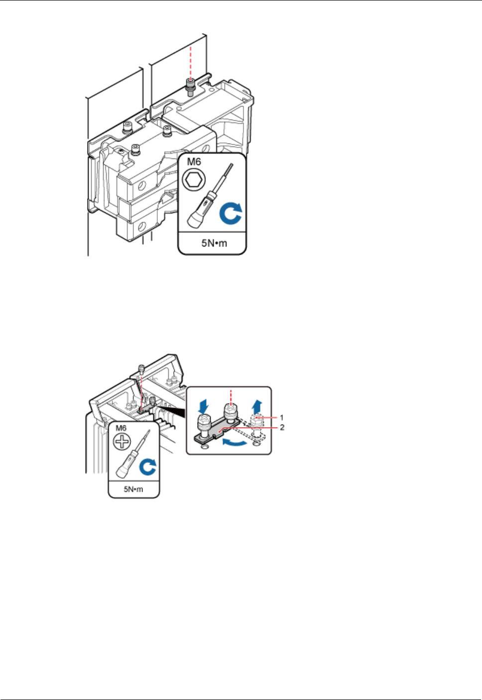
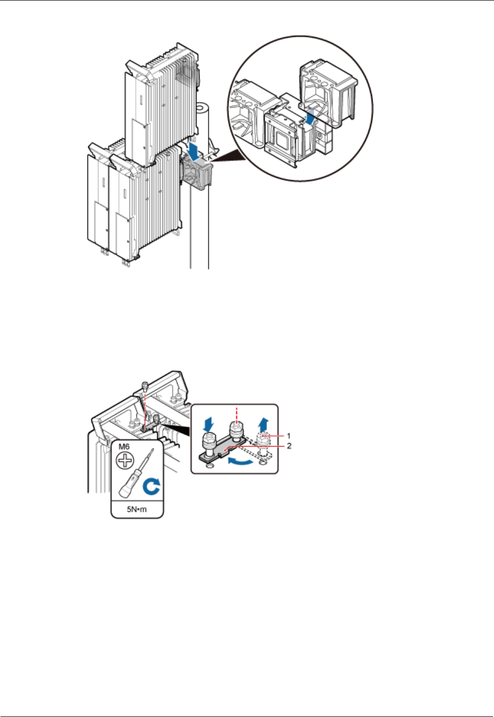
Step 5 Install the metal sheet for neighboring DRHs, as shown in Figure 7-13.
Figure 7-13 Installing the metal sheet
(1) Screw
(2) Metal sheet
1. Use an M6 Phillips screwdriver to loosen the screw on the metal sheet farther from the
handle of the first DRH and remove the screw.
2. Use an M6 Phillips screwdriver to loosen the screw on the metal sheet closer to handle of
the first DRH. Then rotate the metal sheet to align the vacant hole in the metal sheet with
a hole on the top of the second DRH.
3. Insert the removed screw into the hole on the top of the second DRH and use an M6
torque screwdriver to tighten the screw to 5 N·m (44.25 lbf·in.).
DRH
Installation Guide
7 Installing the DRH
Issue Draft A ()
Huawei Proprietary and Confidential
Copyright © Huawei Technologies Co., Ltd..
43
----End
Installing Three or More DRHs
The section describes the procedure and precautions for installing three or more DRHs on a
pole.
Prerequisite
The hoist clamp on the main bracket is secured properly.
Do not stand the DRH upright because the RF ports cannot support the weight of the
DRH.
Place a foam pad or cardboard under the DRH to protect the DRH housing from damage
during the installation.
Context
A pole supports the installation of three, four, or six DRHs. The procedures for installing them
are the same. Following is the procedure of installing four DRHs on a pole.
Procedure
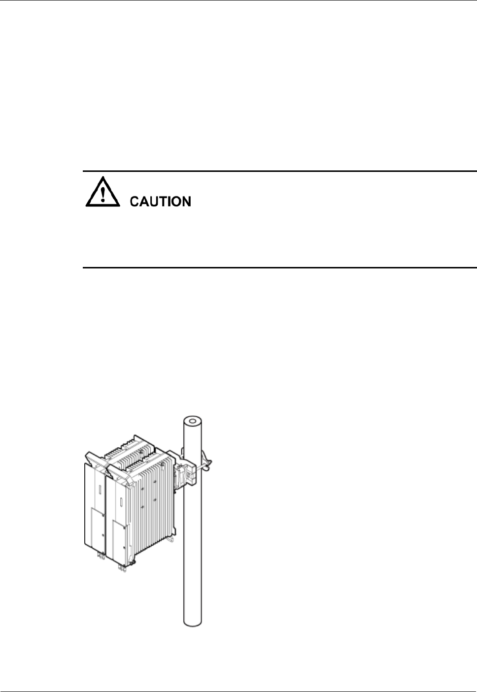
Step 1 Install the two DRHs, as shown in Figure 7-14. For details, see Installing Two DRHs.
Figure 7-14 Two DRHs installed on a pole
DRH
Installation Guide
7 Installing the DRH
Issue Draft A ()
Huawei Proprietary and Confidential
Copyright © Huawei Technologies Co., Ltd..
44
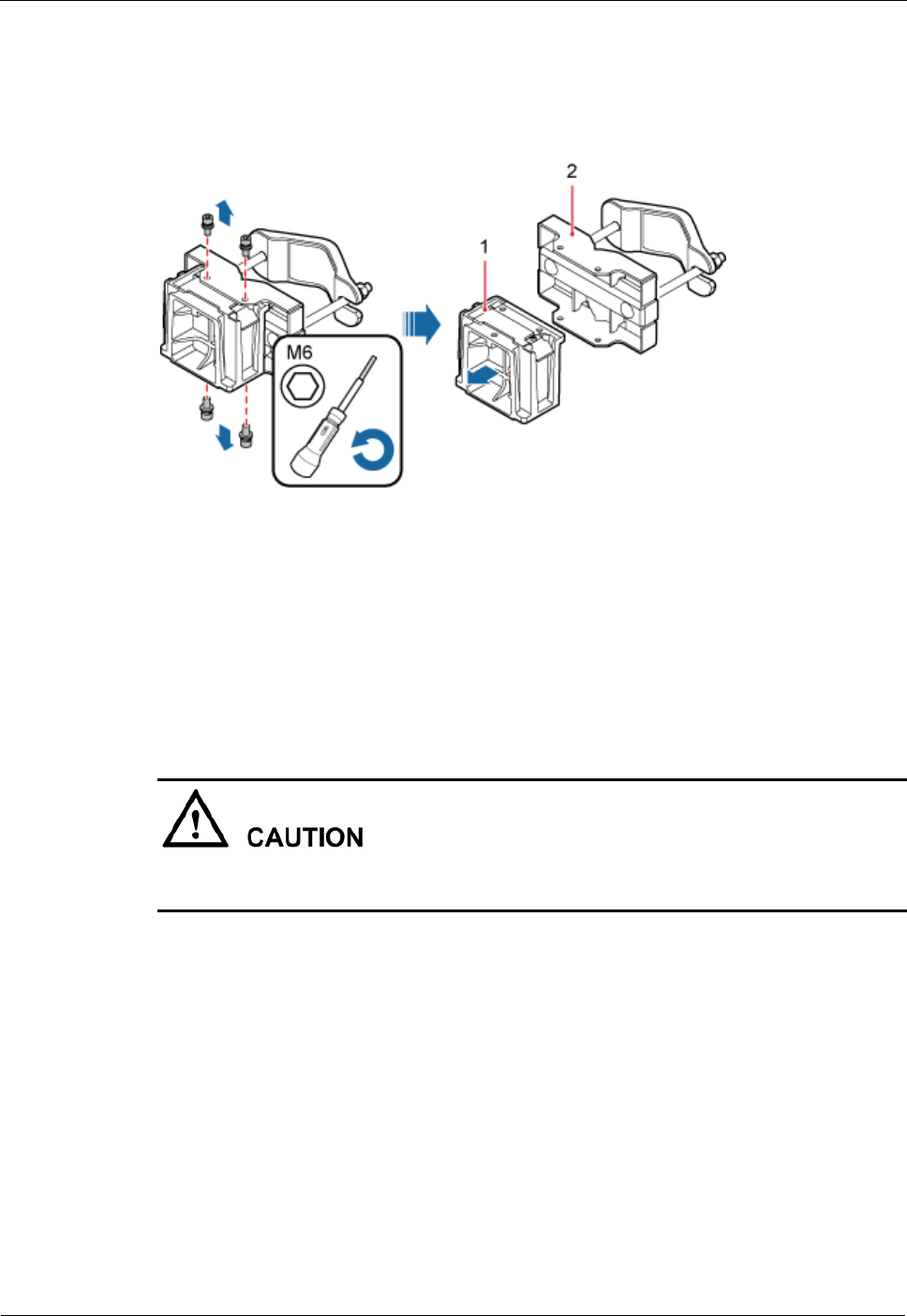
Step 2 Use an M6 inner hexagon screwdriver to remove the four inner hexagon screws from the
second set of mounting brackets, and remove the main bracket from the auxiliary bracket, as
shown in Figure 7-15.
Figure 7-15 Removing the DRH main bracket
(1) Main bracket
(2) Pole installation bracket
Step 3 Install the third main bracket and install the third DRH onto the third main bracket. Then use
an inner hexagon torque screwdriver to tighten the captive screw into the connection holes on
the top of the attachment plate and main bracket for the DRH, with a torque of 5 N·m (44.25
lbf·in.), as shown in Figure 7-16.
The third main bracket must be installed with the opening ends of U-shaped slots on both
sides facing downwards.
DRH
Installation Guide
7 Installing the DRH
Issue Draft A ()
Huawei Proprietary and Confidential
Copyright © Huawei Technologies Co., Ltd..
45
Figure 7-16 Installing the third DRH onto the third main bracket
Step 4 Install the metal sheet for neighboring DRHs, as shown in Figure 7-17.
Figure 7-17 Installing the metal sheet
(1) Screw
(2) Metal sheet
1. Use an M6 Phillips screwdriver to loosen the screw on the metal sheet farther from the
handle of the first DRH and remove the screw.
2. Use an M6 Phillips screwdriver to loosen the screw on the metal sheet closer to handle of
the first DRH. Then rotate the metal sheet to align the vacant hole in the metal sheet with
a hole on the top of the second DRH.
3. Insert the removed screw into the hole on the top of the second DRH and use an M6
torque screwdriver to tighten the screw to 5 N·m (44.25 lbf·in.).
DRH
Installation Guide
7 Installing the DRH
Issue Draft A ()
Huawei Proprietary and Confidential
Copyright © Huawei Technologies Co., Ltd..
46
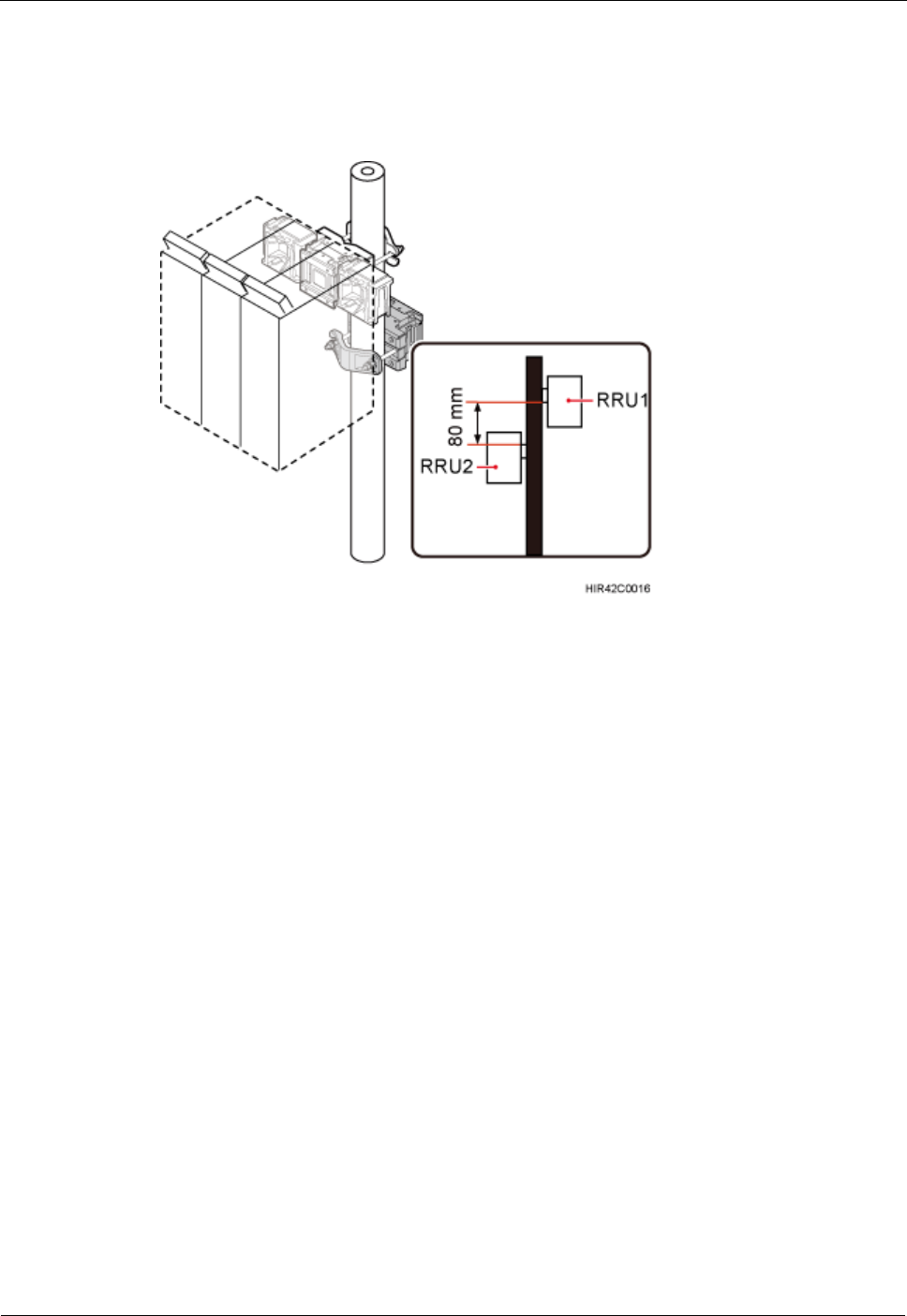
Step 5 Install the second set of DRH mounting brackets above or below the first set of DRH
mounting brackets and maintain a space equal to or greater than 80 mm (3.15 in.) between the
two sets of brackets, as shown in Figure 7-18.
Figure 7-18 Installing the second set of DRH mounting brackets
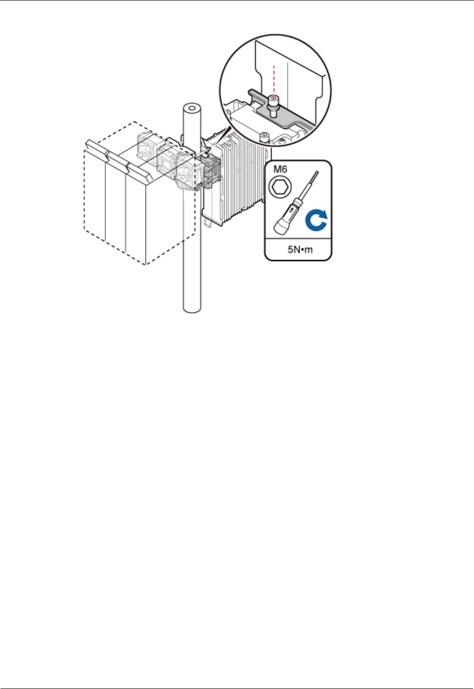
Step 6 Install the fourth DRH onto the fourth main bracket, use an inner hexagon torque screwdriver
to tighten the captive screw into the holes of the attachment plate and main bracket to 5 N·m
(44.25 lbf·in.) so that the attachment plate and main bracket are firmly secured, as shown in
Figure 7-19.
DRH
Installation Guide
7 Installing the DRH
Issue Draft A ()
Huawei Proprietary and Confidential
Copyright © Huawei Technologies Co., Ltd..
47
Figure 7-19 Installing the fourth DRH onto the fourth main bracket
----End
7.3 Installing the DRH on U-steel
This section describes the procedure and precautions for installing the DRH on U-steel. A
DRH can be installed on U-steel secured on the ground. Each piece of U-steel allows only one
DRH to be installed in standard or reverse mode.
Prerequisite
The hoist clamp on the main bracket is secured properly.
DRH
Installation Guide
7 Installing the DRH
Issue Draft A ()
Huawei Proprietary and Confidential
Copyright © Huawei Technologies Co., Ltd..
48
Do not stand the DRH upright because the RF ports cannot support the weight of the
DRH.
Place a foam pad or cardboard under the DRH to protect the DRH housing from damage
during the installation.
Context
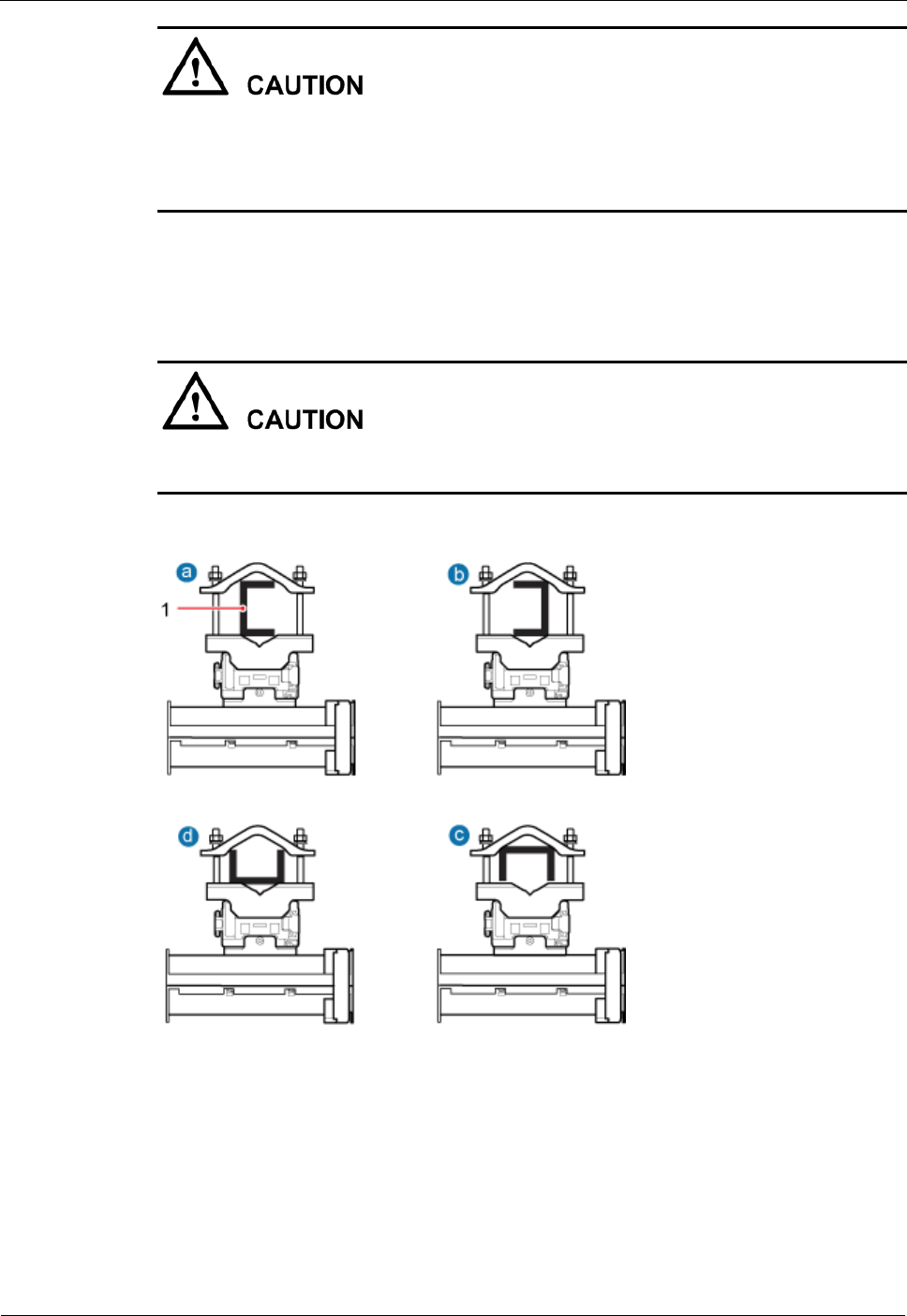
Figure 7-20 shows the top view of the DRH installed on U-steel.
When the width of the narrower edges of the U-steel is less than 40 mm (1.57 in.), only the a
and b modes are supported.
Figure 7-20 Top view of the DRH
(1) U-steel
Procedure
Step 1 Determine a position for installing the mounting brackets.
DRH
Installation Guide
7 Installing the DRH
Issue Draft A ()
Huawei Proprietary and Confidential
Copyright © Huawei Technologies Co., Ltd..
49
If the DRH must be installed on U-steel secured on the ground, see Figure 7-21 to
determine a position.
Figure 7-21 Distance between the mounting brackets and the ground
It is recommended that the mounting brackets be installed at a height of 1200 mm (47.24 in.) to 1600
mm (62.99 in.) above the ground.
Step 2 Install the DRH mounting brackets, as shown in Figure 7-22.
Figure 7-22 Installing the DRH mounting brackets
Verify that the arrows on the mounting brackets are pointing up.
1. Adjust the position of the nut and remove one end of the square-neck bolt from the slot
on the auxiliary bracket.
2. Slide the mounting brackets onto the U-steel horizontally and insert the square-neck bolt
into the slot.
DRH
Installation Guide
7 Installing the DRH
Issue Draft A ()
Huawei Proprietary and Confidential
Copyright © Huawei Technologies Co., Ltd..
50
Step 3 Use a 16 mm (0.67 in.) M10 torque wrench to tighten the nuts to 40 N·m (354.03 lbf·in.) so
that the mounting brackets are secured onto the U-steel, as shown in Figure 7-23.
Tighten the nuts on the two square-neck bolts alternatively. After the main and auxiliary
brackets are secured properly, measure the spacing between the brackets on both sides and
ensure that the spacing is the same on the two sides.
Figure 7-23 Securing the DRH mounting brackets
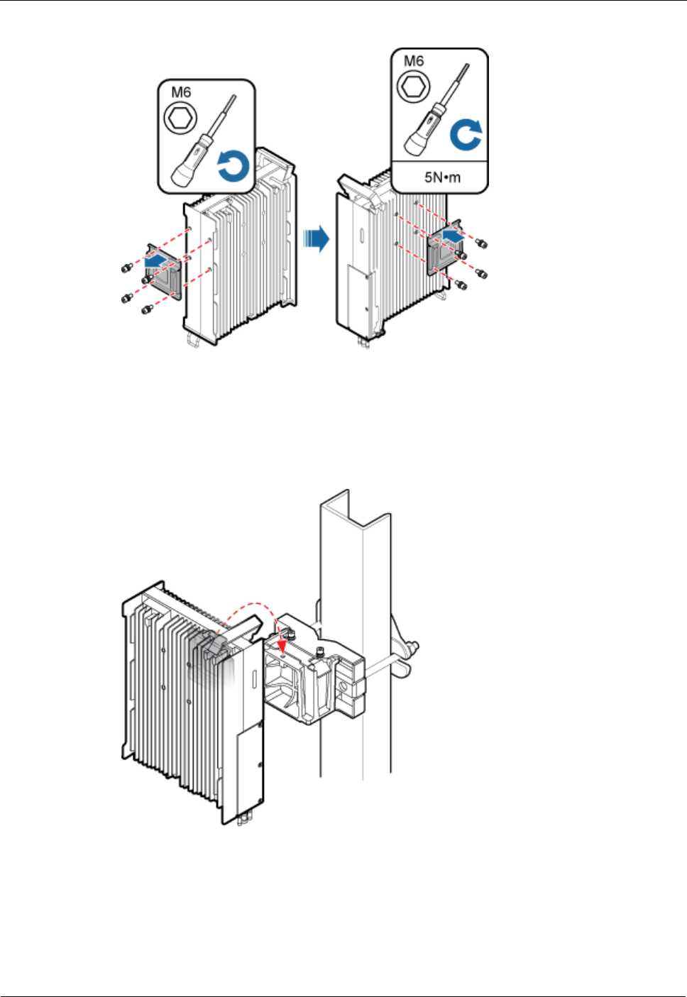
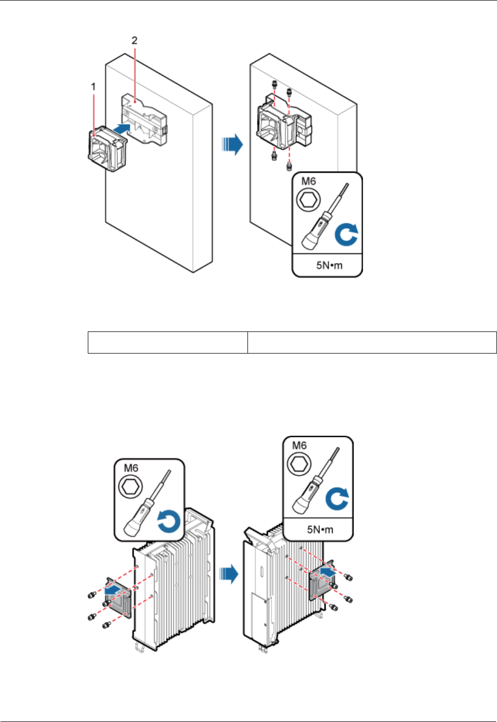
Step 4 Use an inner hexagon screwdriver to remove the attachment plate from one side of the DRH,
reinstall the attachment plate onto the rear of the DRH, and tighten the four stainless screws to
5 N·m (44.25 lbf·in.), as shown in Figure 7-24.
DRH
Installation Guide
7 Installing the DRH
Issue Draft A ()
Huawei Proprietary and Confidential
Copyright © Huawei Technologies Co., Ltd..
51
Figure 7-24 Installing the attachment plate onto the rear of the DRH
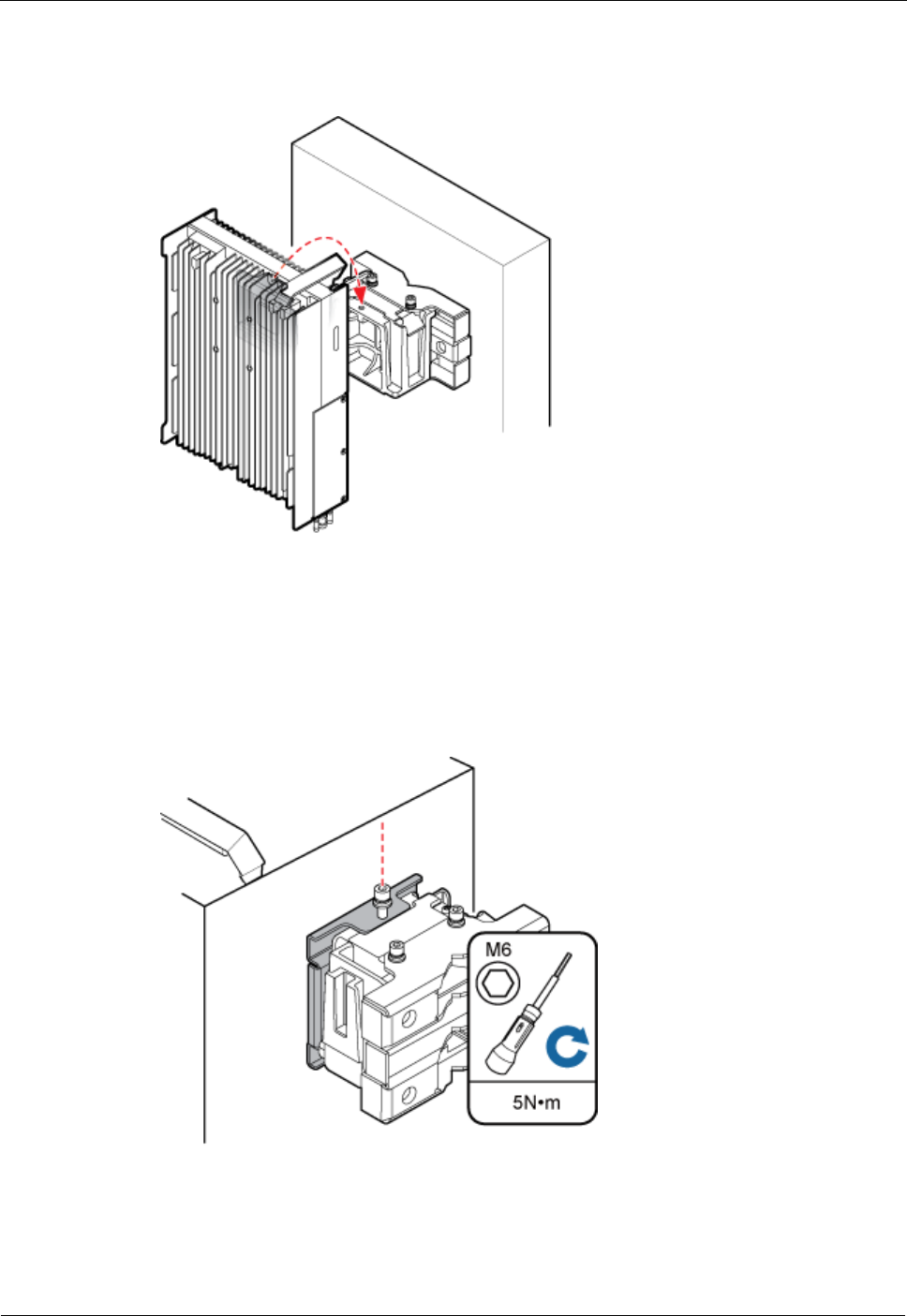
Step 5 Install the DRH onto the main bracket, as shown in Figure 7-25.
Figure 7-25 Installing the DRH onto the main bracket
Step 6 Use an inner hexagon screwdriver to tighten the captive screw into the holes on the top of the
attachment plate and main bracket to 5 N·m (44.25 lbf·in.) so that the attachment plate and
main bracket are firmly secured, as shown in Figure7-26.
DRH
Installation Guide
7 Installing the DRH
Issue Draft A ()
Huawei Proprietary and Confidential
Copyright © Huawei Technologies Co., Ltd..
52
Figure 7-26 Securing the captive screw into the connection hole
----End
7.4 Installing the DRH on Angle Steel
This section describes the procedure and precautions for installing the DRH on angle steel. A
DRH can be installed on angle steel secured on the ground. Each piece of angle steel allows
only one DRH to be installed in standard or reverse mode.
Prerequisite
The hoist clamp on the main bracket is secured properly.
Do not stand the DRH upright because the RF ports cannot support the weight of the
DRH.
Place a foam pad or cardboard under the DRH to protect the DRH housing from damage
during the installation.
Context
Figure 7-27 shows the top view of the DRH installed on angle steel.
DRH
Installation Guide
7 Installing the DRH
Issue Draft A ()
Huawei Proprietary and Confidential
Copyright © Huawei Technologies Co., Ltd..
53
Figure 7-27 Top view of the DRH
(1) Angle steel
Procedure
Step 1 Determine a position for installing the mounting brackets.
If the DRH must be installed on angle steel secured on the ground, see Figure 7-28 to
determine a position.
Figure 7-28 Distance between the mounting brackets and the ground
It is recommended that the mounting brackets be installed at a height of 1200 mm (47.24 in.) to 1600
mm (62.99 in.) above the ground.
Step 2 Install the DRH mounting brackets, as shown in Figure 7-29.
DRH
Installation Guide
7 Installing the DRH
Issue Draft A ()
Huawei Proprietary and Confidential
Copyright © Huawei Technologies Co., Ltd..
54
Figure 7-29 Installing the DRH mounting brackets
Verify that the arrows on the mounting brackets are pointing up.
1. Adjust the position of the nut and remove one end of the square-neck bolt from the slot
on the auxiliary bracket.
2. Slide the mounting brackets onto the angle steel horizontally and insert the square-neck
bolt into the slot.
Step 3 Use a 16 mm (0.67 in.) M10 torque wrench to tighten the nuts to 40 N·m (354.03 lbf·in.) so
that the mounting brackets are secured onto the angle steel, as shown in Figure 7-30.
Tighten the nuts on the two square-neck bolts alternatively. After the main and auxiliary
brackets are secured properly, measure the spacing between the brackets on both sides and
ensure that the spacing is the same on the two sides.
DRH
Installation Guide
7 Installing the DRH
Issue Draft A ()
Huawei Proprietary and Confidential
Copyright © Huawei Technologies Co., Ltd..
55
Figure 7-30 Securing the DRH mounting brackets
Step 4 Use an inner hexagon screwdriver to remove the attachment plate from one side of the DRH,
reinstall the attachment plate onto the rear of the DRH, and tighten the four stainless screws to
5 N·m (44.25 lbf·in.), as shown in Figure 7-31.
Figure 7-31 Installing the attachment plate onto the rear of the DRH
Step 5 Install the DRH onto the main bracket, as shown in Figure 7-32.
DRH
Installation Guide
7 Installing the DRH
Issue Draft A ()
Huawei Proprietary and Confidential
Copyright © Huawei Technologies Co., Ltd..
56
Figure 7-32 Installing the DRH onto the main bracket
Step 6 Use an inner hexagon screwdriver to tighten the captive screw into the holes on the top of the
attachment plate and main bracket to 5 N·m (44.25 lbf·in.) so that the attachment plate and
main bracket are firmly secured, as shown in Figure 7-33.
Figure 7-33 Securing the captive screw into the connection hole
----End

DRH
Installation Guide
7 Installing the DRH
Issue Draft A ()
Huawei Proprietary and Confidential
Copyright © Huawei Technologies Co., Ltd..
57
7.5 Installing the DRH on a Wall
This section describes the procedure and precautions for installing the DRH on a wall.
Prerequisite
The hoist clamp on the main bracket is secured properly.
Do not stand the DRH upright because the RF ports cannot support the weight of the
DRH.
Place a foam pad or cardboard under the DRH to protect the DRH housing from damage
during the installation.
Context
The wall on which DRHs are installed must meet the following requirements:
When a single DRH is installed, the wall must be capable of bearing at least four times
the weight of the DRH.
Expansion anchor bolts must be tightened to 30 N·m (265.52 lbf·in.) so that the bolts
stay secured without damaging the wall.
Procedure
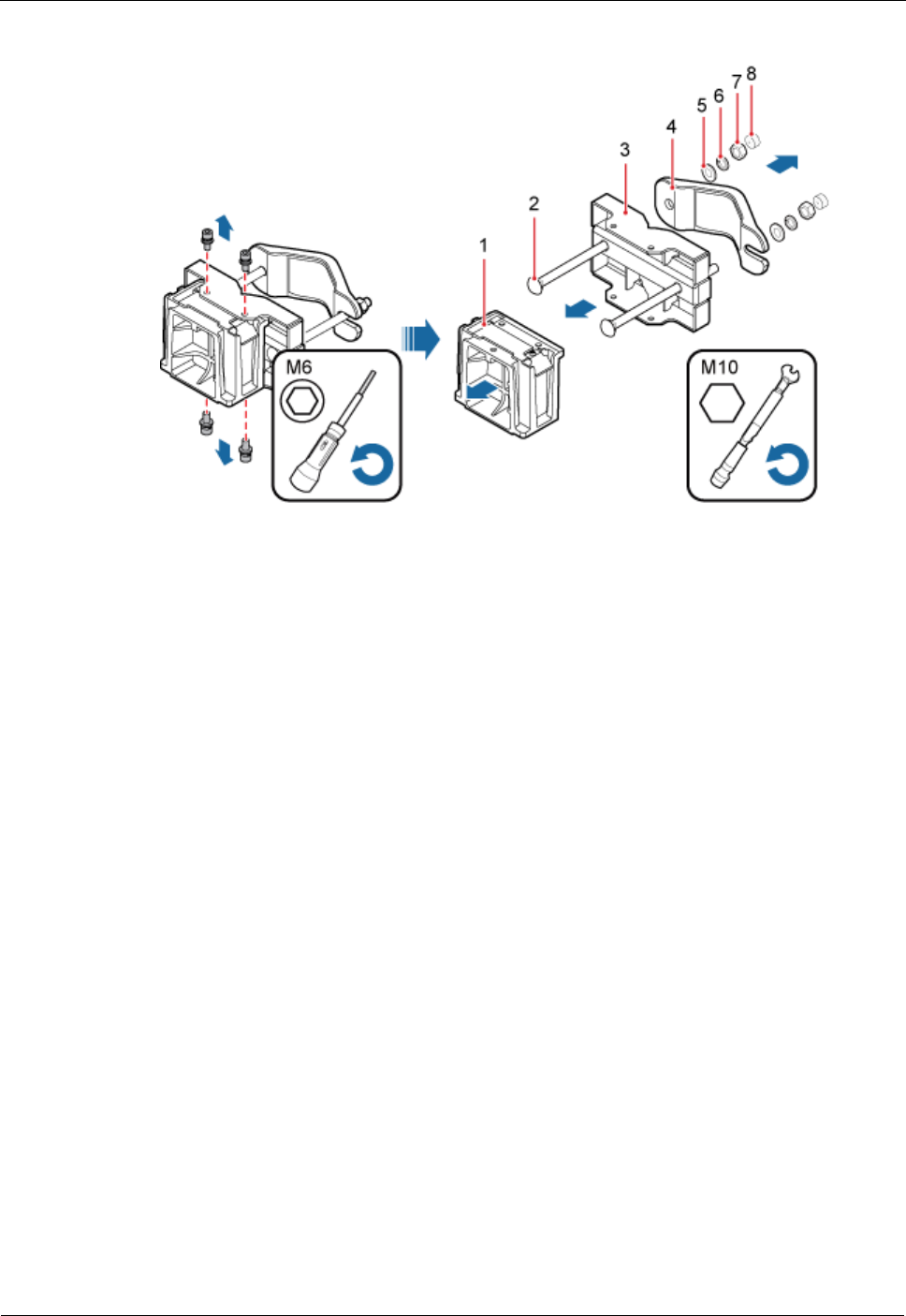
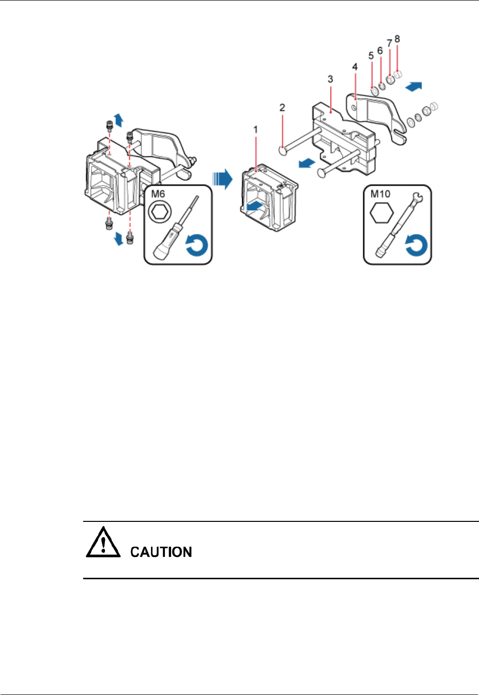
Step 1 Disassemble the DRH mounting brackets, as shown in Figure 7-34.
DRH
Installation Guide
7 Installing the DRH
Issue Draft A ()
Huawei Proprietary and Confidential
Copyright © Huawei Technologies Co., Ltd..
58
Figure 7-34 Disassembling the mounting brackets
(1) Main
bracket
(2) Square-neck
bolt
(3) Pole installation
bracket
(4) Auxiliary
bracket
(5) Flat washer
(6) Spring washer
(7) Nut
(8) Plastic cap
1. Use an M6 inner hexagon torque screwdriver to remove the four inner hexagon screws
on the pole installation bracket, and remove the main bracket from the pole installation
bracket.
2. Use an M10 torque wrench to loosen the nuts on the two square-neck bolts, and remove
the plastic cap, nuts, spring washers, flat washers, square-neck bolts, and pole
installation bracket from the auxiliary bracket.
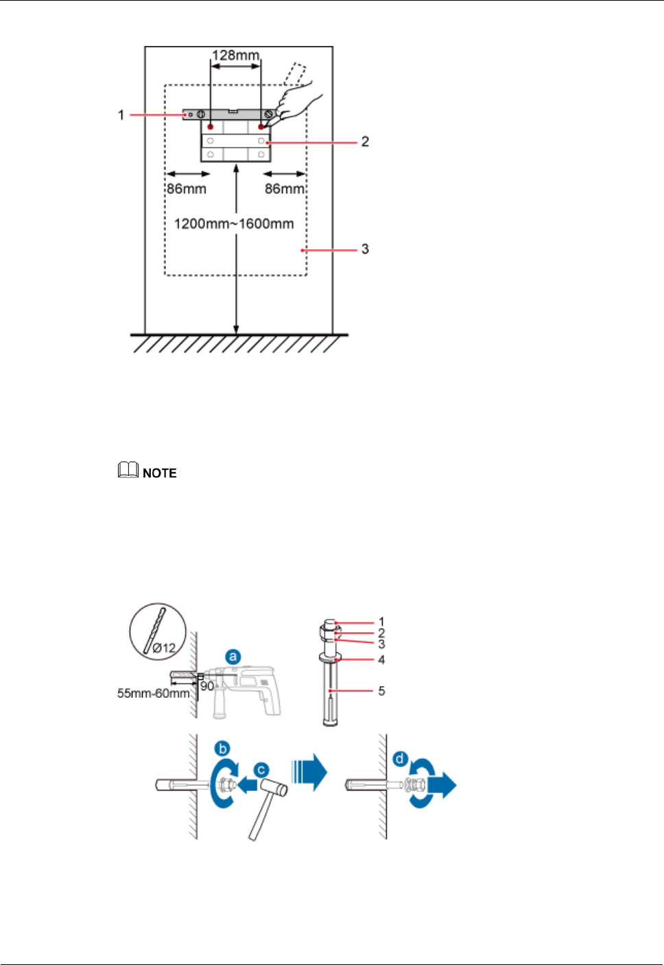
Step 2 Place the pole installation bracket against the installation position, use a level to verify that
the pole installation bracket is placed horizontally, and then mark anchor points with a marker,
as shown in Figure 7-35.
DRH
Installation Guide
7 Installing the DRH
Issue Draft A ()
Huawei Proprietary and Confidential
Copyright © Huawei Technologies Co., Ltd..
59
Figure 7-35 Marking anchor points
(1) Level
(2) Pole installation bracket
(3) DRH
It is recommended that the pole installation bracket be installed at a height of 1200 mm (47.24 in.) to
1600 mm (62.99 in.) above the ground.
Step 3 Drill holes at the anchor points, and then insert expansion anchor bolt assemblies, as shown in
Figure 7-36.
Figure 7-36 Drilling a hole and inserting expansion anchor bolt assemblies
(1) M10x80 bolt
(2) Nut
(3) Spring
washer
(4) Flat washer
(5) Expansion
tube
DRH
Installation Guide
7 Installing the DRH
Issue Draft A ()
Huawei Proprietary and Confidential
Copyright © Huawei Technologies Co., Ltd..
60
1. Use a hammer drill with a Ф12 bit to drill holes vertically at the marked anchor points.
Ensure that the depth of each hole ranges from 55 mm (2.17 in.) to 60 mm (2.36 in.).
Take proper safety measures to protect your eyes and respiratory tract against the dust before
drilling holes.
2. Tighten the expansion anchor bolts slightly and place one vertically into each hole.
3. Use a rubber mallet to pound the expansion anchor bolt until it goes all the way into the
hole.
4. Tighten and then loosen the expansion bolt, and remove the M10 bolt, spring washer,
and flat washer in sequence.
After dismantling an expansion anchor bolt, ensure that the top of the expansion tube is on the
same level as the wall. Otherwise, the device cannot be installed on the wall evenly and
securely.
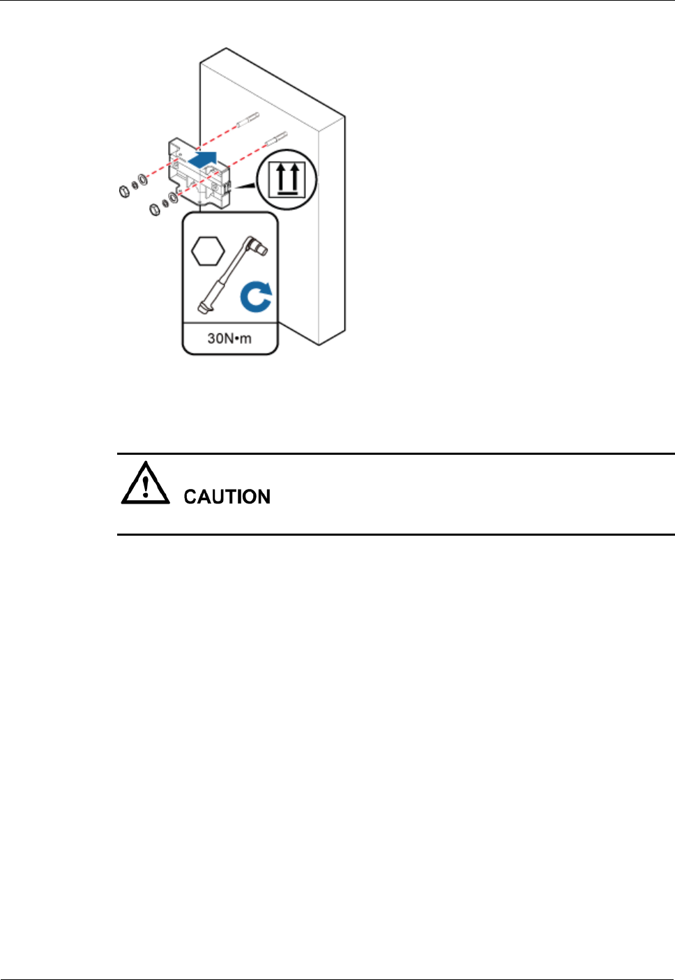
Step 4 Install the pole installation bracket on the expansion anchor bolts, place the flat washers,
spring washers, and nuts through the expansion anchor bolts in sequence, and then use a 16
mm (0.63 in.) torque socket to tighten the nuts to 30 N·m (265.52 lbf·in.), as shown in Figure
7-37.
DRH
Installation Guide
7 Installing the DRH
Issue Draft A ()
Huawei Proprietary and Confidential
Copyright © Huawei Technologies Co., Ltd..
61
Figure 7-37 Installing the pole installation bracket on the expansion anchor bolts
Verify that the arrows on the pole installation bracket are pointing up.
Step 5 Install the main bracket onto the pole installation bracket, and use an inner hexagon
screwdriver to tighten four M6x16 inner hexagon screws to 5 N·m (44.25 lbf·in.) so that the
main bracket and pole installation bracket are firmly secured, as shown in Figure 7-38.
DRH
Installation Guide
7 Installing the DRH
Issue Draft A ()
Huawei Proprietary and Confidential
Copyright © Huawei Technologies Co., Ltd..
62
Figure 7-38 Installing the main bracket
(1) Main bracket
(2) Pole installation bracket
Step 6 Use an inner hexagon screwdriver to remove the attachment plate from one side of the DRH,
reinstall the attachment plate onto the rear of the DRH, and tighten the four stainless screws to
5 N·m (44.25 lbf·in.), as shown in Figure 7-39.
Figure 7-39 Installing the attachment plate onto the rear of the DRH
DRH
Installation Guide
7 Installing the DRH
Issue Draft A ()
Huawei Proprietary and Confidential
Copyright © Huawei Technologies Co., Ltd..
63
Step 7 Install the DRH onto the main bracket, as shown in Figure 7-40.
Figure 7-40 Installing the DRH onto the main bracket
Step 8 Use an inner hexagon screwdriver to tighten the captive screw into the holes on the top of the
attachment plate and main bracket to 5 N·m (44.25 lbf·in.) so that the attachment plate and
main bracket are firmly secured, as shown in Figure 7-41.
Figure 7-41 Securing the captive screw into the connection hole
----End

DRH
Installation Guide
7 Installing the DRH
Issue Draft A ()
Huawei Proprietary and Confidential
Copyright © Huawei Technologies Co., Ltd..
64
7.6 Installing a DRH on an IFS06
This section describes the procedure and precautions for installing a DRH on an IFS06.
Prerequisite
The hoist clamp on the main bracket is secured properly.
Do not stand the DRH upright because the RF ports cannot support the weight of the
DRH.
Place a foam pad or cardboard under the DRH to protect the DRH housing from damage
during the installation.
Context
The upper and lower adjustable beams on an IFS06 can be moved up and down to fit for
heights of DRHs.
DRHs can be installed on an IFS06 only when the ambient temperature is higher than or
equal to the lowest working temperature of the DRH and at least 5°C (41°F) lower than
the highest working temperature of the DRH. In this scenario, the IFS06 supports at least
three DRHs. When the ambient temperature is higher than or equal to the lowest working
temperature of the DRH and at least 10°C (50°F) lower than the highest working
temperature of the DRH, the IFS06 supports a maximum of six DRHs.
Install DRHs in the sequence from bottom to top and from left to right.
This section describes how to install a DRH in height-unrestricted scenarios. The
procedure for installing a DRH in height-restricted scenarios is the same as that in
height-unrestricted scenarios.
When installing the pole installation bracket, you need to use the M10x50 bolts delivered
with the IFS06.
Rubber washers are easily compressed or broken, whereas do not need to be replaced.
Procedure
Step 1 Disassemble the DRH mounting brackets, as shown in Figure 7-42.
DRH
Installation Guide
7 Installing the DRH
Issue Draft A ()
Huawei Proprietary and Confidential
Copyright © Huawei Technologies Co., Ltd..
65
Figure 7-42 Disassembling the mounting brackets
(1) Main
bracket
(2) Square-neck
bolt
(3) Pole installation
bracket
(4) Auxiliary
bracket
(5) Flat washer
(6) Spring washer
(7) Nut
(8) Plastic cap
1. Use an M6 inner hexagon torque screwdriver to remove the four inner hexagon screws
on the pole installation bracket, and remove the main bracket from the pole installation
bracket.
2. Use an M10 torque wrench to loosen the nuts on the two square-neck bolts, and remove
the plastic cap, nuts, spring washers, flat washers, square-neck bolts, and pole
installation bracket from the auxiliary bracket.
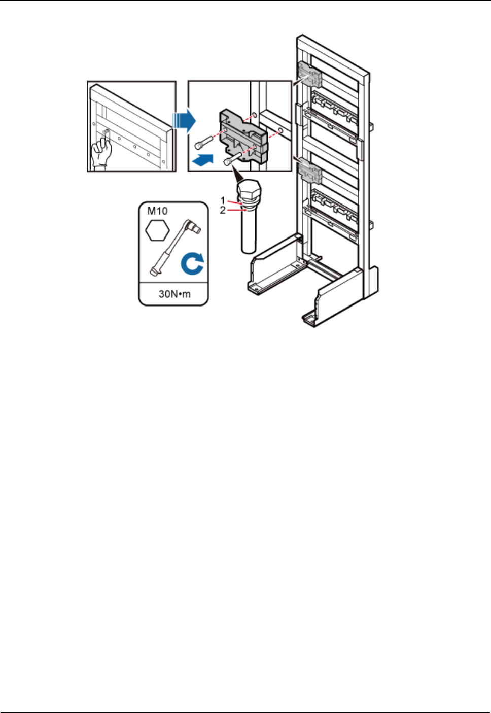
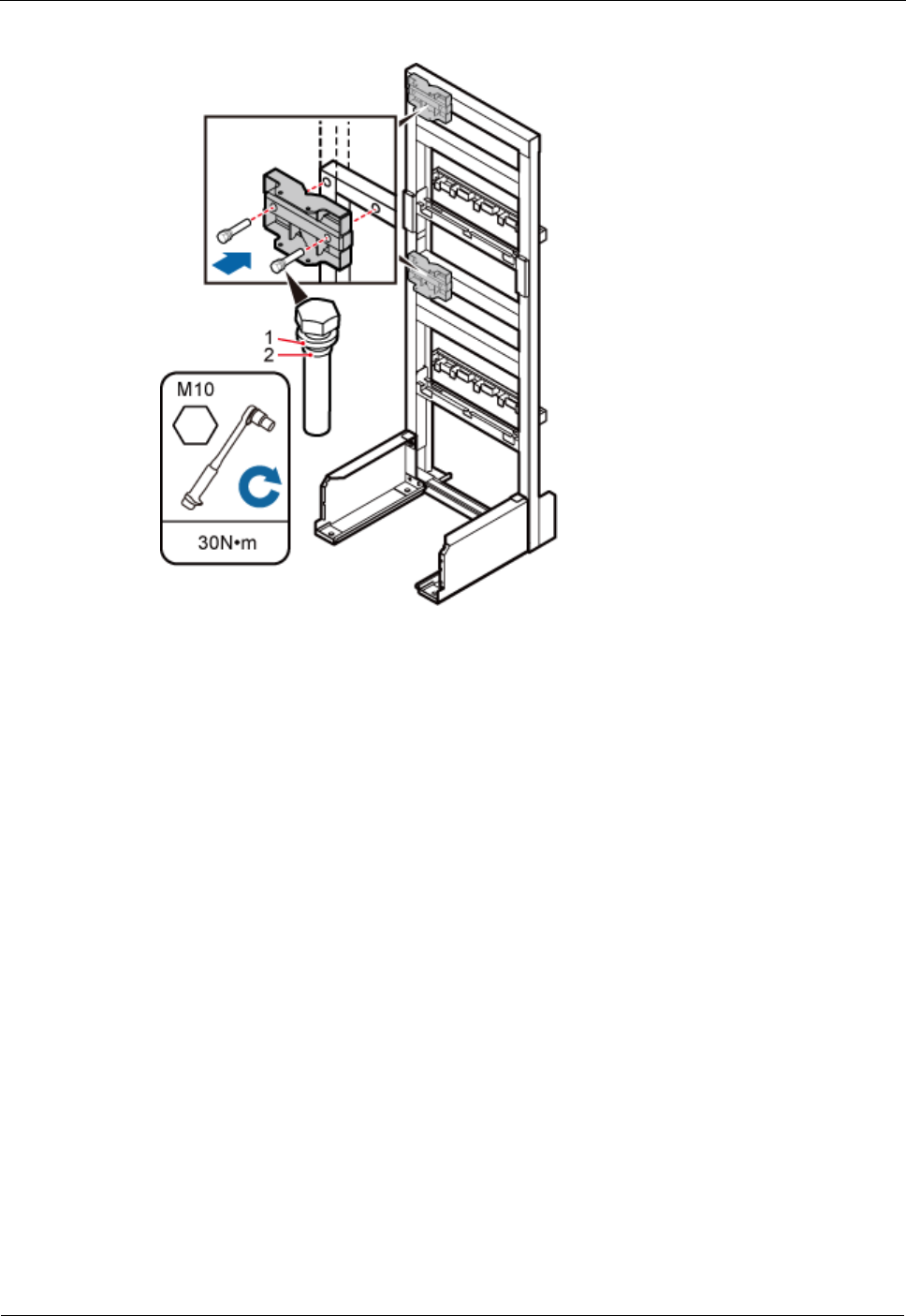
Step 2 Use the M10x50 bolts delivered with the IFS06 to secure the pole installation bracket to the
IFS06, and then use an M10 torque socket wrench to secure the bolts to 30 N·m (265.52
lbf·in.).
Ensure that the arrows on the pole installation bracket are pointing up.
Height-restricted scenarios
Use one finger to push and remove the rubber plugs on the beam and then install the pole
installation bracket, as shown in Figure 7-43.
DRH
Installation Guide
7 Installing the DRH
Issue Draft A ()
Huawei Proprietary and Confidential
Copyright © Huawei Technologies Co., Ltd..
66
Figure 7-43 Installing the pole installation bracket in height-restricted scenarios
(1) Spring washer
(2) Rubber washer
Height-unrestricted scenarios
Install the pole installation bracket, as shown in Figure 7-44.
DRH
Installation Guide
7 Installing the DRH
Issue Draft A ()
Huawei Proprietary and Confidential
Copyright © Huawei Technologies Co., Ltd..
67
Figure 7-44 Installing the pole installation bracket in height-unrestricted scenarios
(1) Spring washer
(2) Rubber washer
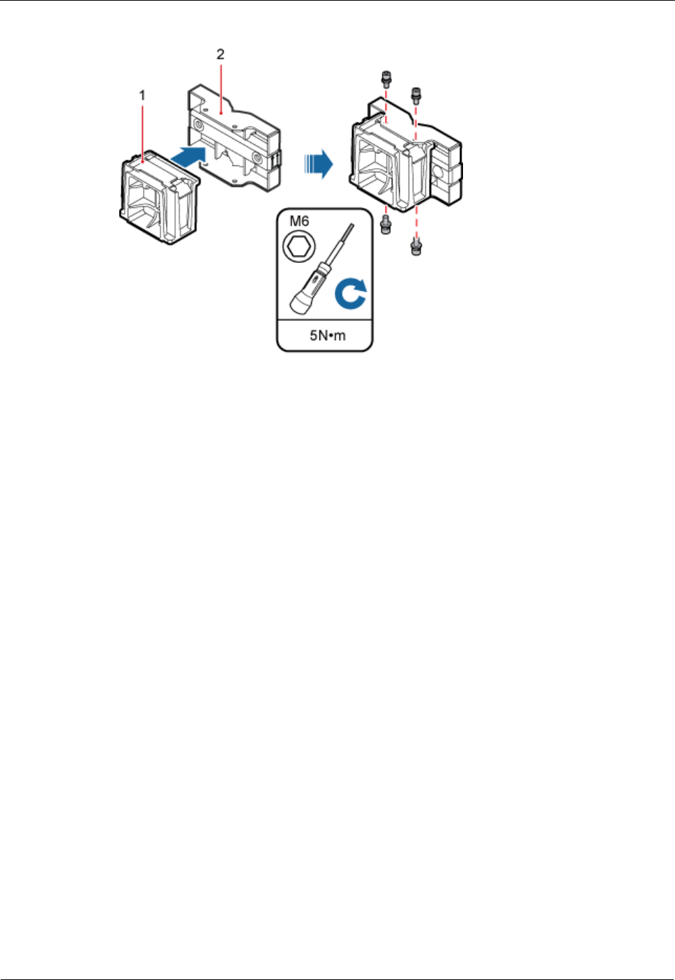
Step 3 Attach the main bracket to the pole installation bracket, and use an inner hexagon screwdriver
to tighten four M6x16 screws to 5 N·m (44.25 lbf·in.) so that the main bracket and pole
installation bracket are firmly secured, as shown in Figure 7-45.
DRH
Installation Guide
7 Installing the DRH
Issue Draft A ()
Huawei Proprietary and Confidential
Copyright © Huawei Technologies Co., Ltd..
68
Figure 7-45 Installing the main bracket
(1) Main bracket
(2) Pole installation bracket
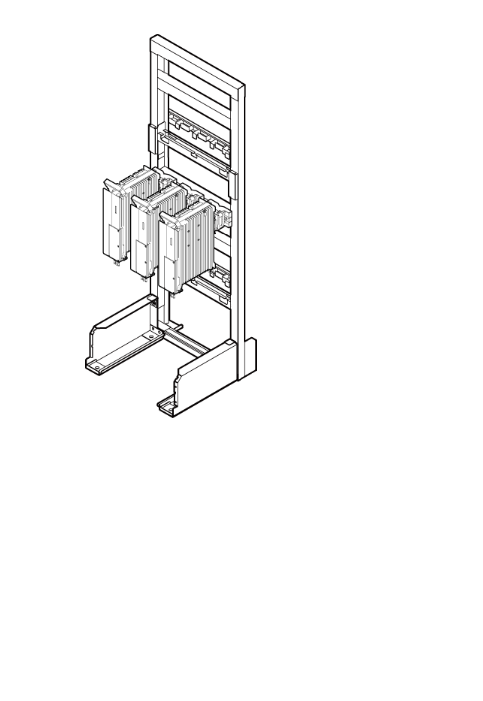
Step 4 Attach the DRH to the main bracket, and then use an inner hexagon screwdriver to tighten the
captive screw into the holes of the attachment plate and main bracket to 5 N·m (44.25 lbf·in.)
so that the attachment plate and main bracket are firmly secured, as shown in Figure 7-46.

DRH
Installation Guide
7 Installing the DRH
Issue Draft A ()
Huawei Proprietary and Confidential
Copyright © Huawei Technologies Co., Ltd..
70
Figure 7-47 Installing DRHs on the lower level
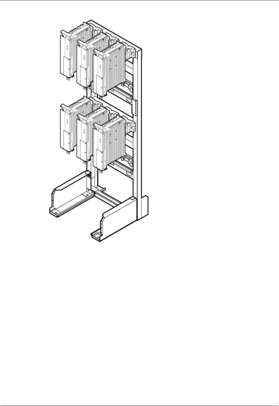
Step 6 Optional: When the ambient temperature is equal to or higher than the lowest operating
temperature of the DRH and at least 10°C (10°F) lower than the highest operating temperature
of the DRH, repeat the preceding steps to install the DRHs on the higher level, as shown in
Figure 7-48.
DRH
Installation Guide
7 Installing the DRH
Issue Draft A ()
Huawei Proprietary and Confidential
Copyright © Huawei Technologies Co., Ltd..
71
Figure 7-48 Installing DRHs on the higher level
----End

DRH
Installation Guide
8 Installing DRH Cables
Issue Draft A ()
Huawei Proprietary and Confidential
Copyright © Huawei Technologies Co., Ltd..
72
8 Installing DRH Cables
This chapter describes the procedure for installing DRH cables.
8.1 Cabling Requirements
Cables must be routed according to the specified cabling requirements to prevent signal
interference.
8.2 Cable Connections
This section describes the cable connections for a single DRH and multiple DRHs.
8.3 Installation Process
This section describes the process of installing DRH cables.
8.4 DRH Cable List
This section describes DRH cable connections.
8.5 Installing a DRH PGND Cable
This section describes the procedure for installing a DRH PGND cable.
8.6 Installing a DRH RF Jumper
This section describes the procedure for installing a DRH RF jumper.
8.7 Installing a DRH Alarm Cable
This section describes the procedure for installing a DRH alarm cable.
8.8 Opening the Cover Plate of a DRH Cabling Cavity
This section describes the procedure for opening the cover plate of a DRH cabling cavity.
8.9 Installing a DRH Power Cable
This section describes the procedure for installing a DRH power cable.
8.10 Installing a CPRI Fiber Optic Cable
This section describes the procedure for installing a CPRI fiber optic cable.
8.11 Closing the Cover Plate of a DRH Cabling Cavity
This section describes the procedure for closing the cover plate of a DRH cabling cavity.

DRH
Installation Guide
8 Installing DRH Cables
Issue Draft A ()
Huawei Proprietary and Confidential
Copyright © Huawei Technologies Co., Ltd..
73
8.1 Cabling Requirements
Cables must be routed according to the specified cabling requirements to prevent signal
interference.
If a cable listed below is not required, skip the routing requirements of the cable.
General Cabling Requirements
Requirements for Bending Radius
The bending radius of the 7/8'' feeder must be more than 250 mm (9.84 in.), and the
bending radius of the 5/4'' feeder must be more than 380 mm (14.96 in.).
The bending radius of the 1/4'' jumper must be more than 35 mm (1.38 in.). The bending
radius of the super-flexible 1/2'' jumper must be more than 50 mm (1.97 in.), and the
bending radius of the ordinary 1/2'' jumper must be more than 127 mm (5 in.).
The bending radius of the power cable or PGND cable must be at least three times the
diameter of the cable.
The bending radius of a fiber optic cable is at least 20 times the diameter of the fiber
optic cable, and the minimum bending radius of the breakout cable at each end of the
fiber optic cable is 30 mm (1.18 in.).
The bending radius of the signal cable must be at least five times the diameter of the
cable.
Requirements for Cable Binding
The same types of cable must be bound together.
Different types of cable must be separately routed with the minimum spacing of 30 mm
(1.18 in.) and cannot be entangled.
The cables must be bound tightly and neatly. The sheaths of the cables must not be
damaged.
Cable ties are installed in the same direction, and those at the same horizontal line must
be in a straight line.
The excess of indoor cable ties is trimmed off, and the excess of outdoor cable ties
allows about 5 mm (0.2 in.), without remaining rough edges.
Labels or nameplates must be attached to both ends, joints, or turns of cables after they
are installed.
Security Requirements
Cables should be placed away from sharp objects or wall burrs. If these positions are
inevitable, protect the cables with protection pipes.
Cables must be routed away from heat sources, or heat-insulation materials are added
between cables and heat sources.
Sufficient slack (recommended for about 0.1 m [0.33 ft]) is provided in cables at turns or
the position close to a device, facilitating cable and device maintenance.
Outdoor Cabling Requirements
Cables routed outdoors must be led through a pipe when they may be damaged.
AC power cables, transmission cables, and cables buried in the ground must be
protected.
DRH
Installation Guide
8 Installing DRH Cables
Issue Draft A ()
Huawei Proprietary and Confidential
Copyright © Huawei Technologies Co., Ltd..
74
If cables at the cabinet bottom need to be routed through a pipe along the ground, lead
the pipe into the cabinet base for about 30 mm (1.18 in.) to 50 mm (1.97 in.), not into the
cabinet. Block the pipe with waterproof tape or silicon gel, and secure the pipe to the
cable hole at the cabinet bottom with metal piece.
If cables at the cabinet bottom need to be routed through a pipe along the metal cable
trough, do not lead the pipe into the cabinet base. The cable trough must be sealed and
routed through the cable hole at the cabinet bottom.
Cables are secured with cable clips.
Cables are routed neatly along the specified cabling direction and secured with cable
clips.
The positions for cable clips are determined onsite. For example, the cable clips for the
7/8" feeder are installed at the spacing of 1.5 m (4.92 ft) to 2 m (6.56 ft) in the same
direction, and the cable clips for the power cables are installed at the spacing of 1.5 m
(4.92 ft) to 2 m (6.56 ft) in the same direction.
Cable clips must be vertical with cables, and the cables in a cable clip must be parallel.
After routing cables neatly and correctly, tighten the screws on cable clips.
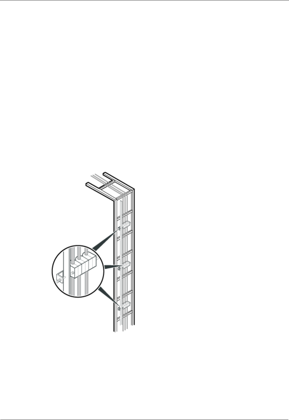
Secure cables on the cable tray, as shown in Figure 8-1.
Figure 8-1 Securing cables on the cable tray
Special Cabling Requirements
Cabling Requirements for Power Cables

DRH
Installation Guide
8 Installing DRH Cables
Issue Draft A ()
Huawei Proprietary and Confidential
Copyright © Huawei Technologies Co., Ltd..
75
Power cables must be installed in the position specified in engineering design
documents.
If the length of power cables is insufficient, replace the cables rather than adding
connectors or soldering joints to lengthen the cables.
Cables must be routed by only qualified and trained personnel before all preparations are
made.
Cables are routed in an untangled and orderly fashion.
Cabling Requirements for PGND Cables
PGND cables for the base station must be connected to the same ground bar.
PGND cables must be buried in the ground or routed indoors. They should not be routed
overhead before they are led into the equipment room.
The exterior of the coaxial wire and the shield layer of the shielded cable must have
proper electrical contact with the metal surface of the equipment to which they are
connected.
PGND cables and signal cables must be installed in an untangled and orderly fashion. A
certain distance must be reserved between them to prevent interference from each other.
Fuses or switches must not be installed on the PGND cables.
Other devices must not be used for electrical connections of the PGND cables.
All the metal parts in the housing of the equipment must be reliably connected to the
ground terminal.
Cabling Requirements for Fiber Optic Cables
Fiber optic cables must be routed by at least three qualified and trained personnel before
all preparations are made.
Fiber optic cables are used within the temperature range of -40°C to 60°C. If the current
temperature is out of the range, make protection measures or route the cables again.
Cables are routed in an untangled and orderly fashion.
Do not bind fiber optic cables at turns.
Do not stretch, step on, or place heavy objects on fiber optic cables. Keep the cables
away from sharp objects.
When fiber optic cables are routed, the excess of the cables must be coiled around
special devices, such as a fiber coiler.
When coiling fiber optic cables, apply even strength. Do not bend the cables with force.
Vacant optical connectors must be covered with dustproof caps.
Fiber optic cables cannot be squeezed by the cabinet door when routed through the
cabinet, as shown in Figure 8-2.
DRH
Installation Guide
8 Installing DRH Cables
Issue Draft A ()
Huawei Proprietary and Confidential
Copyright © Huawei Technologies Co., Ltd..
76
Figure 8-2 CPRI fiber optic cables routed through the cabinet
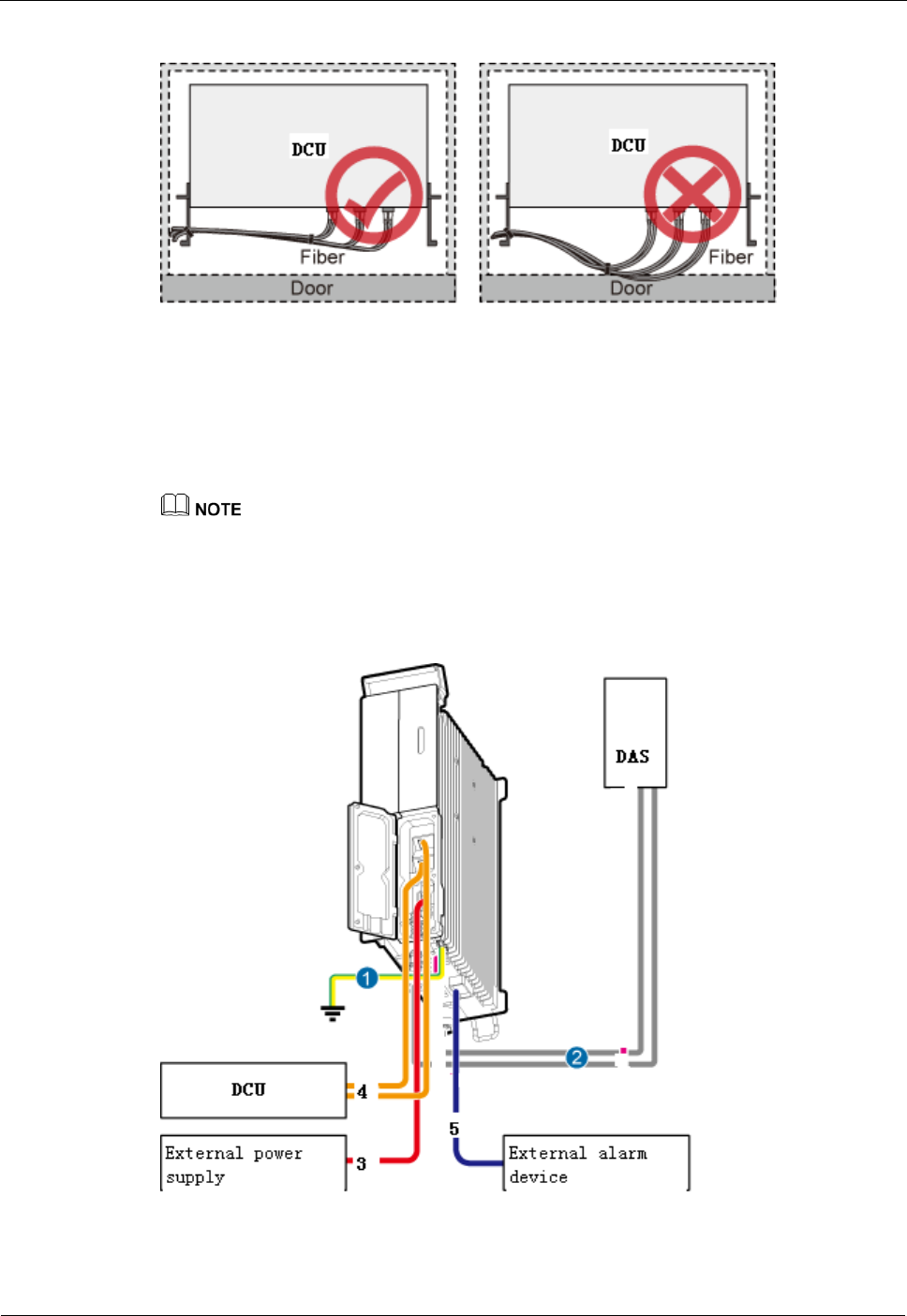
8.2 Cable Connections
This section describes the cable connections for DRHs.
A lower-level DRH obtains power directly from the external power system, but not from an
upper-level DRH using a power cable.
Figure 8-3 shows the cable connections for a single DRH.
Figure 8-3 Cable connections for a single DRH
(1) PGND cable
(2) DRH RF jumper
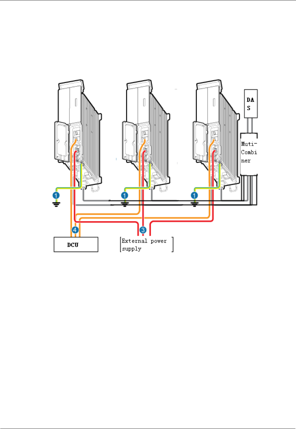
DRH
Installation Guide
8 Installing DRH Cables
Issue Draft A ()
Huawei Proprietary and Confidential
Copyright © Huawei Technologies Co., Ltd..
77
(3) DRH power cable
(4) CPRI fiber optic cable
(5) DRH alarm cable
-
-
Figure 8-4 shows the cable connections for DRHs.
Figure 8-4 Cable connections for DRHs
(1) PGND cable
(2) DRH RF jumper
(3) DRH power cable
(4) CPRI fiber optic cable
-
-
8.3 Installation Process
This section describes the process of installing DRH cables.
Figure 8-5 shows the process of installing DRH cables.
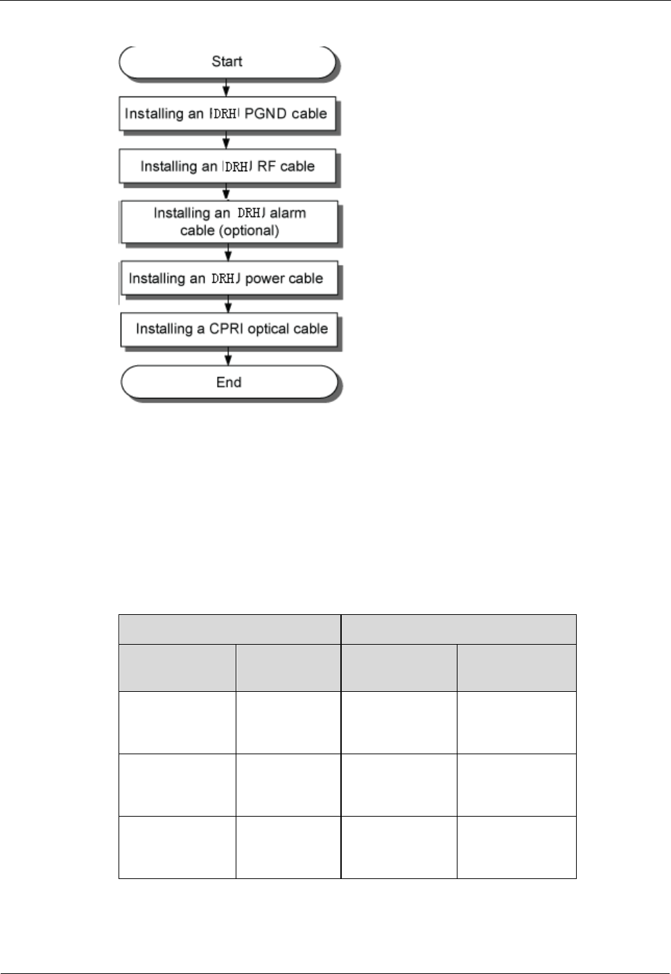
DRH
Installation Guide
8 Installing DRH Cables
Issue Draft A ()
Huawei Proprietary and Confidential
Copyright © Huawei Technologies Co., Ltd..
78
Figure 8-5 Process of installing DRH cables
8.4 DRH Cable List
This section describes DRH cable connections.
Table 8-1 lists DRH cables.
Table 8-1 DRH cables
One End
The Other End
Connector
Installation
Position
Connector
Installation
Position
OT terminal
(M6, 16 mm2 or
0.025 in.2)
Ground
terminal on the
DRH
OT terminal
(M8, 16 mm2 or
0.025 in.2)
Ground terminal
on the ground bar
Tool-less female
connector
(pressfit type)
NEG(-) and
RTN(+) ports
on the DRH
Depending on
the power supply
equipment
External power
equipment
DB15
waterproof male
connector
EXT_ALM
port on the
DRH
Cord end
terminal
External alarm
device

DRH
Installation Guide
8 Installing DRH Cables
Issue Draft A ()
Huawei Proprietary and Confidential
Copyright © Huawei Technologies Co., Ltd..
79
One End
The Other End
Connector
Installation
Position
Connector
Installation
Position
DLC connector
CPRI0 port on
the DRH
DLC connector
CPRI port on a
board in the DCU
or CPRI1 port on
the upper-level
DRH
CPRI1 port on
the DRH
CPRI0 port on
the lower-level
DRH
DIN male
connector
ANT_TX/RX
A or ANT_
RXB port on
the DRH
DIN male
connector
Antenna system
8.5 Installing a DRH PGND Cable
This section describes the procedure for installing a DRH PGND cable.
Context
The cross-sectional area of a DRH PGND cable is 16 mm2 (0.025 in.2). The cable has an M6
OT terminal at one end and an M8 terminal at the other end.
Procedure
Step 1 According to the actual cable route, cut the PGND cable into a proper length to prepare a
DRH PGND cable. Then add an OT terminal at each end of the cable according to the
instructions in Assembling the OT Terminal and the Power Cable.
Step 2 Install the DRH PGND cable.
Connect the M6 OT terminal at one end of the PGND cable to the ground terminal at the
DRH bottom and the M8 OT terminal at the other end to the external ground bar, as shown in
Figure 8-6.
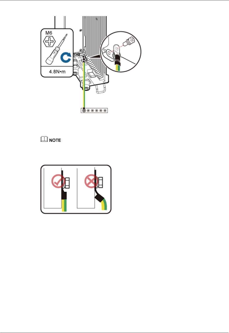
DRH
Installation Guide
8 Installing DRH Cables
Issue Draft A ()
Huawei Proprietary and Confidential
Copyright © Huawei Technologies Co., Ltd..
80
Figure 8-6 Installing a DRH PGND cable
Crimp OT terminals in correct positions, as shown in Figure 8-7.
Figure 8-7 Correct position of an OT terminal
Step 3 Label the installed cables according to the instructions in Attaching a Cable-Tying Label.
----End
8.6 Installing a DRH RF Jumper
This section describes the procedure for installing a DRH RF jumper.
Procedure
Step 1 Connect the DIN male connector at one end of the DRH RF jumper to the ANT port on the
DRH, and use a torque wrench to tighten the connector to 25 N·m (221.27 lbf·in.), as shown
in Figure 8-8.
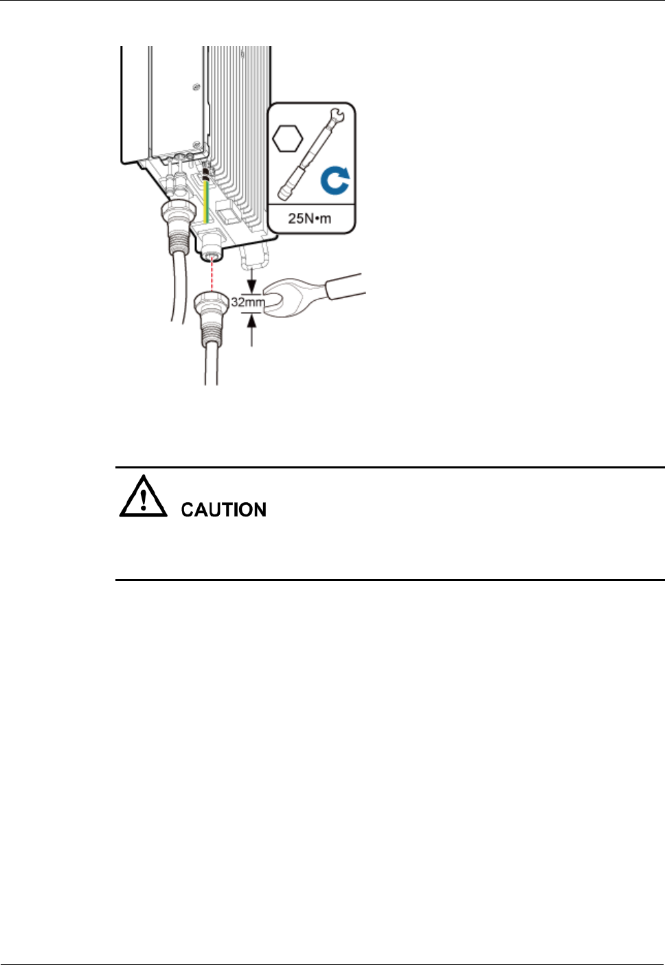
DRH
Installation Guide
8 Installing DRH Cables
Issue Draft A ()
Huawei Proprietary and Confidential
Copyright © Huawei Technologies Co., Ltd..
81
Figure 8-8 Installing a DRH RF jumper
On AC-powered electric railways, such as high speed railways, when leaky cables are
connected to DRHs installed in tunnels, high-voltage-resistance DC blocks must be installed
between DRH RF jumpers and the leaky cables to protect the DRHs against damage.
Step 2 Link the other end of the RF jumper to the external antenna system.
Step 3 Waterproof the connectors of the RF jumper by referring to Figure 8-9.
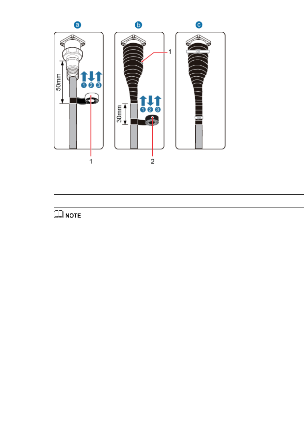
DRH
Installation Guide
8 Installing DRH Cables
Issue Draft A ()
Huawei Proprietary and Confidential
Copyright © Huawei Technologies Co., Ltd..
82
Figure 8-9 Waterproofing a connector of the RF jumper
(1) Waterproof tape
(2) PVC insulation tape
Before wrapping waterproof tape, stretch the tape evenly until the length of the tape becomes twice
its original length.
Do not stretch the PVC insulation tape when wrapping the PVC insulation tape.
Wrap each layer of tape around the connector tightly and neatly, and ensure that each layer of tape
overlaps more than 50% of the preceding layer. Ensure that neighboring layers are stuck to each
other.
Ensure that the adhesive surface of the tape overlaps the lower layer.
When cutting off the cable ties, reserve a redundant length of 3 mm (0.12 in.) to 5 mm (0.2 in.).
1. Wrap three layers of waterproof tape on the connector, first from bottom up, then from
top down, and finally from bottom up. Start wrapping the connector at a position 50 mm
(1.97 in.) away below the bottom of the connector to the top of the connector, first from
bottom up, then from top down, and finally from bottom up. Cut off the redundant tape
after three layers are wrapped. Wrap each layer of tape around the connector tightly.
2. Wrap three layers of PVC insulation tape. Start the wrapping at a position 30 mm (1.18
in.) away below the bottom of the waterproof tape to the top of the connector, first from
bottom up, then from top down, and finally from bottom up. Cut off the redundant tape
after three layers are wrapped. Wrap each layer of tape around the connector tightly.
3. Start binding cable ties to the cable at a position 3 mm (0.12 in.) to 5 mm (0.2 in.) away
from one end of the PVC insulation tape.
Step 4 Check the dustproof caps on antenna connectors. In outdoor scenarios, dustproof caps must be
waterproofed, as shown in Figure 8-10.
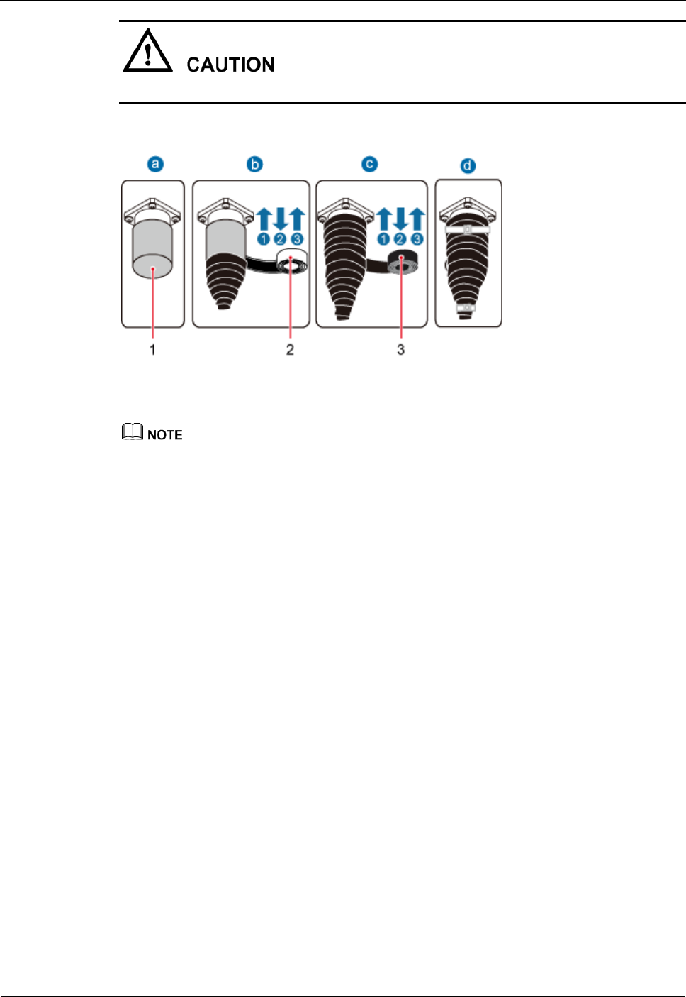
DRH
Installation Guide
8 Installing DRH Cables
Issue Draft A ()
Huawei Proprietary and Confidential
Copyright © Huawei Technologies Co., Ltd..
83
Do not remove dustproof caps from vacant antenna connectors.
Figure 8-10 Waterproofing a dustproof cap
(1) Dustproof cap
(2) Waterproof tape
(3) PVC insulation tape
Before wrapping waterproof tape, stretch the tape evenly until the length of the tape becomes twice
its original length.
Do not stretch the PVC insulation tape when wrapping the PVC insulation tape.
Wrap each layer of tape around the connector tightly and neatly, and ensure that each layer of tape
overlaps more than 50% of the preceding layer. Ensure that neighboring layers are stuck to each
other.
Ensure that the adhesive surface of the tape overlaps the lower layer.
When cutting off the cable ties, reserve a redundant length of 3 mm (0.12 in.) to 5 mm (0.2 in.).
1. Verify that dustproof caps are not removed.
2. Wrap three layers of waterproof tape on the connector, first from bottom up, then from
top down, and finally from bottom up. Wrap each connector with three layers of
waterproof tape, from bottom up, then from top down, and finally from bottom up. Do
not cut the tape until all the three layers of the tape are already wrapped. Cut off the
redundant tape after three layers are wrapped. Wrap each layer of tape around the
connector tightly.
3. Wrap three layers of PVC insulation tape. Wrap each connector with three layers of
waterproof tape, from bottom up, then from top down, and finally from bottom up. Do
not cut the tape until all the three layers of the tape are already wrapped. Cut off the
redundant tape after three layers are wrapped. Wrap each layer of tape around the
connector tightly.
4. Start binding cable ties to the cable at a position 3 mm (0.12 in.) to 5 mm (0.2 in.) away
from one end of the PVC insulation tape.
Step 5 Route the cables according to the instructions in 8.1 Cabling Requirements, and then use
cable ties to bind the cables.
Step 6 Label the installed cables according to the instructions in Attaching a Sign Plate Label.
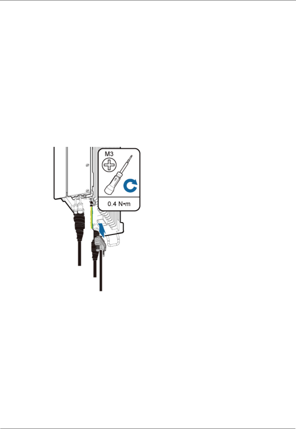
DRH
Installation Guide
8 Installing DRH Cables
Issue Draft A ()
Huawei Proprietary and Confidential
Copyright © Huawei Technologies Co., Ltd..
84
----End
8.7 Installing a DRH Alarm Cable
This section describes the procedure for installing a DRH alarm cable.
Procedure
Step 1 Use an M3 Phillips screwdriver to loosen the screws on the dustproof cap on the EXT_ALM
port and remove the dustproof cap.
Step 2 Connect the waterproof DB15 connector at one end of the DRH alarm cable to the
EXT_ALM port on the DRH, and connect the eight cord end terminals at the other end to
external alarm devices, as shown in Figure 8-11.
Figure 8-11 Installing a DRH alarm cable
Step 3 Use an M3 Phillips screwdriver to tighten the posts on both sides of the waterproof DB15
male connector to 0.4 N·m (3.54 lbf·in.).
Step 4 Route the cables according to the instructions in 8.1 Cabling Requirements, and then use
cable ties to bind the cables.
Step 5 Label the installed cables according to the instructions in Attaching an L-Shaped Label.
----End
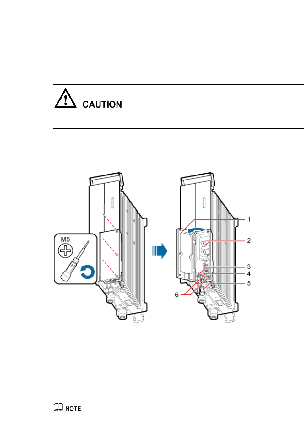
DRH
Installation Guide
8 Installing DRH Cables
Issue Draft A ()
Huawei Proprietary and Confidential
Copyright © Huawei Technologies Co., Ltd..
85
8.8 Opening the Cover Plate of a DRH Cabling Cavity
This section describes the procedure for opening the cover plate of a DRH cabling cavity.
Procedure
Step 1 Wear ESD gloves.
Take proper ESD protection measures, for example, wear ESD gloves, to prevent electrostatic
damage to the boards, modules, or electronic components.
Step 2 Use an M5 Phillips screwdriver to loosen the three screws on the cover plate of the DRH
cabling cavity, and open the cover plate, as shown in Figure 8-12.
Figure 8-12 Opening the cover plate of the DRH cabling cavity
(1) Cover plate
(2) Cabling cavity
(3) Clip
(4) Cable trough for the power
cable
(5) Waterproof
block
(6) Cable trough for the fiber optic
cable
Step 3 Loosen the screws on the clip, and open the clip, as shown Figure 8-13.
Open the clip only for the associated cable.
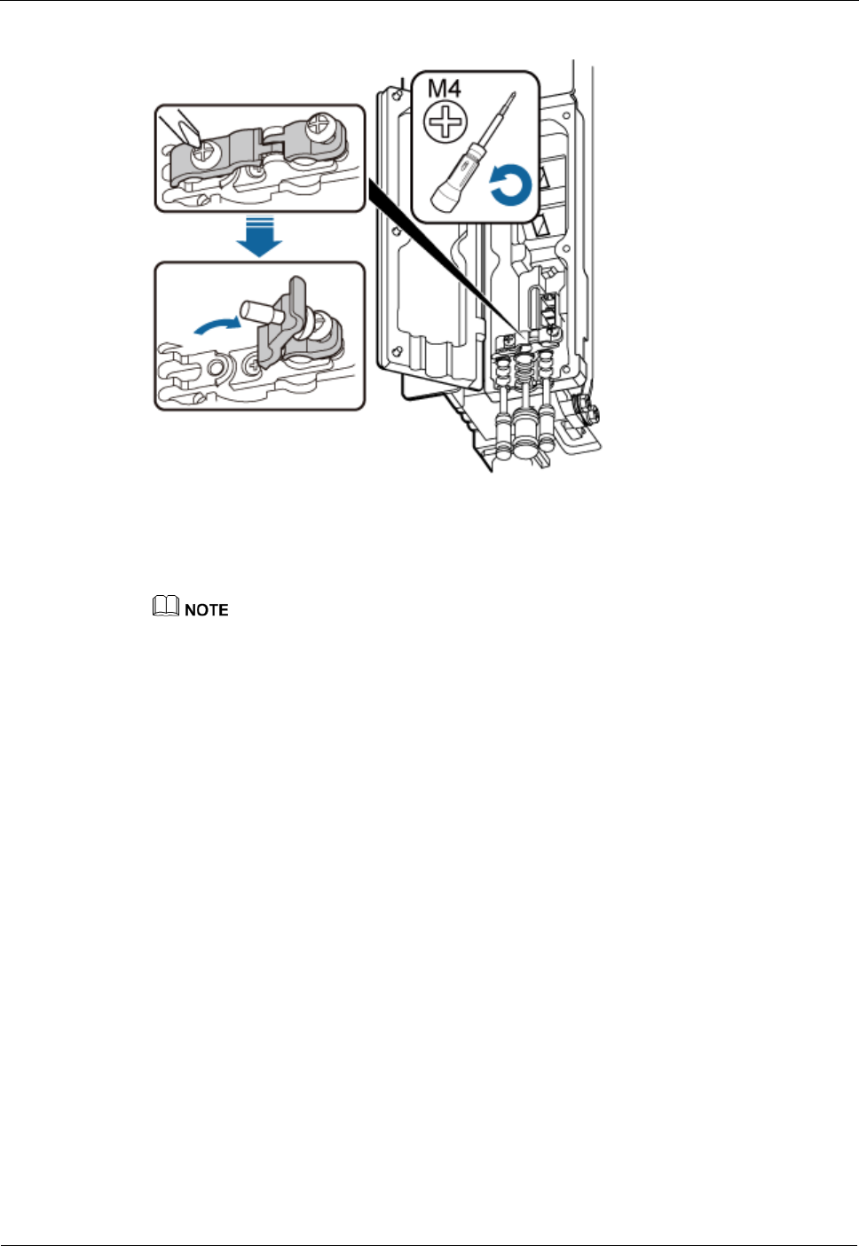
DRH
Installation Guide
8 Installing DRH Cables
Issue Draft A ()
Huawei Proprietary and Confidential
Copyright © Huawei Technologies Co., Ltd..
86
Figure 8-13 Opening clips
Step 4 Remove the waterproof block.
Remove only the waterproof blocks for the cables to be installed.
----End
8.9 Installing a DRH Power Cable
This section describes the procedure for installing a DRH power cable.
Prerequisite
An easy power receptacle (pressfit type) connector is added to the DRH power cable on
the DRH side. For details, see 11.1 Adding a Tool-Less Female Connector (Pressfit Type)
to the DRH Power Cable on the DRH Side.
Add a connector or OT terminals to the DRH power cable on the power device side. For
details, see the DRH Installation Guide.
Context
There are two types of DRH power cables in terms of cross-sectional areas: 3.3 mm2 (0.005
in.2) (12 AWG) complying with North American standards and 4 mm2 (0.006 in.2) complying
with European standards.
Table 8-2 describes the power cable connections.
DRH
Installation Guide
8 Installing DRH Cables
Issue Draft A ()
Huawei Proprietary and Confidential
Copyright © Huawei Technologies Co., Ltd..
87
Table 8-2 Power cable connections
Cabl
e
Powe
r
Devic
e
One End
The Other End
Re
mar
ks
Connector
Instal
latio
n
Positi
on
Connector
Installation
Position
DRH
power
cable
DCD
U-11
B
Tool-less female
connector
(pressfit type)
Power
port
on a
DRH
Tool-less female
connector
(pressfit type)
One of the
LOAD0 to
LOAD5 ports
on the
DCDU-11B
Blac
k
EPU
One of the
DRH0 to
DRH5 ports
on the EPU
When installing the DRH power cable, connect the DRH power cable first to the DRH and
then to the power device. Operations in the reverse sequence may cause damage to the
components and injury of human bodies.
Procedure
Step 1 Connect the tool-less female connector (pressfit type) at one end of the DRH power cable to
the power supply socket on the DRH, as shown in Figure 8-14.
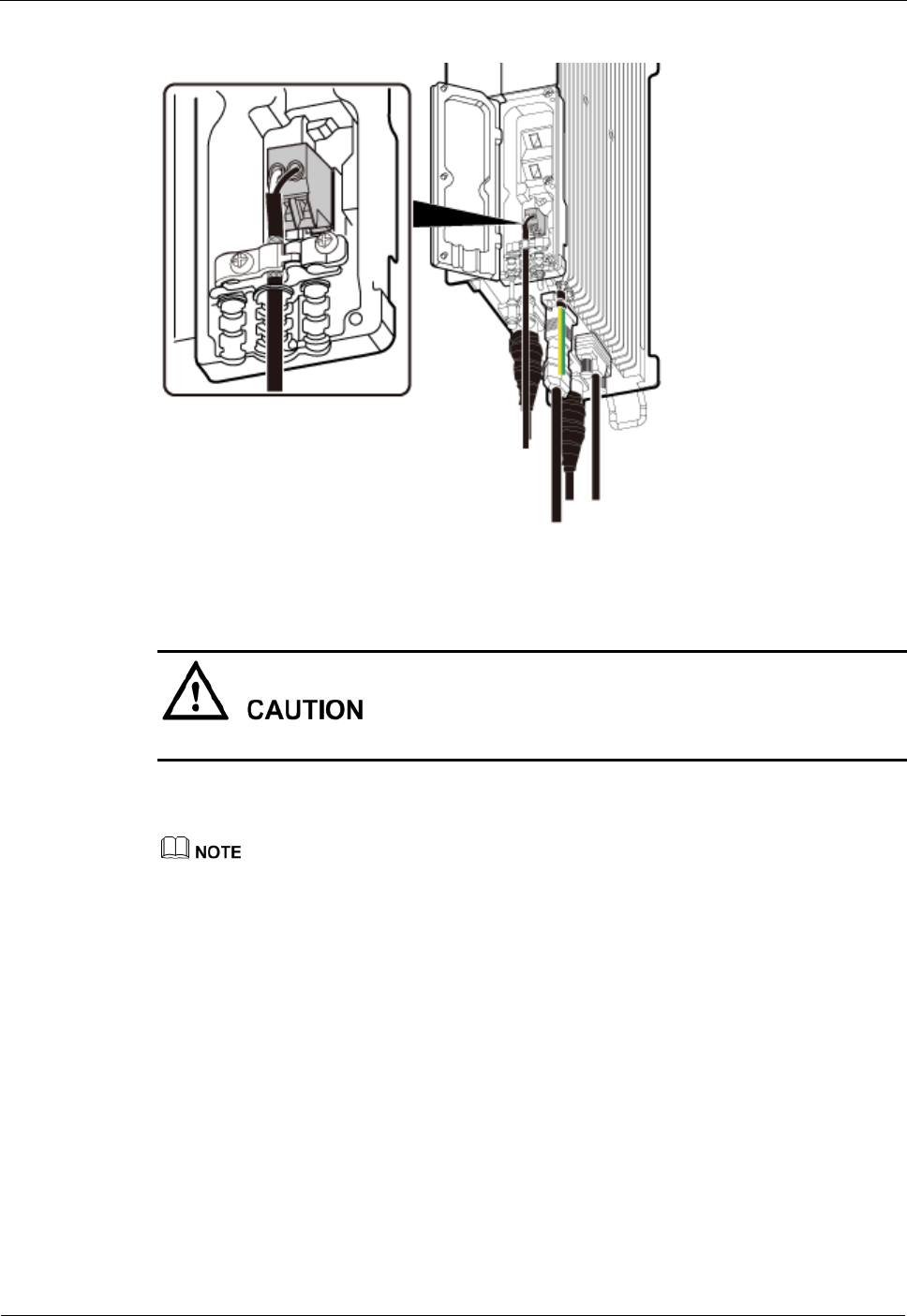
DRH
Installation Guide
8 Installing DRH Cables
Issue Draft A ()
Huawei Proprietary and Confidential
Copyright © Huawei Technologies Co., Ltd..
88
Figure 8-14 Installing a DRH power cable
Ensure that the exposed shield layer of the power cable is properly tightened using the clip.
Step 2 Connect the tool-less female connector (pressfit type) at the other end of the DRH power
cable to the corresponding position on the power device.
A DCDU-11B can supply power to a maximum of six DRHs. The DRH power cables are connected
to the LOAD0 to LOAD5 terminals on the DCDU-11B.
An EPU can supply power to a maximum of six DRHs. The DRH power cables are connected to the
DRH0 to DRH5 ports on the EPU.
When the DRH power cable is connected to the EPU, the blue core wire in the tool-less female
connector (pressfit type) is connected to the left part of a port on the EPU, and the black/brown core
wire is connected to the right part of the port on the EPU.
Step 3 Route the cables according to the instructions in 8.1 Cabling Requirements, and then use
cable ties to bind the cables.
Step 4 Label the installed cables according to the instructions in Attaching a Cable-Tying Label.
----End
8.10 Installing a CPRI Fiber Optic Cable
This section describes the procedure for installing a CPRI fiber optic cable.
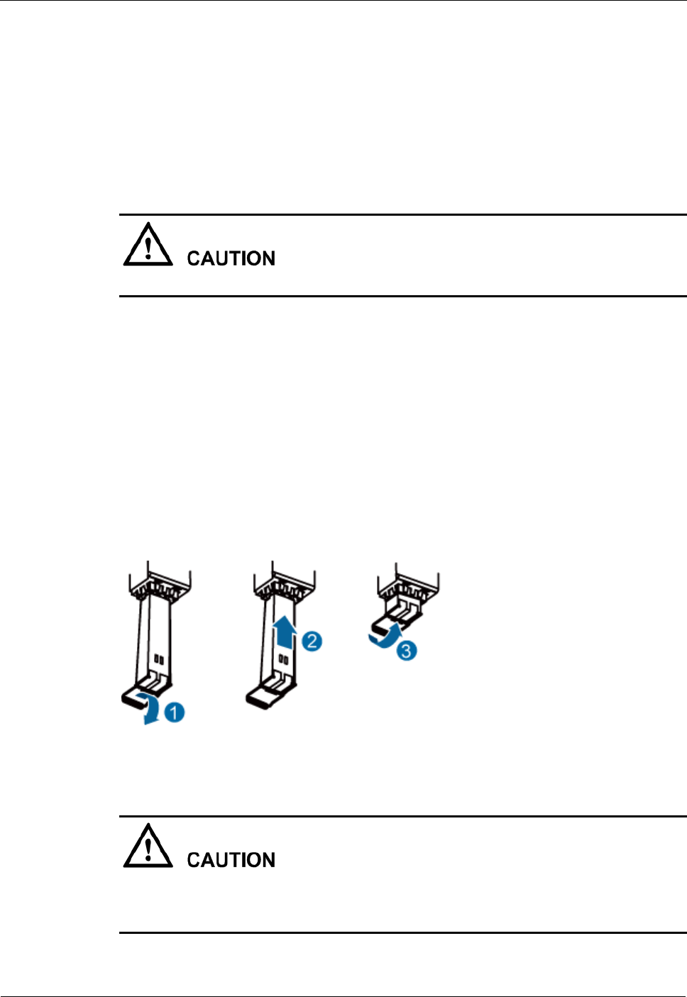
DRH
Installation Guide
8 Installing DRH Cables
Issue Draft A ()
Huawei Proprietary and Confidential
Copyright © Huawei Technologies Co., Ltd..
89
Prerequisite
Before the installation, single-mode optical modules can be distinguished from multi-mode
optical modules in either of the following ways:
SM and MM labels on an optical module: SM indicates a single-mode optical module,
and MM indicates a multi-mode optical module.
Color of the puller on an optical module: Blue indicates a single-mode optical module,
and black or gray indicates a multi-mode optical module.
The optical modules to be installed must match CPRI rates.
Context
A CPRI fiber optic cable transmits CPRI signals between a DCU and a DRH.
For details about CPRI fiber optic cable connections, see section "CPRI Cable
Connections" in the DCU Hardware Description or DRH Hardware Description.
Procedure
Step 1 Lower the pullers of two optical modules, insert one optical module into the CPRI0 port on
the DRH and the other optical module into the CPRI port on the DCU, and raise the pullers,
as shown in Figure 8-15.
Figure 8-15 Installing an optical module
The performance of an optical module that is exposed to the air for more than 20 minutes may
be abnormal. Therefore, you must insert an fiber optic cable into an unpacked optical module
within 20 minutes.
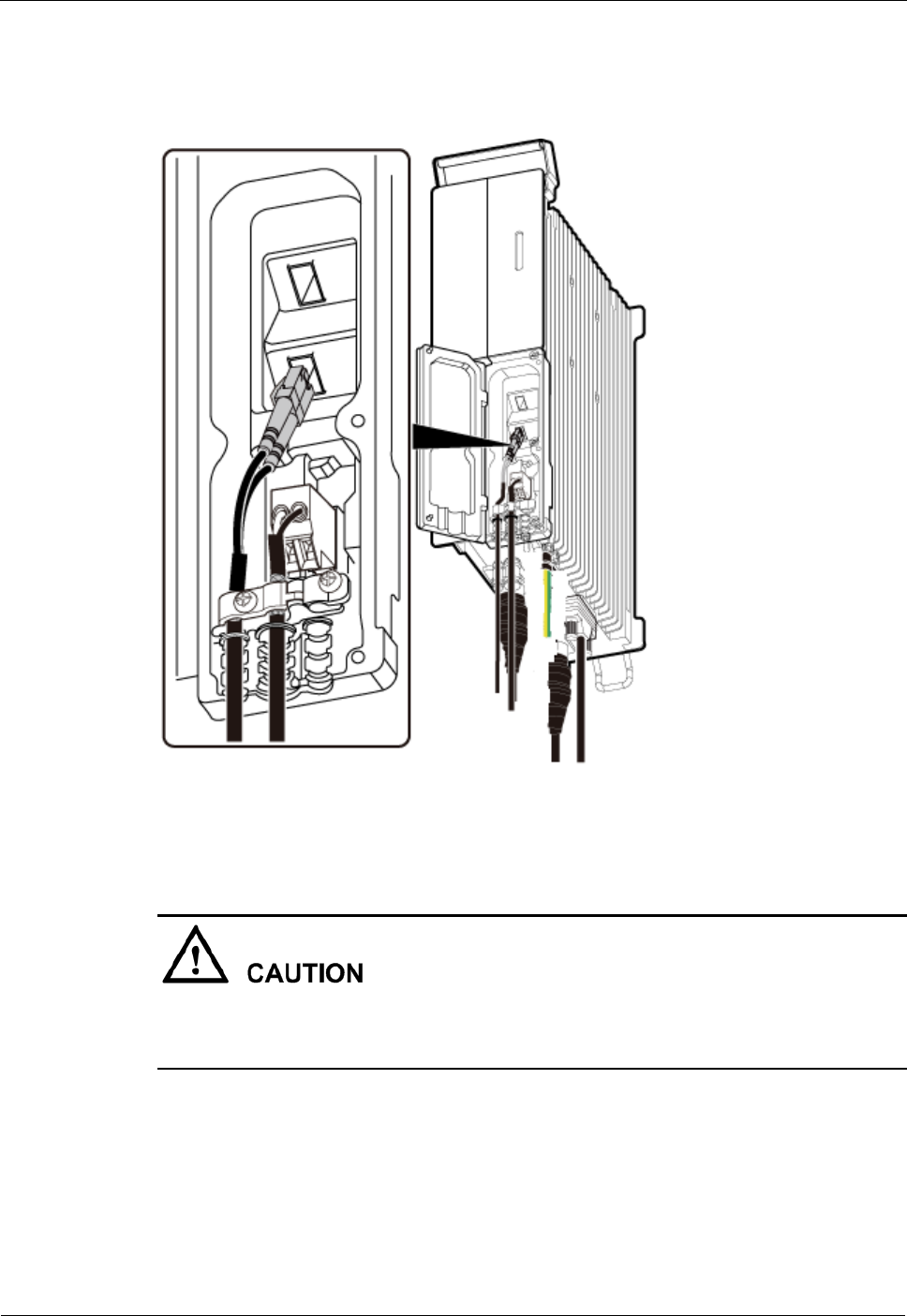
DRH
Installation Guide
8 Installing DRH Cables
Issue Draft A ()
Huawei Proprietary and Confidential
Copyright © Huawei Technologies Co., Ltd..
90
Step 2 Connect the end labeled 1A and 1B of the fiber optic cable to the optical module on the DRH
side, as shown in Figure 8-16.
Figure 8-16 Installing a CPRI fiber optic cable
To avoid any damage to fiber optic cables, the cables connected to the DRH must be
installed according to the installation process. For details about the installation process, see
8.3 Installation Process.
Step 3 Connect the end labeled 2A and 2B of the fiber optic cable to the optical module on the DCU
side.
Step 4 Route the cables according to the instructions in 8.1 Cabling Requirements, and then use
cable ties to bind the cables.
Step 5 Label the installed cables according to the instructions in Attaching an L-Shaped Label.
----End
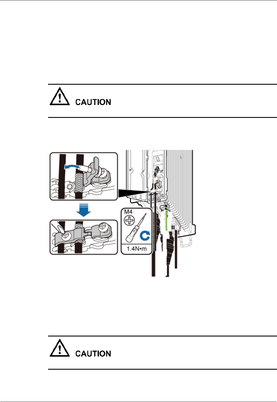
DRH
Installation Guide
8 Installing DRH Cables
Issue Draft A ()
Huawei Proprietary and Confidential
Copyright © Huawei Technologies Co., Ltd..
91
8.11 Closing the Cover Plate of a DRH Cabling Cavity
This section describes the procedure for closing the cover plate of a DRH cabling cavity.
Procedure
Step 1 Close the clips for the installed cables. Use a torque screwdriver to tighten the screws on each
clip to 1.4 N·m (12.39 lbf·in.), as shown in Figure 8-17.
Ensure that the exposed shield layer of the power cable is properly tightened using the clip.
Figure 8-17 Closing clips
Step 2 Insert waterproof blocks into vacant cable troughs in the cabling cavity, as shown in Figure
8-18.
Ensure that cables and waterproof blocks are properly inserted into troughs.
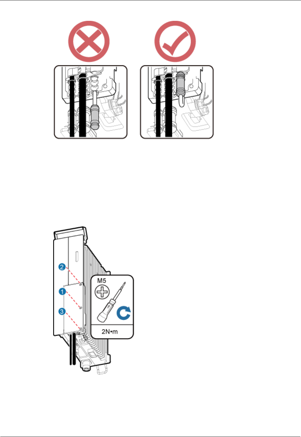
DRH
Installation Guide
8 Installing DRH Cables
Issue Draft A ()
Huawei Proprietary and Confidential
Copyright © Huawei Technologies Co., Ltd..
92
Figure 8-18 Correct placement of waterproof blocks
Step 3 Close the cover plate of the DRH cabling cavity. Use an M5 torque screwdriver to partially
tighten the screws on the cover plate in the sequence shown in Figure 8-19. Then tighten the
screws to 2 N·m (17.7 lbf·in.) in the same sequence.
Figure 8-19 Closing the cover plate of a DRH cabling cavity
Step 4 Take off the ESD gloves, and pack up all the tools.
----End

DRH
Installation Guide
9 Checking the DRH Hardware Installation
Issue Draft A ()
Huawei Proprietary and Confidential
Copyright © Huawei Technologies Co., Ltd..
93
9 Checking the DRH Hardware Installation
After a DRH is installed, check the hardware installation.
Table 9-1 provides the checklist for the DRH hardware installation.
Table 9-1 Checklist for the DRH hardware installation
SN
Item
1
The position for each device conforms to the engineering drawing and meets the
space requirement. Sufficient space is reserved for equipment maintenance.
2
The DRH is securely installed.
3
The cover plate is securely installed on the DRH cabling cavity.
4
Waterproof blocks are securely installed in vacant cable troughs of the DRH
cabling cavity, and the cover plate for the cabling cavity is securely installed. In
addition, vacant RF ports are covered with dustproof caps and the caps are
tightened.
5
There are no connectors or joints on each power cable or PGND cable.
6
The terminals at two ends of each power cable or PGND cable are securely
soldered or crimped.
7
None of power cables and PGND cables can be short-circuited or reversely
connected. In addition, these cables are not damaged or broken.
8
Power cables and PGND cables are separately bound from other cables.
9
The protection grounding of the DRH and the surge protection grounding of the
building share one group of ground conductors.
10
The connectors of each signal cable are intact and securely linked, and these
cables are not damaged or broken.
11
Labels are correct, legible, and complete at both ends of each cable, feeder, and
jumper.
DRH
Installation Guide
10 Powering On a DRH
Issue Draft A ()
Huawei Proprietary and Confidential
Copyright © Huawei Technologies Co., Ltd..
94
10 Powering On a DRH
After all the devices are installed, check the power-on status of a DRH.
After you unpack a DRH, you must power on it within 24 hours. If you power off the DRH
for maintenance, you must restore power to the DRH within 24 hours.
Figure 10-1 shows the DRH power-on check process.
For details about how to power on a DRH, see Powering On a DRH. For details about how to power off
a DRH, see section "Powering-Off the DRH" in DRH Maintenance Guide.
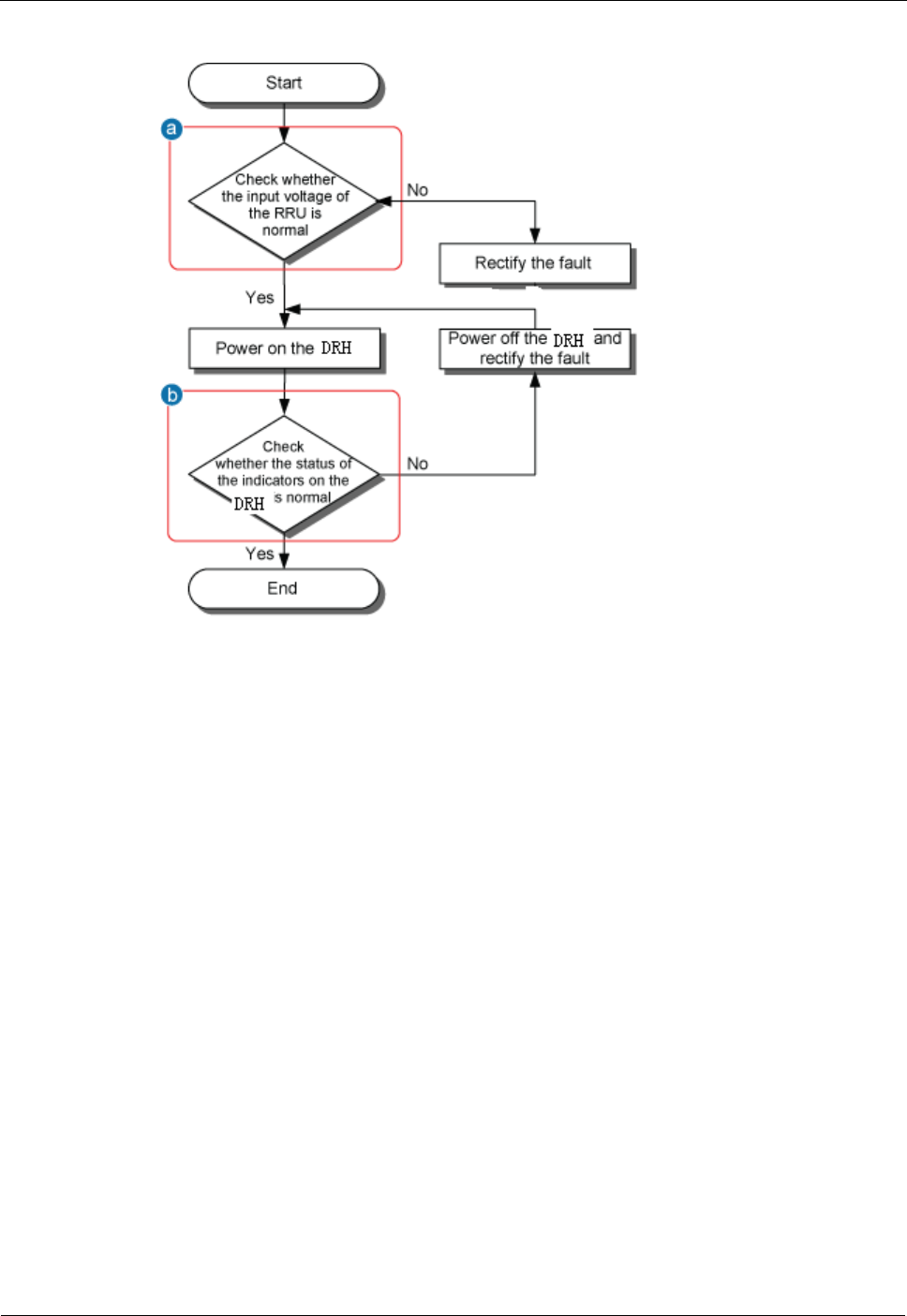
DRH
Installation Guide
10 Powering On a DRH
Issue Draft A ()
Huawei Proprietary and Confidential
Copyright © Huawei Technologies Co., Ltd..
95
Figure 10-1 DRH power-on check process
(a) The normal input voltage of a DRH is -48 V DC. The voltage of the external power
supply should range from -36 V DC to -57 V DC.

DRH
Installation Guide
10 Powering On a DRH
Issue Draft A ()
Huawei Proprietary and Confidential
Copyright © Huawei Technologies Co., Ltd..
96
(b) The RUN indicator on the DRH is on for 1s and off for 1s. The ALM indicator is steady
off.

DRH
Installation Guide
11 Appendix
Issue Draft A ()
Huawei Proprietary and Confidential
Copyright © Huawei Technologies Co., Ltd..
97
11 Appendix
This section describes the procedure for adding an easy power receptacle (pressfit type)
connector.
11.1 Adding a Tool-Less Female Connector (Pressfit Type) to the DRH Power Cable on the
DRH Side
This section describes the procedure for adding a tool-less female connector (pressfit type) to
the DRH power cable on the DRH side.
11.1 Adding a Tool-Less Female Connector (Pressfit Type)
to the DRH Power Cable on the DRH Side
This section describes the procedure for adding a tool-less female connector (pressfit type) to
the DRH power cable on the DRH side.
Context
Figure 11-1 shows the cable diagram on labels.

DRH
Installation Guide
11 Appendix
Issue Draft A ()
Huawei Proprietary and Confidential
Copyright © Huawei Technologies Co., Ltd..
98
Figure 11-1 Cable diagram on labels
(1) Cable diagram on labels
Procedure
Step 1 Determine the length of the power cable for different operations based on the labels, as shown
in Figure 11-2.
Figure 11-2 Determining the length of the power cable
Step 2 Strip the specified length of the sheath off the power cable, as shown in Figure 11-3.
Figure 11-3 Stripping the specified length of sheath
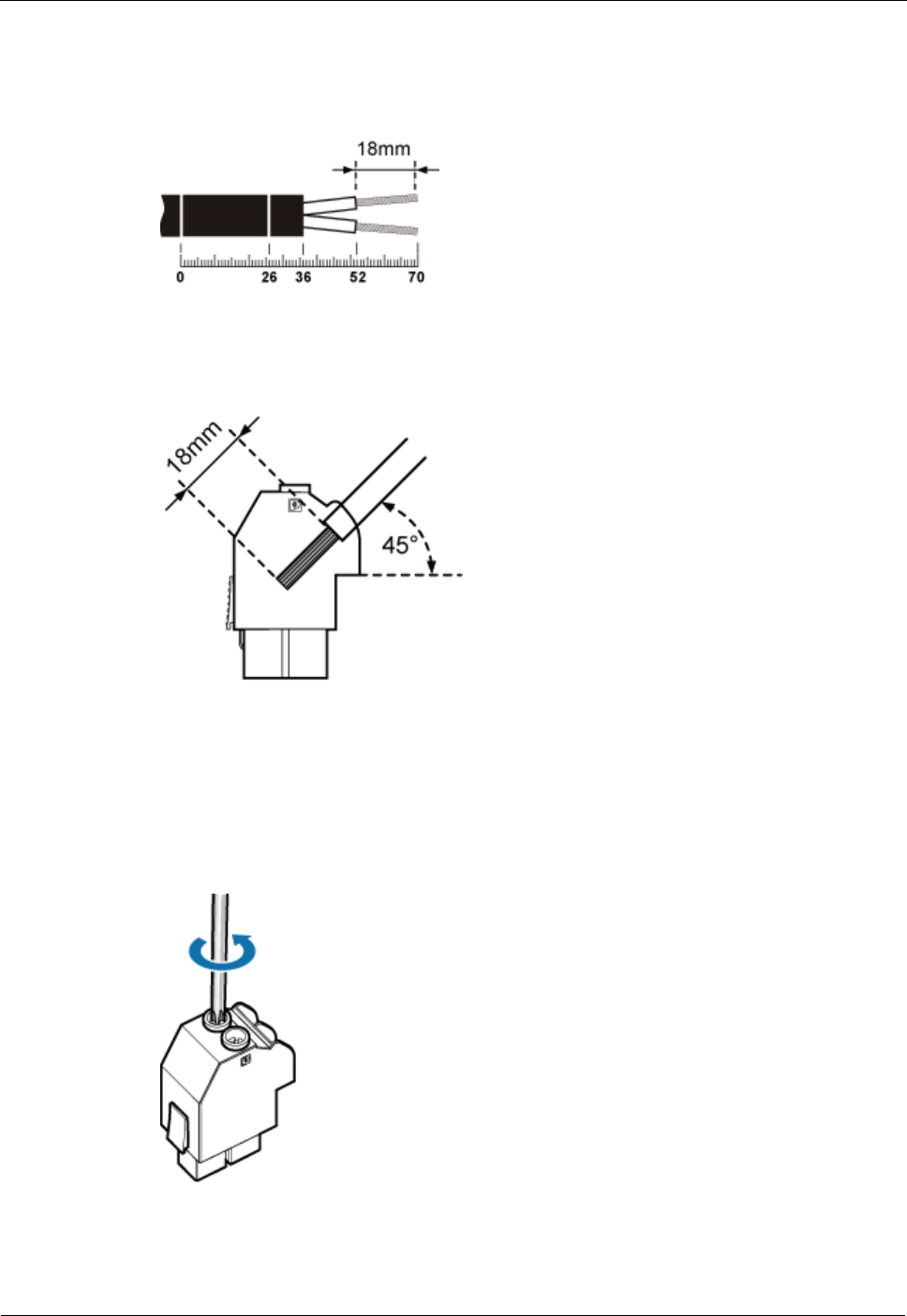
DRH
Installation Guide
11 Appendix
Issue Draft A ()
Huawei Proprietary and Confidential
Copyright © Huawei Technologies Co., Ltd..
99
Step 3 Strip a specified length of sheath off each core wire. The length must be consistent with the
length of the notch in the tool-less female connector (pressfit type), as shown in Figure 11-4.
Figure 11-4 Stripping the sheath off each core wire
Figure 11-5 Matched length
Step 4 Add a tool-less female connector (pressfit type) to two core wires.
1. Tighten the screws using a Phillips screwdriver, as shown in Figure 11-6.
Figure 11-6 Tightening screws
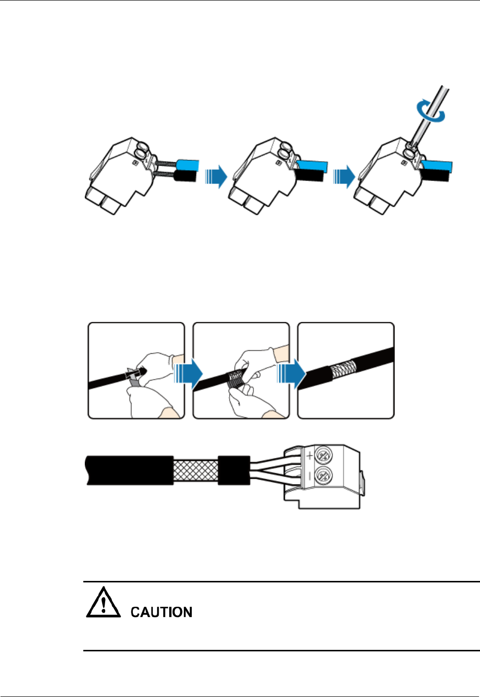
DRH
Installation Guide
11 Appendix
Issue Draft A ()
Huawei Proprietary and Confidential
Copyright © Huawei Technologies Co., Ltd..
100
2. Connect the blue core wire labeled NEG(-) to the - port and the black/brown core wire
labeled RTN(+) to the + port on the tool-less female connector (pressfit type), and then
tighten the screws using a Phillips screwdriver, as shown in Figure 11-7.
Figure 11-7 Adding a tool-less female connector (pressfit type) to two core wires
Step 5 Strip the specified length of the sheath off the power cable to expose the intact shield layer, as
shown in Figure 11-8.
Figure 11-8 Stripping the sheath off the power cable
Each core wire is exposed outside the tool-less female connector (pressfit type) for 1.5 mm
(0.059 [in.]), as shown in Figure 11-9.
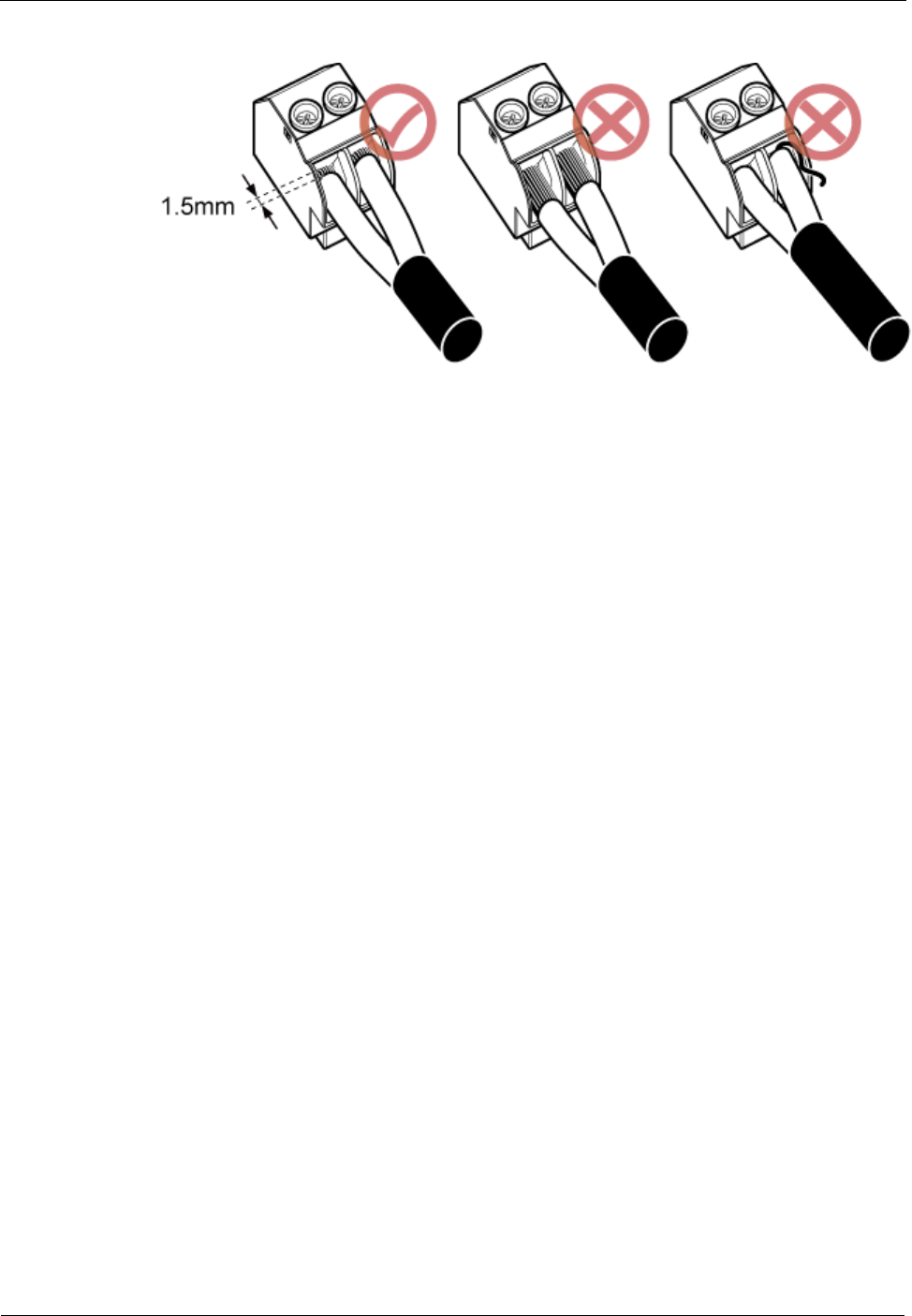
DRH
Installation Guide
11 Appendix
Issue Draft A ()
Huawei Proprietary and Confidential
Copyright © Huawei Technologies Co., Ltd..
101
Figure 11-9 Inserting core wires into the tool-less female connector (pressfit type)
----End