Huawei Technologies EAN3710A eLTE-IoT AirNode User Manual
Huawei Technologies Co.,Ltd eLTE-IoT AirNode Users Manual
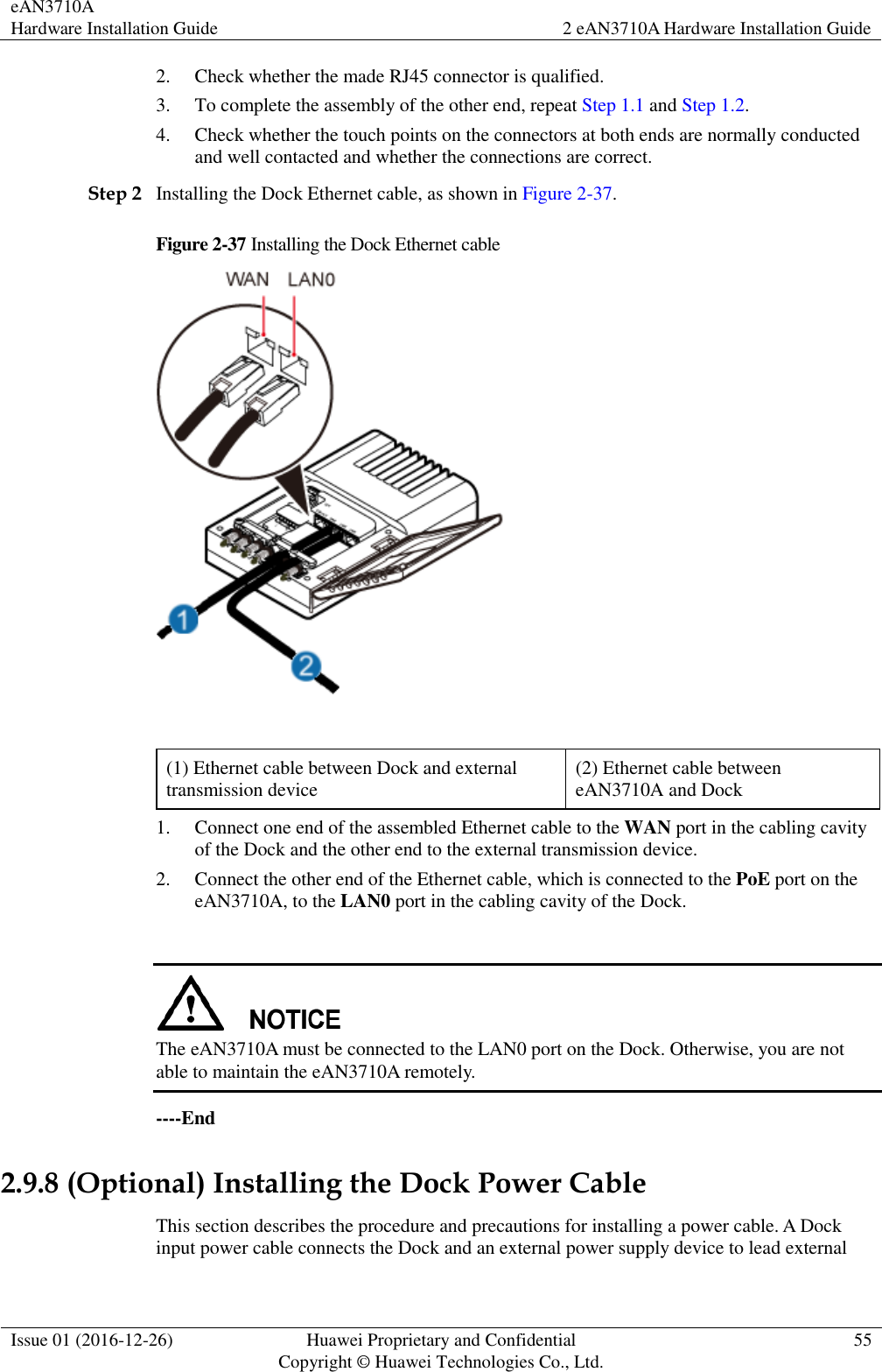
UserManual.wiki
>
Huawei Technologies
>
EAN3710A User Manual
>
Users Manual
Contents
1.
Users Manual
2.
Safety Information
Users Manual
Navigation menu
Upload a User Manual
Namespaces
Wiki Guide
HTML
PDF
Info
Views
User Manual
Discussion / Help
Navigation


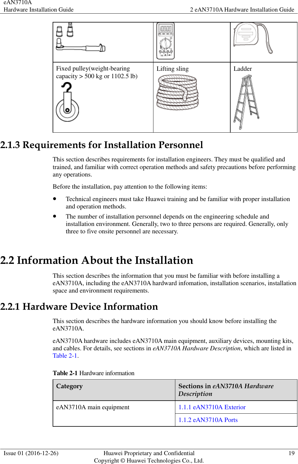
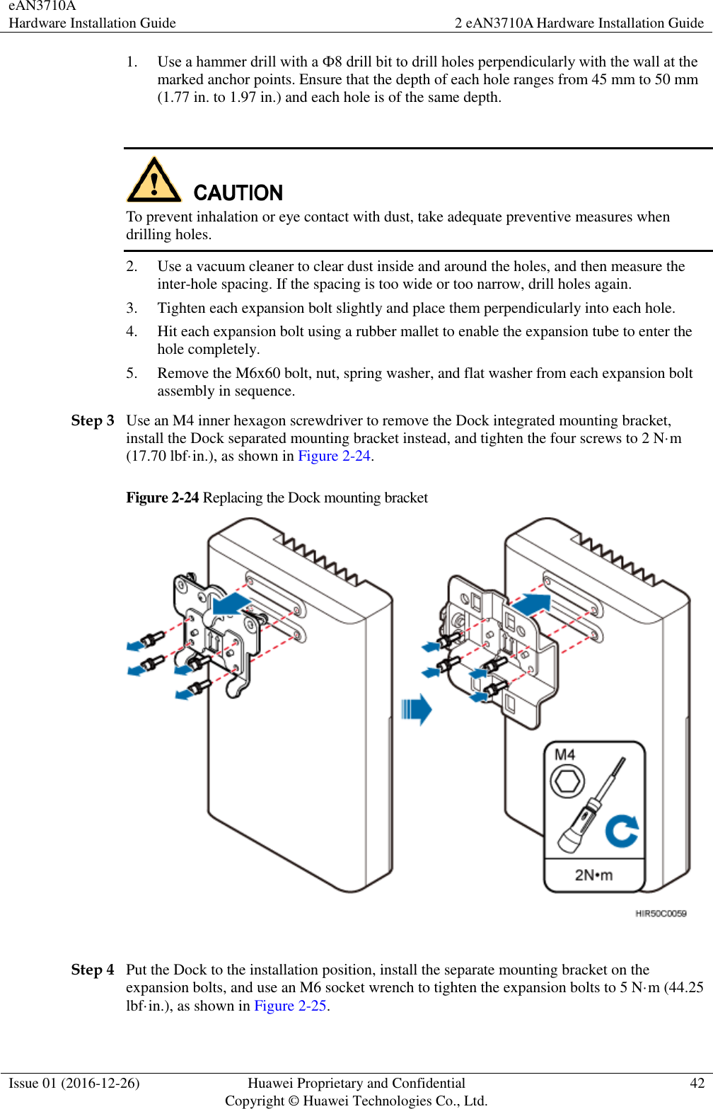
![eAN3710A Hardware Installation Guide 2 eAN3710A Hardware Installation Guide Issue 01 (2016-12-26) Huawei Proprietary and Confidential Copyright © Huawei Technologies Co., Ltd. 18 Hammer drill (a φ12 bit) ESD gloves Vacuum cleaner Heat gun Phillips screwdriver (M3 to M6) Flat-head screwdriver (M3 to M6) Rubber mallet COAX crimping tool Wire stripper Power cable crimping tool RJ45 crimping tool Diagonal plier Utility knife Level Network cable tester Adjustable wrench (size ≥ 32 mm [1.26 in.]) Torque wrench Size: 16 mm (0.63 in.) and 22 mm (0.87 in.) Combination wrench Size: 16 mm (0.63 in.) and 22 mm (0.87 in.) Torque screwdriver 3mm or 5mm (M3 to M6) (M3 to M6) Marker (diameter ≤ 10 mm [0.39 in.]) Torque socket (M6 or M10) Multimeter Measuring tape](https://usermanual.wiki/Huawei-Technologies/EAN3710A.Users-Manual/User-Guide-3368859-Page-20.png)
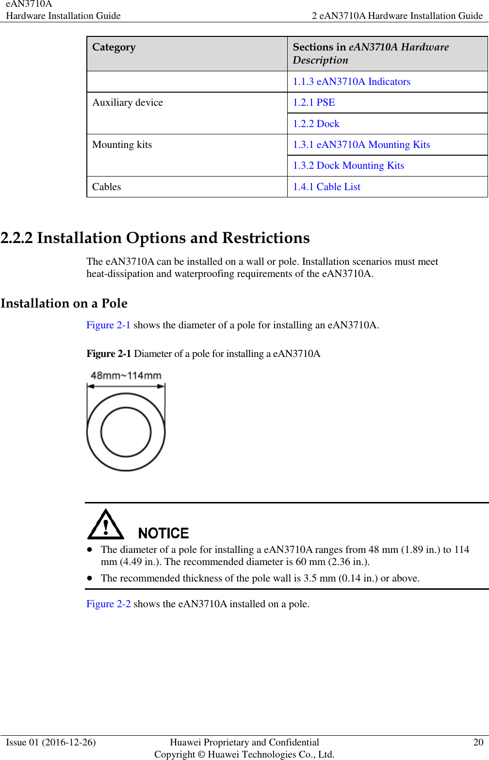

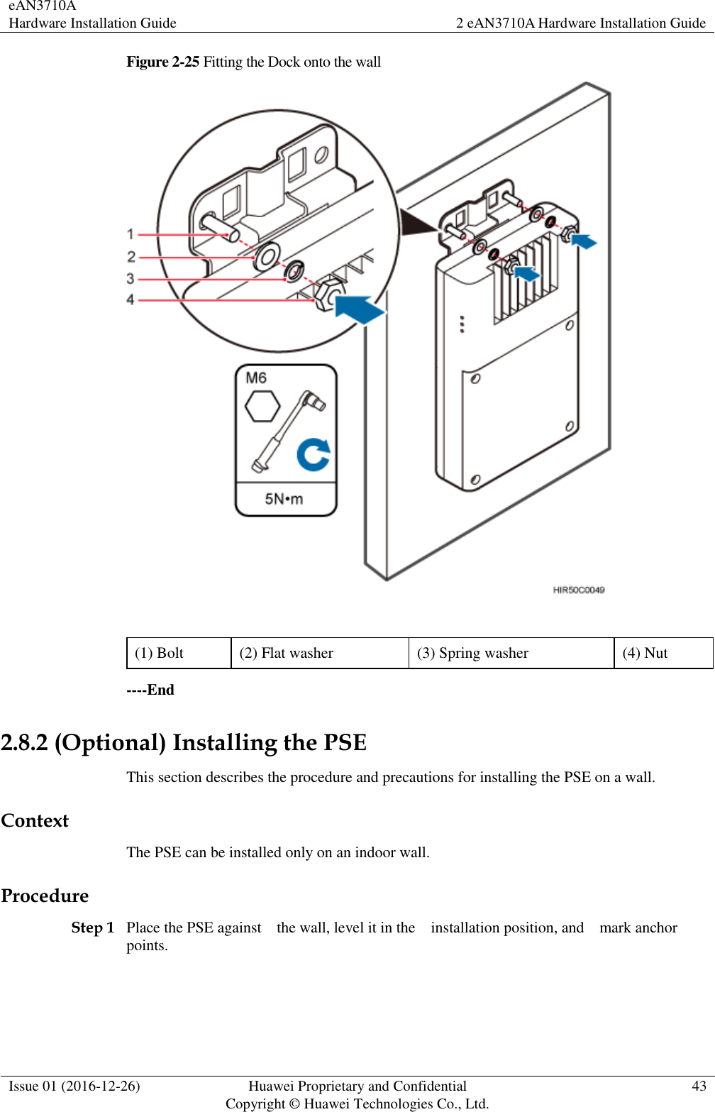
![eAN3710A Hardware Installation Guide 2 eAN3710A Hardware Installation Guide Issue 01 (2016-12-26) Huawei Proprietary and Confidential Copyright © Huawei Technologies Co., Ltd. 46 Cables must be bound tightly and neatly. The sheaths of cables must not be damaged. Cable ties must face the same direction, and those at the same horizontal line must be in a straight line. The excess of indoor cable ties must be cut off. The excess of 5 mm (0.197 in.) of outdoor cable ties should be reserved, and the cut surfaces must be smooth without sharp edges. After cables are installed, labels or nameplates must be attached to the cables at their ends, curves, and interconnection positions. Security requirements When laying out cables, avoid sharp objects, for example sharp edges on the wall. If necessary, use tubes to protect the cables. When laying out cables, keep cables away from heat sources, or use heat insulation materials to insulate the cables from the heat sources. Reserve a proper distance (0.1 m [3.937 in.] is recommended) between equipment and cables especially at the cable curves to protect the cables and equipment. Indoor cabling requirements Route each cable into the room through the feeder window. Reserve drip loops for all cables outside the feeder window before routing them into the room. Ensure that the radiuses of the drip loops are greater than or equal to the minimum bending radiuses of the cables. When routing a cable into the room, ensure that a person is assisting you in the room. Apply waterproof treatment to the feeder window. Outdoor Cabling Requirements Protect outdoor cables against potential damage. For example, thread the cables through tubes. Cables to be protected include AC power cables, transmission cables, and cables laid out underground. Use cable clips to secure cables outdoors. Arrange cables neatly along the routing direction and use cable clips to secure the cables. Determine the positions where the clips are installed according to the actual situation. For example, 7/8" feeders are secured with clips at an interval of 1.5 m (4.92 ft) to 2 m (6.56 ft), and CPRI fiber optic cables and power cables are secured with clips at an interval of 1 m (3.28 ft) to 1.5 m (4.92 ft). Ensure that the clips are evenly spaced and in the same direction. When fastening cables with a clip, ensure that the cables are aligned neatly and are routed through the holes in the clip. Do not stretch the cables too tightly. When using clips to secure cables, tighten the screws on the clips after all cables are arranged and laid out. Special Cabling Requirements Cabling of PGND cables PGND cables for a base station must be connected to the same ground bar. PGND cables must be buried in the ground or routed indoors.](https://usermanual.wiki/Huawei-Technologies/EAN3710A.Users-Manual/User-Guide-3368859-Page-48.png)