Huawei Technologies EAN3710A eLTE-IoT AirNode User Manual
Huawei Technologies Co.,Ltd eLTE-IoT AirNode Users Manual
Contents
- 1. Users Manual
- 2. Safety Information
Users Manual

eAN3710A
V100R001C00
Hardware Installation Guide
Issue
01
Date
2016-12-26
HUAWEI TECHNOLOGIES CO., LTD.

Issue 01 (2016-12-26)
Huawei Proprietary and Confidential
Copyright © Huawei Technologies Co., Ltd.
i
Copyright © Huawei Technologies Co., Ltd. 2016. All rights reserved.
No part of this document may be reproduced or transmitted in any form or by any means without prior
written consent of Huawei Technologies Co., Ltd.
Trademarks and Permissions
and other Huawei trademarks are trademarks of Huawei Technologies Co., Ltd.
All other trademarks and trade names mentioned in this document are the property of their respective
holders.
Notice
The purchased products, services and features are stipulated by the contract made between Huawei and
the customer. All or part of the products, services and features described in this document may not be
within the purchase scope or the usage scope. Unless otherwise specified in the contract, all statements,
information, and recommendations in this document are provided "AS IS" without warranties, guarantees or
representations of any kind, either express or implied.
The information in this document is subject to change without notice. Every effort has been made in the
preparation of this document to ensure accuracy of the contents, but all statements, information, and
recommendations in this document do not constitute a warranty of any kind, express or implied.
Huawei Technologies Co., Ltd.
Address:
Huawei Industrial Base
Bantian, Longgang
Shenzhen 518129
People's Republic of China
Website:
http://www.huawei.com
Email:
support@huawei.com

eAN3710A
Hardware Installation Guide
1 eAN3710A Hardware Description
Issue 01 (2016-12-26)
Huawei Proprietary and Confidential
Copyright © Huawei Technologies Co., Ltd.
1
1 eAN3710A Hardware Description
About This Chapter
Overview
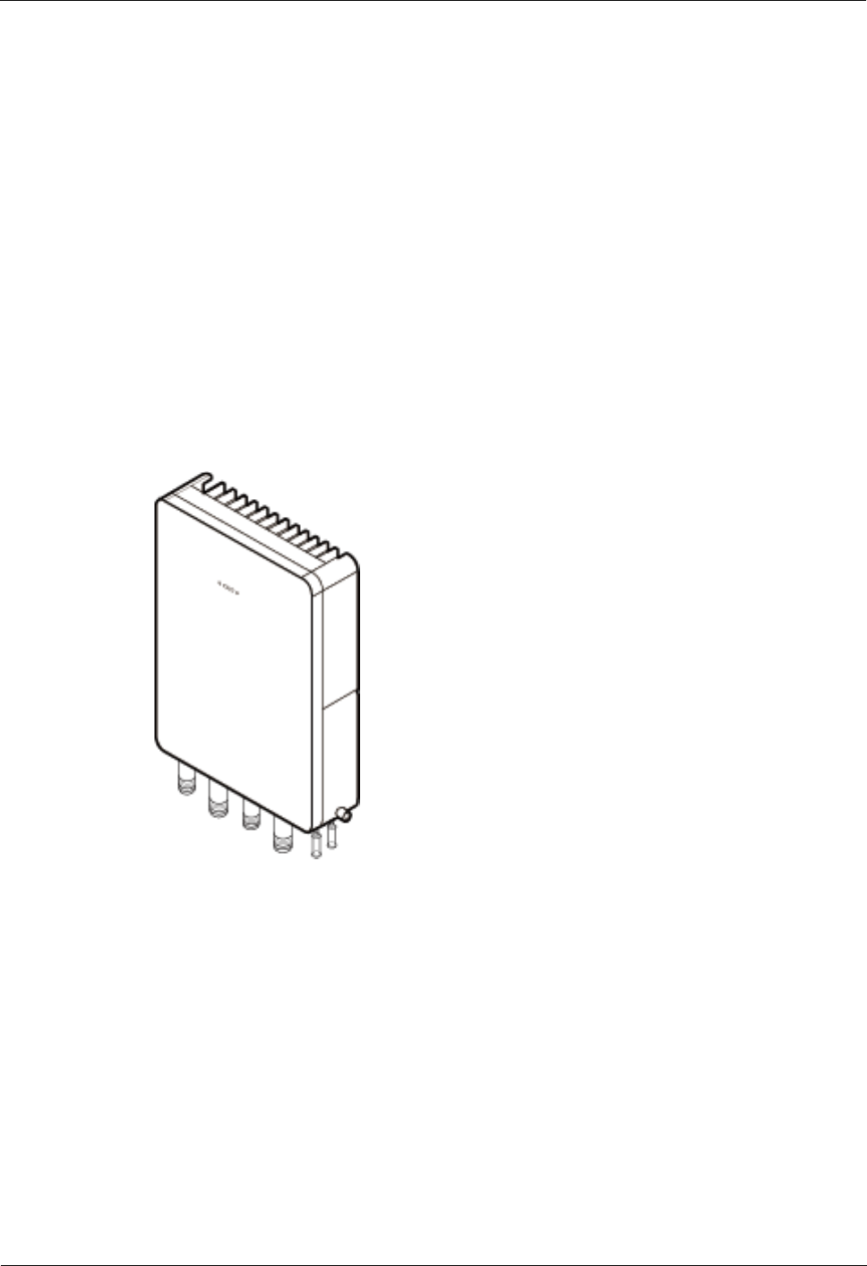
This section describes the exterior, ports, indicators and cables of eAN3710A.
Product Version
Unless otherwise stated, "eNodeB", "Pico", "eAN", and "AirNode" in this document refer to the 3710
series AirNode.
The 3710 series AirNode is a base station that provides communications services in Huawei
eLTE-IoT solution. The following table lists the product name and product version related to
the 3710 series AirNode.
Product Name
Product Version
eAN3710A
V100R001C00
Intended Audience
This document is intended for:
Installation engineers
Site maintenance engineers
System engineers
Organization
1.1 eAN3710A Equipment
This section describes the exterior, ports and indicators of eAN3710A.
1.2 Auxiliary Devices
The PSE or Dock supplies power to a eAN3710A through an Ethernet cable in PoE mode.
eAN3710A
Hardware Installation Guide
1 eAN3710A Hardware Description
Issue 01 (2016-12-26)
Huawei Proprietary and Confidential
Copyright © Huawei Technologies Co., Ltd.
2
1.3 Mounting Kits
This section describes the mounting brackets for installing a eAN3710A.
1.4 Cables
This section describes eAN3710A cables.
1.1 eAN3710A Equipment
This section describes the exterior, ports and indicators of eAN3710A.
1.1.1 eAN3710A Exterior
This section describes the exterior and dimensions of a eAN3710A.
Figure 1-1 shows the exteriors of the eAN3710A.
Figure 1-1 eAN3710A exterior
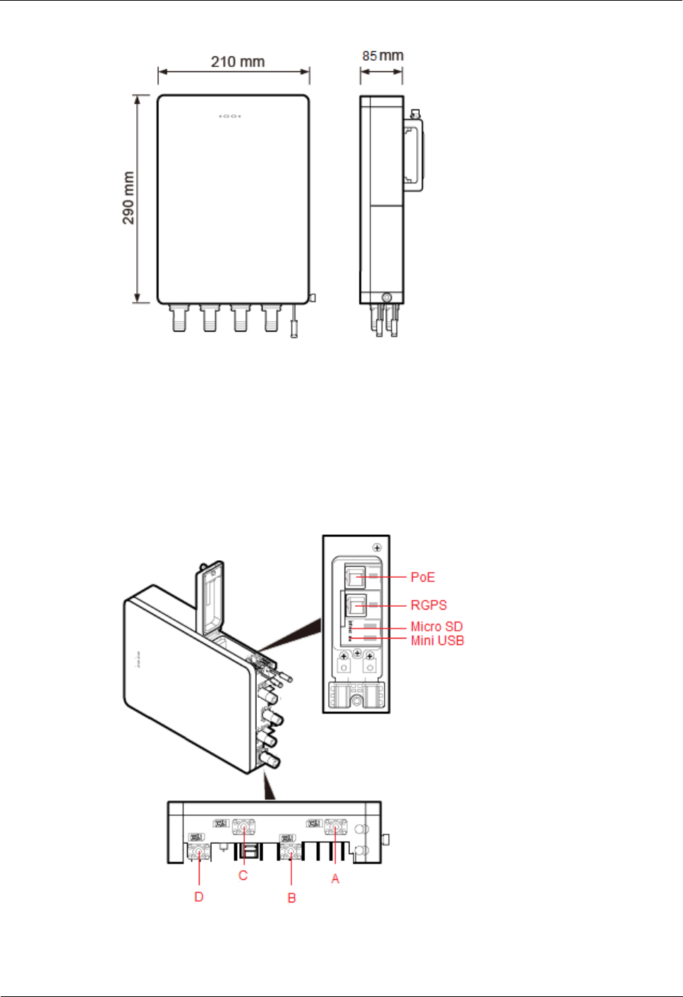
Figure 1-2 shows the dimensions of eAN3710A.
eAN3710A
Hardware Installation Guide
1 eAN3710A Hardware Description
Issue 01 (2016-12-26)
Huawei Proprietary and Confidential
Copyright © Huawei Technologies Co., Ltd.
3
Figure 1-2 eAN3710A dimensions
1.1.2 eAN3710A Ports
This section describes ports on the eAN3710A panels. An eAN3710A has a bottom panel, and
cabling cavity panel.
Figure 1-3 shows the ports on the eAN3710A panels.
Figure 1-3 Ports on the eAN3710A panels
Table 1-1 describes ports on the eAN3710A cabling cavity panels.
eAN3710A
Hardware Installation Guide
1 eAN3710A Hardware Description
Issue 01 (2016-12-26)
Huawei Proprietary and Confidential
Copyright © Huawei Technologies Co., Ltd.
4
Table 1-1 Ports on the eAN3710A cabling cavity panels
Port/Slot
Description
PoE
Used for power supply and data
transmission.
RGPS
Used for clock synchronization.
Micro SD
Used for housing a micro SD card. This slot
is used in the case of deployment.
Mini USB
Used for testing a port.
There are four RF ports on an eAN3710A bottom panel, Table 1-2 lists the TX/RX frequency
band supported by the RF ports.
Table 1-2 TX/RX frequency band supported by the RF ports
RF ports
TX/RX frequency band
A
863 MHz to 870 MHz (Europe)
902 MHz to 928 MHz (Latin America)
B
C
470 MHz to 510 MHz (China)
D
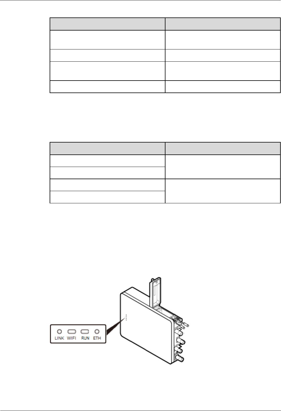
1.1.3 eAN3710A Indicators
This section describes the eAN3710A indicators.
Figure 1-4 shows the position of the eAN3710A indicators.
Figure 1-4 Position of the eAN3710A indicators
Table 1-3 describes the eAN3710A indicators.
eAN3710A
Hardware Installation Guide
1 eAN3710A Hardware Description
Issue 01 (2016-12-26)
Huawei Proprietary and Confidential
Copyright © Huawei Technologies Co., Ltd.
5
Table 1-3 eAN3710A indicators
Indicators
Description
LINK
Link status
WIFI
Wi-Fi processing unit status
RUN
Cellular processing unit status
ETH
ETH status
1.2 Auxiliary Devices
The PSE or Dock supplies power to a eAN3710A through an Ethernet cable in PoE mode.
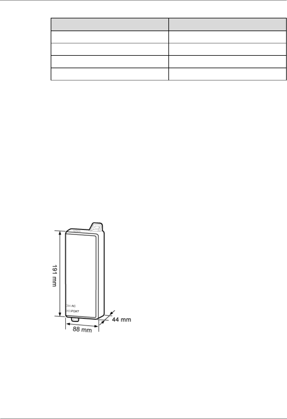
1.2.1 PSE
This section describes the appearance, dimensions, ports, and indicators of the PSE, and the
PSE specifications.
Appearance and Dimensions
Figure 1-5 shows the appearance and dimensions of the PSE.
Figure 1-5 Appearance and dimensions of the PSE
Ports and Indicators
Figure 1-6 shows the ports and indicators on the PSE.
eAN3710A
Hardware Installation Guide
1 eAN3710A Hardware Description
Issue 01 (2016-12-26)
Huawei Proprietary and Confidential
Copyright © Huawei Technologies Co., Ltd.
6
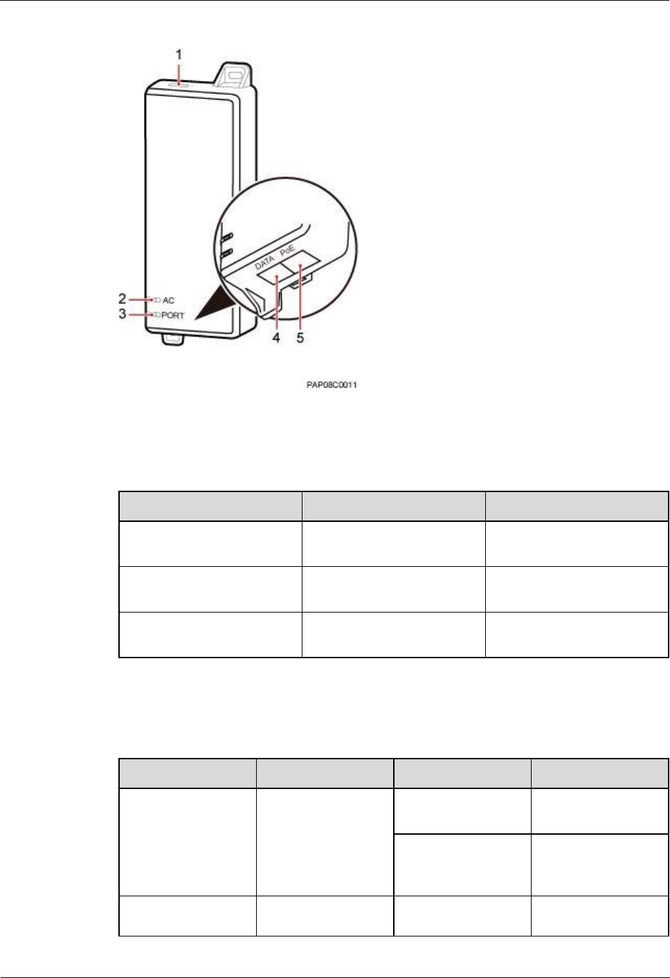
Figure 1-6 PSE ports and indicators
Table 1-4 describes PSE ports.
Table 1-4 PSE ports
No.
Label
Meaning
1
-
Power supply port used for
PSE power supply
4
DATA
Data input port connecting
to a transmission device
5
PoE
PoE output port connecting
to the eAN3710A
Table 1-5 describes PSE indicators.
Table 1-5 PSE indicators
No.
Label
Status
Description
2
AC
Steady green
The power supply is
normal.
Steady off
There is no power
input or the PSE is
faulty.
3
PORT
Steady green
The connection to
the eAN3710A is
eAN3710A
Hardware Installation Guide
1 eAN3710A Hardware Description
Issue 01 (2016-12-26)
Huawei Proprietary and Confidential
Copyright © Huawei Technologies Co., Ltd.
7
No.
Label
Status
Description
normal.
Steady off
The connection to
the eAN3710A is
abnormal or the PSE
is faulty.
Specifications
Table 1-6 lists PSE specifications.
Table 1-6 PSE specifications
Item
Specifications
Input voltage
90 V AC to 264 V AC
Input voltage frequency
47 Hz to 63 Hz
Output voltage
56 V DC
1.2.2 Dock
The Dock supplies power and transfer transmission to a eAN3710A through an Ethernet cable
in PoE mode.
Exterior
The Dock uses the modular structure. Figure 1-7 shows the exterior and dimensions of a
Dock.

eAN3710A
Hardware Installation Guide
1 eAN3710A Hardware Description
Issue 01 (2016-12-26)
Huawei Proprietary and Confidential
Copyright © Huawei Technologies Co., Ltd.
8
Figure 1-7 Exterior and dimensions of a Dock
Ports
The ports are inside the Dock. Figure 1-8 shows the positions of ports on the Dock.
Figure 1-8 Ports on the Dock
eAN3710A
Hardware Installation Guide
1 eAN3710A Hardware Description
Issue 01 (2016-12-26)
Huawei Proprietary and Confidential
Copyright © Huawei Technologies Co., Ltd.
9
Table 1-7 describes ports on the Dock.
Table 1-7 Meanings of ports on the Dock
Label
Description
OPT
FE/GE optical port, used for connecting an
external transmission devices.
L/N/PE
AC power port, used for connecting an
external power supply device.
EXT-ALM
Environment monitoring port that provides
four dry contacts, used for connecting
external devices and monitoring alarms.
WAN
P&E transmission and power supply port,
used for connecting an external transmission
device.
LAN0
P&E transmission and power supply port,
used for connecting a BTS3205E. A Dock
supplies power to only one eAN3710A.
LAN1
P&E transmission and power supply port.
Used to connect to commissioning devices,
backhaul devices, or cascaded devices.
Indicators
The Dock has three external indicators: RUN, ALM, and ACT. The internal RJ45 connector
has two indicators showing the connection status and data transmission status respectively.
The internal OPT connector has one indicator showing the connection status and data
transmission status. Figure 1-9 shows positions of external indicators on the Dock.
eAN3710A
Hardware Installation Guide
1 eAN3710A Hardware Description
Issue 01 (2016-12-26)
Huawei Proprietary and Confidential
Copyright © Huawei Technologies Co., Ltd.
10
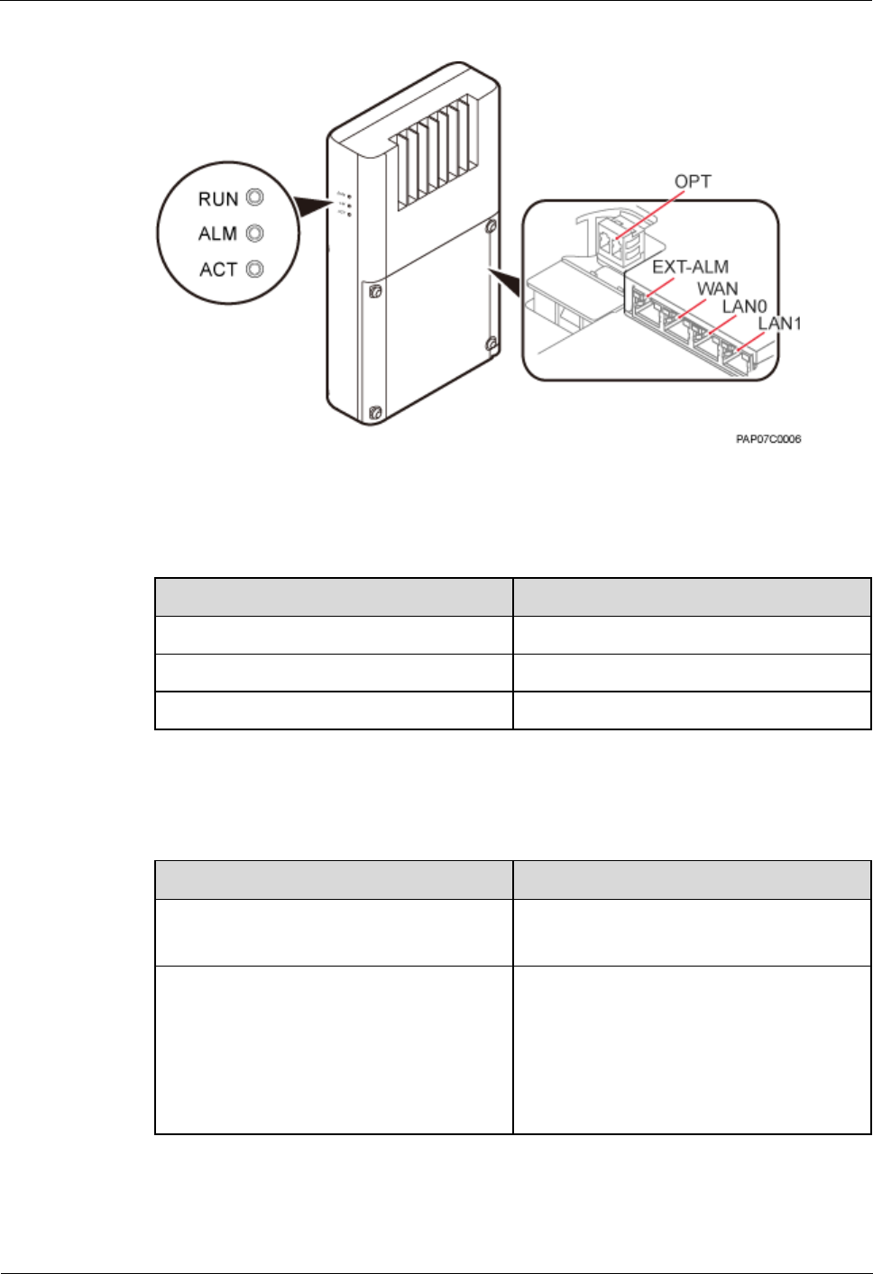
Figure 1-9 Positions of external indicators on the Dock
Table 1-8 describe indicators on the Dock external indicators.
Table 1-8 Dock external indicators
Indicator
Meaning
RUN
Operating status
ALM
Alarm status
ACT
Service status
Table 1-9 describe indicators on the Dock internal indicators.
Table 1-9 Internal indicators on the Dock
Indicator
Meaning
WAN/LAN0/LAN1
Green indicator: connection status
Orange indicator: Data transmission
OPT
Optical status
Steady green: normal connection, no data
transmission.
Fast blinking green (0.125s interval): in the
process of data transmission.
Off: faulty connection.
eAN3710A
Hardware Installation Guide
1 eAN3710A Hardware Description
Issue 01 (2016-12-26)
Huawei Proprietary and Confidential
Copyright © Huawei Technologies Co., Ltd.
11
1.3 Mounting Kits
This section describes the mounting brackets for installing a eAN3710A.
1.3.1 eAN3710A Mounting Kits
This section describes mounting kits and attachment plates for installing eAN3710A.
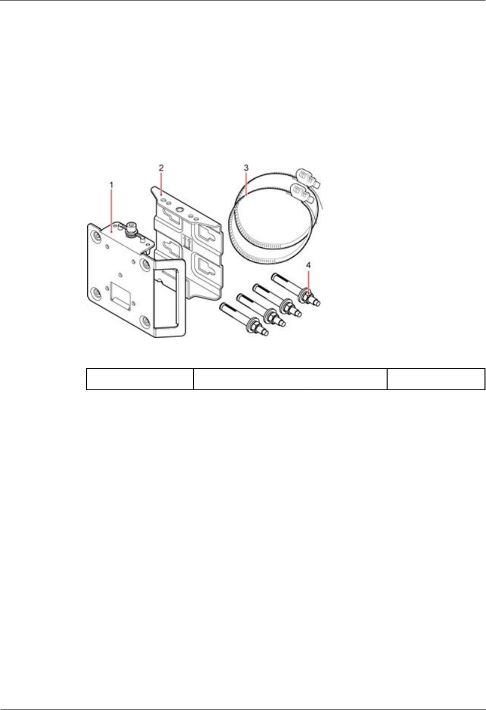
Figure 1-10 shows a mounting bracket and a attachment plate.
Figure 1-10 Mounting bracket and common attachment plate for eAN3710A
(1) Attachment plate
(2) Mounting bracket
(3) Hose clamp
(4) Expansion bolt
1.3.2 Dock Mounting Kits
This section describes the mounting brackets for installing a Dock.
Figure 1-11 shows a separate Dock mounting bracket.
eAN3710A
Hardware Installation Guide
1 eAN3710A Hardware Description
Issue 01 (2016-12-26)
Huawei Proprietary and Confidential
Copyright © Huawei Technologies Co., Ltd.
12
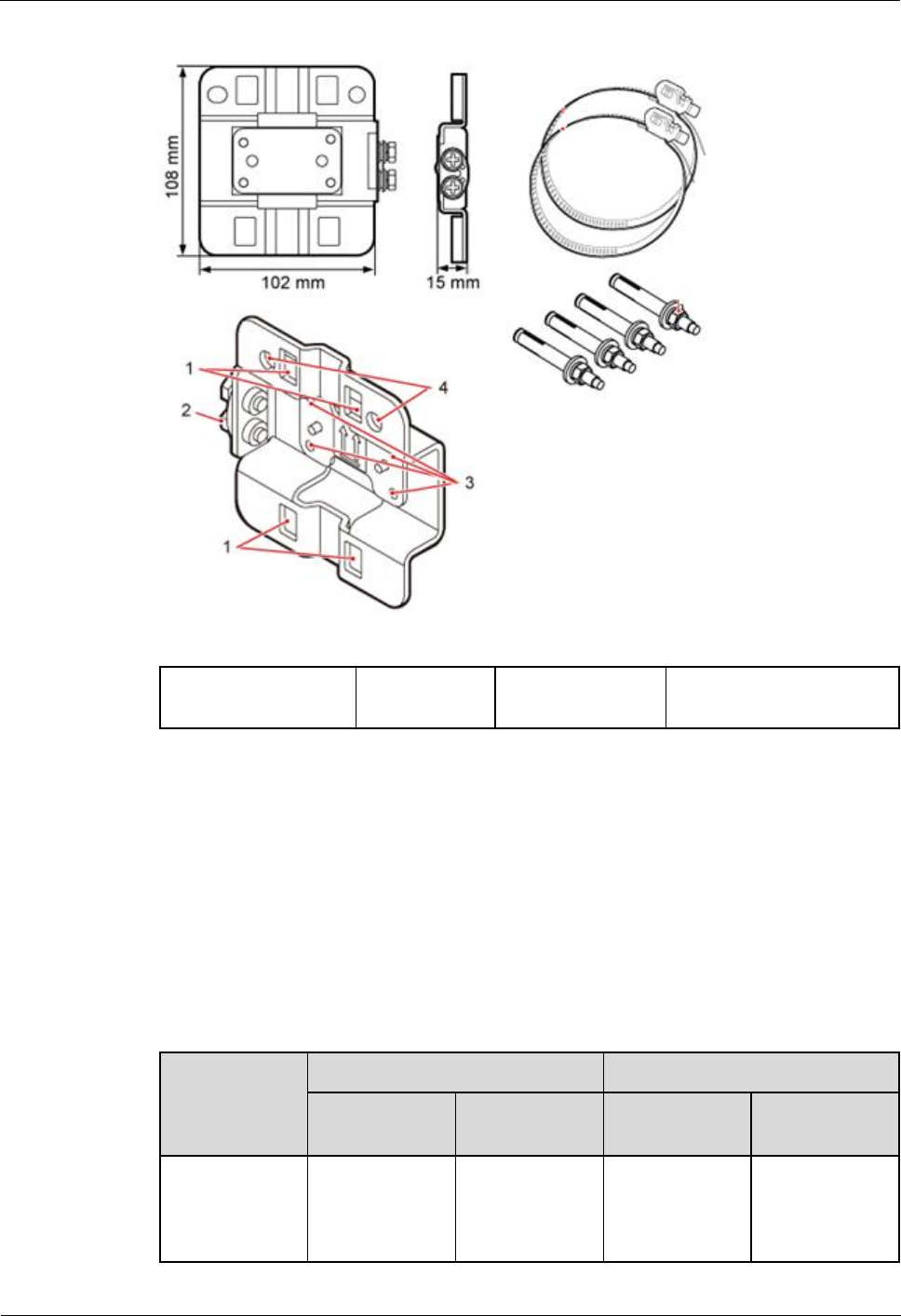
Figure 1-11 Appearance of a separate Dock mounting bracket
(1) Hole for routing a
hose clamp
(2) Ground
terminal
(3) Hole for a
captive screw
(4) Hole for inserting an
expansion bolt
1.4 Cables
This section describes eAN3710A cables.
1.4.1 Cable List
This section describes eAN3710A cable connections.
Table 1-10 lists eAN3710A cables.
Table 1-10 List of eAN3710A cables
Cable
One End
The Other End
Connector
Connected
to ...
Connector
Connected
to ...
1.4.2 Ethernet
Cable
RJ45 connector
eAN3710A/Po
E port
RJ45 connector
If connected to
PSE/DATA
port
If connected to
eAN3710A
Hardware Installation Guide
1 eAN3710A Hardware Description
Issue 01 (2016-12-26)
Huawei Proprietary and Confidential
Copyright © Huawei Technologies Co., Ltd.
13
Cable
One End
The Other End
Connector
Connected
to ...
Connector
Connected
to ...
Dock/LAN0
port
1.4.3 PGND
cable
OT terminal
(M6)
Ground
terminal on the
eAN3710A
OT terminal
(M8)
Ground
terminal on the
ground bar
OT terminal
(M6)
Ground
terminal on the
Dock
OT terminal
(M8)
Ground
terminal on the
ground bar
1.4.4 RF
Jumper
Type N male
connector
External
antenna TX/RX
RF port on
eAN3710A
Based on the
port model of
the antenna
system.
Antenna system
1.4.5 RGPS
Signal Cable
RJ45 connector
eAN3710A/RG
PS port
Round 12-pin
connector
RGPS device
1.4.2 Ethernet Cable
This section describes the appearance, pin assignment, and installation position for an
Ethernet cable connecting an auxiliary devices and a eAN3710A.
The Ethernet cable must be of Category 5e (enhanced) or higher. In addition, its cross-sectional area
must be 24 AWG or larger and frame spread rating must be CM or higher.
With the internal PoE module providing power, the maximum length of an Ethernet cable is 100 m.
Both the cable and the RJ45 connectors are delivered, and they must be assembled onsite.
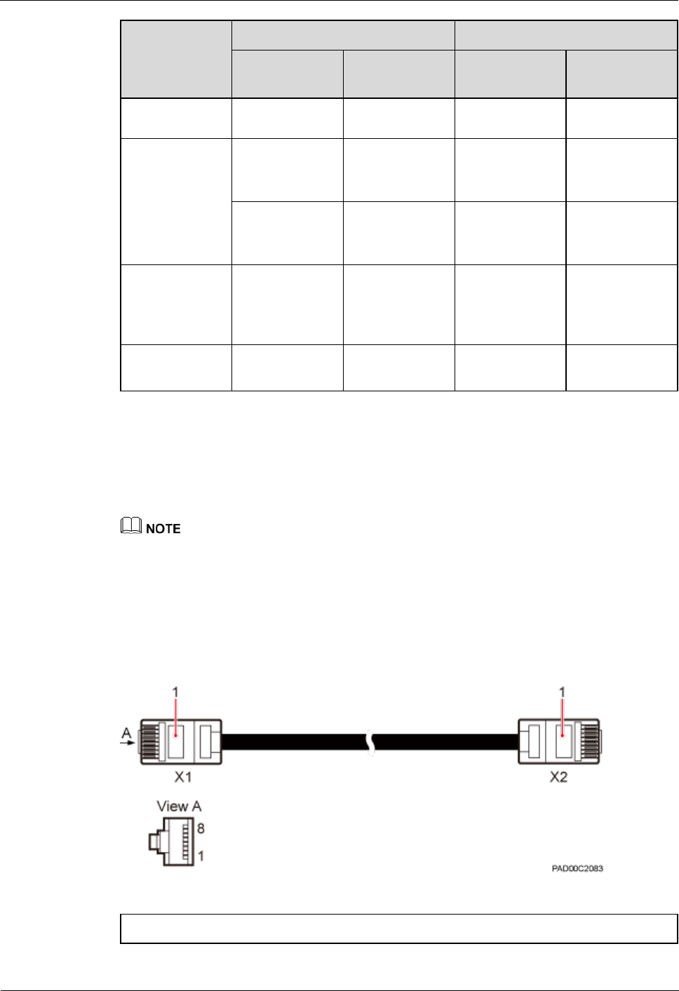
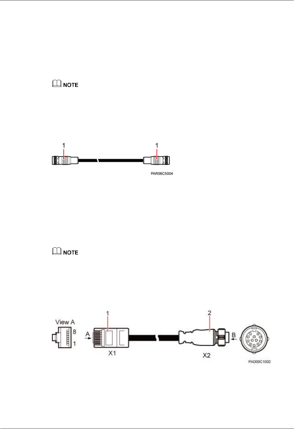
Both ends of the Ethernet cable are RJ45 connector, as shown in Figure 1-12.
Figure 1-12 Ethernet cable exterior
(1) RJ45 connector
eAN3710A
Hardware Installation Guide
1 eAN3710A Hardware Description
Issue 01 (2016-12-26)
Huawei Proprietary and Confidential
Copyright © Huawei Technologies Co., Ltd.
14
Table 1-11 shows the pin assignment for wires of the Ethernet cable.
Table 1-11 Pin assignment for wires of the Ethernet cable
Pin of the RJ45
Connector
Color
Core Wire
Pin of the RJ45 Connector
X1.2
Orange
Twisted pair
cable
X2.2
X1.1
White/Orange
X2.1
X1.6
Green
Twisted pair
cable
X2.6
X1.3
White/green
X2.3
X1.4
Blue
Twisted pair
cable
X2.4
X1.5
White/Blue
X2.5
X1.8
Brown
Twisted pair
cable
X2.8
X1.7
White/brown
X2.7
1.4.3 PGND cable
An eAN3710A PGND cable connects an eAN3710A and a ground bar, Dock and a ground bar
ensuring the proper grounding of the eAN3710A and Dock. The maximum length of an
eAN3710A PGND cable is 8 m (26.25 ft).
Exterior
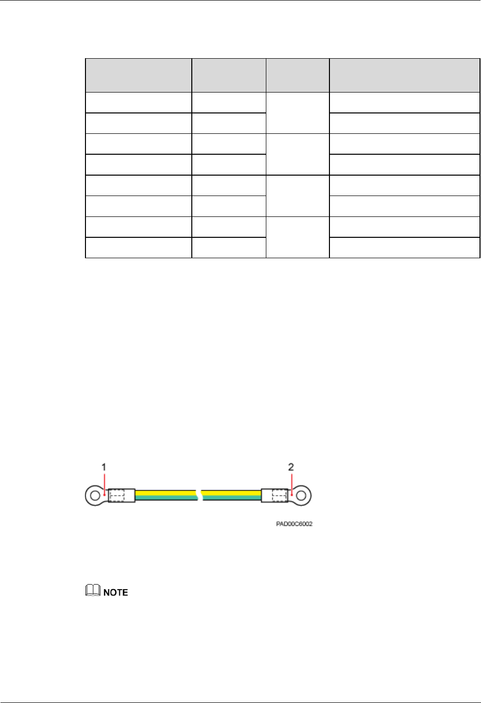
The yellow and green or green PGND cable is a single cable. The cross-sectional area of the
PGND cable is 6 mm2 (0.009 in.2). Both ends of the cable are OT terminals, as shown in
Figure 1-13.
Figure 1-13 Exterior of a PGND cable
(1) OT terminal (M6)
(2) OT terminal (M8)
If the PGND cable is provided by the customer, a copper-core cable with a minimum cross-sectional
area of 6 mm2 (0.009 in.2) or 10 AWG is recommended.
The OT terminals at both ends of the PGND cable are assembled at the site.
The M6 OT terminal has the default size. You can replace it with another OT terminal of the
expected size based on the site requirement.
eAN3710A
Hardware Installation Guide
1 eAN3710A Hardware Description
Issue 01 (2016-12-26)
Huawei Proprietary and Confidential
Copyright © Huawei Technologies Co., Ltd.
15
Installation Position
The M6 OT terminal of the PGND cable is connected to the ground screw on the eAN3710A
and Dock, and the M8 OT terminal of the PGND cable is connected to the ground bar at the
site.
1.4.4 RF Jumper
The eAN3710A RF jumper transmits and receives RF signals.
If the customer prepares the RF jumper, the length of the RF jumper should be as short as possible and
not exceed 2 m (6.56 ft.).
Both end of the outdoor RF jumper is the type N male connector. Figure 1-14 shows the RF
jumper.
Figure 1-14 RF jumper
(1) Type N male connector
1.4.5 RGPS Signal Cable
The RGPS signal cable between the eAN3710A and RGPS device is used for clock
synchronization. This cable is optional for the eAN3710A.
If the customer uses their own radio frequency (RF) jumpers, it is recommended that the length of RF
jumpers be 2 m.
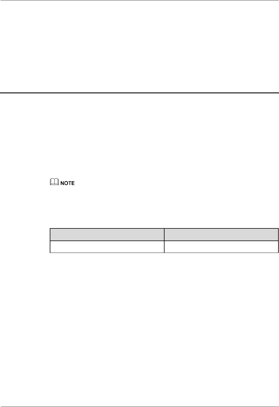
An RGPS signal cable has an RJ45 connector at one end and a round 12-pin connector at the
other end, as shown in Figure 1-15.
Figure 1-15 Appearance of an RGPS signal cable
(1) RJ45 connector
(2) Round 12-pin connector
eAN3710A
Hardware Installation Guide
2 eAN3710A Hardware Installation Guide
Issue 01 (2016-12-26)
Huawei Proprietary and Confidential
Copyright © Huawei Technologies Co., Ltd.
16
2 eAN3710A Hardware Installation Guide
About This Chapter
Overview
This document describes the process of installing eAN3710A.
Product Version
Unless otherwise stated, "eNodeB", "Pico", "eAN", and "AirNode" in this document refer to the 3710
series AirNode.
The 3710 series AirNode is a base station that provides communications services in Huawei
eLTE-IoT solution. The following table lists the product name and product version related to
the 3710 series AirNode.
Product Name
Product Version
eAN3710A
V100R001C00
Intended Audience
This document is intended for installation engineers.
Organization
2.1 Installation Preparations
Before starting the installation, you must obtain the required reference documents, tools, and
instruments, and familiarize yourself with the skills required.
2.2 Information About the Installation
This section describes the information that you must be familiar with before installing a
eAN3710A, including the eAN3710A hardward infomation, installation scenarios, installation
space and environment requirements.
2.3 Unpacking the Equipment

eAN3710A
Hardware Installation Guide
2 eAN3710A Hardware Installation Guide
Issue 01 (2016-12-26)
Huawei Proprietary and Confidential
Copyright © Huawei Technologies Co., Ltd.
17
This section describes how to unpack and check the delivered equipment to ensure that all the
materials are included and intact.
2.4 Installation Process
This section describes the eAN3710A installation process.
2.5 Obtaining the ESN
Before installing the eAN3710A, record its electronic serial number (ESN) for future use
during commissioning.
2.6 (Optional) Installing a Micro SD Card
This section describes how to install a micro SD card in the eAN3710A.
2.7 Installing the eAN3710A
This section describes the eAN3710A installation process.
2.8 Installing the Auxiliary Devices
This section describes the procedure and precautions for installing the auxiliary devices.
2.9 Installing eAN3710A Cables
This section describes the procedures for installing eAN3710A cables and auxiliary devices
cables.
2.10 Checking the eAN3710A Hardware Installation
eAN3710A hardware installation checking includes hardware and cable installation checking.
2.11 Power-On Check on the eAN3710A
This section describes the procedure for performing a power-on check on the eAN3710A.
2.12 Appendix
This section describes reference information during installation.
2.1 Installation Preparations
Before starting the installation, you must obtain the required reference documents, tools, and
instruments, and familiarize yourself with the skills required.
2.1.1 Reference Documents
Before the installation, you must be familiar with reference documents.
The following reference documents are required during eAN3710A installation:
Health and Safety
Equipment Safety
1 eAN3710A Hardware Description
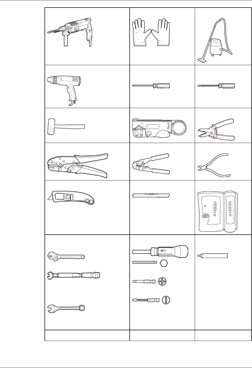
2.1.2 Tools and Instruments
You must prepare the following tools and instruments before the installation.
eAN3710A
Hardware Installation Guide
2 eAN3710A Hardware Installation Guide
Issue 01 (2016-12-26)
Huawei Proprietary and Confidential
Copyright © Huawei Technologies Co., Ltd.
18
Hammer drill (a φ12 bit)
ESD gloves
Vacuum cleaner
Heat gun
Phillips screwdriver (M3
to M6)
Flat-head screwdriver
(M3 to M6)
Rubber mallet
COAX crimping tool
Wire stripper
Power cable crimping tool
RJ45 crimping tool
Diagonal plier
Utility knife
Level
Network cable tester
Adjustable wrench (size ≥ 32 mm
[1.26 in.])
Torque wrench
Size: 16 mm (0.63 in.) and 22 mm
(0.87 in.)
Combination wrench
Size: 16 mm (0.63 in.) and 22 mm
(0.87 in.)
Torque screwdriver
3mm or 5mm
(M3 to M6)
(M3 to M6)
Marker (diameter ≤ 10
mm [0.39 in.])
Torque socket (M6 or M10)
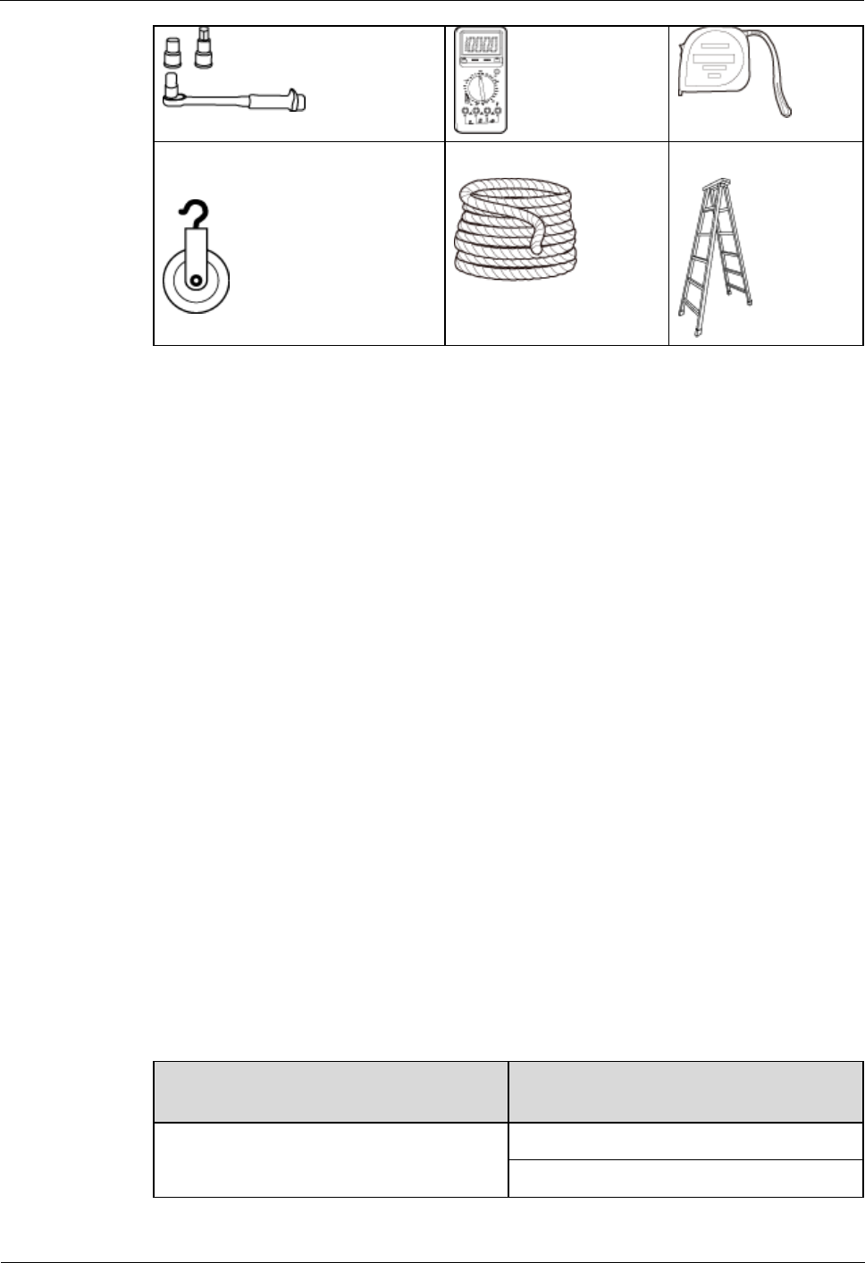
Multimeter
Measuring tape
eAN3710A
Hardware Installation Guide
2 eAN3710A Hardware Installation Guide
Issue 01 (2016-12-26)
Huawei Proprietary and Confidential
Copyright © Huawei Technologies Co., Ltd.
19
Fixed pulley(weight-bearing
capacity > 500 kg or 1102.5 lb)
Lifting sling
Ladder
2.1.3 Requirements for Installation Personnel
This section describes requirements for installation engineers. They must be qualified and
trained, and familiar with correct operation methods and safety precautions before performing
any operations.
Before the installation, pay attention to the following items:
Technical engineers must take Huawei training and be familiar with proper installation
and operation methods.
The number of installation personnel depends on the engineering schedule and
installation environment. Generally, two to three persons are required. Generally, only
three to five onsite personnel are necessary.
2.2 Information About the Installation
This section describes the information that you must be familiar with before installing a
eAN3710A, including the eAN3710A hardward infomation, installation scenarios, installation
space and environment requirements.
2.2.1 Hardware Device Information
This section describes the hardware information you should know before installing the
eAN3710A.
eAN3710A hardware includes eAN3710A main equipment, auxiliary devices, mounting kits,
and cables. For details, see sections in eAN3710A Hardware Description, which are listed in
Table 2-1.
Table 2-1 Hardware information
Category
Sections in eAN3710A Hardware
Description
eAN3710A main equipment
1.1.1 eAN3710A Exterior
1.1.2 eAN3710A Ports
eAN3710A
Hardware Installation Guide
2 eAN3710A Hardware Installation Guide
Issue 01 (2016-12-26)
Huawei Proprietary and Confidential
Copyright © Huawei Technologies Co., Ltd.
20
Category
Sections in eAN3710A Hardware
Description
1.1.3 eAN3710A Indicators
Auxiliary device
1.2.1 PSE
1.2.2 Dock
Mounting kits
1.3.1 eAN3710A Mounting Kits
1.3.2 Dock Mounting Kits
Cables
1.4.1 Cable List
2.2.2 Installation Options and Restrictions
The eAN3710A can be installed on a wall or pole. Installation scenarios must meet
heat-dissipation and waterproofing requirements of the eAN3710A.
Installation on a Pole
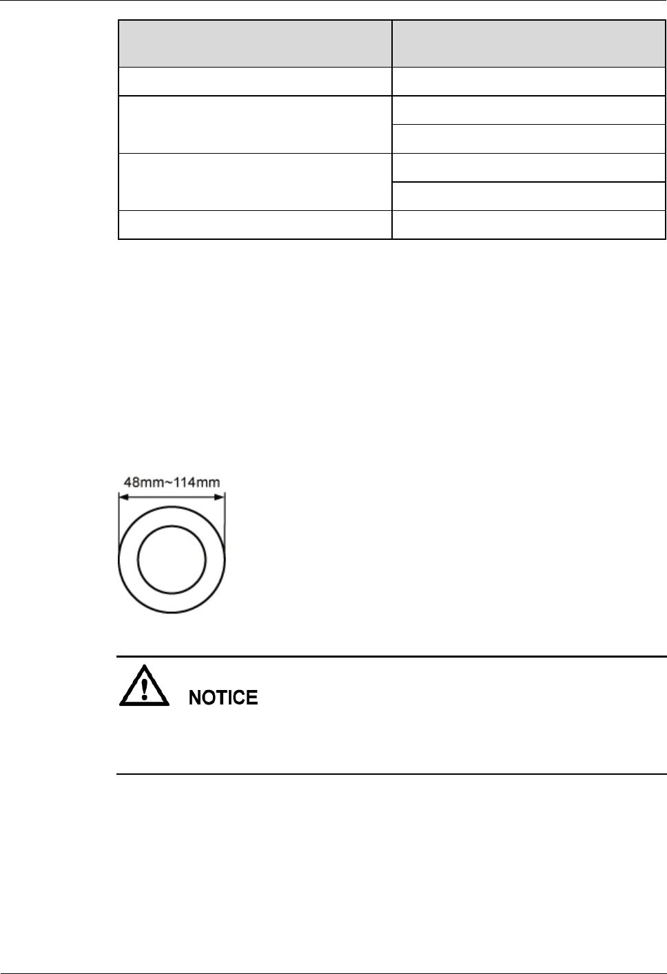
Figure 2-1 shows the diameter of a pole for installing an eAN3710A.
Figure 2-1 Diameter of a pole for installing a eAN3710A
The diameter of a pole for installing a eAN3710A ranges from 48 mm (1.89 in.) to 114
mm (4.49 in.). The recommended diameter is 60 mm (2.36 in.).
The recommended thickness of the pole wall is 3.5 mm (0.14 in.) or above.
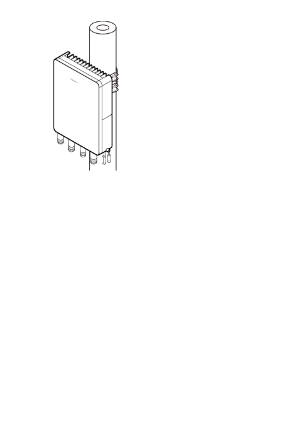
Figure 2-2 shows the eAN3710A installed on a pole.
eAN3710A
Hardware Installation Guide
2 eAN3710A Hardware Installation Guide
Issue 01 (2016-12-26)
Huawei Proprietary and Confidential
Copyright © Huawei Technologies Co., Ltd.
21
Figure 2-2 A eAN3710A installed on a pole
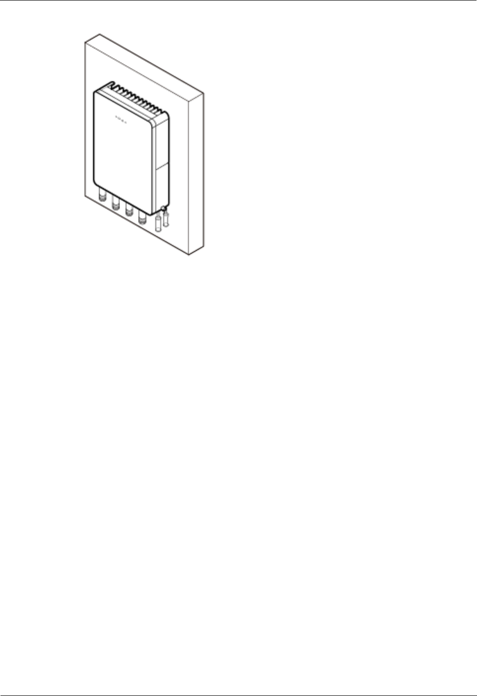
Installation on a Wall
The wall for installing eAN3710A must meet the following requirements:
The wall can bear a load at least four times the weight of a eAN3710A.
The screws must be tightened with a torque of 30 N·m. This ensures the screws work
properly and the wall remains intact without cracks in it.
Figure 2-3 shows the eAN3710A installed on a pole.
eAN3710A
Hardware Installation Guide
2 eAN3710A Hardware Installation Guide
Issue 01 (2016-12-26)
Huawei Proprietary and Confidential
Copyright © Huawei Technologies Co., Ltd.
22
Figure 2-3 A eAN3710A installed on a wall
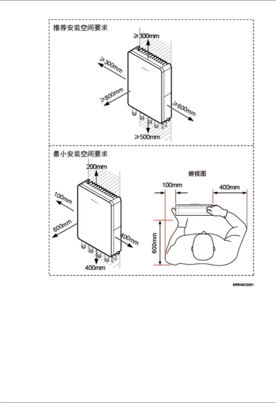
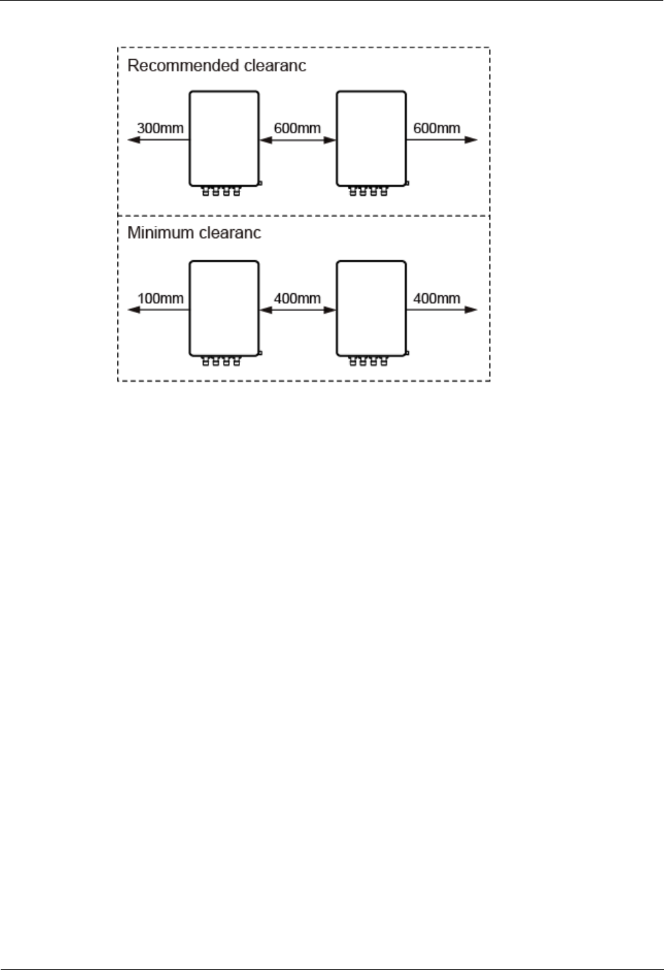
2.2.3 Installation Clearance and Space Requirements
This section describes the recommended and minimum clearances for a eAN3710A.
Clearance for a eAN3710A
When the eAN3710A is installed on a wall or pole, the minimum clearance is required for
easy cabling and operation and maintenance (O&M). Based on the engineering practice, the
recommendation for the installation clearance is provided.
The recommended clearances are for customers, ensuring normal running and providing
appropriate space for O&M. If installation space is sufficient, leave the recommended
clearances after installing equipment.
The minimum clearance ensures normal operation and heat dissipation, but O&M
activities such as checking indicator status and opening the cover plate of a cabling
cavity cannot be properly conducted. If installation space is restricted, leave the
minimum clearance after installing equipment.
Figure 2-4 show the clearances for installing a eAN3710A.
eAN3710A
Hardware Installation Guide
2 eAN3710A Hardware Installation Guide
Issue 01 (2016-12-26)
Huawei Proprietary and Confidential
Copyright © Huawei Technologies Co., Ltd.
23
Figure 2-4 Clearances for installing a eAN3710A
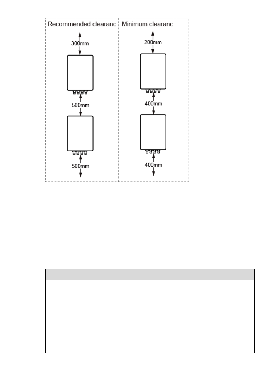
Installation Spacing Between eAN3710A
Figure 2-5 lists the horizonta spacing between eAN3710A.
eAN3710A
Hardware Installation Guide
2 eAN3710A Hardware Installation Guide
Issue 01 (2016-12-26)
Huawei Proprietary and Confidential
Copyright © Huawei Technologies Co., Ltd.
25
Figure 2-6 Clearances for installing a eAN3710A
2.2.4 Installation Environment Requirements
The installation environment of a eAN3710A involves the running environment specifications
for the eAN3710A.
Running Environment Specifications
Table 2-2 shows the environment specifications for the eAN3710A.
Table 2-2 Environment specifications of eAN3710A
Item
Specifications
Operating temperature
-40ºC to +45ºC (with solar radiation)
-40ºC to +50ºC (without solar radiation)
NOTE
At -40ºC to -20ºC, the AirNode can start up, but
its performance cannot meet requirements. At
-20ºC to +50ºC, the performance of the AirNode
meets requirements.
Storage temperature
-40ºC to +70ºC
Relative humidity
5% RH to 95% RH
eAN3710A
Hardware Installation Guide
2 eAN3710A Hardware Installation Guide
Issue 01 (2016-12-26)
Huawei Proprietary and Confidential
Copyright © Huawei Technologies Co., Ltd.
26
Item
Specifications
Absolute humidity
1 g/m3 to 30 g/m3
Atmospheric pressure
70 kPa to 106 kPa
Protection class
IP65
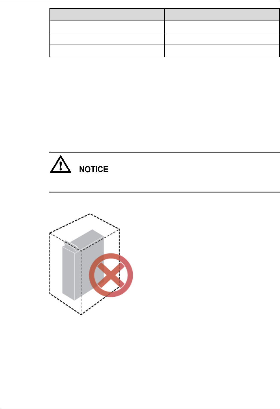
Requirements for the Installation Scenarios
To ensure proper heat dissipation of the eAN3710A, the following requirements must be met:
The eAN3710A cannot be installed in an enclosed cabinet without a cooling system.
The eAN3710A cannot be installed in an enclosed camouflage box.
The eAN3710A cannot be installed in an enclosed equipment room without a cooling
system.
If the eAN3710A is inappropriately installed, heat dissipation of the eAN3710A deteriorates
and the eAN3710A may not work properly, as shown in Figure 2-7.
Figure 2-7 Inappropriately installed eAN3710A
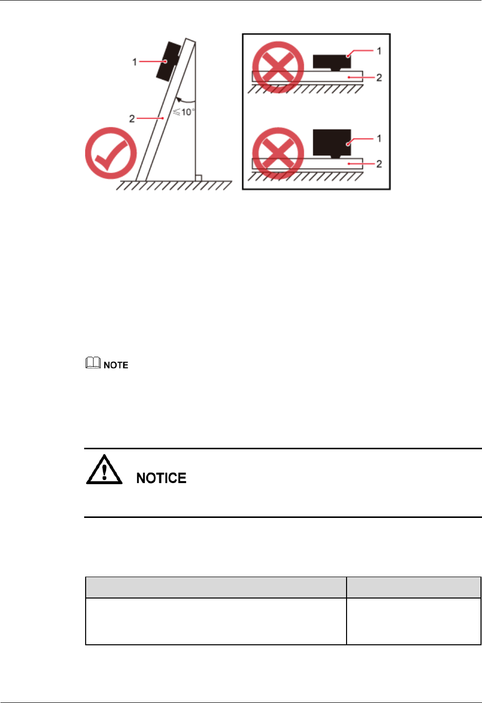
Requirements for the Installation methods
To ensure the heat dissipation of the eAN3710A and waterproofing of the ports at the bottom
of the eAN3710A, the vertical deviation angle of a eAN3710A must be less than or equal to
10°, as shown in Figure 2-8.
eAN3710A
Hardware Installation Guide
2 eAN3710A Hardware Installation Guide
Issue 01 (2016-12-26)
Huawei Proprietary and Confidential
Copyright © Huawei Technologies Co., Ltd.
27
Figure 2-8 Requirements for the vertical deviation angle of a eAN3710A
(1) eAN3710A
(2) Installation support (pole or wall)
2.3 Unpacking the Equipment
This section describes how to unpack and check the delivered equipment to ensure that all the
materials are included and intact.
Context
When transporting, moving, or installing the equipment, components, or parts, you must:
Prevent them from colliding with doors, walls, shelves, or other objects.
Wear clean gloves, and avoid touching the equipment, components, or parts with bare hands,
sweat-soaked gloves, or dirty gloves.
Power on an eAN3710A within 24 hours after unpacking it. If you power off an eAN3710A
for maintenance, restore power to the eAN3710A within 24 hours.
Procedure
Step 1 Count the total number of the shipments.
If...
Then...
The total number of the components is consistent
with that recorded in the packing lists on all
packing boxes
Go to Step 2.
eAN3710A
Hardware Installation Guide
2 eAN3710A Hardware Installation Guide
Issue 01 (2016-12-26)
Huawei Proprietary and Confidential
Copyright © Huawei Technologies Co., Ltd.
28
If...
Then...
The total number of the components is inconsistent
with that recorded in the packing lists on all
packing boxes
Report the problems and
causes to the local Huawei
office.
Step 2 Check the exterior of each packing box.
If...
Then...
The exterior of each packing box is
intact
Go to Step 3.
It is damaged or soaked
Report the problems and causes to the local
Huawei office.
Step 3 Check the type and quantity of the equipment in the boxes according to the packing list.
If...
Then...
The type and number are consistent with the
packing list on each packing list
Sign the Packing List with the
operator.
There is any shortage, wrong delivery, or
damaged equipment
Report the problems and causes to
the local Huawei office.
To protect the equipment from damage, keep the unpacked equipment and packing materials
indoors. To help find out the cause of any damage in the future, take photos of the storeroom,
rusted or eroded equipment, packing cases, and packing materials, and then file the photos.
----End
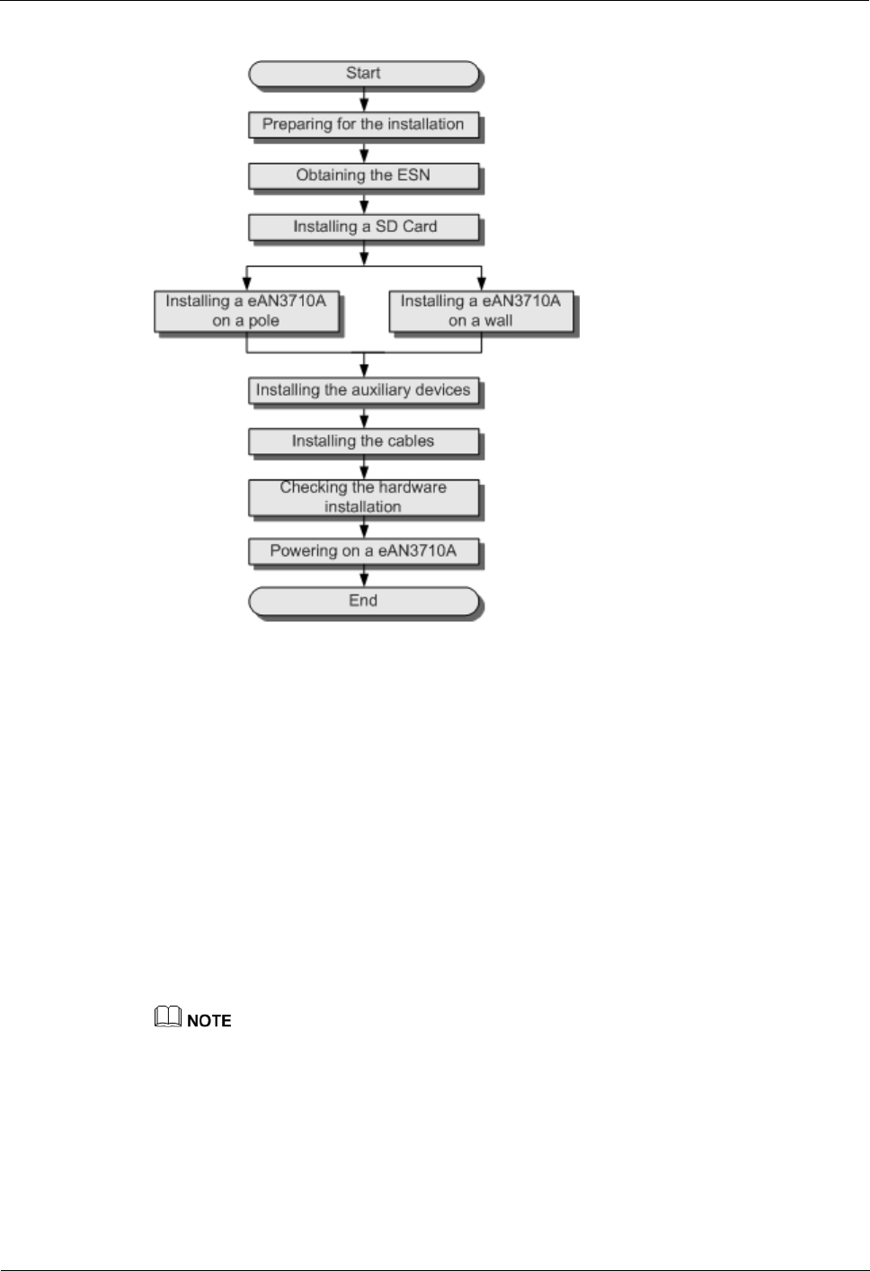
2.4 Installation Process
This section describes the eAN3710A installation process.
Figure 2-9 shows the eAN3710A installation process.
eAN3710A
Hardware Installation Guide
2 eAN3710A Hardware Installation Guide
Issue 01 (2016-12-26)
Huawei Proprietary and Confidential
Copyright © Huawei Technologies Co., Ltd.
29
Figure 2-9 eAN3710A installation process
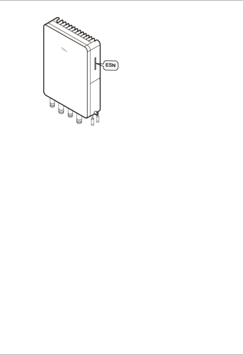
2.5 Obtaining the ESN
Before installing the eAN3710A, record its electronic serial number (ESN) for future use
during commissioning.
Context
The ESN uniquely identifies a device and is required during commissioning.
Procedure
Step 1 Remove the backup ESN label from the surface of the eAN3710A. as shown in Figure 2-10.
Before removing the backup SN label, photograph it.
eAN3710A
Hardware Installation Guide
2 eAN3710A Hardware Installation Guide
Issue 01 (2016-12-26)
Huawei Proprietary and Confidential
Copyright © Huawei Technologies Co., Ltd.
30
Figure 2-10 Removing the ESN label
Step 2 Record the ESN by using the template described in section 2.12.1 ESN Collection Template,
and report it to the eAN3710A commissioning personnel.
----End
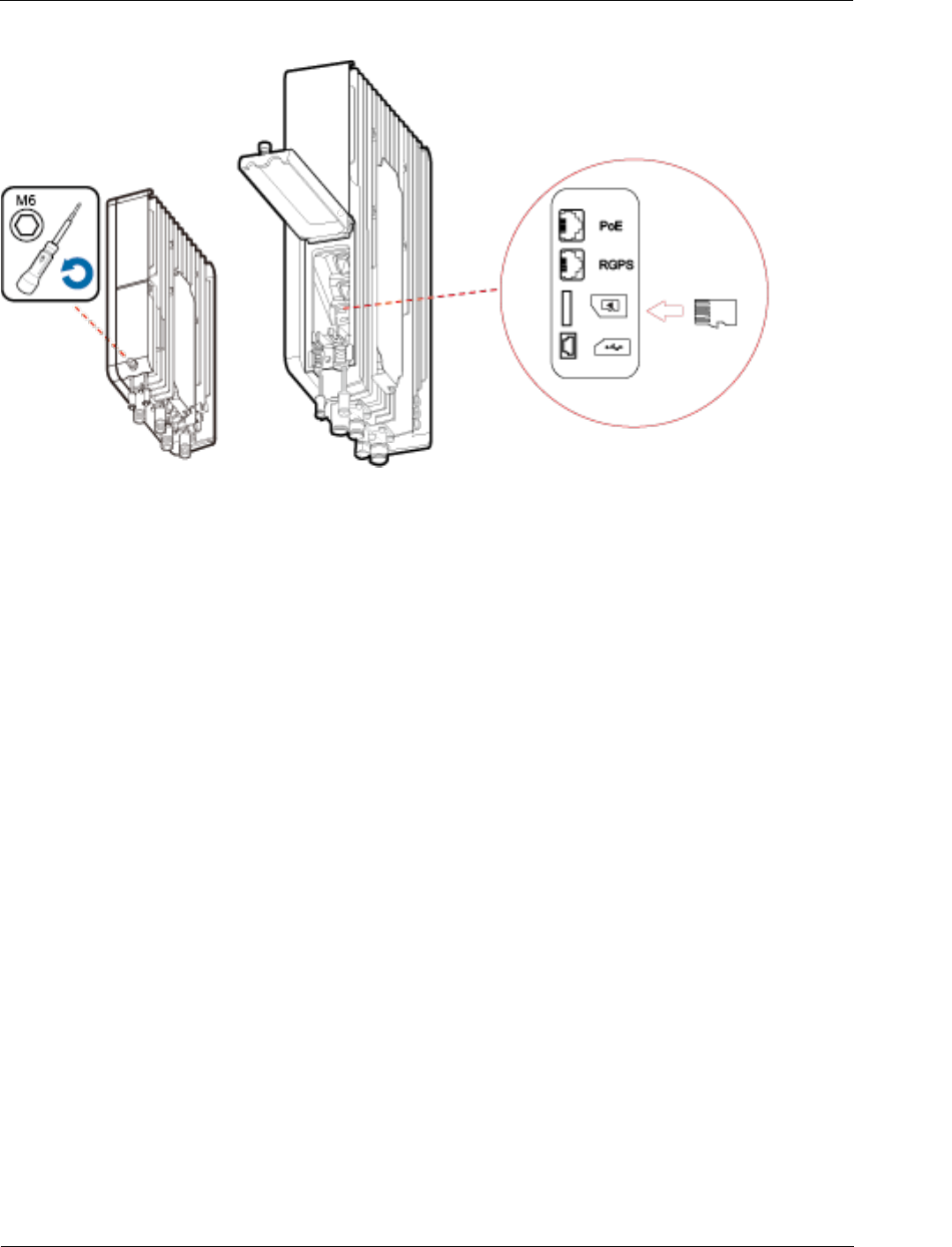
2.6 (Optional) Installing a Micro SD Card
This section describes how to install a micro SD card in the eAN3710A.
Prerequisites
Software and configuration data files need to be prepared for the micro SD card to be installed.
For detailed operations, see eAN3710A Deployment Guide.
Procedure
Step 1 Wear ESD gloves.
Step 2 Use an M5 inner hexagon screwdriver to loosen a screw on the cabling cavity panel and open
the cabling cavity on the side.
Step 3 Install a micro SD card in the micro SD card slot, as shown in Figure 2-11.
eAN3710A
Hardware Installation Guide
2 eAN3710A Hardware Installation Guide
Issue 01 (2016-12-26)
Huawei Proprietary and Confidential
Copyright © Huawei Technologies Co., Ltd.
31
Figure 2-11 Installing a micro SD card
Step 4 Cover the plate for the cabling cavity and use the screwdriver to tighten the screw.
----End
2.7 Installing the eAN3710A
This section describes the eAN3710A installation process.
2.7.1 Installing eAN3710A on a Pole
This section describes the procedure and precautions for installing an eAN3710A on a pole.
Context
Do not stand an eAN3710A upright because the RF ports cannot support the weight of
the eAN3710A.
Place a foam pad or cardboard under an eAN3710A to protect the eAN3710A housing
from damage during the installation.
Procedure
Step 1 Determine a position for installing the separate mounting kit, as shown in Figure 2-12.
eAN3710A
Hardware Installation Guide
2 eAN3710A Hardware Installation Guide
Issue 01 (2016-12-26)
Huawei Proprietary and Confidential
Copyright © Huawei Technologies Co., Ltd.
32
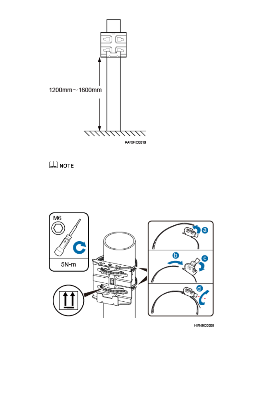
Figure 2-12 Distance between the separate mounting kit and the ground
It is recommended that the mounting kits be installed at a position 1200 mm (47.24 in.) to 1600 mm
(59.06 in.) high above the ground.
Step 2 Install the mounting kit, as shown in Figure 2-13.
Figure 2-13 Installing the eAN3710A mounting kit
1. Determine a position for installing the eAN3710A. Then, place the separate mounting kit
onto the pole, thread the hose clamp through the mounting kit, and encircle the pole with
the hose clamp, as shown by illustrations a, b, and c in Figure 2-13.
2. Use an M6 inner hexagon screwdriver to tighten the bolt on each hose clamp to 7 N·m
(61.96 lbf·in.) to secure the mounting kit, as shown by illustration d in Figure 2-13.
Step 3 Secure the eAN3710A onto the separate mounting kit, as shown in Figure 2-14.
eAN3710A
Hardware Installation Guide
2 eAN3710A Hardware Installation Guide
Issue 01 (2016-12-26)
Huawei Proprietary and Confidential
Copyright © Huawei Technologies Co., Ltd.
33
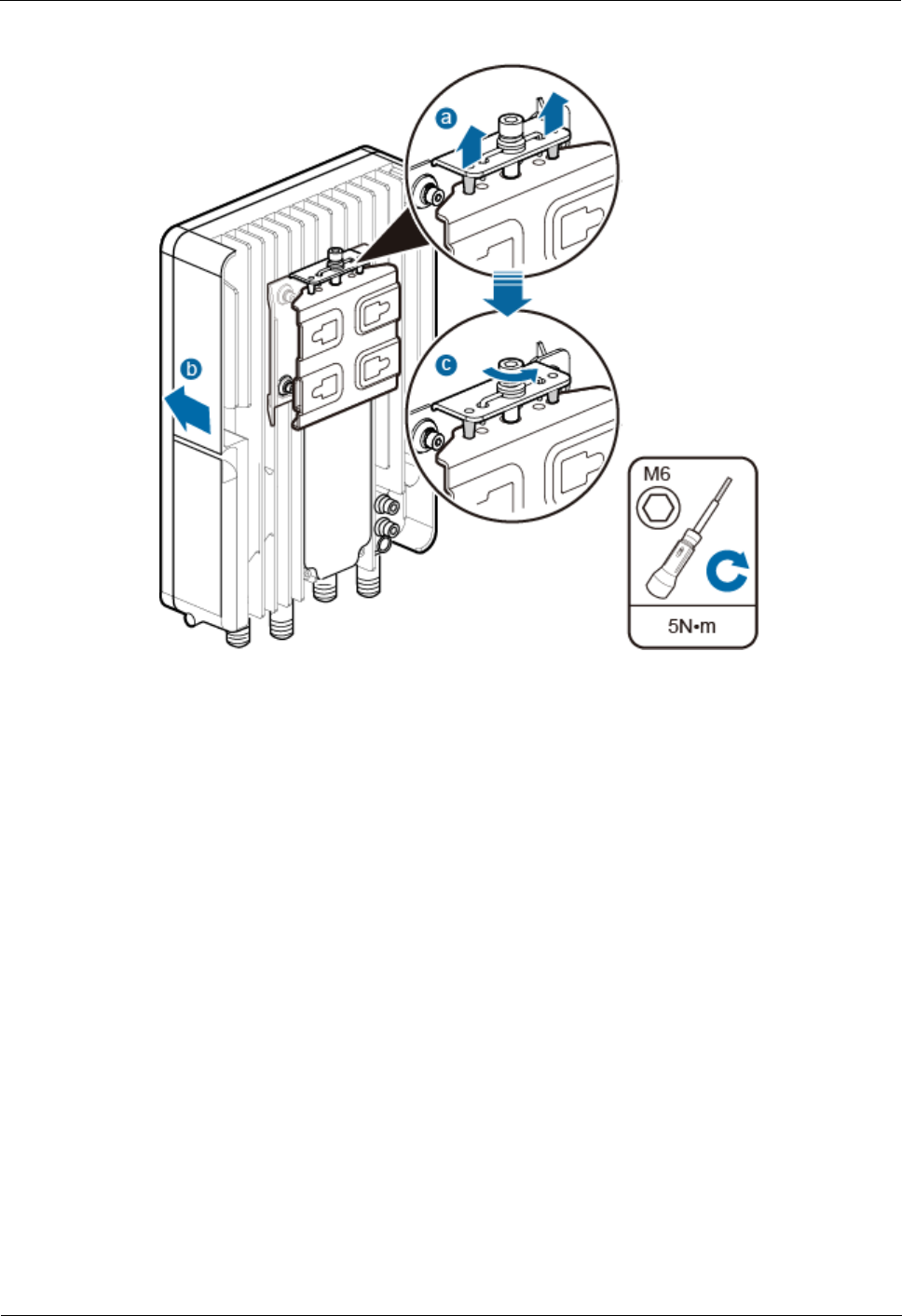
Figure 2-14 Securing the eAN3710A onto the mounting kit
1. Hang the two dowels on the top of the eAN3710A attachment plate onto the mounting
kit, and push the eAN3710A until it snaps into place, as shown by illustrations a and b in
Figure 2-14.
2. Use the M6 inner hexagon screwdriver to tighten the screw on the top of the attachment
plate to 5 N·m (44.25 lbf·in.), as shown by illustration c in Figure 2-14.
----End
2.7.2 Installing eAN3710A on a Wall
This section describes the procedure and precautions for installing an eAN3710A on a wall.
Context
The wall for installing eAN3710As must meet the following requirements:
The wall must be able to bear a weight four times heavier than the eAN3710A's weight.
Expansion bolts must be tightened to 30 N·m (265.52 lbf·in.) to ensure that the bolt
assemblies work properly and the wall remains intact.
eAN3710A
Hardware Installation Guide
2 eAN3710A Hardware Installation Guide
Issue 01 (2016-12-26)
Huawei Proprietary and Confidential
Copyright © Huawei Technologies Co., Ltd.
34
Do not stand an eAN3710A upright because the RF ports cannot support the weight of the
eAN3710A.
Place a foam pad or cardboard under an eAN3710A to protect the eAN3710A housing
from damage during the installation.
Procedure
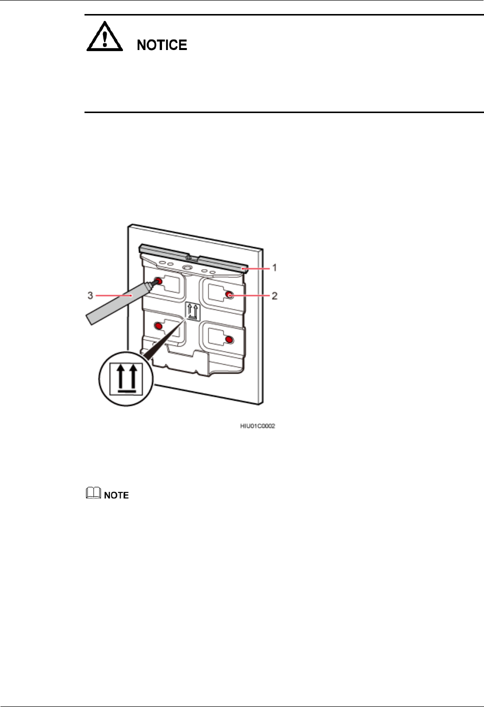
Step 1 Determine a position for installing the eAN3710A on a wall, use a level to verify that the
marking-off template is placed horizontally, and then use a marker to mark anchor points, as
shown in Figure 2-15.
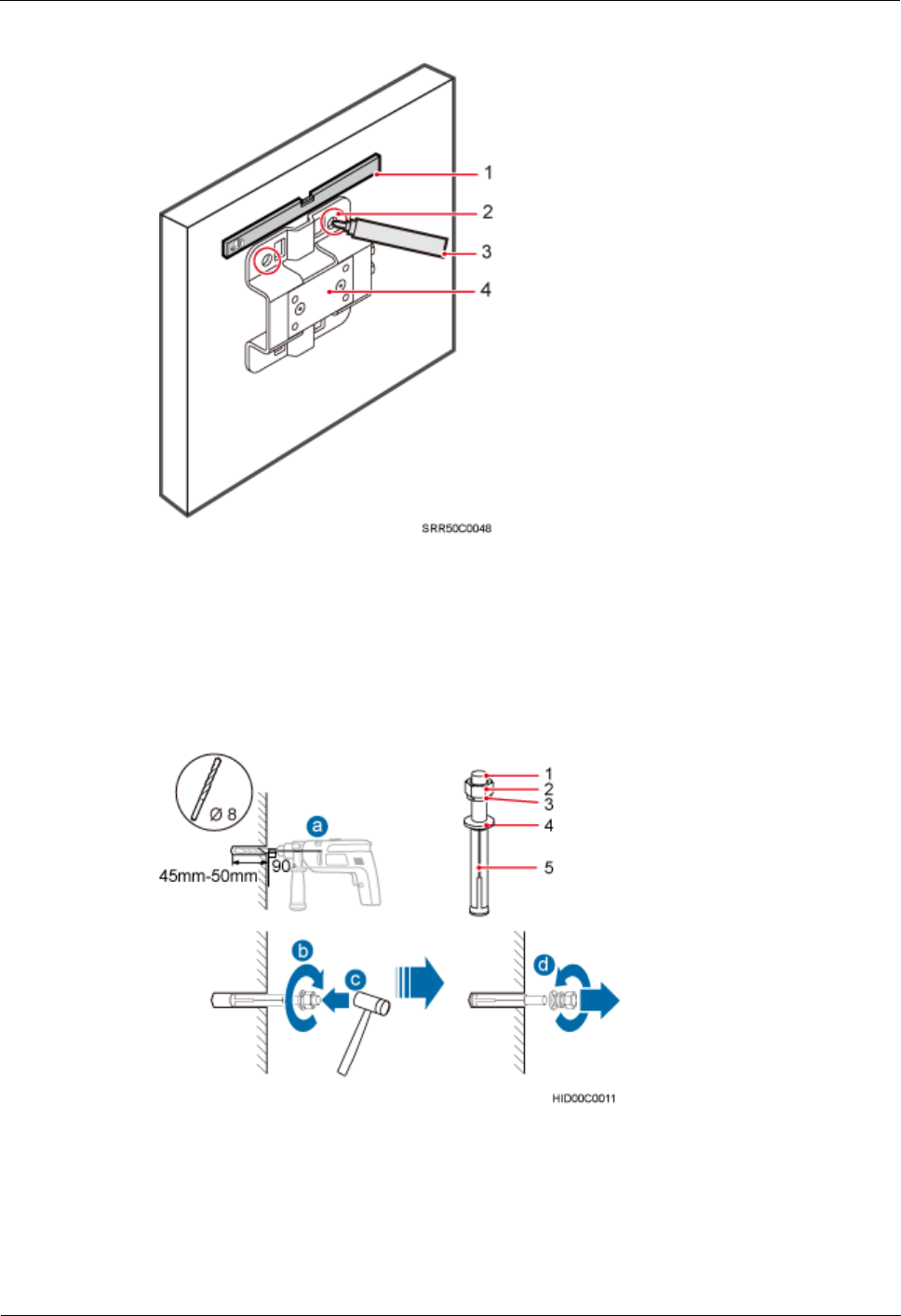
Figure 2-15 Marking anchor points
(1) Level
(2) Tapped hole
(3) Marker
It is recommended that the separate mounting kit be 1200 mm (47.24 in.) to 1600 mm (62.99 in.) above
the ground.
Step 2 Drill holes at the anchor points and install expansion bolts in the holes, as shown in Figure
2-16.
eAN3710A
Hardware Installation Guide
2 eAN3710A Hardware Installation Guide
Issue 01 (2016-12-26)
Huawei Proprietary and Confidential
Copyright © Huawei Technologies Co., Ltd.
35
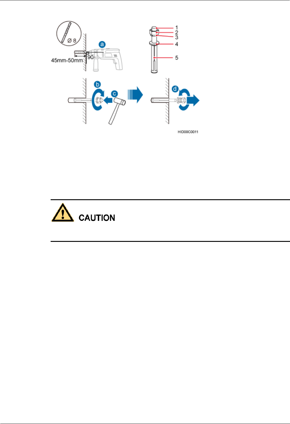
Figure 2-16 Drilling a hole and inserting an expansion bolt assembly
(1) M6x60 bolt
(2) Nut
(3) Spring washer
(4) Flat washer
(5) Expansion tube
1. Use a hammer drill with a φ8 bit to drill holes vertically at the marked anchor points.
Ensure that the depth of each hole ranges from 45 mm (1.77 in.) to 50 mm (1.97 in.).
Take proper safety measures to protect your eyes and respiratory tract against the dust before
drilling holes.
2. Use a vacuum cleaner to clear the dust out from inside and around the holes, and
measure the distances between holes. If any of the holes is beyond the acceptable range,
mark a new anchor point and drill a new hole.
3. Tighten the expansion bolts slightly, and place each expansion bolt vertically into each
hole.
4. Use a rubber mallet to pound each expansion bolt until the corresponding expansion tube
completely enters the hole. Leave 20 mm (0.79 in.) of the expansion bolt outside the
wall.
5. Remove the M6x60 bolt, nut, spring washer, and flat washer in sequence.
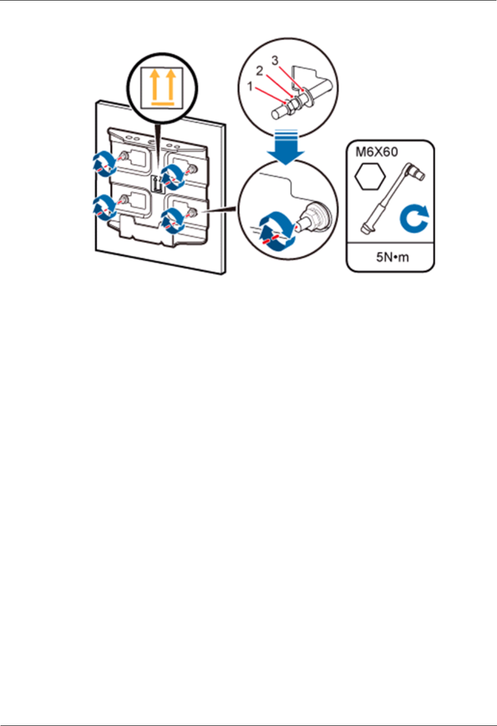
Step 3 Place the mounting kit onto the wall, insert four M6x60 bolts into the tapped holes on the
mounting kit, and tighten each bolt to 5 N·m (44.25 lbf·in.) to secure the mounting kit, as
shown in Figure 2-17.
eAN3710A
Hardware Installation Guide
2 eAN3710A Hardware Installation Guide
Issue 01 (2016-12-26)
Huawei Proprietary and Confidential
Copyright © Huawei Technologies Co., Ltd.
36
Figure 2-17 Securing the separate mounting kit
(1) Nut
(2) Spring washer
(3) Flat washer
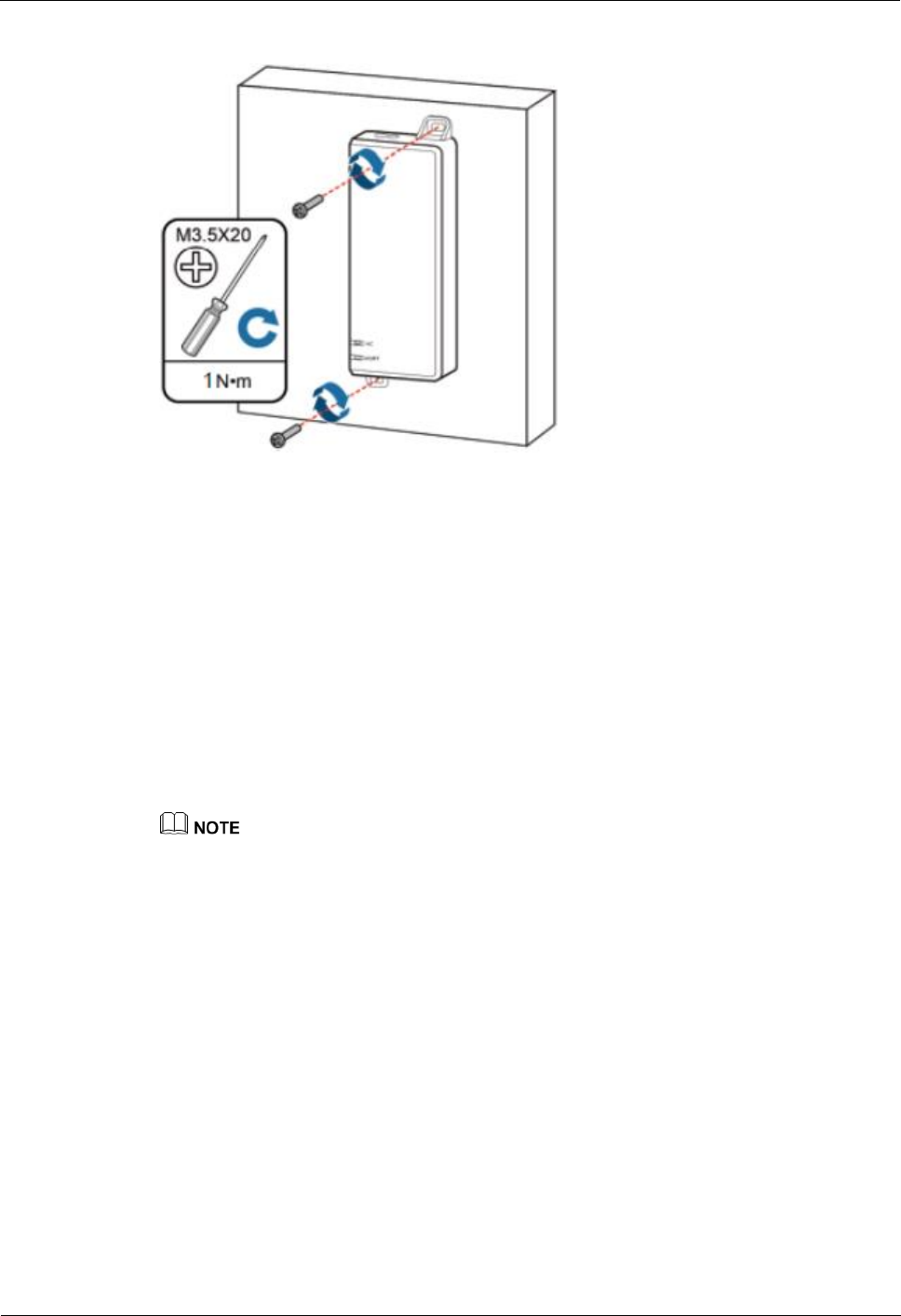
Step 4 Hold the eAN3710A, hang the two dowels on the top of the eAN3710A attachment plate onto
the separate mounting kit, and push the eAN3710A until it snaps into place, as shown by
illustrations a and b in Figure 2-18.
Step 5 Use the M6 inner hexagon screwdriver to tighten the screw on the top of the separate
attachment plate to 5 N·m (61.96 lbf·in.), as shown by illustration c in Figure 2-18.

eAN3710A
Hardware Installation Guide
2 eAN3710A Hardware Installation Guide
Issue 01 (2016-12-26)
Huawei Proprietary and Confidential
Copyright © Huawei Technologies Co., Ltd.
37
Figure 2-18 Securing the eAN3710A onto the mounting kit
----End
2.8 Installing the Auxiliary Devices
This section describes the procedure and precautions for installing the auxiliary devices.
2.8.1 (Optional) Installing a Dock
This section describes the procedure and precautions for installing a dock.
Installing a Dock on a Pole
This section describes the procedure and precautions for installing the Dock on a pole.
Procedure
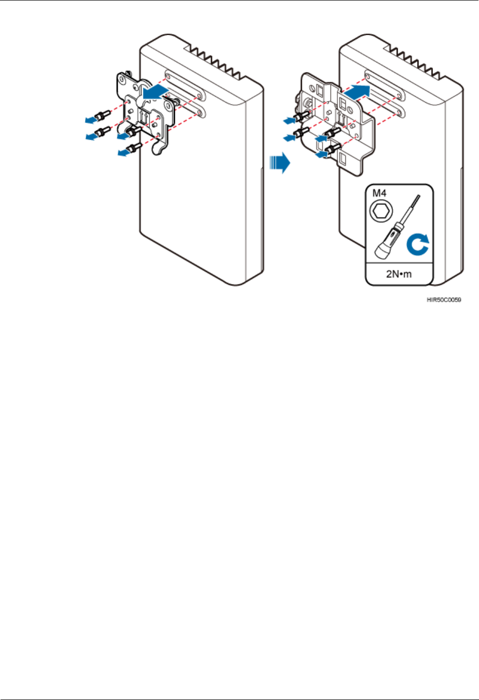
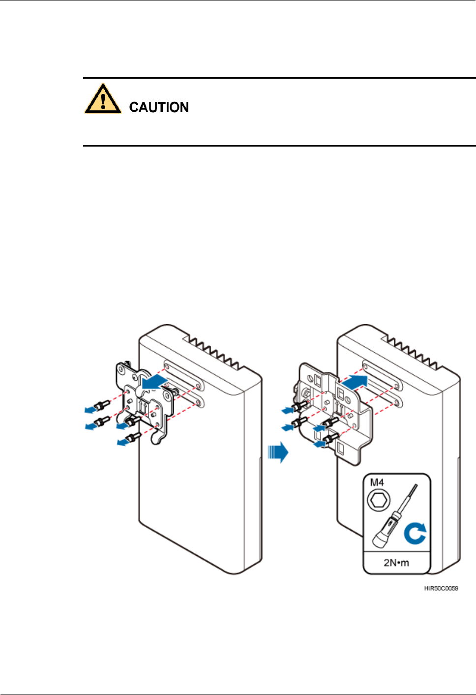
Step 1 Use an M4 inner hexagon screwdriver to remove the Dock integrated mounting bracket,
install the Dock separated mounting bracket instead, and tighten the four screws to 2 N·m
(17.70 lbf·in.), as shown in Figure 2-19.
eAN3710A
Hardware Installation Guide
2 eAN3710A Hardware Installation Guide
Issue 01 (2016-12-26)
Huawei Proprietary and Confidential
Copyright © Huawei Technologies Co., Ltd.
38
Figure 2-19 Replacing the Dock mounting bracket
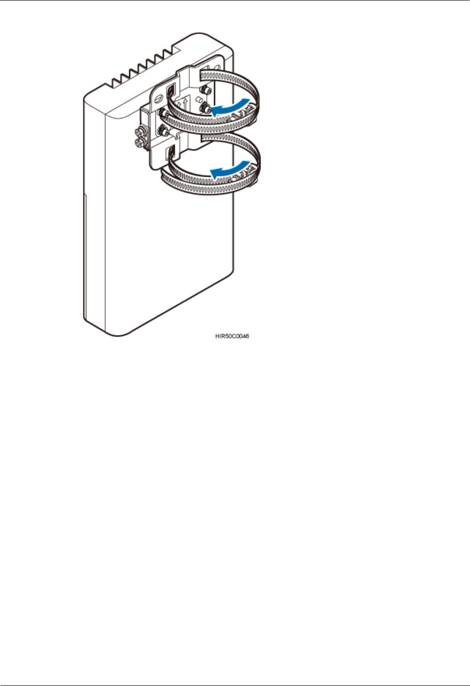
Step 2 Route two hose clamps through the up and down mounting holes on the Dock separate
mounting bracket, but do not route the steel belts through the locks, as shown in Figure 2-20.
eAN3710A
Hardware Installation Guide
2 eAN3710A Hardware Installation Guide
Issue 01 (2016-12-26)
Huawei Proprietary and Confidential
Copyright © Huawei Technologies Co., Ltd.
39
Figure 2-20 Routing hose clamps through the Dock separate mounting bracket
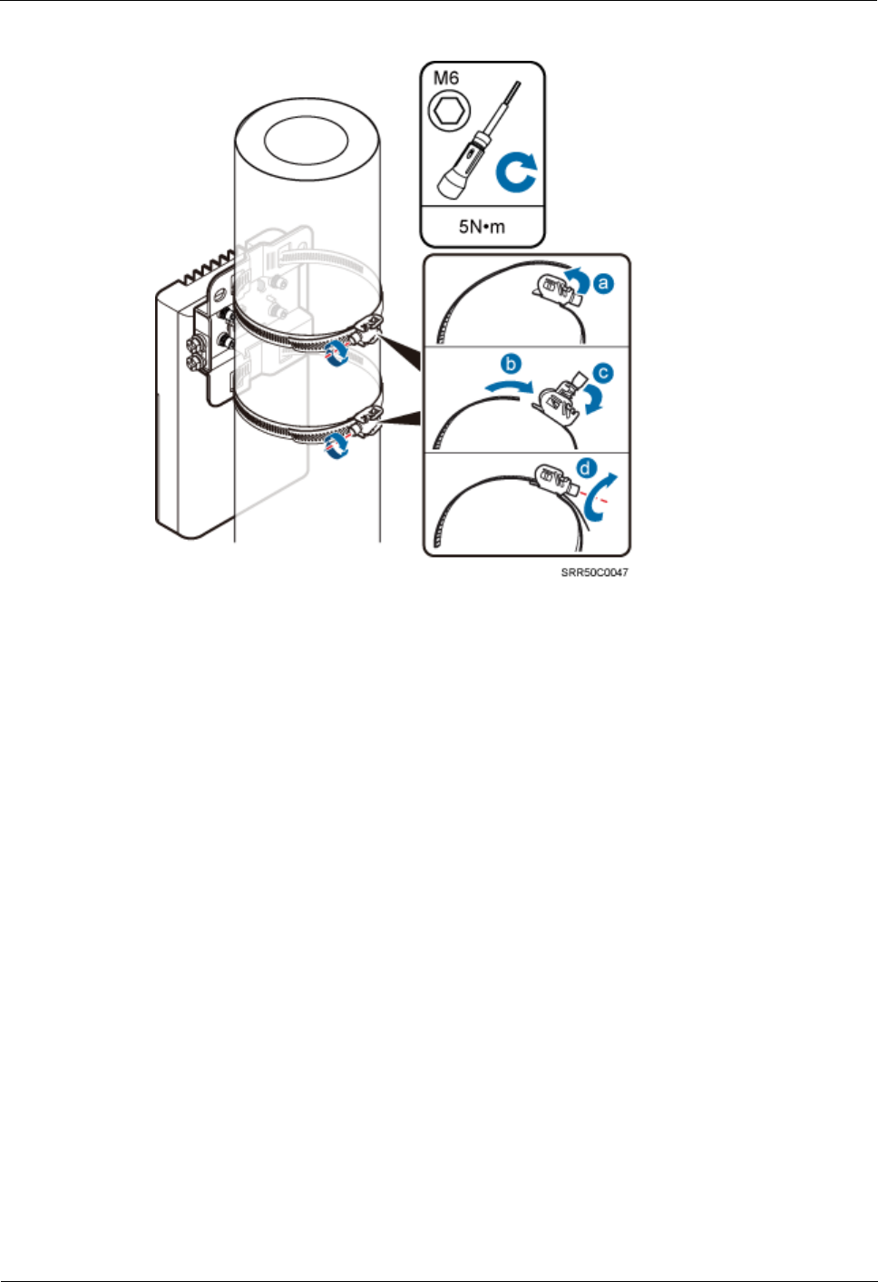
Step 3 Put the Dock in the installation position, route two hose clamps through the pole and the steel
belts through the locking connectors, partially tighten the screws, and use an M6 inner
hexagon torque screwdriver to tighten the screws to 5 N·m (44.25 lbf·in.), as shown in Figure
2-21.
Ensure that your body is close to the module when tightening hose clamps.
eAN3710A
Hardware Installation Guide
2 eAN3710A Hardware Installation Guide
Issue 01 (2016-12-26)
Huawei Proprietary and Confidential
Copyright © Huawei Technologies Co., Ltd.
40
Figure 2-21 Tightening hose clamps
----End
Installing a Dock on a Wall
This section describes the procedure and precautions for installing the Dock on a wall.
Procedure
Step 1 Place the Dock separate mounting bracket against the wall, use a level to verify that the
mounting bracket is horizontally placed, and use a marker to mark anchor points, as shown in
Figure 2-22.
eAN3710A
Hardware Installation Guide
2 eAN3710A Hardware Installation Guide
Issue 01 (2016-12-26)
Huawei Proprietary and Confidential
Copyright © Huawei Technologies Co., Ltd.
41
Figure 2-22 Marking anchor points
(1) Level
(2) Mounting hole
(3) Marker
(4) Dock separate mounting bracket
Step 2 Drill holes at the anchor points, and install expansion bolt assemblies, as shown in Figure
2-23.
Figure 2-23 Drilling holes and installing expansion bolt assemblies
(1) M6x60 bolt
(2) Nut
(3) Spring washer
(4) Flat washer
(5) Expansion tube
eAN3710A
Hardware Installation Guide
2 eAN3710A Hardware Installation Guide
Issue 01 (2016-12-26)
Huawei Proprietary and Confidential
Copyright © Huawei Technologies Co., Ltd.
42
1. Use a hammer drill with a Ф8 drill bit to drill holes perpendicularly with the wall at the
marked anchor points. Ensure that the depth of each hole ranges from 45 mm to 50 mm
(1.77 in. to 1.97 in.) and each hole is of the same depth.
To prevent inhalation or eye contact with dust, take adequate preventive measures when
drilling holes.
2. Use a vacuum cleaner to clear dust inside and around the holes, and then measure the
inter-hole spacing. If the spacing is too wide or too narrow, drill holes again.
3. Tighten each expansion bolt slightly and place them perpendicularly into each hole.
4. Hit each expansion bolt using a rubber mallet to enable the expansion tube to enter the
hole completely.
5. Remove the M6x60 bolt, nut, spring washer, and flat washer from each expansion bolt
assembly in sequence.
Step 3 Use an M4 inner hexagon screwdriver to remove the Dock integrated mounting bracket,
install the Dock separated mounting bracket instead, and tighten the four screws to 2 N·m
(17.70 lbf·in.), as shown in Figure 2-24.
Figure 2-24 Replacing the Dock mounting bracket
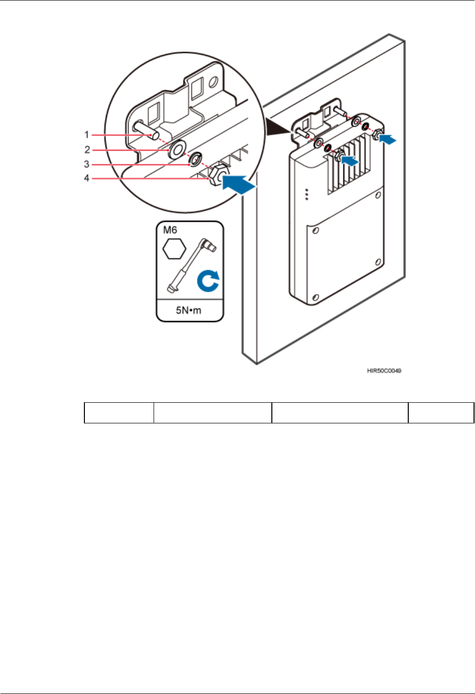
Step 4 Put the Dock to the installation position, install the separate mounting bracket on the
expansion bolts, and use an M6 socket wrench to tighten the expansion bolts to 5 N·m (44.25
lbf·in.), as shown in Figure 2-25.
eAN3710A
Hardware Installation Guide
2 eAN3710A Hardware Installation Guide
Issue 01 (2016-12-26)
Huawei Proprietary and Confidential
Copyright © Huawei Technologies Co., Ltd.
43
Figure 2-25 Fitting the Dock onto the wall
(1) Bolt
(2) Flat washer
(3) Spring washer
(4) Nut
----End
2.8.2 (Optional) Installing the PSE
This section describes the procedure and precautions for installing the PSE on a wall.
Context
The PSE can be installed only on an indoor wall.
Procedure
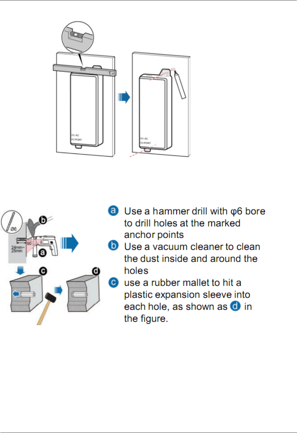
Step 1 Place the PSE against the wall, level it in the installation position, and mark anchor
points.
eAN3710A
Hardware Installation Guide
2 eAN3710A Hardware Installation Guide
Issue 01 (2016-12-26)
Huawei Proprietary and Confidential
Copyright © Huawei Technologies Co., Ltd.
44
Figure 2-26 Marking anchor points
Step 2 Drill holes and install expansion bolts.
Figure 2-27 Drill holes and install expansion bolts
Step 3 Install the PSE
eAN3710A
Hardware Installation Guide
2 eAN3710A Hardware Installation Guide
Issue 01 (2016-12-26)
Huawei Proprietary and Confidential
Copyright © Huawei Technologies Co., Ltd.
45
Figure 2-28 Install the PSE
----End
2.9 Installing eAN3710A Cables
This section describes the procedures for installing eAN3710A cables and auxiliary devices
cables.
2.9.1 Cabling Requirements
Cables must be laid out according to the specified cabling requirements to prevent signal
interference.
If a cable listed below is not required, skip the cabling requirements of the cable.
General Cabling Requirements
Bending radius requirements
The bending radius of a 7/8'' feeder must be greater than 250 mm (9.84 in.), and the
bending radius of a 5/4'' feeder must be greater than 380 mm (14.96 in.).
The bending radius of a 1/4'' jumper must be greater than 35 mm (1.38 in.). The bending
radius of a super-flexible 1/2'' jumper must be greater than 50 mm (1.97 in.), and the
bending radius of an ordinary 1/2'' jumper must be greater than 127 mm (5.00 in.).
The bending radius of a PGND cable must be at least three times its diameter.
The bending radius of a signal cable must be at least five times its diameter.
Cable binding requirements
Cables of the same type must be bound together.
Different types of cables must be separately laid out and bound, with a minimum
distance of 30 mm (1.18 in.) from each other.

eAN3710A
Hardware Installation Guide
2 eAN3710A Hardware Installation Guide
Issue 01 (2016-12-26)
Huawei Proprietary and Confidential
Copyright © Huawei Technologies Co., Ltd.
46
Cables must be bound tightly and neatly. The sheaths of cables must not be damaged.
Cable ties must face the same direction, and those at the same horizontal line must be in
a straight line.
The excess of indoor cable ties must be cut off. The excess of 5 mm (0.197 in.) of
outdoor cable ties should be reserved, and the cut surfaces must be smooth without sharp
edges.
After cables are installed, labels or nameplates must be attached to the cables at their
ends, curves, and interconnection positions.
Security requirements
When laying out cables, avoid sharp objects, for example sharp edges on the wall. If
necessary, use tubes to protect the cables.
When laying out cables, keep cables away from heat sources, or use heat insulation
materials to insulate the cables from the heat sources.
Reserve a proper distance (0.1 m [3.937 in.] is recommended) between equipment and
cables especially at the cable curves to protect the cables and equipment.
Indoor cabling requirements
Route each cable into the room through the feeder window.
Reserve drip loops for all cables outside the feeder window before routing them into the
room. Ensure that the radiuses of the drip loops are greater than or equal to the minimum
bending radiuses of the cables.
When routing a cable into the room, ensure that a person is assisting you in the room.
Apply waterproof treatment to the feeder window.
Outdoor Cabling Requirements
Protect outdoor cables against potential damage. For example, thread the cables through
tubes.
Cables to be protected include AC power cables, transmission cables, and cables laid out
underground.
Use cable clips to secure cables outdoors.
Arrange cables neatly along the routing direction and use cable clips to secure the cables.
Determine the positions where the clips are installed according to the actual situation.
For example, 7/8" feeders are secured with clips at an interval of 1.5 m (4.92 ft) to 2 m
(6.56 ft), and CPRI fiber optic cables and power cables are secured with clips at an
interval of 1 m (3.28 ft) to 1.5 m (4.92 ft). Ensure that the clips are evenly spaced and in
the same direction.
When fastening cables with a clip, ensure that the cables are aligned neatly and are
routed through the holes in the clip. Do not stretch the cables too tightly.
When using clips to secure cables, tighten the screws on the clips after all cables are
arranged and laid out.
Special Cabling Requirements
Cabling of PGND cables
PGND cables for a base station must be connected to the same ground bar.
PGND cables must be buried in the ground or routed indoors.
eAN3710A
Hardware Installation Guide
2 eAN3710A Hardware Installation Guide
Issue 01 (2016-12-26)
Huawei Proprietary and Confidential
Copyright © Huawei Technologies Co., Ltd.
47
The external conductor of the coaxial wire and the shield layer of the shielded cable must
have proper electrical contact with the metal surface of the equipment which they are
connected to.
PGND cables and signal cables must be installed separately. A certain distance must be
reserved between them to prevent interference from each other.
Switches or fuses must not be installed on the PGND cables.
Other devices must not be used for electrical connections of the PGND cables.
All the metal parts in the housing of the equipment must be reliably connected to the
ground terminal.
2.9.2 eAN3710A Cable Connections
This section describes eAN3710A cable connections.
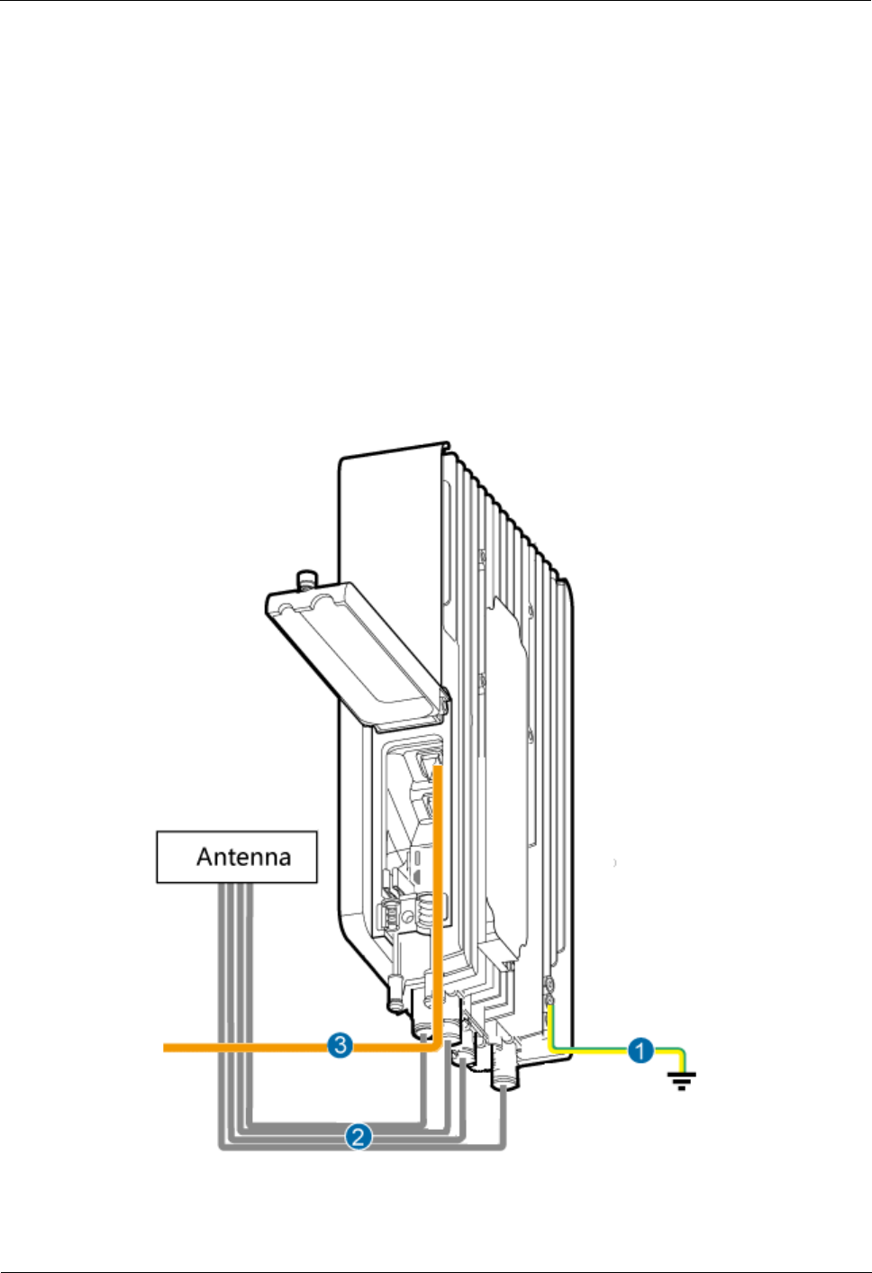
Figure 2-29 shows the cable connections when an eAN3710A is installed.
Figure 2-29 Cable connections when an eAN3710A is installed
eAN3710A
Hardware Installation Guide
2 eAN3710A Hardware Installation Guide
Issue 01 (2016-12-26)
Huawei Proprietary and Confidential
Copyright © Huawei Technologies Co., Ltd.
48
(1) PGND cable
(2) RF jumper
(3) Ethernet cable
2.9.3 Installing a PGND Cable
This section describes the procedure for installing a PGND cable.
Procedure
Step 1 Prepare a eAN3710A PGND cable.
1. Cut the cable to a length suitable for the actual cable route.
2. Add OT terminals to both ends of the cable.
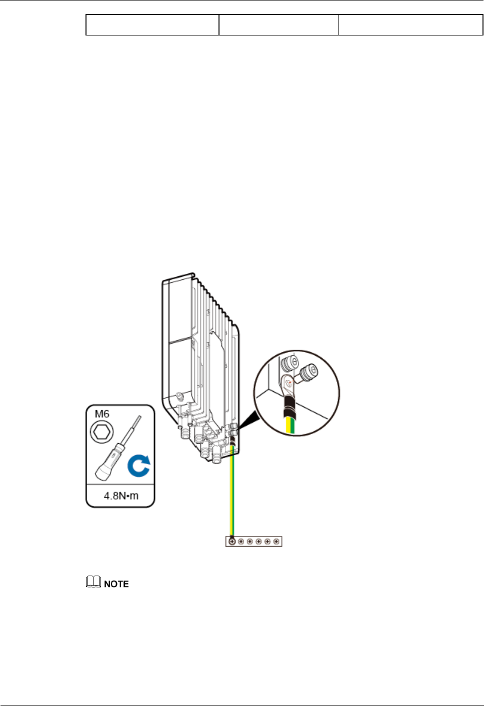
Step 2 Install the eAN3710A PGND cable.
Connect one end of the PGND cable with an M6 OT terminal to the ground terminal at the
eAN3710A bottom and the other end of the cable with an M8 OT terminal to the external
ground bar, as shown in Figure 2-30.
Figure 2-30 Installing a eAN3710A PGND cable
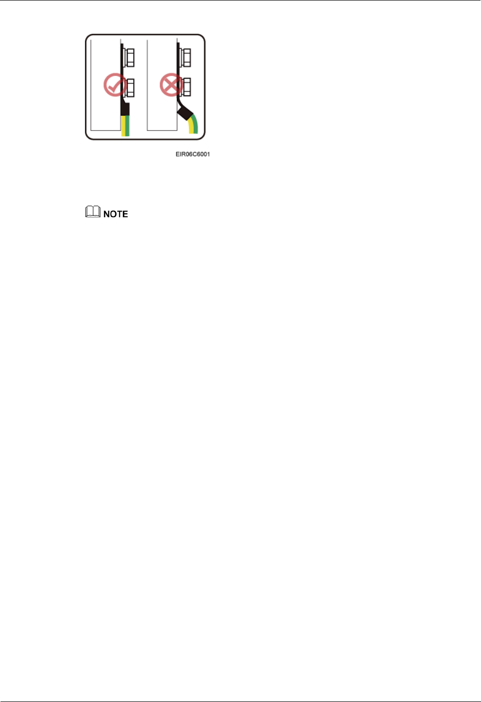
Crimp OT terminals in correct directions, as shown in Figure 2-31.
eAN3710A
Hardware Installation Guide
2 eAN3710A Hardware Installation Guide
Issue 01 (2016-12-26)
Huawei Proprietary and Confidential
Copyright © Huawei Technologies Co., Ltd.
49
Figure 2-31 Correct direction for crimping an OT terminal
Step 3 Label the installed cable.
Follow the same procedure when installing a Dock PGND cable.
----End
2.9.4 Installing a RF Jumper
This section describes the procedure for installing an RF jumper.
Procedure
Step 1 Remove the dustproof cap from the ANT port to be used on the eAN3710A.
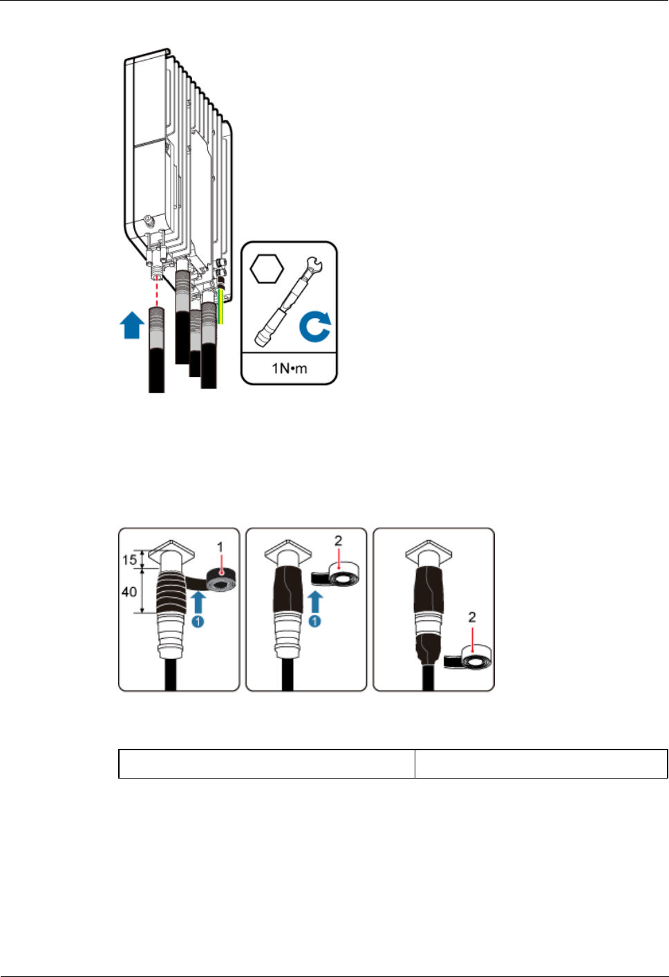
Step 2 Connect the type N male connector at one end of the eAN3710A RF jumper to the ANT port
at the bottom of the eAN3710A in sequence, and use a torque wrench to tighten the connector
to 1 N·m (8.85 lbf·in.), as shown in Figure1.
eAN3710A
Hardware Installation Guide
2 eAN3710A Hardware Installation Guide
Issue 01 (2016-12-26)
Huawei Proprietary and Confidential
Copyright © Huawei Technologies Co., Ltd.
50
Figure 2-32 Installing an RF jumper
Step 3 Connect the other end of the eAN3710A RF jumper to the external antenna system.
Step 4 Waterproof the connector of the RF jumper by waterproof tape, as shown in Figure2.
Figure 2-33 Waterproof the connector of the RF jumper by waterproof tape
(1) PVC insulation tape
(2) Waterproof tape
eAN3710A
Hardware Installation Guide
2 eAN3710A Hardware Installation Guide
Issue 01 (2016-12-26)
Huawei Proprietary and Confidential
Copyright © Huawei Technologies Co., Ltd.
51
During installation, ensure that no foreign substance, including sand, enters the waterproof
tape.
1. Wrap a PVC insulation tape around the exposed area of the connector. The wrapped area
is 15 mm away from the end of the connector, with a total length of 40 mm.
2. Ensure that dimensions (L x W) of the waterproof tape is 50 mm x 50 mm. Stretch the
tape horizontally until it is twice of the original length and wrap it around the upper area
of the connector.
Ensure that the upper end of the waterproof tape overlays that of the PVC insulation
tape.
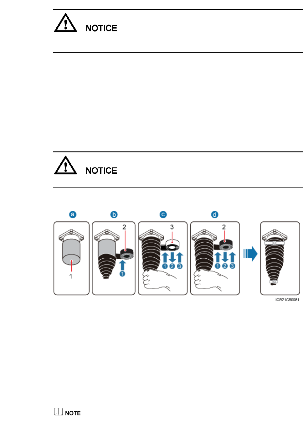
Step 5 Check the dustproof caps on antenna connectors. In outdoor scenarios, dustproof caps must be
waterproofed, as shown in Figure3.
Do not remove dustproof caps from vacant antenna connectors.
Figure 2-34 Waterproofing a dustproof cap
(1) Dustproof cap
(2) PVC insulation tape
(3) Waterproof tape
1. Verify that dustproof caps are not removed.
2. Wrap one layer of PVC insulation tape on each connector from bottom up.
3. Wrap three layers of waterproof tape on each connector, first from bottom up, then from
top down, and finally from bottom up. Wrap each layer of the tape around the connector
tightly.
4. Wrap three layers of PVC insulation tape on each connector, first from bottom up, then
from top down, and finally from bottom up. Wrap each layer of the tape around the
connector tightly.
When wrapping waterproof tape, stretch the tape evenly until it is twice of the original length. When
wrapping PVC insulation tape, do not stretch it.

eAN3710A
Hardware Installation Guide
2 eAN3710A Hardware Installation Guide
Issue 01 (2016-12-26)
Huawei Proprietary and Confidential
Copyright © Huawei Technologies Co., Ltd.
52
Wrap each layer of tape around each connector tightly and neatly, and ensure that the adhesive
surface of each layer of tape overlaps more than 50% of the lower layer.
When cutting off a cable tie, reserve a surplus length of 3 mm (0.12 in.) to 5 mm (0.20 in.).
----End
Follow-up Procedure
1. Route the cable by following the instructions in section cabling requirements and use
cable ties to bind the cable.
2. Label the installed cable.
2.9.5 Installing an eAN3710A Ethernet Cable
This section describes how to install an Ethernet cable.
Context
The Ethernet cable must be of Category 5e (enhanced) or higher. In addition, its
cross-sectional area must be 24 AWG or larger and frame spread rating must be CM or
higher.
Both the cable and the RJ45 connectors are delivered, and they must be prepared onsite.
You need to use a network cable tester to test the Ethernet cable connection.
With the internal PoE module providing power, the maximum length of an Ethernet
cable is 100 m.
Procedure
Step 1 Make the Ethernet cables.
1. Assemble an RJ45 connector and an Ethernet cable.
2. Check whether the made RJ45 connector is qualified.
3. To complete the assembly of the other end, repeat Step 1.1 and Step 1.2.
4. Check whether the touch points on the connectors at both ends are normally conducted
and well contacted and whether the connections are correct.
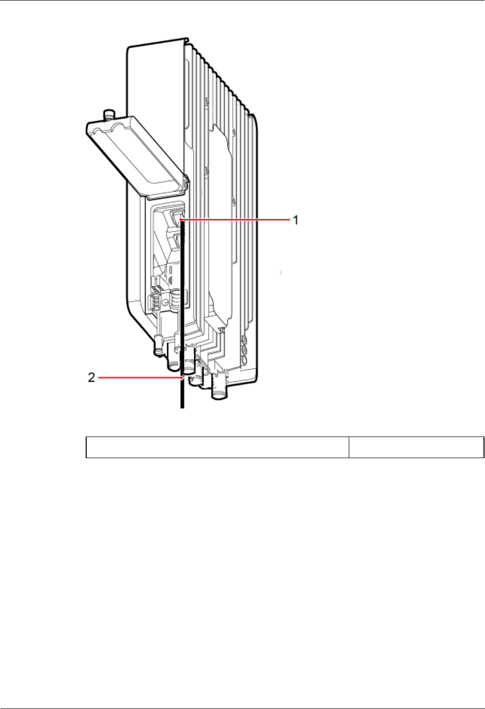
Step 2 Connect the RJ45 connector at one end of the Ethernet cable to the PoE port on the
eAN3710A panel, and push the cables into the cable clips, as shown in Figure 2-35.
eAN3710A
Hardware Installation Guide
2 eAN3710A Hardware Installation Guide
Issue 01 (2016-12-26)
Huawei Proprietary and Confidential
Copyright © Huawei Technologies Co., Ltd.
53
Figure 2-35 Installing an eAN3710A Ethernet cable
(1) PoE port on the eAN3710A panel
(2) Ethernet cable
Step 3 Connect the RJ45 connector at the other end of the Ethernet cable to auxiliary devices port.
----End
Follow-up Procedure
1. Route the cable, and then use a cable tie to bind the cable.
2. Label the installed cable.
2.9.6 (Optional) Installing the PSE Cable
This section describes the procedure and precautions for installing the PSE cables.
Figure 2-36 shows the cable connections when the PSE is installed.
eAN3710A
Hardware Installation Guide
2 eAN3710A Hardware Installation Guide
Issue 01 (2016-12-26)
Huawei Proprietary and Confidential
Copyright © Huawei Technologies Co., Ltd.
54
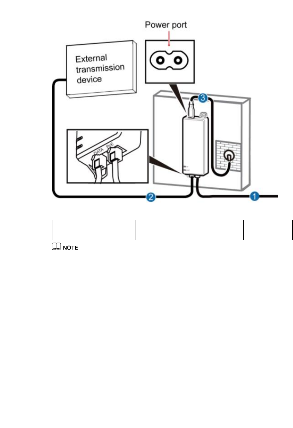
Figure 2-36 Installing the PSE Cable
(1) Ethernet cable between
eAN3710A and PSE
(2) Ethernet cable between PSE and
External transmission device
(3) PSE Power
cable (2m)
The total length of cables connected between the eAN3710A, PSE, and external transmission device
does not exceed 100 m.
2.9.7 (Optional) Installing the Dock Ethernet Cable
This section describes procedure and precautions for installing a Dock Ethernet cable.
Context
The Ethernet cable must be of Category 5e (enhanced) or higher. In addition, its
cross-sectional area must be 24 AWG or larger and frame spread rating must be CM or
higher.
Ethernet cables are not delivered, and they must be prepared onsite. You need to use a
network cable tester to test the Ethernet cable connection.
With the internal PoE module providing power, the maximum length of an Ethernet
cable is 100 m.
Procedure
Step 1 Make the Ethernet cables.
1. Assemble an RJ45 connector and an Ethernet cable.
eAN3710A
Hardware Installation Guide
2 eAN3710A Hardware Installation Guide
Issue 01 (2016-12-26)
Huawei Proprietary and Confidential
Copyright © Huawei Technologies Co., Ltd.
55
2. Check whether the made RJ45 connector is qualified.
3. To complete the assembly of the other end, repeat Step 1.1 and Step 1.2.
4. Check whether the touch points on the connectors at both ends are normally conducted
and well contacted and whether the connections are correct.
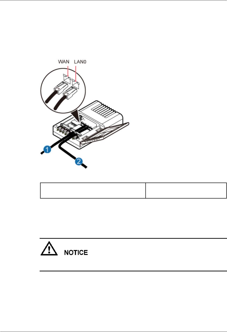
Step 2 Installing the Dock Ethernet cable, as shown in Figure 2-37.
Figure 2-37 Installing the Dock Ethernet cable
(1) Ethernet cable between Dock and external
transmission device
(2) Ethernet cable between
eAN3710A and Dock
1. Connect one end of the assembled Ethernet cable to the WAN port in the cabling cavity
of the Dock and the other end to the external transmission device.
2. Connect the other end of the Ethernet cable, which is connected to the PoE port on the
eAN3710A, to the LAN0 port in the cabling cavity of the Dock.
The eAN3710A must be connected to the LAN0 port on the Dock. Otherwise, you are not
able to maintain the eAN3710A remotely.
----End
2.9.8 (Optional) Installing the Dock Power Cable
This section describes the procedure and precautions for installing a power cable. A Dock
input power cable connects the Dock and an external power supply device to lead external
eAN3710A
Hardware Installation Guide
2 eAN3710A Hardware Installation Guide
Issue 01 (2016-12-26)
Huawei Proprietary and Confidential
Copyright © Huawei Technologies Co., Ltd.
56
power into the Dock. A Dock cascading power cable is used for power supply cascading
between two Docks.
Context
Table 2-3 lists the specifications of the two power cables.
Table 2-3 Power cable specifications
Cable
Color
One End
The Other End
Dock input
power cable
L
Brown
Cord end
terminal (1.5
mm2)
Depends on the
external power
device
N
Blue
Cord end
terminal (1.5
mm2)
Depends on the
external power
device
PE
Yellow and
green
Cord end
terminal (1.5
mm2)
Depends on the
external power
device
Dock cascading
power cable
L
Brown
Cord end
terminal (1.5
mm2)
Cord end
terminal (1.5
mm2)
N
Blue
Cord end
terminal (1.5
mm2)
Cord end
terminal (1.5
mm2)
PE
Yellow and
green
Cord end
terminal (1.5
mm2)
Cord end
terminal (1.5
mm2)
The color and structure of the power cables differ in different countries and regions. The power cables
purchased locally must conform to the local standards.
Procedure
Step 1 Make power cables.
1. Cut the cable to a length suitable for the actual cable route.
2. Add an OT terminal to one end of the cable, and add the corresponding power terminal
to the other end according to external power supply device.
3. Optional: Add an OT terminal to each end of the Dock cascading power cable.
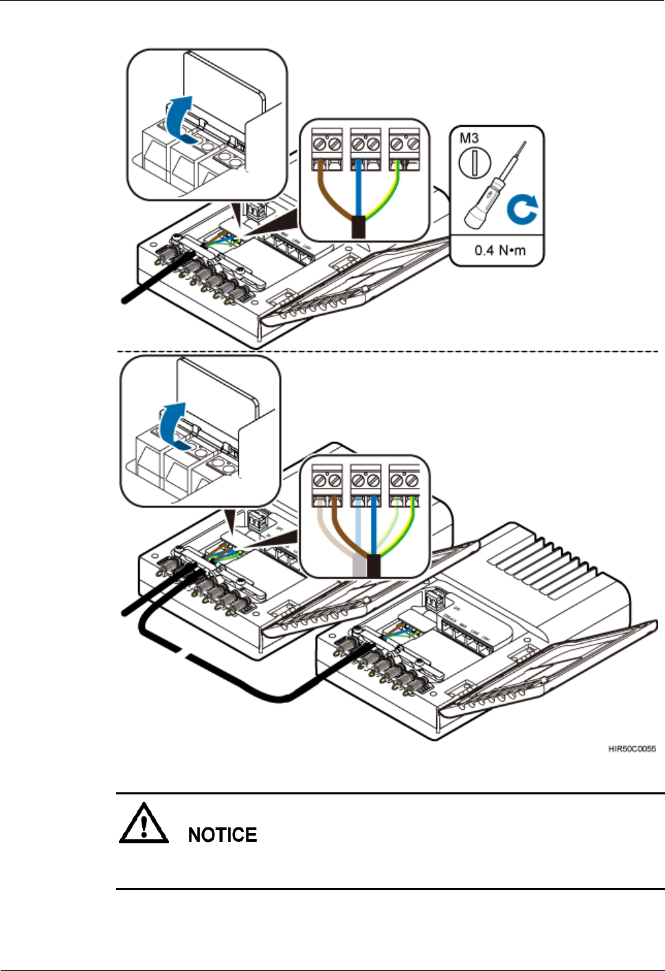
Step 2 Install power cables, as shown in Figure 2-38.
1. Open the protective cover of the power supply terminal.
2. Install Dock input power cables.

eAN3710A
Hardware Installation Guide
2 eAN3710A Hardware Installation Guide
Issue 01 (2016-12-26)
Huawei Proprietary and Confidential
Copyright © Huawei Technologies Co., Ltd.
57
Use a flat-head screwdriver to loosen the left ports on the L, N, and PE wiring posts
inside the Dock. Connect one end of each cable to the corresponding port on the left side
and tighten the wiring posts. Connect the other end to external devices.
3. Optional: Install Dock cascading power cables.
Use a flat-head screwdriver to loosen the right ports on the L, N, and PE wiring posts
inside one Dock. Connect one end of each cable to the corresponding port on the right
side and tighten the wiring posts. Connect the other end of cables to corresponding ports
on the L, N, or PE wiring posts inside the lower-level cascaded Dock.
4. Restore the protective cover of the power supply terminal.
eAN3710A
Hardware Installation Guide
2 eAN3710A Hardware Installation Guide
Issue 01 (2016-12-26)
Huawei Proprietary and Confidential
Copyright © Huawei Technologies Co., Ltd.
58
Figure 2-38 Installing power cables
The protective cover of the power supply terminal is automatically secured. After the
procedure is complete, tap the protective cover to restore it.
----End
eAN3710A
Hardware Installation Guide
2 eAN3710A Hardware Installation Guide
Issue 01 (2016-12-26)
Huawei Proprietary and Confidential
Copyright © Huawei Technologies Co., Ltd.
59
2.10 Checking the eAN3710A Hardware Installation
eAN3710A hardware installation checking includes hardware and cable installation checking.
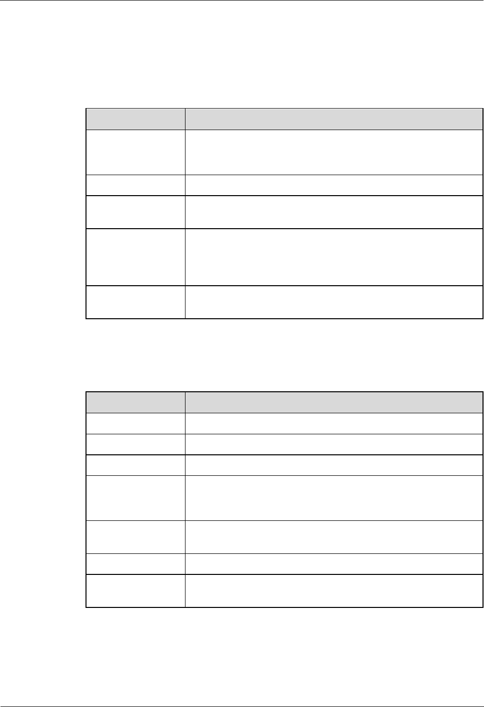
Table 2-4 lists the hardware installation checking items.
Table 2-4 Hardware installation checking list
No.
Item
1
The installation position of each device strictly complies with the
engineering design and meets clearance requirements. Sufficient
space is reserved for equipment maintenance.
2
The eAN3710A is securely installed.
3
The cover plate is securely installed on the eAN3710A cabling
cavity.
4
Waterproof blocks are securely installed in vacant cable troughs of
the eAN3710A cabling cavity, and the cover plate of the cabling
cavity is securely installed. In addition, vacant RF ports are covered
with dustproof caps and the caps are tightened.
5
Labels are correct, legible, and complete at both ends of each cable,
feeder, and jumper.
Table 2-5 lists the check items of the signal cable connection.
Table 2-5 Checklist for the signal cable connection
No.
Item
1
The connectors of the signal cables must securely connected.
2
The connectors of the signal cables are intact.
3
The signal cables are intact.
4
The cable ties are evenly spaced. The signal cables are bound neatly
with cable ties to proper tightness, and arranged at even intervals in
the same direction.
5
The extra length of the cable ties is cut and removed. The cut
surfaces of the indoor cables are smooth and have no sharp edges.
6
The cable layout facilitates maintenance and expansion.
7
Correct and clear labels are attached to both ends of the signal
cables.
Table 2-6 lists the checking items for other cable connections.
eAN3710A
Hardware Installation Guide
2 eAN3710A Hardware Installation Guide
Issue 01 (2016-12-26)
Huawei Proprietary and Confidential
Copyright © Huawei Technologies Co., Ltd.
60
Table 2-6 Checklist for other cable connections
No.
Item
1
The connectors of the other cables must securely connected.
2
Labels on the cables are legible and bound based on the engineering
requirements. The cables must be bound tightly and neatly. The
sheaths of the cables must not be damaged.
3
Positions for routing the cables must meet requirements of the
engineering design.
4
There are no connectors or joints on each PGND cable. None of
PGND cables can be short-circuited or reversely connected. In
addition, these cables are not damaged or broken.
5
PGND cables are separately bound from other cables.
6
The protection grounding of the eAN3710A and the surge
protection grounding of the building share one group of ground
conductors.
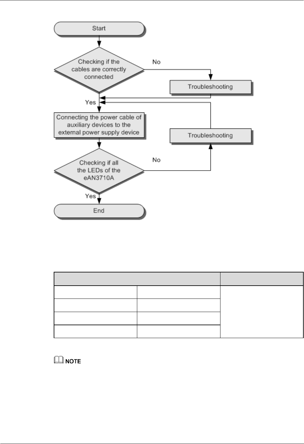
2.11 Power-On Check on the eAN3710A
This section describes the procedure for performing a power-on check on the eAN3710A.
eAN3710A Power-On Check Procedure
After you unpack a eAN3710A, you must power on it within 24 hours. If you power off the
eAN3710A for maintenance, you must restore power to it within 24 hours.
Figure 2-39 shows the eAN3710A power-on check procedure.
eAN3710A
Hardware Installation Guide
2 eAN3710A Hardware Installation Guide
Issue 01 (2016-12-26)
Huawei Proprietary and Confidential
Copyright © Huawei Technologies Co., Ltd.
61
Figure 2-39 Power-on check procedure
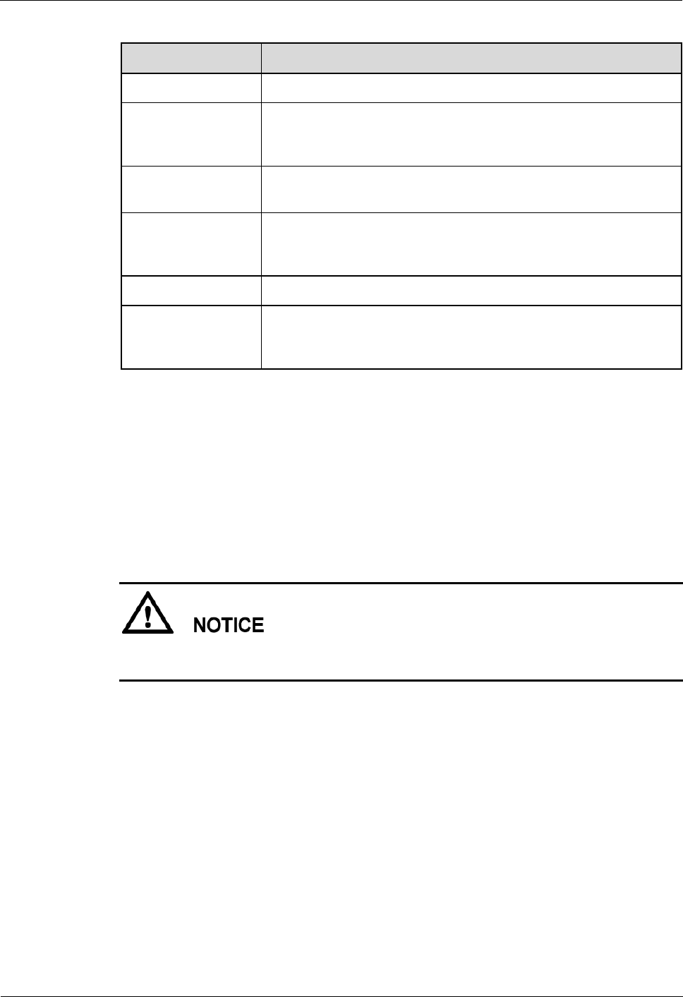
Checking the Indicator Status
Table 2-7 Checking the indicator status
If...
then...
RUN
Steady white
The eAN3710A is running
correctly.
ETH
Blinking white
WIFI
Off
LINK
Off
During the eAN3710A startup, there is no need to observe the indicator status.
During a start, the eAN3710A reads and writes the flash and therefore the indicators blinking
quickly may blink irregularly for 1-2 seconds, which does not affect services.
eAN3710A
Hardware Installation Guide
2 eAN3710A Hardware Installation Guide
Issue 01 (2016-12-26)
Huawei Proprietary and Confidential
Copyright © Huawei Technologies Co., Ltd.
62
2.12 Appendix
This section describes reference information during installation.
2.12.1 ESN Collection Template
This section describes the eAN3710A ESN collection template.
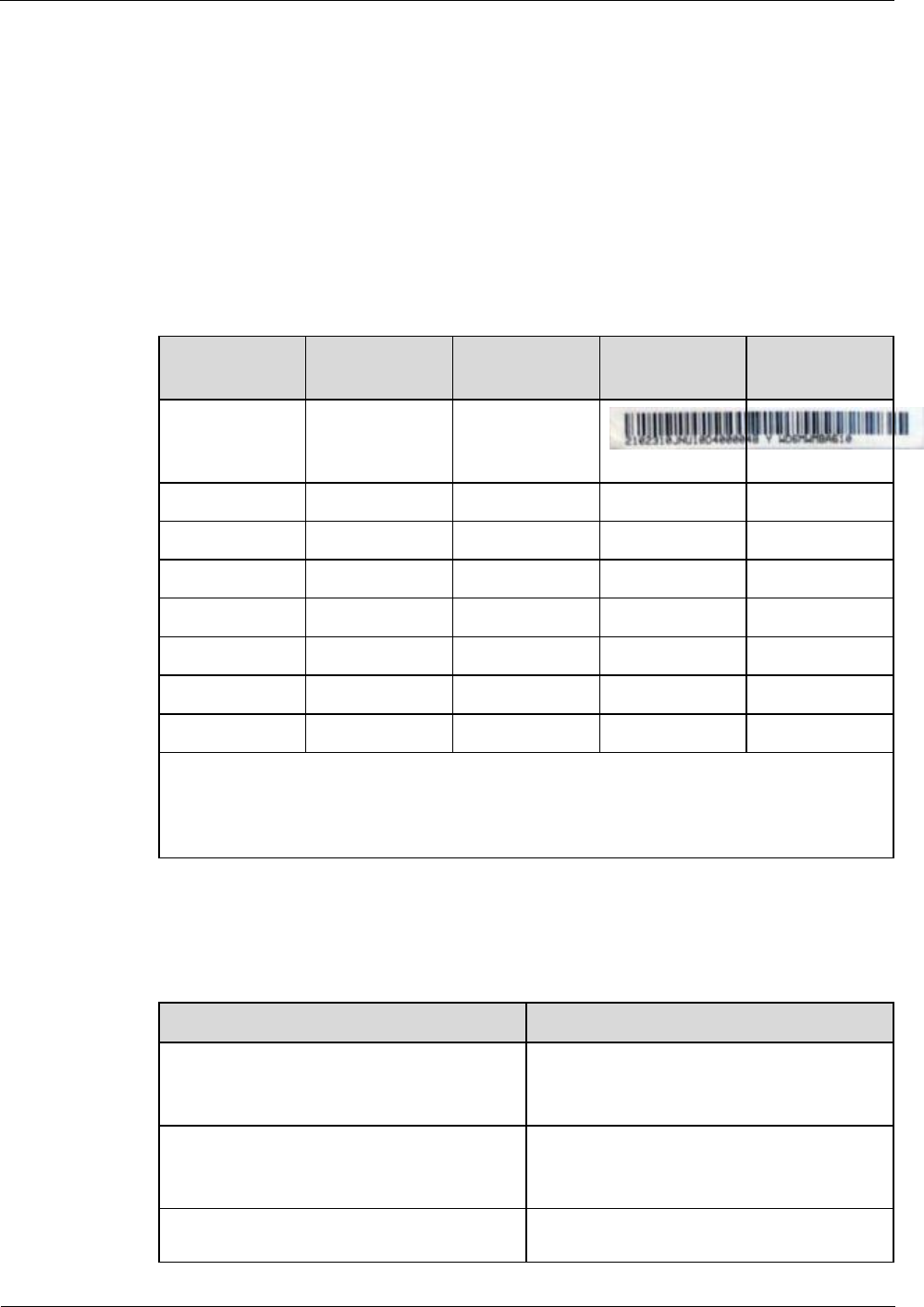
The ESN collection template is used to record the installation position, and ESN of the site at
the initial installation stage to facilitate subsequent commissioning and maintenance. Table
2-8 shows the ESN collection template.
Table 2-8 ESN collection template
No.
Site Number
Site Name
Base Station
ESN
Location
Information
Sample
xx
eAN_1
xx floor, xx
building, xx
mansion
Note: The ESN collection template is essential to the engineering stage and subsequent
maintenance, especially when multiple devices are installed at a short distance. This is
because the template defines the radio network to access. Please maintain this
template with caution.
2.12.2 Antenna Installation
This section describes the reference documents for installing the antenna system.
Related Document
Description
Antenna System (on Tower) Quick
Installation Guide
This document describes the installation
procedure and manhour requirements of the
antenna system.
Antenna System (on Roof Pole) Quick
Installation Guide
This document describes the installation
procedures and methods of the antenna
system on roof pole.
GPS Satellite Antenna System Quick
This document describes the installation
procedures and methods of the GPS antenna