Huawei Technologies EAN3810A eLTE-U Airnode User Manual Deployment Guide
Huawei Technologies Co.,Ltd eLTE-U Airnode Deployment Guide
UserManual.wiki
>
Huawei Technologies
>
EAN3810A User Manual
>
Deployment Guide
Contents
1.
Users Manual
2.
Deployment Guide
3.
Hardware Installation Guide
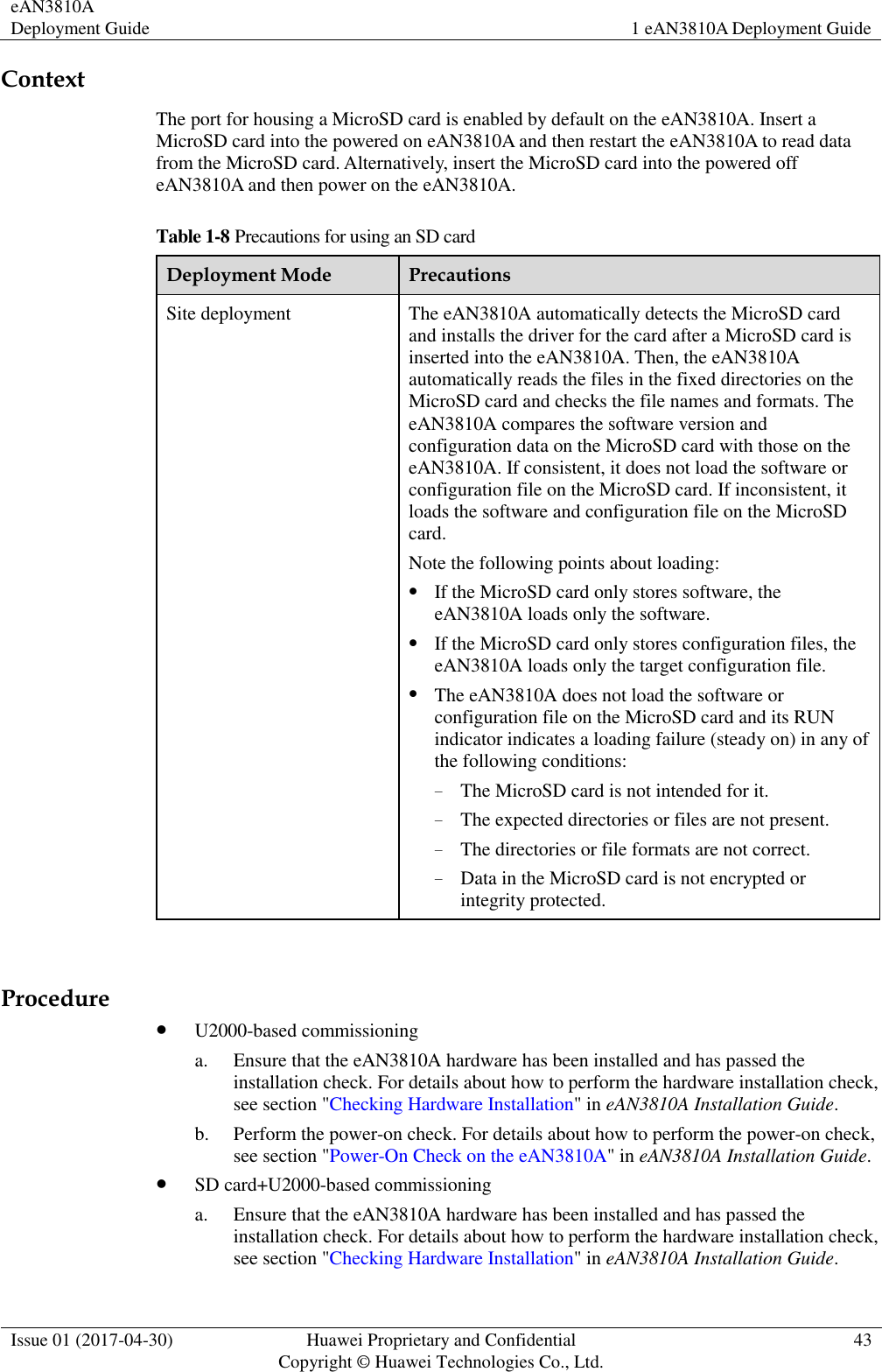
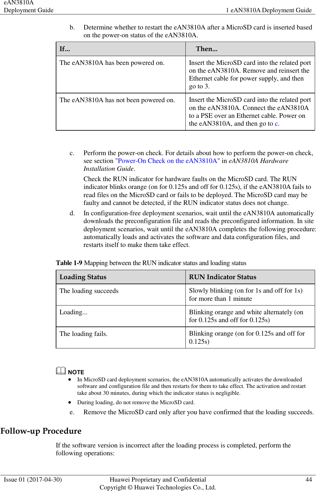
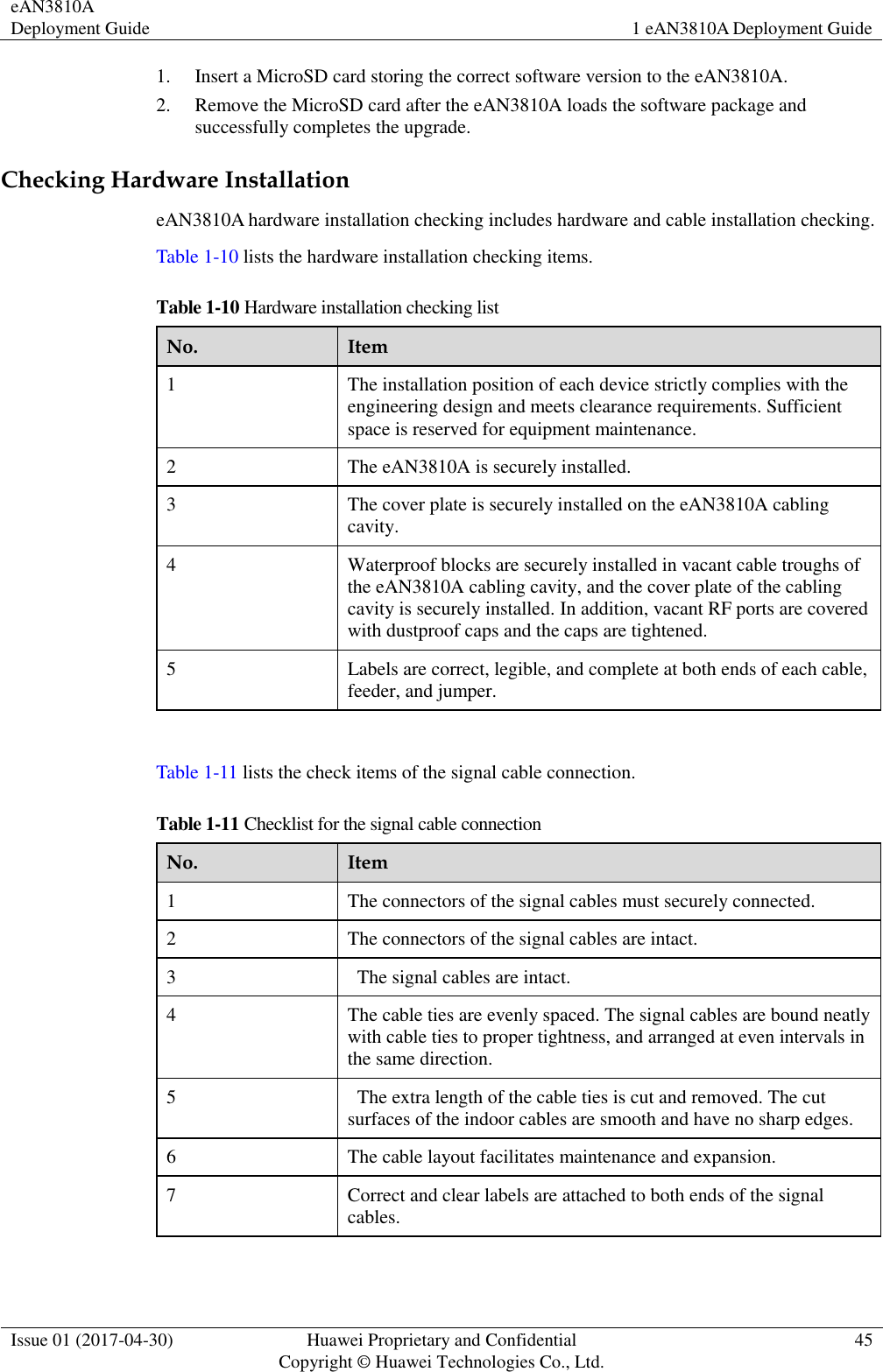
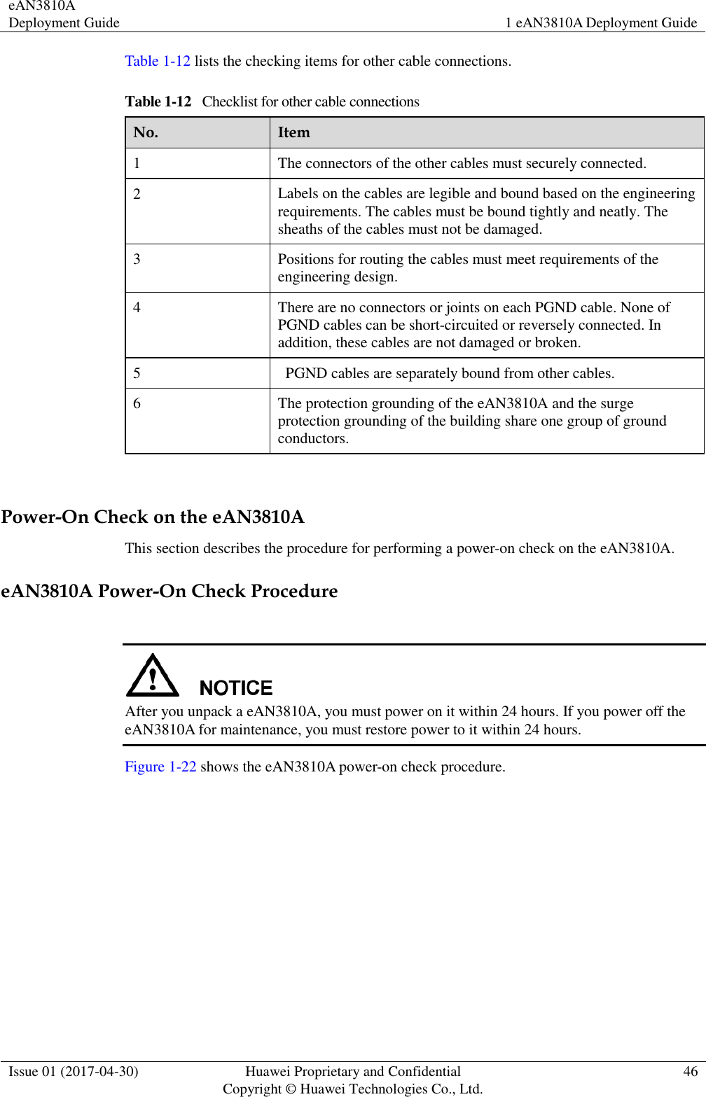
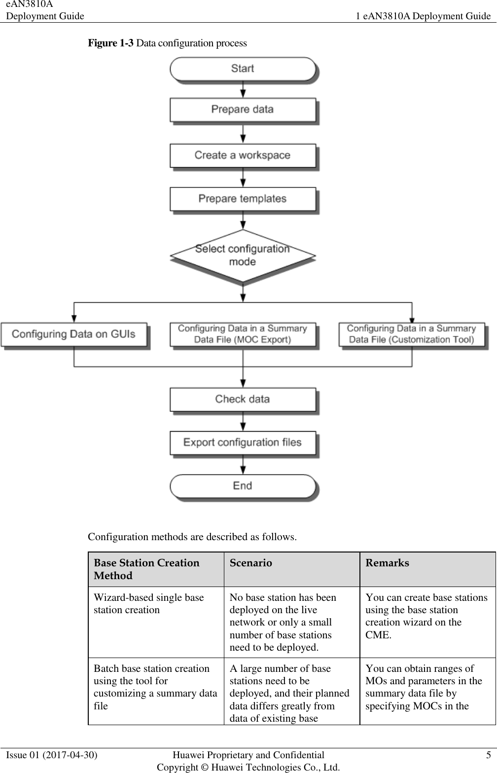
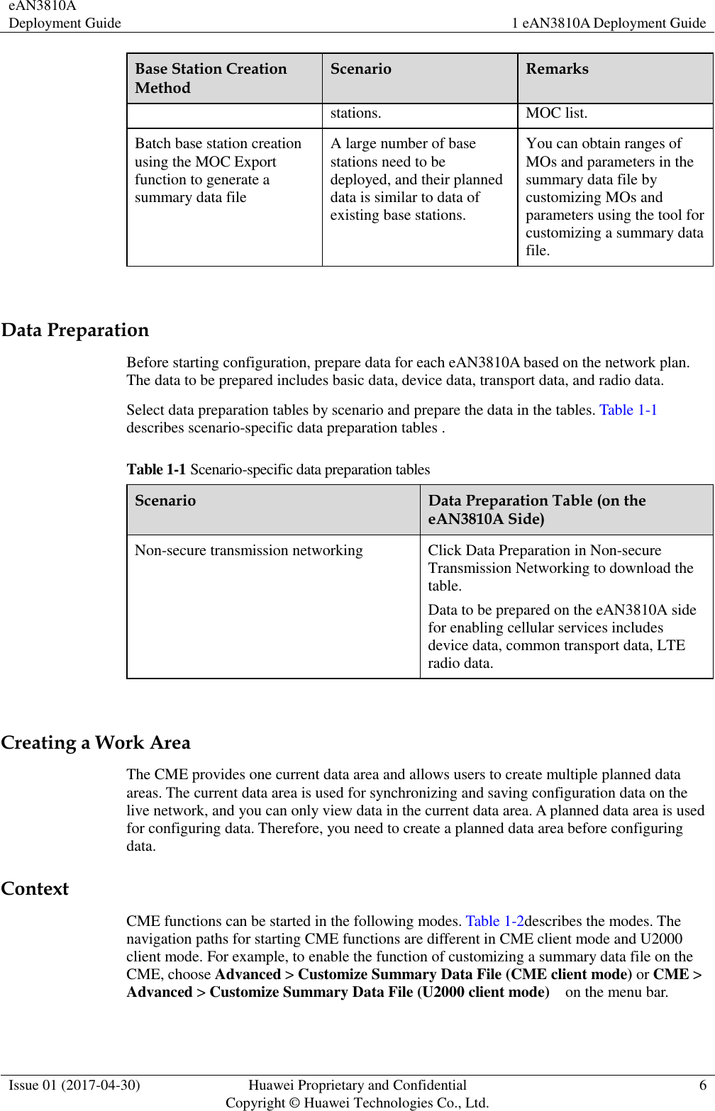
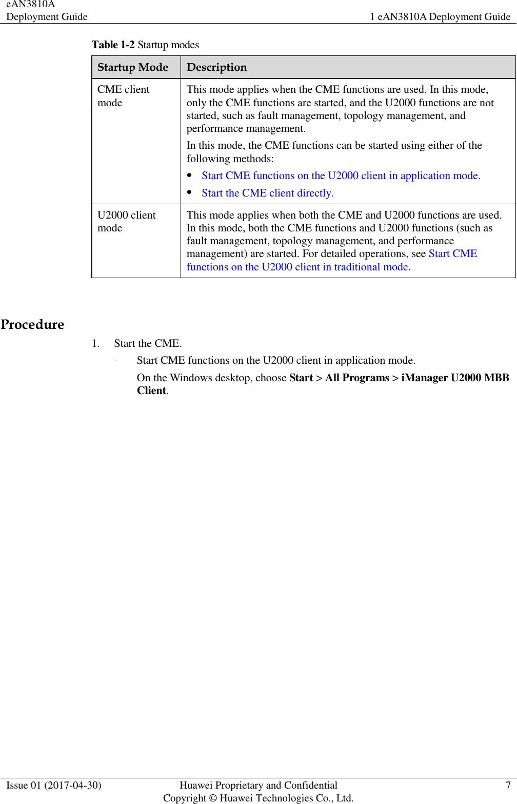
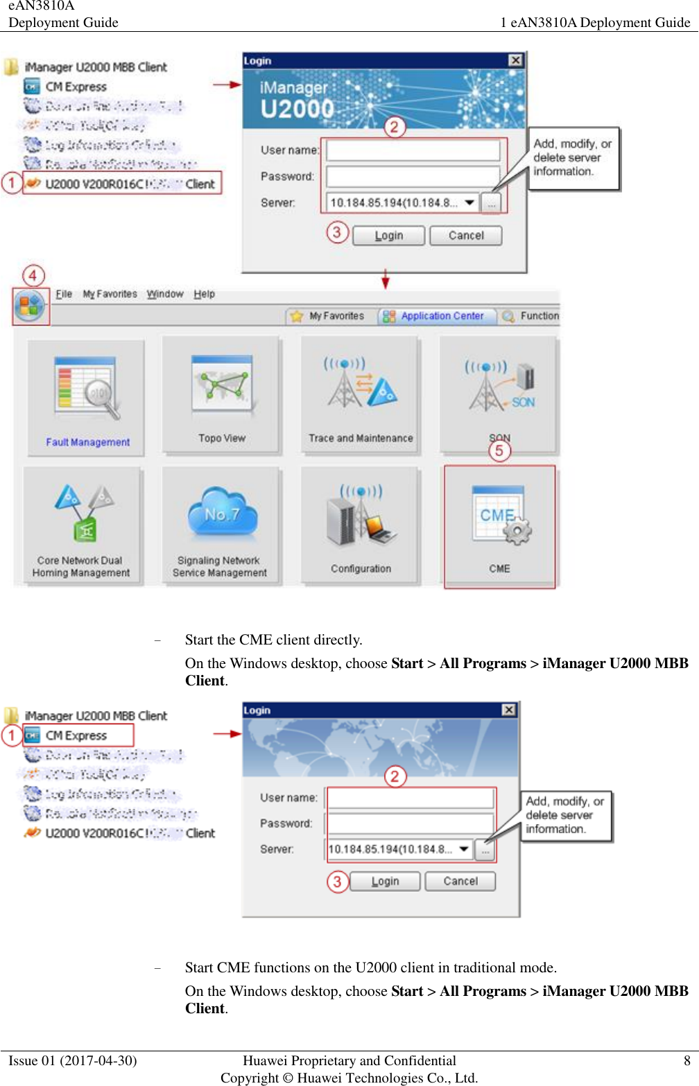
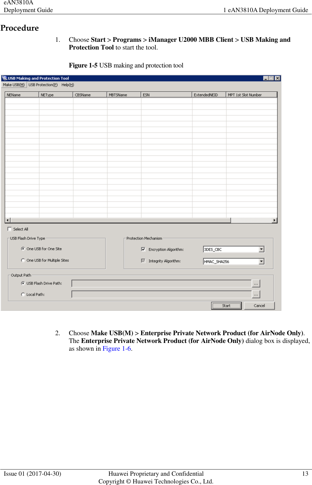
Deployment Guide
Navigation menu
Upload a User Manual
Namespaces
Wiki Guide
HTML
PDF
Info
Views
User Manual
Discussion / Help
Navigation
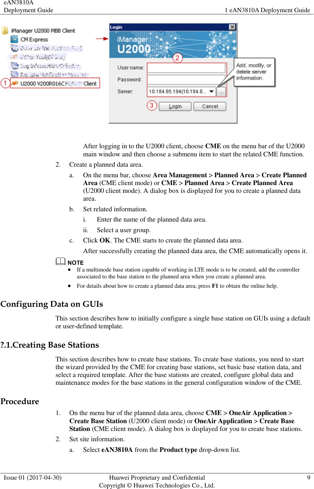
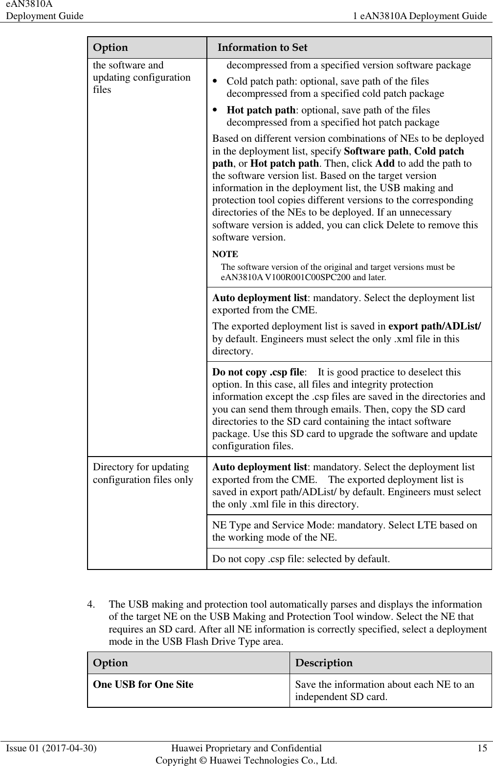
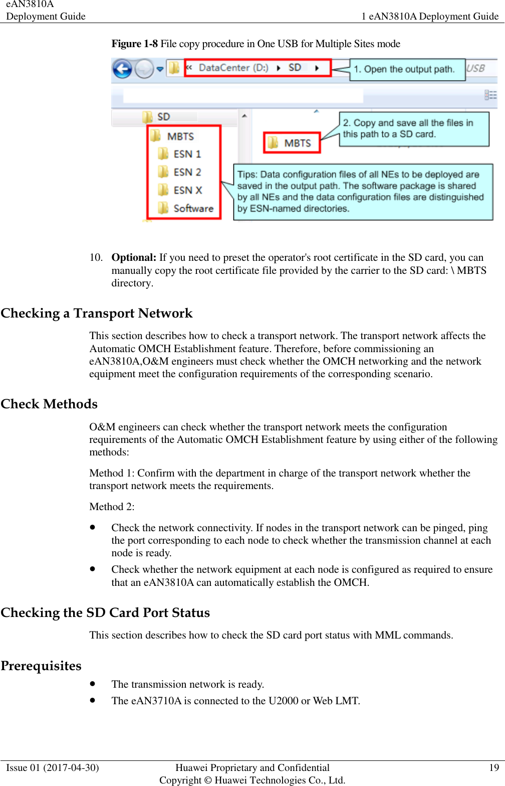
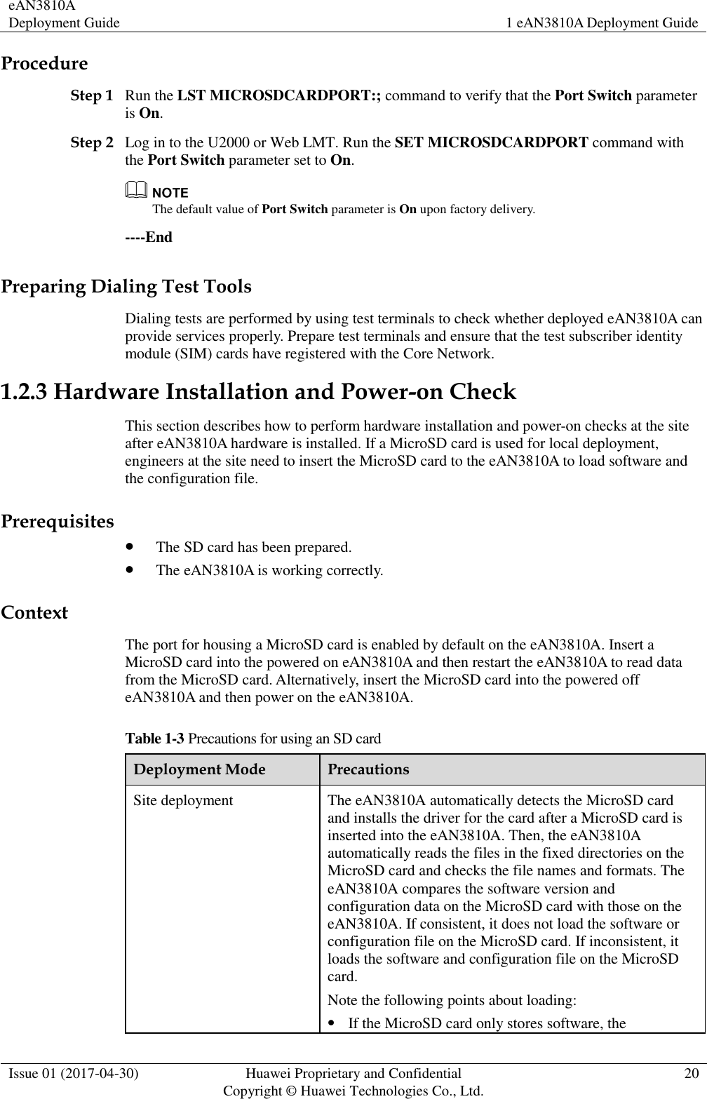
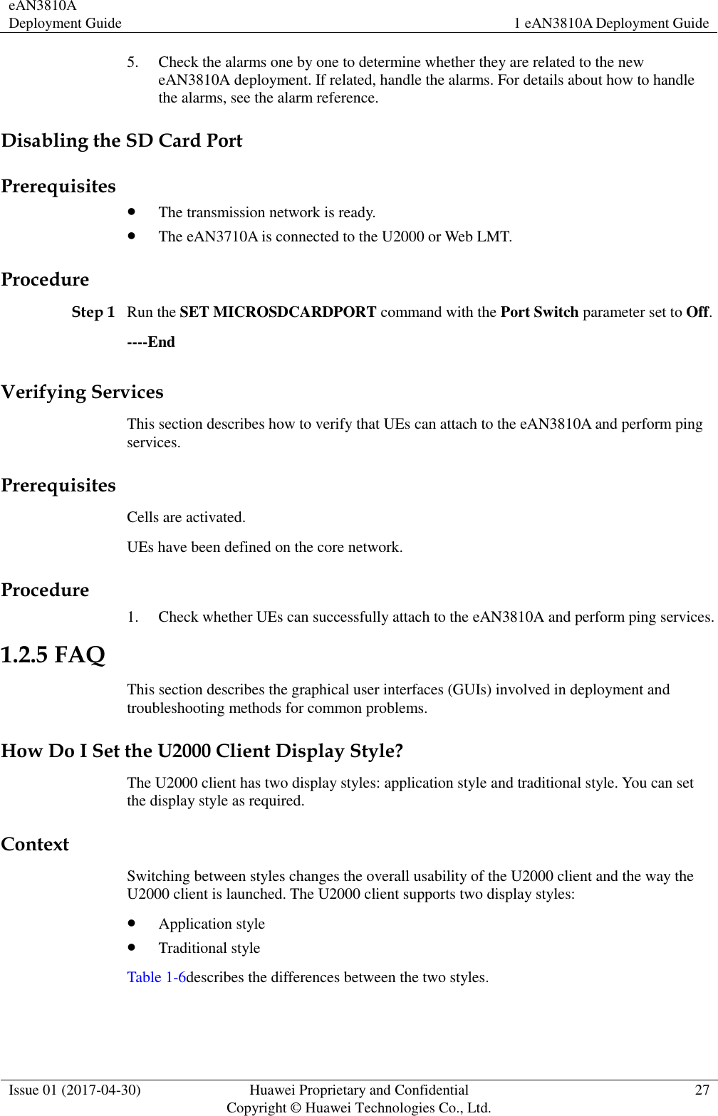
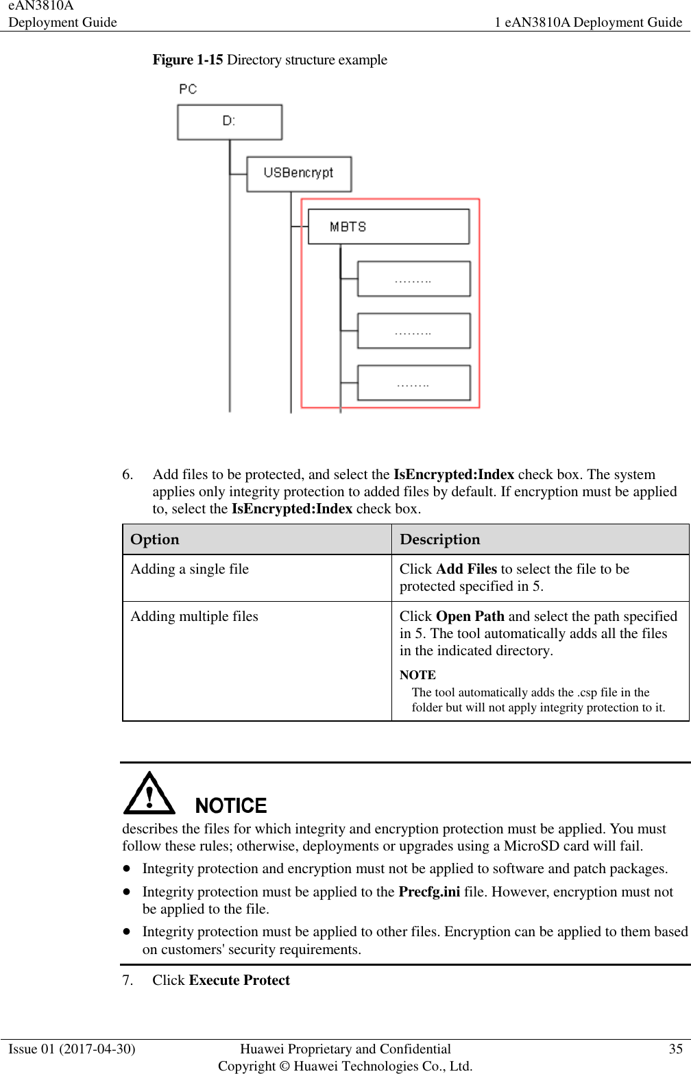
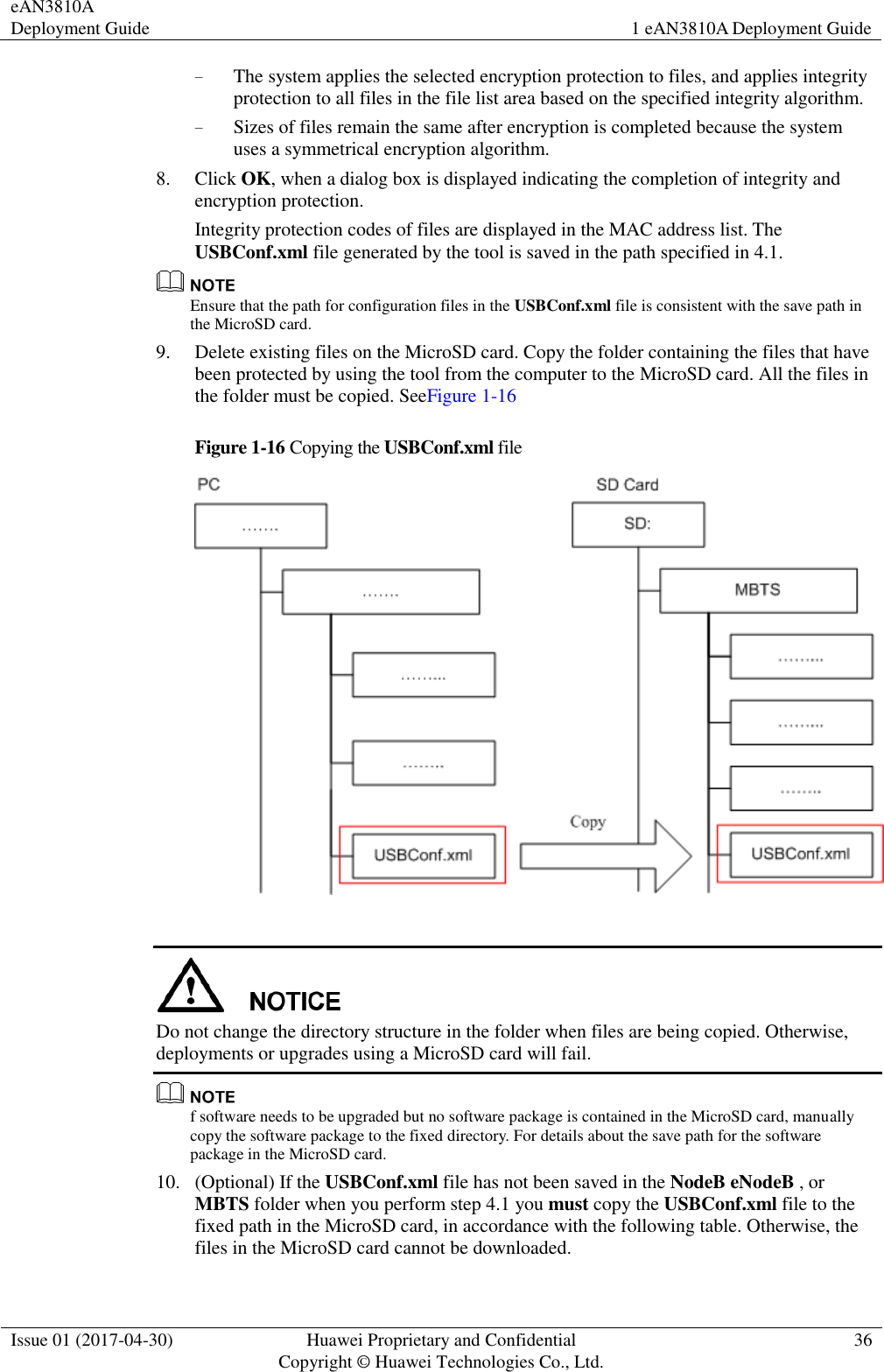
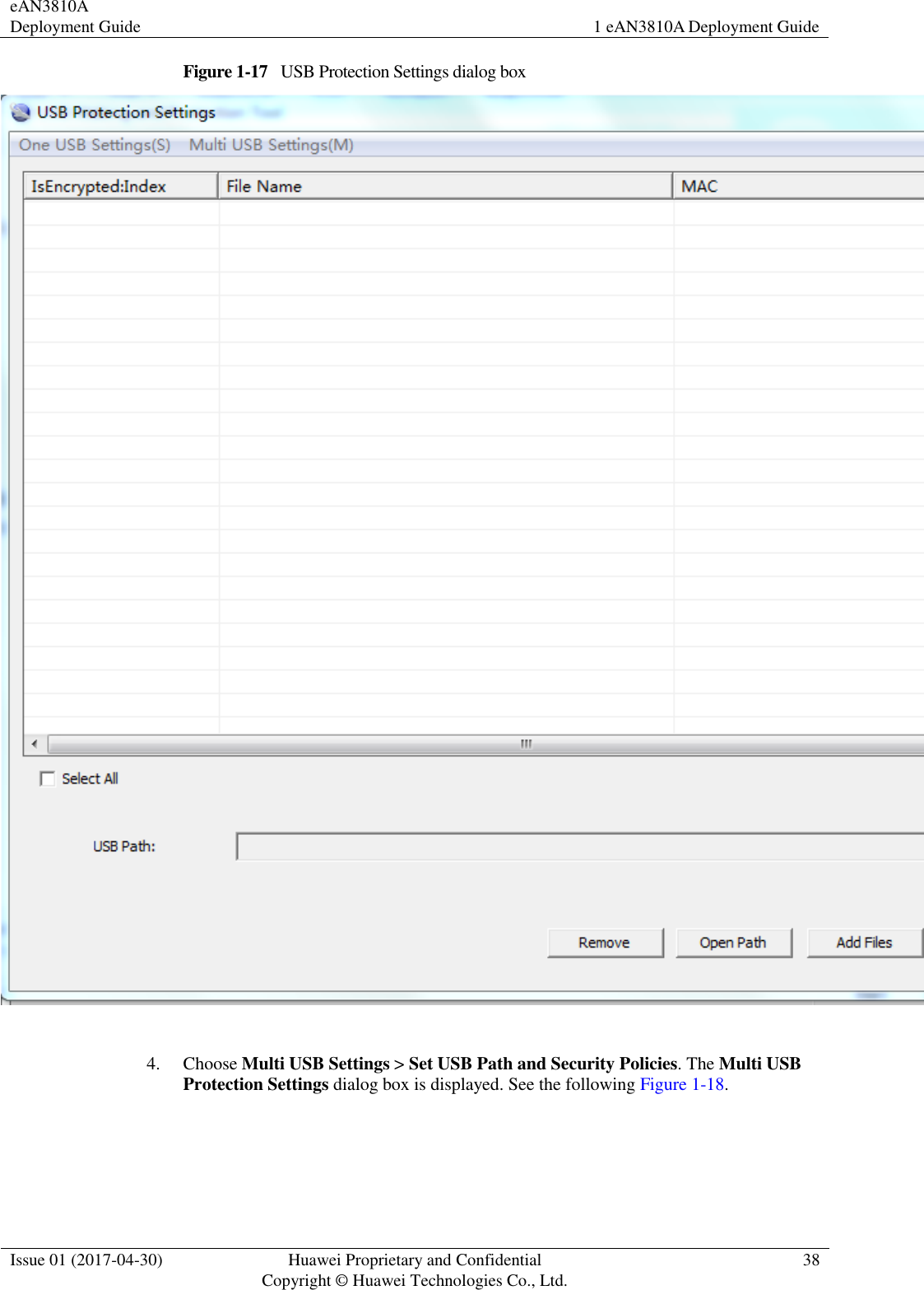
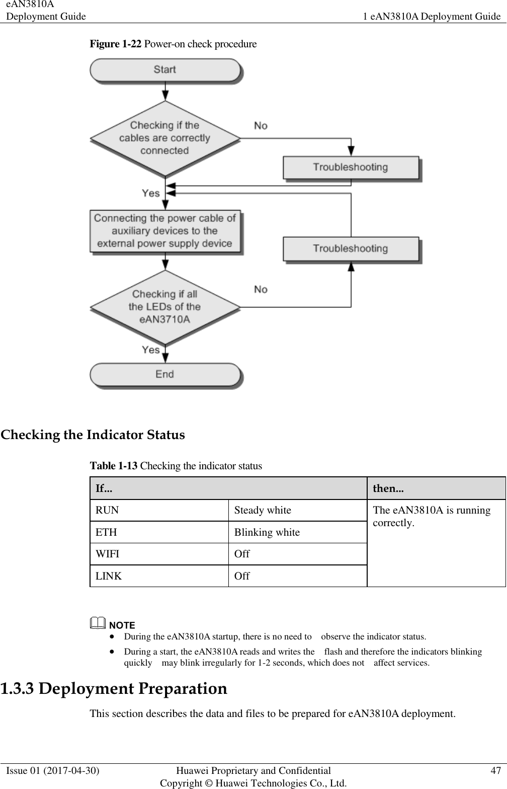
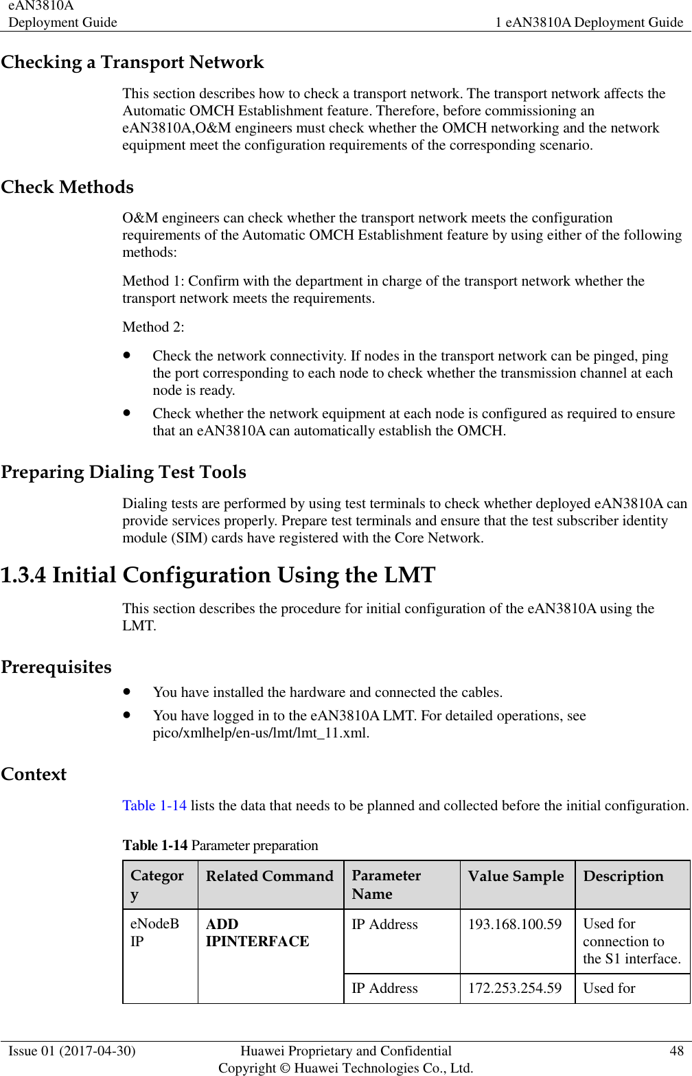
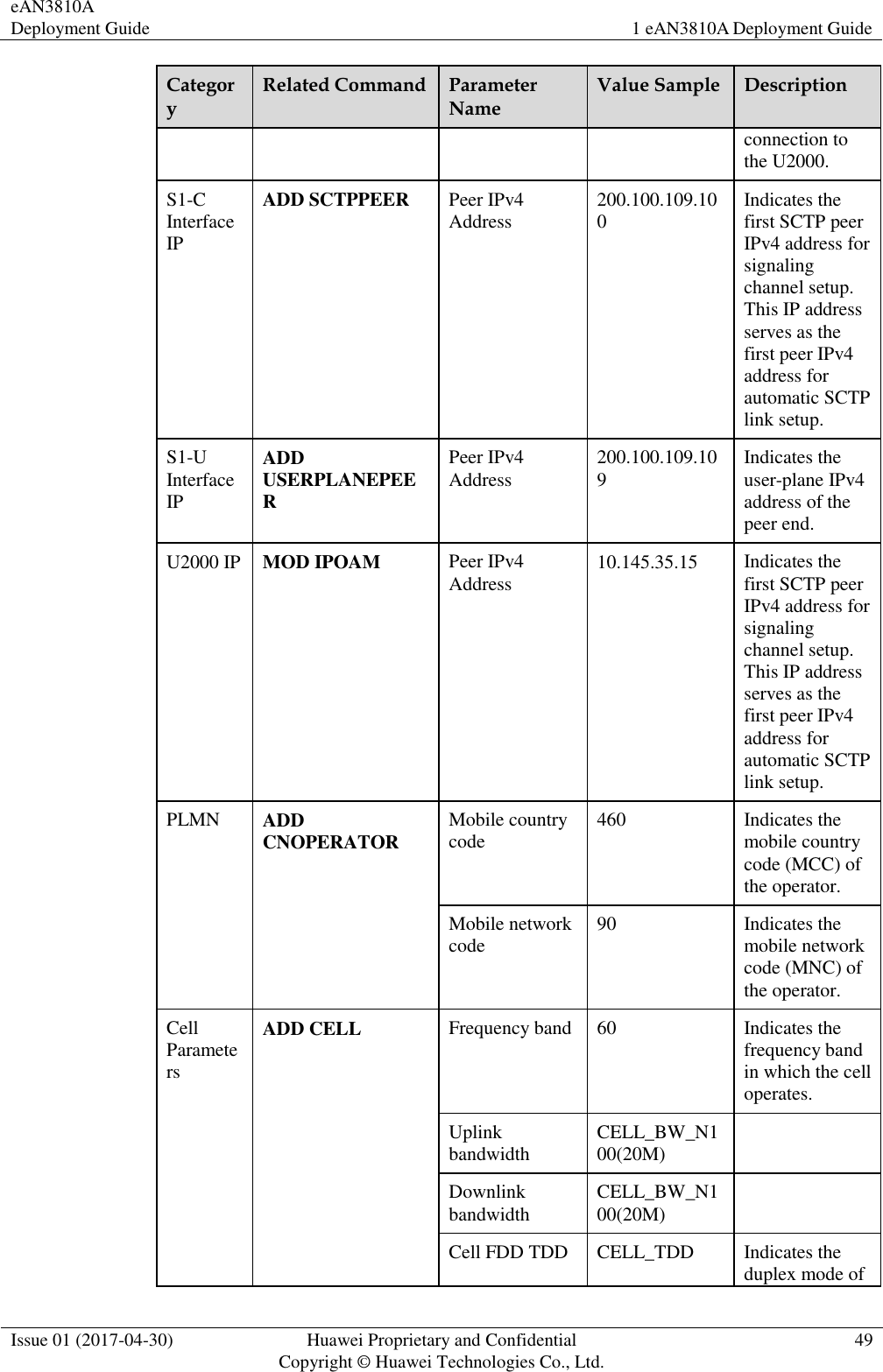
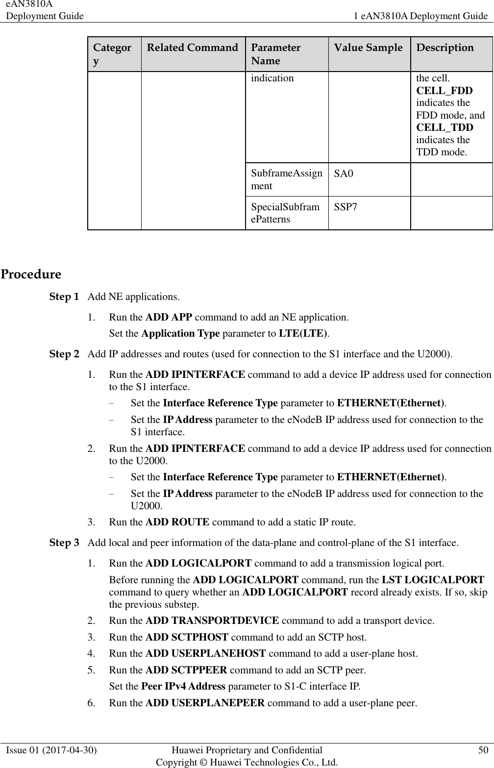
![eAN3810A Deployment Guide 1 eAN3810A Deployment Guide Issue 01 (2017-04-30) Huawei Proprietary and Confidential Copyright © Huawei Technologies Co., Ltd. 14 Figure 1-6 Enterprise Private Network Product (for AirNode Only) a. Click to the right of Auto deployment list to specify the directory where the Auto_Deployment_List_[Date].xml file exported from the CME is stored. b. Click to the right of Precfg file to specify the directory where the preconfiguration file Precfg.ini is stored. c. Click to the right of Software path to specify the directory where the software package is stored. Click Add to add the software package path. d. Deselect the Do not copy .csp file option according to the site deployment scenario. 3. Set the local save paths for the software package and data files based on the type of SD card directory. Then, click OK. And then according to the number of open station number (One USB for One Site or One USB for Multiple Sites) and the output directory, clickStart. When making different types of directories on an SD card, specify items listed in the Information to Set column only and do not set items that are not listed in this column. Option Information to Set Directory for upgrading Software path: mandatory, save path of the files](https://usermanual.wiki/Huawei-Technologies/EAN3810A.Deployment-Guide/User-Guide-3433655-Page-16.png)