Huawei Technologies EAN3810A eLTE-U Airnode User Manual
Huawei Technologies Co.,Ltd eLTE-U Airnode Users Manual
UserManual.wiki
>
Huawei Technologies
>
EAN3810A User Manual
>
Users Manual
Contents
1.
Users Manual
2.
Deployment Guide
3.
Hardware Installation Guide
Users Manual
Navigation menu
Upload a User Manual
Namespaces
Wiki Guide
HTML
PDF
Info
Views
User Manual
Discussion / Help
Navigation
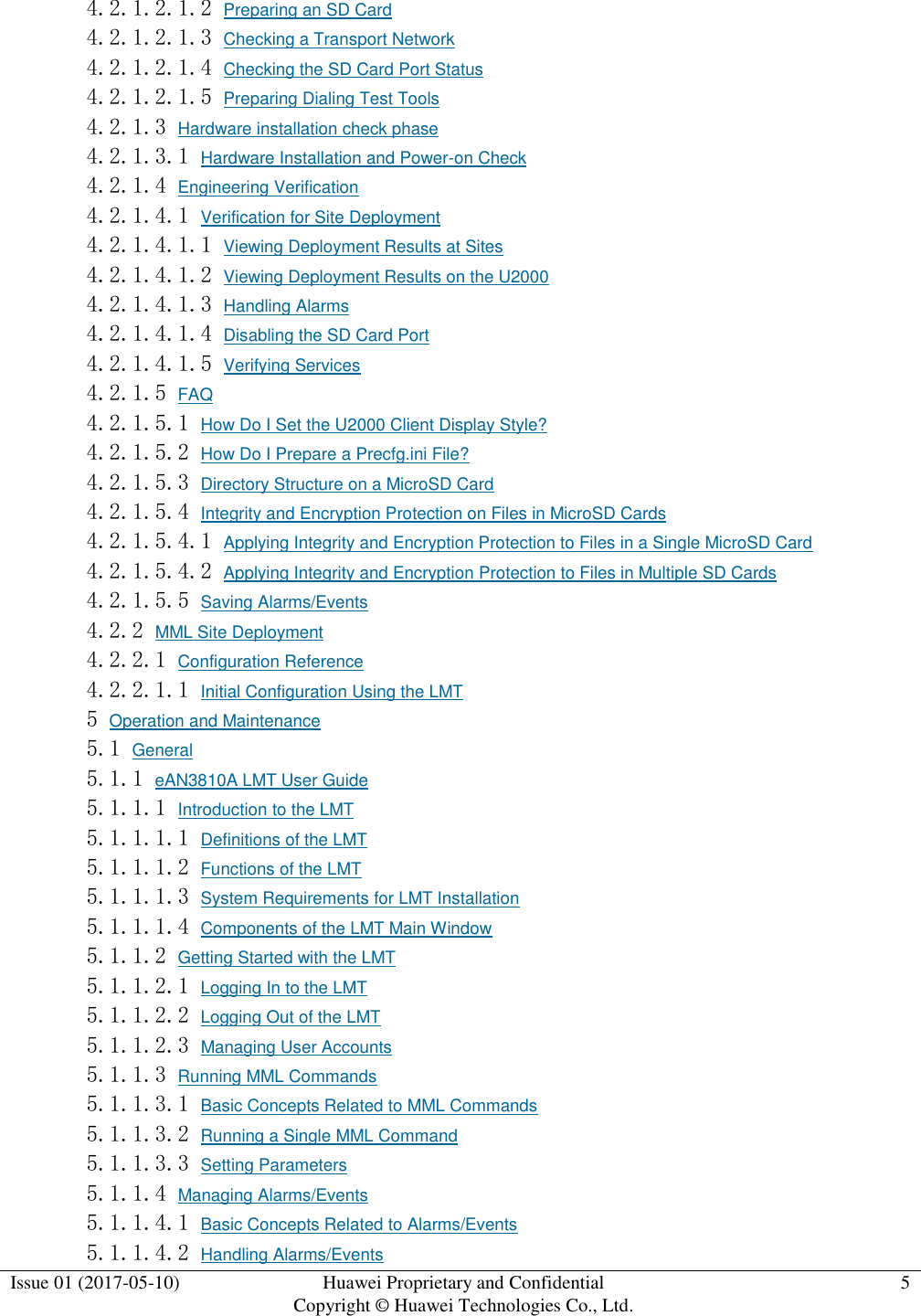
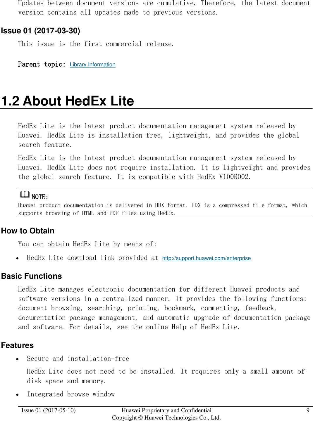
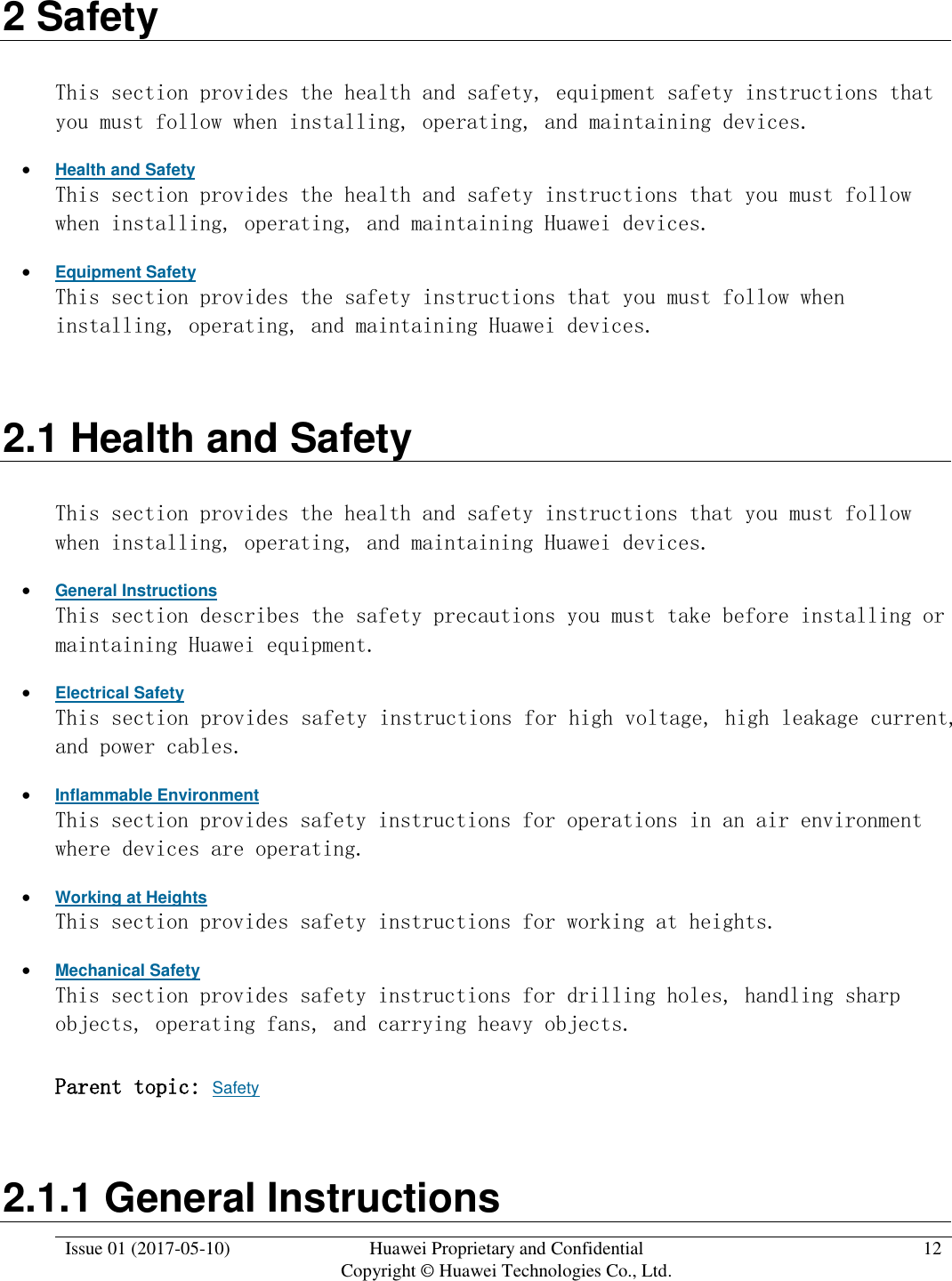
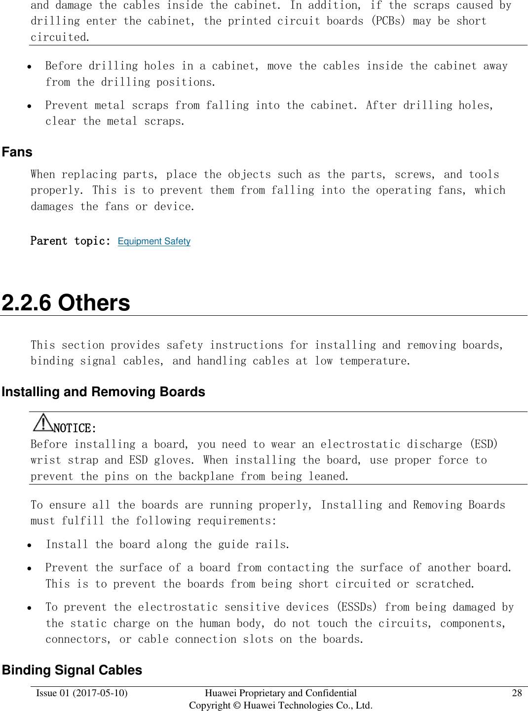
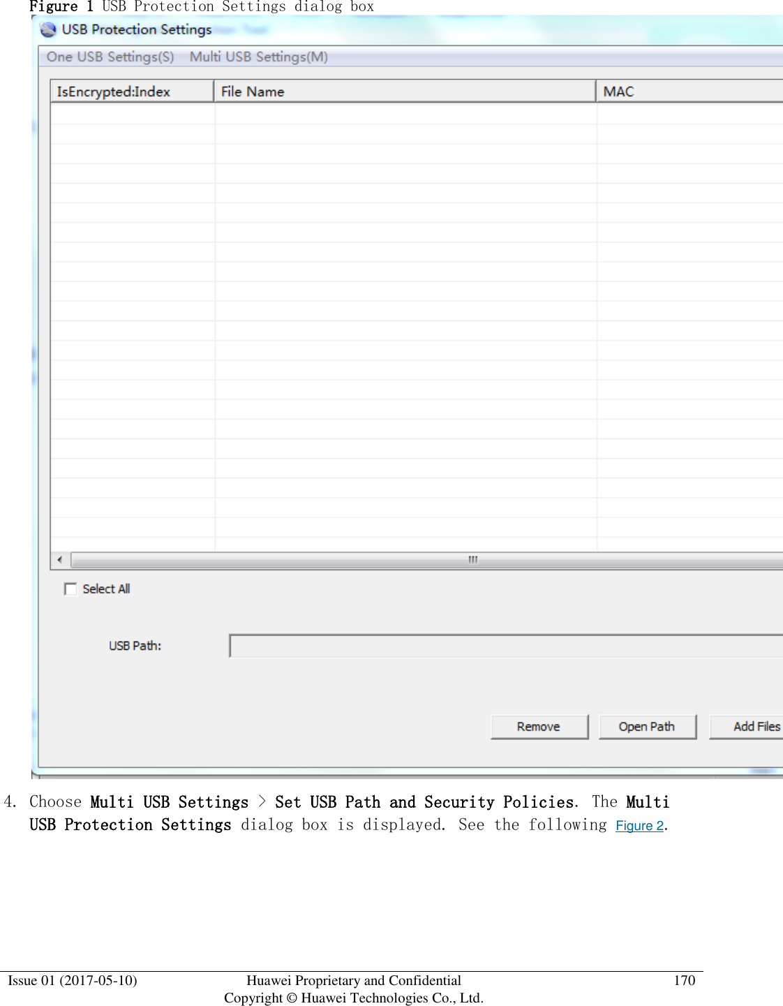
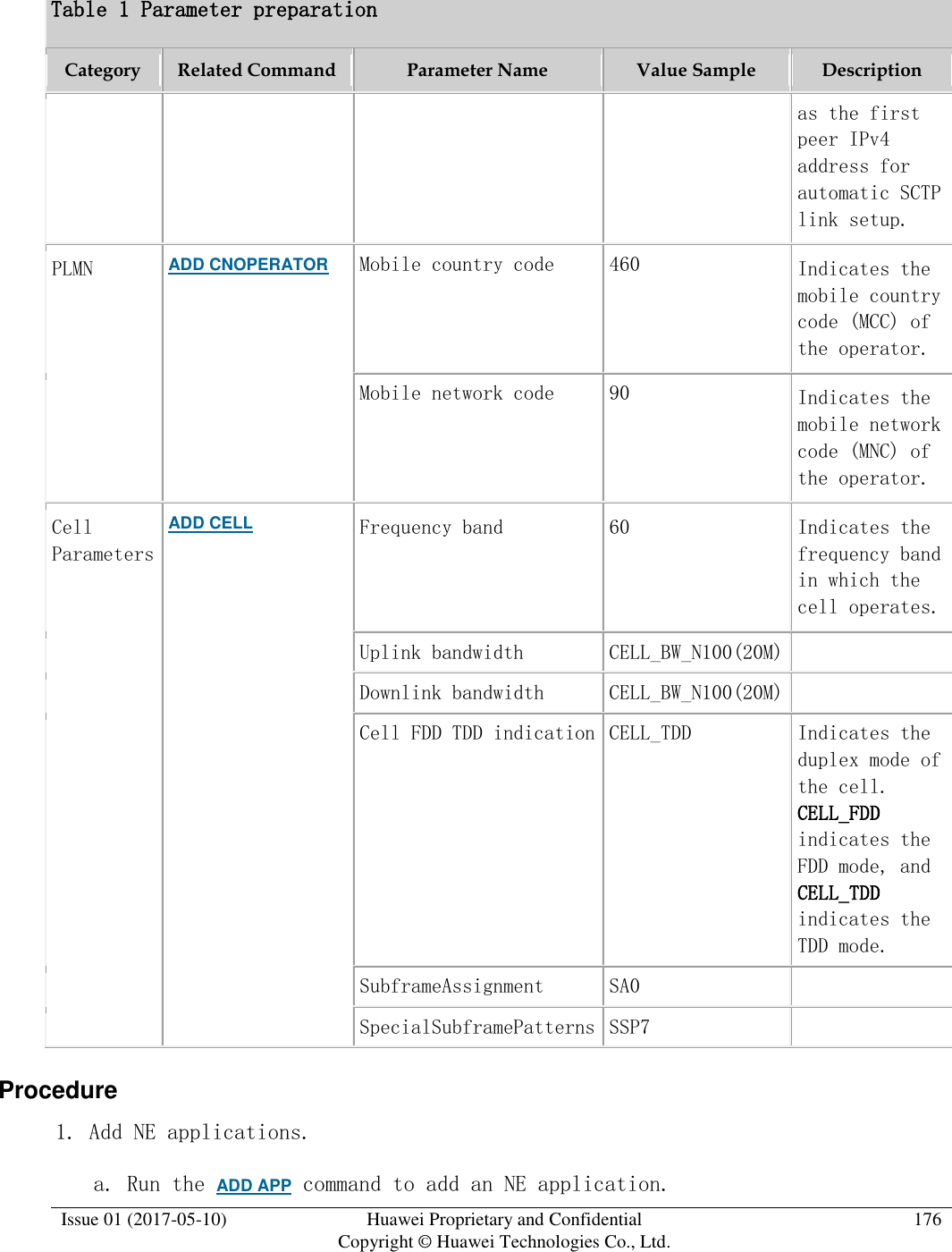
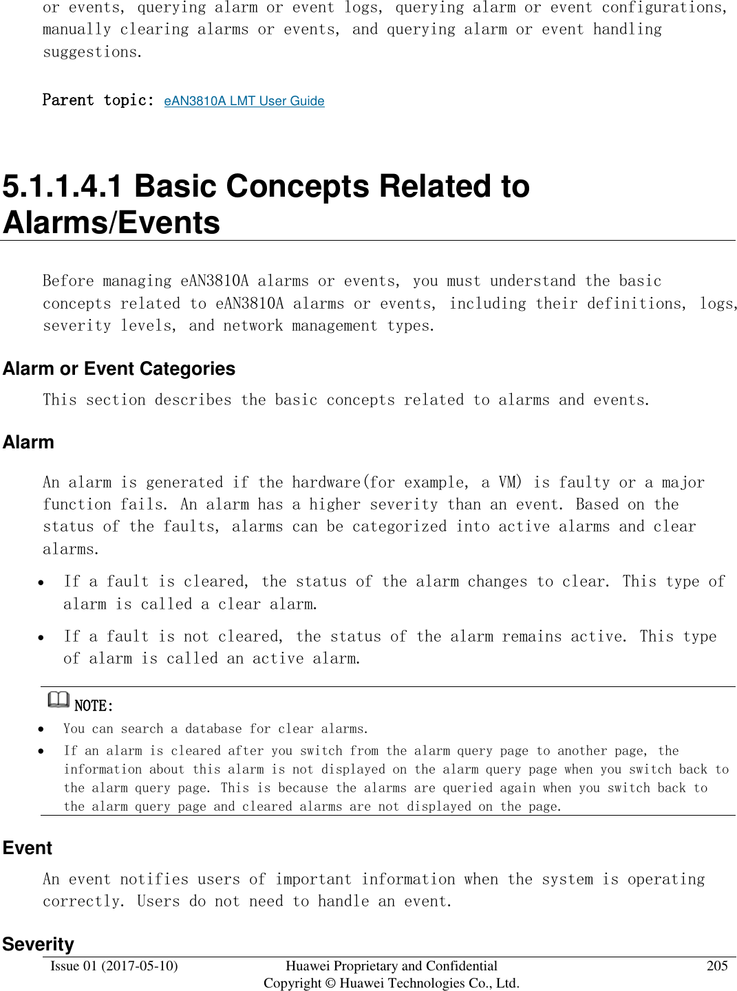
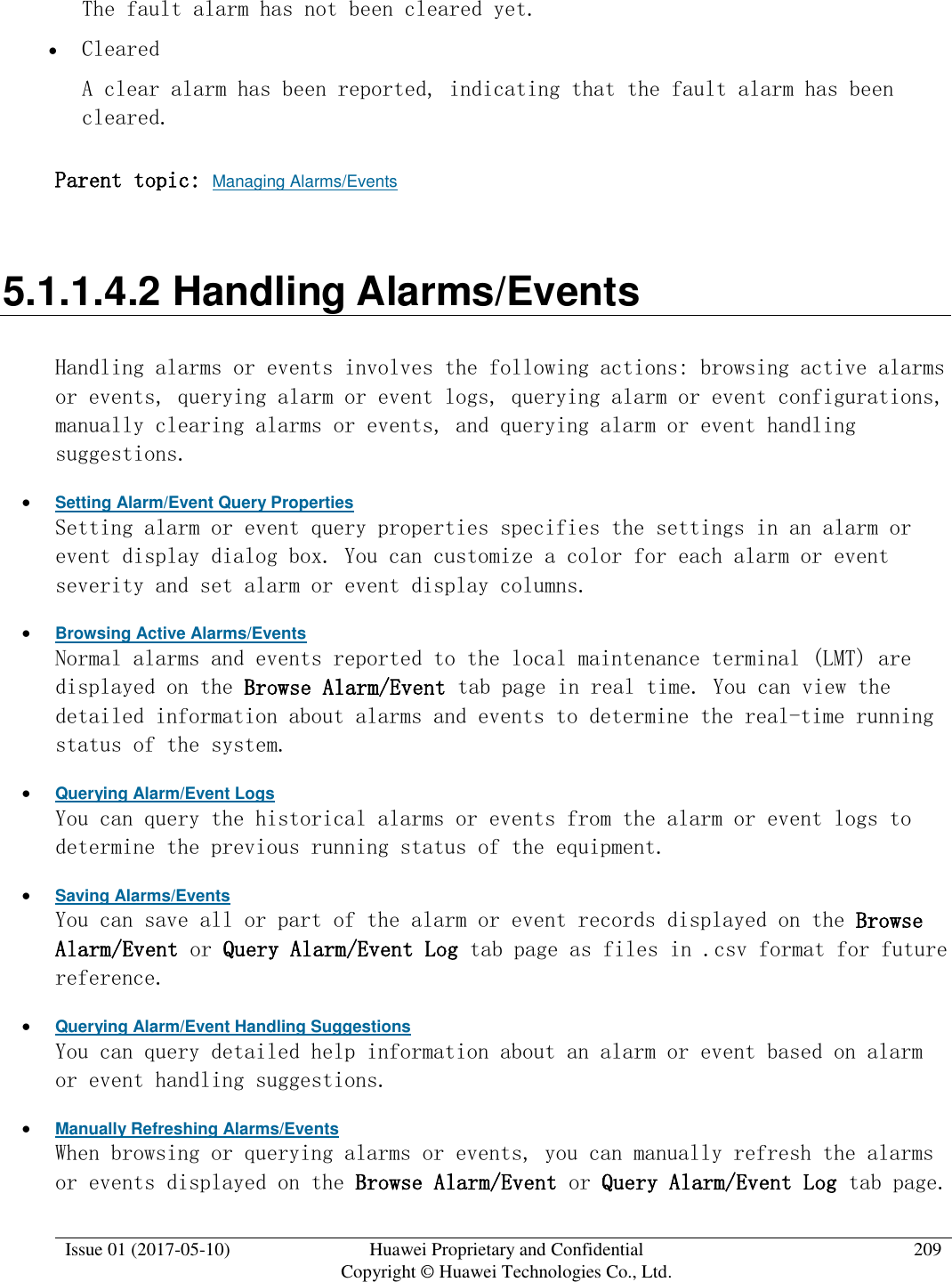
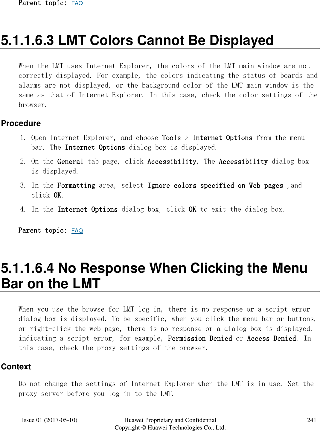
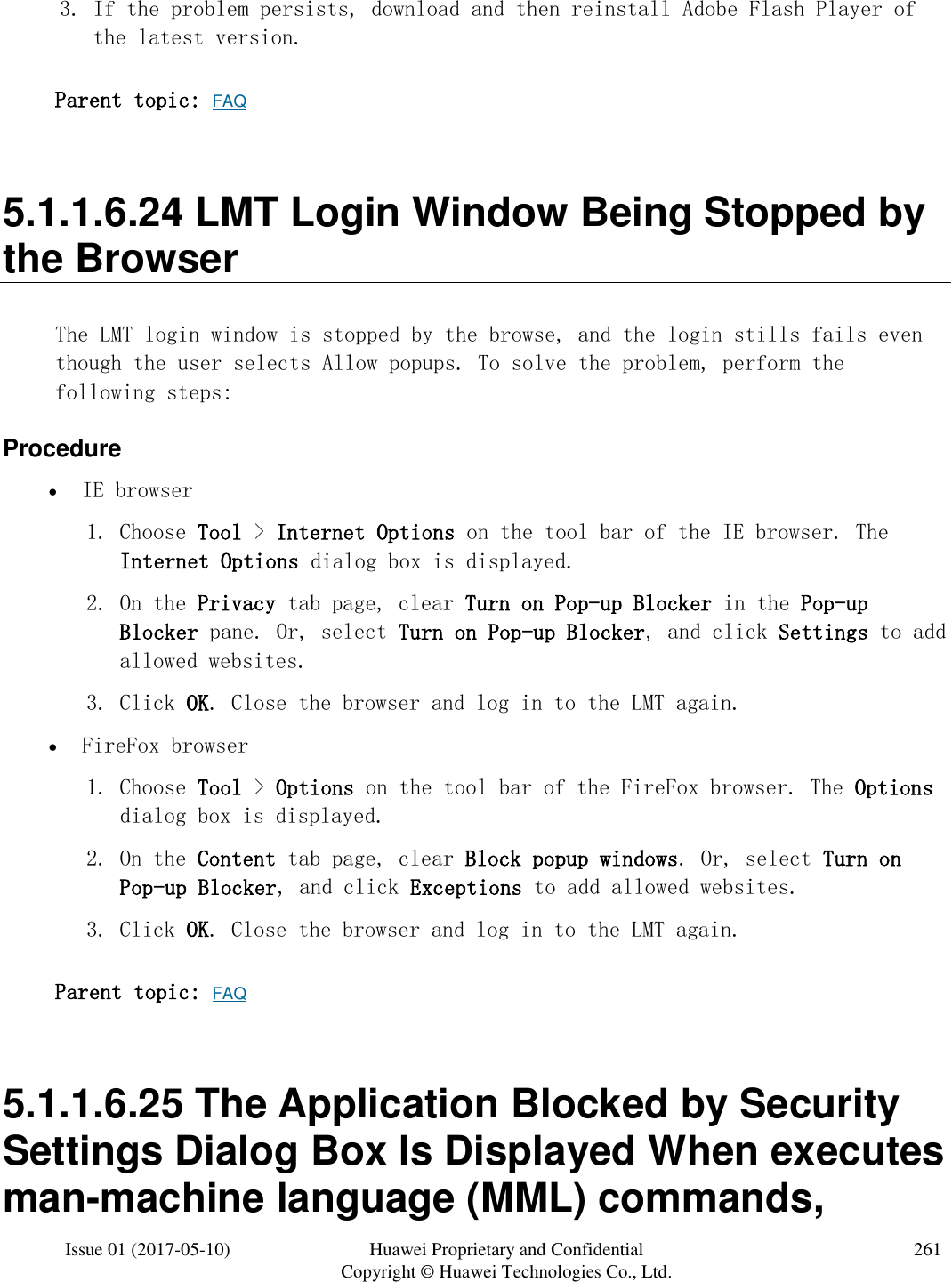
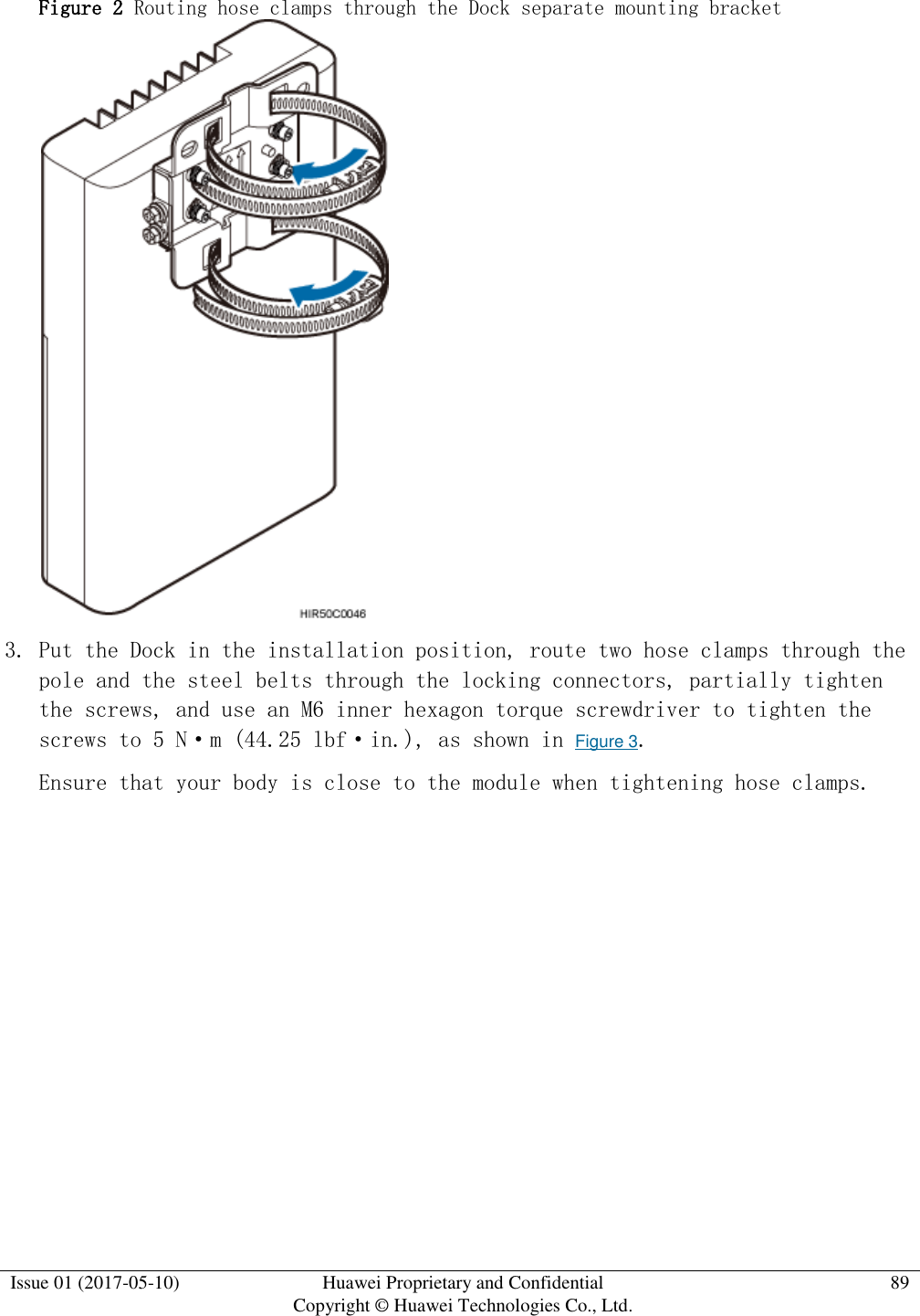
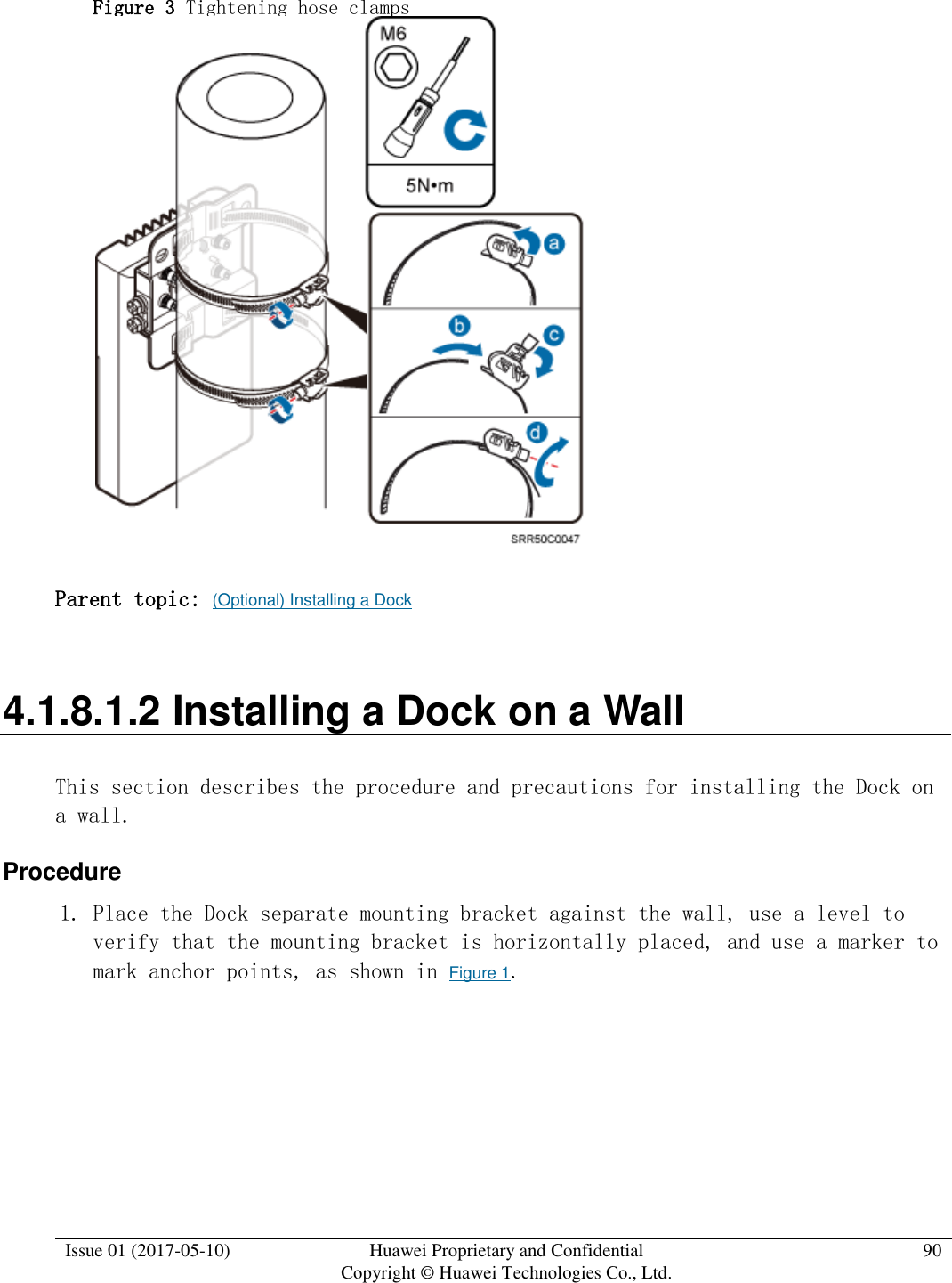
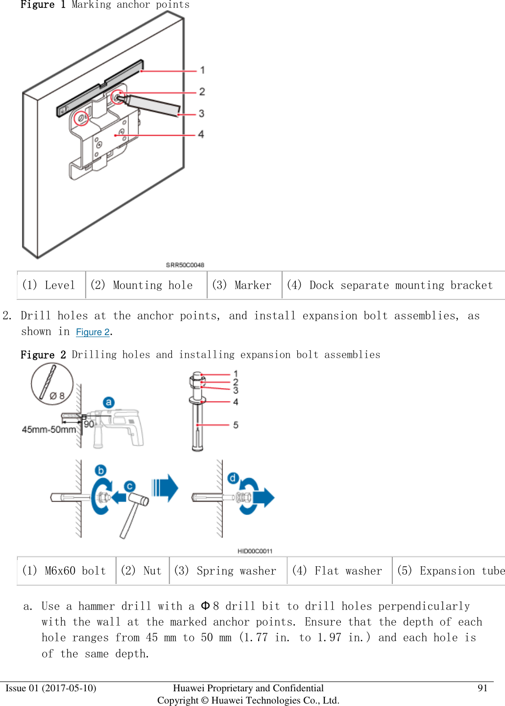
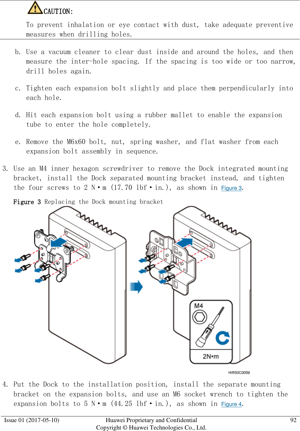
![Issue 01 (2017-05-10) Huawei Proprietary and Confidential Copyright © Huawei Technologies Co., Ltd. 66 [1.26 in.]) Torque wrench Size: 16 mm (0.63 in.) and 22 mm (0.87 in.) Combination wrench Size: 16 mm (0.63 in.) and 22 mm (0.87 in.) 3mm or 5mm (M3 to M6) (M3 to M6) 10 mm [0.39 in.]) Torque socket (M6 or M10) Multimeter Measuring tape Fixed pulley(weight-bearing capacity > 500 kg or 1102.5 lb) Lifting sling Ladder Parent topic: Installation Preparations 4.1.1.3 Requirements for Installation Personnel This section describes requirements for installation engineers. They must be qualified and trained, and familiar with correct operation methods and safety precautions before performing any operations. Before the installation, pay attention to the following items: Technical engineers must take Huawei training and be familiar with proper installation and operation methods.](https://usermanual.wiki/Huawei-Technologies/EAN3810A.Users-Manual/User-Guide-3403560-Page-67.png)
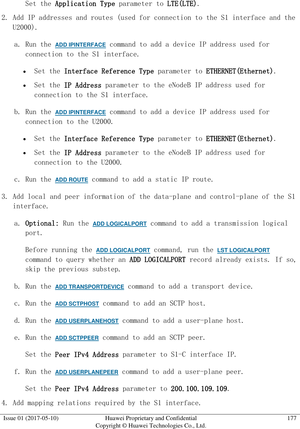
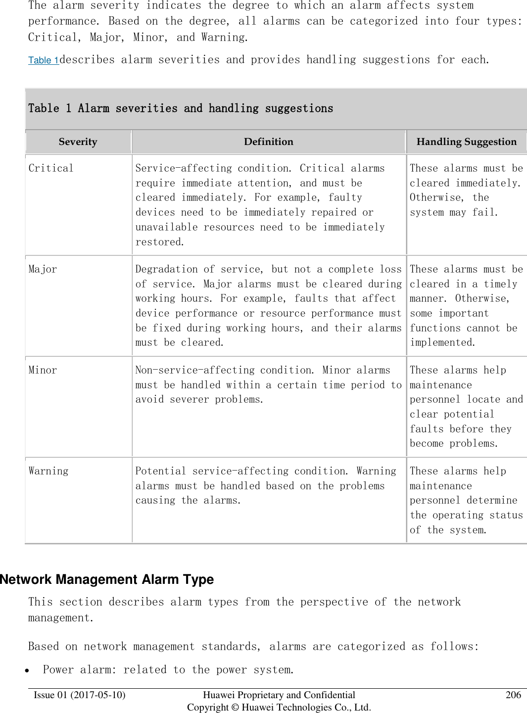
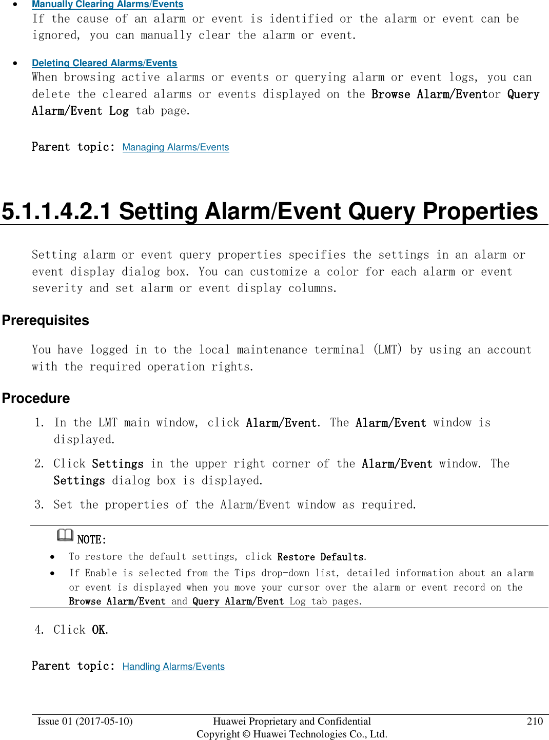
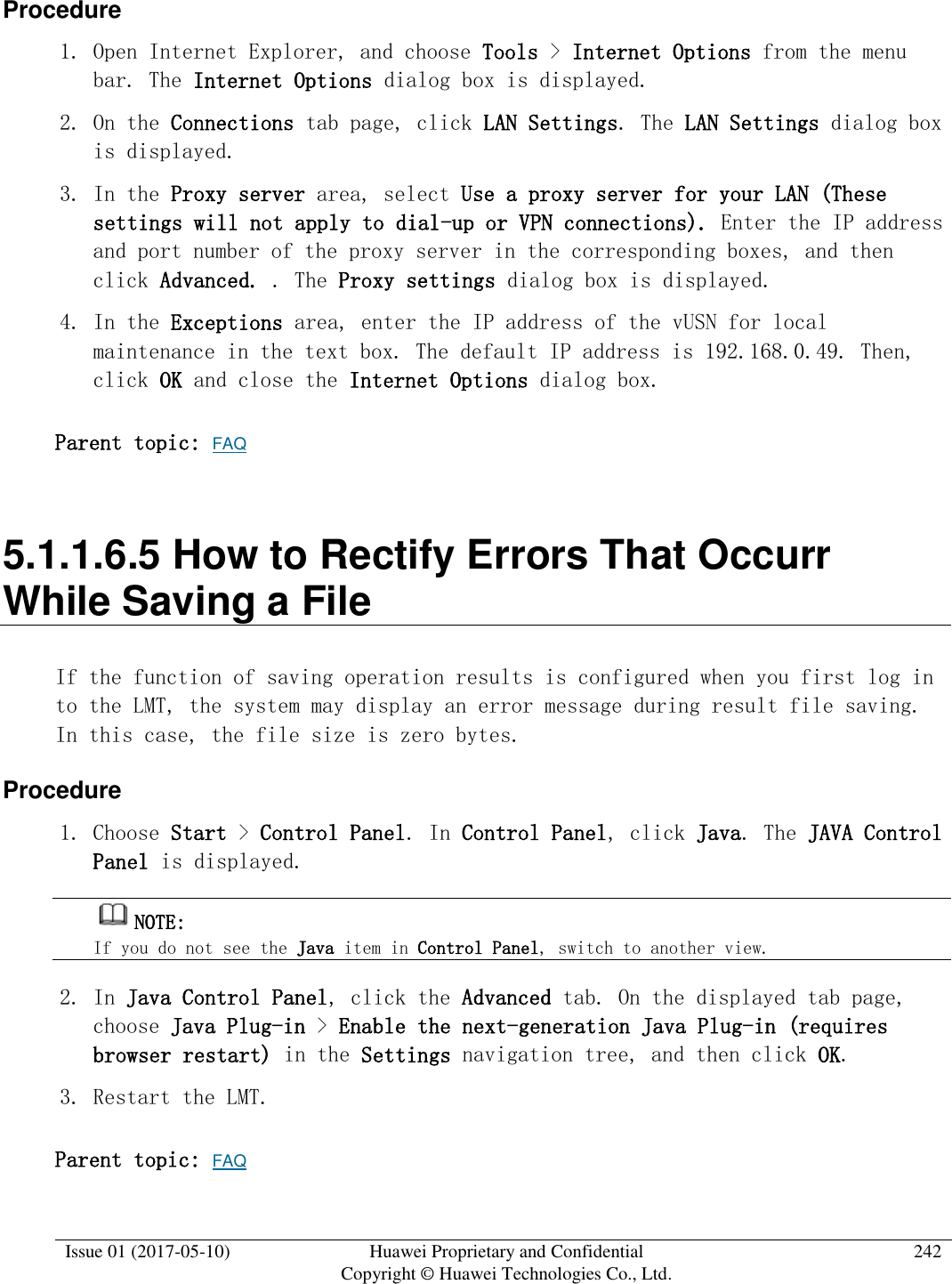
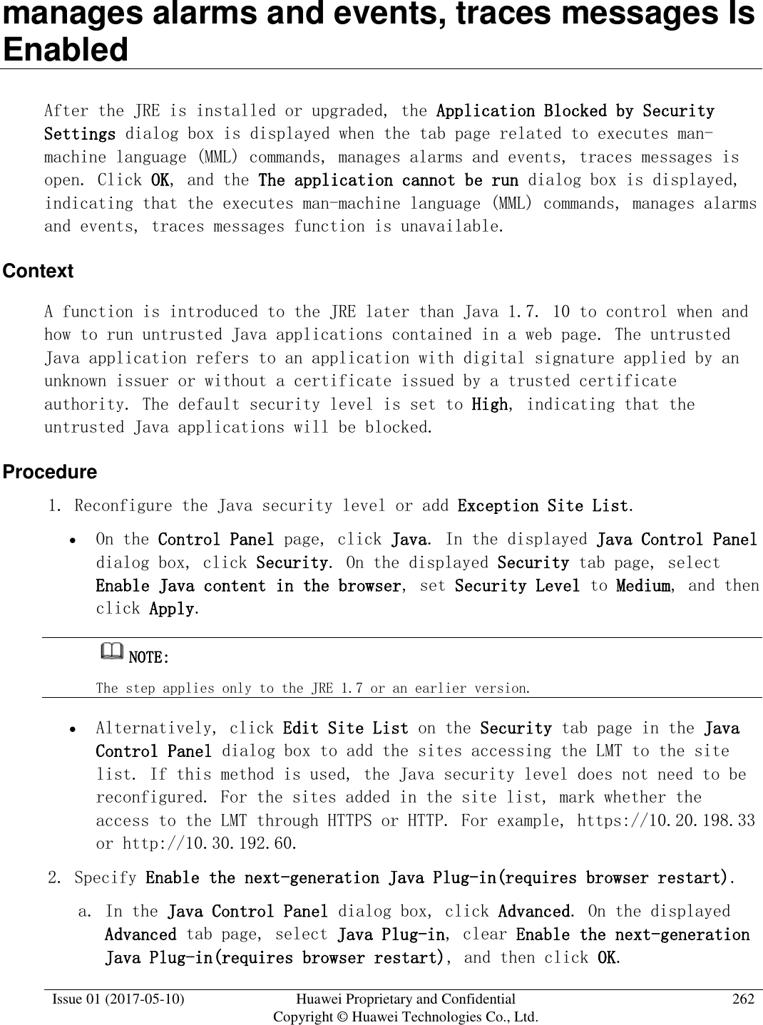
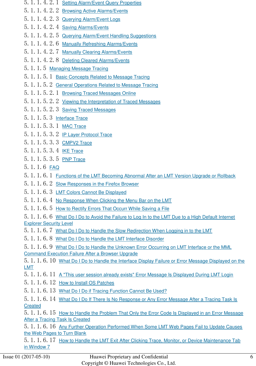
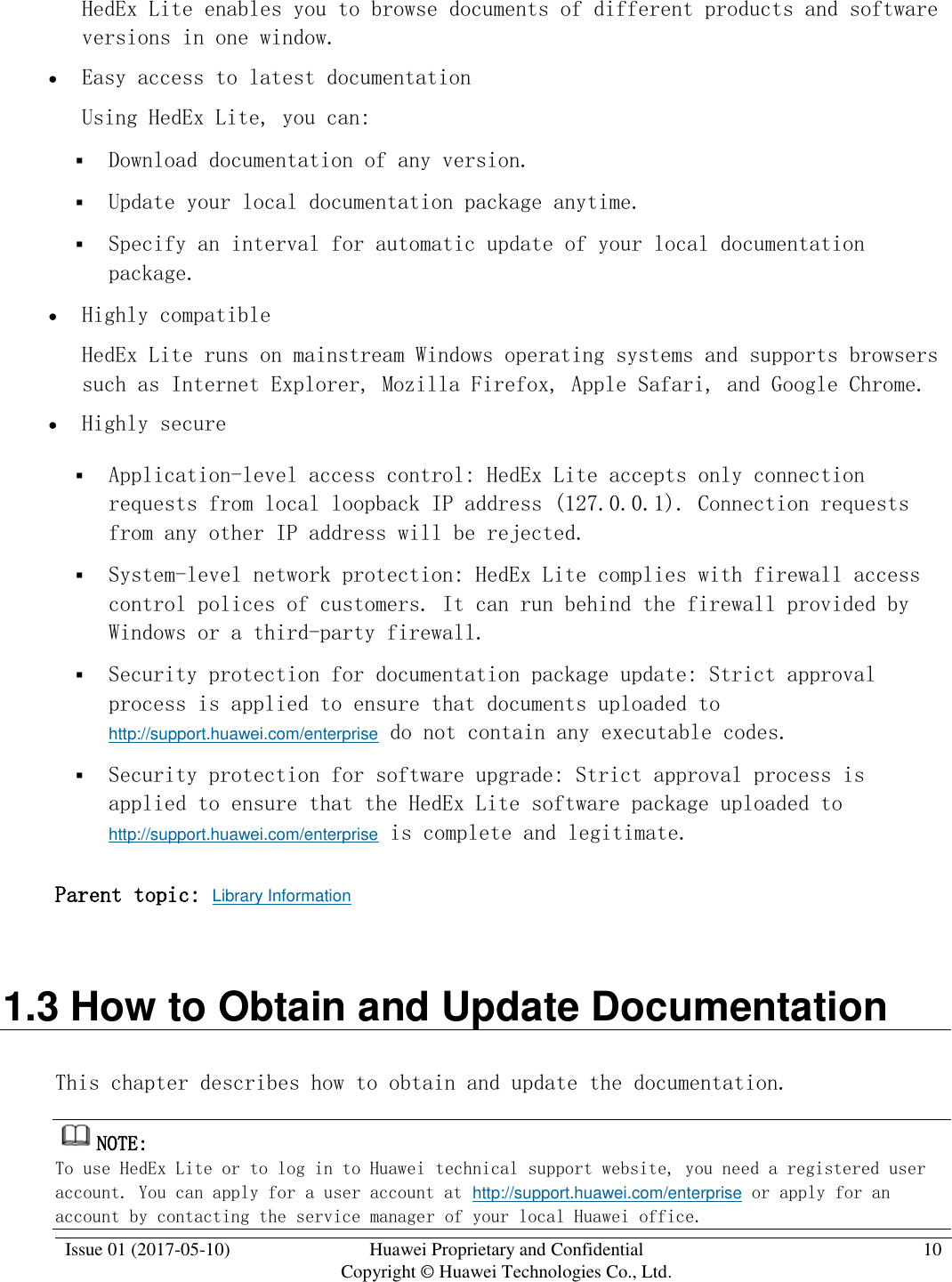
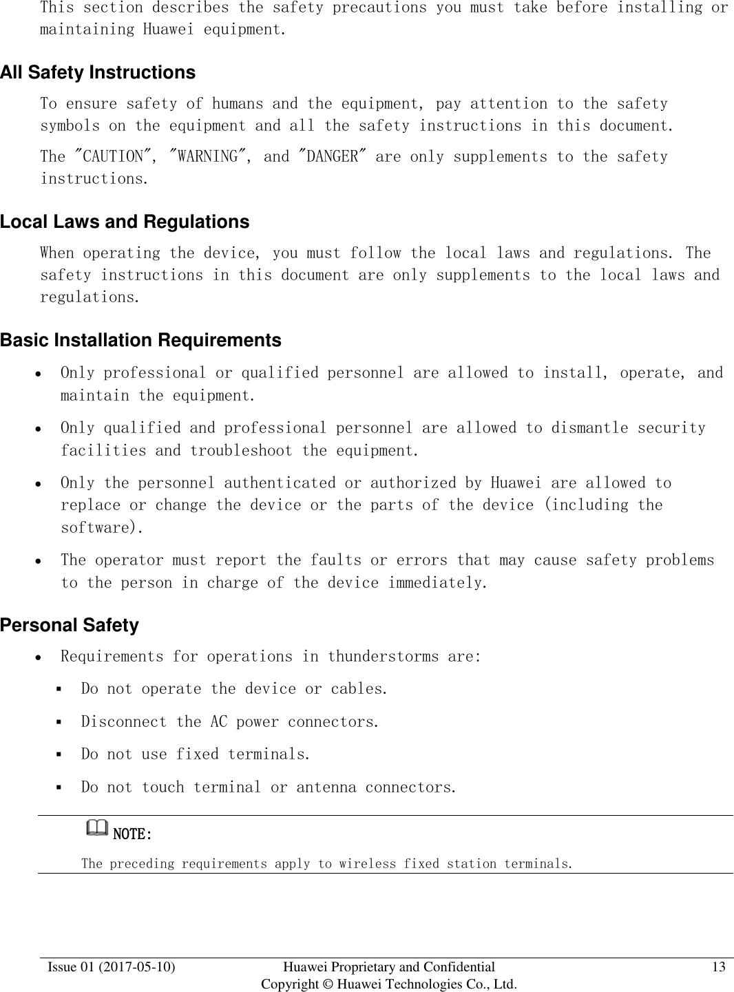
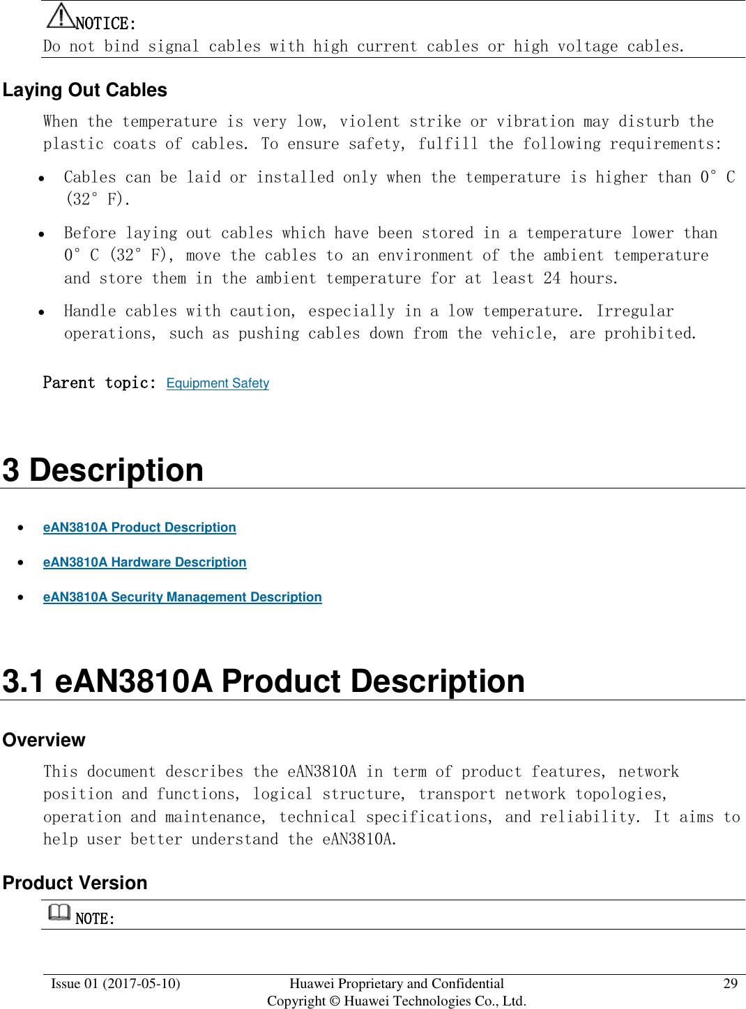
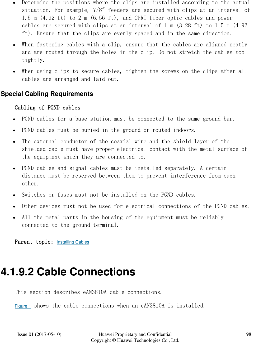
![Issue 01 (2017-05-10) Huawei Proprietary and Confidential Copyright © Huawei Technologies Co., Ltd. 97 Cables must be bound tightly and neatly. The sheaths of cables must not be damaged. Cable ties must face the same direction, and those at the same horizontal line must be in a straight line. The excess of indoor cable ties must be cut off. The excess of 5 mm (0.197 in.) of outdoor cable ties should be reserved, and the cut surfaces must be smooth without sharp edges. After cables are installed, labels or nameplates must be attached to the cables at their ends, curves, and interconnection positions. Security requirements When laying out cables, avoid sharp objects, for example sharp edges on the wall. If necessary, use tubes to protect the cables. When laying out cables, keep cables away from heat sources, or use heat insulation materials to insulate the cables from the heat sources. Reserve a proper distance (0.1 m [3.937 in.] is recommended) between equipment and cables especially at the cable curves to protect the cables and equipment. Indoor cabling requirements Route each cable into the room through the feeder window. Reserve drip loops for all cables outside the feeder window before routing them into the room. Ensure that the radiuses of the drip loops are greater than or equal to the minimum bending radiuses of the cables. When routing a cable into the room, ensure that a person is assisting you in the room. Apply waterproof treatment to the feeder window. Outdoor Cabling Requirements Protect outdoor cables against potential damage. For example, thread the cables through tubes. Cables to be protected include AC power cables, transmission cables, and cables laid out underground. Use cable clips to secure cables outdoors. Arrange cables neatly along the routing direction and use cable clips to secure the cables.](https://usermanual.wiki/Huawei-Technologies/EAN3810A.Users-Manual/User-Guide-3403560-Page-98.png)

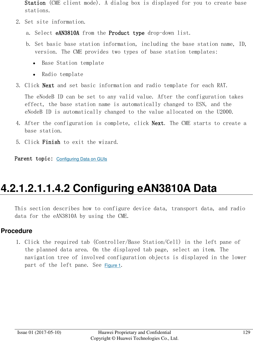
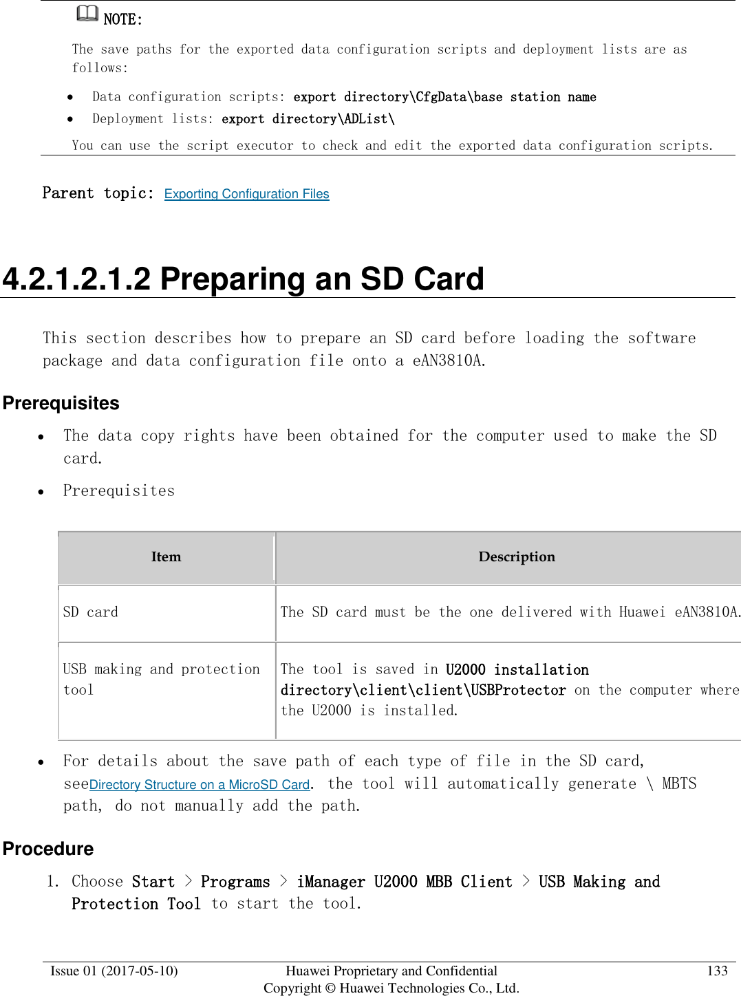
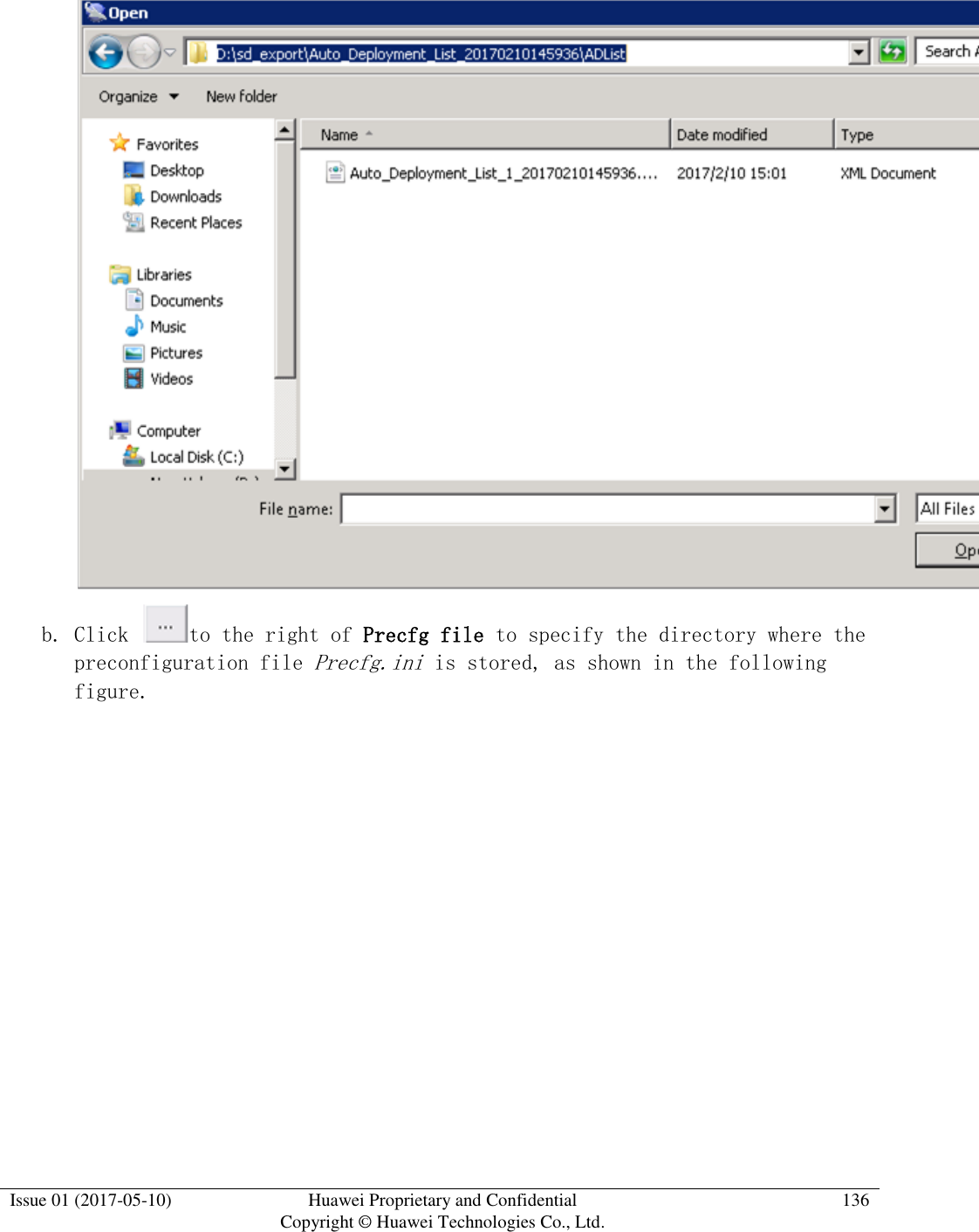
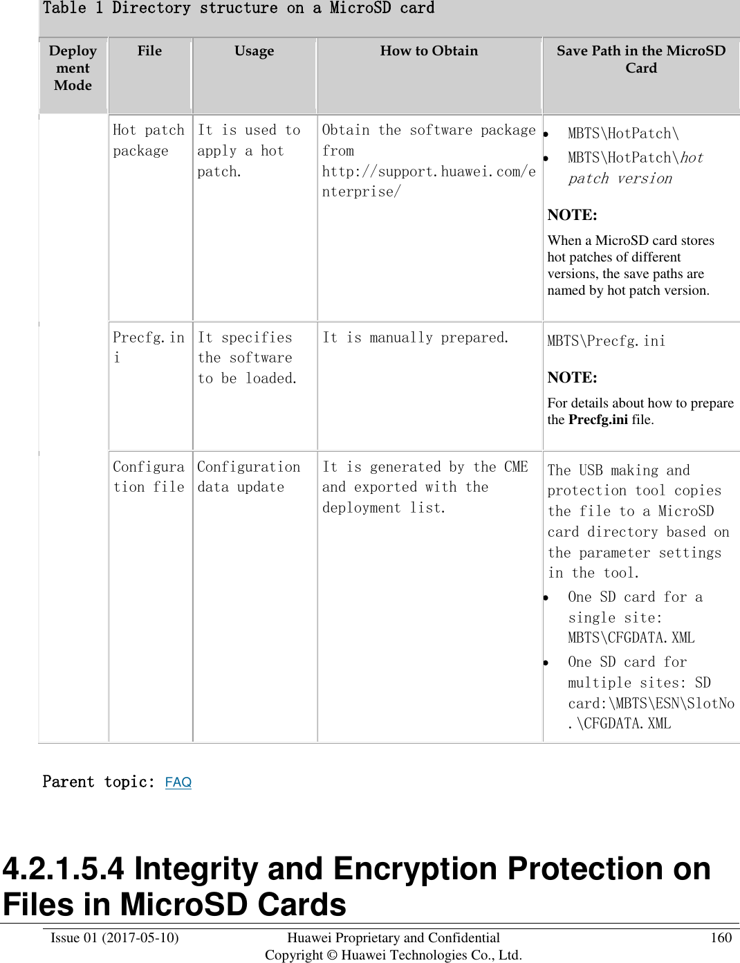
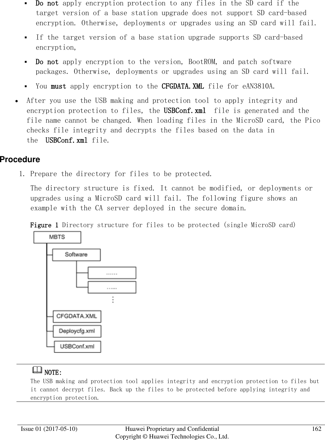
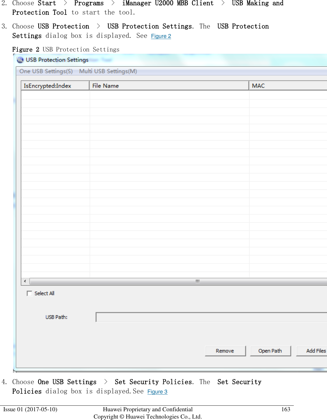
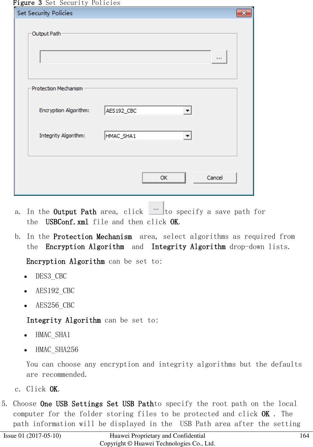
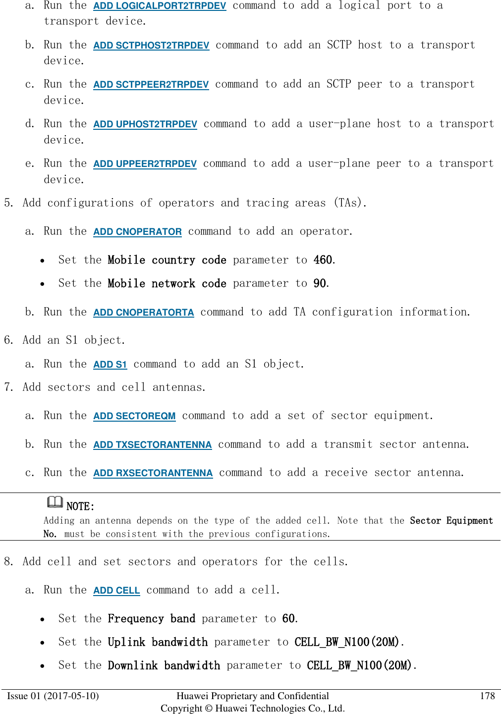
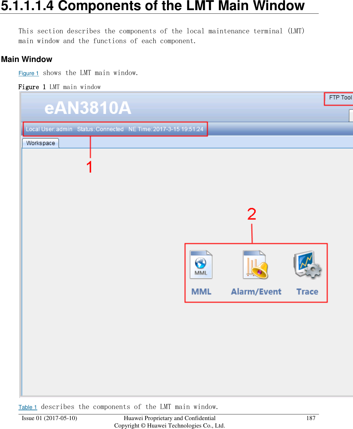
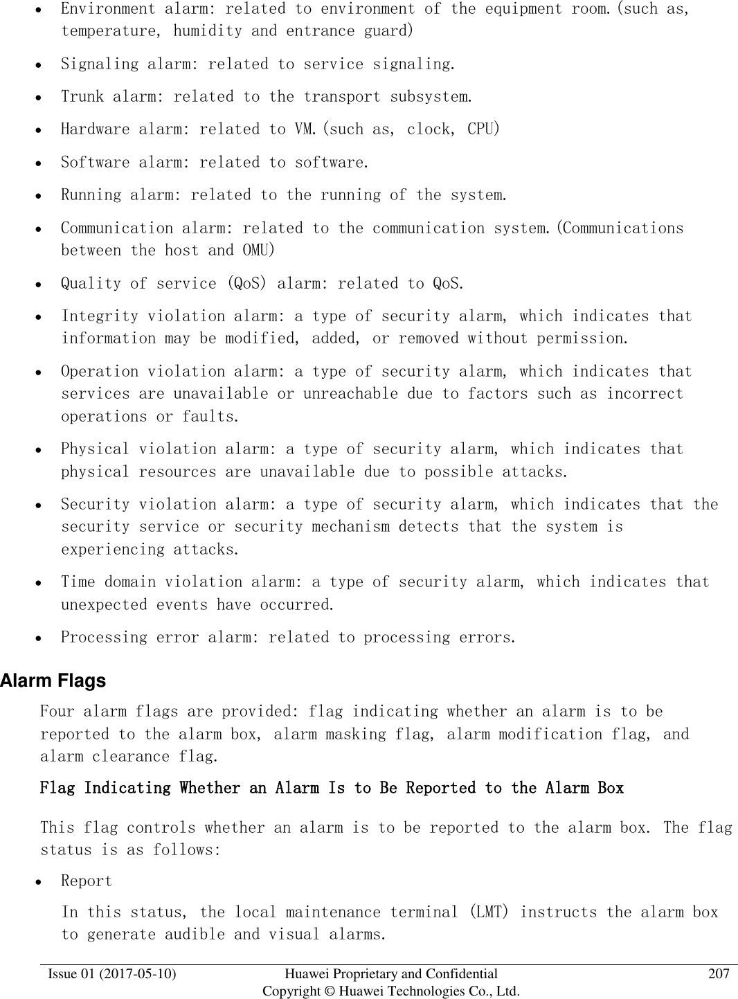
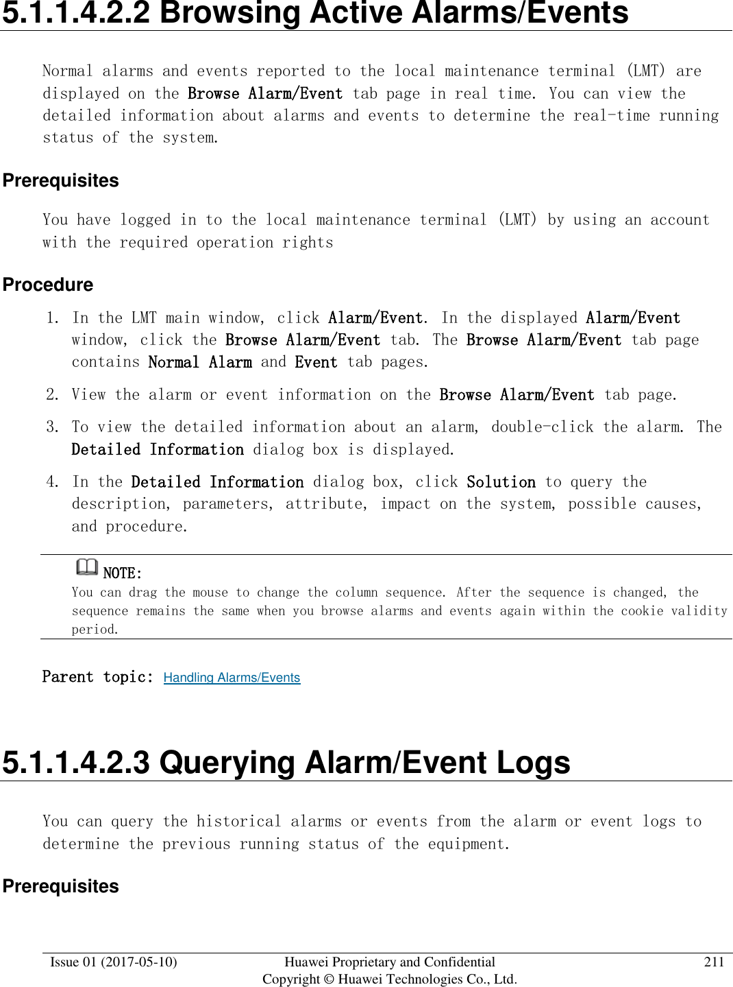
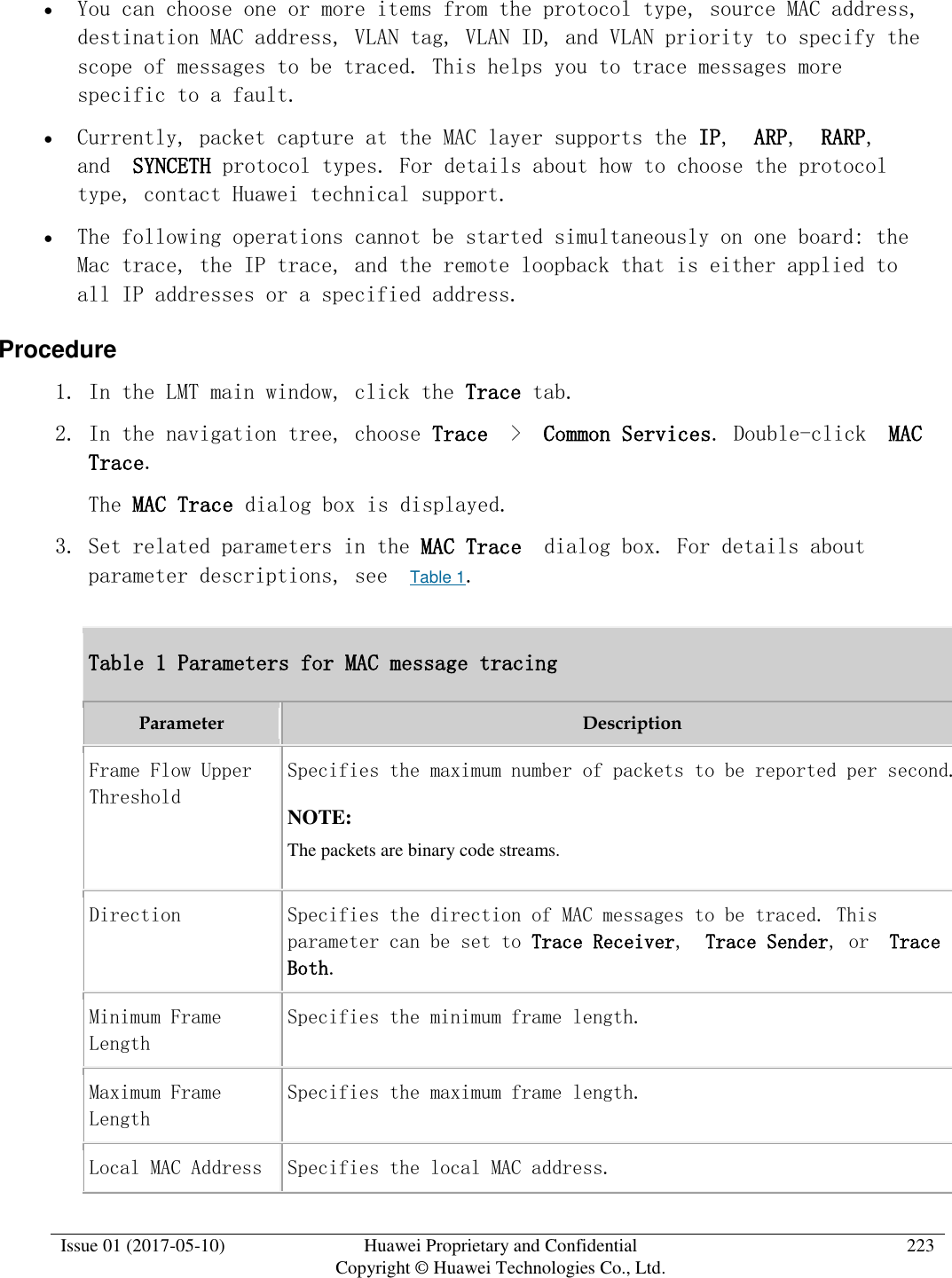
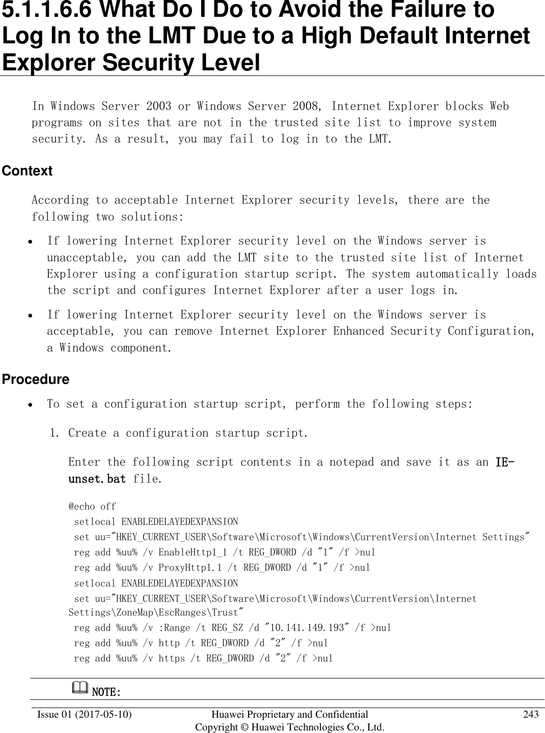
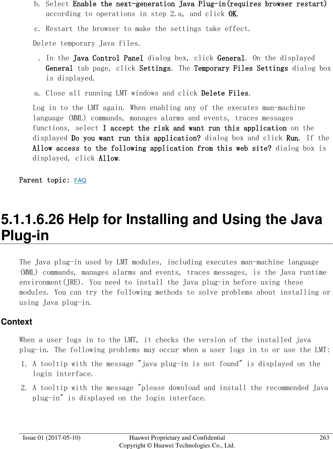
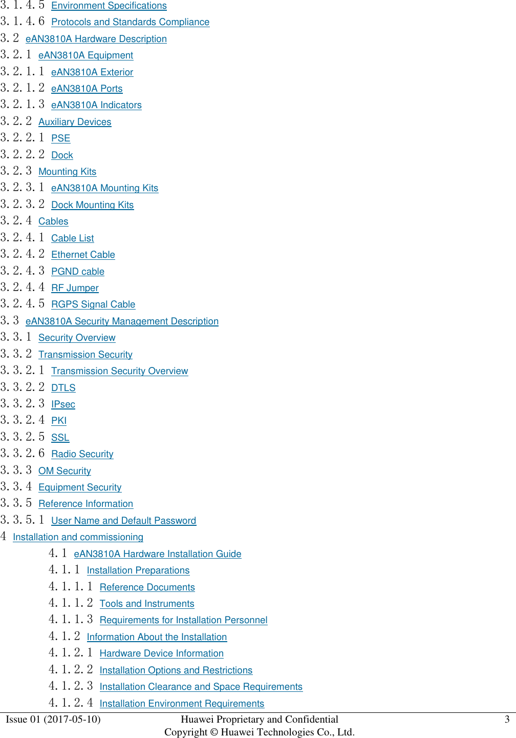
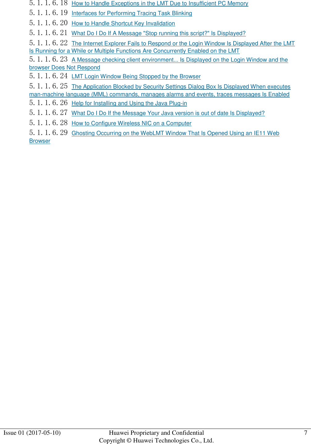
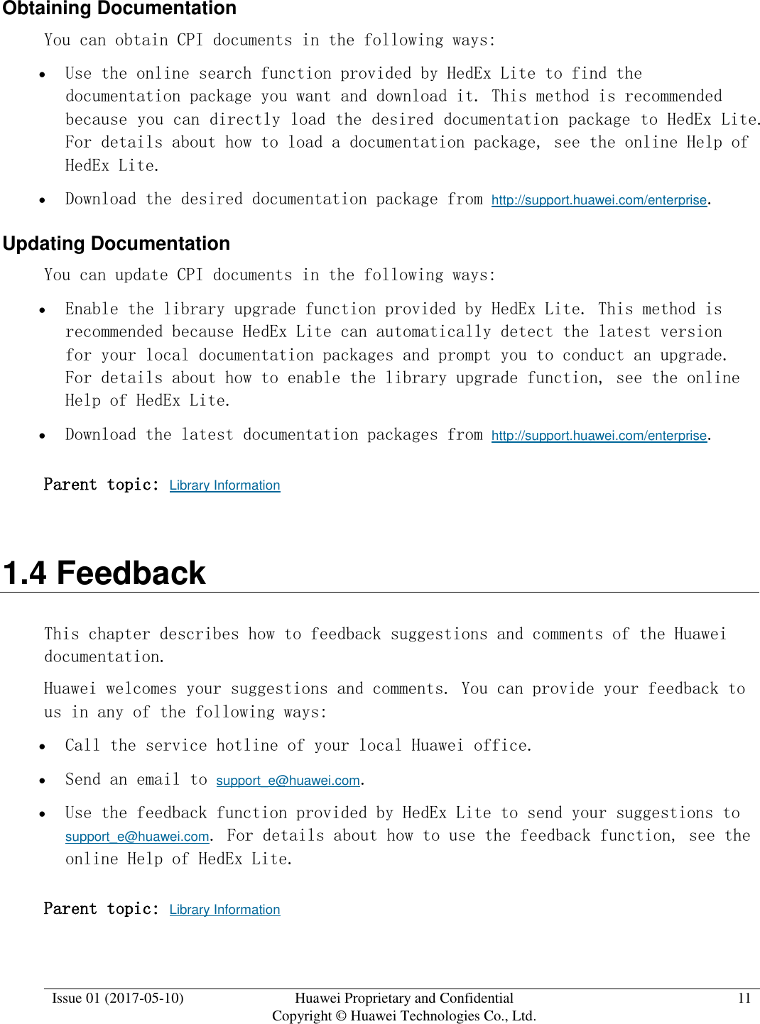
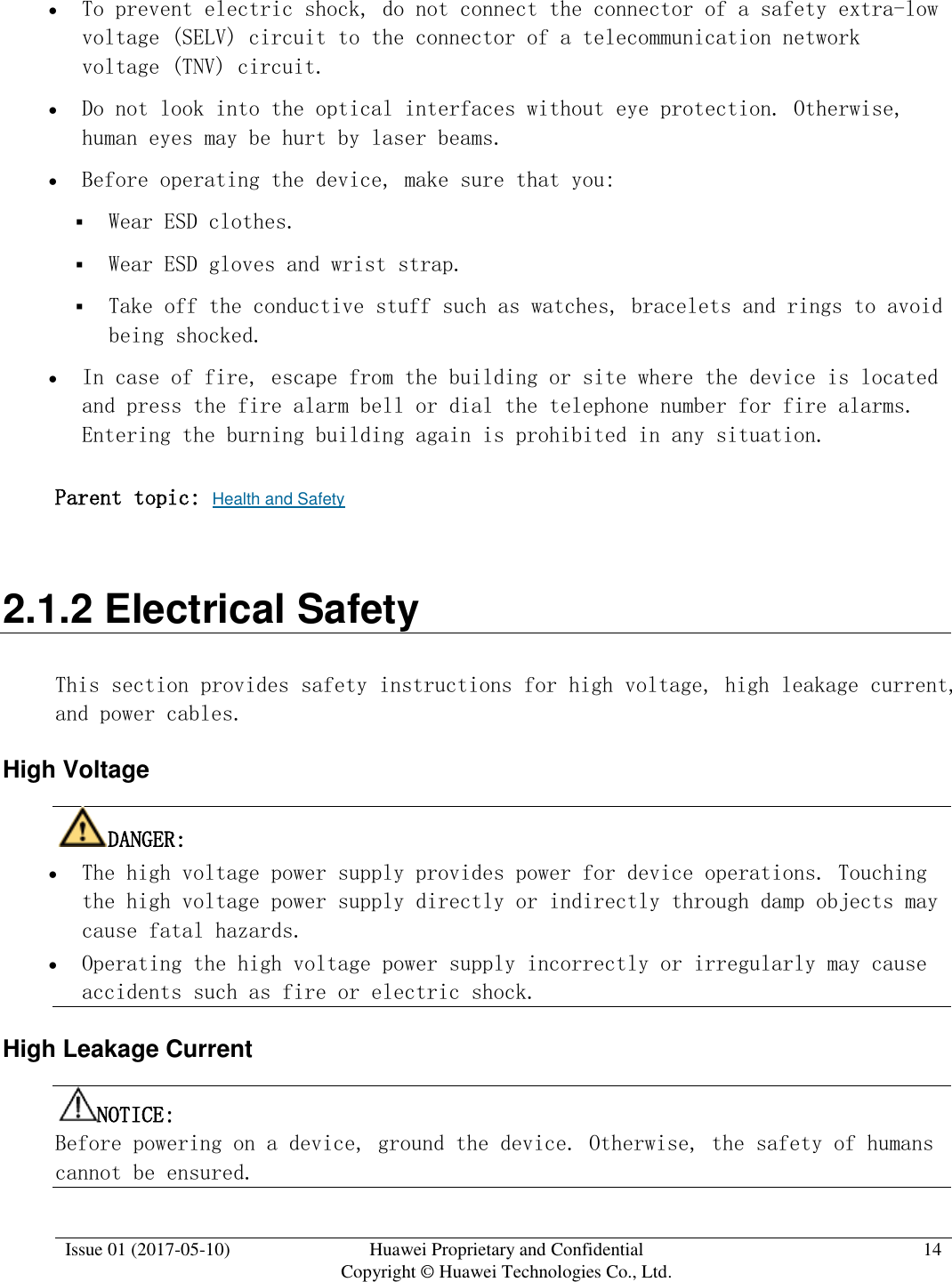
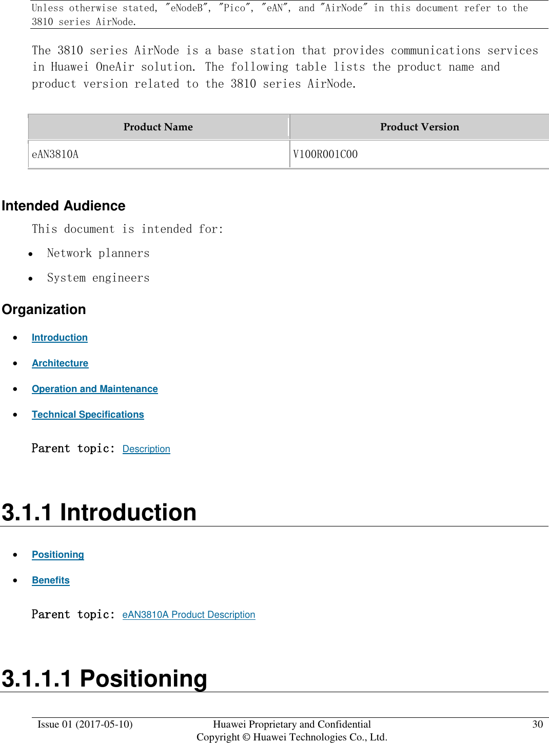
![Issue 01 (2017-05-10) Huawei Proprietary and Confidential Copyright © Huawei Technologies Co., Ltd. 135 Figure 2 Enterprise Private Network Product (for AirNode Only) a. Click to the right of Auto deployment list to specify the directory where the Auto_Deployment_List_[Date].xml file exported from the CME is stored, as shown in the following figure.](https://usermanual.wiki/Huawei-Technologies/EAN3810A.Users-Manual/User-Guide-3403560-Page-136.png)